WO2019009229A1 - 飛行制御装置およびこれを備える無人航空機 - Google Patents
飛行制御装置およびこれを備える無人航空機 Download PDFInfo
- Publication number
- WO2019009229A1 WO2019009229A1 PCT/JP2018/025008 JP2018025008W WO2019009229A1 WO 2019009229 A1 WO2019009229 A1 WO 2019009229A1 JP 2018025008 W JP2018025008 W JP 2018025008W WO 2019009229 A1 WO2019009229 A1 WO 2019009229A1
- Authority
- WO
- WIPO (PCT)
- Prior art keywords
- flight
- control unit
- flight control
- control device
- receiver
- Prior art date
- Legal status (The legal status is an assumption and is not a legal conclusion. Google has not performed a legal analysis and makes no representation as to the accuracy of the status listed.)
- Ceased
Links
Images

Classifications
-
- B—PERFORMING OPERATIONS; TRANSPORTING
- B64—AIRCRAFT; AVIATION; COSMONAUTICS
- B64C—AEROPLANES; HELICOPTERS
- B64C13/00—Control systems or transmitting systems for actuating flying-control surfaces, lift-increasing flaps, air brakes, or spoilers
- B64C13/02—Initiating means
- B64C13/16—Initiating means actuated automatically, e.g. responsive to gust detectors
- B64C13/18—Initiating means actuated automatically, e.g. responsive to gust detectors using automatic pilot
-
- B—PERFORMING OPERATIONS; TRANSPORTING
- B64—AIRCRAFT; AVIATION; COSMONAUTICS
- B64C—AEROPLANES; HELICOPTERS
- B64C13/00—Control systems or transmitting systems for actuating flying-control surfaces, lift-increasing flaps, air brakes, or spoilers
- B64C13/02—Initiating means
- B64C13/16—Initiating means actuated automatically, e.g. responsive to gust detectors
- B64C13/20—Initiating means actuated automatically, e.g. responsive to gust detectors using radiated signals
-
- B—PERFORMING OPERATIONS; TRANSPORTING
- B64—AIRCRAFT; AVIATION; COSMONAUTICS
- B64U—UNMANNED AERIAL VEHICLES [UAV]; EQUIPMENT THEREFOR
- B64U10/00—Type of UAV
- B64U10/10—Rotorcrafts
- B64U10/13—Flying platforms
- B64U10/16—Flying platforms with five or more distinct rotor axes, e.g. octocopters
-
- G—PHYSICS
- G08—SIGNALLING
- G08G—TRAFFIC CONTROL SYSTEMS
- G08G5/00—Traffic control systems for aircraft
-
- B—PERFORMING OPERATIONS; TRANSPORTING
- B64—AIRCRAFT; AVIATION; COSMONAUTICS
- B64U—UNMANNED AERIAL VEHICLES [UAV]; EQUIPMENT THEREFOR
- B64U2101/00—UAVs specially adapted for particular uses or applications
- B64U2101/30—UAVs specially adapted for particular uses or applications for imaging, photography or videography
Definitions
- the present invention relates to unmanned aerial vehicle technology.
- Patent Document 1 discloses a flight control device provided with a sub-control device capable of interrupting the processing of a main control device that controls the flight operation of an unmanned aerial vehicle.
- a small unmanned aerial vehicle represented by a multicopter is provided with a control device called a flight controller that controls the flight operation of the airframe.
- a flight controller that controls the flight operation of the airframe.
- Some flight controller products distributed in the market have an autopilot function.
- the autopilot function is a function to make the aircraft fly autonomously along a flight plan created by the pilot.
- a typical autopilot flight plan can specify the take-off and landing points of the airframe, the latitude and longitude of the flight route, the altitude in flight, the speed, the azimuth angle of the nose, and the like.
- some flight controllers specialized for aerial photography can specify start / end of shooting by a camera, PTZ operation, and the like.
- these autopilot functions are merely executing a combination of general-purpose operations.
- For autopilot flight planning it is not possible to use sensors that are not peripheral devices of the flight controller (e.g. separately mounted side-directed laser ranging sensors etc). Also, it is not possible to dynamically change the flight operation to be performed according to the situation at the time of flight (except for the fail safe function). That is, with the conventional autopilot function, it is difficult to make flight operation flexible and accurate for unusual special applications.
- the function can only be expanded within the range permitted by the API provided by the manufacturer.
- the flight controller used may differ depending on the application of the unmanned aerial vehicle and the airframe, and it is inefficient to implement the same extension function in various manners in accordance with the flight controller.
- the problem to be solved by the present invention is to provide a flight control device capable of efficiently realizing a special autonomous flight operation and an unmanned aerial vehicle provided with the same.
- the flight control device of the present invention is a signal output from a main control unit mounted on an unmanned aerial vehicle and controlling the flight operation of the unmanned aerial vehicle, and a receiver receiving a steering signal from an operator. And generating a pseudo signal which is a signal of the same type, and a sub control unit capable of inputting the pseudo signal to the main control unit.
- the sub control unit By providing the sub control unit with the flight control device, for example, using a commercially available flight controller product as the main control unit, and realizing only the flight operation that can not be realized by the auto pilot function possessed by the flight controller using pseudo signals Is possible.
- the output signal of the receiver is mostly standardized. Therefore, the same pseudo signal can be input as an indication of the same meaning content to various flight controller products.
- flight controller products to which the receiver can not be connected that is, flight controller products to which pseudo signals can not be input, are considered to be only a very small number of exceptional products, if any.
- the sub control unit has a storage unit, and a pseudo signal routine that is a generation pattern of the pseudo signal over time is registered in the storage unit.
- the pilot can easily cause the unmanned aircraft to perform a desired autonomous flight operation by calling the pseudo signal routine at an arbitrary timing. it can.
- the flight control device of the present invention further includes a flight control sensor group which is a plurality of sensors for detecting the attitude and / or the flight position of the airframe, and the sub control unit uses the detection value of the flight control sensor group. It is preferable that the generation content of the pseudo signal can be dynamically changed on the basis of this.
- the sub control unit can dynamically change the flight operation instructed to the unmanned aircraft based on the detection values of the flight control sensor group, thereby broadening the range of autonomous flight operation that can be realized by the sub control unit, and The accuracy of the operation can be enhanced.
- the main control unit and the sub control unit have separate flight control sensor groups.
- the sub control unit Since the sub control unit has a flight control sensor group separately from the main control unit, the type of flight control sensor group provided on the airframe and the mounting method thereof (internal or external to the main control unit), main control It is possible to avoid that the function of the sub control unit is restricted by the specification of the unit (transferability of sensor detection value, etc.), and it is possible to exhibit the original function of the sub control unit with various machines.
- the flight control device of the present invention may further include a receiver for receiving a steering signal from a pilot, and the receiver may be connected to the sub control unit.
- the receiver Since the receiver is connected to the sub-control unit, it is possible to easily switch between the manual operation by the operator and the control of the airframe by the pseudo signal.
- the signal of the receiver input to the sub control unit may be transferred to the main control unit as it is.
- the flight control device of the present invention may further include a receiver for receiving a steering signal from a pilot, and the sub control unit may be configured to have macro recording means for recording a signal output from the receiver. .
- the pseudo signal routine when creating a new pseudo signal routine, can be made efficient by actually operating the aircraft, recording the output signal of the receiver at that time, and creating a pseudo signal routine based on this. Can be created.
- the unmanned aerial vehicle of this invention is characterized by being equipped with the flight control apparatus of this invention.
- the pseudo signal routine when creating a new pseudo signal routine, can be made efficient by actually operating the aircraft, recording the output signal of the receiver at that time, and creating a pseudo signal routine based on this. Can be created.
- the embodiments described below are all examples in which the flight control device of the present invention is mounted on a multicopter which is a small unmanned rotary wing aircraft.
- the aircraft to which the flight control device of the present invention can be applied is not limited to the multicopter.
- the flight control device of the present invention is applicable to helicopters, fixed wing aircraft, and even VTOL aircraft (Vertical Take-Off and Landing), provided that it is an unmanned aerial vehicle.
- VTOL aircraft Very Take-Off and Landing
- FIG. 1 is a perspective view showing an appearance of a multicopter 1 according to each embodiment including the present embodiment (hereinafter, also referred to as “this example”).
- the multicopter 1 of this example is a hexacopter in which six rotors 26 are arranged at equal intervals in the circumferential direction.
- the multicopter 1 is provided with a camera 15 for photographing the front d (heading direction) of the airframe.
- the camera 15 is supported by the posture stabilization device 151. Further, in the posture stabilization device 151, a laser distance measuring sensor 70 is disposed along with the camera 15 to measure the distance to a peripheral object present on the front d of the machine body.
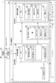
- FIG. 2 is a block diagram showing a functional configuration of the multicopter 1 of this example.
- the functions of the multicopter 1 mainly include a flight control device 10a having a main control unit 11 and a sub control unit 12, a rotor 26 which is a plurality of brushless motors, and an ESC 25 (electric speed controller) which is a drive circuit of the rotor 26. It comprises a receiver 14 connected to the control unit 12 and a battery 19 for supplying power thereto.
- a general flight controller product is used for the main control unit 11 of this example.
- the main control unit 11 includes a main control device 20 which is a microcontroller.
- Main controller 20 controls CPU 21 which is a central processing unit, memory 22 which is a storage device such as a RAM and a ROM / flash memory, and PWM (Pulse Width Modulation: Pulse) which controls the number of rotations of each rotor 26 via ESC 25.
- Width modulation controller 23 is provided.
- the main control unit 11 further includes a flight control sensor group 30 including an IMU 31 (Inertial Measurement Unit: inertial measurement device), a GPS antenna 32, an atmospheric pressure sensor 33, and a geomagnetic sensor 34. It is connected.
- IMU 31 Inertial Measurement Unit: inertial measurement device
- GPS antenna 32 GPS antenna
- atmospheric pressure sensor 33 atmospheric pressure sensor
- geomagnetic sensor 34 geomagnetic sensor
- the IMU 31 mainly includes an acceleration sensor and an angular velocity sensor.
- the GPS antenna 32 is precisely a receiver of a navigation satellite system (NSS).
- the GPS antenna 32 acquires current longitude and latitude values and time information from a Global Navigation Satellite System (GNSS) or a Regional Navigational Satellite System (RNSS).
- the atmospheric pressure sensor 33 is an aspect of the altitude sensor that measures the flight altitude.
- the geomagnetic sensor 34 is an aspect of an azimuth sensor (electronic compass) that specifies the azimuth angle (heading direction) of the nose.
- the main control unit 20 can obtain the position information of its own aircraft including the latitude and longitude during flight, the altitude, and the azimuth angle of the nose as well as the tilt and rotation of the aircraft by these flight control sensors 30. It is done.
- the flight control program 221 adjusts the rotation speed of each rotor 26 based on the information acquired from the flight control sensor group 30, and controls the flight operation of the multicopter 1 while correcting the disturbance of the attitude and position of the airframe.
- a flight plan 223 which is a parameter such as a flight path, a velocity, and an altitude for causing the multicopter 1 to fly is registered.
- the flight control program 221 can autonomously fly in accordance with the flight plan 223 with a start instruction from the operator (transmitter 13) and a predetermined time as a start condition.
- Such an autonomous flight function is called "autopilot" in this example.
- the multicopter 1 of this example is basically assumed to fly by an autopilot, it is also possible for the pilot to steer one by one manually using the transmitter 13.
- the main control unit 11 of this example has an advanced flight control function
- the main control unit of the present invention does not always have to have the same function as the main control unit 11 of this example.
- the main control unit of the present invention can maintain the attitude of the multicopter 1 horizontally in the air, and some sensors are omitted from the flight control sensor group 30 if the elevator, aileron and yaw operations of the airframe can be performed.
- the autopilot function may be omitted.
- the sub control unit 12 includes a sub control device 50 which is a microcontroller.
- the sub control unit 50 includes a CPU 51 which is a central processing unit, a memory 52 which is a storage unit such as a RAM and a ROM / flash memory, and a laser distance sensor 70 which measures a distance to a peripheral d in front of the multicopter 1. have.
- a pseudo signal SP which is a signal of the same system as the signal S output from the receiver 14 that receives the steering signal from the driver (transmitter 13) is generated and generated
- a signal of the same type as the signal S means, for example, PWM, S.I.
- This signal means a serial bus signal such as BUS (registered trademark of Futaba Electronics Co., Ltd.), and a signal method such as PPM (Pulse Position Modulation) or PCM (Pulse Code Modulation).
- the flight control device 10a of this example includes the sub control unit 12, for example, a commercially available flight controller product as in this example is used as the main control unit 10, and the auto pilot function of the flight controller is used. It is possible to realize only unrealizable flight operation with the pseudo signal SP.
- flight controller products to which the receiver can not be connected that is, flight controller products to which pseudo signals can not be input
- flight controller products to which pseudo signals can not be input are considered to be only a very small number of exceptional products, if any. That is, based on the main control unit which has a track record as a finished product, separately prepare only the difference function with the auto pilot function, and input it to the main control unit by disguising this from the signal from the receiver. This makes it possible to efficiently realize special autonomous flight operations.
- a pseudo signal routine 522 which is a generation pattern of the pseudo signal SP with time is registered.
- the operator can call the pseudo signal routine 522 at an arbitrary timing, and can cause the multicopter 1 to perform a desired autonomous flight operation.
- the pseudo signal routine 522 may be executed as a subprogram of the pseudo signal generation program 521 or may be a set of parameters read into the pseudo signal generation program 521.
- the sub control unit 12 of this example can acquire the detection value of the flight control sensor group 30 of the main control unit 11 from the main control unit 11.
- the pseudo signal generation program 521 of the present example can input the main control unit 11 while dynamically changing the pseudo signal SP based on the detection value of the flight control sensor group 30. As a result, the range of the autonomous flight operation that can be realized by the pseudo signal generation program 521 is expanded, and the accuracy of each operation is improved.
- the receiver 14 of this example is connected to the sub control unit 12. Since the receiver 14 is connected to the sub control unit 12, it is possible to easily switch between the manual operation by the driver (transmitter 13) and the control of the aircraft by the pseudo signal SP. When the pilot performs manual steering, the signal S of the receiver input to the sub control unit 12 may be transferred to the main control unit 11 as it is.
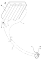
- FIG. 3 is a schematic diagram showing an example of a special autonomous flight operation using the pseudo signal routine 522. As shown in FIG. FIG. 3 is an operation example of photographing the wall surface 90 a of the building 90 at a remote place with the camera 15.
- the flight control device 10a of the multicopter 1 causes the airframe to autonomously fly up to the vicinity of the building 90 by the autopilot function of the main control unit 11, and makes the nose point toward the wall 90a of the building 90 (arrow line a ).
- the sub control unit 12 executes a pseudo signal routine 522 indicated by an arrow line b.
- the pseudo signal routine 522 of this example measures the distance between the camera 90 and the wall surface 90a by measuring the distance between the camera 90 and the wall surface 90a with the laser distance measuring sensor 70, and captures the entire wall surface 90a with the camera 15 It is an operation of. More specifically, starting from the stationary position p of the multicopter 1 (assuming that the stationary position p is a corner at the upper end of the wall 90a), the distance from the wall 90a is made constant while the camera 15 is directed to the wall 90a side. While maintaining it (that is, keeping the detection value of the laser distance measuring sensor 70 constant), the aircraft is level-flyed by the aileron operation.
- the aircraft is lowered by a predetermined amount, and the aircraft is level-flyed in the opposite direction. By repeating this, the entire wall surface 90a is photographed while scanning the wall surface 90a from the top to the bottom.
- the pseudo signal routine 522 is a generation pattern of the pseudo signal SP with time.
- the main control unit 11 recognizes the pseudo signal SP as an output signal from the receiver 14. In other words, it is imagined that the pilot is using the transmitter 13 for manual operation.
- the main control unit 11 controls the attitude of the multicopter 1, the latitude and longitude, the altitude, and the azimuth angle of the nose, and the control of the rotor 26 necessary for the throttle, elevator, aileron and yaw operations. It will be. Therefore, the pseudo signal routine 522 need not take these into consideration. That is, the pseudo signal SP generated by the pseudo signal generation program 521 based on the pseudo signal routine 522 may be a combination of simple instructions that can be expressed even by a general control terminal such as a so-called propo.
- the pseudo signal generation program 521 can dynamically change the content of the pseudo signal SP to be generated based on the detection value of the flight control sensor group 30 or the detection value of the laser distance measuring sensor 70. More specifically, as described above, for example, on the basis of the detection value of the laser distance measuring sensor 70, the pseudo signal SP for keeping the distance from the wall surface 90a constant is generated. By structuring (programming by permutation / branching / repetition), for example, it is possible to determine that the sudden change of the laser distance measuring sensor 70 is over the range of the wall surface 90 a and change the operation.
- the sub control unit 12 After the execution of the pseudo signal routine 522, the sub control unit 12 causes the main control unit 11 to execute an auto pilot operation for returning to the home (arrow line c).
- the autopilot function of the main control unit 11, which is a general flight controller, can only sequentially execute a combination of general-purpose operations, and can dynamically change the operation according to the situation at the time of flight. Can not. That is, in the conventional autopilot function, it is difficult to realize an autonomous flight operation for an unusual special application.
- the flight control apparatus 10a of this example includes the sub-control unit 12 in addition to the main control unit 11, so that complex autonomous flight operation according to a specific application can be performed flexibly and accurately. It is assumed.
- the pseudo signal routine 522 of this example is independent of the auto pilot operation of the main control unit 11, when it is permitted to interrupt the manual pilot (the pseudo signal SP) during the auto pilot by the main control unit 11.
- the pseudo signal routine 522 of this example is independent of the auto pilot operation of the main control unit 11, when it is permitted to interrupt the manual pilot (the pseudo signal SP) during the auto pilot by the main control unit 11.
- a combination of setting the flight route and altitude by the autopilot function of the main control unit 11 and controlling only the azimuth angle of the nose in flight by the sub control unit 12 is also conceivable.
- the sub control part 12 of this example is equipped with the laser ranging sensor 70 as an example of a sensor which is not a peripheral device of the main control part 11, this is not an essential structure.
- the laser distance measuring sensor 70 may be omitted, or another device may be separately mounted.
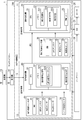
- FIG. 4 is a block diagram showing a functional configuration of the multicopter 1 according to the second embodiment.
- the flight control device 10 b of this example has a flight control sensor group 60 separately from the main control unit 11 in the sub control unit 12.
- the sensors constituting the flight control sensor group 60 are the same as the flight control sensor group 30.
- the sub control unit 12 Since the sub control unit 12 has the flight control sensor group 60 separately from the main control unit 11, the type of flight control sensor group 30 provided on the airframe and the mounting method thereof (internal or external to the main control unit 11) Attached), it is avoided that the function of the sub control part 12 is restricted by the specification of the main control part 11 (transferability of sensor detection value etc.), and the main function of the sub control part 12 is exhibited with various machines. Is possible.
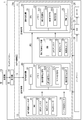
- FIG. 5 is a block diagram showing a functional configuration of the multicopter 1 according to the third embodiment.
- the flight control apparatus 10c of this example is a macro recording unit that is a macro recording unit that records the signal S output from the receiver 14 in the memory 52 of the sub control unit 12.
- the program 523 is registered.
- the pseudo signal routine 522 when creating a new pseudo signal routine 522, by actually operating the airframe and recording the output signal S of the receiver 14 at that time, creating a pseudo signal routine 522 based on this.
- the pseudo signal routine 522 can be efficiently created.
Landscapes
- Engineering & Computer Science (AREA)
- Aviation & Aerospace Engineering (AREA)
- Mechanical Engineering (AREA)
- Remote Sensing (AREA)
- Automation & Control Theory (AREA)
- Physics & Mathematics (AREA)
- General Physics & Mathematics (AREA)
- Traffic Control Systems (AREA)
- Control Of Position, Course, Altitude, Or Attitude Of Moving Bodies (AREA)
Applications Claiming Priority (2)
| Application Number | Priority Date | Filing Date | Title |
|---|---|---|---|
| JP2017131433A JP6547109B2 (ja) | 2017-07-04 | 2017-07-04 | 飛行制御装置およびこれを備える無人航空機 |
| JP2017-131433 | 2017-07-04 |
Publications (1)
| Publication Number | Publication Date |
|---|---|
| WO2019009229A1 true WO2019009229A1 (ja) | 2019-01-10 |
Family
ID=64950140
Family Applications (1)
| Application Number | Title | Priority Date | Filing Date |
|---|---|---|---|
| PCT/JP2018/025008 Ceased WO2019009229A1 (ja) | 2017-07-04 | 2018-07-02 | 飛行制御装置およびこれを備える無人航空機 |
Country Status (2)
| Country | Link |
|---|---|
| JP (1) | JP6547109B2 (enExample) |
| WO (1) | WO2019009229A1 (enExample) |
Families Citing this family (1)
| Publication number | Priority date | Publication date | Assignee | Title |
|---|---|---|---|---|
| JP7790792B1 (ja) * | 2025-03-05 | 2025-12-23 | 株式会社石川エナジーリサーチ | 飛行制御装置および飛行装置 |
Citations (2)
| Publication number | Priority date | Publication date | Assignee | Title |
|---|---|---|---|---|
| US7219861B1 (en) * | 2000-07-06 | 2007-05-22 | Spirit International, Inc. | Guidance system for radio-controlled aircraft |
| JP2017065297A (ja) * | 2015-09-28 | 2017-04-06 | 双葉電子工業株式会社 | 飛行制御装置、飛行制御方法、飛行体 |
-
2017
- 2017-07-04 JP JP2017131433A patent/JP6547109B2/ja active Active
-
2018
- 2018-07-02 WO PCT/JP2018/025008 patent/WO2019009229A1/ja not_active Ceased
Patent Citations (2)
| Publication number | Priority date | Publication date | Assignee | Title |
|---|---|---|---|---|
| US7219861B1 (en) * | 2000-07-06 | 2007-05-22 | Spirit International, Inc. | Guidance system for radio-controlled aircraft |
| JP2017065297A (ja) * | 2015-09-28 | 2017-04-06 | 双葉電子工業株式会社 | 飛行制御装置、飛行制御方法、飛行体 |
Also Published As
| Publication number | Publication date |
|---|---|
| JP2019014317A (ja) | 2019-01-31 |
| JP6547109B2 (ja) | 2019-07-24 |
Similar Documents
| Publication | Publication Date | Title |
|---|---|---|
| US11042074B2 (en) | Flying camera with string assembly for localization and interaction | |
| Sa et al. | Build your own visual-inertial drone: A cost-effective and open-source autonomous drone | |
| CN105793792B (zh) | 无人机的飞行辅助方法和系统、无人机和移动终端 | |
| US10859409B2 (en) | Rotation parameter detection method, encoder, laser radar and unmanned aerial vehicle | |
| CN107356938A (zh) | 一种无人船二维激光雷达自稳装置及其控制方法 | |
| WO2017065103A1 (ja) | 小型無人飛行機の制御方法 | |
| CN104335128A (zh) | 用于用侧风和加速度计偏差估计和补偿来控制多旋翼的旋翼无人机的方法 | |
| US10739792B2 (en) | Trajectory control of a vehicle | |
| JP2019032234A (ja) | 表示装置 | |
| Reizenstein | Position and trajectory control of a quadcopter using PID and LQ controllers | |
| US20210165388A1 (en) | Gimbal rotation control method and apparatus, control device, and movable platform | |
| US20210108920A1 (en) | Magnetic sensor calibration methods, control terminals, and movable platforms | |
| CN108780321A (zh) | 用于设备姿态调整的方法、设备、系统和计算机可读存储介质 | |
| WO2018053816A1 (zh) | 遥控器的控制方法及遥控器 | |
| CN110799922A (zh) | 拍摄控制方法和无人机 | |
| JP6547109B2 (ja) | 飛行制御装置およびこれを備える無人航空機 | |
| US20210208608A1 (en) | Control method, control apparatus, control terminal for unmanned aerial vehicle | |
| JP6579523B2 (ja) | 飛行機能付加装置およびロータユニット | |
| JP2016215958A (ja) | マルチコプター及びマルチコプターシステム | |
| US12105527B2 (en) | System for drone calibration and method therefor | |
| JP2004359002A (ja) | 無人ヘリコプターの自立制御方法及び装置 | |
| JP2022010965A (ja) | 飛行装置 | |
| Meister et al. | Development of a GPS/INS/MAG navigation system and waypoint navigator for a VTOL UAV | |
| JP2019051755A (ja) | 飛行装置の操縦システム | |
| CN114208019A (zh) | 马达控制装置、移动体、马达控制方法以及程序 |
Legal Events
| Date | Code | Title | Description |
|---|---|---|---|
| 121 | Ep: the epo has been informed by wipo that ep was designated in this application |
Ref document number: 18828649 Country of ref document: EP Kind code of ref document: A1 |
|
| NENP | Non-entry into the national phase |
Ref country code: DE |
|
| 122 | Ep: pct application non-entry in european phase |
Ref document number: 18828649 Country of ref document: EP Kind code of ref document: A1 |