WO2019003487A1 - 電動機および電動送風機 - Google Patents
電動機および電動送風機 Download PDFInfo
- Publication number
- WO2019003487A1 WO2019003487A1 PCT/JP2018/004696 JP2018004696W WO2019003487A1 WO 2019003487 A1 WO2019003487 A1 WO 2019003487A1 JP 2018004696 W JP2018004696 W JP 2018004696W WO 2019003487 A1 WO2019003487 A1 WO 2019003487A1
- Authority
- WO
- WIPO (PCT)
- Prior art keywords
- rotor core
- sleeve
- shaft
- axial direction
- rotor
- Prior art date
- Legal status (The legal status is an assumption and is not a legal conclusion. Google has not performed a legal analysis and makes no representation as to the accuracy of the status listed.)
- Ceased
Links
Images







Classifications
-
- F—MECHANICAL ENGINEERING; LIGHTING; HEATING; WEAPONS; BLASTING
- F04—POSITIVE - DISPLACEMENT MACHINES FOR LIQUIDS; PUMPS FOR LIQUIDS OR ELASTIC FLUIDS
- F04D—NON-POSITIVE-DISPLACEMENT PUMPS
- F04D29/00—Details, component parts, or accessories
-
- H—ELECTRICITY
- H02—GENERATION; CONVERSION OR DISTRIBUTION OF ELECTRIC POWER
- H02K—DYNAMO-ELECTRIC MACHINES
- H02K1/00—Details of the magnetic circuit
- H02K1/06—Details of the magnetic circuit characterised by the shape, form or construction
- H02K1/22—Rotating parts of the magnetic circuit
- H02K1/27—Rotor cores with permanent magnets
Definitions
- the present invention relates to an electric motor and an electric blower.
- Patent Document 1 describes a permanent magnet rotor. Permanent magnet rotors are used in electric motors. Moreover, an electric motor is used for an electric blower, for example.
- the permanent magnet rotor described in Patent Document 1 includes a shaft, a permanent magnet, an adhesive, and a fixing material. The permanent magnet is fixed to the shaft by a fixing material provided on the outer peripheral surface of the permanent magnet, and an adhesive positioned between the permanent magnet and the fixing material.
- difference may arise between the position of the central axis of a permanent magnet, and the position of the central axis of a fixing material. This deviation causes variations in mass distribution in the entire permanent magnet rotor. Dispersion of mass distribution in the whole permanent magnet rotor becomes a factor which enlarges vibration at the time of operation of a motor using the permanent magnet rotor. When the vibration increases, the load on the motor increases, and the life of the motor decreases.
- An object of the present invention is to realize an electric motor and an electric blower having a longer life.
- An electric motor comprises a rotatably supported shaft, a rotor core attached to the outer periphery of the shaft and having a plurality of magnetic poles, and a sleeve covering the outer periphery of the rotor core.
- the rotor core and the sleeve abut on a projection plane perpendicular to the axial direction of the above axis via a plurality of convex portions provided symmetrically with respect to the axis.
- An electric blower includes the above-described electric motor, and an impeller attached to a shaft and generating an air flow.
- the rotor core and the sleeve provided in the motor according to the present invention abut on a projection plane perpendicular to the axial direction of the rotatably supported shaft via a plurality of convex portions provided symmetrically with respect to the shaft.
- An electric blower according to the present invention includes the above-described electric motor. For this reason, according to the present invention, the long life of the motor and the electric blower can be realized.
- FIG. 1 is a perspective view showing an appearance of an electric blower of a first embodiment.
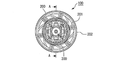
- FIG. 1 is an orthographic view of an electric blower according to a first embodiment as viewed from the axial direction.
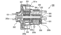
- FIG. 1 is a cross-sectional view of an electric blower of a first embodiment.
- FIG. 1 is a perspective view showing an appearance of a rotor assembly of a first embodiment.
- FIG. 2 is a side view of the rotor assembly of Embodiment 1;
- FIG. 6 is a perspective view showing a state in which a sleeve is removed from the rotor assembly of Embodiment 1;
- FIG. 1 is an exploded perspective view of a rotor of a first embodiment.
- FIG. 1 is an orthographic view of an electric blower according to a first embodiment as viewed from the axial direction.
- FIG. 1 is a cross-sectional view of an electric blower of a first embodiment.
- FIG. 1 is a perspective view showing an appearance of
- FIG. 1 is a cross-sectional view of a rotor of Embodiment 1; It is the elements on larger scale of FIG.
- FIG. 7 is a diagram showing a first example of the arrangement of ribs in the first embodiment.
- FIG. 7 is a diagram showing a second example of the arrangement of ribs in the first embodiment.
- FIG. 7 is a diagram showing a modification of the first embodiment.
- FIG. 7 is a cross-sectional view of a rotor of Embodiment 2;
- FIG. 10 is a diagram showing a modification of the second embodiment.
- FIG. 1 is a perspective view showing the appearance of the electric blower 100 according to the first embodiment.
- FIG. 2 is an orthographic view of the electric blower 100 according to the first embodiment as viewed from the axial direction.
- FIG. 3 is a cross-sectional view of electric blower 100 of the first embodiment.
- FIG. 3 shows an AA cross section of FIG.
- the AA cross section is a cross section passing through the central axis of the electric blower 100.
- the electric blower 100 includes, for example, a brushless motor.
- the brushless motor rotates, for example, at a rated rotation speed of 100,000 [r / min].
- the motor included in the electric blower 100 is not limited to the brushless type, and may rotate at, for example, a rated rotation speed of 30,000 to 50000 [r / min].
- the motor provided in the electric blower 100 includes the frame 200.
- the frame 200 is a member that forms an outer shell of the motor.
- the shape of the frame 200 is, for example, a stepped cylindrical shape.
- One end side of the stepped cylindrical frame 200 is thinner than the other end side. This one end side is the left side in the paper surface of FIG.
- the other end of the frame 200 is the right side in the plane of FIG.
- the motor provided in the electric blower 100 includes a rotor assembly 300 and a stator 500.
- FIG. 4 is a perspective view showing the appearance of the rotor assembly 300 according to the first embodiment.
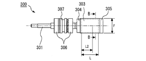
- FIG. 5 is a side view of the rotor assembly 300 according to the first embodiment.
- the rotor assembly 300 comprises a shaft 301, a rotor core 302, a sleeve 303, a first end cap 304, a second end cap 305, a pair of bearings 306 and a spring 307.
- the stator 500 is a member that applies a force to rotate the rotor core 302 to the rotor core 302. A portion of the rotor assembly 300 and the stator 500 are housed in the frame 200, as shown in FIGS.
- the shaft 301 is a member serving as a rotation shaft of the motor.
- the axis 301 is disposed at the center of the internal space of the frame 200.
- the rotor core 302 and the pair of bearings 306 are attached to the shaft 301.
- the rotor core 302 is formed by a permanent magnet.
- the rotor core 302 has a plurality of magnetic poles.
- the rotor core 302 is a member that transmits the force received from the stator 500 to the shaft 301.
- the rotor core 302 is formed, for example, in a cylindrical shape.
- the inner circumferential surface of the rotor core 302 contacts the outer circumferential surface of the shaft 301.
- the inner circumferential surface of the bearing 306 is in contact with the outer circumferential surface of the shaft 301.
- the shaft 301 is rotatably supported via a bearing 306.
- a bearing holding portion 200 a for holding the bearing 306 is formed on the inner peripheral surface of the one end side portion of the frame 200 having a small diameter.
- the bearing 306 is provided such that the outer circumferential surface of the bearing 306 is in contact with the bearing holder.
- a stator holding portion 200b for holding the stator 500 is formed on the inner peripheral surface of the other end portion of the frame 200 having a large diameter.
- the rotor core 302 is provided at a position facing the stator holding portion 200b.
- the stator 500 is provided to surround the rotor core 302.
- the first end cap 304 and the second end cap 305 are members for determining the position of the rotor core 302 with respect to the shaft 301.
- the shape of the first end cap 304 and the second end cap 305 is, for example, a stepped cylindrical shape.
- the first end cap 304 and the second end cap 305 are nonmagnetic.
- the first end cap 304 is disposed closer to the one end than the rotor core 302.
- the first end cap 304 is disposed between the rotor core 302 and the bearing 306.
- the second end cap 305 is disposed closer to the other end than the rotor core 302.
- the second end cap 305 is disposed on the opposite side of the first end cap 304 with respect to the rotor core 302.
- the position of the rotor core 302 relative to the axis 301 is determined by being sandwiched between the first end cap 304 and the second end cap 305.
- the sleeve 303 is a member that covers the outer periphery of the rotor core 302.
- the sleeve 303 is, for example, a cylindrical member.
- the sleeve 303 is a member for fixing the rotor core 302.
- the sleeve 303 covers the entire outer periphery of the rotor core 302.
- the sleeve 303 covers a part of the outer periphery of the first end cap 304 and a part of the outer periphery of the second end cap 305.
- the sleeve 303 of the present embodiment is a nonmagnetic material.
- the sleeve 303 is formed of a composite material including carbon fibers and a resin.
- a composite material containing carbon fiber and a resin is an example of a lightweight, high-strength and heat-resistant material.
- the electric blower 100 includes an impeller 101, a bracket 201, and a cover 202.
- the impeller 101 is a member that generates an air flow by rotating.
- the bracket 201 and the cover 202 are members that form a part of the outer shell of the electric blower 100.
- one end of the shaft 301 passes through the bearing 306 and protrudes outward at one end of the frame 200.
- the impeller 101 is attached to a portion of the shaft 301 that protrudes outward at one end side of the frame 200.
- the pair of bearings 306 is disposed between the impeller 101 and the rotor core 302.
- springs 307 are provided between the bearings 306. The spring 307 is a member that applies a preload to each of the pair of bearings 306.
- the bracket 201 is attached to one end of the frame 200.
- the bracket 201 is provided to surround one end side of the frame 200.
- the cover 202 is attached to one end of the bracket 201.
- the cover 202 is provided to cover the impeller 101.
- an air inlet 202a is formed at a position facing the center of the impeller 101.
- a member such as a guide blade for guiding the air taken in from the air inlet 202a by the impeller 101 is accommodated.
- an exhaust port 201 a is formed on the other end side of the bracket 201.
- the exhaust port 201a is provided radially outward of the shaft 301 than the intake port 202a.
- the exhaust port 201 a is provided radially outward of the shaft 301 than the frame 200.
- the electric blower 100 takes in air from the air inlet 202a and sends out air from the air outlet 201a.
- the frame 200, the bracket 201, and the cover 202 described above are an example of a casing that forms the outer shell of the electric blower 100.
- the rotor assembly 300, the stator 500 and the impeller 101 are housed in this casing.
- the intake port 202a and the exhaust port 201a are formed in this casing.
- a vent 200 c and an exhaust vent 200 d may be formed in the frame 200.
- the vent 200 c is an opening that connects the internal space of the frame 200 and the internal space of the bracket 201.
- the exhaust port 200 d is an opening that connects the internal space of the frame 200 and the outside of the electric blower 100.
- the formation of the vent 200c and the exhaust 200d allows part of the air flowing inside the bracket 201 to flow into the inside of the frame 200 through the vent 200c as shown in FIG.
- the flow of air into the frame 200 cools the rotor assembly 300.
- the air flowing into the inside of the frame 200 is exhausted from the exhaust port 200d.
- FIG. 6 is a perspective view of the rotor assembly 300 according to the first embodiment with the sleeve 303 removed.
- FIG. 7 is an exploded perspective view of the rotor 300 a according to the first embodiment.
- the rotor assembly 300 excluding the bearing 306 and the spring 307 is referred to as a rotor 300a.
- the rotor 300a is composed of a shaft 301, a rotor core 302, a sleeve 303, a first end cap 304, a second end cap 305, an adhesive and the like.
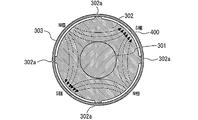
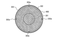
- FIG. 8 is a cross-sectional view of the rotor 300 a of the first embodiment.
- FIG. 9 is a partial enlarged view of FIG. FIG. 8 shows a cross section at the BB position in FIG.
- FIG. 8 shows a cross section through the rotor core 302 and the sleeve 303. This cross section. It is a cross section perpendicular to the axial direction of the shaft 301.
- the positional relationship of each member in the cross section shown in FIG. 8 corresponds to the positional relationship of each member on a projection plane perpendicular to the axial direction of the axis 301.
- the axial direction of the rotor 300 a means the axial direction of the shaft 301.
- the axial direction of the shaft 301 is the axial direction of the cylindrical rotor core 302, the axial direction of the cylindrical sleeve 303, the axial direction of the cylindrical first end cap 304, and the axis of the cylindrical second end cap 305. Match the direction.
- the axial direction of the shaft 301, the axial direction of the cylindrical rotor core 302, the axial direction of the cylindrical sleeve 303, the axial direction of the cylindrical first end cap 304, and the axial direction of the cylindrical second end cap 305 Hereinafter, it is also simply referred to as "axial direction”.
- the direction perpendicular to the axial direction is also simply referred to as “radial direction”.
- a rotor core 302 formed of permanent magnets is attached to the shaft 301 by, for example, press-fitting, bonding, insert molding or the like.
- the central axis of the cylindrical rotor core 302 is, for example, colinear with the central axis of the shaft 301.
- a plurality of ribs 302 a are integrally formed on the rotor core 302.
- the rib 302a protrudes in the radial direction.
- Each of the plurality of ribs 302a is formed along the axial direction.
- the rotor core 302 has, for example, four poles.
- the rotor core 302 is formed with the same number of ribs 302 a as the number of magnetic poles.
- four ribs 302 a are formed on the rotor core 302.
- the plurality of ribs 302a are provided symmetrically with respect to the axis 301, as shown in FIG.
- the angles formed by the ribs 302a are equal to each other.
- the angle between the ribs 302a is 90 degrees.
- the angle between the ribs 302a in the projection plane perpendicular to the axial direction is 120 degrees.
- angles formed by the ribs 302a may not necessarily be all equal.
- the plurality of ribs 302 a may be provided symmetrically with respect to the axis 301.
- the rib 302 a is an example of a convex portion formed to eliminate the bias of the space 400 between the rotor core 302 and the sleeve 303.
- C be the outer diameter of the portion of the cylindrical rotor core 302 where the rib 302 a is not formed.
- the height of the rib 302a is D.
- the height means the dimension in the radial direction. D is, for example, about 0.1 [mm].
- the maximum outer diameter of the rotor core 302 is C + 2D, as shown in FIG.
- the width of the rib 302a is E as shown in FIG.
- the width is a dimension of the rotor core 302 in the circumferential direction. E is, for example, 0.3 [mm] or more.
- the rib 302 a is formed on a part from one end in the axial direction of the rotor core 302 to the other end in the axial direction.
- the axial length of the rotor core 302 is L.
- the rib 302a is formed, for example, in a section from the axial direction end of the rotor core 302 to the length L2.
- the length L2 is, for example, 2/3 or less of the axial length L of the rotor core 302.
- the section in which the rib 302a is formed and the dimensions of the rib 302a are not limited to the example described above.
- the first end cap 304 and the second end cap 305 are attached.
- the first end cap 304 and the second end cap 305 are, for example, press-fit or bonded to the shaft 301.
- the shaft 301 may be formed with a groove or the like for positioning the first end cap 304 and the second end cap 305.
- the rotor core 302 is sandwiched between the first end cap 304 and the second end cap 305.
- the thickness of the first end cap 304 and the thickness of the second end cap 305 are each 2 mm or more, for example. Thickness means the axial dimension.
- the outer diameter of the first end cap 304 and the outer diameter of the second end cap 305 are represented by F. F is greater than or equal to C + 2D described above.
- the sleeve 303 is attached. In the axial direction, for example, the sleeve 303 is attached such that the first end cap 304 and the second end cap 305 are each covered by 1 mm or more.
- the cylindrical sleeve 303 is formed such that the inner diameter of the sleeve 303 is C + 2D.
- the outer diameter of the cylindrical sleeve 303 is, for example, smaller than the inner diameter of the stator 500 by at least 0.4 mm.
- the axial length of the sleeve 303 is, for example, about 5 [mm] longer than the axial length L of the rotor core 302.
- the inner surface of the sleeve 303 whose inner diameter is C + 2D hits the rib 302a.
- the rotor core 302 in which the rib 302 a is formed is held in a state of being pressed into the sleeve 303.
- the rotor core 302 is firmly fixed to the shaft 301 by this adhesive.
- the sleeve 303 is in contact with the rotor core 302 via the rib 302a.
- the rib 302 a is an example of a convex portion provided symmetrically with respect to the axis 301 on a projection plane perpendicular to the axial direction of the axis 301.
- the contact between the rotor core 302 and the sleeve 303 suppresses the displacement between the position of the central axis of the rotor core 302 and the position of the central axis of the sleeve 303.
- variation in mass distribution of the rotor 300a reduces, and the vibration which generate
- the load given to the motor is reduced, and the life of the motor and the electric blower 100 including the motor can be extended.
- the rib 302a eliminates the deviation of the shape of the space 400 between the rotor core 302 and the sleeve 303.
- the adhesive is uniformly filled in the space 400.
- the sleeve 303 can hold the entire rotor core 302 with uniform force. Thereby, for example, the load applied to the rotor core 302 by the centrifugal force generated when the rotor 300a rotates at high speed is effectively suppressed by the sleeve 303. According to the above embodiment, it is possible to further promote the long life of the motor.
- the rib 302 a is formed on a part from one axial end of the rotor core 302 to the other axial end. Thereby, the workability at the time of applying the adhesive to the outer peripheral surface of the rotor core 302 is improved.
- the adhesive may be filled in the space 400 after the sleeve 303 is attached.
- the space 400 is one integral space. Therefore, when the adhesive is filled into the space 400 after the sleeve 303 is attached, the adhesive is easily and uniformly filled in the space 400.
- the adhesive for example, a two-component adhesive is used. According to the above embodiment, since the space 400 is one integral space, the operation of uniformly mixing and filling the two-component adhesive can be easily performed.
- FIG. 10 is a diagram showing a first example of the arrangement of the rib 302a according to the first embodiment.
- the ribs 302 a may be formed between the magnetic poles of the rotor core 302. This prevents the magnetic lines of force in the rotor core 302 from being distorted.
- FIG. 11 is a diagram showing a second example of the disposition of the rib 302a according to the first embodiment.
- the plurality of ribs 302a may be formed at the positions of the plurality of magnetic poles, respectively. As a result, the distance between the magnetic pole and the stator 500 approaches, and the operating efficiency of the motor is improved.
- FIG. 12 shows a modification of the first embodiment.
- the ribs 302a may be formed continuously from one axial end of the rotor core 302 to the other axial end, as shown in FIG.
- the ribs 302 a may be formed to connect one axial end surface of the rotor core 302 to the other axial end surface.
- the rib 302 a may be formed to penetrate the sleeve 303.
- the contact area between the rib 302a and the sleeve 303 becomes larger.
- the rotor 300 a is more firmly held by the sleeve 303.
- the deviation between the position of the central axis of the rotor core 302 and the position of the central axis of the sleeve 303 can be suppressed more reliably.
- FIG. 13 is a cross-sectional view of a rotor 300a of the second embodiment.
- FIG. 14 is a view showing a modification of the second embodiment.
- the configuration of the present embodiment is basically the same as that of the first embodiment.
- ribs 303a are formed instead of the ribs 302a.
- the rib 303 a is integrally formed on the sleeve 303, not on the rotor core 302. Even if the rib 303a is formed on the sleeve 303 as in the present embodiment, the same effect as that of the above-described first embodiment can be obtained. Moreover, the distortion of the magnetic force line in the said rotor core 302 is suppressed because the shape of the rotor core 302 formed of a permanent magnet becomes smooth.
- the rib 303 a may be formed on a part from one end in the axial direction of the sleeve 303 to the other end in the axial direction, as in the rib 302 a of the first embodiment. In this case, the workability when attaching the sleeve 303 and the workability when applying or filling the adhesive become good.
- the rib 303 a may be formed continuously from one end in the axial direction of the sleeve 303 to the other end in the axial direction. In this case, as in the first embodiment, the rotor 300 a is more firmly held by the sleeve 303. Further, the deviation between the position of the central axis of the rotor core 302 and the position of the central axis of the sleeve 303 can be suppressed more reliably.
- the sleeve 303 is a nonmagnetic material as an example.
- the magnetic lines of force in the rotor core 302 are not distorted even if the sleeve 303 rotates around the rotor core 302. In this example, the positioning when attaching the sleeve 303 to the rotor core 302 is facilitated.
- the convex part formed in the sleeve 303 may not be a rib-shaped thing which protrudes in radial direction.
- the contact portion 303 b may be formed on the sleeve 303.
- the shape of the protrusion for bringing the rotor core 302 and the sleeve 303 into contact with each other may be arbitrary.
- the long life of the motor can be realized.
- the electric blower 100 in each embodiment can be used as a drive source of a stick-type vacuum cleaner, for example.
- the electric blower 100 can also be used as a drive source of a hand dryer.
- the life of the product equipped with the electric blower 100 is longer than before.
- the motor according to the present invention may be provided with both the rib 302a and the rib 303a described in the first embodiment.
- the motor according to the present invention, and the convex portion formed separately from the rotor core 302 and the sleeve 303 in each of the above embodiments may be provided.
- the electric motor and the electric blower according to the present disclosure are used as drive sources of arbitrary products such as, for example, a vacuum cleaner and a hand dryer.
Landscapes
- Engineering & Computer Science (AREA)
- Power Engineering (AREA)
- Mechanical Engineering (AREA)
- General Engineering & Computer Science (AREA)
- Structures Of Non-Positive Displacement Pumps (AREA)
- Connection Of Motors, Electrical Generators, Mechanical Devices, And The Like (AREA)
- Permanent Field Magnets Of Synchronous Machinery (AREA)
- Iron Core Of Rotating Electric Machines (AREA)
Abstract
より寿命の長い電動機および電動送風機を実現する。本開示に係る電動機は、回転可能に支持される軸(301)と、軸(301)の外周に取り付けられ、複数の磁極を有するローターコア(302)と、ローターコア(302)の外周を覆うスリーブ(303)と、を備える。ローターコア(302)とスリーブ(303)とは、軸(301)に対して対称に設けられた複数のリブ(302a)を介して当接する。本開示に係る電動送風機は、上記の電動機を備える。
Description
本発明は、電動機および電動送風機に関するものである。
特許文献1に、永久磁石回転子が記載されている。永久磁石回転子は、電動機に用いられる。また、電動機は、例えば、電動送風機に用いられる。特許文献1に記載された永久磁石回転子は、シャフト、永久磁石、接着剤および固定材を備える。永久磁石は、当該永久磁石の外周面に設けられた固定材と、当該永久磁石と当該固定材との間に位置する接着剤とによって、シャフトに固定される。
特許文献1においては、永久磁石の中心軸の位置と固定材の中心軸の位置との間にずれが生じる場合がある。このずれにより、永久磁石回転子全体における質量分布にばらつきが生じる。永久磁石回転子全体における質量分布のばらつきは、当該永久磁石回転子が用いられた電動機が運転する際の振動を大きくする要因になる。振動が大きくなった場合、電動機への負荷が大きくなり、当該電動機の寿命が短くなってしまう。
本発明は、上記のような課題を解決するためになされたものである。本発明の目的は、より寿命の長い電動機および電動送風機を実現することである。
本発明に係る電動機は、回転可能に支持される軸と、軸の外周に取り付けられ、複数の磁極を有するローターコアと、ローターコアの外周を覆うスリーブと、を備える。ローターコアとスリーブとは、上記の軸の軸方向に垂直な投影面において当該軸に対して対称に設けられた複数の凸部を介して当接する。本発明に係る電動送風機は、上記の電動機と、軸に取り付けられ、気流を発生させるインペラと、を備える。
本発明に係る電動機が備えるローターコアとスリーブとは、回転可能に支持された軸の軸方向に垂直な投影面において当該軸に対して対称に設けられた複数の凸部を介して当接する。また、本発明に係る電動送風機は、上記の電動機を備える。このため、本発明によれば、電動機および電動送風機の長寿命化が実現される。
以下、図面を参照して、実施の形態について説明する。各図における同一の符号は、同一の部分または相当する部分を示す。本開示では、重複する説明については、適宜に簡略化または省略する。なお、本発明は、以下の各実施の形態に開示される構成のあらゆる組み合わせを含み得るものである。
実施の形態1.
図1は、実施の形態1の電動送風機100の外観を示す斜視図である。図2は、実施の形態1の電動送風機100を軸方向から見た正投影図である。図3は、実施の形態1の電動送風機100の断面図である。図3は、図2のA―A断面を示している。このA―A断面は、電動送風機100の中心軸を通る断面である。
図1は、実施の形態1の電動送風機100の外観を示す斜視図である。図2は、実施の形態1の電動送風機100を軸方向から見た正投影図である。図3は、実施の形態1の電動送風機100の断面図である。図3は、図2のA―A断面を示している。このA―A断面は、電動送風機100の中心軸を通る断面である。
電動送風機100は、一例として、ブラシレス型の電動機を備える。ブラシレス型の電動機は、例えば、定格回転数100000[r/min]で回転する。なお、電動送風機100が備える電動機は、ブラシレス型に限定されるものではなく、例えば、定格回転数30000~50000[r/min]で回転するものであってもよい。
電動送風機100が備える電動機は、フレーム200を備える。フレーム200は、電動機の外殻を形成する部材である。フレーム200の形状は、例えば、段付きの円筒状である。段付きの円筒状のフレーム200の一端側は、他端側よりも細い。この一端側は、図3の紙面における左側である。フレーム200の他端側は、図3の紙面における右側である。
電動送風機100が備える電動機は、ローターアセンブリ300およびステーター500を備える。図4は、実施の形態1のローターアセンブリ300の外観を示す斜視図である。図5は、実施の形態1のローターアセンブリ300の側面図である。
ローターアセンブリ300は、軸301、ローターコア302、スリーブ303、第1エンドキャップ304、第2エンドキャップ305、1対の軸受306およびばね307を有する。ステーター500は、ローターコア302を回転させる力を当該ローターコア302へ付与する部材である。ローターアセンブリ300の一部およびステーター500は、図1から図3に示すように、フレーム200に収容される。
軸301は、電動機の回転軸となる部材である。軸301は、フレーム200の内部空間の中央部に配置される。ローターコア302および一対の軸受306は、この軸301に取り付けられる。ローターコア302は、永久磁石によって形成される。ローターコア302は、複数の磁極を有する。ローターコア302は、ステーター500から受けた力を軸301へ伝える部材である。ローターコア302は、例えば、円筒状に形成される。ローターコア302の内周面は、軸301の外周面に接触する。また、軸受306の内周面は、軸301の外周面に接触する。軸301は、軸受306を介し、回転可能に支持される。
上述したように、段付きの円筒状のフレーム200の一端側は、他端側よりも細い。フレーム200の径が小さい一端側部分の内周面には、軸受306を保持する軸受保持部200aが形成される。軸受306は、当該軸受306の外周面が軸受保持部に接触するように設けられる。また、フレーム200の径が大きい他端側部分の内周面には、ステーター500を保持するステーター保持部200bが形成される。ローターコア302は、このステーター保持部200bに対向する位置に設けられる。ステーター500は、ローターコア302を取り囲むように設けられる。
第1エンドキャップ304および第2エンドキャップ305は、軸301に対するローターコア302の位置を決めるための部材である。第1エンドキャップ304および第2エンドキャップ305の形状は、例えば、段付きの円筒状である。第1エンドキャップ304および第2エンドキャップ305は、非磁性体である。
第1エンドキャップ304は、ローターコア302よりも上記一端側へ配置される。第1エンドキャップ304は、ローターコア302と軸受306との間に配置される。第2エンドキャップ305は、ローターコア302よりも上記他端側へ配置される。第2エンドキャップ305は、ローターコア302を基準として第1エンドキャップ304の反対側に配置される。軸301に対するローターコア302の位置は、第1エンドキャップ304と第2エンドキャップ305とに挟まれることで決められる。
また、スリーブ303は、ローターコア302の外周を覆う部材である。スリーブ303は、例えば、円筒状の部材である。スリーブ303は、ローターコア302を固定するための部材である。本実施の形態において、スリーブ303は、ローターコア302の外周全体を覆う。または、スリーブ303は、第1エンドキャップ304の外周の一部と第2エンドキャップ305の外周の一部とを覆う。ローターコア302とスリーブ303との間には、接着剤がある。接着剤により、ローターコア302が強く固定される。
本実施の形態のスリーブ303は、非磁性体である。一例として、スリーブ303は、カーボン繊維と樹脂とを含む複合材料によって形成される。カーボン繊維と樹脂とを含む複合材料は、軽量で高強度かつ耐熱性を有する材料の一例である。
また、電動送風機100は、インペラ101、ブラケット201およびカバー202を備える。インペラ101は、回転することで気流を発生させる部材である。ブラケット201およびカバー202は、電動送風機100の外殻の一部を形成する部材である。
図3に示すように、軸301の一端側は、軸受306を貫通し、フレーム200の一端側外方へ突出する。インペラ101は、軸301のうち、フレーム200の一端側外方へ突出した部分に取り付けられる。本実施の形態において、一対の軸受306は、このインペラ101とローターコア302との間に配置される。また、軸受306同士の間には、ばね307が設けられている。ばね307は、一対の軸受306の各々に予圧を付与する部材である。
ブラケット201は、フレーム200の一端側に取り付けられる。ブラケット201は、フレーム200の一端側を囲うように設けられる。カバー202は、ブラケット201の一端側に取り付けられる。カバー202は、インペラ101を覆うように設けられる。カバー202の一端側には、インペラ101の中心に対向する位置に吸気口202aが形成される。ブラケット201には、インペラ101によって吸気口202aから取り込まれた空気を案内する案内羽根等の部材が収容される。
また、ブラケット201の他端側には、排気口201aが形成される。排気口201aは、吸気口202aよりも軸301の径方向外方に設けられる。排気口201aは、フレーム200よりも軸301の径方向外方に設けられる。電動送風機100は、吸気口202aから空気を取り込み、排気口201aから空気を送り出す。
上記したフレーム200、ブラケット201およびカバー202は、電動送風機100の外殻を形成するケーシングの一例である。本実施の形態において、ローターアセンブリ300、ステーター500およびインペラ101は、このケーシングに収容される。また、吸気口202aおよび排気口201aは、このケーシングに形成されている。
ここで、図3を参照し、電動送風機100の動作時における空気の流れについて説明する。電動送風機100の動作時における空気の流れの一部は、図3中に白抜き矢印で示している。電動送風機100の動作時には、ステーター500からローターコア302に回転力が付与される。これにより、ローターコア302および軸301が回転する。また、軸301に取り付けられたインペラ101が回転する。
インペラ101が回転すると、吸気口202aにおける圧力が負圧になる。これにより、吸気口202aからカバー202内へと空気が吸い込まれる。吸い込まれた空気は、インペラ101の中心部から外周へと送られる。インペラ101の外周へ送られた空気は、ブラケット201の内部を流れ、排気口201aから吹き出される。
また、図3に示すように、フレーム200には、通気口200cおよび排気口200dが形成されてもよい。通気口200cは、フレーム200の内部空間とブラケット201の内部空間とをつなぐ開口である。排気口200dは、フレーム200の内部空間と電動送風機100の外部とをつなぐ開口である。通気口200cおよび排気口200dが形成されることで、ブラケット201の内部を流れる空気の一部は、図3に示すように、当該通気口200cを介してフレーム200の内部へ流れこむ。フレーム200の内部へ空気が流れ込むことで、ローターアセンブリ300が冷却される。フレーム200の内部へ流れ込んだ空気は、排気口200dから排出される。
次に、図6から図9をさらに参照し、本実施の形態のローターアセンブリ300について、より詳細に説明する。図6は、実施の形態1のローターアセンブリ300からスリーブ303を外した状態を示す斜視図である。図7は、実施の形態1のローター300aの分解斜視図である。本実施の形態では、ローターアセンブリ300から、軸受306およびばね307を除いたものを、ローター300aと称する。ローター300aは、軸301、ローターコア302、スリーブ303、第1エンドキャップ304、第2エンドキャップ305および接着剤等からなる。
また、図8は、実施の形態1のローター300aの断面図である。図9は、図8の部分拡大図である。図8は、図5におけるB-B位置での断面を示している。図8は、ローターコア302およびスリーブ303を通る断面を示している。この断面は。軸301の軸方向に垂直な断面である。図8に示す断面における各部材の位置関係は、軸301の軸方向に垂直な投影面における各部材の位置関係に対応する。
本実施の形態において、ローター300aの軸方向とは、軸301の軸方向を意味する。また、軸301の軸方向は、円筒状のローターコア302の軸方向、円筒状のスリーブ303の軸方向、円筒状の第1エンドキャップ304の軸方向および円筒状の第2エンドキャップ305の軸方向と一致する。軸301の軸方向、円筒状のローターコア302の軸方向、円筒状のスリーブ303の軸方向、円筒状の第1エンドキャップ304の軸方向および円筒状の第2エンドキャップ305の軸方向を、以下では単に「軸方向」とも称する。また、この軸方向に垂直な方向を、単に、「径方向」とも称する。
各図を参照し、ローター300aの組み立て手順およびローター300aのより詳細な構成について説明する。まず、永久磁石によって形成されたローターコア302が、例えば、圧入、接着、インサート成形等によって、軸301に取り付けられる。図8に示すように、円筒状のローターコア302の中心軸は、一例として、軸301の中心軸と同一直線状にある。このローターコア302には、図6から図9に示すように、複数のリブ302aが一体的に形成される。
リブ302aは、径方向に突出する。複数のリブ302aは、それぞれ、軸方向に沿って形成される。ローターコア302は、例えば、4極の磁極を有する。一例として、ローターコア302には、磁極の数と同数のリブ302aが形成される。ローターコア302には、例えば、4つのリブ302aが形成される。
これら複数のリブ302aは、図8に示すように、軸301に対して対称に設けられる。例えば、軸方向に垂直な投影面において、リブ302a同士がなす角度は、それぞれ等しくなる。リブ302aが4つの場合、軸方向に垂直な投影面において、リブ302a同士がなす角度は、90度になる。また、リブ302aが3つの場合、軸方向に垂直な投影面においてリブ302a同士がなす角度は、120度になる。
なお、リブ302a同士がなす角度は、必ずしも全て等しくなくてもよい。複数のリブ302aは、軸301に対して対称に設けられればよい。リブ302aは、ローターコア302とスリーブ303との間の空間400の偏りをなくすために形成される凸部の一例である。
図8に示すように、円筒状のローターコア302のうち、リブ302aが形成されていない部分の外径をCとする。リブ302aの高さをDとする。この高さとは、径方向の寸法を意味する。Dは、例えば、0.1[mm]程度である。ローターコア302の最大外径は、図8に示すように、C+2Dである。また、リブ302aの幅を、図9に示すように、Eとする。この幅とは、ローターコア302の周方向の寸法である。Eは、例えば、0.3[mm]以上である。
また、本実施の形態においてリブ302aは、ローターコア302の軸方向一端から軸方向他端までの一部に形成される。ここで、ローターコア302の軸方向長さをLとする。リブ302aは、例えば、ローターコア302の軸方向一端から長さL2の区間に形成される。長さL2は、例えば、ローターコア302の軸方向長さLの2/3以下である。なお、リブ302aが形成される区間およびリブ302aの寸法は、上記した例に限られない。
図7に示すように、軸301にローターコア302が取り付けられた後、第1エンドキャップ304および第2エンドキャップ305が取りつけられる。第1エンドキャップ304および第2エンドキャップ305は、例えば、軸301に圧入または接着される。軸301には、第1エンドキャップ304および第2エンドキャップ305の位置を決めるための溝等が形成されてもよい。上述したように、ローターコア302は、第1エンドキャップ304と第2エンドキャップ305とに挟まれる。
第1エンドキャップ304の厚さおよび第2エンドキャップ305の厚さは、それぞれ、例えば、2[mm]以上である。厚さとは、軸方向寸法を意味する。ここで、第1エンドキャップ304の外径および第2エンドキャップ305の外径を、Fとする。Fは、上述したC+2D以上である。
軸301に第1エンドキャップ304および第2エンドキャップ305が取りつけられた後、ローターコア302の外周面に接着剤が塗布される。このとき、接着剤は、リブ302aには塗られないことが好ましい。接着剤がローターコア302に塗布された後、スリーブ303が取り付けられる。軸方向において、スリーブ303は、例えば、第1エンドキャップ304および第2エンドキャップ305がそれぞれ1[mm]以上覆われるように取り付けられる。
ここで、円筒状のスリーブ303は、当該スリーブ303の内径がC+2Dになるように形成される。円筒状のスリーブ303の外径は、例えば、ステーター500の内径よりも0.4[mm]以上小さい。また、スリーブ303の軸方向の長さは、例えば、ローターコア302の軸方向長さLよりも5[mm]程度長い。
内径がC+2Dであるスリーブ303の内面は、リブ302aに当たる。リブ302aが形成されたローターコア302は、スリーブ303に圧入された状態で保持される。また、ローターコア302とスリーブ303との間の空間400には接着剤がある。この接着剤により、ローターコア302は、軸301に対して強固に固定される。
上記の実施の形態において、スリーブ303は、リブ302aを介してローターコア302に当接している。リブ302aは、軸301の軸方向に垂直な投影面において軸301に対して対称に設けられた凸部の一例である。ローターコア302とスリーブ303とが当接することで、ローターコア302の中心軸の位置とスリーブ303の中心軸の位置とのずれが抑えられる。これにより、ローター300aの質量分布のばらつきが低減し、ローター300aが回転した際に発生する振動が抑制される。上記の実施の形態であれば、電動機に与えられる負荷が低減し、電動機およびこの電動機を備えた電動送風機100の長寿命化が実現される。
また、リブ302aにより、ローターコア302とスリーブ303との間の空間400の形状の偏りがなくなる。これにより、空間400内には、接着剤が均一に満ちる。上記の実施の形態であれば、スリーブ303は、ローターコア302の全体を均一な力で保持することができる。これにより、例えば、ローター300aが高速で回転した際に発生する遠心力によってローターコア302に与えられる負荷が、スリーブ303によって効果的に抑制される。上記の実施の形態であれば、電動機の長寿命化をより促進することができる。
上記の実施の形態において、リブ302aは、ローターコア302の軸方向一端から軸方向他端までの一部に形成されている。これにより、ローターコア302の外周面に接着剤を塗布する際の作業性が良好になる。
なお接着剤は、スリーブ303が取り付けられた後に空間400に充填されてもよい。上記の実施の形態では、リブ302aがローターコア302の軸方向一端から軸方向他端までの一部に形成されるため、空間400は一つの一体的な空間である。このため、スリーブ303が取り付けられた後に接着剤を空間400に充填する場合、接着剤は当該空間400に容易に均一に充填される。また、接着剤には、例えば2液性のものが用いられる。上記の実施の形態であれば、空間400が一つの一体的な空間であるため、2液性の接着剤を均一に混合しつつ充填する作業が容易に可能となる。
図10は、実施の形態1のリブ302aの配置の第1の例を示す図である。図10に示すように、リブ302aは、ローターコア302の磁極同士の間に形成されてもよい。これにより、ローターコア302における磁力線が歪んでしまうことが防止される。また、図11は、実施の形態1のリブ302aの配置の第2の例を示す図である。複数のリブ302aは、それぞれ、複数の磁極の位置に形成されてもよい。これにより、磁極とステーター500との距離が近づき、電動機の運転効率がよくなる。
図12は、実施の形態1の変形例を示す図である。リブ302aは、図12に示すように、ローターコア302の軸方向一端から軸方向他端にかけて連続して形成されてもよい。言い換えると、リブ302aは、ローターコア302の軸方向一側端面から軸方向他側端面とをつなぐように形成されてもよい。リブ302aは、スリーブ303を貫通するように形成されてもよい。本変形例であれば、リブ302aとスリーブ303との接触面積がより大きくなる。これにより、ローター300aは、スリーブ303によってより強固に保持される。また、ローターコア302の中心軸の位置とスリーブ303の中心軸の位置とのずれが、より確実に抑えられる。
実施の形態2.
次に、実施の形態2について説明する。実施の形態2については、上述した実施の形態1との相違点を中心に説明する。実施の形態1と同一または相当する部分については、同じ符号を付し、また、説明を簡略化および省略する。図13は、実施の形態2のローターの300aの断面図である。また、図14は、実施の形態2の変形例を示す図である。本実施の形態の構成は、基本的に実施の形態1と同様である。
次に、実施の形態2について説明する。実施の形態2については、上述した実施の形態1との相違点を中心に説明する。実施の形態1と同一または相当する部分については、同じ符号を付し、また、説明を簡略化および省略する。図13は、実施の形態2のローターの300aの断面図である。また、図14は、実施の形態2の変形例を示す図である。本実施の形態の構成は、基本的に実施の形態1と同様である。
本実施の形態では、リブ302aの代わりにリブ303aが形成される。リブ303aは、ローターコア302ではなくスリーブ303に一体的に形成される。本実施の形態のように、スリーブ303にリブ303aが形成されても、上記の実施の形態1と同様の効果が得られる。また、永久磁石によって形成されるローターコア302の形状が滑らかになることで、当該ローターコア302における磁力線の歪みが抑制される。
リブ303aは、実施の形態1のリブ302aと同様、スリーブ303の軸方向一端から軸方向他端までの一部に形成されてもよい。この場合、スリーブ303を取り付ける際の作業性と接着剤を塗布または充填する際の作業性が良好になる。また、リブ303aは、スリーブ303の軸方向一端から軸方向他端にかけて連続して形成されてもよい。この場合、実施の形態1と同様、ローター300aは、スリーブ303によってより強固に保持される。また、ローターコア302の中心軸の位置とスリーブ303の中心軸の位置とのずれが、より確実に抑えられる。
また、スリーブ303は、一例として非磁性体である。非磁性体であるスリーブ303にリブ303aが形成された場合、ローターコア302を中心として当該スリーブ303が回転しても、ローターコア302における磁力線が歪まない。本例であれば、スリーブ303をローターコア302に対して取り付ける際の位置決めが容易になる。
また、スリーブ303に形成される凸部は、径方向に突出するリブ状のものでなくてもよい。例えば、スリーブ303には、図14に示すように、接触部303bが形成されてもよい。ローターコア302とスリーブ303とを当接させる凸部の形状は、任意のものでもよい。
以上説明した実施の形態1または実施の形態2によれば、電動機の長寿命化を実現することができる。上記の各実施の形態によれば、特に、DCブラシレスモーターのように高回転の電動機の長寿命化を効果的に実現することができる。また、各実施の形態における電動送風機100は、例えば、スティック型の電気掃除機の駆動源として使用できる。電動送風機100は、手乾燥機の駆動源としても使用できる。電動送風機100を搭載した製品の寿命は、従来に比べてより長くなる。なお、本発明に係る電動機は、実施の形態1で説明したリブ302aとリブ303aとを両方備えていてもよい。また、本発明に係る電動機、上記の各実施の形態におけるローターコア302およびスリーブ303とは別体として形成された凸部を備えていてもよい。
本開示に係る電動機および電動送風機は、例えば、電気掃除機および手乾燥機等の任意製品の駆動源として利用される。
100 電動送風機、 101 インペラ、 200 フレーム、 200a 軸受保持部、 200b ステーター保持部、 200c 通気口、 200d 排気口、 201 ブラケット、 201a 排気口、 202 カバー、 202a 吸気口、 300 ローターアセンブリ、 300a ローター、 301 軸、 302 ローターコア、 302a リブ、 303 スリーブ、 303a リブ、 303b 接触部、 304 第1エンドキャップ、 305 第2エンドキャップ、 306 軸受、 307 ばね、 400 空間、 500 ステーター
Claims (11)
- 回転可能に支持される軸と、
前記軸の外周に取り付けられ、複数の磁極を有するローターコアと、
前記ローターコアの外周を覆うスリーブと、
を備え、
前記ローターコアと前記スリーブとは、前記軸の軸方向に垂直な投影面において前記軸に対して対称に設けられた複数の凸部を介して当接する電動機。 - 前記凸部は前記ローターコアと一体的に形成されている請求項1に記載の電動機。
- 前記凸部は、前記ローターコアの軸方向一端から軸方向他端までの一部に形成されている請求項2に記載の電動機。
- 前記凸部は、前記ローターコアの軸方向一端から軸方向他端にかけて連続して形成されている請求項2に記載の電動機。
- 前記凸部は、前記複数の磁極同士の間に形成されている請求項2から請求項4の何れか1項に記載の電動機。
- 前記複数の凸部は、それぞれ、前記複数の磁極の位置に形成されている請求項2から請求項4の何れか1項に記載の電動機。
- 前記凸部は、前記スリーブと一体的に形成されている請求項1に記載の電動機。
- 前記凸部は、前記スリーブの軸方向一端から軸方向他端までの一部に形成されている請求項7に記載の電動機。
- 前記凸部は、前記スリーブの軸方向一端から軸方向他端にかけて連続して形成されている請求項7に記載の電動機。
- 前記スリーブは、非磁性体である請求項7から請求項9の何れか1項に記載の電動機。
- 請求項1から請求項10の何れか1項に記載された電動機と、
前記軸に取り付けられ、気流を発生させるインペラと、
を備えた電動送風機。
Priority Applications (1)
| Application Number | Priority Date | Filing Date | Title |
|---|---|---|---|
| JP2019526135A JP6822565B2 (ja) | 2017-06-28 | 2018-02-09 | 電動機および電動送風機 |
Applications Claiming Priority (2)
| Application Number | Priority Date | Filing Date | Title |
|---|---|---|---|
| JP2017126392 | 2017-06-28 | ||
| JP2017-126392 | 2017-06-28 |
Publications (1)
| Publication Number | Publication Date |
|---|---|
| WO2019003487A1 true WO2019003487A1 (ja) | 2019-01-03 |
Family
ID=64740524
Family Applications (1)
| Application Number | Title | Priority Date | Filing Date |
|---|---|---|---|
| PCT/JP2018/004696 Ceased WO2019003487A1 (ja) | 2017-06-28 | 2018-02-09 | 電動機および電動送風機 |
Country Status (2)
| Country | Link |
|---|---|
| JP (1) | JP6822565B2 (ja) |
| WO (1) | WO2019003487A1 (ja) |
Cited By (3)
| Publication number | Priority date | Publication date | Assignee | Title |
|---|---|---|---|---|
| JP2019110680A (ja) * | 2017-12-19 | 2019-07-04 | 三菱電機株式会社 | 回転電機のロータの製造方法及びスリーブ接着装置 |
| JP2020162377A (ja) * | 2019-03-28 | 2020-10-01 | 三菱電機株式会社 | 電動機、この電動機を備えた電動送風機及びこの電動送風機を備えた電気機器 |
| CN120955982A (zh) * | 2025-08-04 | 2025-11-14 | 威海克莱特菲尔风机股份有限公司 | 可除尘降温的电机及其设计方法 |
Citations (7)
| Publication number | Priority date | Publication date | Assignee | Title |
|---|---|---|---|---|
| JPS56106076U (ja) * | 1980-01-17 | 1981-08-18 | ||
| JPS62162793A (ja) * | 1986-01-14 | 1987-07-18 | Matsushita Electric Ind Co Ltd | 電動送風機 |
| JPH0631350A (ja) * | 1992-07-13 | 1994-02-08 | Yasunori Nakano | 中空部材の凹部形成方法 |
| JP2001037122A (ja) * | 1999-07-23 | 2001-02-09 | Sankyo Seiki Mfg Co Ltd | 電動機の回転子 |
| WO2007080888A1 (ja) * | 2006-01-10 | 2007-07-19 | Mitsuba Corporation | 回転電機 |
| JP2010206939A (ja) * | 2009-03-03 | 2010-09-16 | Nsk Ltd | ブラシレスモータ用ロータ、ブラシレスモータ及び電動パワーステアリング装置、並びにブラシレスモータ用ロータの製造方法 |
| JP2015100202A (ja) * | 2013-11-19 | 2015-05-28 | 日本電産サンキョー株式会社 | ロータ、モータ、およびロータの製造方法 |
-
2018
- 2018-02-09 JP JP2019526135A patent/JP6822565B2/ja active Active
- 2018-02-09 WO PCT/JP2018/004696 patent/WO2019003487A1/ja not_active Ceased
Patent Citations (7)
| Publication number | Priority date | Publication date | Assignee | Title |
|---|---|---|---|---|
| JPS56106076U (ja) * | 1980-01-17 | 1981-08-18 | ||
| JPS62162793A (ja) * | 1986-01-14 | 1987-07-18 | Matsushita Electric Ind Co Ltd | 電動送風機 |
| JPH0631350A (ja) * | 1992-07-13 | 1994-02-08 | Yasunori Nakano | 中空部材の凹部形成方法 |
| JP2001037122A (ja) * | 1999-07-23 | 2001-02-09 | Sankyo Seiki Mfg Co Ltd | 電動機の回転子 |
| WO2007080888A1 (ja) * | 2006-01-10 | 2007-07-19 | Mitsuba Corporation | 回転電機 |
| JP2010206939A (ja) * | 2009-03-03 | 2010-09-16 | Nsk Ltd | ブラシレスモータ用ロータ、ブラシレスモータ及び電動パワーステアリング装置、並びにブラシレスモータ用ロータの製造方法 |
| JP2015100202A (ja) * | 2013-11-19 | 2015-05-28 | 日本電産サンキョー株式会社 | ロータ、モータ、およびロータの製造方法 |
Cited By (5)
| Publication number | Priority date | Publication date | Assignee | Title |
|---|---|---|---|---|
| JP2019110680A (ja) * | 2017-12-19 | 2019-07-04 | 三菱電機株式会社 | 回転電機のロータの製造方法及びスリーブ接着装置 |
| JP6994926B2 (ja) | 2017-12-19 | 2022-01-14 | 三菱電機株式会社 | 回転電機のロータの製造方法及びスリーブ接着装置 |
| JP2020162377A (ja) * | 2019-03-28 | 2020-10-01 | 三菱電機株式会社 | 電動機、この電動機を備えた電動送風機及びこの電動送風機を備えた電気機器 |
| JP7131457B2 (ja) | 2019-03-28 | 2022-09-06 | 三菱電機株式会社 | 電動機の製造方法 |
| CN120955982A (zh) * | 2025-08-04 | 2025-11-14 | 威海克莱特菲尔风机股份有限公司 | 可除尘降温的电机及其设计方法 |
Also Published As
| Publication number | Publication date |
|---|---|
| JPWO2019003487A1 (ja) | 2019-11-07 |
| JP6822565B2 (ja) | 2021-01-27 |
Similar Documents
| Publication | Publication Date | Title |
|---|---|---|
| JP7090767B2 (ja) | モータ、送風機、電気掃除機および手乾燥装置 | |
| US8933605B2 (en) | Brushless motor | |
| CN104811005A (zh) | 电动机以及转子、转子的制造方法 | |
| EP3760877A1 (en) | Electric blower, electric vacuum cleaner and hand dryer | |
| KR20130110440A (ko) | 임펠러 및 이를 포함한 진공청소기 모터 어셈블리 | |
| WO2019003487A1 (ja) | 電動機および電動送風機 | |
| US11268532B2 (en) | Electric blower, electric vacuum cleaner, and hand dryer | |
| TWM540428U (zh) | 流體產生裝置及電器設備 | |
| JP6271268B2 (ja) | 電動送風機およびその製造方法 | |
| KR102200078B1 (ko) | 팬 모터 | |
| TW201631866A (zh) | 無刷馬達及具備其之電動自行車 | |
| JP6804834B2 (ja) | 電動送風機 | |
| JP2022043426A (ja) | 回転機器 | |
| JP2014042441A (ja) | スイッチドリラクタンスモータアセンブリ | |
| JP6470055B2 (ja) | 電動送風機およびそれを用いた電気掃除機 | |
| WO2020174878A1 (ja) | 電動機及び電動送風機 | |
| JP2017008789A (ja) | ファン及びドライヤー | |
| KR20200101743A (ko) | 팬 모터 | |
| CN114135502A (zh) | 旋转设备 | |
| JP2023173205A (ja) | 電動機及び電動送風機 | |
| WO2020195398A1 (ja) | モータ | |
| JP6054207B2 (ja) | 電動送風機 | |
| JP5393291B2 (ja) | モータ装置 | |
| JPWO2019211965A1 (ja) | 電動機及び電動送風機 | |
| JP2017061889A (ja) | 電動送風機 |
Legal Events
| Date | Code | Title | Description |
|---|---|---|---|
| 121 | Ep: the epo has been informed by wipo that ep was designated in this application |
Ref document number: 18824082 Country of ref document: EP Kind code of ref document: A1 |
|
| ENP | Entry into the national phase |
Ref document number: 2019526135 Country of ref document: JP Kind code of ref document: A |
|
| NENP | Non-entry into the national phase |
Ref country code: DE |
|
| 122 | Ep: pct application non-entry in european phase |
Ref document number: 18824082 Country of ref document: EP Kind code of ref document: A1 |