WO2018235804A1 - 分注装置および液体の分注方法および細胞の分注方法 - Google Patents
分注装置および液体の分注方法および細胞の分注方法 Download PDFInfo
- Publication number
- WO2018235804A1 WO2018235804A1 PCT/JP2018/023242 JP2018023242W WO2018235804A1 WO 2018235804 A1 WO2018235804 A1 WO 2018235804A1 JP 2018023242 W JP2018023242 W JP 2018023242W WO 2018235804 A1 WO2018235804 A1 WO 2018235804A1
- Authority
- WO
- WIPO (PCT)
- Prior art keywords
- dispensing
- liquid
- elastic member
- tubular elastic
- tubular
- Prior art date
- Legal status (The legal status is an assumption and is not a legal conclusion. Google has not performed a legal analysis and makes no representation as to the accuracy of the status listed.)
- Ceased
Links
Images




Classifications
-
- B—PERFORMING OPERATIONS; TRANSPORTING
- B01—PHYSICAL OR CHEMICAL PROCESSES OR APPARATUS IN GENERAL
- B01L—CHEMICAL OR PHYSICAL LABORATORY APPARATUS FOR GENERAL USE
- B01L3/00—Containers or dishes for laboratory use, e.g. laboratory glassware; Droppers
- B01L3/02—Burettes; Pipettes
- B01L3/021—Pipettes, i.e. with only one conduit for withdrawing and redistributing liquids
- B01L3/0217—Pipettes, i.e. with only one conduit for withdrawing and redistributing liquids of the plunger pump type
- B01L3/0237—Details of electronic control, e.g. relating to user interface
-
- B—PERFORMING OPERATIONS; TRANSPORTING
- B01—PHYSICAL OR CHEMICAL PROCESSES OR APPARATUS IN GENERAL
- B01J—CHEMICAL OR PHYSICAL PROCESSES, e.g. CATALYSIS OR COLLOID CHEMISTRY; THEIR RELEVANT APPARATUS
- B01J4/00—Feed or outlet devices; Feed or outlet control devices
- B01J4/02—Feed or outlet devices; Feed or outlet control devices for feeding measured, i.e. prescribed quantities of reagents
-
- B—PERFORMING OPERATIONS; TRANSPORTING
- B01—PHYSICAL OR CHEMICAL PROCESSES OR APPARATUS IN GENERAL
- B01L—CHEMICAL OR PHYSICAL LABORATORY APPARATUS FOR GENERAL USE
- B01L3/00—Containers or dishes for laboratory use, e.g. laboratory glassware; Droppers
- B01L3/02—Burettes; Pipettes
-
- C—CHEMISTRY; METALLURGY
- C12—BIOCHEMISTRY; BEER; SPIRITS; WINE; VINEGAR; MICROBIOLOGY; ENZYMOLOGY; MUTATION OR GENETIC ENGINEERING
- C12M—APPARATUS FOR ENZYMOLOGY OR MICROBIOLOGY; APPARATUS FOR CULTURING MICROORGANISMS FOR PRODUCING BIOMASS, FOR GROWING CELLS OR FOR OBTAINING FERMENTATION OR METABOLIC PRODUCTS, i.e. BIOREACTORS OR FERMENTERS
- C12M33/00—Means for introduction, transport, positioning, extraction, harvesting, peeling or sampling of biological material in or from the apparatus
- C12M33/04—Means for introduction, transport, positioning, extraction, harvesting, peeling or sampling of biological material in or from the apparatus by injection or suction, e.g. using pipettes, syringes, needles
-
- G—PHYSICS
- G01—MEASURING; TESTING
- G01N—INVESTIGATING OR ANALYSING MATERIALS BY DETERMINING THEIR CHEMICAL OR PHYSICAL PROPERTIES
- G01N1/00—Sampling; Preparing specimens for investigation
-
- B—PERFORMING OPERATIONS; TRANSPORTING
- B01—PHYSICAL OR CHEMICAL PROCESSES OR APPARATUS IN GENERAL
- B01L—CHEMICAL OR PHYSICAL LABORATORY APPARATUS FOR GENERAL USE
- B01L2300/00—Additional constructional details
- B01L2300/08—Geometry, shape and general structure
- B01L2300/0832—Geometry, shape and general structure cylindrical, tube shaped
-
- B—PERFORMING OPERATIONS; TRANSPORTING
- B01—PHYSICAL OR CHEMICAL PROCESSES OR APPARATUS IN GENERAL
- B01L—CHEMICAL OR PHYSICAL LABORATORY APPARATUS FOR GENERAL USE
- B01L2300/00—Additional constructional details
- B01L2300/12—Specific details about materials
- B01L2300/123—Flexible; Elastomeric
-
- B—PERFORMING OPERATIONS; TRANSPORTING
- B01—PHYSICAL OR CHEMICAL PROCESSES OR APPARATUS IN GENERAL
- B01L—CHEMICAL OR PHYSICAL LABORATORY APPARATUS FOR GENERAL USE
- B01L2400/00—Moving or stopping fluids
- B01L2400/04—Moving fluids with specific forces or mechanical means
- B01L2400/0403—Moving fluids with specific forces or mechanical means specific forces
- B01L2400/0433—Moving fluids with specific forces or mechanical means specific forces vibrational forces
- B01L2400/0439—Moving fluids with specific forces or mechanical means specific forces vibrational forces ultrasonic vibrations, vibrating piezo elements
Definitions
- the technical field of the present specification relates to a dispensing device and a method of dispensing a liquid and a method of dispensing a cell.
- the dispensing device is used to supply the sample or reagent to the wells.
- the dispensing device can dispense the liquid with high accuracy. Therefore, dispensing devices capable of dispensing with high accuracy have been developed.
- Patent Document 1 discloses a dispensing device having a pipette, a piston, and a piezoelectric actuator.
- This dispensing device can cause droplets to fly directly to the bottom of the container. Therefore, in this dispensing device, there is no need to perform tip touch operation and tip down operation.
- this dispensing apparatus can perform dispensing of about 1 ⁇ L.
- each cell may be dispensed into each well one by one.
- it is required to dispense a liquid of 1 nL or less.
- Dispense for example, 10 pL of liquid, depending on cell type.
- the dispensing apparatus is required to have very high accuracy.
- the object of the present invention is to provide a dispensing apparatus and a method of dispensing a liquid and a method of dispensing cells, which can dispense a liquid with very high accuracy.
- the dispensing device has a dispensing port, a tubular member connected to the dispensing port and elastically deformed, and an actuator for axially compressing the tubular member.
- the tubular member is elastically deformed in the cylindrical shape in the elastically deformable region.
- the tubular member is elastically deformed in the cylindrical shape in the elastically deformable region. That is, the tubular member deforms in accordance with the displacement amount of the actuator. This compression reduces the internal volume of the tubular member. Therefore, an approximately direct proportional relationship holds between the voltage applied to the actuator and the amount of liquid discharged. Therefore, a dispensing apparatus has been realized which dispenses liquid with very high accuracy. Also, this dispensing device can reliably distribute one cell in the culture solution to the well.
- the present specification provides a dispensing device and a method of dispensing a liquid and a method of dispensing cells, which can dispense a liquid with extremely high accuracy.
- FIG. 1 shows schematic structure of the dispensing apparatus of 1st Embodiment. It is a figure (the 1) showing operation of a dispensing device of a 1st embodiment. It is a figure (the 2) showing operation of a dispensing device of a 1st embodiment. It is a figure which shows schematic structure of the dispensing apparatus in the modification of 1st Embodiment. It is a figure (the 1) for demonstrating the dispensing method of the cell in 2nd Embodiment. It is FIG. (2) for demonstrating the dispensing method of the cell in 2nd Embodiment. It is a figure (the 3) for demonstrating the dispensing method of the cell in 2nd Embodiment. It is FIG.
- FIG. 1 is a view showing a schematic configuration of a dispensing device 100 of the present embodiment.
- the dispensing device 100 includes a glass pipette 10, a tubular elastic member 20, a rod member 30, a plate spring 40, a piezoelectric element actuator 50, a control unit 60, and a housing 70. And a fixing portion 80.
- the glass pipette 10 is a dispensing member for containing the liquid to be dispensed.
- the glass pipette 10 is fixed to the main body of the dispensing device 100.
- the glass pipette 10 has a cylindrical shape.
- the glass pipette 10 has a dispensing port 10a and an opening 10b.
- the dispensing port 10 a is an opening for injecting a liquid into the glass pipette 10 and releasing the liquid from the glass pipette 10.
- the opening 10 b is an opening located on the opposite side of the dispensing port 10 a.
- the opening 10 b is fitted in the tubular elastic member 20. Specifically, the opening 10 b of the glass pipette 10 is covered on the side of the first open end 20 a of the tubular elastic member 20.
- the material of the glass pipette 10 is glass.
- the tubular elastic member 20 is a cylindrical elastic member.
- the tubular elastic member 20 is a tubular member connected to the dispensing port 10a and elastically deformed.
- the tubular elastic member 20 is a connection member for connecting the glass pipette 10 and the rod-like member 30. Therefore, the tubular elastic member 20 is connected to the glass pipette 10 and the rod-like member 30.
- the tubular elastic member 20 has a first open end 20a and a second open end 20b.
- the side of the first open end 20 a of the tubular elastic member 20 covers the side of the opening 10 b of the glass pipette 10.
- the side of the second open end 20 b of the tubular elastic member 20 covers at least the tip end portion of the rod-like member 30. That is, the first end 30 a of the rod-like member 30 is fitted inside the second open end 20 b of the tubular elastic member 20.
- the material of the tubular elastic member 20 is a resin. For example, silicone resin is mentioned.
- the rod-shaped member 30 is connected to the inner wall of the tubular elastic member 20. Specifically, the rod-like member 30 is inserted into the tubular elastic member 20.
- the rod-shaped member 30 has a first end 30a and a second end 30b.
- the first end 30 a is a tip portion of the rod-like member 30.
- the second end 30 b is the opposite end of the first end 30 a.
- the rod-like member 30 moves in the axial direction of the tubular elastic member 20.
- the first end 30 a of the rod-shaped member 30 is inserted from the side of the second open end 20 b of the tubular elastic member 20.
- the second end 30 b is fixed to the plate spring 40.
- the space inside the glass pipette 10, the space inside the tubular elastic member 20, and the first end of the rod-like member 30 form a cavity.
- the hollow portion is adapted to be capable of containing a liquid or the like.
- the material of the rod-like member 30 is metal.
- other solid such as a high hardness resin may be used.
- the plate spring 40 is disposed at a position between the piezoelectric element actuator 50 and the rod-like member 30. Further, the leaf spring 40 is disposed at a position between the piezoelectric element actuator 50 and the tubular elastic member 20.
- the leaf spring 40 has a first surface 40 a and a second surface 40 b. The first surface 40 a is in contact with the second end 30 b of the rod-like member 30. The second surface 40 b is in contact with the first surface 50 a of the piezoelectric element actuator 50.
- the piezoelectric element actuator 50 is an actuator for reciprocating the rod-like member 30 in the axial direction of the tubular elastic member 20.
- the piezoelectric element actuator 50 compresses the tubular elastic member 20 in the axial direction of the tubular shape. Further, the piezoelectric element actuator 50 reciprocates the rod-like member 30 in the axial direction of the rod-like member 30.
- the piezoelectric element actuator 50 has a first end 50a. The first end 50 a of the piezoelectric element actuator 50 is in contact with the second surface 40 b of the plate spring 40.
- the control unit 60 is for controlling an applied voltage applied to the piezoelectric element actuator 50.
- the control unit 60 applies a positive voltage to the piezoelectric element actuator 50.
- the piezoelectric element actuator 50 pushes the rod-like member 30 toward the glass pipette 10.
- the control unit 60 applies a negative voltage to the piezoelectric element actuator 50.
- the piezoelectric element actuator 50 pulls the rod member 30 to the opposite side of the glass pipette 10.
- the piezoelectric element actuator 50 reciprocates in the axial direction of the glass pipette 10.
- the rod-shaped member 30 reciprocates in the axial direction of the glass pipette 10.
- the housing 70 is a main body of the dispensing device 100.
- the fixing unit 80 is for fixing a predetermined portion of the glass pipette 10 to the housing 70.
- the outer diameter on the opening 10 b side of the glass pipette 10 is larger than the inner diameter of the tubular elastic member 20. Therefore, the side of the first open end 20 a of the tubular elastic member 20 is deformed to cover the glass pipette 10. That is, the inner wall of the tubular elastic member 20 is pushed out.
- the outer diameter of the first end 30 a of the rod-shaped member 30 is larger than the inner diameter of the tubular elastic member 20. Therefore, the side of the second open end 20 b of the tubular elastic member 20 is deformed so as to cover the rod-like member 30. That is, the inner wall of the tubular elastic member 20 is pushed out.
- the rod-like member 30 When the rod-like member 30 is pushed toward the tubular elastic member 20, the rod-like member 30 compresses and contracts the tubular elastic member 20. Due to this stress, the tubular elastic member 20 is deformed as described later. At this time, the glass pipette 10 and the rod member 30 do not slide against the inner wall of the tubular elastic member 20.
- the outer diameter of the rod-like member 30 is larger than the inner diameter of the glass pipette 10.
- the rod-like member 30 is not in contact with the glass pipette 10 over the reciprocating motion of the piezoelectric element actuator 50. Therefore, there is no possibility that the rod-shaped member 30 and the glass pipette 10 interfere with each other.
- the outer diameter of the cylindrical shape in the glass pipette 10 is 0.8 mm or more and 1.2 mm or less.
- the inner diameter of the cylindrical shape of the tubular elastic member 20 is 0.6 mm or more and 1.0 mm or less.
- the outer diameter of the cylindrical shape of the rod-shaped member 30 is 1.2 mm or more and 2.0 mm or less. These are approximate values and may be numerical ranges other than the above.
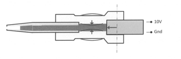
- FIG. 2 is a diagram (part 1) illustrating the operation of the dispensing device 100 according to the present embodiment.
- the voltage applied to the piezoelectric element actuator 50 is zero. Therefore, the rod-shaped member 30 is disposed at the reference position.
- FIG. 3 is a diagram (part 2) illustrating the operation of the dispensing device 100 according to the present embodiment.
- the voltage applied to the piezoelectric element actuator 50 is a positive value. For example, it is 10V.
- the rod-shaped member 30 advances toward the opening 10 b of the glass pipette 10.
- the liquid inside the liquid storage unit constituted by the glass pipette 10 and the tubular elastic member 20 moves to the side of the dispensing port 10a.
- the tubular elastic member 20 has a small internal volume of the tubular elastic member 20.
- the tubular elastic member 20 is a tubular elastic member It elastically deforms so that the internal volume of 20 becomes small.
- the tubular elastic member 20 is axially contracted. That is, the tubular elastic member 20 contracts.
- the cross-sectional area of at least a part of the tubular elastic member 20 may be slightly deformed so as to be smaller. At this time, the cross-sectional area of at least a part of the inside of the tubular elastic member 20 is slightly narrower than the cross-sectional area of the inside of the tubular elastic member 20 in the normal case. That is, the tubular elastic member 20 is slightly recessed. Even in this case, this dispensing apparatus 100 can perform dispensing with sufficiently high accuracy.
- the thickness of the tube of the tubular elastic member 20 When the thickness of the tube of the tubular elastic member 20 is thin, the cross-sectional area of at least a part of the tubular elastic member 20 is deformed so as to be large. In this case, a gap is likely to occur between the inner side surface of the tubular elastic member 20 and the outer side surface of the glass pipette 10. In addition, a gap is likely to be generated between the inner side surface of the tubular elastic member 20 and the outer side surface of the rod-like member 30. In this case, even if the rod-like member 30 is pushed out by the piezoelectric element actuator 50, the liquid escapes into these gaps. Therefore, the applied voltage applied to the piezoelectric element actuator 50 and the discharge amount of the liquid discharged from the dispensing port 10a are not in a proportional relationship. Therefore, it is preferable that the thickness of the tube of the tubular elastic member 20 be sufficiently thick.
- the dispensing device 100 can dispense the amount of liquid substantially in proportion to the voltage applied to the piezoelectric element actuator 50 set by the control unit 60. For example, as described later, a liquid of an amount of about 10 pL can be dispensed with high accuracy.
- the tubular elastic member 20 is elastically deformed in a region where it can be elastically deformed. Then, the tubular elastic member 20 elastically deforms in the axial direction of the tubular shape.
- the dispensing member of the present embodiment is a glass pipette 10.
- the material of the dispensing member may be a resin such as acrylic or other metal.
- the dispensing member may have a tubular shape having a bending portion. Also, the inner diameter of the dispensing member may be smaller toward the dispensing port.
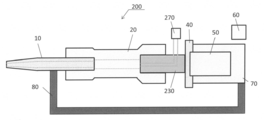
- FIG. 4 is a view showing a schematic configuration of a dispensing device 200 according to a modification of the present embodiment. As shown in FIG. 4, the dispensing device 200 has a rod-like member 230 having a through hole, and a pump 270 for delivering liquid to the through hole.
- Leaf Spring and Piezoelectric Actuator The leaf spring 40 may be omitted as the case may be. In that case, the rod-like member 30 is provided on the piezoelectric element actuator 50. Alternatively, the piezoelectric element actuator 50 itself may play the role of the rod-like member 30.
- the dispensing device 100 of the present embodiment includes the glass pipette 10, the tubular elastic member 20, the rod member 30, the piezoelectric element actuator 50, and the control unit 60. .
- the tubular elastic member 20 deforms in response to the movement of the rod-like member 30. Therefore, the dispensing apparatus 100 can dispense a minute volume of liquid.
- the second embodiment is a method of dispensing a liquid containing cells and the like.
- the dispensing apparatus 100 of the first embodiment is used for explanation. However, dispensing devices other than the dispensing device 100 of the first embodiment can also be used. However, for the dispensing method of the present embodiment, it is preferable to use the dispensing apparatus 100 of the first embodiment.
- the method of dispensing cells includes a first liquid injection step of injecting a first liquid into the inside of the glass pipette 10, a gas injection step of injecting a gas into the inside of the glass pipette 10, and glass A cell collecting step of collecting only one cell in the second liquid while injecting the second liquid into the inside of the pipette 10, and a releasing step of releasing the second liquid and cells from the glass pipette 10 into the inside of the container And.
- First Liquid Injecting Step As shown in FIG. 5, the first liquid is injected into the inside of the glass pipette 10 of the dispensing device 100. This first liquid is not the liquid to be dispensed.
- Gas Injection Step As shown in FIG. 6, after injecting the first liquid, gas is injected into the interior of the glass pipette 10 following the first liquid.
- the gas is, for example, air.
- the first liquid is confined to the back side of the dispensing apparatus 100.
- Second liquid injection step (cell collection step) As shown in FIG. 7, only one cell in the second liquid is collected while injecting the second liquid from the container A10 subsequently to the gas after the injection of the gas. This second liquid is the liquid to be dispensed. At this stage, separation bubbles X1 are generated between the first liquid and the second liquid. And the 2nd liquid inside container A10 contains a plurality of cells, for example. Here, the dispensing apparatus 100 can easily collect only one of the plurality of cells.
- control unit 60 of the dispensing device 100 includes the first liquid located on the side of the tubular elastic member 20, the second liquid located on the side of the dispensing port 10a, the first liquid, and the first liquid.
- the applied voltage is controlled such that a separation bubble located between the two liquids is generated.
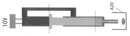
- the second liquid and cells are released from the glass pipette 10 to the inside of the container A 20 outside the dispensing apparatus 100. Thereby, the second liquid and one cell are supplied to the inside of the container A20.
- control unit 60 is configured such that the first liquid located on the side of the tubular elastic member 20, the second liquid located on the side of the dispensing port 10a, and the first liquid and the second liquid.
- the applied voltage is controlled so that the separated air bubbles located at
- the separated air bubble X1 is generated inside the glass pipette 10.
- the separation bubble X1 plays a role of separating the first liquid and the second liquid so that they do not mix.
- the separation bubble X1 also plays a role of shielding to prevent active cells from moving from the second liquid to the first liquid.
- Modification 3-1 Method of Dispensing Liquid
- one of a large number of cells contained in the second liquid is dispensed. However, only the liquid may be dispensed without dispensing the cells.
- the second liquid injection step the second liquid is injected into the interior of the glass pipette 10 following the gas. At this stage, separation bubbles X1 are generated between the first liquid and the second liquid.
- the second liquid is released from the glass pipette 10 to the inside of the container A10 and a part of the separation bubble X1 is released.
- the second liquid can be reliably released. For this reason, the second liquid and cells do not remain inside the glass pipette 10 and the tubular elastic member 20. In addition, there is no possibility that the dispensing apparatus 100 may discharge
- two separation bubbles X1 may be generated inside the glass pipette 10 and the tubular elastic member 20. Therefore, the gas injection process and the liquid injection process are repeated. That is, the gas is injected after the second liquid injection step. Subsequently, only one third liquid and new cells are collected. At this stage, cells are held one by one in the second liquid and the third liquid in a state of being separated by the separation bubble X1. Therefore, two cells can be continuously dispensed by sequentially releasing the third liquid and the second liquid. The same applies to three or more cells.
- Dispensing unit A dispensing unit may be used to carry out this cell dispensing method.
- the dispensing unit includes, for example, the dispensing apparatus 100 according to the first embodiment, a drive unit for moving in the X-axis direction, the Y-axis direction, and the Z-axis direction, and a drive control unit for controlling the drive unit. And a sensor for capturing cells in the liquid.
- the separation bubble X1 suitably separates the first liquid and the second liquid. Therefore, cells contained in the second liquid can not escape to the first liquid. Thus, for example, one cell and one second liquid can be supplied to one well.
- the dispensing device 100 of the first embodiment has a tubular elastic member 20.
- materials other than the tubular elastic member 20 elastically deform as long as they can be elastically deformed.
- glass does not exceed the yield point, and elastically deforms to a small extent if it is an elastically deformable region. Glass is generally not easily deformed. Therefore, it can be used when dispensing a small amount of liquid.
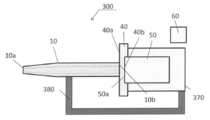
- FIG. 9 is a view showing a schematic configuration of a dispensing device 300 of the present embodiment.
- the dispensing device 300 includes a glass pipette 10, a plate spring 40, a piezoelectric element actuator 50, a control unit 60, a housing 370, and a fixing unit 380.
- the housing 370 is a main body of the dispensing device 300.
- the fixing portion 380 is for fixing a predetermined portion of the glass pipette 10 to the housing 370.
- the glass pipette 10 is a tubular member having a dispensing port 10a and an opening 10b.
- the glass pipette 10 is elastically deformed in the cylindrical shape in the elastically deformable region.
- the glass pipette 10 is an integral glass member having a dispensing port 10a.
- the leaf spring 40 has a first surface 40 a and a second surface 40 b.
- the opening 10 b of the glass pipette 10 is joined to the first surface 40 a of the plate spring 40.
- an adhesive may be used.
- the piezoelectric element actuator 50 presses the glass pipette 10 in the axial direction of the cylindrical shape. Therefore, the distance between the opening 10b and the fixing portion 380 in the glass pipette 10 is slightly reduced. That is, the glass pipette 10 is elastically deformed in the cylindrical shape in the elastically deformable region.
- the amount of compression is approximately proportional to the voltage applied to the piezoelectric element actuator 50 as described later. This compression reduces the volume inside the glass pipette 10. Then, a small amount of liquid is dispensed.
- the glass pipette 10 of the present embodiment is difficult to deform, it elastically deforms in an elastically deformable region. Therefore, the glass pipette 10 is slightly elastically deformed with respect to the input voltage. Therefore, the dispensing apparatus 300 of the present embodiment is suitable for use in dispensing a small amount of liquid.
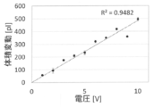
- FIG. 10 is a graph (part 1) showing the relationship between the applied voltage and the discharge amount of the liquid. As shown in FIG. 10, the applied voltage and the discharge amount of the liquid are in a substantially direct proportion relationship. Therefore, if an appropriate applied voltage is input to the piezoelectric element actuator 50, dispensing can be performed with high accuracy.
- the applied voltage and the discharge amount of the liquid are in a substantially direct proportional relationship also with respect to the liquid amount of 1 nL or less. Therefore, for example, dispensing of about 10 pL can be performed with high accuracy.
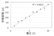
- FIG. 11 is a graph (part 2) showing the relationship between the applied voltage and the discharge amount of the liquid. As shown in FIG. 11, the applied voltage and the discharge amount of the liquid are in a substantially direct proportion relationship. Therefore, if an appropriate applied voltage is input to the piezoelectric element actuator 50, dispensing can be performed with high accuracy.
- the applied voltage and the discharge amount of the liquid are in a substantially direct proportional relationship also with respect to the liquid amount of 1 nL or less. Therefore, for example, dispensing of about 10 pL can be performed with high accuracy.
- the compressed portion (glass pipette 10) of the dispensing device 300 of the third embodiment is less susceptible to elastic deformation than the compressed portion (tubular elastic member 20) of the dispensing device 100 of the first embodiment. Therefore, the amount of liquid dispensed is small for the same input voltage. Therefore, the dispensing apparatus 300 of the third embodiment is suitable for dispensing a smaller amount of liquid.
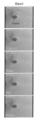
- FIG. 12 is a series of photographs taken from the time when the dispensing apparatus 100 extracts only one bead until it is released.
- the diameter of the beads is about 1 ⁇ m.
- the dispensing apparatus 100 can collect only one bead with high accuracy and with certainty. Moreover, the dispensing apparatus 100 can discharge only one bead.
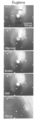
- FIG. 13 is the continuous photograph which image
- the dispensing device in the first aspect has a dispensing port, a tubular member connected to the dispensing port and elastically deformed, and an actuator for compressing the tubular member in the axial direction of the tubular shape.
- the tubular member is elastically deformed in the cylindrical shape in the elastically deformable region.
- the tubular member is an integral glass member having a dispensing port.
- the dispensing device in the third aspect has a dispensing member having a dispensing port and an opening on the opposite side of the dispensing port.
- the tubular member is a tubular elastic member having a first open end and a second open end. The first open end of the tubular elastic member is connected to the opening of the dispensing member.
- the tubular elastic member is elastic so that the internal volume of the tubular elastic member is reduced when the actuator pushes from the second open end side of the tubular elastic member toward the first open end side of the tubular elastic member. Deform.
- the dispensing device in the fourth aspect has a rod-like member connected to the inner wall of the tubular elastic member.
- the actuator reciprocates the rod-like member in the axial direction of the tubular elastic member.
- the side of the first open end of the tubular elastic member covers the side of the opening of the dispensing member.
- the side of the second open end of the tubular elastic member covers at least the tip portion of the rod-like member.
- the tubular elastic member is elastic such that the cross-sectional area inside the tubular elastic member becomes smaller when the actuator pushes the rod-like member toward the opening of the dispensing member. Deform.
- the rod-like member is in non-contact with the dispensing member over the reciprocating motion of the actuator.
- the outer diameter on the opening side of the dispensing member is larger than the inner diameter of the tubular elastic member.
- the outer diameter of the tip portion of the rod-shaped member is larger than the inner diameter of the tubular elastic member.
- the dispensing device in the eighth aspect has a control unit that controls an applied voltage to be applied to the actuator.
- the actuator is a piezoelectric actuator.
- control unit includes a first liquid located on the side of the tubular member, a second liquid located on the side of the dispensing port, a first liquid, and a second fluid.
- the applied voltage is controlled so that a separation bubble located between the liquid and the liquid is generated.
- the dispensing device in the tenth aspect has a leaf spring.
- a leaf spring is disposed between the actuator and the tubular member.
- the liquid dispensing method includes a first liquid injecting step of injecting a first liquid into the inside of the dispensing member, and a gas is injected into the inside of the dispensing member following the first liquid.
- a gas injection step a second liquid injection step of injecting a second liquid into the interior of the dispensing member following the gas, a part of the gas while discharging the second liquid from the dispensing member into the interior of the container
- the dispensing method of cells in the twelfth aspect comprises a first liquid injecting step of injecting a first liquid into the inside of the dispensing member, and a gas is injected into the inside of the dispensing member following the first liquid.
- a gas injection step a cell collection step of collecting the cells in the second liquid one by one while injecting a second liquid into the interior of the dispensing member following the gas, a second liquid from the dispensing member, and Releasing the cells into the interior of the container.
- DESCRIPTION OF SYMBOLS 100 ... Dispensing apparatus 10 ... Glass pipette 10a ... Dispensing port 10b ... Opening part 20 ... Tubular elastic member 20a ... 1st opening end 20b ... 2nd opening end 30 ... Rod member 40 ... Flat spring 50 . Piezoelectric element actuator 60 ... control unit
Landscapes
- Health & Medical Sciences (AREA)
- Chemical & Material Sciences (AREA)
- Life Sciences & Earth Sciences (AREA)
- Engineering & Computer Science (AREA)
- Organic Chemistry (AREA)
- Wood Science & Technology (AREA)
- Bioinformatics & Cheminformatics (AREA)
- Zoology (AREA)
- Chemical Kinetics & Catalysis (AREA)
- Clinical Laboratory Science (AREA)
- General Health & Medical Sciences (AREA)
- Biochemistry (AREA)
- Molecular Biology (AREA)
- Sustainable Development (AREA)
- Microbiology (AREA)
- Biotechnology (AREA)
- General Engineering & Computer Science (AREA)
- Biomedical Technology (AREA)
- Genetics & Genomics (AREA)
- Human Computer Interaction (AREA)
- Analytical Chemistry (AREA)
- Physics & Mathematics (AREA)
- General Physics & Mathematics (AREA)
- Immunology (AREA)
- Pathology (AREA)
- Sampling And Sample Adjustment (AREA)
- Apparatus Associated With Microorganisms And Enzymes (AREA)
- Micro-Organisms Or Cultivation Processes Thereof (AREA)
- Devices For Use In Laboratory Experiments (AREA)
- Feeding, Discharge, Calcimining, Fusing, And Gas-Generation Devices (AREA)
Abstract
この技術の目的は、非常に高い精度で液体を分注することのできる分注装置および液体の分注方法および細胞の分注方法を提供することである。分注装置(100)は、ガラスピペット(10)と、管状弾性部材(20)と、棒状部材(30)と、圧電素子アクチュエーター(50)と、を有する。管状弾性部材(20)の第1の開口端(20a)の側は、ガラスピペット(10)の開口部(10b)の側を覆っている。管状弾性部材(20)の第2の開口端(20b)の側は、棒状部材(30)の少なくとも先端部分を覆っている。管状弾性部材(20)は、圧電素子アクチュエーター(50)が棒状部材(30)をガラスピペット(10)の開口部(10b)に向けて押し出している場合に、管状弾性部材(20)の内部の体積が小さくなるように変形する。
Description
本明細書の技術分野は、分注装置および液体の分注方法および細胞の分注方法に関する。
分注装置は試料もしくは試薬をウェルに供給するために用いられる。高精度な測定を実施するために、分注装置は、高精度に液体を分注できることが好ましい。そのため、高精度に分注可能な分注装置が開発されてきている。
例えば、特許文献1には、ピペットと、ピストンと、圧電アクチュエーターと、を有する分注装置が開示されている。この分注装置は、液滴を容器の底に直接飛翔させることができる。そのためこの分注装置では、チップタッチ操作およびチップダウン操作を実施する必要性がない。また、この分注装置は、1μL程度の分注を実施することができる。
ところで、細胞等について実験を実施する場合には、各細胞を各ウェルに1個ずつ分注することがある。細胞を1個ずつ分注する場合には、1nL以下の液体を分注することが要求される。細胞の種類によるものの、例えば、10pLの液体を分注する。そのためには、分注装置に非常に高い精度が要求される。
また、実際に、細胞を1個ずつ分注することは非常に困難である。従来においては、分注装置が、多数の細胞を含む培養液中から1個の細胞を取り出すことに成功するまで採取と放出とを何回も繰り返す必要があった。このような状況では、実験する際に細胞を1個ずつウェルに供給するために、膨大な時間が必要となる。
本明細書の技術は、前述した従来の技術が有する問題点を解決するためになされたものである。すなわちその課題とするところは、非常に高い精度で液体を分注することのできる分注装置および液体の分注方法および細胞の分注方法を提供することである。
第1の態様における分注装置は、分注口と、分注口に連なるとともに弾性変形する管状部材と、管状部材を筒形状の軸方向に圧縮するためのアクチュエーターと、を有する。管状部材は、弾性変形可能な領域で筒形状の軸方向に弾性変形する。
この分注装置においては、管状部材は、弾性変形可能な領域で筒形状の軸方向に弾性変形する。つまり、管状部材は、アクチュエーターの変位量に応じて変形する。この圧縮により、管状部材の内部の体積は減少する。したがって、アクチュエーターへの印加電圧と放出する液体量との間にほぼ正比例関係が成り立つ。ゆえに、非常に高い精度で液体を分注する分注装置が実現されている。また、この分注装置は、培養液中の1個の細胞をウェルに確実に分配することが可能である。
本明細書では、非常に高い精度で液体を分注することのできる分注装置および液体の分注方法および細胞の分注方法が提供されている。
以下、具体的な実施形態について、分注装置および液体の分注方法および細胞の分注方法を例に挙げて図を参照しつつ説明する。
(第1の実施形態)
1.分注装置
図1は、本実施形態の分注装置100の概略構成を示す図である。図1に示すように、分注装置100は、ガラスピペット10と、管状弾性部材20と、棒状部材30と、板バネ40と、圧電素子アクチュエーター50と、制御部60と、筐体70と、固定部80と、を有する。
1.分注装置
図1は、本実施形態の分注装置100の概略構成を示す図である。図1に示すように、分注装置100は、ガラスピペット10と、管状弾性部材20と、棒状部材30と、板バネ40と、圧電素子アクチュエーター50と、制御部60と、筐体70と、固定部80と、を有する。
ガラスピペット10は、分注する液体を収容するための分注部材である。ガラスピペット10は、分注装置100の本体に固定されている。ガラスピペット10は、円筒形状を有する。ガラスピペット10は、分注口10aと開口部10bとを有する。分注口10aは、液体をガラスピペット10に注入したりガラスピペット10から放出したりするための開口部である。開口部10bは、分注口10aの反対側に位置する開口部である。開口部10bは、管状弾性部材20に嵌められている。具体的には、ガラスピペット10の開口部10bは、管状弾性部材20の第1の開口端20aの側で覆われている。ガラスピペット10の材質はもちろんガラスである。
管状弾性部材20は、円筒形状の弾性部材である。管状弾性部材20は、分注口10aに連なるとともに弾性変形する管状部材である。管状弾性部材20は、ガラスピペット10と棒状部材30とを接続するための接続部材である。そのため、管状弾性部材20は、ガラスピペット10および棒状部材30に接続されている。管状弾性部材20は、第1の開口端20aと第2の開口端20bとを有する。管状弾性部材20の第1の開口端20aの側は、ガラスピペット10の開口部10bの側を覆っている。管状弾性部材20の第2の開口端20bの側は、棒状部材30の少なくとも先端部分を覆っている。つまり、管状弾性部材20の第2の開口端20bの内部には、棒状部材30の第1の端部30aが嵌められている。管状弾性部材20の材質は樹脂である。例えば、シリコーン樹脂が挙げられる。
棒状部材30は、管状弾性部材20の内壁に接続されている。具体的には、棒状部材30は、管状弾性部材20に挿入されている。棒状部材30は、第1の端部30aと第2の端部30bとを有する。第1の端部30aは、棒状部材30の先端部分である。第2の端部30bは、第1の端部30aの反対側の端部である。棒状部材30は、管状弾性部材20の軸方向に移動する。棒状部材30の第1の端部30aは、管状弾性部材20の第2の開口端20bの側から挿入されている。第2の端部30bは、板バネ40に固定されている。ここで、ガラスピペット10の内部の空間と管状弾性部材20の内部の空間と棒状部材30の第1の端部とは、空洞部を形成する。この空洞部は、液体等を収容することができるようになっている。棒状部材30の材質は、金属である。また、硬度の高い樹脂等、その他の固体であってもよい。
板バネ40は、圧電素子アクチュエーター50と棒状部材30との間の位置に配置されている。また、板バネ40は、圧電素子アクチュエーター50と管状弾性部材20との間の位置に配置されている。板バネ40は、第1面40aと第2面40bとを有する。第1面40aは、棒状部材30の第2の端部30bに接触している。第2面40bは、圧電素子アクチュエーター50の第1面50aに接触している。
圧電素子アクチュエーター50は、棒状部材30を管状弾性部材20の軸方向に往復させるためのアクチュエーターである。圧電素子アクチュエーター50は、管状弾性部材20を筒形状の軸方向に圧縮する。また、圧電素子アクチュエーター50は、棒状部材30を棒状部材30の軸方向に往復させる。圧電素子アクチュエーター50は、第1の端部50aを有する。圧電素子アクチュエーター50の第1の端部50aは、板バネ40の第2面40bに接触している。
制御部60は、圧電素子アクチュエーター50に印加する印加電圧を制御するためのものである。例えば、制御部60は、圧電素子アクチュエーター50に正の電圧を印加する。この場合に、圧電素子アクチュエーター50は、棒状部材30をガラスピペット10の側に押し出す。また、制御部60は、圧電素子アクチュエーター50に負の電圧を印加する。この場合に、圧電素子アクチュエーター50は、棒状部材30をガラスピペット10の反対側に引く。これにより、圧電素子アクチュエーター50は、ガラスピペット10の軸方向に往復運動する。それに伴って、棒状部材30は、ガラスピペット10の軸方向に往復運動する。
筐体70は、分注装置100の本体である。固定部80は、ガラスピペット10の所定の箇所を筐体70に固定するためのものである。
2.各部のサイズ
ガラスピペット10の開口部10b側の外径は、管状弾性部材20の内径よりも大きい。そのため、管状弾性部材20の第1の開口端20aの側は、ガラスピペット10を覆うように変形している。つまり、管状弾性部材20の内壁は押し広げられている。棒状部材30の第1の端部30aの外径は、管状弾性部材20の内径よりも大きい。そのため、管状弾性部材20の第2の開口端20bの側は、棒状部材30を覆うように変形している。つまり、管状弾性部材20の内壁は押し広げられている。
ガラスピペット10の開口部10b側の外径は、管状弾性部材20の内径よりも大きい。そのため、管状弾性部材20の第1の開口端20aの側は、ガラスピペット10を覆うように変形している。つまり、管状弾性部材20の内壁は押し広げられている。棒状部材30の第1の端部30aの外径は、管状弾性部材20の内径よりも大きい。そのため、管状弾性部材20の第2の開口端20bの側は、棒状部材30を覆うように変形している。つまり、管状弾性部材20の内壁は押し広げられている。
棒状部材30が管状弾性部材20に向かって押し出される場合には、棒状部材30は、管状弾性部材20を押し縮める。この応力により、管状弾性部材20は、後述するように変形する。その際に、ガラスピペット10および棒状部材30は、管状弾性部材20の内壁に対して摺動しない。棒状部材30の外径は、ガラスピペット10の内径よりも大きい。棒状部材30は、圧電素子アクチュエーター50の往復運動にわたってガラスピペット10と非接触である。そのため、棒状部材30とガラスピペット10とが干渉するおそれはない。
ガラスピペット10における円筒形状の外径は0.8mm以上1.2mm以下である。管状弾性部材20の円筒形状の内径は0.6mm以上1.0mm以下である。棒状部材30の円筒形状の外径は1.2mm以上2.0mm以下である。これらは、おおよその値であり、上記以外の数値範囲であってもよい。
3.管状弾性部材の動作
図2は、本実施形態の分注装置100の動作を示す図(その1)である。圧電素子アクチュエーター50に印加する電圧はゼロである。そのため、棒状部材30は基準位置に配置されている。
図2は、本実施形態の分注装置100の動作を示す図(その1)である。圧電素子アクチュエーター50に印加する電圧はゼロである。そのため、棒状部材30は基準位置に配置されている。
図3は、本実施形態の分注装置100の動作を示す図(その2)である。圧電素子アクチュエーター50に印加する電圧は正の値である。例えば、10Vである。この場合には、棒状部材30は、ガラスピペット10の開口部10bに向かって進行する。これにより、ガラスピペット10および管状弾性部材20で構成される液体収容部の内部の液体は、分注口10aの側に移動する。
図3に示すように、圧電素子アクチュエーター50が棒状部材30をガラスピペット10の開口部10bに向けて押し出している場合に、管状弾性部材20は、管状弾性部材20の内部の体積が小さくなるように弾性変形する。つまり、圧電素子アクチュエーター50が管状弾性部材20の第2の開口端20b側から管状弾性部材20の第1の開口端20a側に向けて押し出している場合に、管状弾性部材20は、管状弾性部材20の内部の体積が小さくなるように弾性変形する。このとき管状弾性部材20は、軸方向に縮んでいる。つまり、管状弾性部材20は収縮する。
4.本実施形態の効果
管状弾性部材20が変形した場合に、管状弾性部材20の内側面とガラスピペット10の外側面との間に隙間が生じない。同様に、管状弾性部材20の内側面と棒状部材30の外側面との間に隙間が生じない。したがって、圧電素子アクチュエーター50に印加する印加電圧と分注口10aから排出される液体の排出量とはほぼ比例する。つまり、この分注装置100は高精度な分注を実施することができる。
管状弾性部材20が変形した場合に、管状弾性部材20の内側面とガラスピペット10の外側面との間に隙間が生じない。同様に、管状弾性部材20の内側面と棒状部材30の外側面との間に隙間が生じない。したがって、圧電素子アクチュエーター50に印加する印加電圧と分注口10aから排出される液体の排出量とはほぼ比例する。つまり、この分注装置100は高精度な分注を実施することができる。
また、変形の程度によっては、管状弾性部材20の少なくとも一部の内部の断面積が小さくなるようにわずかに変形する。このとき、管状弾性部材20の内側における少なくとも一部の断面積は、通常の場合における管状弾性部材20の内側の断面積よりもわずかに狭い。つまり、管状弾性部材20は、わずかに凹んでいる。この場合であっても、この分注装置100は十分に高精度な分注を実施することができる。
なお、管状弾性部材20の筒の厚みが薄いと、管状弾性部材20の少なくとも一部の内部の断面積が大きくなるように変形する。この場合には、管状弾性部材20の内側面とガラスピペット10の外側面との間に隙間が生じやすい。また、管状弾性部材20の内側面と棒状部材30の外側面との間に隙間が生じやすい。この場合には、棒状部材30が圧電素子アクチュエーター50に押し出されても、液体がこれらの隙間に逃げてしまう。したがって、圧電素子アクチュエーター50に印加する印加電圧と分注口10aから排出される液体の排出量とは比例関係にない。よって、管状弾性部材20の筒の厚みは、十分に厚いことが好ましい。
このように、この分注装置100は、制御部60が設定する圧電素子アクチュエーター50の印加電圧にほぼ比例する量の液体を分注することができる。例えば、後述するように10pL程度の量の液体を高精度で分注することができる。
この分注装置100においては、管状弾性部材20が弾性変形可能な領域で弾性変形する。そして、管状弾性部材20は、筒形状の軸方向に弾性変形する。
5.変形例
5-1.分注部材
本実施形態の分注部材は、ガラスピペット10である。しかし、分注部材の材質は、ガラスの他にアクリル等の樹脂やその他の金属であってもよい。また、分注部材は、屈曲部を有する筒形状であってもよい。また、分注部材の内径は、分注口に向かうにつれて小さくなっていてもよい。
5-1.分注部材
本実施形態の分注部材は、ガラスピペット10である。しかし、分注部材の材質は、ガラスの他にアクリル等の樹脂やその他の金属であってもよい。また、分注部材は、屈曲部を有する筒形状であってもよい。また、分注部材の内径は、分注口に向かうにつれて小さくなっていてもよい。
5-2.ポンプ
図4は、本実施形態の変形例における分注装置200の概略構成を示す図である。図4に示すように、分注装置200は、貫通孔を有する棒状部材230と、その貫通孔に液体を送出するポンプ270と、を有する。
図4は、本実施形態の変形例における分注装置200の概略構成を示す図である。図4に示すように、分注装置200は、貫通孔を有する棒状部材230と、その貫通孔に液体を送出するポンプ270と、を有する。
5-3.板バネおよび圧電素子アクチュエーター
板バネ40については場合によって省略してもよい。その場合には、圧電素子アクチュエーター50の上に棒状部材30が設けられている。もしくは、圧電素子アクチュエーター50自身が、棒状部材30の役割を担ってもよい。
板バネ40については場合によって省略してもよい。その場合には、圧電素子アクチュエーター50の上に棒状部材30が設けられている。もしくは、圧電素子アクチュエーター50自身が、棒状部材30の役割を担ってもよい。
5-4.組み合わせ
上記の変形例を自由に組み合わせてもよい。
上記の変形例を自由に組み合わせてもよい。
6.本実施形態のまとめ
以上説明したように、本実施形態の分注装置100は、ガラスピペット10と、管状弾性部材20と、棒状部材30と、圧電素子アクチュエーター50と、制御部60と、を有する。管状弾性部材20が、棒状部材30の動作に応じて変形する。そのため、分注装置100は、微小体積の液体を分注することができる。
以上説明したように、本実施形態の分注装置100は、ガラスピペット10と、管状弾性部材20と、棒状部材30と、圧電素子アクチュエーター50と、制御部60と、を有する。管状弾性部材20が、棒状部材30の動作に応じて変形する。そのため、分注装置100は、微小体積の液体を分注することができる。
(第2の実施形態)
第2の実施形態について説明する。第2の実施形態は、細胞等を含む液体の分注方法である。説明のために、第1の実施形態の分注装置100を用いる。しかし、第1の実施形態の分注装置100以外の分注装置を用いることもできる。ただし、本実施形態の分注方法は、第1の実施形態の分注装置100を用いることが好適である。
第2の実施形態について説明する。第2の実施形態は、細胞等を含む液体の分注方法である。説明のために、第1の実施形態の分注装置100を用いる。しかし、第1の実施形態の分注装置100以外の分注装置を用いることもできる。ただし、本実施形態の分注方法は、第1の実施形態の分注装置100を用いることが好適である。
1.細胞の分注方法
この細胞の分注方法は、ガラスピペット10の内部に第1の液体を注入する第1の液体注入工程と、ガラスピペット10の内部に気体を注入する気体注入工程と、ガラスピペット10の内部に第2の液体を注入しつつ第2の液体中の細胞を1個だけ採取する細胞採取工程と、ガラスピペット10から第2の液体および細胞を容器の内部に放出する放出工程と、を有する。
この細胞の分注方法は、ガラスピペット10の内部に第1の液体を注入する第1の液体注入工程と、ガラスピペット10の内部に気体を注入する気体注入工程と、ガラスピペット10の内部に第2の液体を注入しつつ第2の液体中の細胞を1個だけ採取する細胞採取工程と、ガラスピペット10から第2の液体および細胞を容器の内部に放出する放出工程と、を有する。
1-1.第1の液体注入工程
図5に示すように、分注装置100のガラスピペット10の内部に第1の液体を注入する。この第1の液体は、分注される液体ではない。
図5に示すように、分注装置100のガラスピペット10の内部に第1の液体を注入する。この第1の液体は、分注される液体ではない。
1-2.気体注入工程
図6に示すように、第1の液体を注入後に第1の液体に続いてガラスピペット10の内部に気体を注入する。気体は、例えば空気である。これにより、第1の液体は、分注装置100の奥側に閉じ込められる。
図6に示すように、第1の液体を注入後に第1の液体に続いてガラスピペット10の内部に気体を注入する。気体は、例えば空気である。これにより、第1の液体は、分注装置100の奥側に閉じ込められる。
1-3.第2の液体注入工程(細胞採取工程)
図7に示すように、気体の注入後に気体に続いて容器A10から第2の液体を注入しつつ第2の液体中の細胞を1個だけ採取する。この第2の液体は、分注される液体である。この段階では、第1の液体と第2の液体との間には分離気泡X1が発生している。そして、容器A10の内部の第2の液体は、例えば、複数の細胞を含有している。ここで、分注装置100は、複数の細胞のうち一つの細胞のみを容易に採取することができる。
図7に示すように、気体の注入後に気体に続いて容器A10から第2の液体を注入しつつ第2の液体中の細胞を1個だけ採取する。この第2の液体は、分注される液体である。この段階では、第1の液体と第2の液体との間には分離気泡X1が発生している。そして、容器A10の内部の第2の液体は、例えば、複数の細胞を含有している。ここで、分注装置100は、複数の細胞のうち一つの細胞のみを容易に採取することができる。
このように、分注装置100の制御部60は、管状弾性部材20の側に位置する第1の液体と、分注口10aの側に位置する第2の液体と、第1の液体と第2の液体との間に位置する分離気泡と、が生じるように印加電圧を制御する。
1-4.放出工程
図8に示すように、ガラスピペット10から第2の液体および細胞を分注装置100の外部の容器A20の内部に放出する。これにより、容器A20の内部に第2の液体および1つの細胞が供給される。
図8に示すように、ガラスピペット10から第2の液体および細胞を分注装置100の外部の容器A20の内部に放出する。これにより、容器A20の内部に第2の液体および1つの細胞が供給される。
このように制御部60は、管状弾性部材20の側に位置する第1の液体と、分注口10aの側に位置する第2の液体と、第1の液体と第2の液体との間に位置する分離気泡と、が生じるように印加電圧を制御する。
2.本実施形態の効果
本実施形態では、ガラスピペット10の内部に分離気泡X1を発生させる。分離気泡X1は、第1の液体と第2の液体とが混合しないように分離する役割を担っている。また、分離気泡X1は、活動する細胞が第2の液体中から第1の液体に移動しないようにする遮蔽の役割をも担っている。
本実施形態では、ガラスピペット10の内部に分離気泡X1を発生させる。分離気泡X1は、第1の液体と第2の液体とが混合しないように分離する役割を担っている。また、分離気泡X1は、活動する細胞が第2の液体中から第1の液体に移動しないようにする遮蔽の役割をも担っている。
3.変形例
3-1.液体の分注方法
本実施形態では、第2の液体中に含まれる多数の細胞のうちの1個の細胞を分注する。しかし、細胞を分注せずに、液体のみを分注してもよい。その場合には、第2の液体注入工程では、気体に続いてガラスピペット10の内部に第2の液体を注入する。この段階では、第1の液体と第2の液体との間には分離気泡X1が発生している。放出工程では、ガラスピペット10から第2の液体を容器A10の内部に放出するとともに分離気泡X1の一部を放出する。
3-1.液体の分注方法
本実施形態では、第2の液体中に含まれる多数の細胞のうちの1個の細胞を分注する。しかし、細胞を分注せずに、液体のみを分注してもよい。その場合には、第2の液体注入工程では、気体に続いてガラスピペット10の内部に第2の液体を注入する。この段階では、第1の液体と第2の液体との間には分離気泡X1が発生している。放出工程では、ガラスピペット10から第2の液体を容器A10の内部に放出するとともに分離気泡X1の一部を放出する。
このように分離気泡X1の一部を放出することにより、第2の液体を確実に放出しきることができる。このため第2の液体および細胞がガラスピペット10および管状弾性部材20の内部に残留しない。なお、分注装置100は、第1の液体を容器A10の内部に放出するおそれもない。
3-2.複数の分離気泡
ここで、ガラスピペット10および管状弾性部材20の内部に2個の分離気泡X1を発生させてもよい。そのため、気体注入工程および液体注入工程を繰り返す。つまり、第2の液体注入工程の後に気体を注入する。続いて第3の液体および新たな細胞を1個だけ採取する。この段階で、分離気泡X1により分離された状態で、第2の液体および第3の液体中に1個ずつ細胞が保持されている。そのため、第3の液体および第2の液体を順次放出することにより、2個の細胞を連続的に分注することができる。また、3個以上の細胞についても同様に適用することができる。
ここで、ガラスピペット10および管状弾性部材20の内部に2個の分離気泡X1を発生させてもよい。そのため、気体注入工程および液体注入工程を繰り返す。つまり、第2の液体注入工程の後に気体を注入する。続いて第3の液体および新たな細胞を1個だけ採取する。この段階で、分離気泡X1により分離された状態で、第2の液体および第3の液体中に1個ずつ細胞が保持されている。そのため、第3の液体および第2の液体を順次放出することにより、2個の細胞を連続的に分注することができる。また、3個以上の細胞についても同様に適用することができる。
3-3.分注ユニット
この細胞の分注方法を実施するために分注ユニットを用いてもよい。この分注ユニットは、例えば、第1の実施形態の分注装置100と、X軸方向、Y軸方向、Z軸方向に移動させる駆動部と、駆動部を制御する駆動制御部と、第2の液体中の細胞を捕捉するセンサーと、を有する。
この細胞の分注方法を実施するために分注ユニットを用いてもよい。この分注ユニットは、例えば、第1の実施形態の分注装置100と、X軸方向、Y軸方向、Z軸方向に移動させる駆動部と、駆動部を制御する駆動制御部と、第2の液体中の細胞を捕捉するセンサーと、を有する。
3-4.組み合わせ
上記の変形例を自由に組み合わせてもよい。
上記の変形例を自由に組み合わせてもよい。
4.本実施形態のまとめ
本実施形態では、分離気泡X1が第1の液体と第2の液体とを好適に分離している。そのため、第2の液体に含まれる細胞が第1の液体に逃げることができない。よって、例えば、1個のウェルに1個ずつの細胞および第2の液体を供給することができる。
本実施形態では、分離気泡X1が第1の液体と第2の液体とを好適に分離している。そのため、第2の液体に含まれる細胞が第1の液体に逃げることができない。よって、例えば、1個のウェルに1個ずつの細胞および第2の液体を供給することができる。
(第3の実施形態)
第3の実施形態について説明する。第1の実施形態の分注装置100は、管状弾性部材20を有する。しかし、管状弾性部材20以外の材料であっても弾性変形可能な領域であれば弾性変形する。例えば、ガラスは、降伏点を越えず、弾性変形可能な領域であれば、わずかではあるものの弾性変形する。ガラスは一般に容易には変形しにくい。そのため、少量の液体を分注する場合に用いることができる。
第3の実施形態について説明する。第1の実施形態の分注装置100は、管状弾性部材20を有する。しかし、管状弾性部材20以外の材料であっても弾性変形可能な領域であれば弾性変形する。例えば、ガラスは、降伏点を越えず、弾性変形可能な領域であれば、わずかではあるものの弾性変形する。ガラスは一般に容易には変形しにくい。そのため、少量の液体を分注する場合に用いることができる。
1.分注装置
図9は、本実施形態の分注装置300の概略構成を示す図である。図1に示すように、分注装置300は、ガラスピペット10と、板バネ40と、圧電素子アクチュエーター50と、制御部60と、筐体370と、固定部380と、を有する。
図9は、本実施形態の分注装置300の概略構成を示す図である。図1に示すように、分注装置300は、ガラスピペット10と、板バネ40と、圧電素子アクチュエーター50と、制御部60と、筐体370と、固定部380と、を有する。
筐体370は、分注装置300の本体である。固定部380は、ガラスピペット10の所定の箇所を筐体370に固定するためのものである。
ガラスピペット10は、分注口10aと開口部10bとを有する管状部材である。ガラスピペット10は、弾性変形可能な領域で筒形状の軸方向に弾性変形する。ガラスピペット10は、分注口10aを有する一体のガラス部材である。板バネ40は、第1面40aと第2面40bとを有する。ガラスピペット10の開口部10bは、板バネ40の第1面40aと接合されている。そのために例えば、接着剤等を用いればよい。
2.分注装置の動作
圧電素子アクチュエーター50に所定の電圧を印加することにより、圧電素子アクチュエーター50がガラスピペット10を筒形状の軸方向に押圧する。そのため、ガラスピペット10における開口部10bと固定部380との間の距離がわずかに縮む。つまり、ガラスピペット10は、弾性変形可能な領域で筒形状の軸方向に弾性変形する。この圧縮量は、後述するように、圧電素子アクチュエーター50の印加電圧にほぼ比例する。この圧縮により、ガラスピペット10の内部の体積は縮小する。そして、少量の液体が分注される。
圧電素子アクチュエーター50に所定の電圧を印加することにより、圧電素子アクチュエーター50がガラスピペット10を筒形状の軸方向に押圧する。そのため、ガラスピペット10における開口部10bと固定部380との間の距離がわずかに縮む。つまり、ガラスピペット10は、弾性変形可能な領域で筒形状の軸方向に弾性変形する。この圧縮量は、後述するように、圧電素子アクチュエーター50の印加電圧にほぼ比例する。この圧縮により、ガラスピペット10の内部の体積は縮小する。そして、少量の液体が分注される。
3.本実施形態の効果
本実施形態のガラスピペット10は、変形しにくいものの、弾性変形可能な領域で弾性変形する。そのため、ガラスピペット10は、入力電圧に対してわずかに弾性変形する。したがって、本実施形態の分注装置300は、少量の液体を分注する用途に好適である。
本実施形態のガラスピペット10は、変形しにくいものの、弾性変形可能な領域で弾性変形する。そのため、ガラスピペット10は、入力電圧に対してわずかに弾性変形する。したがって、本実施形態の分注装置300は、少量の液体を分注する用途に好適である。
(実験)
1.印加電圧と液体の排出量との間の関係
第1の実施形態の分注装置100を用いて圧電素子アクチュエーター50に印加する印加電圧と分注口10aから排出される液体の排出量との間の関係を調べた。
1.印加電圧と液体の排出量との間の関係
第1の実施形態の分注装置100を用いて圧電素子アクチュエーター50に印加する印加電圧と分注口10aから排出される液体の排出量との間の関係を調べた。
図10は、印加電圧と液体の排出量との間の関係を示すグラフ(その1)である。図10に示すように、印加電圧と液体の排出量とはほぼ正比例の関係にある。そのため、適切な印加電圧を圧電素子アクチュエーター50に入力すれば、高い精度で分注を実施できる。
また、図10に示すように、1nL以下の液体量に対しても、印加電圧と液体の排出量とはほぼ正比例の関係にある。そのため、例えば、10pL程度の分注についても高い精度で実施することができる。
次に、第3の実施形態の分注装置300を用いて圧電素子アクチュエーター50に印加する電圧と分注口10aから排出される液体の排出量との間の関係を調べた。
図11は、印加電圧と液体の排出量との間の関係を示すグラフ(その2)である。図11に示すように、印加電圧と液体の排出量とはほぼ正比例の関係にある。そのため、適切な印加電圧を圧電素子アクチュエーター50に入力すれば、高い精度で分注を実施できる。
また、図11に示すように、1nL以下の液体量に対しても、印加電圧と液体の排出量とはほぼ正比例の関係にある。そのため、例えば、10pL程度の分注についても高い精度で実施することができる。
なお、第3の実施形態の分注装置300の圧縮部分(ガラスピペット10)は、第1の実施形態の分注装置100の圧縮部分(管状弾性部材20)よりも弾性変形しにくい。そのため、同じ入力電圧に対して、液体の分注量が少ない。したがって、第3の実施形態の分注装置300は、より少量の液体を分注することに適している。
2.細胞等の分注
次に、第1の実施形態の分注装置100の操作性について実験を行った。図12は、分注装置100がビーズを1個だけ採取してから放出するまでを撮影した連続写真である。ビーズの直径は1μm程度である。図12に示すように、分注装置100は、高精度で確実にビーズを1個だけ採取することができる。また、分注装置100は、ビーズを1個だけ放出することができる。
次に、第1の実施形態の分注装置100の操作性について実験を行った。図12は、分注装置100がビーズを1個だけ採取してから放出するまでを撮影した連続写真である。ビーズの直径は1μm程度である。図12に示すように、分注装置100は、高精度で確実にビーズを1個だけ採取することができる。また、分注装置100は、ビーズを1個だけ放出することができる。
図13は、第1の実施形態の分注装置100がユーグレナを1個だけ採取する様子を撮影した連続写真である。図13に示すように、分注装置100は、実際にユーグレナを1個だけ採取することができる。したがって、変形例3-3において説明する分注ユニットを用いることにより、溶液中の細胞を1個ずつウェルに分注することができる。
A.付記
第1の態様における分注装置は、分注口と、分注口に連なるとともに弾性変形する管状部材と、管状部材を筒形状の軸方向に圧縮するためのアクチュエーターと、を有する。管状部材は、弾性変形可能な領域で筒形状の軸方向に弾性変形する。
第1の態様における分注装置は、分注口と、分注口に連なるとともに弾性変形する管状部材と、管状部材を筒形状の軸方向に圧縮するためのアクチュエーターと、を有する。管状部材は、弾性変形可能な領域で筒形状の軸方向に弾性変形する。
第2の態様における分注装置においては、管状部材は、分注口を有する一体のガラス部材である。
第3の態様における分注装置は、分注口と分注口の反対側に開口部とを有する分注部材を有する。管状部材は、第1の開口端および第2の開口端を有する管状弾性部材である。管状弾性部材の第1の開口端は、分注部材の開口部と接続されている。管状弾性部材は、アクチュエーターが管状弾性部材の第2の開口端側から管状弾性部材の第1の開口端側に向けて押し出している場合に、管状弾性部材の内部の体積が小さくなるように弾性変形する。
第4の態様における分注装置は、管状弾性部材の内壁に接続されている棒状部材を有する。アクチュエーターは、棒状部材を管状弾性部材の軸方向に往復させるものである。管状弾性部材の第1の開口端の側は、分注部材の開口部の側を覆っている。管状弾性部材の第2の開口端の側は、棒状部材の少なくとも先端部分を覆っている。
第5の態様における分注装置においては、管状弾性部材は、アクチュエーターが棒状部材を分注部材の開口部に向けて押し出している場合に、管状弾性部材の内部の断面積が小さくなるように弾性変形する。
第6の態様における分注装置においては、棒状部材は、アクチュエーターの往復運動にわたって分注部材と非接触である。
第7の態様における分注装置においては、分注部材の開口部側の外径が、管状弾性部材の内径よりも大きい。棒状部材の先端部分の外径が、管状弾性部材の内径よりも大きい。
第8の態様における分注装置は、アクチュエーターに印加する印加電圧を制御する制御部を有する。アクチュエーターは圧電素子アクチュエーターである。
第9の態様における分注装置においては、制御部は、管状部材の側に位置する第1の液体と、分注口の側に位置する第2の液体と、第1の液体と第2の液体との間に位置する分離気泡と、が生じるように印加電圧を制御する。
第10の態様における分注装置は、板バネを有する。板バネは、アクチュエーターと管状部材との間に配置されている。
第11の態様における液体の分注方法は、分注部材の内部に第1の液体を注入する第1の液体注入工程と、第1の液体に続いて分注部材の内部に気体を注入する気体注入工程と、気体に続いて分注部材の内部に第2の液体を注入する第2の液体注入工程と、分注部材から第2の液体を容器の内部に放出するとともに気体の一部を放出する放出工程と、を有する。
第12の態様における細胞の分注方法は、分注部材の内部に第1の液体を注入する第1の液体注入工程と、第1の液体に続いて分注部材の内部に気体を注入する気体注入工程と、気体に続いて分注部材の内部に第2の液体を注入しつつ第2の液体中の細胞を1個ずつ採取する細胞採取工程と、分注部材から第2の液体および細胞を容器の内部に放出する放出工程と、を有する。
100…分注装置
10…ガラスピペット
10a…分注口
10b…開口部
20…管状弾性部材
20a…第1の開口端
20b…第2の開口端
30…棒状部材
40…板バネ
50…圧電素子アクチュエーター
60…制御部
10…ガラスピペット
10a…分注口
10b…開口部
20…管状弾性部材
20a…第1の開口端
20b…第2の開口端
30…棒状部材
40…板バネ
50…圧電素子アクチュエーター
60…制御部
Claims (12)
- 分注口と、
前記分注口に連なるとともに弾性変形する管状部材と、
前記管状部材を筒形状の軸方向に圧縮するためのアクチュエーターと、
を有し、
前記管状部材は、
弾性変形可能な領域で筒形状の軸方向に弾性変形すること
を特徴とする分注装置。 - 請求項1に記載の分注装置において、
前記管状部材は、
前記分注口を有する一体のガラス部材であること
を特徴とする分注装置。 - 請求項1に記載の分注装置において、
前記分注口と前記分注口の反対側に開口部とを有する分注部材を有し、
前記管状部材は、
第1の開口端および第2の開口端を有する管状弾性部材であり、
前記管状弾性部材の前記第1の開口端は、
前記分注部材の前記開口部と接続されており、
前記管状弾性部材は、
前記アクチュエーターが前記管状弾性部材の前記第2の開口端側から前記管状弾性部材の前記第1の開口端側に向けて押し出している場合に、
前記管状弾性部材の内部の体積が小さくなるように弾性変形すること
を特徴とする分注装置。 - 請求項3に記載の分注装置において、
前記管状弾性部材の内壁に接続されている棒状部材を有し、
前記アクチュエーターは、
前記棒状部材を前記管状弾性部材の軸方向に往復させるものであり、
前記管状弾性部材の前記第1の開口端の側は、
前記分注部材の前記開口部の側を覆っており、
前記管状弾性部材の前記第2の開口端の側は、
前記棒状部材の少なくとも先端部分を覆っていること
を特徴とする分注装置。 - 請求項4に記載の分注装置において、
前記管状弾性部材は、
前記アクチュエーターが前記棒状部材を前記分注部材の前記開口部に向けて押し出している場合に、
前記管状弾性部材の内部の断面積が小さくなるように弾性変形すること
を特徴とする分注装置。 - 請求項4または請求項5に記載の分注装置において、
前記棒状部材は、
前記アクチュエーターの往復運動にわたって前記分注部材と非接触であること
を特徴とする分注装置。 - 請求項4から請求項6までのいずれか1項に記載の分注装置において、
前記分注部材の前記開口部側の外径が、
前記管状弾性部材の内径よりも大きく、
前記棒状部材の前記先端部分の外径が、
前記管状弾性部材の内径よりも大きいこと
を特徴とする分注装置。 - 請求項1から請求項7までのいずれか1項に記載の分注装置において、
前記アクチュエーターに印加する印加電圧を制御する制御部を有し、
前記アクチュエーターは圧電素子アクチュエーターであること
を特徴とする分注装置。 - 請求項8に記載の分注装置において、
前記制御部は、
前記管状部材の側に位置する第1の液体と、
前記分注口の側に位置する第2の液体と、
前記第1の液体と前記第2の液体との間に位置する分離気泡と、
が生じるように前記印加電圧を制御すること
を特徴とする分注装置。 - 請求項1から請求項9までのいずれか1項に記載の分注装置において、
板バネを有し、
前記板バネは、
前記アクチュエーターと前記管状部材との間に配置されていること
を特徴とする分注装置。 - 分注部材の内部に第1の液体を注入する第1の液体注入工程と、
前記第1の液体に続いて前記分注部材の内部に気体を注入する気体注入工程と、
前記気体に続いて前記分注部材の内部に第2の液体を注入する第2の液体注入工程と、
前記分注部材から前記第2の液体を容器の内部に放出するとともに前記気体の一部を放出する放出工程と、
を有すること
を特徴とする液体の分注方法。 - 分注部材の内部に第1の液体を注入する第1の液体注入工程と、
前記第1の液体に続いて前記分注部材の内部に気体を注入する気体注入工程と、
前記気体に続いて前記分注部材の内部に第2の液体を注入しつつ前記第2の液体中の細胞を1個ずつ採取する細胞採取工程と、
前記分注部材から前記第2の液体および前記細胞を容器の内部に放出する放出工程と、
を有すること
を特徴とする細胞の分注方法。
Priority Applications (2)
| Application Number | Priority Date | Filing Date | Title |
|---|---|---|---|
| US16/624,456 US11717817B2 (en) | 2017-06-19 | 2018-06-19 | Dispensing apparatus, liquid dispensing method, and cell dispensing method |
| JP2019525621A JP7186450B2 (ja) | 2017-06-19 | 2018-06-19 | 分注装置および液体の分注方法および細胞の分注方法 |
Applications Claiming Priority (2)
| Application Number | Priority Date | Filing Date | Title |
|---|---|---|---|
| JP2017119895 | 2017-06-19 | ||
| JP2017-119895 | 2017-06-19 |
Publications (1)
| Publication Number | Publication Date |
|---|---|
| WO2018235804A1 true WO2018235804A1 (ja) | 2018-12-27 |
Family
ID=64735660
Family Applications (1)
| Application Number | Title | Priority Date | Filing Date |
|---|---|---|---|
| PCT/JP2018/023242 Ceased WO2018235804A1 (ja) | 2017-06-19 | 2018-06-19 | 分注装置および液体の分注方法および細胞の分注方法 |
Country Status (3)
| Country | Link |
|---|---|
| US (1) | US11717817B2 (ja) |
| JP (1) | JP7186450B2 (ja) |
| WO (1) | WO2018235804A1 (ja) |
Cited By (3)
| Publication number | Priority date | Publication date | Assignee | Title |
|---|---|---|---|---|
| WO2021045042A1 (ja) * | 2019-09-03 | 2021-03-11 | 京セラ株式会社 | ピペットチップ及びピペット |
| KR20220081469A (ko) * | 2020-12-09 | 2022-06-16 | 한국생산기술연구원 | 배양세포 분주장치 |
| WO2024232402A1 (ja) | 2023-05-09 | 2024-11-14 | 株式会社ライブセルダイアグノシス | ピペット装置、ピペットシステムおよびポンプ部品 |
Families Citing this family (1)
| Publication number | Priority date | Publication date | Assignee | Title |
|---|---|---|---|---|
| USD1058806S1 (en) * | 2020-12-23 | 2025-01-21 | Cytena Gmbh | Cartridge |
Citations (5)
| Publication number | Priority date | Publication date | Assignee | Title |
|---|---|---|---|---|
| JPS5631650A (en) * | 1979-08-24 | 1981-03-31 | Hitachi Ltd | Partial injection unit of solution |
| JPH08219956A (ja) * | 1995-02-17 | 1996-08-30 | Hitachi Koki Co Ltd | ピペット及びその使用方法 |
| JP2007132899A (ja) * | 2005-11-14 | 2007-05-31 | Ids Co Ltd | 検体分取分注用ノズル装置 |
| JP2014092427A (ja) * | 2012-11-02 | 2014-05-19 | Hitachi High-Technologies Corp | 自動分析装置 |
| JP2015128749A (ja) * | 2014-01-08 | 2015-07-16 | 油化電子株式会社 | 微量液体採取用スポイト |
Family Cites Families (3)
| Publication number | Priority date | Publication date | Assignee | Title |
|---|---|---|---|---|
| JP3750460B2 (ja) | 2000-02-18 | 2006-03-01 | 日立工機株式会社 | 分注装置及び分注方法 |
| US8678299B2 (en) * | 2008-10-29 | 2014-03-25 | Korea Institute Of Machinery & Materials | Hollow actuator-driven droplet dispensing apparatus |
| US8858898B2 (en) * | 2012-05-16 | 2014-10-14 | Gene Era Biotech Co. Ltd. | Pipette tip with improved seal |
-
2018
- 2018-06-19 JP JP2019525621A patent/JP7186450B2/ja active Active
- 2018-06-19 US US16/624,456 patent/US11717817B2/en active Active
- 2018-06-19 WO PCT/JP2018/023242 patent/WO2018235804A1/ja not_active Ceased
Patent Citations (5)
| Publication number | Priority date | Publication date | Assignee | Title |
|---|---|---|---|---|
| JPS5631650A (en) * | 1979-08-24 | 1981-03-31 | Hitachi Ltd | Partial injection unit of solution |
| JPH08219956A (ja) * | 1995-02-17 | 1996-08-30 | Hitachi Koki Co Ltd | ピペット及びその使用方法 |
| JP2007132899A (ja) * | 2005-11-14 | 2007-05-31 | Ids Co Ltd | 検体分取分注用ノズル装置 |
| JP2014092427A (ja) * | 2012-11-02 | 2014-05-19 | Hitachi High-Technologies Corp | 自動分析装置 |
| JP2015128749A (ja) * | 2014-01-08 | 2015-07-16 | 油化電子株式会社 | 微量液体採取用スポイト |
Cited By (9)
| Publication number | Priority date | Publication date | Assignee | Title |
|---|---|---|---|---|
| WO2021045042A1 (ja) * | 2019-09-03 | 2021-03-11 | 京セラ株式会社 | ピペットチップ及びピペット |
| JPWO2021045042A1 (ja) * | 2019-09-03 | 2021-03-11 | ||
| CN114222630A (zh) * | 2019-09-03 | 2022-03-22 | 京瓷株式会社 | 移液管吸头以及移液管 |
| EP3995210A4 (en) * | 2019-09-03 | 2022-08-31 | Kyocera Corporation | PIPETTE TIP AND PIPETTE |
| US20220280932A1 (en) * | 2019-09-03 | 2022-09-08 | Kyocera Corporation | Pipette tip and pipette |
| JP7261308B2 (ja) | 2019-09-03 | 2023-04-19 | 京セラ株式会社 | ピペットチップ及びピペット |
| KR20220081469A (ko) * | 2020-12-09 | 2022-06-16 | 한국생산기술연구원 | 배양세포 분주장치 |
| KR102451674B1 (ko) * | 2020-12-09 | 2022-10-07 | 한국생산기술연구원 | 배양세포 분주장치 |
| WO2024232402A1 (ja) | 2023-05-09 | 2024-11-14 | 株式会社ライブセルダイアグノシス | ピペット装置、ピペットシステムおよびポンプ部品 |
Also Published As
| Publication number | Publication date |
|---|---|
| US11717817B2 (en) | 2023-08-08 |
| JPWO2018235804A1 (ja) | 2020-04-16 |
| JP7186450B2 (ja) | 2022-12-09 |
| US20200179918A1 (en) | 2020-06-11 |
Similar Documents
| Publication | Publication Date | Title |
|---|---|---|
| WO2018235804A1 (ja) | 分注装置および液体の分注方法および細胞の分注方法 | |
| US6713021B1 (en) | Dispensing method and assembly for liquid droplets | |
| EP2846916B1 (en) | Dispensing assembly | |
| US20020168297A1 (en) | Method and device for dispensing of droplets | |
| EP2846915B1 (en) | Microfluidic dispenser, cartridge and analysis system for analyzing a biological sample | |
| US8273307B2 (en) | Microdispenser and associated operating method | |
| Streule et al. | PipeJet: a simple disposable dispenser for the nano-and microliter range | |
| EP3831488B1 (en) | Pipette and liquid collection method | |
| US20100086444A1 (en) | Biochip manufacturing method and biochip manufacturing device | |
| EP1099483B1 (en) | Liquid droplet dispensing | |
| EP3827990B1 (en) | Liquid ejection unit and liquid ejection device | |
| JP2004513376A (ja) | 液体サンプルを分配または吸引/分配するための装置およびシステム | |
| Szita et al. | A micropipettor with integrated sensors | |
| EP1385629A2 (en) | A method and device for dispensing of droplets | |
| US10137444B2 (en) | Nanoliter pipetting device | |
| JP2022524256A (ja) | 圧電マイクロピペット | |
| EP3485974B2 (de) | Mikrodosiereinrichtung zur dosierung von kleinsten fluidproben | |
| JP7261129B2 (ja) | ピペット、液体吸引装置及び液体の吸引方法 | |
| KR101903112B1 (ko) | 반응액 저장용 소자 및 이 소자의 반응액 배출 방법 | |
| Szita et al. | Aspiration and dispensing of biological liquids in the micro-and submicroliter range with high precision | |
| Li et al. | Technology developments of micro fluid dispensing | |
| JP2013240879A (ja) | 圧電アクチュエータ、マニピュレータ、マニピュレータシステム及び微小対象物の操作方法 | |
| SU912265A1 (ru) | Пипетка дл одиночных проб | |
| DE102023208320A1 (de) | Mikrodosiervorrichtung und Verfahren zum Abgeben von Tropfen aus einer Vielzahl von Düsen | |
| IE20020333A1 (en) | A method and device for dispensing of droplets |
Legal Events
| Date | Code | Title | Description |
|---|---|---|---|
| 121 | Ep: the epo has been informed by wipo that ep was designated in this application |
Ref document number: 18821631 Country of ref document: EP Kind code of ref document: A1 |
|
| ENP | Entry into the national phase |
Ref document number: 2019525621 Country of ref document: JP Kind code of ref document: A |
|
| NENP | Non-entry into the national phase |
Ref country code: DE |
|
| 122 | Ep: pct application non-entry in european phase |
Ref document number: 18821631 Country of ref document: EP Kind code of ref document: A1 |