WO2018235627A1 - 可変容量形ポンプ及びその制御方法 - Google Patents
可変容量形ポンプ及びその制御方法 Download PDFInfo
- Publication number
- WO2018235627A1 WO2018235627A1 PCT/JP2018/021969 JP2018021969W WO2018235627A1 WO 2018235627 A1 WO2018235627 A1 WO 2018235627A1 JP 2018021969 W JP2018021969 W JP 2018021969W WO 2018235627 A1 WO2018235627 A1 WO 2018235627A1
- Authority
- WO
- WIPO (PCT)
- Prior art keywords
- variable displacement
- pump
- pressure
- control
- displacement pump
- Prior art date
- Legal status (The legal status is an assumption and is not a legal conclusion. Google has not performed a legal analysis and makes no representation as to the accuracy of the status listed.)
- Ceased
Links
Images



Classifications
-
- F—MECHANICAL ENGINEERING; LIGHTING; HEATING; WEAPONS; BLASTING
- F04—POSITIVE - DISPLACEMENT MACHINES FOR LIQUIDS; PUMPS FOR LIQUIDS OR ELASTIC FLUIDS
- F04C—ROTARY-PISTON, OR OSCILLATING-PISTON, POSITIVE-DISPLACEMENT MACHINES FOR LIQUIDS; ROTARY-PISTON, OR OSCILLATING-PISTON, POSITIVE-DISPLACEMENT PUMPS
- F04C14/00—Control of, monitoring of, or safety arrangements for, machines, pumps or pumping installations
- F04C14/18—Control of, monitoring of, or safety arrangements for, machines, pumps or pumping installations characterised by varying the volume of the working chamber
- F04C14/22—Control of, monitoring of, or safety arrangements for, machines, pumps or pumping installations characterised by varying the volume of the working chamber by changing the eccentricity between cooperating members
- F04C14/223—Control of, monitoring of, or safety arrangements for, machines, pumps or pumping installations characterised by varying the volume of the working chamber by changing the eccentricity between cooperating members using a movable cam
- F04C14/226—Control of, monitoring of, or safety arrangements for, machines, pumps or pumping installations characterised by varying the volume of the working chamber by changing the eccentricity between cooperating members using a movable cam by pivoting the cam around an eccentric axis
-
- F—MECHANICAL ENGINEERING; LIGHTING; HEATING; WEAPONS; BLASTING
- F04—POSITIVE - DISPLACEMENT MACHINES FOR LIQUIDS; PUMPS FOR LIQUIDS OR ELASTIC FLUIDS
- F04C—ROTARY-PISTON, OR OSCILLATING-PISTON, POSITIVE-DISPLACEMENT MACHINES FOR LIQUIDS; ROTARY-PISTON, OR OSCILLATING-PISTON, POSITIVE-DISPLACEMENT PUMPS
- F04C14/00—Control of, monitoring of, or safety arrangements for, machines, pumps or pumping installations
- F04C14/18—Control of, monitoring of, or safety arrangements for, machines, pumps or pumping installations characterised by varying the volume of the working chamber
- F04C14/22—Control of, monitoring of, or safety arrangements for, machines, pumps or pumping installations characterised by varying the volume of the working chamber by changing the eccentricity between cooperating members
- F04C14/223—Control of, monitoring of, or safety arrangements for, machines, pumps or pumping installations characterised by varying the volume of the working chamber by changing the eccentricity between cooperating members using a movable cam
-
- F—MECHANICAL ENGINEERING; LIGHTING; HEATING; WEAPONS; BLASTING
- F04—POSITIVE - DISPLACEMENT MACHINES FOR LIQUIDS; PUMPS FOR LIQUIDS OR ELASTIC FLUIDS
- F04C—ROTARY-PISTON, OR OSCILLATING-PISTON, POSITIVE-DISPLACEMENT MACHINES FOR LIQUIDS; ROTARY-PISTON, OR OSCILLATING-PISTON, POSITIVE-DISPLACEMENT PUMPS
- F04C14/00—Control of, monitoring of, or safety arrangements for, machines, pumps or pumping installations
- F04C14/24—Control of, monitoring of, or safety arrangements for, machines, pumps or pumping installations characterised by using valves controlling pressure or flow rate, e.g. discharge valves or unloading valves
-
- F—MECHANICAL ENGINEERING; LIGHTING; HEATING; WEAPONS; BLASTING
- F04—POSITIVE - DISPLACEMENT MACHINES FOR LIQUIDS; PUMPS FOR LIQUIDS OR ELASTIC FLUIDS
- F04C—ROTARY-PISTON, OR OSCILLATING-PISTON, POSITIVE-DISPLACEMENT MACHINES FOR LIQUIDS; ROTARY-PISTON, OR OSCILLATING-PISTON, POSITIVE-DISPLACEMENT PUMPS
- F04C15/00—Component parts, details or accessories of machines, pumps or pumping installations, not provided for in groups F04C2/00 - F04C14/00
- F04C15/06—Arrangements for admission or discharge of the working fluid, e.g. constructional features of the inlet or outlet
-
- F—MECHANICAL ENGINEERING; LIGHTING; HEATING; WEAPONS; BLASTING
- F04—POSITIVE - DISPLACEMENT MACHINES FOR LIQUIDS; PUMPS FOR LIQUIDS OR ELASTIC FLUIDS
- F04C—ROTARY-PISTON, OR OSCILLATING-PISTON, POSITIVE-DISPLACEMENT MACHINES FOR LIQUIDS; ROTARY-PISTON, OR OSCILLATING-PISTON, POSITIVE-DISPLACEMENT PUMPS
- F04C2/00—Rotary-piston machines or pumps
- F04C2/30—Rotary-piston machines or pumps having the characteristics covered by two or more groups F04C2/02, F04C2/08, F04C2/22, F04C2/24 or having the characteristics covered by one of these groups together with some other type of movement between co-operating members
- F04C2/34—Rotary-piston machines or pumps having the characteristics covered by two or more groups F04C2/02, F04C2/08, F04C2/22, F04C2/24 or having the characteristics covered by one of these groups together with some other type of movement between co-operating members having the movement defined in groups F04C2/08 or F04C2/22 and relative reciprocation between the co-operating members
- F04C2/344—Rotary-piston machines or pumps having the characteristics covered by two or more groups F04C2/02, F04C2/08, F04C2/22, F04C2/24 or having the characteristics covered by one of these groups together with some other type of movement between co-operating members having the movement defined in groups F04C2/08 or F04C2/22 and relative reciprocation between the co-operating members with vanes reciprocating with respect to the inner member
-
- F—MECHANICAL ENGINEERING; LIGHTING; HEATING; WEAPONS; BLASTING
- F04—POSITIVE - DISPLACEMENT MACHINES FOR LIQUIDS; PUMPS FOR LIQUIDS OR ELASTIC FLUIDS
- F04C—ROTARY-PISTON, OR OSCILLATING-PISTON, POSITIVE-DISPLACEMENT MACHINES FOR LIQUIDS; ROTARY-PISTON, OR OSCILLATING-PISTON, POSITIVE-DISPLACEMENT PUMPS
- F04C2210/00—Fluid
- F04C2210/20—Fluid liquid, i.e. incompressible
- F04C2210/206—Oil
Definitions
- the present invention relates to a variable displacement pump.
- variable displacement pumps are known.
- the variable displacement pump disclosed in Patent Document 1 includes a movable member that defines a pump chamber. By moving the movable member, the change amount (volume) of the volume of the pump chamber can be changed.
- the pump moves the movable member by adjusting the pressure of the control chamber acting on the movable member.
- variable displacement pump when the pressure received by the movable member from the pump chamber is unbalanced, the movable member may move regardless of the pressure in the control chamber.
- variable displacement pump preferably includes a control mechanism capable of switching the control chamber between the open state and the closed state with respect to the supply and discharge passage.
- variable displacement pump improves controllability because it is possible to suppress unintended movement of the movable member by keeping the control chamber closed with respect to the supply and discharge passage. it can.
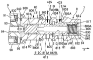
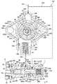
- the operating state (1st state) of the pump of 1st Embodiment is shown.
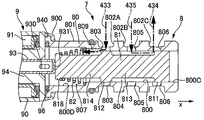
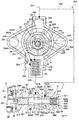
- the operating state (2nd state) of the pump of 1st Embodiment is shown.
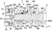
- the operating state (3rd state) of the pump of 1st Embodiment is shown.
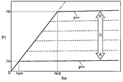
- the relationship between the engine rotation speed realized by the pump and the discharge pressure (main gallery hydraulic pressure) is shown.
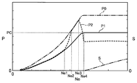
- achieves an example of the relationship between the oil pressure of each location, the moving amount
- a variable displacement pump (hereinafter referred to as a pump) 2 of the present embodiment is an oil pump used in a hydraulic oil supply system 1 of an internal combustion engine of a car.
- the pump 2 is installed at the front end of a cylinder block of an engine, etc., and lubricates other sliding parts of the engine and a variable valve device (a valve timing control device etc.) that variably controls the operating characteristics of the valves of the engine.
- Supply oil hydroaulic oil
- the system 1 includes an oil pan 400, an oil gallery (passage) 4, a pump 2, a pressure sensor (pressure measurement unit) 51, a rotation speed sensor (rotation speed measurement unit) 52, and an engine control unit A control unit 6 is provided.
- the oil pan 400 is a low pressure portion located in the lower part of the engine and storing hydraulic oil.
- the passage 4 is, for example, inside the cylinder block, and includes a suction passage 40, a discharge passage 41, a main gallery 42, a control passage 43, and a relief passage 44.
- One end of the suction passage 40 is connected to an oil pan 400 via an oil filter 401.
- the other end of the suction passage 40 is connected to the pump 2.
- One end of the discharge passage 41 is connected to the pump 2.
- the other end of the discharge passage 41 is connected to the oil filter 410.
- One end of the main gallery 42 is connected to the oil filter 410.
- the main gallery 42 can supply hydraulic oil to each sliding portion of the engine, the variable valve device, and the like.
- a pressure sensor 51 is installed in the main gallery 42.
- the relief passage 44 branches from the discharge passage 41 and can discharge the hydraulic oil to the oil pan 400.
- a relief valve 440 is installed in the relief passage 44.
- the pump 2 is a vane pump.
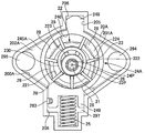
- the pump 2 includes a housing, a drive shaft 21, a rotor 22, a plurality of vanes 23, a cam ring 24, a spring (biasing member) 25, a first seal member 261, a second seal member 262, a pin 27, and a control mechanism 3.
- the housing has a housing body 20 and a cover.
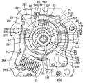
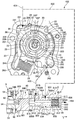
- FIG. 2 shows a portion of the pump 2 with the cover removed.
- the housing main body 20 internally includes a pump storage chamber 200, a suction port, and a discharge port.
- the pump storage chamber 200 is cylindrical with a bottom and opens at one side of the housing body 20.
- a hole (shaft accommodation hole) in which the drive shaft 21 is accommodated and a hole (pin hole) in which the pin 27 is fixed are opened on the bottom surface of the pump accommodation chamber 200.
- the cover is attached to one side of the housing body 20 by a plurality of bolts or the like, and closes the opening of the pump storage chamber 200.
- One end of the suction port opens to the outer surface of the housing body 20, and the other end of the suction passage 40 is connected.
- the other end of the suction port opens at the bottom of the pump storage chamber 200 as a suction port 201.
- the suction port 201 is a groove (concave portion) extending in the circumferential direction of the shaft receiving hole, and is on the opposite side of the pin hole with respect to the shaft receiving hole.
- the discharge port 202 is a groove (concave portion) extending in the circumferential direction of the shaft receiving hole, and is on the side of the pin hole with respect to the shaft receiving hole.
- the other end of the discharge port opens to the outer surface of the housing main body 20, and one end of the discharge passage 41 is connected.
- a groove corresponding to the suction port 201 and the discharge port 202 of the housing main body 20 is also present on the surface of the cover closing the pump storage chamber 200.
- the rotor 22, the plurality of vanes 23, the cam ring 24, and the spring 25 are inside the pump storage chamber 200.
- the drive shaft 21 is rotatably supported by the housing.
- the drive shaft 21 is connected to the crankshaft by a chain, a gear or the like.
- the rotor 22 is cylindrical.
- the rotor 22 is fixed to the drive shaft 21 in the circumferential direction, and rotates in the clockwise direction in FIG. 2 around the axis 22P.
- a back pressure chamber 223 is provided radially inward of the slit 222.
- the outer circumferential surface 220 of the rotor 22 has a convex portion 224 projecting radially outward.
- the slit 222 opens at the convex portion 224.
- the vanes 23 are accommodated in the slits 222.
- An annular member 230 is installed in the recess 221.
- the outer circumferential surface of the member 230 faces the proximal end of each vane 23.
- the inner circumferential surface 240 of the cam ring 24 is cylindrical.
- the outer periphery of the cam ring 24 has four protrusions 241 to 244 that project radially outward.
- a first seal member 261 is installed on the first protrusion 241.
- a second seal member 262 is installed on the second protrusion 242.
- the pin 27 is fitted to the third protrusion 243.
- the first protrusion 241 and the second protrusion 242 are on opposite sides of a straight line passing through the axial center of the pin 27 and the axial center 24P of the cam ring inner circumferential surface 240.
- One end of a spring 25 is installed on the fourth protrusion 244.
- a first control chamber 291, a second control chamber 292, and a spring accommodating chamber 293 are provided inside the pump accommodating chamber 200 between the housing and the cam ring 24.
- the first control chamber 291 is between the first protrusion 241 (first seal member 261) and the third protrusion 243 (pin 27) on the outer peripheral surface 245 of the cam ring 24, and the inner peripheral surface of the housing (pump storage chamber 200). Space between The first control chamber 291 is sealed by the first seal member 261 and the pin 27.
- a first region 246 on the cam ring outer peripheral surface 245 between the first seal member 261 and the pin 27 faces the first control chamber 291.
- the second control chamber 292 has a portion between the second protrusion 242 (second seal member 262) and the third protrusion 243 (pin 27) on the cam ring outer peripheral surface 245 and an inner peripheral surface of the housing (pump storage chamber 200). Space between The second control member 292 and the pin 27 seal the second control chamber 292. A second region 247 on the cam ring outer peripheral surface 245 between the second seal member 262 and the pin 27 faces the second control chamber 292.
- the area of the second area 247 (the angle occupied by the second area 247 in the circumferential direction of the cam ring 24, ie the circumferential direction of the axis 24P) is the area occupied by the first area 246 in the circumferential direction of the cam ring 24. Slightly larger than).
- the portion of the cam ring 24 corresponding to the second region 247 excluding the protrusion 242 is the first region 246 excluding the protrusions 241 and 243.
- the radial width is averaged at least in the region radially adjacent to the discharge port 202 than the corresponding portion (the axial end face of the cam ring 24 continuous with the first region 246 and facing the bottom surface of the pump storage chamber 200). large.
- the spring accommodating chamber 293 is located between the first projection 241 (first seal member 261) on the cam ring outer peripheral surface 245 and the second projection 242 (second seal member 262) via the fourth projection 244, It is a space between the inner circumferential surface of the storage chamber 200).
- the spring 25 is a compression coil spring. One end of the spring 25 is in contact with the circumferential one surface of the cam ring 24 in the fourth protrusion 244. The surface of the fourth protrusion 244 on the other side in the circumferential direction of the cam ring 24 faces the inner peripheral surface of the pump storage chamber 200 (spring storage chamber 293), and can abut on the inner peripheral surface. The other end of the spring 25 is installed on the inner peripheral surface of the pump storage chamber 200 (spring storage chamber 293).
- the spring 25 is in a compressed state, has a predetermined set load in an initial state in which the cam ring 24 is not actuated, and always biases the fourth protrusion 244 to the other side in the circumferential direction.
- the control mechanism 3 has a control passage 43 and a control valve 7.
- the control passage 43 has a first feedback passage 431 and a second feedback passage 432.
- One end side of the first feedback passage 431 branches from the main gallery 42.
- the other end of the first feedback passage 431 is connected to the first control chamber 291.
- the second feedback passage 432 includes a supply passage 433, a discharge passage 434, and a communication passage 435.
- One end side of the supply passage 433 branches from the first feedback passage 431.
- the other end of the supply passage 433 is connected to the control valve 7.
- One end of the discharge passage 434 is connected to the control valve 7.
- the other end of the discharge passage 434 is connected to the oil pan 400.
- One end of the communication passage 435 is connected to the control valve 7.
- the other end of the communication passage 435 is connected to the second control chamber 292.
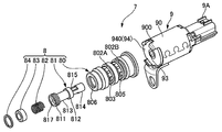
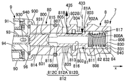
- the control valve 7 is a solenoid valve (solenoid valve), and has a valve portion 8 and a solenoid portion 9.
- the valve portion 8 is a three-way valve, and includes a cylinder (cylindrical portion) 80, a spool 81, a spring (spool urging member) 82, a retainer 83, and a stopper 84.
- the solenoid unit 9 includes a case 90, a coil 91, a plunger (movable core) 92, a rod 93, a fixed core 94, and a sleeve 95.
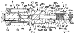
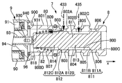
- the cylinder 80 has a cylindrical shape with an inner circumferential surface 800 stepped.
- Inner circumferential surface 800 has a large diameter portion 800A and a small diameter portion 800B.
- the diameter of the large diameter portion 800A is larger than the diameter of the small diameter portion 800B.
- the large diameter portion 800A is in the positive x-axis direction, and the small diameter portion 800B is in the negative x-axis direction.
- the outer circumferential surface 801 of the cylinder 80 has annular grooves 802A and 802B extending in a direction (circumferential direction) around the axial center of the cylinder 80.
- Inside the cylinder 80 there are a plurality of ports 803, 805, 806.
- the grooves 802A and 802B and the ports 803, 805 and 806 function as a part of the second feedback path 432 together with the space on the inner peripheral side of the cylinder 80.
- the supply port 803 and the communication port 805 are holes penetrating the cylinder 80 in the radial direction.
- a plurality of supply ports 803 are provided in the circumferential direction, and open to the large diameter portion 800A and the annular groove 802A.
- a plurality of communication ports 805 are provided in the circumferential direction, and open to the small diameter portion 800B and the annular groove 802B. The shape of the openings of these ports is circular.
- the discharge port 806 is an opening on the x-axis positive direction side of the cylinder 80.
- the other end of the supply passage 433 is connected to the annular groove 802A (supply port 803).
- the supply port 803 communicates with the discharge port 202 via the supply passage 433 (second feedback passage 432), the main gallery 42, and the discharge passage 41.
- the supply port 803 can introduce the hydraulic oil from the discharge port 202 into the inside of the cylinder 80.
- One end of a communication passage 435 is connected to the annular groove 802B (communication port 805).
- the communication port 805 communicates with the second control chamber 292 via the communication passage 435.
- the communication port 805 brings the inside of the cylinder 80 into communication with the second control chamber 292.
- One end of a discharge passage 434 is connected to the discharge port 806.
- the discharge port 806 can discharge the hydraulic oil from the inside of the cylinder 80 to the oil pan 400 via the discharge passage 434.
- the spool 81 is a cylindrical valve body (valve) located on the second feedback passage 432, is located inside the cylinder 80, and can reciprocate in the x-axis direction.
- the spool 81 has a first land portion 811, a second land portion 812, a first shaft portion 813, and a second shaft portion 814.
- the first land portion 811 is at the end of the spool 81 in the positive x-axis direction.
- the second land portion 812 is at the middle of the spool 81 in the x-axis direction.
- the first shaft 813 corresponds to a groove between the first land 811 and the second land 812 and connects the lands 811 and 812 to each other.
- the second shaft portion 814 is connected to the x-axis negative direction side of the second land portion 812.
- the diameter of the first land portion 811 is slightly smaller than the diameter of the large diameter portion 800A.
- the diameter of the second land portion 812 is slightly smaller than the diameter of the small diameter portion 800B.
- the diameter of the first land portion 811 is larger than the diameter of the second land portion 812.
- the diameters of the both shaft portions 813 and 814 are equal to each other and smaller than the diameter of the second land portion 812.
- the distance between the end of the first land portion 811 in the negative x-axis direction and the end of the second land portion 812 in the positive x-axis direction in the x-axis direction is the end of the supply port 803 in the negative x-axis direction.
- the x-axis dimension of the outer peripheral surface of the second land portion 812 is equal to the diameter of the communication port 805 (between the end of the opening of the communication port 805 in the small diameter portion 800B in the positive x-axis direction and the end in the negative x-axis direction Distance) is substantially the same (within tolerance).
- Inside the spool 81 there are holes 815 extending in the radial direction of the spool 81 and holes 816 extending in the x-axis direction.
- holes 815 There are a plurality of (two) holes 815, which are arranged in the circumferential direction (face in the radial direction) at a position adjacent to the second land portion 812 on the positive x-axis direction side of the second shaft portion 814.
- Hole 816 extends above the axial center of spool 81.
- the x-axis positive direction side of the hole 816 opens at the bottom of the recess 817, and the x-axis negative direction side of the hole 816 is connected to the plurality of holes 815.
- the retainer 83 is at the end of the large diameter portion 800A in the positive x-axis direction.
- the retainer 83 is cylindrical with a bottom, and has a bottom portion 831 and a cylindrical portion 832. At the center of the bottom 831 is a hole 830.
- the cylindrical portion 832 of the retainer 83 is fitted to the inner periphery (large diameter portion 800A) of the cylinder 80.
- the stopper 84 is annular and has a hole 840 at its center.
- the stopper 84 is fixed to the retainer 83 in the positive x-axis direction in the large diameter portion 800A.
- the surface on the x-axis negative direction side of the stopper 84 is in contact with the bottom 831 of the retainer 83.
- the first land portion 811 is in sliding contact with the large diameter portion 800A
- the second land portion 812 is in sliding contact with the small diameter portion 800B.
- a space 804 is defined between the first land portion 811 and the second land portion 812 inside the cylinder 80
- a space 807 is defined between the second land portion 812 and the solenoid portion 9 (fixed iron core 94).
- a space 808 is defined between the first land portion 811 and the retainer 83.
- the space 804 has a stepped cylindrical shape, and includes the inner peripheral surfaces 800A and 800B of the cylinder 80, the outer peripheral surface of the first shaft portion 813, the surface on the x-axis positive direction side of the second land portion 812, and the first land portion.
- the space 807 has a cylindrical shape, and the inner peripheral surface 800B of the cylinder 80, the outer peripheral surface of the second shaft portion 814, the x-axis negative direction surface of the second land portion 812, and the x-axis positive direction side of the fixed core 94. Between the faces 940 of the In the space 807, the hole 815 may be always open and the communication port 805 may be open.
- the space 808 is between the inner circumferential surface 800 A of the cylinder 80, the surface on the x-axis positive direction side of the second land portion 812 (including the recess 817), and the surface on the x-axis negative direction side of the retainer 83. Space 808 is in constant communication with exhaust port 806 via holes 830 and 840.
- the spring 82 is a compression coil spring and is installed in the space 808.
- the space 808 functions as a spring chamber for housing the spring 82.
- One end of the spring 82 is fitted to the inner peripheral side of the retainer 83, and one end of the spring 82 is in contact with the bottom 831 of the retainer 83.
- the other end of the spring 82 fits into the recess 817 of the spool 81, and the other end of the spring 82 contacts the bottom of the recess 817.
- the spring 82 is in a compressed state, has a predetermined set load in the initial state, and always biases the spool 81 in the negative x-axis direction.
- the solenoid portion 9 is coupled to the x-axis negative direction side of the valve portion 8 and closes an opening on the x-axis negative direction side of the cylinder 80.
- the solenoid unit 9 is an electromagnet that receives supply of current via the connector 9A and a wire.
- the coil 91 is fixed to the inner peripheral side of the case 90.
- the fixed core 94 is fixed to the x-axis positive direction side of the case 90 (coil 91), and the sleeve 95 is fixed to the x-axis negative direction side of the case 90 (coil 91).
- the x-axis positive direction end of the case 90 is fixed to the x-axis negative direction end of the cylinder 80.
- the O-ring 96 is installed in a compressed state between the surface 940 of the fixed core 94 and the surface on the negative side of the x-axis of the cylinder 80.
- the plunger 92 is made of a magnetic material, and is installed on the inner circumferential side of the sleeve 95 so as to be movable in the x-axis direction.
- the rod 93 is a separate member (separate) from the spool 81 and the plunger 92.
- the rod 93 is installed on the inner peripheral side of the fixed core 94 so as to be reciprocally movable in the x-axis direction.
- the rod 93 is cylindrical with a bottom.
- a plurality of (four) holes 930 penetrating the rod 93 in the radial direction are provided in the circumferential direction on the peripheral wall on both sides in the x-axis direction of the rod 93.
- At the bottom of the rod 93 in the positive x-axis direction there is a hole 931 penetrating the rod 93 in the x-axis direction.
- the surface on the x-axis positive direction side of the rod 93 (bottom) is in contact with the surface on the x-axis negative direction side of the spool 81 (second shaft portion 814).
- the flange portion at the x-axis negative direction end of the rod 93 contacts the surface of the plunger 92 on the x-axis positive direction side.
- the hole 930 allows both sides of the fixed core 94 in the x-axis direction to communicate with each other via the inner peripheral side of the rod 93. Thereby, the x-axis direction movement of the rod 93 with respect to the fixed core 94 is facilitated.
- the coil 91 generates an electromagnetic force by being energized.
- the plunger 92 is biased in the positive x-axis direction by the electromagnetic force.
- the rod 93 functions as a member for the solenoid unit 9 to bias the spool 81 in the positive x-axis direction.
- the plunger 92 biases the spool 81 in the positive x-axis direction through the rod 93 by the electromagnetic force.
- the solenoid unit 9 can continuously change the value of fm according to the value of the supplied current.
- the solenoid section 9 is controlled by pulse width modulation (PWM), and the current value is given by a duty ratio D.
- fm changes according to D (current value). For example, if D is less than a predetermined value D1 (dead zone), fm has a minimum value of zero (does not occur) regardless of the magnitude of D. If D is D1 or more and less than a predetermined value D2, fm changes according to D, and fm increases as D increases. When D is D2 or more, fm is the maximum value fmax regardless of the magnitude of D.
- the pressure sensor 51 detects (measures) the pressure (main gallery hydraulic pressure) P1 of the main gallery 42.
- the rotation speed sensor 52 detects (measures) the rotation speed Ne of the engine (crankshaft).
- the engine control unit (hereinafter, ECU) 6 controls the opening / closing operation of the control valve 7 (that is, the discharge amount of the pump 2) based on the input information and the built-in program. This controls the pressure and flow rate of the hydraulic oil supplied to the engine.
- the ECU 6 includes a receiving unit, a central processing unit (CPU), a read only memory (ROM), a random access memory (RAM), and a drive circuit, and these are mainly microcomputers mutually connected by a bidirectional common bus. Do.
- the receiving unit receives information on detection values of the pressure sensor 51 and the rotation speed sensor 52 and other engine operating conditions (oil temperature, water temperature, engine load, etc.).
- the ROM is a storage unit that stores control programs, map data, and the like.
- the CPU is an operation unit that performs an operation based on the read control program using information input from the receiving unit.
- the CPU performs calculation of the value of the current supplied to the control valve 7 (solenoid unit 9) and the like, and outputs a control signal according to the calculation result to the drive circuit.
- the drive circuit supplies power to the solenoid unit 9 according to a control signal from the CPU, and controls the current supplied to the solenoid unit 9.
- the drive circuit is a PWM control circuit, and changes the pulse width (duty ratio D) of the drive signal of the solenoid unit 9 according to the control signal.
- the flow of the hydraulic oil is shown by alternate long and short dashed lines in FIGS.
- the rotation of the crankshaft is transmitted to the drive shaft 21 of the pump 2 by a chain and gears.
- the drive shaft 21 rotationally drives the rotor 22.
- the rotor 22 rotates in the clockwise direction of FIGS.
- the components (pump components) including the rotor 22 and constituting the pump are rotationally driven to discharge the hydraulic oil introduced from the suction port and the suction port 201 from the discharge port 202 and the discharge port.
- the pump 2 sucks the working oil from the oil pan 400 via the suction passage 40 and discharges the working oil to the discharge passage 41.
- the pump 2 pumps hydraulic fluid to each part of the engine through the main gallery 42 connected to the discharge passage 41.
- the relief valve 440 opens when the pressure (discharge pressure) of the discharge passage 41 reaches a predetermined high pressure, and discharges the hydraulic fluid from the discharge passage 41 via the relief passage 44.
- the cam ring 24 forms a plurality of pump chambers (vane chambers) 28 by accommodating the rotor 22 and the plurality of vanes 23.
- the plurality of vanes 23 function as a pump arrangement.
- the vane chamber 28 is defined (defined) by the outer peripheral surface 220 of the rotor 22, the two adjacent vanes 23, the cam ring inner peripheral surface 240, the bottom surface of the pump storage chamber 200, and the side surface of the cover.
- the volume of each vane chamber 28 can be changed as the rotor 22 rotates, and the volume of each vane chamber 28 is increased or decreased by rotation to perform a pumping action.
- the suction port 201 opens in a range (intake region) where the volume of the vane chamber 28 increases (in accordance with the rotation of the rotor 22).
- the vane chamber 28 in the suction area sucks the hydraulic oil from the suction port 201.
- the discharge port 202 opens in a range (discharge region) in which the volume of the vane chamber 28 decreases (in accordance with the rotation of the rotor 22).
- the vane chamber 28 in the discharge area discharges the hydraulic oil to the discharge port 202.
- the difference between the maximum volume and the minimum volume of the vane chamber 28 determines the theoretical discharge amount (discharge amount per rotation) of the pump 2, that is, the capacity.
- the amount of change in volume of the vane chamber 28 (the difference between the maximum volume and the minimum volume) is variable.
- the cam ring 24 is a movable member (movable member) inside the pump storage chamber 200, and can rotate about the pin 27.
- the pin 27 functions as a pivot portion (fulcrum point) inside the pump storage chamber 200.
- the difference (the amount of eccentricity ⁇ ) between the shaft center 22P of the rotor 22 and the shaft center 24P of the cam ring inner circumferential surface 240 changes.
- the amount of change (volume change amount) of the volume of each of the plurality of vane chambers 28 when the rotor 22 rotates changes.
- the pump 2 is a variable displacement type, and it is possible to increase ⁇ to increase the capacity and to decrease ⁇ to decrease the capacity.
- the volumes of the first control chamber 291 and the second control chamber 292 can change when the cam ring 24 moves.
- the suction area and the discharge area extend across the axial center 22P of the rotor 22.
- the first control chamber 291 and the second control chamber 292 are adjacent to the vane chamber 28 and the discharge port 202 in the discharge area with the cam ring 24 interposed therebetween.
- the pressure of the discharge port 202 is introduced into the back pressure chamber 223, and by pushing the vanes 23 from the slits 222, the liquid tightness of the vane chamber 28 is improved. Even when the engine rotational speed is low and the centrifugal force and the pressure in the back pressure chamber 223 are low, the annular member 230 pushes the vanes 23 out of the slits 222, whereby the liquid tightness of the vane chamber 28 is improved.
- the cam ring 24 has one side in the rotational direction about the pin 27 (the clockwise direction in FIG. 5 due to the spring 25).
- the amount of increase or decrease in the volume of each of the plurality of vane chambers 28 increases, and the eccentricity ⁇ increases. Side). Let this spring force be Fs.
- the cam ring 24 receives the pressure of the hydraulic oil inside the first control chamber 291.
- the first region 246 of the cam ring outer peripheral surface 245 functions as a pressure receiving surface that receives the pressure of the first control chamber 291.
- the cam ring 24 is rotated by the hydraulic pressure on the other side in the rotational direction about the pin 27 (counterclockwise in FIG. 5), and the increase and decrease of the volume of each of the plurality of vane chambers 28 decreases. ).
- the force (oil pressure) by this hydraulic pressure be Fp1.
- the volume of the first control chamber 291 increases when the cam ring 24 moves to the other side in the rotational direction (a direction to resist the biasing force Fs of the spring 25).
- the cam ring 24 receives the pressure of the hydraulic oil in the second control chamber 292.
- the second region 247 of the cam ring outer peripheral surface 245 functions as a pressure receiving surface that receives the pressure of the second control chamber 292.
- the cam ring 24 is biased to one side in the rotational direction by the hydraulic pressure.
- the force (oil pressure) by this hydraulic pressure is Fp2.
- the volume of the second control chamber 292 increases when the cam ring 24 moves to one side in the rotational direction (the same direction as Fs).
- the rotational direction position ( ⁇ or capacity) of the cam ring 24 is mainly determined by Fp1, Fp2, and Fs.
- Fp1 becomes larger than the sum of Fp2 and Fs (Fp2 + Fs)
- Fp2 + Fs the cam ring 24 swings to the other side in the rotational direction, and ⁇ (capacity) decreases.
- Fp1 becomes smaller than (Fp2 + Fs)
- the cam ring 24 swings to one side in the above rotational direction, and ⁇ (capacity) increases.
- the cam ring 24 stops at a position where Fp1 and (Fp2 + Fs) are balanced.
- the hydraulic oil supplied from the discharge port 202 to the main gallery 42 is introduced into the first control chamber 291 via the first feedback passage 431.
- the pressure of the first control chamber 291 is substantially the same as the hydraulic pressure P1 of the main gallery 42 (unless considering the pressure loss).
- the hydraulic oil supplied from the discharge port 202 to the main gallery 42 can be introduced into the second control chamber 292 via the second feedback passage 432 (supply passage 433, control valve 7, communication passage 435).
- the hydraulic oil in the second control chamber 292 can be discharged through the communication passage 435 and the discharge passage 434.
- the pressure in the second control chamber 292 is P2.
- the control valve 7 can control the introduction of the hydraulic fluid to the second control chamber 292 and the discharge of the hydraulic fluid from the second control chamber 292.
- the spool 81 moves to switch the connection state between the communication passage 435 and the supply / discharge passage 433 and 434.
- the space 804 of the cylinder 80 can function as a passage of hydraulic fluid from the supply passage 433 to the communication passage 435 by connecting the supply port 803 and the communication port 805.
- the space 807, the holes 815 and 816 of the spool 81, the space 808, the hole 830 of the retainer 83, and the hole 840 of the stopper 84 connect the communication port 805 and the discharge port 806, thereby actuating oil from the communication passage 435 to the discharge passage 434 Can act as a passage for
- the second land portion 812 changes the opening area of the communication port 805 in the inner circumferential surface 800 (spaces 804 and 807) of the cylinder 80.
- the movement of the spool 81 switches the connection and disconnection between the supply passage 433 and the communication passage 435, and the connection and disconnection between the communication passage 435 and the discharge passage 434.
- the supply port 803 opens into the space 804.
- the second land portion 812 opens the communication port 805 to the space 804 in a state where the opening of the communication port 805 in the space 807 is closed.
- the second land portion 812 opens the communication port 805 to the space 807 in a state in which the opening of the communication port 805 in the space 804 is closed.
- the opening of the supply port 803 in the space 804 may be partially blocked in response to the movement of the spool 81.
- the discharge passage 434 may not be provided, and the discharge port 806 may be opened directly to the oil pan 400. Further, the discharge port 806 may be in communication with the low pressure portion, and may be in communication with the side of the suction port (for which suction negative pressure is generated) as well as the oil pan 400 (atmospheric pressure).
- the spool 81 switches the connection and disconnection between the main gallery 42 (via the communication passage 435 and the supply passage 433) and the second control chamber 292 by switching the connection state of the passages 433-435.
- the communication and blocking between the second control chamber 292 (via the communication passage 435 and the discharge passage 434) and the oil pan 400 are switched.
- the communication passage 435 and the supply passage 433 are connected and the main gallery 42 and the second control chamber 292 are communicated.
- the hydraulic oil from the discharge port 202 is introduced into the second control chamber 292 (first state).
- the communication passage 435 is not connected to any of the passages 433 and 434.
- the second control chamber 292 is in a closed state (closed state) in which the second control chamber 292 does not communicate with either the main gallery 42 or the oil pan 400, and supply of hydraulic fluid to the second control chamber 292 and hydraulic fluid from the second control chamber 292 Discharge is suppressed (third state).
- the opening area of the communication port 805 in the space 804 is smaller than in the first state. Further, compared with the second state, the opening area of the communication port 805 in the space 807 is smaller.
- the holes 815 and 816 of the spool 81 function as communication holes that allow the space 808 on the x-axis positive direction side of the spool 81 (first land portion 811) to communicate with the space 807 on the x-axis negative direction side of the second land portion 812. . Therefore, the space 807 and the space 808 have the same pressure (atmospheric pressure).
- the space 804 functions as a pressure chamber that generates fp. That is, the main gallery hydraulic pressure P1 is introduced into the space 804.
- the stepped portion between the first land portion 811 and the first shaft portion 813 faces the x-axis negative direction side, and functions as a first pressure receiving surface 81A that receives the pressure of the hydraulic oil in the space 804.
- the stepped portion between the second land portion 812 and the first shaft portion 813 faces the x-axis positive direction side, and functions as a second pressure receiving surface 81 B that receives the pressure of the hydraulic oil in the space 804.
- the area of the first pressure receiving surface 81A is larger than the area of the first pressure receiving surface 81B. Therefore, when the hydraulic pressure P1 is generated in the space 804, the hydraulic pressure fp of a size obtained by multiplying the area difference between both surfaces 81A and 81B by P1 acts on the spool 81 to bias the spool 81 in the x-axis positive direction. Further, the spool 81 is biased by the spring 82 in the negative x-axis direction. Let this spring force be fs.
- the spool 81 moves in the positive x-axis direction, and when fp is smaller than fs, the spool 81 moves in the negative x-axis direction, and the spool 81 stops at a position where fp and fs balance.
- fm is zero
- the rod 93 is not biased in the positive x-axis direction, so the spool 81 is separated from the rod 93.
- the separation / contact of the rod 93 with respect to the spool 81 is facilitated by the hole 931 at the end face of the rod 93 in the x-axis positive direction.
- the rotational speed of the pump 2 is also equal to or less than a predetermined value (corresponding to NeB), and P1 is equal to or less than the predetermined value PB. Since P1 is equal to or less than PB, fp is equal to or less than a predetermined value, and the spool 81 is within a predetermined distance from the initial position in the positive x-axis direction. Thus, the first state is realized.
- the second control chamber 292 is pressurized.
- the rotational speed of the pump 2 is also higher than the predetermined value (corresponding to NeB).
- the main gallery hydraulic pressure P1 tries to become higher than the predetermined value PB
- fp becomes larger than the predetermined value
- the spool 81 moves from the initial position in the positive x-axis direction by more than the predetermined distance.
- the second control chamber 292 is decompressed, (Fp 2 + Fs) acting on the cam ring 24 becomes smaller than Fp 1, the cam ring 24 swings to the other side in the rotational direction, and the eccentricity ⁇ decreases.
- P1 acts as a pilot pressure and acts on the spool 81, whereby the state of the operation of the spool 81 (the supply and discharge of the hydraulic oil to the second control chamber 292) is feedback controlled, and the ⁇ (volume) is adjusted. Be done.
- P1 in the region of Ne higher than NeB, P1 is maintained at a hydraulic pressure in a predetermined range of PB and its vicinity regardless of Ne.
- control oil pressure P ** P1 that is automatically kept in the predetermined range regardless of Ne. Since the above control of P1 is performed by switching the port 805 of the control valve 7 and the like, it is not affected by the spring constant of the spring 25 of the cam ring 24.
- the solenoid unit 9 can change the thrust fm continuously.
- the solenoid unit 9 functions as a proportional electromagnet that can control fm steplessly according to the value of the supplied current (duty ratio D). Basically, if D is increased, fm will be increased.
- the position of the spool 81 in the x-axis direction with respect to the cylinder 80 is mainly determined by fm, oil pressure fp and spring force fs.
- fm oil pressure
- fp spring force
- the solenoid section 9 has a function to change P1 when the spool 81 starts moving, in other words, substantially (substantially) change the load fs of the spring 82 by changing fm. fm assists fp, and with lower P1 (smaller fp), the spool 81 is moved in the positive x-axis direction to realize the second state. That is, P ** controlled by the above operation of the spool 81 is lowered. Therefore, as shown in FIG. 8, according to the magnitude of D, P1 (P **) can be controlled to a value lower than PB. As D (i.e. fm) is larger, P ** is lower, and as D is smaller, P ** is higher. When D is D2 or more (fm is the maximum value fmax), P ** is the minimum value PA.
- a control program of the ECU 6 is executed to control the control valve 7.
- the ECU 6 changes the value (duty ratio D) of the current supplied to the solenoid unit 9 in accordance with the operating state of the engine (engine rotation speed Ne, etc.), thereby the main gallery hydraulic pressure P1 (control hydraulic pressure P **) and discharge.
- the flow rate can be freely changed (controlled).
- the characteristics of P1 and the discharge flow rate with respect to Ne can be easily brought close to the desired characteristics. As a result, power loss due to unnecessary discharge pressure increase (flow rate increase) can be suppressed, and fuel consumption can be improved.
- the ECU 6 changes D such that the difference between P1 and the required hydraulic pressure demand P * falls within a predetermined range with an arbitrary Ne in a region of Ne higher than a preset value NeA ( ⁇ NeB).
- P * is the hydraulic pressure required to operate the variable valve system, the required hydraulic pressure of the oil jet for cooling the engine piston, the hydraulic pressure required to lubricate the bearings of the crankshaft, etc. It is preset as an ideal value.
- the ROM of the ECU 6 stores P *, which changes according to Ne, and D, which changes according to Ne, as a map. In the map, D is set to zero when Ne is less than NeA.
- Ne is less than NeA
- no current is supplied to the solenoid section 9, so that the first state is realized, and the amount of eccentricity ⁇ becomes maximum. Therefore, after the start of the engine start, P1 can be promptly raised according to the increase of Ne, and for example, the operation response of the variable valve device can be secured.
- the duty ratio D is set to be discretely changed in each predetermined range of Ne in the region of the engine rotational speed Ne higher than the predetermined value NeA. That is, in a certain range NeI (n-1) of Ne, D is a certain constant value D (n-1) (hereinafter, parentheses are subscripts and n is a natural number). In another adjacent range NeI (n), D is another constant value D (n). In the range NeI * of Ne between NeI (n) and NeI (n-1), D switches between D (n-1) and D (n).
- D switches from D (n-1) to D (n) will be described as an example.
- Ne is in NeI *, basically (except during closing control described later), D is D (n) after switching.
- the above operation of the control valve 7 (spool 81) realizes the control oil pressure P ** (n-1) in which the amount of eccentricity ⁇ (capacity) corresponds to D (n-1). It is planned to change from the size of to a size for realizing P ** (n) according to D (n).
- Ne changes via a plurality of NeI (n)
- the characteristic of P1 that changes stepwise is realized.
- D is preset for Ne so that this characteristic approaches the characteristic of the required hydraulic pressure P * for Ne (predetermined required characteristic).
- the change of D with respect to Ne in the map is set such that the difference between P1 in the realized characteristic and P1 (P *) in the required characteristic is within a predetermined range with arbitrary Ne (> NeA). Ru.
- the ECU 6 When switching the duty ratio D between D (n-1) and D (n), the ECU 6 performs closing control.
- the closing control substantially realizes the third state for at least a fixed period during the switching, and the pressure of the second control chamber 292 is increased by the hydraulic oil leaking from the side of the discharge port 202 to the second control chamber 292.
- Control to make The ECU 6 sets the duty ratio D (s) in the confinement control so as to satisfy the following condition (C1).
- C1 The position of the spool 81 (second land portion 812) is determined by the communication passage 435 and the supply passage owing to the hydraulic pressure fp by the main gallery hydraulic pressure P1 at the start of the closing control and the solenoid thrust fm according to D (s).
- D (s) can be made constant if the following condition (C2) is satisfied. (C2) During the closing control, regardless of the change in P1 (corresponding to the change in engine speed Ne) (the change in Fp), the position of the spool 81 (second land portion 812) The communication with the passages 433 and 434 can be sufficiently blocked. When D (s) is constant, D (s) can also be D (n) after switching.
- the start timing of the closing control (for example, Ne for starting the control) is set (using experiment, simulation or the like) so as to satisfy the following condition (C3) together with the above condition (C2).
- C3 When P1 reaches P ** corresponding to D (n) after switching or in the vicinity thereof, the position of the spool 81 (second land portion 812) can communicate the communication passage 435 with the discharge passage 434 (The second state can be realized).
- the main gallery hydraulic pressure P1 is increased from zero to PC according to the engine speed Ne rising from zero, and thereafter maintained at a predetermined value PC (control hydraulic pressure P ** (1) Assume a scene).
- PC is a required hydraulic pressure P * that is between the predetermined value PA and the predetermined value PB and close to PA (see FIG. 8).
- S indicates the amount of movement (stroke) from the initial position of the cam ring 24.
- the ECU 6 sets the duty ratio D to zero within the range where Ne is less than the predetermined value NeA. D is switched between zero and D (1) in the range where Ne is greater than NeA and less than Ne4. Basically, D is set to D (1) after switching.
- D is maintained at D (1) in the range where Ne is greater than Ne4.
- the magnitude of the control hydraulic pressure PB according to which the amount of eccentricity ⁇ (capacity) corresponds to D 0 by the operation of the control valve 7 (spool 81).
- it is scheduled to change to a magnitude for realizing the control hydraulic pressure PC according to D D (1).
- P1 is less than PC (Ne less than Ne4)
- (fp + fm) is smaller than the value that can realize the second state. Therefore, the first state should be realized by the control valve 7 and ⁇ should be maximum. That is, it is planned that P1 changes according to Ne with a gradient corresponding to the maximum capacity.
- the ECU 6 executes the closing control in the range of the engine speed Ne from Ne1 to Ne3 (NeA ⁇ Ne1 ⁇ Ne3).
- the spool 81 (second land portion 812) is slightly on the negative side in the x-axis direction than the closing position (substantially
- the duty ratio D (s) in the closing control is set so that three states are realized).
- the sum (fp + fm) of the hydraulic pressure fp and the solenoid thrust fm according to the main gallery hydraulic pressure P1 (a set value in the map, which may be a detected value) when Ne is Ne1 is “communication in the space 807
- the communication port 805 when the engine rotational speed Ne is Ne1, the communication port 805 is slightly opened in the space 804, and the second control chamber 292 and the supply passage 433 communicate with each other.
- the opening area of the communication port 805 in the space 804 is smaller than when Ne is less than Ne1 (before the start of the confinement control). That is, the passage connecting the second control chamber 292 and the supply passage 433 is narrowed.
- the main gallery hydraulic pressure P1 slightly rises in response to the rise of Ne, and the oil pressure fp slightly rises along with this, the spool 81 slightly moves in the x-axis positive direction side .
- the degree to which the second land portion 812 blocks the opening of the communication port 805 in the space 804 is increased.
- the communication port 805 opens slightly in the space 807, and the second control chamber 292 and the discharge passage 434 communicate. Therefore, the third state is substantially realized in the range where Ne is from Ne1 to Ne3. In other words, a closed state in which the second control chamber 292 does not communicate with the main gallery 42 or the oil pan 400 is substantially realized.
- some openings of the communication port 805 in the spaces 804 and 807 can discharge the hydraulic oil from the second control chamber 292 to the supply passage 433 or the discharge passage 434 through the communication passage 435, the amount is limited.
- the amount of hydraulic fluid leaking from the discharge port 202 or the like into the second control chamber 292 is more than the amount of hydraulic fluid that can be discharged from the second control chamber 292 due to the slight opening of the communication port 805 in the spaces 804 and 807.
- P2 can rise. In the range of Ne from Ne1 to Ne2, P2 rises toward P0. When Ne is Ne2, P2 reaches P0, and P2 matches P0 until Ne becomes Ne3. As P2 is pressurized toward P0, Fp2 is increased.
- the second state is realized when the engine rotational speed Ne is in the range from Ne3 to Ne4, and the second control chamber 292 and the discharge passage 434 communicate with each other.
- the pressure P2 of the second control chamber 292 drops from the pump internal pressure P0.
- the main gallery hydraulic pressure P1 reaches a predetermined value PC (control hydraulic pressure P **).
- PC control hydraulic pressure P **.
- control mechanism 3 adjusts the opening area of communication port 805 in spaces 804 and 807, and P1 reaches P ** for at least a fixed period until main gallery hydraulic pressure P1 reaches control hydraulic pressure P **.
- the third state is substantially realized by reducing the opening area (average in time) as compared to the later.
- the pressure of the second control chamber 292 can be increased using hydraulic oil that leaks from the discharge port 202 or the like into the interior of the second control chamber 292.
- Fp2 oil pressure
- P2 of the second control chamber 292 it is possible to cancel the load (in the direction of decreasing ⁇ ) by the breakdown of pressure balance. Therefore, it is possible to suppress the unexpected operation of the cam ring 24 (not by the operation of the control valve 7), to suppress the failure to achieve P **, and to realize the required hydraulic pressure P * more reliably. Therefore, the controllability of the pump 2 can be improved. It is possible to stably supply P * to the engine by suppressing the shortage of discharge amount due to an unexpected decrease of ⁇ .
- the said scene demonstrated using FIG. 9 is an example when the said conditions (C1) (C2) (C3) are satisfy
- the ECU 6 may perform the same closing control not only at a scene where the engine rotational speed Ne (main gallery hydraulic pressure P1) rises but also at a scene where Ne (P1) falls.
- the control hydraulic pressure P ** is changed from P ** (n-1) to P ** (n) (the duty ratio D is set to D (n-1) and D, not limited to the case where P1 is increased from zero to a predetermined value PC).
- similar closing control may be performed in a scene (switched between (n)). In this case, D (s) may be different from D (n).
- D (s) may be changed to keep the spool 81 at or near the squeezed-in position in response to the change of P1 (the change of the oil pressure fp).
- the closing control may be ended before the end of the switching of D. For example, if it is determined that the pressure P2 in the second control chamber 292 has sufficiently increased due to the closing control, D may be D (s) to D (n) before Ne reaches NeI (n). Conversely, the closing control may be executed until the end of switching D. That is, D may be D (s) until the end of D switching, and may be D (s) to D (n) at the end of switching. Also, the closing control may be started simultaneously with the start of the switching of D.
- D may be D (s) at the start of D switching.
- the closing control in an engine operating condition where the cam ring 24 may malfunction due to pressure unbalance between the vane chambers 28.
- the operating condition (range of Ne, etc.) of the engine in which the cam ring 24 may malfunction is grasped in advance, and the closing control is executed only in this condition. Further, from the viewpoint of suppressing frequent control, only when the above-mentioned malfunction of the cam ring 24 actually occurs, this may be corrected by the closing control.
- Ne (P1) rises
- P1 pressure sensor 51 or the like detects that P1 does not rise according to Ne before P1 reaches P ** (n)
- P1 a parameter for changing the current (D) supplied to the solenoid unit 9 according to the engine operating condition
- Ne not only Ne but also the number of revolutions of the pump, P1, oil temperature, water temperature, engine load, etc. may be used.
- the mechanical configuration of the pump 2 can be changed variously.
- the configuration of the pump 2 of the present embodiment the following effects can be obtained.
- the cam ring 24 can swing around a fulcrum (pin 27) inside the pump storage chamber 200. Therefore, the range in which the cam ring 24 operates can be suppressed, and the pump 2 can be miniaturized.
- the volume of the first control chamber 291 increases when the cam ring 24 moves in the direction to resist the biasing force Fs of the spring 25. That is, the spring 25 generates Fs in the direction opposite to the oil pressure Fp1 and functions as a return spring. For this reason, the cam ring 24 can be returned to the initial position when Fp1 is zero.
- the initial position of the cam ring 24 is on the side where the amount of eccentricity ⁇ is large. Therefore, when the main gallery hydraulic pressure P1 is low, P1 can be raised promptly.
- the volume of the second control chamber 292 increases when the cam ring 24 moves in the direction of Fs. That is, Fp2 acts in the same direction as Fs. Fp1 and Fp2 act in opposite directions.
- the hydraulic oil may be introduced directly from the discharge port 202 to the first control chamber 291 without passing through the main gallery 42.
- the hydraulic fluid is introduced to the second control chamber 292 via the supply passage 433.
- the supply passage 433 (at least part of it) is outside the housing of the pump 2. Even if the pressure P2 in the second control chamber 292 is maximum (main gallery hydraulic pressure P1) due to the pressure loss in the supply passage 433, the pressure in the discharge port 202, in other words, the pressure in the vane chamber 28 in the discharge area (internal pressure of the pump) P0 It becomes lower than.
- the area of the second region 247 receiving the pressure P2 of the second control chamber 292 on the cam ring outer peripheral surface 245 may be the same as the area of the first region 246 receiving the pressure P1 of the first control chamber 291. It may be smaller than the area of 246. In the present embodiment, the area of the second region 247 is larger than the area of the first region 246. Therefore, large oil pressure Fp2 can be realized at low P2. For example, even when P1 and P2 are the same, Fp2 is larger than the oil pressure Fp1. For this reason, even if the balance of the pressure acting on the cam ring 24 from the vane chamber 28 in the discharge region is somewhat lost, the cam ring 24 is biased in the direction of increasing the amount of eccentricity .DELTA. it can.
- the structure of the valve portion 8 of the control valve 7 may be a poppet type or a slide type.
- the structure is in the form of a spool. Accordingly, the multiport valve can be adapted to a wide range of hydraulic pressure while simplifying the structure.
- the cylinder 80 has a supply port 803, a communication port 805, and an exhaust port 806.
- the supply port 803 is connected to the supply passage 433 and can introduce the hydraulic oil supplied from the discharge port 202 to the main gallery 42 into the inside of the cylinder 80.
- the communication port 805 is connected to the second control chamber 292, and brings the inside of the cylinder 80 into communication with the second control chamber 292.
- the discharge port 806 is connected to the discharge passage 434 and can discharge the hydraulic oil from the inside of the cylinder 80.
- the spool 81 has a second land portion 812 capable of changing the opening area of the communication port 805 in the inner circumferential surface 800 of the cylinder 80.
- the spool 81 is inside the cylinder 80 and is capable of reciprocating in the x-axis direction, and receives the pressure P1 of the hydraulic fluid introduced from the supply port 803 into the cylinder 80. With such a simple configuration of the spool valve, the valve unit 8 can control the pressure P2 of the second control chamber 292.
- the spool 81 is biased in the positive x-axis direction by the main gallery hydraulic pressure P1 (oil pressure fp). Further, the spool 81 is biased in the negative x-axis direction by a spring 82 (spring force fs). That is, since the spring 82 acts in the opposite direction to fp and functions as a return spring, it is possible to return the spool 81 to the initial position when fp is zero.
- the initial position of the spool 81 is in the direction to realize the first state, that is, in the direction to increase the eccentricity ⁇ by increasing the pressure in the second control chamber 292. Therefore, when P1 is low, P1 can be raised promptly.
- the control valve 7 has a solenoid unit 9.
- the solenoid unit 9 can generate an electromagnetic force fm for controlling the position of the valve (the position of the spool 81 in the x-axis direction). Therefore, it is easy to control the spool 81 in the closing position and its vicinity, and the closing control can be easily performed.
- the solenoid unit 9 can change the size of fm according to the duty ratio D. Therefore, it is possible to freely control the spool 81 to the closed position and its vicinity.
- the method of transmitting the force from the plunger 92 to the valve body (spool 81) may be a pilot type (indirect operation type). In the present embodiment, the method is direct acting (direct acting).
- the solenoid unit 9 can generate fm that directly biases the spool 81.
- the member (rod 93) for biasing the spool 81 by the solenoid unit 9 may be integral with the spool 81.
- the rod 93 is a member separate from the spool 81 and is separable from the spool 81. Therefore, the valve unit 8 can be automatically operated according to the main gallery hydraulic pressure P1 even when the solenoid unit 9 does not operate due to disconnection or the like. Thereby, the predetermined control oil pressure P ** can be realized.
- the solenoid unit 9 may be capable of generating an electromagnetic force fm that biases the spool 81 in the x-axis negative direction side, that is, in the same direction as the spring 82 (spring force fs).
- the solenoid unit 9 reduces the spool 81 to the x-axis positive direction side, that is, the same direction as the main gallery hydraulic pressure P1 (the direction to assist the oil pressure fp) and the direction opposite to the spring 82 (fs To generate fm, which biases the Thereby, a fail safe function is realized. That is, as shown in FIG. 8, as the duty ratio D (fm) is smaller, the control hydraulic pressure P ** is higher, and when D is zero, P ** is the highest PB. Therefore, even when the solenoid unit 9 fails, P ** is at a high pressure, and the hydraulic oil can be supplied to the engine at the maximum pressure PB.
- the x-axis direction dimension of the second land portion 812 may be larger or smaller than the diameter (x-axis direction dimension) of the opening of the communication port 805. That is, when the spool 81 is in a predetermined range in the x-axis direction, the communication port 805 overlapping with the second land portion 812 may be slightly opened in both of the spaces 804 and 807 or closed to both.
- the x-axis direction dimension of the second land portion 812 is substantially the same as the diameter (x-axis direction dimension) of the opening of the communication port 805. Accordingly, the communication / blocking between the communication port 805 and the spaces 804 and 807 is quickly switched according to the movement of the spool 81. Therefore, the responsiveness of control can be improved.
- the second state is suppressed in the first state, and the first state is suppressed in the second state. Therefore, the responsiveness of control can be improved, and the third state (closed state) can be realized more easily.
- the shape of the opening of the communication port 805 or the like on the inner circumferential surface 800 of the cylinder 80 is the above in the circumferential direction (the direction around the axial center) of the cylinder 80 than the dimension of the opening in the axial direction
- the size of the opening may be a rectangle, an ellipse, or the like.
- the shape of the opening of the communication port 805 is circular. That is, the dimension of the opening in the circumferential direction of the cylinder 80 is near zero near the end of the opening in the axial direction of the cylinder 80 and gradually increases toward the center of the opening in the axial direction of the cylinder 80.
- the rate of change is relatively small.
- the opening area of the communication port 805 in the space 804, 807 changes suddenly according to the movement of the spool 81.
- a change in flow rate of hydraulic fluid flowing from the space 804 into the second control chamber 292 through the communication port 805 in accordance with the movement of the spool 81, and an operation flowing from the second control chamber 292 into the space 807 through the communication port 805 The change in oil flow rate is moderate due to the throttling effect. Since the fluctuation of the pressure P2 in the second control chamber 292 is suppressed, the behavior of the spool 81 and the cam ring 24 is stabilized, and the fluctuation of the main gallery hydraulic pressure P1 is reduced.
- the area of the first pressure receiving surface 81A of the spool 81 is larger than the area of the second pressure receiving surface 81B. Since there is a difference in area between the two pressure receiving surfaces 81A and 81B, it is possible to generate an oil pressure fp for urging the spool 81 in the x-axis direction with a single pressure P1.
- the structure of the control valve 7 can be simplified because it is not necessary to apply a plurality of pressures to the spool 81 to generate fp.
- the first pressure receiving surface 81A and the second pressure receiving surface 81B face each other in the x-axis direction and, together with the inner circumferential surface 800 of the cylinder 80, define a space 804 into which hydraulic fluid from the discharge port 202 is introduced.
- control valve 7 can be simplified because it is sufficient to have a single space 804 for generating fp.
- a space 804 for generating fp is at the middle of the spool 81 in the x-axis direction and not at the end of the spool 81 in the x-axis direction. Therefore, the increase in the x-axis direction dimension of the control valve 7 can be suppressed.
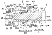
- the configuration of the control valve 7 differs from that of the first embodiment.
- the x-axis direction dimension of the second land portion 812 of the spool 81 is larger than the diameter (x-axis direction dimension) of the opening of the communication port 805 on the inner circumferential surface 800 of the cylinder 80. Both sides of the second land portion 812 in the x-axis direction are tapered.
- the second land portion 812 has a main body 812A, an end 812B on the positive side in the x-axis direction, and an end 812C on the negative side in the x-axis direction.
- the main body 812A is cylindrical.
- the x-axis direction dimension of the main body 812A is the same as the x-axis direction dimension of the second land portion 812 (communication port 805) of the first embodiment.
- the shapes of the end portions 812B and 812C are truncated cones.
- the diameter of the end portions 812B and 812C is smaller than that of the main portion 812A, and gradually decreases with distance from the main portion 812A in the x-axis direction.
- the outer peripheral surface of the end portion 812B has a shape in which all in the circumferential direction (direction around the axial center of the spool 81) is scraped off (chamfered), and the diameter gradually decreases toward the positive x-axis direction It is a state.
- the outer peripheral surface of the end portion 812C has a shape in which the entire portion in the circumferential direction is scraped off, and is tapered such that the diameter gradually decreases toward the negative side in the x-axis direction.
- the main body 812A is in the same position as the second land portion 812 when the spool 81 is in the initial position in the first embodiment.
- the end 812 B is in the x-axis direction between the end of the communication port 805 on the positive side in the x-axis direction and the end on the negative side of the x-axis. As shown in FIG.
- the x-axis direction dimension of the second land portion 812 is larger than the x-axis direction dimension of the opening of the communication port 805. Therefore, when the spool 81 is moved by the change of the oil pressure Fp1 and the first state and the second state are switched, it is possible to suppress excessive frequent switching between the communication port 805 and the spaces 804 and 807.
- the communication passage 435 can be substantially disconnected from either of the passages 433 and 434. Therefore, the third state can be realized more easily, and the confinement control can be performed more easily.
- the size of the gap between the outer peripheral surface of the end portions 812B and 812C and the inner peripheral surface 800 of the cylinder 80 corresponds to the flow passage cross-sectional area of the flow passage, and moves away from the main portion 812A in the x-axis direction , Increases. Therefore, the flow rate change can be more effectively made gentle.
- the flow passage may be at least a part of the spool 81 (second land portion 812) in the circumferential direction.
- the outer peripheral surfaces of the end portions 812B and 812C have a shape in which the entire circumferential direction is scraped off. In other words, the flow passage extends over the entire circumferential direction of the spool 81 (second land portion 812).
- the processing accuracy of the outer peripheral surfaces of the end portions 812B and 812C can be improved, so that the above-described effects can be improved. Further, since it is not necessary to match the position of the flow passage (the gap) and the position of the opening of the communication port 805 in the circumferential direction, the assemblability of the spool 81 to the cylinder 80 can be improved.
- the other effects and advantages are the same as in the first embodiment.
- the inner circumferential surface 800 of the cylinder 80 has a main body portion 800C and a large diameter portion 800D.
- the diameter of the large diameter portion 800D is larger than the diameter of the main portion 800C.
- the main body portion 800C is on the x-axis positive direction side, and the large diameter portion 800D is on the x-axis negative direction side.
- the outer circumferential surface 801 of the cylinder 80 has annular grooves 802A, 802B, and 802C.
- the annular grooves 802A, 802B, and 802C are arranged in this order from the x-axis negative direction side to the x-axis positive direction side.
- the supply port 803, the communication port 805, and the discharge port 806 are holes which penetrate the cylinder 80 in the radial direction, respectively open to the annular grooves 802A, 802B and 802C, and open to the main body 800C.
- One end of a discharge passage 434 is connected to the annular groove 802C (discharge port 806).
- a groove 809 is provided at the end of the main body 800C in the negative x-axis direction.
- the groove 809 extends in the x-axis direction, and connects the supply port 803 and the large diameter portion 800D.
- the diameters of the first land portion 811 and the second land portion 812 of the spool 81 are equal to each other and slightly smaller than the diameter of the main portion 800C.
- the distance between the end of the first land portion 811 in the negative x-axis direction and the end of the second land portion 812 in the positive x-axis direction in the x-axis direction is the opening of the supply port 803 (to the main body 800C).
- the end of the discharge port 806 (the opening to the main body 800C) of the discharge port 806 is substantially the same as the distance between the end of the discharge port 806 and the x-axis negative end.
- the distance between the end of the first land portion 811 in the negative x-axis direction and the end of the second land portion 812 in the positive x-axis direction is the end of the supply port 803 in the positive x-axis direction and the communication port
- the distance between the end of the discharge port 806 in the negative direction of the x axis and the end of the communication port 805 in the positive direction of x direction is greater than the distance between the end of the 805 in the negative direction of the x axis and It may be larger than the distance between the end of the supply port 803 on the positive side in the x-axis direction and the end of the discharge port 806 on the negative side in the x-axis direction.
- the inside of the spool 81 does not have the holes 815 and 816 as in the first embodiment.
- a flange portion 818 is provided at the end of the second shaft portion 814 on the x-axis negative direction side.
- the lands 811 and 812 come in sliding contact with the main body 800C.
- the space 804 is cylindrical, the communication port 805 is always open, and the supply port 803 is open in the initial state.
- the discharge port 806 may open in the space 804.
- the space 807 has a stepped cylindrical shape, and a stepped portion between the second land portion 812 and the second shaft portion 814, the outer peripheral surface of the second shaft portion 814 and the end surface in the negative direction of the x axis, the inner periphery of the cylinder 80. It is defined by the faces 800 C and 800 D and the face 940 on the positive x-axis side of the fixed core 94.
- a groove 809 always opens in the space 807.
- the space 807 always communicates with the supply port 803 via the groove 809.
- the valve portion 8 does not have the retainer 83 and the stopper 84 as in the first embodiment.
- the spring 82 is in the shape of a truncated cone whose diameter gradually decreases from one side (x-axis positive direction side) to the other side (x-axis negative direction side) in the axial direction, and is installed in the space 807.
- the end on the large diameter side (x-axis positive direction side) of the spring 82 contacts the step between the main body 800C and the large diameter part 800D in the inner circumferential surface 800 of the cylinder 80.
- the end on the small diameter side (x-axis negative direction side) of the spring 82 contacts the surface on the x-axis positive direction side of the flange portion 818 of the spool 81.
- the spring 82 is in a compressed state, has a predetermined set load in the initial state, and always biases the spool 81 in the negative x-axis direction. Since the other configuration is the same as that of the first embodiment, the corresponding components are denoted by the same reference numerals and the description thereof will be omitted.
- the space 804 of the cylinder 80 can function as a passage of hydraulic fluid from the communication passage 435 to the discharge passage 434 by connecting the communication port 805 and the discharge port 806.
- the first land portion 811 changes the opening area of the discharge port 806 in the inner circumferential surface 800 (space 804) of the cylinder 80.
- the second land portion 812 changes the opening area of the supply port 803 in the inner circumferential surface 800 (space 804) of the cylinder 80.
- the communication port 805 opens into the space 804 regardless of the position of the spool 81.
- the second land portion 812 opens the supply port 803 in the space 804 with the first land portion 811 closing the opening of the discharge port 806 in the space 804.
- the second land portion 812 closes the opening of the supply port 803 in the space 804.
- the communication port 805 communication path 435
- the supply port 803 supply path 433
- the first state is realized.
- the spool 81 moves from the initial position by a predetermined distance in the positive direction of the x-axis and the first land portion 811 opens the discharge port 806 to the space 804, the communication passage 435 and the discharge passage 434.
- the second state is realized. As shown in FIG.
- the third state is realized when the spool 81 is at a predetermined position (closed position) in the x-axis positive direction from the initial position.
- the opening area of the supply port 803 in the space 804 is smaller than in the first state.
- the opening area of the discharge port 806 in the space 804 is smaller.
- the hydraulic oil (main gallery hydraulic pressure P1) from the discharge port 202 is introduced into the space 807 via the groove 809.
- the stepped portion between the second land portion 812 and the second shaft portion 814, and the x-axis negative direction end face of the second shaft portion 814 face the x-axis negative direction side, and the hydraulic oil in the space 807 Function as a pressure receiving surface that receives the pressure of
- the pressure receiving surface defines a space 807 together with the surface 940 fixed to the cylinder 80 and facing the positive side in the x-axis direction and the inner circumferential surface 800 of the cylinder 80.
- Space 807 functions as a pressure chamber that generates oil pressure fp.
- the structure of the spool 81 can be simplified because it is sufficient for the hydraulic pressure to act on the spool 81 from a single direction (on a single pressure receiving surface) in order to generate fp.
- the space 807 also functions as a spring chamber for housing the spring 82. Therefore, the increase in the x-axis direction dimension of the control valve 7 can be suppressed.
- the other effects and advantages are the same as in the first embodiment.
- the configuration of the control valve 7 differs from that of the first embodiment.
- the lands 811 and 812 of the spool 81 in the control valve 7 of the third embodiment have a tapered shape similar to that of the second land 812 of the second embodiment.
- the dimensions in the x-axis direction of the land portions 811 and 812 are larger than those in the third embodiment.
- the first land portion 811 has a main portion 811A and an end 811B on the negative side in the x-axis direction.
- the second land portion 812 has a main portion 812A, an end 812B, and an end 812C.
- the dimensions in the x-axis direction of the main body portions 811A and 812A are the same as the dimensions in the x-axis direction of the land portions 811 and 812 in the third embodiment.
- the shapes of the end portions 811B, 812B, and 812C are the same as the end portions 812B and 812C of the second embodiment, which are in the shape of a truncated cone (the shape in which all the portions in the circumferential direction are scraped off).
- the end 812 B is in the x-axis direction between the end of the supply port 803 in the positive x-axis direction and the end of the negative x-axis direction.
- the main body portions 811A and 812A are at the same positions as the land portions 811 and 812 when the spool 81 is in the closed position in the third embodiment. Since the other configuration is the same as that of the first embodiment, the corresponding components are denoted by the same reference numerals and the description thereof will be omitted.
- a gap between the outer peripheral surface of the end 811 B and the inner peripheral surface 800 (main body 800 C) of the cylinder 80 can function as a flow passage of hydraulic fluid between the space 804 and the discharge port 806.
- the change in the flow rate of the hydraulic fluid flowsing into the second control chamber 292 via 805) becomes gentle due to the throttling effect.
- the change in the flow rate of the hydraulic oil flowing from the supply port 803 into the space 807 through the groove 809 becomes gentle due to the throttling effect. Since the pressure fluctuation of the space 807 (which generates the oil pressure Fp1) is suppressed, the behavior of the spool 81 is stabilized.
- the other effects and effects of the shapes of the land portions 811 and 812 are the same as those of the second embodiment. The other effects and advantages are the same as in the third embodiment.
- the pump 2 has a sliding movement of the cam ring 24A.
- the pump 2 does not include the first seal member 261, the second seal member 262, and the pin 27 as in the first embodiment.
- the pump storage chamber 200A of the housing main body 20A has a bottomed cylindrical first recess 205 and a second recess 206.
- the axes of the recesses 205 and 206 linearly extend in a plane perpendicular to the axis 22P of the rotor 22 and are parallel to each other.
- the outer periphery of the cam ring 24A has a first protrusion 248 and a second protrusion 249 protruding radially outward.
- the protrusions 248 and 249 are on opposite sides of the axial center 24P of the cam ring inner circumferential surface 240.
- the axes of the protrusions 248 and 249 linearly extend in a plane perpendicular to the axis 22P of the rotor 22 and are parallel to each other.
- the first protrusion 248 is accommodated in the first recess 205, and the second protrusion 249 is accommodated in the second recess 206.
- a seal member 263 is installed on a part of the outer peripheral surface of the second protrusion 249.
- One end side of the spring 25 is installed at an axial end of the second protrusion 249.
- a suction chamber 294, a discharge chamber 295, a first control chamber 296, and a second control chamber (spring storage chamber) 297 are provided between the housing and the cam ring 24A.
- the suction chamber 294 and the discharge chamber 295 are spaces between the first protrusion 248 and the second protrusion 249 on the cam ring outer peripheral surface 245A and the inner peripheral surface of the pump storage chamber 200A.
- the suction port 201A and the suction port are opened in the suction chamber 294.
- the discharge port 202A and the discharge port are opened in the discharge chamber 295.
- the suction port 201A opens to the vane chamber 28 in the suction region
- the discharge port 202A opens to the vane chamber 28 in the discharge region.
- the first control chamber 296 is a space between the inner circumferential surface of the first recess 205 and the first protrusion 248.
- the second control chamber 297 is a space between the inner circumferential surface of the second recess 206 and the second protrusion 249.
- the other end of the spring 25 is installed on the inner peripheral surface of the second recess 206.
- the clearance between the discharge chamber 295 and the second control chamber 297 is small except for a slight clearance between the axial side surface of the cam ring 24A and the bottom surface of the pump storage chamber 200A and the surface of the cover closing the pump storage chamber 200A. It is sealed by the seal member 263.
- the area of the cam ring outer peripheral surface 245A which receives the pressure P2 of the second control chamber 297 is larger than the area of the first control chamber 296 which receives the pressure P1.
- the first feedback passage 431 of the control passage 43 is connected to the first control chamber 296.
- the communication passage 435 of the second feedback passage 432 is connected to the second control chamber 297. Since the other configuration is the same as that of the first embodiment, the corresponding components are denoted by the same reference numerals and the description thereof will be omitted.
- the rotor 22 rotates in the counterclockwise direction of FIGS.
- the cam ring 24A can slide (move linearly in the radial direction of the rotor 22) along the axial center of the recess 205, 206 inside the pump storage chamber 200A.
- the recesses 205 and 206 are inside the pump storage chamber 200A and function as a guide for the movement.
- the translational movement of the cam ring 24A changes the difference (the amount of eccentricity ⁇ ) between the axial center 22P of the rotor 22A and the axial center 24P of the cam ring inner circumferential surface 240.
- Each control chamber 296, 297 can change its volume when the cam ring 24A moves.
- the position ( ⁇ ) of the cam ring 24A is determined by the force Fp due to the pressure P1 of the first control chamber 296, the force Fp2 due to the pressure P2 of the second control chamber 297, and the biasing force Fs of the spring 25.
- the structure of the control chambers 296 and 297 can be simplified.
- FIG. 18 when the spool 81 moves in the positive x-axis direction, hydraulic oil is discharged from the second control chamber 297 (second state). At the time of the closing control, as shown in FIG.
- the second control chamber 297 is closed from the supply and discharge passages 433 and 434 by the spool 81 being in the closing position, so that the supply of hydraulic oil to the second control chamber 297 and the 2 Discharge of hydraulic oil from the control chamber 297 is suppressed (third state).
- the hydraulic fluid leaks to the second control chamber 297 through the gap between the axial side surface of the cam ring 24A and the bottom surface of the pump storage chamber 200A, whereby the pressure P2 of the second control chamber 297 is reduced. It can rise. Therefore, the load (in the direction of decreasing ⁇ ) due to the breakdown of the pressure balance among the plurality of pump chambers (vane chamber 28) in the discharge region can be cancelled, and the cam ring 24A can be operated stably.
- the other effects and advantages are the same as in the first embodiment. It is also possible to apply the control valve 7 of the second to fourth embodiments to the present embodiment.
- the pump can be used in hydraulic oil supply systems for devices other than automobiles and engines.
- the specific configuration of the vane pump is not limited to the embodiment, and can be changed as appropriate.
- the pump may be of a variable displacement type, and a member other than a vane may be used as a pump structure.
- a member other than the cam ring may be used as a movable member for changing the increase or decrease of the volume of each of the plurality of vane chambers at the time of rotation of the pump assembly.
- the pump may be a trochoidal gear pump.
- the outer rotor which is an external gear, is disposed so as to be capable of eccentrically moving, and the control chamber and the spring are disposed on the outer peripheral side thereof, whereby a variable displacement type can be obtained (the outer rotor corresponds to a movable member).
- the computing unit and the receiving unit of the ECU are realized by software in the microcomputer in the embodiment, but may be realized by an electronic circuit.
- the operation means not only mathematical operation but also general processing on software.
- the receiving unit may be an interface of a microcomputer or software in the microcomputer.
- the control signal may relate to the current value or may relate to the thrust of the rod.
- the method of controlling the current supplied to the solenoid unit is not limited to PWM control.
- the current value corresponding to the engine operating state may be preset by the map. Characteristic information for changing the supply current to the solenoid unit according to the engine operating condition may be realized by calculation instead of being realized by the map in the microcomputer.
- a variable displacement pump for supplying hydraulic fluid, comprising: A housing having a storage chamber, a discharge port and a suction port inside; A pump component that is in the storage chamber and sucks in hydraulic fluid from the suction port and discharges it to the discharge port by being rotationally driven; A movable member that is in the storage chamber and defines a plurality of pump chambers by housing the pump assembly on the inner circumferential side, and by moving, the volume of the pump chamber at the time of rotation of the pump assembly A movable member that changes the change amount of An urging member disposed in the storage chamber and urging the movable member in a direction in which the amount of change in volume of the pump chamber increases; It is between the inner periphery of the storage chamber and the outer periphery of the movable
- the first control room where It is possible to introduce hydraulic oil from the discharge port or discharge internal hydraulic oil through the supply and discharge passage, which is between the inner periphery of the storage chamber and the outer periphery of the movable member.
- a second control chamber whose volume increases when the movable member moves in the direction of the biasing force of the biasing member, and the volume decreases with the rotation of the pump component, sandwiching the movable member.
- a second control chamber adjacent to any one of the plurality of pump chambers or the discharge port; And a control mechanism capable of switching between a state in which the second control chamber is open to the supply and discharge passage and a state in which the second control chamber is closed to the supply and discharge passage.
- control mechanism A cylinder having a supply / discharge port connected to the supply / discharge passage, and a communication port connected to the second control chamber; A spool which is internally reciprocable in the axial direction and which receives pressure of hydraulic fluid from the discharge port introduced into the cylinder from the supply and discharge port; And a solenoid capable of generating an electromagnetic force urging the spool in the axial direction.
- the spool is biased to one side in the axial direction by the pressure of the hydraulic fluid
- the control mechanism has a spool biasing member for biasing the spool to the other side in the axial direction
- the solenoid can generate an electromagnetic force that biases the spool to one side in the axial direction.
- the spool has a first pressure receiving surface facing the other side in the axial direction to receive the pressure of the hydraulic fluid, and a second pressure receiving surface facing the one side in the axial direction to receive the pressure of the hydraulic fluid.
- the area of the first pressure receiving surface is larger than the area of the second pressure receiving surface.
- the first pressure receiving surface and the second pressure receiving surface face each other in the axial direction, and together with the inner circumferential surface of the cylinder define a space into which hydraulic fluid from the discharge port is introduced.
- the spool has a pressure receiving surface that faces the other side in the axial direction and receives the pressure of the hydraulic fluid. The pressure receiving surface, together with the surface fixed to the cylinder and facing one side in the axial direction and the inner circumferential surface of the cylinder, defines a space into which the hydraulic oil from the discharge port is introduced.
- the spool has a land portion which can change the area of the opening of the supply / discharge port or the communication port on the inner peripheral surface of the cylinder,
- the axial dimension of the land portion is larger than the axial dimension of the opening.
- At least a part of the axial end portion of the land portion in the circumferential direction of the spool has a shape in which an outer peripheral surface is scraped off.
- the whole of the end portion of the land portion in the circumferential direction has a shape in which an outer peripheral surface is scraped off.
- the supply and discharge passage for introducing the hydraulic oil from the discharge port into the second control chamber is at least partially outside the housing.
- Hydraulic fluid having a pressure lower than that of the discharge port is introduced to the second control chamber through the supply and discharge passage.
- the outer peripheral surface of the movable member has a first pressure receiving surface that receives the pressure of the hydraulic fluid introduced into the first control chamber, and a second pressure receiving surface that receives the pressure of the hydraulic fluid introduced into the second control chamber. And The area of the second pressure receiving surface is larger than the area of the first pressure receiving surface.
- the control method of a variable displacement pump is, in one aspect thereof, A control method of a variable displacement pump for supplying hydraulic fluid, comprising:
- the variable displacement pump is A housing having a storage chamber, a discharge port and a suction port inside;
- a pump component that is in the storage chamber and sucks in hydraulic fluid from the suction port and discharges it to the discharge port by being rotationally driven;
- a movable member which is in the storage chamber and defines a plurality of pump chambers by housing the pump assembly, and is movable to change the volume of the pump chamber at the time of rotation of the pump assembly.
- a movable member to be changed An urging member disposed in the storage chamber and urging the movable member in a direction in which the amount of change in volume of the pump chamber increases; It is between the inner periphery of the storage chamber and the outer periphery of the movable member, and hydraulic fluid from the discharge port is introduced, and the volume is moved when the movable member moves in a direction to resist the urging force of the urging member.
- the first control room where It is possible to introduce hydraulic oil from the discharge port or discharge internal hydraulic oil through the supply and discharge passage, which is between the inner periphery of the storage chamber and the outer periphery of the movable member.
- a second control chamber whose volume increases when the movable member moves in the direction of the biasing force of the biasing member;
- the pressure of the hydraulic fluid supplied by the variable displacement pump is kept within a predetermined range when the rotation speed of the pump assembly is in a predetermined rotation speed range: Closing the second control chamber with respect to the supply and discharge passage for a predetermined period before the number of revolutions of the pump assembly reaches the predetermined number of revolutions; Thereafter, when the rotational speed of the pump assembly reaches the predetermined rotational speed region or in the vicinity thereof, the second control chamber is opened to the supply and discharge passage.
- control method of a variable displacement pump for supplying hydraulic fluid, comprising:
- the variable displacement pump is A housing having a storage chamber, a discharge port and a suction port inside;
- a pump component that is in the storage chamber and sucks in hydraulic fluid from the suction port and discharges it to the discharge port by being rotationally driven;
- a movable member that is in the storage chamber and defines a plurality of pump chambers by housing the pump assembly on the inner circumferential side, and by moving, the volume of the pump chamber at the time of rotation of the pump assembly
- a movable member that changes the change amount of An urging member disposed in the storage chamber and urging the movable member in a direction in which the amount of change in volume of the pump chamber increases; It is between the inner periphery of the storage chamber and the outer periphery of the movable member, and hydraulic fluid from the discharge port is introduced, and the volume is moved when the movable member
- the first control room where It is possible to introduce hydraulic oil from the discharge port or discharge internal hydraulic oil through the supply and discharge passage, which is between the inner periphery of the storage chamber and the outer periphery of the movable member.
- a second control chamber whose volume increases when the movable member moves in the direction of the biasing force of the biasing member,
- the second control chamber is closed with respect to the supply and discharge passage for a certain period before the pressure of the hydraulic fluid supplied by the variable displacement pump reaches the control hydraulic pressure, Thereafter, when the pressure of the hydraulic fluid supplied by the variable displacement pump reaches the control hydraulic pressure or in the vicinity thereof, the second control chamber is opened to the supply and discharge passage.
- the variable displacement pump is A cylinder having a supply / discharge port connected to the supply / discharge passage, and a communication port connected to the second control chamber; A spool which is internally reciprocatively movable in the axial direction and which receives the pressure of hydraulic fluid from the discharge port introduced into the cylinder from the supply and discharge port in the axial direction; A solenoid capable of generating an electromagnetic force urging the spool in the axial direction; The spool is biased by the electromagnetic force of the solenoid so that the second control chamber is closed with respect to the supply and discharge passage for the predetermined period.
- the spool is biased to one side in the axial direction by the pressure of the hydraulic fluid
- the variable displacement pump includes a spool biasing member that biases the spool to the other side in the axial direction, After the pressure of the hydraulic fluid supplied by the variable displacement pump reaches or near the control hydraulic pressure, When the pressure of the hydraulic fluid supplied by the variable displacement pump is higher than the control hydraulic pressure, the spool may have one of the axial directions so that the hydraulic fluid of the second control chamber is discharged through the supply and discharge passage.
- the spool When the pressure of the hydraulic fluid supplied by the variable displacement pump is lower than the control hydraulic pressure, the spool is configured to introduce hydraulic fluid from the discharge port into the second control chamber via the supply and discharge passage. It moves to the other side in the axial direction.
- control method of a variable displacement pump for supplying hydraulic fluid to an internal combustion engine, comprising:
- the variable displacement pump is A housing having a storage chamber, a discharge port and a suction port inside;
- a pump component that is in the storage chamber and sucks in hydraulic fluid from the suction port and discharges it to the discharge port by being rotationally driven;
- a movable member which is in the storage chamber and defines a plurality of pump chambers by housing the pump assembly, and is movable to change the volume of the pump chamber at the time of rotation of the pump assembly.
- a movable member to be changed An urging member disposed in the storage chamber and urging the movable member in a direction in which the amount of change in volume of the pump chamber increases; It is between the inner periphery of the storage chamber and the outer periphery of the movable member, and hydraulic fluid from the discharge port is introduced, and the volume is moved when the movable member moves in a direction to resist the urging force of the urging member.
- the first control room where It is possible to introduce hydraulic oil from the discharge port or discharge internal hydraulic oil through the supply and discharge passage, which is between the inner periphery of the storage chamber and the outer periphery of the movable member.
- a second control chamber whose volume increases when the movable member moves in the direction of the biasing force of the biasing member;
- a cylinder having a supply / discharge port connected to the supply / discharge passage, and a communication port connected to the second control chamber; Inside the cylinder, it is reciprocally movable in the axial direction, and by moving, it is possible to change the area of the opening of the supply / discharge port or the communication port on the inner peripheral surface of the cylinder, the supply / discharge port A spool receiving in the axial direction the pressure of the hydraulic fluid from the discharge port introduced into the cylinder from the A solenoid capable of generating an electromagnetic force urging the spool in the axial direction;
- the pressure of the hydraulic fluid supplied by the variable displacement pump is changed to the control hydraulic pressure and then kept at the control hydraulic pressure, the pressure of the hydraulic fluid supplied by the variable displacement pump reaches at least the control hydraulic pressure
- the area of the opening of the supply / discharge port or the communication port on the inner peripheral surface of the cylinder is made smaller than that
- At least a fixed period of time until the pressure of the hydraulic fluid supplied by the variable displacement pump reaches the control hydraulic pressure is greater than the amount of hydraulic fluid discharged from the second control chamber via the supply and discharge passage.
- Any one of the plurality of pump chambers whose volume decreases with the rotation of the pump structure via a gap between the surface of the movable member sliding relative to the inner surface of the chamber and the inner surface of the storage chamber The area of the opening of the supply / discharge port or the communication port on the inner peripheral surface of the cylinder is adjusted so that the amount of hydraulic oil introduced from the discharge port into the second control chamber is larger.
- the present invention is not limited to the above-described embodiment, but includes various modifications.
- the above-described embodiment is described in detail to explain the present invention in an easy-to-understand manner, and is not necessarily limited to one having all the described configurations.
- part of the configuration of one embodiment can be replaced with the configuration of another embodiment, and the configuration of another embodiment can be added to the configuration of one embodiment.
- variable displacement pump 20 housing main body 200 pump storage chamber (storage chamber) 201 suction port 202 discharge port 23 vane (pump component) 24 cam ring (movable member) 25 spring (biasing member) 28 vane chamber (pump chamber) 291 First control chamber 292 Second control chamber 3 control mechanism 433 supply passage (supply / discharge passage) 434 discharge passage (supply / discharge passage) 80 cylinder 803 supply port (supply / discharge port) 806 discharge port (supply / discharge port) 805 communication port 81 Spool 82 Spring (spool biasing member) 9 Solenoid part (solenoid)
Landscapes
- Engineering & Computer Science (AREA)
- Mechanical Engineering (AREA)
- General Engineering & Computer Science (AREA)
- Physics & Mathematics (AREA)
- Fluid Mechanics (AREA)
- Details And Applications Of Rotary Liquid Pumps (AREA)
- Rotary Pumps (AREA)
Abstract
制御性を向上できる可変容量形ポンプを提供すること。 可変容量形ポンプは、ポンプ構成体、可動部材、付勢部材、第1制御室、第2制御室、及び制御機構を備える。第1制御室は、ハウジングの収容室の内周と可動部材の外周との間にあり、吐出ポートからの作動油が導入され、可動部材が付勢部材の付勢力に抗する方向に移動したときに容積が増大する。第2制御室は、収容室の内周と可動部材の外周との間にあり、給排通路を介して、吐出ポートからの作動油が導入され、又は内部の作動油が排出されることが可能である。第2制御室は、可動部材が付勢部材の付勢力の方向に移動したときに容積が増大する。第2制御室は、可動部材を挟んで、吐出領域のポンプ室のいずれか又は吐出ポートに隣接する。制御機構は、第2制御室が給排通路に対して開放された状態と、第2制御室が給排通路に対して閉塞された状態とを切り換えることが可能である。
Description
本発明は、可変容量形ポンプに関する。
可変容量形のポンプが知られている。例えば、特許文献1に開示される可変容量形ポンプは、ポンプ室を画する可動部材を備える。可動部材が移動することで、ポンプ室の容積の変化量(容量)を変更可能である。このポンプは、可動部材に作用する制御室の圧力を調整することで可動部材を移動させる。
可変容量形ポンプでは、可動部材がポンプ室から受ける圧力に不均衡が生じると、制御室の圧力に関わらず、可動部材が移動してしまうおそれがあった。
本発明の一実施形態に係る可変容量形ポンプは、好ましくは、制御室が給排通路に対して開放された状態と閉塞された状態とを切り換えることが可能な制御機構を備えた。
本発明の一実施形態に係る可変容量形ポンプは、制御室が給排通路に対して閉塞された状態とすることで、可動部材の意図されざる移動を抑制可能であるため、制御性を向上できる。
以下、本発明を実施するための形態を、図面に基づき説明する。
[第1実施形態]
まず、構成を説明する。本実施形態の可変容量形ポンプ(以下、ポンプという。)2は、自動車の内燃機関(エンジン)の作動油供給システム1に用いられるオイルポンプである。ポンプ2は、エンジンのシリンダブロックの前端部などに設置され、エンジンの各摺動部や、エンジンの弁の作動特性を可変制御する可変動弁装置(バルブタイミング制御装置等)に、潤滑その他の機能を果たす流体であるオイル(作動油)を供給する。図1に示すように、システム1は、オイルパン400、オイルギャラリ(通路)4、ポンプ2、圧力センサ(圧力測定部)51、回転数センサ(回転数測定部)52、及びエンジンコントロールユニット(制御部)6を備える。オイルパン400は、エンジンの下部にあり、作動油が貯留する低圧部である。通路4は、例えばシリンダブロックの内部にあり、吸入通路40、吐出通路41、メインギャラリ42、制御通路43、及びリリーフ通路44を有する。吸入通路40の一端はオイルフィルタ401を介してオイルパン400に接続する。吸入通路40の他端はポンプ2に接続する。吐出通路41の一端はポンプ2に接続する。吐出通路41の他端はオイルフィルタ410に接続する。メインギャラリ42の一端はオイルフィルタ410に接続する。メインギャラリ42はエンジンの各摺動部や可変動弁装置等に作動油を供給可能である。メインギャラリ42には圧力センサ51が設置されている。リリーフ通路44は、吐出通路41から分岐してオイルパン400に作動油を排出可能である。リリーフ通路44にはリリーフ弁440が設置されている。
まず、構成を説明する。本実施形態の可変容量形ポンプ(以下、ポンプという。)2は、自動車の内燃機関(エンジン)の作動油供給システム1に用いられるオイルポンプである。ポンプ2は、エンジンのシリンダブロックの前端部などに設置され、エンジンの各摺動部や、エンジンの弁の作動特性を可変制御する可変動弁装置(バルブタイミング制御装置等)に、潤滑その他の機能を果たす流体であるオイル(作動油)を供給する。図1に示すように、システム1は、オイルパン400、オイルギャラリ(通路)4、ポンプ2、圧力センサ(圧力測定部)51、回転数センサ(回転数測定部)52、及びエンジンコントロールユニット(制御部)6を備える。オイルパン400は、エンジンの下部にあり、作動油が貯留する低圧部である。通路4は、例えばシリンダブロックの内部にあり、吸入通路40、吐出通路41、メインギャラリ42、制御通路43、及びリリーフ通路44を有する。吸入通路40の一端はオイルフィルタ401を介してオイルパン400に接続する。吸入通路40の他端はポンプ2に接続する。吐出通路41の一端はポンプ2に接続する。吐出通路41の他端はオイルフィルタ410に接続する。メインギャラリ42の一端はオイルフィルタ410に接続する。メインギャラリ42はエンジンの各摺動部や可変動弁装置等に作動油を供給可能である。メインギャラリ42には圧力センサ51が設置されている。リリーフ通路44は、吐出通路41から分岐してオイルパン400に作動油を排出可能である。リリーフ通路44にはリリーフ弁440が設置されている。
図2に示すように、ポンプ2はベーンポンプである。ポンプ2は、ハウジング、駆動軸21、ロータ22、複数のベーン23、カムリング24、スプリング(付勢部材)25、第1シール部材261、第2シール部材262、ピン27、及び制御機構3を有する。ハウジングは、ハウジング本体20とカバーを有する。図2はカバーを取り外したポンプ2の一部を示す。ハウジング本体20は、内部にポンプ収容室200、吸入口、及び吐出口を有する。ポンプ収容室200は、有底筒状であり、ハウジング本体20の一側面に開口する。ポンプ収容室200の底面には、駆動軸21が収容される孔(軸収容孔)とピン27が固定される孔(ピン孔)が開口する。カバーはハウジング本体20の一側面に複数のボルト等で取り付けられ、ポンプ収容室200の上記開口を閉塞する。吸入口の一端は、ハウジング本体20の外表面に開口し、吸入通路40の他端が接続する。吸入口の他端は、吸入ポート201としてポンプ収容室200の底面に開口する。吸入ポート201は、上記軸収容孔の周り方向に延びる溝(凹部)であり、上記軸収容孔に対し上記ピン孔の反対側にある。吐出口の一端は、吐出ポート202としてポンプ収容室200の底面に開口する。吐出ポート202は、上記軸収容孔の周り方向に延びる溝(凹部)であり、上記軸収容孔に対し上記ピン孔の側にある。吐出口の他端は、ハウジング本体20の外表面に開口し、吐出通路41の一端が接続する。なお、ポンプ収容室200を閉塞するカバーの面にも、ハウジング本体20の吸入ポート201や吐出ポート202に対応した溝がある。ロータ22、複数のベーン23、カムリング24、及びスプリング25は、ポンプ収容室200の内部にある。
駆動軸21はハウジングに回転自在に支持される。駆動軸21はチェーンやギア等によってクランクシャフトに連結される。ロータ22は円柱状である。ロータ22は周方向で駆動軸21に固定されており、軸心22Pの周りに、図2の時計回り方向に回転する。ロータ22の軸方向一方側の面には、凹部221がある。ロータ22の内部には、径方向に延びるスリット222が複数(7つ)ある。スリット222の径方向内側には背圧室223がある。ロータ22の外周面220には径方向外側に突出する凸部224がある。スリット222は、凸部224に開口する。ベーン23はスリット222に収容される。凹部221には円環状の部材230が設置される。部材230の外周面は、各ベーン23の基端に対向する。カムリング24の内周面240は円筒状である。カムリング24の外周は径方向外側に突出する4つの突起241~244を有する。第1突起241には第1シール部材261が設置される。第2突起242には第2シール部材262が設置される。第3突起243にはピン27が嵌合する。カムリング24の軸方向から見て、ピン27の軸心とカムリング内周面240の軸心24Pとを通る直線を挟んで、第1突起241と第2突起242は反対側にある。第4突起244にはスプリング25の一端が設置される。
ポンプ収容室200の内部には、ハウジングとカムリング24との間に、第1制御室291、第2制御室292、及びばね収容室293がある。第1制御室291は、カムリング24の外周面245における第1突起241(第1シール部材261)から第3突起243(ピン27)までの間と、ハウジング(ポンプ収容室200)の内周面との間の空間である。第1シール部材261とピン27により第1制御室291がシールされる。カムリング外周面245における第1シール部材261とピン27との間の第1領域246は、第1制御室291に面する。第2制御室292は、カムリング外周面245における第2突起242(第2シール部材262)から第3突起243(ピン27)までの間と、ハウジング(ポンプ収容室200)の内周面との間の空間である。第2シール部材262とピン27により第2制御室292がシールされる。カムリング外周面245における第2シール部材262とピン27との間の第2領域247は、第2制御室292に面する。第2領域247の面積(カムリング24の周方向すなわち軸心24Pの周り方向で第2領域247が占める角度)は、第1領域246の面積(カムリング24の周方向で第1領域246が占める角度)よりも若干大きい。カムリング24における突起242を除く第2領域247に対応する部分(第2領域247に連続しポンプ収容室200の底面に対向するカムリング24の軸方向端面)は、突起241,243を除く第1領域246に対応する部分(第1領域246に連続しポンプ収容室200の底面に対向するカムリング24の軸方向端面)よりも、少なくとも径方向で吐出ポート202に隣接する領域において、径方向幅が平均的に大きい。ばね収容室293は、カムリング外周面245における第1突起241(第1シール部材261)から第4突起244を経由して第2突起242(第2シール部材262)までの間と、ハウジング(ポンプ収容室200)の内周面との間の空間である。スプリング25は、圧縮コイルばねである。第4突起244におけるカムリング24の周方向一方側の面にスプリング25の一端が接する。第4突起244におけるカムリング24の周方向他方側の面は、ポンプ収容室200(ばね収容室293)の内周面に対向し、この内周面に当接可能である。スプリング25の他端はポンプ収容室200(ばね収容室293)の内周面に設置される。スプリング25は圧縮された状態であり、カムリング24が作動していない初期状態で所定のセット荷重を有し、第4突起244を上記周方向他方側に常時付勢する。
制御機構3は、制御通路43と制御弁7を有する。図1に示すように、制御通路43は、第1フィードバック通路431と第2フィードバック通路432を有する。第1フィードバック通路431の一端側は、メインギャラリ42から分岐する。第1フィードバック通路431の他端は、第1制御室291に接続する。第2フィードバック通路432は、供給通路433、排出通路434、及び連通路435を有する。供給通路433の一端側は、第1フィードバック通路431から分岐する。供給通路433の他端は、制御弁7に接続する。排出通路434の一端は、制御弁7に接続する。排出通路434の他端は、オイルパン400に接続する。連通路435の一端は、制御弁7に接続する。連通路435の他端は、第2制御室292に接続する。
図3及び図4に示すように、制御弁7は、電磁弁(ソレノイドバルブ)であり、弁部8とソレノイド部9を有する。弁部8は、三方弁であり、シリンダ(筒状部)80、スプール81、スプリング(スプール付勢部材)82、リテーナ83、及びストッパ84を有する。ソレノイド部9は、ケース90、コイル91、プランジャ(可動鉄心)92、ロッド93、固定鉄心94、及びスリーブ95を有する。シリンダ80は、内周面800が段付きの円筒状である。シリンダ80の軸方向(軸心が延びる方向)の両端は開口する。以下、シリンダ80の軸方向に沿ってx軸を設け、シリンダ80の軸方向一方側を正、軸方向他方側を負とする。内周面800は、大径部800Aと小径部800Bを有する。大径部800Aの直径は小径部800Bの直径よりも大きい。大径部800Aはx軸正方向側にあり、小径部800Bはx軸負方向側にある。シリンダ80の外周面801には、シリンダ80の軸心の周り方向(周方向)に延びる環状溝802A,802Bがある。シリンダ80の内部には複数のポート803,805,806がある。これらの溝802A,802B及びポート803,805,806は、シリンダ80の内周側の空間とともに、第2フィードバック通路432の一部として機能する。供給ポート803及び連通ポート805は、シリンダ80を径方向に貫通する孔である。供給ポート803は周方向に複数あり、大径部800Aと環状溝802Aに開口する。連通ポート805は周方向に複数あり、小径部800Bと環状溝802Bに開口する。これらポートの開口の形状は円形である。排出ポート806はシリンダ80のx軸正方向側の開口部である。環状溝802A(供給ポート803)には、供給通路433の他端が接続する。供給ポート803は、供給通路433(第2フィードバック通路432)、メインギャラリ42、及び吐出通路41を介して、吐出ポート202に連通する。供給ポート803は吐出ポート202からの作動油をシリンダ80の内部に導入可能である。環状溝802B(連通ポート805)には、連通路435の一端が接続する。連通ポート805は、連通路435を介して第2制御室292に連通する。連通ポート805は、シリンダ80の内部と第2制御室292とを連通させる。排出ポート806には、排出通路434の一端が接続する。排出ポート806は、シリンダ80の内部から排出通路434を介してオイルパン400に作動油を排出可能である。
スプール81は、第2フィードバック通路432上にある円柱状の弁体(バルブ)であり、シリンダ80の内部にあって、x軸方向に往復移動可能である。スプール81は、第1ランド部811、第2ランド部812、第1軸部813、及び第2軸部814を有する。第1ランド部811は、スプール81のx軸正方向側の端にある。第2ランド部812は、スプール81のx軸方向中間にある。第1軸部813は、第1ランド部811と第2ランド部812の間にある溝部に相当し、両ランド部811,812を接続する。第2軸部814は、第2ランド部812のx軸負方向側に接続する。第1ランド部811の直径は、大径部800Aの直径より僅かに小さい。第2ランド部812の直径は、小径部800Bの直径より僅かに小さい。第1ランド部811の直径は、第2ランド部812の直径より大きい。両軸部813,814の直径は互いに等しく、第2ランド部812の直径よりも小さい。x軸方向で、第1ランド部811のx軸負方向側の端と第2ランド部812のx軸正方向側の端との間の距離は、供給ポート803のx軸負方向側の端と連通ポート805のx軸正方向側の端との間の距離よりも大きい。第2ランド部812の外周面のx軸方向寸法は、連通ポート805の直径(小径部800Bにおける連通ポート805の開口のx軸正方向側の端とx軸負方向側の端との間の距離)と実質的に(公差の範囲内で)同じである。スプール81の内部には、スプール81の径方向に延びる孔815とx軸方向に延びる孔816がある。スプール81(第1ランド部811)のx軸正方向側の端面には有底円筒状の凹部817がある。孔815は複数(2つ)あり、第2軸部814のx軸正方向側であって第2ランド部812に隣接する部位に、周方向に並ぶ(径方向で対向する)。孔816はスプール81の軸心上を延びる。孔816のx軸正方向側は凹部817の底部に開口し、孔816のx軸負方向側は複数の孔815に接続する。
リテーナ83は、大径部800Aのx軸正方向側の端にある。リテーナ83は、有底筒状であり、底部831と筒状部832を有する。底部831の中央部には孔830がある。リテーナ83の筒状部832はシリンダ80の内周(大径部800A)に嵌合する。ストッパ84は円環状であり、中央部に孔840がある。ストッパ84は、大径部800Aにおいてリテーナ83のx軸正方向側に固定される。ストッパ84のx軸負方向側の面はリテーナ83の底部831に接する。
第1ランド部811は大径部800Aに摺接し、第2ランド部812は小径部800Bに摺接する。シリンダ80の内部には、第1ランド部811と第2ランド部812との間に空間804が区画され、第2ランド部812とソレノイド部9(固定鉄心94)との間に空間807が区画され、第1ランド部811とリテーナ83との間に空間808が区画される。空間804は、段付きの円筒状であり、シリンダ80の内周面800A,800B、第1軸部813の外周面、第2ランド部812のx軸正方向側の面、及び第1ランド部811のx軸負方向側の面の間にある。空間804には、供給ポート803が常時開口し、スプール81が作動しない初期状態で連通ポート805が開口する。空間807は、円筒状であり、シリンダ80の内周面800B、第2軸部814の外周面、第2ランド部812のx軸負方向側の面、及び固定鉄心94のx軸正方向側の面940の間にある。空間807には、孔815が常時開口し、連通ポート805が開口しうる。空間808は、シリンダ80の内周面800A、(凹部817を含む)第2ランド部812のx軸正方向側の面、及びリテーナ83のx軸負方向側の面の間にある。空間808は、孔830,840を介して排出ポート806と常時連通する。
スプリング82は、圧縮コイルスプリングであり、空間808に設置される。空間808はスプリング82を収容するばね室として機能する。スプリング82の一端側はリテーナ83の内周側に嵌合し、スプリング82の一端はリテーナ83の底部831に接する。スプリング82の他端側はスプール81の凹部817に嵌合し、スプリング82の他端は凹部817の底面に接する。スプリング82は圧縮された状態であり、初期状態で所定のセット荷重を有し、スプール81をx軸負方向側に常時付勢する。
ソレノイド部9は、弁部8のx軸負方向側に結合し、シリンダ80のx軸負方向側の開口を閉塞する。ソレノイド部9は、コネクタ9A及び電線を介して電流の供給を受ける電磁石である。ケース90の内周側にコイル91が固定される。ケース90(コイル91)のx軸正方向側に固定鉄心94が固定され、ケース90(コイル91)のx軸負方向側にスリーブ95が固定される。ケース90のx軸正方向側の端は、シリンダ80のx軸負方向側の端に固定される。固定鉄心94の面940と、シリンダ80のx軸負方向側の面との間に、Oリング96が圧縮された状態で設置される。プランジャ92は、磁性材からなり、スリーブ95の内周側に、x軸方向に移動可能に設置される。ロッド93は、スプール81及びプランジャ92とは別の部材である(別体である)。ロッド93は、固定鉄心94の内周側に、x軸方向に往復移動可能に設置される。ロッド93は有底筒状である。ロッド93のx軸方向両側の周壁には、ロッド93を径方向に貫通する孔930が周方向に複数(4つ)ある。ロッド93のx軸正方向側の底部には、ロッド93をx軸方向に貫通する孔931がある。ロッド93(底部)のx軸正方向側の面は、スプール81(第2軸部814)のx軸負方向側の面に接する。ロッド93のx軸負方向端にあるフランジ部は、プランジャ92のx軸正方向側の面に接する。孔930は、ロッド93の内周側を介して、固定鉄心94のx軸方向両側を連通させる。これにより、固定鉄心94に対するロッド93のx軸方向移動が円滑化される。コイル91は、通電されることで電磁力を発生する。プランジャ92は、上記電磁力によりx軸正方向側に付勢される。ロッド93は、ソレノイド部9がスプール81をx軸正方向側に付勢するための部材として機能する。上記電磁力により、プランジャ92は、ロッド93を介してスプール81をx軸正方向側に付勢する。この電磁力(スプール81を推進させる力であるソレノイド推力)をfmとする。ソレノイド部9は、供給される電流の値に応じてfmの大きさを連続的に変更可能である。ソレノイド部9はパルス幅変調(PWM)制御され、その電流値はデューティ比Dで与えられる。fmはD(電流値)に応じて変化する。例えば、Dが所定値D1未満(不感帯)では、Dの大きさに関わらず、fmは最小値ゼロである(発生しない)。DがD1以上かつ所定値D2未満では、Dに応じてfmが変化し、Dが大きいほどfmは大きくなる。DがD2以上では、Dの大きさに関わらず、fmは最大値fmaxである。
圧力センサ51は、メインギャラリ42の圧力(メインギャラリ油圧)P1を検出(測定)する。回転数センサ52は、エンジン(クランクシャフト)の回転数Neを検出(測定)する。
エンジンコントロールユニット(以下、ECU)6は、入力された情報と内蔵されたプログラムに基づき、制御弁7の開閉動作(すなわちポンプ2の吐出量)を制御する。これにより、エンジンに供給される作動油の圧力や流量を制御する。ECU6は、受信部、中央処理ユニット(CPU),リードオンリメモリ(ROM),ランダムアクセスメモリ(RAM)、及び駆動回路を含み、これらが双方向性のコモンバスにより互いに接続されたマイクロコンピュータを主体とする。受信部は、圧力センサ51及び回転数センサ52の検出値その他のエンジン運転状態(油温、水温、エンジン負荷等)に関する情報を受信する。ROMは、制御プログラムやマップデータ等を記憶する記憶部である。CPUは、読み出した制御プログラムに基づき、受信部から入力される情報を用いて、演算を行う演算部である。CPUは、制御弁7(ソレノイド部9)に供給する電流の値その他の演算を行い、演算結果に応じた制御信号を駆動回路に出力する。駆動回路は、CPUからの制御信号に応じてソレノイド部9に電力を供給し、ソレノイド部9への供給電流を制御する。駆動回路はPWM制御回路であり、制御信号に応じて、ソレノイド部9の駆動信号のパルス幅(デューティ比D)を変化させる。
次に、ポンプの動作を説明する。図5~図7において一点鎖線で作動油の流れを示す。クランクシャフトの回転がチェーン及びギアによりポンプ2の駆動軸21へ伝達される。駆動軸21はロータ22を回転駆動する。図5~図7の時計回り方向にロータ22は回転する。ロータ22を含みポンプを構成する要素(ポンプ構成体)は、回転駆動されることによって、吸入口及び吸入ポート201から導かれた作動油を吐出ポート202及び吐出口から吐出する。ポンプ2は、オイルパン400から吸入通路40を介して作動油を吸上げ、吐出通路41へ作動油を吐出する。ポンプ2は、吐出通路41に接続するメインギャラリ42を介してエンジンの各部へ作動油を圧送する。リリーフ弁440は、吐出通路41の圧力(吐出圧)が所定の高圧になると開弁し、吐出通路41からリリーフ通路44を介して作動油を排出する。カムリング24は、ロータ22と複数のベーン23を収容することで複数のポンプ室(ベーン室)28を形成する。複数のベーン23はポンプ構成体として機能する。ロータ22の外周面220、隣り合う2枚のベーン23、カムリング内周面240、ポンプ収容室200の底面、及びカバーの側面により、ベーン室28が区画形成(画成)される。ロータ22の回転に伴い各ベーン室28の容積が変化可能であり、各ベーン室28の容積が回転によって増減することでポンプ作用が行われる。(ロータ22の回転に応じて)ベーン室28の容積が増加する範囲(吸入領域)で吸入ポート201が開口する。吸入領域のベーン室28は作動油を吸入ポート201から吸入する。(ロータ22の回転に応じて)ベーン室28の容積が減少する範囲(吐出領域)で吐出ポート202が開口する。吐出領域のベーン室28は作動油を吐出ポート202へ吐出する。ベーン室28の最大容積と最小容積との差により、ポンプ2の理論吐出量(1回転当たりの吐出量)すなわち容量が決まる。
ベーン室28の容積の変化量(最大容積と最小容積との差)は可変である。カムリング24は、ポンプ収容室200の内部で移動可能な部材(可動部材)であり、ピン27を中心とした回転揺動が可能である。ピン27は、ポンプ収容室200の内部にあるピポット部(支点)として機能する。カムリング24が回転揺動することで、ロータ22の軸心22Pとカムリング内周面240の軸心24Pとの差(偏心量Δ)が変わる。偏心量Δが変わることで、ロータ22の回転時における複数のベーン室28の各々の容積の増減量(容積変化量)が変わる。すなわち、ポンプ2は可変容量形であり、Δを大きくして容量を増大し、Δを小さくして容量を減少させることが可能である。また、第1制御室291及び第2制御室292は、カムリング24が移動したときにその容積が変化可能である。カムリング24の移動方向で、吸入領域及び吐出領域は、ロータ22の軸心22Pを跨いで広がる。カムリング24の径方向で、第1制御室291及び第2制御室292は、カムリング24を挟んで、吐出領域のベーン室28及び吐出ポート202に隣接する。なお、背圧室223には吐出ポート202の圧力が導入され、ベーン23をスリット222から押し出すことで、ベーン室28の液密性を向上する。エンジン回転数が低く、遠心力や背圧室223の圧力が低い場合でも、円環状の部材230がベーン23をスリット222から押し出すことで、ベーン室28の液密性が向上する。
カムリング24は、スプリング25により、ピン27を中心とする回転方向一方側(図5の時計回り方向であり、複数のベーン室28の各々の容積の増減量が増大し、偏心量Δが大きくなる側)に付勢される。このばね力をFsとする。カムリング24は、第1制御室291の内部にある作動油の圧力を受ける。カムリング外周面245の第1領域246は、第1制御室291の圧力を受ける受圧面として機能する。カムリング24は、上記油圧により、ピン27を中心とする回転方向他方側(図5の反時計回り方向であり、複数のベーン室28の各々の容積の増減量が減少し、Δが小さくなる側)に付勢される。この油圧による力(油圧力)をFp1とする。第1制御室291の容積は、カムリング24が上記回転方向他方側(スプリング25の付勢力Fsに抗する方向)に移動したときに、増大する。カムリング24は、第2制御室292の内部にある作動油の圧力を受ける。カムリング外周面245の第2領域247は、第2制御室292の圧力を受ける受圧面として機能する。カムリング24は、上記油圧により、上記回転方向一方側に付勢される。この油圧による力(油圧力)をFp2とする。第2制御室292の容積は、カムリング24が上記回転方向一方側(Fsと同じ方向)に移動したときに、増大する。カムリング24の揺動量(スプリング25の縮み量)に応じてFsは変化する。カムリング24の回転方向位置(Δすなわち容量)は、主にFp1,Fp2,Fsで決まる。Fp1が、Fp2とFsの和(Fp2+Fs)より大きくなると、カムリング24は上記回転方向他方側に揺動し、Δ(容量)が小さくなる。Fp1が(Fp2+Fs)より小さくなると、カムリング24は上記回転方向一方側に揺動し、Δ(容量)が大きくなる。Fp1と(Fp2+Fs)が釣り合う位置でカムリング24は停止する。
第1制御室291には、吐出ポート202からメインギャラリ42へ供給された作動油が第1フィードバック通路431を介して導入される。第1制御室291の圧力は、メインギャラリ42の油圧P1と実質的に(圧力損失を考慮しなければ)同じである。第2制御室292には、吐出ポート202からメインギャラリ42へ供給された作動油が第2フィードバック通路432(供給通路433、制御弁7、連通路435)を介して導入されうる。第2制御室292の内部の作動油は連通路435及び排出通路434を介して排出されうる。第2制御室292の圧力をP2とする。制御弁7は、第2制御室292への作動油の導入及び第2制御室292からの作動油の排出を制御可能である。具体的には、スプール81は、移動することにより、連通路435と給排通路433,434との接続状態を切り換える。シリンダ80の空間804は、供給ポート803と連通ポート805を接続することで、供給通路433から連通路435へ向う作動油の通路として機能しうる。空間807、スプール81の孔815,816、空間808、リテーナ83の孔830、及びストッパ84の孔840は、連通ポート805と排出ポート806を接続することで、連通路435から排出通路434へ向う作動油の通路として機能しうる。第2ランド部812は、シリンダ80の内周面800(空間804,807)における連通ポート805の開口面積を変化させる。スプール81が移動することにより、供給通路433と連通路435との接続及び遮断、又は、連通路435と排出通路434との接続及び遮断が、切り換わる。この切り換わり時には、連通路435が、供給通路433と排出通路434のどちらか一方に連通し、他方に対し遮断することを基本とする。具体的には、スプール81の位置にかかわらず、供給ポート803は空間804に開口する。第2ランド部812は、空間807における連通ポート805の開口を閉塞した状態で、連通ポート805を空間804に開口させる。第2ランド部812は、空間804における連通ポート805の開口を閉塞した状態で、連通ポート805を空間807に開口させる。なお、スプール81の移動に応じて、空間804における供給ポート803の開口が部分的に閉塞されてもよい。排出通路434を特に設けなくてもよく、排出ポート806をオイルパン400に向けて直接開放してもよい。また、排出ポート806は、低圧部に連通していればよく、オイルパン400(大気圧)に限らず、例えば(吸入負圧が発生する)吸入口の側に連通していてもよい。
このように、スプール81は、通路433~435の接続状態を切り換えることにより、(連通路435と供給通路433を介した)メインギャラリ42と第2制御室292との連通及び遮断を切り換えるとともに、(連通路435と排出通路434を介した)第2制御室292とオイルパン400との連通及び遮断を切り換える。図5に示すように、スプール81がx軸負方向側に最大変位した初期位置にあるとき、連通路435と供給通路433とが接続し、メインギャラリ42と第2制御室292とが連通した状態にあり、吐出ポート202からの作動油が第2制御室292に導入される(第1状態)。この状態は、スプール81が初期位置からx軸正方向側に所定距離だけ移動し、第2ランド部812が空間804における連通ポート805の開口を閉塞するようになるまで、実現される。図6に示すように、スプール81が初期位置からx軸正方向側に所定距離より多く移動し、第2ランド部812が連通ポート805を空間807に開口させると、連通路435と排出通路434とが接続する。第2制御室292とオイルパン400とが連通した状態になり、第2制御室292の内部から作動油が排出される(第2状態)。第1状態では第2状態が抑制され、第2状態では第1状態が抑制される。図7に示すように、スプール81が初期位置からx軸正方向側の所定位置(閉じ込み位置)にあるとき、連通路435がいずれの通路433,434とも接続しない。第2制御室292がメインギャラリ42ともオイルパン400とも連通しない閉塞された状態(閉じ込み状態)になり、第2制御室292への作動油の供給及び第2制御室292からの作動油の排出が抑制される(第3状態)。第3状態では、第1状態に比べ、空間804における連通ポート805の開口面積が小さい。また、第2状態に比べ、空間807における連通ポート805の開口面積が小さい。
スプール81の孔815,816は、スプール81(第1ランド部811)のx軸正方向側の空間808と、第2ランド部812のx軸負方向側の空間807とを連通させる連通孔として機能する。よって、空間807と空間808が同じ圧力(大気圧)となる。一方、空間804はfpを発生する圧力室として機能する。すなわち、メインギャラリ油圧P1は空間804に導入される。第1ランド部811と第1軸部813との間の段差部は、x軸負方向側に面し、空間804の作動油の圧力を受ける第1受圧面81Aとして機能する。第2ランド部812と第1軸部813との間の段差部は、x軸正方向側に面し、空間804の作動油の圧力を受ける第2受圧面81Bとして機能する。第1受圧面81Aの面積は、第1受圧面81Bの面積より大きい。このため、空間804に油圧P1が発生すると、両面81A,81Bの面積差にP1を乗じた大きさの油圧力fpがスプール81に作用し、スプール81をx軸正方向側に付勢する。また、スプール81は、スプリング82によりx軸負方向側に付勢される。このばね力をfsとする。
ソレノイド推力fmがゼロ(デューティ比Dがゼロ)のときの、制御弁7の作動とそれに伴うカムリング24の作動を説明する。fmがゼロのとき、シリンダ80に対するスプール81のx軸方向位置は、主に油圧力fpとばね力fsで決まる。fpはメインギャラリ油圧P1(ポンプ2から吐出される作動油の量すなわち吐出流量)に応じて変化する。fsはスプール81のストローク量(スプリング82の縮み量)に応じて変化する。fpがfsより大きいとスプール81はx軸正方向側に移動し、fpがfsより小さいとスプール81はx軸負方向側に移動し、fpとfsが釣り合う位置でスプール81は停止する。なお、fmがゼロのとき、ロッド93はx軸正方向側に付勢されないため、スプール81はロッド93から離れる。ロッド93のx軸正方向端面の孔931により、スプール81に対するロッド93の分離・当接が円滑化される。予め設定された値NeB以下のエンジン回転数Neの領域において、ポンプ2の回転数も(NeBに対応する)所定値以下であり、P1は所定値PB以下となる。P1がPB以下であるため、fpは所定値以下であり、スプール81は初期位置からx軸正方向側に所定距離の範囲内にある。このため、第1状態が実現される。第2制御室292が増圧される。カムリング24に作用するFp1よりも(Fp2+Fs(スプリング25のセット荷重))が大きいため、カムリング24は、回転方向一方側に最も揺動した位置にあり、最大の偏心量Δを維持する。よって、図8に示すように、NeがNeB以下の領域で、最大の容量に応じた勾配で、Neに応じてP1(吐出流量)が変化する。
所定値NeBより高いエンジン回転数Neの領域において、ポンプ2の回転数も(NeBに対応する)所定値より高い。メインギャラリ油圧P1が所定値PBより高くなろうとすると、fpが上記所定値より大きくなり、スプール81が初期位置からx軸正方向側に上記所定距離より多く移動する。このとき、第2状態が実現される。第2制御室292が減圧され、カムリング24に作用する(Fp2+Fs)がFp1より小さくなり、カムリング24は、回転方向他方側に揺動し、偏心量Δが減少する。Δ(容量)が減少すると、吐出流量が減少し、P1がPBへ向けて低下する。一方、P1がPBより低くなろうとすると、再び第1状態が実現され、第2制御室292が増圧され、Fp2が増加し、Δが増加する。Δ(容量)が増加すると、吐出流量が増加し、P1がPBへ向けて上昇する。このように、P1がPBに対し上昇した場合にはP1を下げるように、PBに対し低下した場合にはP1を上げるように、スプール81が作動して、第2制御室292への作動油の給排を交互に切り換える。このように、P1がパイロット圧となってスプール81に作用することで、スプール81の作動(第2制御室292への作動油の給排)の状態がフィードバック制御され、Δ(容量)が調節される。図8に示すように、NeBより高いNeの領域で、Neに関わらず、P1は、PB及びその近傍の所定範囲の油圧に保たれる。以下、Neに関わらず自動的に所定範囲に保たれるP1を制御油圧P**という。P1の上記制御は、制御弁7のポート805等の切り換えによって行われるため、カムリング24のスプリング25のばね定数による影響を受けない。また、P1の上記制御は、ポート805等の切り換えに係るスプール81の狭いストロークの範囲で行われるため、制御弁7のスプリング82のばね定数による影響も少ない。よって、Neの変化に対しP**をフラットな特性としやすい。
ソレノイド部9は、推力fmを連続的に変更可能である。ソレノイド部9は、供給される電流の値(デューティ比D)に応じてfmを無段階に制御可能な比例電磁石として機能する。基本的に、Dを大きくすればfmが大きくなる。fmの大きさが変わると、第1状態と第2状態が交互に切り換わるようにスプール81が作動するときのメインギャラリ油圧P1、言い換えると制御油圧P**が変わる。すなわち、fmがゼロより大きいとき、図6,図7に示すように、ロッド93はスプール81に接してスプール81を押す。シリンダ80に対するスプール81のx軸方向位置は、主にfmと油圧力fpとばね力fsで決まる。fmとfpの和(fm+fp)がfsより大きいとスプール81はx軸正方向側に移動し、(fm+fp)がfsより小さいとスプール81はx軸負方向側に移動し、(fm+fp)とfsが釣り合う位置でスプール81は停止する。ソレノイド部9は、fmを変更することで、スプール81が移動を開始するときのP1を変更する、言換えるとスプリング82の荷重fsを実質的に(事実上)変更する機能を有する。fmはfpを助勢(アシスト)し、より低いP1(小さいfp)で、スプール81がx軸正方向側に移動して第2状態が実現されるようにする。すなわち、スプール81の上記作動によって制御されるP**を低くする。よって、図8に示すように、Dの大きさに応じて、PBより低い値にP1(P**)を制御可能である。D(すなわちfm)が大きいほどP**が低くなり、Dが小さいほどP**が高くなる。DがD2以上(fmが最大値fmax)のとき、P**は最小値PAとなる。
エンジン作動中には、ECU6の制御プログラムが実行され、制御弁7が制御される。ECU6は、エンジンの運転状態(エンジン回転数Ne等)に応じて、ソレノイド部9に供給する電流の値(デューティ比D)を変えることにより、メインギャラリ油圧P1(制御油圧P**)及び吐出流量を自在に変える(制御する)ことができる。Neに対するP1及び吐出流量の特性を、容易に、所望の特性に近づけることができる。これにより、不必要な吐出圧上昇(流量増大)による動力損失を抑制して燃費の向上を図ることができる。ECU6は、予め設定された値NeA(<NeB)より高いNeの領域において、任意のNeで、P1の、所定の要求油圧P*に対する差が所定範囲内となるように、Dを変化させる。P*は、可変動弁装置の作動に必要な油圧や、エンジンピストンの冷却用のオイルジェットの要求油圧や、クランクシャフトの軸受の潤滑に要する油圧等であり、Neその他のエンジン運転状態に応じた理想的な値として予め設定される。ECU6のROMには、Neに応じて変化するP*、及びNeに応じて変化させるDが、マップとして記憶されている。マップでは、NeがNeA未満のとき、Dがゼロに設定されている。NeがNeA未満のとき、ソレノイド部9に電流を供給しないため、第1状態が実現され、偏心量Δが最大となる。よって、エンジン始動開始後、Neの増大に応じてP1を速やかに上昇させることができ、例えば可変動弁装置の作動応答性を確保することができる。
マップでは、所定値NeAより高いエンジン回転数Neの領域において、Neの所定範囲ごとにデューティ比Dが離散的に変化するように設定されている。すなわち、Neの或る範囲NeI(n-1)ではDが或る一定値D(n-1)である(以下、括弧内は添字であり、nは自然数)。隣接する別の範囲NeI(n)ではDが別の一定値D(n)である。NeI(n), NeI(n-1)の間におけるNeの範囲NeI*では、DはD(n-1)とD(n)との間で切り換わる。以下、DがD(n-1)からD(n)へ切り換わる場合を例にとって説明する。NeがNeI*にある間、基本的には(後述する閉じ込み制御中を除けば)、Dは切り換え後のD(n)である。これにより、NeI*では、制御弁7(スプール81)の上記作動により、偏心量Δ(容量)が、D(n-1)に応じた制御油圧P**(n-1)を実現するための大きさから、D(n)に応じたP**(n)を実現するための大きさへと変化することが予定される。NeI(n)では、Neの変化に対し、Δが変化することで、P**(n)が実現される。すなわち、メインギャラリ油圧P1=P**(n)となる。Neが複数のNeI(n)を経由して変化する際、NeI*におけるP1の変化と、NeI(n)におけるP1=P**(n)とが、複数回繰り返されることにより、Neに対して階段状に変化するP1の特性が実現される。この特性が、Neに対する要求油圧P*の特性(所定の要求特性)に近づくように、DがNeに対して予め設定されている。例えば、任意のNe(>NeA)で、上記実現される特性におけるP1と上記要求特性におけるP1(P*)との差が所定範囲内となるように、マップにおけるNeに対するDの変化が設定される。
ECU6は、デューティ比DをD(n-1)とD(n)との間で切り換える際、閉じ込み制御を行う。閉じ込み制御は、上記切り換えの間の少なくとも一定期間、第3状態を実質的に実現し、吐出ポート202の側から第2制御室292へリークする作動油により第2制御室292の圧力を上昇させるための制御である。ECU6は、閉じ込み制御におけるデューティ比D(s)を、以下の条件(C1)を満たすように設定する。(C1)閉じ込み制御開始時のメインギャラリ油圧P1による油圧力fpと、D(s)に応じたソレノイド推力fmとにより、スプール81(第2ランド部812)の位置が、連通路435と給排通路433,434との連通を充分に遮断可能な(実質的に第3状態が実現され、吐出ポート202からリークする作動油により第2制御室292の圧力が上昇可能な)位置となる。
以下の条件(C2)を満たせば、D(s)を一定とすることができる。(C2)閉じ込み制御中、(エンジン回転数Neの変化に応じた)P1の変化(Fpの変化)にかかわらず、スプール81(第2ランド部812)の位置が、連通路435と給排通路433,434との連通を充分に遮断可能な位置となる。
D(s)を一定とする場合、D(s)を、切り換え後のD(n)とすることもできる。この場合、閉じ込み制御の開始タイミング(例えば該制御を開始するNe)を、上記条件(C2)と共に以下の条件(C3)を満たすように、(実験やシミュレーション等を用いて)設定する。(C3)P1が、切り換え後のD(n)に応じたP**又はその近傍に達すると、スプール81(第2ランド部812)の位置が、連通路435と排出通路434とを連通可能な(第2状態が実現されうる)位置となる。
次に、閉じ込み制御の作用効果を説明する。ポンプ2の作動時、ポンプ室(ベーン室28)に吸入される作動油内には気泡が発生しうる(空気の吸込みによるエアレーション)。また、ベーン室28にはキャビテーションが発生しうる。ポンプの内圧(ベーン室28の圧力)が高いときや、エアレーション等の度合いが大きいとき、吐出領域における複数のベーン室28の間には圧力の差が生じる。吐出領域において、ロータ22の回転方向側のベーン室28のほうが、ロータ22の逆回転方向側のベーン室28よりも圧力が高くなる。これにより、吐出領域における複数のベーン室28からカムリング内周面240が受ける圧力の分布に不均衡が生じ、制御弁7の作動状態(すなわち第2制御室292の圧力P2)に関わらず、カムリング24はピン27を中心とする回転方向他方側(図5等の反時計回り方向であり、偏心量Δが小さくなる側)に付勢される。よって、制御弁7の作動状態に関わらず、Δ(容量)が変化してしまうおそれがある。例えば、エンジン回転数Neの上昇時、メインギャラリ油圧P1が予定された制御油圧P**(n)まで上昇する前に、カムリング24が回転方向他方側に揺動し、Δ(容量)が減少しうる。容量が減少すると、Neの上昇に関わらず吐出流量が増大せず、P1がP**(n)まで上昇しない。このように、吐出領域における複数のベーン室28の間の圧力アンバランスにより、カムリング24の挙動が不安定になって、制御弁7を要素とする油圧フィードバックシステムが予定通りに作動せず、要求油圧P*が正常に実現されないおそれがある。
図9に示すように、エンジン回転数Neがゼロから上昇するのに応じて、メインギャラリ油圧P1を、ゼロからPCまで増圧し、その後、所定値PCに保つ(制御油圧P**(1)をPCとする)場面を想定する。これは説明を簡単にするためである。なお、PCは、所定値PAと所定値PBとの間にあってPAに近い要求油圧P*である(図8参照)。Sはカムリング24の初期位置からの移動量(ストローク)を示す。ECU6は、Neが所定値NeA未満の範囲で、デューティ比Dをゼロとする。NeがNeA以上、Ne4未満の範囲で、DをゼロとD(1)との間で切り換える。基本的には、Dを切り換え後のD(1)とする。NeがNe4以上の範囲ではDをD(1)に維持する。これにより、NeがNeA以上、Ne4未満の範囲では、制御弁7(スプール81)の上記作動により、偏心量Δ(容量)が、D=0に応じた制御油圧PBを実現するための大きさから、D=D(1)に応じた制御油圧PCを実現するための大きさへと変化することが予定される。具体的には、P1がPC未満(NeがNe4未満)であれば、(fp+fm)が、第2状態を実現可能な値よりも小さい。よって、制御弁7により第1状態が実現され、Δが最大となるはずである。すなわち、最大容量に応じた勾配でNeに応じてP1が変化することが予定される。また、P1がPCに達する(NeがNe4に達する)と、制御弁7により第2状態が実現され、Δが変化してP1=PCが実現されることが予定される。しかし、上記のように、ベーン室28の間の圧力アンバランスにより、Ne(P1)が上昇する場面で、P1がPCまで上昇しないおそれがある。P1がPCに達する(NeがNe4に達する)前に、カムリング24が回転方向他方側に揺動し、Neの上昇に対してP1が上昇を終了し、PC(P**)未満の値に留まるおそれがある。
これに対し、ECU6は、デューティ比Dの切り換えに際し、エンジン回転数NeがNe1からNe3までの範囲で、閉じ込み制御を実行する(NeA≦Ne1<Ne3)。上記条件(C1)を満たすべく、NeがNe1のとき(閉じ込み制御開始時)、スプール81(第2ランド部812)が閉じ込み位置よりも若干x軸負方向側にある(実質的に第3状態が実現される)ように、閉じ込み制御におけるデューティ比D(s)を設定する。具体的には、NeがNe1であるときのメインギャラリ油圧P1(マップにおける設定値。検出値でもよい。)に応じた油圧力fpとソレノイド推力fmとの和(fp+fm)が「空間807における連通ポート805の開口を第2ランド部812が完全に閉塞し、空間804における連通ポート805の開口の大部分を第2ランド部812が閉塞するときのばね力fs」と釣り合うようなfmを発生するD(s)を設定する。D(s)が上記条件(C2)(C3)も満たすようにNe1が設定されたとすると、D(s)=D(1)である。Ne1からNe4までの間、D(s)=D(1)に応じたfmを発生させ、このfmによりスプール81を付勢する。
これにより、エンジン回転数NeがNe1のとき、空間804に連通ポート805が若干開口し、第2制御室292と供給通路433が連通する。しかし、空間804における連通ポート805の開口面積は、NeがNe1未満のとき(閉じ込み制御開始前)よりも小さくなる。すなわち、第2制御室292と供給通路433とを連通する通路が絞られる。NeがNe1からNe3までの範囲で、Neの上昇に応じてメインギャラリ油圧P1が若干上昇し、これに伴い油圧力fpが若干増大することで、スプール81が若干x軸正方向側に移動する。空間804における連通ポート805の開口を第2ランド部812が閉塞する度合い(上記絞りの度合い)が大きくなる。NeがNe3又はその近傍に達すると、空間807に連通ポート805が若干開口し、第2制御室292と排出通路434が連通する。よって、NeがNe1からNe3までの範囲で、実質的に第3状態が実現される。言換えると、第2制御室292がメインギャラリ42ともオイルパン400とも連通しない閉じ込み状態が実質的に実現される。空間804,807における連通ポート805の若干の開口により、第2制御室292から連通路435を介して供給通路433又は排出通路434へ作動油が排出されうるが、その量は限定的である。一方、カムリング24の軸方向側面と、ポンプ収容室200の底面やポンプ収容室200を閉塞するカバーの面との間には僅かな隙間がある。吐出領域におけるベーン室28の圧力(ポンプの内圧)P0は、第2制御室292の圧力P2よりも高い。よって、吐出領域におけるベーン室28や吐出ポート202から、上記隙間を通って、第2制御室292に作動油が漏出(リーク)しうる。実質的に閉じ込み状態となった第2制御室292の圧力P2は、上記リークする作動油によって上昇する。すなわち、空間804,807における連通ポート805の若干の開口により第2制御室292から排出されうる作動油の量よりも、吐出ポート202等から第2制御室292の内部にリークする作動油の量のほうが多い。よって、P2が上昇可能である。NeがNe1からNe2までの範囲で、P2はP0へ向けて上昇する。NeがNe2のときP2はP0に達し、NeがNe3になるまでP2はP0に一致する。P2がP0に向けて増圧されることで、Fp2が増大する。このため、吐出領域における複数のベーン室28の間の圧力アンバランスに起因する付勢力によってカムリング24が回転方向他方側に揺動しよう(偏心量Δを減少させよう)とした場合でも、この揺動(Δの減少)が抑制される。よって、Neの上昇に応じて、P1が所定値PCへ向けて増大することは、妨げられない。NeがNe3のとき、P1がPCの近傍に達する。
エンジン回転数NeがNe3からNe4までの範囲で、第2状態が実現され、第2制御室292と排出通路434が連通する。第2制御室292の圧力P2がポンプ内圧P0から低下する。NeがNe4のとき、メインギャラリ油圧P1が所定値PC(制御油圧P**)に達する。NeがNe4以上の範囲では、Neの変化に応じて、P1をPCに保つようにスプール81及びカムリング24が作動する。P1がPCの近傍に達した後(NeがNe3以上であり、閉じ込み制御終了後)は、P1がPCに達するまでの一定期間(NeがNe1からNe3までの範囲にあり、閉じ込み制御中)に比べ、空間804,807における連通ポート805の開口面積が(時間的に平均して)大きい。すなわち、第2制御室292と給排通路433,434とを連通する通路が絞られない。
以上のように、制御機構3は、第2制御室292が給排通路433,434に対して開放された(第2制御室292と給排通路433,434との連通路が絞られない)第1状態又は第2状態と、第2制御室292が給排通路433,434に対して閉塞された(第2制御室292と給排通路433,434との連通路が絞られた)第3状態とを切り換えることが可能である。具体的には、制御機構3は、空間804,807における連通ポート805の開口面積を調整し、メインギャラリ油圧P1が制御油圧P**に達するまでの少なくとも一定期間は、P1がP**に達した後に比べ、上記開口面積を(時間的に平均して)小さくすることで、実質的に第3状態を実現する。この閉じ込み制御を実行することで、吐出ポート202等から第2制御室292の内部にリークする作動油を用いて第2制御室292を増圧可能である。第2制御室292の圧力P2による(偏心量Δを増大させる方向の)油圧力Fp2を増大させることで、圧力バランスの崩れによる(Δを減少させる方向の)荷重を打ち消すことができる。よって、予期せぬ(制御弁7の作動によらない)カムリング24の作動を抑制し、P**の不達成を抑制して、要求油圧P*をより確実に実現することができる。したがって、ポンプ2の制御性を向上できる。予期せぬΔの減少による吐出量の不足を抑制し、安定してP*をエンジンへ供給できる。
なお、図9を用いて説明した上記場面は、上記条件(C1)(C2)(C3)が満たされた場合の一例である。ECU6は、エンジン回転数Ne(メインギャラリ油圧P1)が上昇する場面だけでなく、Ne(P1)が低下する場面で、同様の閉じ込み制御を行ってもよい。P1をゼロから所定値PCまで増圧する場面に限らず、P1を制御油圧P**(n-1)からP**(n)へ変化させる(デューティ比DをD(n-1)とD(n)との間で切り換える)場面一般で、同様の閉じ込み制御を行ってもよい。この場合、D(s)はD(n)と異なってもよい。閉じ込み制御中、P1の変化(油圧力fpの変化)に応じて、スプール81を閉じ込み位置又はその近傍に保持するよう、D(s)を変化させてもよい。Dの切り換え終了よりも前に閉じ込み制御を終了してもよい。例えば、閉じ込み制御により第2制御室292の圧力P2が充分に上昇したと判断すると、NeがNeI(n)に達する前に、DをD(s)からD(n)としてもよい。逆に、Dの切り換え終了まで閉じ込み制御を実行してもよい。すなわち、Dの切り換え終了までDをD(s)とし、切り換え終了時にD(s)からD(n)としてもよい。また、Dの切り換え開始と同時に閉じ込み制御を開始してもよい。すなわち、Dの切り換え開始時にDをD(s)としてもよい。より安定したP1の制御を実現するという観点からは、ベーン室28の間の圧力アンバランスによりカムリング24が誤動作するおそれがあるエンジンの運転状態で、閉じ込み制御を実行すれば足りる。例えば、カムリング24が上記誤動作するおそれがあるエンジンの運転状態(Neの範囲等)を予め把握し、この状態でのみ、閉じ込み制御を実行する。また、頻繁な制御を抑制するという観点からは、カムリング24の上記誤動作が実際に発生した場合に限り、これを閉じ込み制御により修正するようにしてもよい。例えば、Ne(P1)が上昇する場面で、P1がP**(n)に達する前にNeに応じて上昇しなくなったことを圧力センサ51等により検知すると、閉じ込み制御を実行してもよい。エンジン運転状態に応じてソレノイド部9への供給電流(D)を変化させるためのパラメータとして、Neに限らず、ポンプの回転数、P1、油温、水温、エンジン負荷等を用いてもよい。
なお、ポンプ2のメカ的な構成は様々に変更可能である。本実施形態のポンプ2の構成では、以下のような作用効果が得られる。まず、カムリング24は、ポンプ収容室200の内部にある支点(ピン27)の周りに揺動可能である。よって、カムリング24が作動する範囲を抑制し、ポンプ2の小型化を図ることができる。
また、第1制御室291の容積は、カムリング24がスプリング25の付勢力Fsに抗する方向に移動したときに増大する。すなわち、スプリング25は、油圧力Fp1と反対方向にFsを発生し、リターンスプリングとして機能する。このため、Fp1がゼロのときにカムリング24を初期位置に戻すことができる。カムリング24の初期位置は、偏心量Δが大きい側にある。よって、メインギャラリ油圧P1が低いときに、P1を速やかに上昇させることができる。第2制御室292の容積は、カムリング24がFsの方向に移動したときに増大する。すなわち、Fp2はFsと同じ方向に作用する。Fp1とFp2が反対方向に作用する。よって、P2(Fp2)によりカムリング24の作動状態を制御することが比較的容易である。また、Δが増大する方向にカムリング24を作動させるためのFsが小さくて済み、スプリング25のセット荷重を小さくできる。よって、Δが減少する方向にカムリング24を作動させるためのFp1が小さくて済む。すなわち、Δが減少する方向にカムリング24が作動する際のP1を低くできる。言換えると、低い制御油圧P**を実現可能である。
第1制御室291には、メインギャラリ42を介さず、吐出ポート202から直接的に作動油が導かれてもよい。第2制御室292には、供給通路433を介して、作動油が導かれる。供給通路433(の少なくとも一部)は、ポンプ2のハウジングの外部にある。供給通路433における圧力損失により、第2制御室292の圧力P2が、最大(メインギャラリ油圧P1)でも、吐出ポート202の圧力、言換えると吐出領域におけるベーン室28の圧力(ポンプの内圧)P0よりも、低くなる。P2がP0よりも低いと、吐出領域における複数のベーン室28の間の圧力アンバランスに起因する付勢力によってカムリング24が回転方向他方側に揺動しやすい。また、第3状態で、吐出ポート202等からカムリング24の軸方向側面とポンプ収容室200の底面等との間の隙間を通って、第2制御室292の内部に作動油がリークしやすい。よって、閉じ込み制御が有効である。
なお、カムリング外周面245において第2制御室292の圧力P2を受ける第2領域247の面積は、第1制御室291の圧力P1を受ける第1領域246の面積と同じでもよいし、第1領域246の面積より小さくてもよい。本実施形態では、第2領域247の面積は、第1領域246の面積よりも大きい。よって、低いP2で大きな油圧力Fp2を実現できる。例えば、P1とP2が同じ場合でも、Fp2のほうが油圧力Fp1よりも大きい。このため、吐出領域においてベーン室28からカムリング24に作用する圧力のバランスが多少崩れたとしても、カムリング24を偏心量Δが増大する方向に付勢し、カムリング24の挙動の不安定化を抑制できる。ここで、制御機構3が第1状態と第2状態の切り換えによりメインギャラリ油圧P1を制御油圧P**に保つ際、P2をP1よりも低く制御すると、第2制御室292と吐出ポート202との間の圧力の差(P0-P2)が大きくなる。このため、上記リークする作動油の量が増加するおそれがある。これに対し、カムリング24の第2領域247における径方向幅は、第1領域246における径方向幅よりも大きい。よって、第2制御室292の側でシール性が向上するため、上記リークを抑制し、ポンプ2の効率を向上することができる。なお、第1制御室291にはP1が常時導入されており、第1制御室291と吐出ポート202との間の圧力の差(P0-P1)が比較的小さい。よって、シール性を向上させる(上記径方向幅を増大させる)のは第2制御室292の側のみとすることで、カムリング24の無駄な重量増を抑制できる。
制御弁7の弁部8の構造は、ポペット形やスライド形であってもよい。本実施形態では、上記構造はスプール形である。よって、多ポート弁において幅広い油圧に対応しつつ構造を簡素化できる等の効果を有する。具体的には、シリンダ80は、供給ポート803、連通ポート805、及び排出ポート806を有する。供給ポート803は、供給通路433に接続し、吐出ポート202からメインギャラリ42に供給された作動油をシリンダ80の内部に導入可能である。連通ポート805は、第2制御室292に接続し、シリンダ80の内部と第2制御室292とを連通させる。排出ポート806は、排出通路434に接続し、シリンダ80の内部から作動油を排出可能である。スプール81は、シリンダ80の内周面800における連通ポート805の開口面積を変更可能な第2ランド部812を有する。スプール81は、シリンダ80の内部にあってx軸方向に往復移動可能であり、供給ポート803からシリンダ80の内部に導入された作動油の圧力P1を受ける。このようなスプール弁の単純な構成により、弁部8は、第2制御室292の圧力P2を制御することができる。
スプール81は、メインギャラリ油圧P1(油圧力fp)によりx軸正方向側に付勢される。また、スプール81は、スプリング82(ばね力fs)によりx軸負方向側に付勢される。すなわち、スプリング82は、fpと反対方向に作用し、リターンスプリングとして機能するため、fpがゼロのときにスプール81を初期位置に戻すことが可能である。スプール81の初期位置は、第1状態を実現する方向、すなわち第2制御室292を増圧して偏心量Δを増大させる方向にある。よって、P1が低いときに、P1を速やかに上昇させることができる。
制御弁7は、ソレノイド部9を有する。ソレノイド部9は、弁体の位置(スプール81のx軸方向位置)を制御するための電磁力fmを発生可能である。よって、スプール81を閉じ込み位置及びその近傍に制御することが容易であり、閉じ込み制御を容易に実行できる。ソレノイド部9は、デューティ比Dに応じてfmの大きさを変更可能である。よって、スプール81を自在に閉じ込み位置及びその近傍に制御することが可能である。なお、プランジャ92から弁体(スプール81)への力の伝達方法は、パイロット式(間接作動方式)でもよい。本実施形態では、上記方法は直動式(直接作動方式)である。すなわち、ソレノイド部9は、スプール81を直接的に付勢するfmを発生可能である。油圧(パイロット弁)を介さずスプール81を閉じ込み位置及びその近傍に制御することで、閉じ込み制御をより容易に実行できる。なお、ソレノイド部9がスプール81を付勢するための部材(ロッド93)がスプール81と一体であってもよい。本実施形態では、ロッド93がスプール81とは別の部材であり、スプール81から分離可能である。よって、断線などによりソレノイド部9が作動しなくなる故障時にも、弁部8がメインギャラリ油圧P1に応じて自動的に作動することができる。これにより、所定の制御油圧P**を実現可能である。
ソレノイド部9は、スプール81をx軸負方向側、すなわちスプリング82(ばね力fs)と同じ方向に付勢する電磁力fmを発生可能であってもよい。本実施形態では、ソレノイド部9は、スプール81をx軸正方向側、すなわちメインギャラリ油圧P1と同じ方向(油圧力fpをアシストする方向)であって、スプリング82と反対の方向(fsを減殺する方向)に付勢するfmを発生可能である。これにより、フェールセーフ機能が実現される。すなわち、図8に示すように、デューティ比D(fm)が小さいほど制御油圧P**が高く、Dがゼロのとき、P**が最も高いPBとなる。よって、ソレノイド部9の故障時にもP**が高圧となり、最大圧PBでエンジンに作動油を供給することが可能であるため、潤滑不良によるエンジンの焼き付き等を抑制できる。
第2ランド部812のx軸方向寸法は、連通ポート805の開口の径(x軸方向寸法)より大きくても小さくてもよい。すなわち、スプール81がx軸方向で所定範囲にあるとき、第2ランド部812と重なる連通ポート805が、空間804,807の両方に若干開口したり両方に対し閉塞されたりしてもよい。本実施形態では、第2ランド部812のx軸方向寸法は、連通ポート805の開口の径(x軸方向寸法)と実質的に同じである。よって、スプール81の移動に応じて連通ポート805と空間804,807との連通・遮断が素早く切り換わる。このため、制御の応答性を向上できる。一方、第1状態では第2状態が抑制され、第2状態では第1状態が抑制される。このため、制御の応答性を向上できると共に、第3状態(閉じ込み状態)をより容易に実現できる。
シリンダ80の内周面800における連通ポート805等の開口の形状は、シリンダ80の軸方向(x軸方向)における上記開口の寸法よりも、シリンダ80の周方向(軸心の周り方向)における上記開口の寸法が大きい、矩形や楕円等であってもよい。本実施形態では、連通ポート805の上記開口の形状は円形である。すなわち、シリンダ80の周方向における上記開口の寸法が、シリンダ80の軸方向における上記開口の端の近傍ではゼロに近く、シリンダ80の軸方向における上記開口の中央に向うにつれて徐々に大きくなるが、その変化の割合は比較的小さい。よって、スプール81の移動に応じて、空間804,807における連通ポート805の開口面積が急変することが、抑制される。スプール81の移動に伴う、空間804から連通ポート805を介して第2制御室292へ流入する作動油の流量の変化、及び第2制御室292から連通ポート805を介して空間807へ流入する作動油の流量の変化が、絞り効果によって緩やかになる。第2制御室292の圧力P2の変動が抑制されるため、スプール81及びカムリング24の挙動が安定し、メインギャラリ油圧P1の変動が低減される。
スプール81の第1受圧面81Aの面積は、第2受圧面81Bの面積よりも大きい。両受圧面81A,81Bに面積差があることで、単一の圧力P1により、スプール81をx軸方向側に付勢する油圧力fpを発生可能である。fpを発生させるためにスプール81に複数の圧力を作用させる必要がないため、制御弁7の構造を簡素化可能である。第1受圧面81Aと第2受圧面81Bは、x軸方向で対向しており、シリンダ80の内周面800と共に、吐出ポート202からの作動油が導入される空間804を画する。よって、fpを発生させるために単一の空間804があれば足りるため、制御弁7の構造を簡素化できる。また、fpを発生させるための空間804がスプール81のx軸方向中間部にあり、スプール81のx軸方向端部にない。よって、制御弁7のx軸方向寸法の増大を抑制可能である。
[第2実施形態]
まず、構成を説明する。第1実施形態とは制御弁7の構成のみ異なる。図10に示すように、スプール81の第2ランド部812のx軸方向寸法は、シリンダ80の内周面800における連通ポート805の開口の径(x軸方向寸法)よりも大きい。第2ランド部812のx軸方向両側はテーパ状である。第2ランド部812は、本体部812A、x軸正方向側の端部812B、及びx軸負方向側の端部812Cを有する。本体部812Aは円柱状である。本体部812Aのx軸方向寸法は、第1実施形態の第2ランド部812(連通ポート805)のx軸方向寸法と同じである。端部812B,812Cの形状は円錐台状である。端部812B,812Cの直径は、本体部812Aよりも小さく、x軸方向で本体部812Aから離れるにつれて徐々に小さくなる。端部812Bの外周面は、周方向(スプール81の軸心の周り方向)における全部が削り取られた(面取りされた)形状であり、x軸正方向側に向うにつれて徐々に径が小さくなるテーパ状である。同様に、端部812Cの外周面は、周方向における全部が削り取られた形状であり、x軸負方向側に向うにつれて徐々に径が小さくなるテーパ状である。スプール81が初期位置にあるとき、本体部812Aは、第1実施形態においてスプール81が初期位置にあるときの第2ランド部812と同じ位置にある。端部812Bは、x軸方向で、連通ポート805のx軸正方向側の端とx軸負方向側の端との間にある。図11に示すように、スプール81が閉じ込み位置にあるとき、本体部812Aは、第1実施形態においてスプール81が閉じ込み位置にあるときの第2ランド部812と同じ位置にある。他の構成は第1実施形態と同じであるため、対応する構成要素に同じ符号を付して説明を省略する。
まず、構成を説明する。第1実施形態とは制御弁7の構成のみ異なる。図10に示すように、スプール81の第2ランド部812のx軸方向寸法は、シリンダ80の内周面800における連通ポート805の開口の径(x軸方向寸法)よりも大きい。第2ランド部812のx軸方向両側はテーパ状である。第2ランド部812は、本体部812A、x軸正方向側の端部812B、及びx軸負方向側の端部812Cを有する。本体部812Aは円柱状である。本体部812Aのx軸方向寸法は、第1実施形態の第2ランド部812(連通ポート805)のx軸方向寸法と同じである。端部812B,812Cの形状は円錐台状である。端部812B,812Cの直径は、本体部812Aよりも小さく、x軸方向で本体部812Aから離れるにつれて徐々に小さくなる。端部812Bの外周面は、周方向(スプール81の軸心の周り方向)における全部が削り取られた(面取りされた)形状であり、x軸正方向側に向うにつれて徐々に径が小さくなるテーパ状である。同様に、端部812Cの外周面は、周方向における全部が削り取られた形状であり、x軸負方向側に向うにつれて徐々に径が小さくなるテーパ状である。スプール81が初期位置にあるとき、本体部812Aは、第1実施形態においてスプール81が初期位置にあるときの第2ランド部812と同じ位置にある。端部812Bは、x軸方向で、連通ポート805のx軸正方向側の端とx軸負方向側の端との間にある。図11に示すように、スプール81が閉じ込み位置にあるとき、本体部812Aは、第1実施形態においてスプール81が閉じ込み位置にあるときの第2ランド部812と同じ位置にある。他の構成は第1実施形態と同じであるため、対応する構成要素に同じ符号を付して説明を省略する。
次に、作用効果を説明する。第2ランド部812のx軸方向寸法は、連通ポート805の上記開口のx軸方向寸法よりも大きい。よって、油圧力Fp1の変化によりスプール81が移動し、第1状態と第2状態が切り換わる際、連通ポート805と空間804,807との連通・遮断が過度に頻繁に切り換わることを抑制できる。また、スプール81が閉じ込み位置の近傍にある(本体部812Aが連通ポート805の上記開口からx軸方向に若干ずれる)ときも、端部812B,812Cの外周面が連通ポート805の上記開口に対向することで、連通路435がいずれの通路433,434とも実質的に接続しないようにすることができる。よって、第3状態をより容易に実現可能であり、閉じ込み制御をより容易に実行できる。
スプール81が閉じ込み位置からx軸方向に若干移動すると、端部812B又は端部812Cの外周面と、シリンダ80の内周面800における連通ポート805の開口の縁との間に、若干の隙間ができる。この隙間を含めた、端部812B,812Cの外周面とシリンダ80の内周面800との間の隙間は、空間804又は空間807と連通ポート805との間における作動油の流通路として機能しうる。スプール81の移動に応じて、空間804,807と連通ポート805とが連通する際、作動油の流通が上記流通路を介する。よって、スプール81の移動に伴う、空間804から連通ポート805を介して第2制御室292へ流入する作動油の流量の変化、及び第2制御室292から連通ポート805を介して空間807へ流入する(孔815,816を介して排出される)作動油の流量の変化が、絞り効果によって緩やかになる。第1~第3状態が切り換わる際、第2制御室292の圧力P2の変動が抑制されるため、カムリング24の挙動が安定する。また、(油圧力Fp1を発生する)空間804の圧力の変動が抑制されるため、スプール81の挙動が安定する。よって、メインギャラリ油圧P1の変動が低減される。
端部812B,812Cの外周面とシリンダ80の内周面800との間の隙間の大きさは、上記流通路の流路断面積に相当しており、本体部812Aからx軸方向に離れるにつれて、増大する。よって、上記流量変化をより効果的に緩やかにすることができる。なお、上記流通路は、スプール81(第2ランド部812)の周方向における少なくとも一部にあればよい。本実施形態では、端部812B,812Cの外周面は、周方向の全部が削り取られた形状である。言換えると、上記流通路はスプール81(第2ランド部812)の周方向全範囲にわたってある。よって、端部812B,812Cの外周面の加工精度を向上できるため、上記作用効果を向上できる。また、上記流通路(隙間)の位置と連通ポート805の上記開口の位置とを周方向で合わせる必要がないため、シリンダ80へのスプール81の組付け性を向上できる。他の作用効果は第1実施形態と同じである。
[第3実施形態]
まず、構成を説明する。第1実施形態とは制御弁7の構成のみ異なる。図12に示すように、シリンダ80の内周面800は、本体部800Cと大径部800Dを有する。大径部800Dの直径は本体部800Cの直径よりも大きい。本体部800Cはx軸正方向側にあり、大径部800Dはx軸負方向側にある。シリンダ80の外周面801には、環状溝802A,802B,802Cがある。環状溝802A,802B,802Cは、x軸負方向側からx軸正方向側へこの順に並ぶ。供給ポート803、連通ポート805、及び排出ポート806は、シリンダ80を径方向に貫通する孔であり、それぞれ環状溝802A,802B,802Cに開口するとともに、本体部800Cに開口する。排出ポート806はシリンダ80の周方向に複数ある。環状溝802C(排出ポート806)には、排出通路434の一端が接続する。本体部800Cのx軸負方向側の端には、溝809がある。溝809はx軸方向に延び、供給ポート803と大径部800Dを接続する。溝809はシリンダ80の周方向に1以上ある。
まず、構成を説明する。第1実施形態とは制御弁7の構成のみ異なる。図12に示すように、シリンダ80の内周面800は、本体部800Cと大径部800Dを有する。大径部800Dの直径は本体部800Cの直径よりも大きい。本体部800Cはx軸正方向側にあり、大径部800Dはx軸負方向側にある。シリンダ80の外周面801には、環状溝802A,802B,802Cがある。環状溝802A,802B,802Cは、x軸負方向側からx軸正方向側へこの順に並ぶ。供給ポート803、連通ポート805、及び排出ポート806は、シリンダ80を径方向に貫通する孔であり、それぞれ環状溝802A,802B,802Cに開口するとともに、本体部800Cに開口する。排出ポート806はシリンダ80の周方向に複数ある。環状溝802C(排出ポート806)には、排出通路434の一端が接続する。本体部800Cのx軸負方向側の端には、溝809がある。溝809はx軸方向に延び、供給ポート803と大径部800Dを接続する。溝809はシリンダ80の周方向に1以上ある。
スプール81の第1ランド部811と第2ランド部812の直径は互いに等しく、本体部800Cの直径より僅かに小さい。x軸方向で、第1ランド部811のx軸負方向側の端と第2ランド部812のx軸正方向側の端との間の距離は、供給ポート803(の本体部800Cへの開口部)のx軸正方向側の端と排出ポート806(の本体部800Cへの開口部)のx軸負方向側の端との間の距離と実質的に同じである。なお、第1ランド部811のx軸負方向側の端と第2ランド部812のx軸正方向側の端との間の距離は、供給ポート803のx軸正方向側の端と連通ポート805のx軸負方向側の端との間の距離よりも大きく、かつ、排出ポート806のx軸負方向側の端と連通ポート805のx軸正方向側の端との間の距離よりも大きければよく、供給ポート803のx軸正方向側の端と排出ポート806のx軸負方向側の端との間の距離より小さくてもよい。スプール81の内部には第1実施形態のような孔815,816がない。第2軸部814のx軸負方向側の端にはフランジ部818がある。両ランド部811,812は本体部800Cに摺接する。
空間804は、円筒状であり、連通ポート805が常時開口し、初期状態で供給ポート803が開口する。空間804には、排出ポート806が開口しうる。空間807は、段付きの円筒状であり、第2ランド部812と第2軸部814との間の段差部、第2軸部814の外周面及びx軸負方向端面、シリンダ80の内周面800C,800D、並びに固定鉄心94のx軸正方向側の面940により画される。空間807には、溝809が常時開口する。空間807は、溝809を介して、供給ポート803に常時連通する。弁部8は、第1実施形態のようなリテーナ83及びストッパ84を有しない。スプリング82は、その軸方向の一方側(x軸正方向側)から他方側(x軸負方向側)へ向うにつれて直径が徐々に小さくなる円錐台状であり、空間807に設置される。スプリング82の大径側(x軸正方向側)の端部は、シリンダ80の内周面800における本体部800Cと大径部800Dとの間の段部に接する。スプリング82の小径側(x軸負方向側)の端部は、スプール81のフランジ部818のx軸正方向側の面に接する。スプリング82は圧縮された状態であり、初期状態で所定のセット荷重を有し、スプール81をx軸負方向側に常時付勢する。他の構成は第1実施形態と同じであるため、対応する構成要素に同じ符号を付して説明を省略する。
次に、作用効果を説明する。シリンダ80の空間804は、連通ポート805と排出ポート806とを接続することで、連通路435から排出通路434へ向う作動油の通路として機能しうる。第1ランド部811は、シリンダ80の内周面800(空間804)における排出ポート806の開口面積を変化させる。第2ランド部812は、シリンダ80の内周面800(空間804)における供給ポート803の開口面積を変化させる。スプール81の位置にかかわらず、連通ポート805は空間804に開口する。第1ランド部811が空間804における排出ポート806の開口を閉塞した状態で、第2ランド部812が供給ポート803を空間804に開口させる。第1ランド部811が空間804に排出ポート806を開口させた状態で、第2ランド部812が空間804における供給ポート803の開口を閉塞する。図12に示すように、スプール81が初期位置にあるとき、連通ポート805(連通路435)と供給ポート803(供給通路433)とが接続し、第1状態が実現される。図13に示すように、スプール81が初期位置からx軸正方向側に所定距離より多く移動し、第1ランド部811が排出ポート806を空間804に開口させると、連通路435と排出通路434とが接続し、第2状態が実現される。図14に示すように、スプール81が初期位置からx軸正方向側の所定位置(閉じ込み位置)にあるとき、第3状態が実現される。第3状態では、第1状態に比べ、空間804における供給ポート803の開口面積が小さい。また、第2状態に比べ、空間804における排出ポート806の開口面積が小さい。
吐出ポート202からの作動油(メインギャラリ油圧P1)は溝809を介して空間807に導入される。スプール81において、第2ランド部812と第2軸部814との間の段差部、及び第2軸部814のx軸負方向端面は、x軸負方向側に面し、空間807の作動油の圧力を受ける受圧面として機能する。この受圧面は、シリンダ80に対し固定されx軸正方向側に面する面940、及びシリンダ80の内周面800と共に、空間807を画する。空間807は油圧力fpを発生する圧力室として機能する。よって、fpを発生させるために、スプール81に単一の方向から(単一の受圧面に)油圧が作用すれば足りることから、スプール81の構造を簡素化できる。空間807はスプリング82を収容するばね室としても機能する。よって、制御弁7のx軸方向寸法の増大を抑制可能である。他の作用効果は第1実施形態と同じである。
[第4実施形態]
まず、構成を説明する。第1実施形態とは制御弁7の構成のみ異なる。制御弁7は、第3実施形態の制御弁7におけるスプール81のランド部811,812の形状を、第2実施形態の第2ランド部812と同様のテーパ形状にしたものである。図15に示すように、ランド部811,812のx軸方向寸法は、第3実施形態よりも大きい。第1ランド部811は、本体部811A及びx軸負方向側の端部811Bを有する。第2ランド部812は、本体部812A、端部812B、及び端部812Cを有する。本体部811A,812Aのx軸方向寸法は、第3実施形態のランド部811,812のx軸方向寸法とそれぞれ同じである。端部811B,812B,812Cの形状は、第2実施形態の端部812B,812Cと同じく円錐台状(周方向における全部が削り取られた形状)である。スプール81が初期位置にあるとき、本体部811A,812Aは、第3実施形態においてスプール81が初期位置にあるときのランド部811,812とそれぞれ同じ位置にある。端部812Bは、x軸方向で、供給ポート803のx軸正方向側の端とx軸負方向側の端との間にある。図16に示すように、スプール81が閉じ込み位置にあるとき、本体部811A,812Aは、第3実施形態においてスプール81が閉じ込み位置にあるときのランド部811,812とそれぞれ同じ位置にある。他の構成は第1実施形態と同じであるため、対応する構成要素に同じ符号を付して説明を省略する。
まず、構成を説明する。第1実施形態とは制御弁7の構成のみ異なる。制御弁7は、第3実施形態の制御弁7におけるスプール81のランド部811,812の形状を、第2実施形態の第2ランド部812と同様のテーパ形状にしたものである。図15に示すように、ランド部811,812のx軸方向寸法は、第3実施形態よりも大きい。第1ランド部811は、本体部811A及びx軸負方向側の端部811Bを有する。第2ランド部812は、本体部812A、端部812B、及び端部812Cを有する。本体部811A,812Aのx軸方向寸法は、第3実施形態のランド部811,812のx軸方向寸法とそれぞれ同じである。端部811B,812B,812Cの形状は、第2実施形態の端部812B,812Cと同じく円錐台状(周方向における全部が削り取られた形状)である。スプール81が初期位置にあるとき、本体部811A,812Aは、第3実施形態においてスプール81が初期位置にあるときのランド部811,812とそれぞれ同じ位置にある。端部812Bは、x軸方向で、供給ポート803のx軸正方向側の端とx軸負方向側の端との間にある。図16に示すように、スプール81が閉じ込み位置にあるとき、本体部811A,812Aは、第3実施形態においてスプール81が閉じ込み位置にあるときのランド部811,812とそれぞれ同じ位置にある。他の構成は第1実施形態と同じであるため、対応する構成要素に同じ符号を付して説明を省略する。
次に、作用効果を説明する。端部811Bの外周面とシリンダ80の内周面800(本体部800C)との間の隙間は、空間804と排出ポート806との間における作動油の流通路として機能しうる。スプール81の移動に伴う、第2制御室292から空間804を介して排出ポート806へ流入する(排出される)作動油の流量の変化、及び供給ポート803から空間804へ流入する(さらに連通ポート805を介して第2制御室292へ流入する)作動油の流量の変化が、絞り効果によって緩やかになる。また、供給ポート803から溝809を介して空間807へ流入する作動油の流量の変化が、絞り効果によって緩やかになる。(油圧力Fp1を発生する)空間807の圧力の変動が抑制されるため、スプール81の挙動が安定する。その他、ランド部811,812の形状による作用効果は、第2実施形態と同じである。他の作用効果は第3実施形態と同じである。
[第5実施形態]
まず、構成を説明する。制御機構3以外のポンプ2の構成のみ、第1実施形態と異なる。図17に示すように、ポンプ2は、カムリング24Aの移動がスライド式である。ポンプ2は、第1実施形態のような第1シール部材261、第2シール部材262、及びピン27を備えない。ハウジング本体20Aのポンプ収容室200Aは、有底筒状の第1凹部205及び第2凹部206を有する。これらの凹部205,206の軸心は、ロータ22の軸心22Pに直交する平面内を直線状に延び、互いに平行である。カムリング24Aの外周は径方向外側に突出する第1突起248及び第2突起249を有する。突起248,249は、カムリング内周面240の軸心24Pを挟んで反対側にある。これらの突起248,249の軸心は、ロータ22の軸心22Pに直交する平面内を直線状に延び、互いに平行である。第1突起248は第1凹部205に収容され、第2突起249は第2凹部206に収容される。第2突起249の外周面の一部にはシール部材263が設置される。第2突起249の軸方向端にはスプリング25の一端側が設置される。
まず、構成を説明する。制御機構3以外のポンプ2の構成のみ、第1実施形態と異なる。図17に示すように、ポンプ2は、カムリング24Aの移動がスライド式である。ポンプ2は、第1実施形態のような第1シール部材261、第2シール部材262、及びピン27を備えない。ハウジング本体20Aのポンプ収容室200Aは、有底筒状の第1凹部205及び第2凹部206を有する。これらの凹部205,206の軸心は、ロータ22の軸心22Pに直交する平面内を直線状に延び、互いに平行である。カムリング24Aの外周は径方向外側に突出する第1突起248及び第2突起249を有する。突起248,249は、カムリング内周面240の軸心24Pを挟んで反対側にある。これらの突起248,249の軸心は、ロータ22の軸心22Pに直交する平面内を直線状に延び、互いに平行である。第1突起248は第1凹部205に収容され、第2突起249は第2凹部206に収容される。第2突起249の外周面の一部にはシール部材263が設置される。第2突起249の軸方向端にはスプリング25の一端側が設置される。
ポンプ収容室200Aの内部には、ハウジングとカムリング24Aとの間に、吸入室294、吐出室295、第1制御室296、及び第2制御室(ばね収容室)297がある。吸入室294及び吐出室295は、カムリング外周面245Aにおける第1突起248から第2突起249までの間と、ポンプ収容室200Aの内周面との間の空間である。吸入室294には吸入ポート201A及び吸入口が開口する。吐出室295には吐出ポート202A及び吐出口が開口する。カムリング24Aの内周側において、吸入ポート201Aは吸入領域のベーン室28に開口し、吐出ポート202Aは吐出領域のベーン室28に開口する。第1制御室296は、第1凹部205の内周面と第1突起248との間の空間である。第2制御室297は、第2凹部206の内周面と第2突起249との間の空間である。第2凹部206の内周面にはスプリング25の他端が設置される。カムリング24Aの軸方向側面とポンプ収容室200Aの底面やポンプ収容室200Aを閉塞するカバーの面との間の僅かな隙間を除き、吐出室295と第2制御室297との間の隙間は、シール部材263によりシールされる。カムリング外周面245Aにおいて第2制御室297の圧力P2を受ける面積は、第1制御室296の圧力P1を受ける面積より大きい。制御通路43の第1フィードバック通路431は、第1制御室296に接続する。第2フィードバック通路432の連通路435は、第2制御室297に接続する。他の構成は第1実施形態と同じであるため、対応する構成要素に同じ符号を付して説明を省略する。
次に、作用効果を説明する。図17~図19の反時計回り方向にロータ22は回転する。カムリング24Aは、ポンプ収容室200Aの内部で、凹部205,206の軸心に沿ってスライド移動(ロータ22の径方向に直線的に移動)が可能である。凹部205,206は、ポンプ収容室200Aの内部にあって上記移動の案内部(ガイド)として機能する。カムリング24Aが並進運動することで、ロータ22Aの軸心22Pとカムリング内周面240の軸心24Pとの差(偏心量Δ)が変わる。各制御室296,297は、カムリング24Aが移動したときにその容積が変化可能である。カムリング24Aの位置(Δ)は、第1制御室296の圧力P1による力Fp1,第2制御室297の圧力P2による力Fp2,及びスプリング25の付勢力Fsで決まる。このように、カムリング24Aが並進運動することでΔ(容量)が変わる構成であるため、各制御室296,297の構成を簡素化できる。図18に示すように、スプール81がx軸正方向側に移動することで、第2制御室297から作動油が排出される(第2状態)。閉じ込み制御時、図19に示すように、スプール81が閉じ込み位置にあることで、第2制御室297が給排通路433,434から閉塞され、第2制御室297への作動油の供給及び第2制御室297からの作動油の排出が抑制される(第3状態)。このとき、カムリング24Aの軸方向側面と、ポンプ収容室200Aの底面等との間の隙間を通って、第2制御室297に作動油がリークすることで、第2制御室297の圧力P2が上昇しうる。よって、吐出領域における複数のポンプ室(ベーン室28)の間の圧力バランスの崩れによる(Δを減少させる方向の)荷重を打ち消し、カムリング24Aを安定的に作動させることができる。他の作用効果は第1実施形態と同じである。なお、第2~第4実施形態の制御弁7を本実施形態に適用することも可能である。
[他の実施形態]
以上、本発明を実施するための形態を、図面に基づき説明したが、本発明の具体的な構成は、実施形態に限定されるものではなく、発明の要旨を逸脱しない範囲の設計変更等があっても本発明に含まれる。例えば、ポンプは自動車やエンジン以外の装置の作動油供給システムに用いることが可能である。ベーンポンプの具体的構成は実施形態に限定されず、適宜変更可能である。ポンプは可変容量形であればよく、ポンプ構成体としてベーン以外の部材を用いてもよい。ポンプ構成体の回転時における複数のベーン室の各々の容積の増減量を変化させる可動部材として、カムリング以外の部材を用いてもよい。例えば、ポンプはトロコイド形ギアポンプであってもよい。この場合、外接歯車であるアウタロータを偏心移動可能に配置し、その外周側に制御室やスプリングを配置することで、可変容量形とすることができる(アウタロータが可動部材に相当する)。
以上、本発明を実施するための形態を、図面に基づき説明したが、本発明の具体的な構成は、実施形態に限定されるものではなく、発明の要旨を逸脱しない範囲の設計変更等があっても本発明に含まれる。例えば、ポンプは自動車やエンジン以外の装置の作動油供給システムに用いることが可能である。ベーンポンプの具体的構成は実施形態に限定されず、適宜変更可能である。ポンプは可変容量形であればよく、ポンプ構成体としてベーン以外の部材を用いてもよい。ポンプ構成体の回転時における複数のベーン室の各々の容積の増減量を変化させる可動部材として、カムリング以外の部材を用いてもよい。例えば、ポンプはトロコイド形ギアポンプであってもよい。この場合、外接歯車であるアウタロータを偏心移動可能に配置し、その外周側に制御室やスプリングを配置することで、可変容量形とすることができる(アウタロータが可動部材に相当する)。
ECUの演算部及び受信部は、実施形態においてはマイクロコンピュータ内のソフトウェアによって実現されるが、電子回路によって実現してもよい。演算は、数式演算だけでなく、ソフトウェア上での処理全般を意味する。受信部は、マイクロコンピュータのインターフェイスであってもよいし、マイクロコンピュータ内のソフトウェアであってもよい。制御信号は、電流値に関するものであってもよいし、ロッドの推力に関するものであってもよい。ソレノイド部への供給電流を制御する方法はPWM制御に限らない。エンジン運転状態に応じた電流値が、マップにより予め設定されていてもよい。エンジン運転状態に応じてソレノイド部への供給電流を変化させる特性情報は、マイクロコンピュータ内のマップによって実現される代わりに、演算によって実現されてもよい。
[実施形態から把握しうる技術的思想]
以上説明した実施形態から把握しうる技術的思想(又は技術的解決策。以下同じ。)について、以下に記載する。
(1) 本技術的思想の可変容量形ポンプは、その1つの態様において、
作動油を供給するための可変容量形ポンプであって、
内部に収容室と吐出ポートと吸入ポートを有するハウジングと、
前記収容室にあり、回転駆動されることによって作動油を前記吸入ポートから吸入し前記吐出ポートへ吐出するポンプ構成体と、
前記収容室にあり、内周側に前記ポンプ構成体を収容することで複数のポンプ室を画する可動部材であって、移動することで、前記ポンプ構成体の回転時における前記ポンプ室の容積の変化量を変更する可動部材と、
前記収容室にあり、前記ポンプ室の容積の前記変化量が増大する方向に前記可動部材を付勢する付勢部材と、
前記収容室の内周と前記可動部材の外周との間にあり、前記吐出ポートからの作動油が導入され、前記可動部材が前記付勢部材の付勢力に抗する方向に移動したときに容積が増大する第1制御室と、
前記収容室の内周と前記可動部材の外周との間にあり、給排通路を介して、前記吐出ポートからの作動油が導入され、又は内部の作動油が排出されることが可能であり、前記可動部材が前記付勢部材の付勢力の方向に移動したときに容積が増大する第2制御室であって、前記可動部材を挟んで、前記ポンプ構成体の回転に伴い容積が減少する前記複数のポンプ室のいずれか又は前記吐出ポートに隣接する第2制御室と、
前記第2制御室が前記給排通路に対して開放された状態と、前記第2制御室が前記給排通路に対して閉塞された状態とを切り換えることが可能な制御機構と
を備える。
(2) より好ましい態様では、前記態様において、
前記制御機構は、
前記給排通路に接続する給排ポート、及び前記第2制御室に接続する連通ポートを有するシリンダと、
前記シリンダの内部にあって軸方向に往復移動可能であり、前記給排ポートから前記シリンダの内部に導入された前記吐出ポートからの作動油の圧力を受けるスプールと、
前記スプールを前記軸方向に付勢する電磁力を発生可能なソレノイドとを有する。
(3) 別の好ましい態様では、前記態様のいずれかにおいて、
前記スプールは、前記作動油の圧力により前記軸方向の一方側に付勢され、
前記制御機構は、前記スプールを前記軸方向の他方側に付勢するスプール付勢部材を有し、
前記ソレノイドは、前記スプールを前記軸方向の一方側に付勢する電磁力を発生可能である。
(4) さらに別の好ましい態様では、前記態様のいずれかにおいて、
前記スプールは、前記軸方向の他方側に面し前記作動油の圧力を受ける第1受圧面と、前記軸方向の一方側に面し前記作動油の圧力を受ける第2受圧面を有し、
前記第1受圧面の面積は、前記第2受圧面の面積よりも大きい。
(5) さらに別の好ましい態様では、前記態様のいずれかにおいて、
前記第1受圧面と前記第2受圧面は、前記軸方向で対向しており、前記シリンダの内周面と共に、前記吐出ポートからの作動油が導入される空間を画する。
(6) さらに別の好ましい態様では、前記態様のいずれかにおいて、
前記スプールは、前記軸方向の他方側に面し前記作動油の圧力を受ける受圧面を有し、
前記受圧面は、前記シリンダに対し固定され前記軸方向の一方側に面する面、及び前記シリンダの内周面と共に、前記吐出ポートからの作動油が導入される空間を画する。
(7) さらに別の好ましい態様では、前記態様のいずれかにおいて、
前記スプールは、前記シリンダの内周面における前記給排ポート又は前記連通ポートの開口の面積を変更可能なランド部を有し、
前記ランド部の前記軸方向の寸法は、前記開口の前記軸方向の寸法よりも大きい。
(8) さらに別の好ましい態様では、前記態様のいずれかにおいて、
前記ランド部の前記軸方向の端部の、前記スプールの周方向における少なくとも一部は、外周面が削り取られた形状である。
(9) さらに別の好ましい態様では、前記態様のいずれかにおいて、
前記ランド部の前記端部の前記周方向における全部は、外周面が削り取られた形状である。
(10) さらに別の好ましい態様では、前記態様のいずれかにおいて、
前記吐出ポートからの作動油を前記第2制御室に導入するための前記給排通路は、少なくとも一部が前記ハウジングの外部にある。
(11) さらに別の好ましい態様では、前記態様のいずれかにおいて、
前記第2制御室には、前記給排通路を介して、前記吐出ポートよりも低い圧力の作動油が導かれる。
(12) さらに別の好ましい態様では、前記態様のいずれかにおいて、
前記可動部材の外周面は、前記第1制御室に導入された作動油の圧力を受ける第1受圧面と、前記第2制御室に導入された作動油の圧力を受ける第2受圧面を有し、
前記第2受圧面の面積は、前記第1受圧面の面積よりも大きい。
(13) さらに別の好ましい態様では、前記態様のいずれかにおいて、
前記可動部材は支点の周りに揺動可能である。
(14) さらに別の好ましい態様では、前記態様のいずれかにおいて、
前記可動部材は並進運動可能である。
(15) 本技術的思想の可変容量形ポンプの制御方法は、その1つの態様において、
作動油を供給するための可変容量形ポンプの制御方法であって、
前記可変容量形ポンプは、
内部に収容室と吐出ポートと吸入ポートを有するハウジングと、
前記収容室内にあり、回転駆動されることによって作動油を前記吸入ポートから吸入し前記吐出ポートへ吐出するポンプ構成体と、
前記収容室にあり、前記ポンプ構成体を収容することで複数のポンプ室を画する可動部材であって、移動することで、前記ポンプ構成体の回転時における前記ポンプ室の容積の変化量を変更する可動部材と、
前記収容室にあり、前記ポンプ室の容積の前記変化量が増大する方向に前記可動部材を付勢する付勢部材と、
前記収容室の内周と前記可動部材の外周との間にあり、前記吐出ポートからの作動油が導入され、前記可動部材が前記付勢部材の付勢力に抗する方向に移動したときに容積が増大する第1制御室と、
前記収容室の内周と前記可動部材の外周との間にあり、給排通路を介して、前記吐出ポートからの作動油が導入され、又は内部の作動油が排出されることが可能であり、前記可動部材が前記付勢部材の付勢力の方向に移動したときにその容積が増大する第2制御室とを備え、
前記ポンプ構成体の回転数が所定の回転数領域にあるとき前記可変容量形ポンプが供給する作動油の圧力を所定の範囲内に保つ場合、
前記ポンプ構成体の回転数が前記所定の回転数領域に達する前の一定期間、前記第2制御室を前記給排通路に対して閉塞し、
その後、前記ポンプ構成体の回転数が前記所定の回転数領域又はその近傍に達すると、前記第2制御室を前記給排通路に対して開放する。
(16) また、他の観点から、本技術的思想の可変容量形ポンプの制御方法は、その1つの態様において、
作動油を供給するための可変容量形ポンプの制御方法であって、
前記可変容量形ポンプは、
内部に収容室と吐出ポートと吸入ポートを有するハウジングと、
前記収容室内にあり、回転駆動されることによって作動油を前記吸入ポートから吸入し前記吐出ポートへ吐出するポンプ構成体と、
前記収容室にあり、内周側に前記ポンプ構成体を収容することで複数のポンプ室を画する可動部材であって、移動することで、前記ポンプ構成体の回転時における前記ポンプ室の容積の変化量を変更する可動部材と、
前記収容室にあり、前記ポンプ室の容積の前記変化量が増大する方向に前記可動部材を付勢する付勢部材と、
前記収容室の内周と前記可動部材の外周との間にあり、前記吐出ポートからの作動油が導入され、前記可動部材が前記付勢部材の付勢力に抗する方向に移動したときに容積が増大する第1制御室と、
前記収容室の内周と前記可動部材の外周との間にあり、給排通路を介して、前記吐出ポートからの作動油が導入され、又は内部の作動油が排出されることが可能であり、前記可動部材が前記付勢部材の付勢力の方向に移動したときに容積が増大する第2制御室とを備え、
前記可変容量形ポンプが供給する作動油の圧力を制御油圧に向けて変化させた後に前記制御油圧に保つ場合、
前記可変容量形ポンプが供給する作動油の圧力が前記制御油圧に達する前の一定期間、前記第2制御室を前記給排通路に対して閉塞し、
その後、前記可変容量形ポンプが供給する作動油の圧力が前記制御油圧又はその近傍に達すると、前記第2制御室を前記給排通路に対して開放する。
(17) より好ましい態様では、前記態様において、
前記可変容量形ポンプは、
前記給排通路に接続する給排ポート、及び前記第2制御室に接続する連通ポートを有するシリンダと、
前記シリンダの内部にあって軸方向に往復移動可能であり、前記給排ポートから前記シリンダの内部に導入された前記吐出ポートからの作動油の圧力を前記軸方向に受けるスプールと、
前記スプールを前記軸方向に付勢する電磁力を発生可能なソレノイドとを有し、
前記一定期間、前記第2制御室が前記給排通路に対して閉塞されるように、前記ソレノイドの前記電磁力により前記スプールを付勢する。
(18) 別の好ましい態様では、前記態様のいずれかにおいて、
前記スプールは、前記作動油の圧力により前記軸方向の一方側に付勢され、
前記可変容量形ポンプは、前記スプールを前記軸方向の他方側に付勢するスプール付勢部材を有し、
前記可変容量形ポンプが供給する作動油の圧力が前記制御油圧又はその近傍に達した後、
前記可変容量形ポンプが供給する作動油の圧力が前記制御油圧より高いと、前記給排通路を介して前記第2制御室の作動油が排出されるように、前記スプールが前記軸方向の一方側に移動し、
前記可変容量形ポンプが供給する作動油の圧力が前記制御油圧より低いと、前記給排通路を介して前記吐出ポートからの作動油が前記第2制御室に導入されるように、前記スプールが前記軸方向の他方側に移動する。
(19) また、他の観点から、本技術的思想の可変容量形ポンプの制御方法は、その1つの態様において、
内燃機関に作動油を供給するための可変容量形ポンプの制御方法であって、
前記可変容量形ポンプは、
内部に収容室と吐出ポートと吸入ポートを有するハウジングと、
前記収容室内にあり、回転駆動されることによって作動油を前記吸入ポートから吸入し前記吐出ポートへ吐出するポンプ構成体と、
前記収容室にあり、前記ポンプ構成体を収容することで複数のポンプ室を画する可動部材であって、移動することで、前記ポンプ構成体の回転時における前記ポンプ室の容積の変化量を変更する可動部材と、
前記収容室にあり、前記ポンプ室の容積の前記変化量が増大する方向に前記可動部材を付勢する付勢部材と、
前記収容室の内周と前記可動部材の外周との間にあり、前記吐出ポートからの作動油が導入され、前記可動部材が前記付勢部材の付勢力に抗する方向に移動したときに容積が増大する第1制御室と、
前記収容室の内周と前記可動部材の外周との間にあり、給排通路を介して、前記吐出ポートからの作動油が導入され、又は内部の作動油が排出されることが可能であり、前記可動部材が前記付勢部材の付勢力の方向に移動したときに容積が増大する第2制御室と、
前記給排通路に接続する給排ポート、及び前記第2制御室に接続する連通ポートを有するシリンダと、
前記シリンダの内部にあって軸方向に往復移動可能であり、移動することで、前記シリンダの内周面における前記給排ポート又は前記連通ポートの開口の面積を変更可能であり、前記給排ポートから前記シリンダの内部に導入された前記吐出ポートからの作動油の圧力を前記軸方向に受けるスプールと、
前記スプールを前記軸方向に付勢する電磁力を発生可能なソレノイドとを備え、
前記可変容量形ポンプが供給する作動油の圧力を制御油圧に向けて変化させた後に前記制御油圧に保つ場合、前記可変容量形ポンプが供給する作動油の圧力が前記制御油圧に達するまでの少なくとも一定期間は、前記制御油圧に達した後に比べ、前記シリンダの内周面における前記給排ポート又は前記連通ポートの開口の面積を小さくする。
(20) より好ましい態様では、前記態様において、
前記可変容量形ポンプが供給する作動油の圧力が前記制御油圧に達するまでの少なくとも一定期間は、前記第2制御室から前記給排通路を介して排出される作動油の量よりも、前記収容室の内面に対しスライドする前記可動部材の面と前記収容室の前記内面との間の隙間を介して、前記ポンプ構成体の回転に伴い容積が減少する前記複数のポンプ室のいずれか又は前記吐出ポートから前記第2制御室に導入される作動油の量のほうが多くなるように、前記シリンダの内周面における前記給排ポート又は前記連通ポートの開口の面積を調整する。
尚、本発明は上記した実施形態に限定されるものではなく、様々な変形例が含まれる。例えば、上記した実施形態は本発明を分かりやすく説明するために詳細に説明したものであり、必ずしも説明した全ての構成を備えるものに限定されるものではない。また、ある実施形態の構成の一部を他の実施形態の構成に置き換えることが可能であり、また、ある実施形態の構成に他の実施形態の構成を加えることも可能である。また、各実施形態の構成の一部について、他の構成の追加・削除・置換をすることが可能である。
本願は、2017年6月22日付出願の日本国特許出願第2017-121943号に基づく優先権を主張する。2017年6月22日付出願の日本国特許出願第2017-121943号の明細書、特許請求の範囲、図面、及び要約書を含む全開示内容は、参照により本願に全体として組み込まれる。
2 可変容量形ポンプ20 ハウジング本体200 ポンプ収容室(収容室)201 吸入ポート202 吐出ポート23 ベーン(ポンプ構成体)24 カムリング(可動部材)25 スプリング(付勢部材)28 ベーン室(ポンプ室)291 第1制御室292 第2制御室3 制御機構433 供給通路(給排通路)434 排出通路(給排通路)80 シリンダ803 供給ポート(給排ポート)806 排出ポート(給排ポート)805 連通ポート81 スプール82 スプリング(スプール付勢部材)9 ソレノイド部(ソレノイド)
Claims (20)
- 作動油を供給するための可変容量形ポンプであって、 該可変容量形ポンプは、
内部に、収容室と吐出ポートと吸入ポートとを有するハウジングと、
前記収容室にあり、回転駆動されることによって作動油を前記吸入ポートから吸入し前記吐出ポートへ吐出するポンプ構成体と、
前記収容室にあり、可動部材の内周側に前記ポンプ構成体を収容することで複数のポンプ室を画する前記可動部材であって、該可動部材を移動することで、前記ポンプ構成体の回転時における前記ポンプ室の容積の変化量を変更する可動部材と、
前記収容室にあり、前記ポンプ室の容積の前記変化量が増大する方向に前記可動部材を付勢する付勢部材と、
前記収容室の内周と前記可動部材の外周との間にあり、前記吐出ポートからの作動油が導入される第1制御室であって、前記可動部材が前記付勢部材の付勢力に抗する方向に移動したときに容積が増大する前記第1制御室と、
前記収容室の内周と前記可動部材の外周との間にあり、給排通路を介して、前記吐出ポートからの作動油が第2制御室に導入され、又は該第2制御室の内部の作動油が排出されることが可能であり、前記可動部材が前記付勢部材の付勢力の方向に移動したときに容積が増大する前記第2制御室であって、前記可動部材を挟んで、前記ポンプ構成体の回転に伴い容積が減少する前記複数のポンプ室のいずれか又は前記吐出ポートに隣接する前記第2制御室と、
前記第2制御室が前記給排通路に対して開放された状態と、前記第2制御室が前記給排通路に対して閉塞された状態とを切り換えることが可能な制御機構と
を備える可変容量形ポンプ。 - 請求項1の可変容量形ポンプにおいて、
前記制御機構は、
前記給排通路に接続する給排ポートと、前記第2制御室に接続する連通ポートとを有するシリンダと、
前記シリンダの内部にあって前記シリンダの軸方向に往復移動可能であり、前記給排ポートから前記シリンダの内部に導入された前記吐出ポートからの作動油の圧力を受けるスプールと、
前記スプールを前記軸方向に付勢する電磁力を発生可能なソレノイドと、
を備える可変容量形ポンプ。 - 請求項2の可変容量形ポンプにおいて
前記スプールは、前記作動油の圧力により前記軸方向の一方側に付勢され、
前記制御機構は、前記スプールを前記軸方向の他方側に付勢するスプール付勢部材を有し、
前記ソレノイドは、前記スプールを前記軸方向の一方側に付勢する電磁力を発生可能である可変容量形ポンプ。 - 請求項3の可変容量形ポンプにおいて、
前記スプールは、前記軸方向の他方側に面し前記作動油の圧力を受ける第1受圧面と、前記軸方向の一方側に面し前記作動油の圧力を受ける第2受圧面とを有し、 前記第1受圧面の面積は、前記第2受圧面の面積よりも大きい可変容量形ポンプ。 - 請求項2の可変容量形ポンプにおいて、
前記第1受圧面と前記第2受圧面は、前記軸方向で対向しており、前記シリンダの内周面と共に、前記吐出ポートからの作動油が導入される空間を画する可変容量形ポンプ。 - 請求項2の可変容量形ポンプにおいて、
前記スプールは、前記軸方向の他方側に面し前記作動油の圧力を受ける受圧面を有し、
前記受圧面は、前記シリンダに対し固定された前記軸方向の一方側に面する面と、前記シリンダの内周面と共に、前記吐出ポートからの作動油が導入される空間を画する可変容量形ポンプ。 - 請求項6の可変容量形ポンプにおいて、
前記スプールは、前記シリンダの内周面における前記給排ポート又は前記連通ポートの開口の面積を変更可能なランド部を有し、
前記ランド部の前記軸方向の寸法は、前記開口の前記軸方向の寸法よりも大きい可変容量形ポンプ。 - 請求項7の可変容量形ポンプにおいて、
前記ランド部の前記軸方向の端部の、前記スプールの周方向における少なくとも一部は、外周面が削り取られた形状である可変容量形ポンプ。 - 請求項1の可変容量形ポンプにおいて、
前記ランド部の前記端部の前記周方向における全部は、外周面が削り取られた形状である可変容量形ポンプ。 - 請求項9の可変容量形ポンプにおいて、
前記吐出ポートからの作動油を前記第2制御室に導入するための前記給排通路は、少なくとも一部が前記ハウジングの外部にある可変容量形ポンプ。 - 請求項9の可変容量形ポンプにおいて、
前記第2制御室には、前記給排通路を介して、前記吐出ポートよりも低い圧力の作動油が導かれる可変容量形ポンプ。 - 請求項1の可変容量形ポンプにおいて、
前記可動部材の外周面は、前記第1制御室に導入された作動油の圧力を受ける第1受圧面と、前記第2制御室に導入された作動油の圧力を受ける第2受圧面を有し、
前記第2受圧面の面積は、前記第1受圧面の面積よりも大きい可変容量形ポンプ。 - 請求項12の可変容量形ポンプにおいて、
前記可動部材は支点の周りに揺動可能である可変容量形ポンプ。 - 請求項1の可変容量形ポンプにおいて、
前記可動部材は並進運動可能である可変容量形ポンプ。 - 作動油を供給するための可変容量形ポンプの制御方法であって、
前記可変容量形ポンプは、
内部に、収容室と吐出ポートと吸入ポートとを有するハウジングと、
前記収容室内にあり、回転駆動されることによって作動油を前記吸入ポートから吸入し前記吐出ポートへ吐出するポンプ構成体と、
前記収容室にあり、前記ポンプ構成体を収容することで複数のポンプ室を画する可動部材であって、該可動部材を移動することで、前記ポンプ構成体の回転時における前記ポンプ室の容積の変化量を変更する前記可動部材と、
前記収容室にあり、前記ポンプ室の容積の前記変化量が増大する方向に前記可動部材を付勢する付勢部材と、
前記収容室の内周と前記可動部材の外周との間にあり、前記吐出ポートからの作動油が導入される第1制御室であって、前記可動部材が前記付勢部材の付勢力に抗する方向に移動したときに容積が増大する前記第1制御室と、
前記収容室の内周と前記可動部材の外周との間にあり、給排通路を介して、前記吐出ポートからの作動油が第2制御室に導入され、又は前記第2制御室の内部の作動油が排出されることが可能であり、前記可動部材が前記付勢部材の付勢力の方向に移動したときにその容積が増大する第2制御室とを備え、
前記可変容量形ポンプの制御方法は、
前記ポンプ構成体の回転数が所定の回転数領域にあるとき前記可変容量形ポンプが供給する作動油の圧力を所定の範囲内に保つ場合、 前記ポンプ構成体の回転数が前記所定の回転数領域に達する前の一定期間、前記第2制御室を前記給排通路に対して閉塞し、 その後、前記ポンプ構成体の回転数が前記所定の回転数領域又はその近傍に達すると、前記第2制御室を前記給排通路に対して開放する可変容量形ポンプの制御方法。 - 作動油を供給するための可変容量形ポンプの制御方法であって、
前記可変容量形ポンプは、
内部に収容室と吐出ポートと吸入ポートを有するハウジングと、
前記収容室内にあり、回転駆動されることによって作動油を前記吸入ポートから吸入し前記吐出ポートへ吐出するポンプ構成体と、
前記収容室にあり、可動部材の内周側に前記ポンプ構成体を収容することで複数のポンプ室を画する前記可動部材であって、前記可動部材を移動することで、前記ポンプ構成体の回転時における前記ポンプ室の容積の変化量を変更する可動部材と、
前記収容室にあり、前記ポンプ室の容積の前記変化量が増大する方向に前記可動部材を付勢する付勢部材と、
前記収容室の内周と前記可動部材の外周との間にあり、前記吐出ポートからの作動油が導入され、前記可動部材が前記付勢部材の付勢力に抗する方向に移動したときに容積が増大する第1制御室と、
前記収容室の内周と前記可動部材の外周との間にあり、給排通路を介して、前記吐出ポートからの作動油が第2制御室に導入され、又は該第2制御室の内部の作動油が排出されることが可能であり、前記可動部材が前記付勢部材の付勢力の方向に移動したときに容積が増大する第2制御室と
を備え、
可変容量形ポンプの制御方法は、
前記可変容量形ポンプが供給する作動油の圧力を制御油圧に向けて変化させた後に前記制御油圧に保つ場合、前記可変容量形ポンプが供給する作動油の圧力が前記制御油圧に達する前の一定期間、前記第2制御室を前記給排通路に対して閉塞し、その後、前記可変容量形ポンプが供給する作動油の圧力が前記制御油圧又はその近傍に達すると、前記第2制御室を前記給排通路に対して開放する可変容量形ポンプの制御方法。 - 請求項16の可変容量形ポンプの制御方法において、
前記可変容量形ポンプは、
前記給排通路に接続する給排ポートと、前記第2制御室に接続する連通ポートとを有するシリンダと、
前記シリンダの内部にあって前記シリンダの軸方向に往復移動可能であり、前記給排ポートから前記シリンダの内部に導入された前記吐出ポートからの作動油の圧力を前記軸方向に受けるスプールと、
前記スプールを前記軸方向に付勢する電磁力を発生可能なソレノイドと、を有し、
前記一定期間、前記第2制御室が前記給排通路に対して閉塞されるように、前記ソレノイドの前記電磁力により前記スプールを付勢する可変容量形ポンプの制御方法。 - 請求項16の可変容量形ポンプの制御方法において、
前記スプールは、前記作動油の圧力により前記軸方向の一方側に付勢され、
前記可変容量形ポンプは、前記スプールを前記軸方向の他方側に付勢するスプール付勢部材を有し、
前記可変容量形ポンプが供給する作動油の圧力が前記制御油圧又はその近傍に達した後、
前記可変容量形ポンプが供給する作動油の圧力が前記制御油圧より高いと、前記給排通路を介して前記第2制御室の作動油が排出されるように、前記スプールが前記軸方向の一方側に移動し、
前記可変容量形ポンプが供給する作動油の圧力が前記制御油圧より低いと、前記給排通路を介して前記吐出ポートからの作動油が前記第2制御室に導入されるように、前記スプールが前記軸方向の他方側に移動する可変容量形ポンプの制御方法。 - 内燃機関に作動油を供給するための可変容量形ポンプの制御方法であって、
前記可変容量形ポンプは、
内部に、収容室と、吐出ポートと、吸入ポートとを有するハウジングと、
前記収容室内にあり、ポンプ構成体を回転駆動されることによって作動油を前記吸入ポートから吸入し前記吐出ポートへ吐出する前記ポンプ構成体と、
前記収容室にあり、前記ポンプ構成体を収容することで複数のポンプ室を画する可動部材であって、該可動部材を移動することで、前記ポンプ構成体の回転時における前記ポンプ室の容積の変化量を変更する可動部材と、
前記収容室にあり、前記ポンプ室の容積の前記変化量が増大する方向に前記可動部材を付勢する付勢部材と、
前記収容室の内周と前記可動部材の外周との間にあり、前記吐出ポートからの作動油が導入される第1制御室であって、前記可動部材が前記付勢部材の付勢力に抗する方向に移動したときに容積が増大する前記第1制御室と、
前記収容室の内周と前記可動部材の外周との間にあり、給排通路を介して、前記吐出ポートからの作動油が第2制御室に導入され、又は該第2制御室の内部の作動油が排出されることが可能であり、前記可動部材が前記付勢部材の付勢力の方向に移動したときに容積が増大する前記第2制御室と、
前記給排通路に接続する給排ポートと、前記第2制御室に接続する連通ポートとを有するシリンダと、
前記シリンダの内部にあって該シリンダの軸方向に往復移動可能であり、移動することで、前記シリンダの内周面における前記給排ポート又は前記連通ポートの開口の面積を変更可能であり、前記給排ポートから前記シリンダの内部に導入された前記吐出ポートからの作動油の圧力を前記軸方向に受けるスプールと、
前記スプールを前記軸方向に付勢する電磁力を発生可能なソレノイドと
を備え、
前記可変容量形ポンプが供給する作動油の圧力を制御油圧に向けて変化させた後に前記制御油圧に保つ場合、前記可変容量形ポンプが供給する作動油の圧力が前記制御油圧に達するまでの少なくとも一定期間は、前記制御油圧に達した後に比べ、前記シリンダの内周面における前記給排ポート又は前記連通ポートの開口の面積を小さくする可変容量形ポンプの制御方法。 - 請求項19の可変容量形ポンプの制御方法において、
前記可変容量形ポンプが供給する作動油の圧力が前記制御油圧に達するまでの少なくとも一定期間は、前記第2制御室から前記給排通路を介して排出される作動油の量よりも、前記収容室の内面に対しスライドする前記可動部材の面と前記収容室の前記内面との間の隙間を介して、前記ポンプ構成体の回転に伴い容積が減少する前記複数のポンプ室のいずれか又は前記吐出ポートから前記第2制御室に導入される作動油の量のほうが多くなるように、前記シリンダの内周面における前記給排ポート又は前記連通ポートの開口の面積を調整する可変容量形ポンプの制御方法。
Priority Applications (3)
| Application Number | Priority Date | Filing Date | Title |
|---|---|---|---|
| CN201880041146.7A CN110785565B (zh) | 2017-06-22 | 2018-06-08 | 可变容量型泵及其控制方法 |
| DE112018003210.8T DE112018003210T5 (de) | 2017-06-22 | 2018-06-08 | Verstellpumpe und Steuerverfahren für diese |
| US16/624,052 US11415128B2 (en) | 2017-06-22 | 2018-06-08 | Variable displacement pump and control method therefor |
Applications Claiming Priority (2)
| Application Number | Priority Date | Filing Date | Title |
|---|---|---|---|
| JP2017-121943 | 2017-06-22 | ||
| JP2017121943A JP6715216B2 (ja) | 2017-06-22 | 2017-06-22 | 可変容量形ポンプ及びその制御方法 |
Publications (1)
| Publication Number | Publication Date |
|---|---|
| WO2018235627A1 true WO2018235627A1 (ja) | 2018-12-27 |
Family
ID=64735926
Family Applications (1)
| Application Number | Title | Priority Date | Filing Date |
|---|---|---|---|
| PCT/JP2018/021969 Ceased WO2018235627A1 (ja) | 2017-06-22 | 2018-06-08 | 可変容量形ポンプ及びその制御方法 |
Country Status (5)
| Country | Link |
|---|---|
| US (1) | US11415128B2 (ja) |
| JP (1) | JP6715216B2 (ja) |
| CN (1) | CN110785565B (ja) |
| DE (1) | DE112018003210T5 (ja) |
| WO (1) | WO2018235627A1 (ja) |
Cited By (1)
| Publication number | Priority date | Publication date | Assignee | Title |
|---|---|---|---|---|
| US11215178B2 (en) * | 2016-09-16 | 2022-01-04 | Hitachi Astemo, Ltd. | Variable capacity pump and working oil supply system for internal combustion engine |
Families Citing this family (2)
| Publication number | Priority date | Publication date | Assignee | Title |
|---|---|---|---|---|
| DE102019122717A1 (de) * | 2019-08-23 | 2021-02-25 | Nidec Gpm Gmbh | Regelbare Kühlmittelpumpe mit Kolbenstangenführung |
| US11846284B1 (en) * | 2022-06-30 | 2023-12-19 | Ford Global Technologies, Llc | Sliding-pocket variable-displacement pump with compensation chambers |
Citations (4)
| Publication number | Priority date | Publication date | Assignee | Title |
|---|---|---|---|---|
| JP2010216295A (ja) * | 2009-03-13 | 2010-09-30 | Hitachi Automotive Systems Ltd | 可変容量ベーンポンプ |
| JP2015169154A (ja) * | 2014-03-10 | 2015-09-28 | 日立オートモティブシステムズ株式会社 | 可変容量形ポンプ |
| WO2016125639A1 (ja) * | 2015-02-06 | 2016-08-11 | 日立オートモティブシステムズ株式会社 | 可変容量形ポンプ |
| JP2016211523A (ja) * | 2015-05-14 | 2016-12-15 | 日立オートモティブシステムズ株式会社 | ポンプ装置 |
Family Cites Families (9)
| Publication number | Priority date | Publication date | Assignee | Title |
|---|---|---|---|---|
| KR920010875B1 (ko) * | 1988-06-29 | 1992-12-19 | 히다찌 겐끼 가부시기가이샤 | 유압구동장치 |
| ITBO20030528A1 (it) * | 2003-09-12 | 2005-03-13 | Pierburg Spa | Impianto di pompaggio utilizzante una pompa a palette |
| JP6050640B2 (ja) * | 2012-09-07 | 2016-12-21 | 日立オートモティブシステムズ株式会社 | 可変容量形オイルポンプ |
| CN104541059B (zh) * | 2012-09-07 | 2016-09-07 | 日立汽车系统株式会社 | 可变容量形油泵及使用其的油供给系统 |
| JP2014066178A (ja) * | 2012-09-26 | 2014-04-17 | Hitachi Automotive Systems Ltd | 可変容量型ポンプ |
| JP5993291B2 (ja) * | 2012-11-27 | 2016-09-14 | 日立オートモティブシステムズ株式会社 | 可変容量形ポンプ |
| US9964109B2 (en) * | 2015-12-10 | 2018-05-08 | Albert's Generator Services Inc. | Apparatus for driving fluid having a rotating cam and rocker arm |
| JP6039831B2 (ja) | 2016-01-13 | 2016-12-07 | 日立オートモティブシステムズ株式会社 | 可変容量形ポンプ |
| JP6747746B2 (ja) * | 2016-09-16 | 2020-08-26 | 日立オートモティブシステムズ株式会社 | 可変容量ポンプ及び内燃機関の作動油供給システム |
-
2017
- 2017-06-22 JP JP2017121943A patent/JP6715216B2/ja active Active
-
2018
- 2018-06-08 CN CN201880041146.7A patent/CN110785565B/zh active Active
- 2018-06-08 WO PCT/JP2018/021969 patent/WO2018235627A1/ja not_active Ceased
- 2018-06-08 US US16/624,052 patent/US11415128B2/en active Active
- 2018-06-08 DE DE112018003210.8T patent/DE112018003210T5/de not_active Ceased
Patent Citations (4)
| Publication number | Priority date | Publication date | Assignee | Title |
|---|---|---|---|---|
| JP2010216295A (ja) * | 2009-03-13 | 2010-09-30 | Hitachi Automotive Systems Ltd | 可変容量ベーンポンプ |
| JP2015169154A (ja) * | 2014-03-10 | 2015-09-28 | 日立オートモティブシステムズ株式会社 | 可変容量形ポンプ |
| WO2016125639A1 (ja) * | 2015-02-06 | 2016-08-11 | 日立オートモティブシステムズ株式会社 | 可変容量形ポンプ |
| JP2016211523A (ja) * | 2015-05-14 | 2016-12-15 | 日立オートモティブシステムズ株式会社 | ポンプ装置 |
Cited By (1)
| Publication number | Priority date | Publication date | Assignee | Title |
|---|---|---|---|---|
| US11215178B2 (en) * | 2016-09-16 | 2022-01-04 | Hitachi Astemo, Ltd. | Variable capacity pump and working oil supply system for internal combustion engine |
Also Published As
| Publication number | Publication date |
|---|---|
| CN110785565A (zh) | 2020-02-11 |
| US20200141403A1 (en) | 2020-05-07 |
| JP6715216B2 (ja) | 2020-07-01 |
| CN110785565B (zh) | 2021-12-03 |
| JP2019007377A (ja) | 2019-01-17 |
| US11415128B2 (en) | 2022-08-16 |
| DE112018003210T5 (de) | 2020-03-19 |
Similar Documents
| Publication | Publication Date | Title |
|---|---|---|
| US10161398B2 (en) | Variable displacement oil pump | |
| CN103835940B (zh) | 可变容量型油泵 | |
| JP5620882B2 (ja) | 可変容量形ポンプ | |
| JP2005133716A (ja) | 可変目標調整器を備えた可変容量形ベーンポンプ | |
| JP2014105624A (ja) | 可変容量形ポンプ | |
| JP2011169215A (ja) | 制御弁装置 | |
| JP6885812B2 (ja) | 油圧制御装置及び油圧制御方法 | |
| JP6715216B2 (ja) | 可変容量形ポンプ及びその制御方法 | |
| JP2020034004A (ja) | 可変容量形オイルポンプ | |
| WO2018051673A1 (ja) | 可変容量ポンプ及び内燃機関の作動油供給システム | |
| US11852051B2 (en) | Recirculating hydraulic fluid control valve | |
| EP2860363A1 (en) | Control valve and attachment structure of control valve | |
| WO2018051674A1 (ja) | 可変容量ポンプ及び内燃機関の作動油供給システム | |
| CN117043451A (zh) | 再循环式液压流体控制阀 | |
| US20080107545A1 (en) | Tandem Pump No-Load Operation Device | |
| JP2002295213A (ja) | 電磁弁 | |
| JP4061142B2 (ja) | 可変目標調整器を備えた可変容量形ベーンポンプ | |
| US20180258930A1 (en) | Variable displacement-type oil pump | |
| US12448967B2 (en) | Variable displacement oil pump | |
| JP3571109B2 (ja) | パワーステアリング装置 | |
| WO2024190001A1 (ja) | 可変容量形オイルポンプ | |
| JP6543682B2 (ja) | 可変容量形ポンプ | |
| WO2022185847A1 (ja) | リリーフ弁 | |
| JP2020033983A (ja) | ポンプ装置 |
Legal Events
| Date | Code | Title | Description |
|---|---|---|---|
| 121 | Ep: the epo has been informed by wipo that ep was designated in this application |
Ref document number: 18821082 Country of ref document: EP Kind code of ref document: A1 |
|
| 122 | Ep: pct application non-entry in european phase |
Ref document number: 18821082 Country of ref document: EP Kind code of ref document: A1 |