WO2018235523A1 - モータグレーダ - Google Patents
モータグレーダ Download PDFInfo
- Publication number
- WO2018235523A1 WO2018235523A1 PCT/JP2018/020126 JP2018020126W WO2018235523A1 WO 2018235523 A1 WO2018235523 A1 WO 2018235523A1 JP 2018020126 W JP2018020126 W JP 2018020126W WO 2018235523 A1 WO2018235523 A1 WO 2018235523A1
- Authority
- WO
- WIPO (PCT)
- Prior art keywords
- motor grader
- switching valve
- height
- blade
- drawbar
- Prior art date
- Legal status (The legal status is an assumption and is not a legal conclusion. Google has not performed a legal analysis and makes no representation as to the accuracy of the status listed.)
- Ceased
Links
Images


Classifications
-
- E—FIXED CONSTRUCTIONS
- E02—HYDRAULIC ENGINEERING; FOUNDATIONS; SOIL SHIFTING
- E02F—DREDGING; SOIL-SHIFTING
- E02F9/00—Component parts of dredgers or soil-shifting machines, not restricted to one of the kinds covered by groups E02F3/00 - E02F7/00
- E02F9/20—Drives; Control devices
- E02F9/22—Hydraulic or pneumatic drives
- E02F9/2217—Hydraulic or pneumatic drives with energy recovery arrangements, e.g. using accumulators, flywheels
-
- E—FIXED CONSTRUCTIONS
- E02—HYDRAULIC ENGINEERING; FOUNDATIONS; SOIL SHIFTING
- E02F—DREDGING; SOIL-SHIFTING
- E02F3/00—Dredgers; Soil-shifting machines
- E02F3/04—Dredgers; Soil-shifting machines mechanically-driven
- E02F3/76—Graders, bulldozers, or the like with scraper plates or ploughshare-like elements; Levelling scarifying devices
- E02F3/7636—Graders with the scraper blade mounted under the tractor chassis
- E02F3/765—Graders with the scraper blade mounted under the tractor chassis with the scraper blade being pivotable about a horizontal axis disposed perpendicular to the blade
-
- E—FIXED CONSTRUCTIONS
- E02—HYDRAULIC ENGINEERING; FOUNDATIONS; SOIL SHIFTING
- E02F—DREDGING; SOIL-SHIFTING
- E02F3/00—Dredgers; Soil-shifting machines
- E02F3/04—Dredgers; Soil-shifting machines mechanically-driven
- E02F3/76—Graders, bulldozers, or the like with scraper plates or ploughshare-like elements; Levelling scarifying devices
- E02F3/80—Component parts
- E02F3/84—Drives or control devices therefor, e.g. hydraulic drive systems
- E02F3/844—Drives or control devices therefor, e.g. hydraulic drive systems for positioning the blade, e.g. hydraulically
Definitions
- the present invention relates to a motor grader.
- the motor grader does not have a suspension function under the foot to secure work performance such as ground leveling work, road surface cutting work, digging work and the like. Also, the motor grader tire is hollow. For this reason, the tire becomes a spring system, and vibration occurs in the vehicle body near a specific vehicle speed. When vibration occurs in the vehicle body, it is necessary to reduce the vehicle speed to avoid the vibration during traveling.
- the motor grader of the above publication includes a blade lift cylinder connected to a work machine, a switching valve connected to the cap side of the blade lift cylinder, a switching valve connected to the head side of the blade lift cylinder, and the two switchings. And an accumulator connected to the valve.
- the object of the present disclosure is to provide a motor grader that can save the operator's effort.
- the motor grader of the present disclosure includes a vehicle body, a work machine, a cylinder, an accumulator, a switching valve, and a controller.
- the work machine has a blade.
- the cylinder suspends the working machine relative to the vehicle body and changes the height of the working machine relative to the vehicle body.
- the accumulator is connected to the hydraulic circuit of the cylinder.
- the switching valve is connected between the cylinder and the accumulator. The controller controls the opening and closing of the switching valve based on the height of the working machine relative to the vehicle body.
- the switching valve is automatically opened and closed based on the height of the work machine with respect to the vehicle main body, it is possible to realize a motor grader capable of omitting the labor of the operator.
- FIG. 1 is a perspective view schematically showing a configuration of a motor grader according to an embodiment of the present disclosure.
- FIG. 2 is a side view schematically showing a configuration of a motor grader according to an embodiment of the present disclosure.
- the motor grader 1 in the present embodiment mainly includes traveling wheels 11 and 12, a vehicle body frame 2, a cab 3, and a work implement 4.
- the motor grader 1 also has components such as an engine disposed in the engine compartment 6.
- Work implement 4 includes, for example, a blade 42.
- the motor grader 1 can perform operations such as ground leveling operation, road surface cutting operation, excavating operation, snow removing operation, material mixing and the like with the blade 42.
- the traveling wheels 11 and 12 include a front wheel 11 and a rear wheel 12. 1 and 2 show all six traveling wheels consisting of two front wheels 11 for one wheel and four rear wheels 12 for two wheels, but the number of front wheels 11 and rear wheels 12 is shown in FIG. And the arrangement is not limited to the example shown in FIGS.
- the direction in which the motor grader 1 travels straight is referred to as the front-rear direction of the motor grader 1.
- the front-rear direction of the motor grader 1 the side on which the front wheel 11 is disposed with respect to the work implement 4 is taken as a front direction.
- the front-rear direction of the motor grader 1 the side where the rear wheel 12 is disposed with respect to the work implement 4 is taken as the rear direction.
- the left-right direction of the motor grader 1 is a direction orthogonal to the front-rear direction in plan view. Before the left and right direction to see the direction right, left, respectively the right direction, a left direction.
- the up-down direction of the motor grader 1 is a direction orthogonal to a plane defined by the front-rear direction and the left-right direction. Lower side the side where the ground in the vertical direction, the side where the air is above.
- the body frame 2 extends in the front-rear direction (the left-right direction in FIG. 2).
- the body frame 2 has a foremost front end 2F and a rearmost end 2R.
- the body frame 2 includes a rear frame 21 and a front frame 22.
- the rear frame 21 supports components such as an engine disposed in the engine compartment 6.
- components such as an engine disposed in the engine compartment 6.
- Each of, for example, the four rear wheels 12 described above is attached to the rear frame 21.
- Each of the four rear wheels 12 can be rotationally driven by the driving force from the engine.
- the front frame 22 is attached to the front of the rear frame 21.
- the front frame 22 is rotatably connected to the rear frame 21.
- the front frame 22 extends in the front-rear direction.
- the front frame 22 has a proximal end connected to the rear frame 21 and a distal end opposite to the proximal end.
- the proximal end of the front frame 22 is connected to the distal end of the rear frame 21 by a center pin extending in the vertical direction.
- the front frame 22 is configured of one beam.
- An articulate cylinder 23 is attached between the front frame 22 and the rear frame 21.
- the front frame 22 is rotatably provided with respect to the rear frame 21 by the expansion and contraction of the articulate cylinder 23.
- the above-described two front wheels 11 are rotatably attached to the tip of the front frame 22.
- the front wheel 11 is pivotably attached to the front frame 22 by extension and contraction of the steering cylinder 7.
- the motor grader 1 can change the traveling direction by the expansion and contraction of the steering cylinder 7.
- the front wheel 11 is attached to the front frame 22 without a suspension.
- the rear wheel 12 is attached to the rear frame 21 without a suspension.
- the suspension means one composed of a suspension arm, a spring, and a shock absorber, and does not include the elastic force of the tire.
- a counterweight 51 is attached to the front end 2F of the vehicle body frame 2.
- the counterweight 51 is a type of attachment attached to the front frame 22.
- the counterweight 51 is mounted on the front frame 22 in order to increase the downward load applied to the front wheel 11 to enable steering and to increase the pressing load of the blade 42.
- the cab 3 is mounted on the front frame 22. Inside the cab 3, operation parts (not shown) such as a steering wheel, a shift lever, an operation lever of the working machine 4, a brake, an accelerator pedal, an inching pedal and the like are provided.
- the cab 3 may be placed on the rear frame 21.
- a vehicle body is configured by the traveling wheels 11 and 12, the vehicle body frame 2, and the cab 3.
- Work implement 4 mainly includes, for example, a drawbar 40, a turning circle 41, and a blade 42.
- the drawbar 40 is disposed below the front frame 22.
- the front end of the drawbar 40 is connected to the front end of the front frame 22 using a ball shaft.
- the front end of the drawbar 40 is pivotably attached to the front end of the front frame 22.
- the rear end of the drawbar 40 is supported on the front frame 22 (part of the vehicle body) by a pair of lift cylinders 44, 45.
- the rear end portion of the drawbar 40 can move up and down with respect to the front frame 22 by the expansion and contraction of the pair of lift cylinders 44 and 45.
- the drawbar 40 is swingable (rotatable) about an axis AX along the vehicle traveling direction (the traveling direction of the motor grader) by extension and contraction of the pair of lift cylinders 44 and 45 different from each other.
- An axis AX along the vehicle traveling direction (the traveling direction of the motor grader) is, for example, along a direction extending forward and backward of the front frame 22.
- the turning circle 41 is disposed below the front frame 22.
- the pivot circle 41 is disposed below the drawbar 40.
- the pivot circle 41 is pivotably (rotatably) attached to the rear end of the drawbar 40.
- the turning circle 41 can be driven by the hydraulic motor 49 in a clockwise and counterclockwise direction with respect to the drawbar 40 as viewed from above the vehicle.
- the blades 42 are disposed in the turning circle 41.
- the turning drive of the turning circle 41 adjusts the blade propelling angle of the blade 42.
- the blade propulsion angle is an inclination angle of the blade 42 with respect to the front-rear direction of the motor grader 1.
- the blade 42 is disposed between the front wheel 11 and the rear wheel 12.
- the front wheel 11 is disposed forward of the blade 42.
- the rear wheel 12 is disposed rearward of the blade 42.
- the blade 42 is disposed between the front end 2F of the vehicle body frame 2 and the rear end 2R of the vehicle body frame 2.
- the blade 42 is supported by the turning circle 41.
- the blade 42 is supported by the drawbar 40 via a pivot circle 41.
- the blade 42 is supported by the front frame 22 via the drawbar 40.
- a pair of lift cylinders 44, 45 lowers (suspends) the drawbar 40 relative to the vehicle body. Specifically, the pair of lift cylinders 44, 45 supports the blade 42 located below the front frame 22 (part of the vehicle body) via the draw bar 40. By extending and retracting the pair of lift cylinders 44, 45, the heights of the drawbar 40 and the blades 42 can be changed.
- the blade 42 can move up and down with respect to the vehicle and swing around the axis AX along the traveling direction of the vehicle through the drawbar 40 and the turning circle 41. It is done.
- the vibration suppressing mechanism 70A mainly includes a switching valve 71a, an accumulator 72a, and a controller 74.
- the accumulator 72 a is connected to the hydraulic circuit of one of the pair of lift cylinders 44, 45. Specifically, the accumulator 72 a is connected to the head side circuit of the lift cylinder 44. The switching valve 71a is connected between the lift cylinder 44 and the accumulator 72a.
- the main valve 73 is connected to the head side circuit of the lift cylinder 44 through an oil passage 81a.
- the switching valve 71a is connected to an oil passage 82a branched from the oil passage 81a.
- the switching valve 71 a is electrically connected to, for example, the controller 74.
- the switching valve 71 a opens and closes based on, for example, a control signal from the controller 74.
- the switching valve 71 a When the switching valve 71 a is in the open state, the accumulator 72 a is connected to the head side circuit of the lift cylinder 44. When the switching valve 71a is in a closed state, the connection between the accumulator 72a and the head side circuit of the lift cylinder 44 is cut off.
- the motor grader 1 mainly includes a lift cylinder length detection sensor 80, a work machine operation unit 75, a speed sensor 76, a speed stage detection sensor 77, a work machine lock switch 78, and a hydraulic pressure sensor 79. Have to. Each of lift cylinder length detection sensor 80, work machine operation unit 75, speed sensor 76, speed stage detection sensor 77, work machine lock switch 78 and oil pressure sensor 79 is connected to controller 74.
- the lift cylinder length detection sensor 80 is a sensor that detects the cylinder length of each of the pair of lift cylinders 44, 45.
- the lift cylinder length detection sensor 80 is, for example, a stroke sensor attached to each of the pair of lift cylinders 44 and 45, but is not limited to this and may be a proximity sensor.
- a signal of the cylinder length of each of the pair of lift cylinders 44, 45 detected by the lift cylinder length detection sensor 80 is input to the controller 74.
- the work implement operation unit 75 is, for example, an operation lever for an operator to operate the blade 42 and is disposed in the cab 3.
- a pressure proportional control (PPC) pressure is detected by the pressure sensor in accordance with the tilt state of the lever in the work implement operation unit 75, and the detected pressure signal is input to the controller 74.
- PPC pressure proportional control
- the speed sensor 76 is a sensor that detects the traveling speed of the motor grader 1.
- the speed sensor 76 is connected to, for example, a vehicle transmission, and outputs a speed signal indicating the angular velocity of the output shaft of the transmission.
- the velocity signal detected by the velocity sensor 76 is input to the controller 74.
- the speed stage detection sensor 77 is a sensor that detects the speed stage position of the transmission change lever (in which stage the transmission change lever is positioned forward, in which stage reverse, or in the neutral position). It is.
- the speed stage detection signal detected by the speed stage detection sensor 77 is input to the controller 74.
- the work implement lock switch 78 is a switch operated to inhibit the operation of the work implement 4 by the work implement operation unit 75.
- the work implement lock switch 78 is operated to the on state, the control of the hydraulic pressure supplied to the hydraulic actuator used for the operation of the work implement is limited. As a result, even when the work implement operation unit 75 is operated, the hydraulic pressure supplied to the hydraulic actuator is not changed, and the operation of the work implement 4 is prohibited.
- An ON / OFF signal of the work implement lock switch 78 is input to the controller 74.
- the hydraulic pressure sensor 79 is a sensor that detects the hydraulic pressure in the lift cylinder 44, for example. From the fluctuation of the oil pressure signal detected by the oil pressure sensor 79, it is possible to detect the oil pressure fluctuation and vibration of the blade 42 at the time of operation. An oil pressure signal detected by the oil pressure sensor 79 or an oil pressure fluctuation or vibration of the blade 42 detected from the oil pressure is input to the controller 74. The hydraulic pressure fluctuation or vibration of the blade 42 may be calculated from the hydraulic pressure signal of the hydraulic pressure sensor 79 input to the controller 74.
- the controller 74 calculates the height of the drawbar 40 based on the cylinder length of each of the pair of lift cylinders 44, 45 detected by the lift cylinder length detection sensor 80. From the height of the drawbar 40, the height of the blade 42 can be known. From the height of the blade 42, it can be determined whether the motor grader 1 is traveling.
- the motor grader 1 is working. Instead, it can be determined that the vehicle is traveling.
- the tilt of the drawbar 40 (the tilt of the blade 42) can also be calculated based on the cylinder length of each of the pair of lift cylinders 44, 45. Based on the height of the drawbar 40 and the inclination of the drawbar 40, it may be determined whether the motor grader 1 is traveling.
- the controller 74 controls the opening and closing of the switching valve 71 a based on at least the calculated height of the draw bar 40.
- the controller 74 may control the opening and closing of the switching valve 71a based on the calculated height and inclination of the drawbar 40.
- the controller 74 may control the opening and closing of the switching valve 71a based on the cylinder length of each of the pair of lift cylinders 44, 45 detected by the lift cylinder length detection sensor 80.
- the controller 74 may control the opening and closing of the switching valve 71a based on at least the calculated height of the blade 42, and controls the opening and closing of the switching valve 71a based on the calculated height and inclination of the blade 42. It is also good.
- the controller 74 may control the opening and closing of the switching valve 71a based on the height of the drawbar 40 and other information.
- Other information includes, for example, (1) operation time by the working machine operation unit 75, (2) at least one of hydraulic fluctuation and vibration of the blade 42, and (3) at least one of traveling speed and speed stage of the motor grader 1 4) One or any combination of ON / OFF signals of the work implement lock switch.
- the motor grader 1 By combining the other information with the height of the drawbar 40, it is possible to more accurately determine whether the motor grader 1 is traveling. For example, when the operator does not operate the work implement operation unit 75 for a predetermined time, it can be determined that the motor grader 1 is traveling and is not working. Therefore, based on the operation time by the working machine operation unit 75, it can be determined that the motor grader 1 is traveling and is not working.
- Whether the motor grader 1 is working or traveling can be determined depending on whether it is the hydraulic pressure fluctuation of the blade 42 or the unique hydraulic pressure fluctuation or vibration generated during the operation.
- the motor grader 1 it is possible to determine whether the motor grader 1 is working or running based on the traveling speed and speed stage of the motor grader 1. For example, when the vehicle speed of the motor grader 1 is 40 km / h or more, it can be determined that the motor grader 1 is traveling. Further, for example, when the speed stage of the motor grader 1 is five forward speeds (five speeds) or more, it can be determined that the motor grader 1 is traveling. When the motor grader 1 has eight forward gears (eight speeds), it can be determined that the motor grader 1 is traveling when the speed grade of the motor grader 1 is eight.
- FIG. 3 is a flow chart showing a control method of the motor grader in one embodiment.
- the height of the drawbar 40 is obtained (step S1: FIG. 3).
- the height of the drawbar 40 is obtained, for example, from the stroke length of the pair of lift cylinders 44, 45.
- the height of the drawbar 40 may be calculated by the controller 74 based on the stroke length of the pair of lift cylinders 44, 45. Further, the height of the drawbar 40 may be acquired by a sensor such as a proximity switch, for example, and input to the controller 74.
- step S2 From the height of the acquired drawbar 40, it is determined whether the motor grader 1 is in the traveling state (step S2: FIG. 3). This determination may be made, for example, in controller 74.
- the controller 74 controls the switching valve 71a to open (step S3a: FIG. 3).
- the accumulator 72a is connected to the head side circuit of the lift cylinder 44 by opening the switching valve 71a. For this reason, the blade 42 is suspended (suspended) on the vehicle body via the lift cylinders 44 and 45 so that the blade 42 can move up and down.
- a dynamic vibration absorber having a spring effect of the accumulator 72a and a damping effect consisting of a throttle of a hydraulic circuit is constituted, and the vibration of the vehicle body during traveling is suppressed.
- step S3b the controller 74 controls the switching valve 71a to close (step S3b: FIG. 3).
- the switching valve 71a When the switching valve 71a is closed, the connection between the accumulator 72a and the head side circuit of the lift cylinder 44 is cut off. Therefore, the vertical movement of the blade 42 during the operation of the motor grader 1 can be suppressed.
- step S4 includes, for example, at least one of the operation time by the work implement operation unit 75, at least one of the hydraulic fluctuation and vibration of the blade 42, at least one of the traveling speed and speed stage of the motor grader 1, the work implement lock switch One of ON / OFF signals, or any combination thereof.
- step S2 By determining whether or not the motor grader 1 is in the traveling state based on the height of the drawbar 40 and the other information (step S2: FIG. 3), it is possible to enhance the accuracy of the determination as to whether or not the traveling state.
- the opening and closing of the switching valve 71a is controlled based on the height of the drawbar 40 relative to the vehicle body.
- the switching valve 71a can be automatically opened and closed based on the height of the drawbar 40, and the labor of the operator can be omitted.
- the switching valve 71 a and the accumulator 72 a are connected to the head side circuit of the lift cylinder 44.
- the accumulator 72a is connected to the head side circuit of the lift cylinder 44.
- the blade 42 is suspended (suspended) on the vehicle body via the lift cylinders 44 and 45 so that the blade 42 can move up and down.
- a dynamic vibration absorber having a spring effect of the accumulator 72a and a damping effect consisting of a throttle of a hydraulic circuit is constituted, and the vibration of the vehicle body during traveling is suppressed.
- the controller 74 controls the opening and closing of the switching valve 71 a based on the height of the drawbar 40 and the operation time of the work implement operation unit 75 by the operator.
- the controller 74 controls the opening and closing of the switching valve 71 a based on the height of the drawbar 40 and the operation time of the work implement operation unit 75 by the operator.
- the controller 74 controls the opening and closing of the switching valve 71 a based on the height of the drawbar 40 and at least one of the hydraulic pressure fluctuation and the vibration of the blade 42. As described above, by determining whether the traveling state is in consideration of not only the height of the drawbar 40 but also the hydraulic pressure fluctuation and vibration of the blade 42, it is possible to more accurately determine the traveling state.
- the controller 74 controls the opening and closing of the switching valve 71 a based on the height of the drawbar 40 and at least one of the traveling speed and speed stage of the motor grader 1. .
- the controller 74 controls the opening and closing of the switching valve 71 a based on the height of the drawbar 40 and at least one of the traveling speed and speed stage of the motor grader 1. .
- the controller 74 controls the opening / closing of the switching valve 71 a based on the height of the drawbar 40 and the ON / OFF signal of the work implement lock switch 78.
- the traveling state can be more accurately determined by determining whether or not the traveling state is in consideration of not only the height of the drawbar 40 but also the ON / OFF signal of the work implement lock switch 78. It becomes.
- FIG. 4 is a side view schematically showing a configuration of a motor grader according to another embodiment.
- an impact suppression mechanism 70B is provided to suppress an impact during operation.
- the shock suppression mechanism 70B has a switching valve 71b, an accumulator 72b, and a controller 74.
- the switching valve 71 b and the accumulator 72 b are connected to the cap side circuit of the lift cylinder 44. Specifically, the accumulator 72 b is connected to the hydraulic circuit of one of the pair of lift cylinders 44, 45. Specifically, the accumulator 72 b is connected to the cap side circuit of the lift cylinder 44. The switching valve 71 b is connected between the lift cylinder 44 and the accumulator 72 b.
- the main valve 73 is connected to the cap side circuit of the lift cylinder 44 through an oil passage 81 b.
- the switching valve 71b is connected to an oil passage 82b branched from the oil passage 81b.
- the switching valve 71 b is electrically connected to, for example, the controller 74.
- the switching valve 71 b opens and closes based on, for example, a control signal from the controller 74.
- the switching valve 71 b When the switching valve 71 b is in the open state, the accumulator 72 b is connected to the cap side circuit of the lift cylinder 44. When the switching valve 71b is closed, the connection between the accumulator 72b and the head side circuit of the lift cylinder 44 is cut off.
- FIG. 5 is a flowchart showing a control method of the motor grader in another embodiment.
- the height of the drawbar 40 is obtained (step S1: FIG. 5).
- the height of the drawbar 40 is obtained, for example, from the stroke length of the pair of lift cylinders 44, 45.
- the height of the drawbar 40 may be calculated by the controller 74 based on the stroke length of the pair of lift cylinders 44, 45. Further, the height of the drawbar 40 may be acquired by a sensor such as a proximity switch, for example, and input to the controller 74.
- step S12 From the height of the acquired drawbar 40, it is determined whether the motor grader 1 is in the working state (step S12: FIG. 5). This determination may be made, for example, in controller 74.
- the controller 74 controls the switching valve 71b to open (step S13a: FIG. 5).
- the accumulator 72 b is connected to the cap side circuit of the lift cylinder 44 by opening the switching valve 71 b. Therefore, when the blade 42 receives an impact due to a collision or the like with a road surface convex portion such as a rock during work, the air chamber (the space in the diaphragm) of the accumulator 72b is contracted. Thus, the impact of the blade 42 during work is absorbed by the accumulator 72b.
- the controller 74 controls the switching valve 71b to close (step S13b: FIG. 5).
- the switching valve 71b is closed, the connection between the accumulator 72b and the cap side circuit of the lift cylinder 44 is cut off. Therefore, vertical movement of the blade 42 during traveling of the motor grader 1 can be suppressed.
- step S4 includes, for example, at least one of the operation time by the work implement operation unit 75, at least one of the hydraulic fluctuation and vibration of the blade 42, at least one of the traveling speed and speed stage of the motor grader 1, the work implement lock switch One of ON / OFF signals, or any combination thereof.
- step S2 By determining whether or not the motor grader 1 is in the working state based on the height of the drawbar 40 and the other information (step S2: FIG. 5), it is possible to enhance the accuracy of the determination as to whether or not the working state.
- the opening / closing of the switching valve 71b is controlled based on the height of the drawbar 40 relative to the vehicle body.
- the switching valve 71b can be automatically opened and closed based on the height of the drawbar 40, and the labor of the operator can be omitted.
- the switching valve 71 b and the accumulator 72 b are connected to the cap side circuit of the lift cylinder 44.
- the accumulator 72 b is connected to the cap side circuit of the lift cylinder 44 by opening the switching valve 71 b. Therefore, when the blade 42 receives an impact due to a collision or the like with a road surface convex portion such as a rock during work, the air chamber (the space in the diaphragm) of the accumulator 72b is contracted. Thus, the impact of the blade 42 during work is absorbed by the accumulator 72b.
- the controller 74 controls the opening and closing of the switching valve 71 b based on the height of the drawbar 40 and the operation time of the work implement operation unit 75 by the operator. As described above, it is possible to more accurately determine the work state by determining whether the work state is the work state taking into consideration not only the height of the drawbar 40 but also the operation time of the work implement operation unit 75 by the operator. It becomes.
- the controller 74 controls the opening and closing of the switching valve 71 b based on the height of the drawbar 40 and at least one of the hydraulic pressure fluctuation and the vibration of the blade 42. As described above, by determining whether the working state is in consideration of not only the height of the drawbar 40 but also the hydraulic pressure fluctuation and vibration of the blade 42, it is possible to more accurately determine the working state.
- the controller 74 controls the opening and closing of the switching valve 71 b based on the height of the drawbar 40 and at least one of the traveling speed and speed stage of the motor grader 1. . As described above, it is possible to more accurately determine the working state by determining whether the working state is in consideration of not only the height of the drawbar 40 but also the traveling speed and speed stage of the motor grader 1. Become.
- the controller 74 controls the opening / closing of the switching valve 71 b based on the height of the drawbar 40 and the ON / OFF signal of the work implement lock switch 78. As described above, it is possible to more accurately determine the work state by determining whether the work state is the work state in consideration of not only the height of the drawbar 40 but also the ON / OFF signal of the work implement lock switch 78. It becomes.
Landscapes
- Engineering & Computer Science (AREA)
- Mining & Mineral Resources (AREA)
- Civil Engineering (AREA)
- General Engineering & Computer Science (AREA)
- Structural Engineering (AREA)
- Mechanical Engineering (AREA)
- Operation Control Of Excavators (AREA)
Abstract
1対のリフトシリンダ(44、45)は、車両本体に対して作業機(4)をつり下げており、かつ車両本体に対する作業機(4)の高さを変更する。アキュムレータ(72a)は、リフトシリンダ(44)のヘッド側回路に接続されている。切替弁(71a)は、リフトシリンダ(44)とアキュムレータ(72a)との間に接続されている。コントローラ(74)は、車両本体に対する作業機(4)の高さに基づいて切替弁(71a)の開閉を制御する。
Description
本発明は、モータグレーダに関するものである。
モータグレーダは、整地作業、路面切削作業、掘削作業などの作業性能を確保するために足回りにサスペンション機能を有していない。またモータグレーダのタイヤは中空である。このため、タイヤがバネ系となり、特定の車速付近において車体に振動が発生する。車体に振動が生じた場合、走行時には振動を避けるために車速を落とす必要がある。
当該振動を抑制する技術が、たとえば実開平2-132754号公報に開示されている。上記公報のモータグレーダは、作業機に接続されたブレードリフトシリンダと、ブレードリフトシリンダのキャップ側に接続された切替弁と、ブレードリフトシリンダのヘッド側に接続された切替弁と、上記2つの切替弁に接続されたアキュムレータとを有している。
上記公報において、ブレードリフトシリンダのヘッド側油圧回路とアキュムレータとが連通した場合、モータグレーダの走行時の車体振動が抑制される。またブレードリフトシリンダのキャップ側油圧回路とアキュムレータとが連通した場合、モータグレーダの作業時における作業機の突き上げ衝撃が抑制される。
モータグレーダを操作するには、レバーなどの多数の操作装置を適宜操作する必要がある。そのため上記公報のモータグレーダにおいて、作業中のモータグレーダに搭乗するオペレータが上記切替弁の開閉操作を手動で行なうことは煩雑である。
本開示の目的は、オペレータの労力を省略可能なモータグレーダを提供することである。
本開示のモータグレーダは、車両本体と、作業機と、シリンダと、アキュムレータと、切替弁と、コントローラとを備えている。作業機はブレードを有している。シリンダは、車両本体に対して作業機をつり下げ、かつ車両本体に対する作業機の高さを変更する。アキュムレータは、シリンダの油圧回路に接続されている。切替弁は、シリンダとアキュムレータとの間に接続されている。コントローラは、車両本体に対する作業機の高さに基づいて切替弁の開閉を制御する。
本開示によれば、車両本体に対する作業機の高さに基づいて切替弁の開閉を自動で行うため、オペレータの労力を省略可能なモータグレーダを実現することができる。
以下、本開示の実施の形態に係るモータグレーダについて、図に基づいて説明する。以下の説明では、同一部品には、同一の符号を付している。それらの名称および機能も同じである。したがって、それらについての詳細な説明は繰り返さない。
まず、本開示の思想を適用可能なモータグレーダの構成について説明する。
図1は、本開示の一実施の形態におけるモータグレーダの構成を概略的に示す斜視図である。図2は、本開示の一実施の形態におけるモータグレーダの構成を概略的に示す側面図である。
図1は、本開示の一実施の形態におけるモータグレーダの構成を概略的に示す斜視図である。図2は、本開示の一実施の形態におけるモータグレーダの構成を概略的に示す側面図である。
図1および図2に示されるように、本実施の形態におけるモータグレーダ1は、走行輪11、12と、車体フレーム2と、キャブ3と、作業機4とを主に有している。また、モータグレーダ1は、エンジン室6に配置されたエンジンなどの構成部品を有している。作業機4は、たとえばブレード42を含んでいる。モータグレーダ1は、ブレード42で整地作業、路面切削作業、掘削作業、除雪作業、材料混合などの作業を行なうことができる。
走行輪11、12は、前輪11と後輪12とを含んでいる。図1、2においては、片側1輪ずつの2つの前輪11と片側2輪ずつの4つの後輪12とからなる全6輪の走行輪を示しているが、前輪11および後輪12の数および配置は、図1、2に示す例に限られるものではない。
なお以下の図の説明において、モータグレーダ1が直進走行する方向を、モータグレーダ1の前後方向という。モータグレーダ1の前後方向において、作業機4に対して前輪11が配置されている側を、前方向とする。モータグレーダ1の前後方向において、作業機4に対して後輪12が配置されている側を、後方向とする。モータグレーダ1の左右方向とは、平面視において前後方向と直交する方向である。前方向を見て左右方向の右側、左側が、それぞれ右方向、左方向である。モータグレーダ1の上下方向とは、前後方向および左右方向によって定められる平面に直交する方向である。上下方向において地面のある側が下側、空のある側が上側である。
車体フレーム2は、前後方向(図2中の左右方向)に延びている。車体フレーム2は、最前部の前端2Fと、最後部の後端2Rとを有している。車体フレーム2は、リアフレーム21と、フロントフレーム22とを含んでいる。
リアフレーム21は、エンジン室6に配置されたエンジンなどの構成部品を支持している。リアフレーム21には、上記のたとえば4つの後輪12の各々が取付けられている。4つの後輪12の各々は、エンジンからの駆動力によって回転駆動可能である。
フロントフレーム22は、リアフレーム21の前方に取り付けられている。フロントフレーム22は、リアフレーム21に、回動可能に連結されている。フロントフレーム22は、前後方向に延びている。フロントフレーム22は、リアフレーム21に連結されている基端部と、基端部と反対側の先端部とを有している。フロントフレーム22の基端部は、鉛直方向に延びるセンタピンにより、リアフレーム21の先端部と連結されている。フロントフレーム22は、1本の梁で構成されている。
フロントフレーム22とリアフレーム21との間には、アーティキュレートシリンダ23が取り付けられている。フロントフレーム22は、アーティキュレートシリンダ23の伸縮により、リアフレーム21に対して回動可能に設けられている。
フロントフレーム22の先端部には、上記のたとえば2つの前輪11が回転可能に取り付けられている。前輪11は、ステアリングシリンダ7の伸縮によって、フロントフレーム22に対して旋回可能に取り付けられている。モータグレーダ1は、ステアリングシリンダ7の伸縮によって、進行方向を変更することが可能である。
前輪11は、サスペンションを介在せずにフロントフレーム22に取り付けられている。また後輪12は、サスペンションを介在せずにリアフレーム21に取り付けられている。ここでサスペンションとは、サスペンションアーム、スプリング、ショックアブソーバで構成されるものを意味し、タイヤの弾性力を含むものではない。
車体フレーム2の前端2Fには、カウンタウェイト51が取り付けられている。カウンタウェイト51は、フロントフレーム22に取り付けられるアタッチメントの一種である。カウンタウェイト51は、前輪11に負荷される下向きの荷重を増加して、操舵を可能にするとともにブレード42の押付荷重を増加するために、フロントフレーム22に装着されている。
キャブ3はフロントフレーム22に載置されている。キャブ3の内部には、ハンドル、変速レバー、作業機4の操作レバー、ブレーキ、アクセルペダル、インチングペダルなどの操作部(図示せず)が設けられている。なお、キャブ3は、リアフレーム21に載置されていてもよい。走行輪11、12と、車体フレーム2と、キャブ3とにより車両本体が構成されている。
作業機4は、たとえばドローバ40と、旋回サークル41と、ブレード42とを主に有している。ドローバ40は、フロントフレーム22の下方に配置されている。ドローバ40の前端部は、フロントフレーム22の先端部に、玉軸部を用いて連結されている。ドローバ40の前端部は、フロントフレーム22の先端部に揺動可能に取付けられている。
ドローバ40の後端部は、1対のリフトシリンダ44、45によってフロントフレーム22(車両本体の一部)に支持されている。1対のリフトシリンダ44、45の伸縮によって、ドローバ40の後端部がフロントフレーム22に対して上下に昇降可能である。また、ドローバ40は、1対のリフトシリンダ44、45の互いに異なる伸縮によって、車両進行方向(モータグレーダの進行方向)に沿った軸AXを中心に揺動可能(回転可能)である。
車両進行方向(モータグレーダの進行方向)に沿った軸AXは、たとえばフロントフレーム22の前後に延びる方向に沿っている。
旋回サークル41は、フロントフレーム22の下方に配置されている。旋回サークル41は、ドローバ40の下方に配置されている。旋回サークル41は、ドローバ40の後端部に旋回(回転)可能に取り付けられている。旋回サークル41は、油圧モータ49によって、ドローバ40に対し、車両上方から見て時計方向と反時計方向との両方に、旋回駆動可能である。ブレード42は、旋回サークル41に配設されている。旋回サークル41の旋回駆動によって、ブレード42のブレード推進角が調整される。ブレード推進角とは、モータグレーダ1の前後方向に対するブレード42の傾斜角度である。
ブレード42は、前輪11と後輪12との間に配置されている。前輪11は、ブレード42よりも前方に配置されている。後輪12は、ブレード42よりも後方に配置されている。ブレード42は、車体フレーム2の前端2Fと、車体フレーム2の後端2Rとの間に、配置されている。ブレード42は、旋回サークル41に支持されている。ブレード42は、旋回サークル41を介して、ドローバ40に支持されている。ブレード42は、ドローバ40を介して、フロントフレーム22に支持されている。
1対のリフトシリンダ44、45はドローバ40を車両本体に対してつり下げている(懸架している)。具体的には1対のリフトシリンダ44、45は、ドローバ40を介して、フロントフレーム22(車両本体の一部)の下方に位置するブレード42を支持している。1対のリフトシリンダ44、45を伸縮させることにより、ドローバ40およびブレード42の高さを変更することができる。
以上のように、ブレード42は、ドローバ40と、旋回サークル41とを介して、車両に対する上下の昇降と、車両進行方向に沿った軸AXを中心とする揺動とを行なうことが可能に構成されている。
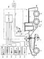
次に、本実施の形態において、走行時における車体振動を抑制する振動抑制機構を図2を用いて説明する。
図2に示されるように、振動抑制機構70Aは、切替弁71aと、アキュムレータ72aと、コントローラ74とを主に有している。
アキュムレータ72aは、1対のリフトシリンダ44、45のうち一方のリフトシリンダ44の油圧回路に接続されている。具体的には、アキュムレータ72aは、リフトシリンダ44のヘッド側回路に接続されている。切替弁71aは、リフトシリンダ44とアキュムレータ72aとの間に接続されている。
メインバルブ73は、油路81aを通じてリフトシリンダ44のヘッド側回路と接続されている。切替弁71aは、油路81aから分岐した油路82aに接続されている。切替弁71aは、たとえばコントローラ74に電気的に接続されている。切替弁71aは、たとえばコントローラ74からの制御信号に基づいて開閉動作をする。
切替弁71aが開いた状態にあるときは、アキュムレータ72aがリフトシリンダ44のヘッド側回路に接続される。また切替弁71aが閉じた状態にあるときは、アキュムレータ72aとリフトシリンダ44のヘッド側回路との接続は遮断される。
本実施の形態のモータグレーダ1は、リフトシリンダ長検出センサ80と、作業機操作部75と、速度センサ76と、速度段検出センサ77と、作業機ロックスイッチ78と、油圧センサ79とを主に有している。リフトシリンダ長検出センサ80、作業機操作部75、速度センサ76、速度段検出センサ77、作業機ロックスイッチ78および油圧センサ79の各々は、コントローラ74に接続されている。
リフトシリンダ長検出センサ80は、1対のリフトシリンダ44、45の各々のシリンダ長を検出するセンサである。このリフトシリンダ長検出センサ80は、たとえば1対のリフトシリンダ44、45の各々に取り付けられたストロークセンサであるが、これに限定されるものではなく近接センサであってもよい。このリフトシリンダ長検出センサ80によって検出された1対のリフトシリンダ44、45の各々のシリンダ長の信号がコントローラ74に入力される。
作業機操作部75は、たとえばオペレータがブレード42を操作するための操作レバーであり、キャブ3内に配置されている。たとえば作業機操作部75におけるレバーの傾倒状態などに応じたPPC(Pressure Proportional Control)圧が圧力センサで検出され、検出された圧力信号がコントローラ74に入力される。
速度センサ76は、モータグレーダ1の走行速度を検出するセンサである。速度センサ76は、たとえば車両トランスミッションに接続され、そのトランスミッションの出力軸の角速度を示す速度信号を出力するものである。速度センサ76によって検出された速度信号がコントローラ74に入力される。
速度段検出センサ77は、変速機チェンジレバーの速度段位置(変速機チェンジレバーが前進の何段に位置するか、後進の何段に位置するか、またはニュートラルに位置するか)を検出するセンサである。速度段検出センサ77によって検出された速度段検出信号がコントローラ74に入力される。
作業機ロックスイッチ78は、作業機操作部75による作業機4の操作を禁止するために操作するスイッチである。作業機ロックスイッチ78がオン状態に操作されると、作業機の操作に用いられる油圧アクチュエータに供給される油圧の制御が制限される。これにより、作業機操作部75が操作されても油圧アクチュエータに供給される油圧が変更されなくなり、作業機4の操作が禁止される。作業機ロックスイッチ78のON・OFF信号がコントローラ74に入力される。
油圧センサ79は、たとえばリフトシリンダ44内の油圧を検出するセンサである。この油圧センサ79によって検出された油圧信号の変動から作業時におけるブレード42の油圧変動と振動とを検出することができる。油圧センサ79によって検出された油圧信号またはその油圧から検出されたブレード42の油圧変動または振動がコントローラ74に入力される。なおブレード42の油圧変動または振動は、コントローラ74に入力された油圧センサ79の油圧信号から算出されてもよい。
コントローラ74は、リフトシリンダ長検出センサ80によって検出された1対のリフトシリンダ44、45の各々のシリンダ長に基づいてドローバ40の高さを算出する。このドローバ40の高さから、ブレード42の高さを知ることができる。このブレード42の高さから、モータグレーダ1が走行中か否かを判別することができる。
具体的には、ブレード42が接地するであろう高さ位置となるドローバ40の高さ位置よりも実際のドローバ40の高さが所定高さだけ高い位置にあれば、モータグレーダ1は作業中ではなく、走行中であると判断することができる。
また1対のリフトシリンダ44、45の各々のシリンダ長に基づいてドローバ40の傾き(ブレード42の傾き)も算出可能である。ドローバ40の高さと、このドローバ40の傾きとに基づいて、モータグレーダ1が走行中か否かの判定がなされてもよい。
コントローラ74は、算出したドローバ40の少なくとも高さに基づいて切替弁71aの開閉を制御する。コントローラ74は、算出したドローバ40の高さおよび傾きに基づいて切替弁71aの開閉を制御してもよい。
またコントローラ74は、リフトシリンダ長検出センサ80によって検出された1対のリフトシリンダ44、45の各々のシリンダ長に基づいて切替弁71aの開閉を制御してもよい。
またコントローラ74は、算出したブレード42の少なくとも高さに基づいて切替弁71aの開閉を制御してもよく、また算出したブレード42の高さおよび傾きに基づいて切替弁71aの開閉を制御してもよい。
またコントローラ74は、上記ドローバ40の高さと他の情報とに基づいて切替弁71aの開閉を制御してもよい。他の情報とは、たとえば(1)作業機操作部75による操作時間、(2)ブレード42の油圧変動および振動の少なくとも一方、(3)モータグレーダ1の走行速度および速度段の少なくとも一方、(4)作業機ロックスイッチのON・OFF信号のうちの1つまたはこれらの任意の組み合わせである。
ドローバ40の高さに上記他の情報を組み合わせることによって、モータグレーダ1が走行中か否かをより正確に判別することが可能となる。たとえばオペレータによる作業機操作部75の操作が所定時間ない場合には、モータグレーダ1は作業中ではなく走行中であると判断することができる。よって作業機操作部75による操作時間に基づいてモータグレーダ1は作業中ではなく走行中であると判断することができる。
またブレード42の油圧変動、振動が作業中に生じる特有の油圧変動、振動であるか否かにより、モータグレーダ1が作業中か走行中かを判断することができる。
またモータグレーダ1の走行速度、速度段からモータグレーダ1が作業中か走行中かを判断することができる。たとえばモータグレーダ1の車速が40km/h以上である場合にはモータグレーダ1は走行中であると判断することができる。またたとえばモータグレーダ1の速度段が前進5段(5速)以上である場合にはモータグレーダ1は走行中であると判断することができる。なおモータグレーダ1が前進8段(8速)まで有する場合には、モータグレーダ1の速度段が8速である場合にはモータグレーダ1は走行中であると判断することができる。
また作業機ロックスイッチからON信号が出力されている場合には、モータグレーダ1は作業中ではなく走行中であると判断することができる。
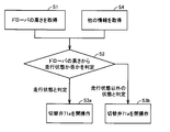
次に、本実施の形態におけるモータグレーダ1の制御方法について図2および図3を用いて説明する。なお図3は、一実施の形態におけるモータグレーダの制御方法を示すフロー図である。
図2に示されるように、まずドローバ40の高さが取得される(ステップS1:図3)。このドローバ40の高さは、たとえば1対のリフトシリンダ44、45のストローク長から取得される。このドローバ40の高さは、1対のリフトシリンダ44、45のストローク長に基づいてコントローラ74にて算出されてもよい。またドローバ40の高さは、たとえば近接スイッチなどによるセンサで取得されてコントローラ74に入力されてもよい。
取得されたドローバ40の高さからモータグレーダ1が走行状態か否かが判定される(ステップS2:図3)。この判定は、たとえばコントローラ74において行われてもよい。
モータグレーダ1が走行状態であると判定された場合、コントローラ74は切替弁71aが開くよう制御する(ステップS3a:図3)。切替弁71aが開くことにより、アキュムレータ72aがリフトシリンダ44のヘッド側回路と接続される。このためブレード42が上下動可能なようにリフトシリンダ44、45を介在して車両本体につり下げられる(懸架される)。この時、アキュムレータ72aのばね効果と、油圧回路の絞りからなる減衰効果とを有する動吸振器が構成され、走行中における車体の振動が抑制される。
モータグレーダ1が走行状態以外の状態であると判定された場合、コントローラ74は切替弁71aが閉じるよう制御する(ステップS3b:図3)。切替弁71aが閉じることにより、アキュムレータ72aとリフトシリンダ44のヘッド側回路との接続が遮断される。このためモータグレーダ1の作業中におけるブレード42の上下動を抑えることができる。
またドローバ40の高さだけでなく、他の情報も加味してモータグレーダ1が走行状態であるか否かが判別されてもよい。この場合には、他の情報も取得される(ステップS4:図3)。他の情報とは、上記のように、たとえば作業機操作部75による操作時間、ブレード42の油圧変動および振動の少なくとも一方、モータグレーダ1の走行速度および速度段の少なくとも一方、作業機ロックスイッチのON・OFF信号、のうちの1つまたはこれらの任意の組み合わせである。
ドローバ40の高さと上記他の情報とに基づいてモータグレーダ1が走行状態か否かを判定することにより(ステップS2:図3)、走行状態か否かの判定の精度を高めることができる。
次に、本実施の形態の作用効果について説明する。
本実施の形態においては、図2に示されるように、車両本体に対するドローバ40の高さに基づいて切替弁71aの開閉が制御される。これにより、上記ドローバ40の高さに基づいて切替弁71aの開閉を自動で行うことができ、オペレータの労力を省略することが可能となる。
本実施の形態においては、図2に示されるように、車両本体に対するドローバ40の高さに基づいて切替弁71aの開閉が制御される。これにより、上記ドローバ40の高さに基づいて切替弁71aの開閉を自動で行うことができ、オペレータの労力を省略することが可能となる。
また本実施の形態においては、図2に示されるように、切替弁71aおよびアキュムレータ72aは、リフトシリンダ44のヘッド側回路に接続されている。これにより切替弁71aが開くことで、アキュムレータ72aがリフトシリンダ44のヘッド側回路と接続される。このためブレード42が上下動可能なようにリフトシリンダ44、45を介在して車両本体につり下げられる(懸架される)。この時、アキュムレータ72aのばね効果と、油圧回路の絞りからなる減衰効果とを有する動吸振器が構成され、走行中の車体の振動が抑制される。
また本実施の形態においては、図2に示されるように、コントローラ74は、ドローバ40の高さと、オペレータによる作業機操作部75の操作時間とに基づいて切替弁71aの開閉を制御する。このようにドローバ40の高さだけでなく、オペレータによる作業機操作部75の操作時間も加味して走行状態か否かの判定を行うことにより、走行状態の判定をより正確に行うことが可能となる。
また本実施の形態においては、図2に示されるように、コントローラ74は、ドローバ40の高さと、ブレード42の油圧変動および振動の少なくとも一方とに基づいて切替弁71aの開閉を制御する。このようにドローバ40の高さだけでなく、ブレード42の油圧変動、振動も加味して走行状態か否かの判定を行うことにより、走行状態の判定をより正確に行うことが可能となる。
また本実施の形態においては、図2に示されるように、コントローラ74は、ドローバ40の高さと、モータグレーダ1の走行速度および速度段の少なくとも一方とに基づいて切替弁71aの開閉を制御する。このようにドローバ40の高さだけでなく、モータグレーダ1の走行速度、速度段も加味して走行状態か否かの判定を行うことにより、走行状態の判定をより正確に行うことが可能となる。
また本実施の形態においては、図2に示されるように、コントローラ74は、ドローバ40の高さと、作業機ロックスイッチ78のON・OFF信号とに基づいて切替弁71aの開閉を制御する。このようにドローバ40の高さだけでなく、作業機ロックスイッチ78のON・OFF信号も加味して走行状態か否かの判定を行うことにより、走行状態の判定をより正確に行うことが可能となる。
(他の実施の形態)
図4は、他の実施の形態におけるモータグレーダの構成を概略的に示す側面図である。
図4は、他の実施の形態におけるモータグレーダの構成を概略的に示す側面図である。
本実施の形態においては、図4に示されるように、作業時の衝撃を抑制する衝撃抑制機構70Bを有している。衝撃抑制機構70Bは、切替弁71b、アキュムレータ72bおよびコントローラ74を有している。
切替弁71bおよびアキュムレータ72bは、リフトシリンダ44のキャップ側回路に接続されている。具体的には、アキュムレータ72bは、1対のリフトシリンダ44、45のうち一方のリフトシリンダ44の油圧回路に接続されている。具体的には、アキュムレータ72bは、リフトシリンダ44のキャップ側回路に接続されている。切替弁71bは、リフトシリンダ44とアキュムレータ72bとの間に接続されている。
メインバルブ73は、油路81bを通じてリフトシリンダ44のキャップ側回路と接続されている。切替弁71bは、油路81bから分岐した油路82bに接続されている。切替弁71bは、たとえばコントローラ74に電気的に接続されている。切替弁71bは、たとえばコントローラ74からの制御信号に基づいて開閉動作をする。
切替弁71bが開いた状態にあるときは、アキュムレータ72bがリフトシリンダ44のキャップ側回路に接続される。また切替弁71bが閉じた状態にあるときは、アキュムレータ72bとリフトシリンダ44のヘッド側回路との接続は遮断される。
なお、上記以外の本実施の形態における構成は、図2に示す実施の形態の構成とほぼ同じであるため、同一の要素については同一の符号を付し、その説明を繰り返さない。
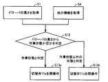
次に、本実施の形態におけるモータグレーダ1の制御方法について図4および図5を用いて説明する。なお図5は、他の実施の形態におけるモータグレーダの制御方法を示すフロー図である。
図4に示されるように、まずドローバ40の高さが取得される(ステップS1:図5)。このドローバ40の高さは、たとえば1対のリフトシリンダ44、45のストローク長から取得される。このドローバ40の高さは、1対のリフトシリンダ44、45のストローク長に基づいてコントローラ74にて算出されてもよい。またドローバ40の高さは、たとえば近接スイッチなどによるセンサで取得されてコントローラ74に入力されてもよい。
取得されたドローバ40の高さからモータグレーダ1が作業状態か否かが判定される(ステップS12:図5)。この判定は、たとえばコントローラ74において行われてもよい。
モータグレーダ1が作業状態であると判定された場合、コントローラ74は切替弁71bが開くよう制御する(ステップS13a:図5)。切替弁71bが開くことにより、アキュムレータ72bがリフトシリンダ44のキャップ側回路と接続される。このためブレード42が作業中に岩などの路面凸部に衝突などして衝撃を受けた場合、アキュムレータ72bの気室(隔膜内の空間)が収縮する。これにより作業中におけるブレード42の衝撃がアキュムレータ72bにより吸収される。
モータグレーダ1が作業状態以外の状態であると判定された場合、コントローラ74は切替弁71bが閉じるよう制御する(ステップS13b:図5)。切替弁71bが閉じることにより、アキュムレータ72bとリフトシリンダ44のキャップ側回路との接続が遮断される。このためモータグレーダ1の走行中におけるブレード42の上下動を抑えることができる。
またドローバ40の高さだけでなく、他の情報も加味してモータグレーダ1が作業状態であるか否かが判別されてもよい。この場合には、他の情報も取得される(ステップS4:図5)。他の情報とは、上記のように、たとえば作業機操作部75による操作時間、ブレード42の油圧変動および振動の少なくとも一方、モータグレーダ1の走行速度および速度段の少なくとも一方、作業機ロックスイッチのON・OFF信号、のうちの1つまたはこれらの任意の組み合わせである。
ドローバ40の高さと上記他の情報とに基づいてモータグレーダ1が作業状態か否かを判定することにより(ステップS2:図5)、作業状態か否かの判定の精度を高めることができる。
次に、本実施の形態の作用効果について説明する。
本実施の形態においては、図4に示されるように、車両本体に対するドローバ40の高さに基づいて切替弁71bの開閉が制御される。これにより、上記ドローバ40の高さに基づいて切替弁71bの開閉を自動で行うことができ、オペレータの労力を省略することが可能となる。
本実施の形態においては、図4に示されるように、車両本体に対するドローバ40の高さに基づいて切替弁71bの開閉が制御される。これにより、上記ドローバ40の高さに基づいて切替弁71bの開閉を自動で行うことができ、オペレータの労力を省略することが可能となる。
また本実施の形態においては、図4に示されるように、切替弁71bおよびアキュムレータ72bは、リフトシリンダ44のキャップ側回路に接続されている。これにより切替弁71bが開くことで、アキュムレータ72bがリフトシリンダ44のキャップ側回路と接続される。このためブレード42が作業中に岩などの路面凸部に衝突などして衝撃を受けた場合、アキュムレータ72bの気室(隔膜内の空間)が収縮する。これにより作業中におけるブレード42の衝撃がアキュムレータ72bにより吸収される。
また本実施の形態においては、図4に示されるように、コントローラ74は、ドローバ40の高さと、オペレータによる作業機操作部75の操作時間とに基づいて切替弁71bの開閉を制御する。このようにドローバ40の高さだけでなく、オペレータによる作業機操作部75の操作時間も加味して作業状態か否かの判定を行うことにより、作業状態の判定をより正確に行うことが可能となる。
また本実施の形態においては、図4に示されるように、コントローラ74は、ドローバ40の高さと、ブレード42の油圧変動および振動の少なくとも一方とに基づいて切替弁71bの開閉を制御する。このようにドローバ40の高さだけでなく、ブレード42の油圧変動、振動も加味して作業状態か否かの判定を行うことにより、作業状態の判定をより正確に行うことが可能となる。
また本実施の形態においては、図4に示されるように、コントローラ74は、ドローバ40の高さと、モータグレーダ1の走行速度および速度段の少なくとも一方とに基づいて切替弁71bの開閉を制御する。このようにドローバ40の高さだけでなく、モータグレーダ1の走行速度、速度段も加味して作業状態か否かの判定を行うことにより、作業状態の判定をより正確に行うことが可能となる。
また本実施の形態においては、図4に示されるように、コントローラ74は、ドローバ40の高さと、作業機ロックスイッチ78のON・OFF信号とに基づいて切替弁71bの開閉を制御する。このようにドローバ40の高さだけでなく、作業機ロックスイッチ78のON・OFF信号も加味して作業状態か否かの判定を行うことにより、作業状態の判定をより正確に行うことが可能となる。
上記2つの実施の形態においては、1対のリフトシリンダ44、45のうち一方のリフトシリンダ44に切替弁71a(または切替弁71b)とアキュムレータ72a(またはアキュムレータ72b)とが設けられた構成について説明したが、切替弁71a(または切替弁71b)とアキュムレータ72a(またはアキュムレータ72b)とはリフトシリンダ45に設けられていてもよく、また1対のリフトシリンダ44、45のそれぞれに設けられていてもよい。
今回開示された実施の形態はすべての点で例示であって制限的なものではないと考えられるべきである。本発明の範囲は上記した説明ではなくて請求の範囲によって示され、請求の範囲と均等の意味および範囲内でのすべての変更が含まれることが意図される。
1 モータグレーダ、2 車体フレーム、2F 前端、2R 後端、3 キャブ、4 作業機、6 エンジン室、7 ステアリングシリンダ、11 前輪、12 後輪、21 リアフレーム、22 フロントフレーム、23 アーティキュレートシリンダ、40 ドローバ、41 旋回サークル、42 ブレード、44,45 リフトシリンダ、51 カウンタウェイト、70A 振動抑制機構、70B 衝撃抑制機構、71a,71b 切替弁、72a,72b アキュムレータ、73 メインバルブ、74 コントローラ、75 作業機操作部、76 速度センサ、77 速度段検出センサ、78 作業機ロックスイッチ、79 油圧センサ、80 リフトシリンダ長検出センサ、81a,81b,82a,82b 油路。
Claims (8)
- 車両本体と、
ブレードを有する作業機と、
前記車両本体に対して前記作業機をつり下げ、かつ前記車両本体に対する前記作業機の高さを変更するシリンダと、
前記シリンダの油圧回路に接続されたアキュムレータと、
前記シリンダと前記アキュムレータとの間に接続された切替弁と、
前記車両本体に対する前記作業機の高さに基づいて前記切替弁の開閉を制御するコントローラとを備えた、モータグレーダ。 - 前記作業機は、前記車両本体に支持され、かつ前記ブレードを支持するドローバを有する、請求項1に記載のモータグレーダ。
- 前記作業機は、前記モータグレーダの進行方向に沿った軸を中心に揺動可能に前記車両本体につり下げられている、請求項1に記載のモータグレーダ。
- 前記切替弁および前記アキュムレータは、前記シリンダのヘッド側回路に接続されている、請求項1に記載のモータグレーダ。
- 作業機操作部をさらに備え、
前記コントローラは、前記作業機の高さと、オペレータによる前記作業機操作部の操作時間とに基づいて前記切替弁の開閉を制御する、請求項1に記載のモータグレーダ。 - 前記コントローラは、前記作業機の高さと、前記ブレードの油圧変動および振動の少なくとも一方とに基づいて前記切替弁の開閉を制御する、請求項1に記載のモータグレーダ。
- 前記コントローラは、前記作業機の高さと、前記モータグレーダの走行速度および速度段の少なくとも一方とに基づいて前記切替弁の開閉を制御する、請求項1に記載のモータグレーダ。
- オペレータによる前記ブレードの操作を禁止する作業機ロックスイッチをさらに備え、
前記コントローラは、前記作業機の高さと、前記作業機ロックスイッチのON・OFF信号とに基づいて前記切替弁の開閉を制御する、請求項1に記載のモータグレーダ。
Applications Claiming Priority (2)
| Application Number | Priority Date | Filing Date | Title |
|---|---|---|---|
| JP2017-119259 | 2017-06-19 | ||
| JP2017119259A JP2019002233A (ja) | 2017-06-19 | 2017-06-19 | モータグレーダ |
Publications (1)
| Publication Number | Publication Date |
|---|---|
| WO2018235523A1 true WO2018235523A1 (ja) | 2018-12-27 |
Family
ID=64735738
Family Applications (1)
| Application Number | Title | Priority Date | Filing Date |
|---|---|---|---|
| PCT/JP2018/020126 Ceased WO2018235523A1 (ja) | 2017-06-19 | 2018-05-25 | モータグレーダ |
Country Status (2)
| Country | Link |
|---|---|
| JP (1) | JP2019002233A (ja) |
| WO (1) | WO2018235523A1 (ja) |
Families Citing this family (2)
| Publication number | Priority date | Publication date | Assignee | Title |
|---|---|---|---|---|
| JP7504012B2 (ja) | 2020-12-10 | 2024-06-21 | 株式会社小松製作所 | 作業機械、作業機械の制御装置、および作業機械の制御方法 |
| JP2024036857A (ja) * | 2022-09-06 | 2024-03-18 | 株式会社小松製作所 | 作業機械、及び、作業機械を制御するための方法 |
Citations (2)
| Publication number | Priority date | Publication date | Assignee | Title |
|---|---|---|---|---|
| JPS63185849U (ja) * | 1987-05-19 | 1988-11-29 | ||
| JPH05339959A (ja) * | 1992-06-05 | 1993-12-21 | Kensetsusho Tohoku Chiho Kensetsu Kyokucho | モータグレーダの振動抑制装置 |
Family Cites Families (3)
| Publication number | Priority date | Publication date | Assignee | Title |
|---|---|---|---|---|
| JPH0633011Y2 (ja) * | 1989-04-07 | 1994-08-31 | 三菱重工業株式会社 | モータグレーダの振動抑制兼衝撃緩衝装置 |
| JP4669499B2 (ja) * | 2007-08-10 | 2011-04-13 | 日本中央競馬会 | ブレード制御装置 |
| US8869908B2 (en) * | 2012-05-07 | 2014-10-28 | Caterpillar Inc. | Anti-bounce control system for a machine |
-
2017
- 2017-06-19 JP JP2017119259A patent/JP2019002233A/ja active Pending
-
2018
- 2018-05-25 WO PCT/JP2018/020126 patent/WO2018235523A1/ja not_active Ceased
Patent Citations (2)
| Publication number | Priority date | Publication date | Assignee | Title |
|---|---|---|---|---|
| JPS63185849U (ja) * | 1987-05-19 | 1988-11-29 | ||
| JPH05339959A (ja) * | 1992-06-05 | 1993-12-21 | Kensetsusho Tohoku Chiho Kensetsu Kyokucho | モータグレーダの振動抑制装置 |
Also Published As
| Publication number | Publication date |
|---|---|
| JP2019002233A (ja) | 2019-01-10 |
Similar Documents
| Publication | Publication Date | Title |
|---|---|---|
| EP1559837B1 (en) | Skid steer loader | |
| JP5064880B2 (ja) | キャブを搭載したモータグレーダ | |
| JP5851037B2 (ja) | 作業機械 | |
| WO2009157230A1 (ja) | ローダ作業機 | |
| WO2018147096A1 (ja) | 作業車両および作業車両の制御方法 | |
| WO2019146206A1 (ja) | 作業機、作業機の制御方法、プログラム及びその記録媒体 | |
| JP7412932B2 (ja) | 作業車両および作業車両の制御方法 | |
| JP2019002233A (ja) | モータグレーダ | |
| JP2018204409A (ja) | 作業車両 | |
| JPH05195554A (ja) | 土工機における油圧アクチュエータ制御装置 | |
| CN112236563A (zh) | 作业机械及机动平路机 | |
| WO2018159210A1 (ja) | 建設機械 | |
| JP2021147807A (ja) | 作業車両および制御方法 | |
| JP3455868B2 (ja) | 建設車両の座席制振装置 | |
| JP3789223B2 (ja) | フロントローダの高さ検出構成 | |
| JP7481089B2 (ja) | 作業車両 | |
| JP7154814B2 (ja) | 作業機械およびその制御方法 | |
| JP2020165093A (ja) | 作業機械用カッティングエッジ、作業機械用ブレードおよび作業機械 | |
| US20250305238A1 (en) | Work machine and method for controlling work machine | |
| JP6026143B2 (ja) | 旋回作業機 | |
| WO2024190473A1 (ja) | 作業機械および作業機械の制御方法 | |
| JP2010059683A (ja) | ローダ作業機 | |
| JP2010059684A (ja) | ローダ作業機 | |
| JP2005170330A (ja) | トラクタのクローラ装置 | |
| JP4443358B2 (ja) | 建設機械 |
Legal Events
| Date | Code | Title | Description |
|---|---|---|---|
| 121 | Ep: the epo has been informed by wipo that ep was designated in this application |
Ref document number: 18820624 Country of ref document: EP Kind code of ref document: A1 |
|
| NENP | Non-entry into the national phase |
Ref country code: DE |
|
| 122 | Ep: pct application non-entry in european phase |
Ref document number: 18820624 Country of ref document: EP Kind code of ref document: A1 |