WO2018235368A1 - 絶縁電線およびワイヤーハーネス - Google Patents
絶縁電線およびワイヤーハーネス Download PDFInfo
- Publication number
- WO2018235368A1 WO2018235368A1 PCT/JP2018/011646 JP2018011646W WO2018235368A1 WO 2018235368 A1 WO2018235368 A1 WO 2018235368A1 JP 2018011646 W JP2018011646 W JP 2018011646W WO 2018235368 A1 WO2018235368 A1 WO 2018235368A1
- Authority
- WO
- WIPO (PCT)
- Prior art keywords
- wire
- insulated wire
- resin composition
- thermoplastic polyurethane
- polyurethane elastomer
- Prior art date
- Legal status (The legal status is an assumption and is not a legal conclusion. Google has not performed a legal analysis and makes no representation as to the accuracy of the status listed.)
- Ceased
Links
Images

Classifications
-
- H—ELECTRICITY
- H01—ELECTRIC ELEMENTS
- H01B—CABLES; CONDUCTORS; INSULATORS; SELECTION OF MATERIALS FOR THEIR CONDUCTIVE, INSULATING OR DIELECTRIC PROPERTIES
- H01B3/00—Insulators or insulating bodies characterised by the insulating materials; Selection of materials for their insulating or dielectric properties
- H01B3/18—Insulators or insulating bodies characterised by the insulating materials; Selection of materials for their insulating or dielectric properties mainly consisting of organic substances
- H01B3/30—Insulators or insulating bodies characterised by the insulating materials; Selection of materials for their insulating or dielectric properties mainly consisting of organic substances plastics; resins; waxes
- H01B3/302—Polyurethanes or polythiourethanes; Polyurea or polythiourea
-
- H—ELECTRICITY
- H01—ELECTRIC ELEMENTS
- H01B—CABLES; CONDUCTORS; INSULATORS; SELECTION OF MATERIALS FOR THEIR CONDUCTIVE, INSULATING OR DIELECTRIC PROPERTIES
- H01B3/00—Insulators or insulating bodies characterised by the insulating materials; Selection of materials for their insulating or dielectric properties
- H01B3/18—Insulators or insulating bodies characterised by the insulating materials; Selection of materials for their insulating or dielectric properties mainly consisting of organic substances
- H01B3/30—Insulators or insulating bodies characterised by the insulating materials; Selection of materials for their insulating or dielectric properties mainly consisting of organic substances plastics; resins; waxes
-
- H—ELECTRICITY
- H01—ELECTRIC ELEMENTS
- H01B—CABLES; CONDUCTORS; INSULATORS; SELECTION OF MATERIALS FOR THEIR CONDUCTIVE, INSULATING OR DIELECTRIC PROPERTIES
- H01B7/00—Insulated conductors or cables characterised by their form
- H01B7/02—Disposition of insulation
- H01B7/0275—Disposition of insulation comprising one or more extruded layers of insulation
-
- H—ELECTRICITY
- H01—ELECTRIC ELEMENTS
- H01B—CABLES; CONDUCTORS; INSULATORS; SELECTION OF MATERIALS FOR THEIR CONDUCTIVE, INSULATING OR DIELECTRIC PROPERTIES
- H01B7/00—Insulated conductors or cables characterised by their form
- H01B7/0045—Cable-harnesses
Definitions
- the present invention relates to an insulated wire and a wire harness, and more particularly to an insulated wire which can be suitably used for electrical connection of a car or the like, and a wire harness including such an insulated wire.
- insulated wire In the insulated wire, it is often required to have high flexibility from the viewpoint of securing the routeability.
- insulated wires used for electrical connection in automobiles being disposed in a limited space or being routed by a complicated route along with recent advancements in functionality and performance of automobiles.
- the demand for flexibility is growing.
- Thinning the insulation coating also contributes to space saving by reducing the diameter of the insulated wire.
- the thickness of the insulating coating is reduced, it is difficult to ensure the wear resistance of the insulating coating.
- Patent Document 2 the abrasion resistance and the like are improved by incorporating a polyester elastomer and a methyl methacrylate-butadiene-styrene resin into a wire covering material obtained by adding a plasticizer to PVC.
- the effect of improving the abrasion resistance by adding these resin components to the PVC resin is limited, and even if the abrasion resistance can be improved, the flexibility of the insulation coating is sufficiently ensured. It is difficult to make it compatible with the wear resistance.
- a method of thinning the insulating coating is used, and the thinning of the insulating coating is performed by reducing the diameter of the insulated wire.
- the thickness of the insulation coating is reduced, it will be difficult to ensure the wear resistance of the insulation coating. Therefore, even when the thickness of the insulating coating is reduced, from the viewpoint of securing sufficient wear resistance, a material having high wear resistance is required as a characteristic of the resin composition itself that constitutes the insulating coating.
- An object of the present invention is to provide an insulated wire provided with an insulating coating made of a resin composition having high wear resistance, and a wire harness provided with such an insulated wire.
- the insulated wire according to the present invention has a wire conductor and an insulation coating for covering the outer periphery of the wire conductor, and the insulation coating is a resin having a thermoplastic polyurethane elastomer as a main component. It consists of a composition.
- the thickness of the insulating coating may be less than 0.7 mm.
- the tensile energy at break of the resin composition is preferably 200 mJ / mm 3 or more.
- the hardness of the thermoplastic polyurethane elastomer may be 85 or more in JIS A hardness.
- the thermoplastic polyurethane elastomer may be an ether-based thermoplastic polyurethane elastomer.
- the conductor cross-sectional area of the wire conductor may be 3 mm 2 or more and 20 mm 2 or less.
- a wire harness according to the present invention includes the above-described insulated wire.
- the insulating coating is composed of a resin composition containing a thermoplastic polyurethane elastomer as a main component.
- the insulation coating has high wear resistance as a material property.
- the thermoplastic polyurethane elastomer is also excellent in the flexibility as the material itself, which also contributes to the balance between the abrasion resistance and the flexibility in the insulation coating.
- the thickness of the insulation coating is less than 0.7 mm, the thinness of the insulation coating makes the insulated wire have high flexibility. In addition, it is easy to achieve reduction in diameter of the insulated wire. And, even if the insulating coating is made thin in this way, sufficient abrasion resistance can be easily compatible with the flexibility because of the effect that the resin composition constituting the insulating coating contains the thermoplastic polyurethane elastomer as the main component.
- the magnitude of the tensile breaking energy serves as a good indicator of the abrasion resistance of the resin composition. It is easy to achieve high abrasion resistance in the coating.
- thermoplastic polyurethane elastomer When the hardness of the thermoplastic polyurethane elastomer is JIS A hardness and is 85 or more, the abrasion resistance of the insulating coating can be particularly easily enhanced.
- thermoplastic polyurethane elastomer is an ether-based thermoplastic polyurethane elastomer
- the thermoplastic polyurethane elastomer tends to be one that provides particularly high abrasion resistance.
- the cross-sectional area of the conductor of the wire conductor is 3 mm 2 or more and 20 mm 2 or less, when thinning the insulation coating using the high wear resistance of the resin composition, the thin diameter of the insulated wire by thinning It is possible to obtain both of the effects of conversion and the effects of flexibility improvement.
- the wire harness concerning the said invention is easy to ensure abrasion resistance even if it thins the insulation coating of an insulated wire by including the above insulated wires. By thinning the insulation coating and improving the flexibility and reducing the diameter of the insulated wire, it also leads to the improvement of the flexibility of the wire harness as a whole and space saving.
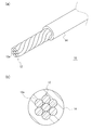
- the outline of the insulated wire concerning one Embodiment of this invention is shown.
- the insulated wire 10 includes a wire conductor 12 and an insulating coating 14 that covers the outer periphery of the wire conductor 12.
- the insulated wire 10 can be obtained by extrusion-coating the resin composition to be the insulation coating 14 on the outer periphery of the wire conductor 12.
- the insulating coating 14 is made of a resin composition containing a thermoplastic polyurethane elastomer as a main component, as will be described in detail later.
- the insulation coating 14 has high abrasion resistance by being made of such a resin composition. Even when the thickness of the insulating coating 14 is reduced for the purpose of improving the flexibility and reducing the diameter of the insulated wire 10 by forming the insulating coating 14 of a resin composition having high wear resistance, the resistance of the insulating coating 14 is resistant to Wearability can be secured.
- the thickness of the insulating coating 14 is preferably less than 0.7 mm. Thereby, in the insulated wire 10, it is easy to achieve improvement in flexibility and diameter reduction.
- the thickness of the insulating coating 14 is more preferably 0.5 mm or less.
- the thickness of the insulating coating 14 is preferably 0.3 mm or more from the viewpoint of easily securing the mechanical properties of the insulating coating 14 including the wear resistance.
- the average thickness may be in the above range.
- wire conductor 12 metal materials such as aluminum and magnesium can also be used other than copper. These metallic materials may be alloys. Other metallic materials for alloying include iron, nickel, magnesium, silicon, combinations thereof, and the like.
- the conductivity is lower than that of copper or copper alloy generally used as a wire conductor, so if it is intended to ensure the necessary conductivity, the wire conductor
- the outer diameter of 12 tends to be large. Therefore, by enabling the insulating coating 14 to be formed thin using a material with high wear resistance, the significance of reducing the diameter of the entire insulated wire 10 is particularly increased.
- the wire conductor 12 may be formed of a single wire or may be formed of a stranded wire formed by twisting a plurality of strands 12a. From the viewpoint of securing the flexibility of the insulated wire 10, the wire conductor 12 is preferably made of a stranded wire. In this case, when the outer diameter of the strands 12a constituting the stranded wire is 0.45 mm or less, it is easy to particularly secure the flexibility of the entire stranded wire.
- the conductor cross-sectional area of the wire conductor 12 is not particularly specified, but is preferably 3 mm 2 or more. If the conductor cross-sectional area is less than 3 mm 2 , even if the thickness of the insulating coating 14 is reduced, the effect of reducing the diameter of the entire insulated wire 10 is relatively poor, but the conductor cross-sectional area is 3 mm 2 or more For example, reduction in diameter by thinning the insulation coating 14 is effectively achieved. Insulated wires having a conductor cross-sectional area of 3 mm 2 or more are generally referred to as heavyweights, and in the case where an insulation coating is formed using a conventional general PVC resin, wear resistance is ensured. In order to do this, the thickness of the insulation coating is usually 0.8 mm or more.
- the conductor cross-sectional area of the wire conductor 12 may be 8 mm 2 or more.
- the conductor cross-sectional area of the wire conductor 12 is preferably 20 mm 2 or less. If the conductor cross-sectional area exceeds 20 mm 2 , the flexibility of the wire conductor 12 itself becomes too low, and sufficient flexibility as the entire insulated wire 10 is ensured even if the flexibility of the insulating coating 14 is enhanced by thinning. If the conductor cross-sectional area is 20 mm 2 or less, it is possible to effectively achieve the improvement of the flexibility of the insulated wire 10 by thinning the insulating coating 14. More preferably, the conductor cross-sectional area of the wire conductor 12 may be 16 mm 2 or less.
- the thickness of the insulation coating 14 and the conductor cross-sectional area of the wire conductor 12 any combination may be selected, and as the insulation coating 14 is thinner and as the conductor cross-sectional area of the wire conductor 12 is smaller, Can increase the flexibility of However, the smallness of the thinness and the conductor cross-sectional area of the insulating coating 14 from the viewpoint of both effectively contribute to the improvement of the flexibility of the entire insulated wire 10, the conductor cross-sectional area, 3 mm 2, etc., when it is 8 mm 2 or less Preferably, the thickness of the insulating coating 14 is 0.4 mm or less. On the other hand, the conductor cross-sectional area, 20 mm 2, etc., if exceeded 8 mm 2, is preferably less than 0.7mm thickness of the insulating coating 14.
- the use of the insulated wire 10 according to the present embodiment is not particularly limited, but it can be used as various wires for automobiles, equipment, information communication, electric power, ships, aircraft, and the like. In particular, it can be suitably used as a wire for automobiles.
- a degree of freedom in handling is required from the viewpoint of space saving and the like, and high flexibility is required.
- the wire diameter reduction is also required.
- the demand for flexibility is large.
- the insulating coating 14 is made of a resin composition having high wear resistance, the insulating coating 14 is thinned while maintaining sufficient wear resistance, and flexibility and wear resistance are achieved. It is possible to make the properties compatible and to make the diameter of the insulated wire 10 smaller.
- the insulated wire 10 according to the present embodiment may be used in the form of a single wire or in the form of a wire harness including a plurality of insulated wires. Even if all the insulated wires constituting the wire harness are made of the insulated wire 10 according to the present embodiment, a part of the insulated wires 10 may be formed of the insulated wire 10 according to the present embodiment.
- the insulation coating 14 is thinned while securing wear resistance, and the diameter and diameter of the insulated wire 10 are reduced, whereby the entire wire harness including the insulated wire 10 is obtained. It can also contribute to the improvement of flexibility and space saving.
- the resin composition that constitutes the insulating coating 14 is mainly composed of a thermoplastic polyurethane elastomer.
- having the thermoplastic polyurethane elastomer as the main component means that the content of the thermoplastic polyurethane elastomer is the largest among the polymer components constituting the resin composition.
- the thermoplastic polyurethane elastomer preferably accounts for 50% by mass or more of the polymer component, and more preferably 80% by mass or more. It is particularly preferred that the polymeric component consists only of the thermoplastic polyurethane elastomer.
- Thermoplastic polyurethane elastomers have hard segments and soft segments in the molecular structure, and the hard segments are composed of polyurethane units.
- the type of soft segment is not particularly limited, and an ether-based thermoplastic polyurethane elastomer in which the soft segment has a polyether structure, an ester-based thermoplastic polyurethane elastomer in which a soft segment has a polyester structure, a polycarbonate A carbonate-based thermoplastic polyurethane elastomer having a system structure can be exemplified.
- the thermoplastic polyurethane elastomer contained in the resin composition may consist of only a single type or a mixture of a plurality of types.
- the thermoplastic polyurethane elastomer is a material having excellent abrasion resistance
- the resin composition constituting the insulation coating 14 contains the thermoplastic polyurethane elastomer as a main component, so that the resin composition has high resistance to material properties. Abrasive.
- the thermoplastic polyurethane elastomer is excellent in wear resistance and flexibility, the effect of the characteristics of the material itself is combined with the effect of thinning the insulation coating 14 to improve the flexibility of the insulated wire 10. It can contribute.
- the thermoplastic polyurethane elastomer is preferably an ether-based thermoplastic polyurethane elastomer among those listed above.
- the hardness of the thermoplastic polyurethane elastomer is preferably 85 or more in JIS A hardness.
- the thermoplastic polyurethane elastomer having such hardness makes the insulation coating 14 have particularly excellent abrasion resistance. It is presumed that this is because the thermoplastic polyurethane elastomer has high hardness, and the surface of the insulating coating 14 is less susceptible to damage such as scratches and cracks due to contact or friction with other members.
- the hardness of the thermoplastic polyurethane elastomer is 90 or more in JIS A hardness. Not only the state of the thermoplastic polyurethane elastomer alone but also the entire resin composition constituting the insulating coating 14 preferably has a hardness of 85 or more, or 90 or more in JIS A hardness.
- the resin composition constituting the insulation coating 14 may appropriately contain components other than the thermoplastic polyurethane elastomer as long as the abrasion resistance of the thermoplastic polyurethane elastomer is not significantly impaired.
- Components other than thermoplastic polyurethane elastomers include other polymeric components and additives.
- thermoplastic polyurethane elastomers in particular, maleic acid modified styrene ⁇ ethylene ⁇ butylene ⁇ styrene block copolymer (SEBS), amine modified SEBS, etc., styrenic thermoplastic elastomer ⁇ oxazoline modified polystyrene (PS)
- the additive that can be contained in the resin composition is also not particularly limited, and an additive, such as an antioxidant and a flame retardant, that can be usually contained in the resin composition for wire covering can be appropriately contained.
- an additive such as an antioxidant and a flame retardant, that can be usually contained in the resin composition for wire covering
- the following can be exemplified as additives expected to have the effect of improving the wear resistance.
- Carbodiimide group-containing compounds preferably 5 parts by mass or less per 100 parts by mass of the thermoplastic polyurethane elastomer
- -Inorganic filler such as calcium carbonate, talc, clay, silica etc.
- a plasticizer may be added to the resin composition.
- the addition of the plasticizer has the effect of improving the flexibility of the thermoplastic polyurethane elastomer to some extent, the abrasion resistance is likely to be greatly reduced, so from the viewpoint of maintaining the abrasion resistance, the plasticizer is not added. Is preferred.
- the resin composition which comprises the insulation coating 14 has the tensile breaking energy of 200 mJ / mm ⁇ 3 > or more.
- the tensile breaking energy of the resin composition is a good index for evaluating the wear resistance
- the resin composition has a tensile breaking energy of 200 mJ / mm 3 or more
- the insulating coating 14 is thinned. Also, it is easy to ensure high wear resistance.
- Tensile energy to break of the resin composition 250 mJ / mm 3 or more, further, 400 mJ / mm 3 or more, and when is 550 mJ / mm 3 or more, more preferably.
- thermoplastic polyurethane elastomer alone is a major component, 200 mJ / mm 3 or more, also 250 mJ / mm 3 or more, 400 mJ / mm 3 or more, 550 mJ / mm 3 or more tensile energy to break It is preferable to have
- the tensile breaking energy of the resin composition has a high correlation with the abrasion resistance, and the resin composition having a large tensile breaking energy can be regarded as having high abrasion resistance.
- the tensile energy to break directly indicates the magnitude of energy given to the material until it breaks when the material is pulled.
- the tensile breaking energy of the resin composition can be evaluated, for example, by a tensile test in accordance with JIS K 7161.
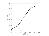
- the chuck is held at two places along the length direction of the sample made of the resin composition, and a load for pulling the sample is applied between the chucks. At this time, the relationship between the applied load (stress, unit: MPa) and the elongation (strain, unit: dimensionless) per unit area until the sample breaks is recorded. Then, as illustrated in FIG.
- an SS curve stress-strain curve
- the area under the SS curve (the area of the area surrounded by the SS curve, the horizontal axis, and the vertical line passing through the break point) until the time of breakage is calculated, and the obtained value is used as the resin material.
- tensile breaking energy (unit: mJ / mm 3 ) of
- the tensile energy to break directly indicates the strength of the material against tension and is not generally used as an indicator of wear resistance. However, as shown in the following examples, there is a positive correlation between tensile energy to break and wear resistance, and tensile energy to break can be used as an indicator of wear resistance. It is considered that this is because the tensile energy to break has a phase between the energy consumed when scraping the resin material on the surface of the insulated wire 10 and the phase.
- the abrasion resistance can also be evaluated directly by an abrasion test in which a stimulus such as friction is applied to an actual sample and the degree of abrasion is observed. However, instead of that, or in addition to that, measurement of tensile energy at break by tensile test is performed, and the index of wear resistance is used to evaluate the wear resistance of resin materials more simply and accurately. It can be predicted.
- elongation at break tensile breaking elongation
- applied load tensile breaking strength
- tensile modulus gradient of rising portion of SS curve
- the resin composition mainly composed of the above-mentioned thermoplastic polyurethane elastomer but also the high abrasion resistance as the insulation coating 14 of the insulated wire 10 by utilizing the correlation between the tensile energy at break and the abrasion resistance
- the resin composition can be identified. That is, when it is intended to obtain the insulating coating 14 made of a material having high wear resistance for the purpose of thinning the insulating coating 14 in the insulated wire 10 etc., the tensile breaking energy which gives the desired wear resistance
- the threshold value of may be set, and a resin composition having a tensile breaking energy equal to or higher than the threshold value may be used.
- the relationship between tensile energy at break and wear resistance is greater than the type of resin composition (the type of polymer material as the main component), and has a single correlation function (linear or curved) Therefore, if a resin composition having a tensile energy at break equal to or higher than a predetermined threshold value is used, the insulating coating 14 having a desired high abrasion resistance can be obtained regardless of the details of the component composition of the resin composition. It becomes possible.
- a specific threshold value of tensile energy to break may be appropriately selected according to the desired degree of wear resistance.
- the insulation resistance 14 as a whole is maintained while maintaining the same level of wear resistance as compared with the insulation coating made of conventional PVC resin.
- a demand is expected to reduce the thickness of the coating 14.
- the wear resistance of the entire insulation coating 14 increases as the thickness of the insulation coating 14 increases. Therefore, in order to achieve the same level of wear resistance in the insulation coating 14 having a smaller thickness than the conventional one, the material properties (thickness The tensile energy to break, which indicates the wear resistance as a characteristic of the material itself) can be made higher than before.
- Test A Properties of Insulation Coating Mainly Composed of Thermoplastic Polyurethane Elastomer
- Test method (1) Preparation of sample Aluminum stranded wire of conductor cross-sectional area 3 mm 2 (wire diameter 0.32 mm, wire number 37) and conductor cross-sectional area 20 mm 2 (wire diameter 0.32 mm, wire number 19/13) I prepared a conductor.
- the resin composition which consists of a component shown to Table 1, 2 was extrusion-molded by predetermined thickness on the outer periphery of each twisted wire
- each thermoplastic polyurethane elastomer was used as it was as a resin composition
- each component was knead
- the content of each component is shown in units of parts by mass.
- TPU 1 (ether: JIS A hardness 88): Dainichi Seika Co., Ltd. product "Resamine P-2288” TPU 2 (ether: JIS A hardness 83): Dainichi Seika Co., Ltd. "Resamin P-2283" ⁇ TPU 3 (ester type; JIS A hardness 91): Dainichi Seika Co., Ltd. product "Resamine P-1078” TPU 4 (ester type; JIS A hardness 80): BASF Corporation "Elastlan S80A” -TPU 5 (carbonate type; JIS A hardness 83): Dainichi Seika Co., Ltd.
- the tape abrasion test based on ISO6722 evaluated the abrasion resistance. That is, the tape-like sandpaper was pressed with a load of 1500 g on the outer circumference of the insulated wire according to each example and comparative example, and the moving distance of the tape until the wire conductor was exposed was measured. The larger the movement distance, the better the wear resistance, and for a sample with a conductor cross-sectional area of 3 mm 2 , the movement resistance is "A" which is excellent in wear resistance if the movement distance is 400 mm or more. The abrasion resistance was determined to be "B", and if less than 200 mm, the abrasion resistance was determined to be "C".
- each insulated wire cut out into a length of 400 mm was fixed at a position of 75 mm from both ends so that the bending radius was 90 mm. And in the middle position of those fixing parts, 50 mm / min. Vertical bending at a speed of At this time, the bending radius is set to 22.5 mm for a sample having a conductor cross-sectional area of 3 mm 2 , and 45 mm for a sample having a conductor cross-sectional area of 20 mm 2 . And the repulsive force at the time of adding a bending was measured by the load cell.
- the sample having a conductor cross-sectional area of 20 mm 2 was evaluated as “A” with high flexibility if the repulsive force is less than 10 N, and “B” with low flexibility if it is 10 N or more.
- Tables 1 and 2 show the measured values of tensile energy to break, wear resistance, and flexibility and the evaluation results as well as the configuration of the insulated wire for each example and each comparative example.
- the flexibility of the insulated wire depends on the thickness of the insulation coating, and in Examples A1 to A7 in which the thickness of the insulation coating is less than 0.7 mm, high flexibility is achieved.
- the flexibility of the insulated wire does not show a large dependence on the conductor cross section.
- Test B Relationship between tensile energy at break and wear resistance of insulating coating
- Test method (1) Preparation of sample It carried out similarly to the said test A, and produced the insulated wire.
- the conductor cross-sectional area is 3 mm 2
- the thickness of the insulating coating is 0.7 mm.
- polyester elastomer 1 Hytrel 4777 manufactured by Toray DuPont Co., Ltd.
- -Polyester elastomer 2 "Hytrel 7277” manufactured by Toray DuPont Co., Ltd.
- Polyolefin elastomer "Thermlan QT60MB” manufactured by Mitsubishi Chemical Corporation -Modified polyphenylene ether (PPE): “Zylon AF700” manufactured by Asahi Kasei Corporation -Polyacetal (POM): Asahi Kasei Co., Ltd. "tenac EX 352"
- FIG. 2 shows an SS curve obtained for the sample of Example B2 as an example.
- Table 3 shows the evaluation results of the tensile modulus of elasticity, the tensile energy at break, and the wear resistance as well as the resin type of the insulation coating for each sample. Further, FIG. 3 shows a plot of the relationship between the tensile energy at break and the result of the wear resistance evaluation.
- the tensile energy to break shows a large value of 200 mJ / mm 3 or more. And corresponding to that, the evaluation result of abrasion resistance has become a big value over 1500 mm.
- Table 3 also shows the tensile modulus of each resin type. It is clear that, unlike the tensile energy to break, the tensile modulus does not have a clear correlation with the abrasion resistance.
Landscapes
- Physics & Mathematics (AREA)
- Spectroscopy & Molecular Physics (AREA)
- Organic Insulating Materials (AREA)
- Insulated Conductors (AREA)
- Compositions Of Macromolecular Compounds (AREA)
Abstract
高い耐摩耗性を有する樹脂組成物よりなる絶縁被覆を備えた絶縁電線、およびそのような絶縁電線を備えたワイヤーハーネスを提供する。 電線導体12と、電線導体12の外周を被覆する絶縁被覆14と、を有し、絶縁被覆14が、熱可塑性ポリウレタンエラストマーを主成分とする樹脂組成物よりなる絶縁電線10とする。また、そのような絶縁電線10を含むワイヤーハーネスとする。絶縁被覆14の厚さは、0.7mm未満であるとよい。
Description
本発明は、絶縁電線およびワイヤーハーネスに関し、さらに詳しくは、自動車等の電気接続に好適に用いることができる絶縁電線、およびそのような絶縁電線を含むワイヤーハーネスに関する。
絶縁電線においては、配策性を確保する観点から、高い柔軟性を有することが、しばしば求められる。特に、自動車内の電気接続に用いられる絶縁電線においては、近年の自動車の高機能化および高性能化に伴い、限られた空間に配策されることや、複雑な経路で取り回されることも増えており、柔軟性に対する要求が大きくなっている。
絶縁電線の柔軟性を高める手段として、絶縁被覆を薄くするという方法が取られる場合がある。絶縁被覆を薄くすることは、絶縁電線の細径化による省スペース化にも寄与する。しかし、絶縁被覆を薄くすると、絶縁被覆の耐摩耗性を確保することが難しくなる。自動車内のように、頻繁に振動や他の部材との接触に晒される過酷な環境で絶縁電線を使用する際には、絶縁被覆が高い耐摩耗性を有することが特に重要である。
絶縁電線の柔軟性を高める別の手段として、絶縁被覆を構成する樹脂組成物として柔軟性の高いものを選択するという方法も用いられる。しかし、多くの樹脂材料において、柔軟性を高めるべく成分組成を設定すると、十分な耐摩耗性を確保できないことが多い。
従来一般に、自動車用電線の絶縁被覆材としては、ポリ塩化ビニル(PVC)を主成分とするものが多用されているが、PVC自体は耐摩耗性の高い材料ではない。そこで、絶縁被覆において、PVCを主成分とする樹脂組成物の耐摩耗性を改善する方法として、例えば特許文献1においては、PVCに所定量の可塑剤を含有させることで、耐摩耗性と柔軟性の両立を図っている。しかし、可塑剤の含有量の調整によって絶縁被覆の耐摩耗性を大きく改善することは困難である。
また、特許文献2においては、PVCに可塑剤を添加した電線被覆材料に、ポリエステルエラストマーやメチルメタクリレート-ブタジエン-スチレン樹脂を含有させることで、耐摩耗性等の向上を図っている。しかし、これらの樹脂成分をPVC樹脂に添加することによる耐摩耗性向上の効果は限定的であり、また、耐摩耗性を向上させることができたとしても、絶縁被覆の柔軟性を十分に確保し、耐摩耗性と両立させることは困難である。
上記のように、絶縁電線の柔軟性を高めるための方法の1つとして、絶縁被覆を薄く形成する薄肉化の手法が用いられており、絶縁被覆の薄肉化は、絶縁電線の細径化の観点からも有用であるが、絶縁被覆を薄肉化すれば、絶縁被覆の耐摩耗性を確保することが難しくなる。そこで、絶縁被覆を薄肉化した際にも、十分な耐摩耗性を確保する観点から、絶縁被覆を構成する樹脂組成物自体の特性として、高い耐摩耗性を有するものが求められる。
本発明の課題は、高い耐摩耗性を有する樹脂組成物よりなる絶縁被覆を備えた絶縁電線、およびそのような絶縁電線を備えたワイヤーハーネスを提供することにある。
上記課題を解決するため、本発明にかかる絶縁電線は、電線導体と、前記電線導体の外周を被覆する絶縁被覆と、を有し、前記絶縁被覆は、熱可塑性ポリウレタンエラストマーを主成分とする樹脂組成物よりなる、というものである。
ここで、前記絶縁被覆の厚さは、0.7mm未満であるとよい。また、前記樹脂組成物の引張破断エネルギーは、200mJ/mm3以上であるとよい。前記熱可塑性ポリウレタンエラストマーの硬度は、JIS A硬度で、85以上であるとよい。前記熱可塑性ポリウレタンエラストマーは、エーテル系熱可塑性ポリウレタンエラストマーであるとよい。前記電線導体の導体断面積は、3mm2以上、20mm2以下であるとよい。
本発明にかかるワイヤーハーネスは、上記のような絶縁電線を含むものである。
上記発明にかかる絶縁電線においては、絶縁被覆が、熱可塑性ポリウレタンエラストマーを主成分とする樹脂組成物より構成されている。これにより、絶縁被覆が、材料特性として、高い耐摩耗性を有する。その結果として、絶縁電線の柔軟性の向上や細径化を目指して絶縁被覆を薄く形成する場合にも、絶縁被覆において、十分な耐摩耗性を確保しやすい。熱可塑性ポリウレタンエラストマーは、材料自体としての柔軟性にも優れており、そのことも、絶縁被覆における耐摩耗性と柔軟性の両立に寄与する。
ここで、絶縁被覆の厚さが、0.7mm未満である場合には、絶縁被覆の薄さにより、絶縁電線が高い柔軟性を有するものとなる。また、絶縁電線の細径化を達成しやすい。そして、このように絶縁被覆を薄くしても、絶縁被覆を構成する樹脂組成物が熱可塑性ポリウレタンエラストマーを主成分とすることの効果により、十分な耐摩耗性を柔軟性と両立しやすい。
また、樹脂組成物の引張破断エネルギーが、200mJ/mm3以上である場合には、引張破断エネルギーの大きさが、樹脂組成物の耐摩耗性の高さを示す良い指標となることから、絶縁被覆において、高い耐摩耗性を達成しやすい。
熱可塑性ポリウレタンエラストマーの硬度が、JIS A硬度で、85以上である場合には、絶縁被覆の耐摩耗性を特に高めやすい。
熱可塑性ポリウレタンエラストマーが、エーテル系熱可塑性ポリウレタンエラストマーである場合には、熱可塑性ポリウレタンエラストマーが、特に高い耐摩耗性を与えるものとなりやすい。
電線導体の導体断面積が、3mm2以上、20mm2以下である場合には、樹脂組成物の高い耐摩耗性を利用して絶縁被覆を薄肉化した際に、薄肉化による絶縁電線の細径化の効果と、柔軟性向上の効果を、ともに高く得ることができる。
上記発明にかかるワイヤーハーネスは、上記のような絶縁電線を含むことにより、絶縁電線の絶縁被覆を薄肉化しても、耐摩耗性を確保しやすい。絶縁被覆を薄肉化することで、絶縁電線の柔軟性の向上および細径化を行えば、ワイヤーハーネス全体としての柔軟性の向上や省スペース化にもつながる。
以下、図面を用いて本発明の一実施形態にかかる絶縁電線およびワイヤーハーネスについて、詳細に説明する。
[絶縁電線の概略]
まず、本発明の一実施形態にかかる絶縁電線の概略について説明する。なお、本明細書において、材料の各種物性は、特記しない限り、室温、大気中にて測定される値を指すものとする。
まず、本発明の一実施形態にかかる絶縁電線の概略について説明する。なお、本明細書において、材料の各種物性は、特記しない限り、室温、大気中にて測定される値を指すものとする。
図1に、本発明の一実施形態にかかる絶縁電線の概略を示す。図1に示すように、絶縁電線10は、電線導体12と、電線導体12の外周を被覆する絶縁被覆14とを備えている。絶縁電線10は、絶縁被覆14となる樹脂組成物を電線導体12の外周に押出被覆することにより、得ることができる。
絶縁被覆14は、後に詳しく説明するように、熱可塑性ポリウレタンエラストマーを主成分とする樹脂組成物よりなっている。絶縁被覆14は、そのような樹脂組成物よりなることにより、高い耐摩耗性を有している。絶縁被覆14が高い耐摩耗性を有する樹脂組成物よりなることで、絶縁電線10の柔軟性の向上および細径化等を目的として絶縁被覆14を薄肉化した際にも、絶縁被覆14の耐摩耗性を確保することができる。
絶縁被覆14の厚さは、0.7mm未満であることが好ましい。それにより、絶縁電線10において、柔軟性の向上と細径化を達成しやすい。絶縁被覆14の厚さは、0.5mm以下であると、さらに好ましい。一方、耐摩耗性をはじめとする絶縁被覆14の機械的特性を確保しやすくする観点から、絶縁被覆14の厚さは、0.3mm以上であることが好ましい。絶縁被覆14の厚さに分布がある場合には、平均の厚さが上記のような範囲となるようにすればよい。
電線導体12としては、銅を用いることが一般的であるが、銅以外にも、アルミニウム、マグネシウムなどの金属材料を用いることもできる。これらの金属材料は、合金であってもよい。合金とするための他の金属材料としては、鉄、ニッケル、マグネシウム、シリコン、これらの組み合わせなどが挙げられる。
中でも、電線導体12として、アルミニウムまたはアルミニウム合金を用いる場合には、一般的に電線導体として用いられる銅や銅合金よりも導電率が低いため、必要な導電性を確保しようとすれば、電線導体12の外径が大きくなりやすい。よって、耐摩耗性の高い材料を用いて絶縁被覆14を薄く形成できるようにすることで、絶縁電線10全体を細径化することの意義が、特に大きくなる。
電線導体12は、単線から構成されていても、複数本の素線12aを撚り合わせてなる撚線から構成されていてもよい。絶縁電線10の柔軟性を確保する観点からは、電線導体12が撚線よりなることが好ましい。この場合に、撚線を構成する素線12aの外径が、0.45mm以下であると、撚線全体としての柔軟性を特に確保しやすい。
電線導体12の導体断面積は、特に指定されるものではないが、3mm2以上であることが好ましい。導体断面積が3mm2未満であると、絶縁被覆14を薄肉化したとしても、相対的に、絶縁電線10全体としての細径化の効果が乏しくなるが、導体断面積が3mm2以上であれば、絶縁被覆14の薄肉化による細径化が効果的に達成される。電線導体12の導体断面積が3mm2以上である絶縁電線は、一般に太物と称されるものであり、従来一般のPVC樹脂を用いて絶縁被覆を構成する場合には、耐摩耗性を確保するために、絶縁被覆の厚さは、通常は0.8mm以上とされる。しかし、上記のように、耐摩耗性の高い樹脂組成物を用いて絶縁被覆14の厚さを0.7mm未満に抑えることで、そのような従来一般のPVC樹脂被覆を有する太物絶縁電線からの細径化を、確実に達成できる。より好ましくは、電線導体12の導体断面積は、8mm2以上であるとよい。
一方、電線導体12の導体断面積は、20mm2以下であることが好ましい。導体断面積が20mm2を超えると、電線導体12自体の柔軟性が低くなりすぎ、薄肉化によって絶縁被覆14の柔軟性を高めたとしても、絶縁電線10全体として十分な柔軟性を確保することが難しくなるが、導体断面積が20mm2以下であれば、絶縁被覆14の薄肉化による絶縁電線10の柔軟性の向上を効果的に達成することができる。より好ましくは、電線導体12の導体断面積は、16mm2以下であるとよい。絶縁被覆14の厚さと電線導体12の導体断面積としては、任意の組み合わせを選択すればよく、絶縁被覆14を薄くするほど、また電線導体12の導体断面積を小さくするほど、絶縁電線10としての柔軟性を高めることができる。しかし、絶縁被覆14の薄さと導体断面積の小ささを絶縁電線10全体の柔軟性の向上にともに効果的に寄与させる観点から、導体断面積が、3mm2等、8mm2以下である場合には、絶縁被覆14の厚さを0.4mm以下とすることが好ましい。一方、導体断面積が、20mm2等、8mm2を超えていれば、絶縁被覆14の厚さを0.7mm未満とすることが好ましい。
本実施形態にかかる絶縁電線10は、用途を特に限定されるものではないが、自動車用、機器用、情報通信用、電力用、船舶用、航空機用など各種電線として利用することができる。特に自動車用電線として好適に利用できる。自動車用電線においては、省スペース化等の観点から取り回しの自由度が必要となり、高い柔軟性が要求される。同じく省スペース化の観点から、電線の細径化も求められる。特に導体断面積の大きい電線では、柔軟性に対する要求が大きい。また、自動車用電線においては、組み立て時の車両本体や他の部品との接触、また使用時の車両本体や他の電線との摩擦が生じやすく、優れた耐摩耗性が必要となる。本実施形態にかかる絶縁電線10においては、絶縁被覆14が高い耐摩耗性を有する樹脂組成物よりなることにより、十分な耐摩耗性を保ったまま絶縁被覆14を薄肉化し、柔軟性と耐摩耗性を両立すること、また絶縁電線10を細径化することが可能である。
本実施形態にかかる絶縁電線10は、単線の状態で用いても、複数の絶縁電線を含むワイヤーハーネスの形態で用いてもよい。ワイヤーハーネスを構成する全ての絶縁電線が本実施形態にかかる絶縁電線10よりなっても、その一部が本実施形態にかかる絶縁電線10よりなってもよい。本実施形態にかかる絶縁電線10において、耐摩耗性を確保しながら絶縁被覆14を薄肉化して、絶縁電線10の柔軟化および細径化を行うことで、絶縁電線10を含むワイヤーハーネス全体としての柔軟性の向上および省スペース化にも寄与することができる。
[絶縁被覆を構成する樹脂組成物]
次に、本実施形態にかかる絶縁電線10の絶縁被覆14を構成する樹脂組成物について、詳細に説明する。
次に、本実施形態にかかる絶縁電線10の絶縁被覆14を構成する樹脂組成物について、詳細に説明する。
絶縁被覆14を構成する樹脂組成物は、上記のように、熱可塑性ポリウレタンエラストマーを主成分としてなる。ここで、熱可塑性ポリウレタンエラストマーを主成分としてなるとは、樹脂組成物を構成する高分子成分のうちで、熱可塑性ポリウレタンエラストマーの含有量が最も多いということである。高分子成分のうちの50質量%以上を熱可塑性ポリウレタンエラストマーが占めることが好ましく、80質量%以上を占めるとさらに好ましい。高分子成分が熱可塑性ポリウレタンエラストマーのみよりなることが、特に好ましい。
熱可塑性ポリウレタンエラストマーは、分子構造中にハードセグメントとソフトセグメントを有し、ハードセグメントがポリウレタン単位よりなる。ソフトセグメントの種類は特に限定されるものではなく、ソフトセグメントがポリエーテル系の構造よりなるエーテル系熱可塑性ポリウレタンエラストマー、ソフトセグメントがポリエステル系の構造よりなるエステル系熱可塑性ポリウレタンエラストマー、ソフトセグメントがポリカーボネート系の構造よりなるカーボネート系熱可塑性ポリウレタンエラストマー等を例示することができる。樹脂組成物中に含有される熱可塑性ポリウレタンエラストマーは、単一の種類のみよりなっても、複数種が混合されたものであってもよい。
熱可塑性ポリウレタンエラストマーは、優れた耐摩耗性を有する材料であり、絶縁被覆14を構成する樹脂組成物が熱可塑性ポリウレタンエラストマーを主成分としてなることにより、樹脂組成物が、材料特性として、高い耐摩耗性を有する。その結果、上記のように、絶縁電線10の柔軟性の向上や細径化の観点から絶縁被覆14を薄肉化した場合でも、絶縁被覆14において、高い耐摩耗性を確保することができる。また、熱可塑性ポリウレタンエラストマーは、耐摩耗性に加え、柔軟性にも優れるので、材料自体の特性の効果も、絶縁被覆14の薄肉化の効果と併せて、絶縁電線10の柔軟性の向上に寄与しうる。特に高い耐摩耗性を確保する観点から、熱可塑性ポリウレタンエラストマーは、上記で列挙したもののうち、エーテル系熱可塑性ポリウレタンエラストマーであることが好ましい。
また、熱可塑性ポリウレタンエラストマーの硬度は、JIS A硬度で、85以上であるとよい。熱可塑性ポリウレタンエラストマーが、そのような硬度を有することで、絶縁被覆14が特に優れた耐摩耗性を有するものとなる。これは、熱可塑性ポリウレタンエラストマーが高い硬度を有することで、絶縁被覆14の表面が、他の部材との接触や摩擦による傷や亀裂等の損傷を受けにくくなるためであると推定される。さらに好ましくは、熱可塑性ポリウレタンエラストマーの硬度は、JIS A硬度で、90以上であるとよい。熱可塑性ポリウレタンエラストマー単独の状態のみならず、絶縁被覆14を構成する樹脂組成物全体としても、JIS A硬度で85以上、また90以上の硬度を有することが好ましい。
絶縁被覆14を構成する樹脂組成物は、熱可塑性ポリウレタンエラストマーが有する耐摩耗性を大きく損なわない限りにおいて、熱可塑性ポリウレタンエラストマー以外の成分を適宜含有してもよい。熱可塑性ポリウレタンエラストマー以外の成分としては、他の高分子成分および添加剤が挙げられる。
樹脂組成物に含有させうる他の高分子成分は、特に限定されるものではないが、耐摩耗性改善効果が期待される高分子成分として、以下のようなものを例示することができる。いずれも、含有量は、熱可塑性ポリウレタンエラストマー100質量部に対して、5質量部以下であることが好ましい。
・他の熱可塑性エラストマー:特に、マレイン酸変性スチレン・エチレン・ブチレン・スチレンブロック共重合体(SEBS)、アミン変性SEBS等、スチレン系熱可塑性エラストマー
・オキサゾリン変性ポリスチレン(PS)
・他の熱可塑性エラストマー:特に、マレイン酸変性スチレン・エチレン・ブチレン・スチレンブロック共重合体(SEBS)、アミン変性SEBS等、スチレン系熱可塑性エラストマー
・オキサゾリン変性ポリスチレン(PS)
樹脂組成物に含有させうる添加剤も、特に限定されるものではなく、酸化防止剤、難燃剤など、電線被覆用の樹脂組成物に通常含有されうる添加剤を、適宜含有させることができる。中でも、耐摩耗性改善効果が期待される添加剤として、以下のようなものを例示することができる。
・カルボジイミド基含有化合物(熱可塑性ポリウレタンエラストマー100質量部に対して5質量部以下が好ましい)
・炭酸カルシウム、タルク、クレー、シリカ等の無機フィラー
なお、樹脂組成物には可塑剤を添加してもよい。しかし、可塑剤の添加により、熱可塑性ポリウレタンエラストマーの柔軟性が多少向上する効果は得られるものの、耐摩耗性が大きく低下しやすいため、耐摩耗性の維持の観点からは、可塑剤は添加しない方が好ましい。
・カルボジイミド基含有化合物(熱可塑性ポリウレタンエラストマー100質量部に対して5質量部以下が好ましい)
・炭酸カルシウム、タルク、クレー、シリカ等の無機フィラー
なお、樹脂組成物には可塑剤を添加してもよい。しかし、可塑剤の添加により、熱可塑性ポリウレタンエラストマーの柔軟性が多少向上する効果は得られるものの、耐摩耗性が大きく低下しやすいため、耐摩耗性の維持の観点からは、可塑剤は添加しない方が好ましい。
絶縁被覆14を構成する樹脂組成物は、200mJ/mm3以上の引張破断エネルギーを有することが好ましい。後述するように、樹脂組成物の引張破断エネルギーは、耐摩耗性を評価する良い指標となり、樹脂組成物が200mJ/mm3以上の引張破断エネルギーを有することで、絶縁被覆14を薄肉化した場合にも、高い耐摩耗性を確保しやすい。樹脂組成物の引張破断エネルギーは、250mJ/mm3以上、さらには、400mJ/mm3以上、また550mJ/mm3以上であると、より好ましい。また、樹脂組成物全体としてだけでなく、主成分である熱可塑性ポリウレタンエラストマー単独でも、200mJ/mm3以上、また250mJ/mm3以上、400mJ/mm3以上、550mJ/mm3以上の引張破断エネルギーを有することが好ましい。
[引張破断エネルギーによる耐摩耗性の評価]
樹脂組成物の引張破断エネルギーは、耐摩耗性との間に高い相関性を有しており、引張破断エネルギーの大きい樹脂組成物を、高い耐摩耗性を有するとみなすことができる。
樹脂組成物の引張破断エネルギーは、耐摩耗性との間に高い相関性を有しており、引張破断エネルギーの大きい樹脂組成物を、高い耐摩耗性を有するとみなすことができる。
引張破断エネルギーは、直接的には、材料を引張った際に、破断するまでに材料に与えられるエネルギーの大きさを示すものである。樹脂組成物の引張破断エネルギーは、例えば、JIS K 7161に準拠した引張試験によって評価することができる。樹脂組成物よりなる試料の長さ方向に沿った2か所をチャックにて把持し、試料を引張る荷重をチャック間に印加する。この際、試料が破断するまでの単位面積あたりの印加荷重(応力、単位:MPa)と伸び(ひずみ、単位:無次元)の関係を記録する。そして、図2に例示するように、単位面積当たりの印加荷重を縦軸に、伸びを横軸にとって、SSカーブ(応力-ひずみカーブ)を作成する。その上で、破断時までのSSカーブの下側の面積(SSカーブと、横軸と、破断点を通る縦線とに囲まれた領域の面積)を算出し、得られた値を樹脂材料の引張破断エネルギー(単位:mJ/mm3)とする。
引張試験を行う際の試料としては、例えば、長さ100mm程度の絶縁電線10から、電線導体12を抜き取ったものを用いればよい。また、試験の条件として、チャック間距離20mm、引張速度200mm/min.を例示することができる。上記で、熱可塑性ポリウレタンエラストマーを主成分とする樹脂組成物について好ましい値として挙げた200mJ/mm3以上等の引張破断エネルギーも、そのような条件で測定されうるものである。
引張破断エネルギーは、直接的には、引張りに対する材料の強度を示すものであり、一般的に耐摩耗性の指標として用いられるものではない。しかし、後の実施例に示すように、引張破断エネルギーと耐摩耗性の間には、正の相関があり、引張破断エネルギーを耐摩耗性の指標として用いることができる。これは、引張破断エネルギーが、絶縁電線10の表面の樹脂材料を削り取る際に消費されるエネルギーと相間を有することに起因すると考えられる。
耐摩耗性は、実際の試料に対して摩擦等の刺激を加え、摩耗の程度を観察するという摩耗試験によって直接的に評価することも可能である。しかし、その代わりに、あるいはそれに加えて、引張試験による引張破断エネルギーの測定を行い、耐摩耗性の指標とすることで、より簡便に、また正確に、樹脂材料の耐摩耗性を、評価、予測することができる。なお、引張試験において得られるパラメータである、破断時の伸びの値(引張破断伸び)や印加荷重の値(引張破断強度)、また引張弾性率(SSカーブの立ち上がり部の勾配)は、耐摩耗性との間に、引張破断エネルギーの場合のような相関性を示さず、これらのパラメータは耐摩耗性を評価するための指標とはなりにくい。
引張破断エネルギーと耐摩耗性の間の相関性を利用して、上記のような熱可塑性ポリウレタンエラストマーを主成分とする樹脂組成物に限らず、絶縁電線10の絶縁被覆14として、高い耐摩耗性を有する樹脂組成物を見極めることができる。つまり、絶縁電線10における絶縁被覆14の薄肉化等を目的として、高い耐摩耗性を有する材料よりなる絶縁被覆14を得ようとする場合に、所望される耐摩耗性を与えるような引張破断エネルギーの閾値を設定し、その閾値以上の引張破断エネルギーを有する樹脂組成物を用いればよい。後の実施例に示すように、引張破断エネルギーと耐摩耗性の関係性は、樹脂組成物の種類(主成分たる高分子材料の種類)を超えて、単一の相関関数(直線または曲線)に近似することができるので、所定の閾値以上の引張破断エネルギーを有する樹脂組成物を用いれば、樹脂組成物の成分組成の詳細によらず、所望の高い耐摩耗性を有する絶縁被覆14を得ることが可能となる。
具体的な引張破断エネルギーの閾値は、所望される耐摩耗性の程度に応じて適宜選択すればよい。例えば、絶縁電線10の柔軟性の向上や細径化を目的として、従来一般のPVC樹脂よりなる絶縁被覆と比較して、絶縁被覆14全体としての耐摩耗性を同程度に維持しながら、絶縁被覆14の厚さを小さくするという需要が想定される。絶縁被覆14全体としての耐摩耗性は、絶縁被覆14が厚くなるほど高くなるので、従来より厚さの薄いの絶縁被覆14において、同程度の耐摩耗性を達成しようとすれば、材料特性(厚さによらない材料自体の特性)としての耐摩耗性を示す引張破断エネルギーを、従来より高くすればよい。
以下に本発明の実施例を示す。なお、本発明はこれら実施例によって限定されるものではない。
[試験A:熱可塑性ポリウレタンエラストマーを主成分とする絶縁被覆の特性]
[試験方法]
(1)試料の作製
導体断面積3mm2(素線径0.32mm、素線数37)と、導体断面積20mm2(素線径0.32mm、素線数19/13)のアルミニウム撚線導体を準備した。それぞれの撚線導体の外周に、表1,2に示す成分よりなる樹脂組成物を所定の厚さで押出成形し、絶縁電線を作製した。
[試験方法]
(1)試料の作製
導体断面積3mm2(素線径0.32mm、素線数37)と、導体断面積20mm2(素線径0.32mm、素線数19/13)のアルミニウム撚線導体を準備した。それぞれの撚線導体の外周に、表1,2に示す成分よりなる樹脂組成物を所定の厚さで押出成形し、絶縁電線を作製した。
各実施例および比較例において使用した材料は以下のとおりである。各実施例においては、それぞれの熱可塑性ポリウレタンエラストマーをそのまま樹脂組成物として用い、各比較例においては、表2のとおり、各成分を混練して樹脂組成物として用いた。表2では、各成分の含有量を、質量部を単位として示している。
(熱可塑性ポリウレタンエラストマー)
・TPU1(エーテル系;JIS A硬度 88):大日精化(株)製「レザミンP-2288」
・TPU2(エーテル系;JIS A硬度 83):大日精化(株)製「レザミンP-2283」
・TPU3(エステル系;JIS A硬度 91):大日精化(株)製「レザミンP-1078」
・TPU4(エステル系;JIS A硬度 80):BASF(株)製「エラストランS80A」
・TPU5(カーボネート系;JIS A硬度 83):大日精化(株)製「レザミンP-880」
(他の材料)
・ポリ塩化ビニル(PVC):新第一塩ビ(株)製「ZEST1300Z」(重合度1300)
・可塑剤:DIC(株)製「モノサイザーW-700」(トリメリット酸エステル)
・非鉛系熱安定剤:(株)ADEKA製「RUO-110」(Ca-Zn系)
・増量剤:丸尾カルシウム(株)製「スーパー1700」(炭酸カルシウム)
・TPU1(エーテル系;JIS A硬度 88):大日精化(株)製「レザミンP-2288」
・TPU2(エーテル系;JIS A硬度 83):大日精化(株)製「レザミンP-2283」
・TPU3(エステル系;JIS A硬度 91):大日精化(株)製「レザミンP-1078」
・TPU4(エステル系;JIS A硬度 80):BASF(株)製「エラストランS80A」
・TPU5(カーボネート系;JIS A硬度 83):大日精化(株)製「レザミンP-880」
(他の材料)
・ポリ塩化ビニル(PVC):新第一塩ビ(株)製「ZEST1300Z」(重合度1300)
・可塑剤:DIC(株)製「モノサイザーW-700」(トリメリット酸エステル)
・非鉛系熱安定剤:(株)ADEKA製「RUO-110」(Ca-Zn系)
・増量剤:丸尾カルシウム(株)製「スーパー1700」(炭酸カルシウム)
(2)引張破断エネルギーの評価
各実施例および比較例にかかる絶縁電線を、長さ100mmに切り出し、電線導体を抜き取って、絶縁被覆のみの状態とした。そして、その絶縁被覆を試料とし、引張試験により、引張破断エネルギーを見積もった。つまり、試料の長さ方向に沿った2か所をチャックで保持し、チャック間距離20mm、引張速度200mm/minにて、引張試験を行った。そして、SSカーブを作成したうえで、破断時までのSSカーブの下側の面積を算出し、引張破断エネルギーとした。なお、引張破断エネルギーは、絶縁電線の製造条件のばらつき等の要因により、誤差の影響を受けやすく、別に製造した同様の試料において、20%程度の誤差が生じうることを確認している。
各実施例および比較例にかかる絶縁電線を、長さ100mmに切り出し、電線導体を抜き取って、絶縁被覆のみの状態とした。そして、その絶縁被覆を試料とし、引張試験により、引張破断エネルギーを見積もった。つまり、試料の長さ方向に沿った2か所をチャックで保持し、チャック間距離20mm、引張速度200mm/minにて、引張試験を行った。そして、SSカーブを作成したうえで、破断時までのSSカーブの下側の面積を算出し、引張破断エネルギーとした。なお、引張破断エネルギーは、絶縁電線の製造条件のばらつき等の要因により、誤差の影響を受けやすく、別に製造した同様の試料において、20%程度の誤差が生じうることを確認している。
(3)耐摩耗性の評価
ISO6722に準拠したテープ摩耗試験により、耐摩耗性の評価を行った。つまり、各実施例および比較例にかかる絶縁電線の外周に、テープ状サンドペーパーを荷重1500gで押し付け、電線導体が露出するまでのテープの移動距離を計測した。移動距離が大きいほど耐摩耗性に優れており、導体断面積が3mm2の試料については、移動距離が400mm以上であれば耐摩耗性に優れる「A」とし、200mm以上400mm未満であれば耐摩耗性良好「B」とし、200mm未満であれば耐摩耗性不十分「C」と判定した。また、導体断面積が20mm2の試料については、移動距離が1400mm以上であれば耐摩耗性に優れる「A」とし、1000mm以上1400mm未満であれば耐摩耗性良好「B」とし、1000mm未満であれば耐摩耗性不十分「C」と判定した
ISO6722に準拠したテープ摩耗試験により、耐摩耗性の評価を行った。つまり、各実施例および比較例にかかる絶縁電線の外周に、テープ状サンドペーパーを荷重1500gで押し付け、電線導体が露出するまでのテープの移動距離を計測した。移動距離が大きいほど耐摩耗性に優れており、導体断面積が3mm2の試料については、移動距離が400mm以上であれば耐摩耗性に優れる「A」とし、200mm以上400mm未満であれば耐摩耗性良好「B」とし、200mm未満であれば耐摩耗性不十分「C」と判定した。また、導体断面積が20mm2の試料については、移動距離が1400mm以上であれば耐摩耗性に優れる「A」とし、1000mm以上1400mm未満であれば耐摩耗性良好「B」とし、1000mm未満であれば耐摩耗性不十分「C」と判定した
(4)柔軟性の評価
以下のようにして、各実施例および比較例にかかる絶縁電線の柔軟性を評価した。まず、長さ400mmに切り出した各絶縁電線を、両端から75mmの位置で、曲げ半径が90mmとなるように固定した。そして、それら固定部の中間の位置において、絶縁電線に、50mm/min.の速度で、垂直方向の曲げを加えた。この際、導体断面積が3mm2の試料については、曲げ半径を22.5mmとし、導体断面積が20mm2の試料については、曲げ半径を45mmとした。そして、曲げを加えた際の反発力をロードセルによって計測した。反発力が小さいほど柔軟性が高く、導体断面積が3mm2の試料については、反発力が2N未満であれば柔軟性が高い「A」、2N以上であれば柔軟性が低い「B」と評価した。導体断面積が20mm2の試料については、反発力が10N未満であれば柔軟性が高い「A」、10N以上であれば柔軟性が低い「B」と評価した。
以下のようにして、各実施例および比較例にかかる絶縁電線の柔軟性を評価した。まず、長さ400mmに切り出した各絶縁電線を、両端から75mmの位置で、曲げ半径が90mmとなるように固定した。そして、それら固定部の中間の位置において、絶縁電線に、50mm/min.の速度で、垂直方向の曲げを加えた。この際、導体断面積が3mm2の試料については、曲げ半径を22.5mmとし、導体断面積が20mm2の試料については、曲げ半径を45mmとした。そして、曲げを加えた際の反発力をロードセルによって計測した。反発力が小さいほど柔軟性が高く、導体断面積が3mm2の試料については、反発力が2N未満であれば柔軟性が高い「A」、2N以上であれば柔軟性が低い「B」と評価した。導体断面積が20mm2の試料については、反発力が10N未満であれば柔軟性が高い「A」、10N以上であれば柔軟性が低い「B」と評価した。
[結果]
表1,2に、各実施例および各比較例について、絶縁電線の構成とともに、引張破断エネルギー、耐摩耗性、柔軟性の各測定値および評価結果を示す。
表1,2に、各実施例および各比較例について、絶縁電線の構成とともに、引張破断エネルギー、耐摩耗性、柔軟性の各測定値および評価結果を示す。


まず、表2の比較例A1~A4においては、いずれも、絶縁被覆の高分子成分がポリ塩化ビニルよりなることにより、耐摩耗性が不十分となってしまっている。50mJ/mm3以下と小さい引張破断エネルギーも、耐摩耗性の低さと対応している。可塑剤の配合量の多い比較例A2,A4においては、柔軟性は高くなっているものの、可塑剤の配合量が少ない比較例A1,A3においては、耐摩耗性に加え、柔軟性も低くなってしまっている。
一方、表1の実施例A1~A9においては、いずれも、絶縁被覆が熱可塑性ポリウレタンエラストマーよりなることにより、良好な耐摩耗性が得られている。耐摩耗性の高さは、各比較例と比べて引張破断エネルギーが大きいこととも対応している。なお、引張弾性率は、耐摩耗性との間に明確な相関性を示していない。
絶縁電線の柔軟性は、絶縁被覆の厚さに依存し、絶縁被覆の厚さが0.7mm未満である実施例A1~A7おいては、高い柔軟性が達成されている。絶縁電線の柔軟性は、導体断面積には大きな依存性を示していない。
[試験B:絶縁被覆の引張破断エネルギーと耐摩耗性の関係]
[試験方法]
(1)試料の作製
上記試験Aと同様にして、絶縁電線を作製した。ここでは、導体断面積を3mm2、絶縁被覆の厚さを0.7mmとした。
[試験方法]
(1)試料の作製
上記試験Aと同様にして、絶縁電線を作製した。ここでは、導体断面積を3mm2、絶縁被覆の厚さを0.7mmとした。
各試料の絶縁被覆は、表3に示した樹脂材料より構成した。ここで、試料B8で用いているポリ塩化ビニルは、上記試験Aの比較例A2,A4の樹脂組成物と同じものである。また、試料B1で用いているポリウレタンエラストマー(エステル系)は、試験AのTPU3と同じものであり、試料B2で用いているポリウレタンエラストマー(エーテル系)は、試験AのTPU2と同じものである。その他の試料の詳細は、以下のとおりである。
・ポリエステルエラストマー1:東レ・デュポン(株)製「ハイトレル4777」
・ポリエステルエラストマー2:東レ・デュポン(株)製「ハイトレル7277」
・ポリオレフィンエラストマー:三菱ケミカル(株)製「サーモランQT60MB」
・変性ポリフェニレンエーテル(PPE):旭化成(株)製「ザイロンAF700」
・ポリアセタール(POM):旭化成(株)製「テナックEX352」
・ポリエステルエラストマー1:東レ・デュポン(株)製「ハイトレル4777」
・ポリエステルエラストマー2:東レ・デュポン(株)製「ハイトレル7277」
・ポリオレフィンエラストマー:三菱ケミカル(株)製「サーモランQT60MB」
・変性ポリフェニレンエーテル(PPE):旭化成(株)製「ザイロンAF700」
・ポリアセタール(POM):旭化成(株)製「テナックEX352」
(2)特性の評価
各試料について、試験Aと同様にして、SSカーブを作成し、引張破断エネルギーを評価した、また、試験Aと同様にして、耐摩耗性を評価した。また、引張破断エネルギーを求める際の引張試験において、引張弾性率も求めた。図2に、実施例B2の試料に対して得られたSSカーブを例として示す。
各試料について、試験Aと同様にして、SSカーブを作成し、引張破断エネルギーを評価した、また、試験Aと同様にして、耐摩耗性を評価した。また、引張破断エネルギーを求める際の引張試験において、引張弾性率も求めた。図2に、実施例B2の試料に対して得られたSSカーブを例として示す。
[結果]
表3に、各試料について、絶縁被覆の樹脂種とともに、引張弾性率、引張破断エネルギー、耐摩耗性の各評価結果を示す。また、図3に、引張破断エネルギーと耐摩耗性評価の結果との関係性を、プロットして示す。
表3に、各試料について、絶縁被覆の樹脂種とともに、引張弾性率、引張破断エネルギー、耐摩耗性の各評価結果を示す。また、図3に、引張破断エネルギーと耐摩耗性評価の結果との関係性を、プロットして示す。
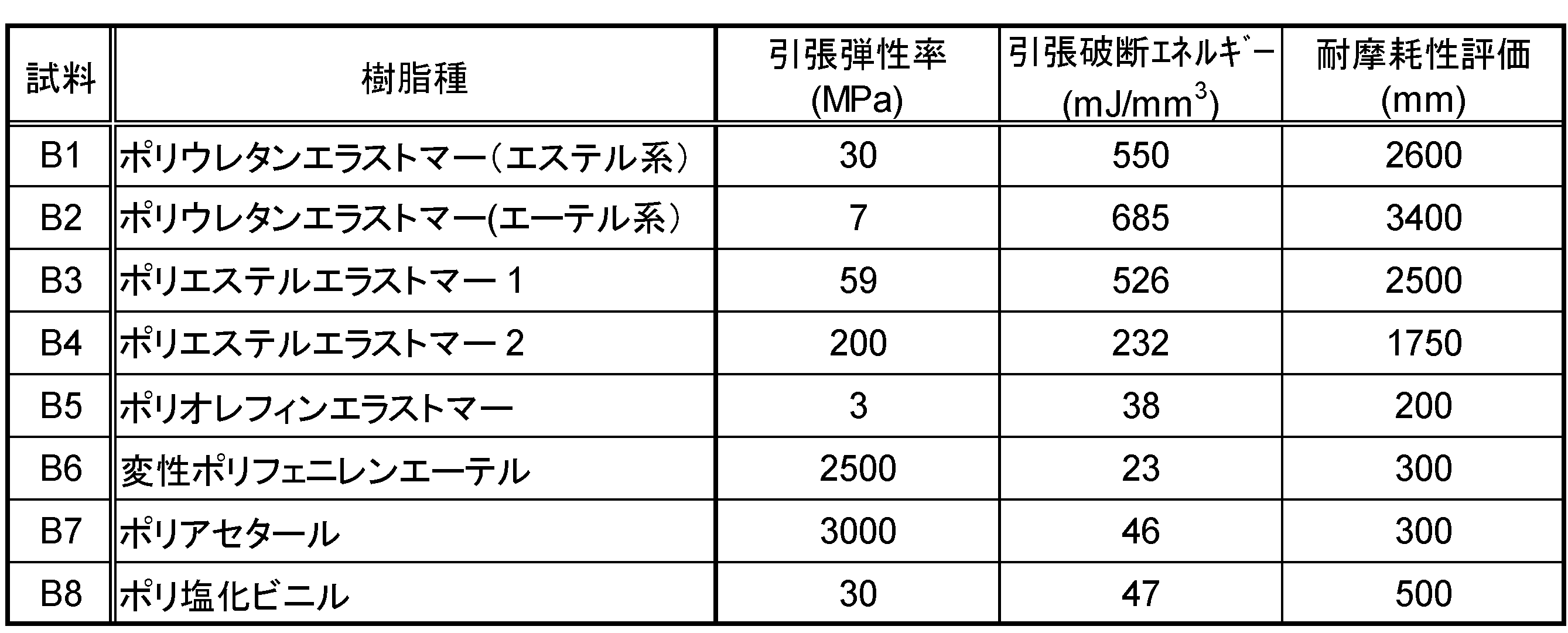
表3および図3によると、引張破断エネルギーと耐摩耗性の評価結果の間には、引張破断エネルギーが大きくなるほど耐摩耗性が高くなるという傾向が見られている。図3中に点線で示すように、両者の関係は、概ね直線に近似することができる。各試料を構成する樹脂種は多様であり、そのような相関性が樹脂種を超えて成立していると言える。この結果は、樹脂材料の引張破断エネルギーが、耐摩耗性の指標として優れていることを示している。
特に、熱可塑性エラストマーを絶縁被覆に用いた試料B1~B4においては、引張破断エネルギーが200mJ/mm3以上の大きな値を示している。そして、それに対応して、耐摩耗性の評価結果が、1500mmを超える大きな値となっている。
表3には、各樹脂種の引張弾性率も併せて示している。引張破断エネルギーとは異なり、引張弾性率は、耐摩耗性との間に明確な相関性を有していないことが明らかである。
以上、本発明の実施の形態について詳細に説明したが、本発明は上記実施の形態に何ら限定されるものではなく、本発明の要旨を逸脱しない範囲で種々の改変が可能である。
10 絶縁電線
12 電線導体
12a 素線
14 絶縁被覆
12 電線導体
12a 素線
14 絶縁被覆
Claims (7)
- 電線導体と、前記電線導体の外周を被覆する絶縁被覆と、を有し、
前記絶縁被覆は、熱可塑性ポリウレタンエラストマーを主成分とする樹脂組成物よりなることを特徴とする絶縁電線。 - 前記絶縁被覆の厚さは、0.7mm未満であることを特徴とする請求項1に記載の絶縁電線。
- 前記樹脂組成物の引張破断エネルギーは、200mJ/mm3以上であることを特徴とする請求項1または2に記載の絶縁電線。
- 前記熱可塑性ポリウレタンエラストマーの硬度は、JIS A硬度で、85以上であることを特徴とする請求項1から3のいずれか1項に記載の絶縁電線。
- 前記熱可塑性ポリウレタンエラストマーは、エーテル系熱可塑性ポリウレタンエラストマーであることを特徴とする請求項1から4のいずれか1項に記載の絶縁電線。
- 前記電線導体の導体断面積は、3mm2以上、20mm2以下であることを特徴とする請求項1から5のいずれか1項に記載の絶縁電線。
- 請求項1から6のいずれか1項に記載の絶縁電線を含むことを特徴とするワイヤーハーネス。
Priority Applications (4)
| Application Number | Priority Date | Filing Date | Title |
|---|---|---|---|
| JP2019525101A JPWO2018235368A1 (ja) | 2017-06-19 | 2018-03-23 | 絶縁電線およびワイヤーハーネス |
| DE112018003122.5T DE112018003122T5 (de) | 2017-06-19 | 2018-03-23 | Isolierter elektrischer Draht und Kabelbaum |
| US16/623,460 US20200118704A1 (en) | 2017-06-19 | 2018-03-23 | Insulated electric wire and wire harness |
| CN201880039333.1A CN110770856A (zh) | 2017-06-19 | 2018-03-23 | 绝缘电线和线束 |
Applications Claiming Priority (2)
| Application Number | Priority Date | Filing Date | Title |
|---|---|---|---|
| JP2017119851 | 2017-06-19 | ||
| JP2017-119851 | 2017-06-19 |
Publications (1)
| Publication Number | Publication Date |
|---|---|
| WO2018235368A1 true WO2018235368A1 (ja) | 2018-12-27 |
Family
ID=64735630
Family Applications (1)
| Application Number | Title | Priority Date | Filing Date |
|---|---|---|---|
| PCT/JP2018/011646 Ceased WO2018235368A1 (ja) | 2017-06-19 | 2018-03-23 | 絶縁電線およびワイヤーハーネス |
Country Status (5)
| Country | Link |
|---|---|
| US (1) | US20200118704A1 (ja) |
| JP (1) | JPWO2018235368A1 (ja) |
| CN (1) | CN110770856A (ja) |
| DE (1) | DE112018003122T5 (ja) |
| WO (1) | WO2018235368A1 (ja) |
Cited By (2)
| Publication number | Priority date | Publication date | Assignee | Title |
|---|---|---|---|---|
| US20220084721A1 (en) * | 2019-01-16 | 2022-03-17 | Autonetworks Technologies, Ltd. | Insulated wire with bonding layer |
| JP7608232B2 (ja) | 2021-03-25 | 2025-01-06 | 古河電気工業株式会社 | 被覆導線、端子付き電線およびワイヤハーネス |
Families Citing this family (1)
| Publication number | Priority date | Publication date | Assignee | Title |
|---|---|---|---|---|
| JP7147839B2 (ja) * | 2018-03-28 | 2022-10-05 | 株式会社オートネットワーク技術研究所 | ワイヤーハーネスおよびワイヤーハーネスの製造方法 |
Citations (2)
| Publication number | Priority date | Publication date | Assignee | Title |
|---|---|---|---|---|
| US4734545A (en) * | 1986-11-26 | 1988-03-29 | The Furukawa Electric Co., Ltd. | Insulated conductor for a wire harness |
| JP2012518693A (ja) * | 2009-02-20 | 2012-08-16 | ディーエスエム アイピー アセッツ ビー.ブイ. | 非ブルーム性難燃熱可塑性組成物 |
Family Cites Families (9)
| Publication number | Priority date | Publication date | Assignee | Title |
|---|---|---|---|---|
| JP2628640B2 (ja) * | 1986-12-02 | 1997-07-09 | 古河電気工業株式会社 | 難燃性熱可塑性ポリウレタン樹脂組成物 |
| JP3846757B2 (ja) * | 1997-08-06 | 2006-11-15 | 古河電気工業株式会社 | ケーブル |
| US20040035854A1 (en) * | 2002-08-22 | 2004-02-26 | Chung-Chi Cheng | Electric heating wire and applications thereof |
| JP2008123755A (ja) * | 2006-11-09 | 2008-05-29 | Auto Network Gijutsu Kenkyusho:Kk | フラットケーブル |
| EP2584567B1 (de) * | 2011-10-20 | 2016-02-10 | Nexans | Leicht abzumantelndes elektrisches kabel |
| CN103050186B (zh) * | 2012-08-31 | 2015-11-11 | 上海福尔欣线缆有限公司 | 一种防抱死刹车系统汽车电缆及其制造方法 |
| CN204087874U (zh) * | 2014-07-18 | 2015-01-07 | 焦作市森格高新材料有限责任公司 | 一种超柔耐磨防水极低噪音单晶铜多信道音频电缆 |
| JP2016201220A (ja) * | 2015-04-08 | 2016-12-01 | 住友電気工業株式会社 | 電線及びその製造方法、並びに多芯ケーブル及びその製造方法 |
| CN204516448U (zh) * | 2015-04-14 | 2015-07-29 | 江苏天力电缆有限公司 | 新型铝合金电缆 |
-
2018
- 2018-03-23 DE DE112018003122.5T patent/DE112018003122T5/de active Pending
- 2018-03-23 US US16/623,460 patent/US20200118704A1/en not_active Abandoned
- 2018-03-23 WO PCT/JP2018/011646 patent/WO2018235368A1/ja not_active Ceased
- 2018-03-23 JP JP2019525101A patent/JPWO2018235368A1/ja active Pending
- 2018-03-23 CN CN201880039333.1A patent/CN110770856A/zh active Pending
Patent Citations (2)
| Publication number | Priority date | Publication date | Assignee | Title |
|---|---|---|---|---|
| US4734545A (en) * | 1986-11-26 | 1988-03-29 | The Furukawa Electric Co., Ltd. | Insulated conductor for a wire harness |
| JP2012518693A (ja) * | 2009-02-20 | 2012-08-16 | ディーエスエム アイピー アセッツ ビー.ブイ. | 非ブルーム性難燃熱可塑性組成物 |
Cited By (3)
| Publication number | Priority date | Publication date | Assignee | Title |
|---|---|---|---|---|
| US20220084721A1 (en) * | 2019-01-16 | 2022-03-17 | Autonetworks Technologies, Ltd. | Insulated wire with bonding layer |
| US12014849B2 (en) * | 2019-01-16 | 2024-06-18 | Autonetworks Technologies, Ltd. | Insulated wire with bonding layer of polyolefin and polyamide |
| JP7608232B2 (ja) | 2021-03-25 | 2025-01-06 | 古河電気工業株式会社 | 被覆導線、端子付き電線およびワイヤハーネス |
Also Published As
| Publication number | Publication date |
|---|---|
| US20200118704A1 (en) | 2020-04-16 |
| CN110770856A (zh) | 2020-02-07 |
| JPWO2018235368A1 (ja) | 2020-01-09 |
| DE112018003122T5 (de) | 2020-03-05 |
Similar Documents
| Publication | Publication Date | Title |
|---|---|---|
| CN103597549B (zh) | 电线被覆材料、绝缘电线以及线束 | |
| WO2018235368A1 (ja) | 絶縁電線およびワイヤーハーネス | |
| CN102459669A (zh) | 电线导体和汽车用电线 | |
| US11996217B2 (en) | Shielded cable | |
| JP2014229501A (ja) | 電線被覆材料及び被覆電線 | |
| JP2008159403A (ja) | 電線導体および絶縁電線 | |
| WO2006008981A1 (ja) | 自動車用電線 | |
| JP6860071B2 (ja) | 絶縁電線およびワイヤーハーネス | |
| EP3113190A1 (en) | Stranded conductor and insulated wire | |
| WO2016076085A1 (ja) | 電線被覆材用組成物および絶縁電線 | |
| JP6406098B2 (ja) | 絶縁電線 | |
| JP2014177510A (ja) | 絶縁体組成物及びこれを用いた被覆電線 | |
| JP6854203B2 (ja) | 高柔軟電線及びインホイールモーター用ケーブル | |
| JP2011252185A (ja) | Al合金導電線 | |
| JP5608993B2 (ja) | 自動車用電線導体および自動車用電線 | |
| JP7166970B2 (ja) | ワイヤーハーネス用撚り線 | |
| JP2005197135A (ja) | 自動車用電源線 | |
| JP7793978B2 (ja) | シールドケーブル | |
| JP7108513B2 (ja) | キャブタイヤケーブルおよびキャブタイヤケーブルの製造方法 | |
| JP2012186126A (ja) | 細径ツイストペアケーブル | |
| JP2006032076A (ja) | 自動車用電線 | |
| CN106205810A (zh) | 一种具有共混弹性体绝缘及耐拖拽磨损的软电缆 | |
| JP2015191773A (ja) | 絶縁電線およびワイヤーハーネス | |
| CN120048578A (zh) | 可在低温环境中使用的电线 | |
| JP2023069558A (ja) | 太物電線 |
Legal Events
| Date | Code | Title | Description |
|---|---|---|---|
| 121 | Ep: the epo has been informed by wipo that ep was designated in this application |
Ref document number: 18821339 Country of ref document: EP Kind code of ref document: A1 |
|
| ENP | Entry into the national phase |
Ref document number: 2019525101 Country of ref document: JP Kind code of ref document: A |
|
| 122 | Ep: pct application non-entry in european phase |
Ref document number: 18821339 Country of ref document: EP Kind code of ref document: A1 |