WO2018235275A1 - Onboard device for closing/opening vehicle door locks, vehicle provided with onboard device, and vehicle door lock closing/opening system provided with onboard device - Google Patents
Onboard device for closing/opening vehicle door locks, vehicle provided with onboard device, and vehicle door lock closing/opening system provided with onboard device Download PDFInfo
- Publication number
- WO2018235275A1 WO2018235275A1 PCT/JP2017/023245 JP2017023245W WO2018235275A1 WO 2018235275 A1 WO2018235275 A1 WO 2018235275A1 JP 2017023245 W JP2017023245 W JP 2017023245W WO 2018235275 A1 WO2018235275 A1 WO 2018235275A1
- Authority
- WO
- WIPO (PCT)
- Prior art keywords
- vehicle
- door lock
- relay
- unlocking
- locking
- Prior art date
Links
Images


Classifications
-
- G—PHYSICS
- G07—CHECKING-DEVICES
- G07C—TIME OR ATTENDANCE REGISTERS; REGISTERING OR INDICATING THE WORKING OF MACHINES; GENERATING RANDOM NUMBERS; VOTING OR LOTTERY APPARATUS; ARRANGEMENTS, SYSTEMS OR APPARATUS FOR CHECKING NOT PROVIDED FOR ELSEWHERE
- G07C9/00—Individual registration on entry or exit
- G07C9/00174—Electronically operated locks; Circuits therefor; Nonmechanical keys therefor, e.g. passive or active electrical keys or other data carriers without mechanical keys
- G07C9/00571—Electronically operated locks; Circuits therefor; Nonmechanical keys therefor, e.g. passive or active electrical keys or other data carriers without mechanical keys operated by interacting with a central unit
-
- B—PERFORMING OPERATIONS; TRANSPORTING
- B60—VEHICLES IN GENERAL
- B60R—VEHICLES, VEHICLE FITTINGS, OR VEHICLE PARTS, NOT OTHERWISE PROVIDED FOR
- B60R25/00—Fittings or systems for preventing or indicating unauthorised use or theft of vehicles
- B60R25/01—Fittings or systems for preventing or indicating unauthorised use or theft of vehicles operating on vehicle systems or fittings, e.g. on doors, seats or windscreens
-
- B—PERFORMING OPERATIONS; TRANSPORTING
- B60—VEHICLES IN GENERAL
- B60R—VEHICLES, VEHICLE FITTINGS, OR VEHICLE PARTS, NOT OTHERWISE PROVIDED FOR
- B60R25/00—Fittings or systems for preventing or indicating unauthorised use or theft of vehicles
- B60R25/20—Means to switch the anti-theft system on or off
- B60R25/24—Means to switch the anti-theft system on or off using electronic identifiers containing a code not memorised by the user
-
- E—FIXED CONSTRUCTIONS
- E05—LOCKS; KEYS; WINDOW OR DOOR FITTINGS; SAFES
- E05B—LOCKS; ACCESSORIES THEREFOR; HANDCUFFS
- E05B49/00—Electric permutation locks; Circuits therefor ; Mechanical aspects of electronic locks; Mechanical keys therefor
-
- E—FIXED CONSTRUCTIONS
- E05—LOCKS; KEYS; WINDOW OR DOOR FITTINGS; SAFES
- E05B—LOCKS; ACCESSORIES THEREFOR; HANDCUFFS
- E05B81/00—Power-actuated vehicle locks
- E05B81/54—Electrical circuits
-
- E—FIXED CONSTRUCTIONS
- E05—LOCKS; KEYS; WINDOW OR DOOR FITTINGS; SAFES
- E05B—LOCKS; ACCESSORIES THEREFOR; HANDCUFFS
- E05B81/00—Power-actuated vehicle locks
- E05B81/54—Electrical circuits
- E05B81/64—Monitoring or sensing, e.g. by using switches or sensors
-
- G—PHYSICS
- G07—CHECKING-DEVICES
- G07C—TIME OR ATTENDANCE REGISTERS; REGISTERING OR INDICATING THE WORKING OF MACHINES; GENERATING RANDOM NUMBERS; VOTING OR LOTTERY APPARATUS; ARRANGEMENTS, SYSTEMS OR APPARATUS FOR CHECKING NOT PROVIDED FOR ELSEWHERE
- G07C9/00—Individual registration on entry or exit
- G07C9/00174—Electronically operated locks; Circuits therefor; Nonmechanical keys therefor, e.g. passive or active electrical keys or other data carriers without mechanical keys
-
- H—ELECTRICITY
- H04—ELECTRIC COMMUNICATION TECHNIQUE
- H04M—TELEPHONIC COMMUNICATION
- H04M11/00—Telephonic communication systems specially adapted for combination with other electrical systems
-
- H—ELECTRICITY
- H04—ELECTRIC COMMUNICATION TECHNIQUE
- H04Q—SELECTING
- H04Q9/00—Arrangements in telecontrol or telemetry systems for selectively calling a substation from a main station, in which substation desired apparatus is selected for applying a control signal thereto or for obtaining measured values therefrom
-
- G—PHYSICS
- G07—CHECKING-DEVICES
- G07C—TIME OR ATTENDANCE REGISTERS; REGISTERING OR INDICATING THE WORKING OF MACHINES; GENERATING RANDOM NUMBERS; VOTING OR LOTTERY APPARATUS; ARRANGEMENTS, SYSTEMS OR APPARATUS FOR CHECKING NOT PROVIDED FOR ELSEWHERE
- G07C9/00—Individual registration on entry or exit
- G07C9/00174—Electronically operated locks; Circuits therefor; Nonmechanical keys therefor, e.g. passive or active electrical keys or other data carriers without mechanical keys
- G07C9/00182—Electronically operated locks; Circuits therefor; Nonmechanical keys therefor, e.g. passive or active electrical keys or other data carriers without mechanical keys operated with unidirectional data transmission between data carrier and locks
- G07C2009/00261—Electronically operated locks; Circuits therefor; Nonmechanical keys therefor, e.g. passive or active electrical keys or other data carriers without mechanical keys operated with unidirectional data transmission between data carrier and locks the keyless data carrier having more than one function
- G07C2009/00293—Electronically operated locks; Circuits therefor; Nonmechanical keys therefor, e.g. passive or active electrical keys or other data carriers without mechanical keys operated with unidirectional data transmission between data carrier and locks the keyless data carrier having more than one function anti-theft
Definitions
- the present invention relates to a vehicle door lock locking and unlocking on-vehicle unit that can be used for car rental and car sharing, a vehicle equipped with this on-vehicle unit, and a vehicle door lock locking and unlocking system equipped with this on-vehicle unit
- the present invention relates to a vehicle door lock locking and unlocking system for locking and unlocking a vehicle door lock using an on-board unit provided with communication means for receiving a locking instruction or an unlocking instruction directly from a user terminal or via a server. It is a thing.
- car sharing there are car rental and car sharing as well as owning and car leasing as modes of use of the vehicle, but in recent years, car sharing in which a plurality of users share the vehicle has become widespread.
- car sharing is convenient for users who want to use a vehicle only for a short time, users who want to use a vehicle only at a specific date and time, etc., and the vehicle is shared by multiple users. Because it can be used, utilization efficiency is increased, and there are merits in cost.
- Patent Document 1 when a user uses a vehicle, when a user request such as a mobile phone transmits a user request to a remote user server, the remote user server authenticates the user and solves the remote vehicle server. Send a lock request.
- the remote vehicle server having received the unlock request transmits a request for unlocking the door to the communication device of the vehicle, and then the request for unlocking the door lock from the communication device of the vehicle is the vehicle's request. Transmitted to the control system, the control system of the vehicle unlocks the door lock of the vehicle.
- Patent Document 1 when the communication device of the vehicle receives a request for locking or unlocking the door lock from the remote vehicle server, the request for locking or unlocking the door lock is transmitted from the communication device of the vehicle to the ECU, etc.
- the door lock is locked or unlocked by being transmitted to the control system of the vehicle.
- a request for locking or unlocking is processed by a control system of a vehicle such as an ECU.
- a communication method between an ECU and a communication device or a door lock system in a vehicle a communication method such as CAN is generally used.
- CAN Controller Area Network
- LIN Local Interconnect Network
- FlexRay etc.
- CAN is the most widely used protocol among in-vehicle control networks, and is installed in many vehicles currently sold.
- CAN is vulnerable to security.
- spoofing messages can be injected to enable unauthorized control such as tampering with the display of the meter or disabling the brake.
- the vehicle is provided with a self-diagnosis function of the vehicle called OBD (On-Board Diagnostics second generation).
- OBD On-Board Diagnostics second generation
- OBD 2 On-Board Diagnostics second generation
- CAN information for example, fuel consumption information, speed information, and the like
- the subject of the present application is a vehicle door lock for locking and unlocking a vehicle door lock for car rental and car sharing, and an in-vehicle device for locking and unlocking the vehicle door lock.
- An object of the present invention is to provide a vehicle door lock locking and unlocking in-vehicle device capable of locking and unlocking the door lock of the vehicle without the vehicle-mounted device via the ECU or CAN of the vehicle.
- the vehicle-mounted device is via the ECU or CAN of the vehicle. It is an object of the present invention to provide a vehicle door lock locking and unlocking on-vehicle unit according to the wiring of a door lock actuator control circuit while being able to lock and unlock the door lock of the vehicle.
- Another subject of the present application is a vehicle door lock for locking and unlocking a vehicle door lock for car rental and car sharing, and a vehicle door lock via a server from a user terminal in a vehicle door lock locking and unlocking device. It is an object of the present invention to provide a vehicle door lock locking and unlocking in-vehicle device which can lock and unlock the vehicle and can lock and unlock the door lock of the vehicle without the vehicle-mounted device via the ECU or CAN of the vehicle.
- another subject of the present application is a vehicle door lock for locking and unlocking a vehicle door lock for car rental and car sharing, and a door lock for the vehicle lock directly from the user terminal in the vehicle door lock for locking and unlocking. It is an object of the present invention to provide a vehicle door lock locking and unlocking vehicle-mounted device capable of transmitting a locking and unlocking command of the vehicle and capable of locking and unlocking the door lock of the vehicle without the vehicle-mounted device via the ECU or CAN of the vehicle.
- An object of the present invention is to provide a system for locking and unlocking a vehicle door lock that can switch a vehicle from a bootable state to a non-bootable state according to a control command.
- Another problem of the present application is that, when the vehicle is switched from the bootable state to the non-bootable state, in consideration of the safety of the vehicle, the vehicle is placed in a dangerous place or a place where other people are annoyed. It is an object of the present invention to provide a vehicle door lock locking and unlocking system capable of preventing a non-startable state.
- Another object of the present invention is to provide a vehicle provided with the vehicle door lock locking and unlocking on-vehicle device.
- Another object of the present invention is to provide a vehicle door lock locking and unlocking system including the vehicle door lock locking and unlocking on-vehicle unit.
- Another object of the present invention is to provide a vehicle door lock locking and unlocking system capable of making reservation of a vehicle and managing door lock key information.
- Another object of the present invention is to provide a vehicle door lock locking and unlocking system capable of transmitting a locking instruction or unlocking instruction from a server to an on-vehicle device of a vehicle even in the absence of a user terminal. is there.
- the above object of the present invention can be achieved by the following constitution. That is, in the vehicle-mounted device according to the first aspect of the present invention, communication means for receiving a locking command or an unlocking command directly from a user terminal or via a server, and wiring between a door key switch of a vehicle and a door lock actuator. And at least one internal relay connected, wherein the internal relay controls the at least one external relay to lock or lock the door lock of the vehicle.
- the door lock actuator is driven in the first direction to lock the door lock by changing the state of the internal relay for a certain period of time.
- the unlocking command is received, the state of the internal relay changes for a certain period of time, whereby the door lock actuator operates in the second state. It is characterized in that it is driven in a direction to unlock the door lock.
- the vehicle-mounted device is the vehicle-mounted device according to the first aspect, wherein the door lock actuator is any one of a door lock motor unit, a vacuum pump unit, or a centralized door lock module. It is characterized by
- a vehicle-mounted device is the vehicle-mounted device according to the first or second aspect, wherein the internal relay includes a first internal relay and a second internal relay, and the first internal relay and / or the first internal relay 2)
- the internal relay controls the locking or unlocking of the door lock of the vehicle by controlling at least one external relay, and when the locking command is received, the state of the first internal relay is fixed for a certain period of time Due to the change, when the door lock actuator is driven in the first direction to lock the door lock and the unlock command is received, the state of the second internal relay changes for a certain period of time. Thus, the door lock actuator is driven in the second direction to unlock the door lock.
- a vehicle-mounted device is characterized in that, in the vehicle-mounted device according to any one of the first to third aspects, the external relay includes a first external relay and a second external relay.
- the vehicle-mounted device is the vehicle-mounted device according to the fourth aspect, wherein the door lock actuator is supplied with power by two feeders, and when the locking command is received When the state of the first internal relay changes, one of the feeders is grounded by the first external relay, whereby the door lock actuator is driven in the first direction to lock the door lock. When the unlocking command is received, the state of the second internal relay changes for a certain period of time, whereby the other of the feeders is grounded by the second external relay, whereby the door lock is achieved.
- the actuator may be driven in a second direction to unlock the door lock.
- the vehicle-mounted device is the vehicle-mounted device according to the fourth aspect, wherein the door lock actuator is supplied with power by two feeders, and when the locking command is received When the state of the first internal relay changes, a power supply voltage is applied to the one of the feeders from the first external relay, whereby the door lock actuator is driven in a first direction, and the door lock is performed. Is locked and when the unlock command is received, the power supply voltage is applied from the second external relay to the other of the feeder lines by changing the state of the second internal relay for a certain period of time. Thus, the door lock actuator is driven in the second direction to unlock the door lock.
- the vehicle-mounted device is the vehicle-mounted device according to the fourth aspect, wherein the door lock actuator is supplied with power by two feeders, and the first feeder is connected to the two feeders. And the second external relay is connected, and is connected to the door lock relay unit, and when the locking command is received, the state of the first internal relay changes for a certain period of time.
- the door lock actuator is supplied with power by two feeders, and the first feeder is connected to the two feeders.
- the second external relay is connected, and is connected to the door lock relay unit, and when the locking command is received, the state of the first internal relay changes for a certain period of time.
- the power supply voltage is applied to one of the feeders from the first external relay, the door lock actuator is driven in the first direction, the door lock is locked, and the unlock command is received.
- the state of the second internal relay changes for a certain period of time
- the power supply voltage is applied from the second external relay to the other of the power supply lines, whereby the door lock is activated. Yueta said door
- the vehicle-mounted device is the vehicle-mounted device according to the fourth aspect, wherein the door lock actuator is fed by two feed lines, and the first feed relay is connected to the two feed lines. And the door lock relay unit is connected via the second external relay, and at least a part of the wiring of the portion bypassed by the first external relay and the second external relay is disconnected,
- the power supply voltage is applied to the one of the feeders from the first external relay, whereby the door lock actuator is driven by the first
- the state of the second internal relay changes for a certain period of time
- serial other to the power supply voltage from the second external device of the power supply line is applied, the door lock the door lock actuator is driven in the second direction, characterized in that it is unlocked.
- the vehicle-mounted device is the vehicle-mounted device according to the fourth aspect, wherein the door lock actuator is supplied with power by a single feeder line, and the first external relay and the second The wiring of at least a part of the part connected via the external relay and bypassed by the first external relay and the second external relay is disconnected, and when the locking command is received, the fixed time is set.
- the state of the first internal relay changes, the one feed line is grounded, whereby the door lock actuator is driven in a first direction to lock the door lock, and the unlocking is performed.
- the state of the second internal relay changes for a certain period of time, whereby a power supply voltage is applied to the one feed line, thereby causing the door lock actu
- the door lock over data is driven to the second direction, characterized in that it is unlocked.
- the vehicle-mounted device is the vehicle-mounted device according to the third aspect, wherein the door lock actuator is supplied with power by a single feeder line, and the single feeder line is connected via a first external relay. At least a part of the wiring of the part connected and bypassed by the first external relay is disconnected, and when the locking command is received, the state of the first internal relay changes for a certain period of time.
- the door lock actuator is driven in the second direction by the one feed line being grounded by changing the state of the second internal relay for a certain period of time. Characterized in that the door lock is unlocked.
- the vehicle-mounted device is the vehicle-mounted device according to any of the first to tenth aspects, wherein the communication unit receives an unlocking command or a locking command from a user terminal via a server. It is characterized by
- the vehicle-mounted device is characterized in that, in the vehicle-mounted device according to any of the first to tenth aspects, the communication means directly receives an unlocking command or a locking command from a user terminal.
- the vehicle-mounted device is the vehicle-mounted device according to any of the first to twelfth aspects, wherein the communication means switches an engine start relaying state between the server and the vehicle start impossible state.
- the vehicle-mounted device is the vehicle-mounted device according to the thirteenth aspect, wherein the vehicle-mounted device further comprises vehicle information detection means for detecting at least an on / off state of vehicle power; The external relay is controlled based on the elapsed time after the on / off state of the vehicle power detected by the vehicle information detection means is changed.
- a vehicle according to a fifteenth aspect of the present invention includes the vehicle-mounted device according to any one of the first to fourteenth aspects.
- a system according to a sixteenth aspect of the present invention includes the vehicle-mounted device according to any one of the first to fourteenth aspects.
- the system according to a seventeenth aspect of the present invention is characterized in that, in the system according to the sixteenth aspect, the server reserves a specific vehicle based on an operation from a user terminal.
- the system according to an eighteenth aspect of the present invention is the system according to the seventeenth aspect, wherein the server is configured to, in advance, provide the door lock key information corresponding to the on-vehicle device of the specific vehicle based on the reservation information to the user terminal.
- the transmission is characterized in that the user terminal transmits a locking instruction or an unlocking instruction to the in-vehicle device directly or via the server to the in-vehicle device based on the door lock key information.
- the system according to a nineteenth aspect of the present invention is the system according to any one of the sixteenth to eighteenth aspects, wherein there is a problem with payment for the reservation if the particular vehicle is used without prior reservation.
- the specific vehicle is used for a predetermined period or more beyond the period of the reservation without prior extension procedure, the geographical range using the specific vehicle exceeds the range set at the time of reservation or, if the mode of use of the specific vehicle violates the condition set at the time of reservation, the server sends an engine start relay control command for switching the vehicle to the start impossible state to the on-vehicle device of the specific vehicle. It is characterized by transmitting.
- the system according to a twentieth aspect of the present invention is the system according to any one of the seventeenth to nineteenth aspects, wherein the server confirms and confirms the reservation even when the door lock key information is not sent from the user terminal.
- the server transmits a locking instruction or an unlocking instruction to the on-vehicle device of the specific vehicle.
- the vehicle-mounted device in the vehicle-door lock for locking and unlocking the vehicle door lock for car rental and car sharing, the vehicle-mounted device is via the ECU of the vehicle Can lock and unlock the vehicle door lock.
- the vehicle-mounted device of the second aspect it is possible to correspond to various door lock actuators.
- the vehicle-mounted device of the third aspect by providing two internal relays, it is possible to provide a vehicle door lock locking and unlocking vehicle-mounted device capable of driving the door lock actuator in the locking direction or the unlocking direction. Can.
- the two external relays can be appropriately controlled.
- the vehicle-mounted device of the fifth to tenth aspects it is possible to provide a vehicle door lock locking and unlocking vehicle-mounted device according to the wiring of the door lock actuator control circuit.
- the vehicle-door lock for locking and unlocking the vehicle door lock for car rental and car sharing is an on-vehicle device for locking and unlocking the vehicle through the server from the user terminal.
- a door lock can be locked and unlocked, and a vehicle door lock locking and unlocking vehicle can be provided that can lock and unlock the door lock of the vehicle without the vehicle-mounted device via the ECU of the vehicle.
- the vehicle-door lock for locking and unlocking the vehicle door lock for car rental and car sharing, directly on the vehicle-mounted device from the user terminal, in the vehicle door lock.
- a vehicle door lock locking and unlocking on-vehicle unit capable of transmitting a locking and unlocking command of the door lock and also capable of locking and unlocking the door lock of the vehicle without the vehicle-mounted device via the ECU of the vehicle.
- the engine from the server is used when the vehicle is used without prior reservation, or when the mode of use of a specific vehicle violates the conditions set at the time of reservation.
- the start relay control command it is possible to provide a vehicle door lock locking and unlocking system capable of switching the vehicle from the startable state to the start impossible state.
- another problem of the present application is that when the vehicle is switched from the bootable state to the non-bootable state, considering the safety of the vehicle, the vehicle may be dangerous or a nuisance to others Can be prevented from becoming unbootable when placed in a place where
- the vehicle of the fifteenth aspect it is possible to provide a vehicle having the effects of the vehicle door lock and lock on-vehicle lock.
- the vehicle can be switched to the non-startable state when necessary.
- locking and unlocking of the door lock of the vehicle can be controlled by transmitting the locking instruction or the unlocking instruction from the server to the on-vehicle device of the vehicle even when there is no user terminal.
- FIG. 1 is a block diagram of a vehicle-mounted device according to a first embodiment.
- FIG. 1 is a conceptual view of a car sharing system according to a first embodiment.
- FIG. 2 is a wiring diagram of a door lock actuator control circuit according to a first embodiment.
- FIG. 5 is an explanatory diagram of a relay value
- FIG. 5A is an explanatory diagram of a case where a start control line is a single vehicle type
- FIG. 5B is an explanatory diagram of a case where a start control line is a two vehicle type. It is explanatory drawing of wiring of a relay.
- FIG. 10 is an overall view of a vehicle door lock locking and unlocking system according to a second embodiment. It is. FIG. 10 is a wiring diagram of a door lock actuator control circuit according to a third embodiment. FIG. 10 is a wiring diagram of a door lock actuator control circuit according to a fourth embodiment. FIG. 16 is a wiring diagram of a door lock actuator control circuit according to a fifth embodiment. FIG. 16 is a wiring diagram of a door lock actuator control circuit according to a sixth embodiment. FIG. 18 is a wiring diagram of a door lock actuator control circuit according to a seventh embodiment. It is explanatory drawing of the start impossible state for every vehicle type.
- Embodiment 1 A vehicle door lock locking and unlocking system according to a first embodiment of the present invention will be described with reference to FIGS. 1 to 10.
- a system is described in which a locking command or unlocking command can be transmitted from the user terminal 37 to the on-board unit 1 of the vehicle 2 via the server 3 to lock or unlock the door lock of the vehicle by the on-board unit 1 .
- the terms inner relay and outer relay are used in connection with the locking and unlocking of the door lock.
- an internal combustion engine vehicle traveling using an internal combustion engine such as a gasoline engine is exemplified for the operation of switching the vehicle to the start impossible state, and an engine start control line of the internal combustion engine
- wire 23 is demonstrated.
- the terms such as the engine start relay input / output 18 and the engine start external relay 20 are used to distinguish from the above terms internal relay and external relay.
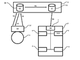
- FIG. 1 is an overall view of a vehicle door lock locking and unlocking system used for car rental or car sharing.
- a specific vehicle is used without prior reservation in car rental or car sharing, if there is a problem with payment for the reservation, the specific vehicle for a predetermined period of time beyond the period of the reservation without prior extension procedure If the geographical range in which the specific vehicle is used exceeds the range set at the time of booking, or if the mode of use of the particular vehicle is contrary to the conditions set at the time of booking. In such a case, a service for remotely stopping (starting impossible) the vehicle and specifying the position of the vehicle for recovery is realized.
- car rental or car sharing will be described, but the present invention is not limited to this, and is applicable to those where it is necessary to remotely stop the vehicle (non-startable state), For example, it is applicable to a car lease.
- this system is applied to a car lease, the vehicle is provided to the user, and if the user does not pay the usage charge (for example, a monthly charge) within a predetermined period, the vehicle is remotely stopped (start impossible state) In addition to this, it is possible to realize a service for specifying and recovering the position of the vehicle.
- the usage charge for example, a monthly charge
- 2 is a vehicle provided to the user
- 1 is an in-vehicle device installed in the vehicle 2
- 3 is in communication with the in-vehicle device 1 to manage locking and unlocking of each vehicle, and is communicated with a user terminal 37 to reserve a vehicle Is a server that manages
- One vehicle-mounted device 1 is installed in one vehicle.
- the installation location of the vehicle-mounted device 1 in the vehicle 2 may be any location of the vehicle 2 as long as the vehicle-mounted device 1 can control the vehicle 2 as described later.
- the vehicle-mounted device 1 can be disposed at a place where the installation work is easy, such as under the seat of the passenger seat. Further, from the viewpoint of theft prevention, the vehicle-mounted device 1 can be disposed in a place where removal is difficult, for example, in the lower part of the engine room or inside the instrument panel. Furthermore, the vehicle-mounted device 1 can be incorporated in advance at the time of manufacture of the vehicle 2.
- the in-vehicle device 1 transmits the vehicle information of the vehicle 2 collected by the vehicle information detection means to the server via the wireless communication network 34, and also the locking instruction, unlocking instruction, engine from the server 3 via the wireless communication network 34.
- the activation relay control signal is received to control a door lock actuator 29 of the vehicle 2 and an engine activation external relay 20 (see FIG. 2) which will be described later.
- By controlling the door lock actuator 29, locking and unlocking of the door lock of the vehicle can be remotely controlled through the server 3 based on the locking command and the unlocking command from the user terminal.
- the engine start external relay 20 by controlling the engine start external relay 20, it is possible to switch between the start impossible state and the start possible state of the vehicle.
- the engine can not be started in the non-startable state (not for turning off the engine during start-up, but it is prohibited to restart the engine), and start the engine in the startable state.
- the wireless communication network 34 may be any one as long as communication between the onboard unit 1 and the server 3 is possible, for example, 2G, 3G, 4G, 5G, Wi-Fi (registered trademark), WiMAX (Registered trademark), wireless LAN, beacon, Bluetooth (registered trademark), ZigBee (registered trademark), and the like.
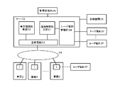
- the server 3 includes a user information management unit 38, a remote control instruction unit 31, a vehicle information collection unit 32, and a transmission / reception unit 33.
- the user information management unit 38 manages reservation of the vehicle by communication with the user terminal 37, transmits door lock key information to the user terminal 37 according to the reservation situation, and gives a locking instruction and unlocking instruction from the user terminal 37.
- Accept The remote control instructing unit 31 generates a lock command, an unlock command, and an engine start relay control command for the vehicle-mounted device 1.
- the vehicle information collection unit 32 collects vehicle information from the on-board unit 1.
- the transmitting and receiving unit 33 transmits and receives data to and from the on-vehicle device.
- the server 3 is connected to the manager terminal 35 and the financial institution 36.
- the user terminal 37 is preferably a portable terminal such as a smart phone, a mobile phone or a tablet terminal, and needs to be at least portable in order to be used as a door lock key of the vehicle. Furthermore, the vehicle 2 and the user terminal 37 have a GPS function. It is desirable to have. Since the vehicle 2 and the user terminal 37 have the GPS function, the server 3 can grasp the position of the vehicle by the GPS mounted on the vehicle 2 and can grasp the position of the user by the GPS of the user terminal 37. It can be determined whether the locking command and the unlocking command transmitted from the user terminal 37 are valid or invalid.
- the server 3 determines that the unlocking command is invalid, and for the corresponding vehicle 2 Not send the unlock command.
- the server 3 determines that the unlocking command is valid, and the corresponding vehicle 2 is In response to this, it sends an unlock command.
- the distance between the vehicle 2 and the user terminal 37 is detected by the GPS function provided to the vehicle 2 and the user terminal 37, the distance between the vehicle 2 and the user terminal 37 may be detected by another configuration. Needless to say.
- the distance between the user terminal 37 and the reservation vehicle 2 changes from the user terminal 37 to the vehicle-mounted device 1
- the distance can also be detected depending on whether it is in the area of near field wireless communication.
- this short distance wireless communication include Bluetooth (registered trademark), ZigBee (registered trademark), infrared communication, and FRID, but the present invention is not limited to this, and any kind of short distance wireless communication may be used. It includes communication.
- the user terminal 37 is not limited to only one mobile terminal, and for example, a plurality of mobile terminals such as a smartphone and a tablet terminal all have a locking command and an unlocking command for one specific vehicle. A wide variety of forms are included, including the possibility of transmitting a lock command.
- the server 3 can determine whether each user has paid a predetermined fee within a predetermined period by being connected to an external financial institution 36, but the server 3 is provided with the function of the financial institution 36. It is also good.
- the transmitting and receiving unit 33 performs wireless communication with the plurality of on-vehicle devices 1 via the wireless communication network 34.
- the wireless communication network 34 although communication by the wireless communication network 34 and communication between the user information management unit 38 and the user terminal 37 are depicted separately, the user information management unit 38 and the user terminal 37 by the wireless communication network 34. The communication between them may be performed. That is, the communication between the user information management unit 38 and the user terminal 37 is also, for example, 2G, 3G, 4G, 5G, Wi-Fi (registered trademark), WiMAX (registered trademark), wireless LAN, beacon, Bluetooth (registered trademark) And ZigBee (registered trademark).
- the administrator terminal 35 includes display means such as a display for displaying information to the administrator, and information input means for inputting information from the administrator, and includes, for example, a PC, a tablet terminal, a portable terminal or the like.
- display means such as a display for displaying information to the administrator, and information input means for inputting information from the administrator, and includes, for example, a PC, a tablet terminal, a portable terminal or the like.
- a touch panel display, a keyboard, a mouse or the like can be used as the information input means, and in the case of the touch panel display, a separate keyboard can be omitted.
- the server 3 can grasp the operation situation of the vehicle from the vehicle information periodically received from the vehicle-mounted device 1. It is desirable that the vehicle information includes the state of the door lock of the vehicle, the on / off information of the power of the vehicle, the power input detection information, the state of the engine start external relay, the position information of the vehicle by GPS, and the like. As the server 3 grasps the operation status of the vehicle, the user parks the vehicle in a predetermined parking lot, or parks the vehicle in a place other than the predetermined parking lot, if necessary. Can be used to determine whether the vehicle is moving or the vehicle may have been stolen.
- the specific vehicle It is determined whether or not the specific vehicle is used without prior reservation, whether or not there is a problem with payment for the reservation, and without a prior extension procedure, the specific vehicle exceeds a predetermined period for a predetermined period of time. Judgment as to whether or not it is used, judgment as to whether the geographical range using a specific vehicle exceeds the range set at the time of reservation, the mode of use of a specific vehicle is the condition set at the time of reservation Judgment as to whether or not it is contrary, judgment as to whether or not each user has paid a predetermined fee within a predetermined period, judgment as to whether or not to change the corresponding vehicle to a non-startable state, operation of the vehicle described later.
- the determination of the state, or the determination as to whether to inquire of the user at the time of the occurrence of theft or an abnormality or report to the police at the time of theft occurrence or abnormality occurrence described later may be automatically performed by the server 3.
- Administrator may be performed manually.
- the automation by the server 3 can reduce the burden on the administrator.
- the administrator manually makes some or all of these determinations, there is no need for the server 3 to make complicated condition determinations, so the configuration of the server 3 can be simplified.
- a parking lot to be received and returned by the user is registered in advance from among a plurality of sales offices (such as a manned or unmanned parking lot). Also in the case of the car lease, the user has registered in advance the parking lot that he / she mainly uses. When the power of the vehicle is off for a predetermined time or more at a place corresponding to a parking lot registered in advance, it is determined that the vehicle is parked in the predetermined parking lot.
- the vehicle when the power of the vehicle is off for a predetermined time or more at a place other than the parking reservation period registered in advance, it is determined that the vehicle is parked at a place other than the predetermined parking lot. Do. Furthermore, when the vehicle is in a place other than the parking lot registered in advance and the power of the vehicle is not turned off for a predetermined time or more, it is determined that the user is moving using the vehicle.
- the vehicle When the vehicle is out of the range previously registered by the user for a predetermined period or more, it is determined that the vehicle may be stolen. If it is determined that there is a possibility that the vehicle has been stolen, the contact status registered in advance by the user is notified of the operation status of the vehicle, and an inquiry is made as to the presence or absence of the theft. If there is no response from the user within a predetermined period, or if there is a response from the user to the effect of theft, the administrator is notified of the occurrence of the theft, and the on-vehicle unit 1 can not be activated. Send an engine start relay control command corresponding to. When the administrator has notified the occurrence of the theft from the server 3, the administrator contacts the user to confirm the occurrence of the theft and, as necessary, notifies the police of the theft of the vehicle.
- the vehicle-mounted device 1 is provided with means for removing the vehicle-mounted device 1 from the vehicle 2 or detecting an abnormality in cutting or pulling out of the wiring connected to the vehicle-mounted device 1.
- the vehicle-mounted device 1 notifies the server 3 of the occurrence of these abnormalities.
- the server 3 Upon receiving this notification, the server 3 immediately notifies the administrator.
- the administrator contacts the user to confirm the occurrence of the theft and, as necessary, notifies the police of the theft of the vehicle.
- the theft or abuse such as (1) and (2) is always assumed as removal from the vehicle 2 of the vehicle-mounted device 1, it is desirable to make the vehicle unbootable.
- an emergency such as (3) as removal from the vehicle 2 of the vehicle-mounted device 1, for example, when transportation of a sudden sick person is assumed, it is desirable to make the vehicle startable.
- the engine start external relay 20 selects whether to set the mode in which the start is disabled or in the mode in which the start is enabled when the wiring is disconnected or pulled out. be able to. Therefore, when the vehicle-mounted device 1 detects the above abnormality, or when the administrator considers the case of theft or abuse such as (1) and (2) when the wiring of the engine start external relay 20 is disconnected or pulled out. Set the engine start external relay 20 in advance so that it can not be started, and if the administrator assumes an emergency case like (3), the engine start external relay 20 can be started. It may be set in advance.
- control of the engine activation external relay 20 according to the user's payment will be described for the case of car sharing or car rental.
- car sharing or car rental when the user makes a reservation for a specific vehicle from the user terminal 37 to the user information management unit 38 of the server 3, the settlement procedure of the toll payment such as card settlement is completed Thereafter, the user information management unit 38 transmits door lock key information to the user terminal 37. For this reason, since it is not possible to unlock the door lock of a particular vehicle without paying the usage fee, it is not possible to use the particular vehicle without paying the usage fee.
- the user uses a particular vehicle significantly beyond the reservation period. That is, since it is usually possible that the return of the vehicle in use is delayed due to the influence of traffic conditions etc., in principle, the user uses the user terminal 37 to the user information management unit 38 of the server 3 for the usage period By registering the extension in advance and completing the payment procedure for the payment for the use fee such as card payment for the extension fee, it is possible to extend and use the specific vehicle. On the other hand, if the user continues to use significantly beyond the reservation period without registering the prior usage period extension, the server 3 confirms the safety status of the specific vehicle and A signal for switching the vehicle to the unstartable state is transmitted to the on-vehicle device 1.
- the reservation time e.g., 15 minutes before
- the reservation time is about to end
- the registration of the usage period extension is to be performed, and the predetermined period of time (e.g., the registration period extension is not performed)
- the predetermined period of time e.g., the registration period extension is not performed
- the server 3 sends an engine start relay control command corresponding to the start impossible state from the remote control instructing unit 31 to the corresponding on-vehicle unit 1 Send.
- vehicle-mounted device 1 When vehicle-mounted device 1 receives an engine start relay control command corresponding to the start impossible state, it switches engine start external relay 20 to the start impossible state, so that corresponding vehicle 2 is in the start impossible state, that is, in the case of an internal combustion engine vehicle. Will be impossible to start the engine.
- the engine start external relay 20 is normally set in the startable state. Therefore, when the predetermined reservation procedure is performed, the engine start external relay 20 is set to the startable state because there is no engine start relay control command corresponding to the start impossible state from the server 3 to the on-vehicle device 1.
- the corresponding vehicle 2 is in the startable state, that is, in the case of an internal combustion vehicle, the state in which the engine can be started.
- a predetermined period for example, 6 hours
- the server 3 promptly transmits from the remote control instructing unit 31 an engine start relay control command corresponding to the startable state to the corresponding on-vehicle unit 1 in order to make the corresponding vehicle startable again. Do.
- the vehicle-mounted device 1 receives the engine start relay control command corresponding to the startable state, the engine start external relay 20 is switched to the startable state, and the corresponding vehicle is set to the startable state again.
- the manager uses the position information of the specific vehicle collected by the vehicle information collecting unit 32 to arrange to collect the vehicle. Since the manager knows the position of a specific vehicle, it arranges to direct the worker who carried the portable terminal to the position of the vehicle. Position information of the corresponding vehicle 2 and door lock key information are transmitted from the server 3 to the mobile terminal of the worker.
- the operator checks whether the corresponding vehicle is in a safe state, and in the case of the safe state, unlocks the on-vehicle device 1 of the corresponding vehicle 2 from the portable terminal 37 of the worker via the server 3 By transmitting the command, the on-vehicle device 1 unlocks the corresponding door lock of the vehicle 2. Subsequently, an operator activation enable command for making the corresponding vehicle 2 available for activation is transmitted from the mobile terminal of the operator to the server 3.
- the engine remote control instructing unit 31 transmits an engine activation relay control instruction corresponding to the activation enable state to the onboard unit 1 of the corresponding vehicle 2.
- the server 3 and the worker's mobile terminal can not communicate when the server 3 and the worker's mobile terminal unlock an engine activation relay control command in advance.
- an engine start relay control command corresponding to the startable state may be transmitted to the on-board unit 1 of the vehicle 2 to which the mobile terminal of the worker corresponds.
- the operator drives the corresponding vehicle 2 to move the vehicle to a predetermined sales office.
- the worker determines that the corresponding vehicle is not in a safe state, for example, when it is determined that an accident has occurred, after securing the safety on the spot, the police and the like are promptly contacted. Report the situation to the manager and take appropriate action while coordinating with the manager.
- an engine start external relay 20 of the vehicle is set to a startable state so that the vehicle can be started.
- the server 3 determines from the data from the financial institution whether the user of each vehicle has paid the usage fee within a predetermined period. If there is no payment of the usage fee within a predetermined period, the operation status of the vehicle is confirmed, and if the predetermined condition is satisfied, the server is set to disable the corresponding vehicle 2 from starting. 3 transmits an engine start relay control command corresponding to the unstartable state from the remote control instructing unit 31 to the corresponding vehicle-mounted device 1.
- vehicle-mounted device 1 When vehicle-mounted device 1 receives an engine start relay control command corresponding to the start impossible state, it switches engine start external relay 20 to the start impossible state, so that corresponding vehicle 2 is in the start impossible state, that is, in the case of an internal combustion engine vehicle. Will be impossible to start the engine.
- the engine start external relay 20 is normally set in the startable state. Therefore, when the usage fee is paid within the predetermined period, the engine start relay control command corresponding to the start impossible state is not transmitted from the server 3 to the on-vehicle device 1, so the engine start external relay 20 can be started.
- the corresponding vehicle 2 is in the startable state, that is, in the case of an internal combustion vehicle, the state in which the engine can be started.
- the server 3 responds to the corresponding vehicle when the user pays the charge according to the predetermined condition instructed by the administrator.
- the remote control instructing unit 31 transmits an engine start relay control command corresponding to the startable state to the corresponding vehicle-mounted device 1.
- the vehicle-mounted device 1 receives the engine start relay control command corresponding to the startable state, the engine start external relay 20 is switched to the startable state, and the corresponding vehicle is set to the startable state again.
- the usage fee is a monthly fee, for example, it is confirmed whether or not a predetermined amount has been paid by the 25th of the previous month.
- a message is sent to the user that he / she is behind and that the vehicle can not be activated if payment of a predetermined charge is not made within one week. If there is no payment of a predetermined fee within one week from the transmission of this message, the server 3 checks the operation condition of the vehicle and then from the remote control instructing unit 31 on condition that the predetermined conditions are satisfied. An engine start relay control command corresponding to the start impossible state is transmitted to the corresponding on-vehicle unit 1.
- the administrator After making the vehicle unbootable, if the user does not pay a predetermined fee even after a predetermined period of time, for example, one month, the administrator selects the specific vehicle collected by the vehicle information collecting unit 32. Make arrangements to collect the vehicle using the position information of.
- the server 3 After transmitting the engine start relay control command corresponding to the start impossible state to the vehicle-mounted device 1, when payment of a predetermined amount by the user is confirmed within a predetermined period, the server 3 performs remote control instruction unit 31 Then, an engine start relay control command corresponding to the startable state is transmitted to the corresponding on-vehicle unit 1, and the vehicle is brought into the startable state again. Further, in a state where there is no engine start relay control command corresponding to start impossible from server 3 to onboard unit 1, engine start external relay 20 is normally set to the startable state, and the corresponding vehicle is then set to the startable state. Be done. Therefore, if payment of a predetermined charge is completed by the 25th of every month, the user can use the vehicle in the startable state.
- the server 3 confirms the operation status of the vehicle based on the position information by GPS collected from the vehicle and the on / off information of the power of the vehicle, the power of the vehicle is off, and the vehicle is in a predetermined parking lot. Under the condition that there is a condition, it is judged that the vehicle is parked in the predetermined parking lot, and the engine start relay control command to make the engine start external relay 20 impossible to start state is transmitted to the onboard unit 1 of the corresponding vehicle 2 Then, the vehicle 2 is switched to the unbootable state. In this case, since the vehicle 2 is parked in a predetermined parking lot, there is no risk of obstructing the traffic of other vehicles.
- the server 3 confirms the operation status of the vehicle, and determines that the user is using the vehicle when the power of the vehicle is on or when the vehicle is in a place other than a predetermined parking lot. Then, sending an engine start relay control command for switching the engine start external relay 20 to the start impossible state to the on-vehicle unit 1 of the corresponding vehicle is foreseeed.
- the on-vehicle device 1 is configured to perform the determination of the safety, so the determination in the server 3 can be relatively simplified.
- FIG. 2 is a block diagram of a vehicle-mounted device, and is an example in the case of connecting to an internal combustion engine vehicle.
- the same components as those in FIG. 1 are denoted by the same reference numerals, and the description thereof will be omitted.
- 11 is a CPU that performs arithmetic processing
- 12 is a wireless communication module that wirelessly communicates with the transmission / reception unit of the server 3 via a wireless communication network
- 13 is a memory that stores the state of the engine activation relay
- 14 is a console input / output unit that is an input / output unit of a console that performs various settings of the on-board unit
- 15 is an internal battery that is a battery inside the on-board unit charged by power from the external battery 21 of the vehicle 2
- a power input detection unit 16 detects a power input from the external battery 21 of the vehicle 2.
- a power supply detection unit 17 is connected to a traveling state identification line (ACC line, IG line) 22 of the vehicle 2 to detect an on / off state of the engine.
- ACC line, IG line traveling state identification line
- IGN input detection unit, 18 is an engine start relay input / output connected to the engine start external relay 20, 19 is a GPS 24 of the vehicle 2
- the GPS input / output unit (described as GPS I / O in FIG. 2) that is connected to detect the position information of the vehicle, 25 is connected to the door lock actuator control circuit 26 and controls the door lock actuator 29 via the external relay 28 Internal relay.
- the vehicle-mounted device 1 may include a door lock detection circuit that detects a door lock state, and an acceleration sensor.
- the vehicle-mounted device 1 may be configured to be able to detect the vehicle speed pulse and the information of the fuel sensor.
- the external battery 21 is a term that is distinguished from the internal battery 15 inside the vehicle-mounted device 1 and means the vehicle-mounted battery.
- the engine start external relay 20 is connected to the engine start control line (ST line) of the vehicle 2.
- ST line the engine start external relay 20
- the engine start external relay 20 is shown between the vehicle 2 and the on-vehicle unit 1, but Is provided inside the engine room of the vehicle 2 and is disposed at a place where it can not be seen from the outside. Therefore, the thief or user can not remove the engine starting external relay 20 intentionally.
- Engine start relay I / O The engine start relay I / O 18 detects whether the engine start external relay 20 is in the non-startable state or in the startable state, and the engine start external relay 20 is detected based on the engine start relay control command. Control to switch to the non-startable state or the startable state is performed.
- the circuits 26 are respectively directly connected by individual wires without passing through a vehicle LAN such as CAN. Since this does not use vehicle LANs, such as CAN, the problem of being vulnerable to the security by vehicle LANs, such as CAN, does not arise.
- the vehicle-mounted device 1 is driven by the power of the internal battery 15.
- the internal battery is always charged by the power of the external battery 21 of the vehicle 2.
- an abnormality such as when the charging line is disconnected or pulled out It is possible to continue to drive the device, and therefore, the occurrence of such an abnormality can be notified to the server 3 together with the current location information.
- the latest current location information and other information are stored in the memory 13.
- the CPU 11 includes a wireless communication module 12, a memory 13, a console input / output 14, an internal battery 15, a power input detection unit 16, an IGN input detection unit 17, an engine start relay input / output 18, a GPS input / output unit 19, an internal relay 25, Not connected to the door lock detection circuit and the acceleration sensor (not shown).
- the vehicle information detection means includes a power input detection unit 16, an IGN input detection unit 17, a GPS input / output unit 19, a door lock detection circuit, and an acceleration sensor.
- the engine start relay input / output 18 detects the state of the engine start external relay 20 and controls the engine start external relay 20 to either the start impossible state or the start enable state, and the engine start external relay 20 Can also be used as vehicle information.
- the door lock actuator control circuit 26 is a circuit including a door key switch 27, an external relay 28 and a door lock actuator 29.
- the door key switch 27 is operated by a mechanical key, a smart key or the like, and is a switch for locking and unlocking the door lock by controlling the door lock actuator 29.
- FIG. 3 is a conceptual view of a car sharing system.
- a plurality of sales offices (such as a manned or unmanned parking lot) are registered as parking lots where the user 5 receives and returns vehicles.
- the user information management system manages vehicle reservation status, dispatch status for each sales office, and the like.
- the user communicates with the user information management unit 38 using the user terminal 37 in order to reserve the specific vehicle 2, thereby using the period (the date and time of start of use and the date and time of return Time), a sales office receiving the vehicle, and a sales office returning the vehicle are designated (S1).
- the user information management unit 38 confirms whether or not the vehicle allocation is possible with the content designated by the user 5, and sends back to the user terminal 37 whether or not the reservation is possible.
- the user information management unit 38 requests the user terminal to settle the usage fee by card settlement or the like.
- the reservation is confirmed (S2).
- the user information management unit 38 transmits the reservation information to the user terminal.
- the user terminal 37 is notified that the reservation is impossible.
- the user information management unit 38 can present a plurality of different reservation-ready conditions close to the previously designated content.
- the user information management unit 38 transmits the door lock key information and the vehicle identification information (for example, the place of the sales office, the number of the license plate, etc.) to the user terminal 37 (S3).
- the lock key information and the information of the vehicle number are received (S4).
- the timing at which the user terminal 37 receives the door lock key information from the user information management unit 38 can be, for example, 10 minutes before the start time of the reservation, but the present invention is not limited to this, and after the reservation is confirmed It can be any time from before the reservation start time.
- the user 5 releases the unlocking command using the door lock key information from the user terminal 37 near the reservation vehicle 2 at the reserved sales office. It transmits to the user information management unit 38 (S5).
- the user information management unit 38 transmits an unlocking command for the specific vehicle related to the reservation to the remote control instructing unit 31 (S6).
- the unlocking command is effective or invalid by determining whether the user 5 is near the specific reserved vehicle 2 based on the position information of the user terminal 37 acquired from the GPS, etc. It is desirable to decide the
- the position of the reservation vehicle 2 can be grasped from the position information of the reservation vehicle 2 collected from the GPS mounted on the reservation vehicle 2 by the vehicle information collection unit 32.
- the position of the user terminal 37 can be grasped by the position information acquired from the GPS or the like of the user terminal 37 transmitted from the user terminal together with the unlocking command.
- the position of the user terminal 37 is close to the position of the reservation vehicle 2, that is, when the position of the user terminal 37 is within a predetermined distance from the position of the reservation vehicle 2, it is determined that the user is near the reservation vehicle 2. Then, it is determined that the unlocking command transmitted from the user terminal to the user information management unit 38 is valid.
- the unlocking command from the user terminal 37 is valid during the time from the end of the reservation to the end time of the reservation, but a time earlier than the reservation time (for example, a time earlier than 10 minutes) or after the end of the reservation time It is determined that the unlocking command is invalid.
- the remote control instructing unit 31 sends a door lock unlocking command for transmitting the unlocking command to the reserved vehicle 2. Send.
- the user information management unit 38 transmits, to the user terminal 37, a message indicating that the unlocking command is determined to be invalid.
- the remote control instruction unit 31 Before transmitting the unlocking command to the reservation vehicle 2, the remote control instruction unit 31 confirms the situation of the reservation vehicle 2 collected by the vehicle information collection unit 32, and determines whether or not it is possible to borrow the vehicle ( S7). For example, when the engine is starting, the unlocking command is invalidated, and a message to the effect that lending is not possible is transmitted to the user terminal via the user information management unit 38, and user information management is performed. The unit 38 searches for information on the alternative vehicle and provides the user terminal 37 with information on the alternative vehicle. On the other hand, the remote control instructing unit 31 confirms the situation of the specific vehicle 2 and transmits an unlocking command to the vehicle-mounted device 1 of the specific vehicle 2 when it is possible to rent (S8).
- the vehicle-mounted device 1 controls the internal relay 25 for conduction for a predetermined time (for example, about 0.1 to 0.2 seconds) to control the external relay 28 (S9).
- a predetermined time for example, about 0.1 to 0.2 seconds
- the door lock actuator 29 is driven and the door lock 4 is unlocked (S10).
- the door locks 4 of all the doors of a specific vehicle can be unlocked, but the present invention is not limited to this, for example, only the door lock 4 of the driver's seat door is released. It is also possible to lock or to unlock the front and rear door door locks 4 on the driver's side.
- operation keys including mechanical keys and smart keys are stored. For this reason, once the door lock is unlocked by the unlocking command, the reservation vehicle 2 can be used later by using the normal operation key.
- the locking command transmitted from the user terminal 37 may be accompanied by a user ID, a reservation code, and position information of the user terminal 37 acquired from, for example, GPS.
- the user information management unit 38 inquires the user ID and the reservation code, and then transmits a door lock locking instruction for transmitting a locking instruction to the reservation vehicle 2 to the remote control instructing unit 31.
- the remote control command unit 31 locks the reservation vehicle 2 While transmitting the command, a message such as "Do you want to return the vehicle? (Y / N)" is sent to the user terminal 37, and the user is asked to confirm the intention of returning the vehicle.
- the user terminal 37 may be provided in advance with locking command operation means and separate vehicle return operation means.
- the vehicle user information management unit 38 determines that the user has an intention to return the vehicle, and locks the reservation vehicle 2 in the remote control command unit 31. While sending the command, a message such as "The vehicle return procedure has been completed. (Please continue to operate this button within 5 minutes if you continue to use the vehicle)" is sent to the user terminal 37. Then, after confirming whether the operation of the vehicle return button is correct, perform the return procedure.
- the position of the reservation vehicle 2 can be grasped from the position information of the reservation vehicle 2 collected from the GPS mounted on the reservation vehicle 2 by the vehicle information collection unit 32.
- the position of the user terminal 37 can be grasped by the position information acquired from the GPS or the like of the user terminal 37 transmitted from the user terminal 37 together with the unlocking command. If the parking position of the reservation vehicle 2 is different from the parking position of the specific sales office determined at the time of reservation, the user information management unit 38 transmits a message to the user terminal 37 indicating that the parking position is different from the return location Call attention to 5.
- the locking command may be determined to be invalid. This is to prevent the danger due to locking of the reservation vehicle 2 in a state where the user can not visually check the condition of the reservation vehicle 2, for example, the danger of the person who was aboard the vehicle being trapped.
- the user information management unit 38 transmits a message to the effect that the locking command is determined to be invalid to the user terminal 37, and warns the user 5.
- the position of the user terminal 37 is close to the position of the reservation vehicle 2, it is determined that the user 5 is near the reservation vehicle 2, and the locking command transmitted from the user terminal to the user information management unit 38 is effective. I will judge. If it is determined that the locking command is valid, the user information management unit 38 transmits, to the remote control instructing unit 31, a door lock locking command for transmitting the locking command to the vehicle 2 that is the target of the reservation.
- remote control instructing unit 31 When remote control instructing unit 31 receives the door lock locking instruction from user information managing unit 38, the specific vehicle collected by vehicle information collecting unit 32 before transmitting the unlocking instruction to specific vehicle 2 to be reserved Check the situation 2 and determine whether the lock is possible. For example, when the engine is starting, the locking instruction is invalidated, and a message to the effect that locking is not possible is transmitted to the user terminal via the user information management unit 38, and the user 5 is warned. Prompt. On the other hand, the remote control instructing unit 31 confirms the condition of the specific vehicle 2 and transmits a locking instruction to the on-vehicle device 1 of the specific vehicle 2 when the locking is possible.
- the on-board relay 25 when receiving the locking command from the remote control instructing unit 31, the on-board relay 25 is controlled to conduct for a predetermined time (for example, about 0.1 to 0.2 seconds) to control the external relay.
- a predetermined time for example, about 0.1 to 0.2 seconds
- the door lock actuator 29 is driven and the door lock 4 is locked.
- the door locks 4 of all the doors of a specific vehicle can be locked. In addition, it can be arbitrarily determined which door is locked or not locked.
- the user information management unit 38 detects that the vehicle 2 is parked at the office scheduled to be returned and registered at the time of reservation based on the vehicle 2 position information from the vehicle information collection unit 32.
- the terminal 37 displays a message prompting the user information management unit 38 to lock. Finally, when the locking of the reserved vehicle 2 is completed, it is considered that the return of the reserved vehicle 2 is completed, and the user information management unit 38 transmits a message to the user terminal 37 to the effect that the return procedure is completed. .
- the user terminal 37 can register the use period extension in advance from the user terminal 37 as described above.
- the use period extension is not registered even after the predetermined period or more, or further, the predetermined time period or more
- the user information management unit 38 allocates the vehicle with enough time so that reservations by a plurality of users do not overlap, but in the case where scheduled allocation can not be performed due to the effect of extension of the use period, etc., the user The information management unit 38 sends a message to the effect that the scheduled vehicle allocation can not be performed to the user terminal 37 in advance, and presents an alternative vehicle allocation plan to the user terminal 37.
- the locking instruction and the unlocking instruction for the same vehicle from the same user terminal 37 are invalidated after the end of the reservation period.
- the same door lock key information is valid during the extension period.
- a car sharing office (a manned or unmanned parking lot or the like) be a point where the radio wave condition of the communication of the wireless communication network 34 and the user terminal 37 is good. This is because the communication between the user terminal 37 and the server 3 or the communication between the server 3 and the vehicle-mounted device 1 is interrupted when the radio wave condition is bad, and the locking command and unlocking are performed. This is because there is a possibility that problems may occur in locking, unlocking, and information transmission to the user terminal of the specific vehicle 2 because the instruction and the information to be exchanged accompanying at this time are not properly transmitted.
- the user 5 does not have to consider the radio wave condition of the wireless communication while using the specific vehicle 2 if only the radio wave condition in the car sharing office is noted. That is, while the specific vehicle 2 is in use, normal locking and unlocking can be performed using the operation key including the mechanical key and the smart key stored in a predetermined place in the vehicle 2.
- the administrator when a person in charge such as a car sharing office or the like transmits a locking instruction and an unlocking instruction to the in-vehicle device 1 through the server 3, the door lock can be locked and unlocked.
- car sharing system has been described here, the same system can be applied to car rental. Furthermore, the locking and unlocking of the vehicle 2 from the user terminal 37 via the server 3 can be applied to car leasing and the like.
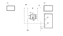
- FIG. 4 is a wiring diagram of the door lock actuator control circuit 26 according to the first embodiment.
- the door lock is locked or unlocked by connecting the locking wire 63 to the ground.
- the vehicle-mounted device 1 including the first internal relay 61 and the second internal relay 62 is connected between the door key locking switch 85 and the door key unlocking switch 86 and the door lock actuator 29.
- the door lock actuator 29 can be controlled via the first external relay 65 and the second external relay 75 by operating the first internal relay 61 and the second internal relay 62 of the vehicle-mounted device 1.
- the door lock actuator 29 is, for example, a direct current motor capable of rotating in the forward and reverse directions, and a lock line 63 and an unlock line 64 to which a 12 V power is always applied are connected to both ends of the DC motor.
- the lock wire 63 is connected to the terminal 70 of the first external relay.
- the unlocking wire 64 is connected to the terminal 80 of the second external relay 75.
- the switching contact 67 connected to the terminal 70 of the first external relay is mechanically biased toward the terminal 71 connected to the 12 V power supply at all times. When the coil 66 is energized, the contact 67 is switched to the terminal 72 connected to ground.
- the terminal 68 at one end of the coil 66 is connected to the 12 V power supply as the terminal 71 is.
- the terminal 69 at the other end of the coil 66 is connected to one end of a door key lock switch 85 which is a normally open switch, and the other end of the door key lock switch 85 is connected to the ground.
- a door key lock switch 85 which is a normally open switch
- One end of the door key locking switch 85 is connected to one end of a first internal relay which is a normally open switch, and the other end of the first internal relay 61 is connected to the ground.
- the switching contact 77 connected to the terminal 80 of the second external relay is mechanically biased toward the terminal 81 connected to the 12 V power supply at all times.
- the contact 77 is switched to the terminal 82 connected to ground.
- the terminal 78 at one end of the coil 76 is connected to the 12V power supply as the terminal 81 is.
- the terminal 79 at the other end of the coil 76 is connected to one end of a door key unlocking switch 86 which is a normally open switch, and the other end of the door key unlocking switch 86 is connected to the ground.
- One end of the door key unlocking switch 86 is connected to one end of the second internal relay which is a normally open switch, and the other end of the second internal relay 62 is connected to the ground.
- the remote control instructing unit 31 When an unlocking instruction is transmitted from the user terminal 37 to the user information managing unit 38, and the user information managing unit 38 determines that the unlocking instruction from the user terminal 37 is valid, the remote control instructing unit 31 is specified specifically. A door unlocking instruction to transmit an unlocking instruction to the vehicle 2 is transmitted. When receiving the door lock unlocking command from the user information management section 38, the remote control instructing section 31 transmits the unlocking command to the specific vehicle 2 to be reserved. In the on-vehicle device 1, when receiving the unlocking command from the remote control instructing unit 31, the conductive control is performed on the second internal relay 62, which is a normally open switch, for a predetermined time (for example, about 0.1 to 0.2 seconds).
- the coil 76 of the second external relay 75 is excited, whereby the switching contact 77 of the second external relay 75, which is normally energized by the 12 V power supply, is connected to the ground. It is switched to the terminal 82 side. Then, the unlocking wire 64 is connected to the ground through the terminal 80, the switching contact 77, and the terminal 82, so that one end of the direct current motor as the door lock actuator 29 becomes the ground potential, and the other end of the direct current motor Since 12 V is applied, the DC motor as the door lock actuator 29 is unlocked for a predetermined time (for example, about 0.1 to 0.2 seconds) in which the second internal relay 62 which is a normally open switch is conductive. Unlock the door lock by rotating in the direction.
- a predetermined time for example, about 0.1 to 0.2 seconds
- the second internal relay 62 which is a normally open switch, is turned on, the second internal relay 62 is opened, so the switching contact 77 of the second external relay 75 is connected to the 12V power supply. Since the 12V power is applied to both ends of the DC motor as the door lock actuator 29 by being biased by the terminal 81, the DC motor stops its operation.
- the user information management unit 38 sends a locking instruction to the remote control instructing unit 31 to transmit the locking instruction to the specific vehicle 2. Send an instruction.
- the remote control instructing unit 31 receives the door lock locking instruction from the user information management unit 38, the remote control instructing unit 31 transmits the locking instruction to the specific vehicle 2.
- the on-vehicle unit 1 conducts the conduction control of the first internal relay 61 which is a normally open switch for a predetermined time (for example, about 0.1 to 0.2 seconds).
- the coil 66 of the first external relay 65 is excited, whereby the switching contact 67 of the first external relay 65, which is normally energized by the 12 V power supply, is connected to the ground. It is switched to the terminal 72 side. Then, the lock wire 63 is connected to the ground via the terminal 70, the switching contact 67, and the terminal 72, so that the other end of the DC motor as the door lock actuator 29 is at the ground potential, and 12 V at one end of the DC motor. Is applied, the DC motor as the door lock actuator 29 has the above-mentioned solution only for a predetermined time (for example, about 0.1 to 0.2 seconds) in which the first internal relay 61 which is a normally open switch is conductive.
- a predetermined time for example, about 0.1 to 0.2 seconds
- the door lock is locked by rotating in the locking direction opposite to the locking direction.
- the first internal relay 61 which is a normally open switch, is turned on
- the first internal relay 61 is opened, so the switching contact 67 of the first external relay 65 is connected to the 12V power supply. Since the 12V power is applied to both ends of the DC motor as the door lock actuator 29 by being biased by the terminal 71, the DC motor stops its operation.
- the vehicle-mounted device 1 collects vehicle information at predetermined intervals, for example, every 30 seconds, or when a specific event occurs such as turning on the vehicle power, or both, and transmits the vehicle information to the server 3.
- vehicle information at this time information of power supply input from the external battery 21 detected by the power supply input detection unit 16, information of the traveling state identification line (ACC line, IG line) detected by the IGN input detection unit 17,
- the server 3 grasps the operation status of the vehicle based on the vehicle information.
- the vehicle-mounted device 1 receives an engine start relay control command from the server 3, the control value is stored in the memory 13, and the engine start external relay 20 is controlled to be in a state corresponding to the value.
- the "vehicle information interlocking control means" includes the CPU 11, the memory 13, the IGN input detection unit 17, and the engine start relay input / output 18, and when switching the engine start external relay 20, the power of the vehicle is turned on as described later. In consideration of the off switching timing, it is determined whether to adopt the engine start relay control command or not (when ignoring the engine start relay control command).
- the power on / off can be detected, for example, by the information of the traveling state identification line (ACC line, IG line) detected by the IGN input detection unit 17, eg, information indicating the on / off state of the engine. To detect.
- the traveling state identification line ACC line, IG line
- FIG. 5A shows the case where the engine start control line is a single vehicle type
- FIG. 5B shows the case where the engine start control line is a two vehicle type.
- the relay value of relay A is "0" when open and "1" when closed.
- the engine start external relay control value has two types of "00" and "01". When the engine start external relay control value is "00”, the status is startable (normal), and the vehicle state is startable. On the other hand, when the engine start external relay control value is "01", the status is in the start impossible state and the vehicle state is in the start impossible.
- the engine start external relay control values are four types of "00", “01”, “10” and "11".
- the engine start external relay control value is "00"
- the status is startable (normal), and the vehicle state is startable.
- the engine start external relay control value is "01”
- the status is an unintended value and the vehicle state can be started.
- the engine start external relay control value is "10”
- the status is an unintended value and the vehicle state can be started.
- the engine start external relay control value is "11" the status is in the start impossible state, and the vehicle state is in the start impossible.
- the "engine start relay monitoring unit” includes the CPU 11, the memory 13, and the engine start relay input / output 18, and as described later, the relay when the engine start external relay control value is originally in the startable state due to the malfunction of the firmware.
- the state is monitored, and when the relay state is other than the startable state by the monitoring, the relay state is the startable state, that is, the engine start external relay control value is set to "00", and the engine start external relay 20 is started. Make it possible.
- the engine start external relay 20 can select normally open and normally closed by changing the connection state.
- 41 is a coil of an electromagnet
- 42 is a switch
- 43 and 44 are terminals on the engine start relay input / output 18 side
- 45 is one terminal on an engine start control line (ST line) side
- 46 is a normally closed terminal
- 47 is normally open It is a terminal.
- the switch 42 is biased toward the normally closed terminal 46 by a spring, so that the switch 42 is in contact with the normally closed terminal 46 when the coil 41 is not energized.
- the switch 42 is attracted to the electromagnet and contacts the normally open terminal 47.
- At least one of the power input detection unit 16, the IGN input detection unit 17, the engine start relay input / output 18, and the GPS input / output unit 19 is provided with means (not shown) for detecting disconnection or withdrawal of wiring. It is done.
- a means for detecting the cutting or drawing of the wiring there can be used, for example, a known means of utilizing the voltage change of the wiring accompanying the cutting or drawing of the wiring as disclosed in Patent Document 2.
- the power input detection unit 16 When the power input detection unit 16 does not detect the power input from the external battery 21, it can also be determined that the wiring between the power input detection unit 16 and the external battery 21 is disconnected or pulled out. The removal of the vehicle-mounted device can also be detected based on the disconnection or withdrawal of these wires. When disconnection or removal of wiring is detected, control is made to either make the engine start external relay 20 non-startable (open) or startable (close) as described later. Let's decide.
- the engine start external relay 20 is controlled as described above, and the abnormality is notified to the server 3 via the wireless communication module 12.
- the server 3 receives the notification of the abnormality, the server 3 immediately notifies the administrator.
- the administrator contacts the user to confirm the occurrence of the theft and, as necessary, notifies the police of the theft of the vehicle.
- the vehicle-mounted device 1 makes an alarm sound by means of an alarm (not shown) mounted on the vehicle-mounted device 1 while notifying the abnormality.
- the vehicle-mounted device 1 can be connected to the input terminals of these control circuits so that an alarm can be issued using a horn, a headlamp, a blinker, a hazard lamp, etc. of the vehicle. It can also be wired to input the output signal of the alarm output of
- the vehicle-mounted device 1 is further provided with a failure detection means, and the failure detection means detects a failure of the vehicle-mounted device 1
- the failure of the vehicle-mounted device 1 may be notified to the server via the wireless communication module 12.
- the server 3 receives the notification of the failure of the in-vehicle device 1, the server notifies the administrator of the occurrence of the failure, and the administrator who receives the notification contacts the user of the corresponding vehicle to Arrange to repair or replace.
- the vehicle in the case of an emergency such as (3) as removal from the vehicle 2 of the vehicle-mounted device 1, for example, when transportation of a sudden sick person is assumed, the vehicle can be used in such a case Therefore, it is desirable to make the vehicle startable state, so the engine start external relay 20 can be started (closed) even when a normally closed type is adopted as the engine start external relay 20 and disconnection or removal of wiring is detected. It is good to decide in advance to control it.
- the vehicle-mounted device 1 can operate in a stand-alone fail-safe manner even when there is no radio wave condition and there is no engine start relay control command from the server 3. For example, it is possible to avoid a situation in which the vehicle can not be started at a place where the radio wave condition is bad and the engine start relay control command corresponding to the start enable information can not be received.
- the on-board unit repeats communication retry and tries to establish communication. If communication can not be established even if it is continuously retried a predetermined number of times, for example, 20 times or more, it is determined that communication is not possible, and if the state of the engine start external relay 20 is the start impossible state, the state is switched to the startable state.
- the server 3 can not transmit the engine start relay control signal to be changed to the startable state, so it is possible to avoid the situation where the vehicle is left unstartable. Whether to adopt the process of switching the vehicle to the startable state when communication can not be made can be switched at the time of shipment of the vehicle or the like.
- ⁇ About power saving mode> When the engine of the internal combustion engine vehicle is off, after a predetermined time, for example, 10 minutes, has elapsed since the engine was turned off, the on-vehicle device shifts to the power saving mode to prevent the power consumption of the external battery 21. Stop all but minimal functionality such as power management.
- the power input detection unit 16, the IGN input detection unit 17, the engine start relay input / output 18 and the clocking circuit (not shown) are always activated, but the other circuits are in a stopped state.
- the on-vehicle device 1 is not communicating with the server 3.
- the IGN input detection unit 17 detects the on state of the engine (ACC on or IG on), and the timer circuit is predetermined.
- the time is measured (for example, every one hour)
- the corresponding circuit constantly activated even in the power saving mode interrupts the CPU and switches the on-vehicle device 1 from the power saving mode to the normal mode. Further, since power is always supplied to the engine start relay input / output even in the power saving mode, the state of the engine start external relay 20 can be always maintained.
- the vehicle-mounted device 1 collects vehicle information at a predetermined cycle, for example, every 30 seconds in the normal mode, or when a specific event occurs such as turning on the vehicle power, or both. Send the vehicle information.
- the corresponding circuit that is always activated interrupts the CPU and switches the on-board unit 1 from the power saving mode to the normal mode, the on-board unit 1 is used as a starting point to communicate with the server 3 Receive and transmit vehicle information.
- the vehicle-mounted device 1 In the normal mode, in addition to the communication from the vehicle-mounted device 1, communication from the server 3 is possible, and the vehicle-mounted device 1 can receive information such as an engine start relay control command.
- the radio wave condition is bad, communication may be repeated several times, for example, about 5 times, before establishing communication.
- the on-vehicle unit 1 can operate in a stand-alone mode since the on-vehicle unit 1 stores the engine start relay control command received from the server 3 by the latest communication. It is possible. Moreover, since the vehicle-mounted device 1 stores the collected vehicle information in the memory, when the communication line is recovered, they can be collectively transmitted to the server 3. It should be noted that if the radio wave condition is bad, the engine start relay control command corresponding to the unstartable state may be not transmitted or received. In this case, since the radio wave condition is bad, from the unstartable state It is possible to avoid the inconvenience of not being able to change to the startable state.
- the memory 13 includes four processing units including a communication unit 50, an engine start relay control unit 51, an engine start relay monitoring unit 55, and an engine interlock control unit 57.
- the engine start relay control unit 51 includes an engine start relay set value 52, a vehicle type start disable relay value 53, and a vehicle type startable relay value 54
- the engine start relay monitoring unit 55 includes an engine start relay monitoring execution flag 56
- the engine interlock control unit 57 includes a relay change prohibition period 58, an engine stop time 59, and an engine state reevaluation period.
- the communication unit 50 is a data area for communication with the server 3. It is used to transmit vehicle information to the server 3 and receive an engine start relay control command from the server 3 via the wireless communication module 12.
- the engine start relay control unit is a data area for changing the engine start external relay 20 to a state corresponding to the relay value given by the engine start relay control command from the server 3.
- the engine start relay monitoring unit 55 is in a state where the relay state should be in the startable state, that is, the initial state or the state from the server 3 based on the relay state values of the start impossible state / startable state set as described later.
- the state of the engine start external relay 20 is periodically monitored, and as a result of this monitoring, the relay state of the engine start external relay 20 other than the startable state If it is, change it to bootable state.
- the engine interlock control unit 57 receives an engine start relay control command from the server 3 and ignores the engine start relay control command when the engine has been on for the past X minutes (for example, 2 minutes), If it is detected that the engine is on within Y seconds (for example, 5 seconds) after the execution of the engine start relay control command to the start impossible state, the engine start relay is changed to the startable state.
- the vehicle-mounted device 1 is switched to the power saving mode to reduce power consumption.
- the IGN input detection unit 17 turns on the engine from the traveling state identification line (ACC line, IG line) 22 It detects that the state has been entered, and interrupts the CPU 11 to switch the vehicle-mounted device 1 to the normal mode.
- the server 3 recognizes that the vehicle-mounted device 1 has been switched to the normal mode, when the radio wave condition is good, it is about 1 minute, and when the radio wave condition is bad and communication needs to be repeated about 5 times, 1 minute 30 seconds It takes a degree.
- the engine start relay control command instructing switching to the start impossible state for a certain period of time after the power of the vehicle is turned off, the power of the vehicle is turned off immediately after the power is turned off. Even when the power is turned on, it is possible to prevent the vehicle from being inadvertently switched to the unbootable state.
- the vehicle while loading and unloading the luggage from the trunk and the seat in the parking lot, the vehicle is stopped at a position slightly offset from the parking space and the power of the vehicle is turned off. In the case where the vehicle is put back into the parking space by turning on, it is possible to prevent the vehicle from being inadvertently switched to the non-startable state. Conversely, if X minutes are too long, the vehicle may not be able to be switched to the unstartable state, so if the engine has been turned on during the past two minutes, the engine is started We decided to ignore the relay control command. Therefore, the amount of X can be appropriately determined according to the specific performance of the server 3 and the like.
- the on-vehicle device 1 receives the engine start relay control command while the power of the vehicle is on, it does not receive the engine start relay control command in consideration of safety (ignoring the engine start relay control command). While the power of the vehicle is on, since the user is moving by the vehicle, for example, the reception of the engine start relay control command for changing the vehicle to the unstartable state is delayed because the radio wave condition is bad, etc. , Prevents the vehicle from becoming unbootable. On the other hand, it takes about three seconds after the vehicle is actually started until the vehicle-mounted device 1 recognizes the start of the vehicle.
- the vehicle-mounted device 1 determines that the vehicle is not started, and adopts the engine start relay control command, and the vehicle starts. There is a situation where the vehicle can be switched to the unbootable state despite the As described later, when the ignition switch is a push type, there are a method of disabling the push button and a method of activating an immobilizer (cutting a line for authentication) as methods of disabling activation. In the case of disabling the push button, there is a problem that the engine can not be disconnected if it is switched to the non-startable state during the three seconds.
- the engine start relay setting value 52 is a relay value corresponding to the current state of the engine start external relay 20.
- the vehicle type start disabling relay value 53 is a setting value for each vehicle type corresponding to the state of the engine start external relay 20 that sets the vehicle in the start disabling state.
- the vehicle type startable relay value 54 is a set value for each vehicle type corresponding to the state of the engine start external relay 20 that makes the vehicle startable.
- the engine start relay monitoring execution flag 56 is a flag that determines whether or not to execute the monitoring of the engine start external relay 20, and is in the initial state (when the vehicle is shipped) or the last engine start relay control from the server 3. Turns on when the command is a change to the startable state.
- the relay change prohibition period is a period (X minutes, for example, 2 minutes) in which the change of the engine start external relay 20 is prohibited after the engine is stopped.
- the engine stop time is the time when the engine stop was detected last time.
- the engine state reevaluation period is a period (Y seconds, for example, 5 seconds) in which the on state of the engine is reevaluated after control to the unstartable state.
- each vehicle type start relay value 53 and each vehicle type startable relay value 54 can be stored for each vehicle type start relay value 53 and each vehicle type startable relay value 54, or a plurality of vehicle model values are stored, and the vehicle model of the vehicle can be stored. It may be selected according to In addition, the car-type-not-startable relay value 53 and the car-type-startable relay value 54 may be set from the console input / output 14 or may be set from the server 3, but failsafe due to noise From the viewpoint, it is desirable to set from the server 3.
- the process proceeds to S16, the communication unit is called, the engine start relay state change completion is notified to the server 3, and the engine start relay control unit processing is ended in S17.
- the engine start relay control unit 51 is called and started by S25 of the engine start relay monitoring unit 55 of FIG. 9 described later and S36 of the engine interlock control unit 57 of FIG. 8 described later.
- the engine start relay monitoring execution flag 56 is a flag that determines whether to execute the monitoring of the engine start external relay 20, and is in the initial state (when the vehicle is shipped) or the last from the server 3 Is turned on when the engine start relay control command is changed to the startable state. If the determination in S22 is YES, the process proceeds to S23, and after acquiring the relay state of the engine start external relay 20, the process proceeds to S24.
- the process proceeds to S26, and the engine start relay monitoring unit process ends.
- S24 it is determined whether the relay value acquired in S23 is a value other than the startable relay value for each vehicle type 54. If Yes, the process proceeds to S25, the engine start relay control unit 51 is called, and the engine start relay After overwriting the setting value 52 with the vehicle type startable relay value 54 corresponding to the startable state, the state of the engine start external relay 20 is changed to the state corresponding to the vehicle type startable relay value 54, and then the process proceeds to S26. End the engine start relay monitoring process. On the other hand, if the determination in S24 is No, the process directly proceeds to S26, and the engine start relay monitoring unit processing is ended.
- the operation of the engine start relay monitoring unit is performed periodically, for example, every 30 seconds in the normal mode and every one hour in the power saving mode. Due to the operation of the engine start relay monitoring unit, the memory 13 is rewritten to a value different from the original value due to the malfunction of the firmware of the on-vehicle unit when it can be originally started (when the engine start relay monitoring execution flag is on). Even if the vehicle has been shut down, the vehicle can not be started up unintentionally by controlling the engine start external relay 20 so that the vehicle can always be started up, preventing the use of the legitimate vehicle.
- the vehicle is always on when the engine start relay monitoring execution flag 56 is on.
- the engine start external relay 20 By controlling the engine start external relay 20 so as to be in the startable state, the vehicle can be maintained in the startable state.
- the process proceeds to S32, receives an engine start relay control command through the communication unit 50, and then proceeds to S33 to determine whether the current engine state is off. If the determination in S33 is YES, the process proceeds to S34. In S34, it is determined whether the difference between the current time and the engine stop time is equal to or longer than the relay change prohibition period 58 (X minutes). If No in S33 or No in S34, the process proceeds to S35, the communication unit 50 is called to notify the server 3 of neglecting the engine start relay control command, and then in S41, the engine interlocking control unit End the process.
- the process proceeds to S36, the engine start relay control unit 51 is called, the state of the engine start external relay 20 is changed to a state corresponding to the engine start relay control command, and the process proceeds to S37.
- the process proceeds to S38, and in S38, the executed engine start relay control command is a change to the start impossible state, and the current engine state is on. Determine if it is or not. If the determination in S38 is YES, the process proceeds to S39, in which the engine start relay control unit 51 is called and the state of the engine start external relay 20 is changed to a state corresponding to the startable relay value 54 for each vehicle type.
- the operation of the engine interlocking control unit 57 is performed periodically, for example, every 30 seconds in the normal mode and every one hour in the power saving mode.
- the communication unit 50 is called to notify the server 3 of neglecting the engine start relay control command, but when the server 3 receives that this engine start relay control command is ignored, the server 3 is displayed in S16 of FIG.
- the engine start relay control command is repeatedly transmitted until the state change completion of the engine start external relay 20 is notified.
- FIG. 11 is an overall view of a vehicle door lock locking and unlocking system according to a second embodiment.
- the same reference numerals as in FIGS. 1 to 10 denote the same parts, and a description thereof will be omitted.
- the lock command and the unlock command are transmitted from the user terminal 37 to the in-vehicle device 1 via the server 3, but in the second embodiment, the user terminal 37 directly transmits the lock instruction and the unlock instruction to the in-vehicle device 1.
- the embodiment differs from the embodiment in that the locking command and the unlocking command are transmitted.
- a flow from reservation of the specific vehicle 2 from the user terminal 37 to unlocking the door lock of the specific vehicle 2 will be described.
- a plurality of sales offices (such as a manned or unmanned parking lot) are registered as parking lots that the user receives and returns vehicles.
- the user information management system manages vehicle reservation status, dispatch status for each sales office, and the like.
- the user communicates with the user information management unit 38 using the user terminal 37 in order to reserve the specific vehicle 2 to use the period (the date and time of start of use and the date of return) And time), specify the sales office to receive the vehicle, the sales office to return the vehicle.
- the user information management unit 38 confirms whether or not the vehicle allocation is possible with the content designated by the user, and sends back to the user terminal 37 whether or not the reservation is possible.
- the user information management unit 38 requests the user terminal to settle the usage fee by card settlement or the like.
- the reservation is confirmed.
- the user information management unit 38 transmits the reservation information to the user terminal.
- the user terminal 37 is notified that the reservation is impossible.
- the user information management unit 38 can present a plurality of different reservation-ready conditions close to the previously designated content.
- the user information management unit 38 transmits the door lock key information and the vehicle identification information (for example, the place of the sales office, the number of the license plate, etc.) to the user terminal 37. And receive vehicle number information.
- the timing at which the user terminal 37 receives the door lock key information from the user information management unit 38 can be, for example, 10 minutes before the start time of the reservation, but the present invention is not limited to this, and after the reservation is determined , Any time before the reservation start time can be.
- the user information management unit 38 transmits the door lock key information to the user terminal 37 (for example, 10 minutes before the reservation start time) or at a time slightly earlier than this timing (for example, 15 minutes before the reservation start time) Via the remote control instructing unit 31, door lock key information corresponding to the one transmitted to the user terminal 37 is transmitted to a specific vehicle to be reserved using the wireless communication network 34.
- reservation information such as a reception office, a reception office, a return office, etc. can also be transmitted to the vehicle-mounted device 1.
- the user opens the door from the user terminal 37 to the on-vehicle device 1 near the specific vehicle that matches the reserved vehicle identification information at the reserved sales office. Send an unlock command using lock key information.
- the distance between the user terminal 37 and the reservation vehicle 2 at the time of this communication is within the area of the short distance wireless communication from the user terminal 37 to the on-vehicle device 1 and is sufficiently close for the user to confirm the condition of the reservation vehicle It is desirable to set the distance. Examples of this short distance wireless communication include Bluetooth (registered trademark), ZigBee (registered trademark), infrared communication, and FRID, but the present invention is not limited to this, and any kind of short distance wireless communication may be used. It includes communication.
- Each of the user terminal 37 and the vehicle-mounted device 1 incorporates a transmitter / receiver for specific short distance wireless communication.
- the on-vehicle device 1 authenticates this unlocking command.
- the internal relay 25 is controlled to conduct for a predetermined time (for example, about 0.1 to 0.2 seconds) to control the external relay 28.
- the external relay 28 is switched, the door lock actuator 29 is driven and the door lock 4 is unlocked.
- the door locks 4 of all the doors of a specific vehicle can be unlocked, but the present invention is not limited to this, for example, only the door lock 4 of the driver's seat door is released. It can be locked or the door lock 4 of the front and rear doors on the driver's side can be unlocked.
- the vehicle-mounted device 1 When the vehicle-mounted device 1 receives the reservation information such as the reservation period, the vehicle-mounted device 1 is in a state where the reservation vehicle 2 is in the receiving office designated at the time of reservation, although it is determined that the unlocking command received from the user terminal 37 is a little earlier than the start time of the reservation (for example, 10 minutes ago) until the end time of the reservation, a time earlier than the reservation time (for example, It is judged that the unlocking command after the end of the reservation time or the time earlier than 10 minutes is invalid. When the vehicle-mounted device 1 determines that the unlocking command is invalid for the reservation time, a message to the effect that the reservation time is out is transmitted to the user terminal 37 to notify the user. It is also good.
- operation keys including mechanical keys and smart keys are stored. For this reason, once the door lock is unlocked by the unlocking command, the reservation vehicle 2 can be used later by using the normal operation key.
- the flow from when the use of the reservation vehicle 2 ends to when the reservation vehicle 2 is returned to the parking lot of the sales office specified at the time of reservation will be described.
- the engine is stopped and the vehicle is turned off, and then the operation key is stored in a predetermined place in the vehicle.
- the user terminal 37 transmits a locking instruction to the on-vehicle device 1.
- the external relay 28 is controlled by conducting control of the internal relay 25 for a predetermined time (for example, about 0.1 to 0.2 seconds) by authenticating the door lock key information included in the locking command. .
- the door lock actuator 29 is driven and the door lock 4 is locked.
- the door locks 4 of all the doors of a specific vehicle can be locked. In addition, it can be arbitrarily determined which door is locked or not locked.
- the user information management unit 38 When the user information management unit 38 detects that the vehicle 2 is parked at the office scheduled for return registered at the time of reservation based on the vehicle 2 position information from the vehicle information collection unit 32, the user information management unit 38 A message prompting a lock command for the on-vehicle device 1 from the user terminal 37 is displayed. Finally, when the locking of the reserved vehicle 2 is completed, it is considered that the return of the reserved vehicle 2 is completed, and the user information management unit 38 transmits a message to the user terminal 37 to the effect that the return procedure is completed. . If the vehicle-mounted device 1 can detect whether it is a lock by the operation key or a lock by the vehicle-mounted device 1, the user information management unit 38 indicates that the return is completed based on the information of the vehicle information collection unit 32. Can be grasped in
- the position of the reservation vehicle 2 can be grasped by the GPS of the on-vehicle device 1.
- reservation information such as a reception period, a reception office, a return office, etc.
- the on-board unit 1 transmits a message to the user terminal 37 indicating that the parking position is different from the return location.
- the vehicle-mounted device 1 can also determine whether or not the lockable state is available based on the acquired vehicle information. For example, when the engine is being started, the locking instruction is invalidated, and a message to the effect that locking is not possible is transmitted to the user terminal via the user information management unit 38 to warn the user. Prompt.
- the locking instruction and the unlocking instruction for the same vehicle from the same user terminal 37 are invalidated after the end of the reservation period.
- the same door lock key information is valid during the extension period.
- a car sharing office (a manned or unmanned parking lot or the like) be a point where the radio wave condition of the communication of the wireless communication network 34 and the user terminal 37 is good. This is because the communication between the user terminal 37 and the server 3 or the communication between the server 3 and the vehicle-mounted device 1 is disturbed when the radio wave condition is bad, and door lock key information or It is because reservation information etc. may not be transmitted appropriately and problems may occur in the locking, unlocking, and information transmission to the user terminal of the specific vehicle 2.
- the on-board unit 1 may be able to receive the lock command and the unlock command from the server 3.
- the server 3 can be authenticated if the user's authentication and reservation contents can be confirmed using another communication means.
- car sharing system has been described here, the same system can be applied to car rental. Furthermore, the locking and unlocking of the vehicle 2 from the user terminal 37 via the server 3 can be applied to car leasing and the like.
- FIG. 12 is a wiring diagram of the door lock actuator control circuit 26A according to the third embodiment.
- the door lock actuator control circuit 26A There are the following five types of door lock actuator control circuit 26, depending on the 12V power supply and the connection of the ground.
- Negative control Normally, lock and unlock lines are 12V power.
- Plus control 1 Normally, the lock and unlock lines are grounded.
- Plus Control 2 Normally, the lock and unlock lines are open.
- Minus plus control earth when locking, 12V power when unlocking
- Plus / minus control (12V power supply when locking, earthing when unlocking
- the first embodiment corresponds to (1) minus control
- the third embodiment corresponds to (2) plus control 1.
- the fourth to seventh embodiments described later corresponds to (3) plus control 2
- the fifth embodiment is a modification of (3) plus control 2
- the seventh embodiment corresponds to (5) plus / minus control.
- the door lock is locked or unlocked by connecting the locking wire 63 to a 12V power supply.
- the vehicle-mounted device 1 including the first internal relay 61 and the second internal relay 62 is connected between the door key locking switch 85 and the door key unlocking switch 86 and the door lock actuator 29.
- the door lock actuator 29 can be controlled via the first external relay 65 and the second external relay 75 by operating the first internal relay 61 and the second internal relay 62 of the vehicle-mounted device 1.
- the door lock actuator 29 is, for example, a direct current motor capable of rotating in the forward and reverse directions, and a locking wire 63 and an unlocking wire 64, which are always connected to the ground, are connected to both ends of the DC motor.
- the lock wire 63 is connected to the terminal 70 of the first external relay.
- the unlocking wire 64 is connected to the terminal 80 of the second external relay 75.
- the switching contact 67 connected to the terminal 70 of the first external relay is mechanically biased toward the terminal 71 which is always connected to the ground. When the coil 66 is energized, the contact 67 is switched to the terminal 72 connected to the 12V power supply.
- the terminal 68 at one end of the coil 66 is connected to the same ground as the terminal 71.
- the terminal 69 at the other end of the coil 66 is connected to one end of a door key lock switch 85 which is a normally open switch, and the other end of the door key lock switch 85 is connected to a 12V power supply.
- One end of the door key locking switch 85 is connected to one end of a first internal relay 61 which is a normally open switch, and the other end of the first internal relay 61 is connected to a 12V power supply.
- the switching contact 77 connected to the terminal 80 of the second external relay is mechanically biased toward the terminal 81 which is always connected to the ground.
- the switching contact 77 is switched to the terminal 82 connected to the 12V power supply.
- the terminal 78 at one end of the coil 76 is connected to the same ground as the terminal 81.
- the terminal 79 at the other end of the coil 76 is connected to one end of a door key unlocking switch 86 which is a normally open switch, and the other end of the door key unlocking switch 86 is connected to a 12V power supply.
- One end of the door key unlocking switch 86 is connected to one end of a second internal relay which is a normally open switch, and the other end of the second internal relay 62 is connected to a 12V power supply.
- the user information managing unit 38 determines that the unlocking instruction from the user terminal 37 is valid.
- a door unlocking instruction to transmit the unlocking instruction to the specific vehicle 2 is transmitted.
- the remote control instructing section 31 transmits the unlocking command to the specific vehicle 2 to be reserved.
- the conductive control is performed on the second internal relay 62, which is a normally open switch, for a predetermined time (for example, about 0.1 to 0.2 seconds).
- the coil 76 of the second external relay 75 is excited, whereby the switching contact 77 of the second external relay 75 is normally biased to the terminal 81 connected to the ground. Is switched to the terminal 82 side connected to the 12V power supply. Then, the unlocking wire 64 is connected to the 12 V power supply via the terminal 80, the switching contact 77, and the terminal 82, whereby 12 V is applied to one end of the DC motor as the door lock actuator 29. Since the end is at the ground potential, the DC motor as the door lock actuator 29 is unlocked for a predetermined time (for example, about 0.1 to 0.2 seconds) in which the second internal relay 62 which is a normally open switch is conductive. Unlock the door lock by rotating in the direction.
- a predetermined time for example, about 0.1 to 0.2 seconds
- the switching contact 77 of the second external relay 75 is connected to ground. Since the DC motor 81 is biased to 81 and both ends of the DC motor as the door lock actuator 29 are at the ground potential, the DC motor stops its operation.
- the user information management unit 38 sends a locking instruction to the remote control instructing unit 31 to transmit the locking instruction to the specific vehicle 2.
- the remote control instructing unit 31 receives the door lock locking instruction from the user information management unit 38
- the remote control instructing unit 31 transmits the locking instruction to the specific vehicle 2.
- the on-vehicle unit 1 conducts the conduction control of the first internal relay 61 which is a normally open switch for a predetermined time (for example, about 0.1 to 0.2 seconds).
- the coil 66 of the first external relay 65 is excited, whereby the switching contact 67 of the first external relay 65, which is normally biased to the ground, is connected to the 12V power source. It is switched to the terminal 72 side. Then, the lock wire 63 is connected to the 12 V power supply via the terminal 70, the switching contact 67, and the terminal 72, whereby 12 V is applied to the other end of the DC motor as the door lock actuator 29, and one end of the DC motor Is connected to the ground, the DC motor as the door lock actuator 29 is only for a predetermined time (for example, about 0.1 to 0.2 seconds) in which the first internal relay 61, which is a normally open switch, is conductive.
- a predetermined time for example, about 0.1 to 0.2 seconds
- the door lock is locked by rotating in the locking direction which is the opposite direction to the above-mentioned unlocking direction.
- the first internal relay 61 which is a normally open switch, is turned on
- the first internal relay 61 is opened, so the switching contact 67 of the first external relay 65 is a terminal connected to ground.
- the DC motor stops its operation.
- FIG. 13 is a wiring diagram of the door lock actuator control circuit 26B according to the fourth embodiment.
- the type of door lock actuator control circuit 26 corresponds to (3) plus control 2 described above.
- the vehicle-mounted device 1 including the first internal relay 61 and the second internal relay 62 is connected between the door key switch and the door lock actuator 29 via the first external relay 65B and the second external relay 75B, and the first internal Under the control of the relay 61B and the second internal relay 62B, the DC motor as the door lock actuator 29B is driven to lock and unlock the door lock.
- the user information managing unit 38 determines that the unlocking instruction from the user terminal 37 is valid. , Transmits a door lock unlocking command for transmitting the unlocking command to the specific vehicle 2.
- the remote control instructing section 31 transmits the unlocking command to the specific vehicle 2 to be reserved.
- the conductive control is performed on the second internal relay 62B, which is a normally open switch, for a predetermined time (for example, about 0.1 to 0.2 seconds).
- the switching contact 77B of the second external relay 75B is regulated by a 12V power supply.
- the second internal relay 62B When the second internal relay 62B is turned on, the coil 76B of the second external relay 75B is excited, whereby the switching contact 77B of the second external relay 75B, which is normally biased to the open terminal 82B, unlocks the wire 64B. Is switched to the terminal 81B connected to. Thereby, 12V is applied to the unlocking line 64B by the 12V power supply via the terminal 81B and the switching contact 77B.
- the DC motor as the door lock actuator 29 rotates in the unlocking direction for a predetermined time (for example, about 0.1 to 0.2 seconds) in which the second internal relay 62B, which is a normally open switch, is conductive. Unlock the door lock.
- the second internal relay 62B which is a normally open switch, is turned on, the second internal relay 62B is opened, so the switching contact 77B of the second external relay 75B is biased to the open terminal 82B.
- the DC motor as the door lock actuator 29 stops its operation.
- the user information management unit 38 instructs the remote control instructing unit 31 to transmit a door lock locking instruction to transmit the locking instruction to the specific vehicle 2.
- Send When the remote control instructing unit 31 receives the door lock locking instruction from the user information management unit 38, the remote control instructing unit 31 transmits the locking instruction to the specific vehicle 2 to be reserved.
- the on-vehicle device 1 when receiving the lock command from the remote control instructing unit 31, the on-vehicle unit 1 conducts the conduction control of the first internal relay 61B, which is a normally open switch, for a predetermined time (for example, about 0.1 to 0.2 seconds).
- the switching contact 67B of the first external relay 65B is regulated by a 12V power supply.
- the coil 66B of the first external relay 65B is excited, whereby the switching contact 67B of the first external relay 65B, which is normally biased to the open terminal 72B, is connected to the lock wire 63B. It is switched to the connected terminal 71B.
- 12V is applied to the lock line 63B by the 12V power supply via the terminal 71B and the switching contact 67B.
- the DC motor as the door lock actuator 29 has the above-described unlocking direction only for a predetermined time (for example, about 0.1 to 0.2 seconds) in which the first internal relay 61B, which is a normally open switch, is conductive.
- the door lock is locked by rotating in the reverse locking direction.
- the first internal relay 61B which is a normally open switch, is turned on, the first internal relay 61B is opened, so the switching contact 67B of the first external relay 65B is biased to the open terminal 72B.
- the DC motor as the door lock actuator 29 stops its operation.
- FIG. 14 is a wiring diagram of the door lock actuator control circuit 26C according to the fifth embodiment.
- the type of the door lock actuator control circuit 26 is a modification of the (3) plus control 2 described above.
- the DC motor as the door lock actuator 29C is driven to lock and unlock the door lock.
- the first external relay 65C is connected to the lock line 63C so as to bypass it, and the original wiring of the bypassed portion of the lock line 63C is disconnected.
- the second external relay 75C is connected to the unlocking line 64C so as to bypass it, and the original wiring of the bypassed portion of the unlocking line 64C is disconnected.
- the vehicle-mounted device 1 including the first internal relay 61C and the second internal relay 62C is connected between the door key switch and the door lock actuator 29 via the first external relay 65C and the second external relay 75C, and the first internal Under the control of the relay 61C and the second internal relay 62C, the DC motor as the door lock actuator 29C is driven to lock and unlock the door lock.
- the user information managing unit 38 determines that the unlocking instruction from the user terminal 37 is valid.
- a door unlocking instruction to transmit the unlocking instruction to the specific vehicle 2 is transmitted.
- the remote control instructing section 31 transmits the unlocking command to the specific vehicle 2 to be reserved.
- the conductive control is performed on the second internal relay 62C, which is a normally open switch, for a predetermined time (for example, about 0.1 to 0.2 seconds).
- the terminal 80C, the switching contact 77C and the terminal 82C of the second external relay 75C always bypass the disconnected portion of the unlocking wire 64C.
- the second internal relay 62C which is a normally open switch, is controlled to conduct for a predetermined time (for example, about 0.1 to 0.2 seconds)
- the coil 76C of the second external relay 75C is excited and the switching contact 77C is connected to the 12V power supply Is switched to the terminal 81C.
- the 12V power supply is connected to the unlocking line 64C via the terminal 80C, the switching contact 77C and the terminal 81C, and 12V is applied.
- the DC motor as the door lock actuator 29C rotates in the unlocking direction for a predetermined time (for example, about 0.1 to 0.2 seconds) in which the second internal relay 62C, which is a normally open switch, is conductive. Unlock the door lock. After the predetermined time during which the second internal relay 62C, which is a normally open switch, is turned on, the second internal relay 62C is opened, so the switching contact 77C of the second external relay 75C is biased to the terminal 82C. In order to bypass the cut portion of the unlocking wire 64C, the DC motor as the door lock actuator 29 stops its operation.
- a predetermined time for example, about 0.1 to 0.2 seconds
- the second internal relay 62C which is a normally open switch
- the user information management unit 38 instructs the remote control instructing unit 31 to transmit a door lock locking instruction to transmit the locking instruction to the specific vehicle 2.
- Send When the remote control instructing unit 31 receives the door lock locking instruction from the user information management unit 38, the remote control instructing unit 31 transmits the locking instruction to the specific vehicle 2 to be reserved.
- the on-vehicle device 1 when receiving the lock command from the remote control instructing unit 31, the on-vehicle unit 1 conducts the conduction control of the first internal relay 61C, which is a normally open switch, for a predetermined time (for example, about 0.1 to 0.2 seconds).
- the terminal 70C, the switching contact 67C and the terminal 72C of the first external relay 65C always bypass the disconnected portion of the lock wire 63C.
- the first internal relay 61C which is a normally open switch, is controlled to conduct for a predetermined time (for example, about 0.1 to 0.2 seconds)
- the coil 66C of the first external relay 65C is excited and the switching contact 67C is connected to the 12V power supply
- the terminal 71C is switched.
- the 12V power source is connected to the lock line 63C via the terminal 70C, the switching contact 67C and the terminal 71C, and 12V is applied.
- the DC motor as the door lock actuator 29C has the above-described unlocking direction only for a predetermined time (for example, about 0.1 to 0.2 seconds) in which the first internal relay 61C, which is a normally open switch, is conductive.
- the door lock is locked by rotating in the reverse locking direction.
- the first internal relay 61C is opened, so the switching contact 67C of the first external relay 65C is biased to the terminal 72C.
- the DC motor as the door lock actuator 29 stops its operation in order to bypass the cut portion of the lock wire 63C.
- FIG. 15 is a wiring diagram of the door lock actuator control circuit 26D according to the sixth embodiment.
- the type of door lock actuator control circuit 26 corresponds to (4) minus plus control described above.
- the lock / unlock line 74D connected to the door lock relay unit 73D is connected to a vacuum pump unit which is a door lock actuator 29D.
- the lock / unlock line 74D is at ground potential when locked and is 12V power when unlocked.
- a series circuit of the first external relay 65D and the second external relay 75D is connected to bypass the locking and unlocking line 74D, and the original wiring of the bypassed portion of the locking and unlocking line 74D is cut.
- the vehicle-mounted device 1 including the first internal relay 61D and the second internal relay 62D is connected between the door key switch and the door lock actuator 29D via the first external relay 65D and the second external relay 75D. Under control of the first internal relay 61D and the second internal relay 62D, the vacuum pump unit as the door lock actuator 29D is driven to lock and unlock the door lock.
- the user information managing unit 38 determines that the unlocking instruction from the user terminal 37 is valid.
- a door unlocking instruction to transmit the unlocking instruction to the specific vehicle 2 is transmitted.
- the remote control instructing section 31 transmits the unlocking command to the specific vehicle 2 to be reserved.
- the on-vehicle device 1 when receiving the unlocking command from the remote control instructing unit 31, the on-vehicle unit 1 conducts the conduction control of the second internal relay 62D which is a normally open switch for a predetermined time.
- the switching contact 67D of the first external relay 65D is always biased to the terminal 72D connected to the locking and unlocking line.
- the switching contact 77D of the second external relay 75D is biased to the terminal 82D connected to the terminal 70D of the first external relay 65D. Therefore, normally, the cut portion of the locking / unlocking line 74D is bypassed through the terminal 72D, the switching contact 67D, the terminal 70D, the terminal 82D, the switching contact 77D and the terminal 80D.
- the second internal relay 62D which is a normally open switch, is conductively controlled for a predetermined time, the coil 76D of the second external relay 75D is excited, and the switching contact 77D is switched to the terminal 81D connected to the 12V power supply.
- the 12V power source is connected to the locking / unlocking line 74D via the terminal 80D, the switching contact 77D, and the terminal 81D, and 12V is applied.
- the vacuum pump unit as the door lock actuator 29D unlocks the door lock by being driven in the unlocking direction only for a predetermined time during which the second internal relay 62D, which is a normally open switch, is conducted. After the predetermined time during which the second internal relay 62D, which is a normally open switch, is turned on, the second internal relay 62D is opened, and hence the switching contact 77D of the second external relay 75D is biased to the terminal 82D. Since the cut portion of the locking / unlocking line 74D is bypassed by the series circuit of the first external relay 65D and the second external relay 75D, the operation of the vacuum pump unit as the door lock actuator 29D is stopped.
- the user information management unit 38 instructs the remote control instructing unit 31 to transmit a door lock locking instruction to transmit the locking instruction to the specific vehicle 2.
- Send When the remote control instructing unit 31 receives the door lock locking instruction from the user information management unit 38, the remote control instructing unit 31 transmits the locking instruction to the specific vehicle 2 to be reserved.
- the on-vehicle device 1 when receiving the locking command from the remote control instructing unit 31, the on-vehicle unit 1 conducts the conduction control of the first internal relay 61 ⁇ / b> D, which is a normally open switch, for a predetermined time.
- the switching contact 67D of the first external relay 65D is always biased by the terminal 72D connected to the locking / unlocking line 74D.
- the switching contact 77D of the second external relay 75D is biased to the terminal 82D connected to the terminal 70D of the first external relay 65D. Therefore, normally, the cut portion of the locking / unlocking line 74D is bypassed through the terminal 72D, the switching contact 67D, the terminal 70D, the terminal 82D, the switching contact 77D and the terminal 80D.
- the first internal relay 61D which is a normally open switch, is conductively controlled for a predetermined time, the coil 66D of the first external relay 65D is excited, and the switching contact 67D is switched to the terminal 71D connected to the ground.
- the locking / unlocking line 74D is connected to the ground via the terminal 80D, the switching contact 77D, the terminal 82D, the terminal 70D, the switching contact 67D, and the terminal 71D.
- the vacuum pump unit as the door lock actuator 29D is driven in the locking direction opposite to the above-mentioned unlocking direction only for a predetermined time during which the first internal relay 61D, which is a normally open switch, is conducted. , Lock the door lock. After the predetermined time for which the first internal relay 61D, which is a normally open switch, is turned on has passed, the first internal relay 61D is opened, so the switching contact 67D of the first external relay 65D is biased to the terminal 72D. Since the cut portion of the locking / unlocking line 74D is bypassed by the series circuit of the first external relay 65D and the second external relay 75D, the operation of the vacuum pump unit as the door lock actuator 29D is stopped.
- FIG. 16 is a wiring diagram of the door lock actuator control circuit 26E according to the seventh embodiment.
- the type of door lock actuator control circuit 26 corresponds to (5) plus / minus control described above.
- the lock / unlock line 74E connected to the door lock switch 83E is connected to the central door lock module which is the door lock actuator 29E, and the lock / unlock line 74E is 12 V of the power supply voltage at the time of locking, and is at the ground potential .
- the first external relay 65E is connected to bypass the locking and unlocking line 74E, and the original wiring is disconnected at the bypassed portion of the locking and unlocking line 74E.
- the second internal relay 62E of the vehicle-mounted device 1 is connected between the door lock switch 83E and the door lock actuator 29E, and the first internal relay 61E of the vehicle-mounted device 1 is connected via the first external relay 65E. Under control of the first internal relay 61E and the second internal relay 62E, the central door lock module as the door lock actuator 29E is driven to lock and unlock the door lock.
- the user information managing unit 38 determines that the unlocking instruction from the user terminal 37 is valid. , Transmits a door lock unlocking command for transmitting the unlocking command to the specific vehicle 2.
- the remote control instructing section 31 transmits the unlocking command to the specific vehicle 2 to be reserved.
- the on-vehicle device 1 when receiving the unlocking command from the remote control instructing unit 31, the on-vehicle unit 1 conducts the conduction control of the second internal relay 62E which is a normally open switch for a predetermined time.
- One end of the second internal relay 62E is connected to the ground, and the other end is connected to the locking and unlocking wire 74E.
- the second internal relay 62E which is a normally open switch, is controlled to conduct only for a predetermined time, the locking / unlocking line 74E is at the ground potential, so the central door lock module is driven in the unlocking direction and the door lock is unlocked. Ru.
- the user information management unit 38 instructs the remote control instructing unit 31 to transmit a door lock locking instruction to transmit the locking instruction to the specific vehicle 2.
- Send When the remote control instructing unit 31 receives the door lock locking instruction from the user information management unit 38, the remote control instructing unit 31 transmits the locking instruction to the specific vehicle 2 to be reserved.
- the on-vehicle device 1 when receiving the locking command from the remote control instructing unit 31, the on-vehicle unit 1 performs conduction control of the first internal relay 61 ⁇ / b> E which is a normally open switch for a predetermined time.
- the switching contact 67E of the first external relay 65E is always biased to the terminal 72E, the portion where the locking / unlocking line 74E is always disconnected is via the terminal 70E, the switching contact 67E and the terminal 72E. It is bypassed.
- the first internal relay 61E which is a normally open switch, is controlled to conduct for a predetermined time, the coil 66E of the first external relay 65E is excited, and the switching contact 67E is switched to the terminal 72E connected to the 12V power supply.
- the locking / unlocking wire 74E is connected to the 12V power supply via the terminal 70E, the switching contact 67E and the terminal 72E, and the 12V is applied, whereby the centralized door lock module as the door lock actuator 29E is normally open.
- the door lock is locked by driving the first internal relay 61E, which is a switch, in the locking direction opposite to the unlocking direction for a predetermined time during which the first internal relay 61E is turned on. After the predetermined time for which the first internal relay 61E, which is a normally open switch, is turned on has passed, the first internal relay 61E is opened, so the switching contact 67E of the first external relay 65E is biased to the terminal 72E. Since the cut portion of the lock / unlock line 74E is bypassed by the first external relay 65E, the operation of the centralized door lock module as the door lock actuator 29E is stopped.
- FIG. 17 is a diagram for explaining the control method of the unstartable state.
- FIG. 17 classifies vehicles into internal combustion engine vehicles, EV vehicles, parallel HEV vehicles, series HEV vehicles and series / parallel HEV vehicles as types of vehicles, and whether or not they are equipped with an immobilizer.
- the activation method is divided into a key type and a push type, and it is summarized which of the three methods of A method, B method and C method can be adopted as a control method of the non-startable state.
- the A method cuts the ST line
- the B method prohibits key authentication
- the C method invalidates the push button.
- the key type and the push type are divided into operation methods for starting power.
- the key type is one in which a key is inserted into a key cylinder to start power, and switching between OFF, ACC, IGN and START is performed.
- the push type is a smart key type system, in which power is turned on by pressing a power start push button.
- the definition of HEV vehicle is as follows.
- the parallel method is a method of driving wheels by a motor and an engine, and is a method of charging a battery by using a motor.
- the series method is a method in which an engine drives and drives a generator, and a motor drives a wheel.
- the series-parallel system is a system capable of driving the wheels by the motor and the engine and driving the generator by the engine to charge and drive the motor.
- the configuration of the vehicle-mounted device 1 has many parts in common with the one for internal combustion engine vehicles shown in FIG. 2 for EV vehicles and HEV vehicles, but there is no internal combustion engine in EV vehicles,
- the HEV vehicle is different from the case of the internal combustion engine vehicle in that there is a mode in which the vehicle can travel only by the motor.
- Method A is the method described in the first embodiment, and is a method of switching to the start impossible state by disconnecting the engine start control line (ST line) of the internal combustion engine by the engine start external relay 20 and applied to internal combustion engine vehicles it can.
- ST line engine start control line
- the engine start external relay 20 is inserted in the ST line, and the engine start external relay 20 is opened when the start is not possible, thereby blocking power supply to the cell motor, thereby preventing engine start. can do.
- Method B is a method adopted by vehicles equipped with an immobilizer.
- a unique ID code is recorded on an IC chip called a transponder embedded in a key, and the ID code of the transponder is authenticated by the ID code registered in the electronic control unit of the vehicle body, and the authentication is performed.
- It is a device that can start the engine only when it is established.
- the engine start external relay 20 is inserted into the signal line of the transponder side ID code received by the vehicle in the immobilizer from the transponder, or the signal line of the vehicle ID code in the immobilizer, and the engine can not be started.
- the start-up external relay 20 By opening the start-up external relay 20, the authentication of the ID code is not established, so the engine can not be started in the start-up impossible state.
- the engine start external relay 20 is used to make the start impossible state, but any means may be used as long as authentication of the ID code is not established in the start impossible state.
- electronic means may be used. Even when using electronic means, it is desirable that the engine start relay input / output 18 (see FIG. 2) can detect whether the start is impossible or the start is possible.
- the C method is a method adopted for a vehicle equipped with a push button for power start in the smart key type.
- smart key type vehicles there is no key cylinder for power start, and power is started by notifying the electronic control unit that the push button has been pressed.
- EV vehicles do not have a key type, and all are push types.
- the engine start external relay 20 is inserted in the push button wiring, and the engine start external relay 20 is opened in the start impossible state, and the power is not turned on even if the push button is operated in the start impossible state. .
- an example has been described in which the engine start external relay 20 is used to make the start impossible state.
- any means May be used, for example, electronic means may be used. Even when using electronic means, it is desirable that the engine start relay input / output 18 (see FIG. 2) can detect whether the start is impossible or the start is possible.
- the internal combustion engine vehicle does not have the A or B method, and the EV vehicle does not exist, and the parallel type HEV vehicle, the series type HEV vehicle and the series / parallel type HEV vehicle all use the B type.
- method A or C for internal combustion engine vehicles In the case of push type without immobilizer, method A or C for internal combustion engine vehicles, method C for parallel vehicles, parallel HEV vehicles for EV vehicles, series HEV vehicles and series / parallel HEV vehicles are all C schemes.
Abstract
Description
図1~図10を参照して、本発明の実施態様1に係る車両ドアロック施錠及び解錠用システムについて説明する。実施形態1では、ユーザ端末37からサーバ3を介して車両2の車載器1に施錠指令又は解錠指令を送信して、車載器1により車両のドアロックを施錠又は解錠できるシステムを説明する。ドアロックの施錠及び解錠に関連して、内部リレー及び外部リレーという用語を用いる。なお、本実施形態では、車両を起動不可状態に切り替える動作に関しては、ガソリンエンジン等の内燃機関を用いて走行する内燃機関車両を例示し、エンジン起動外部リレー20により内燃機関のエンジン起動制御線(ST線)23を切断することにより起動不可状態へ切り替えるシステムの態様を説明する。ここで、車両を起動不可能状態に切り替える動作に関連し、エンジン起動リレー入出力18、エンジン起動外部リレー20等の用語を用いることにより、先の内部リレー及び外部リレーという用語と区別する。
A vehicle door lock locking and unlocking system according to a first embodiment of the present invention will be described with reference to FIGS. 1 to 10. In the first embodiment, a system is described in which a locking command or unlocking command can be transmitted from the
ここで、図3を参照して、カーシェアリングの例について、ユーザ端末37からの施錠指令又は解錠指令に応じて、サーバ3を介して、車両2のドアロックを施錠又は解錠するシステムについて説明する。図3は、カーシェアリングのシステムの概念図である。まず、ユーザ端末37から特定の車両2を予約し、特定の車両2のドアロックを解錠するまでの流れを説明する。ユーザ5が車両の受け取り、及び、返却する駐車場として、複数箇所の営業所(有人あるいは無人の駐車場等)が登録されている。ユーザ情報管理システムは、車両の予約状況、営業所ごとの配車状況等を管理している。ユーザは特定の車両2を予約するために、ユーザ端末37を用いてユーザ情報管理部38と通信を行うことにより、使用する期間(使用を開始する年月日及び時刻と返却する年月日及び時刻)、車両を受け取る営業所、車両を返却する営業所を指定する(S1)。 <About the car sharing system>
Here, referring to FIG. 3, a system for locking or unlocking the door lock of the
図4を参照して、内部リレー及び外部リレーの動作について、説明する。なお、図4は実施形態1に係るドアロックアクチュエータ制御回路26の配線図である。この回路では、施錠線63をアースに接続することでドアロックを施錠又は解錠する。ドアキー施錠スイッチ85及びドアキー解錠スイッチ86と、ドアロックアクチュエータ29との間に第1内部リレー61及び第2内部リレー62を備える車載器1を接続している。車載器1の第1内部リレー61及び第2内部リレー62を操作することにより、第1外部リレー65及び第2外部リレー75を介してドアロックアクチュエータ29を制御することができる。 <Operation of door lock lock and lock by internal relay and external relay>
The operation of the internal relay and the external relay will be described with reference to FIG. FIG. 4 is a wiring diagram of the door lock actuator control circuit 26 according to the first embodiment. In this circuit, the door lock is locked or unlocked by connecting the
車載器1は所定の周期、例えば30秒おきに、又は、車両動力のオン等の特定のイベント発生時に、あるいは、その両方で車両情報の収集を行い、サーバ3へその車両情報を送信する。この時の車両情報としては、電源入力検知部16で検出される外部バッテリ21からの電源入力の情報、IGN入力検知部17で検出される走行状態識別線(ACC線、IG線)の情報、例えばエンジンのオン、オフの状態を示す情報、エンジン起動リレー入出力18で検出されるエンジン起動外部リレー20の状態、GPS入出力部19で検出されるGPSからの位置情報、図示しない加速度センサから検出される加速度の情報、車速パルスの情報、燃料センサの情報、及び、車両情報を取得した時刻の情報の中の少なくとも1つを含んでいる。なお、GPSの位置情報から速度を演算することも可能である。サーバ3では、これらの車両情報を基づいて、車両の運行状況を把握する。 <About collecting vehicle information>
The vehicle-mounted
車載器1がサーバ3からエンジン起動リレー制御指令を受信すると、その制御値をメモリ13に記憶し、その値に対応する状態になるようにエンジン起動外部リレー20を制御する。「車両情報連動制御手段」は、CPU11、メモリ13、IGN入力検知部17及びエンジン起動リレー入出力18を含み、エンジン起動外部リレー20を切り替える際に、後述のように、車両の動力のオン、オフ切替タイミングを考慮して、エンジン起動リレー制御指令を採用する場合と、採用しない場合(エンジン起動リレー制御指令を無視する場合)とを判別する。内燃機関車両の場合には動力のオン、オフは、例えばIGN入力検知部17で検出される走行状態識別線(ACC線、IG線)の情報、例えばエンジンのオン、オフの状態を示す情報により検出する。 <Control of engine start external relay>
When the vehicle-mounted
内燃機関車両のエンジンがオフの時には、エンジンがオフしてから所定の時間、例えば10分が経過した後には、外部バッテリ21の電力の消耗を防ぐために、車載器は省電力モードに移行し、電源管理のような最低限の機能以外を停止する。省電力モードでは、電源入力検知部16とIGN入力検知部17とエンジン起動リレー入出力18と計時回路(図示省略)は常に起動しているが、その他の回路は停止状態となっている。省電力モードの時には、車載器1はサーバ3とは通信を行っていない。省電力モードの時に、電源入力検知部16が電源入力の喪失を検出した場合、IGN入力検知部17がエンジンのオン状態(ACCオンやIGオン)を検出した場合、及び、計時回路が所定の時間を計時した場合(例えば、1時間おきに)には、省電力モードのときでも常に起動している対応する回路がCPUに割り込みをかけて車載器1を省電力モードから通常モードに切り替える。また、省電力モードの時にもエンジン起動リレー入出力には常に電力が供給されているため、エンジン起動外部リレー20の状態を常に保持することができる。 <About power saving mode>
When the engine of the internal combustion engine vehicle is off, after a predetermined time, for example, 10 minutes, has elapsed since the engine was turned off, the on-vehicle device shifts to the power saving mode to prevent the power consumption of the external battery 21. Stop all but minimal functionality such as power management. In the power saving mode, the power
前述のように車載器1は通常モードにおいては所定の周期、例えば30秒おきに、又は、車両動力のオン等の特定のイベント発生時に、あるいは、その両方で車両情報の収集を行い、サーバ3へその車両情報を送信する。常に起動している対応する回路がCPUに割り込みをかけて車載器1を省電力モードから通常モードに切り替える際には、車載器1を起点としてサーバ3と通信を行い、エンジン起動リレー制御指令の受信や車両情報の送信を行う。通常モードにおいては、車載器1起点の通信に加え、サーバ3起点の通信が可能であり、車載器1はエンジン起動リレー制御指令等の情報を受信可能である。電波状況が悪い時には、通信を確立するまでに、複数回、例えば5回程度の通信を繰り返すことがある。電波状況が悪く通信が確立できない場合でも、車載器1は、直近の通信によりサーバ3から受信したエンジン起動リレー制御指令をメモリに記憶しているので、車載器1はスタンドアローンで動作することが可能である。また、車載器1は収集した車両情報をメモリに記憶しているので、通信回線が回復したときにそれらをまとめてサーバ3へ送信することができる。なお、電波状況が悪い場合には、起動不可状態に対応するエンジン起動リレー制御指令を送信又は受信しないようにしておくこともでき、この場合には、電波状況が悪いために、起動不可状態から起動可能状態への変更ができなくなる不都合を回避することができる。 <About wireless communication module>
As described above, the vehicle-mounted
図11を参照して、本発明の実施態様2に係る車両ドアロック施錠及び解錠用システムについてカーシェアリングの例を説明する。図11は、実施形態2に係る車両ドアロック施錠及び解錠用システムの全体図である。図1~10と共通する構成については同一の符号を付し、その説明は省略する。実施形態1では、ユーザ端末37からサーバ3を介して、車載器1に対して施錠指令及び解錠指令を送信していたが、実施形態2では、ユーザ端末37から直接車載器1に対して施錠指令及び解錠指令を送信する点で実施形態と異なる。 Second Embodiment
With reference to FIG. 11, an example of car sharing will be described for the vehicle door lock locking and unlocking system according to the second embodiment of the present invention. FIG. 11 is an overall view of a vehicle door lock locking and unlocking system according to a second embodiment. The same reference numerals as in FIGS. 1 to 10 denote the same parts, and a description thereof will be omitted. In the first embodiment, the lock command and the unlock command are transmitted from the
図12を参照して、本発明の実施態様3に係る内部リレー及び外部リレーの動作について説明する。なお、図12は実施形態3に係るドアロックアクチュエータ制御回路26Aの配線図である。ドアロックアクチュエータ制御回路26の形式には、12V電源及びアースの結線に応じて、次の5種類が存在する。
(1)マイナスコントロール(通常時、施錠線及び解錠線は12V電源。)
(2)プラスコントロール1(通常時、施錠線及び解錠線はアース。)
(3)プラスコントロール2(通常時、施錠線及び解錠線はオープン。)
(4)マイナスプラスコントロール(施錠時アース、解錠時12V電源。)
(5)プラスマイナスコントロール(施錠時12V電源、解錠時アース。)
実施形態1は(1)マイナスコントロールに相当し、実施形態3は(2)プラスコントロール1に相当する。後述する実施形態4~7については、実施形態4は(3)プラスコントロール2に相当し、実施形態5は(3)プラスコントロール2の変形例であり、実施形態6は(4)マイナスプラスコントロールに相当し、実施形態7は(5)プラスマイナスコントロールに相当する。 Third Embodiment
The operation of the inner relay and the outer relay according to the third embodiment of the present invention will be described with reference to FIG. FIG. 12 is a wiring diagram of the door lock actuator control circuit 26A according to the third embodiment. There are the following five types of door lock actuator control circuit 26, depending on the 12V power supply and the connection of the ground.
(1) Negative control (Normally, lock and unlock lines are 12V power.)
(2) Plus control 1 (Normally, the lock and unlock lines are grounded.)
(3) Plus Control 2 (Normally, the lock and unlock lines are open.)
(4) Minus plus control (earth when locking, 12V power when unlocking)
(5) Plus / minus control (12V power supply when locking, earthing when unlocking)
The first embodiment corresponds to (1) minus control, and the third embodiment corresponds to (2) plus
図13を参照して、本発明の実施態様4に係る内部リレー及び外部リレーの動作について説明する。なお、図13は実施形態4に係るドアロックアクチュエータ制御回路26Bの配線図である。ドアロックアクチュエータ制御回路26の形式は、前述の(3)プラスコントロール2に相当する。ドアロックリレーユニット73Bに接続されている施錠線63B及び解錠線64Bに対して12V電源を接続することにより、ドアロックアクチュエータ29Bとしての直流モータを駆動し、ドアロックを施錠及び解錠する。ドアキースイッチとドアロックアクチュエータ29との間に、第1外部リレー65B及び第2外部リレー75Bを介して、第1内部リレー61及び第2内部リレー62を備える車載器1を接続し、第1内部リレー61B及び第2内部リレー62Bによる制御により、ドアロックアクチュエータ29Bとしての直流モータを駆動し、ドアロックを施錠及び解錠する。 Fourth Embodiment
The operation of the inner relay and the outer relay according to the fourth embodiment of the present invention will be described with reference to FIG. FIG. 13 is a wiring diagram of the door lock
図14を参照して、本発明の実施態様5に係る内部リレー及び外部リレーの動作について説明する。なお、図14は実施形態5に係るドアロックアクチュエータ制御回路26Cの配線図である。ドアロックアクチュエータ制御回路26の形式は、前述の(3)プラスコントロール2の変形例である。ドアロックリレーユニット73Cに接続されている施錠線63C及び解錠線64Cに対して12V電源を接続することにより、ドアロックアクチュエータ29Cとしての直流モータを駆動し、ドアロックを施錠及び解錠する。施錠線63Cに対して第1外部リレー65Cをバイパスするように接続し、施錠線63Cのバイパスされた部分の元の配線を切断する。同様に、解錠線64Cに対して第2外部リレー75Cをバイパスするように接続し、解錠線64Cのバイパスされた部分の元の配線を切断する。ドアキースイッチとドアロックアクチュエータ29との間に、第1外部リレー65C及び第2外部リレー75Cを介して、第1内部リレー61C及び第2内部リレー62Cを備える車載器1を接続し、第1内部リレー61C及び第2内部リレー62Cによる制御により、ドアロックアクチュエータ29Cとしての直流モータを駆動し、ドアロックを施錠及び解錠する。 Fifth Embodiment
The operation of the inner relay and the outer relay according to the fifth embodiment of the present invention will be described with reference to FIG. FIG. 14 is a wiring diagram of the door lock actuator control circuit 26C according to the fifth embodiment. The type of the door lock actuator control circuit 26 is a modification of the (3) plus
図15を参照して、本発明の実施態様6に係る内部リレー及び外部リレーの動作について説明する。なお、図15は実施形態6に係るドアロックアクチュエータ制御回路26Dの配線図である。ドアロックアクチュエータ制御回路26の形式は、前述の(4)マイナスプラスコントロールに相当する。ドアロックリレーユニット73Dに接続されている施解錠線74Dはドアロックアクチュエータ29Dであるバキュームポンプユニットに接続されており、施解錠線74Dは施錠時にはアース電位となり、解錠時には12V電源となる。第1外部リレー65D及び第2外部リレー75Dの直列回路を、施解錠線74Dをバイパスするように接続し、施解錠線74Dのバイパスされた部分の元の配線を切断する。ドアキースイッチとドアロックアクチュエータ29Dとの間に、第1外部リレー65D及び第2外部リレー75Dを介して、第1内部リレー61D及び第2内部リレー62Dを備える車載器1を接続する。第1内部リレー61D及び第2内部リレー62Dによる制御により、ドアロックアクチュエータ29Dとしてのバキュームポンプユニットを駆動し、ドアロックを施錠及び解錠する。 Sixth Embodiment
The operation of the inner relay and the outer relay according to the sixth embodiment of the present invention will be described with reference to FIG. FIG. 15 is a wiring diagram of the door lock
図16を参照して、本発明の実施態様7に係る内部リレー及び外部リレーの動作について説明する。なお、図16は実施形態7に係るドアロックアクチュエータ制御回路26Eの配線図である。ドアロックアクチュエータ制御回路26の形式は、前述の(5)プラスマイナスコントロールに相当する。ドアロックスイッチ83Eに接続されている施解錠線74Eはドアロックアクチュエータ29Eである集中ドアロックモジュールに接続されており、施解錠線74Eは施錠時には電源電圧の12Vとなり、解錠時にはアース電位となる。施解錠線74Eをバイパスするように第1外部リレー65Eを接続し、施解錠線74Eのバイパスされている部分で元の配線を切断する。ドアロックスイッチ83Eとドアロックアクチュエータ29Eとの間に、車載器1の第2内部リレー62Eを接続し、第1外部リレー65Eを介して車載器1の第1内部リレー61Eを接続している。第1内部リレー61E及び第2内部リレー62Eによる制御により、ドアロックアクチュエータ29Eとしての集中ドアロックモジュールを駆動し、ドアロックを施錠及び解錠する。 Seventh Embodiment
The operation of the inner relay and the outer relay according to the seventh embodiment of the present invention will be described with reference to FIG. FIG. 16 is a wiring diagram of the door lock
実施態様1では、内燃機関車両へ適用し、エンジン起動外部リレー20により内燃機関のエンジン起動制御線(ST線)を切断することにより起動不可状態へ切り替える車両遠隔制御システムの態様を説明したが、以下では、図17を参照して、内燃機関車両以外の動力を用いた車両、例えば電気自動車(以下「EV車両」という。)やハイブリッド電気自動車(以下「HEV車両」という。)を含む車両に適用し、起動不可状態へ切り替えるためにST線制御以外の制御を含む車両遠隔制御システムの態様を説明する。 [Eighth embodiment]
In the first embodiment, the aspect of the vehicle remote control system applied to the internal combustion engine vehicle and switched to the start impossible state by disconnecting the engine start control line (ST line) of the internal combustion engine by the engine start
2 車両
3 サーバ
4 ドアロック
11 CPU
12 無線通信モジュール
13 メモリ
14 コンソール入出力
15 内部バッテリ
16 電源入力検知部
17 IGN入力検知部
18 エンジン起動リレー入出力
19 GPS入出力部
20 エンジン起動外部リレー
21 外部バッテリ
22 走行状態識別線
25 内部リレー
26 ドアロックアクチュエータ制御回路
27 ドアキースイッチ
28 外部リレー
29 ドアロックアクチュエータ
31 遠隔制御指示部
32 車両情報収集部
33 送受信部
34 無線通信ネットワーク
35 管理者端末
36 金融機関
37 ユーザ端末
38 ユーザ情報管理部
41 コイル
42 スイッチ
46 ノーマルクローズ端子
47 ノーマルオープン端子
50 通信部
51 エンジン起動リレー制御部
52 エンジン起動リレー設定値
53 車種毎起動不可リレー値
54 車種毎起動可能リレー値
55 エンジン起動リレー監視部
56 エンジン起動リレー監視実行フラグ
57 エンジン連動制御部
58 リレー変更禁止期間
59 エンジン停止時刻
60 エンジン状態再評価期間
61 第1内部リレー
62 第2内部リレー
63 施錠線
64 解錠線
65 外部リレー
66 コイル
67 切り替え接点
68 端子
69 端子
70 端子
71 端子
72 端子
73 ドアロックリレーユニット
74 施解錠線
75 外部リレー
76 コイル
77 接点
80 端子
81 端子
82 端子
83 ドアロックスイッチ
85 ドアキー施錠スイッチ
86 ドアキー解錠スイッチ 1 vehicle-mounted
12 wireless communication module 13 memory 14 console input / output 15
Claims (20)
- ユーザ端末から直接又はサーバを介して施錠指令又は解錠指令を受信する通信手段と、
車両のドアキースイッチとドアロックアクチュエータとの間の配線に接続されている少なくとも1つの内部リレーと、
を備える車両ドアロック施錠及び解錠用車載器であって、
前記内部リレーは少なくとも1つの外部リレーを制御することによって、前記車両のドアロックの施錠又は解錠を制御し、
前記施錠指令を受信した場合には、所定時間、前記内部リレーの状態が変化することにより、前記ドアロックアクチュエータが第1の方向に駆動されて前記ドアロックが施錠され、
前記解錠指令を受信した場合には、所定時間、前記内部リレーの状態が変化することにより、前記ドアロックアクチュエータが第2の方向に駆動されて前記ドアロックが解錠されることを特徴とする車両ドアロック施錠及び解錠用車載器。 Communication means for receiving a locking instruction or an unlocking instruction directly from the user terminal or via the server;
At least one internal relay connected to the wiring between the vehicle's door key switch and the door lock actuator;
A vehicle door lock locking and unlocking device comprising:
The internal relay controls the locking or unlocking of the door lock of the vehicle by controlling at least one external relay.
When the locking command is received, the state of the internal relay changes for a predetermined time, whereby the door lock actuator is driven in the first direction to lock the door lock.
When the unlocking command is received, the state of the internal relay changes for a predetermined time, whereby the door lock actuator is driven in the second direction to unlock the door lock. Vehicle door lock locking and unlocking on-vehicle equipment. - 前記ドアロックアクチュエータは、ドアロックモータユニット、バキュームポンプユニット、又は、集中ドアロックモジュールのいずれか1つであることを特徴とする請求項1に記載の車両ドアロック施錠及び解錠用車載器。 The vehicle door lock and lock vehicle controller according to claim 1, wherein the door lock actuator is any one of a door lock motor unit, a vacuum pump unit, and a central door lock module.
- 前記内部リレーは第1内部リレー及び第2内部リレーを含み、
前記第1内部リレー及び/又は前記第2内部リレーは少なくとも1つの外部リレーを制御することによって、前記車両のドアロックの施錠又は解錠を制御し、
前記施錠指令を受信した場合には、一定時間、前記第1内部リレーの状態が変化することにより、前記ドアロックアクチュエータが第1の方向に駆動されて前記ドアロックが施錠され、
前記解錠指令を受信した場合には、一定時間、前記第2内部リレーの状態が変化することにより、前記ドアロックアクチュエータが第2の方向に駆動されて前記ドアロックが解錠されることを特徴とする請求項1又は2に記載の車両ドアロック施錠及び解錠用車載器。 The internal relay includes a first internal relay and a second internal relay,
The first internal relay and / or the second internal relay control at least one external relay to control locking or unlocking of the door lock of the vehicle,
When the locking command is received, the state of the first internal relay changes for a certain period of time, whereby the door lock actuator is driven in the first direction to lock the door lock.
When the unlocking command is received, the state of the second internal relay changes for a certain period of time, whereby the door lock actuator is driven in the second direction and the door lock is unlocked. The vehicle door lock locking and unlocking vehicle according to claim 1 or 2, characterized in that: - 前記外部リレーは第1外部リレー及び第2外部リレーを含むことを特徴とする請求項1~3のいずれか1項に記載の車両ドアロック施錠及び解錠用車載器。 The vehicle door lock and lock vehicle controller according to any one of claims 1 to 3, wherein the external relay includes a first external relay and a second external relay.
- 前記ドアロックアクチュエータは2本の給電線により給電されており、
前記施錠指令を受信した場合には、一定時間、前記第1内部リレーの状態が変化することにより、前記給電線の一方が前記第1の外部リレーにより接地されることにより、前記ドアロックアクチュエータが第1の方向に駆動されて前記ドアロックが施錠され、
前記解錠指令を受信した場合には、一定時間、前記第2内部リレーの状態が変化することにより、前記給電線の他方が前記第2外部リレーにより接地されることにより、前記ドアロックアクチュエータが第2の方向に駆動されて前記ドアロックが解錠されることを特徴とする請求項4に記載の車両ドアロック施錠及び解錠用車載器。 The door lock actuator is fed by two feeders,
When the locking command is received, the state of the first internal relay changes for a certain period of time, whereby one of the feeders is grounded by the first external relay, whereby the door lock actuator is Driven in a first direction, the door lock is locked,
When the unlock command is received, the state of the second internal relay changes for a certain period of time, and the other of the feeders is grounded by the second external relay, whereby the door lock actuator is 5. A vehicle door lock and unlock vehicle according to claim 4, wherein the door lock is unlocked by being driven in a second direction. - 前記ドアロックアクチュエータは2本の給電線により給電されており、
前記施錠指令を受信した場合には、一定時間、前記第1内部リレーの状態が変化することにより、前記給電線の一方に前記第1外部リレーから電源電圧が印加されることにより、前記ドアロックアクチュエータが第1の方向に駆動されて前記ドアロックが施錠され、
前記解錠指令を受信した場合には、一定時間、前記第2内部リレーの状態が変化することにより、前記給電線の他方に前記第2外部リレーから電源電圧が印加されることにより、前記ドアロックアクチュエータが第2の方向に駆動されて前記ドアロックが解錠されることを特徴とする請求項4に記載の車両ドアロック施錠及び解錠用車載器。 The door lock actuator is fed by two feeders,
When the locking command is received, the state of the first internal relay changes for a certain period of time, whereby the power supply voltage is applied from one of the first external relays to one of the power supply lines, whereby the door lock is achieved. The actuator is driven in a first direction to lock the door lock,
When the unlocking command is received, the state of the second internal relay changes for a certain period of time, and thereby the power supply voltage is applied to the other of the power supply lines from the second external relay, the door The vehicle door lock and lock vehicle-mounted device according to claim 4, wherein the lock actuator is driven in a second direction to unlock the door lock. - 前記ドアロックアクチュエータは2本の給電線により給電されており、
前記2本の給電線にはそれぞれ第1外部リレー及び第2外部リレーが接続されており、かつ、ドアロックリレーユニットに接続されており、
前記施錠指令を受信した場合には、一定時間、前記第1内部リレーの状態が変化することにより、前記給電線の一方に前記第1外部リレーから電源電圧が印加されることにより、前記ドアロックアクチュエータが第1の方向に駆動されて前記ドアロックが施錠され、
前記解錠指令を受信した場合には、一定時間、前記第2内部リレーの状態が変化することにより、前記給電線の他方に前記第2外部リレーから電源電圧が印加されることにより、前記ドアロックアクチュエータが第2の方向に駆動されて前記ドアロックが解錠されることを特徴とする請求項4に記載の車両ドアロック施錠及び解錠用車載器。 The door lock actuator is fed by two feeders,
A first external relay and a second external relay are connected to the two feeder lines, respectively, and are connected to the door lock relay unit,
When the locking command is received, the state of the first internal relay changes for a certain period of time, whereby the power supply voltage is applied from one of the first external relays to one of the power supply lines, whereby the door lock is achieved. The actuator is driven in a first direction to lock the door lock,
When the unlocking command is received, the state of the second internal relay changes for a certain period of time, and thereby the power supply voltage is applied to the other of the power supply lines from the second external relay, the door The vehicle door lock and lock vehicle-mounted device according to claim 4, wherein the lock actuator is driven in a second direction to unlock the door lock. - 前記ドアロックアクチュエータは2本の給電線により給電されており、
前記2本の給電線にはそれぞれ第1外部リレー及び第2外部リレーを介してドアロックリレーユニットが接続されていると共に、第1外部リレー及び第2外部リレーによりバイパスされている部分の少なくとも一部の配線は切断されており、
前記施錠指令を受信した場合には、一定時間、前記第1内部リレーの状態が変化することにより、前記給電線の一方に前記第1外部リレーから電源電圧が印加されることにより、前記ドアロックアクチュエータが第1の方向に駆動されて前記ドアロックが施錠され、
前記解錠指令を受信した場合には、一定時間、前記第2内部リレーの状態が変化することにより、前記給電線の他方に前記第2外部リレーから電源電圧が印加されることにより、前記ドアロックアクチュエータが第2の方向に駆動されて前記ドアロックが解錠されることを特徴とする請求項4に記載の車両ドアロック施錠及び解錠用車載器。 The door lock actuator is fed by two feeders,
A door lock relay unit is connected to the two feeders via the first external relay and the second external relay, respectively, and at least one of the portions bypassed by the first external relay and the second external relay. The wiring of the part is cut off,
When the locking command is received, the state of the first internal relay changes for a certain period of time, whereby the power supply voltage is applied from one of the first external relays to one of the power supply lines, whereby the door lock is achieved. The actuator is driven in a first direction to lock the door lock,
When the unlocking command is received, the state of the second internal relay changes for a certain period of time, and thereby the power supply voltage is applied to the other of the power supply lines from the second external relay, the door The vehicle door lock and lock vehicle-mounted device according to claim 4, wherein the lock actuator is driven in a second direction to unlock the door lock. - 前記ドアロックアクチュエータは1本の給電線により給電され、前記1本の給電線には第1外部リレー及び第2外部リレーを介して接続されていると共に、第1外部リレー及び第2外部リレーによりバイパスされている部分の少なくとも一部の配線は切断されており、
前記施錠指令を受信した場合には、一定時間、前記第1内部リレーの状態が変化することにより、前記1本の給電線は接地されることにより、前記ドアロックアクチュエータが第1の方向に駆動されて前記ドアロックが施錠され、
前記解錠指令を受信した場合には、一定時間、前記第2内部リレーの状態が変化することにより、前記1本の給電線に電源電圧が印加されることにより、前記ドアロックアクチュエータが第2の方向に駆動されて前記ドアロックが解錠されることを特徴とする請求項4に記載の車両ドアロック施錠及び解錠用車載器。 The door lock actuator is supplied with power by a single feeder, and the single feeder is connected to the feeder via a first external relay and a second external relay, and by the first external relay and the second external relay. At least part of the wiring of the part being bypassed is cut off,
When the locking command is received, the state of the first internal relay changes for a certain period of time, whereby the one feed line is grounded, whereby the door lock actuator is driven in the first direction. And the door lock is locked,
When the unlocking command is received, the state of the second internal relay changes for a certain period of time, whereby the power supply voltage is applied to the one feed line, whereby the door lock actuator is 5. The on-vehicle unit for locking and unlocking a vehicle door lock according to claim 4, wherein the door lock is unlocked by being driven in the direction of. - 前記ドアロックアクチュエータは1本の給電線により給電され、前記1本の給電線には第1外部リレーを介して接続されていると共に、第1外部リレーによりバイパスされている部分の少なくとも一部の配線は切断されており、
前記施錠指令を受信した場合には、一定時間、前記第1内部リレーの状態が変化することにより、前記1本の給電線には電源電圧が印可されることにより、前記ドアロックアクチュエータが第1の方向に駆動されて前記ドアロックが施錠され、
前記解錠指令を受信した場合には、一定時間、前記第2内部リレーの状態が変化することにより、前記1本の給電線が接地されることにより、前記ドアロックアクチュエータが第2の方向に駆動されて前記ドアロックが解錠されることを特徴とする請求項3に記載の車両ドアロック施錠及び解錠用車載器。 The door lock actuator is supplied with power by a single feeder, and the single feeder is connected to the feeder via a first external relay and at least a part of a portion bypassed by the first external relay. The wiring is disconnected and
When the locking command is received, the state of the first internal relay changes for a certain period of time, whereby the power supply voltage is applied to the one feed line, whereby the door lock actuator is moved to the first position. The door lock is locked in the direction of
When the unlocking command is received, the state of the second internal relay changes for a certain period of time, whereby the one feed line is grounded, whereby the door lock actuator moves in the second direction. The vehicle door lock according to claim 3, wherein the door lock is actuated to unlock the door lock. - 前記通信手段はユーザ端末からの解錠指令又は施錠指令を、サーバを介して受信することを特徴とする請求項1~10のいずれか1項に記載の両ドアロック施錠及び解錠用車載器。 11. The on-vehicle apparatus for locking and unlocking doors according to any one of claims 1 to 10, wherein the communication means receives an unlocking command or a locking command from a user terminal via a server. .
- 前記通信手段はユーザ端末から解錠指令又は施錠指令を直接受信することを特徴とする請求項1~10のいずれか1項に記載の車両ドアロック施錠及び解錠用車載器。 The vehicle door lock and lock vehicle controller according to any one of claims 1 to 10, wherein the communication means directly receives an unlocking command or a locking command from a user terminal.
- 前記通信手段は、前記サーバから車両の起動不可状態と起動可能状態とを切り替えるエンジン起動リレー制御指令を受信し、
前記車載器は、さらに、前記車両の起動不可状態と起動可能状態とを切り替えるエンジン起動外部リレーを制御するエンジン起動リレー入出力手段と、
前記エンジン起動リレー制御指令に基づきエンジン起動外部リレーを制御する車両情報連動制御手段と、を備えることを特徴とする請求項1~12のいずれか1項に記載の車両ドアロック施錠及び解錠用車載器。 The communication means receives, from the server, an engine start relay control command for switching between a start impossible state and a startable state of the vehicle.
The vehicle-mounted device further includes an engine start relay input / output unit that controls an engine start external relay that switches between the start impossible state and the start enable state of the vehicle.
13. The vehicle door lock and lock according to any one of claims 1 to 12, further comprising: vehicle information interlocking control means for controlling an engine start external relay based on the engine start relay control command. On-board unit. - 前記車載器は、さらに、少なくとも車両動力のオンオフ状態を検出する車両情報検出手段を備え、
前記車両情報連動制御手段は、前記車両情報検出手段により検出された車両動力のオンオフ状態が変更されてからの経過時間に基づいて、エンジン起動外部リレーを制御することを特徴とする請求項13に記載の車両ドアロック施錠及び解錠用車載器。 The vehicle-mounted device further includes vehicle information detection means for detecting at least an on / off state of vehicle power;
14. The vehicle activation interlocking device according to claim 13, wherein said vehicle information interlocking control means controls an engine start external relay based on an elapsed time after the on / off state of the vehicle power detected by said vehicle information detection means is changed. The vehicle door lock described in-vehicle equipment for locking and unlocking. - 請求項1~14のいずれか1項に記載の車載器を備えることを特徴とする車両。 A vehicle comprising the vehicle-mounted device according to any one of claims 1 to 14.
- 請求項1~14のいずれか1項に記載の車載器を含むことを特徴とする車両ドアロック施錠及び解錠用システム。 A vehicle door lock locking and unlocking system comprising the vehicle-mounted device according to any one of claims 1 to 14.
- 前記サーバは、ユーザ端末からの操作に基づいて特定の車両の予約を行うことを特徴とする請求項16に記載の車両ドアロック施錠及び解錠用システム。 The system for locking and unlocking a vehicle door lock according to claim 16, wherein the server reserves a specific vehicle based on an operation from a user terminal.
- 前記サーバは、前記予約の情報に基づいて前記特定の車両の車載器に対応するドアロックキー情報を事前にユーザ端末に送信し、
前記ユーザ端末は、前記ドアロックキー情報に基づいて、施錠指令又は解錠指令を車載器に直接又はサーバを介して車載器に送信することを特徴とする請求項17に記載の車両ドアロック施錠及び解錠用システム。 The server transmits, in advance, door lock key information corresponding to the on-vehicle device of the specific vehicle to the user terminal based on the information of the reservation,
The vehicle door lock according to claim 17, wherein the user terminal transmits a locking command or an unlocking command to the on-vehicle device directly or via a server based on the door lock key information. And unlocking system. - 前記特定の車両が事前の予約がなく使用された場合、
前記予約に対する支払いに問題がある場合、
事前の延長手続きなく前記予約の期間を超えて所定の期間以上前記特定の車両が使用されている場合、
前記特定の車両を使用する地理的な範囲が予約時に設定された範囲を超えている場合、又は、
前記特定の車両の使用の態様が予約時に設定された条件に反している場合、
前記サーバは、前記特定の車両の車載器に、車両を起動不可状態へ切り替えるエンジン起動リレー制御指令を送信することを特徴とする請求項16~18のいずれか1項に記載の車両ドアロック施錠及び解錠用システム。 If the particular vehicle is used without prior reservation,
If you have problems paying for the reservation,
If the particular vehicle is used for a predetermined period of time beyond the period of the reservation without prior extension procedures,
If the geographical range using the specific vehicle exceeds the range set at the time of booking, or
If the mode of use of the particular vehicle violates the conditions set at the time of booking:
The vehicle door lock locking device according to any one of claims 16 to 18, wherein the server transmits an engine activation relay control command for switching the vehicle to a non-startable state to an on-vehicle device of the specific vehicle. And unlocking system. - 前記ユーザ端末から前記ドアロックキー情報が送られない場合にも、前記サーバにより前記予約の確認及びユーザの認証がされた場合には、前記サーバは前記特定の車両の車載器に対して施錠指令又は解錠指令を送信することを特徴とする請求項17~19のいずれか1項に記載の車両ドアロック施錠及び解錠用システム。 Even when the door lock key information is not sent from the user terminal, if the server confirms the reservation and authenticates the user, the server instructs the on-vehicle device of the specific vehicle to lock. The vehicle door lock system according to any one of claims 17 to 19, wherein an unlocking command is transmitted.
Priority Applications (12)
| Application Number | Priority Date | Filing Date | Title |
|---|---|---|---|
| CN201780035260.4A CN109689998B (en) | 2017-06-23 | 2017-06-23 | Vehicle-mounted device for locking and unlocking door lock, vehicle including the vehicle-mounted device, and system for locking and unlocking door lock including the vehicle-mounted device |
| MX2019014810A MX2019014810A (en) | 2017-06-23 | 2017-06-23 | Onboard device for closing/opening vehicle door locks, vehicle provided with onboard device, and vehicle door lock closing/opening system provided with onboard device. |
| EP17914308.6A EP3643859A4 (en) | 2017-06-23 | 2017-06-23 | Onboard device for closing/opening vehicle door locks, vehicle provided with onboard device, and vehicle door lock closing/opening system provided with onboard device |
| US16/625,633 US11447096B2 (en) | 2017-06-23 | 2017-06-23 | Vehicle door locking and unlocking vehicle-mounted device, vehicle including vehicle-mounted device, and vehicle door locking and unlocking system including vehicle-mounted device |
| KR1020197038001A KR102178352B1 (en) | 2017-06-23 | 2017-06-23 | In-vehicle door lock locking and unlocking system, vehicle equipped with this in-vehicle device, vehicle door lock locking and unlocking system equipped with this in-vehicle device |
| MYPI2018002378A MY191472A (en) | 2017-06-23 | 2017-06-23 | Vehicle door locking and unlocking vehicle-mounted device, vehicle including vehicle-mounted device, and vehicle door locking and unlocking system including vehicle-mounted device |
| BR112019027421A BR112019027421A2 (en) | 2017-06-23 | 2017-06-23 | vehicle-mounted vehicle door locking and unlocking device, vehicle comprising the same and vehicle door locking and unlocking system |
| JP2017552106A JP6320647B1 (en) | 2017-06-23 | 2017-06-23 | Vehicle door lock locking / unlocking vehicle-mounted device, vehicle equipped with the vehicle-mounted device, vehicle door lock locking / unlocking system equipped with the vehicle-mounted device |
| PCT/JP2017/023245 WO2018235275A1 (en) | 2017-06-23 | 2017-06-23 | Onboard device for closing/opening vehicle door locks, vehicle provided with onboard device, and vehicle door lock closing/opening system provided with onboard device |
| TW107121520A TWI656996B (en) | 2017-06-23 | 2018-06-22 | Vehicle-mounted device for locking and unlocking of vehicle door lock, vehicle including this vehicle-mounted device, and system for locking and unlocking vehicle door lock including this vehicle-mounted device |
| PH12018502508A PH12018502508A1 (en) | 2017-06-23 | 2018-11-28 | Vehicle door locking and unlocking vehicle-mounted device, vehicle including vehicle-mounted device, and vehicle door locking and unlocking system including vehicle-mounted device |
| US17/818,717 US20220379839A1 (en) | 2017-06-23 | 2022-08-10 | Vehicle door locking and unlocking vehicle-mounted device, vehicle including vehicle-mounted device, and vehicle door locking and unlocking system including vehicle-mounted device |
Applications Claiming Priority (1)
| Application Number | Priority Date | Filing Date | Title |
|---|---|---|---|
| PCT/JP2017/023245 WO2018235275A1 (en) | 2017-06-23 | 2017-06-23 | Onboard device for closing/opening vehicle door locks, vehicle provided with onboard device, and vehicle door lock closing/opening system provided with onboard device |
Related Child Applications (2)
| Application Number | Title | Priority Date | Filing Date |
|---|---|---|---|
| US16/625,633 A-371-Of-International US11447096B2 (en) | 2017-06-23 | 2017-06-23 | Vehicle door locking and unlocking vehicle-mounted device, vehicle including vehicle-mounted device, and vehicle door locking and unlocking system including vehicle-mounted device |
| US17/818,717 Continuation US20220379839A1 (en) | 2017-06-23 | 2022-08-10 | Vehicle door locking and unlocking vehicle-mounted device, vehicle including vehicle-mounted device, and vehicle door locking and unlocking system including vehicle-mounted device |
Publications (1)
| Publication Number | Publication Date |
|---|---|
| WO2018235275A1 true WO2018235275A1 (en) | 2018-12-27 |
Family
ID=62107306
Family Applications (1)
| Application Number | Title | Priority Date | Filing Date |
|---|---|---|---|
| PCT/JP2017/023245 WO2018235275A1 (en) | 2017-06-23 | 2017-06-23 | Onboard device for closing/opening vehicle door locks, vehicle provided with onboard device, and vehicle door lock closing/opening system provided with onboard device |
Country Status (11)
| Country | Link |
|---|---|
| US (2) | US11447096B2 (en) |
| EP (1) | EP3643859A4 (en) |
| JP (1) | JP6320647B1 (en) |
| KR (1) | KR102178352B1 (en) |
| CN (1) | CN109689998B (en) |
| BR (1) | BR112019027421A2 (en) |
| MX (1) | MX2019014810A (en) |
| MY (1) | MY191472A (en) |
| PH (1) | PH12018502508A1 (en) |
| TW (1) | TWI656996B (en) |
| WO (1) | WO2018235275A1 (en) |
Cited By (2)
| Publication number | Priority date | Publication date | Assignee | Title |
|---|---|---|---|---|
| WO2021245960A1 (en) * | 2020-05-31 | 2021-12-09 | Global Mobility Service株式会社 | System, system control method, system control program, and storage medium |
| EP3954588A4 (en) * | 2019-04-12 | 2023-01-04 | Global Mobility Service, Inc. | Vehicle remote control system, in-vehicle device or communication module, vehicle, server, vehicle remote control method, vehicle remote control program, and storage medium |
Families Citing this family (12)
| Publication number | Priority date | Publication date | Assignee | Title |
|---|---|---|---|---|
| JP2020039383A (en) * | 2018-09-06 | 2020-03-19 | シャープ株式会社 | Network system, server, and data processing method |
| JP7206794B2 (en) * | 2018-10-22 | 2023-01-18 | トヨタ自動車株式会社 | mobile control system |
| CN111422127A (en) * | 2019-04-25 | 2020-07-17 | 法国圣戈班玻璃公司 | Vehicle door anti-collision early warning system, vehicle window glass structure and vehicle door anti-collision early warning method |
| JP7268751B2 (en) * | 2019-10-10 | 2023-05-08 | 日産自動車株式会社 | Information processing device and information processing method |
| JP2021063357A (en) * | 2019-10-11 | 2021-04-22 | 株式会社デンソー | On-vehicle device |
| CN110979256B (en) * | 2019-12-11 | 2023-03-10 | 英华达(上海)科技有限公司 | Electric carrier and anti-theft method thereof |
| DE102019134815A1 (en) * | 2019-12-17 | 2021-06-17 | Bayerische Motoren Werke Aktiengesellschaft | Method for operating an access system for a vehicle and vehicle |
| CN112367635B (en) * | 2020-11-27 | 2022-02-15 | 安徽江淮汽车集团股份有限公司 | Method, device and equipment for clearing emergency unlocking times of vehicle and storage medium |
| JP7405067B2 (en) * | 2020-12-11 | 2023-12-26 | トヨタ自動車株式会社 | Vehicle control device and vehicle control method |
| CN113034746A (en) * | 2021-03-17 | 2021-06-25 | 陕西天行健车联网信息技术有限公司 | Truck remote control system and control method |
| CN113467414B (en) * | 2021-06-23 | 2022-09-23 | 中车唐山机车车辆有限公司 | Vehicle door control device, rail vehicle and vehicle door control method |
| US11794691B2 (en) | 2021-10-05 | 2023-10-24 | Toyota Motor Engineering & Manufacturing North America, Inc. | Vehicles and vehicle systems for operating powered door locks in an alarm deterrent mode |
Citations (8)
| Publication number | Priority date | Publication date | Assignee | Title |
|---|---|---|---|---|
| JPS62253884A (en) * | 1986-04-25 | 1987-11-05 | 富士通テン株式会社 | Keyless opening and closing apparatus of door for vehicle |
| JPH0586762A (en) * | 1991-09-30 | 1993-04-06 | Fujitsu Ten Ltd | Remote controller for door |
| JPH0941755A (en) * | 1995-08-03 | 1997-02-10 | Nissan Motor Co Ltd | Keyless entry device |
| JP2002255014A (en) * | 2001-03-02 | 2002-09-11 | Kobelco Contstruction Machinery Ltd | Theft preventive device for construction machine |
| JP2011044112A (en) * | 2009-08-24 | 2011-03-03 | Tokai Rika Co Ltd | Car sharing system |
| JP2014146120A (en) * | 2013-01-28 | 2014-08-14 | Itako Auto Service Co Ltd | Management system for auto loan or auto lease |
| JP2016511191A (en) * | 2013-03-13 | 2016-04-14 | ルノー エス.ア.エス. | Method for making a vehicle available and corresponding system for making a vehicle available |
| WO2016167350A1 (en) * | 2015-04-17 | 2016-10-20 | Global Mobility Service株式会社 | Information processing device, information processing method, and program |
Family Cites Families (26)
| Publication number | Priority date | Publication date | Assignee | Title |
|---|---|---|---|---|
| US3662112A (en) * | 1969-12-22 | 1972-05-09 | Robertshaw Controls Co | Automatic security system |
| DE4032613C1 (en) * | 1990-10-15 | 1991-05-02 | Mercedes-Benz Aktiengesellschaft, 7000 Stuttgart, De | Control circuit for automobile centralised locking system - has relay coupled to positive battery terminal via key-operated switch |
| US5835022A (en) | 1995-08-02 | 1998-11-10 | Nissan Motor Co., Ltd. | Keyless entry system |
| JP3430747B2 (en) | 1995-11-16 | 2003-07-28 | 日産自動車株式会社 | Vehicle antitheft device |
| JPH1171950A (en) * | 1997-08-29 | 1999-03-16 | Honda Motor Co Ltd | Automotive door lock |
| JPH11351109A (en) | 1998-06-04 | 1999-12-21 | Mitsubishi Electric Corp | Anti-theft device for vehicle |
| US6389337B1 (en) * | 2000-04-24 | 2002-05-14 | H. Brock Kolls | Transacting e-commerce and conducting e-business related to identifying and procuring automotive service and vehicle replacement parts |
| JP2002019548A (en) * | 2000-07-05 | 2002-01-23 | Sumitomo Electric Ind Ltd | Method of state checking and remote controlling for vehicle, using communication network |
| JP4636735B2 (en) * | 2001-06-06 | 2011-02-23 | 富士通テン株式会社 | Keyless entry device |
| JP4539168B2 (en) * | 2004-05-18 | 2010-09-08 | トヨタ自動車株式会社 | Door lock control device |
| US7711118B2 (en) * | 2005-12-28 | 2010-05-04 | Industrial Technology Research Institute | Security system |
| RU2309861C1 (en) * | 2006-11-08 | 2007-11-10 | Общество с ограниченной ответственностью "АЛЬТОНИКА" (ООО "АЛЬТОНИКА") | Vehicle security system remote controlled relay |
| FR2911900B1 (en) * | 2007-01-30 | 2009-02-27 | Siemens Vdo Automotive Sas | HANDSFREE ACCESS DEVICE FOR A VEHICLE, SUITABLE FOR CONTROLLING THE UNLOCKING OF AT LEAST ONE PORT OF THE VEHICLE |
| KR20120039615A (en) | 2009-06-08 | 2012-04-25 | 집카, 인크 | Mobile device application for communicating with vehicles |
| US20110191126A1 (en) * | 2010-01-29 | 2011-08-04 | Go-Op, Llc | Externally-mounted apparatus and associated systems for controlling vehicle access |
| CN102733674B (en) * | 2011-04-01 | 2014-12-17 | 上海汽车集团股份有限公司 | Automobile inner control device for automotive keyless entry and start system |
| CN202574114U (en) * | 2012-02-20 | 2012-12-05 | 奇瑞汽车股份有限公司 | Car keyless entry system |
| US8768565B2 (en) * | 2012-05-23 | 2014-07-01 | Enterprise Holdings, Inc. | Rental/car-share vehicle access and management system and method |
| US10515489B2 (en) * | 2012-05-23 | 2019-12-24 | Enterprise Holdings, Inc. | Rental/car-share vehicle access and management system and method |
| WO2014030233A1 (en) | 2012-08-22 | 2014-02-27 | Kamisawa Teruhiko | Rental car management system, rental car management method, and rental car management program |
| JP5681919B2 (en) * | 2012-12-12 | 2015-03-11 | 株式会社ビートソニック | Vehicle door lock control device |
| KR20140128044A (en) * | 2013-04-26 | 2014-11-05 | 천은봉 | Apparatus for remote controlling of vehicle |
| ES2564977T3 (en) * | 2013-05-22 | 2016-03-30 | Eileo | Locking system with controllable inhibition media |
| US9168893B1 (en) * | 2014-04-22 | 2015-10-27 | Ituran Usa | System, method, and appartus for remotely disabling or enabling a vehicle |
| US10521736B2 (en) * | 2015-12-22 | 2019-12-31 | GM Glboal Technology Operations LLC | Ride sharing accessory device and system |
| US20180339676A1 (en) * | 2017-05-25 | 2018-11-29 | GM Global Technology Operations LLC | Systems and methods for determining device location for passive entry and vehicle startup |
-
2017
- 2017-06-23 MX MX2019014810A patent/MX2019014810A/en unknown
- 2017-06-23 EP EP17914308.6A patent/EP3643859A4/en active Pending
- 2017-06-23 BR BR112019027421A patent/BR112019027421A2/en not_active Application Discontinuation
- 2017-06-23 KR KR1020197038001A patent/KR102178352B1/en active IP Right Grant
- 2017-06-23 WO PCT/JP2017/023245 patent/WO2018235275A1/en unknown
- 2017-06-23 US US16/625,633 patent/US11447096B2/en active Active
- 2017-06-23 CN CN201780035260.4A patent/CN109689998B/en active Active
- 2017-06-23 JP JP2017552106A patent/JP6320647B1/en active Active
- 2017-06-23 MY MYPI2018002378A patent/MY191472A/en unknown
-
2018
- 2018-06-22 TW TW107121520A patent/TWI656996B/en active
- 2018-11-28 PH PH12018502508A patent/PH12018502508A1/en unknown
-
2022
- 2022-08-10 US US17/818,717 patent/US20220379839A1/en not_active Abandoned
Patent Citations (8)
| Publication number | Priority date | Publication date | Assignee | Title |
|---|---|---|---|---|
| JPS62253884A (en) * | 1986-04-25 | 1987-11-05 | 富士通テン株式会社 | Keyless opening and closing apparatus of door for vehicle |
| JPH0586762A (en) * | 1991-09-30 | 1993-04-06 | Fujitsu Ten Ltd | Remote controller for door |
| JPH0941755A (en) * | 1995-08-03 | 1997-02-10 | Nissan Motor Co Ltd | Keyless entry device |
| JP2002255014A (en) * | 2001-03-02 | 2002-09-11 | Kobelco Contstruction Machinery Ltd | Theft preventive device for construction machine |
| JP2011044112A (en) * | 2009-08-24 | 2011-03-03 | Tokai Rika Co Ltd | Car sharing system |
| JP2014146120A (en) * | 2013-01-28 | 2014-08-14 | Itako Auto Service Co Ltd | Management system for auto loan or auto lease |
| JP2016511191A (en) * | 2013-03-13 | 2016-04-14 | ルノー エス.ア.エス. | Method for making a vehicle available and corresponding system for making a vehicle available |
| WO2016167350A1 (en) * | 2015-04-17 | 2016-10-20 | Global Mobility Service株式会社 | Information processing device, information processing method, and program |
Non-Patent Citations (1)
| Title |
|---|
| See also references of EP3643859A4 |
Cited By (3)
| Publication number | Priority date | Publication date | Assignee | Title |
|---|---|---|---|---|
| EP3954588A4 (en) * | 2019-04-12 | 2023-01-04 | Global Mobility Service, Inc. | Vehicle remote control system, in-vehicle device or communication module, vehicle, server, vehicle remote control method, vehicle remote control program, and storage medium |
| WO2021245960A1 (en) * | 2020-05-31 | 2021-12-09 | Global Mobility Service株式会社 | System, system control method, system control program, and storage medium |
| JP2021190878A (en) * | 2020-05-31 | 2021-12-13 | Global Mobility Service株式会社 | Vehicle system, vehicle system control method, vehicle system control program, and storage medium |
Also Published As
| Publication number | Publication date |
|---|---|
| MX2019014810A (en) | 2020-02-10 |
| PH12018502508B1 (en) | 2019-07-15 |
| KR20200040215A (en) | 2020-04-17 |
| JPWO2018235275A1 (en) | 2019-06-27 |
| TW201904788A (en) | 2019-02-01 |
| MY191472A (en) | 2022-06-28 |
| BR112019027421A2 (en) | 2020-05-19 |
| US11447096B2 (en) | 2022-09-20 |
| US20220379839A1 (en) | 2022-12-01 |
| EP3643859A4 (en) | 2021-02-17 |
| CN109689998A (en) | 2019-04-26 |
| PH12018502508A1 (en) | 2019-07-15 |
| JP6320647B1 (en) | 2018-05-09 |
| KR102178352B1 (en) | 2020-11-12 |
| US20200384948A1 (en) | 2020-12-10 |
| TWI656996B (en) | 2019-04-21 |
| CN109689998B (en) | 2020-06-05 |
| EP3643859A1 (en) | 2020-04-29 |
Similar Documents
| Publication | Publication Date | Title |
|---|---|---|
| JP6320647B1 (en) | Vehicle door lock locking / unlocking vehicle-mounted device, vehicle equipped with the vehicle-mounted device, vehicle door lock locking / unlocking system equipped with the vehicle-mounted device | |
| JP6476407B1 (en) | Vehicle activation control system, vehicle-mounted device, vehicle, server, vehicle activation method, vehicle activation program, and storage medium | |
| US20230030023A1 (en) | Vehicle remote control system | |
| KR102326501B1 (en) | Vehicle remote control system, communication module, vehicle, server, vehicle remote control method, vehicle remote control program and storage medium | |
| JP6647509B1 (en) | Vehicle remote control system, vehicle-mounted device or communication module, vehicle, server, vehicle remote control method, vehicle remote control program, and storage medium | |
| WO2021245960A1 (en) | System, system control method, system control program, and storage medium |
Legal Events
| Date | Code | Title | Description |
|---|---|---|---|
| ENP | Entry into the national phase |
Ref document number: 2017552106 Country of ref document: JP Kind code of ref document: A |
|
| 121 | Ep: the epo has been informed by wipo that ep was designated in this application |
Ref document number: 17914308 Country of ref document: EP Kind code of ref document: A1 |
|
| NENP | Non-entry into the national phase |
Ref country code: DE |
|
| REG | Reference to national code |
Ref country code: BR Ref legal event code: B01A Ref document number: 112019027421 Country of ref document: BR |
|
| ENP | Entry into the national phase |
Ref document number: 2017914308 Country of ref document: EP Effective date: 20200123 |
|
| ENP | Entry into the national phase |
Ref document number: 112019027421 Country of ref document: BR Kind code of ref document: A2 Effective date: 20191219 |