WO2018235223A1 - 照明付き撮像システム、内視鏡及び内視鏡システム - Google Patents
照明付き撮像システム、内視鏡及び内視鏡システム Download PDFInfo
- Publication number
- WO2018235223A1 WO2018235223A1 PCT/JP2017/023015 JP2017023015W WO2018235223A1 WO 2018235223 A1 WO2018235223 A1 WO 2018235223A1 JP 2017023015 W JP2017023015 W JP 2017023015W WO 2018235223 A1 WO2018235223 A1 WO 2018235223A1
- Authority
- WO
- WIPO (PCT)
- Prior art keywords
- light
- optical element
- control unit
- optical
- imaging system
- Prior art date
- Legal status (The legal status is an assumption and is not a legal conclusion. Google has not performed a legal analysis and makes no representation as to the accuracy of the status listed.)
- Ceased
Links
Images







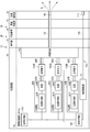

Classifications
-
- A—HUMAN NECESSITIES
- A61—MEDICAL OR VETERINARY SCIENCE; HYGIENE
- A61B—DIAGNOSIS; SURGERY; IDENTIFICATION
- A61B1/00—Instruments for performing medical examinations of the interior of cavities or tubes of the body by visual or photographical inspection, e.g. endoscopes; Illuminating arrangements therefor
- A61B1/06—Instruments for performing medical examinations of the interior of cavities or tubes of the body by visual or photographical inspection, e.g. endoscopes; Illuminating arrangements therefor with illuminating arrangements
- A61B1/07—Instruments for performing medical examinations of the interior of cavities or tubes of the body by visual or photographical inspection, e.g. endoscopes; Illuminating arrangements therefor with illuminating arrangements using light-conductive means, e.g. optical fibres
Definitions
- the present invention relates to an illuminated imaging system, an endoscope and an endoscope system.
- an endoscope system disclosed in Japanese Patent Laid-Open No. 2010-172651 includes an insertion portion of the endoscope, and an optical fiber which is disposed in the insertion portion and which guides laser light.
- the endoscope system is disposed at the tip of the optical fiber and at the tip of the insertion portion, and converts the laser light into illumination light and emits the illumination light to the outside of the tip of the insertion portion; And an exciter for vibrating the optical fiber.
- illumination light with reduced speckle noise is emitted by the vibration of the optical fiber by the excitation device, and a good observation image can be acquired.
- the present invention has been made in view of these circumstances, and it is possible to obtain an illumination imaging system capable of obtaining illumination light with uniform intensity by reducing speckle noise while maintaining quietness, an endoscope and an inside It aims at providing an endoscope system.
- one or more light source units emitting primary light and the primary light are irradiated to convert the primary light into illumination light.
- the primary light is transmitted, and one or more optical elements having a refractive index that can be changed by an external action on the primary light, and the refractive index is kept constant over time, Or one or more optical control parts which control the said optical element so that the said refractive index may change are comprised.
- an endoscope includes an insertion unit to be inserted, an operation unit disposed at a proximal end of the insertion unit, the insertion unit, and the operation unit. And a lighted imaging system as described above disposed.
- an endoscope system includes the endoscope described above and a light source device connected to the endoscope, wherein the illuminated imaging system Is extended from the endoscope to the light source device.
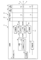
- FIG. 1 is a schematic view of an endoscope system having an illuminated imaging system according to a first embodiment of the present invention.
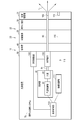
- FIG. 2 is a view schematically showing a configuration of an illumination-based imaging system in the endoscope system shown in FIG.
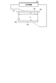
- FIG. 3A is a schematic view of an optical element and an optical control unit.
- FIG. 3B is a front view of the electrode of the optical element as viewed from the arrow 3A shown in FIG. 3A.
- FIG. 3C is a front view of an electrode having a hole.
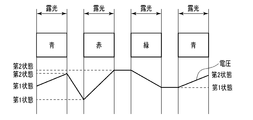
- FIG. 4 is a diagram showing the relationship between the exposure period for each wavelength and the change in voltage.
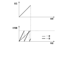
- FIG. 5 is a view showing the relationship of the phase difference for each wavelength when a voltage is applied such that the phase difference of red primary light having the longest wavelength is maximized.
- FIG. 6 is a view schematically showing the configuration of the illuminated imaging system in the endoscope system in a state in which two optical elements are arranged in series.
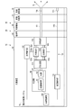
- FIG. 7A is a schematic view of an endoscope system comprising an endoscope having an illuminated imaging system according to a second embodiment.
- FIG. 7B is a view schematically showing a configuration of the illuminated imaging system in the endoscope shown in FIG. 7A.
- FIG. 8 is a view schematically showing a configuration of an illumination-based imaging system according to a third embodiment in an endoscope system.
- FIG. 9A shows a fourth embodiment and is a diagram showing an example of the relationship between the exposure period for each wavelength and the change in voltage.
- FIG. 9A shows a fourth embodiment and is a diagram showing an example of the relationship between the exposure period for each wavelength and the change in voltage.
- FIG. 9B shows the fourth embodiment and is a diagram showing an example of the relationship between the exposure period for each wavelength and the change in voltage.
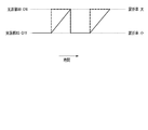
- FIG. 10 is a diagram showing the relationship between the drive of the light source unit and the refractive index in the fifth embodiment.
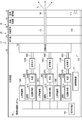
- FIG. 11 is a view schematically showing a configuration of an imaging system with illumination according to a sixth embodiment in an endoscope system.
- FIG. 12A is a view schematically showing a configuration of an illumination-based imaging system according to a seventh embodiment in an endoscope system.
- FIG. 12B is a schematic view of an optical element and an optical control unit.
- FIG. 13A is a view schematically showing the configuration of an imaging system with illumination according to the eighth embodiment in an endoscope system.
- FIG. 13B is a diagram showing the relationship between the voltage applied to each of the optical elements and the phase difference for each wavelength.
- FIG. 14A is a view schematically showing a configuration of an illumination-based imaging system according to a ninth embodiment in an endoscope system.
- FIG. 14B is a diagram showing the relationship between the voltage applied to each of the optical elements and the phase difference for each wavelength.
- the endoscope system 10 includes an endoscope 20, a light source device 50 detachably connected to the endoscope 20, and a display device 60 connected to the light source device 50 and having a monitor, for example. And.
- the endoscope 20 functions, for example, as an insertion device to be inserted into the duct.
- the endoscope 20 may be a direct-viewing endoscope or a side-viewing endoscope.
- the endoscope 20 of the present embodiment is described as, for example, a medical endoscope, it is not necessary to be limited to this.
- the endoscope 20 may be an industrial endoscope that is inserted into a pipeline of an industrial product such as a pipe.
- the endoscope 20 is mentioned as an example of a small-sized precision instrument, and in addition to the endoscope 20, an example of the precision instrument is, for example, a microscope.
- the endoscope 20 has, for example, a hollow elongated insertion portion 30 which is inserted into a body cavity, and an operation portion 40 which is connected to a proximal end portion of the insertion portion 30 and operates the endoscope 20.
- the insertion portion 30 has a distal end hard portion 31, a bendable portion 33, and a flexible tube portion 35 in order from the distal end portion side of the insertion portion 30 toward the proximal end side of the insertion portion 30.
- the proximal end of the distal end rigid portion 31 is connected to the distal end of the bendable portion 33, and the proximal end of the bendable portion 33 is connected to the distal end of the flexible tube portion 35.
- the flexible tube 35 extends from the operation unit 40.
- the operation unit 40 includes a bending operation unit 41 for bending the bendable unit 33, a switch unit 43 for air supply, water supply, suction and photographing, and a universal cord 45 extended from the side of the operation unit 40.
- a bending operation unit 41 for bending the bendable unit 33
- a switch unit 43 for air supply, water supply, suction and photographing
- a universal cord 45 extended from the side of the operation unit 40.
- the connector 45 a of the universal cord 45 is attachable to and detachable from the light source device 50.
- the endoscope system 10 includes an illuminated imaging system 70 that illuminates the illumination light IL on the object and images the object.
- the target is, for example, an affected part or a lesioned part in a body cavity.
- the imaged object is displayed on the display device 60 as an image.
- the illuminated imaging system 70 is disposed across the endoscope 20 and the light source device 50. In other words, the illuminated imaging system 70 extends from the endoscope 20 to the light source device 50.
- the imaging system with illumination 70 is disposed at a light source unit 80 for emitting primary light, light guiding members 91 and 93 for guiding primary light emitted from the light source unit 80, and an emitting end of the light guiding member 93. And the light conversion member 100.
- the light source unit 80 is disposed in the light source device 50.
- the light source unit 80 includes a light source control unit 81 and a light source 83 whose drive is controlled by the light source control unit 81.
- the light source 83 has a laser diode that emits primary light such as white laser light.
- the light source 83 can use various light sources such as LEDs or lamps.
- the light source unit 80 emits a plurality of primary lights having different wavelengths.
- the light source unit 80 has, for example, a rotary type color filter (not shown) of RGB.
- the light source 83 emits, for example, primary light of white, and the primary light having passed through the color filter is light of three primary colors of red, blue and green.
- the color filter may not be disposed, and the light source 83 may have a laser diode that emits primary light of each of red, blue and green.
- the primary light of each color may be optically coupled and travel to the light guide member 91.
- the light guide member 91 is disposed inside the light source device 50, and the light guide member 93 is disposed inside the universal cord 45, the operation unit 40 and the insertion unit 30.
- the emission end of the light guide member 93 is disposed inside the distal end hard portion 31 which is the inside of the distal end of the insertion portion 30.
- the light guide members 91 and 93 include, for example, optical fibers.
- the optical fiber may be a single-wire optical fiber or a bundle fiber.
- the light conversion member 100 is disposed inside the distal end portion of the insertion portion 30.
- the light conversion member 100 is guided by the light guide members 91 and 93 and is irradiated with primary light emitted from the emission end of the light guide member 93.
- the light conversion member 100 converts at least a portion of the primary light into illumination light IL which is secondary light having an optical characteristic different from that of the primary light, and emits the illumination light IL.
- Such a light conversion member 100 has, for example, a diffusion member.
- the diffusion member has the same wavelength as the wavelength of the primary light without changing the wavelength of the primary light, and at least a part of the primary light irradiating the diffusion member is different from the distribution angle of the primary light Convert to secondary light having a light distribution angle. Then, the diffusion member emits the secondary light as white illumination light IL toward the object.
- the diffusion referred to herein includes, for example, refraction, diffraction, and scattering, and the traveling direction of the diffused light changes to 2 or more by diffusion. Therefore, the illumination range of the illumination light IL emitted to the outside is expanded.
- the term "outside" refers to the front side, the opposite side to the light guide members 91 and 93, and the right side in FIG.
- the diffusion member has a plurality of diffusion particles (not shown) and an inclusion member (not shown) containing the diffusion particles.
- the diffusing particles are dispersed inside the containing member and sealed by the containing member.
- the diffusion particles are, for example, fine particles formed of a metal or a metal compound. Such diffusion particles are, for example, alumina, titanium oxide, barium sulfate and the like.
- the particle size of the diffusion particles is, for example, several hundred nm to several tens of ⁇ m.
- the refractive index of the diffusing particles is different from the refractive index of the inclusion member.
- the refractive index of the diffusing particles is preferably higher than the refractive index of the inclusion member. As a result, the diffusing particles can improve the diffusivity of light.
- the inclusion member is formed of a member through which primary light and secondary light are transmitted.
- Such an inclusion member is, for example, a transparent silicone resin or a transparent epoxy resin.
- the inclusion member has high transmittance to primary light and secondary light.
- the containing member seals the containing member.
- the inclusion member may be glass that seals diffusion particles that is alumina.
- the light conversion member may change the primary light into illumination light IL having a desired light distribution or the like. Therefore, the light conversion member 100 is not limited to the diffusion member, and may have another member such as a fluorescence member that emits fluorescence as the illumination light IL.
- the illuminated imaging system 70 includes an imaging device 110 that captures an image of an object illuminated with the illumination light IL.
- the image may include at least one of a still image and a moving image.
- the imaging device 110 exposes the imaging control unit 111 to capture an image, and the exposure is controlled by the imaging control unit 111.
- the imaging control unit 111 and the imaging unit 113 are electrically connected to each other. And an imaging cable 115 connected to each other.
- the imaging unit 113 is disposed inside the distal end of the insertion unit 30.
- the imaging unit 113 is adjacent to the light conversion member 100.
- the imaging unit 113 has, for example, a CCD or a CMOS.
- the imaging unit 113 may adopt a surface sequential method of receiving red, green and blue in this order.
- the imaging control unit 111 is disposed in the light source device 50, and most of the imaging cable 115 is disposed inside the endoscope 20.
- the imaging cable 115 transmits the image captured by the imaging unit 113 to the imaging control unit 111 as an electrical signal.
- the imaging control unit 111 functions as an image processing unit that processes an image transmitted by the imaging cable 115.
- the image processed by the imaging control unit 111 is displayed by the display device 60.
- the illuminated imaging system 70 includes an optical control unit 120 and an optical element 130.
- the optical element 130 is a transparent member capable of transmitting primary light.
- the optical element 130 has a refractive index for primary light.
- the optical element 130 may change the refractive index of the optical element 130 as desired with respect to the primary light transmitted through the optical element 130.
- the refractive index may be changeable by an external action from the optical control unit 120, and may be adjusted as desired.
- the external action may be, for example, a change in voltage applied to the optical element 130 by the optical control unit 120.
- the external action does not have to be limited to this, and may be, for example, a change in ultrasonic waves generated from a transducer (not shown) in accordance with the electrical signal applied from the optical control unit 120.
- the transducer is provided to the optical element 130.
- the voltage and the electric signal described above are controlled by the optical control unit 120 to adjust the refractive index.
- the optical element 130 is appropriately selected to have the ability to change the refractive index by the voltage or the ultrasonic wave applied from the optical control unit
- Examples of such an optical element 130 include, for example, at least one of an electro-optical element whose refractive index changes with an applied voltage, and an acousto-optical element whose refractive index changes with an applied ultrasonic wave.
- the electro-optical elements include, for example, KDP (potassium dihydrogen phosphate), KTN (potassium tantalate niobate), LiTaO 3 , LiNbO 3 , KD 2 PO 4 , Ba 2 NaNb 5 O 15 , Sr It has one of 0.25 Ba 0.75 Nb 2 O 6 , BaTiO 3 , CuCl, ZnTe, and liquid crystal.
- the acousto-optic element includes, for example, PbM 0 O 4 , TeO 2, Pb 5 (GeO 4 ) (VO 4 ) 2 , ⁇ -HgS, Ge, NiNbO 3 , fused silica, Te glass, AS 2 S 3 , AS 2 Se 3 Have either.
- the optical element 130 will be described as an electro-optical element configured of potassium dihydrogen phosphate.
- the optical element 130 is disposed on the traveling path of the primary light traveling from the light source unit 80 to the light conversion member 100 via the light guiding members 91 and 93. On this traveling path, the optical element 130 is disposed, for example, in the light source device 50.
- the optical element 130 may be disposed on the hand side such as the operation unit 40, for example.
- the optical element 130 is preferably disposed at a site other than the insertion portion 30.
- One reason for this is, for example, that the insertion portion 30 can be relatively easily thinned by the optical element 130 being not disposed in the insertion portion 30.
- the optical element 130 has an incident end 131 where primary light is arranged to be incident on the optical element 130, and an output which is arranged because primary light is emitted from the optical element 130.
- An end portion 133 and an electrode 135 disposed at each of the incident end portion 131 and the output end portion 133 and to which a voltage is applied from the optical control unit 120 are provided.
- the optical element 130 is disposed between the light guide members 91 and 93 and is optically connected to the light guide members 91 and 93.
- the light guiding member 91 is disposed between the light source unit 80 and the incident end 131
- the light guiding member 93 is disposed between the light emitting end 133 and the light conversion member 100.
- the light guide member 91 guides the primary light emitted from the light source unit 80 from the light source unit 80 to the incident end portion 131.
- the light guide member 93 guides the primary light emitted from the emission end portion 133 from the emission end portion 133 to the light conversion member 100.
- the area of the incident end 131 and the electrode 135 is larger than the area of the beam spot of the primary light formed at the incident end 131, and the beam spot is accommodated in the electrode 135.
- the electrode 135 is disposed along a plane substantially orthogonal to the traveling direction of the primary light.
- the traveling direction of the primary light indicates the direction from the left side to the right side in FIGS. 2 and 3A.
- the electrode 135 is disposed along a plane substantially orthogonal to the central axis of the primary light emitted from the light source unit 80.
- the electrode 135 is, for example, indium tin oxide.
- each of the electrodes 135 is, for example, transparent.
- Each of the electrodes 135 does not have to be transparent, and may have a hole 135a through which primary light can pass as shown in FIG. 3C.
- the hole 135a is larger than the beam spot, and the beam spot fits in the hole 135a.
- optical connection between the optical element 130 and the light guide members 91 and 93 will be described.
- the exit end of the light guide member 91 may be fixed to the entrance end 131 or may be inserted into the hole 135 a in the entrance end 131.
- the incident end of the light guide member 93 may be fixed to the output end 133 or may be inserted into the hole 135 a in the output end 133.
- a first parallel member is disposed between the output end of the light guide member 91 and the incident end 131 of the optical element 130 in the traveling direction of the primary light, and the first parallel member and the input end
- a first light collecting member may be disposed between the first light source 131 and the second light source 131.
- a second parallel member is disposed between the output end portion 133 of the optical element 130 and the incident end portion of the light guide member 93, and the second parallel member and the incident end portion of the light guide member 93
- the second light collecting member may be disposed between the two.
- the first and second parallel members and the first and second light collecting members each have a lens.
- the first parallel member converts primary light emitted from the output end of the light guide member 91 into first parallel light.
- the first condensing member condenses the first parallel light, which is primary light, on the incident end 131.
- the first parallel member converts the primary light emitted from the emission end portion 133 into second parallel light.
- the second condensing member condenses the second parallel light, which is primary light, on the incident end of the light guiding member 93. If the first parallel member and the first light collecting member are disposed, the light guide member 91 may be omitted.
- the primary light may travel in the order of the light guide member 91, the optical element 130, and the light guide member 93.
- the optical control unit 120 is disposed in the light source device 50.
- the optical control unit 120 controls the optical element 130 so that the refractive index is kept constant or the refractive index changes as time passes.
- This control indicates, for example, application of a voltage to the optical element 130.
- the refractive index is kept constant and does not change.
- the rate of change in voltage indicates the slope shown in FIG. 4 and corresponds to the rate of change in refractive index (slope).
- a change in voltage causes a distribution of refractive index to occur in the optical element 130.
- the optical control unit 120 causes the change of the refractive index of the optical element 130 by the change of the voltage applied to the optical element 130.
- the rate of change in voltage and the rate of change in refractive index during the exposure period of the imaging unit 113 are continuous.
- the change in voltage indicates a continuous change from the first state where the voltage is low to a second state where the voltage is high, or a continuous change from the second state to the first state.
- the voltage gradually changes from the first state to the second state, or gradually changes from the second state to the first state.
- the rate of change in voltage and the rate of change in refractive index are the same and constant for each wavelength of the color of the image captured by the imaging unit 113 in the present embodiment.
- the first state and the second state for each wavelength are identical to each other.
- the constant voltage indicates that the first state or the second state is maintained.
- the circular constant is ⁇
- the refractive index of the optical element 130 when the voltage is 0 V is n
- the effective Pockels coefficient of the optical element 130 is r
- the wavelength of primary light is ⁇
- the phase difference is ⁇ .
- the refractive index n and the effective Pockels coefficient r are proportional constants.
- the phase difference ⁇ is calculated by the following equation (1) using the circle ratio ⁇ , the refractive index n, the effective Pockels coefficient r, the wavelength ⁇ , and the voltage V.
- the application start time of the voltage to the optical element 130 is set as the start time T1
- the application end time of the voltage is set as the end time T2. Therefore, the start time T1 is the time when the change of the refractive index starts, and the end time T2 is the time when the change of the refractive index ends.
- the refractive index of the optical element 130 changes continuously from the start time T1 to the end time T2
- the phase of the primary light emitted from the optical element 130 at the start time T1 is emitted from the optical element 130 at the end time T2. Changes by approximately ⁇ radians or approximately 2 ⁇ radians with respect to the phase of primary light.
- the primary light incident on the optical element 130 is deflected by the optical element 130 and emitted from the optical element 130 in a deflected state.
- the illuminated imaging system 70 is disposed in the light source device 50, and controls the light source controller 81 of the light source unit 80, the imaging controller 111 of the imaging device 110, and the optical controller 120 in synchronization with each other.
- the main body control unit 140 is provided.
- the body control unit 140 controls the light source control unit 81, the imaging control unit 111, and the optical control unit 120, for example, by synchronizing the timing of time.
- the main body control unit 140 controls the optical control unit 120 so that the refractive index changes in an arbitrary period from the start of the exposure of the imaging unit 113 to the end of the exposure of the imaging unit 113.
- the illumination light IL is emitted.
- the body control unit 140 changes the voltage applied to the optical element 130 while the imaging unit 113 is exposing, and the light source control unit 81 changes the refractive index due to this change.
- the imaging control unit 111 and the optical control unit 120 are controlled in synchronization with each other in time.
- the voltage changes continuously, and the refractive index also changes continuously. Thereby, the effect of reducing speckle noise in primary light can be increased.
- the main body control unit 140 also controls the light source control unit 81 and the imaging control unit so that the voltage applied to the optical element 130 becomes constant while the imaging unit 113 is not exposing, and the refractive index becomes constant with a constant voltage.
- the control unit 111 controls the optical control unit 120 in synchronization with each other in time. As a result, the frequency with which voltage changes occur is reduced, so that the electrical load on the optical element 130 can be reduced and the life of the optical element 130 can be easily extended.
- each phase difference ⁇ between red primary light and blue primary light is approximately ⁇ radian It is necessary to make the above change. Focusing on the equation (1) and the wavelength ⁇ r longer than the wavelength ⁇ b, the phase difference ⁇ of red primary light is smaller by approximately ⁇ than the phase difference ⁇ of blue primary light.
- the body control unit 140 adjusts the optical control unit 120 so that the voltage applied to the optical element 130 is optimized for the red primary light having the longest wavelength.
- the voltage applied to the optical element 130 by the optical control unit 120 for the change of the refractive index is a voltage at which the phase of the wavelength of the red primary light having the longest wavelength changes to approximately ⁇ radian or more. .
- the phase difference between each of the red primary light and the blue primary light is increased, and the effect of reducing speckle noise in the primary light can be increased.
- the same effect can be obtained for the wavelength ⁇ g of the green primary light.
- At least one of the light source control unit 81, the imaging control unit 111, the optical control unit 120, and the main body control unit 140 is configured by a hardware circuit including, for example, an ASIC. At least one of these may be configured by a processor. When at least one of these is configured by a processor, an internal memory or an external memory (not shown) accessible by the processor is arranged. The internal memory or the external memory stores program code for causing the processor to function as at least one of them when executed by the processor.
- the light source control unit 81, the imaging control unit 111, the optical control unit 120, and the main body control unit 140 may be configured using one processor or may be configured using a plurality of processors. In the latter case, it is also possible to mutually transmit and receive data and process in cooperation.
- the light source control unit 81, the imaging control unit 111, the optical control unit 120, and the main body control unit 140 are disposed in the light source device 50, it is not necessary to be limited to this. A part of the light source control unit 81, the imaging control unit 111, the optical control unit 120, and the main body control unit 140 is disposed in the housing of the light source device 50, and the remaining part is a housing different from the housing of the light source device 50.
- a processor having a part of the functions of the light source control unit 81 is disposed in a housing of the light source device 50, and another processor having a part of the remaining functions of the light source control unit 81 is a housing of the light source device 50 May be arranged in different housings.
- This content is also applicable to the imaging control unit 111, the optical control unit 120, and the main body control unit 140.
- the primary light which is laser light is coherent.
- the electric field of the light oscillates temporally in the object.
- the main body control unit 140 controls the light source control unit 81, the imaging control unit 111, and the optical control unit 120 in synchronization.
- the light source unit 80 is driven, and primary light is emitted from the light source unit 80.
- the refractive index of the optical element 130 changes continuously due to the continuous change of the voltage which is an external action from the optical control unit 120.
- the primary light is emitted from the optical element 130 a in a state where speckle noise is reduced, and is then guided to the light conversion member 100 by the light guide member 93.
- the primary light is converted into secondary light by the light conversion member 100, and the secondary light is emitted to the outside as illumination light IL. Since speckle noise is reduced in primary light, speckle noise is also reduced in the illumination light IL.
- speckle noise in primary light can be reduced by the refractive index of the optical element 130 that changes due to an external action from the optical control unit 120.
- vibration to the light guide members 91 and 93 can be made unnecessary, and silence can be ensured. Therefore, in the present embodiment, the illumination control system 120 and the imaging device 70 capable of obtaining the illumination light IL having a uniform intensity and reduced speckle noise while maintaining silence by the optical control unit 120 and the optical element 130 A mirror 20 and an endoscope system 10 can be provided.
- the main control unit 140 controls the imaging control unit 111 and the optical control unit 120 so that the voltage (refractive index) applied to the optical element 130 is constant while the imaging unit 113 is not exposing light.
- the voltage (refractive index) applied to the optical element 130 is constant while the imaging unit 113 is not exposing light.
- the frequency with which voltage changes occur is reduced, so that the electrical load on the optical element 130 can be reduced and the life of the optical element 130 can be easily extended.
- the phase of the primary light can be shifted temporally, and speckle noise in the primary light can be reduced.
- the optical element 130 and the optical control unit 120 are disposed in the light source device 50, and the vibration mechanism disposed in the insertion portion 30 and vibrating the light guide members 91 and 93 can be eliminated. Therefore, in the present embodiment, the insertion portion 30 can be made thinner.
- the vibration affects internal members disposed inside such as the imaging cable 115 disposed inside the insertion portion 30.
- the vibration since the vibration is unnecessary, it is possible to prevent the occurrence of the influence of the vibration on the internal member.
- the optical element 130 according to the present embodiment may be disposed in the insertion portion 30. Even in this case, silence can be ensured, and the occurrence of the influence of the vibration on the internal member can be prevented.
- the optical element 130 at least one of an electro-optical element and an acousto-optical element can be mentioned. Therefore, the degree of freedom in design of the optical element 130 can be improved.
- only one optical element 130 is disposed, but it is not necessary to be limited to this.
- a plurality of optical elements 130a and 130c such as two may be arranged in series.
- the configuration of each of the optical elements 130 a and 130 c is the same as the configuration of the optical element 130.
- the optical elements 130 a and 130 c are optically connected to each other by, for example, a light guide member 91 a which is an optical fiber similar to the light guide member 93.
- the primary light emitted from the optical element 130a is guided to the optical element 130c by the light guide member 91a.
- One optical control unit 120 may independently control the voltage applied to each of the optical elements 130 a and 130 c. Thereby, the refractive index of each of the optical elements 130a and 130c can be changed independently. Alternatively, the optical control unit 120 may control the optical elements 130a and 130c so that the same voltage is applied to the optical elements 130a and 130c.
- the endoscope 20 is directly connected to a light source device 50 which is a peripheral device of the endoscope 20 via a universal cord 45 including a connector 45a.
- the universal cord 45 is omitted, and the endoscope 20 is of the wireless type.
- the endoscope 20 is a wireless type in which a wireless signal is transmitted and received between the operation unit 40 and the control device 200 of the endoscope system 10.
- the endoscope 20 is connected to the control device 200 which is a peripheral device of the endoscope 20 by a wireless signal.
- the illuminated imaging system 70 of the present embodiment is an example of an illuminated imaging system for an endoscope mounted on the endoscope 20 of the endoscope system 10, for example.
- the imaging system with illumination 70 is disposed in the insertion unit 30 and the operation unit 40.
- the light guide member 93 is disposed inside the insertion unit 30, and the light source unit 80, the light guide member 91, the imaging control unit 111, the optical control unit 120, the optical element 130, and the main body control unit 140 are operating units 40.
- Placed inside the The light source unit 80, the imaging control unit 111, the optical control unit 120, and the main body control unit 140 are supplied with energy from a supply unit 210 disposed inside the operation unit 40.
- the supply unit 210 includes a battery that supplies energy, for example, power.
- the supply unit 210 also supplies energy to each member of the endoscope 20.
- the imaging control unit 111 generates a video signal based on an electrical signal as an image of an object captured by the imaging unit 113, converts the video signal into a wireless signal, and transmits the wireless signal to the control device 200.
- the control device 200 converts the wireless signal into a video signal, and further performs image processing on the video signal. Then, the display device 60 displays the video signal as an image.
- the endoscope 20 having the illuminated imaging system 70 can be provided.
- the configuration shown in FIG. 6 in which a plurality of optical elements 130 are disposed can be incorporated.
- the optical control unit 120 is electrically connected to the main body control unit 140 and is directly controlled by the main body control unit 140.
- the control method of the optical control unit 120 is not limited to this, and in the present embodiment, an example thereof will be described below.
- the optical control unit 120 is electrically connected to the light source control unit 81 and synchronized with the light source control unit 81. Specifically, while the light source control unit 81 controls the light source 83, the optical control unit is controlled so that the voltage (refractive index) changes continuously while the light source 83 is driven and primary light is emitted. Reference numeral 120 synchronizes with the light source control unit 81 to control the optical element 130. Further, while the light source control unit 81 is not controlling the light source 83, in detail, the optical control unit 120 is configured so that the voltage (refractive index) becomes constant while the light source 83 is stopped and primary light is not emitted. Controls the optical element 130 in synchronization with the light source control unit 81.
- the specifications of the main body control unit 140 can be simplified, and the cost of the imaging system with illumination 70 can be suppressed.
- the configuration of this embodiment may be incorporated into the second embodiment.
- phase difference of the primary light per exposure period of the imaging unit 113 is changed to about ⁇ radian or more, preferably about 2 ⁇ radian or more, in order to enhance the effect of removing the speckle noise in the primary light. preferable.
- the phase difference ⁇ is proportional to the voltage V, but as is apparent from the equation (1), the proportional constant varies depending on the wavelength.
- the change in the voltage applied to the optical element 130 by the optical control unit 120 is changed by the imaging unit 113 so that the change amount of the refractive index becomes substantially equal at all wavelengths.
- the optical control unit 120 sets the voltage so as to be different for each wavelength of the color of the image to be captured. That is, the rate (tilt) of change in voltage in the exposure period differs for each wavelength of the color of the image captured by the imaging unit 113.
- the first states for each wavelength are identical to each other, and the second states for each wavelength are different from each other.
- the first states for each wavelength may be the same as or different from each other.
- a period in which the exposure is not performed is referred to as a non-exposure period.
- the non-exposure period indicates a period from an end time T3 when an exposure period of a certain color ends to a start time T4 when an exposure period of another color starts.
- the rate (slope) of change in voltage during this non-exposure period may be gradual.
- the voltage does not immediately change from the second state to the first state.
- the voltage gradually and continuously changes from the second state of a certain color to the first state of another color. From the end time T3 to the start time T4, the voltage may remain in the first state or the second state.
- the optical control unit 120 applies a voltage to the optical element 130 so that the rate of change of the voltage in the non-exposure period is gradual.
- the first state and the second state at each of the end time T3 and the start time T4 may be different from each other.
- the electrical load on the optical element 130 can be reduced, and the life of the optical element 130 can be easily extended.
- the effect of reducing speckle noise for each wavelength can be obtained equally for each wavelength, and color reproducibility can be enhanced.
- the present embodiment may be incorporated into each of the embodiments described above.
- the light source unit 80 pulse-oscillates the primary light.
- the main body control unit 140 controls the oscillation timing via the light source control unit 81.
- the optical control unit 120 controls the optical element 130 in synchronization with pulse oscillation.
- ON and OFF of driving of the light source unit 80 are indicated by a broken line, and changes in refractive index are indicated by a solid line.
- the main body control unit 140 controls the optical control unit 120 so that the refractive index changes between the start of oscillation of one pulse and the end of oscillation. This control indicates application of a voltage to the optical element 130.
- the refractive index is continuously increased, and when the light source unit is turned off, the refractive index is decreased.
- speckle noise in pulse-oscillated primary light can be efficiently reduced.
- the present embodiment may be incorporated into each of the embodiments described above.
- the primary light is split into two between the light source unit 80 and the light conversion member 100 and then optically coupled into one.
- the number of branched waves is not limited to two, and may be plural.
- the optical element 130 and the optical control unit 120 are arranged according to the number. Therefore, the plurality of optical elements 130 and the plurality of optical control units 120 may be disposed.
- optical control units 120 and the two optical elements 130 will be referred to as optical control units 120 a and 120 c and optical elements 130 a and 130 c for convenience of description.
- Each of the optical control units 120a and 120c independently controls each of the optical elements 130a and 130c.
- the optical elements 130a and 130c are arranged in parallel.
- the optical control units 120 a and 120 c and the optical elements 130 a and 130 c are disposed in the light source device 50.
- the imaging system with illumination 70 splits the primary light into the optical elements 130a and 130c, and the light coupling portion 153 that optically couples the primary light transmitted through the optical elements 130a and 130c.
- the light demultiplexing unit 151 and the light coupling unit 153 are disposed, for example, in the light source device 50.
- the optical elements 130 a and 130 c and the light demultiplexing unit 151 may be disposed in the light source device 50, and the light coupling unit 153 may be disposed in the endoscope 20.
- the optical elements 130 a and 130 c, the light demultiplexing unit 151, and the light coupling unit 153 may be disposed in the endoscope 20.
- the light demultiplexing unit 151 is optically connected to the light source unit 80 by the light guide member 91.
- the light demultiplexing unit 151 is optically connected to the incident end of the optical element 130a by the light guide member 95a, and is optically connected to the incident end of the optical element 130c by the light guide member 95b.
- the light coupling portion 153 is optically connected to the output end of the optical element 130a by the light guide member 95c, and is optically connected to the output end of the optical element 130c by the light guide member 95d.
- the light coupling portion 153 is optically connected to the light conversion member 100 by the light guide member 93.
- the primary light is emitted from the light source unit 80, is guided to the light branching unit 151 by the light guiding member 91, and is branched into the light guiding members 95a and 95b by the light branching unit 151.
- the ratio of the amount of primary light traveling to each of the light guide members 95a and 95b is preferably 1: 1, but may be adjusted as desired.
- a portion of the primary light is guided by the light guide member 95a to the optical element 130a, and this primary light is transmitted through the optical element 130a.
- the refractive index of the optical element 130a continuously changes due to the continuous change of the voltage which is an external action from the optical control unit 120a.
- primary light is emitted from the optical element 130 a in a state in which speckle noise is reduced, and is then guided to the light coupling portion 153 by the light guide member 95 c.
- the primary light is guided to the optical element 130c by the light guide member 95b, and this primary light passes through the optical element 130c.
- the refractive index of the optical element 130c continuously changes due to the continuous change of the voltage which is an external action from the optical control unit 120c.
- the primary light is emitted from the optical element 130c in a state in which speckle noise is reduced, and is then guided to the light coupling portion 153 by the light guide member 95d.
- the two primary lights are optically coupled by the light coupling portion 153 and guided to the light conversion member 100 by the light guiding member 93. Then, the primary light is converted into secondary light by the light conversion member 100, and the secondary light is emitted to the outside as illumination light IL. Since speckle noise is reduced in primary light, speckle noise is also reduced in the illumination light IL.
- optical control units 120a and 120c are disposed in the optical elements 130a and 130c, respectively. Therefore, different voltages can be applied to the optical elements 130a and 130c, and the refractive indices of the optical elements 130a and 130c can be changed independently. Thereby, speckle noise in the illumination light IL can be reliably reduced.
- the configuration of the present embodiment may be incorporated into the above-described second to fifth embodiments.
- one optical control unit 120 controls each of the optical elements 130 a and 130 c.
- the proportionality constant may be changed in the formula (1) of each of the optical elements 130a and 130c so that a phase difference occurs in the primary light emitted from each of the optical elements 130a and 130c.
- the proportional constant indicates at least one of the refractive index n and the effective Pockels coefficient r.
- the electrode 135 may be disposed along a plane substantially parallel to the traveling direction of the primary light.
- the electrode 135 may be disposed along a plane substantially parallel to the central axis of the primary light emitted from the light source unit 80.
- the length of the optical element 130a along substantially parallel to the central axis of the primary light is L
- the optical element 130a substantially orthogonal to the central axis of the primary light Let d be the diameter of The diameter d is a length excluding the thickness of the electrode 135.
- the phase difference ⁇ is calculated by the following equation (2) using the equation (1), the length L, and the diameter d.
- each of the optical elements 130a and 130c Even if the material of each of the optical elements 130a and 130c is not changed, the arrangement of each of the optical elements 130a and 130c and the size of each of the optical elements 130a and 130c (at least one of the length L and the diameter d) are changed. Even if the same voltage is applied to each of the optical elements 130a and 130c, it is possible to shift the phase of the primary light both temporally and spatially. This also makes it possible to reduce speckle noise in primary light more easily and reliably.
- only one optical control unit 120 may be prepared, and the illumination imaging system 70 can be miniaturized, and the cost of the illumination imaging system 70 can be suppressed.
- the configuration of the present embodiment may be incorporated into the above-described second to fifth embodiments.
- the light source unit 80 (the light source control unit 81 and the light source 83), the light guide members 97 and 99, the optical element 130, and the optical control unit 120 are disposed for each wavelength.
- the light source unit 80 (light source control unit 81 and light source 83), the light guide members 97 and 99, the optical element 130, and the optical control unit 120 arranged for each wavelength 80R, 80G, 80B (light source control units 81R, 81G, 81B and light sources 83R, 83G, 83B), light guiding members 97R, 97G, 97B, 99R, 99G, 99B and optical elements 130R, 130G, 130B and optical control
- the units are referred to as 120R, 120G, and 120B.
- the light source 83R has, for example, a laser diode that emits red laser light.
- the central wavelength of the laser light is, for example, 635 nm.
- the light source 83G includes, for example, a laser diode that emits green laser light.
- the central wavelength of the laser light is, for example, 532 nm.
- the light source 83B includes, for example, a laser diode that emits blue laser light.
- the central wavelength of the laser light is, for example, 445 nm.
- the plurality of light source units 80R, 80G, and 80B respectively emit a plurality of primary lights having different wavelengths.
- the light guide member 97R is optically connected to the light source 83R and the optical element 130R, and guides the red primary light emitted from the light source 83R to the optical element 130R.
- the light guide member 99R is optically connected to the optical element 130R and the light coupling portion 153, and guides the red primary light emitted from the optical element 130R to the light coupling portion 153.
- the light guide member 97G is optically connected to the light source 83G and the optical element 130G, and guides the green primary light emitted from the light source 83G to the optical element 130G.
- the light guiding member 99G is optically connected to the optical element 130G and the light coupling portion 153, and guides the green primary light emitted from the optical element 130G to the light coupling portion 153.
- the light guide member 97B is optically connected to the light source 83B and the optical element 130B, and guides the blue primary light emitted from the light source 83B to the optical element 130B.
- the light guide member 99B is optically connected to the optical element 130B and the light coupling portion 153, and guides the blue primary light emitted from the optical element 130B to the light coupling portion 153.
- the plurality of optical elements 130R, 130G, and 130B are disposed for each of the light source units 80R, 80G, and 80B.
- the light coupling unit 153 optically couples the plurality of primary lights having different wavelengths guided by the light guiding members 99R, 99G, and 99B. If the wavelengths of the primary light are different from one another and the laser light has blue, green and red wavelengths as described above, the light coupled light is, for example, white light.
- the light coupling portion 153 is optically connected to the light guide member 93, and emits the optically coupled white light toward the light guide member 93 as primary light. Then, the primary light is guided by the light guide member 93 and travels to the light conversion member 100. Thereby, white light observation can be performed.
- a plurality of primary lights having different wavelengths are used, and independent optical elements 130R, 130G, and 130B and optical control units 120R, 120G, and 120B are disposed for each wavelength. Therefore, different voltages are applied to the optical elements 130R, 130G, and 130B, respectively.
- an optimum voltage for each wavelength is applied to each of the optical elements 130R, 130G, and 130B such that the phase difference is maximized for each wavelength.
- voltages applied to the optical elements 130R, 130G, and 130B are voltages V1, V2, and V3, respectively.
- the voltage V1 is larger than the voltage V2
- the voltage V2 is larger than the voltage V3.
- the phase difference becomes maximum for each wavelength.
- the optimum phase difference can be controlled for each wavelength, speckle noise for each wavelength can be reduced, and color reproducibility can be enhanced.
- the imaging device 110 simultaneously images each wavelength, this embodiment is preferable.
- the optical element 130 may be disposed for each wavelength of the color of the image captured by the imaging unit 113. This embodiment may be incorporated into the above-described second to seventh embodiments.
- the ninth embodiment The ninth embodiment of the present invention will be described below with reference to FIGS. 14A and 14B. In the present embodiment, only differences from the eighth embodiment will be described.
- only one optical control unit 120 is disposed, and is shared by the optical elements 130B, 130G, and 130R.
- the materials of the optical elements 130B, 130G, and 130R are mutually changed to form the optical element 130B.
- the refractive index n and the effective Pockels coefficient r may be changed.
- the electrodes 135 of the optical elements 130B, 130G, and 130R are disposed along a plane substantially parallel to the central axis of the primary light emitted from the light source unit 80. It may be done. Thereby, Formula (2) can be utilized. Therefore, even if the same voltage is applied to each of the optical elements 130B, 130G, and 130R by changing the arrangement of the optical elements 130B, 130G, and 130R, and the dimensions of each of the optical elements 130B, 130G, and 130R, the optimal position for each wavelength It becomes a difference.
- the optimum phase difference can be controlled for each wavelength, speckle noise for each wavelength can be reduced, and color reproducibility can be enhanced.
- only one optical control unit 120 may be prepared, and the illumination imaging system 70 can be miniaturized, and the cost of the illumination imaging system 70 can be suppressed. This embodiment may be incorporated into the above-described second to seventh embodiments.
- the present invention is not limited to the above embodiment, and can be variously modified in the implementation stage without departing from the scope of the invention.
- the embodiments may be implemented in combination as appropriate as possible, in which case the combined effect is obtained.
- the above embodiments include inventions of various stages, and various inventions can be extracted by an appropriate combination of a plurality of disclosed configuration requirements.
Landscapes
- Health & Medical Sciences (AREA)
- Life Sciences & Earth Sciences (AREA)
- Surgery (AREA)
- Biomedical Technology (AREA)
- Medical Informatics (AREA)
- Optics & Photonics (AREA)
- Pathology (AREA)
- Radiology & Medical Imaging (AREA)
- Biophysics (AREA)
- Engineering & Computer Science (AREA)
- Physics & Mathematics (AREA)
- Heart & Thoracic Surgery (AREA)
- Nuclear Medicine, Radiotherapy & Molecular Imaging (AREA)
- Molecular Biology (AREA)
- Animal Behavior & Ethology (AREA)
- General Health & Medical Sciences (AREA)
- Public Health (AREA)
- Veterinary Medicine (AREA)
- Instruments For Viewing The Inside Of Hollow Bodies (AREA)
- Endoscopes (AREA)
Abstract
照明付き撮像システム(30)は、1次光を出射する光源部(80)と、1次光を照明光に変換して出射する光変換部材(100)と、照明光を照明された対象物の画像を撮像する撮像装置(110)とを有する。照明付き撮像システム(30)は、光源部(80)から光変換部材(100)に進行する1次光の進行経路上に配置され、1次光が透過し、1次光に対して外的作用によって変化可能な屈折率を有する1以上の光学素子(130)と、時間の経過とともに、屈折率が一定に保たれるように、または屈折率が変化するように、光学素子(130)を制御する光学制御部(120)とを有する。
Description
本発明は、照明付き撮像システム、内視鏡及び内視鏡システムに関する。
例えば、日本国特開2010-172651号公報に開示される内視鏡システムは、内視鏡の挿入部と、挿入部に配置され、レーザ光を導光する光ファイバとを有する。内視鏡システムは、光ファイバの先端及び挿入部の先端に配置され、レーザ光を照明光に変換して照明光を挿入部の先端の外部に出射する蛍光体と、挿入部の先端側にて光ファイバを振動する加振装置とを有する。この内視鏡システムでは、加振装置による光ファイバの振動によってスペックルノイズが低減された照明光が出射され、良好な観察画像を取得できる。
日本国特開2010-172651号公報に開示される内視鏡システムでは、加振装置の振動によって、静粛性が保たれない。所望する静粛性を確保するためには、振動を抑制する必要があるが、スペックルノイズが低減されなくなり、照明光の強度は均一とならなくなる。このように、静粛性を保ちつつ、スペックルノイズが低減されて強度が均一な照明光を得ることは困難である。
本発明は、これらの事情に鑑みてなされたものであり、静粛性を保ちつつ、スペックルノイズが低減されて強度が均一な照明光を得ることができる照明付き撮像システム、内視鏡及び内視鏡システムを提供することを目的とする。
前記目的を達成するために、本発明の一態様の照明付き撮像システムは、1次光を出射する1以上の光源部と、前記1次光を照射され、前記1次光を照明光に変換して出射する光変換部材と、前記照明光を照明された対象物の画像を撮像する撮像装置と、前記光源部から前記光変換部材に進行する前記1次光の進行経路上に配置され、前記1次光が透過し、前記1次光に対して外的作用によって変化可能な屈折率を有する1以上の光学素子と、時間の経過とともに、前記屈折率が一定に保たれるように、または前記屈折率が変化するように、前記光学素子を制御する1以上の光学制御部と、を具備する。
前記目的を達成するために、本発明の一態様の内視鏡は、挿入される挿入部と、前記挿入部の基端部に配置される操作部と、前記挿入部と前記操作部とに配置される上記に記載の照明付き撮像システムと、を具備する。
前記目的を達成するために、本発明の一態様の内視鏡システムは、上記に記載の内視鏡と、前記内視鏡に接続される光源装置と、を具備し、前記照明付き撮像システムは、前記内視鏡から前記光源装置に延設される。
以下、図面を参照して本発明の各実施形態について説明する。なお、一部の図面では図示の明瞭化のために部材の一部の図示を省略する。
[第1の実施形態]
以下に、本発明の第1の実施形態について説明する。
以下に、本発明の第1の実施形態について説明する。
図1に示すように、内視鏡システム10は、内視鏡20と、内視鏡20に着脱自在に接続される光源装置50と、光源装置50に接続され、例えばモニタを有する表示装置60とを有する。
内視鏡20は、例えば、管路部に挿入される挿入機器として機能する。内視鏡20は、直視型の内視鏡であってもよいし、側視型の内視鏡であってもよい。本実施形態の内視鏡20は、例えば医療用の内視鏡として説明するが、これに限定される必要はない。内視鏡20は、パイプ等の工業製品の管路部に挿入される工業用の内視鏡であってもよい。
内視鏡20は小型な精密機器の一例として挙げているものであり、精密機器の一例は、内視鏡20の他に、例えば、顕微鏡などが挙げられる。
内視鏡20は、例えば体腔に挿入される中空の細長い挿入部30と、挿入部30の基端部に連結され、内視鏡20を操作する操作部40とを有する。
挿入部30は、挿入部30の先端部側から挿入部30の基端部側に向かって順に、先端硬質部31と、湾曲可能部33と、可撓管部35とを有する。先端硬質部31の基端部は湾曲可能部33の先端部に連結され、湾曲可能部33の基端部は可撓管部35の先端部に連結される。可撓管部35は、操作部40から延出される。
操作部40は、湾曲可能部33を湾曲操作する湾曲操作部41と、送気と送水と吸引と撮影とのためのスイッチ部43と、操作部40の側面から延出されるユニバーサルコード45とを有する。ユニバーサルコード45のコネクタ45aは、光源装置50に着脱可能となっている。
図2に示すように、内視鏡システム10は、対象物に照明光ILを照明し、対象物を撮像する照明付き撮像システム70を有する。この対象物とは、例えば体腔内における患部や病変部等である。撮像された対象物は、画像として表示装置60に表示される。照明付き撮像システム70は、内視鏡20と光源装置50とに渡って配置される。言い換えると、照明付き撮像システム70は、内視鏡20から光源装置50に延設される。
照明付き撮像システム70は、1次光を出射する光源部80と、光源部80から出射された1次光を導光する導光部材91,93と、導光部材93の出射端部に配置される光変換部材100とを有する。
例えば、光源部80は、光源装置50に配置される。例えば、光源部80は、光源制御部81と、光源制御部81によって駆動を制御される光源83とを有する。光源83は例えば白色のレーザ光といった1次光を出射するレーザダイオードを有する。光源83は、LEDまたはランプなど様々な光源を利用できる。光源部80は、互いに異なる波長を有する複数の1次光を出射する。このため、光源部80は、例えば、RGBの回転式の図示しないカラーフィルタを有する。この場合、光源83は例えば白色の1次光を出射し、カラーフィルタを通過した1次光は赤色と青色と緑色との三原色の光となる。なおカラーフィルタが配置されず、光源83は、赤色と青色と緑色とのそれぞれの1次光を出射するレーザダイオードを有してもよい。各色の1次光は、光結合されて導光部材91に進行すればよい。
導光部材91は光源装置50の内部に配置され、導光部材93はユニバーサルコード45と操作部40と挿入部30との内部に配置される。導光部材93の出射端部は、挿入部30の先端部の内部である先端硬質部31の内部に配置される。
導光部材91,93は、例えば、光ファイバを有する。光ファイバは、単線の光ファイバでもよいし、バンドルファイバでもよい。
光変換部材100は、挿入部30の先端部の内部に配置される。光変換部材100は、導光部材91,93によって導光され、導光部材93の出射端部から出射された1次光を照射される。光変換部材100は、1次光の少なくとも一部を、1次光の光学特性とは異なる光学特性を有する2次光である照明光ILに変換し、照明光ILを出射する。このような光変換部材100は、例えば、拡散部材を有する。
拡散部材は、拡散部材を照射する1次光の少なくとも一部を、1次光の波長を変えず、1次光の波長と同一の波長を有し、1次光の配光角度とは異なる配光角度を有する2次光に変換する。そして拡散部材は、2次光を白色の照明光ILとして対象物に向けて出射する。
ここでいう当該拡散は例えば屈折と回折と散乱等を含み、拡散された光の進行方向は拡散によって2以上に変化する。したがって、外部に出射される照明光ILの照明範囲は、広がる。外部とは、前方であり、導光部材91,93とは逆側を示し、図2において右側を示す。
例えば、拡散部材は、図示しない複数の拡散粒子と、拡散粒子を包含する図示しない包含部材とを有する。
拡散粒子は、包含部材の内部に分散され、包含部材によって封止される。拡散粒子は、例えば、金属または金属化合物によって形成される微粒子である。このような拡散粒子は、例えばアルミナ、酸化チタン、硫酸バリウム等である。拡散粒子の粒径は、例えば、数百nm~数十μmである。拡散粒子の屈折率は、包含部材の屈折率とは異なる。例えば、拡散粒子の屈折率は、包含部材の屈折率よりも高いことが好ましい。これにより、拡散粒子は、光の拡散性を向上可能となる。
包含部材は、1次光と2次光とが透過する部材によって形成される。このような包含部材は、例えば、透明なシリコーン系の樹脂または透明なエポキシ系の樹脂である。包含部材は、1次光と2次光とに対して高い透過率を有する。包含部材は、包含している部材を封止する。包含部材は、アルミナである拡散粒子を封止するガラスでもよい。
本実施形態では、光変換部材は、1次光を所望の配光等を有する照明光ILに変化できればよい。したがって拡散部材に限定されず、光変換部材100は、例えば、照明光ILとしての蛍光を出射する蛍光部材といった他の部材を有してもよい。
照明付き撮像システム70は、照明光ILを照明された対象物の画像を撮像する撮像装置110を有する。画像は、静止画と動画との少なくとも一方を含めばよい。撮像装置110は、撮像制御部111と、画像を撮像するために露光し、この露光を撮像制御部111によって制御される撮像部113と、撮像制御部111と撮像部113とを互いに対して電気的に接続する撮像ケーブル115とを有する。
撮像部113は、挿入部30の先端部の内部に配置される。撮像部113は、光変換部材100に隣り合う。撮像部113は、例えば、CCDまたはCMOSを有する。例えば、撮像部113は、赤色と緑色と青色とをこの順で受光する面順次方式を採用してもよい。
例えば、撮像制御部111は光源装置50に配置され、撮像ケーブル115の大部分は内視鏡20の内部に配置される。
撮像ケーブル115は、撮像部113によって撮像された画像を電気信号として撮像制御部111に伝送する。撮像制御部111は、撮像ケーブル115によって伝送された画像を処理する画像処理部として機能する。撮像制御部111によって処理された画像は、表示装置60によって表示される。
照明付き撮像システム70は、光学制御部120と、光学素子130とを有する。
光学素子130は、1次光が透過可能な、透明な部材である。光学素子130は、1次光に対する屈折率を有する。光学素子130は、光学素子130を透過する1次光に対して光学素子130の屈折率を所望に変化できればよい。この屈折率は、光学制御部120からの外的作用によって、変化可能にできればよく、所望に調整されればよい。外的作用とは、例えば、光学制御部120によって光学素子130に印加される電圧の変化でもよい。なお外的作用とは、これに限定される必要はなく、例えば、光学制御部120から印加される電気信号に応じて図示しないトランスデューサから発生する超音波の変化でもよい。トランスデューサは、光学素子130に備えられる。前記した電圧及び電気信号は、屈折率の調整のために光学制御部120によって制御されるものである。このように光学素子130は、光学制御部120から印加される電圧や超音波によって、屈折率を変化させる性能を有するものが適宜選択されるものとする。
このような光学素子130の一例として、例えば、印加される電圧によって屈折率が変化する電気光学素子と、印加される超音波によって屈折率が変化する音響光学素子との少なくとも1つが挙げられる。電気光学素子は、例えば、KDP(リン酸二水素カリウム)と、KTN(タンタル酸ニオブ酸カリウム)と、LiTaO3と、LiNbO3と、KD2PO4と、Ba2NaNb5O15と、Sr0.25Ba0.75Nb2O6と、BaTiO3と、CuClと、ZnTeと、液晶とのいずれかを有する。音響光学素子は、例えば、PbM0O4、TeO2、Pb5(GeO4)(VO4)2、α-HgS、Ge、NiNbO3、溶融石英、Teガラス、AS2S3、AS2Se3とのいずれかを有する。
本実施形態では、光学素子130がリン酸二水素カリウムから構成される電気光学素子として説明する。
光学素子130は、光源部80から導光部材91,93を経由して光変換部材100に進行する1次光の進行経路上に配置される。この進行経路上において、光学素子130は、例えば、光源装置50に配置される。光学素子130は、例えば操作部40といった手元側に配置されてもよい。詳細には、光学素子130は、挿入部30以外の部位に配置されることが好ましい。この理由の1つとして、例えば、光学素子130が挿入部30に配置されないことで、挿入部30を比較的容易に細くできることが挙げられる。
図3Aに示すように、光学素子130は、1次光が光学素子130に入射するために配置される入射端部131と、光学素子130から1次光が出射されるために配置される出射端部133と、入射端部131と出射端部133とのそれぞれに配置され、光学制御部120から電圧を印加される電極135とを有する。
光学素子130は、導光部材91,93の間に配置され、導光部材91,93に光学的に接続される。詳細には、光源部80と入射端部131との間には導光部材91が配置され、出射端部133と光変換部材100との間には導光部材93が配置される。導光部材91は、光源部80から出射された1次光を光源部80から入射端部131に導光する。導光部材93は、出射端部133から出射された1次光を出射端部133から光変換部材100に導光する。
入射端部131及び電極135の面積は入射端部131に形成される1次光のビームスポットの面積よりも大きく、ビームスポットは電極135に収まる。
電極135は、1次光の進行方向に対して略直交する平面に沿って配置される。1次光の進行方向は、図2と図3Aとの左側から右側に向かう方向を示す。詳細には、電極135は、光源部80から出射された1次光の中心軸に対して略直交する平面に沿って配置される。電極135は、例えば、酸化インジウムスズである。
図3Bに示すように、電極135それぞれは、例えば、透明である。なお、電極135それぞれは、透明である必要はなく、図3Cに示すように1次光が通過可能な孔135aを有してもよい。孔135aはビームスポットよりも大きく、ビームスポットは孔135aに収まる。
ここで、光学素子130と導光部材91,93との光学的な接続について説明する。
図示はしないが、導光部材91の出射端部は、入射端部131に固定されてもよいし、入射端部131における孔135aに挿入されてもよい。導光部材93の入射端部は、出射端部133に固定されてもよいし、出射端部133における孔135aに挿入されてもよい。
図示はしないが、1次光の進行方向において、導光部材91の出射端部と光学素子130の入射端部131との間に第1平行部材が配置され、第1平行部材と入射端部131との間に第1集光部材が配置されてもよい。また図示はしないが、光学素子130の出射端部133と導光部材93の入射端部との間とに第2平行部材が配置され、第2平行部材と導光部材93の入射端部との間に第2集光部材が配置されてもよい。例えば、第1,2平行部材と第1,2集光部材とはそれぞれ、レンズを有する。
第1平行部材は、導光部材91の出射端部から出射された1次光を第1平行光に変換する。第1集光部材は、1次光である第1平行光を入射端部131に集光する。第1平行部材は、出射端部133から出射された1次光を第2平行光に変換する。第2集光部材は、1次光である第2平行光を導光部材93の入射端部に集光する。第1平行部材と第1集光部材とが配置されていれば、導光部材91は省略されてもよい。
このように、1次光が導光部材91と光学素子130と導光部材93との順に進行できればよい。
光学制御部120は、光源装置50に配置される。光学制御部120は、時間の経過とともに、屈折率が一定に保たれるように、または屈折率が変化するように、光学素子130を制御する。この制御とは、例えば、光学素子130への電圧の印加を示す。電圧が一定に維持されると、屈折率は一定に保たれて変化しない。電圧が変化すると、屈折率が変化する。電圧の変化の割合は、図4に示す傾きを示し、屈折率の変化の割合(傾き)に対応する。詳細には、電圧の変化によって、屈折率の分布が光学素子130において発生する。言い換えると、光学制御部120は、光学素子130に印加する電圧の変化によって、光学素子130の屈折率の変化を引き起こさせる。これにより、1次光が入射端部131から出射端部133に進行する際に、位相差が1次光に生じる。
図4に示すように、撮像部113の露光期間における電圧の変化の割合及び屈折率の変化の割合は、連続的なものである。電圧の変化とは、電圧が低い第1状態から電圧が高い第2状態への連続的な変化、または第2状態から第1状態への連続的な変化を示す。電圧は、第1状態から第2状態に向けて徐々に変化する、または第2状態から第1状態に向けて徐々に変化する。電圧の変化の割合及び屈折率の変化の割合は、本実施形態では、撮像部113によって撮像される画像の色の波長毎に同一であり一定である。本実施形態では、波長毎の第1状態及び第2状態は、互いに同一である。また電圧が一定とは、第1状態または第2状態が維持されることを示す。
ここで、円周率をπとし、電圧が0Vのときの光学素子130の屈折率をnとし、光学素子130の有効ポッケルス係数をrとし、1次光の波長をλとし、位相差をΔφとする。屈折率nと有効ポッケルス係数rとは、比例定数である。位相差Δφは、円周率πと、屈折率nと、有効ポッケルス係数rと、波長λと、電圧Vとを用いる下記式(1)によって算出される。
Δφ=-πn3rV/λ ・・・式(1)。
ここで、光学素子130への電圧の印加開始時刻を開始時刻T1とし、電圧の印加終了時刻を終了時刻T2とする。したがって、開始時刻T1は屈折率の変化が開始する時刻であり、終了時刻T2は屈折率の変化が終了する時刻である。開始時刻T1から終了時刻T2において光学素子130の屈折率が連続的に変化する場合、開始時刻T1において光学素子130から出射された1次光の位相は、終了時刻T2において光学素子130から出射された1次光の位相に対して、略πラジアンまたは略2πラジアン変化する。光学素子130に入射した1次光は、光学素子130によって偏向され、偏向された状態で光学素子130から出射される。
図2に示すように、照明付き撮像システム70は、光源装置50に配置され、光源部80の光源制御部81と撮像装置110の撮像制御部111と光学制御部120とを互いに同期して制御する本体制御部140を有する。特に、本体制御部140は、例えば時間のタイミングを同期させて、光源制御部81と撮像制御部111と光学制御部120とを制御する。本体制御部140は、撮像部113の露光開始から撮像部113の露光終了までの任意の期間において屈折率が変化するように、光学制御部120を制御する。
具体的には、撮像が実施される際に、照明光ILが出射される。図4に示すように、本体制御部140は、撮像部113が露光している間に光学素子130に印加される電圧が変化し、この変化によって屈折率が変化するように、光源制御部81と撮像制御部111と光学制御部120とを互いに時間的に同期させて制御する。ここでは、電圧は連続的に変化し、屈折率も連続的に変化する。これにより、1次光におけるスペックルノイズの低減の効果を大きくできる。
また本体制御部140は、撮像部113が露光していない間に光学素子130に印加される電圧が一定となり、一定の電圧によって屈折率が一定となるように、光源制御部81と撮像制御部111と光学制御部120とを互いに時間的に同期させて制御する。これにより、電圧の変化が発生する頻度が減るため、光学素子130の電気的な負荷が減り、光学素子130の寿命を容易に延ばすことができる。
ここで、光変換部材100に進行する1次光において、赤色の1次光と青色の1次光とに着目する。赤色の1次光の波長λrは、青色の1次光の波長λbよりも長い。なお緑色の1次光の波長λgは、青色の1次光の波長λbよりも長く、赤色の1次光の波長λrよりも短い。本実施形態のように光学素子130が互いに異なる波長を有する複数の1次光に対して共有される場合、赤色の1次光と青色の1次光とのそれぞれの位相差Δφを略πラジアン以上に変化させることが必要となる。式(1)と、波長λbよりも長い波長λrとに着目すると、赤色の1次光の位相差Δφは、青色の1次光の位相差Δφよりも略λ小さい。このため赤色の1次光の位相差Δφが略πラジアン変化するだけの電圧が印加されれば、青色の1次光の位相差Δφが略πラジアン以上に変化することとなる。したがって、図5に示すように、光学素子130に印加される電圧が最も長い波長を有する赤色の1次光に対して最適化するように、本体制御部140は光学制御部120を調整する。詳細には、屈折率の変化のために光学制御部120によって光学素子130に印加される電圧は、最も波長の長い赤色の1次光の波長の位相が略πラジアン以上に変化する電圧である。これにより、赤色の1次光及び青色の1次光それぞれの位相差が大きくなり、1次光におけるスペックルノイズの低減の効果を大きくできる。ここでは図示していないが、緑色の1次光の波長λgに対しても、同様の効果を得ることができる。
光源制御部81と撮像制御部111と光学制御部120と本体制御部140との少なくとも1つは、例えば、ASICなどを含むハードウエア回路によって構成される。これらの少なくとも1つは、プロセッサによって構成されても良い。これらの少なくとも1つがプロセッサで構成される場合、プロセッサがアクセス可能な図示しない内部メモリまたは外部メモリが配置される。内部メモリまたは外部メモリは、プロセッサが実行することで当該プロセッサをこれら少なくとも1つとして機能させるためのプログラムコードを記憶する。光源制御部81と撮像制御部111と光学制御部120と本体制御部140とを、1つのプロセッサを用いて構成しても良いし、複数のプロセッサを用いて構成しても良い。後者の場合は、データを互いに送受信して連携して処理することも可能である。また、後者の場合は、これらは互いに異なる場所に配置されることも可能である。光源制御部81と撮像制御部111と光学制御部120と本体制御部140とは光源装置50に配置されるが、これに限定される必要はない。光源制御部81と撮像制御部111と光学制御部120と本体制御部140との一部は光源装置50の筐体に配置され、残りの一部は光源装置50の筐体とは異なる筐体に配置されてもよい。また例えば、光源制御部81の一部の機能を有するプロセッサは光源装置50の筐体に配置され、光源制御部81の残りの一部の機能を有する別のプロセッサは光源装置50の筐体とは異なる筐体に配置されてもよい。この内容は、撮像制御部111と光学制御部120と本体制御部140とについても適用可能である。
次に本実施形態の作用について説明する。
レーザ光である1次光は、コヒーレントである。1次光が電気光学素子を透過しない場合、当該光の電場は、対象物において時間的に単振動する。
一方、1次光が電気光学素子を透過する場合、電気光学素子の屈折率の変化によって、当該電場の位相ずれが生じ、その結果、当該単振動は乱れる。その結果、時間的にコヒーレントな程度(コヒーレンス)を低減させた状態となる。したがって、スペックルノイズを低下させることができる。
撮像が実施される際に、照明光ILが出射される必要がある。このために、本体制御部140は、光源制御部81と撮像制御部111と光学制御部120とを同期して制御する。これにより光源部80が駆動し、1次光が光源部80から出射される。1次光が光学素子130を透過する際、光学素子130の屈折率は、光学制御部120からの外的作用である電圧の連続的な変化によって、連続的に変化する。これにより1次光は、スペックルノイズが低減された状態で光学素子130aから出射された後、導光部材93によって光変換部材100に導光される。そして、1次光は光変換部材100によって2次光に変換され、2次光は照明光ILとして外部に出射される。1次光において、スペックルノイズが低減されているため、照明光ILにおいてもスペックルノイズが低減されることとなる。
本実施形態では、光学制御部120からの外的作用によって変化する光学素子130の屈折率によって、1次光におけるスペックルノイズを低減できる。本実施形態では、スペックルノイズを低減するために導光部材91,93への振動を不要にでき、静粛性を確保できる。したがって本実施形態では、光学制御部120と光学素子130とによって、静粛性を保ちつつ、スペックルノイズが低減されて強度が均一な照明光ILを得ることができる照明付き撮像システム70と内視鏡20と内視鏡システム10とを提供できる。
本実施形態では、本体制御部140は、撮像部113が露光していない間に光学素子130に印加される電圧(屈折率)が一定となるように、撮像制御部111と光学制御部120とを時間的に同期させて制御する。これにより、電圧の変化が発生する頻度が減るため、光学素子130の電気的な負荷が減り、光学素子130の寿命を容易に延ばすことができる。
本実施形態では、時間的に1次光の位相をずらすことができ、1次光におけるスペックルノイズを低減できる。
光学素子130及び光学制御部120が光源装置50に配置されており、挿入部30に配置され且つ導光部材91,93を振動する振動機構を不要にできる。したがって本実施形態では、挿入部30を細くできる。
導光部材91,93が振動すると、この振動は、挿入部30の内部に配置される撮像ケーブル115といった内部に配置される内部部材に影響を与えることが考えられる。本実施形態では、振動が不要であるため、振動による内部部材への影響の発生を防止できる。
本実施形態の光学素子130は挿入部30に配置されてもよく、この場合であっても、静粛性を確保でき、振動による内部部材への影響の発生を防止できる。
本実施形態では、光学素子130として、電気光学素子と音響光学素子との少なくとも1つが挙げられる。したがって、光学素子130における設計の自由度を向上できる。
なお本実施形態では、1つの光学素子130のみが配置されているがこれに限定される必要はない。図6に示すように、例えば、2つといった複数の光学素子130a,130cが直列に配置されてもよい。光学素子130a,130cそれぞれの構成は、光学素子130の構成と同一である。光学素子130a,130c同士は、例えば、導光部材93と同様の光ファイバである導光部材91aによって光学的に接続される。光学素子130aから出射された1次光は、導光部材91aによって光学素子130cに導光される。
1つの光学制御部120は、光学素子130a,130cそれぞれに印加される電圧を、独立して制御してもよい。これにより、光学素子130a,130cそれぞれの屈折率を独立して変化できる。または光学制御部120は、光学素子130a,130cそれぞれに同じ電圧が印加されるように、光学素子130a,130cを制御してもよい。
[第2の実施形態]
以下に、図7Aと図7Bとを参照して、本発明の第2の実施形態について説明する。本実施形態では、第1の実施形態とは異なることのみを記載する。
以下に、図7Aと図7Bとを参照して、本発明の第2の実施形態について説明する。本実施形態では、第1の実施形態とは異なることのみを記載する。
第1の実施形態の内視鏡システム10において、内視鏡20は、コネクタ45aを含むユニバーサルコード45を介して、内視鏡20の周辺装置である光源装置50に直接接続される。
しかしながら本実施形態では、図7Aに示すように、ユニバーサルコード45が省略されており、内視鏡20は、ワイヤレスタイプとなっている。この場合、内視鏡20は、無線信号が操作部40と内視鏡システム10の制御装置200との間で送受信される無線タイプとなっている。このように、内視鏡20は、無線信号によって、内視鏡20の周辺装置である制御装置200に接続される。
図7Bに示すように、本実施形態の照明付き撮像システム70は、例えば、内視鏡システム10の内視鏡20に搭載される内視鏡用の照明付き撮像システムの一例である。
照明付き撮像システム70は、挿入部30と操作部40とに配置される。詳細には、導光部材93は挿入部30の内部に配置され、光源部80と導光部材91と撮像制御部111と光学制御部120と光学素子130と本体制御部140とは操作部40の内部に配置される。光源部80と撮像制御部111と光学制御部120と本体制御部140とは、操作部40の内部に配置される供給部210からエネルギーを供給される。供給部210は、例えば電力であるエネルギーを供給するバッテリーを有する。供給部210は、内視鏡20の各部材にもエネルギーを供給する。
撮像制御部111は、撮像部113によって撮像された対象物の画像としての電気信号を基に映像信号を生成し、さらに映像信号を無線信号に変換して制御装置200に送信する。制御装置200は、無線信号を映像信号に変換し、さらに映像信号に画像処理を施す。そして表示装置60は、映像信号を画像として表示する。
本実施形態では、照明付き撮像システム70を有する内視鏡20を提供できる。本実施形態では、複数の光学素子130が配置される図6に示す構成を組み込むこともできる。
[第3の実施形態]
以下に、図8を参照して、本発明の第3の実施形態について説明する。本実施形態では、第1の実施形態とは異なることのみを記載する。
以下に、図8を参照して、本発明の第3の実施形態について説明する。本実施形態では、第1の実施形態とは異なることのみを記載する。
第1実施形態では、光学制御部120は本体制御部140に電気的に接続され本体制御部140によって直接制御される。しかしながら光学制御部120の制御方式はこれに限定されず、本実施形態ではその一例を以下に説明する。
本実施形態では、光学制御部120は、光源制御部81に電気的に接続され、光源制御部81に同期する。光源制御部81が光源83を制御している間、詳細には光源83が駆動して1次光が出射されている間において電圧(屈折率)が連続的に変化するように、光学制御部120は光源制御部81と同期して光学素子130を制御する。また光源制御部81が光源83を制御していない間、詳細には光源83が停止して1次光が出射されていない間において電圧(屈折率)が一定となるように、光学制御部120は、光源制御部81と同期して光学素子130を制御する。
本実施形態では、本体制御部140の仕様を単純化でき、照明付き撮像システム70のコストを抑制できる。本実施形態の構成は、第2の実施形態に組み込まれてもよい。
[第4の実施形態]
以下に、図9Aと図9Bを参照して、本発明の第4の実施形態について説明する。本実施形態では、第1の実施形態とは異なることのみを記載する。
以下に、図9Aと図9Bを参照して、本発明の第4の実施形態について説明する。本実施形態では、第1の実施形態とは異なることのみを記載する。
撮像部113の1つの露光期間あたりにおける1次光の位相差は、略πラジアン以上、好ましくは略2πラジアン以上に変化するのが、1次光におけるスペックルノイズを除去する効果を高めるうえで好ましい。第1の実施形態で説明した式(1)において、位相差Δφは電圧Vに比例するが、式(1)から明らかなように比例定数は波長によって異なる。
そこで本実施形態では、図9Aのように、屈折率の変化量がすべての波長で略同等になるように、光学制御部120によって光学素子130に印加される電圧の変化を、撮像部113によって撮像される画像の色の波長毎に異なるように、光学制御部120は電圧を設定している。つまり露光期間における電圧の変化の割合(傾き)は、撮像部113によって撮像される画像の色の波長毎に異なる。波長毎の第1状態は互いに同一であり、波長毎の第2状態は互いに異なる。なお波長毎の第1状態は、互いに同一であるが異なってもよい。特に、波長毎に位相差が略πラジアンまたは略2πラジアンとなるように、電圧が波長毎に変わることが好ましい。
本実施形態では、図9Bに示すように、露光が実施されていない期間を、非露光期間と称する。非露光期間とは、ある色の露光期間が終了した終了時刻T3から別の色の露光期間が開始する開始時刻T4までの間の期間を示す。この非露光期間における電圧の変化の割合(傾き)が緩やかになってもよい。言い換えると、非露光期間の終了時刻T3において、電圧は、第2状態から第1状態に直ちに変化するのではない。終了時刻T3から開始時刻T4に向けて、電圧は、ある色の第2状態から他の色の第1状態に徐々に連続的に変化する。終了時刻T3から開始時刻T4に向けて、電圧は、第1状態または第2状態のままでもよい。このため、光学制御部120は、非露光期間における電圧の変化の割合が緩やかとなるように、光学素子130に電圧を印加する。終了時刻T3と開始時刻T4とのそれぞれにおける第1状態及び第2状態は、互いに異なってもよい。また電圧の変化が緩やかであるため、光学素子130の電気的な負荷が減り、光学素子130の寿命を容易に延ばすことができる。
本実施形態では、波長それぞれに対するスペックルノイズの低減の効果を、波長毎に同等に得ることができ、色再現性を高めることができる。本実施形態は、上述した各実施形態に組み込まれてもよい。
[第5の実施形態]
以下に、図10を参照して、本発明の第5の実施形態について説明する。本実施形態では、第1の実施形態とは異なることのみを記載する。
以下に、図10を参照して、本発明の第5の実施形態について説明する。本実施形態では、第1の実施形態とは異なることのみを記載する。
本実施形態では、光源部80は1次光をパルス発振する。本体制御部140は、光源制御部81を介して、発振タイミングを制御する。光学制御部120は、パルス発振に同期して光学素子130を制御する。
ここで、図10において、光源部80の駆動のONとOFFとを破線で示し、屈折率の変化を実線で示す。本体制御部140は、1パルスの発振開始から発振終了までの間において屈折率が変化するように、光学制御部120を制御する。この制御とは、光学素子130への電圧の印加を示す。光源部がONとなると屈折率が連続的に大きくなり、光源部がOFFとなると屈折率が小さくなる。
本実施形態では、パルス発振される1次光におけるスペックルノイズを効率的に低減できる。本実施形態は、上述した各実施形態に組み込まれてもよい。
[第6の実施形態]
以下に、図11を参照して、本発明の第6の実施形態について説明する。本実施形態では、第1の実施形態とは異なることのみを記載する。
以下に、図11を参照して、本発明の第6の実施形態について説明する。本実施形態では、第1の実施形態とは異なることのみを記載する。
本実施形態では、1次光は、光源部80と光変換部材100との間において、2つに分波された後、1つに光結合される。分波の数は、2つに限定されることはなく、複数であればよい。この数に応じて、光学素子130と光学制御部120とがそれぞれ配置される。したがって、複数の光学素子130と複数の光学制御部120とが配置されればよい。
ここで、2つの光学制御部120及び2つの光学素子130を、説明の便宜上、光学制御部120a,120c及び光学素子130a,130cと称する。光学制御部120a,120cそれぞれは、光学素子130a,130cそれぞれを独立して制御する。光学素子130a,130cは、並列に配置される。光学制御部120a,120cと光学素子130a,130cとは、光源装置50に配置される。
照明付き撮像システム70は、1次光を光学素子130a,130cそれぞれに分波する光分波部151と、光学素子130a,130cそれぞれを透過した1次光を光結合する光結合部153とを有する。光分波部151と光結合部153とは、例えば、光源装置50に配置される。
なお光学素子130a,130cと光分波部151とが光源装置50に配置され、光結合部153が内視鏡20に配置されてもよい。光学素子130a,130cと光分波部151と光結合部153とが、内視鏡20に配置されてもよい。
光分波部151は、導光部材91によって光源部80に光学的に接続される。光分波部151は、導光部材95aによって光学素子130aの入射端部に光学的に接続され、導光部材95bによって光学素子130cの入射端部に光学的に接続される。光結合部153は、導光部材95cによって光学素子130aの出射端部に光学的に接続され、導光部材95dによって光学素子130cの出射端部に光学的に接続される。光結合部153は、導光部材93によって光変換部材100に光学的に接続される。
1次光は、光源部80から出射され、導光部材91によって光分波部151に導光され、光分波部151によって導光部材95a,95bに分波される。導光部材95a,95bそれぞれに進行する1次光の光量の割合は、1:1が好ましいが、所望に調整されてもよい。
1次光の一部は導光部材95aによって光学素子130aに導光され、この1次光は光学素子130aを透過する。1次光が光学素子130aを透過する際、光学素子130aの屈折率は、光学制御部120aからの外的作用である電圧の連続的な変化によって、連続的に変化する。これにより1次光は、スペックルノイズが低減された状態で光学素子130aから出射された後、導光部材95cによって光結合部153に導光される。
また1次光の残りの一部は導光部材95bによって光学素子130cに導光され、この1次光は光学素子130cを透過する。1次光が光学素子130cを透過する際、光学素子130cの屈折率は、光学制御部120cからの外的作用である電圧の連続的な変化によって、連続的に変化する。これにより1次光は、スペックルノイズが低減された状態で光学素子130cから出射された後、導光部材95dによって光結合部153に導光される。
そして、2つの1次光は、光結合部153によって光結合され、導光部材93によって光変換部材100に導光される。そして、1次光は光変換部材100によって2次光に変換され、2次光は照明光ILとして外部に出射される。1次光において、スペックルノイズが低減されているため、照明光ILにおいてもスペックルノイズが低減されることとなる。
本実施形態では、時間的にも空間的にも1次光の位相をずらすことができる。したがって、1次光におけるスペックルノイズを確実に低減でき、照明光ILにおいてもスペックルノイズを低減できる。
本実施形態では、光学素子130a,130cそれぞれに光学制御部120a,120cが配置される。したがって、光学素子130a,130cそれぞれに互いに異なる電圧を印加することが可能となり、光学素子130a,130cそれぞれの屈折率を独立して変化できる。これにより照明光ILにおけるスペックルノイズを確実に低減できる。
本実施形態の構成は、上述した第2乃至第5の実施形態に組み込まれてもよい。
[第7の実施形態]
以下に、図12Aと図12Bとを参照して、本発明の第7の実施形態について説明する。本実施形態では、第6の実施形態とは異なることのみを記載する。
以下に、図12Aと図12Bとを参照して、本発明の第7の実施形態について説明する。本実施形態では、第6の実施形態とは異なることのみを記載する。
本実施形態では、1つの光学制御部120が光学素子130a,130cそれぞれを制御する。この場合、光学素子130a,130cそれぞれから出射される1次光に位相差が生じるように、光学素子130a,130cそれぞれの式(1)において、比例定数が変更されればよい。ここでいう比例定数とは、屈折率nと有効ポッケルス係数rとの少なくとも一方を示す。比例定数を変更するために、例えば、光学素子130a,130cそれぞれの材質を互いに対して変更することが好ましい。このような変更によって、光学素子130a,130cそれぞれに同じ電圧が印加されても、時間的にも空間的にも1次光の位相をずらすことができる。したがって、1次光におけるスペックルノイズをより容易に確実に低減できる。
なお図12Bに示すように、本実施形態では、電極135は、1次光の進行方向に対して略平行な平面に沿って配置されてもよい。詳細には、電極135は、光源部80から出射された1次光の中心軸に対して略平行な平面に沿って配置されてもよい。ここで、光学素子130aを用いて説明すると、1次光の中心軸に対して略平行に沿った光学素子130aの長さをL、1次光の中心軸に対して略直交する光学素子130aの直径をdとする。直径dは、電極135の厚みを除いた長さである。
電極135が略平行な平面に沿って配置されている光学素子130aにおいて、位相差Δφは、式(1)と長さLと直径dとを用いる下記式(2)によって算出される。
Δφ=-(πn3rV/λ)×(L/d) ・・・式(2)。
したがって、光学素子130a,130cそれぞれの材質を変えなくても、光学素子130a,130cそれぞれの配置及び光学素子130a,130cそれぞれの寸法(長さLと直径dとの少なくとも一方)を変えることで、光学素子130a,130cそれぞれに同じ電圧が印加されても、時間的にも空間的にも1次光の位相をずらすことができる。これによっても、1次光におけるスペックルノイズをより容易に確実に低減できる。
また本実施形態では、光学制御部120を1つのみ準備すればよく、照明付き撮像システム70を小型にでき、照明付き撮像システム70のコストを抑制できる。
本実施形態の構成は、上述した第2乃至第5の実施形態に組み込まれてもよい。
[第8の実施形態]
以下に、図13Aと図13Bとを参照して、本発明の第8の実施形態について説明する。本実施形態では、第1の実施形態とは異なることのみを記載する。
以下に、図13Aと図13Bとを参照して、本発明の第8の実施形態について説明する。本実施形態では、第1の実施形態とは異なることのみを記載する。
本実施形態では、波長毎に光源部80(光源制御部81と光源83)と導光部材97,99と光学素子130と光学制御部120とが配置される。図13Aに示すように、波長毎に配置される光源部80(光源制御部81と光源83)と導光部材97,99と光学素子130と光学制御部120とを、説明の便宜上、光源部80R,80G,80B(光源制御部81R,81G,81Bと、光源83R,83G,83B)と、導光部材97R,97G,97B,99R,99G,99Bと光学素子130R,130G,130Bと光学制御部120R,120G,120Bと称する。
光源83Rは、例えば、赤色のレーザ光を出射するレーザダイオードを有する。レーザ光の中心波長は、例えば、635nmとなっている。
光源83Gは、例えば、緑色のレーザ光を出射するレーザダイオードを有する。レーザ光の中心波長は、例えば、532nmとなっている。
光源83Bは、例えば、青色のレーザ光を出射するレーザダイオードを有する。レーザ光の中心波長は、例えば、445nmとなっている。
このように、複数の光源部80R,80G,80Bは、互いに異なる波長を有する複数の1次光をそれぞれ出射する。
導光部材97Rは、光源83Rと光学素子130Rとに光学的に接続されており、光源83Rから出射された赤色の1次光を光学素子130Rに導光する。導光部材99Rは、光学素子130Rと光結合部153とに光学的に接続されており、光学素子130Rから出射された赤色の1次光を光結合部153に導光する。
導光部材97Gは、光源83Gと光学素子130Gとに光学的に接続されており、光源83Gから出射された緑色の1次光を光学素子130Gに導光する。導光部材99Gは、光学素子130Gと光結合部153とに光学的に接続されており、光学素子130Gから出射された緑色の1次光を光結合部153に導光する。
導光部材97Bは、光源83Bと光学素子130Bとに光学的に接続されており、光源83Bから出射された青色の1次光を光学素子130Bに導光する。導光部材99Bは、光学素子130Bと光結合部153とに光学的に接続されており、光学素子130Bから出射された青色の1次光を光結合部153に導光する。
このように、複数の光学素子130R,130G,130Bは、光源部80R,80G,80B毎に配置される。
光結合部153は、導光部材99R,99G,99Bによって導光された互いに異なる波長を有する複数の1次光を光結合する。1次光の波長が互いに異なり、レーザ光が上述したような青色、緑色及び赤色の波長を有する場合には、光結合された光は例えば白色光となる。光結合部153は、導光部材93に光学的に接続されており、光結合した白色光を1次光として導光部材93に向けて出射する。そして、1次光は、導光部材93によって導光されて光変換部材100に進行する。これにより、白色光観察が実施可能となる。
本実施形態では、互いに異なる波長を有する複数の1次光が用いられ、波長毎に独立した光学素子130R,130G,130Bと光学制御部120R,120G,120Bとが配置される。したがって、光学素子130R,130G,130Bそれぞれに互いに異なる電圧が印加される。ここでは、波長毎に位相差が最大となるような、波長毎に最適な電圧が光学素子130R,130G,130Bそれぞれに印加される。
図13Bに示すように、光学素子130R,130G,130Bそれぞれに印加される電圧を、電圧V1,V2,V3とする。電圧V1は電圧V2よりも大きく、電圧V2は電圧V3よりも大きい。電圧V1,V2,V3が光学素子130R,130G,130Bに印加されると、波長毎に位相差は最大となる。
本実施形態では、波長毎に最適な位相差を制御でき、波長毎におけるスペックルノイズを低減でき、色再現性を高めることができる。撮像装置110が各波長を同時に撮像する場合、本実施形態は好適である。なお光学素子130は、撮像部113によって撮像される画像の色の波長毎に配置されればよい。本実施形態は、上述した第2乃至第7の実施形態に組み込まれてもよい。
[第9の実施形態]
以下に、図14Aと図14Bとを参照して、本発明の第9の実施形態について説明する。本実施形態では、第8の実施形態とは異なることのみを記載する。
以下に、図14Aと図14Bとを参照して、本発明の第9の実施形態について説明する。本実施形態では、第8の実施形態とは異なることのみを記載する。
図14Aに示すように、光学制御部120は、1つのみ配置され、光学素子130B,130G,130Rに共有される。
1つの光学制御部120が光学素子130B,130G,130Rに共有される場合、第7の実施形態で説明したように、光学素子130B,130G,130Rそれぞれの材質を互いに変更して、光学素子130B,130G,130Rそれぞれの屈折率nと有効ポッケルス係数rとの少なくとも一方を変更すればよい。このような変更によって、図14Bに示すように、光学素子130B,130G,130Rそれぞれに同じ電圧が印加されても、波長毎に位相差は最大となる。
または、第7の実施形態で説明したように、光学素子130B,130G,130Rそれぞれの電極135は、光源部80から出射された1次光の中心軸に対して略平行な平面に沿って配置されてもよい。これにより、式(2)を利用できる。したがって光学素子130B,130G,130Rそれぞれの配置及び光学素子130B,130G,130Rそれぞれの寸法を変えることで、光学素子130B,130G,130Rそれぞれに同じ電圧が印加されても、波長毎に最適な位相差となる。
本実施形態では、波長毎に最適な位相差を制御でき、波長毎におけるスペックルノイズを低減でき、色再現性を高めることができる。また光学制御部120を1つのみ準備すればよく、照明付き撮像システム70を小型にでき、照明付き撮像システム70のコストを抑制できる。本実施形態は、上述した第2乃至第7の実施形態に組み込まれてもよい。
なお、本願発明は、上記実施形態に限定されるものではなく、実施段階ではその要旨を逸脱しない範囲で種々に変形することが可能である。また、各実施形態は可能な限り適宜組み合わせて実施してもよく、その場合組み合わせた効果が得られる。更に、上記実施形態には種々の段階の発明が含まれており、開示される複数の構成要件における適当な組み合わせにより種々の発明が抽出され得る。
Claims (23)
- 1次光を出射する1以上の光源部と、
前記1次光を照射され、前記1次光を照明光に変換して出射する光変換部材と、
前記照明光を照明された対象物の画像を撮像する撮像装置と、
前記光源部から前記光変換部材に進行する前記1次光の進行経路上に配置され、前記1次光が透過し、前記1次光に対して外的作用によって変化可能な屈折率を有する1以上の光学素子と、
時間の経過とともに、前記屈折率が一定に保たれるように、または前記屈折率が変化するように、前記光学素子を制御する1以上の光学制御部と、
を具備する、照明付き撮像システム。 - 時間のタイミングを同期させて、前記撮像装置と前記光学制御部とを制御する1以上の本体制御部を具備する、請求項1に記載の照明付き撮像システム。
- 前記撮像装置は、前記画像を撮像するために露光する撮像部を有し、
前記本体制御部は、前記撮像部の露光開始から前記撮像部の露光終了までの期間において前記屈折率が変化するように、前記光学制御部を制御する、請求項2に記載の照明付き撮像システム。 - 前記外的作用は、前記光学制御部によって前記光学素子に印加される電圧の変化であり、
前記光源部は、互いに異なる波長を有する複数の前記1次光を出射し、
前記屈折率の変化量が全ての波長で略同等になるように、前記光学制御部によって前記光学素子に印加される前記電圧の変化は、前記撮像部によって撮像される前記画像の色の波長毎に異なる、請求項3に記載の照明付き撮像システム。 - 前記外的作用は、前記光学制御部によって前記光学素子に印加される電圧の変化であり、
前記光源部は、互いに異なる波長を有する複数の前記1次光を出射し、
前記屈折率の変化のために前記光学制御部によって前記光学素子に印加される前記電圧は、最も長い波長の位相が略πラジアン以上に変化する電圧である、請求項3に記載の照明付き撮像システム。 - 前記光源部がパルス発振する場合、
前記本体制御部は、前記光学制御部を介して、発振タイミングを制御し、
前記本体制御部は、1パルスの発振開始から発振終了までの間において前記屈折率が変化するように、前記光学制御部を制御する、請求項2に記載の照明付き撮像システム。 - 前記屈折率は、連続的に変化する、請求項1に記載の照明付き撮像システム。
- 前記屈折率の変化が開始する開始時刻から前記屈折率の変化が終了する終了時刻において前記光学素子の前記屈折率が連続的に変化する場合、
前記開始時刻において前記光学素子から出射された前記1次光の位相は、前記終了時刻において前記光学素子から出射された前記1次光の位相に対して、略πラジアンまたは略2πラジアン変化する、請求項7に記載の照明付き撮像システム。 - 複数の前記光学素子が配置される、請求項1に記載の照明付き撮像システム。
- 前記撮像装置は、前記画像を撮像するために露光する撮像部を有し、
複数の前記光学素子は、前記撮像部によって撮像される前記画像の色の波長毎に配置される、請求項1に記載の照明付き撮像システム。 - 複数の前記光源部は、互いに異なる波長を有する複数の前記1次光をそれぞれ出射し、
複数の前記光学素子は、前記光源部それぞれに配置される、請求項1に記載の照明付き撮像システム。 - 前記光学素子は、電気光学素子と、音響光学素子との少なくとも1つを有する、請求項1に記載の照明付き撮像システム。
- 前記電気光学素子は、KDPと、KTNと、LiTaO3と、LiNbO3と、KD2PO4と、Ba2NaNb5O15と、Sr0.25Ba0.75Nb2O6と、BaTiO3と、CuClと、ZnTeと、液晶とのいずれかを有する、請求項12に記載の照明付き撮像システム。
- 前記外的作用は、前記光学制御部によって前記光学素子に印加される電圧の変化であり、
前記電気光学素子は、前記電圧を印加される電極を有する、請求項13に記載の照明付き撮像システム。 - 前記電極は、前記1次光が透過可能な透明である、請求項14に記載の照明付き撮像システム。
- 前記電極は、前記1次光が通過可能な孔を有する、請求項14に記載の照明付き撮像システム。
- 前記電極は、前記光源部から出射された前記1次光の中心軸に対して略直交する平面に沿って配置される、請求項14に記載の照明付き撮像システム。
- 前記電極は、前記光源部から出射された前記1次光の中心軸に対して略平行な平面に沿って配置される、請求項14に記載の照明付き撮像システム。
- 前記音響光学素子は、PbM0O4、TeO2、Pb5(GeO4)(VO4)2、α-HgS、Ge、NiNbO3、溶融石英、Teガラス、AS2S3、AS2Se3とのいずれかを有する、請求項12に記載の照明付き撮像システム。
- 挿入される挿入部と、
前記挿入部の基端部に配置される操作部と、
前記挿入部と前記操作部とに配置される請求項1に記載の照明付き撮像システムと、
を具備する内視鏡。 - 前記光学素子は、前記操作部に配置される、請求項20に記載の内視鏡。
- 請求項20に記載の内視鏡と、
前記内視鏡に接続される光源装置と、
を具備し、
前記照明付き撮像システムは、前記内視鏡から前記光源装置に延設される、内視鏡システム。 - 前記光学素子は、前記光源装置に配置される、請求項22に記載の内視鏡システム。
Priority Applications (1)
| Application Number | Priority Date | Filing Date | Title |
|---|---|---|---|
| PCT/JP2017/023015 WO2018235223A1 (ja) | 2017-06-22 | 2017-06-22 | 照明付き撮像システム、内視鏡及び内視鏡システム |
Applications Claiming Priority (1)
| Application Number | Priority Date | Filing Date | Title |
|---|---|---|---|
| PCT/JP2017/023015 WO2018235223A1 (ja) | 2017-06-22 | 2017-06-22 | 照明付き撮像システム、内視鏡及び内視鏡システム |
Publications (1)
| Publication Number | Publication Date |
|---|---|
| WO2018235223A1 true WO2018235223A1 (ja) | 2018-12-27 |
Family
ID=64736932
Family Applications (1)
| Application Number | Title | Priority Date | Filing Date |
|---|---|---|---|
| PCT/JP2017/023015 Ceased WO2018235223A1 (ja) | 2017-06-22 | 2017-06-22 | 照明付き撮像システム、内視鏡及び内視鏡システム |
Country Status (1)
| Country | Link |
|---|---|
| WO (1) | WO2018235223A1 (ja) |
Cited By (1)
| Publication number | Priority date | Publication date | Assignee | Title |
|---|---|---|---|---|
| CN114206197A (zh) * | 2019-08-09 | 2022-03-18 | 奥林巴斯株式会社 | 光学装置、无线内窥镜及内窥镜系统 |
Citations (6)
| Publication number | Priority date | Publication date | Assignee | Title |
|---|---|---|---|---|
| JPH0587543A (ja) * | 1990-10-23 | 1993-04-06 | Olympus Optical Co Ltd | 計測内視鏡 |
| JPH05267408A (ja) * | 1992-03-23 | 1993-10-15 | Yokogawa Electric Corp | 電界検出装置 |
| JP2008251839A (ja) * | 2007-03-30 | 2008-10-16 | Ihi Corp | レーザアニール方法及びレーザアニール装置 |
| JP2010151798A (ja) * | 2008-11-25 | 2010-07-08 | Nikon Corp | 表面形状測定方法、表面形状測定装置および位置合わせ装置 |
| WO2014123000A1 (ja) * | 2013-02-07 | 2014-08-14 | オリンパス株式会社 | 光源装置 |
| WO2015044996A1 (ja) * | 2013-09-24 | 2015-04-02 | オリンパス株式会社 | 内視鏡装置及び内視鏡装置の制御方法 |
-
2017
- 2017-06-22 WO PCT/JP2017/023015 patent/WO2018235223A1/ja not_active Ceased
Patent Citations (6)
| Publication number | Priority date | Publication date | Assignee | Title |
|---|---|---|---|---|
| JPH0587543A (ja) * | 1990-10-23 | 1993-04-06 | Olympus Optical Co Ltd | 計測内視鏡 |
| JPH05267408A (ja) * | 1992-03-23 | 1993-10-15 | Yokogawa Electric Corp | 電界検出装置 |
| JP2008251839A (ja) * | 2007-03-30 | 2008-10-16 | Ihi Corp | レーザアニール方法及びレーザアニール装置 |
| JP2010151798A (ja) * | 2008-11-25 | 2010-07-08 | Nikon Corp | 表面形状測定方法、表面形状測定装置および位置合わせ装置 |
| WO2014123000A1 (ja) * | 2013-02-07 | 2014-08-14 | オリンパス株式会社 | 光源装置 |
| WO2015044996A1 (ja) * | 2013-09-24 | 2015-04-02 | オリンパス株式会社 | 内視鏡装置及び内視鏡装置の制御方法 |
Cited By (1)
| Publication number | Priority date | Publication date | Assignee | Title |
|---|---|---|---|---|
| CN114206197A (zh) * | 2019-08-09 | 2022-03-18 | 奥林巴斯株式会社 | 光学装置、无线内窥镜及内窥镜系统 |
Similar Documents
| Publication | Publication Date | Title |
|---|---|---|
| US11583163B2 (en) | Endoscope system for adjusting ratio of distributing primary light to first illuminator and second illuminator | |
| US6975898B2 (en) | Medical imaging, diagnosis, and therapy using a scanning single optical fiber system | |
| US9561078B2 (en) | Multi-cladding optical fiber scanner | |
| JP2000131222A (ja) | 光断層画像装置 | |
| CN106535739A (zh) | 内窥镜系统以及内窥镜用光源装置 | |
| JP2003172690A (ja) | 光イメージング装置 | |
| US12171400B2 (en) | Illumination optical system and illumination device | |
| JP2013099458A (ja) | レーザ光源装置 | |
| JPWO2017094071A1 (ja) | 内視鏡および内視鏡システム | |
| US20050277810A1 (en) | Endoscope provided with a lighting system and a combine image transmission | |
| US10542865B2 (en) | Endoscopic system with speckle reduction unit | |
| US8872907B2 (en) | Endoscope apparatus | |
| WO2018235223A1 (ja) | 照明付き撮像システム、内視鏡及び内視鏡システム | |
| US20240398213A1 (en) | Illumination method, illumination device, and endoscope system | |
| JP2011050664A (ja) | 光走査型内視鏡装置 | |
| JP2005261826A (ja) | 内視鏡システム | |
| JP2020054450A (ja) | 斜視内視鏡 | |
| JP6138386B1 (ja) | 内視鏡装置及び内視鏡システム | |
| CN108873309B (zh) | 光学组件及包括其的内窥镜用光源装置 | |
| JPH11342105A (ja) | 内視鏡の観察装置 | |
| JP2977827B2 (ja) | 内視鏡 | |
| JP2020010891A (ja) | 内視鏡用照明装置および内視鏡システム | |
| JP2843587B2 (ja) | 内視鏡 | |
| JP3096324B2 (ja) | 内視鏡装置 | |
| JPS63314980A (ja) | ビデオエンドスコ−プ装置 |
Legal Events
| Date | Code | Title | Description |
|---|---|---|---|
| 121 | Ep: the epo has been informed by wipo that ep was designated in this application |
Ref document number: 17914179 Country of ref document: EP Kind code of ref document: A1 |
|
| NENP | Non-entry into the national phase |
Ref country code: DE |
|
| 122 | Ep: pct application non-entry in european phase |
Ref document number: 17914179 Country of ref document: EP Kind code of ref document: A1 |
|
| NENP | Non-entry into the national phase |
Ref country code: JP |