WO2018235142A1 - ステータの製造装置、ステータの製造方法、及び、ステータ - Google Patents
ステータの製造装置、ステータの製造方法、及び、ステータ Download PDFInfo
- Publication number
- WO2018235142A1 WO2018235142A1 PCT/JP2017/022576 JP2017022576W WO2018235142A1 WO 2018235142 A1 WO2018235142 A1 WO 2018235142A1 JP 2017022576 W JP2017022576 W JP 2017022576W WO 2018235142 A1 WO2018235142 A1 WO 2018235142A1
- Authority
- WO
- WIPO (PCT)
- Prior art keywords
- stator
- slot
- insulating paper
- holder
- interphase insulating
- Prior art date
- Legal status (The legal status is an assumption and is not a legal conclusion. Google has not performed a legal analysis and makes no representation as to the accuracy of the status listed.)
- Ceased
Links
Images



Classifications
-
- H—ELECTRICITY
- H02—GENERATION; CONVERSION OR DISTRIBUTION OF ELECTRIC POWER
- H02K—DYNAMO-ELECTRIC MACHINES
- H02K15/00—Processes or apparatus specially adapted for manufacturing, assembling, maintaining or repairing of dynamo-electric machines
- H02K15/10—Applying solid insulation to windings, stators or rotors, e.g. applying insulating tapes
-
- H—ELECTRICITY
- H02—GENERATION; CONVERSION OR DISTRIBUTION OF ELECTRIC POWER
- H02K—DYNAMO-ELECTRIC MACHINES
- H02K3/00—Details of windings
- H02K3/32—Windings characterised by the shape, form or construction of the insulation
- H02K3/34—Windings characterised by the shape, form or construction of the insulation between conductors or between conductor and core, e.g. slot insulation
Definitions
- the present invention relates to a stator manufacturing apparatus, a stator manufacturing method, and a stator.
- coils corresponding to each of the three phases are provided in a stator core that constitutes a part of the motor.
- interphase insulating paper may be provided so that the three phase coils are insulated at the end face of the stator core.
- the interphase insulating paper has two rectangular insulating parts and two strip-like legs connecting the ends of the insulating parts by providing a rectangular hole in the vicinity of the center of the rectangular paper. It is composed of In such interphase insulating paper, when the leg portion is disposed in the slot, the two insulating portions are located on the end face of the stator core to insulate the coils of each phase from each other.
- JPS 61-185046A discloses an apparatus for inserting interphase insulating paper into a stator core.
- the holder is inserted into the inner diameter of the stator core.
- the holder is provided with a pushing mechanism for pushing the interphase insulating paper outward in the radial direction of the stator core, and pushes the interphase insulating paper outward in the radial direction by the pushing mechanism.
- the leg portion of the interphase insulating paper is inserted into the slot, and the insulating portion is provided on the end face of the stator core, so that the coils of each phase can be isolated from each other.
- the present invention was invented to solve such problems, and aims to improve the productivity of the stator.
- a manufacturing apparatus of a stator including an insertion device for inserting interphase insulating paper into a slot of a stator core, wherein the interphase insulating paper includes two insulating portions and opposing sides of the respective insulating portions. And two belt-like legs connecting the two ends of the
- the insertion device includes a main body configured to be movable along the axial direction of the stator core, and a U-shape curved in the axial direction and open radially outward, and the radial outer side of the curved surface And a holder for supporting the interphase insulating paper. The radially outer end of the holder is located in the slot in the axial projection plane.
- FIG. 1 is a plan view of the interphase insulating paper of the first embodiment.
- FIG. 2A is a top view of the stator core in the insertion phase.
- FIG. 2B is a cross-sectional view taken along line AA 'of FIG. 2A.
- FIG. 3 is a perspective view of the insertion device.
- FIG. 4A is a diagram showing a setting process.
- FIG. 4B illustrates the axial insertion process.
- FIG. 4C shows an axial insertion process.
- FIG. 4D illustrates the axial insertion process.
- FIG. 4E is a view showing a pressing portion removal step.
- FIG. 4F is a view showing a radial insertion process.
- FIG. 4G is a view showing the insertion device removal step.
- FIG. 4A is a top view of the stator core in the insertion phase.
- FIG. 2B is a cross-sectional view taken along line AA 'of FIG. 2A.
- FIG. 4H is a view showing the folding step.
- FIG. 5A is a perspective view of the insertion device and the interphase insulating paper of the second embodiment.
- FIG. 5B is a perspective view of the insertion device and the interphase insulating paper.
- FIG. 6 is a perspective view of the slot insulating paper of the third embodiment.
- FIG. 7 is a top view of the stator core and the slot insulating paper of the fourth embodiment.
- FIG. 1 is a plan view of the interphase insulating paper inserted by the insertion device.
- the interphase insulating paper 10 is formed by providing a rectangular opening in a rectangular paper, and is formed by two rectangular insulating portions 11 and 12 and belt-like legs 13 and 14. It is configured. The respective ends of the opposing sides of the two insulating portions 11 and 12 are connected by the legs 13 and 14.
- the interphase insulating paper 10 will be described below as an insulating paper, it is not limited to the paper, and may be a resin as long as it is insulating.
- FIGS. 2A and 2B are explanatory views of a situation where the interphase insulating paper 10 is inserted into the stator core 20.
- FIG. The stator core 20 constitutes a part of an electric motor, and the electric motor is also operable as a generator.
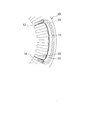
- FIG. 2A is a top view of stator core 20 at the stage of inserting interphase insulating paper 10 into stator core 20.
- FIG. 2A each of the axial direction, the radial direction, and the circumferential direction of the stator core 20 will be simply referred to as the axial direction, the radial direction, and the circumferential direction.
- the stator core 20 is a hollow cylindrical member, and the stator core 20 is provided with a plurality of slots 21 opening on the inner diameter side, and the space between the adjacent slots 21 is referred to as a tooth 23. That is, the stator core 20 is configured by arranging the teeth 23 extending radially inward in parallel in the circumferential direction. The coil 22 is wound around the teeth 23 in a state of being inserted so as to straddle the two slots 21.
- the interphase insulating paper 10 is set in the holder 32 of the insertion device 30.
- the holder 32 is a substantially U-shaped member which is curved so as to be opened radially outward as a whole, and a part of the radial tip is inserted into the slot 21. By doing this, the legs 13 and 14 of the interphase insulating paper 10 set on the holder 32 are inserted into the slot 21.
- the tip of the holder 32 is configured to be rounded in the circumferential direction. By doing so, even when the legs 13 and 14 come into contact with the holder 32, damage to the legs 13 and 14 can be suppressed.
- FIG. 2B is a cross-sectional view taken along the line A-A 'of FIG. 2A.
- the holder 32 of the insertion apparatus 30 is abbreviate
- interphase insulating paper 10 is moved with leg 14 inserted in slot 21. Then, when the entire leg 14 is inserted into the slot 21, the insertion device 30 ends the movement in the axial direction.
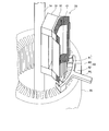
- FIG. 3 is a perspective view of the insertion device 30. As shown in FIG.
- the insertion device 30 is provided on the inner diameter of the stator core 20 on the projection plane in the axial direction, and is configured by the main body 31, the holder 32, the pressing portion 33, and the rail 34.
- the holder 32 is attached to the radial outside of the main body 31.
- the main body 31 and the pressing portion 33 are configured to be axially movable independently along the rail 34 extending in the axial direction.
- the main body 31 is configured to be axially movable along the rails 34, and the holder 32 is attached to the main body 31 radially outward.
- the main body 31 is configured by arranging the main body upper portion 31A, the main body middle portion 31B, and the main body lower portion 31C in parallel along the rails 34.
- the main body upper portion 31A and the main body lower portion 31C are provided so as to project outward in the radial direction with respect to the main body intermediate portion 31B, and are configured to be movable in the radial direction.
- the holder 32 is a U-shaped member that is curved so as to open radially outward, and is configured by axially arranging the upper holder portion 32A, the intermediate holder portion 32B, and the lower holder portion 32C in the axial direction.
- the upper holder portion 32A is connected to the upper body portion 31A
- the lower holder portion 32C is connected to the lower body portion 31C.
- the radially outer end of the holder middle portion 32B protrudes radially outward with respect to the ends of the upper holder 32A and the lower holder 32C.
- the holder middle portion 32B is not connected to the holder upper portion 32A and the holder lower portion 32C, but is connected to the main body middle portion 31B via a bridge (not shown), so the holder middle portion 32B does not move.
- the pressing portion 33 includes a pressing main portion 33A connected to the rail 34 and a pressing plate 33B.
- the pressing main body portion 33A is configured by two rectangular parallelepipeds having equal widths in the circumferential direction and different lengths in the radial direction, and a stepped portion 33C is provided in the radial direction.
- the end of the pressing plate 33B is connected to the step 33C.
- the pressing plate 33B is configured to be curved, and the inner diameter surface of the projection plane in the axial direction substantially faces the outer diameter surface of the holder 32.
- FIGS. 4A to 4E A process will be described in which a coil is inserted into a part of the slot 21 of the stator core 20 and the legs 13 and 14 of the interphase insulating paper 10 are inserted into the slot 21 into which the coil is inserted.
- the description of the coil is omitted because of the readability of the figure. Note that, in the following description, directions in the following description indicate directions (upper, lower, left, and right) in the drawings unless otherwise noted.
- FIG. 4A is a view showing a setting process of the interphase insulating paper 10.
- the radially inner surface of the pressing plate 33B is provided slightly radially outward of the radial outer surface of the holder 32.
- the interphase insulating paper 10 is attached to the radial outer surface of the holder 32, and when the pressing portion 33 is moved on the holder 32 along the axial direction, the interphase insulating paper 10 is fixed by the pressing plate 33B.
- the tip of holder 32 is provided in slot 21 on the projection plane in the axial direction.
- FIG. 4B is a diagram showing an axial insertion process in which interphase insulating paper 10 is axially inserted into slot 21 after the setting process. In this figure, a part of the vicinity of the end face of stator core 20 is shown enlarged.
- the main body 31 and the pressing portion 33 move along the rail 34 so as to approach the stator core 20 in the axial direction in an integrated state.
- the lower end of the interphase insulating paper 10 fixed on the holder 32 is inserted into the opening at the upper end of the slot 21.
- FIG. 4C is a diagram showing an axial insertion step in a state where the insertion device 30 is further moved in the axial direction than FIG. 4B and is inserted into the stator core 20. In this figure, a part of the vicinity of the end face of stator core 20 is shown enlarged.
- the main body 31 and the pressing portion 33 are further integrally inserted into the inner diameter of the stator core 20 below.
- the end portions of the leg portions 13 and 14 of the interphase insulating paper 10 are further inserted into the slot 21.
- FIG. 4D is a diagram showing an axial insertion step in which interphase insulating paper 10 is completely inserted into slot 21 by lowering insertion device 30 further than in FIG. 4C.
- the legs 13 and the legs 14 (not shown) are inserted into the slots 21 with the interphase insulating paper 10 attached to the holder 32.
- the insulating portion 11 is located above the slot 21 in the axial direction
- the insulating portion 12 is located below the slot 21 in the axial direction.
- FIG. 4E is a view showing a pressing portion removing step of removing the pressing portion 33 upward from the inner diameter of the stator core 20.
- FIG. 4E shows a view showing a pressing portion removing step of removing the pressing portion 33 upward from the inner diameter of the stator core 20.
- FIG. 4F is a view showing a radial insertion step of inserting the interphase insulating paper 10 in the radial direction with respect to the slot 21.
- FIG. 4G is a view showing an insertion device taking-out step of taking out the insertion device 30. As shown in FIG.
- the upper main body 31A and the lower main body 31C are moved to the radially inner initial position, and the main body 31 and the pressing portion 33 extend in the axial direction along the rail 34.
- the insertion device 30 is taken out of the stator core 20, and the insertion of the interphase insulating paper 10 into the slot 21 is completed.
- FIG. 4H is a top view of the slot 21 after the folding step.
- the circumferential center portions of the insulating portions 11 and 12 are bent radially outward and are curved so as to open radially inward.
- the legs 13 and 14 are rotated in the slot 21.
- the coil 22 is covered on the end face of the stator core 20, and the insulation between the phases is maintained.
- this folding step may be performed after the step of FIG. 4F. In that case, the upper main body 31A and the lower main body 31C of the insertion device 30 are further moved radially outward, and the insulating portions 11 and 12 are folded back radially outward.
- the holder 32 is configured in a U-shape extending in the axial direction and opening radially outward, and in the radially outer surface of the curved surface, the holder 32 The insulating paper 10 is held.
- the radial outer end of the holder 32 is arranged to be positioned in the slot 21 on the projection plane in the axial direction, and the holder 32 is configured to be movable in the slot 21 in the axial direction.
- the holder 32 is configured to be movable in the radial direction.
- the entire interphase insulating paper 10 is folded back radially outward and is opened radially inward.
- the central portions in the circumferential direction of the insulating portions 11 and 12 are bent radially outward, and are bent radially inward (FIG. 4G).
- the coil 22 is covered with the insulating portions 11 and 12 at the end face of the stator core 20, insulation between the phases can be maintained.
- the interphase insulating paper 10 is fixed such that the curved radially outer end is positioned outside the interphase insulating paper 10.
- the interphase insulating paper 10 in particular, the legs 13 and 14 are inserted into the slot 21 while being covered by the holder 32, the interphase insulating paper 10 collides with the teeth 23 The risk of damage can be reduced.
- the tip end of the holder 32 is formed to be rounded. By doing so, the possibility of the interphase insulating paper 10 being damaged due to the interphase insulating paper 10 colliding with the tip of the holder 32 can be reduced.
- the insertion device 30 further includes the pressing portion 33 that presses the interphase insulating paper 10 fixed to the holder 32 from the radial outer side. Since the interphase insulating paper 10 is fixed on the holder 32 by having such a pressing portion 33, it is possible to suppress the falling of the interphase insulating paper 10 when the holder 32 moves. Therefore, re-insertion of the interphase insulating paper 10 can be reduced, and the productivity of the motor can be improved.
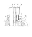
- FIG. 5A is a perspective view of interphase insulating paper 10 as viewed from the outer side in the radial direction in a state in which the insertion device 30 is lowered toward the stator core 20 in the axial direction.
- the holding part 33 is abbreviate
- FIG. 5B is a perspective view of interphase insulating paper 10 as viewed from the inner side in the same state as FIG. 5A.
- An insertion jig 40 is provided on the end face of the stator core 20 on the side where the interphase insulating paper 10 is inserted.
- the insertion jig 40 is composed of guides 41 and 42, a bridge 43 connecting the guides 41 and the guides 42, and a bar 44 connected to the bridge 43.
- the guides 41 and 42 are provided on the end face of the stator core 20 and have an opening through which the interphase insulating paper 10 can pass in the axial direction.
- the inner wall surfaces of the guides 41 and 42 are continuous with the inner surface of the slot 21 at the end face of the slot 21 and become wider in the direction away from the stator core 20. That is, the inner surfaces of the guides 41 and 42 are tapered in the direction toward the stator core 20, and the opening width is narrowed toward the lower portion.
- the guide 41 and the guide 42 are connected by a bridge 43 extending in the circumferential direction.
- a radially outwardly extending bar 44 is connected to a circumferential intermediate portion of the bridge 43.
- Interphase insulating paper 10 is guided to the upper end opening of slot 21 through guides 41, 42.
- the interphase insulating paper 10 is inserted into the slot 21, it is first inserted into the guides 41 and 42.
- the width of the opening on the side where the interphase insulating paper 10 is inserted is wider than the width of the slot 21. Therefore, since the interphase insulating paper 10 is first inserted into the opening on the upper end side of the guides 41 and 42 wider than the slot 21, the interphase insulating paper 10 collides with the teeth 23 and the guides 41 and 42. Is suppressed.
- the guides 41 and 42 are provided on the end face of the stator core 20 and configured such that the slots 21 and the inner surface are continuous and the radial opening becomes wider as the distance from the end face increases. Further, By providing such a guide, the slot insulating paper 50 is inserted into the guide 41, 42 after being inserted into the guide 41, 42 wider than the slot 21, and then is inserted into the slot 21 while being guided by the guides 41, 42.
- slot insulating paper 50 is provided in the slot 21 to insulate the slot 21 from the coil 22. Therefore, the interphase insulating paper 10 is inserted into the slot 21 in a state in which the slot insulating paper 50 is inserted.
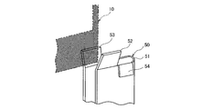
- FIG. 6 is a perspective view of the slot insulating paper of the present embodiment. Although the slot insulating paper is folded and disposed in the slot 21, the description of the slot 21 is omitted for the sake of explanation.
- the slot insulating paper 50 is inserted such that the rectangular main body 51 is bent into the slot 21, and the upper end thereof is provided outside the slot 21.
- the slot insulating paper 50 is partially exposed to the outside in the axial direction from the slot 21 and a fold line 50A is provided in the radial direction at the exposed portion.
- a portion of the slot insulating paper 50 inserted into the slot 21 below the folding line 50A is referred to as a main body 51.
- extension portions 52, 53 which are inclined and extend in the axial direction by being broken at the folding line 50A are provided.
- a folded portion 54 configured to be folded at a fold line 50A is provided at a position that is continuous with the extension portion 52 radially outward.
- the folded back portion 54 is folded 180 degrees at the fold line 50A, and is provided along the main body portion 51.
- the return part (not shown) is provided also so that the extension part 53 and radial outer side may be followed.
- the extension portions 52 and 53 are provided so as to open in the direction away from the main body 51 in the axial direction, that is, to be separated from each other in the axial direction starting from the connection portion with the main body 51.
- the radial openings are wider as the extensions 52 and 53 move away from the end face of the stator core 20. It is configured to be The interphase insulating paper 10 is inserted into the slot 21 with the extension portions 52 and 53 configured to be narrowed in the axial direction downward as such guides.
- FIG. 7 is a top view of the stator core 20 when the interphase insulating paper 10 is inserted in the present embodiment.
- the width of the opening is narrowed radially inward.
- the radial opening width d of the slot 21 is configured to be narrower than the width of the legs 13 and 14 of the interphase insulating paper 10.
- the legs 13 and 14 are less likely to protrude from the slot 21, thereby reducing the insertion failure of the interphase insulating paper 10. be able to.
- the width of the leg portions 13 and 14 is wider than the width of the radial inner opening of the slot 21.
- the interphase insulating paper 10 is inserted into the slot 21 in the axial direction from the end face of the stator core 20 in the insertion step after being made parallel to the side surface of the slot 21 in the bending step. Therefore, when the interphase insulating paper 10 is inserted into the slot 21, it is parallel to the side surface of the slot 21, so the legs 13 and 14 are inserted into the slot 21 without colliding with the teeth 24. It will be
- the legs 13 and 14 are narrower than the width of the opening of the slot 21 after the interphase insulating paper 10 is inserted into the slot 21, the legs 13 and 14 are prevented from jumping out of the slot 21 .
Landscapes
- Engineering & Computer Science (AREA)
- Power Engineering (AREA)
- Manufacturing & Machinery (AREA)
- Insulation, Fastening Of Motor, Generator Windings (AREA)
- Manufacture Of Motors, Generators (AREA)
Abstract
本発明のある態様によれば、ステータコアのスロットに相間絶縁紙を挿入する挿入装置を備えるステータの製造装置であって、相間絶縁紙は、2つの絶縁部と、該絶縁部それぞれの対向する辺の両端同士を接続する2つの帯状の脚部とを備える。挿入装置は、ステータコアの軸方向に沿って移動可能に構成される本体と、軸方向に延在するとともに径方向外側に開くU字状に湾曲して構成され、該湾曲した面の径方向外側にて前記相間絶縁紙を支持するホルダと、を備える。そして、ホルダの径方向外側の端部は、軸方向の投影面において、スロット内に位置する。
Description
本発明はステータの製造装置、ステータの製造方法、及び、ステータに関するものである。
3相で駆動する電動モータにおいては、モータの一部を構成するステータコアに、3相のそれぞれに相当するコイルが設けられている。このようなモータにおいては、3相のコイル同士がステータコアの端面にて絶縁するように、相間絶縁紙を設けることがある。
相間絶縁紙は、一般に、矩形状の紙の中央近傍に矩形の穴が設けられることにより、2つの矩形の絶縁部と、それらの絶縁部の端部同士を接続する帯状の2つの脚部とにより構成されている。このような相間絶縁紙は、脚部がスロット内に配置されると、2つの絶縁部がステータコアの端面に位置して各相のコイル同士を絶縁する。
例えば、JPS61-185046Aには、相間絶縁紙をステータコアに挿入する装置が開示されている。この装置によれば、砲弾状のホルダの外周面に相間絶縁紙をセットすると、ホルダをステータコアの内径に挿入する。ホルダには、ステータコアの径方向外側へ相間絶縁紙を押し出す押し出し機構が設けられており、押し出し機構によって径方向外側へと相間絶縁紙をスロットへ押し出す。このようにすることで、相間絶縁紙の脚部はスロットに挿入され、絶縁部はステータコアの端面上に設けられることになるので、各相のコイル同士を絶縁することができる。
JPS61-185046Aによれば、押し出し機構によって脚部をステータの径方向外側に移動させて、スロット内に挿入させる際に、脚部がティースにぶつかることがある。このような場合には、相間絶縁紙をスロットに正しく挿入されないので、相間絶縁紙の挿入を再度行う必要があり、ステータの生産性が低下するという課題がある。
本発明はこのような課題を解決するために発明されたもので、ステータの生産性の向上を目的とするものである。
本発明のある態様によれば、ステータコアのスロットに相間絶縁紙を挿入する挿入装置を備えるステータの製造装置であって、相間絶縁紙は、2つの絶縁部と、該絶縁部それぞれの対向する辺の両端同士を接続する2つの帯状の脚部とを備える。挿入装置は、ステータコアの軸方向に沿って移動可能に構成される本体と、軸方向に延在するとともに径方向外側に開くU字状に湾曲して構成され、該湾曲した面の径方向外側にて前記相間絶縁紙を支持するホルダと、を備える。そして、ホルダの径方向外側の端部は、軸方向の投影面において、スロット内に位置する。
本発明の実施形態、本発明の利点については、添付された図面を参照しながら以下に詳細に説明する。
本発明の第1実施形態の挿入装置について説明する。
図1は、挿入装置によって挿入される相間絶縁紙の平面図である。
この図によれば、相間絶縁紙10は、矩形状の紙に矩形状の開口を設けることで形成されており、2つの矩形の絶縁部11、12と、帯状の脚部13、14とにより構成されている。2つの絶縁部11、12の対向する辺のそれぞれの両端同士が、脚部13、14によって接続されている。なお、相間絶縁紙10は、以下では絶縁性の紙であるものとして説明するが、紙に限らず絶縁性であれば樹脂性のものであってもよい。
図2A、2Bは、相間絶縁紙10がステータコア20に挿入される状況の説明図である。ステータコア20は、電動モータの一部を構成するとともに、該電動モータはジェネレータとしても動作可能であるものとする。
図2Aは、相間絶縁紙10のステータコア20への挿入段階における、ステータコア20の上面図である。なお、以下の説明において、ステータコア20の軸方向、径方向、及び、周方向のそれぞれを、単に軸方向、径方向、及び、周方向と称するものとする。
ステータコア20は、中空の筒状の部材であって、ステータコア20には、内径側に開口するスロット21が複数設けられており、隣接するスロット21の間はティース23と称される。すなわち、ステータコア20は、径方向内側に延在するティース23が周方向に並設されることによって構成されている。コイル22は、2つのスロット21に跨るように挿入された状態でティース23に巻き回されている。
相間絶縁紙10は、挿入装置30のホルダ32にセットされている。なお、この図においては説明のため挿入装置30のホルダ32のみが示されているものとする。ホルダ32は、全体が径方向外側に開くように湾曲された略U字状の部材であり、径方向の先端の一部がスロット21内に挿入されている。このようにすることで、ホルダ32上にセットされた相間絶縁紙10の脚部13、14が、スロット21に挿入されている。
なお、ホルダ32の先端は、周方向に丸みを帯びて構成されている。このようにすることで、ホルダ32に脚部13、14が接触してしまった場合でも、脚部13、14の損傷を抑制することができる。
図2Bは、図2AのA-A’断面図である。なお、この図においては、可読性のために挿入装置30のホルダ32は省略されている。
ホルダ32(不図示)が軸方向(図面下方向、矢印方向)に移動されると、相間絶縁紙10は、脚部14がスロット21に挿入された状態で移動される。そして、脚部14の全体がスロット21に挿入されると、挿入装置30は軸方向の移動を終了する。
ここで、相間絶縁紙10をスロット21に挿入する挿入装置30の詳細について説明する。
図3は、挿入装置30の斜視図である。
挿入装置30は、軸方向の投影面においては、ステータコア20の内径に設けられており、本体31、ホルダ32、押さえ部33、及び、レール34により構成されている。ホルダ32は、本体31の径方向外側に取り付けられている。本体31、及び、押さえ部33は、軸方向に延在するレール34に沿って各々独立に軸方向に移動可能に構成されている。
本体31は、上述のように、レール34に沿って軸方向に移動可能に構成されており、本体31には、径方向外側にホルダ32が取り付けられている。
本体31は、本体上部31A、本体中間部31B、及び、本体下部31Cが、レール34に沿って並設することにより構成されている。本体上部31A、及び、本体下部31Cは、本体中間部31Bよりも径方向外側に突出するように設けられるとともに、径方向に移動可能に構成されている。
ホルダ32は、径方向外側に開くように湾曲するU字状の部材であり、ホルダ上部32A、ホルダ中間部32B、及び、ホルダ下部32Cが軸方向に並設することにより構成されている。ホルダ上部32Aは本体上部31Aに接続されるとともに、ホルダ下部32Cは本体下部31Cに接続されている。また、ホルダ中間部32Bの径方向外側の端部は、ホルダ上部32A、及び、ホルダ下部32Cの端部に対して、径方向外側に突出している。
本体上部31Aと本体下部31Cとが径方向外側に移動されると、ホルダ上部32Aとホルダ下部32Cとが径方向の外側に押し出される。なお、ホルダ中間部32Bは、ホルダ上部32A、及び、ホルダ下部32Cとは接続されず、本体中間部31Bと不図示のブリッジを介して接続されているので、ホルダ中間部32Bは移動しない。
押さえ部33は、レール34と接続される押さえ本体部33Aと、押さえ板33Bとにより構成されている。押さえ本体部33Aは、周方向に等幅で、径方向の長さが異なる2つの直方体により構成されており、径方向に段部33Cが設けられている。段部33Cには、押さえ板33Bの端部が接続されている。押さえ板33Bは、湾曲するとともに、軸方向の投影面における内径面が、ホルダ32の外径面と略対向するように構成されている。
次に、図4Aから図4Eまでを用いて、ステータコア20に相間絶縁紙10が挿入される挿入方法について説明する。なお、ステータコア20のスロット21の一部にコイルが挿入されており、そのコイルが挿入されているスロット21に相間絶縁紙10の脚部13、14が挿入される工程について説明する。以下では、図の可読性のため、コイルの記載は省略している。なお、特に断りがない限り、以下の説明における方向は、図面における方向(上下左右)を示すものとする。
図4Aは、相間絶縁紙10のセット工程を示す図である。
上述のように、軸方向の投影面においては、押さえ板33Bの径方向内側の一面は、ホルダ32の径方向外側の面よりもわずかに径方向外側に設けられている。ホルダ32の径方向外側の面に相間絶縁紙10が取り付けられ、押さえ部33が軸方向に沿ってホルダ32の上に移動されると、相間絶縁紙10が押さえ板33Bによって固定される。なお、この状態におけるステータコア20の上面図は、図2Aに示したとおり、軸方向の投影面においてホルダ32の先端がスロット21内に設けられていることになる。
図4Bは、セット工程の後において、相間絶縁紙10がスロット21に軸方向に挿入される軸方向挿入工程を示す図である。この図においては、ステータコア20の端面の近傍の一部が拡大されて示されている。
この図においては、本体31と押さえ部33とが、一体となった状態でレール34に沿って軸方向にステータコア20に近づくように移動する。このようにすると、ホルダ32上にて固定された相間絶縁紙10の下端がスロット21の上端の開口に挿入される。
図4Cは、図4Bよりも挿入装置30がさらに軸方向に移動して、ステータコア20に挿入された状態における、軸方向挿入工程を示す図である。この図においては、ステータコア20の端面の近傍の一部が拡大されて示されている。
この図においては、さらに、本体31と押さえ部33とが一体となって、ステータコア20の内径にさらに下方に挿入される。このようにすることで、相間絶縁紙10の脚部13、14の端部が、さらに、スロット21へと挿入される。
図4Dは、図4Cよりもさらに挿入装置30を下降させることで、相間絶縁紙10が完全にスロット21に挿入された状態となる軸方向挿入工程を示す図である。この図によれば、相間絶縁紙10はホルダ32に取り付けられた状態で、脚部13、及び、脚部14(不図示)がスロット21に挿入されている。なお、この状態においては、絶縁部11は、スロット21の軸方向上方に位置し、絶縁部12は、スロット21の軸方向下方に位置する。
図4Eは、押さえ部33をステータコア20の内径から上方へと抜き取る、押さえ部抜き取り工程を示す図である。この図に示されるように、本体31を固定させた状態で、押さえ部33のみを軸方向にステータコア20から遠ざかるように上方に移動させると、押さえ部33がステータコア20から抜き取られる。
図4Fは、相間絶縁紙10をスロット21に対して径方向に挿入する径方向挿入工程を示す図である。
本体上部31A、及び、本体下部31Cが径方向外側に移動されると、ホルダ上部32A、及び、ホルダ下部32Cが径方向外側に移動される。このようにすると、絶縁部11、12が径方向外側に移動されるとともに、脚部13、14は、スロット21にさらに径方向外側へと挿入される。
図4Gは、挿入装置30を取り出す挿入装置取出工程を示す図である。
スロット21に相間絶縁紙10が挿入されると、本体上部31A、及び、本体下部31Cが径方向内側の初期位置に移動され、そして、本体31及び押さえ部33は、レール34に沿って軸方向にステータコア20から上昇して離れるように移動される。このようにして、挿入装置30がステータコア20から取り出され、相間絶縁紙10のスロット21への挿入が完了される。
なお、図4Gの工程の後に、絶縁部11、12を周方向の外側に移動させて、相間絶縁紙10の全体を径方向外側に折り返す折り返し工程を行ってもよい。図4Hは、折り返し工程後のスロット21の上面図である。
この図によれは、絶縁部11、12の周方向の中央部が径方向外側へと折れ曲がり、径方向内側に開くように湾曲した状態となる。なお、この状態では、脚部13、14は、スロット21内にて回転して、このようにすることで、ステータコア20の端面においてコイル22が覆われて相間の絶縁が保たれる。
なお、この折り返し工程は、図4Fの工程の後に行われてもよい。その場合には、挿入装置30の本体上部31A、本体下部31Cが、径方向外側にさらに移動して、絶縁部11、12を径方向外側へと折り返すことになる。
第1実施形態によれば、以下の効果を得ることができる。
第1実施形態のステータの製造装置によれば、ホルダ32は、軸方向に延在するとともに径方向外側に開くU字状に構成されており、その湾曲した面の径方向外側の面に相間絶縁紙10が保持される。そして、ホルダ32の径方向外側の端部は、軸方向の投影面においてスロット21内に位置するように配置されるとともに、ホルダ32が軸方向にスロット21内に移動可能に構成されている。
ここで、ホルダ32が、相間絶縁紙10を径方向外側の面にて固定した状態で、軸方向に移動してステータコア20の内径側に到達すると、ホルダ32の径方向外側の端部、及び、ホルダ32により保持される相間絶縁紙10の脚部13、14は、ティース23と衝突することなく、スロット21内に挿入される。このようにすることで、従来の方法よりも確実に脚部13、14をスロット21に挿入することができるので、相間絶縁紙10の挿入のやり直しが低減し、ステータの生産性を向上することができる。
第1実施形態のステータの製造装置によれば、ホルダ32は、径方向に移動できるように構成されている。相間絶縁紙10がステータコア20のスロット21に挿入された後にさらに、ホルダ32が径方向外側に移動すると、相間絶縁紙10は、全体が径方向外側へと折り返され、径方向内側に開く状態となる。すなわち、絶縁部11、12の周方向の中央部が径方向外側に折れ曲がり、径方向内側に湾曲した状態となる(図4G)。このようにすることで、ステータコア20の端面において、コイル22が絶縁部11、12により覆われるので、相間の絶縁を保つことができる。このような折り返し工程を、挿入装置30を用いて行うことにより、折り返しを行う別の装置が不要になるので、ステータの生産性を向上することができる。
第1実施形態のステータの製造装置によれば、ホルダ32においては、湾曲した径方向外側端が相間絶縁紙10よりも外側に位置するように、相間絶縁紙10が固定される。このような構成となることにより、相間絶縁紙10、特に、脚部13、14は、ホルダ32に覆われた状態でスロット21に挿入されるので、相間絶縁紙10がティース23と衝突して損傷するおそれを低減できる。
第1実施形態のステータの製造装置によれば、ホルダ32の先端部は丸みを帯びて形成されている。このようにすることで、相間絶縁紙10がホルダ32の先端部と衝突して相間絶縁紙10の損傷するおそれを低減できる。
第1実施形態のステータの製造装置によれば、挿入装置30は、ホルダ32に固定される相間絶縁紙10を、径方向外側から押さえる押さえ部33をさらに備える。このような押さえ部33を有することにより、ホルダ32の上にて相間絶縁紙10が固定されるので、ホルダ32の移動時に相間絶縁紙10の落下を抑制できる。そのため、相間絶縁紙10の挿入のやり直しが低減し、モータの生産性を向上することができる。
(第2実施形態)
第1実施形態においては、ステータコア20の端面からスロット21に相間絶縁紙10を軸方向から直接挿入する例について説明した。第2実施形態においては、ステータコア20の端面にガイドを設け、ガイドを介してスロット21に軸方向から相間絶縁紙10を挿入する例について説明する。
第1実施形態においては、ステータコア20の端面からスロット21に相間絶縁紙10を軸方向から直接挿入する例について説明した。第2実施形態においては、ステータコア20の端面にガイドを設け、ガイドを介してスロット21に軸方向から相間絶縁紙10を挿入する例について説明する。
図5Aは、挿入装置30が軸方向にステータコア20に向けて下降した状態における、相間絶縁紙10を径方向外側から見た斜視図である。なお、この図においては、説明のために押さえ部33が省略されている。
図5Bは、図5Aと同じ状態において、相間絶縁紙10を径方内側から見た斜視図である。
ステータコア20における相間絶縁紙10が挿入される側の端面には、挿入治具40が設けられている。挿入治具40は、ガイド41、42と、ガイド41とガイド42とを接続するブリッジ43と、ブリッジ43と接続されるバー44と、により構成されている。
ガイド41、42は、ステータコア20の端面上に設けられており、相間絶縁紙10が軸方向に通過できる開口を備える。ガイド41、42の内壁面は、スロット21の端面においてスロット21の内面と連続するとともに、ステータコア20から離れる方向に幅広となる。すなわち、ガイド41、42の内面は、ステータコア20に向かう方向にテーパ状であり、下部ほど開口幅が狭くなるように構成されている。
ガイド41とガイド42とは、周方向に延在するブリッジ43によって接続されている。ブリッジ43の周方向の中間部には、径方向外側に延在するバー44が接続されている。
相間絶縁紙10は、ガイド41、42を通じて、スロット21の上端開口へと誘導される。相間絶縁紙10をスロット21に挿入する場合には、まず、ガイド41、42に挿入される。ここで、ガイド41、42において軸方向の2つの開口のうち、相間絶縁紙10が挿入される側の開口の幅はスロット21の幅より広い。そのため、相間絶縁紙10は、まず、スロット21よりも幅の広いガイド41、42の上端側の開口に挿入されることになるので、相間絶縁紙10がティース23やガイド41、42と衝突することが抑制される。
第2実施形態によれば、以下の効果を得ることができる。
第2実施形態のステータの製造装置によれば、ステータコア20の端面に設けられ、スロット21と内面が連続するとともに、端面から遠ざかるほど径方向の開口が広くなるように構成されるガイド41、42を、さらに備える。このようなガイドを備えることにより、スロット絶縁紙50は、スロット21よりも幅広なガイド41、42に挿入された後に、ガイド41、42によってガイドされて、スロット21に挿入される。
そのため、相間絶縁紙10が、スロット21に挿入される際に、ティース23と衝突することが抑制されるので、相間絶縁紙10の挿入のやり直しが低減し、モータの生産性を向上することができる。
(第2実施形態の変形例)
上述の実施形態においては、ステータコア20の端面にガイド41、42を設ける例について説明した。以下では、スロット21にスロット絶縁紙50が設けられており、スロット絶縁紙がガイド41、42と同等の機能を備える変形例について説明する。
上述の実施形態においては、ステータコア20の端面にガイド41、42を設ける例について説明した。以下では、スロット21にスロット絶縁紙50が設けられており、スロット絶縁紙がガイド41、42と同等の機能を備える変形例について説明する。
一般に、スロット21内には、スロット21とコイル22とを絶縁するために、スロット絶縁紙50が設けられている。そのため、相間絶縁紙10は、スロット絶縁紙50が挿入された状態のスロット21に挿入されることになる。
図6は、本実施形態のスロット絶縁紙の斜視図である。なお、スロット絶縁紙はスロット21内にて折り曲げられて配置されているが、説明のためスロット21の記載は省略する。
スロット絶縁紙50は、矩形状の本体部51がスロット21内に折れ曲がるように挿入されており、その上端がスロット21外に設けられている。スロット絶縁紙50は、スロット21から軸方向外側に一部が露出するとともに、その露出部において径方向に折り線50Aが設けられている。ここで、スロット絶縁紙50において折り線50Aよりも下方にてスロット21に挿入されている部分を、本体部51と称するものとする。
本体部51の径方向内側の2箇所の端部には、折り線50Aにて折られることで軸方向に傾斜して延在する延長部52、53が設けられている。また、延長部52と径方向外側に連続する位置には、折り線50Aにて折り返して構成された折り返し部54が設けられている。折り返し部54は、折り線50Aにて180度折り返されており、本体部51と沿うように設けられている。なお、延長部53と径方向外側に連続するようにも折り返し部(不図示)が設けられている。
延長部52、53は、軸方向において本体部51から遠ざかる方向に開くように、すなわち、本体部51との接続部分を起点として軸方向に互いに離れるように設けられている。このような構成となることで、相間絶縁紙10がスロット21に挿入される時には、延長部52、53がガイドとなるため、スロット21に衝突することなく相間絶縁紙10をスロット21に挿入することができる。
第2実施形態の変形例によれば、以下の効果を得ることができる。
第2実施形態の変形例のスロット絶縁紙50によれば、スロット絶縁紙50がスロット21に挿入されている状態で、延長部52、53がステータコア20の端面から遠ざかるほど径方向の開口が広くなるように構成されている。このような軸方向下方に幅が狭くなるように構成された延長部52、53がガイドとなって、相間絶縁紙10がスロット21に挿入される。
そのため、相間絶縁紙10が、スロット21に挿入される際に、ティース23と衝突することが抑制されるので、相間絶縁紙10の挿入のやり直しが低減し、モータの生産性を向上することができる。
(第3実施形態)
第1及び第2実施形態においては、ステータコア20のスロット21の開口が径方向に略等幅である例について説明した。本実施形態では、ティース23に突起部23Aが設けられており、スロット21の一部において径方向の開口の幅が狭くなっている例について説明する。
第1及び第2実施形態においては、ステータコア20のスロット21の開口が径方向に略等幅である例について説明した。本実施形態では、ティース23に突起部23Aが設けられており、スロット21の一部において径方向の開口の幅が狭くなっている例について説明する。
図7は、本実施形態において、相間絶縁紙10が挿入される場合のステータコア20の上面図である。
この図によれば、ティース23において、径方向内側の端部に周方向に突出する突起部23Aが設けられている。そのため、スロット21において、径方向内側にて開口の幅が狭くなっている。なお、スロット21の径方向の開口幅dは、相間絶縁紙10の脚部13、14の幅よりも狭くなるように構成されている。
このように、スロット21の径方向の開口幅dは、脚部13、14の幅よりも狭いため、脚部13、14がスロット21から飛び出にくくなり、相間絶縁紙10の挿入不良を低減することができる。
第3実施形態によれば、以下の効果を得ることができる。
第3実施形態のステータの製造方法によれば、脚部13、14の幅は、スロット21の径方向内側の開口の幅よりも広い。ここで、相間絶縁紙10は、湾曲ステップによってスロット21の側面と平行な状態とされた状態とされた後に、挿入ステップによってステータコア20の端面から軸方向にスロット21に挿入される。そのため、相間絶縁紙10は、スロット21に挿入される時には、スロット21の側面と平行な状態となっているので、脚部13、14は、ティース24と衝突することなく、スロット21に挿入されることになる。
また、相間絶縁紙10がスロット21に挿入された後には、脚部13、14の幅がスロット21の開口の幅よりも狭いので、脚部13、14がスロット21から飛び出るのが抑制される。
以上、本発明の実施形態について説明したが、上記実施形態は本発明の適用例の一部を示したに過ぎず、本発明の技術的範囲を上記実施形態の具体的構成に限定する趣旨ではない。また、上記実施形態は、適宜組み合わせ可能である。
Claims (9)
- ステータコアのスロットに相間絶縁紙を挿入する挿入装置を備えるステータの製造装置であって、
前記相間絶縁紙は、2つの絶縁部と、該絶縁部それぞれの対向する辺の両端同士を接続する2つの帯状の脚部とを備え、
前記挿入装置は、
前記ステータコアの軸方向に沿って移動可能に構成される本体と、
軸方向に延在するとともに径方向外側に開くU字状に湾曲して構成され、該湾曲した面の径方向外側にて前記相間絶縁紙を支持するホルダと、を備え、
前記ホルダの径方向外側の端部は、軸方向の投影面において、前記スロット内に位置する、ステータの製造装置。 - 請求項1に記載のステータの製造装置であって、
前記ホルダは、径方向に移動可能に構成されている、ステータの製造装置。 - 請求項1または2に記載のステータの製造装置であって、
前記ホルダは、前記湾曲した面内にて前記相間絶縁紙を支持する、ステータの製造装置。 - 請求項1から3のいずれか1項に記載のステータの製造装置であって、
前記ホルダの径方向の先端部は丸みを帯びて形成されている、ステータの製造装置。 - 請求項1から4のいずれか1項に記載のステータの製造装置であって、
前記挿入装置は、
前記ホルダに支持される前記相間絶縁紙を、径方向外側から押さえる押さえ部を、さらに備え、
前記押さえ部は、前記本体とは独立して軸方向に移動可能に構成される、ステータの製造装置。 - 請求項1から5のいずれか1項に記載のステータの製造装置であって、
前記挿入装置は、
前記ステータコアの軸方向の端面に設けられ、前記スロットと内面が連続するとともに、前記端面から軸方向に遠ざかるほど径方向の開口幅が広くなるように構成されるガイドを、さらに備える、ステータの製造装置。 - ホルダに支持された相間絶縁紙を、ステータコアのスロットに挿入することにより、ステータを製造する製造方法であって、
前記相間絶縁紙は、2つの絶縁部と、前記絶縁部それぞれの対向する辺の両端同士を接続する2つの帯状の脚部と、を備え、
前記ホルダは、前記ステータコアの軸方向に移動可能に構成され、
前記製造方法は、
前記相間絶縁紙を、前記ホルダにおいて湾曲させるとともに、径方向外側の端部にて前記脚部が軸方向の投影面において前記スロット内に位置するように保持し、
前記ホルダを、軸方向に移動させて前記ステータコアの内部に挿入する、製造方法。 - 請求項7に記載のステータの製造方法であって、
前記脚部の幅は、前記スロットの径方向内側の開口の幅よりも広く設定される、ステータの製造方法。 - スロットを備えるステータコアと、該スロットに挿入される相間絶縁紙とを有するステータであって、
前記相間絶縁紙は、
2つの絶縁部と、
前記絶縁部それぞれの対向する辺の両端同士を接続する2つの帯状の脚部と、を備え、
前記スロットの径方向内側の開口幅は、前記脚部の幅よりも狭い、ステータ。
Priority Applications (2)
| Application Number | Priority Date | Filing Date | Title |
|---|---|---|---|
| JP2019524729A JP6711460B2 (ja) | 2017-06-19 | 2017-06-19 | ステータの製造装置、ステータの製造方法、及び、ステータ |
| PCT/JP2017/022576 WO2018235142A1 (ja) | 2017-06-19 | 2017-06-19 | ステータの製造装置、ステータの製造方法、及び、ステータ |
Applications Claiming Priority (1)
| Application Number | Priority Date | Filing Date | Title |
|---|---|---|---|
| PCT/JP2017/022576 WO2018235142A1 (ja) | 2017-06-19 | 2017-06-19 | ステータの製造装置、ステータの製造方法、及び、ステータ |
Publications (1)
| Publication Number | Publication Date |
|---|---|
| WO2018235142A1 true WO2018235142A1 (ja) | 2018-12-27 |
Family
ID=64735558
Family Applications (1)
| Application Number | Title | Priority Date | Filing Date |
|---|---|---|---|
| PCT/JP2017/022576 Ceased WO2018235142A1 (ja) | 2017-06-19 | 2017-06-19 | ステータの製造装置、ステータの製造方法、及び、ステータ |
Country Status (2)
| Country | Link |
|---|---|
| JP (1) | JP6711460B2 (ja) |
| WO (1) | WO2018235142A1 (ja) |
Citations (3)
| Publication number | Priority date | Publication date | Assignee | Title |
|---|---|---|---|---|
| JP2005110417A (ja) * | 2003-09-30 | 2005-04-21 | Toyota Motor Corp | 相間絶縁紙およびその製造方法 |
| JP2007037330A (ja) * | 2005-07-28 | 2007-02-08 | Aisin Aw Co Ltd | 相間絶縁紙組み付け治具 |
| JP2007104785A (ja) * | 2005-10-03 | 2007-04-19 | Toyota Motor Corp | 相間絶縁紙の組み付け方法および装置 |
-
2017
- 2017-06-19 WO PCT/JP2017/022576 patent/WO2018235142A1/ja not_active Ceased
- 2017-06-19 JP JP2019524729A patent/JP6711460B2/ja active Active
Patent Citations (3)
| Publication number | Priority date | Publication date | Assignee | Title |
|---|---|---|---|---|
| JP2005110417A (ja) * | 2003-09-30 | 2005-04-21 | Toyota Motor Corp | 相間絶縁紙およびその製造方法 |
| JP2007037330A (ja) * | 2005-07-28 | 2007-02-08 | Aisin Aw Co Ltd | 相間絶縁紙組み付け治具 |
| JP2007104785A (ja) * | 2005-10-03 | 2007-04-19 | Toyota Motor Corp | 相間絶縁紙の組み付け方法および装置 |
Also Published As
| Publication number | Publication date |
|---|---|
| JP6711460B2 (ja) | 2020-06-17 |
| JPWO2018235142A1 (ja) | 2019-11-07 |
Similar Documents
| Publication | Publication Date | Title |
|---|---|---|
| KR102905676B1 (ko) | 확장과 비틀림을 위한 장치 및 방법 | |
| US11063482B2 (en) | Stator and motor having the same | |
| JP3741600B2 (ja) | 電動機の固定子 | |
| US10305355B2 (en) | Stator manufacturing method and coil | |
| KR102688104B1 (ko) | 구동모터용 터미널 어셈블리 | |
| JP5677530B2 (ja) | 回転電機の固定子巻線、回転電機の固定子、回転電機の固定子の製造方法、及び回転電機の固定子の製造に用いる治具 | |
| US7084541B2 (en) | Stator coil made of joined conductor segments for rotary electric machinery and method for manufacturing the same | |
| JP6358086B2 (ja) | ステータ組立装置及びステータ組立方法 | |
| JP7478152B2 (ja) | モーター | |
| KR20160071374A (ko) | 다이나모 전기 기계의 부품을 제조하기 위한 장치 및 방법 | |
| US9887601B2 (en) | Stator of rotary electric machine | |
| US8127430B2 (en) | Method of assembling split core type stator of inner rotor type rotary electric machine | |
| JP2018026964A (ja) | 固定子及びそれを備えた回転電機 | |
| JP2015231277A (ja) | 回転電機のステータとその製造方法及び製造装置 | |
| US6744168B2 (en) | Stator and stator manufacturing method | |
| JP2000217293A (ja) | 回転電機 | |
| WO2019189934A1 (ja) | 絶縁シートの位置ずれ防止方法及び絶縁シートの位置ずれ防止装置 | |
| JP5813359B2 (ja) | 回転電機 | |
| KR20240084261A (ko) | 모터의 스테이터 | |
| JP2019004662A (ja) | カフスサポータ、相間絶縁紙、及びモータの製造方法 | |
| WO2018235142A1 (ja) | ステータの製造装置、ステータの製造方法、及び、ステータ | |
| JP2004179498A (ja) | コイルボビン構造 | |
| JP2009213343A (ja) | ステータ | |
| JP2014090532A (ja) | 回転電機のステータ | |
| JP2017077125A (ja) | 回転電機のステータ |
Legal Events
| Date | Code | Title | Description |
|---|---|---|---|
| 121 | Ep: the epo has been informed by wipo that ep was designated in this application |
Ref document number: 17914560 Country of ref document: EP Kind code of ref document: A1 |
|
| ENP | Entry into the national phase |
Ref document number: 2019524729 Country of ref document: JP Kind code of ref document: A |
|
| NENP | Non-entry into the national phase |
Ref country code: DE |
|
| 122 | Ep: pct application non-entry in european phase |
Ref document number: 17914560 Country of ref document: EP Kind code of ref document: A1 |