WO2018230205A1 - 通信装置、通信方法、及びプログラム - Google Patents
通信装置、通信方法、及びプログラム Download PDFInfo
- Publication number
- WO2018230205A1 WO2018230205A1 PCT/JP2018/018081 JP2018018081W WO2018230205A1 WO 2018230205 A1 WO2018230205 A1 WO 2018230205A1 JP 2018018081 W JP2018018081 W JP 2018018081W WO 2018230205 A1 WO2018230205 A1 WO 2018230205A1
- Authority
- WO
- WIPO (PCT)
- Prior art keywords
- terminal device
- information
- communication
- base station
- random access
- Prior art date
Links
- 238000004891 communication Methods 0.000 title claims abstract description 247
- 238000000034 method Methods 0.000 title claims abstract description 170
- 230000004044 response Effects 0.000 claims abstract description 93
- 230000005540 biological transmission Effects 0.000 claims description 244
- 238000005259 measurement Methods 0.000 claims description 32
- 238000012545 processing Methods 0.000 description 79
- 230000011664 signaling Effects 0.000 description 44
- 230000006870 function Effects 0.000 description 32
- 238000010586 diagram Methods 0.000 description 29
- 238000007726 management method Methods 0.000 description 26
- 230000008569 process Effects 0.000 description 22
- 238000005516 engineering process Methods 0.000 description 13
- 238000001514 detection method Methods 0.000 description 12
- 238000013507 mapping Methods 0.000 description 12
- 230000002776 aggregation Effects 0.000 description 11
- 238000004220 aggregation Methods 0.000 description 11
- 238000006243 chemical reaction Methods 0.000 description 8
- 230000010267 cellular communication Effects 0.000 description 7
- 230000007274 generation of a signal involved in cell-cell signaling Effects 0.000 description 6
- 238000013468 resource allocation Methods 0.000 description 6
- 101000741965 Homo sapiens Inactive tyrosine-protein kinase PRAG1 Proteins 0.000 description 5
- 102100038659 Inactive tyrosine-protein kinase PRAG1 Human genes 0.000 description 5
- 241000700159 Rattus Species 0.000 description 5
- 230000000694 effects Effects 0.000 description 5
- 101150096310 SIB1 gene Proteins 0.000 description 4
- 230000003321 amplification Effects 0.000 description 4
- 125000004122 cyclic group Chemical group 0.000 description 4
- 230000009977 dual effect Effects 0.000 description 4
- 238000012544 monitoring process Methods 0.000 description 4
- 238000003199 nucleic acid amplification method Methods 0.000 description 4
- 238000011156 evaluation Methods 0.000 description 3
- 239000000284 extract Substances 0.000 description 3
- 238000005070 sampling Methods 0.000 description 3
- 230000007704 transition Effects 0.000 description 3
- 101150039363 SIB2 gene Proteins 0.000 description 2
- 238000004364 calculation method Methods 0.000 description 2
- 238000012937 correction Methods 0.000 description 2
- 230000010354 integration Effects 0.000 description 2
- 230000007774 longterm Effects 0.000 description 2
- 230000001151 other effect Effects 0.000 description 2
- 230000000737 periodic effect Effects 0.000 description 2
- 230000010363 phase shift Effects 0.000 description 2
- 238000007670 refining Methods 0.000 description 2
- 238000010187 selection method Methods 0.000 description 2
- 239000004065 semiconductor Substances 0.000 description 2
- 238000000926 separation method Methods 0.000 description 2
- 230000005236 sound signal Effects 0.000 description 2
- 238000012546 transfer Methods 0.000 description 2
- 230000001133 acceleration Effects 0.000 description 1
- 230000006399 behavior Effects 0.000 description 1
- 230000001413 cellular effect Effects 0.000 description 1
- 230000008859 change Effects 0.000 description 1
- 230000000295 complement effect Effects 0.000 description 1
- 239000006185 dispersion Substances 0.000 description 1
- 150000002343 gold Chemical class 0.000 description 1
- PCHJSUWPFVWCPO-UHFFFAOYSA-N gold Chemical group [Au] PCHJSUWPFVWCPO-UHFFFAOYSA-N 0.000 description 1
- 239000004973 liquid crystal related substance Substances 0.000 description 1
- 229910044991 metal oxide Inorganic materials 0.000 description 1
- 150000004706 metal oxides Chemical class 0.000 description 1
- 238000010295 mobile communication Methods 0.000 description 1
- 238000012986 modification Methods 0.000 description 1
- 230000004048 modification Effects 0.000 description 1
- 239000013307 optical fiber Substances 0.000 description 1
- 230000002085 persistent effect Effects 0.000 description 1
- 238000004904 shortening Methods 0.000 description 1
- 238000001774 stimulated Raman spectroscopy Methods 0.000 description 1
Images


Classifications
-
- H—ELECTRICITY
- H04—ELECTRIC COMMUNICATION TECHNIQUE
- H04W—WIRELESS COMMUNICATION NETWORKS
- H04W74/00—Wireless channel access
- H04W74/08—Non-scheduled access, e.g. ALOHA
- H04W74/0833—Random access procedures, e.g. with 4-step access
- H04W74/0841—Random access procedures, e.g. with 4-step access with collision treatment
-
- H—ELECTRICITY
- H04—ELECTRIC COMMUNICATION TECHNIQUE
- H04B—TRANSMISSION
- H04B7/00—Radio transmission systems, i.e. using radiation field
- H04B7/02—Diversity systems; Multi-antenna system, i.e. transmission or reception using multiple antennas
- H04B7/04—Diversity systems; Multi-antenna system, i.e. transmission or reception using multiple antennas using two or more spaced independent antennas
- H04B7/06—Diversity systems; Multi-antenna system, i.e. transmission or reception using multiple antennas using two or more spaced independent antennas at the transmitting station
- H04B7/0686—Hybrid systems, i.e. switching and simultaneous transmission
- H04B7/0695—Hybrid systems, i.e. switching and simultaneous transmission using beam selection
-
- H—ELECTRICITY
- H04—ELECTRIC COMMUNICATION TECHNIQUE
- H04L—TRANSMISSION OF DIGITAL INFORMATION, e.g. TELEGRAPHIC COMMUNICATION
- H04L5/00—Arrangements affording multiple use of the transmission path
- H04L5/003—Arrangements for allocating sub-channels of the transmission path
- H04L5/0048—Allocation of pilot signals, i.e. of signals known to the receiver
-
- H—ELECTRICITY
- H04—ELECTRIC COMMUNICATION TECHNIQUE
- H04L—TRANSMISSION OF DIGITAL INFORMATION, e.g. TELEGRAPHIC COMMUNICATION
- H04L5/00—Arrangements affording multiple use of the transmission path
- H04L5/003—Arrangements for allocating sub-channels of the transmission path
- H04L5/0053—Allocation of signaling, i.e. of overhead other than pilot signals
-
- H—ELECTRICITY
- H04—ELECTRIC COMMUNICATION TECHNIQUE
- H04W—WIRELESS COMMUNICATION NETWORKS
- H04W16/00—Network planning, e.g. coverage or traffic planning tools; Network deployment, e.g. resource partitioning or cells structures
- H04W16/24—Cell structures
- H04W16/28—Cell structures using beam steering
-
- H—ELECTRICITY
- H04—ELECTRIC COMMUNICATION TECHNIQUE
- H04W—WIRELESS COMMUNICATION NETWORKS
- H04W24/00—Supervisory, monitoring or testing arrangements
- H04W24/08—Testing, supervising or monitoring using real traffic
-
- H—ELECTRICITY
- H04—ELECTRIC COMMUNICATION TECHNIQUE
- H04W—WIRELESS COMMUNICATION NETWORKS
- H04W72/00—Local resource management
- H04W72/04—Wireless resource allocation
- H04W72/044—Wireless resource allocation based on the type of the allocated resource
- H04W72/0446—Resources in time domain, e.g. slots or frames
-
- H—ELECTRICITY
- H04—ELECTRIC COMMUNICATION TECHNIQUE
- H04W—WIRELESS COMMUNICATION NETWORKS
- H04W72/00—Local resource management
- H04W72/20—Control channels or signalling for resource management
- H04W72/23—Control channels or signalling for resource management in the downlink direction of a wireless link, i.e. towards a terminal
- H04W72/232—Control channels or signalling for resource management in the downlink direction of a wireless link, i.e. towards a terminal the control data signalling from the physical layer, e.g. DCI signalling
-
- H—ELECTRICITY
- H04—ELECTRIC COMMUNICATION TECHNIQUE
- H04W—WIRELESS COMMUNICATION NETWORKS
- H04W74/00—Wireless channel access
- H04W74/04—Scheduled access
- H04W74/06—Scheduled access using polling
-
- H—ELECTRICITY
- H04—ELECTRIC COMMUNICATION TECHNIQUE
- H04L—TRANSMISSION OF DIGITAL INFORMATION, e.g. TELEGRAPHIC COMMUNICATION
- H04L5/00—Arrangements affording multiple use of the transmission path
- H04L5/0001—Arrangements for dividing the transmission path
- H04L5/0014—Three-dimensional division
- H04L5/0023—Time-frequency-space
-
- H—ELECTRICITY
- H04—ELECTRIC COMMUNICATION TECHNIQUE
- H04W—WIRELESS COMMUNICATION NETWORKS
- H04W74/00—Wireless channel access
- H04W74/08—Non-scheduled access, e.g. ALOHA
- H04W74/0833—Random access procedures, e.g. with 4-step access
Definitions
- the present disclosure relates to a communication device, a communication method, and a program.
- LTE Long Term Evolution
- LTE-A Long Term Evolution
- LTE-A Pro Long Term Evolution Pro
- NR New Radio
- NRAT New Radio Access Technology
- EUTRA Evolved Universal Terrestrial Radio Access
- FEUTRA Further EUTRA
- LTE includes LTE-A, LTE-A Pro, and EUTRA
- NR includes NRAT and FEUTRA.
- the base station apparatus (base station) is eNodeB (evolved NodeB), in NR, the base station apparatus (base station) is gNodeB, and in LTE and NR, the terminal apparatus (mobile station, mobile station apparatus, terminal) is UE (User Equipment). Also called.
- LTE and NR are cellular communication systems in which a plurality of areas covered by a base station apparatus are arranged in a cell shape. A single base station apparatus may manage a plurality of cells.
- NR is RAT (Radio Access Technology) different from LTE as a next-generation radio access method for LTE.
- NR is an access technology that can support various use cases including eMBB (Enhanced mobile broadband), mMTC (Massive machine type communications) and URLLC (Ultra reliable and low latency communications).
- eMBB Enhanced mobile broadband
- mMTC Massive machine type communications
- URLLC Ultra reliable and low latency communications
- NR performs beamforming for purposes such as coverage expansion and high-quality communication.
- a high-quality link can be provided by aligning transmission / reception beams of the base station apparatus and the terminal apparatus in appropriate directions. Since an appropriate beam changes in accordance with movement of the terminal device or change in channel quality, beam adjustment (Beam management) is performed between the base station device and the terminal device each time. Details of beam adjustment are disclosed in Non-Patent Document 1, for example.
- the present disclosure proposes a communication device, a communication method, and a program capable of providing a wireless link that can be used more stably in a situation where beam adjustment is performed.
- a control unit that controls a plurality of reference signals associated with different antenna information to be transmitted to a terminal device, and a random access response in a random access procedure for the terminal device.
- An acquisition unit that acquires control information corresponding to at least one of the plurality of reference signals from the terminal device after the transmission, and the control unit responds to the acquired control information
- a communication device is provided that controls subsequent communication with the terminal device based on the antenna information.
- a selection unit that selects at least some of the reference signals according to reception results of a plurality of reference signals that are transmitted from the base station and are associated with different antenna information, respectively, And a notification unit for notifying the base station of control information corresponding to the selected reference signal after receiving a random access response transmitted from the base station in a random access procedure.
- the computer controls the terminal device so that a plurality of reference signals each associated with different antenna information are transmitted to the terminal device, and the random access procedure for the terminal device is performed. After transmitting a random access response, acquiring control information corresponding to at least one of the plurality of reference signals from the terminal device, and based on the antenna information corresponding to the acquired control information And a subsequent communication method including controlling the communication with the terminal device.
- the computer selects at least some of the reference signals according to reception results of a plurality of reference signals transmitted from the base station and associated with different antenna information. And, after receiving a random access response transmitted from the base station in a random access procedure, notifying the base station of control information corresponding to the selected reference signal is provided. Is done.
- the computer is controlled so that a plurality of reference signals each associated with different antenna information are transmitted to the terminal device, and the terminal device is in a random access procedure. After transmitting a random access response, acquiring control information corresponding to at least one of the plurality of reference signals from the terminal device, and based on the antenna information corresponding to the acquired control information , A program for controlling the subsequent communication with the terminal device is provided.
- the computer selects at least some of the reference signals according to reception results of a plurality of reference signals transmitted from the base station and associated with different antenna information. And, after receiving a random access response transmitted from the base station in a random access procedure, notifying the base station of control information corresponding to the selected reference signal is provided. Is done.
- a communication device capable of providing a wireless link that can be used more stably in a situation where beam adjustment is performed.
- FIG. Application example 2.1 Application examples for base stations 2.2. 2. Application examples related to terminal devices
- the wireless communication system includes at least a base station device 1 and a terminal device 2.
- the base station device 1 can accommodate a plurality of terminal devices.
- the base station apparatus 1 can be connected to other base station apparatuses by means of an X2 interface.
- the base station apparatus 1 can be connected to an EPC (Evolved Packet Core) by means of an S1 interface.
- the base station apparatus 1 can be connected to an MME (Mobility Management Entity) by means of an S1-MME interface, and can be connected to an S-GW (Serving Gateway) by means of an S1-U interface.
- the S1 interface supports a many-to-many connection between the MME and / or S-GW and the base station apparatus 1.
- the base station apparatus 1 and the terminal device 2 support LTE and / or NR, respectively.
- each of the base station device 1 and the terminal device 2 supports one or more radio access technologies (RAT).
- RAT includes LTE and NR.
- One RAT corresponds to one cell (component carrier). That is, when multiple RATs are supported, each RAT corresponds to a different cell.
- a cell is a combination of downlink resources, uplink resources, and / or side links.
- LTE Long Term Evolution
- NR New Radio Access
- Downlink communication is communication from the base station device 1 to the terminal device 2.
- the downlink transmission is transmission from the base station apparatus 1 to the terminal apparatus 2 and is transmission of a downlink physical channel and / or a downlink physical signal.
- Uplink communication is communication from the terminal device 2 to the base station device 1.
- Uplink transmission is transmission from the terminal apparatus 2 to the base station apparatus 1 and is transmission of an uplink physical channel and / or an uplink physical signal.
- the side link communication is communication from the terminal device 2 to another terminal device 2.
- the side link transmission is transmission from the terminal device 2 to another terminal device 2 and is transmission of a side link physical channel and / or a side link physical signal.
- Side link communication is defined for proximity direct detection and proximity direct communication between terminal devices.
- the side link communication can use the same frame configuration as the uplink and downlink. Further, side link communication may be limited to a part (subset) of uplink resources and / or downlink resources.
- the base station apparatus 1 and the terminal apparatus 2 can support communication using a set of one or more cells in the downlink, uplink, and / or side link. Communication by a set of a plurality of cells or a set of a plurality of cells is also referred to as carrier aggregation or dual connectivity. Details of carrier aggregation and dual connectivity will be described later.
- Each cell uses a predetermined frequency bandwidth. The maximum value, minimum value, and settable value in a predetermined frequency bandwidth can be defined in advance.
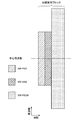
- FIG. 1 is a diagram showing an example of component carrier settings in the present embodiment.
- one LTE cell and two NR cells are set.
- One LTE cell is set as a primary cell.
- the two NR cells are set as a primary secondary cell and a secondary cell, respectively.
- the two NR cells are integrated by carrier aggregation.
- the LTE cell and the NR cell are integrated by dual connectivity. Note that the LTE cell and the NR cell may be integrated by carrier aggregation.
- the NR since the NR can be assisted by the LTE cell that is the primary cell, the NR may not support some functions such as a function for performing stand-alone communication.
- the function for stand-alone communication includes a function necessary for initial connection.
- FIG. 2 is a diagram illustrating an example of component carrier settings in the present embodiment.
- two NR cells are set.
- the two NR cells are set as a primary cell and a secondary cell, respectively, and are integrated by carrier aggregation.
- the support of the LTE cell becomes unnecessary by supporting the function for the NR cell to perform stand-alone communication.
- the two NR cells may be integrated by dual connectivity.
- a radio frame composed of 10 ms (milliseconds) is defined.
- Each radio frame is composed of two half frames.
- the time interval of the half frame is 5 ms.
- Each half frame is composed of five subframes.
- the subframe time interval is 1 ms and is defined by two consecutive slots.
- the slot time interval is 0.5 ms.
- the i-th subframe in the radio frame is composed of a (2 ⁇ i) th slot and a (2 ⁇ i + 1) th slot. That is, 10 subframes are defined in each radio frame.
- ⁇ Frame structure of NR in this embodiment> In each of the NR cells, one or more predetermined parameters are used in a certain predetermined time length (for example, subframe). That is, in the NR cell, the downlink signal and the uplink signal are each generated with one or more predetermined parameters in a predetermined time length.
- the terminal apparatus 2 generates a downlink signal transmitted from the base station apparatus 1 and an uplink signal transmitted to the base station apparatus 1 with one or more predetermined parameters in a predetermined time length.
- the base station apparatus 1 generates a downlink signal to be transmitted to the terminal apparatus 2 and an uplink signal to be transmitted from the terminal apparatus 2 with one or more predetermined parameters for each predetermined time length.
- the predetermined method includes FDM (Frequency Division Multiplexing), TDM (Time Division Multiplexing), CDM (Code Division Multiplexing), and / or SDM (Spatial Division Multiplexing).
- FDM Frequency Division Multiplexing
- TDM Time Division Multiplexing
- CDM Code Division Multiplexing
- SDM Spatial Division Multiplexing
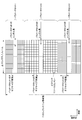
- FIG. 3 is a diagram illustrating an example of an NR downlink subframe in the present embodiment.
- a signal generated using the parameter set 1, the parameter set 0, and the parameter set 2 is FDM in the cell (system bandwidth).
- the diagram shown in FIG. 3 is also referred to as the NR downlink resource grid.
- the base station apparatus 1 can transmit an NR downlink physical channel and / or an NR downlink physical signal in a downlink subframe to the terminal apparatus 2.
- the terminal apparatus 2 can receive the NR downlink physical channel and / or the NR downlink physical signal in the downlink subframe from the base station apparatus 1.
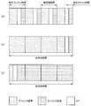
- FIG. 4 is a diagram illustrating an example of an uplink subframe of NR in the present embodiment.
- a signal generated using parameter set 1, parameter set 0, and parameter set 2 is FDM in a cell (system bandwidth).
- the diagram shown in FIG. 3 is also referred to as the NR uplink resource grid.
- the base station apparatus 1 can transmit an NR uplink physical channel and / or an NR uplink physical signal in an uplink subframe to the terminal apparatus 2.
- the terminal apparatus 2 can receive the NR uplink physical channel and / or the NR uplink physical signal in the uplink subframe from the base station apparatus 1.
- physical resources can be defined as follows.
- One slot is defined by a plurality of symbols.
- the physical signal or physical channel transmitted in each of the slots is represented by a resource grid.
- the resource grid may be defined by a plurality of subcarriers in the frequency direction and a plurality of OFDM symbols in the time direction.
- the resource grid may be defined by a plurality of subcarriers in the frequency direction and a plurality of OFDM symbols or SC-FDMA symbols in the time direction.
- the number of subcarriers or resource blocks may be determined depending on the cell bandwidth.
- the number of symbols in one slot may be determined by, for example, a CP (Cyclic Prefix) type.
- Examples of the CP type include a normal CP and an extended CP.
- the number of OFDM symbols or SC-FDMA symbols constituting one slot is seven.
- the extended CP the number of OFDM symbols or SC-FDMA symbols constituting one slot is six.
- Each element in the resource grid is called a resource element.
- the resource element is identified using a subcarrier index (number) and a symbol index (number).
- the OFDM symbol or SC-FDMA symbol is also simply referred to as a symbol.
- the resource block is used for mapping a certain physical channel (such as PDSCH or PUSCH) to a resource element.
- the resource block may include a virtual resource block and a physical resource block, for example.
- a certain physical channel is mapped to a virtual resource block.
- a virtual resource block is mapped to a physical resource block.
- One physical resource block is defined by, for example, a predetermined number of consecutive symbols in the time domain.
- One physical resource block is defined by, for example, a predetermined number of continuous subcarriers in the frequency domain. The number of symbols and the number of subcarriers in one physical resource block are determined based on the type of CP in the cell, the subcarrier spacing, and / or parameters set by higher layers.
- one physical resource block is composed of (7 ⁇ 12) resource elements.
- Physical resource blocks are numbered from 0 in the frequency domain. Further, two resource blocks in one subframe corresponding to the same physical resource block number are defined as physical resource block pairs (PRB pair, RB pair).
- An antenna port is defined so that a propagation channel carrying one symbol can be inferred from a propagation channel carrying another symbol at the same antenna port. For example, it can be assumed that different physical resources in the same antenna port are transmitted on the same propagation channel. In other words, a symbol at a certain antenna port can be demodulated by estimating a propagation channel using a reference signal at that antenna port. There is one resource grid per antenna port.
- An antenna port is defined by a reference signal. Each reference signal can define a plurality of antenna ports.
- An antenna port is identified or identified by an antenna port number. For example, antenna ports 0 to 3 are antenna ports to which CRS is transmitted. That is, the PDSCH transmitted through the antenna ports 0 to 3 can be demodulated by the CRS corresponding to the antenna ports 0 to 3.
- the two antenna ports satisfy a predetermined condition, they can be expressed as quasi-identical positions (QCL: Quasi co-location).
- the predetermined condition is that the wide-area characteristics of a propagation channel carrying a symbol at one antenna port can be inferred from the propagation channel carrying a symbol at another antenna port.
- Global characteristics include delay dispersion, Doppler spread, Doppler shift, average gain and / or average delay.
- the antenna port number may be defined differently for each RAT, or may be defined in common between RATs.
- antenna ports 0 to 3 in LTE are antenna ports through which CRS is transmitted.
- the antenna ports 0 to 3 can be antenna ports through which CRS similar to LTE is transmitted.
- an antenna port for transmitting a CRS similar to LTE can have an antenna port number different from antenna ports 0 to 3.
- the predetermined antenna port number can be applied to LTE and / or NR.
- the PBCH is used to broadcast an MIB (Master Information Block) that is broadcast information unique to the serving cell of the base station apparatus 1.
- MIB Master Information Block
- SFN is a radio frame number (system frame number).
- MIB is system information.
- the MIB includes information indicating SFN.
- PDCCH and EPDCCH are used to transmit downlink control information (DCI). Mapping of information bits of downlink control information is defined as a DCI format.
- the downlink control information includes a downlink grant (downlink grant) and an uplink grant (uplink grant).
- the downlink grant is also referred to as a downlink assignment or a downlink allocation.
- the PDCCH is transmitted by a set of one or more continuous CCEs (Control Channel Elements).
- the CCE is composed of nine REGs (Resource Element Groups).
- the REG is composed of four resource elements.
- EPDCCH is transmitted by a set of one or more continuous ECCEs (Enhanced Control Channel Elements).
- ECCE is composed of multiple EREGs (Enhanced Resource Element Group).
- the downlink grant is used for scheduling the PDSCH in a certain cell.
- the downlink grant is used for scheduling the PDSCH in the same subframe as the subframe in which the downlink grant is transmitted.
- the uplink grant is used for scheduling the PUSCH in a certain cell.
- the uplink grant is used for scheduling a single PUSCH in a subframe that is four or more times after the subframe in which the uplink grant is transmitted.
- the CRC parity bit is added to DCI.
- the CRC parity bit is scrambled by RNTI (Radio Network Temporary Identifier).
- the RNTI is an identifier that can be defined or set according to the purpose of the DCI.
- the RNTI is set as an identifier preliminarily specified in the specification, an identifier set as information specific to a cell, an identifier set as information specific to the terminal device 2, or information specific to a group belonging to the terminal device 2.
- Identifier For example, in monitoring PDCCH or EPDCCH, the terminal device 2 descrambles a CRC parity bit added to DCI with a predetermined RNTI and identifies whether the CRC is correct. If the CRC is correct, it can be seen that the DCI is the DCI for the terminal device 2.
- PDSCH is used to transmit downlink data (Downlink Shared Channel: DL-SCH).
- DL-SCH Downlink Shared Channel
- the PDSCH is also used for transmitting higher layer control information.
- a plurality of PDCCHs may be frequency, time and / or spatially multiplexed.
- a plurality of EPDCCHs may be frequency, time and / or spatially multiplexed.
- a plurality of PDSCHs may be frequency, time and / or spatially multiplexed.
- PDCCH, PDSCH and / or EPDCCH may be frequency, time and / or spatially multiplexed.
- the synchronization signal is used for the terminal apparatus 2 to synchronize the downlink frequency domain and / or time domain.
- the synchronization signal includes PSS (Primary Synchronization Signal) and SSS (Secondary Synchronization Signal).
- the synchronization signal is arranged in a predetermined subframe in the radio frame. For example, in the TDD scheme, the synchronization signal is arranged in subframes 0, 1, 5, and 6 in the radio frame. In the FDD scheme, the synchronization signal is arranged in subframes 0 and 5 in the radio frame.
- PSS may be used for coarse frame / symbol timing synchronization (time domain synchronization) and cell identification group identification.
- the SSS may be used for more accurate frame timing synchronization, cell identification, and CP length detection. That is, frame timing synchronization and cell identification can be performed by using PSS and SSS.
- the terminal apparatus 2 estimates downlink physical channel propagation path, propagation path correction, downlink CSI (Channel State Information) calculation, and / or positioning measurement of the terminal apparatus 2. Used to do
- URS related to PDSCH is transmitted in a subframe and a band used for transmission of PDSCH related to URS. URS is used to demodulate the PDSCH with which the URS is associated. The URS associated with the PDSCH is transmitted on one or more of the antenna ports 5, 7-14.
- the PDSCH is transmitted by an antenna port used for transmission of CRS or URS based on the transmission mode and the DCI format.
- the DCI format 1A is used for scheduling of PDSCH transmitted through an antenna port used for CRS transmission.
- the DCI format 2D is used for scheduling of the PDSCH transmitted through the antenna port used for URS transmission.
- DMRS related to EPDCCH is transmitted in subframes and bands used for transmission of EPDCCH related to DMRS.
- DMRS is used to demodulate the EPDCCH with which DMRS is associated.
- the EPDCCH is transmitted through an antenna port used for DMRS transmission.
- the DMRS associated with the EPDCCH is transmitted on one or more of the antenna ports 107-114.
- CSI-RS is transmitted in the set subframe. Resources for transmitting the CSI-RS are set by the base station apparatus 1.
- the CSI-RS is used for the terminal apparatus 2 to calculate downlink channel state information.
- the terminal device 2 performs signal measurement (channel measurement) using CSI-RS.
- CSI-RS supports configuration of some or all antenna ports of 1, 2, 4, 8, 12, 16, 24 and 32.
- CSI-RS is transmitted on one or more of antenna ports 15-46.
- the supported antenna port may be determined based on the terminal device capability of the terminal device 2, the setting of the RRC parameter, and / or the set transmission mode.
- ZP CSI-RS resources are set by higher layers. ZP CSI-RS resources may be transmitted with zero output power. That is, no ZP CSI-RS resource need be transmitted. PDSCH and EPDCCH are not transmitted in the resource set by ZP CSI-RS.
- ZP CSI-RS resources are used by neighboring cells to transmit NZP CSI-RS.
- ZP CSI-RS resources are used to measure CSI-IM.
- the ZP CSI-RS resource is a resource to which a predetermined channel such as PDSCH is not transmitted. In other words, a predetermined channel is mapped by excluding ZP CSI-RS resources (rate matching and puncturing).
- the PUCCH is a physical channel used for transmitting uplink control information (UPCI).
- the uplink control information includes downlink channel state information (CSI), scheduling request (SR) indicating a request for PUSCH resources, downlink data (Transport block: TB, Downlink-Shared Channel: DL).
- -SCH downlink data for HARQ-ACK.
- HARQ-ACK is also referred to as ACK / NACK, HARQ feedback, or response information.
- HARQ-ACK for downlink data indicates ACK, NACK, or DTX.
- PUSCH is a physical channel used for transmitting uplink data (Uplink-Shared Channel: UL-SCH).
- the PUSCH may also be used to transmit HARQ-ACK and / or channel state information along with uplink data. Also, the PUSCH may be used to transmit only channel state information or only HARQ-ACK and channel state information.
- PRACH is a physical channel used to transmit a random access preamble.
- the PRACH can be used for the terminal device 2 to synchronize with the base station device 1 in the time domain.
- PRACH is an initial connection establishment procedure (processing), a handover procedure, a connection re-establishment procedure, synchronization for uplink transmission (timing adjustment), and / or PUSCH resource request. Also used to indicate
- a plurality of PUCCHs are frequency, time, space and / or code multiplexed.
- a plurality of PUSCHs may be frequency, time, space and / or code multiplexed.
- PUCCH and PUSCH may be frequency, time, space and / or code multiplexed.
- the PRACH may be arranged over a single subframe or two subframes. A plurality of PRACHs may be code-multiplexed.
- UL-DMRS is related to transmission of PUSCH or PUCCH.
- UL-DMRS is time-multiplexed with PUSCH or PUCCH.
- the base station apparatus 1 may use UL-DMRS to perform PUSCH or PUCCH propagation path correction.
- PUSCH transmission also includes multiplexing and transmitting PUSCH and UL-DMRS.
- the transmission of PUCCH includes multiplexing and transmitting PUCCH and UL-DMRS.
- SRS is not related to PUSCH or PUCCH transmission.
- the base station apparatus 1 may use SRS in order to measure the uplink channel state.
- SRS is transmitted using the last symbol in the uplink subframe. That is, the SRS is arranged in the last symbol in the uplink subframe.
- the terminal device 2 can restrict simultaneous transmission of SRS and PUCCH, PUSCH and / or PRACH in a certain symbol of a certain cell.
- the terminal apparatus 2 transmits PUSCH and / or PUCCH using a symbol excluding the last symbol in the uplink subframe in an uplink subframe of a certain cell, and the last symbol in the uplink subframe. Can be used to transmit SRS. That is, in a certain uplink subframe of a certain cell, the terminal device 2 can transmit SRS, PUSCH and PUCCH.
- trigger type 0 SRS and trigger type 1 SRS are defined as SRSs having different trigger types.
- the trigger type 0 SRS is transmitted when parameters related to the trigger type 0 SRS are set by higher layer signaling.
- the trigger type 1 SRS is transmitted when a parameter related to the trigger type 1 SRS is set by higher layer signaling and transmission is requested by an SRS request included in the DCI format 0, 1A, 2B, 2C, 2D, or 4.
- the SRS request is included in both FDD and TDD for DCI formats 0, 1A, and 4, and is included only in TDD for DCI formats 2B, 2C, and 2D.
- Trigger type 0 SRS is also referred to as periodic SRS.
- Trigger type 1 SRS is also referred to as aperiodic SRS.
- FIG. 5 is a schematic block diagram showing the configuration of the base station apparatus 1 of the present embodiment.
- the base station apparatus 1 includes an upper layer processing unit 101, a control unit 103, a receiving unit 105, a transmitting unit 107, and a transmission / reception antenna 109.
- the reception unit 105 includes a decoding unit 1051, a demodulation unit 1053, a demultiplexing unit 1055, a radio reception unit 1057, and a channel measurement unit 1059.
- the transmission unit 107 includes an encoding unit 1071, a modulation unit 1073, a multiplexing unit 1075, a radio transmission unit 1077, and a downlink reference signal generation unit 1079.
- the base station apparatus 1 can support one or more RATs. Some or all of the units included in the base station apparatus 1 shown in FIG. 5 can be individually configured according to the RAT. For example, the reception unit 105 and the transmission unit 107 are individually configured with LTE and NR. Further, in the NR cell, a part or all of each unit included in the base station apparatus 1 shown in FIG. 5 can be individually configured according to a parameter set related to a transmission signal. For example, in a certain NR cell, the radio reception unit 1057 and the radio transmission unit 1077 can be individually configured according to a parameter set regarding a transmission signal.
- the upper layer processing unit 101 includes a medium access control (MAC) layer, a packet data integration protocol (Packet Data Convergence Protocol: PDCP) layer, a radio link control (Radio Link Control: RLC) layer, a radio resource control (Radio). Process Resource Control: RRC) layer. Further, the upper layer processing unit 101 generates control information for controlling the reception unit 105 and the transmission unit 107 and outputs the control information to the control unit 103.
- MAC medium access control
- PDCP Packet Data Convergence Protocol
- RLC Radio Link Control
- Radio Radio
- RRC Radio Resource Control
- the control unit 103 controls the reception unit 105 and the transmission unit 107 based on the control information from the higher layer processing unit 101.
- the control unit 103 generates control information for the upper layer processing unit 101 and outputs the control information to the upper layer processing unit 101.
- the control unit 103 inputs the decoded signal from the decoding unit 1051 and the channel estimation result from the channel measurement unit 1059.
- the control unit 103 outputs a signal to be encoded to the encoding unit 1071.
- the control unit 103 is used to control all or part of the base station apparatus 1.
- the upper layer processing unit 101 performs processing and management related to RAT control, radio resource control, subframe setting, scheduling control, and / or CSI report control.
- the processing and management in the upper layer processing unit 101 is performed for each terminal device or for the terminal devices connected to the base station device.
- the processing and management in the upper layer processing unit 101 may be performed only by the upper layer processing unit 101, or may be acquired from an upper node or another base station device. Further, the processing and management in the upper layer processing unit 101 may be performed individually according to the RAT. For example, the upper layer processing unit 101 individually performs processing and management in LTE and processing and management in NR.
- management related to RAT is performed.
- management related to LTE and / or management related to NR is performed.
- Management regarding NR includes setting and processing of parameter sets regarding transmission signals in the NR cell.
- radio resource control in the upper layer processing unit 101, generation and / or management of downlink data (transport block), system information, RRC message (RRC parameter), and / or MAC control element (CE) is performed. Done.
- subframe setting in the upper layer processing unit 101 subframe setting, subframe pattern setting, uplink-downlink setting, uplink reference UL-DL setting, and / or downlink reference UL-DL setting are managed. Is called.
- the subframe setting in higher layer processing section 101 is also referred to as base station subframe setting.
- the subframe setting in the higher layer processing unit 101 can be determined based on the uplink traffic volume and the downlink traffic volume. Further, the subframe setting in the upper layer processing unit 101 can be determined based on the scheduling result of the scheduling control in the upper layer processing unit 101.
- the frequency and subframe to which a physical channel is allocated, the physical channel's A coding rate, a modulation scheme, transmission power, and the like are determined.
- the control unit 103 generates control information (DCI format) based on the scheduling result of scheduling control in the upper layer processing unit 101.
- the CSI report of the terminal device 2 is controlled.
- the setting related to the CSI reference resource to be assumed for calculating the CSI in the terminal device 2 is controlled.
- the receiving unit 105 receives a signal transmitted from the terminal device 2 via the transmission / reception antenna 109 in accordance with control from the control unit 103, further performs reception processing such as separation, demodulation, and decoding, and receives the received information. Output to the control unit 103. Note that the reception process in the reception unit 105 is performed based on a setting specified in advance or a setting notified from the base station apparatus 1 to the terminal apparatus 2.
- the radio reception unit 1057 converts the uplink signal received via the transmission / reception antenna 109 into an intermediate frequency (down-conversion), removes unnecessary frequency components, and appropriately maintains the signal level. Control of amplification level, quadrature demodulation based on in-phase and quadrature components of received signal, conversion from analog signal to digital signal, removal of guard interval (Guard Interval: GI), and / or fast Fourier transform (Fast Fourier Transform) Extract frequency domain signals by Transform: FFT).
- GI Guard Interval
- FFT Fast Fourier transform
- the demultiplexing unit 1055 separates an uplink channel such as PUCCH or PUSCH and / or an uplink reference signal from the signal input from the radio reception unit 1057.
- the demultiplexing unit 1055 outputs the uplink reference signal to the channel measurement unit 1059.
- the demultiplexing unit 1055 performs channel compensation for the uplink channel from the channel estimation value input from the channel measurement unit 1059.
- the demodulation unit 1053 receives a received signal using a modulation scheme such as BPSK (Binary Phase Shift Keying), QPSK (Quadrature Phase Shift Keying), 16QAM (Quadrature Amplitude Modulation), 64QAM, or 256QAM for the modulation symbol of the uplink channel. Is demodulated.
- Demodulation section 1053 separates and demodulates the MIMO multiplexed uplink channel.
- the decoding unit 1051 performs a decoding process on the demodulated uplink channel encoded bits.
- the decoded uplink data and / or uplink control information is output to the control unit 103.
- Decoding section 1051 performs decoding processing for each transport block for PUSCH.
- the channel measurement unit 1059 measures the propagation path estimation value and / or channel quality from the uplink reference signal input from the demultiplexing unit 1055, and outputs it to the demultiplexing unit 1055 and / or the control unit 103.
- the channel measurement unit 1059 measures a channel estimation value for channel compensation for PUCCH or PUSCH using UL-DMRS, and measures the channel quality in the uplink using SRS.
- the transmission unit 107 performs transmission processing such as encoding, modulation, and multiplexing on the downlink control information and the downlink data input from the higher layer processing unit 101 according to the control from the control unit 103. For example, the transmission unit 107 generates and multiplexes PHICH, PDCCH, EPDCCH, PDSCH, and a downlink reference signal, and generates a transmission signal. Note that the transmission processing in the transmission unit 107 is based on settings specified in advance, settings notified from the base station apparatus 1 to the terminal apparatus 2, or settings notified via the PDCCH or EPDCCH transmitted in the same subframe. Done.
- the encoding unit 1071 performs HARQ indicator (HARQ-ACK), downlink control information, and downlink data input from the control unit 103 with predetermined encoding such as block encoding, convolutional encoding, and turbo encoding. Encoding is performed using a method.
- the modulation unit 1073 modulates the coded bits input from the coding unit 1071 with a predetermined modulation method such as BPSK, QPSK, 16QAM, 64QAM, 256QAM.
- the downlink reference signal generation unit 1079 generates a downlink reference signal based on a physical cell identifier (PCI), an RRC parameter set in the terminal device 2, and the like.
- Multiplexer 1075 multiplexes the modulation symbols and downlink reference signals for each channel and arranges them in a predetermined resource element.
- the radio transmission unit 1077 converts the signal from the multiplexing unit 1075 into a signal in the time domain by inverse fast Fourier transform (IFFT), adds a guard interval, generates a baseband digital signal, Performs conversion to analog signal, quadrature modulation, conversion from intermediate frequency signal to high frequency signal (up-convert), removal of excess frequency components, power amplification, etc. to generate a transmission signal .
- IFFT inverse fast Fourier transform
- up-convert up-convert
- removal of excess frequency components power amplification, etc.
- FIG. 6 is a schematic block diagram showing the configuration of the terminal device 2 of the present embodiment.
- the terminal device 2 includes an upper layer processing unit 201, a control unit 203, a reception unit 205, a transmission unit 207, and a transmission / reception antenna 209.
- the reception unit 205 includes a decoding unit 2051, a demodulation unit 2053, a demultiplexing unit 2055, a radio reception unit 2057, and a channel measurement unit 2059.
- the transmission unit 207 includes an encoding unit 2071, a modulation unit 2073, a multiplexing unit 2075, a radio transmission unit 2077, and an uplink reference signal generation unit 2079.
- the terminal device 2 can support one or more RATs. Part or all of the units included in the terminal device 2 illustrated in FIG. 6 can be individually configured according to the RAT.
- the reception unit 205 and the transmission unit 207 are individually configured with LTE and NR.
- some or all of the units included in the terminal apparatus 2 shown in FIG. 6 can be individually configured according to the parameter set related to the transmission signal.
- the radio reception unit 2057 and the radio transmission unit 2077 can be individually configured according to a parameter set related to a transmission signal.
- the higher layer processing unit 201 outputs the uplink data (transport block) to the control unit 203.
- the upper layer processing unit 201 includes a medium access control (MAC) layer, a packet data integration protocol (Packet Data Convergence Protocol: PDCP) layer, a radio link control (Radio Link Control: RLC) layer, a radio resource control (Radio). Process Resource Control: RRC) layer. Further, the upper layer processing unit 201 generates control information for controlling the reception unit 205 and the transmission unit 207 and outputs the control information to the control unit 203.
- MAC medium access control
- PDCP Packet Data Convergence Protocol
- RLC Radio Link Control
- RRC Radio Resource Control
- the control unit 203 controls the reception unit 205 and the transmission unit 207 based on the control information from the higher layer processing unit 201.
- the control unit 203 generates control information for the upper layer processing unit 201 and outputs the control information to the upper layer processing unit 201.
- the control unit 203 inputs the decoded signal from the decoding unit 2051 and the channel estimation result from the channel measurement unit 2059.
- the control unit 203 outputs a signal to be encoded to the encoding unit 2071. Further, the control unit 203 may be used to control all or part of the terminal device 2.
- the upper layer processing unit 201 performs processing and management related to RAT control, radio resource control, subframe setting, scheduling control, and / or CSI report control.
- the processing and management in the upper layer processing unit 201 are performed based on settings specified in advance and / or settings based on control information set or notified from the base station apparatus 1.
- the control information from the base station apparatus 1 includes an RRC parameter, a MAC control element, or DCI.
- the processing and management in the upper layer processing unit 201 may be performed individually according to the RAT.
- the upper layer processing unit 201 individually performs processing and management in LTE and processing and management in NR.
- management related to RAT is performed.
- management related to LTE and / or management related to NR is performed.
- Management regarding NR includes setting and processing of parameter sets regarding transmission signals in the NR cell.
- radio resource control in the higher layer processing unit 201 management of setting information in the own apparatus is performed.
- radio resource control in the upper layer processing unit 201 generation and / or management of uplink data (transport block), system information, RRC message (RRC parameter), and / or MAC control element (CE) is performed. Done.
- the subframe setting in the upper layer processing unit 201 the subframe setting in the base station apparatus 1 and / or a base station apparatus different from the base station apparatus 1 is managed.
- the subframe configuration includes uplink or downlink configuration, subframe pattern configuration, uplink-downlink configuration, uplink reference UL-DL configuration, and / or downlink reference UL-DL configuration for the subframe.
- the subframe setting in the higher layer processing unit 201 is also referred to as terminal subframe setting.
- control information for performing control related to scheduling for the reception unit 205 and the transmission unit 207 is generated based on DCI (scheduling information) from the base station apparatus 1.
- control related to CSI reporting to the base station apparatus 1 is performed.
- the channel measurement unit 2059 controls settings related to CSI reference resources that are assumed to calculate CSI.
- resources (timing) used for reporting CSI are controlled based on DCI and / or RRC parameters.
- the receiving unit 205 receives the signal transmitted from the base station apparatus 1 via the transmission / reception antenna 209 according to the control from the control unit 203, and further performs reception processing such as separation, demodulation, decoding, and the like. Is output to the control unit 203. Note that the reception process in the reception unit 205 is performed based on a predetermined setting or a notification or setting from the base station apparatus 1.
- the radio reception unit 2057 converts the uplink signal received via the transmission / reception antenna 209 to an intermediate frequency (down-conversion), removes unnecessary frequency components, and appropriately maintains the signal level. Control of amplification level, quadrature demodulation based on in-phase and quadrature components of received signal, conversion from analog signal to digital signal, removal of guard interval (Guard Interval: GI), and / or fast Fourier transform (Fast Fourier Transform) Extracts frequency domain signals using Transform (FFT).
- FFT Fast Fourier transform
- the demultiplexing unit 2055 separates a downlink channel such as PHICH, PDCCH, EPDCCH, or PDSCH, a downlink synchronization signal, and / or a downlink reference signal from the signal input from the radio reception unit 2057.
- the demultiplexing unit 2055 outputs the downlink reference signal to the channel measurement unit 2059.
- the demultiplexing unit 2055 performs channel compensation for the downlink channel from the channel estimation value input from the channel measurement unit 2059.
- the demodulator 2053 demodulates the received signal using a modulation scheme such as BPSK, QPSK, 16QAM, 64QAM, 256QAM, etc., with respect to the downlink channel modulation symbols.
- the demodulator 2053 separates and demodulates the MIMO multiplexed downlink channel.
- the decoding unit 2051 performs a decoding process on the demodulated downlink channel encoded bits.
- the decoded downlink data and / or downlink control information is output to the control unit 203.
- the decoding unit 2051 performs a decoding process for each transport block on the PDSCH.
- the channel measurement unit 2059 measures the estimated value of the propagation path and / or the channel quality from the downlink reference signal input from the demultiplexing unit 2055 and outputs it to the demultiplexing unit 2055 and / or the control unit 203.
- the downlink reference signal used for measurement by the channel measurement unit 2059 may be determined based on at least the transmission mode set by the RRC parameter and / or other RRC parameters.
- DL-DMRS measures an estimated value of a propagation path for performing propagation path compensation for PDSCH or EPDCCH.
- CRS measures a channel estimation value for performing channel compensation for PDCCH or PDSCH and / or a channel in the downlink for reporting CSI.
- CSI-RS measures the channel in the downlink for reporting CSI.
- the channel measurement unit 2059 calculates RSRP (Reference Signal Received Power) and / or RSRQ (Reference Signal Received Quality) based on the CRS, CSI-RS, or detection signal, and outputs it to the upper layer processing unit
- the transmission unit 207 performs transmission processing such as encoding, modulation, and multiplexing on the uplink control information and the uplink data input from the higher layer processing unit 201 according to the control from the control unit 203. For example, the transmission unit 207 generates and multiplexes an uplink channel such as PUSCH or PUCCH and / or an uplink reference signal, and generates a transmission signal. Note that the transmission processing in the transmission unit 207 is performed based on settings specified in advance or settings or notifications from the base station apparatus 1.
- the encoding unit 2071 encodes the HARQ indicator (HARQ-ACK), the uplink control information, and the uplink data input from the control unit 203 with predetermined encoding such as block encoding, convolutional encoding, and turbo encoding. Encoding is performed using a method.
- the modulation unit 2073 modulates the coded bits input from the coding unit 2071 using a predetermined modulation method such as BPSK, QPSK, 16QAM, 64QAM, or 256QAM.
- the uplink reference signal generation unit 2079 generates an uplink reference signal based on the RRC parameter set in the terminal device 2 and the like.
- Multiplexing section 2075 multiplexes the modulation symbols and uplink reference signals for each channel and arranges them in a predetermined resource element.
- the radio transmission unit 2077 converts the signal from the multiplexing unit 2075 into a time domain signal by Inverse Fast Fourier Transform (IFFT), adds a guard interval, generates a baseband digital signal, Performs conversion to analog signal, quadrature modulation, conversion from intermediate frequency signal to high frequency signal (up-convert), removal of excess frequency components, power amplification, etc. to generate a transmission signal .
- IFFT Inverse Fast Fourier Transform
- the transmission signal output from the wireless transmission unit 2077 is transmitted from the transmission / reception antenna 209.
- the base station apparatus 1 and the terminal apparatus 2 can use various methods for control information signaling (notification, notification, and setting), respectively.
- Signaling of control information can be performed in various layers.
- the signaling of control information includes physical layer signaling that is signaling through the physical layer (layer), RRC signaling that is signaling through the RRC layer, and MAC signaling that is signaling through the MAC layer.
- the RRC signaling is dedicated RRC signaling (Dedicated RRC signaling) for notifying control information unique to the terminal device 2 or common RRC signaling (Common RRC signaling) for notifying control information unique to the base station device 1.
- Signaling used by higher layers as viewed from the physical layer, such as RRC signaling and MAC signaling is also referred to as upper layer signaling.
- RRC signaling is realized by signaling RRC parameters.
- MAC signaling is realized by signaling a MAC control element.
- Physical layer signaling is realized by signaling downlink control information (DCI: Downlink Control Information) or uplink control information (UCI: Uplink Control Information).
- DCI Downlink Control Information
- UCI Uplink Control Information
- the RRC parameter and the MAC control element are transmitted using PDSCH or PUSCH.
- DCI is transmitted using PDCCH or EPDCCH.
- UCI is transmitted using PUCCH or PUSCH.
- RRC signaling and MAC signaling are used for signaling semi-static control information and are also referred to as semi-static signaling.
- Physical layer signaling is used to signal dynamic control information and is also referred to as dynamic signaling.
- DCI is used for PDSCH scheduling or PUSCH scheduling.
- the UCI is used for CSI reporting, HARQ-ACK reporting, and / or scheduling request (SR).
- SR scheduling request
- the DCI is notified using a DCI format having a predefined field.
- predetermined information bits are mapped.
- DCI notifies downlink scheduling information, uplink scheduling information, side link scheduling information, aperiodic CSI report request, or uplink transmission power command.
- the DCI format monitored by the terminal device 2 is determined by the transmission mode set for each serving cell. That is, a part of the DCI format monitored by the terminal device 2 can be different depending on the transmission mode.
- the terminal device 2 in which the downlink transmission mode 1 is set monitors the DCI format 1A and the DCI format 1.
- the terminal device 2 in which the downlink transmission mode 4 is set monitors the DCI format 1A and the DCI format 2.
- the terminal device 2 in which the uplink transmission mode 1 is set monitors the DCI format 0.
- the terminal device 2 in which the uplink transmission mode 2 is set monitors the DCI format 0 and the DCI format 4.
- the control region in which the PDCCH that notifies the DCI for the terminal device 2 is not notified, and the terminal device 2 detects the DCI for the terminal device 2 by blind decoding (blind detection). Specifically, the terminal device 2 monitors a set of PDCCH candidates in the serving cell. Monitoring means attempting to decode with all monitored DCI formats for each of the PDCCHs in the set. For example, the terminal device 2 tries to decode all the aggregation levels, PDCCH candidates, and DCI formats that may be transmitted to the terminal device 2. The terminal device 2 recognizes the DCI (PDCCH) that has been successfully decoded (detected) as the DCI (PDCCH) for the terminal device 2.
- PDCCH DCI
- Cyclic Redundancy Check is added to DCI.
- the CRC is used for DCI error detection and DCI blind detection.
- CRC CRC parity bit
- RNTI Radio Network Temporary Identifier
- the terminal device 2 detects whether it is DCI for the terminal device 2 based on the RNTI. Specifically, the terminal device 2 descrambles the bit corresponding to the CRC with a predetermined RNTI, extracts the CRC, and detects whether the corresponding DCI is correct.
- RNTI is specified or set according to the purpose and application of DCI.
- RNTI is C-RNTI (Cell-RNTI), SPS C-RNTI (Semi Persistent Scheduling C-RNTI), SI-RNTI (System Information-RNTI), P-RNTI (Paging-RNTI), RA-RNTI (Random Access) -RNTI), TPC-PUCCH-RNTI (Transmit Power Control-PUCCH-RNTI), TPC-PUSCH-RNTI (Transmit Power Control-PUSCH-RNTI), Temporary C-RNTI, M-RNTI (MBMS (Multimedia Broadcast Multicast Services) ) -RNTI), eIMTA-RNTI, CC-RNTI.
- C-RNTI Cell-RNTI
- SPS C-RNTI Semi Persistent Scheduling C-RNTI
- SI-RNTI System Information-RNTI
- P-RNTI Paging-RNTI
- RA-RNTI Random Access
- C-RNTI and SPS C-RNTI are RNTIs specific to the terminal device 2 in the base station device 1 (cell), and are identifiers for identifying the terminal device 2.
- C-RNTI is used to schedule PDSCH or PUSCH in a certain subframe.
- the SPS C-RNTI is used to activate or release periodic scheduling of resources for PDSCH or PUSCH.
- a control channel having a CRC scrambled by SI-RNTI is used for scheduling an SIB (System Information Block).
- SIB System Information Block
- a control channel with a CRC scrambled with P-RNTI is used to control paging.
- a control channel having a CRC scrambled with RA-RNTI is used to schedule a response to RACH.
- a control channel having a CRC scrambled by TPC-PUCCH-RNTI is used for power control of PUCCH.
- a control channel having a CRC scrambled by TPC-PUSCH-RNTI is used to perform power control of PUSCH.
- a control channel having a CRC scrambled with Temporary C-RNTI is used by a mobile station apparatus for which C-RNTI is not set or recognized.
- a control channel with CRC scrambled with M-RNTI is used to schedule MBMS.
- a control channel having a CRC scrambled by eIMTA-RNTI is used for notifying information on TDD UL / DL configuration of a TDD serving cell in dynamic TDD (eIMTA).
- a control channel (DCI) having a CRC scrambled with CC-RNTI is used in the LAA secondary cell to notify the setting of a dedicated OFDM symbol.
- DCI control channel
- the DCI format may be scrambled not only by the above RNTI but also by a new RNTI.
- Scheduling information includes information for performing scheduling in units of resource blocks or resource block groups as frequency domain scheduling.
- the resource block group is a set of consecutive resource blocks, and indicates resources allocated to terminal devices to be scheduled.
- the size of the resource block group is determined according to the system bandwidth.
- DCI is transmitted using a control channel such as PDCCH or EPDCCH.
- the terminal device 2 monitors a set of PDCCH candidates and / or a set of EPDCCH candidates of one or more activated serving cells configured by RRC signaling.
- monitoring means trying to decode PDCCH and / or EPDCCH in a set corresponding to all monitored DCI formats.
- the PDCCH candidate set or EPDCCH candidate set is also called a search space.
- a search space a shared search space (CSS) and a terminal-specific search space (USS) are defined.
- the CSS may be defined only for the search space for PDCCH.
- CSS Common Search Space
- the USS UE-specific Search Space
- USS is a search space set using at least parameters specific to the terminal device 2. Therefore, USS is a search space unique to the terminal device 2, and the base station device 1 can individually transmit a control channel unique to the terminal device 2 by the USS. Therefore, the base station apparatus 1 can efficiently map control channels unique to a plurality of terminal apparatuses.
- USS may be set so as to be used in common by a plurality of terminal devices. Since a common USS is set for a plurality of terminal devices, parameters unique to the terminal device 2 are set so as to have the same value among the plurality of terminal devices. For example, a unit set to the same parameter among a plurality of terminal devices is a cell, a transmission point, a group of predetermined terminal devices, or the like.
- the search space for each aggregation level is defined by a set of PDCCH candidates.
- Each PDCCH is transmitted using a set of one or more CCEs (Control Channel Elements).
- the number of CCEs used for one PDCCH is also referred to as an aggregation level. For example, the number of CCEs used for one PDCCH is 1, 2, 4 or 8.
- the number of PDCCH candidates is determined based on at least the search space and the aggregation level. For example, in CSS, the number of PDCCH candidates at aggregation levels 4 and 8 is 4 and 2, respectively. For example, in USS, the numbers of PDCCH candidates in aggregations 1, 2, 4, and 8 are 6, 6, 2, and 2, respectively.
- the base station device 1 can use a plurality of methods as a method of assigning PDSCH and / or PUSCH resources to the terminal device 2.
- Resource allocation methods include dynamic scheduling, semi-persistent scheduling, multi-subframe scheduling, and cross-subframe scheduling.
- one DCI performs resource allocation in one subframe. Specifically, PDCCH or EPDCCH in a certain subframe performs scheduling for PDSCH in that subframe. PDCCH or EPDCCH in a certain subframe performs scheduling for PUSCH in a predetermined subframe after that subframe.
- one DCI performs resource allocation in one or more subframes.
- PDCCH or EPDCCH in a certain subframe performs scheduling for PDSCH in one or more subframes after a predetermined number of subframes.
- PDCCH or EPDCCH in a certain subframe performs scheduling for PUSCH in one or more subframes after a predetermined number of times from the subframe.
- the predetermined number can be an integer greater than or equal to zero.
- the predetermined number may be defined in advance or may be determined based on physical layer signaling and / or RRC signaling.
- consecutive subframes may be scheduled, or subframes having a predetermined period may be scheduled.
- the number of subframes to be scheduled may be predetermined or may be determined based on physical layer signaling and / or RRC signaling.
- one DCI performs resource allocation in one subframe.
- PDCCH or EPDCCH in a certain subframe performs scheduling for PDSCH in one subframe that is a predetermined number after that subframe.
- PDCCH or EPDCCH in a certain subframe performs scheduling for PUSCH in one subframe after a predetermined number of times from the subframe.
- the predetermined number can be an integer greater than or equal to zero.
- the predetermined number may be defined in advance or may be determined based on physical layer signaling and / or RRC signaling.
- continuous subframes may be scheduled, or subframes having a predetermined period may be scheduled.
- one DCI performs resource allocation in one or more subframes.
- the terminal device 2 sets information related to SPS by RRC signaling and detects PDCCH or EPDCCH for enabling SPS, the terminal device 2 enables processing related to SPS, and performs predetermined PDSCH and / or PUSCH based on the setting related to SPS.
- the terminal apparatus 2 detects PDCCH or EPDCCH for releasing SPS when SPS is valid, the terminal apparatus 2 releases (invalidates) SPS and stops receiving predetermined PDSCH and / or PUSCH.
- the release of the SPS may be performed based on a case where a predetermined condition is satisfied. For example, the SPS is released when a predetermined number of empty transmission data is received. Empty transmission of data for releasing SPS corresponds to MAC PDU (Protocol Data Unit) including zero MAC SDU (Service Data Unit).
- MAC PDU Protocol Data Unit
- MAC SDU Service Data Unit
- Information related to SPS by RRC signaling includes SPS C-RNTI, which is the RNTI of SPS, information related to PDSCH scheduled period (interval), information related to PUSCH scheduled period (interval), and settings for releasing SPS.
- SPS C-RNTI is the RNTI of SPS
- information related to PDSCH scheduled period (interval) information related to PUSCH scheduled period (interval)
- settings for releasing SPS information related to SPS by RRC signaling.
- SPS is supported only for primary cells and / or primary secondary cells.
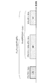
- FIG. 15 shows an example of a frame configuration of self-contained transmission in this embodiment.
- one transmission / reception is configured in the order of downlink transmission, GP, and continuous downlink transmission from the top.
- the continuous downlink transmission includes at least one downlink control information and DMRS.
- the downlink control information instructs reception of a downlink physical channel included in the continuous downlink transmission or transmission of an uplink physical channel included in the continuous uplink transmission.
- the terminal device 2 tries to receive the downlink physical channel based on the downlink control information.
- the terminal device 2 transmits the reception success or failure (decoding success or failure) of the downlink physical channel through the uplink control channel included in the uplink transmission allocated after the GP.
- the downlink control information instructs the transmission of the uplink physical channel
- the uplink physical channel transmitted based on the downlink control information is included in the uplink transmission for transmission.
- downlink low-delay communication can be realized by notifying the success or failure of downlink reception by uplink transmission immediately after.
- the unit slot time is the minimum time unit that defines downlink transmission, GP, or uplink transmission. Unit slot time is reserved for either downlink transmission, GP, or uplink transmission. The unit slot time does not include both downlink transmission and uplink transmission.
- the unit slot time may be the minimum transmission time of a channel associated with the DMRS included in the unit slot time.
- One unit slot time is defined by, for example, an NR sampling interval (T s ) or an integer multiple of a symbol length.
- the unit frame time may be a minimum time specified by scheduling.
- the unit frame time may be a minimum unit in which a transport block is transmitted.
- the unit slot time may be the maximum transmission time of a channel associated with the DMRS included in the unit slot time.
- the unit frame time may be a unit time for determining the uplink transmission power in the terminal device 2.
- the unit frame time may be referred to as a subframe.
- One unit frame time is defined by, for example, an NR sampling interval (T s ), a symbol length, or an integer multiple of a unit slot time.
- the transmission / reception time is one transmission / reception time. Between one transmission / reception and another transmission / reception, time (gap) in which no physical channel and physical signal are transmitted is occupied. The terminal device 2 may not average the CSI measurement between different transmissions and receptions.
- the transmission / reception time may be referred to as TTI.
- One transmission / reception time is defined by, for example, an NR sampling interval (T s ), a symbol length, a unit slot time, or an integer multiple of a unit frame time.
- Uplink RS of NR in this embodiment examples include NR-SRS.
- An example of NR-SRS is described below. Note that features not specified below can be regarded as the same as SRS in LTE.
- NR-SRS may not be transmitted in the last symbol in a subframe or slot.
- the NR-SRS may be transmitted using the first symbol or a middle symbol in a subframe or slot.
- the NR-SRS may be transmitted continuously with a plurality of symbols.
- the NR-SRS may be transmitted in the last few symbols in a subframe or slot.
- NR antenna configuration in this embodiment As the NR antenna, a digital antenna configuration, an analog antenna configuration, and a hybrid antenna configuration in which the digital antenna configuration and the analog antenna configuration are combined are assumed.
- the digital antenna configuration is a configuration in which the antenna weight is controlled by a digital circuit (baseband region) for each antenna element.
- FIG. 8 is a schematic block diagram illustrating an example of a digital antenna configuration according to the present embodiment.
- the configuration of base station apparatus 1 in FIG. 5 is illustrated focusing on the configurations of multiplexing section 1075, radio transmission section 1077, and antenna section 109. Further, in FIG. 8, illustrations of components unnecessary for the description of the basic configuration are omitted, but it is assumed that the components described in FIG. 5 are provided in each unit.
- the multiplexing unit 1075 includes a precoding unit. That is, in the digital antenna configuration, the precoding unit multiplies the transmission signal corresponding to each antenna element by the antenna weight to form a beam.
- the digital antenna configuration it is possible to perform flexible phase control for each antenna element, and it is possible to generate different beams in the frequency domain.
- the digital antenna configuration tends to be complicated.
- FIG. 9 is a schematic block diagram showing an example of an analog antenna configuration in the present embodiment.
- FIG. 9 similarly to FIG. 8, attention is paid to the configuration of the multiplexing unit 1075, the wireless transmission unit 1077, and the antenna unit 109 in the configuration of the base station apparatus 1 of FIG. 5.
- FIG. 9 illustrations of components that are not necessary for the description of the basic configuration are omitted, but it is assumed that the components described in FIG. 5 are provided in each unit.
- the wireless transmission unit 1077 includes a phase control unit.
- a beam is formed by rotating the phase of the transmission signal in the analog region (RF region).
- ⁇ Flexible beam control is complicated in processing to control the phase in the analog domain, but the configuration tends to be simple.
- the antenna switching configuration is part of an analog antenna configuration.
- the hybrid antenna configuration is a combination of a digital antenna configuration and an analog antenna configuration, and has both a phase control element in the analog domain and a phase control element in the digital domain.
- the hybrid antenna configuration has characteristics that are intermediate between the digital antenna configuration and the analog antenna configuration in terms of beamforming performance and configuration complexity.
- ⁇ NR beam operation method in this embodiment In NR, two types of schemes are assumed, single beam operation and multiple beam operation.
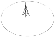
- FIG. 10 is an explanatory diagram for explaining an outline of an example of single beam operation.
- Single beam operation is a scheme in which a predetermined cell coverage is covered by one beam (that is, operated by one beam). Specifically, within a predetermined cell coverage, a cell-specific physical channel or physical signal is transmitted by one beam.
- LTE can be considered single beam operation.
- FIG. 11 is an explanatory diagram for explaining an outline of an example of the multiple beam operation.
- the multiple beam operation is a method in which a predetermined cell coverage is covered by one or more beams (that is, operated by one or more beams). Specifically, a cell-specific physical channel or physical signal is transmitted by a plurality of beams. For example, in analog beam forming and hybrid beam forming, a beam in a predetermined direction is transmitted in a predetermined time instance, and it is difficult to transmit in a beam other than the beam in the predetermined direction. Therefore, for example, by switching time instances, beams in a plurality of directions are switched, and a wide area can be covered.
- a predetermined beam in which a cell-specific physical channel or physical signal is transmitted is transmitted in one time instance (time resource). Also, different beams are transmitted at different time instances.
- a plurality of beams are switched and operated in a plurality of time instances. Switching between multiple beams at multiple time instances is referred to as beam sweep.
- a beam can be restated in terms such as a channel, a path, an antenna, and an antenna port. That is, transmission using different beams can be said to be transmission using different channels, paths, antennas, or antenna ports. Furthermore, the beam can be assumed as a virtual cell. The terminal device can recognize different beams transmitted from the same cell as different virtual cells or virtual carriers.
- information that can be paraphrased as a beam such as the channel, path, antenna, and antenna port, information related to control of the beam (for example, information related to antenna settings, etc.), etc. Also referred to as “antenna information”. That is, a signal transmitted by a predetermined beam can be regarded as being associated with antenna information corresponding to the beam.
- the system preferably selects an appropriate beam for each downlink and uplink. Specifically, it is preferable that an appropriate beam is selected for each of the downlink transmission beam of the base station apparatus and the downlink reception beam of the terminal apparatus. Moreover, it is preferable that an appropriate beam is selected for each of the uplink transmission beam of the terminal apparatus and the uplink reception beam of the base station apparatus.
- the base station apparatus can recognize an appropriate downlink transmission beam based on a report or feedback information from a terminal apparatus that receives a signal transmitted from the base station apparatus.
- the base station apparatus transmits a predetermined known signal a plurality of times using different downlink transmission beams.
- the terminal apparatus determines an appropriate downlink transmission beam from each of the known signals transmitted a plurality of times by different downlink transmission beams based on reception strength or reception quality, and sets the appropriate downlink transmission beam. Corresponding information is reported or fed back to the base station apparatus. Thereby, the base station apparatus can recognize an appropriate downlink transmission beam.
- the known signal include various reference signals such as NR-SS, MRS, BRS, NR-CSI-RS, and NR-DM-RS.
- the base station apparatus can recognize an appropriate downlink transmission beam based on an appropriate uplink reception beam of the base station apparatus.
- the terminal apparatus can recognize an appropriate uplink transmission beam based on a report or feedback information from a base station apparatus that receives a signal transmitted from the terminal apparatus.
- a process in which the terminal apparatus recognizes an appropriate uplink transmission beam is shown.
- the terminal apparatus transmits a predetermined known signal a plurality of times using different uplink transmission beams.
- the base station apparatus determines an appropriate uplink transmission beam from each of the known signals transmitted a plurality of times by different uplink transmission beams based on reception strength or reception quality, and the appropriate uplink transmission beam Information corresponding to is reported or notified to the terminal device. Thereby, the terminal device can recognize an appropriate uplink transmission beam.
- the known signal include various reference signals such as NR-PRACH, NR-SRS, and NR-DM-RS.
- the terminal apparatus can recognize an appropriate uplink transmission beam based on an appropriate downlink reception beam of the terminal apparatus.
- NR synchronization signal in this embodiment is used for the terminal device to synchronize the downlink frequency domain and / or time domain.
- a synchronization signal used in NR is called NR-SS (NR-Synchronization Signal).
- NR-SS is composed of at least NR-PSS (NR-Primary Synchronization Signal) and NR-SSS (NR-Secondary Synchronization Signal). Note that the NR-SS may be configured to include an NR-TSS (NR-Third Synchronization Signal).
- the NR-SS is preferably constant regardless of the system bandwidth over a predetermined frequency range (frequency band).
- NR-PSS is used for initial synchronization of symbol boundaries for at least NR cells.
- the NR-PSS may be used for detection of a part of the NR cell identifier or may be used for demodulation for the NR-SSS.
- the NR-PSS sequence is configured using, for example, an M sequence or a Zadoff-Chu sequence.
- the terminal device does not detect NR-PSS using other reference signals. Further, the terminal device may not assume that the NR-PSS is transmitted using the same TRP (Transmission and Reception Point) and antenna port as any other downlink reference signal.
- TRP Transmission and Reception Point
- NR-SSS is used to detect at least an NR cell identifier or a part of an NR cell identifier.
- the NR-SSS is located and detected in a fixed time and frequency resource relationship with respect to the resource location of the NR-PSS.
- the resource relationship is constant regardless of the duplex method or the beam operation method.
- the type of NR-SSS sequence is preferably an M sequence, but may be a Zadoff-Chu sequence, a Gold sequence, or the like. Also, a plurality of types of the series may be used in combination, or a plurality of series of the same type and different generation formulas may be used in combination.
- the terminal device may perform NR-SSS detection using channel state information obtained by NR-PSS detection and / or information on the NR cell.
- the terminal device may assume that NR-SSS is transmitted through the same antenna port as that of NR-PSS.
- NR-TSS may be used to notify the index of the synchronization signal block.
- the NR-TSS may be used to notify the beam index.
- the NR-TSS may be used to notify the number of repetitions of the synchronization signal block.
- the NR-TSS is used to notify whether a part of or all of the synchronization signal block including the NR-TSS and other synchronization signals in the synchronization signal burst and / or the NR-PBCH are the same. May be.
- NR-TSS may be used for demodulation of NR-PBCH. That is, NR-TSS may be transmitted on the same antenna port as NR-PBCH.
- the terminal device assumes that NR-PBCH and NR-TSS are QCL. Note that the NR-TSS may be transmitted by being included in an OFDM symbol in which the NR-PBCH is transmitted.
- the NR-TSS series is preferably an M series or a Gold series.
- NR-SS may be used to measure the quality of the NR cell in which the NR-SS is transmitted.
- the quality of the NR cell is, for example, RSRP, RSRQ, RSSI (Received Signal Strength Indicator), SNR (Signal to Noise Ratio), and / or SINR (Signal to Interference plus Noise Ratio).
- NR-SS is transmitted using a predetermined subcarrier interval.
- the predetermined subcarrier interval is uniquely defined for the frequency band (operating band).
- NR Broadcast Channel in the Present Embodiment>
- the broadcast channel is referred to as NR-PBCH.
- NR-PBCH is used to broadcast a part of system information.
- the NR-PBCH is not scheduled by other control information.
- the information carried on the NR-PBCH is a fixed payload size.
- the NR-PBCH is transmitted periodically. That information carried on the NR-PBCH is called first NR system information or NR-MIB.
- NR-MIB included in NR-PBCH is encoded by a polar code.
- the NR-MIB may be encoded by an LDPC (Low-Density Parity Check) code.
- the NR-MIB may be encoded by a convolutional code.
- the NR-PBCH may be scrambled using the NR cell identifier.
- the terminal apparatus descrambles the NR-PBCH using the NR cell identifier.
- the NR-PBCH may be scrambled using another identifier obtained by the NR-SS. Examples of other identifiers include a beam index and a time index.
- NR-PBCH resource mapping is assigned in order from the frequency direction.
- modulated symbols are sequentially assigned to the subcarriers of the first symbol.
- the modulated symbols are sequentially assigned to the subcarriers of the next symbol. Such a process is repeated, and modulated symbols are allocated to all resource elements reserved for NR-PBCH.
- the subcarrier interval of NR-PBCH is preferably the same as the subcarrier interval of NR-SS.
- NR-PBCH may be multiplexed with an RS for demodulating NR-PBCH and transmitted.
- the NR-PBCH may be demodulated using the RS.
- NR-PBCH may be demodulated using NR-SS.
- the NR-PBCH may be demodulated using MRS.
- NR-PBCH is transmitted in the primary cell, for example.
- the NR-PBCH is transmitted in a stand-alone cell. Note that the NR-PBCH may not be transmitted in the secondary cell. Further, the NR-PBCH may not be transmitted in a non-standalone cell.
- the control subband (control resource set) is a physical resource in which PDCCH and NR-PDCCH are arranged. Examples include a control subband (common control subband) set in common to the terminal devices connected to the base station, and a control subband (terminal specific subband) set in each terminal device.
- the common control subband is used for a PDCCH that controls a PDSCH transmitted in common to terminals of a cell or a terminal apparatus group.
- the common control subband is set by NR-MIB.
- NR-PDCCH As an example of the NR-PDCCH sent by the common control subband, there is NR-PDCCH that schedules the NR-PDSCH carrying the second and subsequent system information, paging, random access response, message 4, and the like.
- the terminal device specific subband is used for the NR-PDCCH for controlling the NR-PDSCH transmitted in common to the terminal device group or for each terminal device using the NR-PDCCH.
- the terminal device specific subband is set for the terminal device by dedicated RRC signaling.
- the initial connection is a process of transition from a state where the terminal device is not connected to any cell (idle state) to a state where connection with any cell is established (connection state). Note that the process of transitioning from the inactive state (inactive state) to the connected state, which is connected to the cell and the RRC setting is completed, may be regarded as the initial connection.
- FIG. 12 shows an example of the initial connection procedure of the terminal device.
- the terminal device in the idle state first performs a cell selection procedure (S101 to S103).
- the cell selection procedure includes the steps of sync signal detection and PBCH decoding.
- the terminal device performs downlink synchronization with the cell based on the detection of the synchronization signal (S101).
- the terminal device After downlink synchronization is established, the terminal device attempts to decode the PBCH and obtains first system information (S103).
- the terminal device acquires second system information based on the first system information included in the PBCH (S105).
- the terminal device performs a random access procedure based on the first system information and / or the second system information (S107 to S113).
- the random access procedure includes steps of transmitting a random access preamble, receiving a random access response, transmitting a message 3 (Message 3), and receiving a contention resolution.
- the terminal apparatus selects a predetermined PRACH preamble and transmits the selected PRACH preamble to the base station apparatus (S107).
- PDSCH including a random access response corresponding to the PRACH preamble is received from the base station apparatus (S109).
- the terminal apparatus transmits the PUSCH including the message 3 to the base station apparatus using the resource scheduled by the random access response grant included in the random access response (S111).
- the terminal apparatus receives the PDSCH including the collision resolution corresponding to the PUSCH from the base station apparatus (S113).
- the message 3 includes an RRC message for an RRC connection request.
- the collision resolution includes an RRC connection setup RRC message.
- the terminal device receives the RRC message of the RRC connection setup, the terminal device performs an RRC connection operation and transitions from the RRC idle state to the RRC connection state. After transitioning to the RRC connection state, the terminal apparatus transmits an RRC message indicating completion of RRC connection setup to the base station apparatus. Through this series of operations, the terminal device can be connected to the base station device.
- the random access preamble is also referred to as message 1, the random access response as message 2, the collision resolution as message 4, and the RRC connection setup completion message as message 5.
- message 1 the random access response
- message 2 the collision resolution as message 4
- message 5 the RRC connection setup completion message
- the random access procedure may be performed not only for initial connection but also for handover, uplink synchronization, uplink resource request, return from radio link failure, return from beam link failure, etc. is there.
- the random access procedure shown in FIG. 12 is also referred to as a 4-step RACH procedure.
- a random access procedure in which a terminal device also transmits Message 3 with transmission of a random access preamble, and a base station device transmits a random access response and a contention resolution as a response thereof. Is called a two-step RACH procedure.
- the random access preamble is transmitted in association with the PRACH.
- the random access response is transmitted on the PDSCH.
- the PDSCH including the random access response is scheduled on the PDCCH.
- Message 3 is transmitted on the PUSCH.
- the PUSCH including the message 3 is scheduled by the uplink grant (random access response grant) included in the random access response.
- a predetermined block (hereinafter referred to as “synchronization signal block”) in which one NR-PSS, one NR-SSS, and / or NR-PBCH is transmitted is defined.
- the terminal device assumes one beam in which NR-SS and / or NR-PBCH is transmitted.
- One NR-PSS, one NR-SSS, and / or one NR-PBCH is multiplexed into the synchronization signal block by time division, frequency division, space division, and / or code division.
- the synchronization signal block may include MRS (Mobility RS, Mobility Reference Signal). MRS is used at least for RRM measurements. The terminal device measures RSRP and / or RSRQ using MRS. As the MRS, a CSI-RS configuration may be used. The MRS sequence may be scrambled by a time index.
- MRS Mobility RS, Mobility Reference Signal
- FIG. 13 shows an example of the configuration of the synchronization signal block.
- NR-PSS, NR-SSS, and NR-PBCH are multiplexed in one synchronization signal block in a time division manner.
- the terminal apparatus detects the NR-SS and receives the NR-PBCH, assuming that the NR-SS and the NR-PBCH are transmitted with a predetermined center frequency and a predetermined bandwidth.
- a synchronization signal burst is defined in NR.
- FIG. 14 shows an example of the configuration of the synchronization signal burst and the synchronization signal burst set.
- the synchronization signal burst is composed of one or a plurality of synchronization signal blocks.
- N synchronization signal blocks are defined as synchronization signal bursts.
- Each of the synchronization signal blocks in the synchronization signal burst may be continuous.
- a sync signal burst set is defined in NR.
- the synchronization signal burst set is composed of one or more synchronization signal bursts.
- M synchronization signal bursts are defined as one synchronization signal burst set.
- the terminal device performs synchronization with the NR cell on the assumption that the synchronization signal burst set is periodically transmitted. Further, the terminal device performs various processes assuming that the synchronization signal burst set is periodically transmitted. On the other hand, the base station apparatus does not have to transmit the synchronization signal burst set at a predetermined time instance. At the time of initial connection, the terminal device attempts to detect a synchronization signal burst set assuming an initial period. Further, the period of the synchronization signal burst set may be set by an upper layer. When the period of the synchronization signal burst set is set by the upper layer, the terminal apparatus may overwrite the value of the period set previously with the value of the period set by the upper layer.
- synchronization signal burst sets transmitted at different time instances may not be transmitted by the same antenna port and TRP.
- one of the subframes in which the synchronization signal burst set is arranged is subframe # 0.
- the synchronization signal burst set is preferably placed in subframe # 0.
- the terminal device can recognize the subframe number of each time by recognizing the head of the synchronization signal burst set.
- time index An index on the time axis (time index) is assigned to each synchronization signal block.
- the time index of the synchronization signal block is included in the synchronization signal block and notified to the terminal device.
- the terminal apparatus can recognize the downlink transmission beam of the base station apparatus and the radio frame and / or subframe boundary in the synchronization signal block by the time index of the synchronization signal block. Further, the terminal device can identify the index of the synchronization signal block by this time index.
- the time index of the synchronization signal block is an offset value from the subframe or slot boundary.
- the time index of the synchronization signal block is indicated by the index of the OFDM symbol.
- the time index of the synchronization signal block may be indicated by the index of the synchronization signal block transmitted in the synchronization signal burst set.
- the time index may be indicated by a beam index.
- notification by an NR-SS sequence can be given.
- An example of the notification of the time index of the synchronization signal block is a notification using a NR-PBCH-DMRS sequence.
- notification by information included in the NR-MIB can be given.
- the notification of the time index of the synchronization signal block there is a notification based on the mapping position of the bit of NR-PBCH.
- the terminal apparatus can recognize the time index based on the mapping start position of the encoded NR-PBCH bits included in the synchronization signal block.
- the notification of the time index of the synchronization signal block there is a notification by the CRC mask of NR-PBCH.
- the CRC bit of NR-PBCH is multiplied by a predetermined CRC mask corresponding to the time index, and NR-PBCH is transmitted.
- the terminal apparatus performs blind detection by CRC check on a CRC mask that may be multiplied by the CRC bit. As a result of the CRC check, the terminal apparatus can recognize the time index by a value corresponding to the CRC mask that has been successfully decoded for the NR-PBCH.
- notification by an MRS sequence can be given.
- the time index of the synchronization signal block may not be notified to the terminal device.
- the time index of the synchronization signal block may not be notified to the terminal device using the above method.
- the time index of the synchronization signal block of the cell is notified from another cell (for example, a serving cell such as a primary cell)
- the time index is not notified to the terminal device using the above method. It's okay.
- the terminal apparatus recognizes that only one type of synchronization signal block has been transmitted in the cell, the time index may not be notified to the terminal apparatus using the above method.
- the system information is information for notifying the setting in the cell that transmits the system information.
- the system information includes, for example, information related to access to the cell, information related to cell selection, information related to other RATs and other systems, and the like.
- System information can be classified into MIB and SIB.
- MIB is information of a fixed payload size broadcasted by PBCH.
- the MIB includes information for acquiring the SIB.
- SIB is system information other than MIB.
- the SIB is broadcast by PDSCH.
- the system information can be classified into first system information, second system information, and third system information.
- the first system information and the second system information include information relating to access to the cell, information relating to acquisition of other system information, information relating to cell selection, and the like.
- information included in MIB can be regarded as first system information
- information included in SIB1 and SIB2 can be regarded as second system information. If the terminal device cannot acquire all of the first system information and the second system information from the cell, it is assumed that access to the cell is prohibited.
- MIB is physical layer information necessary for receiving system information.
- the MIB includes, for example, a downlink system bandwidth, a part of a system frame number, SIB scheduling information, and the like.
- SIB1 is cell access restriction information and scheduling information of system information other than SIB1.
- SIB1 includes, for example, cell access information, cell selection information, maximum uplink transmission power information, TDD setting information, system information period, system information mapping information, SI window length, and the like.
- the SIB2 includes, for example, connection prohibition information, common radio resource configuration information (radioResourceConfigCommon), uplink carrier information, and the like.
- the cell-common radio resource setting information includes cell-common PRACH and RACH setting information. In the initial access, the terminal device performs a random access procedure based on the setting information of the PRACH and RACH.
- system information is broadcast from the NR cell.
- the physical channel carrying system information may be transmitted in a slot or minislot.
- a mini-slot is defined with a smaller number of symbols than the number of symbols in the slot.
- the first system information is transmitted by NR-PBCH
- the second system information is transmitted by a physical channel different from NR-PBCH.
- the first system information is preferably information specific to the terminal device group.
- the terminal device group is, for example, a plurality of terminal devices grouped by a predetermined beam, and each terminal device recognizes an identifier related to the predetermined beam.
- the terminal device group is, for example, a plurality of terminal devices grouped by a predetermined TRP, and each terminal device recognizes an identifier related to the predetermined TRP.
- the said terminal device group is the some terminal device grouped by the predetermined cell, for example, and each terminal device recognizes the identifier regarding a predetermined cell.
- the first system information includes at least information necessary for obtaining the second system information.
- the first system information includes scheduling information of a physical channel carrying the second system information.
- scheduling information include a period and time offset, a center frequency, a bandwidth, and the like.
- the first system information includes information related to the transmission method of the physical channel carrying the second system information.
- Information used for decoding the physical channel includes, for example, the number of antenna ports, the antenna port number, SFBC (Space Frequency Block Coding), FSTD (Frequency-Switched Transmit Diversity), CDD (Cyclic Delay Diversity), etc.
- the first system information includes a system frame number.
- the first system information may include a hyper system frame number.
- the first system information includes at least information on the subcarrier interval used for transmission of the physical channel carrying the second system information.
- the first system information includes common control subband setting information.
- the common control subband setting information includes, for example, information on frequency resources and / or information on time resources.
- the frequency resource is notified by, for example, a resource block index (RB) or an index indicating a resource block group (RBG) representing a plurality of resource blocks.
- RB resource block index
- RBG resource block group
- the RBG is preferably the same size or smaller than the RBG used in the terminal-specific subband setting information.
- the time resource is reported by, for example, the number of OFDM symbols, the period and offset of a slot or subframe or radio frame, and the like.
- the first system information includes information about timing in the radio frame.
- the information regarding timing includes a time index and / or information indicating whether it is the first half or the second half in the radio frame.
- the first system information includes information on bandwidth or part of bandwidth.
- This information is information on the downlink bandwidth used during the initial access.
- the information is used for receiving at least second system information.
- the first system information includes information indicating whether or not the first system information and the second system information are associated with each other.
- the terminal device can perform a process of receiving the second system information.
- this information indicates that the first system information and the second system information are not associated with each other, the terminal device may not perform the reception process of the second system information. .
- the first system information includes information indicating whether the terminal device can be connected to the cell.
- the terminal device can receive at least the second system information.
- the terminal device may not perform the connection process, may reselect the cell, You may connect to that cell as a secondary cell or a primary secondary cell.
- the first system information includes information on the period of the synchronization signal burst set. According to the information, any one of 5 milliseconds, 10 milliseconds, 20 milliseconds, 40 milliseconds, and 80 milliseconds is set as the period of the synchronization signal burst set.
- the first system information includes information on a synchronization signal block that is actually transmitted in the cell among resources that may be transmitted during the synchronization signal burst set.
- the information may be used to determine whether or not to perform RRM measurement and / or NR-PDCCH monitoring or transmission of an uplink signal / channel to which resources are periodically allocated. Is possible.
- the first system information includes information related to the area ID.
- the area ID is an identifier related to the area.
- the information may be used, for example, for distinguishing system information associated with an area.
- the terminal device can recognize whether or not the system information of the previously connected cell and the newly connected cell is the same based on the information. Further, the terminal device determines whether or not to update the system information based on the information. In addition, the terminal device updates system information other than the first system information when updating the system information, and updates only the first system information when not updating the system information. Do.
- the first system information includes information about a value tag (value tag). This information is used to indicate whether or not the content of the system information has been changed in the cell to which the information is sent.
- the terminal device determines whether to update the system information based on the information.
- the first system information includes information related to cell ID (cell identifier) extension information.
- This information is information relating to cell identification extended from the cell ID transmitted by NR-SS.
- the first system information includes information related to a reference signal for tracking.
- the reference signal for tracking is, for example, CSI-RS.
- the information related to the reference signal for tracking is information related to RE mapping and antenna ports.
- the first system information includes reserved bits used for future function expansion.
- the first system information and / or the second system information includes at least information related to the random access procedure.
- the information regarding the random access procedure is specifically NR-PRACH and NR-RACH configuration information.
- Examples of NR-PRACH and NR-RACH configuration information include information on NR-PRACH sequences, information on NR-PRACH resources, information on repeated transmission of NR-PRACH, and the like.
- the second system information includes information related to cell selection.
- the information related to cell selection include setting information related to evaluation of cell selection, setting information related to access rights of neighboring cells, setting information related to NR-SS resources of neighboring cells, and the like.
- the setting information related to cell selection evaluation includes cell selection evaluation threshold, offset for cell range expansion, and the like.
- Examples of setting information related to access rights of neighboring cells include a list of cells that are denied access (black list).
- the setting information related to the NR-SS resource of the neighboring cell includes information related to the frequency position of the NR-SS, information about the period of the NR-SS burst set, and the like.
- NR-SPBCH (NR-Secondary Physical Broadcast Channel) is an example of a physical channel that carries second system information.
- NR-SPBCH is a channel that is not scheduled by NR-PDCCH.
- the information carried on the NR-SPBCH is a fixed payload size.
- the NR-SPBCH is transmitted periodically.
- NR-SPBCH and NR-PBCH differ in terms of payload size, resource mapping, and period.
- NR-PDSCH is an example of a physical channel that carries second system information.
- the NR-PDSCH is scheduled by the NR-PDCCH to which a CRC scrambled by SI-RNTI is added.
- Information carried on the NR-PDSCH is encoded with an LDPC code.
- the physical channel carrying the second system information is preferably transmitted by QPSK, but may be transmitted by other modulation schemes such as 16QAM and 64QAM.
- the second system information is preferably information specific to the terminal device group.
- the terminal device group is, for example, a plurality of terminal devices grouped by a predetermined beam, and each terminal device recognizes an identifier related to the predetermined beam.
- the terminal device group is, for example, a plurality of terminal devices grouped by a predetermined TRP, and each terminal device recognizes an identifier related to the predetermined TRP.
- a physical channel carrying second system information is associated with a physical channel carrying first system information.
- the terminal device decodes the second system information based on the physical channel carrying the first system information.
- FIG. 15 shows an example of system information corresponding to the synchronization signal block.
- synchronization signal block #N is transmitted from synchronization signal block # 1
- system information #N is transmitted from system information # 1.
- Each synchronization signal block is associated with each system information such that the synchronization signal block # 1 is associated with the system information # 1 and the synchronization signal block # 2 is associated with the system information # 2.
- the terminal device receives a predetermined synchronization signal block, the terminal device decodes the corresponding system information based on the predetermined synchronization signal block.
- the terminal device acquires system information suitable for the terminal device, and does not need to acquire system information not suitable for the terminal device.
- FIG. 16 shows an example of a system information sequence corresponding to the synchronization signal block.
- the base station apparatus transmits SS (synchronization signal) blocks # 1 to #N.
- the terminal apparatus selects an SS block suitable for the terminal apparatus based on the reception quality of the NR-SS included in the SS block and the decoding result of the NR-PBCH.
- the base station apparatus transmits physical channels including system information from # 1 to #N.
- the terminal device receives one of the system information from # 1 to #N using the information obtained from the suitable SS block.
- the resource of the physical channel carrying the second system information is determined based on the physical channel carrying the first system information.
- the resource of the physical channel carrying the second system information is indicated by the NR-MIB included in the NR-PBCH.
- the information on the resource is, for example, a part or all of the period and time offset, the bandwidth, the center frequency or the resource block, and the number of repetitions.
- the resource of the physical channel carrying the second system information is determined based on the condition that the NR-PBCH is decoded.
- An example of the condition is a time index. Specifically, a correspondence relationship between time and / or frequency resources corresponding to the time index is determined, and the resource is determined based on the value of the time index.
- the terminal device attempts to decode the physical channel after several subframes based on the time index at which NR-PBCH is detected.
- the resource of the physical channel carrying the second system information is fixed with a predetermined resource.
- the resource is always arranged in the first subframe.
- the physical channel resource carrying the second system information is scheduled by DCI of NR-PDCCH arranged in CSS.
- the common control subband in which CSS is set is set based on NR-MIB and system information included in NR-PBCH, or based on information obtained from NR-SS.
- the common control subband is a control subband that is set to be common to the terminal devices or the terminal device group.
- the control subband (control region, time / frequency resource used for control) is a predetermined band in which the NR-PDCCH is arranged.
- the common control subband setting information includes, for example, setting information regarding a predetermined band, subcarrier interval of the control subband, CP length of a symbol, setting information regarding a predetermined time interval, and the like.
- Examples of the information on the predetermined band include control subband bandwidth and center frequency, or resource block mapping information (resource block start and end indices, resource block bitmap information to be used), and the like. It is done.
- Examples of the setting information related to the predetermined time period include a start symbol and / or an end symbol, the number of symbols from the start or end, and the like.
- the common control subband bandwidth is preferably narrower than the minimum terminal device reception bandwidth (for example, 5 MHz) among the plurality of defined terminal device reception bandwidths.
- the common control subband setting information may be different for each synchronization signal block. That is, the setting of the common control subband may be independent of the synchronization signal block. As a specific example, the physical resource of the common control subband may be set differently according to the time index.
- the common control subband setting information is the same in the synchronization signal block, but the CSS may be determined based on the information in the synchronization signal block. That is, the CSS position may be determined based on the index of the corresponding synchronization signal block.
- the CSS corresponding to the synchronization signal block # 0 may be started from NR-CCE # 0
- the CSS corresponding to the synchronization signal block # 1 may be started from NR-CCE # 8.
- the physical channel carrying the second system information is decoded based on the information of the physical channel carrying the first system information.
- the identification information of the synchronization signal block is used for the physical channel carrying the second system information. Examples of the identification information of the synchronization signal block include a time index of the synchronization signal block.
- the information of the physical channel carrying the first system information is used for scrambling the physical channel carrying the second system information.
- the synchronization signal block identification information is used to calculate the initial value c init of the scramble sequence c. Note that scrambling is processed according to (Equation 1) shown below.
- a (i) is the i-th bit of the bit string before the scramble process
- b (i) is the i-th bit of the bit string after the scramble process
- c (i) is the scramble sequence. Indicates the i th bit of.
- the information on the physical channel carrying the first system information is used to determine the CRC mask of the physical channel carrying the second system information.
- the CRC is scrambled by a CRC mask.
- the identification information of the synchronization signal block is used when determining one CRC mask among a plurality of CRC masks.
- a correspondence table that associates the identification information of the synchronization signal block with the CRC mask is defined, and a bit string of the CRC mask is uniquely determined for the predetermined identification information based on the correspondence table.
- FIG. 17 is a diagram illustrating an example of a correspondence table associating a time index with a CRC mask.
- a bit string of a CRC mask is associated with each time index from # 0 to #N.
- the terminal device acquires a bit string of the CRC mask based on the acquired time index value and a correspondence table associating the time index value with the CRC mask.
- the CRC mask may be applied to a control channel that schedules a physical channel carrying second system information.
- a bit string having a long inter-code distance is adopted as the CRC mask candidate.
- the identification information of the synchronization signal block is used to calculate the SI-RNTI value.
- a and C are predetermined constants.
- the terminal device descrambles the CRC using a CRC mask obtained by converting the SI-RNTI into a bit string.
- the NR-PRACH is configured using a Zadoff-Chu sequence or an M sequence.
- a plurality of preamble formats are defined.
- the preamble format is defined by a combination of parameters such as PRACH subcarrier interval, transmission bandwidth, sequence length, number of symbols used for transmission, number of transmission repetitions, CP length, guard period length, and the like.
- a sequence type (Zaddoff-Chu sequence or M sequence) used for transmission of NR-PRACH may be specified by the preamble format.
- settings related to NR-PRACH are made by system information. Furthermore, settings related to the NR-PRACH are performed for the terminal device in the connection mode by dedicated RRC signaling.
- NR-PRACH is transmitted by a physical resource (NR-PRACH occasion) to which NR-PRACH can be transmitted.
- the physical resource is indicated by the setting related to NR-PRACH.
- the terminal apparatus selects one of the physical resources and transmits NR-PRACH. Further, the terminal device in the connection mode transmits the NR-PRACH using the NR-PRACH resource.
- the NR-PRACH resource is a combination of the NR-PRACH preamble and the physical resource.
- the base station apparatus can instruct the NR-PRACH resource to the terminal apparatus.
- NR-PRACH preamble sequence types are numbered.
- the number of the type of preamble sequence is called a preamble index.
- NR-PRACH is retransmitted when the random access procedure fails.
- the terminal device waits for transmission of the NR-PRACH during a standby period calculated from the backoff value (backoff indicator, BI).
- the back-off value may vary depending on the terminal category of the terminal device and the priority of the generated traffic. At that time, a plurality of back-off values are notified, and the back-off value used by the terminal device according to the priority is selected.
- the transmission power of the NR-PRACH is increased compared to the initial transmission (this procedure is called power ramping).
- the NR random access response is sent over the NR-PDSCH.
- NR-PDSCH including random access response is scheduled by NR-PDCCH in which CRC is scrambled by RA-RNTI.
- the NR-PDCCH is transmitted in the common control subband.
- the NR-PDCCH is arranged in CSS (Common Search Space).
- the RA-RNTI value is determined based on the NR-PRACH transmission resources (time resource (slot or subframe) and frequency resource (resource block)) corresponding to the random access response. Further, the NR-PDCCH may be arranged in a search space associated with the NR-PRACH associated with the random access response.
- the search space in which the NR-PDCCH is arranged is set in association with the NR-PRACH preamble and / or the physical resource to which the NR-PRACH is transmitted.
- the search space in which the NR-PDCCH is arranged is set in association with the preamble index and / or the physical resource index.
- NR-PDCCH is NR-SS and QCL.
- the NR random access response is MAC information.
- the NR random access response includes at least an uplink grant for transmitting the NR message 3, a timing advance value used for adjusting uplink frame synchronization, and a temporary C-RNTI value, Is included.
- the NR random access response includes a PRACH index used for NR-PRACH transmission corresponding to the random access response.
- the NR random access response includes information on backoff used for waiting for transmission of PRACH.
- the base station apparatus transmits the information including these pieces of information using the NR-PDSCH.
- the terminal apparatus determines whether or not the transmission of the random access preamble is successful from these pieces of information.
- the terminal apparatus When it is determined that the transmission of the random access preamble is successful based on this information, the terminal apparatus performs the transmission process of the NR message 3 according to the information included in the random access response. On the other hand, if it is determined that transmission of the random access preamble has failed, the terminal apparatus regards that the random access procedure has failed and performs NR-PRACH retransmission processing.
- a plurality of uplink grants for transmitting the NR message 3 may be included in the NR random access response.
- the terminal device can select one resource for transmitting the message 3 from the plurality of uplink grants.
- NR message 3 is sent by NR-PUSCH.
- the NR-PUSCH is transmitted using the resource indicated by the random access response.
- NR message 3 includes an RRC connection request message.
- NR-PUSCH Waveform transmitted including the NR message 3 is indicated by a parameter included in the system information. Specifically, OFDM or DFT-s-OFDM is determined according to the instruction of the parameter.
- the base station apparatus When the base station apparatus normally receives the NR message 3, the base station apparatus shifts to a collision resolution transmission process. On the other hand, when the base station apparatus cannot normally receive the NR message 3, the base station apparatus can try to receive the NR message 3 again at least for a predetermined period.
- the base station apparatus instructs the terminal apparatus to retransmit the message 3.
- the base station apparatus transmits a message 3 retransmission instruction using downlink resources after a predetermined number of slots (or subframes and radio frames) from the resource instructed to transmit message 3.
- the NR-PDSCH including the retransmitted random access response is scheduled by the NR-PDCCH in which the CRC is scrambled by the RA-RNTI.
- the RA-RNTI value is the same as the RA-RNTI value used in the initial transmission. That is, it is determined based on the transmission resource of NR-PRACH corresponding to the random access response. Alternatively, the RA-RNTI value may be determined based on information identifying initial transmission and retransmission in addition to the transmission resource of NR-PRACH.
- the NR-PDCCH is arranged in CSS (Common Search Space).
- the NR-PDSCH including the retransmitted random access response is scheduled by the NR-PDCCH in which the CRC is scrambled by the temporary C-RNTI or C-RNTI included in the random access response transmitted in the initial transmission. .
- Another example of the message 3 retransmission instruction and the transmission resource is an instruction by NR-PDCCH used for the message 3 retransmission instruction.
- the NR-PDCCH is an uplink grant.
- the resource for retransmission of message 3 is indicated by the DCI of the NR-PDCCH.
- the terminal device retransmits the message 3 based on the uplink grant instruction.
- the base station apparatus tries to receive the message 3 in the retransmission resource instructed in advance.
- the terminal apparatus transmits the NR-PUSCH including the message 3 using the retransmission resource specified in advance. .
- the terminal apparatus may transmit the NR-PUSCH including the message 3 using a retransmission resource instructed in advance corresponding to the NACK.
- the retransmission resource instructed in advance is included in, for example, system information or a random access response.
- the terminal device determines that the random access procedure has failed. Regardless, NR-PRACH retransmission processing is performed.
- the transmission beam of the terminal device used for retransmission of the NR message 3 may be different from the transmission beam of the terminal device used for the initial transmission of the message 3.
- the terminal apparatus regards that the random access procedure has failed and performs the NR-PRACH retransmission process. Do.
- the predetermined period is set by system information, for example.
- NR collision resolution is sent over NR-PDSCH.
- NR-PDSCH including collision resolution is scheduled by NR-PDCCH with CRC scrambled by temporary C-RNTI or C-RNTI.
- the NR-PDCCH is transmitted in the common control subband.
- the NR-PDCCH is arranged in a USS (terminal specific search space). Note that the NR-PDCCH may be arranged in the CSS.
- the terminal apparatus When the terminal apparatus normally receives the NR-PDSCH including the collision resolution, the terminal apparatus responds with an ACK to the base station apparatus. Thereafter, it is considered that the random access procedure has been successful, and the terminal device enters a connected state. On the other hand, when a NACK for NR-PDSCH including collision resolution is received from the terminal apparatus or when there is no response, the base station apparatus retransmits the NR-PDSCH including the collision resolution. Further, when the NR collision resolution cannot be received within a predetermined period, the terminal apparatus regards that the random access procedure has failed and performs the NR-PRACH retransmission process.
- the terminal apparatus selects a beam provided from the base station apparatus.
- the base station apparatus can transmit with a different beam for each synchronization signal block.
- FIG. 18 is a diagram illustrating an example of a communication sequence for initial beam selection in NR.
- the base station apparatus transmits N synchronization signal blocks (S201).
- the terminal apparatus measures N received powers (RSRP) and / or signal-to-interference ratios (for example, RSRQ, SINR) using the NR-SS transmitted in the synchronization signal block, and a synchronization signal block suitable for connection Is selected (S203).
- the terminal apparatus determines the PRACH index and PRACH resource corresponding to the selected synchronization signal block from the RACH settings included in the system information (S205), and transmits the PRACH to the base station apparatus (S207).
- RSRP received powers
- SINR signal-to-interference ratios
- the base station apparatus can obtain a synchronization signal block number that is more preferable for the terminal apparatus from the received PRACH. . That is, according to the communication sequence illustrated in FIG. 18, the base station apparatus can recognize a downlink beam that is more preferable for the terminal apparatus, and can apply the downlink beam to subsequent downlink communication. (S209).
- the terminal apparatus measures the beam quality again in addition to the selection of the initial beam described with reference to FIG. 18, and a beam with good link quality (for example, other than the initial beam).
- Information regarding a good beam is fed back to the base station apparatus.
- the terminal apparatus feeds back to the base station apparatus including information related to the downlink beam in the uplink channel (that is, information related to the above-described beam with good link quality).
- the terminal apparatus adds information on the downlink beam to a message (for example, message 3) transmitted to the base station apparatus after receiving the random access response in the random access procedure. Including the feedback to the base station apparatus. More specifically, the terminal device uses message 1 for feedback of information on the best beam, and message 3 uses feedback of information on the best beam or the next best beam after the beam. Also good.
- a message for example, message 3
- the terminal device can feed back information on only one beam.
- the terminal apparatus can feed back information on a plurality of beams as well as only one beam.
- the base station apparatus may provide a beam that is sharper than the beam provided when the initial beam is selected (that is, a signal controlled to have higher directivity).
- the radio communication system can provide a higher quality link between the base station apparatus and the terminal apparatus.
- FIG. 19 is a diagram showing an example of beam types in beam refining.
- the lobe of the sync signal block beam (the beam indicated by the broken line in the figure) and the CSI-RS beam (the beam indicated by the solid line in the figure) are shown. That is, in the example shown in FIG. 19, the terminal device selects a looser beam (that is, a beam with lower directivity) for the purpose of shortening the connection time at the time of initial connection.
- the terminal apparatus selects a loose beam and establishes access to the base station apparatus, the terminal apparatus selects a sharper beam (that is, a beam with higher directivity) based on the loose beam.
- beam refinement the procedure of accessing a sharp beam based on a loose beam.
- the base station apparatus can acquire information on a plurality of good beams from the terminal apparatus. Further, the above-described control enables the base station apparatus to use a plurality of beams for downlink transmission after the message 4 of the random access procedure. Therefore, in the wireless communication system according to the present embodiment, it is possible to ensure robustness against propagation loss due to shielding of a wireless signal or the like as compared with the case where only one beam is used. More specifically, the base station apparatus continues communication with the terminal apparatus by using the next best beam even in an environment where loss occurs due to the best beam being blocked by some shielding object. It becomes possible.
- the procedure of the initial access is completed more stably and quickly than when only one beam is used. It becomes possible.
- the probability that the initial access procedure will fail increases.
- the initial access procedure fails it may be necessary to restart the procedure from 1.
- the collision probability increases in each signal or channel of the RACH procedure, and it may become more difficult to complete the procedure. Even in such a case, according to the wireless communication system according to the present embodiment, the procedure for initial access can be terminated more stably and quickly.
- Beam adjustment method 1 Method using sync signal block
- the base station apparatus can notify the terminal apparatus of information related to the synchronization signal block using system information.
- the information on the synchronization signal block include information on the synchronization signal block that is actually transmitted and information on the beam that is used for transmission of the synchronization signal block.
- the synchronization signal block may not be sent at all, and information indicating this may be included in the information of the synchronization signal block.
- the information on the synchronization signal block includes, for example, information indicating which one of the synchronization signal blocks that the base station apparatus is actually transmitting with respect to the synchronization signal block that can be transmitted. Also good.
- Information that the terminal apparatus feeds back to the base station apparatus includes, for example, an index for identifying the synchronization signal block, information on the time when the synchronization signal block was transmitted (for example, information indicating a subframe, a slot, a symbol, etc.) Can be mentioned.
- an index for identifying a synchronization signal block for example, an index associated with all synchronization signal blocks that may be transmitted may be fed back from the terminal device to the base station device.
- an index associated with a synchronization signal block that is actually transmitted may be fed back from the terminal device to the base station device.
- the terminal apparatus may feed back additional information to the base station apparatus in addition to information (index etc.) for identifying the synchronization signal block.
- additional information include a measurement result of received power (RSRP) of the same signal block that feeds back information.
- RSRP received power
- the terminal apparatus may feed back the comparison result of the predetermined information between the initial beam and the beam corresponding to the synchronization signal block for feedback of information to the base station apparatus as the additional information.
- the terminal apparatus may feed back information indicating whether the beam corresponding to the target synchronization signal block has better channel quality than the initial beam to the base station apparatus as the additional information. Good.
- the terminal device may feed back information on the difference in received power between the beam corresponding to the target synchronization signal block and the initial beam to the base station device as the additional information.
- the reference signal for example, NR-SS included in the synchronization signal block
- the reference signal to be measured upon feedback of the information corresponds to an example of “second reference signal”.
- the terminal apparatus may feed back information on the synchronization signal block transmitted from the adjacent cell to the base station apparatus.
- the terminal apparatus may notify the base station apparatus of information (for example, cell ID) for identifying the neighboring cell.
- FIG. 20 is a diagram illustrating an example of a communication sequence in beam adjustment according to the present embodiment, and illustrates an example of a technique using a synchronization signal block.
- the base station apparatus transmits N synchronization signal blocks (S221).
- the terminal apparatus measures N received powers (RSRP) and / or signal-to-interference ratios (for example, RSRQ, SINR) using the NR-SS transmitted in the synchronization signal block, and a synchronization signal block suitable for connection One or more are selected (S223).
- the terminal device may select a plurality of synchronization signal blocks.
- the configuration of the portion for selecting the synchronization signal block corresponds to an example of a “selection unit”, and may correspond to, for example, the control unit 203 illustrated in FIG.
- the terminal apparatus includes information corresponding to the selected one or more synchronization signal blocks in the message 3 in the random access procedure (S225), and transmits the message 3 to the base station apparatus (S227).
- the base station apparatus determines, from the received message 3, a synchronization signal block number that is more preferable for the terminal apparatus (and thus antenna information related to transmission of the synchronization signal block). One or more can be acquired. That is, according to the communication sequence shown in FIG.
- the base station apparatus can recognize one or more downlink beams more preferable for the terminal apparatus, and applies the one or more downlink beams to the subsequent downlink communication.
- the configuration of the part that transmits the message 3 to the base station device corresponds to an example of a “notification unit”, and may correspond to, for example, the transmission unit 207 illustrated in FIG.
- the configuration of the part that receives the message 3 from the terminal device corresponds to an example of the “acquisition unit”. This may correspond to the receiving unit 105 shown in FIG.
- Beam adjustment method 2 Method using aperiodic CSI-RS
- Beam adjustment method 2 Method using aperiodic CSI-RS
- the aperiodic CSI-RS transmission indicates that one or more CSI-RSs are transmitted by some trigger.
- Aperiodic CSI-RS transmission requires CSI-RS setting and CSI-RS transmission trigger.
- a method for setting asynchronous CSI-RS will be described.
- the setting of the asynchronous CSI-RS is notified from the base station apparatus to the terminal apparatus based on the system information.
- the asynchronous CSI-RS is transmitted with the second system information.
- asynchronous CSI-RS settings for example, information on timing, cell ID, QCL parameters, information on CSI-RS sequences, number of antenna ports, information on RE mapping, and CSI-RS numerology (subcarrier interval) ) And the like.
- the timing is indicated by, for example, a cycle and an offset.
- the information related to the QCL parameter may include, for example, information indicating which synchronization signal block and QCL (Quasi-Co-Location).
- the information regarding the QCL parameter may include, for example, information indicating which PDCCH-DMRS and QCL.
- the information related to the CSI-RS sequence may include information related to the sequence type.
- the information related to the CSI-RS sequence may include information related to the initial value of the sequence. Further, for example, mapping candidates may be determined in advance, and an index associated with the candidate may be notified as information on the RE mapping.
- the terminal apparatus performs demodulation and decoding assuming that the PDSCH is not arranged in the RE in which the CSI-RS is arranged.
- asynchronous CSI-RS is transmitted in association with a random access response in a random access procedure.
- the CSI-RS may be transmitted at the same transmission timing as the random access response.
- CSI-RS is transmitted in the same slot as that in which the random access response is transmitted.
- the terminal device receives the CSI-RS in the slot where the random access response is scheduled.
- the CSI-RS may be transmitted at a timing later than the random access response.
- the terminal apparatus recognizes the transmission timing of CSI-RS based on the information included in the random access response.
- the information included in the random access response includes a slot index.
- the CSI-RS is transmitted in the slot corresponding to the slot index.
- information included in the random access response includes information indicating a relative time between the slot in which the random access response is transmitted and the slot in which the CSI-RS is transmitted.
- the CSI-RS is transmitted in a slot transmitted after the elapse of the period indicated by the relative time after the random access response is transmitted.
- information related to the CSI-RS setting such as the transmission timing may be included in the DCI that schedules the PDSCH including the random access response, for example.
- information regarding CSI-RS settings may be included in a random access response and transmitted.
- the terminal device may recognize the transmission timing of the CSI-RS from the information included in the asynchronous CSI-RS setting and the random access response.
- the setting of asynchronous CSI-RS may include information on time (for example, period and offset) at which CSI-RS may be transmitted. In this case, for example, when the random access response is received, the CSI-RS is later than the slot in which the random access response is received, and there is a possibility that the latest CSI-RS is transmitted. May be transmitted in a slot.
- FIG. 21 is a diagram illustrating an example of a communication sequence in beam adjustment according to the present embodiment, and illustrates an example of a technique using CSI-RS.
- the base station apparatus transmits N CSI-RSs (S241).
- the terminal apparatus measures the received power (RSRP) and / or signal-to-interference ratio (for example, RSRQ, SINR) of each of the N CSI-RSs, and selects one or more CSI-RSs suitable for connection (S243). .
- the terminal device may select a plurality of CSI-RSs.
- the terminal device includes information corresponding to the selected one or more CSI-RSs in the message 3 in the random access procedure (S245), and transmits the message 3 to the base station device (S247).
- the base station apparatus Based on the information included in the received message 3 (that is, information corresponding to the selected CSI-RS), the base station apparatus transmits a CSI-RS number that is more preferable for the terminal apparatus (and thus transmission of the CSI-RS). 1 or more of such antenna information) can be acquired. That is, according to the communication sequence shown in FIG. 21, the base station apparatus can recognize one or more downlink beams more preferable for the terminal apparatus, and applies the one or more downlink beams to the subsequent downlink communication. (S249).
- both the beam adjustment method 1 and the beam adjustment method 2 described above may be executed.
- the terminal apparatus may feed back a plurality of pieces of coarse beam information to the base station apparatus by the beam adjustment technique 1 and further feed back fine beam information by the beam adjustment technique 2.
- the beam according to the information fed back from the terminal apparatus to the base station apparatus by PRACH is also referred to as “first beam” for convenience. That is, the first beam corresponds to one beam determined according to information fed back from the terminal device before the random access response in the random access procedure.
- the base station uses a message transmitted after the random access response such as the message 3 by the terminal device.
- the beam corresponding to the information fed back to the apparatus is also referred to as a “second beam”. That is, the second beam corresponds to one or more beams determined according to information fed back from the terminal device after the random access response.
- the reference signal associated with the second beam is NR-SS included in the synchronization signal block in the case of the beam adjustment method 1, and is CSI-RS in the case of the beam adjustment method 2.
- the antenna information corresponding to the first beam corresponds to “first antenna information”
- the antenna information corresponding to the second beam corresponds to “second antenna information”.
- the terminal apparatus monitors the corresponding NR-PDCCH assuming the QCL conditions of the first beam and the second beam described above, and performs reception and demodulation of the NR-PDCCH. . Further, the base station apparatus transmits the NR-PDCCH DMRS and the reference signal associated with the first beam information from the same transmission point.
- QCL switching before and after beam adjustment after receiving a random access response (in other words, feedback from the terminal apparatus to the base station apparatus by message 3) as in the beam adjustment technique 1 and beam adjustment technique 2 described above. May be performed.
- the DMRS of the NR-PDCCH and the reference signal associated with the first beam information may be QCL.
- the NR-PDCCH DMRS and the reference signal associated with the second beam information may be QCL.
- communication is controlled based on the first antenna information corresponding to the first beam
- the second corresponding to the second beam is performed. Communication is controlled based on the antenna information.
- QCL switching may be performed between initial transmission and retransmission.
- the DMRS of the NR-PDCCH and the reference signal associated with the first beam information may be QCL.
- the DMRS of the NR-PDCCH and the reference signal associated with the second beam information may be QCL.
- communication is controlled based on the first antenna information corresponding to the first beam in the case of initial transmission, and in the case of retransmission, the communication corresponds to the second beam.
- Communication is controlled based on the second antenna information.
- QCL switching may be performed according to a search space in which DMRS of NR-PDCCH is arranged.
- the DMRS of the NR-PDCCH arranged in the first search space and the reference signal associated with the first beam information are QCL. May be.
- the NR-PDCCH DMRS arranged in the second search space and the reference signal associated with the second beam information may be QCL.
- the NR-PDCCH DMRS arranged in the CSS and the reference signal associated with the first beam information may be QCL.
- the NR-PDCCH DMRS arranged in the USS and the reference signal associated with the second beam information may be QCL.
- communication when transmission data is transmitted via a physical channel belonging to the first search space, communication may be controlled based on the first antenna information corresponding to the first beam.
- communication when transmission data is transmitted through a physical channel belonging to the second search space, communication may be controlled based on second antenna information corresponding to the second beam.
- QCL switching may be performed according to a symbol in which DMRS of NR-PDCCH is transmitted.
- the DMRS of the NR-PDCCH transmitted by the first OFDM symbol and the reference signal associated with the first beam information are QCL. May be.
- the NR-PDCCH DMRS transmitted by the second OFDM symbol and the reference signal associated with the second beam information may be QCL.
- communication may be controlled based on the first antenna information corresponding to the first beam.
- communication may be controlled based on the second antenna information corresponding to the second beam.
- the first OFDM symbol corresponds to an example of “first symbol”
- the second OFDM symbol corresponds to an example of “second symbol”.
- QCL switching may be performed according to information included in the NR-PDCCH referred to as a common PDCCH.
- the DMRS of another NR-PDCCH and the reference associated with the first beam information The signal may be QCL.
- the DMRS of another NR-PDCCH and the reference associated with the second beam information may be QCL.
- the base station device 1 may be realized as any type of eNB (evolved Node B) such as a macro eNB or a small eNB.
- the small eNB may be an eNB that covers a cell smaller than a macro cell, such as a pico eNB, a micro eNB, or a home (femto) eNB.
- the base station apparatus 1 may be realized as another type of base station such as Node B or BTS (Base Transceiver Station).
- the base station apparatus 1 may include a main body (also referred to as a base station apparatus) that controls wireless communication and one or more RRHs (Remote Radio Heads) that are arranged at locations different from the main body. Further, various types of terminals to be described later may operate as the base station device 1 by temporarily or semi-permanently executing the base station function. Furthermore, at least a part of the components of the base station device 1 may be realized in a base station device or a module for the base station device.
- RRHs Remote Radio Heads
- the terminal device 2 is a smartphone, a tablet PC (Personal Computer), a notebook PC, a portable game terminal, a mobile terminal such as a portable / dongle type mobile router or a digital camera, or an in-vehicle terminal such as a car navigation device. It may be realized as.
- the terminal device 2 may be realized as a terminal (also referred to as an MTC (Machine Type Communication) terminal) that performs M2M (Machine To Machine) communication.
- MTC Machine Type Communication
- M2M Machine To Machine
- at least a part of the components of the terminal device 2 may be realized in a module (for example, an integrated circuit module configured by one die) mounted on these terminals.
- FIG. 22 is a block diagram illustrating a first example of a schematic configuration of an eNB to which the technology according to the present disclosure may be applied.
- the eNB 800 includes one or more antennas 810 and a base station device 820. Each antenna 810 and the base station apparatus 820 can be connected to each other via an RF cable.
- Each of the antennas 810 has a single or a plurality of antenna elements (for example, a plurality of antenna elements constituting a MIMO antenna), and is used for transmission and reception of radio signals by the base station apparatus 820.
- the eNB 800 includes a plurality of antennas 810 as illustrated in FIG. 22, and the plurality of antennas 810 may respectively correspond to a plurality of frequency bands used by the eNB 800, for example. 22 shows an example in which the eNB 800 includes a plurality of antennas 810, but the eNB 800 may include a single antenna 810.
- the base station apparatus 820 includes a controller 821, a memory 822, a network interface 823, and a wireless communication interface 825.
- the controller 821 may be a CPU or a DSP, for example, and operates various functions of the upper layer of the base station apparatus 820. For example, the controller 821 generates a data packet from the data in the signal processed by the wireless communication interface 825, and transfers the generated packet via the network interface 823. The controller 821 may generate a bundled packet by bundling data from a plurality of baseband processors, and may transfer the generated bundled packet. In addition, the controller 821 is a logic that executes control such as radio resource control, radio bearer control, mobility management, inflow control, or scheduling. May have a typical function. Moreover, the said control may be performed in cooperation with a surrounding eNB or a core network node.
- the memory 822 includes RAM and ROM, and stores programs executed by the controller 821 and various control data (for example, terminal list, transmission power data, scheduling data, and the like).
- the network interface 823 is a communication interface for connecting the base station device 820 to the core network 824.
- the controller 821 may communicate with the core network node or other eNB via the network interface 823.
- the eNB 800 and the core network node or another eNB may be connected to each other by a logical interface (for example, an S1 interface or an X2 interface).
- the network interface 823 may be a wired communication interface or a wireless communication interface for wireless backhaul.
- the network interface 823 may use a frequency band higher than the frequency band used by the wireless communication interface 825 for wireless communication.
- the wireless communication interface 825 supports any cellular communication scheme such as LTE (Long Term Evolution) or LTE-Advanced, and provides a wireless connection to terminals located in the cell of the eNB 800 via the antenna 810.
- the wireless communication interface 825 may typically include a baseband (BB) processor 826, an RF circuit 827, and the like.
- the BB processor 826 may perform, for example, encoding / decoding, modulation / demodulation, and multiplexing / demultiplexing, and each layer (for example, L1, MAC (Medium Access Control), RLC (Radio Link Control), and PDCP).
- Various signal processing of Packet Data Convergence Protocol
- Packet Data Convergence Protocol is executed.
- the BB processor 826 may have some or all of the logical functions described above instead of the controller 821.
- the BB processor 826 may be a module that includes a memory that stores a communication control program, a processor that executes the program, and related circuits. The function of the BB processor 826 may be changed by updating the program. Good.
- the module may be a card or a blade inserted into a slot of the base station apparatus 820, or a chip mounted on the card or the blade.
- the RF circuit 827 may include a mixer, a filter, an amplifier, and the like, and transmits and receives a radio signal via the antenna 810.
- the radio communication interface 825 includes a plurality of BB processors 826 as illustrated in FIG. 22, and the plurality of BB processors 826 may respectively correspond to a plurality of frequency bands used by the eNB 800, for example. Further, the wireless communication interface 825 includes a plurality of RF circuits 827 as shown in FIG. 22, and the plurality of RF circuits 827 may respectively correspond to a plurality of antenna elements, for example. 22 illustrates an example in which the wireless communication interface 825 includes a plurality of BB processors 826 and a plurality of RF circuits 827, the wireless communication interface 825 includes a single BB processor 826 or a single RF circuit 827. But you can.
- the eNB 800 includes a module including a part (for example, the BB processor 826) or all of the wireless communication interface 825 and / or the controller 821, and the one or more components are mounted in the module. Good.
- the module stores a program for causing the processor to function as the one or more components (in other words, a program for causing the processor to execute the operation of the one or more components). The program may be executed.
- a program for causing a processor to function as the one or more components is installed in the eNB 800, and the radio communication interface 825 (eg, the BB processor 826) and / or the controller 821 executes the program.
- the eNB 800, the base station apparatus 820, or the module may be provided as an apparatus including the one or more components, and a program for causing a processor to function as the one or more components is provided. May be.
- a readable recording medium in which the program is recorded may be provided.
- the reception unit 105 and the transmission unit 107 described with reference to FIG. 5 may be implemented in the wireless communication interface 825 (for example, the RF circuit 827).
- the transmission / reception antenna 109 may be mounted on the antenna 810.
- the network communication unit 130 may be implemented in the controller 821 and / or the network interface 823.
- FIG. 23 is a block diagram illustrating a second example of a schematic configuration of an eNB to which the technology according to the present disclosure may be applied.
- the eNB 830 includes one or more antennas 840, a base station apparatus 850, and an RRH 860. Each antenna 840 and RRH 860 may be connected to each other via an RF cable. Base station apparatus 850 and RRH 860 can be connected to each other via a high-speed line such as an optical fiber cable.
- Each of the antennas 840 has a single or a plurality of antenna elements (for example, a plurality of antenna elements constituting a MIMO antenna), and is used for transmission / reception of radio signals by the RRH 860.
- the eNB 830 includes a plurality of antennas 840 as illustrated in FIG. 23, and the plurality of antennas 840 may respectively correspond to a plurality of frequency bands used by the eNB 830, for example. Note that although FIG. 23 illustrates an example in which the eNB 830 includes a plurality of antennas 840, the eNB 830 may include a single antenna 840.
- the base station device 850 includes a controller 851, a memory 852, a network interface 853, a wireless communication interface 855, and a connection interface 857.
- the controller 851, the memory 852, and the network interface 853 are the same as the controller 821, the memory 822, and the network interface 823 described with reference to FIG.
- the wireless communication interface 855 supports a cellular communication method such as LTE or LTE-Advanced, and provides a wireless connection to a terminal located in a sector corresponding to the RRH 860 via the RRH 860 and the antenna 840.
- the wireless communication interface 855 may typically include a BB processor 856 and the like.
- the BB processor 856 is the same as the BB processor 826 described with reference to FIG. 22 except that it is connected to the RF circuit 864 of the RRH 860 via the connection interface 857.
- the wireless communication interface 855 includes a plurality of BB processors 856 as illustrated in FIG. 22, and the plurality of BB processors 856 may respectively correspond to a plurality of frequency bands used by the eNB 830, for example.
- 23 shows an example in which the wireless communication interface 855 includes a plurality of BB processors 856, the wireless communication interface 855 may include a single BB processor 856.
- connection interface 857 is an interface for connecting the base station device 850 (wireless communication interface 855) to the RRH 860.
- the connection interface 857 may be a communication module for communication on the high-speed line that connects the base station apparatus 850 (wireless communication interface 855) and the RRH 860.
- the RRH 860 includes a connection interface 861 and a wireless communication interface 863.
- connection interface 861 is an interface for connecting the RRH 860 (wireless communication interface 863) to the base station device 850.
- the connection interface 861 may be a communication module for communication on the high-speed line.
- the wireless communication interface 863 transmits and receives wireless signals via the antenna 840.
- the wireless communication interface 863 may typically include an RF circuit 864 and the like.
- the RF circuit 864 may include a mixer, a filter, an amplifier, and the like, and transmits and receives wireless signals via the antenna 840.
- the wireless communication interface 863 includes a plurality of RF circuits 864 as illustrated in FIG. 23, and the plurality of RF circuits 864 may correspond to, for example, a plurality of antenna elements, respectively.
- FIG. 23 illustrates an example in which the wireless communication interface 863 includes a plurality of RF circuits 864, but the wireless communication interface 863 may include a single RF circuit 864.
- the eNB 830 illustrated in FIG. 23 one or more components of the upper layer processing unit 101 and the control unit 103 described with reference to FIG. 5 are implemented in the wireless communication interface 855 and / or the wireless communication interface 863. Also good. Alternatively, at least some of these components may be implemented in the controller 851. As an example, the eNB 830 includes a module including a part (for example, the BB processor 856) or the whole of the wireless communication interface 855 and / or the controller 851, and the one or more components are mounted in the module. Good. In this case, the module stores a program for causing the processor to function as the one or more components (in other words, a program for causing the processor to execute the operation of the one or more components). The program may be executed.
- the module stores a program for causing the processor to function as the one or more components (in other words, a program for causing the processor to execute the operation of the one or more components). The program may be executed.
- a program for causing a processor to function as the one or more components is installed in the eNB 830, and the wireless communication interface 855 (eg, the BB processor 856) and / or the controller 851 executes the program.
- the eNB 830, the base station apparatus 850, or the module may be provided as an apparatus including the one or more components, and a program for causing a processor to function as the one or more components is provided. May be.
- a readable recording medium in which the program is recorded may be provided.
- the reception unit 105 and the transmission unit 107 described with reference to FIG. 5 may be implemented in the wireless communication interface 863 (for example, the RF circuit 864). Further, the transmission / reception antenna 109 may be mounted in the antenna 840.
- the network communication unit 130 may be implemented in the controller 851 and / or the network interface 853.
- FIG. 24 is a block diagram illustrating an example of a schematic configuration of a smartphone 900 to which the technology according to the present disclosure can be applied.
- the smartphone 900 includes a processor 901, a memory 902, a storage 903, an external connection interface 904, a camera 906, a sensor 907, a microphone 908, an input device 909, a display device 910, a speaker 911, a wireless communication interface 912, one or more antenna switches 915.
- One or more antennas 916, a bus 917, a battery 918 and an auxiliary controller 919 are provided.
- the processor 901 may be, for example, a CPU or a SoC (System on Chip), and controls the functions of the application layer and other layers of the smartphone 900.
- the memory 902 includes a RAM and a ROM, and stores programs executed by the processor 901 and data.
- the storage 903 can include a storage medium such as a semiconductor memory or a hard disk.
- the external connection interface 904 is an interface for connecting an external device such as a memory card or a USB (Universal Serial Bus) device to the smartphone 900.
- the camera 906 includes, for example, an image sensor such as a CCD (Charge Coupled Device) or a CMOS (Complementary Metal Oxide Semiconductor), and generates a captured image.
- the sensor 907 may include a sensor group such as a positioning sensor, a gyro sensor, a geomagnetic sensor, and an acceleration sensor.
- the microphone 908 converts sound input to the smartphone 900 into an audio signal.
- the input device 909 includes, for example, a touch sensor that detects a touch on the screen of the display device 910, a keypad, a keyboard, a button, or a switch, and receives an operation or information input from a user.
- the display device 910 has a screen such as a liquid crystal display (LCD) or an organic light emitting diode (OLED) display, and displays an output image of the smartphone 900.
- the speaker 911 converts an audio signal output from the smartphone 900 into audio.
- the wireless communication interface 912 supports any cellular communication method such as LTE or LTE-Advanced, and performs wireless communication.
- the wireless communication interface 912 may typically include a BB processor 913, an RF circuit 914, and the like.
- the BB processor 913 may perform, for example, encoding / decoding, modulation / demodulation, and multiplexing / demultiplexing, and performs various signal processing for wireless communication.
- the RF circuit 914 may include a mixer, a filter, an amplifier, and the like, and transmits and receives radio signals via the antenna 916.
- the wireless communication interface 912 may be a one-chip module in which the BB processor 913 and the RF circuit 914 are integrated.
- the wireless communication interface 912 may include a plurality of BB processors 913 and a plurality of RF circuits 914 as illustrated in FIG. 24 shows an example in which the wireless communication interface 912 includes a plurality of BB processors 913 and a plurality of RF circuits 914, the wireless communication interface 912 includes a single BB processor 913 or a single RF circuit 914. But you can.
- the wireless communication interface 912 may support other types of wireless communication methods such as a short-range wireless communication method, a proximity wireless communication method, or a wireless LAN (Local Area Network) method in addition to the cellular communication method.
- a BB processor 913 and an RF circuit 914 for each wireless communication method may be included.
- Each of the antenna switches 915 switches the connection destination of the antenna 916 among a plurality of circuits (for example, circuits for different wireless communication systems) included in the wireless communication interface 912.
- Each of the antennas 916 includes a single or a plurality of antenna elements (for example, a plurality of antenna elements constituting a MIMO antenna), and is used for transmission / reception of a radio signal by the radio communication interface 912.
- the smartphone 900 may include a plurality of antennas 916 as illustrated in FIG. Note that FIG. 24 illustrates an example in which the smartphone 900 includes a plurality of antennas 916, but the smartphone 900 may include a single antenna 916.
- the smartphone 900 may include an antenna 916 for each wireless communication method.
- the antenna switch 915 may be omitted from the configuration of the smartphone 900.
- the bus 917 connects the processor 901, the memory 902, the storage 903, the external connection interface 904, the camera 906, the sensor 907, the microphone 908, the input device 909, the display device 910, the speaker 911, the wireless communication interface 912, and the auxiliary controller 919 to each other.
- the battery 918 supplies electric power to each block of the smartphone 900 shown in FIG. 24 through a power supply line partially shown by a broken line in the drawing.
- the auxiliary controller 919 operates the minimum necessary functions of the smartphone 900 in the sleep mode.
- the smartphone 900 includes a module including a part (for example, the BB processor 913) or the whole of the wireless communication interface 912, the processor 901, and / or the auxiliary controller 919, and the one or more components in the module. May be implemented.
- the module stores a program for causing the processor to function as the one or more components (in other words, a program for causing the processor to execute the operation of the one or more components). The program may be executed.
- a program for causing a processor to function as the one or more components is installed in the smartphone 900, and the wireless communication interface 912 (eg, the BB processor 913), the processor 901, and / or the auxiliary controller 919 is The program may be executed.
- the smartphone 900 or the module may be provided as a device including the one or more components, and a program for causing a processor to function as the one or more components may be provided.
- a readable recording medium in which the program is recorded may be provided.
- the reception unit 205 and the transmission unit 207 described with reference to FIG. 6 may be implemented in the wireless communication interface 912 (for example, the RF circuit 914).
- the transmission / reception antenna 209 may be mounted on the antenna 916.
- FIG. 25 is a block diagram illustrating an example of a schematic configuration of a car navigation device 920 to which the technology according to the present disclosure can be applied.
- the car navigation device 920 includes a processor 921, a memory 922, a GPS (Global Positioning System) module 924, a sensor 925, a data interface 926, a content player 927, a storage medium interface 928, an input device 929, a display device 930, a speaker 931, and wireless communication.
- the interface 933 includes one or more antenna switches 936, one or more antennas 937, and a battery 938.
- the processor 921 may be a CPU or SoC, for example, and controls the navigation function and other functions of the car navigation device 920.
- the memory 922 includes RAM and ROM, and stores programs and data executed by the processor 921.
- the GPS module 924 measures the position (for example, latitude, longitude, and altitude) of the car navigation device 920 using GPS signals received from GPS satellites.
- the sensor 925 may include a sensor group such as a gyro sensor, a geomagnetic sensor, and an atmospheric pressure sensor.
- the data interface 926 is connected to the in-vehicle network 941 through a terminal (not shown), for example, and acquires data generated on the vehicle side such as vehicle speed data.
- the content player 927 reproduces content stored in a storage medium (for example, CD or DVD) inserted into the storage medium interface 928.
- the input device 929 includes, for example, a touch sensor, a button, or a switch that detects a touch on the screen of the display device 930, and receives an operation or information input from the user.
- the display device 930 has a screen such as an LCD or an OLED display, and displays a navigation function or an image of content to be reproduced.
- the speaker 931 outputs the navigation function or the audio of the content to be played back.
- the wireless communication interface 933 supports any cellular communication method such as LTE or LTE-Advanced, and performs wireless communication.
- the wireless communication interface 933 may typically include a BB processor 934, an RF circuit 935, and the like.
- the BB processor 934 may perform, for example, encoding / decoding, modulation / demodulation, and multiplexing / demultiplexing, and performs various signal processing for wireless communication.
- the RF circuit 935 may include a mixer, a filter, an amplifier, and the like, and transmits and receives a radio signal via the antenna 937.
- the wireless communication interface 933 may be a one-chip module in which the BB processor 934 and the RF circuit 935 are integrated.
- the wireless communication interface 933 may include a plurality of BB processors 934 and a plurality of RF circuits 935 as shown in FIG. FIG. 25 shows an example in which the wireless communication interface 933 includes a plurality of BB processors 934 and a plurality of RF circuits 935. However, the wireless communication interface 933 includes a single BB processor 934 or a single RF circuit 935. But you can.
- the wireless communication interface 933 may support other types of wireless communication methods such as a short-range wireless communication method, a proximity wireless communication method, or a wireless LAN method in addition to the cellular communication method.
- a BB processor 934 and an RF circuit 935 may be included for each communication method.
- Each of the antenna switches 936 switches the connection destination of the antenna 937 among a plurality of circuits included in the wireless communication interface 933 (for example, circuits for different wireless communication systems).
- Each of the antennas 937 has a single or a plurality of antenna elements (for example, a plurality of antenna elements constituting a MIMO antenna), and is used for transmission / reception of a radio signal by the radio communication interface 933.
- the car navigation device 920 may include a plurality of antennas 937 as shown in FIG. FIG. 25 illustrates an example in which the car navigation device 920 includes a plurality of antennas 937, but the car navigation device 920 may include a single antenna 937.
- the car navigation device 920 may include an antenna 937 for each wireless communication method.
- the antenna switch 936 may be omitted from the configuration of the car navigation device 920.
- the battery 938 supplies power to each block of the car navigation apparatus 920 shown in FIG. 25 through a power supply line partially shown by broken lines in the drawing. Further, the battery 938 stores electric power supplied from the vehicle side.
- the car navigation apparatus 920 includes a module including a part (for example, the BB processor 934) or the whole of the wireless communication interface 933 and / or the processor 921, and the one or more components are mounted in the module. May be.
- the module stores a program for causing the processor to function as the one or more components (in other words, a program for causing the processor to execute the operation of the one or more components). The program may be executed.
- a program for causing a processor to function as the one or more components is installed in the car navigation device 920, and the wireless communication interface 933 (eg, the BB processor 934) and / or the processor 921 executes the program.
- the car navigation apparatus 920 or the module may be provided as an apparatus including the one or more components, and a program for causing a processor to function as the one or more components may be provided. Good.
- a readable recording medium in which the program is recorded may be provided.
- reception unit 205 and the transmission unit 207 described with reference to FIG. 6 may be implemented in the wireless communication interface 933 (for example, the RF circuit 935). Further, the transmission / reception antenna 209 may be mounted on the antenna 937.
- the technology according to the present disclosure may be realized as an in-vehicle system (or vehicle) 940 including one or more blocks of the car navigation device 920 described above, an in-vehicle network 941, and a vehicle side module 942. That is, the in-vehicle system (or vehicle) 940 may be provided as a device including at least one of the upper layer processing unit 201, the control unit 203, the reception unit 205, and the transmission unit 207.
- the vehicle-side module 942 generates vehicle-side data such as vehicle speed, engine speed, or failure information, and outputs the generated data to the in-vehicle network 941.
- the base station apparatus performs control such that a plurality of reference signals each associated with different antenna information are transmitted to the terminal apparatus.
- the base station device selects control information (for example, selected by the terminal device) according to at least one of the plurality of reference signals. Information corresponding to the received reference signal) is acquired from the terminal device. Then, the base station apparatus controls subsequent communication with the terminal apparatus based on the antenna information corresponding to the acquired control information.
- the base station apparatus can perform a plurality of communication with a terminal apparatus after a random access response in a random access procedure in a multiple beam operation.
- Beam e.g., the best beam and the next best beam or the like
- the base station apparatus can use a plurality of beams for downlink transmission after the message 4 of the random access procedure. Therefore, in the wireless communication system according to the present embodiment, it is possible to ensure robustness against propagation loss due to shielding of a wireless signal and the like, compared to a case where only one beam is used, and more stable. It is also possible to terminate the initial access procedure appropriately and quickly.
- the base station apparatus is already in a state where a plurality of beams can be used for communication with the terminal apparatus at the end of the initial access procedure. That is, the base station apparatus can immediately start communication using a plurality of beams without performing a procedure for using the plurality of beams after the initial access procedure is completed.
- various transmission signals and various types of signals are transmitted according to various conditions. It is possible to appropriately control the beam and the correspondence (that is, QCL).
- a control unit that controls a plurality of reference signals, each of which is associated with different antenna information, to be transmitted to the terminal device; After transmitting a random access response in a random access procedure to the terminal device, an acquisition unit that acquires control information according to at least one of the reference signals from the terminal device; With The control unit controls subsequent communication with the terminal device based on the antenna information according to the acquired control information.
- Communication device (2) The said control part is a communication apparatus as described in said (1) which controls the setting of the antenna regarding communication with the said terminal device after acquisition of the said control information in the procedure of the said random access based on the acquired said control information.
- the acquisition unit acquires the control information corresponding to two or more of the plurality of reference signals from the terminal device, The control unit determines two or more pieces of the antenna information to be used for communication with the terminal device according to the acquired control information.
- the communication device according to (1) or (2).
- the controller is In the random access procedure, before transmitting the random access response to the terminal device, determine first antenna information related to communication with the terminal device, After transmitting the random access response, based on the acquired control information, determine second antenna information related to communication with the terminal device, Control communication with the terminal device after acquisition of the control information based on at least one of the first antenna information and the second antenna information.
- the communication device according to any one of (1) to (3).
- the controller is Before transmitting the random access response, based on the first antenna information, control communication with the terminal device, After transmitting the random access response, based on the second antenna information, to control communication with the terminal device, The communication device according to (4).
- the controller is In communication with the terminal device after acquisition of the control information, When transmitting transmission data for the first time, control communication with the terminal device based on the first antenna information, The communication apparatus according to (4), wherein when the transmission data is retransmitted, communication with the terminal apparatus is controlled based on the second antenna information.
- the controller is When transmitting a signal through a physical channel belonging to the first search space, control communication with the terminal device based on the first antenna information, When transmitting a signal via a physical channel belonging to a second search space different from the first search space, control communication with the terminal device based on the second antenna information.
- the controller is When transmitting a signal using the first symbol, control communication with the terminal device based on the first antenna information, When transmitting a signal using a second symbol different from the first symbol, control communication with the terminal device based on the second antenna information.
- the communication apparatus according to any one of (1) to (11), wherein the antenna information includes information regarding a setting of at least one of a channel, a path, an antenna, and an antenna port.
- a selection unit that selects at least some of the reference signals according to reception results of a plurality of reference signals that are transmitted from the base station and associated with different antenna information, A notification unit for notifying the base station of control information corresponding to the selected reference signal after receiving a random access response transmitted from the base station in a random access procedure;
- a communication device comprising: (14) The communication device according to (13), wherein the selection unit performs a predetermined measurement for each of the plurality of reference signals, and selects at least some of the reference signals according to a result of the measurement.
- the notification unit Before receiving the random access response, notify the base station of control information according to a first reference signal selected from the plurality of reference signals, After receiving the random access response, a result of the measurement between the first reference signal and a second reference signal different from the first reference signal selected from the plurality of reference signals. Notifying the base station of control information according to the difference, The communication device according to (14) or (15). (17) The notification unit according to any one of (13) to (16), wherein after receiving the random access response, notifies the base station of control information corresponding to the two or more selected reference signals. The communication device described.
- Base station apparatus 101 Upper layer process part 103 Control part 105 Receiving part 1051 Decoding part 1053 Demodulation part 1055 Demultiplexing part 1057 Radio
Landscapes
- Engineering & Computer Science (AREA)
- Signal Processing (AREA)
- Computer Networks & Wireless Communication (AREA)
- Mobile Radio Communication Systems (AREA)
Priority Applications (6)
| Application Number | Priority Date | Filing Date | Title |
|---|---|---|---|
| CN201880037613.9A CN110710130B (zh) | 2017-06-15 | 2018-05-10 | 通信装置、通信方法以及计算机可读存储介质 |
| CN202311663169.0A CN117614503A (zh) | 2017-06-15 | 2018-05-10 | 通信装置、通信方法以及计算机可读存储介质 |
| US16/620,041 US11240851B2 (en) | 2017-06-15 | 2018-05-10 | Communication apparatus and communication method |
| EP18817125.0A EP3641154A4 (en) | 2017-06-15 | 2018-05-10 | COMMUNICATION DEVICE, COMMUNICATION METHOD AND PROGRAM |
| US17/643,915 US11716769B2 (en) | 2017-06-15 | 2021-12-13 | Communication apparatus and communication method |
| US18/337,156 US20230413341A1 (en) | 2017-06-15 | 2023-06-19 | Communication apparatus and communication method |
Applications Claiming Priority (2)
| Application Number | Priority Date | Filing Date | Title |
|---|---|---|---|
| JP2017-117977 | 2017-06-15 | ||
| JP2017117977A JP7056017B2 (ja) | 2017-06-15 | 2017-06-15 | 通信装置、通信方法、及びプログラム |
Related Child Applications (2)
| Application Number | Title | Priority Date | Filing Date |
|---|---|---|---|
| US16/620,041 A-371-Of-International US11240851B2 (en) | 2017-06-15 | 2018-05-10 | Communication apparatus and communication method |
| US17/643,915 Continuation US11716769B2 (en) | 2017-06-15 | 2021-12-13 | Communication apparatus and communication method |
Publications (1)
| Publication Number | Publication Date |
|---|---|
| WO2018230205A1 true WO2018230205A1 (ja) | 2018-12-20 |
Family
ID=64660812
Family Applications (1)
| Application Number | Title | Priority Date | Filing Date |
|---|---|---|---|
| PCT/JP2018/018081 WO2018230205A1 (ja) | 2017-06-15 | 2018-05-10 | 通信装置、通信方法、及びプログラム |
Country Status (5)
| Country | Link |
|---|---|
| US (3) | US11240851B2 (zh) |
| EP (1) | EP3641154A4 (zh) |
| JP (1) | JP7056017B2 (zh) |
| CN (2) | CN117614503A (zh) |
| WO (1) | WO2018230205A1 (zh) |
Cited By (5)
| Publication number | Priority date | Publication date | Assignee | Title |
|---|---|---|---|---|
| WO2020153212A1 (ja) * | 2019-01-23 | 2020-07-30 | 株式会社Nttドコモ | ユーザ端末及び無線通信方法 |
| WO2021007323A1 (en) * | 2019-07-09 | 2021-01-14 | Qualcomm Incorporated | Positioning assisted resource configuration and selection for two-step random access channel procedure |
| WO2021027694A1 (zh) * | 2019-08-09 | 2021-02-18 | 北京紫光展锐通信技术有限公司 | Ssb候选位置索引指示、接收方法及装置、存储介质、基站、用户设备 |
| WO2021076466A1 (en) * | 2019-10-18 | 2021-04-22 | Qualcomm Incorporated | Beam configuration and parameter management for non-terrestrial networks |
| US20220217665A1 (en) * | 2019-04-29 | 2022-07-07 | Beijing Xiaomi Mobile Software Co., Ltd. | Information transmission method and apparatus, and computer readable storage medium |
Families Citing this family (14)
| Publication number | Priority date | Publication date | Assignee | Title |
|---|---|---|---|---|
| US11323892B2 (en) * | 2017-09-29 | 2022-05-03 | Lg Electronics Inc. | Method for transmitting and receiving data on basis of QCL in wireless communication system, and device therefor |
| US11102736B2 (en) * | 2017-10-24 | 2021-08-24 | Qualcomm Incorporated | Channel and synchronization raster |
| JP7038816B2 (ja) * | 2017-11-16 | 2022-03-18 | テレフオンアクチーボラゲット エルエム エリクソン(パブル) | 無線通信ネットワークにおけるユーザ機器、ネットワークノードおよび方法 |
| US11147104B2 (en) * | 2018-05-11 | 2021-10-12 | Apple Inc. | PRACH resource selection |
| US20200022041A1 (en) | 2018-07-16 | 2020-01-16 | Qualcomm Incorporated | Multi-cell notification zone single frequency network paging and mobility |
| CN109076556B (zh) * | 2018-07-25 | 2019-11-15 | 北京小米移动软件有限公司 | 随机接入方法、装置、电子设备和计算机可读存储介质 |
| US20210298089A1 (en) * | 2018-08-09 | 2021-09-23 | Ntt Docomo, Inc. | User device and base station apparatus |
| EP3836501A4 (en) * | 2018-08-09 | 2022-03-30 | NTT DoCoMo, Inc. | USER TERMINAL AND WIRELESS COMMUNICATION METHOD |
| JP7461716B2 (ja) * | 2019-04-26 | 2024-04-04 | キヤノン株式会社 | 通信装置並びにその通信方法、情報処理装置並びにその制御方法、及び、プログラム |
| WO2021066436A1 (ko) * | 2019-10-02 | 2021-04-08 | 엘지전자 주식회사 | Nr v2x에서 타이밍 오프셋을 기반으로 lte 사이드링크 전송을 수행하는 방법 및 장치 |
| EP3993551B1 (en) | 2019-10-03 | 2023-04-12 | LG Electronics Inc. | Method and apparatus for transmitting and receiving signal in wireless communication system |
| JP7037594B2 (ja) * | 2020-03-26 | 2022-03-16 | アンリツ株式会社 | 電波伝播測定装置とその同期信号探索方法 |
| WO2023135754A1 (ja) * | 2022-01-14 | 2023-07-20 | 株式会社Nttドコモ | 端末、無線通信方法及び基地局 |
| WO2023135755A1 (ja) * | 2022-01-14 | 2023-07-20 | 株式会社Nttドコモ | 端末、無線通信方法及び基地局 |
Citations (2)
| Publication number | Priority date | Publication date | Assignee | Title |
|---|---|---|---|---|
| JP2015065603A (ja) * | 2013-09-26 | 2015-04-09 | 株式会社Nttドコモ | 無線通信端末、無線基地局および無線通信方法 |
| JP2015185954A (ja) * | 2014-03-20 | 2015-10-22 | 株式会社Nttドコモ | 基地局及びユーザ装置 |
Family Cites Families (4)
| Publication number | Priority date | Publication date | Assignee | Title |
|---|---|---|---|---|
| JP3929388B2 (ja) * | 2002-11-11 | 2007-06-13 | 松下電器産業株式会社 | 基地局装置及び通信端末装置 |
| EP2645592A1 (en) | 2012-03-29 | 2013-10-02 | Alcatel Lucent | Method for performing retransmissions in a radio communication system, first transceiver apparatus, and second transceiver apparatus thereof |
| JP6238981B2 (ja) * | 2012-07-12 | 2017-11-29 | エルジー エレクトロニクス インコーポレイティド | 無線接続システムにおいてアンテナポート向け参照信号送信方法 |
| JP2017022427A (ja) * | 2013-11-07 | 2017-01-26 | シャープ株式会社 | 通信システム、基地局装置、および端末装置 |
-
2017
- 2017-06-15 JP JP2017117977A patent/JP7056017B2/ja active Active
-
2018
- 2018-05-10 EP EP18817125.0A patent/EP3641154A4/en active Pending
- 2018-05-10 US US16/620,041 patent/US11240851B2/en active Active
- 2018-05-10 CN CN202311663169.0A patent/CN117614503A/zh active Pending
- 2018-05-10 WO PCT/JP2018/018081 patent/WO2018230205A1/ja unknown
- 2018-05-10 CN CN201880037613.9A patent/CN110710130B/zh active Active
-
2021
- 2021-12-13 US US17/643,915 patent/US11716769B2/en active Active
-
2023
- 2023-06-19 US US18/337,156 patent/US20230413341A1/en active Pending
Patent Citations (2)
| Publication number | Priority date | Publication date | Assignee | Title |
|---|---|---|---|---|
| JP2015065603A (ja) * | 2013-09-26 | 2015-04-09 | 株式会社Nttドコモ | 無線通信端末、無線基地局および無線通信方法 |
| JP2015185954A (ja) * | 2014-03-20 | 2015-10-22 | 株式会社Nttドコモ | 基地局及びユーザ装置 |
Non-Patent Citations (4)
| Title |
|---|
| AT & T: "Considerations on DL Tx Beam Reporting in msg. 3", 3GPP TSG RAN WG1 MEETING #89 RL-1707749, vol. RAN WG1, 7 May 2017 (2017-05-07), Hangzhou, China, pages 1 - 3, XP051263100 * |
| HUAWEIHISILICON: "Beam Management Procedure for NR MIMO", RL-166089, 3GPP TSG RAN WG1 MEETING #86, August 2016 (2016-08-01) |
| MEDIATEK INC: "3GPP TSG RAN WG1 NR Ad-Hoc Meeting R1-1700161", SIMULATION ON BEAM TRACKING WITH SS BLOCK SET PERIODICITY CONSIDERATION, vol. RAN WG1, 16 January 2017 (2017-01-16), Spokane, USA , pages 1 - 5, XP051207703 * |
| See also references of EP3641154A4 |
Cited By (11)
| Publication number | Priority date | Publication date | Assignee | Title |
|---|---|---|---|---|
| WO2020153212A1 (ja) * | 2019-01-23 | 2020-07-30 | 株式会社Nttドコモ | ユーザ端末及び無線通信方法 |
| US20220217665A1 (en) * | 2019-04-29 | 2022-07-07 | Beijing Xiaomi Mobile Software Co., Ltd. | Information transmission method and apparatus, and computer readable storage medium |
| US11956742B2 (en) * | 2019-04-29 | 2024-04-09 | Beijing Xiaomi Mobile Software Co., Ltd. | Information transmission method and apparatus, and computer readable storage medium |
| WO2021007323A1 (en) * | 2019-07-09 | 2021-01-14 | Qualcomm Incorporated | Positioning assisted resource configuration and selection for two-step random access channel procedure |
| US11224077B2 (en) | 2019-07-09 | 2022-01-11 | Qualcomm Incorporated | Positioning assisted resource configuration and selection for two-step random access channel procedure |
| US11638309B2 (en) | 2019-07-09 | 2023-04-25 | Qualcomm Incorporated | Positioning assisted resource configuration and selection for two-step random access channel procedure |
| WO2021027694A1 (zh) * | 2019-08-09 | 2021-02-18 | 北京紫光展锐通信技术有限公司 | Ssb候选位置索引指示、接收方法及装置、存储介质、基站、用户设备 |
| WO2021076466A1 (en) * | 2019-10-18 | 2021-04-22 | Qualcomm Incorporated | Beam configuration and parameter management for non-terrestrial networks |
| CN114503457A (zh) * | 2019-10-18 | 2022-05-13 | 高通股份有限公司 | 用于非地面网络的波束配置和参数管理 |
| US11546052B2 (en) | 2019-10-18 | 2023-01-03 | Qualcomm Incorporated | Beam configuration and parameter management for non-terrestrial networks |
| CN114503457B (zh) * | 2019-10-18 | 2023-06-27 | 高通股份有限公司 | 用于非地面网络的波束配置和参数管理 |
Also Published As
| Publication number | Publication date |
|---|---|
| JP7056017B2 (ja) | 2022-04-19 |
| US11240851B2 (en) | 2022-02-01 |
| US20200100301A1 (en) | 2020-03-26 |
| CN110710130B (zh) | 2024-02-13 |
| CN117614503A (zh) | 2024-02-27 |
| US20220104282A1 (en) | 2022-03-31 |
| CN110710130A (zh) | 2020-01-17 |
| JP2019004342A (ja) | 2019-01-10 |
| EP3641154A1 (en) | 2020-04-22 |
| US20230413341A1 (en) | 2023-12-21 |
| EP3641154A4 (en) | 2020-05-06 |
| US11716769B2 (en) | 2023-08-01 |
Similar Documents
| Publication | Publication Date | Title |
|---|---|---|
| JP7056017B2 (ja) | 通信装置、通信方法、及びプログラム | |
| JP7120374B2 (ja) | 端末装置及び通信方法 | |
| CN109076465B (zh) | 终端设备、基站设备、通信方法和程序 | |
| US11929954B2 (en) | Communication apparatus and communication method | |
| US11974268B1 (en) | System and method for transmitting control information | |
| WO2017183252A1 (ja) | 端末装置、基地局装置、通信方法 | |
| WO2018030021A1 (ja) | 通信装置、通信方法、及びプログラム | |
| WO2018030158A1 (ja) | 通信装置、通信方法及びプログラム | |
| JP2018026626A (ja) | 通信装置、通信方法、及びプログラム | |
| WO2018083929A1 (ja) | 端末装置、基地局装置及び方法 | |
| JP2018026661A (ja) | 通信装置、通信方法及びプログラム | |
| US11516790B2 (en) | Wireless communication apparatus and wireless communication method | |
| WO2019138847A1 (ja) | 無線通信装置、無線通信方法およびコンピュータプログラム | |
| WO2019026443A1 (ja) | 通信装置及び通信方法 |
Legal Events
| Date | Code | Title | Description |
|---|---|---|---|
| 121 | Ep: the epo has been informed by wipo that ep was designated in this application |
Ref document number: 18817125 Country of ref document: EP Kind code of ref document: A1 |
|
| NENP | Non-entry into the national phase |
Ref country code: DE |
|
| ENP | Entry into the national phase |
Ref document number: 2018817125 Country of ref document: EP Effective date: 20200115 |