WO2018230205A1 - Communication device, communication method, and program - Google Patents
Communication device, communication method, and program Download PDFInfo
- Publication number
- WO2018230205A1 WO2018230205A1 PCT/JP2018/018081 JP2018018081W WO2018230205A1 WO 2018230205 A1 WO2018230205 A1 WO 2018230205A1 JP 2018018081 W JP2018018081 W JP 2018018081W WO 2018230205 A1 WO2018230205 A1 WO 2018230205A1
- Authority
- WO
- WIPO (PCT)
- Prior art keywords
- terminal device
- information
- communication
- base station
- random access
- Prior art date
Links
- 238000004891 communication Methods 0.000 title claims abstract description 247
- 238000000034 method Methods 0.000 title claims abstract description 170
- 230000004044 response Effects 0.000 claims abstract description 93
- 230000005540 biological transmission Effects 0.000 claims description 244
- 238000005259 measurement Methods 0.000 claims description 32
- 238000012545 processing Methods 0.000 description 79
- 230000011664 signaling Effects 0.000 description 44
- 230000006870 function Effects 0.000 description 32
- 238000010586 diagram Methods 0.000 description 29
- 238000007726 management method Methods 0.000 description 26
- 230000008569 process Effects 0.000 description 22
- 238000005516 engineering process Methods 0.000 description 13
- 238000001514 detection method Methods 0.000 description 12
- 238000013507 mapping Methods 0.000 description 12
- 230000002776 aggregation Effects 0.000 description 11
- 238000004220 aggregation Methods 0.000 description 11
- 238000006243 chemical reaction Methods 0.000 description 8
- 230000010267 cellular communication Effects 0.000 description 7
- 230000007274 generation of a signal involved in cell-cell signaling Effects 0.000 description 6
- 238000013468 resource allocation Methods 0.000 description 6
- 101000741965 Homo sapiens Inactive tyrosine-protein kinase PRAG1 Proteins 0.000 description 5
- 102100038659 Inactive tyrosine-protein kinase PRAG1 Human genes 0.000 description 5
- 241000700159 Rattus Species 0.000 description 5
- 230000000694 effects Effects 0.000 description 5
- 101150096310 SIB1 gene Proteins 0.000 description 4
- 230000003321 amplification Effects 0.000 description 4
- 125000004122 cyclic group Chemical group 0.000 description 4
- 230000009977 dual effect Effects 0.000 description 4
- 238000012544 monitoring process Methods 0.000 description 4
- 238000003199 nucleic acid amplification method Methods 0.000 description 4
- 238000011156 evaluation Methods 0.000 description 3
- 239000000284 extract Substances 0.000 description 3
- 238000005070 sampling Methods 0.000 description 3
- 230000007704 transition Effects 0.000 description 3
- 101150039363 SIB2 gene Proteins 0.000 description 2
- 238000004364 calculation method Methods 0.000 description 2
- 238000012937 correction Methods 0.000 description 2
- 230000010354 integration Effects 0.000 description 2
- 230000007774 longterm Effects 0.000 description 2
- 230000001151 other effect Effects 0.000 description 2
- 230000000737 periodic effect Effects 0.000 description 2
- 230000010363 phase shift Effects 0.000 description 2
- 238000007670 refining Methods 0.000 description 2
- 238000010187 selection method Methods 0.000 description 2
- 239000004065 semiconductor Substances 0.000 description 2
- 238000000926 separation method Methods 0.000 description 2
- 230000005236 sound signal Effects 0.000 description 2
- 238000012546 transfer Methods 0.000 description 2
- 230000001133 acceleration Effects 0.000 description 1
- 230000006399 behavior Effects 0.000 description 1
- 230000001413 cellular effect Effects 0.000 description 1
- 230000008859 change Effects 0.000 description 1
- 230000000295 complement effect Effects 0.000 description 1
- 239000006185 dispersion Substances 0.000 description 1
- 150000002343 gold Chemical class 0.000 description 1
- PCHJSUWPFVWCPO-UHFFFAOYSA-N gold Chemical group [Au] PCHJSUWPFVWCPO-UHFFFAOYSA-N 0.000 description 1
- 239000004973 liquid crystal related substance Substances 0.000 description 1
- 229910044991 metal oxide Inorganic materials 0.000 description 1
- 150000004706 metal oxides Chemical class 0.000 description 1
- 238000010295 mobile communication Methods 0.000 description 1
- 238000012986 modification Methods 0.000 description 1
- 230000004048 modification Effects 0.000 description 1
- 239000013307 optical fiber Substances 0.000 description 1
- 230000002085 persistent effect Effects 0.000 description 1
- 238000004904 shortening Methods 0.000 description 1
- 238000001774 stimulated Raman spectroscopy Methods 0.000 description 1
Images


Classifications
-
- H—ELECTRICITY
- H04—ELECTRIC COMMUNICATION TECHNIQUE
- H04W—WIRELESS COMMUNICATION NETWORKS
- H04W74/00—Wireless channel access, e.g. scheduled or random access
- H04W74/08—Non-scheduled or contention based access, e.g. random access, ALOHA, CSMA [Carrier Sense Multiple Access]
- H04W74/0833—Non-scheduled or contention based access, e.g. random access, ALOHA, CSMA [Carrier Sense Multiple Access] using a random access procedure
- H04W74/0841—Non-scheduled or contention based access, e.g. random access, ALOHA, CSMA [Carrier Sense Multiple Access] using a random access procedure with collision treatment
-
- H—ELECTRICITY
- H04—ELECTRIC COMMUNICATION TECHNIQUE
- H04B—TRANSMISSION
- H04B7/00—Radio transmission systems, i.e. using radiation field
- H04B7/02—Diversity systems; Multi-antenna system, i.e. transmission or reception using multiple antennas
- H04B7/04—Diversity systems; Multi-antenna system, i.e. transmission or reception using multiple antennas using two or more spaced independent antennas
- H04B7/06—Diversity systems; Multi-antenna system, i.e. transmission or reception using multiple antennas using two or more spaced independent antennas at the transmitting station
- H04B7/0686—Hybrid systems, i.e. switching and simultaneous transmission
- H04B7/0695—Hybrid systems, i.e. switching and simultaneous transmission using beam selection
-
- H—ELECTRICITY
- H04—ELECTRIC COMMUNICATION TECHNIQUE
- H04L—TRANSMISSION OF DIGITAL INFORMATION, e.g. TELEGRAPHIC COMMUNICATION
- H04L5/00—Arrangements affording multiple use of the transmission path
- H04L5/003—Arrangements for allocating sub-channels of the transmission path
- H04L5/0048—Allocation of pilot signals, i.e. of signals known to the receiver
-
- H—ELECTRICITY
- H04—ELECTRIC COMMUNICATION TECHNIQUE
- H04L—TRANSMISSION OF DIGITAL INFORMATION, e.g. TELEGRAPHIC COMMUNICATION
- H04L5/00—Arrangements affording multiple use of the transmission path
- H04L5/003—Arrangements for allocating sub-channels of the transmission path
- H04L5/0053—Allocation of signaling, i.e. of overhead other than pilot signals
-
- H—ELECTRICITY
- H04—ELECTRIC COMMUNICATION TECHNIQUE
- H04W—WIRELESS COMMUNICATION NETWORKS
- H04W16/00—Network planning, e.g. coverage or traffic planning tools; Network deployment, e.g. resource partitioning or cells structures
- H04W16/24—Cell structures
- H04W16/28—Cell structures using beam steering
-
- H—ELECTRICITY
- H04—ELECTRIC COMMUNICATION TECHNIQUE
- H04W—WIRELESS COMMUNICATION NETWORKS
- H04W24/00—Supervisory, monitoring or testing arrangements
- H04W24/08—Testing, supervising or monitoring using real traffic
-
- H—ELECTRICITY
- H04—ELECTRIC COMMUNICATION TECHNIQUE
- H04W—WIRELESS COMMUNICATION NETWORKS
- H04W72/00—Local resource management
- H04W72/04—Wireless resource allocation
- H04W72/044—Wireless resource allocation based on the type of the allocated resource
- H04W72/0446—Resources in time domain, e.g. slots or frames
-
- H—ELECTRICITY
- H04—ELECTRIC COMMUNICATION TECHNIQUE
- H04W—WIRELESS COMMUNICATION NETWORKS
- H04W72/00—Local resource management
- H04W72/20—Control channels or signalling for resource management
- H04W72/23—Control channels or signalling for resource management in the downlink direction of a wireless link, i.e. towards a terminal
- H04W72/232—Control channels or signalling for resource management in the downlink direction of a wireless link, i.e. towards a terminal the control data signalling from the physical layer, e.g. DCI signalling
-
- H—ELECTRICITY
- H04—ELECTRIC COMMUNICATION TECHNIQUE
- H04W—WIRELESS COMMUNICATION NETWORKS
- H04W74/00—Wireless channel access, e.g. scheduled or random access
- H04W74/04—Scheduled or contention-free access
- H04W74/06—Scheduled or contention-free access using polling
-
- H—ELECTRICITY
- H04—ELECTRIC COMMUNICATION TECHNIQUE
- H04L—TRANSMISSION OF DIGITAL INFORMATION, e.g. TELEGRAPHIC COMMUNICATION
- H04L5/00—Arrangements affording multiple use of the transmission path
- H04L5/0001—Arrangements for dividing the transmission path
- H04L5/0014—Three-dimensional division
- H04L5/0023—Time-frequency-space
-
- H—ELECTRICITY
- H04—ELECTRIC COMMUNICATION TECHNIQUE
- H04W—WIRELESS COMMUNICATION NETWORKS
- H04W74/00—Wireless channel access, e.g. scheduled or random access
- H04W74/08—Non-scheduled or contention based access, e.g. random access, ALOHA, CSMA [Carrier Sense Multiple Access]
- H04W74/0833—Non-scheduled or contention based access, e.g. random access, ALOHA, CSMA [Carrier Sense Multiple Access] using a random access procedure
Definitions
- the present disclosure relates to a communication device, a communication method, and a program.
- LTE Long Term Evolution
- LTE-A Long Term Evolution
- LTE-A Pro Long Term Evolution Pro
- NR New Radio
- NRAT New Radio Access Technology
- EUTRA Evolved Universal Terrestrial Radio Access
- FEUTRA Further EUTRA
- LTE includes LTE-A, LTE-A Pro, and EUTRA
- NR includes NRAT and FEUTRA.
- the base station apparatus (base station) is eNodeB (evolved NodeB), in NR, the base station apparatus (base station) is gNodeB, and in LTE and NR, the terminal apparatus (mobile station, mobile station apparatus, terminal) is UE (User Equipment). Also called.
- LTE and NR are cellular communication systems in which a plurality of areas covered by a base station apparatus are arranged in a cell shape. A single base station apparatus may manage a plurality of cells.
- NR is RAT (Radio Access Technology) different from LTE as a next-generation radio access method for LTE.
- NR is an access technology that can support various use cases including eMBB (Enhanced mobile broadband), mMTC (Massive machine type communications) and URLLC (Ultra reliable and low latency communications).
- eMBB Enhanced mobile broadband
- mMTC Massive machine type communications
- URLLC Ultra reliable and low latency communications
- NR performs beamforming for purposes such as coverage expansion and high-quality communication.
- a high-quality link can be provided by aligning transmission / reception beams of the base station apparatus and the terminal apparatus in appropriate directions. Since an appropriate beam changes in accordance with movement of the terminal device or change in channel quality, beam adjustment (Beam management) is performed between the base station device and the terminal device each time. Details of beam adjustment are disclosed in Non-Patent Document 1, for example.
- the present disclosure proposes a communication device, a communication method, and a program capable of providing a wireless link that can be used more stably in a situation where beam adjustment is performed.
- a control unit that controls a plurality of reference signals associated with different antenna information to be transmitted to a terminal device, and a random access response in a random access procedure for the terminal device.
- An acquisition unit that acquires control information corresponding to at least one of the plurality of reference signals from the terminal device after the transmission, and the control unit responds to the acquired control information
- a communication device is provided that controls subsequent communication with the terminal device based on the antenna information.
- a selection unit that selects at least some of the reference signals according to reception results of a plurality of reference signals that are transmitted from the base station and are associated with different antenna information, respectively, And a notification unit for notifying the base station of control information corresponding to the selected reference signal after receiving a random access response transmitted from the base station in a random access procedure.
- the computer controls the terminal device so that a plurality of reference signals each associated with different antenna information are transmitted to the terminal device, and the random access procedure for the terminal device is performed. After transmitting a random access response, acquiring control information corresponding to at least one of the plurality of reference signals from the terminal device, and based on the antenna information corresponding to the acquired control information And a subsequent communication method including controlling the communication with the terminal device.
- the computer selects at least some of the reference signals according to reception results of a plurality of reference signals transmitted from the base station and associated with different antenna information. And, after receiving a random access response transmitted from the base station in a random access procedure, notifying the base station of control information corresponding to the selected reference signal is provided. Is done.
- the computer is controlled so that a plurality of reference signals each associated with different antenna information are transmitted to the terminal device, and the terminal device is in a random access procedure. After transmitting a random access response, acquiring control information corresponding to at least one of the plurality of reference signals from the terminal device, and based on the antenna information corresponding to the acquired control information , A program for controlling the subsequent communication with the terminal device is provided.
- the computer selects at least some of the reference signals according to reception results of a plurality of reference signals transmitted from the base station and associated with different antenna information. And, after receiving a random access response transmitted from the base station in a random access procedure, notifying the base station of control information corresponding to the selected reference signal is provided. Is done.
- a communication device capable of providing a wireless link that can be used more stably in a situation where beam adjustment is performed.
- FIG. Application example 2.1 Application examples for base stations 2.2. 2. Application examples related to terminal devices
- the wireless communication system includes at least a base station device 1 and a terminal device 2.
- the base station device 1 can accommodate a plurality of terminal devices.
- the base station apparatus 1 can be connected to other base station apparatuses by means of an X2 interface.
- the base station apparatus 1 can be connected to an EPC (Evolved Packet Core) by means of an S1 interface.
- the base station apparatus 1 can be connected to an MME (Mobility Management Entity) by means of an S1-MME interface, and can be connected to an S-GW (Serving Gateway) by means of an S1-U interface.
- the S1 interface supports a many-to-many connection between the MME and / or S-GW and the base station apparatus 1.
- the base station apparatus 1 and the terminal device 2 support LTE and / or NR, respectively.
- each of the base station device 1 and the terminal device 2 supports one or more radio access technologies (RAT).
- RAT includes LTE and NR.
- One RAT corresponds to one cell (component carrier). That is, when multiple RATs are supported, each RAT corresponds to a different cell.
- a cell is a combination of downlink resources, uplink resources, and / or side links.
- LTE Long Term Evolution
- NR New Radio Access
- Downlink communication is communication from the base station device 1 to the terminal device 2.
- the downlink transmission is transmission from the base station apparatus 1 to the terminal apparatus 2 and is transmission of a downlink physical channel and / or a downlink physical signal.
- Uplink communication is communication from the terminal device 2 to the base station device 1.
- Uplink transmission is transmission from the terminal apparatus 2 to the base station apparatus 1 and is transmission of an uplink physical channel and / or an uplink physical signal.
- the side link communication is communication from the terminal device 2 to another terminal device 2.
- the side link transmission is transmission from the terminal device 2 to another terminal device 2 and is transmission of a side link physical channel and / or a side link physical signal.
- Side link communication is defined for proximity direct detection and proximity direct communication between terminal devices.
- the side link communication can use the same frame configuration as the uplink and downlink. Further, side link communication may be limited to a part (subset) of uplink resources and / or downlink resources.
- the base station apparatus 1 and the terminal apparatus 2 can support communication using a set of one or more cells in the downlink, uplink, and / or side link. Communication by a set of a plurality of cells or a set of a plurality of cells is also referred to as carrier aggregation or dual connectivity. Details of carrier aggregation and dual connectivity will be described later.
- Each cell uses a predetermined frequency bandwidth. The maximum value, minimum value, and settable value in a predetermined frequency bandwidth can be defined in advance.
- FIG. 1 is a diagram showing an example of component carrier settings in the present embodiment.
- one LTE cell and two NR cells are set.
- One LTE cell is set as a primary cell.
- the two NR cells are set as a primary secondary cell and a secondary cell, respectively.
- the two NR cells are integrated by carrier aggregation.
- the LTE cell and the NR cell are integrated by dual connectivity. Note that the LTE cell and the NR cell may be integrated by carrier aggregation.
- the NR since the NR can be assisted by the LTE cell that is the primary cell, the NR may not support some functions such as a function for performing stand-alone communication.
- the function for stand-alone communication includes a function necessary for initial connection.
- FIG. 2 is a diagram illustrating an example of component carrier settings in the present embodiment.
- two NR cells are set.
- the two NR cells are set as a primary cell and a secondary cell, respectively, and are integrated by carrier aggregation.
- the support of the LTE cell becomes unnecessary by supporting the function for the NR cell to perform stand-alone communication.
- the two NR cells may be integrated by dual connectivity.
- a radio frame composed of 10 ms (milliseconds) is defined.
- Each radio frame is composed of two half frames.
- the time interval of the half frame is 5 ms.
- Each half frame is composed of five subframes.
- the subframe time interval is 1 ms and is defined by two consecutive slots.
- the slot time interval is 0.5 ms.
- the i-th subframe in the radio frame is composed of a (2 ⁇ i) th slot and a (2 ⁇ i + 1) th slot. That is, 10 subframes are defined in each radio frame.
- ⁇ Frame structure of NR in this embodiment> In each of the NR cells, one or more predetermined parameters are used in a certain predetermined time length (for example, subframe). That is, in the NR cell, the downlink signal and the uplink signal are each generated with one or more predetermined parameters in a predetermined time length.
- the terminal apparatus 2 generates a downlink signal transmitted from the base station apparatus 1 and an uplink signal transmitted to the base station apparatus 1 with one or more predetermined parameters in a predetermined time length.
- the base station apparatus 1 generates a downlink signal to be transmitted to the terminal apparatus 2 and an uplink signal to be transmitted from the terminal apparatus 2 with one or more predetermined parameters for each predetermined time length.
- the predetermined method includes FDM (Frequency Division Multiplexing), TDM (Time Division Multiplexing), CDM (Code Division Multiplexing), and / or SDM (Spatial Division Multiplexing).
- FDM Frequency Division Multiplexing
- TDM Time Division Multiplexing
- CDM Code Division Multiplexing
- SDM Spatial Division Multiplexing
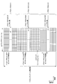
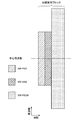
- FIG. 3 is a diagram illustrating an example of an NR downlink subframe in the present embodiment.
- a signal generated using the parameter set 1, the parameter set 0, and the parameter set 2 is FDM in the cell (system bandwidth).
- the diagram shown in FIG. 3 is also referred to as the NR downlink resource grid.
- the base station apparatus 1 can transmit an NR downlink physical channel and / or an NR downlink physical signal in a downlink subframe to the terminal apparatus 2.
- the terminal apparatus 2 can receive the NR downlink physical channel and / or the NR downlink physical signal in the downlink subframe from the base station apparatus 1.
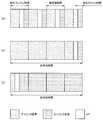
- FIG. 4 is a diagram illustrating an example of an uplink subframe of NR in the present embodiment.
- a signal generated using parameter set 1, parameter set 0, and parameter set 2 is FDM in a cell (system bandwidth).
- the diagram shown in FIG. 3 is also referred to as the NR uplink resource grid.
- the base station apparatus 1 can transmit an NR uplink physical channel and / or an NR uplink physical signal in an uplink subframe to the terminal apparatus 2.
- the terminal apparatus 2 can receive the NR uplink physical channel and / or the NR uplink physical signal in the uplink subframe from the base station apparatus 1.
- physical resources can be defined as follows.
- One slot is defined by a plurality of symbols.
- the physical signal or physical channel transmitted in each of the slots is represented by a resource grid.
- the resource grid may be defined by a plurality of subcarriers in the frequency direction and a plurality of OFDM symbols in the time direction.
- the resource grid may be defined by a plurality of subcarriers in the frequency direction and a plurality of OFDM symbols or SC-FDMA symbols in the time direction.
- the number of subcarriers or resource blocks may be determined depending on the cell bandwidth.
- the number of symbols in one slot may be determined by, for example, a CP (Cyclic Prefix) type.
- Examples of the CP type include a normal CP and an extended CP.
- the number of OFDM symbols or SC-FDMA symbols constituting one slot is seven.
- the extended CP the number of OFDM symbols or SC-FDMA symbols constituting one slot is six.
- Each element in the resource grid is called a resource element.
- the resource element is identified using a subcarrier index (number) and a symbol index (number).
- the OFDM symbol or SC-FDMA symbol is also simply referred to as a symbol.
- the resource block is used for mapping a certain physical channel (such as PDSCH or PUSCH) to a resource element.
- the resource block may include a virtual resource block and a physical resource block, for example.
- a certain physical channel is mapped to a virtual resource block.
- a virtual resource block is mapped to a physical resource block.
- One physical resource block is defined by, for example, a predetermined number of consecutive symbols in the time domain.
- One physical resource block is defined by, for example, a predetermined number of continuous subcarriers in the frequency domain. The number of symbols and the number of subcarriers in one physical resource block are determined based on the type of CP in the cell, the subcarrier spacing, and / or parameters set by higher layers.
- one physical resource block is composed of (7 ⁇ 12) resource elements.
- Physical resource blocks are numbered from 0 in the frequency domain. Further, two resource blocks in one subframe corresponding to the same physical resource block number are defined as physical resource block pairs (PRB pair, RB pair).
- An antenna port is defined so that a propagation channel carrying one symbol can be inferred from a propagation channel carrying another symbol at the same antenna port. For example, it can be assumed that different physical resources in the same antenna port are transmitted on the same propagation channel. In other words, a symbol at a certain antenna port can be demodulated by estimating a propagation channel using a reference signal at that antenna port. There is one resource grid per antenna port.
- An antenna port is defined by a reference signal. Each reference signal can define a plurality of antenna ports.
- An antenna port is identified or identified by an antenna port number. For example, antenna ports 0 to 3 are antenna ports to which CRS is transmitted. That is, the PDSCH transmitted through the antenna ports 0 to 3 can be demodulated by the CRS corresponding to the antenna ports 0 to 3.
- the two antenna ports satisfy a predetermined condition, they can be expressed as quasi-identical positions (QCL: Quasi co-location).
- the predetermined condition is that the wide-area characteristics of a propagation channel carrying a symbol at one antenna port can be inferred from the propagation channel carrying a symbol at another antenna port.
- Global characteristics include delay dispersion, Doppler spread, Doppler shift, average gain and / or average delay.
- the antenna port number may be defined differently for each RAT, or may be defined in common between RATs.
- antenna ports 0 to 3 in LTE are antenna ports through which CRS is transmitted.
- the antenna ports 0 to 3 can be antenna ports through which CRS similar to LTE is transmitted.
- an antenna port for transmitting a CRS similar to LTE can have an antenna port number different from antenna ports 0 to 3.
- the predetermined antenna port number can be applied to LTE and / or NR.
- the PBCH is used to broadcast an MIB (Master Information Block) that is broadcast information unique to the serving cell of the base station apparatus 1.
- MIB Master Information Block
- SFN is a radio frame number (system frame number).
- MIB is system information.
- the MIB includes information indicating SFN.
- PDCCH and EPDCCH are used to transmit downlink control information (DCI). Mapping of information bits of downlink control information is defined as a DCI format.
- the downlink control information includes a downlink grant (downlink grant) and an uplink grant (uplink grant).
- the downlink grant is also referred to as a downlink assignment or a downlink allocation.
- the PDCCH is transmitted by a set of one or more continuous CCEs (Control Channel Elements).
- the CCE is composed of nine REGs (Resource Element Groups).
- the REG is composed of four resource elements.
- EPDCCH is transmitted by a set of one or more continuous ECCEs (Enhanced Control Channel Elements).
- ECCE is composed of multiple EREGs (Enhanced Resource Element Group).
- the downlink grant is used for scheduling the PDSCH in a certain cell.
- the downlink grant is used for scheduling the PDSCH in the same subframe as the subframe in which the downlink grant is transmitted.
- the uplink grant is used for scheduling the PUSCH in a certain cell.
- the uplink grant is used for scheduling a single PUSCH in a subframe that is four or more times after the subframe in which the uplink grant is transmitted.
- the CRC parity bit is added to DCI.
- the CRC parity bit is scrambled by RNTI (Radio Network Temporary Identifier).
- the RNTI is an identifier that can be defined or set according to the purpose of the DCI.
- the RNTI is set as an identifier preliminarily specified in the specification, an identifier set as information specific to a cell, an identifier set as information specific to the terminal device 2, or information specific to a group belonging to the terminal device 2.
- Identifier For example, in monitoring PDCCH or EPDCCH, the terminal device 2 descrambles a CRC parity bit added to DCI with a predetermined RNTI and identifies whether the CRC is correct. If the CRC is correct, it can be seen that the DCI is the DCI for the terminal device 2.
- PDSCH is used to transmit downlink data (Downlink Shared Channel: DL-SCH).
- DL-SCH Downlink Shared Channel
- the PDSCH is also used for transmitting higher layer control information.
- a plurality of PDCCHs may be frequency, time and / or spatially multiplexed.
- a plurality of EPDCCHs may be frequency, time and / or spatially multiplexed.
- a plurality of PDSCHs may be frequency, time and / or spatially multiplexed.
- PDCCH, PDSCH and / or EPDCCH may be frequency, time and / or spatially multiplexed.
- the synchronization signal is used for the terminal apparatus 2 to synchronize the downlink frequency domain and / or time domain.
- the synchronization signal includes PSS (Primary Synchronization Signal) and SSS (Secondary Synchronization Signal).
- the synchronization signal is arranged in a predetermined subframe in the radio frame. For example, in the TDD scheme, the synchronization signal is arranged in subframes 0, 1, 5, and 6 in the radio frame. In the FDD scheme, the synchronization signal is arranged in subframes 0 and 5 in the radio frame.
- PSS may be used for coarse frame / symbol timing synchronization (time domain synchronization) and cell identification group identification.
- the SSS may be used for more accurate frame timing synchronization, cell identification, and CP length detection. That is, frame timing synchronization and cell identification can be performed by using PSS and SSS.
- the terminal apparatus 2 estimates downlink physical channel propagation path, propagation path correction, downlink CSI (Channel State Information) calculation, and / or positioning measurement of the terminal apparatus 2. Used to do
- URS related to PDSCH is transmitted in a subframe and a band used for transmission of PDSCH related to URS. URS is used to demodulate the PDSCH with which the URS is associated. The URS associated with the PDSCH is transmitted on one or more of the antenna ports 5, 7-14.
- the PDSCH is transmitted by an antenna port used for transmission of CRS or URS based on the transmission mode and the DCI format.
- the DCI format 1A is used for scheduling of PDSCH transmitted through an antenna port used for CRS transmission.
- the DCI format 2D is used for scheduling of the PDSCH transmitted through the antenna port used for URS transmission.
- DMRS related to EPDCCH is transmitted in subframes and bands used for transmission of EPDCCH related to DMRS.
- DMRS is used to demodulate the EPDCCH with which DMRS is associated.
- the EPDCCH is transmitted through an antenna port used for DMRS transmission.
- the DMRS associated with the EPDCCH is transmitted on one or more of the antenna ports 107-114.
- CSI-RS is transmitted in the set subframe. Resources for transmitting the CSI-RS are set by the base station apparatus 1.
- the CSI-RS is used for the terminal apparatus 2 to calculate downlink channel state information.
- the terminal device 2 performs signal measurement (channel measurement) using CSI-RS.
- CSI-RS supports configuration of some or all antenna ports of 1, 2, 4, 8, 12, 16, 24 and 32.
- CSI-RS is transmitted on one or more of antenna ports 15-46.
- the supported antenna port may be determined based on the terminal device capability of the terminal device 2, the setting of the RRC parameter, and / or the set transmission mode.
- ZP CSI-RS resources are set by higher layers. ZP CSI-RS resources may be transmitted with zero output power. That is, no ZP CSI-RS resource need be transmitted. PDSCH and EPDCCH are not transmitted in the resource set by ZP CSI-RS.
- ZP CSI-RS resources are used by neighboring cells to transmit NZP CSI-RS.
- ZP CSI-RS resources are used to measure CSI-IM.
- the ZP CSI-RS resource is a resource to which a predetermined channel such as PDSCH is not transmitted. In other words, a predetermined channel is mapped by excluding ZP CSI-RS resources (rate matching and puncturing).
- the PUCCH is a physical channel used for transmitting uplink control information (UPCI).
- the uplink control information includes downlink channel state information (CSI), scheduling request (SR) indicating a request for PUSCH resources, downlink data (Transport block: TB, Downlink-Shared Channel: DL).
- -SCH downlink data for HARQ-ACK.
- HARQ-ACK is also referred to as ACK / NACK, HARQ feedback, or response information.
- HARQ-ACK for downlink data indicates ACK, NACK, or DTX.
- PUSCH is a physical channel used for transmitting uplink data (Uplink-Shared Channel: UL-SCH).
- the PUSCH may also be used to transmit HARQ-ACK and / or channel state information along with uplink data. Also, the PUSCH may be used to transmit only channel state information or only HARQ-ACK and channel state information.
- PRACH is a physical channel used to transmit a random access preamble.
- the PRACH can be used for the terminal device 2 to synchronize with the base station device 1 in the time domain.
- PRACH is an initial connection establishment procedure (processing), a handover procedure, a connection re-establishment procedure, synchronization for uplink transmission (timing adjustment), and / or PUSCH resource request. Also used to indicate
- a plurality of PUCCHs are frequency, time, space and / or code multiplexed.
- a plurality of PUSCHs may be frequency, time, space and / or code multiplexed.
- PUCCH and PUSCH may be frequency, time, space and / or code multiplexed.
- the PRACH may be arranged over a single subframe or two subframes. A plurality of PRACHs may be code-multiplexed.
- UL-DMRS is related to transmission of PUSCH or PUCCH.
- UL-DMRS is time-multiplexed with PUSCH or PUCCH.
- the base station apparatus 1 may use UL-DMRS to perform PUSCH or PUCCH propagation path correction.
- PUSCH transmission also includes multiplexing and transmitting PUSCH and UL-DMRS.
- the transmission of PUCCH includes multiplexing and transmitting PUCCH and UL-DMRS.
- SRS is not related to PUSCH or PUCCH transmission.
- the base station apparatus 1 may use SRS in order to measure the uplink channel state.
- SRS is transmitted using the last symbol in the uplink subframe. That is, the SRS is arranged in the last symbol in the uplink subframe.
- the terminal device 2 can restrict simultaneous transmission of SRS and PUCCH, PUSCH and / or PRACH in a certain symbol of a certain cell.
- the terminal apparatus 2 transmits PUSCH and / or PUCCH using a symbol excluding the last symbol in the uplink subframe in an uplink subframe of a certain cell, and the last symbol in the uplink subframe. Can be used to transmit SRS. That is, in a certain uplink subframe of a certain cell, the terminal device 2 can transmit SRS, PUSCH and PUCCH.
- trigger type 0 SRS and trigger type 1 SRS are defined as SRSs having different trigger types.
- the trigger type 0 SRS is transmitted when parameters related to the trigger type 0 SRS are set by higher layer signaling.
- the trigger type 1 SRS is transmitted when a parameter related to the trigger type 1 SRS is set by higher layer signaling and transmission is requested by an SRS request included in the DCI format 0, 1A, 2B, 2C, 2D, or 4.
- the SRS request is included in both FDD and TDD for DCI formats 0, 1A, and 4, and is included only in TDD for DCI formats 2B, 2C, and 2D.
- Trigger type 0 SRS is also referred to as periodic SRS.
- Trigger type 1 SRS is also referred to as aperiodic SRS.
- FIG. 5 is a schematic block diagram showing the configuration of the base station apparatus 1 of the present embodiment.
- the base station apparatus 1 includes an upper layer processing unit 101, a control unit 103, a receiving unit 105, a transmitting unit 107, and a transmission / reception antenna 109.
- the reception unit 105 includes a decoding unit 1051, a demodulation unit 1053, a demultiplexing unit 1055, a radio reception unit 1057, and a channel measurement unit 1059.
- the transmission unit 107 includes an encoding unit 1071, a modulation unit 1073, a multiplexing unit 1075, a radio transmission unit 1077, and a downlink reference signal generation unit 1079.
- the base station apparatus 1 can support one or more RATs. Some or all of the units included in the base station apparatus 1 shown in FIG. 5 can be individually configured according to the RAT. For example, the reception unit 105 and the transmission unit 107 are individually configured with LTE and NR. Further, in the NR cell, a part or all of each unit included in the base station apparatus 1 shown in FIG. 5 can be individually configured according to a parameter set related to a transmission signal. For example, in a certain NR cell, the radio reception unit 1057 and the radio transmission unit 1077 can be individually configured according to a parameter set regarding a transmission signal.
- the upper layer processing unit 101 includes a medium access control (MAC) layer, a packet data integration protocol (Packet Data Convergence Protocol: PDCP) layer, a radio link control (Radio Link Control: RLC) layer, a radio resource control (Radio). Process Resource Control: RRC) layer. Further, the upper layer processing unit 101 generates control information for controlling the reception unit 105 and the transmission unit 107 and outputs the control information to the control unit 103.
- MAC medium access control
- PDCP Packet Data Convergence Protocol
- RLC Radio Link Control
- Radio Radio
- RRC Radio Resource Control
- the control unit 103 controls the reception unit 105 and the transmission unit 107 based on the control information from the higher layer processing unit 101.
- the control unit 103 generates control information for the upper layer processing unit 101 and outputs the control information to the upper layer processing unit 101.
- the control unit 103 inputs the decoded signal from the decoding unit 1051 and the channel estimation result from the channel measurement unit 1059.
- the control unit 103 outputs a signal to be encoded to the encoding unit 1071.
- the control unit 103 is used to control all or part of the base station apparatus 1.
- the upper layer processing unit 101 performs processing and management related to RAT control, radio resource control, subframe setting, scheduling control, and / or CSI report control.
- the processing and management in the upper layer processing unit 101 is performed for each terminal device or for the terminal devices connected to the base station device.
- the processing and management in the upper layer processing unit 101 may be performed only by the upper layer processing unit 101, or may be acquired from an upper node or another base station device. Further, the processing and management in the upper layer processing unit 101 may be performed individually according to the RAT. For example, the upper layer processing unit 101 individually performs processing and management in LTE and processing and management in NR.
- management related to RAT is performed.
- management related to LTE and / or management related to NR is performed.
- Management regarding NR includes setting and processing of parameter sets regarding transmission signals in the NR cell.
- radio resource control in the upper layer processing unit 101, generation and / or management of downlink data (transport block), system information, RRC message (RRC parameter), and / or MAC control element (CE) is performed. Done.
- subframe setting in the upper layer processing unit 101 subframe setting, subframe pattern setting, uplink-downlink setting, uplink reference UL-DL setting, and / or downlink reference UL-DL setting are managed. Is called.
- the subframe setting in higher layer processing section 101 is also referred to as base station subframe setting.
- the subframe setting in the higher layer processing unit 101 can be determined based on the uplink traffic volume and the downlink traffic volume. Further, the subframe setting in the upper layer processing unit 101 can be determined based on the scheduling result of the scheduling control in the upper layer processing unit 101.
- the frequency and subframe to which a physical channel is allocated, the physical channel's A coding rate, a modulation scheme, transmission power, and the like are determined.
- the control unit 103 generates control information (DCI format) based on the scheduling result of scheduling control in the upper layer processing unit 101.
- the CSI report of the terminal device 2 is controlled.
- the setting related to the CSI reference resource to be assumed for calculating the CSI in the terminal device 2 is controlled.
- the receiving unit 105 receives a signal transmitted from the terminal device 2 via the transmission / reception antenna 109 in accordance with control from the control unit 103, further performs reception processing such as separation, demodulation, and decoding, and receives the received information. Output to the control unit 103. Note that the reception process in the reception unit 105 is performed based on a setting specified in advance or a setting notified from the base station apparatus 1 to the terminal apparatus 2.
- the radio reception unit 1057 converts the uplink signal received via the transmission / reception antenna 109 into an intermediate frequency (down-conversion), removes unnecessary frequency components, and appropriately maintains the signal level. Control of amplification level, quadrature demodulation based on in-phase and quadrature components of received signal, conversion from analog signal to digital signal, removal of guard interval (Guard Interval: GI), and / or fast Fourier transform (Fast Fourier Transform) Extract frequency domain signals by Transform: FFT).
- GI Guard Interval
- FFT Fast Fourier transform
- the demultiplexing unit 1055 separates an uplink channel such as PUCCH or PUSCH and / or an uplink reference signal from the signal input from the radio reception unit 1057.
- the demultiplexing unit 1055 outputs the uplink reference signal to the channel measurement unit 1059.
- the demultiplexing unit 1055 performs channel compensation for the uplink channel from the channel estimation value input from the channel measurement unit 1059.
- the demodulation unit 1053 receives a received signal using a modulation scheme such as BPSK (Binary Phase Shift Keying), QPSK (Quadrature Phase Shift Keying), 16QAM (Quadrature Amplitude Modulation), 64QAM, or 256QAM for the modulation symbol of the uplink channel. Is demodulated.
- Demodulation section 1053 separates and demodulates the MIMO multiplexed uplink channel.
- the decoding unit 1051 performs a decoding process on the demodulated uplink channel encoded bits.
- the decoded uplink data and / or uplink control information is output to the control unit 103.
- Decoding section 1051 performs decoding processing for each transport block for PUSCH.
- the channel measurement unit 1059 measures the propagation path estimation value and / or channel quality from the uplink reference signal input from the demultiplexing unit 1055, and outputs it to the demultiplexing unit 1055 and / or the control unit 103.
- the channel measurement unit 1059 measures a channel estimation value for channel compensation for PUCCH or PUSCH using UL-DMRS, and measures the channel quality in the uplink using SRS.
- the transmission unit 107 performs transmission processing such as encoding, modulation, and multiplexing on the downlink control information and the downlink data input from the higher layer processing unit 101 according to the control from the control unit 103. For example, the transmission unit 107 generates and multiplexes PHICH, PDCCH, EPDCCH, PDSCH, and a downlink reference signal, and generates a transmission signal. Note that the transmission processing in the transmission unit 107 is based on settings specified in advance, settings notified from the base station apparatus 1 to the terminal apparatus 2, or settings notified via the PDCCH or EPDCCH transmitted in the same subframe. Done.
- the encoding unit 1071 performs HARQ indicator (HARQ-ACK), downlink control information, and downlink data input from the control unit 103 with predetermined encoding such as block encoding, convolutional encoding, and turbo encoding. Encoding is performed using a method.
- the modulation unit 1073 modulates the coded bits input from the coding unit 1071 with a predetermined modulation method such as BPSK, QPSK, 16QAM, 64QAM, 256QAM.
- the downlink reference signal generation unit 1079 generates a downlink reference signal based on a physical cell identifier (PCI), an RRC parameter set in the terminal device 2, and the like.
- Multiplexer 1075 multiplexes the modulation symbols and downlink reference signals for each channel and arranges them in a predetermined resource element.
- the radio transmission unit 1077 converts the signal from the multiplexing unit 1075 into a signal in the time domain by inverse fast Fourier transform (IFFT), adds a guard interval, generates a baseband digital signal, Performs conversion to analog signal, quadrature modulation, conversion from intermediate frequency signal to high frequency signal (up-convert), removal of excess frequency components, power amplification, etc. to generate a transmission signal .
- IFFT inverse fast Fourier transform
- up-convert up-convert
- removal of excess frequency components power amplification, etc.
- FIG. 6 is a schematic block diagram showing the configuration of the terminal device 2 of the present embodiment.
- the terminal device 2 includes an upper layer processing unit 201, a control unit 203, a reception unit 205, a transmission unit 207, and a transmission / reception antenna 209.
- the reception unit 205 includes a decoding unit 2051, a demodulation unit 2053, a demultiplexing unit 2055, a radio reception unit 2057, and a channel measurement unit 2059.
- the transmission unit 207 includes an encoding unit 2071, a modulation unit 2073, a multiplexing unit 2075, a radio transmission unit 2077, and an uplink reference signal generation unit 2079.
- the terminal device 2 can support one or more RATs. Part or all of the units included in the terminal device 2 illustrated in FIG. 6 can be individually configured according to the RAT.
- the reception unit 205 and the transmission unit 207 are individually configured with LTE and NR.
- some or all of the units included in the terminal apparatus 2 shown in FIG. 6 can be individually configured according to the parameter set related to the transmission signal.
- the radio reception unit 2057 and the radio transmission unit 2077 can be individually configured according to a parameter set related to a transmission signal.
- the higher layer processing unit 201 outputs the uplink data (transport block) to the control unit 203.
- the upper layer processing unit 201 includes a medium access control (MAC) layer, a packet data integration protocol (Packet Data Convergence Protocol: PDCP) layer, a radio link control (Radio Link Control: RLC) layer, a radio resource control (Radio). Process Resource Control: RRC) layer. Further, the upper layer processing unit 201 generates control information for controlling the reception unit 205 and the transmission unit 207 and outputs the control information to the control unit 203.
- MAC medium access control
- PDCP Packet Data Convergence Protocol
- RLC Radio Link Control
- RRC Radio Resource Control
- the control unit 203 controls the reception unit 205 and the transmission unit 207 based on the control information from the higher layer processing unit 201.
- the control unit 203 generates control information for the upper layer processing unit 201 and outputs the control information to the upper layer processing unit 201.
- the control unit 203 inputs the decoded signal from the decoding unit 2051 and the channel estimation result from the channel measurement unit 2059.
- the control unit 203 outputs a signal to be encoded to the encoding unit 2071. Further, the control unit 203 may be used to control all or part of the terminal device 2.
- the upper layer processing unit 201 performs processing and management related to RAT control, radio resource control, subframe setting, scheduling control, and / or CSI report control.
- the processing and management in the upper layer processing unit 201 are performed based on settings specified in advance and / or settings based on control information set or notified from the base station apparatus 1.
- the control information from the base station apparatus 1 includes an RRC parameter, a MAC control element, or DCI.
- the processing and management in the upper layer processing unit 201 may be performed individually according to the RAT.
- the upper layer processing unit 201 individually performs processing and management in LTE and processing and management in NR.
- management related to RAT is performed.
- management related to LTE and / or management related to NR is performed.
- Management regarding NR includes setting and processing of parameter sets regarding transmission signals in the NR cell.
- radio resource control in the higher layer processing unit 201 management of setting information in the own apparatus is performed.
- radio resource control in the upper layer processing unit 201 generation and / or management of uplink data (transport block), system information, RRC message (RRC parameter), and / or MAC control element (CE) is performed. Done.
- the subframe setting in the upper layer processing unit 201 the subframe setting in the base station apparatus 1 and / or a base station apparatus different from the base station apparatus 1 is managed.
- the subframe configuration includes uplink or downlink configuration, subframe pattern configuration, uplink-downlink configuration, uplink reference UL-DL configuration, and / or downlink reference UL-DL configuration for the subframe.
- the subframe setting in the higher layer processing unit 201 is also referred to as terminal subframe setting.
- control information for performing control related to scheduling for the reception unit 205 and the transmission unit 207 is generated based on DCI (scheduling information) from the base station apparatus 1.
- control related to CSI reporting to the base station apparatus 1 is performed.
- the channel measurement unit 2059 controls settings related to CSI reference resources that are assumed to calculate CSI.
- resources (timing) used for reporting CSI are controlled based on DCI and / or RRC parameters.
- the receiving unit 205 receives the signal transmitted from the base station apparatus 1 via the transmission / reception antenna 209 according to the control from the control unit 203, and further performs reception processing such as separation, demodulation, decoding, and the like. Is output to the control unit 203. Note that the reception process in the reception unit 205 is performed based on a predetermined setting or a notification or setting from the base station apparatus 1.
- the radio reception unit 2057 converts the uplink signal received via the transmission / reception antenna 209 to an intermediate frequency (down-conversion), removes unnecessary frequency components, and appropriately maintains the signal level. Control of amplification level, quadrature demodulation based on in-phase and quadrature components of received signal, conversion from analog signal to digital signal, removal of guard interval (Guard Interval: GI), and / or fast Fourier transform (Fast Fourier Transform) Extracts frequency domain signals using Transform (FFT).
- FFT Fast Fourier transform
- the demultiplexing unit 2055 separates a downlink channel such as PHICH, PDCCH, EPDCCH, or PDSCH, a downlink synchronization signal, and / or a downlink reference signal from the signal input from the radio reception unit 2057.
- the demultiplexing unit 2055 outputs the downlink reference signal to the channel measurement unit 2059.
- the demultiplexing unit 2055 performs channel compensation for the downlink channel from the channel estimation value input from the channel measurement unit 2059.
- the demodulator 2053 demodulates the received signal using a modulation scheme such as BPSK, QPSK, 16QAM, 64QAM, 256QAM, etc., with respect to the downlink channel modulation symbols.
- the demodulator 2053 separates and demodulates the MIMO multiplexed downlink channel.
- the decoding unit 2051 performs a decoding process on the demodulated downlink channel encoded bits.
- the decoded downlink data and / or downlink control information is output to the control unit 203.
- the decoding unit 2051 performs a decoding process for each transport block on the PDSCH.
- the channel measurement unit 2059 measures the estimated value of the propagation path and / or the channel quality from the downlink reference signal input from the demultiplexing unit 2055 and outputs it to the demultiplexing unit 2055 and / or the control unit 203.
- the downlink reference signal used for measurement by the channel measurement unit 2059 may be determined based on at least the transmission mode set by the RRC parameter and / or other RRC parameters.
- DL-DMRS measures an estimated value of a propagation path for performing propagation path compensation for PDSCH or EPDCCH.
- CRS measures a channel estimation value for performing channel compensation for PDCCH or PDSCH and / or a channel in the downlink for reporting CSI.
- CSI-RS measures the channel in the downlink for reporting CSI.
- the channel measurement unit 2059 calculates RSRP (Reference Signal Received Power) and / or RSRQ (Reference Signal Received Quality) based on the CRS, CSI-RS, or detection signal, and outputs it to the upper layer processing unit
- the transmission unit 207 performs transmission processing such as encoding, modulation, and multiplexing on the uplink control information and the uplink data input from the higher layer processing unit 201 according to the control from the control unit 203. For example, the transmission unit 207 generates and multiplexes an uplink channel such as PUSCH or PUCCH and / or an uplink reference signal, and generates a transmission signal. Note that the transmission processing in the transmission unit 207 is performed based on settings specified in advance or settings or notifications from the base station apparatus 1.
- the encoding unit 2071 encodes the HARQ indicator (HARQ-ACK), the uplink control information, and the uplink data input from the control unit 203 with predetermined encoding such as block encoding, convolutional encoding, and turbo encoding. Encoding is performed using a method.
- the modulation unit 2073 modulates the coded bits input from the coding unit 2071 using a predetermined modulation method such as BPSK, QPSK, 16QAM, 64QAM, or 256QAM.
- the uplink reference signal generation unit 2079 generates an uplink reference signal based on the RRC parameter set in the terminal device 2 and the like.
- Multiplexing section 2075 multiplexes the modulation symbols and uplink reference signals for each channel and arranges them in a predetermined resource element.
- the radio transmission unit 2077 converts the signal from the multiplexing unit 2075 into a time domain signal by Inverse Fast Fourier Transform (IFFT), adds a guard interval, generates a baseband digital signal, Performs conversion to analog signal, quadrature modulation, conversion from intermediate frequency signal to high frequency signal (up-convert), removal of excess frequency components, power amplification, etc. to generate a transmission signal .
- IFFT Inverse Fast Fourier Transform
- the transmission signal output from the wireless transmission unit 2077 is transmitted from the transmission / reception antenna 209.
- the base station apparatus 1 and the terminal apparatus 2 can use various methods for control information signaling (notification, notification, and setting), respectively.
- Signaling of control information can be performed in various layers.
- the signaling of control information includes physical layer signaling that is signaling through the physical layer (layer), RRC signaling that is signaling through the RRC layer, and MAC signaling that is signaling through the MAC layer.
- the RRC signaling is dedicated RRC signaling (Dedicated RRC signaling) for notifying control information unique to the terminal device 2 or common RRC signaling (Common RRC signaling) for notifying control information unique to the base station device 1.
- Signaling used by higher layers as viewed from the physical layer, such as RRC signaling and MAC signaling is also referred to as upper layer signaling.
- RRC signaling is realized by signaling RRC parameters.
- MAC signaling is realized by signaling a MAC control element.
- Physical layer signaling is realized by signaling downlink control information (DCI: Downlink Control Information) or uplink control information (UCI: Uplink Control Information).
- DCI Downlink Control Information
- UCI Uplink Control Information
- the RRC parameter and the MAC control element are transmitted using PDSCH or PUSCH.
- DCI is transmitted using PDCCH or EPDCCH.
- UCI is transmitted using PUCCH or PUSCH.
- RRC signaling and MAC signaling are used for signaling semi-static control information and are also referred to as semi-static signaling.
- Physical layer signaling is used to signal dynamic control information and is also referred to as dynamic signaling.
- DCI is used for PDSCH scheduling or PUSCH scheduling.
- the UCI is used for CSI reporting, HARQ-ACK reporting, and / or scheduling request (SR).
- SR scheduling request
- the DCI is notified using a DCI format having a predefined field.
- predetermined information bits are mapped.
- DCI notifies downlink scheduling information, uplink scheduling information, side link scheduling information, aperiodic CSI report request, or uplink transmission power command.
- the DCI format monitored by the terminal device 2 is determined by the transmission mode set for each serving cell. That is, a part of the DCI format monitored by the terminal device 2 can be different depending on the transmission mode.
- the terminal device 2 in which the downlink transmission mode 1 is set monitors the DCI format 1A and the DCI format 1.
- the terminal device 2 in which the downlink transmission mode 4 is set monitors the DCI format 1A and the DCI format 2.
- the terminal device 2 in which the uplink transmission mode 1 is set monitors the DCI format 0.
- the terminal device 2 in which the uplink transmission mode 2 is set monitors the DCI format 0 and the DCI format 4.
- the control region in which the PDCCH that notifies the DCI for the terminal device 2 is not notified, and the terminal device 2 detects the DCI for the terminal device 2 by blind decoding (blind detection). Specifically, the terminal device 2 monitors a set of PDCCH candidates in the serving cell. Monitoring means attempting to decode with all monitored DCI formats for each of the PDCCHs in the set. For example, the terminal device 2 tries to decode all the aggregation levels, PDCCH candidates, and DCI formats that may be transmitted to the terminal device 2. The terminal device 2 recognizes the DCI (PDCCH) that has been successfully decoded (detected) as the DCI (PDCCH) for the terminal device 2.
- PDCCH DCI
- Cyclic Redundancy Check is added to DCI.
- the CRC is used for DCI error detection and DCI blind detection.
- CRC CRC parity bit
- RNTI Radio Network Temporary Identifier
- the terminal device 2 detects whether it is DCI for the terminal device 2 based on the RNTI. Specifically, the terminal device 2 descrambles the bit corresponding to the CRC with a predetermined RNTI, extracts the CRC, and detects whether the corresponding DCI is correct.
- RNTI is specified or set according to the purpose and application of DCI.
- RNTI is C-RNTI (Cell-RNTI), SPS C-RNTI (Semi Persistent Scheduling C-RNTI), SI-RNTI (System Information-RNTI), P-RNTI (Paging-RNTI), RA-RNTI (Random Access) -RNTI), TPC-PUCCH-RNTI (Transmit Power Control-PUCCH-RNTI), TPC-PUSCH-RNTI (Transmit Power Control-PUSCH-RNTI), Temporary C-RNTI, M-RNTI (MBMS (Multimedia Broadcast Multicast Services) ) -RNTI), eIMTA-RNTI, CC-RNTI.
- C-RNTI Cell-RNTI
- SPS C-RNTI Semi Persistent Scheduling C-RNTI
- SI-RNTI System Information-RNTI
- P-RNTI Paging-RNTI
- RA-RNTI Random Access
- C-RNTI and SPS C-RNTI are RNTIs specific to the terminal device 2 in the base station device 1 (cell), and are identifiers for identifying the terminal device 2.
- C-RNTI is used to schedule PDSCH or PUSCH in a certain subframe.
- the SPS C-RNTI is used to activate or release periodic scheduling of resources for PDSCH or PUSCH.
- a control channel having a CRC scrambled by SI-RNTI is used for scheduling an SIB (System Information Block).
- SIB System Information Block
- a control channel with a CRC scrambled with P-RNTI is used to control paging.
- a control channel having a CRC scrambled with RA-RNTI is used to schedule a response to RACH.
- a control channel having a CRC scrambled by TPC-PUCCH-RNTI is used for power control of PUCCH.
- a control channel having a CRC scrambled by TPC-PUSCH-RNTI is used to perform power control of PUSCH.
- a control channel having a CRC scrambled with Temporary C-RNTI is used by a mobile station apparatus for which C-RNTI is not set or recognized.
- a control channel with CRC scrambled with M-RNTI is used to schedule MBMS.
- a control channel having a CRC scrambled by eIMTA-RNTI is used for notifying information on TDD UL / DL configuration of a TDD serving cell in dynamic TDD (eIMTA).
- a control channel (DCI) having a CRC scrambled with CC-RNTI is used in the LAA secondary cell to notify the setting of a dedicated OFDM symbol.
- DCI control channel
- the DCI format may be scrambled not only by the above RNTI but also by a new RNTI.
- Scheduling information includes information for performing scheduling in units of resource blocks or resource block groups as frequency domain scheduling.
- the resource block group is a set of consecutive resource blocks, and indicates resources allocated to terminal devices to be scheduled.
- the size of the resource block group is determined according to the system bandwidth.
- DCI is transmitted using a control channel such as PDCCH or EPDCCH.
- the terminal device 2 monitors a set of PDCCH candidates and / or a set of EPDCCH candidates of one or more activated serving cells configured by RRC signaling.
- monitoring means trying to decode PDCCH and / or EPDCCH in a set corresponding to all monitored DCI formats.
- the PDCCH candidate set or EPDCCH candidate set is also called a search space.
- a search space a shared search space (CSS) and a terminal-specific search space (USS) are defined.
- the CSS may be defined only for the search space for PDCCH.
- CSS Common Search Space
- the USS UE-specific Search Space
- USS is a search space set using at least parameters specific to the terminal device 2. Therefore, USS is a search space unique to the terminal device 2, and the base station device 1 can individually transmit a control channel unique to the terminal device 2 by the USS. Therefore, the base station apparatus 1 can efficiently map control channels unique to a plurality of terminal apparatuses.
- USS may be set so as to be used in common by a plurality of terminal devices. Since a common USS is set for a plurality of terminal devices, parameters unique to the terminal device 2 are set so as to have the same value among the plurality of terminal devices. For example, a unit set to the same parameter among a plurality of terminal devices is a cell, a transmission point, a group of predetermined terminal devices, or the like.
- the search space for each aggregation level is defined by a set of PDCCH candidates.
- Each PDCCH is transmitted using a set of one or more CCEs (Control Channel Elements).
- the number of CCEs used for one PDCCH is also referred to as an aggregation level. For example, the number of CCEs used for one PDCCH is 1, 2, 4 or 8.
- the number of PDCCH candidates is determined based on at least the search space and the aggregation level. For example, in CSS, the number of PDCCH candidates at aggregation levels 4 and 8 is 4 and 2, respectively. For example, in USS, the numbers of PDCCH candidates in aggregations 1, 2, 4, and 8 are 6, 6, 2, and 2, respectively.
- the base station device 1 can use a plurality of methods as a method of assigning PDSCH and / or PUSCH resources to the terminal device 2.
- Resource allocation methods include dynamic scheduling, semi-persistent scheduling, multi-subframe scheduling, and cross-subframe scheduling.
- one DCI performs resource allocation in one subframe. Specifically, PDCCH or EPDCCH in a certain subframe performs scheduling for PDSCH in that subframe. PDCCH or EPDCCH in a certain subframe performs scheduling for PUSCH in a predetermined subframe after that subframe.
- one DCI performs resource allocation in one or more subframes.
- PDCCH or EPDCCH in a certain subframe performs scheduling for PDSCH in one or more subframes after a predetermined number of subframes.
- PDCCH or EPDCCH in a certain subframe performs scheduling for PUSCH in one or more subframes after a predetermined number of times from the subframe.
- the predetermined number can be an integer greater than or equal to zero.
- the predetermined number may be defined in advance or may be determined based on physical layer signaling and / or RRC signaling.
- consecutive subframes may be scheduled, or subframes having a predetermined period may be scheduled.
- the number of subframes to be scheduled may be predetermined or may be determined based on physical layer signaling and / or RRC signaling.
- one DCI performs resource allocation in one subframe.
- PDCCH or EPDCCH in a certain subframe performs scheduling for PDSCH in one subframe that is a predetermined number after that subframe.
- PDCCH or EPDCCH in a certain subframe performs scheduling for PUSCH in one subframe after a predetermined number of times from the subframe.
- the predetermined number can be an integer greater than or equal to zero.
- the predetermined number may be defined in advance or may be determined based on physical layer signaling and / or RRC signaling.
- continuous subframes may be scheduled, or subframes having a predetermined period may be scheduled.
- one DCI performs resource allocation in one or more subframes.
- the terminal device 2 sets information related to SPS by RRC signaling and detects PDCCH or EPDCCH for enabling SPS, the terminal device 2 enables processing related to SPS, and performs predetermined PDSCH and / or PUSCH based on the setting related to SPS.
- the terminal apparatus 2 detects PDCCH or EPDCCH for releasing SPS when SPS is valid, the terminal apparatus 2 releases (invalidates) SPS and stops receiving predetermined PDSCH and / or PUSCH.
- the release of the SPS may be performed based on a case where a predetermined condition is satisfied. For example, the SPS is released when a predetermined number of empty transmission data is received. Empty transmission of data for releasing SPS corresponds to MAC PDU (Protocol Data Unit) including zero MAC SDU (Service Data Unit).
- MAC PDU Protocol Data Unit
- MAC SDU Service Data Unit
- Information related to SPS by RRC signaling includes SPS C-RNTI, which is the RNTI of SPS, information related to PDSCH scheduled period (interval), information related to PUSCH scheduled period (interval), and settings for releasing SPS.
- SPS C-RNTI is the RNTI of SPS
- information related to PDSCH scheduled period (interval) information related to PUSCH scheduled period (interval)
- settings for releasing SPS information related to SPS by RRC signaling.
- SPS is supported only for primary cells and / or primary secondary cells.
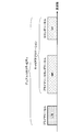
- FIG. 15 shows an example of a frame configuration of self-contained transmission in this embodiment.
- one transmission / reception is configured in the order of downlink transmission, GP, and continuous downlink transmission from the top.
- the continuous downlink transmission includes at least one downlink control information and DMRS.
- the downlink control information instructs reception of a downlink physical channel included in the continuous downlink transmission or transmission of an uplink physical channel included in the continuous uplink transmission.
- the terminal device 2 tries to receive the downlink physical channel based on the downlink control information.
- the terminal device 2 transmits the reception success or failure (decoding success or failure) of the downlink physical channel through the uplink control channel included in the uplink transmission allocated after the GP.
- the downlink control information instructs the transmission of the uplink physical channel
- the uplink physical channel transmitted based on the downlink control information is included in the uplink transmission for transmission.
- downlink low-delay communication can be realized by notifying the success or failure of downlink reception by uplink transmission immediately after.
- the unit slot time is the minimum time unit that defines downlink transmission, GP, or uplink transmission. Unit slot time is reserved for either downlink transmission, GP, or uplink transmission. The unit slot time does not include both downlink transmission and uplink transmission.
- the unit slot time may be the minimum transmission time of a channel associated with the DMRS included in the unit slot time.
- One unit slot time is defined by, for example, an NR sampling interval (T s ) or an integer multiple of a symbol length.
- the unit frame time may be a minimum time specified by scheduling.
- the unit frame time may be a minimum unit in which a transport block is transmitted.
- the unit slot time may be the maximum transmission time of a channel associated with the DMRS included in the unit slot time.
- the unit frame time may be a unit time for determining the uplink transmission power in the terminal device 2.
- the unit frame time may be referred to as a subframe.
- One unit frame time is defined by, for example, an NR sampling interval (T s ), a symbol length, or an integer multiple of a unit slot time.
- the transmission / reception time is one transmission / reception time. Between one transmission / reception and another transmission / reception, time (gap) in which no physical channel and physical signal are transmitted is occupied. The terminal device 2 may not average the CSI measurement between different transmissions and receptions.
- the transmission / reception time may be referred to as TTI.
- One transmission / reception time is defined by, for example, an NR sampling interval (T s ), a symbol length, a unit slot time, or an integer multiple of a unit frame time.
- Uplink RS of NR in this embodiment examples include NR-SRS.
- An example of NR-SRS is described below. Note that features not specified below can be regarded as the same as SRS in LTE.
- NR-SRS may not be transmitted in the last symbol in a subframe or slot.
- the NR-SRS may be transmitted using the first symbol or a middle symbol in a subframe or slot.
- the NR-SRS may be transmitted continuously with a plurality of symbols.
- the NR-SRS may be transmitted in the last few symbols in a subframe or slot.
- NR antenna configuration in this embodiment As the NR antenna, a digital antenna configuration, an analog antenna configuration, and a hybrid antenna configuration in which the digital antenna configuration and the analog antenna configuration are combined are assumed.
- the digital antenna configuration is a configuration in which the antenna weight is controlled by a digital circuit (baseband region) for each antenna element.
- FIG. 8 is a schematic block diagram illustrating an example of a digital antenna configuration according to the present embodiment.
- the configuration of base station apparatus 1 in FIG. 5 is illustrated focusing on the configurations of multiplexing section 1075, radio transmission section 1077, and antenna section 109. Further, in FIG. 8, illustrations of components unnecessary for the description of the basic configuration are omitted, but it is assumed that the components described in FIG. 5 are provided in each unit.
- the multiplexing unit 1075 includes a precoding unit. That is, in the digital antenna configuration, the precoding unit multiplies the transmission signal corresponding to each antenna element by the antenna weight to form a beam.
- the digital antenna configuration it is possible to perform flexible phase control for each antenna element, and it is possible to generate different beams in the frequency domain.
- the digital antenna configuration tends to be complicated.
- FIG. 9 is a schematic block diagram showing an example of an analog antenna configuration in the present embodiment.
- FIG. 9 similarly to FIG. 8, attention is paid to the configuration of the multiplexing unit 1075, the wireless transmission unit 1077, and the antenna unit 109 in the configuration of the base station apparatus 1 of FIG. 5.
- FIG. 9 illustrations of components that are not necessary for the description of the basic configuration are omitted, but it is assumed that the components described in FIG. 5 are provided in each unit.
- the wireless transmission unit 1077 includes a phase control unit.
- a beam is formed by rotating the phase of the transmission signal in the analog region (RF region).
- ⁇ Flexible beam control is complicated in processing to control the phase in the analog domain, but the configuration tends to be simple.
- the antenna switching configuration is part of an analog antenna configuration.
- the hybrid antenna configuration is a combination of a digital antenna configuration and an analog antenna configuration, and has both a phase control element in the analog domain and a phase control element in the digital domain.
- the hybrid antenna configuration has characteristics that are intermediate between the digital antenna configuration and the analog antenna configuration in terms of beamforming performance and configuration complexity.
- ⁇ NR beam operation method in this embodiment In NR, two types of schemes are assumed, single beam operation and multiple beam operation.
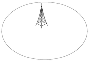
- FIG. 10 is an explanatory diagram for explaining an outline of an example of single beam operation.
- Single beam operation is a scheme in which a predetermined cell coverage is covered by one beam (that is, operated by one beam). Specifically, within a predetermined cell coverage, a cell-specific physical channel or physical signal is transmitted by one beam.
- LTE can be considered single beam operation.
- FIG. 11 is an explanatory diagram for explaining an outline of an example of the multiple beam operation.
- the multiple beam operation is a method in which a predetermined cell coverage is covered by one or more beams (that is, operated by one or more beams). Specifically, a cell-specific physical channel or physical signal is transmitted by a plurality of beams. For example, in analog beam forming and hybrid beam forming, a beam in a predetermined direction is transmitted in a predetermined time instance, and it is difficult to transmit in a beam other than the beam in the predetermined direction. Therefore, for example, by switching time instances, beams in a plurality of directions are switched, and a wide area can be covered.
- a predetermined beam in which a cell-specific physical channel or physical signal is transmitted is transmitted in one time instance (time resource). Also, different beams are transmitted at different time instances.
- a plurality of beams are switched and operated in a plurality of time instances. Switching between multiple beams at multiple time instances is referred to as beam sweep.
- a beam can be restated in terms such as a channel, a path, an antenna, and an antenna port. That is, transmission using different beams can be said to be transmission using different channels, paths, antennas, or antenna ports. Furthermore, the beam can be assumed as a virtual cell. The terminal device can recognize different beams transmitted from the same cell as different virtual cells or virtual carriers.
- information that can be paraphrased as a beam such as the channel, path, antenna, and antenna port, information related to control of the beam (for example, information related to antenna settings, etc.), etc. Also referred to as “antenna information”. That is, a signal transmitted by a predetermined beam can be regarded as being associated with antenna information corresponding to the beam.
- the system preferably selects an appropriate beam for each downlink and uplink. Specifically, it is preferable that an appropriate beam is selected for each of the downlink transmission beam of the base station apparatus and the downlink reception beam of the terminal apparatus. Moreover, it is preferable that an appropriate beam is selected for each of the uplink transmission beam of the terminal apparatus and the uplink reception beam of the base station apparatus.
- the base station apparatus can recognize an appropriate downlink transmission beam based on a report or feedback information from a terminal apparatus that receives a signal transmitted from the base station apparatus.
- the base station apparatus transmits a predetermined known signal a plurality of times using different downlink transmission beams.
- the terminal apparatus determines an appropriate downlink transmission beam from each of the known signals transmitted a plurality of times by different downlink transmission beams based on reception strength or reception quality, and sets the appropriate downlink transmission beam. Corresponding information is reported or fed back to the base station apparatus. Thereby, the base station apparatus can recognize an appropriate downlink transmission beam.
- the known signal include various reference signals such as NR-SS, MRS, BRS, NR-CSI-RS, and NR-DM-RS.
- the base station apparatus can recognize an appropriate downlink transmission beam based on an appropriate uplink reception beam of the base station apparatus.
- the terminal apparatus can recognize an appropriate uplink transmission beam based on a report or feedback information from a base station apparatus that receives a signal transmitted from the terminal apparatus.
- a process in which the terminal apparatus recognizes an appropriate uplink transmission beam is shown.
- the terminal apparatus transmits a predetermined known signal a plurality of times using different uplink transmission beams.
- the base station apparatus determines an appropriate uplink transmission beam from each of the known signals transmitted a plurality of times by different uplink transmission beams based on reception strength or reception quality, and the appropriate uplink transmission beam Information corresponding to is reported or notified to the terminal device. Thereby, the terminal device can recognize an appropriate uplink transmission beam.
- the known signal include various reference signals such as NR-PRACH, NR-SRS, and NR-DM-RS.
- the terminal apparatus can recognize an appropriate uplink transmission beam based on an appropriate downlink reception beam of the terminal apparatus.
- NR synchronization signal in this embodiment is used for the terminal device to synchronize the downlink frequency domain and / or time domain.
- a synchronization signal used in NR is called NR-SS (NR-Synchronization Signal).
- NR-SS is composed of at least NR-PSS (NR-Primary Synchronization Signal) and NR-SSS (NR-Secondary Synchronization Signal). Note that the NR-SS may be configured to include an NR-TSS (NR-Third Synchronization Signal).
- the NR-SS is preferably constant regardless of the system bandwidth over a predetermined frequency range (frequency band).
- NR-PSS is used for initial synchronization of symbol boundaries for at least NR cells.
- the NR-PSS may be used for detection of a part of the NR cell identifier or may be used for demodulation for the NR-SSS.
- the NR-PSS sequence is configured using, for example, an M sequence or a Zadoff-Chu sequence.
- the terminal device does not detect NR-PSS using other reference signals. Further, the terminal device may not assume that the NR-PSS is transmitted using the same TRP (Transmission and Reception Point) and antenna port as any other downlink reference signal.
- TRP Transmission and Reception Point
- NR-SSS is used to detect at least an NR cell identifier or a part of an NR cell identifier.
- the NR-SSS is located and detected in a fixed time and frequency resource relationship with respect to the resource location of the NR-PSS.
- the resource relationship is constant regardless of the duplex method or the beam operation method.
- the type of NR-SSS sequence is preferably an M sequence, but may be a Zadoff-Chu sequence, a Gold sequence, or the like. Also, a plurality of types of the series may be used in combination, or a plurality of series of the same type and different generation formulas may be used in combination.
- the terminal device may perform NR-SSS detection using channel state information obtained by NR-PSS detection and / or information on the NR cell.
- the terminal device may assume that NR-SSS is transmitted through the same antenna port as that of NR-PSS.
- NR-TSS may be used to notify the index of the synchronization signal block.
- the NR-TSS may be used to notify the beam index.
- the NR-TSS may be used to notify the number of repetitions of the synchronization signal block.
- the NR-TSS is used to notify whether a part of or all of the synchronization signal block including the NR-TSS and other synchronization signals in the synchronization signal burst and / or the NR-PBCH are the same. May be.
- NR-TSS may be used for demodulation of NR-PBCH. That is, NR-TSS may be transmitted on the same antenna port as NR-PBCH.
- the terminal device assumes that NR-PBCH and NR-TSS are QCL. Note that the NR-TSS may be transmitted by being included in an OFDM symbol in which the NR-PBCH is transmitted.
- the NR-TSS series is preferably an M series or a Gold series.
- NR-SS may be used to measure the quality of the NR cell in which the NR-SS is transmitted.
- the quality of the NR cell is, for example, RSRP, RSRQ, RSSI (Received Signal Strength Indicator), SNR (Signal to Noise Ratio), and / or SINR (Signal to Interference plus Noise Ratio).
- NR-SS is transmitted using a predetermined subcarrier interval.
- the predetermined subcarrier interval is uniquely defined for the frequency band (operating band).
- NR Broadcast Channel in the Present Embodiment>
- the broadcast channel is referred to as NR-PBCH.
- NR-PBCH is used to broadcast a part of system information.
- the NR-PBCH is not scheduled by other control information.
- the information carried on the NR-PBCH is a fixed payload size.
- the NR-PBCH is transmitted periodically. That information carried on the NR-PBCH is called first NR system information or NR-MIB.
- NR-MIB included in NR-PBCH is encoded by a polar code.
- the NR-MIB may be encoded by an LDPC (Low-Density Parity Check) code.
- the NR-MIB may be encoded by a convolutional code.
- the NR-PBCH may be scrambled using the NR cell identifier.
- the terminal apparatus descrambles the NR-PBCH using the NR cell identifier.
- the NR-PBCH may be scrambled using another identifier obtained by the NR-SS. Examples of other identifiers include a beam index and a time index.
- NR-PBCH resource mapping is assigned in order from the frequency direction.
- modulated symbols are sequentially assigned to the subcarriers of the first symbol.
- the modulated symbols are sequentially assigned to the subcarriers of the next symbol. Such a process is repeated, and modulated symbols are allocated to all resource elements reserved for NR-PBCH.
- the subcarrier interval of NR-PBCH is preferably the same as the subcarrier interval of NR-SS.
- NR-PBCH may be multiplexed with an RS for demodulating NR-PBCH and transmitted.
- the NR-PBCH may be demodulated using the RS.
- NR-PBCH may be demodulated using NR-SS.
- the NR-PBCH may be demodulated using MRS.
- NR-PBCH is transmitted in the primary cell, for example.
- the NR-PBCH is transmitted in a stand-alone cell. Note that the NR-PBCH may not be transmitted in the secondary cell. Further, the NR-PBCH may not be transmitted in a non-standalone cell.
- the control subband (control resource set) is a physical resource in which PDCCH and NR-PDCCH are arranged. Examples include a control subband (common control subband) set in common to the terminal devices connected to the base station, and a control subband (terminal specific subband) set in each terminal device.
- the common control subband is used for a PDCCH that controls a PDSCH transmitted in common to terminals of a cell or a terminal apparatus group.
- the common control subband is set by NR-MIB.
- NR-PDCCH As an example of the NR-PDCCH sent by the common control subband, there is NR-PDCCH that schedules the NR-PDSCH carrying the second and subsequent system information, paging, random access response, message 4, and the like.
- the terminal device specific subband is used for the NR-PDCCH for controlling the NR-PDSCH transmitted in common to the terminal device group or for each terminal device using the NR-PDCCH.
- the terminal device specific subband is set for the terminal device by dedicated RRC signaling.
- the initial connection is a process of transition from a state where the terminal device is not connected to any cell (idle state) to a state where connection with any cell is established (connection state). Note that the process of transitioning from the inactive state (inactive state) to the connected state, which is connected to the cell and the RRC setting is completed, may be regarded as the initial connection.
- FIG. 12 shows an example of the initial connection procedure of the terminal device.
- the terminal device in the idle state first performs a cell selection procedure (S101 to S103).
- the cell selection procedure includes the steps of sync signal detection and PBCH decoding.
- the terminal device performs downlink synchronization with the cell based on the detection of the synchronization signal (S101).
- the terminal device After downlink synchronization is established, the terminal device attempts to decode the PBCH and obtains first system information (S103).
- the terminal device acquires second system information based on the first system information included in the PBCH (S105).
- the terminal device performs a random access procedure based on the first system information and / or the second system information (S107 to S113).
- the random access procedure includes steps of transmitting a random access preamble, receiving a random access response, transmitting a message 3 (Message 3), and receiving a contention resolution.
- the terminal apparatus selects a predetermined PRACH preamble and transmits the selected PRACH preamble to the base station apparatus (S107).
- PDSCH including a random access response corresponding to the PRACH preamble is received from the base station apparatus (S109).
- the terminal apparatus transmits the PUSCH including the message 3 to the base station apparatus using the resource scheduled by the random access response grant included in the random access response (S111).
- the terminal apparatus receives the PDSCH including the collision resolution corresponding to the PUSCH from the base station apparatus (S113).
- the message 3 includes an RRC message for an RRC connection request.
- the collision resolution includes an RRC connection setup RRC message.
- the terminal device receives the RRC message of the RRC connection setup, the terminal device performs an RRC connection operation and transitions from the RRC idle state to the RRC connection state. After transitioning to the RRC connection state, the terminal apparatus transmits an RRC message indicating completion of RRC connection setup to the base station apparatus. Through this series of operations, the terminal device can be connected to the base station device.
- the random access preamble is also referred to as message 1, the random access response as message 2, the collision resolution as message 4, and the RRC connection setup completion message as message 5.
- message 1 the random access response
- message 2 the collision resolution as message 4
- message 5 the RRC connection setup completion message
- the random access procedure may be performed not only for initial connection but also for handover, uplink synchronization, uplink resource request, return from radio link failure, return from beam link failure, etc. is there.
- the random access procedure shown in FIG. 12 is also referred to as a 4-step RACH procedure.
- a random access procedure in which a terminal device also transmits Message 3 with transmission of a random access preamble, and a base station device transmits a random access response and a contention resolution as a response thereof. Is called a two-step RACH procedure.
- the random access preamble is transmitted in association with the PRACH.
- the random access response is transmitted on the PDSCH.
- the PDSCH including the random access response is scheduled on the PDCCH.
- Message 3 is transmitted on the PUSCH.
- the PUSCH including the message 3 is scheduled by the uplink grant (random access response grant) included in the random access response.
- a predetermined block (hereinafter referred to as “synchronization signal block”) in which one NR-PSS, one NR-SSS, and / or NR-PBCH is transmitted is defined.
- the terminal device assumes one beam in which NR-SS and / or NR-PBCH is transmitted.
- One NR-PSS, one NR-SSS, and / or one NR-PBCH is multiplexed into the synchronization signal block by time division, frequency division, space division, and / or code division.
- the synchronization signal block may include MRS (Mobility RS, Mobility Reference Signal). MRS is used at least for RRM measurements. The terminal device measures RSRP and / or RSRQ using MRS. As the MRS, a CSI-RS configuration may be used. The MRS sequence may be scrambled by a time index.
- MRS Mobility RS, Mobility Reference Signal
- FIG. 13 shows an example of the configuration of the synchronization signal block.
- NR-PSS, NR-SSS, and NR-PBCH are multiplexed in one synchronization signal block in a time division manner.
- the terminal apparatus detects the NR-SS and receives the NR-PBCH, assuming that the NR-SS and the NR-PBCH are transmitted with a predetermined center frequency and a predetermined bandwidth.
- a synchronization signal burst is defined in NR.
- FIG. 14 shows an example of the configuration of the synchronization signal burst and the synchronization signal burst set.
- the synchronization signal burst is composed of one or a plurality of synchronization signal blocks.
- N synchronization signal blocks are defined as synchronization signal bursts.
- Each of the synchronization signal blocks in the synchronization signal burst may be continuous.
- a sync signal burst set is defined in NR.
- the synchronization signal burst set is composed of one or more synchronization signal bursts.
- M synchronization signal bursts are defined as one synchronization signal burst set.
- the terminal device performs synchronization with the NR cell on the assumption that the synchronization signal burst set is periodically transmitted. Further, the terminal device performs various processes assuming that the synchronization signal burst set is periodically transmitted. On the other hand, the base station apparatus does not have to transmit the synchronization signal burst set at a predetermined time instance. At the time of initial connection, the terminal device attempts to detect a synchronization signal burst set assuming an initial period. Further, the period of the synchronization signal burst set may be set by an upper layer. When the period of the synchronization signal burst set is set by the upper layer, the terminal apparatus may overwrite the value of the period set previously with the value of the period set by the upper layer.
- synchronization signal burst sets transmitted at different time instances may not be transmitted by the same antenna port and TRP.
- one of the subframes in which the synchronization signal burst set is arranged is subframe # 0.
- the synchronization signal burst set is preferably placed in subframe # 0.
- the terminal device can recognize the subframe number of each time by recognizing the head of the synchronization signal burst set.
- time index An index on the time axis (time index) is assigned to each synchronization signal block.
- the time index of the synchronization signal block is included in the synchronization signal block and notified to the terminal device.
- the terminal apparatus can recognize the downlink transmission beam of the base station apparatus and the radio frame and / or subframe boundary in the synchronization signal block by the time index of the synchronization signal block. Further, the terminal device can identify the index of the synchronization signal block by this time index.
- the time index of the synchronization signal block is an offset value from the subframe or slot boundary.
- the time index of the synchronization signal block is indicated by the index of the OFDM symbol.
- the time index of the synchronization signal block may be indicated by the index of the synchronization signal block transmitted in the synchronization signal burst set.
- the time index may be indicated by a beam index.
- notification by an NR-SS sequence can be given.
- An example of the notification of the time index of the synchronization signal block is a notification using a NR-PBCH-DMRS sequence.
- notification by information included in the NR-MIB can be given.
- the notification of the time index of the synchronization signal block there is a notification based on the mapping position of the bit of NR-PBCH.
- the terminal apparatus can recognize the time index based on the mapping start position of the encoded NR-PBCH bits included in the synchronization signal block.
- the notification of the time index of the synchronization signal block there is a notification by the CRC mask of NR-PBCH.
- the CRC bit of NR-PBCH is multiplied by a predetermined CRC mask corresponding to the time index, and NR-PBCH is transmitted.
- the terminal apparatus performs blind detection by CRC check on a CRC mask that may be multiplied by the CRC bit. As a result of the CRC check, the terminal apparatus can recognize the time index by a value corresponding to the CRC mask that has been successfully decoded for the NR-PBCH.
- notification by an MRS sequence can be given.
- the time index of the synchronization signal block may not be notified to the terminal device.
- the time index of the synchronization signal block may not be notified to the terminal device using the above method.
- the time index of the synchronization signal block of the cell is notified from another cell (for example, a serving cell such as a primary cell)
- the time index is not notified to the terminal device using the above method. It's okay.
- the terminal apparatus recognizes that only one type of synchronization signal block has been transmitted in the cell, the time index may not be notified to the terminal apparatus using the above method.
- the system information is information for notifying the setting in the cell that transmits the system information.
- the system information includes, for example, information related to access to the cell, information related to cell selection, information related to other RATs and other systems, and the like.
- System information can be classified into MIB and SIB.
- MIB is information of a fixed payload size broadcasted by PBCH.
- the MIB includes information for acquiring the SIB.
- SIB is system information other than MIB.
- the SIB is broadcast by PDSCH.
- the system information can be classified into first system information, second system information, and third system information.
- the first system information and the second system information include information relating to access to the cell, information relating to acquisition of other system information, information relating to cell selection, and the like.
- information included in MIB can be regarded as first system information
- information included in SIB1 and SIB2 can be regarded as second system information. If the terminal device cannot acquire all of the first system information and the second system information from the cell, it is assumed that access to the cell is prohibited.
- MIB is physical layer information necessary for receiving system information.
- the MIB includes, for example, a downlink system bandwidth, a part of a system frame number, SIB scheduling information, and the like.
- SIB1 is cell access restriction information and scheduling information of system information other than SIB1.
- SIB1 includes, for example, cell access information, cell selection information, maximum uplink transmission power information, TDD setting information, system information period, system information mapping information, SI window length, and the like.
- the SIB2 includes, for example, connection prohibition information, common radio resource configuration information (radioResourceConfigCommon), uplink carrier information, and the like.
- the cell-common radio resource setting information includes cell-common PRACH and RACH setting information. In the initial access, the terminal device performs a random access procedure based on the setting information of the PRACH and RACH.
- system information is broadcast from the NR cell.
- the physical channel carrying system information may be transmitted in a slot or minislot.
- a mini-slot is defined with a smaller number of symbols than the number of symbols in the slot.
- the first system information is transmitted by NR-PBCH
- the second system information is transmitted by a physical channel different from NR-PBCH.
- the first system information is preferably information specific to the terminal device group.
- the terminal device group is, for example, a plurality of terminal devices grouped by a predetermined beam, and each terminal device recognizes an identifier related to the predetermined beam.
- the terminal device group is, for example, a plurality of terminal devices grouped by a predetermined TRP, and each terminal device recognizes an identifier related to the predetermined TRP.
- the said terminal device group is the some terminal device grouped by the predetermined cell, for example, and each terminal device recognizes the identifier regarding a predetermined cell.
- the first system information includes at least information necessary for obtaining the second system information.
- the first system information includes scheduling information of a physical channel carrying the second system information.
- scheduling information include a period and time offset, a center frequency, a bandwidth, and the like.
- the first system information includes information related to the transmission method of the physical channel carrying the second system information.
- Information used for decoding the physical channel includes, for example, the number of antenna ports, the antenna port number, SFBC (Space Frequency Block Coding), FSTD (Frequency-Switched Transmit Diversity), CDD (Cyclic Delay Diversity), etc.
- the first system information includes a system frame number.
- the first system information may include a hyper system frame number.
- the first system information includes at least information on the subcarrier interval used for transmission of the physical channel carrying the second system information.
- the first system information includes common control subband setting information.
- the common control subband setting information includes, for example, information on frequency resources and / or information on time resources.
- the frequency resource is notified by, for example, a resource block index (RB) or an index indicating a resource block group (RBG) representing a plurality of resource blocks.
- RB resource block index
- RBG resource block group
- the RBG is preferably the same size or smaller than the RBG used in the terminal-specific subband setting information.
- the time resource is reported by, for example, the number of OFDM symbols, the period and offset of a slot or subframe or radio frame, and the like.
- the first system information includes information about timing in the radio frame.
- the information regarding timing includes a time index and / or information indicating whether it is the first half or the second half in the radio frame.
- the first system information includes information on bandwidth or part of bandwidth.
- This information is information on the downlink bandwidth used during the initial access.
- the information is used for receiving at least second system information.
- the first system information includes information indicating whether or not the first system information and the second system information are associated with each other.
- the terminal device can perform a process of receiving the second system information.
- this information indicates that the first system information and the second system information are not associated with each other, the terminal device may not perform the reception process of the second system information. .
- the first system information includes information indicating whether the terminal device can be connected to the cell.
- the terminal device can receive at least the second system information.
- the terminal device may not perform the connection process, may reselect the cell, You may connect to that cell as a secondary cell or a primary secondary cell.
- the first system information includes information on the period of the synchronization signal burst set. According to the information, any one of 5 milliseconds, 10 milliseconds, 20 milliseconds, 40 milliseconds, and 80 milliseconds is set as the period of the synchronization signal burst set.
- the first system information includes information on a synchronization signal block that is actually transmitted in the cell among resources that may be transmitted during the synchronization signal burst set.
- the information may be used to determine whether or not to perform RRM measurement and / or NR-PDCCH monitoring or transmission of an uplink signal / channel to which resources are periodically allocated. Is possible.
- the first system information includes information related to the area ID.
- the area ID is an identifier related to the area.
- the information may be used, for example, for distinguishing system information associated with an area.
- the terminal device can recognize whether or not the system information of the previously connected cell and the newly connected cell is the same based on the information. Further, the terminal device determines whether or not to update the system information based on the information. In addition, the terminal device updates system information other than the first system information when updating the system information, and updates only the first system information when not updating the system information. Do.
- the first system information includes information about a value tag (value tag). This information is used to indicate whether or not the content of the system information has been changed in the cell to which the information is sent.
- the terminal device determines whether to update the system information based on the information.
- the first system information includes information related to cell ID (cell identifier) extension information.
- This information is information relating to cell identification extended from the cell ID transmitted by NR-SS.
- the first system information includes information related to a reference signal for tracking.
- the reference signal for tracking is, for example, CSI-RS.
- the information related to the reference signal for tracking is information related to RE mapping and antenna ports.
- the first system information includes reserved bits used for future function expansion.
- the first system information and / or the second system information includes at least information related to the random access procedure.
- the information regarding the random access procedure is specifically NR-PRACH and NR-RACH configuration information.
- Examples of NR-PRACH and NR-RACH configuration information include information on NR-PRACH sequences, information on NR-PRACH resources, information on repeated transmission of NR-PRACH, and the like.
- the second system information includes information related to cell selection.
- the information related to cell selection include setting information related to evaluation of cell selection, setting information related to access rights of neighboring cells, setting information related to NR-SS resources of neighboring cells, and the like.
- the setting information related to cell selection evaluation includes cell selection evaluation threshold, offset for cell range expansion, and the like.
- Examples of setting information related to access rights of neighboring cells include a list of cells that are denied access (black list).
- the setting information related to the NR-SS resource of the neighboring cell includes information related to the frequency position of the NR-SS, information about the period of the NR-SS burst set, and the like.
- NR-SPBCH (NR-Secondary Physical Broadcast Channel) is an example of a physical channel that carries second system information.
- NR-SPBCH is a channel that is not scheduled by NR-PDCCH.
- the information carried on the NR-SPBCH is a fixed payload size.
- the NR-SPBCH is transmitted periodically.
- NR-SPBCH and NR-PBCH differ in terms of payload size, resource mapping, and period.
- NR-PDSCH is an example of a physical channel that carries second system information.
- the NR-PDSCH is scheduled by the NR-PDCCH to which a CRC scrambled by SI-RNTI is added.
- Information carried on the NR-PDSCH is encoded with an LDPC code.
- the physical channel carrying the second system information is preferably transmitted by QPSK, but may be transmitted by other modulation schemes such as 16QAM and 64QAM.
- the second system information is preferably information specific to the terminal device group.
- the terminal device group is, for example, a plurality of terminal devices grouped by a predetermined beam, and each terminal device recognizes an identifier related to the predetermined beam.
- the terminal device group is, for example, a plurality of terminal devices grouped by a predetermined TRP, and each terminal device recognizes an identifier related to the predetermined TRP.
- a physical channel carrying second system information is associated with a physical channel carrying first system information.
- the terminal device decodes the second system information based on the physical channel carrying the first system information.
- FIG. 15 shows an example of system information corresponding to the synchronization signal block.
- synchronization signal block #N is transmitted from synchronization signal block # 1
- system information #N is transmitted from system information # 1.
- Each synchronization signal block is associated with each system information such that the synchronization signal block # 1 is associated with the system information # 1 and the synchronization signal block # 2 is associated with the system information # 2.
- the terminal device receives a predetermined synchronization signal block, the terminal device decodes the corresponding system information based on the predetermined synchronization signal block.
- the terminal device acquires system information suitable for the terminal device, and does not need to acquire system information not suitable for the terminal device.
- FIG. 16 shows an example of a system information sequence corresponding to the synchronization signal block.
- the base station apparatus transmits SS (synchronization signal) blocks # 1 to #N.
- the terminal apparatus selects an SS block suitable for the terminal apparatus based on the reception quality of the NR-SS included in the SS block and the decoding result of the NR-PBCH.
- the base station apparatus transmits physical channels including system information from # 1 to #N.
- the terminal device receives one of the system information from # 1 to #N using the information obtained from the suitable SS block.
- the resource of the physical channel carrying the second system information is determined based on the physical channel carrying the first system information.
- the resource of the physical channel carrying the second system information is indicated by the NR-MIB included in the NR-PBCH.
- the information on the resource is, for example, a part or all of the period and time offset, the bandwidth, the center frequency or the resource block, and the number of repetitions.
- the resource of the physical channel carrying the second system information is determined based on the condition that the NR-PBCH is decoded.
- An example of the condition is a time index. Specifically, a correspondence relationship between time and / or frequency resources corresponding to the time index is determined, and the resource is determined based on the value of the time index.
- the terminal device attempts to decode the physical channel after several subframes based on the time index at which NR-PBCH is detected.
- the resource of the physical channel carrying the second system information is fixed with a predetermined resource.
- the resource is always arranged in the first subframe.
- the physical channel resource carrying the second system information is scheduled by DCI of NR-PDCCH arranged in CSS.
- the common control subband in which CSS is set is set based on NR-MIB and system information included in NR-PBCH, or based on information obtained from NR-SS.
- the common control subband is a control subband that is set to be common to the terminal devices or the terminal device group.
- the control subband (control region, time / frequency resource used for control) is a predetermined band in which the NR-PDCCH is arranged.
- the common control subband setting information includes, for example, setting information regarding a predetermined band, subcarrier interval of the control subband, CP length of a symbol, setting information regarding a predetermined time interval, and the like.
- Examples of the information on the predetermined band include control subband bandwidth and center frequency, or resource block mapping information (resource block start and end indices, resource block bitmap information to be used), and the like. It is done.
- Examples of the setting information related to the predetermined time period include a start symbol and / or an end symbol, the number of symbols from the start or end, and the like.
- the common control subband bandwidth is preferably narrower than the minimum terminal device reception bandwidth (for example, 5 MHz) among the plurality of defined terminal device reception bandwidths.
- the common control subband setting information may be different for each synchronization signal block. That is, the setting of the common control subband may be independent of the synchronization signal block. As a specific example, the physical resource of the common control subband may be set differently according to the time index.
- the common control subband setting information is the same in the synchronization signal block, but the CSS may be determined based on the information in the synchronization signal block. That is, the CSS position may be determined based on the index of the corresponding synchronization signal block.
- the CSS corresponding to the synchronization signal block # 0 may be started from NR-CCE # 0
- the CSS corresponding to the synchronization signal block # 1 may be started from NR-CCE # 8.
- the physical channel carrying the second system information is decoded based on the information of the physical channel carrying the first system information.
- the identification information of the synchronization signal block is used for the physical channel carrying the second system information. Examples of the identification information of the synchronization signal block include a time index of the synchronization signal block.
- the information of the physical channel carrying the first system information is used for scrambling the physical channel carrying the second system information.
- the synchronization signal block identification information is used to calculate the initial value c init of the scramble sequence c. Note that scrambling is processed according to (Equation 1) shown below.
- a (i) is the i-th bit of the bit string before the scramble process
- b (i) is the i-th bit of the bit string after the scramble process
- c (i) is the scramble sequence. Indicates the i th bit of.
- the information on the physical channel carrying the first system information is used to determine the CRC mask of the physical channel carrying the second system information.
- the CRC is scrambled by a CRC mask.
- the identification information of the synchronization signal block is used when determining one CRC mask among a plurality of CRC masks.
- a correspondence table that associates the identification information of the synchronization signal block with the CRC mask is defined, and a bit string of the CRC mask is uniquely determined for the predetermined identification information based on the correspondence table.
- FIG. 17 is a diagram illustrating an example of a correspondence table associating a time index with a CRC mask.
- a bit string of a CRC mask is associated with each time index from # 0 to #N.
- the terminal device acquires a bit string of the CRC mask based on the acquired time index value and a correspondence table associating the time index value with the CRC mask.
- the CRC mask may be applied to a control channel that schedules a physical channel carrying second system information.
- a bit string having a long inter-code distance is adopted as the CRC mask candidate.
- the identification information of the synchronization signal block is used to calculate the SI-RNTI value.
- a and C are predetermined constants.
- the terminal device descrambles the CRC using a CRC mask obtained by converting the SI-RNTI into a bit string.
- the NR-PRACH is configured using a Zadoff-Chu sequence or an M sequence.
- a plurality of preamble formats are defined.
- the preamble format is defined by a combination of parameters such as PRACH subcarrier interval, transmission bandwidth, sequence length, number of symbols used for transmission, number of transmission repetitions, CP length, guard period length, and the like.
- a sequence type (Zaddoff-Chu sequence or M sequence) used for transmission of NR-PRACH may be specified by the preamble format.
- settings related to NR-PRACH are made by system information. Furthermore, settings related to the NR-PRACH are performed for the terminal device in the connection mode by dedicated RRC signaling.
- NR-PRACH is transmitted by a physical resource (NR-PRACH occasion) to which NR-PRACH can be transmitted.
- the physical resource is indicated by the setting related to NR-PRACH.
- the terminal apparatus selects one of the physical resources and transmits NR-PRACH. Further, the terminal device in the connection mode transmits the NR-PRACH using the NR-PRACH resource.
- the NR-PRACH resource is a combination of the NR-PRACH preamble and the physical resource.
- the base station apparatus can instruct the NR-PRACH resource to the terminal apparatus.
- NR-PRACH preamble sequence types are numbered.
- the number of the type of preamble sequence is called a preamble index.
- NR-PRACH is retransmitted when the random access procedure fails.
- the terminal device waits for transmission of the NR-PRACH during a standby period calculated from the backoff value (backoff indicator, BI).
- the back-off value may vary depending on the terminal category of the terminal device and the priority of the generated traffic. At that time, a plurality of back-off values are notified, and the back-off value used by the terminal device according to the priority is selected.
- the transmission power of the NR-PRACH is increased compared to the initial transmission (this procedure is called power ramping).
- the NR random access response is sent over the NR-PDSCH.
- NR-PDSCH including random access response is scheduled by NR-PDCCH in which CRC is scrambled by RA-RNTI.
- the NR-PDCCH is transmitted in the common control subband.
- the NR-PDCCH is arranged in CSS (Common Search Space).
- the RA-RNTI value is determined based on the NR-PRACH transmission resources (time resource (slot or subframe) and frequency resource (resource block)) corresponding to the random access response. Further, the NR-PDCCH may be arranged in a search space associated with the NR-PRACH associated with the random access response.
- the search space in which the NR-PDCCH is arranged is set in association with the NR-PRACH preamble and / or the physical resource to which the NR-PRACH is transmitted.
- the search space in which the NR-PDCCH is arranged is set in association with the preamble index and / or the physical resource index.
- NR-PDCCH is NR-SS and QCL.
- the NR random access response is MAC information.
- the NR random access response includes at least an uplink grant for transmitting the NR message 3, a timing advance value used for adjusting uplink frame synchronization, and a temporary C-RNTI value, Is included.
- the NR random access response includes a PRACH index used for NR-PRACH transmission corresponding to the random access response.
- the NR random access response includes information on backoff used for waiting for transmission of PRACH.
- the base station apparatus transmits the information including these pieces of information using the NR-PDSCH.
- the terminal apparatus determines whether or not the transmission of the random access preamble is successful from these pieces of information.
- the terminal apparatus When it is determined that the transmission of the random access preamble is successful based on this information, the terminal apparatus performs the transmission process of the NR message 3 according to the information included in the random access response. On the other hand, if it is determined that transmission of the random access preamble has failed, the terminal apparatus regards that the random access procedure has failed and performs NR-PRACH retransmission processing.
- a plurality of uplink grants for transmitting the NR message 3 may be included in the NR random access response.
- the terminal device can select one resource for transmitting the message 3 from the plurality of uplink grants.
- NR message 3 is sent by NR-PUSCH.
- the NR-PUSCH is transmitted using the resource indicated by the random access response.
- NR message 3 includes an RRC connection request message.
- NR-PUSCH Waveform transmitted including the NR message 3 is indicated by a parameter included in the system information. Specifically, OFDM or DFT-s-OFDM is determined according to the instruction of the parameter.
- the base station apparatus When the base station apparatus normally receives the NR message 3, the base station apparatus shifts to a collision resolution transmission process. On the other hand, when the base station apparatus cannot normally receive the NR message 3, the base station apparatus can try to receive the NR message 3 again at least for a predetermined period.
- the base station apparatus instructs the terminal apparatus to retransmit the message 3.
- the base station apparatus transmits a message 3 retransmission instruction using downlink resources after a predetermined number of slots (or subframes and radio frames) from the resource instructed to transmit message 3.
- the NR-PDSCH including the retransmitted random access response is scheduled by the NR-PDCCH in which the CRC is scrambled by the RA-RNTI.
- the RA-RNTI value is the same as the RA-RNTI value used in the initial transmission. That is, it is determined based on the transmission resource of NR-PRACH corresponding to the random access response. Alternatively, the RA-RNTI value may be determined based on information identifying initial transmission and retransmission in addition to the transmission resource of NR-PRACH.
- the NR-PDCCH is arranged in CSS (Common Search Space).
- the NR-PDSCH including the retransmitted random access response is scheduled by the NR-PDCCH in which the CRC is scrambled by the temporary C-RNTI or C-RNTI included in the random access response transmitted in the initial transmission. .
- Another example of the message 3 retransmission instruction and the transmission resource is an instruction by NR-PDCCH used for the message 3 retransmission instruction.
- the NR-PDCCH is an uplink grant.
- the resource for retransmission of message 3 is indicated by the DCI of the NR-PDCCH.
- the terminal device retransmits the message 3 based on the uplink grant instruction.
- the base station apparatus tries to receive the message 3 in the retransmission resource instructed in advance.
- the terminal apparatus transmits the NR-PUSCH including the message 3 using the retransmission resource specified in advance. .
- the terminal apparatus may transmit the NR-PUSCH including the message 3 using a retransmission resource instructed in advance corresponding to the NACK.
- the retransmission resource instructed in advance is included in, for example, system information or a random access response.
- the terminal device determines that the random access procedure has failed. Regardless, NR-PRACH retransmission processing is performed.
- the transmission beam of the terminal device used for retransmission of the NR message 3 may be different from the transmission beam of the terminal device used for the initial transmission of the message 3.
- the terminal apparatus regards that the random access procedure has failed and performs the NR-PRACH retransmission process. Do.
- the predetermined period is set by system information, for example.
- NR collision resolution is sent over NR-PDSCH.
- NR-PDSCH including collision resolution is scheduled by NR-PDCCH with CRC scrambled by temporary C-RNTI or C-RNTI.
- the NR-PDCCH is transmitted in the common control subband.
- the NR-PDCCH is arranged in a USS (terminal specific search space). Note that the NR-PDCCH may be arranged in the CSS.
- the terminal apparatus When the terminal apparatus normally receives the NR-PDSCH including the collision resolution, the terminal apparatus responds with an ACK to the base station apparatus. Thereafter, it is considered that the random access procedure has been successful, and the terminal device enters a connected state. On the other hand, when a NACK for NR-PDSCH including collision resolution is received from the terminal apparatus or when there is no response, the base station apparatus retransmits the NR-PDSCH including the collision resolution. Further, when the NR collision resolution cannot be received within a predetermined period, the terminal apparatus regards that the random access procedure has failed and performs the NR-PRACH retransmission process.
- the terminal apparatus selects a beam provided from the base station apparatus.
- the base station apparatus can transmit with a different beam for each synchronization signal block.
- FIG. 18 is a diagram illustrating an example of a communication sequence for initial beam selection in NR.
- the base station apparatus transmits N synchronization signal blocks (S201).
- the terminal apparatus measures N received powers (RSRP) and / or signal-to-interference ratios (for example, RSRQ, SINR) using the NR-SS transmitted in the synchronization signal block, and a synchronization signal block suitable for connection Is selected (S203).
- the terminal apparatus determines the PRACH index and PRACH resource corresponding to the selected synchronization signal block from the RACH settings included in the system information (S205), and transmits the PRACH to the base station apparatus (S207).
- RSRP received powers
- SINR signal-to-interference ratios
- the base station apparatus can obtain a synchronization signal block number that is more preferable for the terminal apparatus from the received PRACH. . That is, according to the communication sequence illustrated in FIG. 18, the base station apparatus can recognize a downlink beam that is more preferable for the terminal apparatus, and can apply the downlink beam to subsequent downlink communication. (S209).
- the terminal apparatus measures the beam quality again in addition to the selection of the initial beam described with reference to FIG. 18, and a beam with good link quality (for example, other than the initial beam).
- Information regarding a good beam is fed back to the base station apparatus.
- the terminal apparatus feeds back to the base station apparatus including information related to the downlink beam in the uplink channel (that is, information related to the above-described beam with good link quality).
- the terminal apparatus adds information on the downlink beam to a message (for example, message 3) transmitted to the base station apparatus after receiving the random access response in the random access procedure. Including the feedback to the base station apparatus. More specifically, the terminal device uses message 1 for feedback of information on the best beam, and message 3 uses feedback of information on the best beam or the next best beam after the beam. Also good.
- a message for example, message 3
- the terminal device can feed back information on only one beam.
- the terminal apparatus can feed back information on a plurality of beams as well as only one beam.
- the base station apparatus may provide a beam that is sharper than the beam provided when the initial beam is selected (that is, a signal controlled to have higher directivity).
- the radio communication system can provide a higher quality link between the base station apparatus and the terminal apparatus.
- FIG. 19 is a diagram showing an example of beam types in beam refining.
- the lobe of the sync signal block beam (the beam indicated by the broken line in the figure) and the CSI-RS beam (the beam indicated by the solid line in the figure) are shown. That is, in the example shown in FIG. 19, the terminal device selects a looser beam (that is, a beam with lower directivity) for the purpose of shortening the connection time at the time of initial connection.
- the terminal apparatus selects a loose beam and establishes access to the base station apparatus, the terminal apparatus selects a sharper beam (that is, a beam with higher directivity) based on the loose beam.
- beam refinement the procedure of accessing a sharp beam based on a loose beam.
- the base station apparatus can acquire information on a plurality of good beams from the terminal apparatus. Further, the above-described control enables the base station apparatus to use a plurality of beams for downlink transmission after the message 4 of the random access procedure. Therefore, in the wireless communication system according to the present embodiment, it is possible to ensure robustness against propagation loss due to shielding of a wireless signal or the like as compared with the case where only one beam is used. More specifically, the base station apparatus continues communication with the terminal apparatus by using the next best beam even in an environment where loss occurs due to the best beam being blocked by some shielding object. It becomes possible.
- the procedure of the initial access is completed more stably and quickly than when only one beam is used. It becomes possible.
- the probability that the initial access procedure will fail increases.
- the initial access procedure fails it may be necessary to restart the procedure from 1.
- the collision probability increases in each signal or channel of the RACH procedure, and it may become more difficult to complete the procedure. Even in such a case, according to the wireless communication system according to the present embodiment, the procedure for initial access can be terminated more stably and quickly.
- Beam adjustment method 1 Method using sync signal block
- the base station apparatus can notify the terminal apparatus of information related to the synchronization signal block using system information.
- the information on the synchronization signal block include information on the synchronization signal block that is actually transmitted and information on the beam that is used for transmission of the synchronization signal block.
- the synchronization signal block may not be sent at all, and information indicating this may be included in the information of the synchronization signal block.
- the information on the synchronization signal block includes, for example, information indicating which one of the synchronization signal blocks that the base station apparatus is actually transmitting with respect to the synchronization signal block that can be transmitted. Also good.
- Information that the terminal apparatus feeds back to the base station apparatus includes, for example, an index for identifying the synchronization signal block, information on the time when the synchronization signal block was transmitted (for example, information indicating a subframe, a slot, a symbol, etc.) Can be mentioned.
- an index for identifying a synchronization signal block for example, an index associated with all synchronization signal blocks that may be transmitted may be fed back from the terminal device to the base station device.
- an index associated with a synchronization signal block that is actually transmitted may be fed back from the terminal device to the base station device.
- the terminal apparatus may feed back additional information to the base station apparatus in addition to information (index etc.) for identifying the synchronization signal block.
- additional information include a measurement result of received power (RSRP) of the same signal block that feeds back information.
- RSRP received power
- the terminal apparatus may feed back the comparison result of the predetermined information between the initial beam and the beam corresponding to the synchronization signal block for feedback of information to the base station apparatus as the additional information.
- the terminal apparatus may feed back information indicating whether the beam corresponding to the target synchronization signal block has better channel quality than the initial beam to the base station apparatus as the additional information. Good.
- the terminal device may feed back information on the difference in received power between the beam corresponding to the target synchronization signal block and the initial beam to the base station device as the additional information.
- the reference signal for example, NR-SS included in the synchronization signal block
- the reference signal to be measured upon feedback of the information corresponds to an example of “second reference signal”.
- the terminal apparatus may feed back information on the synchronization signal block transmitted from the adjacent cell to the base station apparatus.
- the terminal apparatus may notify the base station apparatus of information (for example, cell ID) for identifying the neighboring cell.
- FIG. 20 is a diagram illustrating an example of a communication sequence in beam adjustment according to the present embodiment, and illustrates an example of a technique using a synchronization signal block.
- the base station apparatus transmits N synchronization signal blocks (S221).
- the terminal apparatus measures N received powers (RSRP) and / or signal-to-interference ratios (for example, RSRQ, SINR) using the NR-SS transmitted in the synchronization signal block, and a synchronization signal block suitable for connection One or more are selected (S223).
- the terminal device may select a plurality of synchronization signal blocks.
- the configuration of the portion for selecting the synchronization signal block corresponds to an example of a “selection unit”, and may correspond to, for example, the control unit 203 illustrated in FIG.
- the terminal apparatus includes information corresponding to the selected one or more synchronization signal blocks in the message 3 in the random access procedure (S225), and transmits the message 3 to the base station apparatus (S227).
- the base station apparatus determines, from the received message 3, a synchronization signal block number that is more preferable for the terminal apparatus (and thus antenna information related to transmission of the synchronization signal block). One or more can be acquired. That is, according to the communication sequence shown in FIG.
- the base station apparatus can recognize one or more downlink beams more preferable for the terminal apparatus, and applies the one or more downlink beams to the subsequent downlink communication.
- the configuration of the part that transmits the message 3 to the base station device corresponds to an example of a “notification unit”, and may correspond to, for example, the transmission unit 207 illustrated in FIG.
- the configuration of the part that receives the message 3 from the terminal device corresponds to an example of the “acquisition unit”. This may correspond to the receiving unit 105 shown in FIG.
- Beam adjustment method 2 Method using aperiodic CSI-RS
- Beam adjustment method 2 Method using aperiodic CSI-RS
- the aperiodic CSI-RS transmission indicates that one or more CSI-RSs are transmitted by some trigger.
- Aperiodic CSI-RS transmission requires CSI-RS setting and CSI-RS transmission trigger.
- a method for setting asynchronous CSI-RS will be described.
- the setting of the asynchronous CSI-RS is notified from the base station apparatus to the terminal apparatus based on the system information.
- the asynchronous CSI-RS is transmitted with the second system information.
- asynchronous CSI-RS settings for example, information on timing, cell ID, QCL parameters, information on CSI-RS sequences, number of antenna ports, information on RE mapping, and CSI-RS numerology (subcarrier interval) ) And the like.
- the timing is indicated by, for example, a cycle and an offset.
- the information related to the QCL parameter may include, for example, information indicating which synchronization signal block and QCL (Quasi-Co-Location).
- the information regarding the QCL parameter may include, for example, information indicating which PDCCH-DMRS and QCL.
- the information related to the CSI-RS sequence may include information related to the sequence type.
- the information related to the CSI-RS sequence may include information related to the initial value of the sequence. Further, for example, mapping candidates may be determined in advance, and an index associated with the candidate may be notified as information on the RE mapping.
- the terminal apparatus performs demodulation and decoding assuming that the PDSCH is not arranged in the RE in which the CSI-RS is arranged.
- asynchronous CSI-RS is transmitted in association with a random access response in a random access procedure.
- the CSI-RS may be transmitted at the same transmission timing as the random access response.
- CSI-RS is transmitted in the same slot as that in which the random access response is transmitted.
- the terminal device receives the CSI-RS in the slot where the random access response is scheduled.
- the CSI-RS may be transmitted at a timing later than the random access response.
- the terminal apparatus recognizes the transmission timing of CSI-RS based on the information included in the random access response.
- the information included in the random access response includes a slot index.
- the CSI-RS is transmitted in the slot corresponding to the slot index.
- information included in the random access response includes information indicating a relative time between the slot in which the random access response is transmitted and the slot in which the CSI-RS is transmitted.
- the CSI-RS is transmitted in a slot transmitted after the elapse of the period indicated by the relative time after the random access response is transmitted.
- information related to the CSI-RS setting such as the transmission timing may be included in the DCI that schedules the PDSCH including the random access response, for example.
- information regarding CSI-RS settings may be included in a random access response and transmitted.
- the terminal device may recognize the transmission timing of the CSI-RS from the information included in the asynchronous CSI-RS setting and the random access response.
- the setting of asynchronous CSI-RS may include information on time (for example, period and offset) at which CSI-RS may be transmitted. In this case, for example, when the random access response is received, the CSI-RS is later than the slot in which the random access response is received, and there is a possibility that the latest CSI-RS is transmitted. May be transmitted in a slot.
- FIG. 21 is a diagram illustrating an example of a communication sequence in beam adjustment according to the present embodiment, and illustrates an example of a technique using CSI-RS.
- the base station apparatus transmits N CSI-RSs (S241).
- the terminal apparatus measures the received power (RSRP) and / or signal-to-interference ratio (for example, RSRQ, SINR) of each of the N CSI-RSs, and selects one or more CSI-RSs suitable for connection (S243). .
- the terminal device may select a plurality of CSI-RSs.
- the terminal device includes information corresponding to the selected one or more CSI-RSs in the message 3 in the random access procedure (S245), and transmits the message 3 to the base station device (S247).
- the base station apparatus Based on the information included in the received message 3 (that is, information corresponding to the selected CSI-RS), the base station apparatus transmits a CSI-RS number that is more preferable for the terminal apparatus (and thus transmission of the CSI-RS). 1 or more of such antenna information) can be acquired. That is, according to the communication sequence shown in FIG. 21, the base station apparatus can recognize one or more downlink beams more preferable for the terminal apparatus, and applies the one or more downlink beams to the subsequent downlink communication. (S249).
- both the beam adjustment method 1 and the beam adjustment method 2 described above may be executed.
- the terminal apparatus may feed back a plurality of pieces of coarse beam information to the base station apparatus by the beam adjustment technique 1 and further feed back fine beam information by the beam adjustment technique 2.
- the beam according to the information fed back from the terminal apparatus to the base station apparatus by PRACH is also referred to as “first beam” for convenience. That is, the first beam corresponds to one beam determined according to information fed back from the terminal device before the random access response in the random access procedure.
- the base station uses a message transmitted after the random access response such as the message 3 by the terminal device.
- the beam corresponding to the information fed back to the apparatus is also referred to as a “second beam”. That is, the second beam corresponds to one or more beams determined according to information fed back from the terminal device after the random access response.
- the reference signal associated with the second beam is NR-SS included in the synchronization signal block in the case of the beam adjustment method 1, and is CSI-RS in the case of the beam adjustment method 2.
- the antenna information corresponding to the first beam corresponds to “first antenna information”
- the antenna information corresponding to the second beam corresponds to “second antenna information”.
- the terminal apparatus monitors the corresponding NR-PDCCH assuming the QCL conditions of the first beam and the second beam described above, and performs reception and demodulation of the NR-PDCCH. . Further, the base station apparatus transmits the NR-PDCCH DMRS and the reference signal associated with the first beam information from the same transmission point.
- QCL switching before and after beam adjustment after receiving a random access response (in other words, feedback from the terminal apparatus to the base station apparatus by message 3) as in the beam adjustment technique 1 and beam adjustment technique 2 described above. May be performed.
- the DMRS of the NR-PDCCH and the reference signal associated with the first beam information may be QCL.
- the NR-PDCCH DMRS and the reference signal associated with the second beam information may be QCL.
- communication is controlled based on the first antenna information corresponding to the first beam
- the second corresponding to the second beam is performed. Communication is controlled based on the antenna information.
- QCL switching may be performed between initial transmission and retransmission.
- the DMRS of the NR-PDCCH and the reference signal associated with the first beam information may be QCL.
- the DMRS of the NR-PDCCH and the reference signal associated with the second beam information may be QCL.
- communication is controlled based on the first antenna information corresponding to the first beam in the case of initial transmission, and in the case of retransmission, the communication corresponds to the second beam.
- Communication is controlled based on the second antenna information.
- QCL switching may be performed according to a search space in which DMRS of NR-PDCCH is arranged.
- the DMRS of the NR-PDCCH arranged in the first search space and the reference signal associated with the first beam information are QCL. May be.
- the NR-PDCCH DMRS arranged in the second search space and the reference signal associated with the second beam information may be QCL.
- the NR-PDCCH DMRS arranged in the CSS and the reference signal associated with the first beam information may be QCL.
- the NR-PDCCH DMRS arranged in the USS and the reference signal associated with the second beam information may be QCL.
- communication when transmission data is transmitted via a physical channel belonging to the first search space, communication may be controlled based on the first antenna information corresponding to the first beam.
- communication when transmission data is transmitted through a physical channel belonging to the second search space, communication may be controlled based on second antenna information corresponding to the second beam.
- QCL switching may be performed according to a symbol in which DMRS of NR-PDCCH is transmitted.
- the DMRS of the NR-PDCCH transmitted by the first OFDM symbol and the reference signal associated with the first beam information are QCL. May be.
- the NR-PDCCH DMRS transmitted by the second OFDM symbol and the reference signal associated with the second beam information may be QCL.
- communication may be controlled based on the first antenna information corresponding to the first beam.
- communication may be controlled based on the second antenna information corresponding to the second beam.
- the first OFDM symbol corresponds to an example of “first symbol”
- the second OFDM symbol corresponds to an example of “second symbol”.
- QCL switching may be performed according to information included in the NR-PDCCH referred to as a common PDCCH.
- the DMRS of another NR-PDCCH and the reference associated with the first beam information The signal may be QCL.
- the DMRS of another NR-PDCCH and the reference associated with the second beam information may be QCL.
- the base station device 1 may be realized as any type of eNB (evolved Node B) such as a macro eNB or a small eNB.
- the small eNB may be an eNB that covers a cell smaller than a macro cell, such as a pico eNB, a micro eNB, or a home (femto) eNB.
- the base station apparatus 1 may be realized as another type of base station such as Node B or BTS (Base Transceiver Station).
- the base station apparatus 1 may include a main body (also referred to as a base station apparatus) that controls wireless communication and one or more RRHs (Remote Radio Heads) that are arranged at locations different from the main body. Further, various types of terminals to be described later may operate as the base station device 1 by temporarily or semi-permanently executing the base station function. Furthermore, at least a part of the components of the base station device 1 may be realized in a base station device or a module for the base station device.
- RRHs Remote Radio Heads
- the terminal device 2 is a smartphone, a tablet PC (Personal Computer), a notebook PC, a portable game terminal, a mobile terminal such as a portable / dongle type mobile router or a digital camera, or an in-vehicle terminal such as a car navigation device. It may be realized as.
- the terminal device 2 may be realized as a terminal (also referred to as an MTC (Machine Type Communication) terminal) that performs M2M (Machine To Machine) communication.
- MTC Machine Type Communication
- M2M Machine To Machine
- at least a part of the components of the terminal device 2 may be realized in a module (for example, an integrated circuit module configured by one die) mounted on these terminals.
- FIG. 22 is a block diagram illustrating a first example of a schematic configuration of an eNB to which the technology according to the present disclosure may be applied.
- the eNB 800 includes one or more antennas 810 and a base station device 820. Each antenna 810 and the base station apparatus 820 can be connected to each other via an RF cable.
- Each of the antennas 810 has a single or a plurality of antenna elements (for example, a plurality of antenna elements constituting a MIMO antenna), and is used for transmission and reception of radio signals by the base station apparatus 820.
- the eNB 800 includes a plurality of antennas 810 as illustrated in FIG. 22, and the plurality of antennas 810 may respectively correspond to a plurality of frequency bands used by the eNB 800, for example. 22 shows an example in which the eNB 800 includes a plurality of antennas 810, but the eNB 800 may include a single antenna 810.
- the base station apparatus 820 includes a controller 821, a memory 822, a network interface 823, and a wireless communication interface 825.
- the controller 821 may be a CPU or a DSP, for example, and operates various functions of the upper layer of the base station apparatus 820. For example, the controller 821 generates a data packet from the data in the signal processed by the wireless communication interface 825, and transfers the generated packet via the network interface 823. The controller 821 may generate a bundled packet by bundling data from a plurality of baseband processors, and may transfer the generated bundled packet. In addition, the controller 821 is a logic that executes control such as radio resource control, radio bearer control, mobility management, inflow control, or scheduling. May have a typical function. Moreover, the said control may be performed in cooperation with a surrounding eNB or a core network node.
- the memory 822 includes RAM and ROM, and stores programs executed by the controller 821 and various control data (for example, terminal list, transmission power data, scheduling data, and the like).
- the network interface 823 is a communication interface for connecting the base station device 820 to the core network 824.
- the controller 821 may communicate with the core network node or other eNB via the network interface 823.
- the eNB 800 and the core network node or another eNB may be connected to each other by a logical interface (for example, an S1 interface or an X2 interface).
- the network interface 823 may be a wired communication interface or a wireless communication interface for wireless backhaul.
- the network interface 823 may use a frequency band higher than the frequency band used by the wireless communication interface 825 for wireless communication.
- the wireless communication interface 825 supports any cellular communication scheme such as LTE (Long Term Evolution) or LTE-Advanced, and provides a wireless connection to terminals located in the cell of the eNB 800 via the antenna 810.
- the wireless communication interface 825 may typically include a baseband (BB) processor 826, an RF circuit 827, and the like.
- the BB processor 826 may perform, for example, encoding / decoding, modulation / demodulation, and multiplexing / demultiplexing, and each layer (for example, L1, MAC (Medium Access Control), RLC (Radio Link Control), and PDCP).
- Various signal processing of Packet Data Convergence Protocol
- Packet Data Convergence Protocol is executed.
- the BB processor 826 may have some or all of the logical functions described above instead of the controller 821.
- the BB processor 826 may be a module that includes a memory that stores a communication control program, a processor that executes the program, and related circuits. The function of the BB processor 826 may be changed by updating the program. Good.
- the module may be a card or a blade inserted into a slot of the base station apparatus 820, or a chip mounted on the card or the blade.
- the RF circuit 827 may include a mixer, a filter, an amplifier, and the like, and transmits and receives a radio signal via the antenna 810.
- the radio communication interface 825 includes a plurality of BB processors 826 as illustrated in FIG. 22, and the plurality of BB processors 826 may respectively correspond to a plurality of frequency bands used by the eNB 800, for example. Further, the wireless communication interface 825 includes a plurality of RF circuits 827 as shown in FIG. 22, and the plurality of RF circuits 827 may respectively correspond to a plurality of antenna elements, for example. 22 illustrates an example in which the wireless communication interface 825 includes a plurality of BB processors 826 and a plurality of RF circuits 827, the wireless communication interface 825 includes a single BB processor 826 or a single RF circuit 827. But you can.
- the eNB 800 includes a module including a part (for example, the BB processor 826) or all of the wireless communication interface 825 and / or the controller 821, and the one or more components are mounted in the module. Good.
- the module stores a program for causing the processor to function as the one or more components (in other words, a program for causing the processor to execute the operation of the one or more components). The program may be executed.
- a program for causing a processor to function as the one or more components is installed in the eNB 800, and the radio communication interface 825 (eg, the BB processor 826) and / or the controller 821 executes the program.
- the eNB 800, the base station apparatus 820, or the module may be provided as an apparatus including the one or more components, and a program for causing a processor to function as the one or more components is provided. May be.
- a readable recording medium in which the program is recorded may be provided.
- the reception unit 105 and the transmission unit 107 described with reference to FIG. 5 may be implemented in the wireless communication interface 825 (for example, the RF circuit 827).
- the transmission / reception antenna 109 may be mounted on the antenna 810.
- the network communication unit 130 may be implemented in the controller 821 and / or the network interface 823.
- FIG. 23 is a block diagram illustrating a second example of a schematic configuration of an eNB to which the technology according to the present disclosure may be applied.
- the eNB 830 includes one or more antennas 840, a base station apparatus 850, and an RRH 860. Each antenna 840 and RRH 860 may be connected to each other via an RF cable. Base station apparatus 850 and RRH 860 can be connected to each other via a high-speed line such as an optical fiber cable.
- Each of the antennas 840 has a single or a plurality of antenna elements (for example, a plurality of antenna elements constituting a MIMO antenna), and is used for transmission / reception of radio signals by the RRH 860.
- the eNB 830 includes a plurality of antennas 840 as illustrated in FIG. 23, and the plurality of antennas 840 may respectively correspond to a plurality of frequency bands used by the eNB 830, for example. Note that although FIG. 23 illustrates an example in which the eNB 830 includes a plurality of antennas 840, the eNB 830 may include a single antenna 840.
- the base station device 850 includes a controller 851, a memory 852, a network interface 853, a wireless communication interface 855, and a connection interface 857.
- the controller 851, the memory 852, and the network interface 853 are the same as the controller 821, the memory 822, and the network interface 823 described with reference to FIG.
- the wireless communication interface 855 supports a cellular communication method such as LTE or LTE-Advanced, and provides a wireless connection to a terminal located in a sector corresponding to the RRH 860 via the RRH 860 and the antenna 840.
- the wireless communication interface 855 may typically include a BB processor 856 and the like.
- the BB processor 856 is the same as the BB processor 826 described with reference to FIG. 22 except that it is connected to the RF circuit 864 of the RRH 860 via the connection interface 857.
- the wireless communication interface 855 includes a plurality of BB processors 856 as illustrated in FIG. 22, and the plurality of BB processors 856 may respectively correspond to a plurality of frequency bands used by the eNB 830, for example.
- 23 shows an example in which the wireless communication interface 855 includes a plurality of BB processors 856, the wireless communication interface 855 may include a single BB processor 856.
- connection interface 857 is an interface for connecting the base station device 850 (wireless communication interface 855) to the RRH 860.
- the connection interface 857 may be a communication module for communication on the high-speed line that connects the base station apparatus 850 (wireless communication interface 855) and the RRH 860.
- the RRH 860 includes a connection interface 861 and a wireless communication interface 863.
- connection interface 861 is an interface for connecting the RRH 860 (wireless communication interface 863) to the base station device 850.
- the connection interface 861 may be a communication module for communication on the high-speed line.
- the wireless communication interface 863 transmits and receives wireless signals via the antenna 840.
- the wireless communication interface 863 may typically include an RF circuit 864 and the like.
- the RF circuit 864 may include a mixer, a filter, an amplifier, and the like, and transmits and receives wireless signals via the antenna 840.
- the wireless communication interface 863 includes a plurality of RF circuits 864 as illustrated in FIG. 23, and the plurality of RF circuits 864 may correspond to, for example, a plurality of antenna elements, respectively.
- FIG. 23 illustrates an example in which the wireless communication interface 863 includes a plurality of RF circuits 864, but the wireless communication interface 863 may include a single RF circuit 864.
- the eNB 830 illustrated in FIG. 23 one or more components of the upper layer processing unit 101 and the control unit 103 described with reference to FIG. 5 are implemented in the wireless communication interface 855 and / or the wireless communication interface 863. Also good. Alternatively, at least some of these components may be implemented in the controller 851. As an example, the eNB 830 includes a module including a part (for example, the BB processor 856) or the whole of the wireless communication interface 855 and / or the controller 851, and the one or more components are mounted in the module. Good. In this case, the module stores a program for causing the processor to function as the one or more components (in other words, a program for causing the processor to execute the operation of the one or more components). The program may be executed.
- the module stores a program for causing the processor to function as the one or more components (in other words, a program for causing the processor to execute the operation of the one or more components). The program may be executed.
- a program for causing a processor to function as the one or more components is installed in the eNB 830, and the wireless communication interface 855 (eg, the BB processor 856) and / or the controller 851 executes the program.
- the eNB 830, the base station apparatus 850, or the module may be provided as an apparatus including the one or more components, and a program for causing a processor to function as the one or more components is provided. May be.
- a readable recording medium in which the program is recorded may be provided.
- the reception unit 105 and the transmission unit 107 described with reference to FIG. 5 may be implemented in the wireless communication interface 863 (for example, the RF circuit 864). Further, the transmission / reception antenna 109 may be mounted in the antenna 840.
- the network communication unit 130 may be implemented in the controller 851 and / or the network interface 853.
- FIG. 24 is a block diagram illustrating an example of a schematic configuration of a smartphone 900 to which the technology according to the present disclosure can be applied.
- the smartphone 900 includes a processor 901, a memory 902, a storage 903, an external connection interface 904, a camera 906, a sensor 907, a microphone 908, an input device 909, a display device 910, a speaker 911, a wireless communication interface 912, one or more antenna switches 915.
- One or more antennas 916, a bus 917, a battery 918 and an auxiliary controller 919 are provided.
- the processor 901 may be, for example, a CPU or a SoC (System on Chip), and controls the functions of the application layer and other layers of the smartphone 900.
- the memory 902 includes a RAM and a ROM, and stores programs executed by the processor 901 and data.
- the storage 903 can include a storage medium such as a semiconductor memory or a hard disk.
- the external connection interface 904 is an interface for connecting an external device such as a memory card or a USB (Universal Serial Bus) device to the smartphone 900.
- the camera 906 includes, for example, an image sensor such as a CCD (Charge Coupled Device) or a CMOS (Complementary Metal Oxide Semiconductor), and generates a captured image.
- the sensor 907 may include a sensor group such as a positioning sensor, a gyro sensor, a geomagnetic sensor, and an acceleration sensor.
- the microphone 908 converts sound input to the smartphone 900 into an audio signal.
- the input device 909 includes, for example, a touch sensor that detects a touch on the screen of the display device 910, a keypad, a keyboard, a button, or a switch, and receives an operation or information input from a user.
- the display device 910 has a screen such as a liquid crystal display (LCD) or an organic light emitting diode (OLED) display, and displays an output image of the smartphone 900.
- the speaker 911 converts an audio signal output from the smartphone 900 into audio.
- the wireless communication interface 912 supports any cellular communication method such as LTE or LTE-Advanced, and performs wireless communication.
- the wireless communication interface 912 may typically include a BB processor 913, an RF circuit 914, and the like.
- the BB processor 913 may perform, for example, encoding / decoding, modulation / demodulation, and multiplexing / demultiplexing, and performs various signal processing for wireless communication.
- the RF circuit 914 may include a mixer, a filter, an amplifier, and the like, and transmits and receives radio signals via the antenna 916.
- the wireless communication interface 912 may be a one-chip module in which the BB processor 913 and the RF circuit 914 are integrated.
- the wireless communication interface 912 may include a plurality of BB processors 913 and a plurality of RF circuits 914 as illustrated in FIG. 24 shows an example in which the wireless communication interface 912 includes a plurality of BB processors 913 and a plurality of RF circuits 914, the wireless communication interface 912 includes a single BB processor 913 or a single RF circuit 914. But you can.
- the wireless communication interface 912 may support other types of wireless communication methods such as a short-range wireless communication method, a proximity wireless communication method, or a wireless LAN (Local Area Network) method in addition to the cellular communication method.
- a BB processor 913 and an RF circuit 914 for each wireless communication method may be included.
- Each of the antenna switches 915 switches the connection destination of the antenna 916 among a plurality of circuits (for example, circuits for different wireless communication systems) included in the wireless communication interface 912.
- Each of the antennas 916 includes a single or a plurality of antenna elements (for example, a plurality of antenna elements constituting a MIMO antenna), and is used for transmission / reception of a radio signal by the radio communication interface 912.
- the smartphone 900 may include a plurality of antennas 916 as illustrated in FIG. Note that FIG. 24 illustrates an example in which the smartphone 900 includes a plurality of antennas 916, but the smartphone 900 may include a single antenna 916.
- the smartphone 900 may include an antenna 916 for each wireless communication method.
- the antenna switch 915 may be omitted from the configuration of the smartphone 900.
- the bus 917 connects the processor 901, the memory 902, the storage 903, the external connection interface 904, the camera 906, the sensor 907, the microphone 908, the input device 909, the display device 910, the speaker 911, the wireless communication interface 912, and the auxiliary controller 919 to each other.
- the battery 918 supplies electric power to each block of the smartphone 900 shown in FIG. 24 through a power supply line partially shown by a broken line in the drawing.
- the auxiliary controller 919 operates the minimum necessary functions of the smartphone 900 in the sleep mode.
- the smartphone 900 includes a module including a part (for example, the BB processor 913) or the whole of the wireless communication interface 912, the processor 901, and / or the auxiliary controller 919, and the one or more components in the module. May be implemented.
- the module stores a program for causing the processor to function as the one or more components (in other words, a program for causing the processor to execute the operation of the one or more components). The program may be executed.
- a program for causing a processor to function as the one or more components is installed in the smartphone 900, and the wireless communication interface 912 (eg, the BB processor 913), the processor 901, and / or the auxiliary controller 919 is The program may be executed.
- the smartphone 900 or the module may be provided as a device including the one or more components, and a program for causing a processor to function as the one or more components may be provided.
- a readable recording medium in which the program is recorded may be provided.
- the reception unit 205 and the transmission unit 207 described with reference to FIG. 6 may be implemented in the wireless communication interface 912 (for example, the RF circuit 914).
- the transmission / reception antenna 209 may be mounted on the antenna 916.
- FIG. 25 is a block diagram illustrating an example of a schematic configuration of a car navigation device 920 to which the technology according to the present disclosure can be applied.
- the car navigation device 920 includes a processor 921, a memory 922, a GPS (Global Positioning System) module 924, a sensor 925, a data interface 926, a content player 927, a storage medium interface 928, an input device 929, a display device 930, a speaker 931, and wireless communication.
- the interface 933 includes one or more antenna switches 936, one or more antennas 937, and a battery 938.
- the processor 921 may be a CPU or SoC, for example, and controls the navigation function and other functions of the car navigation device 920.
- the memory 922 includes RAM and ROM, and stores programs and data executed by the processor 921.
- the GPS module 924 measures the position (for example, latitude, longitude, and altitude) of the car navigation device 920 using GPS signals received from GPS satellites.
- the sensor 925 may include a sensor group such as a gyro sensor, a geomagnetic sensor, and an atmospheric pressure sensor.
- the data interface 926 is connected to the in-vehicle network 941 through a terminal (not shown), for example, and acquires data generated on the vehicle side such as vehicle speed data.
- the content player 927 reproduces content stored in a storage medium (for example, CD or DVD) inserted into the storage medium interface 928.
- the input device 929 includes, for example, a touch sensor, a button, or a switch that detects a touch on the screen of the display device 930, and receives an operation or information input from the user.
- the display device 930 has a screen such as an LCD or an OLED display, and displays a navigation function or an image of content to be reproduced.
- the speaker 931 outputs the navigation function or the audio of the content to be played back.
- the wireless communication interface 933 supports any cellular communication method such as LTE or LTE-Advanced, and performs wireless communication.
- the wireless communication interface 933 may typically include a BB processor 934, an RF circuit 935, and the like.
- the BB processor 934 may perform, for example, encoding / decoding, modulation / demodulation, and multiplexing / demultiplexing, and performs various signal processing for wireless communication.
- the RF circuit 935 may include a mixer, a filter, an amplifier, and the like, and transmits and receives a radio signal via the antenna 937.
- the wireless communication interface 933 may be a one-chip module in which the BB processor 934 and the RF circuit 935 are integrated.
- the wireless communication interface 933 may include a plurality of BB processors 934 and a plurality of RF circuits 935 as shown in FIG. FIG. 25 shows an example in which the wireless communication interface 933 includes a plurality of BB processors 934 and a plurality of RF circuits 935. However, the wireless communication interface 933 includes a single BB processor 934 or a single RF circuit 935. But you can.
- the wireless communication interface 933 may support other types of wireless communication methods such as a short-range wireless communication method, a proximity wireless communication method, or a wireless LAN method in addition to the cellular communication method.
- a BB processor 934 and an RF circuit 935 may be included for each communication method.
- Each of the antenna switches 936 switches the connection destination of the antenna 937 among a plurality of circuits included in the wireless communication interface 933 (for example, circuits for different wireless communication systems).
- Each of the antennas 937 has a single or a plurality of antenna elements (for example, a plurality of antenna elements constituting a MIMO antenna), and is used for transmission / reception of a radio signal by the radio communication interface 933.
- the car navigation device 920 may include a plurality of antennas 937 as shown in FIG. FIG. 25 illustrates an example in which the car navigation device 920 includes a plurality of antennas 937, but the car navigation device 920 may include a single antenna 937.
- the car navigation device 920 may include an antenna 937 for each wireless communication method.
- the antenna switch 936 may be omitted from the configuration of the car navigation device 920.
- the battery 938 supplies power to each block of the car navigation apparatus 920 shown in FIG. 25 through a power supply line partially shown by broken lines in the drawing. Further, the battery 938 stores electric power supplied from the vehicle side.
- the car navigation apparatus 920 includes a module including a part (for example, the BB processor 934) or the whole of the wireless communication interface 933 and / or the processor 921, and the one or more components are mounted in the module. May be.
- the module stores a program for causing the processor to function as the one or more components (in other words, a program for causing the processor to execute the operation of the one or more components). The program may be executed.
- a program for causing a processor to function as the one or more components is installed in the car navigation device 920, and the wireless communication interface 933 (eg, the BB processor 934) and / or the processor 921 executes the program.
- the car navigation apparatus 920 or the module may be provided as an apparatus including the one or more components, and a program for causing a processor to function as the one or more components may be provided. Good.
- a readable recording medium in which the program is recorded may be provided.
- reception unit 205 and the transmission unit 207 described with reference to FIG. 6 may be implemented in the wireless communication interface 933 (for example, the RF circuit 935). Further, the transmission / reception antenna 209 may be mounted on the antenna 937.
- the technology according to the present disclosure may be realized as an in-vehicle system (or vehicle) 940 including one or more blocks of the car navigation device 920 described above, an in-vehicle network 941, and a vehicle side module 942. That is, the in-vehicle system (or vehicle) 940 may be provided as a device including at least one of the upper layer processing unit 201, the control unit 203, the reception unit 205, and the transmission unit 207.
- the vehicle-side module 942 generates vehicle-side data such as vehicle speed, engine speed, or failure information, and outputs the generated data to the in-vehicle network 941.
- the base station apparatus performs control such that a plurality of reference signals each associated with different antenna information are transmitted to the terminal apparatus.
- the base station device selects control information (for example, selected by the terminal device) according to at least one of the plurality of reference signals. Information corresponding to the received reference signal) is acquired from the terminal device. Then, the base station apparatus controls subsequent communication with the terminal apparatus based on the antenna information corresponding to the acquired control information.
- the base station apparatus can perform a plurality of communication with a terminal apparatus after a random access response in a random access procedure in a multiple beam operation.
- Beam e.g., the best beam and the next best beam or the like
- the base station apparatus can use a plurality of beams for downlink transmission after the message 4 of the random access procedure. Therefore, in the wireless communication system according to the present embodiment, it is possible to ensure robustness against propagation loss due to shielding of a wireless signal and the like, compared to a case where only one beam is used, and more stable. It is also possible to terminate the initial access procedure appropriately and quickly.
- the base station apparatus is already in a state where a plurality of beams can be used for communication with the terminal apparatus at the end of the initial access procedure. That is, the base station apparatus can immediately start communication using a plurality of beams without performing a procedure for using the plurality of beams after the initial access procedure is completed.
- various transmission signals and various types of signals are transmitted according to various conditions. It is possible to appropriately control the beam and the correspondence (that is, QCL).
- a control unit that controls a plurality of reference signals, each of which is associated with different antenna information, to be transmitted to the terminal device; After transmitting a random access response in a random access procedure to the terminal device, an acquisition unit that acquires control information according to at least one of the reference signals from the terminal device; With The control unit controls subsequent communication with the terminal device based on the antenna information according to the acquired control information.
- Communication device (2) The said control part is a communication apparatus as described in said (1) which controls the setting of the antenna regarding communication with the said terminal device after acquisition of the said control information in the procedure of the said random access based on the acquired said control information.
- the acquisition unit acquires the control information corresponding to two or more of the plurality of reference signals from the terminal device, The control unit determines two or more pieces of the antenna information to be used for communication with the terminal device according to the acquired control information.
- the communication device according to (1) or (2).
- the controller is In the random access procedure, before transmitting the random access response to the terminal device, determine first antenna information related to communication with the terminal device, After transmitting the random access response, based on the acquired control information, determine second antenna information related to communication with the terminal device, Control communication with the terminal device after acquisition of the control information based on at least one of the first antenna information and the second antenna information.
- the communication device according to any one of (1) to (3).
- the controller is Before transmitting the random access response, based on the first antenna information, control communication with the terminal device, After transmitting the random access response, based on the second antenna information, to control communication with the terminal device, The communication device according to (4).
- the controller is In communication with the terminal device after acquisition of the control information, When transmitting transmission data for the first time, control communication with the terminal device based on the first antenna information, The communication apparatus according to (4), wherein when the transmission data is retransmitted, communication with the terminal apparatus is controlled based on the second antenna information.
- the controller is When transmitting a signal through a physical channel belonging to the first search space, control communication with the terminal device based on the first antenna information, When transmitting a signal via a physical channel belonging to a second search space different from the first search space, control communication with the terminal device based on the second antenna information.
- the controller is When transmitting a signal using the first symbol, control communication with the terminal device based on the first antenna information, When transmitting a signal using a second symbol different from the first symbol, control communication with the terminal device based on the second antenna information.
- the communication apparatus according to any one of (1) to (11), wherein the antenna information includes information regarding a setting of at least one of a channel, a path, an antenna, and an antenna port.
- a selection unit that selects at least some of the reference signals according to reception results of a plurality of reference signals that are transmitted from the base station and associated with different antenna information, A notification unit for notifying the base station of control information corresponding to the selected reference signal after receiving a random access response transmitted from the base station in a random access procedure;
- a communication device comprising: (14) The communication device according to (13), wherein the selection unit performs a predetermined measurement for each of the plurality of reference signals, and selects at least some of the reference signals according to a result of the measurement.
- the notification unit Before receiving the random access response, notify the base station of control information according to a first reference signal selected from the plurality of reference signals, After receiving the random access response, a result of the measurement between the first reference signal and a second reference signal different from the first reference signal selected from the plurality of reference signals. Notifying the base station of control information according to the difference, The communication device according to (14) or (15). (17) The notification unit according to any one of (13) to (16), wherein after receiving the random access response, notifies the base station of control information corresponding to the two or more selected reference signals. The communication device described.
- Base station apparatus 101 Upper layer process part 103 Control part 105 Receiving part 1051 Decoding part 1053 Demodulation part 1055 Demultiplexing part 1057 Radio
Abstract
[Problem] To provide a wireless link which can be more stably utilized in a situation in which beam adjustment is made. [Solution] A communication device provided with: a control unit which implements control so that a plurality of reference signals respectively associated with mutually different antenna information are transmitted to a terminal device; and an acquisition unit which, after a random access response in a random access procedure is transmitted to the terminal device, acquires from the terminal device control information corresponding to at least a relevant reference signal among the plurality of reference signals. The control unit controls subsequent communication with the terminal device on the basis of the antenna information corresponding to the acquired control information.
Description
本開示は、通信装置、通信方法、及びプログラムに関する。
The present disclosure relates to a communication device, a communication method, and a program.
セルラー移動通信の無線アクセス方式および無線ネットワーク(以下、「Long Term Evolution(LTE)」、「LTE-Advanced(LTE-A)」、「LTE-Advanced Pro(LTE-A Pro)」、「New Radio(NR)」、「New Radio Access Technology(NRAT)」、「Evolved Universal Terrestrial Radio Access(EUTRA)」、または「Further EUTRA(FEUTRA)」とも称する。)が、第三世代パートナーシッププロジェクト(3rd Generation Partnership Project: 3GPP)において検討されている。なお、以下の説明において、LTEは、LTE-A、LTE-A Pro、およびEUTRAを含み、NRは、NRAT、およびFEUTRAを含む。LTEでは基地局装置(基地局)はeNodeB(evolved NodeB)、NRでは基地局装置(基地局)はgNodeB、LTEおよびNRでは端末装置(移動局、移動局装置、端末)はUE(User Equipment)とも称する。LTEおよびNRは、基地局装置がカバーするエリアをセル状に複数配置するセルラー通信システムである。単一の基地局装置は複数のセルを管理してもよい。
Cellular mobile communication wireless access method and wireless network (“Long Term Evolution (LTE)”, “LTE-Advanced (LTE-A)”, “LTE-Advanced Pro (LTE-A Pro)”, “New Radio ( NR) ”,“ New Radio Access Technology (NRAT) ”,“ Evolved Universal Terrestrial Radio Access (EUTRA) ”or“ Further EUTRA (FEUTRA) ”) is the third generation partnership project (3rd Generation Partnership Project: 3GPP). In the following description, LTE includes LTE-A, LTE-A Pro, and EUTRA, and NR includes NRAT and FEUTRA. In LTE, the base station apparatus (base station) is eNodeB (evolved NodeB), in NR, the base station apparatus (base station) is gNodeB, and in LTE and NR, the terminal apparatus (mobile station, mobile station apparatus, terminal) is UE (User Equipment). Also called. LTE and NR are cellular communication systems in which a plurality of areas covered by a base station apparatus are arranged in a cell shape. A single base station apparatus may manage a plurality of cells.
NRは、LTEに対する次世代の無線アクセス方式として、LTEとは異なるRAT(Radio Access Technology)である。NRは、eMBB(Enhanced mobile broadband)、mMTC(Massive machine type communications)およびURLLC(Ultra reliable and low latency communications)を含む様々なユースケースに対応できるアクセス技術である。NRは、それらのユースケースにおける利用シナリオ、要求条件、および配置シナリオなどに対応する技術フレームワークを目指して検討される。
NR is RAT (Radio Access Technology) different from LTE as a next-generation radio access method for LTE. NR is an access technology that can support various use cases including eMBB (Enhanced mobile broadband), mMTC (Massive machine type communications) and URLLC (Ultra reliable and low latency communications). NR is examined with the aim of a technology framework that addresses usage scenarios, requirements, and deployment scenarios in those use cases.
NRでは、カバレッジ拡張や高品質通信などの目的で、ビームフォーミングが行われる。基地局装置と端末装置の送受信ビームを適切な方向に揃えることで、高品質なリンクを提供することが可能となる。適切なビームは、端末装置の移動やチャネル品質の変化に応じて変化するため、その都度、基地局装置と端末装置の間でビーム調整(Beam management)が行われる。ビーム調整の詳細は、例えば、非特許文献1に開示されている。
NR performs beamforming for purposes such as coverage expansion and high-quality communication. A high-quality link can be provided by aligning transmission / reception beams of the base station apparatus and the terminal apparatus in appropriate directions. Since an appropriate beam changes in accordance with movement of the terminal device or change in channel quality, beam adjustment (Beam management) is performed between the base station device and the terminal device each time. Details of beam adjustment are disclosed in Non-Patent Document 1, for example.
ところで、上述したようなビーム調整が行われるような状況において、安定的に利用可能な無線リンクの提供は重要な課題の1つである。特に、ランダムアクセス手続き中において、基地局装置と端末装置間で不安定な無線リンクが提供された場合には、当該手続きが完了できず、通信を開始することが困難となる場合がある。
By the way, in the situation where the beam adjustment as described above is performed, providing a wireless link that can be stably used is one of the important issues. In particular, if an unstable wireless link is provided between the base station device and the terminal device during the random access procedure, the procedure may not be completed and it may be difficult to start communication.
そこで、本開示は、ビーム調整が行われるような状況下において、より安定的に利用可能な無線リンクを提供することが可能な、通信装置、通信方法、及びプログラムを提案する。
Therefore, the present disclosure proposes a communication device, a communication method, and a program capable of providing a wireless link that can be used more stably in a situation where beam adjustment is performed.
本開示によれば、それぞれが互いに異なるアンテナ情報に関連付けられた複数の参照信号が端末装置に送信されるように制御する制御部と、前記端末装置に対してランダムアクセスの手続きにおけるランダムアクセス応答を送信した後に、前記複数の参照信号のうち少なくともいずれかの当該参照信号に応じた制御情報を当該端末装置から取得する取得部と、を備え、前記制御部は、取得した前記制御情報に応じた前記アンテナ情報に基づき、以降の前記端末装置との通信を制御する、通信装置が提供される。
According to the present disclosure, a control unit that controls a plurality of reference signals associated with different antenna information to be transmitted to a terminal device, and a random access response in a random access procedure for the terminal device. An acquisition unit that acquires control information corresponding to at least one of the plurality of reference signals from the terminal device after the transmission, and the control unit responds to the acquired control information A communication device is provided that controls subsequent communication with the terminal device based on the antenna information.
また、本開示によれば、基地局から送信される、それぞれが互いに異なるアンテナ情報に関連付けられた複数の参照信号の受信結果に応じて、少なくとも一部の前記参照信号を選択する選択部と、ランダムアクセスの手続きにおいて前記基地局から送信されるランダムアクセス応答を受信した後に、選択された前記参照信号に応じた制御情報を当該基地局に通知する通知部と、を備える、通信装置が提供される。
Further, according to the present disclosure, a selection unit that selects at least some of the reference signals according to reception results of a plurality of reference signals that are transmitted from the base station and are associated with different antenna information, respectively, And a notification unit for notifying the base station of control information corresponding to the selected reference signal after receiving a random access response transmitted from the base station in a random access procedure. The
また、本開示によれば、コンピュータが、それぞれが互いに異なるアンテナ情報に関連付けられた複数の参照信号が端末装置に送信されるように制御することと、前記端末装置に対してランダムアクセスの手続きにおけるランダムアクセス応答を送信した後に、前記複数の参照信号のうち少なくともいずれかの当該参照信号に応じた制御情報を当該端末装置から取得することと、取得した前記制御情報に応じた前記アンテナ情報に基づき、以降の前記端末装置との通信を制御することと、を含む、通信方法が提供される。
Further, according to the present disclosure, the computer controls the terminal device so that a plurality of reference signals each associated with different antenna information are transmitted to the terminal device, and the random access procedure for the terminal device is performed. After transmitting a random access response, acquiring control information corresponding to at least one of the plurality of reference signals from the terminal device, and based on the antenna information corresponding to the acquired control information And a subsequent communication method including controlling the communication with the terminal device.
また、本開示によれば、コンピュータが、基地局から送信される、それぞれが互いに異なるアンテナ情報に関連付けられた複数の参照信号の受信結果に応じて、少なくとも一部の前記参照信号を選択することと、ランダムアクセスの手続きにおいて前記基地局から送信されるランダムアクセス応答を受信した後に、選択された前記参照信号に応じた制御情報を当該基地局に通知することと、を含む、通信方法が提供される。
According to the present disclosure, the computer selects at least some of the reference signals according to reception results of a plurality of reference signals transmitted from the base station and associated with different antenna information. And, after receiving a random access response transmitted from the base station in a random access procedure, notifying the base station of control information corresponding to the selected reference signal is provided. Is done.
また、本開示によれば、コンピュータに、それぞれが互いに異なるアンテナ情報に関連付けられた複数の参照信号が端末装置に送信されるように制御することと、前記端末装置に対してランダムアクセスの手続きにおけるランダムアクセス応答を送信した後に、前記複数の参照信号のうち少なくともいずれかの当該参照信号に応じた制御情報を当該端末装置から取得することと、取得した前記制御情報に応じた前記アンテナ情報に基づき、以降の前記端末装置との通信を制御することと、を実行させる、プログラムが提供される。
Further, according to the present disclosure, the computer is controlled so that a plurality of reference signals each associated with different antenna information are transmitted to the terminal device, and the terminal device is in a random access procedure. After transmitting a random access response, acquiring control information corresponding to at least one of the plurality of reference signals from the terminal device, and based on the antenna information corresponding to the acquired control information , A program for controlling the subsequent communication with the terminal device is provided.
また、本開示によれば、コンピュータに、基地局から送信される、それぞれが互いに異なるアンテナ情報に関連付けられた複数の参照信号の受信結果に応じて、少なくとも一部の前記参照信号を選択することと、ランダムアクセスの手続きにおいて前記基地局から送信されるランダムアクセス応答を受信した後に、選択された前記参照信号に応じた制御情報を当該基地局に通知することと、を実行させる、プログラムが提供される。
Further, according to the present disclosure, the computer selects at least some of the reference signals according to reception results of a plurality of reference signals transmitted from the base station and associated with different antenna information. And, after receiving a random access response transmitted from the base station in a random access procedure, notifying the base station of control information corresponding to the selected reference signal is provided. Is done.
以上説明したように本開示によれば、ビーム調整が行われるような状況下において、より安定的に利用可能な無線リンクを提供することが可能な、通信装置、通信方法、及びプログラムが提供される。
As described above, according to the present disclosure, there are provided a communication device, a communication method, and a program capable of providing a wireless link that can be used more stably in a situation where beam adjustment is performed. The
なお、上記の効果は必ずしも限定的なものではなく、上記の効果とともに、または上記の効果に代えて、本明細書に示されたいずれかの効果、または本明細書から把握され得る他の効果が奏されてもよい。
Note that the above effects are not necessarily limited, and any of the effects shown in the present specification, or other effects that can be grasped from the present specification, together with or in place of the above effects. May be played.
以下に添付図面を参照しながら、本開示の好適な実施の形態について詳細に説明する。なお、本明細書及び図面において、実質的に同一の機能構成を有する構成要素については、同一の符号を付することにより重複説明を省略する。
Hereinafter, preferred embodiments of the present disclosure will be described in detail with reference to the accompanying drawings. In addition, in this specification and drawing, about the component which has the substantially same function structure, duplication description is abbreviate | omitted by attaching | subjecting the same code | symbol.
なお、説明は以下の順序で行うものとする。
1.実施形態
2.応用例
2.1.基地局に関する応用例
2.2.端末装置に関する応用例
3.むすび The description will be made in the following order.
1.Embodiment 2. FIG. Application example 2.1. Application examples for base stations 2.2. 2. Application examples related to terminal devices Conclusion
1.実施形態
2.応用例
2.1.基地局に関する応用例
2.2.端末装置に関する応用例
3.むすび The description will be made in the following order.
1.
<1.実施形態>
以下に添付図面を参照しながら、本開示の好適な実施の形態について詳細に説明する。なお、本明細書及び図面において、実質的に同一の機能構成を有する構成要素については、同一の符号を付することにより重複説明を省略する。また、特に明記されない限り、以下で説明される技術、機能、方法、構成、手順、およびその他全ての記載は、LTEおよびNRに適用できる。 <1. Embodiment>
Hereinafter, preferred embodiments of the present disclosure will be described in detail with reference to the accompanying drawings. In addition, in this specification and drawing, about the component which has the substantially same function structure, duplication description is abbreviate | omitted by attaching | subjecting the same code | symbol. Also, unless otherwise specified, the techniques, functions, methods, configurations, procedures, and all other descriptions described below are applicable to LTE and NR.
<本実施形態における無線通信システム>
本実施形態において、無線通信システムは、基地局装置1および端末装置2を少なくとも具備する。基地局装置1は複数の端末装置を収容できる。基地局装置1は、他の基地局装置とX2インタフェースの手段によって互いに接続できる。また、基地局装置1は、S1インタフェースの手段によってEPC(Evolved Packet Core)に接続できる。さらに、基地局装置1は、S1-MMEインタフェースの手段によってMME(Mobility Management Entity)に接続でき、S1-Uインタフェースの手段によってS-GW(Serving Gateway)に接続できる。S1インタフェースは、MMEおよび/またはS-GWと基地局装置1との間で、多対多の接続をサポートしている。また、本実施形態において、基地局装置1および端末装置2は、それぞれLTEおよび/またはNRをサポートする。 <Radio communication system in this embodiment>
In the present embodiment, the wireless communication system includes at least abase station device 1 and a terminal device 2. The base station device 1 can accommodate a plurality of terminal devices. The base station apparatus 1 can be connected to other base station apparatuses by means of an X2 interface. The base station apparatus 1 can be connected to an EPC (Evolved Packet Core) by means of an S1 interface. Furthermore, the base station apparatus 1 can be connected to an MME (Mobility Management Entity) by means of an S1-MME interface, and can be connected to an S-GW (Serving Gateway) by means of an S1-U interface. The S1 interface supports a many-to-many connection between the MME and / or S-GW and the base station apparatus 1. Moreover, in this embodiment, the base station apparatus 1 and the terminal device 2 support LTE and / or NR, respectively.
本実施形態において、無線通信システムは、基地局装置1および端末装置2を少なくとも具備する。基地局装置1は複数の端末装置を収容できる。基地局装置1は、他の基地局装置とX2インタフェースの手段によって互いに接続できる。また、基地局装置1は、S1インタフェースの手段によってEPC(Evolved Packet Core)に接続できる。さらに、基地局装置1は、S1-MMEインタフェースの手段によってMME(Mobility Management Entity)に接続でき、S1-Uインタフェースの手段によってS-GW(Serving Gateway)に接続できる。S1インタフェースは、MMEおよび/またはS-GWと基地局装置1との間で、多対多の接続をサポートしている。また、本実施形態において、基地局装置1および端末装置2は、それぞれLTEおよび/またはNRをサポートする。 <Radio communication system in this embodiment>
In the present embodiment, the wireless communication system includes at least a
<本実施形態における無線アクセス技術>
本実施形態において、基地局装置1および端末装置2は、それぞれ1つ以上の無線アクセス技術(RAT)をサポートする。例えば、RATは、LTEおよびNRを含む。1つのRATは、1つのセル(コンポーネントキャリア)に対応する。すなわち、複数のRATがサポートされる場合、それらのRATは、それぞれ異なるセルに対応する。本実施形態において、セルは、下りリンクリソース、上りリンクリソース、および/または、サイドリンクの組み合わせである。また、以下の説明において、LTEに対応するセルはLTEセルと呼称され、NRに対応するセルはNRセルと呼称される。 <Radio access technology in this embodiment>
In the present embodiment, each of thebase station device 1 and the terminal device 2 supports one or more radio access technologies (RAT). For example, RAT includes LTE and NR. One RAT corresponds to one cell (component carrier). That is, when multiple RATs are supported, each RAT corresponds to a different cell. In the present embodiment, a cell is a combination of downlink resources, uplink resources, and / or side links. In the following description, a cell corresponding to LTE is referred to as an LTE cell, and a cell corresponding to NR is referred to as an NR cell.
本実施形態において、基地局装置1および端末装置2は、それぞれ1つ以上の無線アクセス技術(RAT)をサポートする。例えば、RATは、LTEおよびNRを含む。1つのRATは、1つのセル(コンポーネントキャリア)に対応する。すなわち、複数のRATがサポートされる場合、それらのRATは、それぞれ異なるセルに対応する。本実施形態において、セルは、下りリンクリソース、上りリンクリソース、および/または、サイドリンクの組み合わせである。また、以下の説明において、LTEに対応するセルはLTEセルと呼称され、NRに対応するセルはNRセルと呼称される。 <Radio access technology in this embodiment>
In the present embodiment, each of the
下りリンクの通信は、基地局装置1から端末装置2に対する通信である。下りリンク送信は、基地局装置1から端末装置2に対する送信であり、下りリンク物理チャネルおよび/または下りリンク物理信号の送信である。上りリンクの通信は、端末装置2から基地局装置1に対する通信である。上りリンク送信は、端末装置2から基地局装置1に対する送信であり、上りリンク物理チャネルおよび/または上りリンク物理信号の送信である。サイドリンクの通信は、端末装置2から別の端末装置2に対する通信である。サイドリンク送信は、端末装置2から別の端末装置2に対する送信であり、サイドリンク物理チャネルおよび/またはサイドリンク物理信号の送信である。
Downlink communication is communication from the base station device 1 to the terminal device 2. The downlink transmission is transmission from the base station apparatus 1 to the terminal apparatus 2 and is transmission of a downlink physical channel and / or a downlink physical signal. Uplink communication is communication from the terminal device 2 to the base station device 1. Uplink transmission is transmission from the terminal apparatus 2 to the base station apparatus 1 and is transmission of an uplink physical channel and / or an uplink physical signal. The side link communication is communication from the terminal device 2 to another terminal device 2. The side link transmission is transmission from the terminal device 2 to another terminal device 2 and is transmission of a side link physical channel and / or a side link physical signal.
サイドリンクの通信は、端末装置間の近接直接検出および近接直接通信のために定義される。サイドリンクの通信は、上りリンクおよび下りリンクと同様なフレーム構成を用いることができる。また、サイドリンクの通信は、上りリンクリソースおよび/または下りリンクリソースの一部(サブセット)に制限されうる。
Side link communication is defined for proximity direct detection and proximity direct communication between terminal devices. The side link communication can use the same frame configuration as the uplink and downlink. Further, side link communication may be limited to a part (subset) of uplink resources and / or downlink resources.
基地局装置1および端末装置2は、下りリンク、上りリンクおよび/またはサイドリンクにおいて、1つ以上のセルの集合を用いる通信をサポートできる。複数のセルの集合または複数のセルの集合による通信は、キャリアアグリゲーションまたはデュアルコネクティビティとも呼称される。キャリアアグリゲーションとデュアルコネクティビティの詳細は後述される。また、それぞれのセルは、所定の周波数帯域幅を用いる。所定の周波数帯域幅における最大値、最小値および設定可能な値は、予め規定できる。
The base station apparatus 1 and the terminal apparatus 2 can support communication using a set of one or more cells in the downlink, uplink, and / or side link. Communication by a set of a plurality of cells or a set of a plurality of cells is also referred to as carrier aggregation or dual connectivity. Details of carrier aggregation and dual connectivity will be described later. Each cell uses a predetermined frequency bandwidth. The maximum value, minimum value, and settable value in a predetermined frequency bandwidth can be defined in advance.
図1は、本実施形態におけるコンポーネントキャリアの設定の一例を示す図である。図1の例では、1つのLTEセルと2つのNRセルが設定される。1つのLTEセルは、プライマリーセルとして設定される。2つのNRセルは、それぞれプライマリーセカンダリーセルおよびセカンダリーセルとして設定される。2つのNRセルは、キャリアアグリゲーションにより統合される。また、LTEセルとNRセルは、デュアルコネクティビティにより統合される。なお、LTEセルとNRセルは、キャリアアグリゲーションにより統合されてもよい。図1の例では、NRは、プライマリーセルであるLTEセルにより接続をアシストされることが可能であるため、スタンドアロンで通信するための機能のような一部の機能をサポートしなくてもよい。スタンドアロンで通信するための機能は、初期接続に必要な機能を含む。
FIG. 1 is a diagram showing an example of component carrier settings in the present embodiment. In the example of FIG. 1, one LTE cell and two NR cells are set. One LTE cell is set as a primary cell. The two NR cells are set as a primary secondary cell and a secondary cell, respectively. The two NR cells are integrated by carrier aggregation. Further, the LTE cell and the NR cell are integrated by dual connectivity. Note that the LTE cell and the NR cell may be integrated by carrier aggregation. In the example of FIG. 1, since the NR can be assisted by the LTE cell that is the primary cell, the NR may not support some functions such as a function for performing stand-alone communication. The function for stand-alone communication includes a function necessary for initial connection.
図2は、本実施形態におけるコンポーネントキャリアの設定の一例を示す図である。図2の例では、2つのNRセルが設定される。2つのNRセルは、それぞれプライマリーセルおよびセカンダリーセルとして設定され、キャリアアグリゲーションにより統合される。この場合、NRセルがスタンドアロンで通信するための機能をサポートすることにより、LTEセルのアシストが不要になる。なお、2つのNRセルは、デュアルコネクティビティにより統合されてもよい。
FIG. 2 is a diagram illustrating an example of component carrier settings in the present embodiment. In the example of FIG. 2, two NR cells are set. The two NR cells are set as a primary cell and a secondary cell, respectively, and are integrated by carrier aggregation. In this case, the support of the LTE cell becomes unnecessary by supporting the function for the NR cell to perform stand-alone communication. Note that the two NR cells may be integrated by dual connectivity.
<本実施形態における無線フレーム構成>
本実施形態において、10ms(ミリ秒)で構成される無線フレーム(radio frame)が規定される。無線フレームのそれぞれは2つのハーフフレームから構成される。ハーフフレームの時間間隔は、5msである。ハーフフレームのそれぞれは、5つのサブフレームから構成される。サブフレームの時間間隔は、1msであり、2つの連続するスロットによって定義される。スロットの時間間隔は、0.5msである。無線フレーム内のi番目のサブフレームは、(2×i)番目のスロットと(2×i+1)番目のスロットとから構成される。つまり、無線フレームのそれぞれにおいて、10個のサブフレームが規定される。 <Radio frame configuration in this embodiment>
In the present embodiment, a radio frame composed of 10 ms (milliseconds) is defined. Each radio frame is composed of two half frames. The time interval of the half frame is 5 ms. Each half frame is composed of five subframes. The subframe time interval is 1 ms and is defined by two consecutive slots. The slot time interval is 0.5 ms. The i-th subframe in the radio frame is composed of a (2 × i) th slot and a (2 × i + 1) th slot. That is, 10 subframes are defined in each radio frame.
<本実施形態におけるNRのフレーム構成>
NRセルのそれぞれにおいて、ある所定の時間長(例えば、サブフレーム)では、1つ以上の所定のパラメータが用いられる。すなわち、NRセルでは、下りリンク信号および上りリンク信号は、それぞれ所定の時間長において、1つ以上の所定のパラメータを用いて生成される。換言すると、端末装置2は、基地局装置1から送信される下りリンク信号、および、基地局装置1に送信する上りリンク信号が、それぞれ所定の時間長において、1つ以上の所定のパラメータで生成される、と想定する。また、基地局装置1は、端末装置2に送信する下りリンク信号、および、端末装置2から送信される上りリンク信号が、それぞれ所定の時間長において、1つ以上の所定のパラメータで生成されるように設定できる。複数の所定のパラメータが用いられる場合、それらの所定のパラメータが用いられて生成される信号は、所定の方法により多重される。例えば、所定の方法は、FDM(Frequency Division Multiplexing)、TDM(Time Division Multiplexing)、CDM(Code Division Multiplexing)および/またはSDM(Spatial Division Multiplexing)などを含む。 <Frame structure of NR in this embodiment>
In each of the NR cells, one or more predetermined parameters are used in a certain predetermined time length (for example, subframe). That is, in the NR cell, the downlink signal and the uplink signal are each generated with one or more predetermined parameters in a predetermined time length. In other words, theterminal apparatus 2 generates a downlink signal transmitted from the base station apparatus 1 and an uplink signal transmitted to the base station apparatus 1 with one or more predetermined parameters in a predetermined time length. Assume that Further, the base station apparatus 1 generates a downlink signal to be transmitted to the terminal apparatus 2 and an uplink signal to be transmitted from the terminal apparatus 2 with one or more predetermined parameters for each predetermined time length. Can be set as follows. When a plurality of predetermined parameters are used, signals generated using the predetermined parameters are multiplexed by a predetermined method. For example, the predetermined method includes FDM (Frequency Division Multiplexing), TDM (Time Division Multiplexing), CDM (Code Division Multiplexing), and / or SDM (Spatial Division Multiplexing).
NRセルのそれぞれにおいて、ある所定の時間長(例えば、サブフレーム)では、1つ以上の所定のパラメータが用いられる。すなわち、NRセルでは、下りリンク信号および上りリンク信号は、それぞれ所定の時間長において、1つ以上の所定のパラメータを用いて生成される。換言すると、端末装置2は、基地局装置1から送信される下りリンク信号、および、基地局装置1に送信する上りリンク信号が、それぞれ所定の時間長において、1つ以上の所定のパラメータで生成される、と想定する。また、基地局装置1は、端末装置2に送信する下りリンク信号、および、端末装置2から送信される上りリンク信号が、それぞれ所定の時間長において、1つ以上の所定のパラメータで生成されるように設定できる。複数の所定のパラメータが用いられる場合、それらの所定のパラメータが用いられて生成される信号は、所定の方法により多重される。例えば、所定の方法は、FDM(Frequency Division Multiplexing)、TDM(Time Division Multiplexing)、CDM(Code Division Multiplexing)および/またはSDM(Spatial Division Multiplexing)などを含む。 <Frame structure of NR in this embodiment>
In each of the NR cells, one or more predetermined parameters are used in a certain predetermined time length (for example, subframe). That is, in the NR cell, the downlink signal and the uplink signal are each generated with one or more predetermined parameters in a predetermined time length. In other words, the
図3は、本実施形態におけるNRの下りリンクサブフレームの一例を示す図である。図3の例では、パラメータセット1、パラメータセット0およびパラメータセット2を用いて生成される信号が、セル(システム帯域幅)において、FDMされる。図3に示される図は、NRの下りリンクリソースグリッドとも呼称される。基地局装置1は、端末装置2への下りリンクサブフレームにおいて、NRの下りリンク物理チャネルおよび/またはNRの下りリンク物理信号を送信できる。端末装置2は、基地局装置1からの下りリンクサブフレームにおいて、NRの下りリンク物理チャネルおよび/またはNRの下りリンク物理信号を受信できる。
FIG. 3 is a diagram illustrating an example of an NR downlink subframe in the present embodiment. In the example of FIG. 3, a signal generated using the parameter set 1, the parameter set 0, and the parameter set 2 is FDM in the cell (system bandwidth). The diagram shown in FIG. 3 is also referred to as the NR downlink resource grid. The base station apparatus 1 can transmit an NR downlink physical channel and / or an NR downlink physical signal in a downlink subframe to the terminal apparatus 2. The terminal apparatus 2 can receive the NR downlink physical channel and / or the NR downlink physical signal in the downlink subframe from the base station apparatus 1.
図4は、本実施形態におけるNRの上りリンクサブフレームの一例を示す図である。図4の例では、パラメータセット1、パラメータセット0およびパラメータセット2を用いて生成される信号が、セル(システム帯域幅)において、FDMされる。図3に示される図は、NRの上りリンクリソースグリッドとも呼称される。基地局装置1は、端末装置2への上りリンクサブフレームにおいて、NRの上りリンク物理チャネルおよび/またはNRの上りリンク物理信号を送信できる。端末装置2は、基地局装置1からの上りリンクサブフレームにおいて、NRの上りリンク物理チャネルおよび/またはNRの上りリンク物理信号を受信できる。
FIG. 4 is a diagram illustrating an example of an uplink subframe of NR in the present embodiment. In the example of FIG. 4, a signal generated using parameter set 1, parameter set 0, and parameter set 2 is FDM in a cell (system bandwidth). The diagram shown in FIG. 3 is also referred to as the NR uplink resource grid. The base station apparatus 1 can transmit an NR uplink physical channel and / or an NR uplink physical signal in an uplink subframe to the terminal apparatus 2. The terminal apparatus 2 can receive the NR uplink physical channel and / or the NR uplink physical signal in the uplink subframe from the base station apparatus 1.
本実施形態において、例えば、物理リソースは以下のように定義されうる。1つのスロットは複数のシンボルによって定義される。スロットのそれぞれにおいて送信される物理信号または物理チャネルは、リソースグリッドによって表現される。下りリンクにおいて、リソースグリッドは、周波数方向に対する複数のサブキャリアと、時間方向に対する複数のOFDMシンボルによって定義されてもよい。また、上りリンクにおいて、リソースグリッドは、周波数方向に対する複数のサブキャリアと、時間方向に対する複数のOFDMシンボルまたはSC-FDMAシンボルによって定義されてもよい。サブキャリアまたはリソースブロックの数は、セルの帯域幅に依存して決まるようにしてもよい。1つのスロットにおけるシンボルの数は、例えば、CP(Cyclic Prefix)のタイプによって決められてもよい。CPのタイプとしては、例えば、ノーマルCPまたは拡張CPが挙げられる。ノーマルCPにおいて、1つのスロットを構成するOFDMシンボルまたはSC-FDMAシンボルの数は7である。拡張CPにおいて、1つのスロットを構成するOFDMシンボルまたはSC-FDMAシンボルの数は6である。リソースグリッド内のエレメントのそれぞれはリソースエレメントと称される。リソースエレメントは、サブキャリアのインデックス(番号)とシンボルのインデックス(番号)とを用いて識別される。なお、本実施形態の説明において、OFDMシンボルまたはSC-FDMAシンボルは単にシンボルとも呼称される。
In this embodiment, for example, physical resources can be defined as follows. One slot is defined by a plurality of symbols. The physical signal or physical channel transmitted in each of the slots is represented by a resource grid. In the downlink, the resource grid may be defined by a plurality of subcarriers in the frequency direction and a plurality of OFDM symbols in the time direction. In the uplink, the resource grid may be defined by a plurality of subcarriers in the frequency direction and a plurality of OFDM symbols or SC-FDMA symbols in the time direction. The number of subcarriers or resource blocks may be determined depending on the cell bandwidth. The number of symbols in one slot may be determined by, for example, a CP (Cyclic Prefix) type. Examples of the CP type include a normal CP and an extended CP. In the normal CP, the number of OFDM symbols or SC-FDMA symbols constituting one slot is seven. In the extended CP, the number of OFDM symbols or SC-FDMA symbols constituting one slot is six. Each element in the resource grid is called a resource element. The resource element is identified using a subcarrier index (number) and a symbol index (number). In the description of the present embodiment, the OFDM symbol or SC-FDMA symbol is also simply referred to as a symbol.
リソースブロックは、ある物理チャネル(PDSCHまたはPUSCHなど)をリソースエレメントにマッピングするために用いられる。リソースブロックは、例えば、仮想リソースブロックと物理リソースブロックとを含んでもよい。ある物理チャネルは、仮想リソースブロックにマッピングされる。仮想リソースブロックは、物理リソースブロックにマッピングされる。1つの物理リソースブロックは、例えば、時間領域において所定数の連続するシンボルで定義される。また、1つの物理リソースブロックは、例えば、周波数領域において所定数の連続するサブキャリアとから定義される。1つの物理リソースブロックにおけるシンボル数およびサブキャリア数は、そのセルにおけるCPのタイプ、サブキャリア間隔および/または上位層によって設定されるパラメータなどに基づいて決まる。例えば、CPのタイプがノーマルCPであり、サブキャリア間隔が15kHzである場合には、1つの物理リソースブロックにおけるシンボル数は7であり、サブキャリア数は12である。即ち、この場合には、1つの物理リソースブロックは(7×12)個のリソースエレメントから構成される。物理リソースブロックは、周波数領域において0から番号が付けられる。また、同一の物理リソースブロック番号が対応する、1つのサブフレーム内の2つのリソースブロックは、物理リソースブロックペア(PRBペア、RBペア)として定義される。
The resource block is used for mapping a certain physical channel (such as PDSCH or PUSCH) to a resource element. The resource block may include a virtual resource block and a physical resource block, for example. A certain physical channel is mapped to a virtual resource block. A virtual resource block is mapped to a physical resource block. One physical resource block is defined by, for example, a predetermined number of consecutive symbols in the time domain. One physical resource block is defined by, for example, a predetermined number of continuous subcarriers in the frequency domain. The number of symbols and the number of subcarriers in one physical resource block are determined based on the type of CP in the cell, the subcarrier spacing, and / or parameters set by higher layers. For example, when the CP type is normal CP and the subcarrier interval is 15 kHz, the number of symbols in one physical resource block is 7, and the number of subcarriers is 12. That is, in this case, one physical resource block is composed of (7 × 12) resource elements. Physical resource blocks are numbered from 0 in the frequency domain. Further, two resource blocks in one subframe corresponding to the same physical resource block number are defined as physical resource block pairs (PRB pair, RB pair).
<本実施形態におけるアンテナポート>
アンテナポートは、あるシンボルを運ぶ伝搬チャネルが、同一のアンテナポートにおける別のシンボルを運ぶ伝搬チャネルから推測できるようにするために定義される。例えば、同一のアンテナポートにおける異なる物理リソースは、同一の伝搬チャネルで送信されていると想定できる。すなわち、あるアンテナポートにおけるシンボルは、そのアンテナポートにおける参照信号により伝搬チャネルを推定し、復調することができる。また、アンテナポート毎に1つのリソースグリッドがある。アンテナポートは、参照信号によって定義される。また、それぞれの参照信号は、複数のアンテナポートを定義できる。
アンテナポートはアンテナポート番号によって特定または識別される。例えば、アンテナポート0~3は、CRSが送信されるアンテナポートである。すなわち、アンテナポート0~3で送信されるPDSCHは、アンテナポート0~3に対応するCRSで復調できる。 <Antenna port in this embodiment>
An antenna port is defined so that a propagation channel carrying one symbol can be inferred from a propagation channel carrying another symbol at the same antenna port. For example, it can be assumed that different physical resources in the same antenna port are transmitted on the same propagation channel. In other words, a symbol at a certain antenna port can be demodulated by estimating a propagation channel using a reference signal at that antenna port. There is one resource grid per antenna port. An antenna port is defined by a reference signal. Each reference signal can define a plurality of antenna ports.
An antenna port is identified or identified by an antenna port number. For example,antenna ports 0 to 3 are antenna ports to which CRS is transmitted. That is, the PDSCH transmitted through the antenna ports 0 to 3 can be demodulated by the CRS corresponding to the antenna ports 0 to 3.
アンテナポートは、あるシンボルを運ぶ伝搬チャネルが、同一のアンテナポートにおける別のシンボルを運ぶ伝搬チャネルから推測できるようにするために定義される。例えば、同一のアンテナポートにおける異なる物理リソースは、同一の伝搬チャネルで送信されていると想定できる。すなわち、あるアンテナポートにおけるシンボルは、そのアンテナポートにおける参照信号により伝搬チャネルを推定し、復調することができる。また、アンテナポート毎に1つのリソースグリッドがある。アンテナポートは、参照信号によって定義される。また、それぞれの参照信号は、複数のアンテナポートを定義できる。
アンテナポートはアンテナポート番号によって特定または識別される。例えば、アンテナポート0~3は、CRSが送信されるアンテナポートである。すなわち、アンテナポート0~3で送信されるPDSCHは、アンテナポート0~3に対応するCRSで復調できる。 <Antenna port in this embodiment>
An antenna port is defined so that a propagation channel carrying one symbol can be inferred from a propagation channel carrying another symbol at the same antenna port. For example, it can be assumed that different physical resources in the same antenna port are transmitted on the same propagation channel. In other words, a symbol at a certain antenna port can be demodulated by estimating a propagation channel using a reference signal at that antenna port. There is one resource grid per antenna port. An antenna port is defined by a reference signal. Each reference signal can define a plurality of antenna ports.
An antenna port is identified or identified by an antenna port number. For example,
2つのアンテナポートは所定の条件を満たす場合、準同一位置(QCL:Quasi co-location)であると表すことができる。その所定の条件は、あるアンテナポートにおけるシンボルを運ぶ伝搬チャネルの広域的特性が、別のアンテナポートにおけるシンボルを運ぶ伝搬チャネルから推測できることである。広域的特性は、遅延分散、ドップラースプレッド、ドップラーシフト、平均利得および/または平均遅延を含む。
If the two antenna ports satisfy a predetermined condition, they can be expressed as quasi-identical positions (QCL: Quasi co-location). The predetermined condition is that the wide-area characteristics of a propagation channel carrying a symbol at one antenna port can be inferred from the propagation channel carrying a symbol at another antenna port. Global characteristics include delay dispersion, Doppler spread, Doppler shift, average gain and / or average delay.
本実施形態において、アンテナポート番号は、RAT毎に異なって定義されてもよいし、RAT間で共通に定義されてもよい。例えば、LTEにおけるアンテナポート0~3は、CRSが送信されるアンテナポートである。NRにおいて、アンテナポート0~3は、LTEと同様のCRSが送信されるアンテナポートとすることができる。また、NRにおいて、LTEと同様のCRSが送信されるアンテナポートは、アンテナポート0~3とは異なるアンテナポート番号とすることができる。本実施形態の説明において、所定のアンテナポート番号は、LTEおよび/またはNRに対して適用できる。
In this embodiment, the antenna port number may be defined differently for each RAT, or may be defined in common between RATs. For example, antenna ports 0 to 3 in LTE are antenna ports through which CRS is transmitted. In the NR, the antenna ports 0 to 3 can be antenna ports through which CRS similar to LTE is transmitted. Also, in NR, an antenna port for transmitting a CRS similar to LTE can have an antenna port number different from antenna ports 0 to 3. In the description of the present embodiment, the predetermined antenna port number can be applied to LTE and / or NR.
<本実施形態における下りリンク物理チャネル>
PBCHは、基地局装置1のサービングセルに固有の報知情報であるMIB(Master Information Block)を報知するために用いられる。SFNは無線フレームの番号(システムフレーム番号)である。MIBはシステム情報である。例えば、MIBは、SFNを示す情報を含む。 <Downlink physical channel in this embodiment>
The PBCH is used to broadcast an MIB (Master Information Block) that is broadcast information unique to the serving cell of thebase station apparatus 1. SFN is a radio frame number (system frame number). MIB is system information. For example, the MIB includes information indicating SFN.
PBCHは、基地局装置1のサービングセルに固有の報知情報であるMIB(Master Information Block)を報知するために用いられる。SFNは無線フレームの番号(システムフレーム番号)である。MIBはシステム情報である。例えば、MIBは、SFNを示す情報を含む。 <Downlink physical channel in this embodiment>
The PBCH is used to broadcast an MIB (Master Information Block) that is broadcast information unique to the serving cell of the
PDCCHおよびEPDCCHは、下りリンク制御情報(Downlink Control Information: DCI)を送信するために用いられる。下りリンク制御情報の情報ビットのマッピングが、DCIフォーマットとして定義される。下りリンク制御情報は、下りリンクグラント(downlink grant)および上りリンクグラント(uplink grant)を含む。下りリンクグラントは、下りリンクアサインメント(downlink assignment)または下りリンク割り当て(downlink allocation)とも称する。
PDCCH and EPDCCH are used to transmit downlink control information (DCI). Mapping of information bits of downlink control information is defined as a DCI format. The downlink control information includes a downlink grant (downlink grant) and an uplink grant (uplink grant). The downlink grant is also referred to as a downlink assignment or a downlink allocation.
PDCCHは、連続する1つまたは複数のCCE(Control Channel Element)の集合によって送信される。CCEは、9つのREG(Resource Element Group)で構成される。REGは、4つのリソースエレメントで構成される。PDCCHがn個の連続するCCEで構成される場合、そのPDCCHは、CCEのインデックス(番号)であるiをnで割った余りが0である条件を満たすCCEから始まる。
The PDCCH is transmitted by a set of one or more continuous CCEs (Control Channel Elements). The CCE is composed of nine REGs (Resource Element Groups). The REG is composed of four resource elements. When the PDCCH is composed of n consecutive CCEs, the PDCCH starts with a CCE that satisfies the condition that a remainder obtained by dividing i, which is an index (number) of the CCE, by n is 0.
EPDCCHは、連続する1つまたは複数のECCE(Enhanced Control Channel Element)の集合によって送信される。ECCEは、複数のEREG(Enhanced Resource Element Group)で構成される。
EPDCCH is transmitted by a set of one or more continuous ECCEs (Enhanced Control Channel Elements). ECCE is composed of multiple EREGs (Enhanced Resource Element Group).
下りリンクグラントは、あるセル内のPDSCHのスケジューリングに用いられる。下りリンクグラントは、その下りリンクグラントが送信されたサブフレームと同じサブフレーム内のPDSCHのスケジューリングに用いられる。上りリンクグラントは、あるセル内のPUSCHのスケジューリングに用いられる。上りリンクグラントは、その上りリンクグラントが送信されたサブフレームより4つ以上後のサブフレーム内の単一のPUSCHのスケジューリングに用いられる。
The downlink grant is used for scheduling the PDSCH in a certain cell. The downlink grant is used for scheduling the PDSCH in the same subframe as the subframe in which the downlink grant is transmitted. The uplink grant is used for scheduling the PUSCH in a certain cell. The uplink grant is used for scheduling a single PUSCH in a subframe that is four or more times after the subframe in which the uplink grant is transmitted.
DCIには、CRC(Cyclic Redundancy Check)パリティビットが付加される。CRCパリティビットは、RNTI(Radio Network Temporary Identifier)でスクランブルされる。RNTIは、DCIの目的などに応じて、規定または設定できる識別子である。RNTIは、仕様で予め規定される識別子、セルに固有の情報として設定される識別子、端末装置2に固有の情報として設定される識別子、または、端末装置2に属するグループに固有の情報として設定される識別子である。例えば、端末装置2は、PDCCHまたはEPDCCHのモニタリングにおいて、DCIに付加されたCRCパリティビットに所定のRNTIでデスクランブルし、CRCが正しいかどうかを識別する。CRCが正しい場合、そのDCIは端末装置2のためのDCIであることが分かる。
CRC (Cyclic Redundancy Check) parity bit is added to DCI. The CRC parity bit is scrambled by RNTI (Radio Network Temporary Identifier). The RNTI is an identifier that can be defined or set according to the purpose of the DCI. The RNTI is set as an identifier preliminarily specified in the specification, an identifier set as information specific to a cell, an identifier set as information specific to the terminal device 2, or information specific to a group belonging to the terminal device 2. Identifier. For example, in monitoring PDCCH or EPDCCH, the terminal device 2 descrambles a CRC parity bit added to DCI with a predetermined RNTI and identifies whether the CRC is correct. If the CRC is correct, it can be seen that the DCI is the DCI for the terminal device 2.
PDSCHは、下りリンクデータ(Downlink Shared Channel: DL-SCH)を送信するために用いられる。また、PDSCHは、上位層の制御情報を送信するためにも用いられる。
PDSCH is used to transmit downlink data (Downlink Shared Channel: DL-SCH). The PDSCH is also used for transmitting higher layer control information.
PDCCH領域において、複数のPDCCHが周波数、時間、および/または、空間多重されてもよい。EPDCCH領域において、複数のEPDCCHが周波数、時間、および/または、空間多重されてもよい。PDSCH領域において、複数のPDSCHが周波数、時間、および/または、空間多重されてもよい。PDCCH、PDSCHおよび/またはEPDCCHは周波数、時間、および/または、空間多重されてもよい。
In the PDCCH region, a plurality of PDCCHs may be frequency, time and / or spatially multiplexed. In the EPDCCH region, a plurality of EPDCCHs may be frequency, time and / or spatially multiplexed. In the PDSCH region, a plurality of PDSCHs may be frequency, time and / or spatially multiplexed. PDCCH, PDSCH and / or EPDCCH may be frequency, time and / or spatially multiplexed.
<本実施形態における下りリンク物理信号>
同期信号は、端末装置2が下りリンクの周波数領域および/または時間領域の同期をとるために用いられる。同期信号は、PSS(Primary Synchronization Signal)およびSSS(Secondary Synchronization Signal)を含む。同期信号は無線フレーム内の所定のサブフレームに配置される。例えば、TDD方式において、同期信号は無線フレーム内のサブフレーム0、1、5、および6に配置される。FDD方式において、同期信号は無線フレーム内のサブフレーム0および5に配置される。 <Downlink physical signal in this embodiment>
The synchronization signal is used for theterminal apparatus 2 to synchronize the downlink frequency domain and / or time domain. The synchronization signal includes PSS (Primary Synchronization Signal) and SSS (Secondary Synchronization Signal). The synchronization signal is arranged in a predetermined subframe in the radio frame. For example, in the TDD scheme, the synchronization signal is arranged in subframes 0, 1, 5, and 6 in the radio frame. In the FDD scheme, the synchronization signal is arranged in subframes 0 and 5 in the radio frame.
同期信号は、端末装置2が下りリンクの周波数領域および/または時間領域の同期をとるために用いられる。同期信号は、PSS(Primary Synchronization Signal)およびSSS(Secondary Synchronization Signal)を含む。同期信号は無線フレーム内の所定のサブフレームに配置される。例えば、TDD方式において、同期信号は無線フレーム内のサブフレーム0、1、5、および6に配置される。FDD方式において、同期信号は無線フレーム内のサブフレーム0および5に配置される。 <Downlink physical signal in this embodiment>
The synchronization signal is used for the
PSSは、粗いフレーム/シンボルタイミング同期(時間領域の同期)やセル識別グループの識別に用いられてもよい。SSSは、より正確なフレームタイミング同期やセルの識別、CP長の検出に用いられてもよい。つまり、PSSとSSSを用いることによって、フレームタイミング同期とセル識別を行うことができる。
PSS may be used for coarse frame / symbol timing synchronization (time domain synchronization) and cell identification group identification. The SSS may be used for more accurate frame timing synchronization, cell identification, and CP length detection. That is, frame timing synchronization and cell identification can be performed by using PSS and SSS.
下りリンク参照信号は、端末装置2が下りリンク物理チャネルの伝搬路推定、伝搬路補正、下りリンクのCSI(Channel State Information、チャネル状態情報)の算出、および/または、端末装置2のポジショニングの測定を行うために用いられる。
For the downlink reference signal, the terminal apparatus 2 estimates downlink physical channel propagation path, propagation path correction, downlink CSI (Channel State Information) calculation, and / or positioning measurement of the terminal apparatus 2. Used to do
PDSCHに関連するURSは、URSが関連するPDSCHの送信に用いられるサブフレームおよび帯域で送信される。URSは、URSが関連するPDSCHの復調を行なうために用いられる。PDSCHに関連するURSは、アンテナポート5、7~14の1つまたは複数で送信される。
URS related to PDSCH is transmitted in a subframe and a band used for transmission of PDSCH related to URS. URS is used to demodulate the PDSCH with which the URS is associated. The URS associated with the PDSCH is transmitted on one or more of the antenna ports 5, 7-14.
PDSCHは、送信モードおよびDCIフォーマットに基づいて、CRSまたはURSの送信に用いられるアンテナポートで送信される。DCIフォーマット1Aは、CRSの送信に用いられるアンテナポートで送信されるPDSCHのスケジューリングに用いられる。DCIフォーマット2Dは、URSの送信に用いられるアンテナポートで送信されるPDSCHのスケジューリングに用いられる。
PDSCH is transmitted by an antenna port used for transmission of CRS or URS based on the transmission mode and the DCI format. The DCI format 1A is used for scheduling of PDSCH transmitted through an antenna port used for CRS transmission. The DCI format 2D is used for scheduling of the PDSCH transmitted through the antenna port used for URS transmission.
EPDCCHに関連するDMRSは、DMRSが関連するEPDCCHの送信に用いられるサブフレームおよび帯域で送信される。DMRSは、DMRSが関連するEPDCCHの復調を行なうために用いられる。EPDCCHは、DMRSの送信に用いられるアンテナポートで送信される。EPDCCHに関連するDMRSは、アンテナポート107~114の1つまたは複数で送信される。
DMRS related to EPDCCH is transmitted in subframes and bands used for transmission of EPDCCH related to DMRS. DMRS is used to demodulate the EPDCCH with which DMRS is associated. The EPDCCH is transmitted through an antenna port used for DMRS transmission. The DMRS associated with the EPDCCH is transmitted on one or more of the antenna ports 107-114.
CSI-RSは、設定されたサブフレームで送信される。CSI-RSが送信されるリソースは、基地局装置1によって設定される。CSI-RSは、端末装置2が下りリンクのチャネル状態情報を算出するために用いられる。端末装置2は、CSI-RSを用いて信号測定(チャネル測定)を行う。CSI-RSは、1、2、4、8、12、16、24および32の一部または全部のアンテナポートの設定をサポートする。CSI-RSは、アンテナポート15~46の1つまたは複数で送信される。なお、サポートされるアンテナポートは、端末装置2の端末装置ケイパビリティ、RRCパラメータの設定、および/または設定される送信モードなどに基づいて決定されてもよい。
CSI-RS is transmitted in the set subframe. Resources for transmitting the CSI-RS are set by the base station apparatus 1. The CSI-RS is used for the terminal apparatus 2 to calculate downlink channel state information. The terminal device 2 performs signal measurement (channel measurement) using CSI-RS. CSI-RS supports configuration of some or all antenna ports of 1, 2, 4, 8, 12, 16, 24 and 32. CSI-RS is transmitted on one or more of antenna ports 15-46. The supported antenna port may be determined based on the terminal device capability of the terminal device 2, the setting of the RRC parameter, and / or the set transmission mode.
ZP CSI-RSのリソースは、上位層によって設定される。ZP CSI-RSのリソースはゼロ出力の電力で送信されてもよい。すなわち、ZP CSI-RSのリソースは何も送信しなくてもよい。ZP CSI-RSの設定したリソースにおいて、PDSCHおよびEPDCCHは送信されない。例えば、ZP CSI-RSのリソースは隣接セルがNZP CSI-RSの送信を行うために用いられる。また、例えば、ZP CSI-RSのリソースはCSI-IMを測定するために用いられる。また、例えば、ZP CSI-RSのリソースはPDSCHなどの所定のチャネルが送信されないリソースである。換言すると、所定のチャネルは、ZP CSI-RSのリソースを除いて(レートマッチングして、パンクチャして)マッピングされる。
ZP CSI-RS resources are set by higher layers. ZP CSI-RS resources may be transmitted with zero output power. That is, no ZP CSI-RS resource need be transmitted. PDSCH and EPDCCH are not transmitted in the resource set by ZP CSI-RS. For example, ZP CSI-RS resources are used by neighboring cells to transmit NZP CSI-RS. Also, for example, ZP CSI-RS resources are used to measure CSI-IM. Further, for example, the ZP CSI-RS resource is a resource to which a predetermined channel such as PDSCH is not transmitted. In other words, a predetermined channel is mapped by excluding ZP CSI-RS resources (rate matching and puncturing).
<本実施形態における上りリンク物理チャネル>
PUCCHは、上りリンク制御情報(Uplink Control Information: UCI)を送信するために用いられる物理チャネルである。上りリンク制御情報は、下りリンクのチャネル状態情報(Channel State Information: CSI)、PUSCHリソースの要求を示すスケジューリング要求(Scheduling Request: SR)、下りリンクデータ(Transport block: TB, Downlink-Shared Channel: DL-SCH)に対するHARQ-ACKを含む。HARQ-ACKは、ACK/NACK、HARQフィードバック、または、応答情報とも称される。また、下りリンクデータに対するHARQ-ACKは、ACK、NACK、またはDTXを示す。 <Uplink physical channel in this embodiment>
The PUCCH is a physical channel used for transmitting uplink control information (UPCI). The uplink control information includes downlink channel state information (CSI), scheduling request (SR) indicating a request for PUSCH resources, downlink data (Transport block: TB, Downlink-Shared Channel: DL). -SCH) for HARQ-ACK. HARQ-ACK is also referred to as ACK / NACK, HARQ feedback, or response information. Also, HARQ-ACK for downlink data indicates ACK, NACK, or DTX.
PUSCHは、上りリンクデータ(Uplink-Shared Channel: UL-SCH)を送信するために用いられる物理チャネルである。また、PUSCHは、上りリンクデータと共にHARQ-ACKおよび/またはチャネル状態情報を送信するために用いられてもよい。また、PUSCHは、チャネル状態情報のみ、または、HARQ-ACKおよびチャネル状態情報のみを送信するために用いられてもよい。
PUSCH is a physical channel used for transmitting uplink data (Uplink-Shared Channel: UL-SCH). The PUSCH may also be used to transmit HARQ-ACK and / or channel state information along with uplink data. Also, the PUSCH may be used to transmit only channel state information or only HARQ-ACK and channel state information.
PRACHは、ランダムアクセスプリアンブルを送信するために用いられる物理チャネルである。PRACHは、端末装置2が基地局装置1と時間領域の同期をとるために用いられることができる。また、PRACHは、初期コネクション構築(initial connection establishment)手続き(処理)、ハンドオーバ手続き、コネクション再構築(connection re-establishment)手続き、上りリンク送信に対する同期(タイミング調整)、および/または、PUSCHリソースの要求を示すためにも用いられる。
PRACH is a physical channel used to transmit a random access preamble. The PRACH can be used for the terminal device 2 to synchronize with the base station device 1 in the time domain. In addition, PRACH is an initial connection establishment procedure (processing), a handover procedure, a connection re-establishment procedure, synchronization for uplink transmission (timing adjustment), and / or PUSCH resource request. Also used to indicate
PUCCH領域において、複数のPUCCHが周波数、時間、空間および/またはコード多重される。PUSCH領域において、複数のPUSCHが周波数、時間、空間および/またはコード多重されてもよい。PUCCHおよびPUSCHは周波数、時間、空間および/またはコード多重されてもよい。PRACHは単一のサブフレームまたは2つのサブフレームにわたって配置されてもよい。複数のPRACHが符号多重されてもよい。
In the PUCCH region, a plurality of PUCCHs are frequency, time, space and / or code multiplexed. In the PUSCH region, a plurality of PUSCHs may be frequency, time, space and / or code multiplexed. PUCCH and PUSCH may be frequency, time, space and / or code multiplexed. The PRACH may be arranged over a single subframe or two subframes. A plurality of PRACHs may be code-multiplexed.
<本実施形態における上りリンク物理信号>
UL-DMRSは、PUSCHまたはPUCCHの送信に関連する。UL-DMRSは、PUSCHまたはPUCCHと時間多重される。基地局装置1は、PUSCHまたはPUCCHの伝搬路補正を行うためにUL-DMRSを用いてもよい。本実施形態の説明において、PUSCHの送信は、PUSCHとUL-DMRSを多重して送信することも含む。本実施形態の説明において、PUCCHの送信は、PUCCHとUL-DMRSを多重して送信することも含む。 <Uplink physical signal in this embodiment>
UL-DMRS is related to transmission of PUSCH or PUCCH. UL-DMRS is time-multiplexed with PUSCH or PUCCH. Thebase station apparatus 1 may use UL-DMRS to perform PUSCH or PUCCH propagation path correction. In the description of the present embodiment, PUSCH transmission also includes multiplexing and transmitting PUSCH and UL-DMRS. In the description of this embodiment, the transmission of PUCCH includes multiplexing and transmitting PUCCH and UL-DMRS.
UL-DMRSは、PUSCHまたはPUCCHの送信に関連する。UL-DMRSは、PUSCHまたはPUCCHと時間多重される。基地局装置1は、PUSCHまたはPUCCHの伝搬路補正を行うためにUL-DMRSを用いてもよい。本実施形態の説明において、PUSCHの送信は、PUSCHとUL-DMRSを多重して送信することも含む。本実施形態の説明において、PUCCHの送信は、PUCCHとUL-DMRSを多重して送信することも含む。 <Uplink physical signal in this embodiment>
UL-DMRS is related to transmission of PUSCH or PUCCH. UL-DMRS is time-multiplexed with PUSCH or PUCCH. The
SRSは、PUSCHまたはPUCCHの送信に関連しない。基地局装置1は、上りリンクのチャネル状態を測定するためにSRSを用いてもよい。
SRS is not related to PUSCH or PUCCH transmission. The base station apparatus 1 may use SRS in order to measure the uplink channel state.
SRSは上りリンクサブフレーム内の最後のシンボルを用いて送信される。つまり、SRSは上りリンクサブフレーム内の最後のシンボルに配置される。端末装置2は、あるセルのあるシンボルにおいて、SRSと、PUCCH、PUSCHおよび/またはPRACHとの同時送信を制限できる。端末装置2は、あるセルのある上りリンクサブフレームにおいて、その上りリンクサブフレーム内の最後のシンボルを除くシンボルを用いてPUSCHおよび/またはPUCCHを送信し、その上りリンクサブフレーム内の最後のシンボルを用いてSRSを送信することができる。つまり、あるセルのある上りリンクサブフレームにおいて、端末装置2は、SRSと、PUSCHおよびPUCCHと、を送信することができる。
SRS is transmitted using the last symbol in the uplink subframe. That is, the SRS is arranged in the last symbol in the uplink subframe. The terminal device 2 can restrict simultaneous transmission of SRS and PUCCH, PUSCH and / or PRACH in a certain symbol of a certain cell. The terminal apparatus 2 transmits PUSCH and / or PUCCH using a symbol excluding the last symbol in the uplink subframe in an uplink subframe of a certain cell, and the last symbol in the uplink subframe. Can be used to transmit SRS. That is, in a certain uplink subframe of a certain cell, the terminal device 2 can transmit SRS, PUSCH and PUCCH.
SRSにおいて、トリガータイプの異なるSRSとして、トリガータイプ0SRSおよびトリガータイプ1SRSが定義される。トリガータイプ0SRSは、上位層シグナリングによって、トリガータイプ0SRSに関するパラメータが設定される場合に送信される。トリガータイプ1SRSは、上位層シグナリングによって、トリガータイプ1SRSに関するパラメータが設定され、DCIフォーマット0、1A、2B、2C、2D、または4に含まれるSRSリクエストによって送信が要求された場合に送信される。なお、SRSリクエストは、DCIフォーマット0、1A、または4についてはFDDとTDDの両方に含まれ、DCIフォーマット2B、2C、または2DについてはTDDにのみ含まれる。同じサービングセルの同じサブフレームでトリガータイプ0SRSの送信とトリガータイプ1SRSの送信が生じる場合、トリガータイプ1SRSの送信が優先される。トリガータイプ0SRSは、周期的SRSとも呼称される。トリガータイプ1SRSは、非周期的SRSとも呼称される。
In SRS, trigger type 0 SRS and trigger type 1 SRS are defined as SRSs having different trigger types. The trigger type 0 SRS is transmitted when parameters related to the trigger type 0 SRS are set by higher layer signaling. The trigger type 1 SRS is transmitted when a parameter related to the trigger type 1 SRS is set by higher layer signaling and transmission is requested by an SRS request included in the DCI format 0, 1A, 2B, 2C, 2D, or 4. The SRS request is included in both FDD and TDD for DCI formats 0, 1A, and 4, and is included only in TDD for DCI formats 2B, 2C, and 2D. When transmission of trigger type 0 SRS and transmission of trigger type 1 SRS occur in the same subframe of the same serving cell, transmission of trigger type 1 SRS is prioritized. Trigger type 0 SRS is also referred to as periodic SRS. Trigger type 1 SRS is also referred to as aperiodic SRS.
<本実施形態における基地局装置1の構成例>
図5は、本実施形態の基地局装置1の構成を示す概略ブロック図である。図示するように、基地局装置1は、上位層処理部101、制御部103、受信部105、送信部107、および、送受信アンテナ109、を含んで構成される。また、受信部105は、復号化部1051、復調部1053、多重分離部1055、無線受信部1057、およびチャネル測定部1059を含んで構成される。また、送信部107は、符号化部1071、変調部1073、多重部1075、無線送信部1077、および下りリンク参照信号生成部1079を含んで構成される。 <Configuration example ofbase station apparatus 1 in the present embodiment>
FIG. 5 is a schematic block diagram showing the configuration of thebase station apparatus 1 of the present embodiment. As illustrated, the base station apparatus 1 includes an upper layer processing unit 101, a control unit 103, a receiving unit 105, a transmitting unit 107, and a transmission / reception antenna 109. The reception unit 105 includes a decoding unit 1051, a demodulation unit 1053, a demultiplexing unit 1055, a radio reception unit 1057, and a channel measurement unit 1059. The transmission unit 107 includes an encoding unit 1071, a modulation unit 1073, a multiplexing unit 1075, a radio transmission unit 1077, and a downlink reference signal generation unit 1079.
図5は、本実施形態の基地局装置1の構成を示す概略ブロック図である。図示するように、基地局装置1は、上位層処理部101、制御部103、受信部105、送信部107、および、送受信アンテナ109、を含んで構成される。また、受信部105は、復号化部1051、復調部1053、多重分離部1055、無線受信部1057、およびチャネル測定部1059を含んで構成される。また、送信部107は、符号化部1071、変調部1073、多重部1075、無線送信部1077、および下りリンク参照信号生成部1079を含んで構成される。 <Configuration example of
FIG. 5 is a schematic block diagram showing the configuration of the
既に説明したように、基地局装置1は、1つ以上のRATをサポートできる。図5に示す基地局装置1に含まれる各部の一部または全部は、RATに応じて個別に構成されうる。例えば、受信部105および送信部107は、LTEとNRとで個別に構成される。また、NRセルにおいて、図5に示す基地局装置1に含まれる各部の一部または全部は、送信信号に関するパラメータセットに応じて個別に構成されうる。例えば、あるNRセルにおいて、無線受信部1057および無線送信部1077は、送信信号に関するパラメータセットに応じて個別に構成されうる。
As already described, the base station apparatus 1 can support one or more RATs. Some or all of the units included in the base station apparatus 1 shown in FIG. 5 can be individually configured according to the RAT. For example, the reception unit 105 and the transmission unit 107 are individually configured with LTE and NR. Further, in the NR cell, a part or all of each unit included in the base station apparatus 1 shown in FIG. 5 can be individually configured according to a parameter set related to a transmission signal. For example, in a certain NR cell, the radio reception unit 1057 and the radio transmission unit 1077 can be individually configured according to a parameter set regarding a transmission signal.
上位層処理部101は、媒体アクセス制御(MAC: Medium Access Control)層、パケットデータ統合プロトコル(Packet Data Convergence Protocol: PDCP)層、無線リンク制御(Radio Link Control: RLC)層、無線リソース制御(Radio Resource Control: RRC)層の処理を行う。また、上位層処理部101は、受信部105、および送信部107の制御を行うために制御情報を生成し、制御部103に出力する。
The upper layer processing unit 101 includes a medium access control (MAC) layer, a packet data integration protocol (Packet Data Convergence Protocol: PDCP) layer, a radio link control (Radio Link Control: RLC) layer, a radio resource control (Radio). Process Resource Control: RRC) layer. Further, the upper layer processing unit 101 generates control information for controlling the reception unit 105 and the transmission unit 107 and outputs the control information to the control unit 103.
制御部103は、上位層処理部101からの制御情報に基づいて、受信部105および送信部107の制御を行う。制御部103は、上位層処理部101への制御情報を生成し、上位層処理部101に出力する。制御部103は、復号化部1051からの復号化された信号およびチャネル測定部1059からのチャネル推定結果を入力する。制御部103は、符号化する信号を符号化部1071へ出力する。また、制御部103は、基地局装置1の全体または一部を制御するために用いられる。
The control unit 103 controls the reception unit 105 and the transmission unit 107 based on the control information from the higher layer processing unit 101. The control unit 103 generates control information for the upper layer processing unit 101 and outputs the control information to the upper layer processing unit 101. The control unit 103 inputs the decoded signal from the decoding unit 1051 and the channel estimation result from the channel measurement unit 1059. The control unit 103 outputs a signal to be encoded to the encoding unit 1071. The control unit 103 is used to control all or part of the base station apparatus 1.
上位層処理部101は、RAT制御、無線リソース制御、サブフレーム設定、スケジューリング制御、および/または、CSI報告制御に関する処理および管理を行う。上位層処理部101における処理および管理は、端末装置毎、または基地局装置に接続している端末装置共通に行われる。上位層処理部101における処理および管理は、上位層処理部101のみで行われてもよいし、上位ノードまたは他の基地局装置から取得してもよい。また、上位層処理部101における処理および管理は、RATに応じて個別に行われてもよい。例えば、上位層処理部101は、LTEにおける処理および管理と、NRにおける処理および管理とを個別に行う。
The upper layer processing unit 101 performs processing and management related to RAT control, radio resource control, subframe setting, scheduling control, and / or CSI report control. The processing and management in the upper layer processing unit 101 is performed for each terminal device or for the terminal devices connected to the base station device. The processing and management in the upper layer processing unit 101 may be performed only by the upper layer processing unit 101, or may be acquired from an upper node or another base station device. Further, the processing and management in the upper layer processing unit 101 may be performed individually according to the RAT. For example, the upper layer processing unit 101 individually performs processing and management in LTE and processing and management in NR.
上位層処理部101におけるRAT制御では、RATに関する管理が行われる。例えば、RAT制御では、LTEに関する管理および/またはNRに関する管理が行われる。NRに関する管理は、NRセルにおける送信信号に関するパラメータセットの設定および処理を含む。
In the RAT control in the upper layer processing unit 101, management related to RAT is performed. For example, in RAT control, management related to LTE and / or management related to NR is performed. Management regarding NR includes setting and processing of parameter sets regarding transmission signals in the NR cell.
上位層処理部101における無線リソース制御では、下りリンクデータ(トランスポートブロック)、システムインフォメーション、RRCメッセージ(RRCパラメータ)、および/または、MAC制御エレメント(CE:Control Element)の生成および/または管理が行われる。
In the radio resource control in the upper layer processing unit 101, generation and / or management of downlink data (transport block), system information, RRC message (RRC parameter), and / or MAC control element (CE) is performed. Done.
上位層処理部101におけるサブフレーム設定では、サブフレーム設定、サブフレームパターン設定、上りリンク-下りリンク設定、上りリンク参照UL-DL設定、および/または、下りリンク参照UL-DL設定の管理が行われる。なお、上位層処理部101におけるサブフレーム設定は、基地局サブフレーム設定とも呼称される。また、上位層処理部101におけるサブフレーム設定は、上りリンクのトラフィック量および下りリンクのトラフィック量に基づいて決定できる。また、上位層処理部101におけるサブフレーム設定は、上位層処理部101におけるスケジューリング制御のスケジューリング結果に基づいて決定できる。
In the subframe setting in the upper layer processing unit 101, subframe setting, subframe pattern setting, uplink-downlink setting, uplink reference UL-DL setting, and / or downlink reference UL-DL setting are managed. Is called. The subframe setting in higher layer processing section 101 is also referred to as base station subframe setting. The subframe setting in the higher layer processing unit 101 can be determined based on the uplink traffic volume and the downlink traffic volume. Further, the subframe setting in the upper layer processing unit 101 can be determined based on the scheduling result of the scheduling control in the upper layer processing unit 101.
上位層処理部101におけるスケジューリング制御では、受信したチャネル状態情報およびチャネル測定部1059から入力された伝搬路の推定値やチャネルの品質などに基づいて、物理チャネルを割り当てる周波数およびサブフレーム、物理チャネルの符号化率および変調方式および送信電力などが決定される。例えば、制御部103は、上位層処理部101におけるスケジューリング制御のスケジューリング結果に基づいて、制御情報(DCIフォーマット)を生成する。
In the scheduling control in the upper layer processing unit 101, the frequency and subframe to which a physical channel is allocated, the physical channel's A coding rate, a modulation scheme, transmission power, and the like are determined. For example, the control unit 103 generates control information (DCI format) based on the scheduling result of scheduling control in the upper layer processing unit 101.
上位層処理部101におけるCSI報告制御では、端末装置2のCSI報告が制御される。例えば、端末装置2においてCSIを算出するために想定するためのCSI参照リソースに関する設定が制御される。
In the CSI report control in the higher layer processing unit 101, the CSI report of the terminal device 2 is controlled. For example, the setting related to the CSI reference resource to be assumed for calculating the CSI in the terminal device 2 is controlled.
受信部105は、制御部103からの制御に従って、送受信アンテナ109を介して端末装置2から送信された信号を受信し、さらに分離、復調、復号などの受信処理を行い、受信処理された情報を制御部103に出力する。なお、受信部105における受信処理は、あらかじめ規定された設定、または基地局装置1が端末装置2に通知した設定に基づいて行われる。
The receiving unit 105 receives a signal transmitted from the terminal device 2 via the transmission / reception antenna 109 in accordance with control from the control unit 103, further performs reception processing such as separation, demodulation, and decoding, and receives the received information. Output to the control unit 103. Note that the reception process in the reception unit 105 is performed based on a setting specified in advance or a setting notified from the base station apparatus 1 to the terminal apparatus 2.
無線受信部1057は、送受信アンテナ109を介して受信された上りリンクの信号に対して、中間周波数への変換(ダウンコンバート)、不要な周波数成分の除去、信号レベルが適切に維持されるように増幅レベルの制御、受信された信号の同相成分および直交成分に基づく直交復調、アナログ信号からデジタル信号への変換、ガードインターバル(Guard Interval: GI)の除去、および/または、高速フーリエ変換(Fast Fourier Transform: FFT)による周波数領域信号の抽出を行う。
The radio reception unit 1057 converts the uplink signal received via the transmission / reception antenna 109 into an intermediate frequency (down-conversion), removes unnecessary frequency components, and appropriately maintains the signal level. Control of amplification level, quadrature demodulation based on in-phase and quadrature components of received signal, conversion from analog signal to digital signal, removal of guard interval (Guard Interval: GI), and / or fast Fourier transform (Fast Fourier Transform) Extract frequency domain signals by Transform: FFT).
多重分離部1055は、無線受信部1057から入力された信号から、PUCCHまたはPUSCHなどの上りリンクチャネルおよび/または上りリンク参照信号を分離する。多重分離部1055は、上りリンク参照信号をチャネル測定部1059に出力する。多重分離部1055は、チャネル測定部1059から入力された伝搬路の推定値から、上りリンクチャネルに対する伝搬路の補償を行う。
The demultiplexing unit 1055 separates an uplink channel such as PUCCH or PUSCH and / or an uplink reference signal from the signal input from the radio reception unit 1057. The demultiplexing unit 1055 outputs the uplink reference signal to the channel measurement unit 1059. The demultiplexing unit 1055 performs channel compensation for the uplink channel from the channel estimation value input from the channel measurement unit 1059.
復調部1053は、上りリンクチャネルの変調シンボルに対して、BPSK(Binary Phase Shift Keying)、QPSK(Quadrature Phase shift Keying)、16QAM(Quadrature Amplitude Modulation)、64QAM、256QAM等の変調方式を用いて受信信号の復調を行う。復調部1053は、MIMO多重された上りリンクチャネルの分離および復調を行う。
The demodulation unit 1053 receives a received signal using a modulation scheme such as BPSK (Binary Phase Shift Keying), QPSK (Quadrature Phase Shift Keying), 16QAM (Quadrature Amplitude Modulation), 64QAM, or 256QAM for the modulation symbol of the uplink channel. Is demodulated. Demodulation section 1053 separates and demodulates the MIMO multiplexed uplink channel.
復号化部1051は、復調された上りリンクチャネルの符号化ビットに対して、復号処理を行う。復号された上りリンクデータおよび/または上りリンク制御情報は制御部103へ出力される。復号化部1051は、PUSCHに対しては、トランスポートブロック毎に復号処理を行う。
The decoding unit 1051 performs a decoding process on the demodulated uplink channel encoded bits. The decoded uplink data and / or uplink control information is output to the control unit 103. Decoding section 1051 performs decoding processing for each transport block for PUSCH.
チャネル測定部1059は、多重分離部1055から入力された上りリンク参照信号から伝搬路の推定値および/またはチャネルの品質などを測定し、多重分離部1055および/または制御部103に出力する。例えば、チャネル測定部1059は、UL-DMRSを用いてPUCCHまたはPUSCHに対する伝搬路補償を行うための伝搬路の推定値を測定し、SRSを用いて上りリンクにおけるチャネルの品質を測定する。
The channel measurement unit 1059 measures the propagation path estimation value and / or channel quality from the uplink reference signal input from the demultiplexing unit 1055, and outputs it to the demultiplexing unit 1055 and / or the control unit 103. For example, the channel measurement unit 1059 measures a channel estimation value for channel compensation for PUCCH or PUSCH using UL-DMRS, and measures the channel quality in the uplink using SRS.
送信部107は、制御部103からの制御に従って、上位層処理部101から入力された下りリンク制御情報および下りリンクデータに対して、符号化、変調および多重などの送信処理を行う。例えば、送信部107は、PHICH、PDCCH、EPDCCH、PDSCH、および下りリンク参照信号を生成および多重し、送信信号を生成する。なお、送信部107における送信処理は、あらかじめ規定された設定、基地局装置1が端末装置2に通知した設定、または、同一のサブフレームで送信されるPDCCHまたはEPDCCHを通じて通知される設定に基づいて行われる。
The transmission unit 107 performs transmission processing such as encoding, modulation, and multiplexing on the downlink control information and the downlink data input from the higher layer processing unit 101 according to the control from the control unit 103. For example, the transmission unit 107 generates and multiplexes PHICH, PDCCH, EPDCCH, PDSCH, and a downlink reference signal, and generates a transmission signal. Note that the transmission processing in the transmission unit 107 is based on settings specified in advance, settings notified from the base station apparatus 1 to the terminal apparatus 2, or settings notified via the PDCCH or EPDCCH transmitted in the same subframe. Done.
符号化部1071は、制御部103から入力されたHARQインディケータ(HARQ-ACK)、下りリンク制御情報、および下りリンクデータを、ブロック符号化、畳込み符号化、ターボ符号化等の所定の符号化方式を用いて符号化を行う。変調部1073は、符号化部1071から入力された符号化ビットをBPSK、QPSK、16QAM、64QAM、256QAM等の所定の変調方式で変調する。下りリンク参照信号生成部1079は、物理セル識別子(PCI:Physical cell identification)、端末装置2に設定されたRRCパラメータなどに基づいて、下りリンク参照信号を生成する。多重部1075は、各チャネルの変調シンボルと下りリンク参照信号を多重し、所定のリソースエレメントに配置する。
The encoding unit 1071 performs HARQ indicator (HARQ-ACK), downlink control information, and downlink data input from the control unit 103 with predetermined encoding such as block encoding, convolutional encoding, and turbo encoding. Encoding is performed using a method. The modulation unit 1073 modulates the coded bits input from the coding unit 1071 with a predetermined modulation method such as BPSK, QPSK, 16QAM, 64QAM, 256QAM. The downlink reference signal generation unit 1079 generates a downlink reference signal based on a physical cell identifier (PCI), an RRC parameter set in the terminal device 2, and the like. Multiplexer 1075 multiplexes the modulation symbols and downlink reference signals for each channel and arranges them in a predetermined resource element.
無線送信部1077は、多重部1075からの信号に対して、逆高速フーリエ変換(Inverse Fast Fourier Transform: IFFT)による時間領域の信号への変換、ガードインターバルの付加、ベースバンドのデジタル信号の生成、アナログ信号への変換、直交変調、中間周波数の信号から高周波数の信号への変換(アップコンバート: up convert)、余分な周波数成分の除去、電力の増幅などの処理を行い、送信信号を生成する。無線送信部1077が出力した送信信号は、送受信アンテナ109から送信される。
The radio transmission unit 1077 converts the signal from the multiplexing unit 1075 into a signal in the time domain by inverse fast Fourier transform (IFFT), adds a guard interval, generates a baseband digital signal, Performs conversion to analog signal, quadrature modulation, conversion from intermediate frequency signal to high frequency signal (up-convert), removal of excess frequency components, power amplification, etc. to generate a transmission signal . The transmission signal output from the wireless transmission unit 1077 is transmitted from the transmission / reception antenna 109.
<本実施形態における端末装置2の構成例>
図6は、本実施形態の端末装置2の構成を示す概略ブロック図である。図示するように、端末装置2は、上位層処理部201、制御部203、受信部205、送信部207、および送受信アンテナ209を含んで構成される。また、受信部205は、復号化部2051、復調部2053、多重分離部2055、無線受信部2057、およびチャネル測定部2059を含んで構成される。また、送信部207は、符号化部2071、変調部2073、多重部2075、無線送信部2077、および上りリンク参照信号生成部2079を含んで構成される。 <Configuration Example ofTerminal Device 2 in the Present Embodiment>
FIG. 6 is a schematic block diagram showing the configuration of theterminal device 2 of the present embodiment. As illustrated, the terminal device 2 includes an upper layer processing unit 201, a control unit 203, a reception unit 205, a transmission unit 207, and a transmission / reception antenna 209. The reception unit 205 includes a decoding unit 2051, a demodulation unit 2053, a demultiplexing unit 2055, a radio reception unit 2057, and a channel measurement unit 2059. The transmission unit 207 includes an encoding unit 2071, a modulation unit 2073, a multiplexing unit 2075, a radio transmission unit 2077, and an uplink reference signal generation unit 2079.
図6は、本実施形態の端末装置2の構成を示す概略ブロック図である。図示するように、端末装置2は、上位層処理部201、制御部203、受信部205、送信部207、および送受信アンテナ209を含んで構成される。また、受信部205は、復号化部2051、復調部2053、多重分離部2055、無線受信部2057、およびチャネル測定部2059を含んで構成される。また、送信部207は、符号化部2071、変調部2073、多重部2075、無線送信部2077、および上りリンク参照信号生成部2079を含んで構成される。 <Configuration Example of
FIG. 6 is a schematic block diagram showing the configuration of the
既に説明したように、端末装置2は、1つ以上のRATをサポートできる。図6に示す端末装置2に含まれる各部の一部または全部は、RATに応じて個別に構成されうる。例えば、受信部205および送信部207は、LTEとNRとで個別に構成される。また、NRセルにおいて、図6に示す端末装置2に含まれる各部の一部または全部は、送信信号に関するパラメータセットに応じて個別に構成されうる。例えば、あるNRセルにおいて、無線受信部2057および無線送信部2077は、送信信号に関するパラメータセットに応じて個別に構成されうる。
As already described, the terminal device 2 can support one or more RATs. Part or all of the units included in the terminal device 2 illustrated in FIG. 6 can be individually configured according to the RAT. For example, the reception unit 205 and the transmission unit 207 are individually configured with LTE and NR. In the NR cell, some or all of the units included in the terminal apparatus 2 shown in FIG. 6 can be individually configured according to the parameter set related to the transmission signal. For example, in a certain NR cell, the radio reception unit 2057 and the radio transmission unit 2077 can be individually configured according to a parameter set related to a transmission signal.
上位層処理部201は、上りリンクデータ(トランスポートブロック)を、制御部203に出力する。上位層処理部201は、媒体アクセス制御(MAC: Medium Access Control)層、パケットデータ統合プロトコル(Packet Data Convergence Protocol: PDCP)層、無線リンク制御(Radio Link Control: RLC)層、無線リソース制御(Radio Resource Control: RRC)層の処理を行なう。また、上位層処理部201は、受信部205、および送信部207の制御を行うために制御情報を生成し、制御部203に出力する。
The higher layer processing unit 201 outputs the uplink data (transport block) to the control unit 203. The upper layer processing unit 201 includes a medium access control (MAC) layer, a packet data integration protocol (Packet Data Convergence Protocol: PDCP) layer, a radio link control (Radio Link Control: RLC) layer, a radio resource control (Radio). Process Resource Control: RRC) layer. Further, the upper layer processing unit 201 generates control information for controlling the reception unit 205 and the transmission unit 207 and outputs the control information to the control unit 203.
制御部203は、上位層処理部201からの制御情報に基づいて、受信部205および送信部207の制御を行う。制御部203は、上位層処理部201への制御情報を生成し、上位層処理部201に出力する。制御部203は、復号化部2051からの復号化された信号およびチャネル測定部2059からのチャネル推定結果を入力する。制御部203は、符号化する信号を符号化部2071へ出力する。また、制御部203は、端末装置2の全体または一部を制御するために用いられてもよい。
The control unit 203 controls the reception unit 205 and the transmission unit 207 based on the control information from the higher layer processing unit 201. The control unit 203 generates control information for the upper layer processing unit 201 and outputs the control information to the upper layer processing unit 201. The control unit 203 inputs the decoded signal from the decoding unit 2051 and the channel estimation result from the channel measurement unit 2059. The control unit 203 outputs a signal to be encoded to the encoding unit 2071. Further, the control unit 203 may be used to control all or part of the terminal device 2.
上位層処理部201は、RAT制御、無線リソース制御、サブフレーム設定、スケジューリング制御、および/または、CSI報告制御に関する処理および管理を行う。上位層処理部201における処理および管理は、あらかじめ規定される設定、および/または、基地局装置1から設定または通知される制御情報に基づく設定に基づいて行われる。例えば、基地局装置1からの制御情報は、RRCパラメータ、MAC制御エレメントまたはDCIを含む。また、上位層処理部201における処理および管理は、RATに応じて個別に行われてもよい。例えば、上位層処理部201は、LTEにおける処理および管理と、NRにおける処理および管理とを個別に行う。
The upper layer processing unit 201 performs processing and management related to RAT control, radio resource control, subframe setting, scheduling control, and / or CSI report control. The processing and management in the upper layer processing unit 201 are performed based on settings specified in advance and / or settings based on control information set or notified from the base station apparatus 1. For example, the control information from the base station apparatus 1 includes an RRC parameter, a MAC control element, or DCI. Further, the processing and management in the upper layer processing unit 201 may be performed individually according to the RAT. For example, the upper layer processing unit 201 individually performs processing and management in LTE and processing and management in NR.
上位層処理部201におけるRAT制御では、RATに関する管理が行われる。例えば、RAT制御では、LTEに関する管理および/またはNRに関する管理が行われる。NRに関する管理は、NRセルにおける送信信号に関するパラメータセットの設定および処理を含む。
In the RAT control in the upper layer processing unit 201, management related to RAT is performed. For example, in RAT control, management related to LTE and / or management related to NR is performed. Management regarding NR includes setting and processing of parameter sets regarding transmission signals in the NR cell.
上位層処理部201における無線リソース制御では、自装置における設定情報の管理が行われる。上位層処理部201における無線リソース制御では、上りリンクデータ(トランスポートブロック)、システムインフォメーション、RRCメッセージ(RRCパラメータ)、および/または、MAC制御エレメント(CE:Control Element)の生成および/または管理が行われる。
In radio resource control in the higher layer processing unit 201, management of setting information in the own apparatus is performed. In radio resource control in the upper layer processing unit 201, generation and / or management of uplink data (transport block), system information, RRC message (RRC parameter), and / or MAC control element (CE) is performed. Done.
上位層処理部201におけるサブフレーム設定では、基地局装置1および/または基地局装置1とは異なる基地局装置におけるサブフレーム設定が管理される。サブフレーム設定は、サブフレームに対する上りリンクまたは下りリンクの設定、サブフレームパターン設定、上りリンク-下りリンク設定、上りリンク参照UL-DL設定、および/または、下りリンク参照UL-DL設定を含む。なお、上位層処理部201におけるサブフレーム設定は、端末サブフレーム設定とも呼称される。
In the subframe setting in the upper layer processing unit 201, the subframe setting in the base station apparatus 1 and / or a base station apparatus different from the base station apparatus 1 is managed. The subframe configuration includes uplink or downlink configuration, subframe pattern configuration, uplink-downlink configuration, uplink reference UL-DL configuration, and / or downlink reference UL-DL configuration for the subframe. The subframe setting in the higher layer processing unit 201 is also referred to as terminal subframe setting.
上位層処理部201におけるスケジューリング制御では、基地局装置1からのDCI(スケジューリング情報)に基づいて、受信部205および送信部207に対するスケジューリングに関する制御を行うための制御情報が生成される。
In the scheduling control in the higher layer processing unit 201, control information for performing control related to scheduling for the reception unit 205 and the transmission unit 207 is generated based on DCI (scheduling information) from the base station apparatus 1.
上位層処理部201におけるCSI報告制御では、基地局装置1に対するCSIの報告に関する制御が行われる。例えば、CSI報告制御では、チャネル測定部2059でCSIを算出するために想定するためのCSI参照リソースに関する設定が制御される。CSI報告制御では、DCIおよび/またはRRCパラメータに基づいて、CSIを報告するために用いられるリソース(タイミング)を制御する。
In the CSI report control in the higher layer processing unit 201, control related to CSI reporting to the base station apparatus 1 is performed. For example, in the CSI report control, the channel measurement unit 2059 controls settings related to CSI reference resources that are assumed to calculate CSI. In CSI report control, resources (timing) used for reporting CSI are controlled based on DCI and / or RRC parameters.
受信部205は、制御部203からの制御に従って、送受信アンテナ209を介して基地局装置1から送信された信号を受信し、さらに分離、復調、復号などの受信処理を行い、受信処理された情報を制御部203に出力する。なお、受信部205における受信処理は、あらかじめ規定された設定、または基地局装置1からの通知または設定に基づいて行われる。
The receiving unit 205 receives the signal transmitted from the base station apparatus 1 via the transmission / reception antenna 209 according to the control from the control unit 203, and further performs reception processing such as separation, demodulation, decoding, and the like. Is output to the control unit 203. Note that the reception process in the reception unit 205 is performed based on a predetermined setting or a notification or setting from the base station apparatus 1.
無線受信部2057は、送受信アンテナ209を介して受信された上りリンクの信号に対して、中間周波数への変換(ダウンコンバート)、不要な周波数成分の除去、信号レベルが適切に維持されるように増幅レベルの制御、受信された信号の同相成分および直交成分に基づく直交復調、アナログ信号からデジタル信号への変換、ガードインターバル(Guard Interval: GI)の除去、および/または、高速フーリエ変換(Fast Fourier Transform: FFT)による周波数領域の信号の抽出を行う。
The radio reception unit 2057 converts the uplink signal received via the transmission / reception antenna 209 to an intermediate frequency (down-conversion), removes unnecessary frequency components, and appropriately maintains the signal level. Control of amplification level, quadrature demodulation based on in-phase and quadrature components of received signal, conversion from analog signal to digital signal, removal of guard interval (Guard Interval: GI), and / or fast Fourier transform (Fast Fourier Transform) Extracts frequency domain signals using Transform (FFT).
多重分離部2055は、無線受信部2057から入力された信号から、PHICH、PDCCH、EPDCCHまたはPDSCHなどの下りリンクチャネル、下りリンク同期信号および/または下りリンク参照信号を分離する。多重分離部2055は、下りリンク参照信号をチャネル測定部2059に出力する。多重分離部2055は、チャネル測定部2059から入力された伝搬路の推定値から、下りリンクチャネルに対する伝搬路の補償を行う。
The demultiplexing unit 2055 separates a downlink channel such as PHICH, PDCCH, EPDCCH, or PDSCH, a downlink synchronization signal, and / or a downlink reference signal from the signal input from the radio reception unit 2057. The demultiplexing unit 2055 outputs the downlink reference signal to the channel measurement unit 2059. The demultiplexing unit 2055 performs channel compensation for the downlink channel from the channel estimation value input from the channel measurement unit 2059.
復調部2053は、下りリンクチャネルの変調シンボルに対して、BPSK、QPSK、16QAM、64QAM、256QAM等の変調方式を用いて受信信号の復調を行う。復調部2053は、MIMO多重された下りリンクチャネルの分離および復調を行う。
The demodulator 2053 demodulates the received signal using a modulation scheme such as BPSK, QPSK, 16QAM, 64QAM, 256QAM, etc., with respect to the downlink channel modulation symbols. The demodulator 2053 separates and demodulates the MIMO multiplexed downlink channel.
復号化部2051は、復調された下りリンクチャネルの符号化ビットに対して、復号処理を行う。復号された下りリンクデータおよび/または下りリンク制御情報は制御部203へ出力される。復号化部2051は、PDSCHに対しては、トランスポートブロック毎に復号処理を行う。
The decoding unit 2051 performs a decoding process on the demodulated downlink channel encoded bits. The decoded downlink data and / or downlink control information is output to the control unit 203. The decoding unit 2051 performs a decoding process for each transport block on the PDSCH.
チャネル測定部2059は、多重分離部2055から入力された下りリンク参照信号から伝搬路の推定値および/またはチャネルの品質などを測定し、多重分離部2055および/または制御部203に出力する。チャネル測定部2059が測定に用いる下りリンク参照信号は、少なくともRRCパラメータによって設定される送信モードおよび/または他のRRCパラメータに基づいて決定されてもよい。例えば、DL-DMRSはPDSCHまたはEPDCCHに対する伝搬路補償を行うための伝搬路の推定値を測定する。CRSはPDCCHまたはPDSCHに対する伝搬路補償を行うための伝搬路の推定値、および/または、CSIを報告するための下りリンクにおけるチャネルを測定する。CSI-RSは、CSIを報告するための下りリンクにおけるチャネルを測定する。チャネル測定部2059は、CRS、CSI-RSまたは検出信号に基づいて、RSRP(Reference Signal Received Power)および/またはRSRQ(Reference Signal Received Quality)を算出し、上位層処理部201へ出力する。
The channel measurement unit 2059 measures the estimated value of the propagation path and / or the channel quality from the downlink reference signal input from the demultiplexing unit 2055 and outputs it to the demultiplexing unit 2055 and / or the control unit 203. The downlink reference signal used for measurement by the channel measurement unit 2059 may be determined based on at least the transmission mode set by the RRC parameter and / or other RRC parameters. For example, DL-DMRS measures an estimated value of a propagation path for performing propagation path compensation for PDSCH or EPDCCH. CRS measures a channel estimation value for performing channel compensation for PDCCH or PDSCH and / or a channel in the downlink for reporting CSI. CSI-RS measures the channel in the downlink for reporting CSI. The channel measurement unit 2059 calculates RSRP (Reference Signal Received Power) and / or RSRQ (Reference Signal Received Quality) based on the CRS, CSI-RS, or detection signal, and outputs it to the upper layer processing unit 201.
送信部207は、制御部203からの制御に従って、上位層処理部201から入力された上りリンク制御情報および上りリンクデータに対して、符号化、変調および多重などの送信処理を行う。例えば、送信部207は、PUSCHまたはPUCCHなどの上りリンクチャネルおよび/または上りリンク参照信号を生成および多重し、送信信号を生成する。なお、送信部207における送信処理は、あらかじめ規定された設定、または、基地局装置1から設定または通知に基づいて行われる。
The transmission unit 207 performs transmission processing such as encoding, modulation, and multiplexing on the uplink control information and the uplink data input from the higher layer processing unit 201 according to the control from the control unit 203. For example, the transmission unit 207 generates and multiplexes an uplink channel such as PUSCH or PUCCH and / or an uplink reference signal, and generates a transmission signal. Note that the transmission processing in the transmission unit 207 is performed based on settings specified in advance or settings or notifications from the base station apparatus 1.
符号化部2071は、制御部203から入力されたHARQインディケータ(HARQ-ACK)、上りリンク制御情報、および上りリンクデータを、ブロック符号化、畳込み符号化、ターボ符号化等の所定の符号化方式を用いて符号化を行う。変調部2073は、符号化部2071から入力された符号化ビットをBPSK、QPSK、16QAM、64QAM、256QAM等の所定の変調方式で変調する。上りリンク参照信号生成部2079は、端末装置2に設定されたRRCパラメータなどに基づいて、上りリンク参照信号を生成する。多重部2075は、各チャネルの変調シンボルと上りリンク参照信号を多重し、所定のリソースエレメントに配置する。
The encoding unit 2071 encodes the HARQ indicator (HARQ-ACK), the uplink control information, and the uplink data input from the control unit 203 with predetermined encoding such as block encoding, convolutional encoding, and turbo encoding. Encoding is performed using a method. The modulation unit 2073 modulates the coded bits input from the coding unit 2071 using a predetermined modulation method such as BPSK, QPSK, 16QAM, 64QAM, or 256QAM. The uplink reference signal generation unit 2079 generates an uplink reference signal based on the RRC parameter set in the terminal device 2 and the like. Multiplexing section 2075 multiplexes the modulation symbols and uplink reference signals for each channel and arranges them in a predetermined resource element.
無線送信部2077は、多重部2075からの信号に対して、逆高速フーリエ変換(Inverse Fast Fourier Transform: IFFT)による時間領域の信号への変換、ガードインターバルの付加、ベースバンドのデジタル信号の生成、アナログ信号への変換、直交変調、中間周波数の信号から高周波数の信号への変換(アップコンバート: up convert)、余分な周波数成分の除去、電力の増幅などの処理を行い、送信信号を生成する。無線送信部2077が出力した送信信号は、送受信アンテナ209から送信される。
The radio transmission unit 2077 converts the signal from the multiplexing unit 2075 into a time domain signal by Inverse Fast Fourier Transform (IFFT), adds a guard interval, generates a baseband digital signal, Performs conversion to analog signal, quadrature modulation, conversion from intermediate frequency signal to high frequency signal (up-convert), removal of excess frequency components, power amplification, etc. to generate a transmission signal . The transmission signal output from the wireless transmission unit 2077 is transmitted from the transmission / reception antenna 209.
<本実施形態における制御情報のシグナリング>
基地局装置1および端末装置2は、それぞれ制御情報のシグナリング(通知、報知、設定)のために、様々な方法を用いることができる。制御情報のシグナリングは、様々な層(レイヤー)で行うことができる。制御情報のシグナリングは、物理層(レイヤー)を通じたシグナリングである物理層シグナリング、RRC層を通じたシグナリングであるRRCシグナリング、および、MAC層を通じたシグナリングであるMACシグナリングなどを含む。RRCシグナリングは、端末装置2に固有の制御情報を通知する専用のRRCシグナリング(Dedicated RRC signaling)、または、基地局装置1に固有の制御情報を通知する共通のRRCシグナリング(Common RRC signaling)である。RRCシグナリングやMACシグナリングなど、物理層から見て上位の層が用いるシグナリングは上位層シグナリングとも呼称される。 <Signaling of control information in this embodiment>
Thebase station apparatus 1 and the terminal apparatus 2 can use various methods for control information signaling (notification, notification, and setting), respectively. Signaling of control information can be performed in various layers. The signaling of control information includes physical layer signaling that is signaling through the physical layer (layer), RRC signaling that is signaling through the RRC layer, and MAC signaling that is signaling through the MAC layer. The RRC signaling is dedicated RRC signaling (Dedicated RRC signaling) for notifying control information unique to the terminal device 2 or common RRC signaling (Common RRC signaling) for notifying control information unique to the base station device 1. . Signaling used by higher layers as viewed from the physical layer, such as RRC signaling and MAC signaling, is also referred to as upper layer signaling.
基地局装置1および端末装置2は、それぞれ制御情報のシグナリング(通知、報知、設定)のために、様々な方法を用いることができる。制御情報のシグナリングは、様々な層(レイヤー)で行うことができる。制御情報のシグナリングは、物理層(レイヤー)を通じたシグナリングである物理層シグナリング、RRC層を通じたシグナリングであるRRCシグナリング、および、MAC層を通じたシグナリングであるMACシグナリングなどを含む。RRCシグナリングは、端末装置2に固有の制御情報を通知する専用のRRCシグナリング(Dedicated RRC signaling)、または、基地局装置1に固有の制御情報を通知する共通のRRCシグナリング(Common RRC signaling)である。RRCシグナリングやMACシグナリングなど、物理層から見て上位の層が用いるシグナリングは上位層シグナリングとも呼称される。 <Signaling of control information in this embodiment>
The
RRCシグナリングは、RRCパラメータをシグナリングすることにより実現される。MACシグナリングは、MAC制御エレメントをシグナリングすることにより実現される。物理層シグナリングは、下りリンク制御情報(DCI:Downlink Control Information)または上りリンクリンク制御情報(UCI:Uplink Control Information)をシグナリングすることにより実現される。RRCパラメータおよびMAC制御エレメントは、PDSCHまたはPUSCHを用いて送信される。DCIは、PDCCHまたはEPDCCHを用いて送信される。UCIは、PUCCHまたはPUSCHを用いて送信される。RRCシグナリングおよびMACシグナリングは、準静的(semi-static)な制御情報をシグナリングするために用いられ、準静的シグナリングとも呼称される。物理層シグナリングは、動的(dynamic)な制御情報をシグナリングするために用いられ、動的シグナリングとも呼称される。DCIは、PDSCHのスケジューリングまたはPUSCHのスケジューリングなどのために用いられる。UCIは、CSI報告、HARQ-ACK報告、および/またはスケジューリング要求(SR:Scheduling Request)などのために用いられる。
RRC signaling is realized by signaling RRC parameters. MAC signaling is realized by signaling a MAC control element. Physical layer signaling is realized by signaling downlink control information (DCI: Downlink Control Information) or uplink control information (UCI: Uplink Control Information). The RRC parameter and the MAC control element are transmitted using PDSCH or PUSCH. DCI is transmitted using PDCCH or EPDCCH. UCI is transmitted using PUCCH or PUSCH. RRC signaling and MAC signaling are used for signaling semi-static control information and are also referred to as semi-static signaling. Physical layer signaling is used to signal dynamic control information and is also referred to as dynamic signaling. DCI is used for PDSCH scheduling or PUSCH scheduling. The UCI is used for CSI reporting, HARQ-ACK reporting, and / or scheduling request (SR).
<本実施形態における下りリンク制御情報の詳細>
DCIはあらかじめ規定されるフィールドを有するDCIフォーマットを用いて通知される。DCIフォーマットに規定されるフィールドは、所定の情報ビットがマッピングされる。DCIは、下りリンクスケジューリング情報、上りリンクスケジューリング情報、サイドリンクスケジューリング情報、非周期的CSI報告の要求、または、上りリンク送信電力コマンドを通知する。 <Details of downlink control information in this embodiment>
The DCI is notified using a DCI format having a predefined field. In the field defined in the DCI format, predetermined information bits are mapped. DCI notifies downlink scheduling information, uplink scheduling information, side link scheduling information, aperiodic CSI report request, or uplink transmission power command.
端末装置2がモニタするDCIフォーマットは、サービングセル毎に設定された送信モードによって決まる。すなわち、端末装置2がモニタするDCIフォーマットの一部は、送信モードによって異なることができる。例えば、下りリンク送信モード1が設定された端末装置2は、DCIフォーマット1AとDCIフォーマット1をモニタする。例えば、下りリンク送信モード4が設定された端末装置2は、DCIフォーマット1AとDCIフォーマット2をモニタする。例えば、上りリンク送信モード1が設定された端末装置2は、DCIフォーマット0をモニタする。例えば、上りリンク送信モード2が設定された端末装置2は、DCIフォーマット0とDCIフォーマット4をモニタする。
The DCI format monitored by the terminal device 2 is determined by the transmission mode set for each serving cell. That is, a part of the DCI format monitored by the terminal device 2 can be different depending on the transmission mode. For example, the terminal device 2 in which the downlink transmission mode 1 is set monitors the DCI format 1A and the DCI format 1. For example, the terminal device 2 in which the downlink transmission mode 4 is set monitors the DCI format 1A and the DCI format 2. For example, the terminal device 2 in which the uplink transmission mode 1 is set monitors the DCI format 0. For example, the terminal device 2 in which the uplink transmission mode 2 is set monitors the DCI format 0 and the DCI format 4.
端末装置2に対するDCIを通知するPDCCHが配置される制御領域は通知されず、端末装置2は端末装置2に対するDCIをブラインドデコーディング(ブラインド検出)により検出する。具体的には、端末装置2は、サービングセルにおいて、PDCCH候補のセットをモニタする。モニタリングは、そのセットの中のPDCCHのそれぞれに対して、全てのモニタされるDCIフォーマットによって復号を試みることを意味する。例えば、端末装置2は、端末装置2宛に送信される可能性がある全てのアグリゲーションレベル、PDCCH候補、および、DCIフォーマットについてデコードを試みる。端末装置2は、デコード(検出)が成功したDCI(PDCCH)を端末装置2に対するDCI(PDCCH)として認識する。
The control region in which the PDCCH that notifies the DCI for the terminal device 2 is not notified, and the terminal device 2 detects the DCI for the terminal device 2 by blind decoding (blind detection). Specifically, the terminal device 2 monitors a set of PDCCH candidates in the serving cell. Monitoring means attempting to decode with all monitored DCI formats for each of the PDCCHs in the set. For example, the terminal device 2 tries to decode all the aggregation levels, PDCCH candidates, and DCI formats that may be transmitted to the terminal device 2. The terminal device 2 recognizes the DCI (PDCCH) that has been successfully decoded (detected) as the DCI (PDCCH) for the terminal device 2.
DCIに対して、巡回冗長検査(CRC: Cyclic Redundancy Check)が付加される。CRCは、DCIのエラー検出およびDCIのブラインド検出のために用いられる。CRC(CRCパリティビット)は、RNTI(Radio Network Temporary Identifier)によってスクランブルされる。端末装置2は、RNTIに基づいて、端末装置2に対するDCIかどうかを検出する。具体的には、端末装置2は、CRCに対応するビットに対して、所定のRNTIでデスクランブルを行い、CRCを抽出し、対応するDCIが正しいかどうかを検出する。
• Cyclic Redundancy Check (CRC) is added to DCI. The CRC is used for DCI error detection and DCI blind detection. CRC (CRC parity bit) is scrambled by RNTI (Radio Network Temporary Identifier). The terminal device 2 detects whether it is DCI for the terminal device 2 based on the RNTI. Specifically, the terminal device 2 descrambles the bit corresponding to the CRC with a predetermined RNTI, extracts the CRC, and detects whether the corresponding DCI is correct.
RNTIは、DCIの目的や用途に応じて規定または設定される。RNTIは、C-RNTI(Cell-RNTI)、SPS C-RNTI(Semi Persistent Scheduling C-RNTI)、SI-RNTI(System Information-RNTI)、P-RNTI(Paging-RNTI)、RA-RNTI(Random Access-RNTI)、TPC-PUCCH-RNTI(Transmit Power Control-PUCCH-RNTI)、TPC-PUSCH-RNTI(Transmit Power Control-PUSCH-RNTI)、一時的C-RNTI、M-RNTI(MBMS (Multimedia Broadcast Multicast Services) -RNTI)、および、eIMTA-RNTI、CC-RNTIを含む。
RNTI is specified or set according to the purpose and application of DCI. RNTI is C-RNTI (Cell-RNTI), SPS C-RNTI (Semi Persistent Scheduling C-RNTI), SI-RNTI (System Information-RNTI), P-RNTI (Paging-RNTI), RA-RNTI (Random Access) -RNTI), TPC-PUCCH-RNTI (Transmit Power Control-PUCCH-RNTI), TPC-PUSCH-RNTI (Transmit Power Control-PUSCH-RNTI), Temporary C-RNTI, M-RNTI (MBMS (Multimedia Broadcast Multicast Services) ) -RNTI), eIMTA-RNTI, CC-RNTI.
C-RNTIおよびSPS C-RNTIは、基地局装置1(セル)内において端末装置2に固有のRNTIであり、端末装置2を識別するための識別子である。C-RNTIは、あるサブフレームにおけるPDSCHまたはPUSCHをスケジューリングするために用いられる。SPS C-RNTIは、PDSCHまたはPUSCHのためのリソースの周期的なスケジューリングをアクティベーションまたはリリースするために用いられる。SI-RNTIでスクランブルされたCRCを有する制御チャネルは、SIB(System Information Block)をスケジューリングするために用いられる。P-RNTIでスクランブルされたCRCを有する制御チャネルは、ページングを制御するために用いられる。RA-RNTIでスクランブルされたCRCを有する制御チャネルは、RACHに対するレスポンスをスケジューリングするために用いられる。TPC-PUCCH-RNTIでスクランブルされたCRCを有する制御チャネルは、PUCCHの電力制御を行うために用いられる。TPC-PUSCH-RNTIでスクランブルされたCRCを有する制御チャネルは、PUSCHの電力制御を行うために用いられる。Temporary C-RNTIでスクランブルされたCRCを有する制御チャネルは、C-RNTIが設定または認識されていない移動局装置によって用いられる。M-RNTIでスクランブルされたCRCを有する制御チャネルは、MBMSをスケジューリングするために用いられる。eIMTA-RNTIでスクランブルされたCRCを有する制御チャネルは、動的TDD(eIMTA)において、TDDサービングセルのTDD UL/DL設定に関する情報を通知するために用いられる。CC-RNTIでスクランブルされたCRCを有する制御チャネル(DCI)は、LAAセカンダリーセルにおいて、専有OFDMシンボルの設定を通知するために用いられる。なお、上記のRNTIに限らず、新たなRNTIによってDCIフォーマットがスクランブルされてもよい。
C-RNTI and SPS C-RNTI are RNTIs specific to the terminal device 2 in the base station device 1 (cell), and are identifiers for identifying the terminal device 2. C-RNTI is used to schedule PDSCH or PUSCH in a certain subframe. The SPS C-RNTI is used to activate or release periodic scheduling of resources for PDSCH or PUSCH. A control channel having a CRC scrambled by SI-RNTI is used for scheduling an SIB (System Information Block). A control channel with a CRC scrambled with P-RNTI is used to control paging. A control channel having a CRC scrambled with RA-RNTI is used to schedule a response to RACH. A control channel having a CRC scrambled by TPC-PUCCH-RNTI is used for power control of PUCCH. A control channel having a CRC scrambled by TPC-PUSCH-RNTI is used to perform power control of PUSCH. A control channel having a CRC scrambled with Temporary C-RNTI is used by a mobile station apparatus for which C-RNTI is not set or recognized. A control channel with CRC scrambled with M-RNTI is used to schedule MBMS. A control channel having a CRC scrambled by eIMTA-RNTI is used for notifying information on TDD UL / DL configuration of a TDD serving cell in dynamic TDD (eIMTA). A control channel (DCI) having a CRC scrambled with CC-RNTI is used in the LAA secondary cell to notify the setting of a dedicated OFDM symbol. Note that the DCI format may be scrambled not only by the above RNTI but also by a new RNTI.
スケジューリング情報(下りリンクスケジューリング情報、上りリンクスケジューリング情報、サイドリンクスケジューリング情報)は、周波数領域のスケジューリングとして、リソースブロックまたはリソースブロックグループを単位にスケジューリングを行うための情報を含む。リソースブロックグループは、連続するリソースブロックのセットであり、スケジューリングされる端末装置に対する割り当てられるリソースを示す。リソースブロックグループのサイズは、システム帯域幅に応じて決まる。
Scheduling information (downlink scheduling information, uplink scheduling information, side link scheduling information) includes information for performing scheduling in units of resource blocks or resource block groups as frequency domain scheduling. The resource block group is a set of consecutive resource blocks, and indicates resources allocated to terminal devices to be scheduled. The size of the resource block group is determined according to the system bandwidth.
<本実施形態における下りリンク制御チャネルの詳細>
DCIはPDCCHまたはEPDCCHなどの制御チャネルを用いて送信される。端末装置2は、RRCシグナリングによって設定された1つまたは複数のアクティベートされたサービングセルのPDCCH候補のセットおよび/またはEPDCCH候補のセットをモニタする。ここで、モニタリングとは、全てのモニタされるDCIフォーマットに対応するセット内のPDCCHおよび/またはEPDCCHのデコードを試みることである。 <Details of Downlink Control Channel in this Embodiment>
DCI is transmitted using a control channel such as PDCCH or EPDCCH. Theterminal device 2 monitors a set of PDCCH candidates and / or a set of EPDCCH candidates of one or more activated serving cells configured by RRC signaling. Here, monitoring means trying to decode PDCCH and / or EPDCCH in a set corresponding to all monitored DCI formats.
DCIはPDCCHまたはEPDCCHなどの制御チャネルを用いて送信される。端末装置2は、RRCシグナリングによって設定された1つまたは複数のアクティベートされたサービングセルのPDCCH候補のセットおよび/またはEPDCCH候補のセットをモニタする。ここで、モニタリングとは、全てのモニタされるDCIフォーマットに対応するセット内のPDCCHおよび/またはEPDCCHのデコードを試みることである。 <Details of Downlink Control Channel in this Embodiment>
DCI is transmitted using a control channel such as PDCCH or EPDCCH. The
PDCCH候補のセットまたはEPDCCH候補のセットは、サーチスペースとも呼称される。サーチスペースには、共有サーチスペース(CSS)と端末固有サーチスペース(USS)が定義される。CSSは、PDCCHに関するサーチスペースのみに対して定義されてもよい。
The PDCCH candidate set or EPDCCH candidate set is also called a search space. In the search space, a shared search space (CSS) and a terminal-specific search space (USS) are defined. The CSS may be defined only for the search space for PDCCH.
CSS(Common Search Space)は、基地局装置1に固有のパラメータおよび/または予め規定されたパラメータに基づいて設定されるサーチスペースである。例えば、CSSは、複数の端末装置で共通に用いられるサーチスペースである。そのため、基地局装置1が複数の端末装置で共通の制御チャネルをCSSにマッピングすることにより、制御チャネルを送信するためのリソースが低減される。
USS(UE-specific Search Space)は、少なくとも端末装置2に固有のパラメータを用いて設定されるサーチスペースである。そのため、USSは、端末装置2に固有のサーチスペースであり、基地局装置1はUSSによって端末装置2に固有の制御チャネルを個別に送信することができる。そのため、基地局装置1は複数の端末装置に固有の制御チャネルを効率的にマッピングできる。 CSS (Common Search Space) is a search space set based on parameters unique to thebase station apparatus 1 and / or parameters defined in advance. For example, CSS is a search space that is commonly used by a plurality of terminal devices. For this reason, the base station apparatus 1 maps a common control channel to a CSS among a plurality of terminal apparatuses, thereby reducing resources for transmitting the control channel.
The USS (UE-specific Search Space) is a search space set using at least parameters specific to theterminal device 2. Therefore, USS is a search space unique to the terminal device 2, and the base station device 1 can individually transmit a control channel unique to the terminal device 2 by the USS. Therefore, the base station apparatus 1 can efficiently map control channels unique to a plurality of terminal apparatuses.
USS(UE-specific Search Space)は、少なくとも端末装置2に固有のパラメータを用いて設定されるサーチスペースである。そのため、USSは、端末装置2に固有のサーチスペースであり、基地局装置1はUSSによって端末装置2に固有の制御チャネルを個別に送信することができる。そのため、基地局装置1は複数の端末装置に固有の制御チャネルを効率的にマッピングできる。 CSS (Common Search Space) is a search space set based on parameters unique to the
The USS (UE-specific Search Space) is a search space set using at least parameters specific to the
USSは、複数の端末装置に共通に用いられるように設定されてもよい。複数の端末装置に対して共通のUSSが設定されるために、端末装置2に固有のパラメータは、複数の端末装置の間で同じ値になるように設定される。例えば、複数の端末装置の間で同じパラメータに設定される単位は、セル、送信点、または所定の端末装置のグループなどである。
USS may be set so as to be used in common by a plurality of terminal devices. Since a common USS is set for a plurality of terminal devices, parameters unique to the terminal device 2 are set so as to have the same value among the plurality of terminal devices. For example, a unit set to the same parameter among a plurality of terminal devices is a cell, a transmission point, a group of predetermined terminal devices, or the like.
アグリゲーションレベル毎のサーチスペースはPDCCH候補のセットによって定義される。PDCCHのそれぞれは、1つ以上のCCE(Control Channel Element)の集合を用いて送信される。1つのPDCCHに用いられるCCEの数は、アグリゲーションレベルとも呼称される。例えば、1つのPDCCHに用いられるCCEの数は、1、2、4または8である。
The search space for each aggregation level is defined by a set of PDCCH candidates. Each PDCCH is transmitted using a set of one or more CCEs (Control Channel Elements). The number of CCEs used for one PDCCH is also referred to as an aggregation level. For example, the number of CCEs used for one PDCCH is 1, 2, 4 or 8.
PDCCH候補の数は、少なくともサーチスペースおよびアグリゲーションレベルに基づいて決まる。例えば、CSSにおいて、アグリゲーションレベル4および8におけるPDCCH候補の数はそれぞれ4および2である。例えば、USSにおいて、アグリゲーション1、2、4および8におけるPDCCH候補の数はそれぞれ6、6、2および2である。
The number of PDCCH candidates is determined based on at least the search space and the aggregation level. For example, in CSS, the number of PDCCH candidates at aggregation levels 4 and 8 is 4 and 2, respectively. For example, in USS, the numbers of PDCCH candidates in aggregations 1, 2, 4, and 8 are 6, 6, 2, and 2, respectively.
<本実施形態におけるリソース割り当ての詳細>
基地局装置1は、端末装置2にPDSCHおよび/またはPUSCHのリソース割り当ての方法として、複数の方法を用いることができる。リソース割り当ての方法は、動的スケジューリング、セミパーシステントスケジューリング、マルチサブフレームスケジューリング、およびクロスサブフレームスケジューリングを含む。 <Details of resource allocation in this embodiment>
Thebase station device 1 can use a plurality of methods as a method of assigning PDSCH and / or PUSCH resources to the terminal device 2. Resource allocation methods include dynamic scheduling, semi-persistent scheduling, multi-subframe scheduling, and cross-subframe scheduling.
基地局装置1は、端末装置2にPDSCHおよび/またはPUSCHのリソース割り当ての方法として、複数の方法を用いることができる。リソース割り当ての方法は、動的スケジューリング、セミパーシステントスケジューリング、マルチサブフレームスケジューリング、およびクロスサブフレームスケジューリングを含む。 <Details of resource allocation in this embodiment>
The
動的スケジューリングにおいて、1つのDCIは1つのサブフレームにおけるリソース割り当てを行う。具体的には、あるサブフレームにおけるPDCCHまたはEPDCCHは、そのサブフレームにおけるPDSCHに対するスケジューリングを行う。あるサブフレームにおけるPDCCHまたはEPDCCHは、そのサブフレームより後の所定のサブフレームにおけるPUSCHに対するスケジューリングを行う。
In dynamic scheduling, one DCI performs resource allocation in one subframe. Specifically, PDCCH or EPDCCH in a certain subframe performs scheduling for PDSCH in that subframe. PDCCH or EPDCCH in a certain subframe performs scheduling for PUSCH in a predetermined subframe after that subframe.
マルチサブフレームスケジューリングにおいて、1つのDCIは1つ以上のサブフレームにおけるリソース割り当てを行う。具体的には、あるサブフレームにおけるPDCCHまたはEPDCCHは、そのサブフレームより所定数後の1つ以上のサブフレームにおけるPDSCHに対するスケジューリングを行う。あるサブフレームにおけるPDCCHまたはEPDCCHは、そのサブフレームより所定数後の1つ以上のサブフレームにおけるPUSCHに対するスケジューリングを行う。その所定数はゼロ以上の整数にすることができる。その所定数は、あらかじめ規定されてもよいし、物理層シグナリングおよび/またはRRCシグナリングに基づいて決められてもよい。マルチサブフレームスケジューリングにおいて、連続したサブフレームがスケジューリングされてもよいし、所定の周期を有するサブフレームがスケジューリングされてもよい。スケジューリングされるサブフレームの数は、あらかじめ規定されてもよいし、物理層シグナリングおよび/またはRRCシグナリングに基づいて決められてもよい。
In multi-subframe scheduling, one DCI performs resource allocation in one or more subframes. Specifically, PDCCH or EPDCCH in a certain subframe performs scheduling for PDSCH in one or more subframes after a predetermined number of subframes. PDCCH or EPDCCH in a certain subframe performs scheduling for PUSCH in one or more subframes after a predetermined number of times from the subframe. The predetermined number can be an integer greater than or equal to zero. The predetermined number may be defined in advance or may be determined based on physical layer signaling and / or RRC signaling. In multi-subframe scheduling, consecutive subframes may be scheduled, or subframes having a predetermined period may be scheduled. The number of subframes to be scheduled may be predetermined or may be determined based on physical layer signaling and / or RRC signaling.
クロスサブフレームスケジューリングにおいて、1つのDCIは1つのサブフレームにおけるリソース割り当てを行う。具体的には、あるサブフレームにおけるPDCCHまたはEPDCCHは、そのサブフレームより所定数後の1つのサブフレームにおけるPDSCHに対するスケジューリングを行う。あるサブフレームにおけるPDCCHまたはEPDCCHは、そのサブフレームより所定数後の1つのサブフレームにおけるPUSCHに対するスケジューリングを行う。その所定数はゼロ以上の整数にすることができる。その所定数は、あらかじめ規定されてもよいし、物理層シグナリングおよび/またはRRCシグナリングに基づいて決められてもよい。クロスサブフレームスケジューリングにおいて、連続したサブフレームがスケジューリングされてもよいし、所定の周期を有するサブフレームがスケジューリングされてもよい。
In cross subframe scheduling, one DCI performs resource allocation in one subframe. Specifically, PDCCH or EPDCCH in a certain subframe performs scheduling for PDSCH in one subframe that is a predetermined number after that subframe. PDCCH or EPDCCH in a certain subframe performs scheduling for PUSCH in one subframe after a predetermined number of times from the subframe. The predetermined number can be an integer greater than or equal to zero. The predetermined number may be defined in advance or may be determined based on physical layer signaling and / or RRC signaling. In the cross subframe scheduling, continuous subframes may be scheduled, or subframes having a predetermined period may be scheduled.
セミパーシステントスケジューリング(SPS)において、1つのDCIは1つ以上のサブフレームにおけるリソース割り当てを行う。端末装置2は、RRCシグナリングによってSPSに関する情報が設定され、SPSを有効にするためのPDCCHまたはEPDCCHを検出した場合、SPSに関する処理を有効にし、SPSに関する設定に基づいて所定のPDSCHおよび/またはPUSCHを受信する。端末装置2は、SPSが有効である時にSPSをリリースするためのPDCCHまたはEPDCCHを検出した場合、SPSをリリース(無効に)し、所定のPDSCHおよび/またはPUSCHの受信を止める。SPSのリリースは、所定の条件を満たした場合に基づいて行ってもよい。例えば、所定数の空送信のデータを受信した場合に、SPSはリリースされる。SPSをリリースするためのデータの空送信は、ゼロMAC SDU(Service Data Unit)を含むMAC PDU(Protocol Data Unit)に対応する。
In semi-persistent scheduling (SPS), one DCI performs resource allocation in one or more subframes. When the terminal device 2 sets information related to SPS by RRC signaling and detects PDCCH or EPDCCH for enabling SPS, the terminal device 2 enables processing related to SPS, and performs predetermined PDSCH and / or PUSCH based on the setting related to SPS. Receive. When the terminal apparatus 2 detects PDCCH or EPDCCH for releasing SPS when SPS is valid, the terminal apparatus 2 releases (invalidates) SPS and stops receiving predetermined PDSCH and / or PUSCH. The release of the SPS may be performed based on a case where a predetermined condition is satisfied. For example, the SPS is released when a predetermined number of empty transmission data is received. Empty transmission of data for releasing SPS corresponds to MAC PDU (Protocol Data Unit) including zero MAC SDU (Service Data Unit).
RRCシグナリングによるSPSに関する情報は、SPSのRNTIであるSPS C-RNTI、PDSCHのスケジューリングされる周期(インターバル)に関する情報、PUSCHのスケジューリングされる周期(インターバル)に関する情報、SPSをリリースするための設定に関する情報、および/または、SPSにおけるHARQプロセスの番号を含む。SPSは、プライマリーセルおよび/またはプライマリーセカンダリーセルのみにサポートされる。
Information related to SPS by RRC signaling includes SPS C-RNTI, which is the RNTI of SPS, information related to PDSCH scheduled period (interval), information related to PUSCH scheduled period (interval), and settings for releasing SPS. Information and / or HARQ process number in SPS. SPS is supported only for primary cells and / or primary secondary cells.
<自己完結型送信>
NRでは、物理チャネルおよび/または物理信号を自己完結型送信(self-contained transmission)によって送信することができる。図15に、本実施形態における自己完結型送信のフレーム構成の一例を示す。自己完結型送信では、1つの送受信は、先頭から連続する下りリンク送信、GP、および連続する下りリンク送信の順番で構成される。連続する下りリンク送信には、少なくとも1つの下りリンク制御情報およびDMRSが含まれる。その下りリンク制御情報は、その連続する下りリンク送信に含まれる下りリンク物理チャネルの受信、またはその連続する上りリンク送信に含まれる上りリンク物理チャネルの送信を指示する。その下りリンク制御情報が下りリンク物理チャネルの受信を指示した場合、端末装置2は、その下りリンク制御情報に基づいてその下りリンク物理チャネルの受信を試みる。そして、端末装置2は、その下りリンク物理チャネルの受信成否(デコード成否)を、GP後に割り当てられる上りリンク送信に含まれる上りリンク制御チャネルによって送信する。一方で、その下りリンク制御情報が上りリンク物理チャネルの送信を指示した場合、その下りリンク制御情報に基づいて送信される上りリンク物理チャネルを上りリンク送信に含めて送信を行う。このように、下りリンク制御情報によって、上りリンクデータの送信と下りリンクデータの送信を柔軟に切り替えることで、上りリンクと下りリンクのトラヒック比率の増減に即座に対応することができる。また、下りリンクの受信成否を直後の上りリンク送信で通知することで、下りリンクの低遅延通信を実現することができる。 <Self-contained transmission>
In NR, physical channels and / or physical signals can be transmitted by self-contained transmission. FIG. 15 shows an example of a frame configuration of self-contained transmission in this embodiment. In self-contained transmission, one transmission / reception is configured in the order of downlink transmission, GP, and continuous downlink transmission from the top. The continuous downlink transmission includes at least one downlink control information and DMRS. The downlink control information instructs reception of a downlink physical channel included in the continuous downlink transmission or transmission of an uplink physical channel included in the continuous uplink transmission. When the downlink control information instructs reception of the downlink physical channel, theterminal device 2 tries to receive the downlink physical channel based on the downlink control information. And the terminal device 2 transmits the reception success or failure (decoding success or failure) of the downlink physical channel through the uplink control channel included in the uplink transmission allocated after the GP. On the other hand, when the downlink control information instructs the transmission of the uplink physical channel, the uplink physical channel transmitted based on the downlink control information is included in the uplink transmission for transmission. In this way, by flexibly switching between uplink data transmission and downlink data transmission according to the downlink control information, it is possible to immediately cope with an increase / decrease in the uplink / downlink traffic ratio. Further, downlink low-delay communication can be realized by notifying the success or failure of downlink reception by uplink transmission immediately after.
NRでは、物理チャネルおよび/または物理信号を自己完結型送信(self-contained transmission)によって送信することができる。図15に、本実施形態における自己完結型送信のフレーム構成の一例を示す。自己完結型送信では、1つの送受信は、先頭から連続する下りリンク送信、GP、および連続する下りリンク送信の順番で構成される。連続する下りリンク送信には、少なくとも1つの下りリンク制御情報およびDMRSが含まれる。その下りリンク制御情報は、その連続する下りリンク送信に含まれる下りリンク物理チャネルの受信、またはその連続する上りリンク送信に含まれる上りリンク物理チャネルの送信を指示する。その下りリンク制御情報が下りリンク物理チャネルの受信を指示した場合、端末装置2は、その下りリンク制御情報に基づいてその下りリンク物理チャネルの受信を試みる。そして、端末装置2は、その下りリンク物理チャネルの受信成否(デコード成否)を、GP後に割り当てられる上りリンク送信に含まれる上りリンク制御チャネルによって送信する。一方で、その下りリンク制御情報が上りリンク物理チャネルの送信を指示した場合、その下りリンク制御情報に基づいて送信される上りリンク物理チャネルを上りリンク送信に含めて送信を行う。このように、下りリンク制御情報によって、上りリンクデータの送信と下りリンクデータの送信を柔軟に切り替えることで、上りリンクと下りリンクのトラヒック比率の増減に即座に対応することができる。また、下りリンクの受信成否を直後の上りリンク送信で通知することで、下りリンクの低遅延通信を実現することができる。 <Self-contained transmission>
In NR, physical channels and / or physical signals can be transmitted by self-contained transmission. FIG. 15 shows an example of a frame configuration of self-contained transmission in this embodiment. In self-contained transmission, one transmission / reception is configured in the order of downlink transmission, GP, and continuous downlink transmission from the top. The continuous downlink transmission includes at least one downlink control information and DMRS. The downlink control information instructs reception of a downlink physical channel included in the continuous downlink transmission or transmission of an uplink physical channel included in the continuous uplink transmission. When the downlink control information instructs reception of the downlink physical channel, the
単位スロット時間は、下りリンク送信、GP、または上りリンク送信を定義する最小の時間単位である。単位スロット時間は、下りリンク送信、GP、または上りリンク送信のいずれかのために予約される。単位スロット時間の中に、下りリンク送信と上りリンク送信の両方は含まれない。単位スロット時間は、その単位スロット時間に含まれるDMRSと関連付けられるチャネルの最小送信時間としてもよい。1つの単位スロット時間は、例えば、NRのサンプリング間隔(Ts)またはシンボル長の整数倍で定義される。
The unit slot time is the minimum time unit that defines downlink transmission, GP, or uplink transmission. Unit slot time is reserved for either downlink transmission, GP, or uplink transmission. The unit slot time does not include both downlink transmission and uplink transmission. The unit slot time may be the minimum transmission time of a channel associated with the DMRS included in the unit slot time. One unit slot time is defined by, for example, an NR sampling interval (T s ) or an integer multiple of a symbol length.
単位フレーム時間は、スケジューリングで指定される最小時間であってもよい。単位フレーム時間は、トランスポートブロックが送信される最小単位であってもよい。単位スロット時間は、その単位スロット時間に含まれるDMRSと関連付けられるチャネルの最大送信時間としてもよい。単位フレーム時間は、端末装置2において上りリンク送信電力を決定する単位時間であってもよい。単位フレーム時間は、サブフレームと称されてもよい。単位フレーム時間には、下りリンク送信のみ、上りリンク送信のみ、上りリンク送信と下りリンク送信の組み合わせの3種類のタイプが存在する。1つの単位フレーム時間は、例えば、NRのサンプリング間隔(Ts)、シンボル長、または単位スロット時間の整数倍で定義される。
The unit frame time may be a minimum time specified by scheduling. The unit frame time may be a minimum unit in which a transport block is transmitted. The unit slot time may be the maximum transmission time of a channel associated with the DMRS included in the unit slot time. The unit frame time may be a unit time for determining the uplink transmission power in the terminal device 2. The unit frame time may be referred to as a subframe. There are three types of unit frame times: downlink transmission only, uplink transmission only, and combinations of uplink transmission and downlink transmission. One unit frame time is defined by, for example, an NR sampling interval (T s ), a symbol length, or an integer multiple of a unit slot time.
送受信時間は、1つの送受信の時間である。1つの送受信と他の送受信との間は、どの物理チャネルおよび物理信号も送信されない時間(ギャップ)で占められる。端末装置2は、異なる送受信間でCSI測定を平均しなくてもよい。送受信時間は、TTIと称されてもよい。1つの送受信時間は、例えば、NRのサンプリング間隔(Ts)、シンボル長、単位スロット時間、または単位フレーム時間の整数倍で定義される。
The transmission / reception time is one transmission / reception time. Between one transmission / reception and another transmission / reception, time (gap) in which no physical channel and physical signal are transmitted is occupied. The terminal device 2 may not average the CSI measurement between different transmissions and receptions. The transmission / reception time may be referred to as TTI. One transmission / reception time is defined by, for example, an NR sampling interval (T s ), a symbol length, a unit slot time, or an integer multiple of a unit frame time.
<本実施形態におけるNRの上りリンクRS>
NRにおける上りリンクRSとしては、例えば、NR-SRSなどがある。NR-SRSの一例を以下に記載する。なお、以下において明記されない特徴は、LTEにおけるSRSと同様とみなすことができるものとする。 <Uplink RS of NR in this embodiment>
Examples of the uplink RS in NR include NR-SRS. An example of NR-SRS is described below. Note that features not specified below can be regarded as the same as SRS in LTE.
NR-SRSは、サブフレーム内またはスロット内における最後のシンボルで送信されなくてもよい。例えば、NR-SRSは、サブフレーム内またはスロット内における最初のシンボルや途中のシンボルで送信されてもよい。
NR-SRS may not be transmitted in the last symbol in a subframe or slot. For example, the NR-SRS may be transmitted using the first symbol or a middle symbol in a subframe or slot.
また、NR-SRSは、複数のシンボルで連続的に送信されてもよい。例えば、NR-SRSは、サブフレーム内またはスロット内における最後の数シンボルで送信されてもよい。
Also, the NR-SRS may be transmitted continuously with a plurality of symbols. For example, the NR-SRS may be transmitted in the last few symbols in a subframe or slot.
<本実施形態におけるNRのアンテナ構成>
NRのアンテナとしては、デジタルアンテナ構成、アナログアンテナ構成、およびデジタルアンテナ構成とアナログアンテナ構成を複合したハイブリッドアンテナ構成が想定される。 <NR antenna configuration in this embodiment>
As the NR antenna, a digital antenna configuration, an analog antenna configuration, and a hybrid antenna configuration in which the digital antenna configuration and the analog antenna configuration are combined are assumed.
デジタルアンテナ構成とは、各アンテナ素子に対してデジタル回路(ベースバンド領域)によってアンテナ重みを制御する構成である。
The digital antenna configuration is a configuration in which the antenna weight is controlled by a digital circuit (baseband region) for each antenna element.
図8は、本実施形態におけるデジタルアンテナ構成の一例を示す概略ブロック図である。図8では、図5の基地局装置1の構成における多重部1075、無線送信部1077、およびアンテナ部109の構成に着目して図示している。また、図8では、基本構成の説明に不要な構成については図示を省略しているが、図5において説明した構成を各部に備えているものとする。
FIG. 8 is a schematic block diagram illustrating an example of a digital antenna configuration according to the present embodiment. In FIG. 8, the configuration of base station apparatus 1 in FIG. 5 is illustrated focusing on the configurations of multiplexing section 1075, radio transmission section 1077, and antenna section 109. Further, in FIG. 8, illustrations of components unnecessary for the description of the basic configuration are omitted, but it is assumed that the components described in FIG. 5 are provided in each unit.
デジタルアンテナ構成では、多重部1075に、プリコーディング部を含んで構成される。即ち、デジタルアンテナ構成においては、当該プリコーディング部において、各アンテナ素子に対応する送信信号に対してアンテナ重みが乗算されることで、ビームが形成される。
In the digital antenna configuration, the multiplexing unit 1075 includes a precoding unit. That is, in the digital antenna configuration, the precoding unit multiplies the transmission signal corresponding to each antenna element by the antenna weight to form a beam.
デジタルアンテナ構成では、各アンテナ素子に対して柔軟な位相制御を行うことが可能であり、周波数領域において異なるビームを生成することが可能となる。一方で、デジタルアンテナ構成においては、その構成が複雑となる傾向にある。
In the digital antenna configuration, it is possible to perform flexible phase control for each antenna element, and it is possible to generate different beams in the frequency domain. On the other hand, the digital antenna configuration tends to be complicated.
図9は、本実施形態におけるアナログアンテナ構成の一例を示す概略ブロック図である。図9では、図8と同様に、図5の基地局装置1の構成における多重部1075、無線送信部1077、およびアンテナ部109の構成に着目して図示している。また、図9では、基本構成の説明に不要な構成については図示を省略しているが、図5において説明した構成を各部に備えているものとする。
FIG. 9 is a schematic block diagram showing an example of an analog antenna configuration in the present embodiment. In FIG. 9, similarly to FIG. 8, attention is paid to the configuration of the multiplexing unit 1075, the wireless transmission unit 1077, and the antenna unit 109 in the configuration of the base station apparatus 1 of FIG. 5. In FIG. 9, illustrations of components that are not necessary for the description of the basic configuration are omitted, but it is assumed that the components described in FIG. 5 are provided in each unit.
アナログアンテナ構成では、無線送信部1077に、位相制御部を含んで構成される。この位相制御部によって、アナログ領域(RF領域)で送信信号の位相を回転させることで、ビームが形成される。
In the analog antenna configuration, the wireless transmission unit 1077 includes a phase control unit. By this phase control unit, a beam is formed by rotating the phase of the transmission signal in the analog region (RF region).
アナログ領域で位相を制御するため柔軟なビーム制御は処理が複雑であるが、構成は簡素となる傾向にある。一例として、アンテナスイッチイング構成はアナログアンテナ構成の一部である。
¡Flexible beam control is complicated in processing to control the phase in the analog domain, but the configuration tends to be simple. As an example, the antenna switching configuration is part of an analog antenna configuration.
ハイブリッドアンテナ構成は、デジタルアンテナ構成とアナログアンテナ構成を複合した構成であり、アナログ領域における位相制御素子およびデジタル領域における位相制御素子を併せ持つ。ハイブリッドアンテナ構成は、ビームフォーミングの性能と構成の複雑さに関してデジタルアンテナ構成とアナログアンテナ構成の中間となる特徴を有する。
The hybrid antenna configuration is a combination of a digital antenna configuration and an analog antenna configuration, and has both a phase control element in the analog domain and a phase control element in the digital domain. The hybrid antenna configuration has characteristics that are intermediate between the digital antenna configuration and the analog antenna configuration in terms of beamforming performance and configuration complexity.
<本実施形態におけるNRのビーム運用方式>
NRにおいて、単一ビーム運用と複数ビーム運用の2種類の方式が想定される。 <NR beam operation method in this embodiment>
In NR, two types of schemes are assumed, single beam operation and multiple beam operation.
NRにおいて、単一ビーム運用と複数ビーム運用の2種類の方式が想定される。 <NR beam operation method in this embodiment>
In NR, two types of schemes are assumed, single beam operation and multiple beam operation.
例えば、図10は、単一ビーム運用の一例について概要を説明するための説明図である。単一ビーム運用は、所定のセルカバレッジを1つのビームによってカバーする(即ち、1つのビームによって運用される)方式である。具体的には、所定のセルカバレッジ内において、セル固有の物理チャネルまたは物理信号は1つのビームによって送信される。例えば、LTEは、単一ビーム運用であるとみなすこともできる。
For example, FIG. 10 is an explanatory diagram for explaining an outline of an example of single beam operation. Single beam operation is a scheme in which a predetermined cell coverage is covered by one beam (that is, operated by one beam). Specifically, within a predetermined cell coverage, a cell-specific physical channel or physical signal is transmitted by one beam. For example, LTE can be considered single beam operation.
また、図11は、複数ビーム運用の一例について概要を説明するための説明図である。複数ビーム運用は、所定のセルカバレッジを1つ以上のビームによってカバーする(即ち、1つ以上のビームによって運用される)方式である。具体的には、セル固有の物理チャネルまたは物理信号は複数のビームによって送信される。例えば、アナログビームフォーミングやハイブリッドビームフォーミングでは、所定の時間インスタンスでは所定の方向のビームが送信され、その所定の方向のビーム以外に送信することは困難である。そのため、例えば、時間インスタンスを切り替えることで、複数の方向のビームが切り替わり、広域をカバーすることが可能となる。すなわち、セル固有の物理チャネルまたは物理信号が送信される所定のビームは、1つの時間インスタンス(時間リソース)で送信される。また、異なる時間インスタンスでは、異なるビームが送信される。このように、複数ビーム運用では、複数の時間インスタンスで複数のビームを切り替えて運用される。この複数の時間インスタンスで複数のビームを切り替えることは、ビームスイープ(beam sweep)と呼称される。
FIG. 11 is an explanatory diagram for explaining an outline of an example of the multiple beam operation. The multiple beam operation is a method in which a predetermined cell coverage is covered by one or more beams (that is, operated by one or more beams). Specifically, a cell-specific physical channel or physical signal is transmitted by a plurality of beams. For example, in analog beam forming and hybrid beam forming, a beam in a predetermined direction is transmitted in a predetermined time instance, and it is difficult to transmit in a beam other than the beam in the predetermined direction. Therefore, for example, by switching time instances, beams in a plurality of directions are switched, and a wide area can be covered. That is, a predetermined beam in which a cell-specific physical channel or physical signal is transmitted is transmitted in one time instance (time resource). Also, different beams are transmitted at different time instances. Thus, in the multiple beam operation, a plurality of beams are switched and operated in a plurality of time instances. Switching between multiple beams at multiple time instances is referred to as beam sweep.
なお、デジタルアンテナ構成であっても、複数ビーム運用が行われてもよい。
Note that even with a digital antenna configuration, multiple beam operation may be performed.
また、ビームは、チャネルやパス、アンテナ、アンテナポート、などの用語に換言することができる。すなわち、異なるビームを用いた送信は、異なるチャネル、パス、アンテナ、または、アンテナポートを用いた送信であると換言することができる。さらに、ビームは、仮想的なセルとしても、想定することができる。端末装置は、同じセルから送信される異なるビームを異なる仮想セルまたは仮想キャリアとして認識することができる。なお、本開示においては、上記チャネルやパス、アンテナ、アンテナポートのようなビームと換言することが可能な情報や、当該ビームの制御に関する情報(例えば、アンテナの設定等に関する情報)等を総じて、「アンテナ情報」とも称する。即ち、所定のビームにより送信される信号は、当該ビーム対応するアンテナ情報に関連付けられているものとみなすことが可能である。
Also, a beam can be restated in terms such as a channel, a path, an antenna, and an antenna port. That is, transmission using different beams can be said to be transmission using different channels, paths, antennas, or antenna ports. Furthermore, the beam can be assumed as a virtual cell. The terminal device can recognize different beams transmitted from the same cell as different virtual cells or virtual carriers. In the present disclosure, information that can be paraphrased as a beam such as the channel, path, antenna, and antenna port, information related to control of the beam (for example, information related to antenna settings, etc.), etc. Also referred to as “antenna information”. That is, a signal transmitted by a predetermined beam can be regarded as being associated with antenna information corresponding to the beam.
<本実施形態におけるNRの適切なビーム選択>
NRにおいて、システムは、下りリンクおよび上りリンクのそれぞれについて適切なビームを選択することが好ましい。具体的には、基地局装置の下りリンク送信ビームおよび端末装置の下りリンク受信ビームのそれぞれは、適切なビームが選択されることが好ましい。また、端末装置の上りリンク送信ビームおよび基地局装置の上りリンク受信ビームのそれぞれは、適切なビームが選択されることが好ましい。 <Appropriate beam selection of NR in this embodiment>
In NR, the system preferably selects an appropriate beam for each downlink and uplink. Specifically, it is preferable that an appropriate beam is selected for each of the downlink transmission beam of the base station apparatus and the downlink reception beam of the terminal apparatus. Moreover, it is preferable that an appropriate beam is selected for each of the uplink transmission beam of the terminal apparatus and the uplink reception beam of the base station apparatus.
基地局装置は、適切な下りリンク送信ビームを、当該基地局装置から送信される信号を受信する端末装置からの報告またはフィードバック情報に基づいて認識することが可能である。以下に、基地局装置が、適切な下りリンク送信ビームを認識するプロセスの一例について示す。例えば、基地局装置は、互いに異なる下りリンク送信ビームを用いて所定の既知信号を複数回送信する。端末装置は、互いに異なる下りリンク送信ビームにより複数回送信された当該既知信号それぞれから、受信強度または受信品質などに基づいて、適切な下りリンク送信ビームを決定し、その適切な下りリンク送信ビームに対応する情報を基地局装置に報告またはフィードバックする。これにより、基地局装置は、適切な下りリンク送信ビームを認知することが可能となる。なお、当該既知信号としては、例えば、NR-SS、MRS、BRS、NR-CSI-RS、NR-DM-RSなどの各種参照信号が挙げられる。
The base station apparatus can recognize an appropriate downlink transmission beam based on a report or feedback information from a terminal apparatus that receives a signal transmitted from the base station apparatus. Hereinafter, an example of a process in which the base station apparatus recognizes an appropriate downlink transmission beam will be described. For example, the base station apparatus transmits a predetermined known signal a plurality of times using different downlink transmission beams. The terminal apparatus determines an appropriate downlink transmission beam from each of the known signals transmitted a plurality of times by different downlink transmission beams based on reception strength or reception quality, and sets the appropriate downlink transmission beam. Corresponding information is reported or fed back to the base station apparatus. Thereby, the base station apparatus can recognize an appropriate downlink transmission beam. Note that examples of the known signal include various reference signals such as NR-SS, MRS, BRS, NR-CSI-RS, and NR-DM-RS.
また、他の一例として、基地局装置は、適切な下りリンク送信ビームを、基地局装置の適切な上りリンク受信ビームに基づいて認識することが可能である。
As another example, the base station apparatus can recognize an appropriate downlink transmission beam based on an appropriate uplink reception beam of the base station apparatus.
端末装置は、適切な上りリンク送信ビームを、当該端末装置から送信される信号を受信する基地局装置からの報告またはフィードバック情報に基づいて認識することが可能である。以下に、端末装置が、適切な上りリンク送信ビームを認識するプロセスの一例を示す。例えば、端末装置は、互いに異なる上りリンク送信ビームを用いて所定の既知信号を複数回送信する。基地局装置は、互いに異なる上りリンク送信ビームにより複数回送信された当該既知信号それぞれから、受信強度または受信品質などに基づいて、適切な上りリンク送信ビームを決定し、その適切な上りリンク送信ビームに対応する情報を端末装置に報告または通知を行う。これにより、端末装置は、適切な上りリンク送信ビームを認知することが可能となる。なお、当該既知信号としては、例えば、NR-PRACH、NR-SRS、NR-DM-RSなどの各種参照信号が挙げられる。
The terminal apparatus can recognize an appropriate uplink transmission beam based on a report or feedback information from a base station apparatus that receives a signal transmitted from the terminal apparatus. Hereinafter, an example of a process in which the terminal apparatus recognizes an appropriate uplink transmission beam is shown. For example, the terminal apparatus transmits a predetermined known signal a plurality of times using different uplink transmission beams. The base station apparatus determines an appropriate uplink transmission beam from each of the known signals transmitted a plurality of times by different uplink transmission beams based on reception strength or reception quality, and the appropriate uplink transmission beam Information corresponding to is reported or notified to the terminal device. Thereby, the terminal device can recognize an appropriate uplink transmission beam. Note that examples of the known signal include various reference signals such as NR-PRACH, NR-SRS, and NR-DM-RS.
また、他の一例として、端末装置は、適切な上りリンク送信ビームを、端末装置の適切な下りリンク受信ビームに基づいて認識することが可能である。
As another example, the terminal apparatus can recognize an appropriate uplink transmission beam based on an appropriate downlink reception beam of the terminal apparatus.
<本実施形態におけるNRの同期信号>
NRにおいて、同期信号は、端末装置が下りリンクの周波数領域および/または時間領域の同期をとるために用いられる。NRで用いられる同期信号は、NR-SS(NR-Synchronization Signal)と呼称される。 <NR synchronization signal in this embodiment>
In NR, the synchronization signal is used for the terminal device to synchronize the downlink frequency domain and / or time domain. A synchronization signal used in NR is called NR-SS (NR-Synchronization Signal).
NR-SSは、少なくともNR-PSS(NR-Primary Synchronization Signal)とNR-SSS(NR-Secondary Synchronization Signal)とで構成される。なお、NR-SSは、NR-TSS(NR-Third Synchronization Signal)を含んで構成されてもよい。NR-SSは、所定の周波数範囲(周波数バンド)に対してシステム帯域幅に寄らず一定であることが好ましい。
NR-SS is composed of at least NR-PSS (NR-Primary Synchronization Signal) and NR-SSS (NR-Secondary Synchronization Signal). Note that the NR-SS may be configured to include an NR-TSS (NR-Third Synchronization Signal). The NR-SS is preferably constant regardless of the system bandwidth over a predetermined frequency range (frequency band).
NR-PSSは、少なくともNRセルに対するシンボル境界の初期同期に用いられる。なお、NR-PSSは、NRセル識別子の一部の検出のために用いられてもよく、NR-SSSに対する復調のために用いられてもよい。NR-PSSの系列は、例えば、M系列、または、Zadoff-Chu系列を用いて構成される。
NR-PSS is used for initial synchronization of symbol boundaries for at least NR cells. Note that the NR-PSS may be used for detection of a part of the NR cell identifier or may be used for demodulation for the NR-SSS. The NR-PSS sequence is configured using, for example, an M sequence or a Zadoff-Chu sequence.
端末装置は、他の参照信号を用いてNR-PSSの検出を行わない。また、端末装置は、NR-PSSが、他のいずれの下りリンク参照信号と同じTRP(Transmission and Reception Point、送受信点)およびアンテナポートで送信されると想定しなくてもよい。
The terminal device does not detect NR-PSS using other reference signals. Further, the terminal device may not assume that the NR-PSS is transmitted using the same TRP (Transmission and Reception Point) and antenna port as any other downlink reference signal.
NR-SSSは、少なくともNRセル識別子またはNRセル識別子の一部の検出に用いられる。NR-SSSは、NR-PSSのリソース位置に対して固定の時間および周波数リソース関係で位置されて、検出される。そのリソース関係は複信の方式やビーム運用方式に依存せず一定である。NR-SSSの系列の種類は、M系列が好ましいが、例えば、Zadoff-Chu系列、ゴールド系列、などであってもよい。また、前記系列の種類の複数が組み合わされて用いられてもよく、同じ種類の系列であって生成式の異なる複数の系列が組み合わされて用いられてもよい。
NR-SSS is used to detect at least an NR cell identifier or a part of an NR cell identifier. The NR-SSS is located and detected in a fixed time and frequency resource relationship with respect to the resource location of the NR-PSS. The resource relationship is constant regardless of the duplex method or the beam operation method. The type of NR-SSS sequence is preferably an M sequence, but may be a Zadoff-Chu sequence, a Gold sequence, or the like. Also, a plurality of types of the series may be used in combination, or a plurality of series of the same type and different generation formulas may be used in combination.
端末装置は、NR-PSSの検出によって得られたチャネル状態情報および/またはNRセルに関する情報を用いて、NR-SSSの検出を行ってもよい。端末装置は、NR-PSSと同じアンテナポートでNR-SSSが送信されていると想定してもよい。
The terminal device may perform NR-SSS detection using channel state information obtained by NR-PSS detection and / or information on the NR cell. The terminal device may assume that NR-SSS is transmitted through the same antenna port as that of NR-PSS.
NR-TSSは、同期信号ブロックのインデックスを通知するために用いられてもよい。NR-TSSは、ビームのインデックスを通知するために用いられてもよい。NR-TSSは、同期信号ブロックの繰り返し数を通知するために用いられてもよい。NR-TSSは、当該NR-TSSが含まれる同期信号ブロックと同期信号バースト内の他の同期信号および/またはNR-PBCHの一部または全部が同じであるか否かを通知するために用いられてもよい。NR-TSSは、NR-PBCHの復調に用いられてもよい。すなわち、NR-TSSは、NR-PBCHと同アンテナポートで送信されてもよい。端末装置は、NR-PBCHとNR-TSSがQCLであると想定する。なお、NR-TSSは、NR-PBCHが送信されるOFDMシンボルに含まれて送信されてもよい。NR-TSSの系列は、M系列またはゴールド系列であることが好ましい。
NR-TSS may be used to notify the index of the synchronization signal block. The NR-TSS may be used to notify the beam index. The NR-TSS may be used to notify the number of repetitions of the synchronization signal block. The NR-TSS is used to notify whether a part of or all of the synchronization signal block including the NR-TSS and other synchronization signals in the synchronization signal burst and / or the NR-PBCH are the same. May be. NR-TSS may be used for demodulation of NR-PBCH. That is, NR-TSS may be transmitted on the same antenna port as NR-PBCH. The terminal device assumes that NR-PBCH and NR-TSS are QCL. Note that the NR-TSS may be transmitted by being included in an OFDM symbol in which the NR-PBCH is transmitted. The NR-TSS series is preferably an M series or a Gold series.
NR-SSは、当該NR-SSが送信されるNRセルの品質を測定するために用いられてもよい。そのNRセルの品質は、例えば、RSRP、RSRQ、RSSI(Received Signal Strength Indicator)、SNR(Signal to Noise Ratio)、および/またはSINR(Signal to Interference plus Noise Ratio)である。
NR-SS may be used to measure the quality of the NR cell in which the NR-SS is transmitted. The quality of the NR cell is, for example, RSRP, RSRQ, RSSI (Received Signal Strength Indicator), SNR (Signal to Noise Ratio), and / or SINR (Signal to Interference plus Noise Ratio).
NR-SSは所定のサブキャリア間隔を用いて送信される。その所定のサブキャリア間隔は、周波数バンド(オペレーティングバンド)に対して一意に定義される。
NR-SS is transmitted using a predetermined subcarrier interval. The predetermined subcarrier interval is uniquely defined for the frequency band (operating band).
<本実施形態におけるNRの報知チャネル>
NRにおいて、少なくとも1つの報知チャネルが定義される。その報知チャネルは、NR-PBCHと呼称される。 <NR Broadcast Channel in the Present Embodiment>
In NR, at least one broadcast channel is defined. The broadcast channel is referred to as NR-PBCH.
NRにおいて、少なくとも1つの報知チャネルが定義される。その報知チャネルは、NR-PBCHと呼称される。 <NR Broadcast Channel in the Present Embodiment>
In NR, at least one broadcast channel is defined. The broadcast channel is referred to as NR-PBCH.
NR-PBCHは、システム情報の一部を報知するために用いられる。NR-PBCHは、他の制御情報によってスケジュールされない。NR-PBCHで運ばれる情報は、固定のペイロードサイズである。NR-PBCHは、周期的に送信される。NR-PBCHで運ばれるその情報は、第一のNRシステム情報またはNR-MIBと呼称される。
NR-PBCH is used to broadcast a part of system information. The NR-PBCH is not scheduled by other control information. The information carried on the NR-PBCH is a fixed payload size. The NR-PBCH is transmitted periodically. That information carried on the NR-PBCH is called first NR system information or NR-MIB.
NR-PBCHに含まれるNR-MIBは、ポーラ符号によって符号化される。なお、NR-MIBは、LDPC(Low-Density Parity Check)符号によって符号化されてもよい。また、NR-MIBは、畳み込み符号によって符号化されてもよい。
NR-MIB included in NR-PBCH is encoded by a polar code. The NR-MIB may be encoded by an LDPC (Low-Density Parity Check) code. The NR-MIB may be encoded by a convolutional code.
NR-PBCHは、NRセル識別子を用いてスクランブルされてもよい。端末装置は、NRセル識別子を用いてNR-PBCHのデスクランブルを行う。なお、NR-PBCHは、NR-SSによって得られる他の識別子を用いてスクランブルされてもよい。その他の識別子としては、例えば、ビームインデックス、時間インデックス、などが挙げられる。
The NR-PBCH may be scrambled using the NR cell identifier. The terminal apparatus descrambles the NR-PBCH using the NR cell identifier. Note that the NR-PBCH may be scrambled using another identifier obtained by the NR-SS. Examples of other identifiers include a beam index and a time index.
NR-PBCHのリソースマッピングは、先に周波数方向から順番に割り当てられる。具体的な一例として、NR-PBCHに予約されたリソースエレメントのうち、先頭のシンボルのサブキャリアに変調後シンボルが順番に割り当てられる。そして、先頭のシンボルの全てのサブキャリアに割り当てられた後に、次のシンボルのサブキャリアに変調後シンボルが順番に割り当てられる。このような工程を繰り返し、NR-PBCHに予約されたリソースエレメントの全てに、変調後シンボルが割り当てられる。
NR-PBCH resource mapping is assigned in order from the frequency direction. As a specific example, among the resource elements reserved for NR-PBCH, modulated symbols are sequentially assigned to the subcarriers of the first symbol. Then, after being assigned to all the subcarriers of the first symbol, the modulated symbols are sequentially assigned to the subcarriers of the next symbol. Such a process is repeated, and modulated symbols are allocated to all resource elements reserved for NR-PBCH.
NR-PBCHのサブキャリア間隔は、NR-SSのサブキャリア間隔と同じであることが好ましい。
The subcarrier interval of NR-PBCH is preferably the same as the subcarrier interval of NR-SS.
NR-PBCHは、NR-PBCHを復調するためのRSと多重されて送信されてもよい。NR-PBCHは、そのRSを用いて復調されてもよい。なお、NR-PBCHは、NR-SSを用いて復調されてもよい。また、NR-PBCHは、MRSを用いて復調されてもよい。
NR-PBCH may be multiplexed with an RS for demodulating NR-PBCH and transmitted. The NR-PBCH may be demodulated using the RS. Note that NR-PBCH may be demodulated using NR-SS. Further, the NR-PBCH may be demodulated using MRS.
NR-PBCHは、例えば、プライマリーセルで送信される。また、NR-PBCHは、スタンドアロンセルで送信される。なお、NR-PBCHは、セカンダリーセルでは送信されなくてもよい。また、NR-PBCHは、非スタンドアロンセルでは送信されなくてもよい。
NR-PBCH is transmitted in the primary cell, for example. The NR-PBCH is transmitted in a stand-alone cell. Note that the NR-PBCH may not be transmitted in the secondary cell. Further, the NR-PBCH may not be transmitted in a non-standalone cell.
<本実施形態における制御サブバンドの詳細>
制御サブバンド(制御リソースセット)は、PDCCHやNR-PDCCHが配置される物理リソースである。その基地局に接続する端末装置共通に設定される制御サブバンド(共通制御サブバンド)と、端末装置個別に設定される制御サブバンド(端末固有サブバンド)が挙げられる。 <Details of control subband in this embodiment>
The control subband (control resource set) is a physical resource in which PDCCH and NR-PDCCH are arranged. Examples include a control subband (common control subband) set in common to the terminal devices connected to the base station, and a control subband (terminal specific subband) set in each terminal device.
共通制御サブバンドは、セルの端末共通もしくは端末装置グループ共通に送信されるPDSCHを制御するPDCCHに用いられる。共通制御サブバンドは、NR-MIBで設定される。
The common control subband is used for a PDCCH that controls a PDSCH transmitted in common to terminals of a cell or a terminal apparatus group. The common control subband is set by NR-MIB.
共通制御サブバンドによって送られるNR-PDCCHの一例として、第二以降のシステム情報、ページング、ランダムアクセス応答、メッセージ4、などを含んで運ぶNR-PDSCHをスケジュールするNR-PDCCHが挙げられる。
As an example of the NR-PDCCH sent by the common control subband, there is NR-PDCCH that schedules the NR-PDSCH carrying the second and subsequent system information, paging, random access response, message 4, and the like.
端末装置固有サブバンドは、NR-PDCCHを用いて端末装置グループ共通もしくは端末装置個別に送信されるNR-PDSCHを制御するNR-PDCCHに用いられる。端末装置固有サブバンドは、端末装置に対して専用RRCシグナリングで設定される。
The terminal device specific subband is used for the NR-PDCCH for controlling the NR-PDSCH transmitted in common to the terminal device group or for each terminal device using the NR-PDCCH. The terminal device specific subband is set for the terminal device by dedicated RRC signaling.
<本実施形態における初期接続プロシジャ>
初期接続とは、端末装置がいずれのセルにも接続していない状態(アイドル状態)から、いずれかのセルとの接続を確立した状態(接続状態)に遷移する工程である。なお、セルと接続しており、RRC設定が完了されているがアクティブではない状態(インアクティブ状態)から接続状態に遷移する工程も、初期接続とみなしてもよい。 <Initial connection procedure in this embodiment>
The initial connection is a process of transition from a state where the terminal device is not connected to any cell (idle state) to a state where connection with any cell is established (connection state). Note that the process of transitioning from the inactive state (inactive state) to the connected state, which is connected to the cell and the RRC setting is completed, may be regarded as the initial connection.
図12に、端末装置の初期接続プロシジャの一例を示す。アイドル状態の端末装置は、始めに、セル選択手続きを行う(S101~S103)。セル選択手続には、同期信号の検出とPBCHの復号の工程が含まれる。端末装置は、同期信号の検出に基づいて、セルと下りリンクでの同期を行う(S101)。そして、下りリンクの同期確立後、端末装置は、PBCHの復号を試み、第一のシステム情報を取得する(S103)。
FIG. 12 shows an example of the initial connection procedure of the terminal device. The terminal device in the idle state first performs a cell selection procedure (S101 to S103). The cell selection procedure includes the steps of sync signal detection and PBCH decoding. The terminal device performs downlink synchronization with the cell based on the detection of the synchronization signal (S101). After downlink synchronization is established, the terminal device attempts to decode the PBCH and obtains first system information (S103).
次に、端末装置は、PBCHに含まれる第一のシステム情報に基づき、第二のシステム情報を取得する(S105)。
Next, the terminal device acquires second system information based on the first system information included in the PBCH (S105).
次に、端末装置は、第一のシステム情報および/または第二のシステム情報に基づき、ランダムアクセス手続きを行う(S107~S113)。ランダムアクセス手続きには、ランダムアクセスプリアンブルの送信、ランダムアクセス応答の受信、メッセージ3(Message 3)の送信、及び衝突解決(Contention resolution)の受信の工程が含まれる。端末装置は、先ず、所定のPRACHプリアンブルを選択し、選択した当該PRACHプリアンブルを基地局装置に送信する(S107)。次に、そのPRACHプリアンブルに対応するランダムアクセス応答を含んだPDSCHを基地局装置から受信する(S109)。次に、端末装置は、当該ランダムアクセス応答に含まれる、ランダムアクセスレスポンスグラントによってスケジュールされたリソースを用いてメッセージ3を含むPUSCHを基地局装置に送信する(S111)。最後に、端末装置は、当該PUSCHに対応する衝突解決を含んだPDSCHを基地局装置から受信する(S113)。
Next, the terminal device performs a random access procedure based on the first system information and / or the second system information (S107 to S113). The random access procedure includes steps of transmitting a random access preamble, receiving a random access response, transmitting a message 3 (Message 3), and receiving a contention resolution. First, the terminal apparatus selects a predetermined PRACH preamble and transmits the selected PRACH preamble to the base station apparatus (S107). Next, PDSCH including a random access response corresponding to the PRACH preamble is received from the base station apparatus (S109). Next, the terminal apparatus transmits the PUSCH including the message 3 to the base station apparatus using the resource scheduled by the random access response grant included in the random access response (S111). Finally, the terminal apparatus receives the PDSCH including the collision resolution corresponding to the PUSCH from the base station apparatus (S113).
上記メッセージ3は、RRC接続要求のRRCメッセージを含む。上記衝突解決は、RRC接続セットアップのRRCメッセージを含む。端末装置は、RRC接続セットアップのRRCメッセージを受信した場合、RRC接続動作を行い、RRCアイドル状態からRRC接続状態に遷移する。RRC接続状態に遷移した後、端末装置は、RRC接続セットアップ完了のRRCメッセージを基地局装置に送信する。この一連の動作によって、端末装置は、基地局装置と接続することが可能となる。
The message 3 includes an RRC message for an RRC connection request. The collision resolution includes an RRC connection setup RRC message. When the terminal device receives the RRC message of the RRC connection setup, the terminal device performs an RRC connection operation and transitions from the RRC idle state to the RRC connection state. After transitioning to the RRC connection state, the terminal apparatus transmits an RRC message indicating completion of RRC connection setup to the base station apparatus. Through this series of operations, the terminal device can be connected to the base station device.
なお、ランダムアクセスプリアンブルをメッセージ1、ランダムアクセス応答をメッセージ2、衝突解決をメッセージ4、RRC接続セットアップ完了のメッセージをメッセージ5とも呼称される。ランダムアクセス手続きの全ての工程が完了した後は、端末装置は、そのセルと接続されている状態(接続状態)に遷移することができる。
The random access preamble is also referred to as message 1, the random access response as message 2, the collision resolution as message 4, and the RRC connection setup completion message as message 5. After all the steps of the random access procedure are completed, the terminal device can transition to a state connected to the cell (connected state).
なお、上記ランダムアクセス手続きは、初期接続のみならず、ハンドオーバ時、上りリンク同期、上りリンクリソースの要求、無線リンク失敗からの復帰、ビームリンク失敗からの復帰、などの場合にも行われる場合がある。
The random access procedure may be performed not only for initial connection but also for handover, uplink synchronization, uplink resource request, return from radio link failure, return from beam link failure, etc. is there.
なお、図12に示すランダムアクセスの手続きは、4ステップRACH手続きとも呼称される。一方で、端末装置がランダムアクセスプリアンブルの送信に伴ってメッセージ3(Message 3)の送信も行い、基地局装置がそれらの応答としてランダムアクセス応答および衝突解決(Contention Resolution)の送信を行うランダムアクセス手続きを2ステップRACH手続きと呼称される。
Note that the random access procedure shown in FIG. 12 is also referred to as a 4-step RACH procedure. On the other hand, a random access procedure in which a terminal device also transmits Message 3 with transmission of a random access preamble, and a base station device transmits a random access response and a contention resolution as a response thereof. Is called a two-step RACH procedure.
ランダムアクセスプリアンブルは、PRACHに関連付けて送信される。ランダムアクセス応答は、PDSCHで送信される。ランダムアクセス応答を含むPDSCHは、PDCCHでスケジュールされる。メッセージ3は、PUSCHで送信される。メッセージ3を含むPUSCHは、ランダムアクセス応答に含まれる上りリンクグラント(ランダムアクセスレスポンスグラント)によってスケジュールされる。
The random access preamble is transmitted in association with the PRACH. The random access response is transmitted on the PDSCH. The PDSCH including the random access response is scheduled on the PDCCH. Message 3 is transmitted on the PUSCH. The PUSCH including the message 3 is scheduled by the uplink grant (random access response grant) included in the random access response.
<本実施形態におけるNRの同期信号ブロックの詳細>
NRにおいて、1つのNR-PSS、1つのNR-SSS、および/またはNR-PBCHが送信される所定のブロック(以下、「同期信号ブロック」と呼称する)が定義される。所定の同期信号ブロックの時間インスタンスにおいて、端末装置は、NR-SSおよび/またはNR-PBCHが送信されるビームを1つ想定する。1つのNR-PSS、1つのNR-SSS、および/または1つのNR-PBCHは、時分割、周波数分割、空間分割、および/または符号分割によって同期信号ブロック内に多重される。 <Details of NR Sync Signal Block in Present Embodiment>
In NR, a predetermined block (hereinafter referred to as “synchronization signal block”) in which one NR-PSS, one NR-SSS, and / or NR-PBCH is transmitted is defined. In a time instance of a given synchronization signal block, the terminal device assumes one beam in which NR-SS and / or NR-PBCH is transmitted. One NR-PSS, one NR-SSS, and / or one NR-PBCH is multiplexed into the synchronization signal block by time division, frequency division, space division, and / or code division.
なお、同期信号ブロックの中にMRS(モビリティRS、Mobility Reference Signal)が含まれて構成されてもよい。MRSは、少なくともRRM測定のために用いられる。端末装置は、MRSを用いてRSRPおよび/またはRSRQを測定する。MRSは、CSI-RSの構成が用いられてもよい。MRSの系列は、時間インデックスによってスクランブルされてもよい。
Note that the synchronization signal block may include MRS (Mobility RS, Mobility Reference Signal). MRS is used at least for RRM measurements. The terminal device measures RSRP and / or RSRQ using MRS. As the MRS, a CSI-RS configuration may be used. The MRS sequence may be scrambled by a time index.
図13は、同期信号ブロックの構成の一例である。図13では、1つの同期信号ブロックの中に、NR-PSSとNR-SSSとNR-PBCHとが時分割で多重される。端末装置は、NR-SS及びNR-PBCHが、所定の中心周波数および所定の帯域幅で送信されると想定して、当該NR-SSの検出および当該NR-PBCHの受信を行う。
FIG. 13 shows an example of the configuration of the synchronization signal block. In FIG. 13, NR-PSS, NR-SSS, and NR-PBCH are multiplexed in one synchronization signal block in a time division manner. The terminal apparatus detects the NR-SS and receives the NR-PBCH, assuming that the NR-SS and the NR-PBCH are transmitted with a predetermined center frequency and a predetermined bandwidth.
さらに、NRにおいて、同期信号バーストが定義される。図14に、同期信号バーストおよび同期信号バーストセットの構成の一例を示す。同期信号バーストは、1つまたは複数の同期信号ブロックで構成される。図14に示す例では、N個の同期信号ブロックを同期信号バーストと定義している。同期信号バーストの中の同期信号ブロックのそれぞれは連続してもよい。
Furthermore, a synchronization signal burst is defined in NR. FIG. 14 shows an example of the configuration of the synchronization signal burst and the synchronization signal burst set. The synchronization signal burst is composed of one or a plurality of synchronization signal blocks. In the example shown in FIG. 14, N synchronization signal blocks are defined as synchronization signal bursts. Each of the synchronization signal blocks in the synchronization signal burst may be continuous.
さらに、NRにおいて、同期信号バーストセットが定義される。同期信号バーストセットは、1つまたは複数の同期信号バーストで構成される。図14の一例では、M個の同期信号バーストを1つの同期信号バーストセットと定義している。
Furthermore, a sync signal burst set is defined in NR. The synchronization signal burst set is composed of one or more synchronization signal bursts. In the example of FIG. 14, M synchronization signal bursts are defined as one synchronization signal burst set.
端末装置は、同期信号バーストセットが周期的に送信されることを想定し、NRセルとの同期を行う。また、端末装置は、同期信号バーストセットを周期的に送信されると想定して各種処理を行う。一方で、基地局装置は、同期信号バーストセットを所定の時間インスタンスでは送信しなくてもよい。端末装置は、初期接続時に、初期周期を想定して同期信号バーストセットの検出を試みる。また、同期信号バーストセットの周期は、上位層によって設定されてもよい。端末装置は、同期信号バーストセットの周期が上位層によって設定された場合には、従前に設定された周期の値を上位層によって設定された周期の値に上書きしてもよい。
The terminal device performs synchronization with the NR cell on the assumption that the synchronization signal burst set is periodically transmitted. Further, the terminal device performs various processes assuming that the synchronization signal burst set is periodically transmitted. On the other hand, the base station apparatus does not have to transmit the synchronization signal burst set at a predetermined time instance. At the time of initial connection, the terminal device attempts to detect a synchronization signal burst set assuming an initial period. Further, the period of the synchronization signal burst set may be set by an upper layer. When the period of the synchronization signal burst set is set by the upper layer, the terminal apparatus may overwrite the value of the period set previously with the value of the period set by the upper layer.
なお、異なる時間インスタンスで送信される同期信号バーストセットでは、同じアンテナポートおよびTRPで送信されなくてもよい。
Note that the synchronization signal burst sets transmitted at different time instances may not be transmitted by the same antenna port and TRP.
また、同期信号バーストセットが配置されるサブフレームの1つは、サブフレーム#0であることが好ましい。換言すると、同期信号バーストセットは、サブフレーム#0に置かれることが好ましい。端末装置は、同期信号バーストセットの先頭を認識することで、各時間のサブフレーム番号を認知することができる。
Also, it is preferable that one of the subframes in which the synchronization signal burst set is arranged is subframe # 0. In other words, the synchronization signal burst set is preferably placed in subframe # 0. The terminal device can recognize the subframe number of each time by recognizing the head of the synchronization signal burst set.
各同期信号ブロックには、時間軸におけるインデックス(時間インデックス)が割り当てられる。この同期信号ブロックの時間インデックスは、同期信号ブロックに含まれて端末装置に通知される。端末装置は、この同期信号ブロックの時間インデックスによって、同期信号ブロックにおける基地局装置の下りリンク送信ビームや、無線フレームおよび/またはサブフレーム境界を認知することができる。また、端末装置は、この時間インデックスによって、同期信号ブロックのインデックスを識別することができる。
An index on the time axis (time index) is assigned to each synchronization signal block. The time index of the synchronization signal block is included in the synchronization signal block and notified to the terminal device. The terminal apparatus can recognize the downlink transmission beam of the base station apparatus and the radio frame and / or subframe boundary in the synchronization signal block by the time index of the synchronization signal block. Further, the terminal device can identify the index of the synchronization signal block by this time index.
同期信号ブロックの時間インデックスは、サブフレームまたはスロットの境界からのオフセット値である。一例として、同期信号ブロックの時間インデックスは、OFDMシンボルのインデックスで示される。また、他の一例として、同期信号ブロックの時間インデックスは、同期信号バーストセット内で送信される同期信号ブロックのインデックスで示されてもよい。また、他の一例として、時間インデックスはビームのインデックスで示されてもよい。
The time index of the synchronization signal block is an offset value from the subframe or slot boundary. As an example, the time index of the synchronization signal block is indicated by the index of the OFDM symbol. As another example, the time index of the synchronization signal block may be indicated by the index of the synchronization signal block transmitted in the synchronization signal burst set. As another example, the time index may be indicated by a beam index.
同期信号ブロックの時間インデックスの通知の一例として、NR-SSの系列による通知が挙げられる。
As an example of the notification of the time index of the synchronization signal block, notification by an NR-SS sequence can be given.
同期信号ブロックの時間インデックスの通知の一例として、NR-PBCH-DMRSの系列による通知が挙げられる。
An example of the notification of the time index of the synchronization signal block is a notification using a NR-PBCH-DMRS sequence.
同期信号ブロックの時間インデックスの通知の一例として、NR-MIBに含まれる情報による通知が挙げられる。
As an example of notification of the time index of the synchronization signal block, notification by information included in the NR-MIB can be given.
同期信号ブロックの時間インデックスの通知の一例として、NR-PBCHのビットのマッピング位置による通知が挙げられる。具体的な一例として、当該同期信号ブロックに含まれるNR-PBCHの符号化後ビットのマッピング開始位置によって、端末装置はその時間インデックスを認知することができる。
As an example of the notification of the time index of the synchronization signal block, there is a notification based on the mapping position of the bit of NR-PBCH. As a specific example, the terminal apparatus can recognize the time index based on the mapping start position of the encoded NR-PBCH bits included in the synchronization signal block.
同期信号ブロックの時間インデックスの通知の一例として、NR-PBCHのCRCのマスクによる通知が挙げられる。具体的な一例として、NR-PBCHのCRCビットに、時間インデックスに対応する所定のCRCマスクが乗算されてNR-PBCHは送信される。端末装置は、CRCビットに乗算される可能性のあるCRCマスクをCRCチェックによりブラインド検出を行う。端末装置は、CRCチェックの結果、NR-PBCHの復号に成功したCRCマスクに対応する値によって時間インデックスを認知することができる。
As an example of the notification of the time index of the synchronization signal block, there is a notification by the CRC mask of NR-PBCH. As a specific example, the CRC bit of NR-PBCH is multiplied by a predetermined CRC mask corresponding to the time index, and NR-PBCH is transmitted. The terminal apparatus performs blind detection by CRC check on a CRC mask that may be multiplied by the CRC bit. As a result of the CRC check, the terminal apparatus can recognize the time index by a value corresponding to the CRC mask that has been successfully decoded for the NR-PBCH.
同期信号ブロックの時間インデックスの通知の一例として、MRSの系列による通知が挙げられる。
As an example of notification of the time index of the synchronization signal block, notification by an MRS sequence can be given.
なお、単一ビーム運用の場合には、同期信号ブロックの時間インデックスは端末装置に対して通知されなくてもよい。
In the case of single beam operation, the time index of the synchronization signal block may not be notified to the terminal device.
なお、同期信号ブロックのタイミングおよび同期信号ブロックの識別が可能である場合には、同期信号ブロックの時間インデックスが端末装置に対して上記の手法を用いて通知されなくてもよい。一例として、他のセル(例えば、プライマリーセルなどのサービングセル)からそのセルの同期信号ブロックの時間インデックスが通知された場合には、時間インデックスが端末装置に対して上記の手法を用いて通知されなくてよい。また別の一例として、同期信号ブロックがそのセルにおいて1種類のみ送信されたと端末装置が認知した場合には、時間インデックスが端末装置に対して上記の手法を用いて通知されなくてもよい。
If the timing of the synchronization signal block and the identification of the synchronization signal block can be identified, the time index of the synchronization signal block may not be notified to the terminal device using the above method. As an example, when the time index of the synchronization signal block of the cell is notified from another cell (for example, a serving cell such as a primary cell), the time index is not notified to the terminal device using the above method. It's okay. As another example, when the terminal apparatus recognizes that only one type of synchronization signal block has been transmitted in the cell, the time index may not be notified to the terminal apparatus using the above method.
<本実施形態におけるシステム情報>
システム情報は、当該システム情報を送信するセルにおける設定を報知する情報である。システム情報は、例えば、当該セルへのアクセスに関する情報、セル選択に関する情報、他RATや他システムに関する情報、などが含まれる。 <System information in this embodiment>
The system information is information for notifying the setting in the cell that transmits the system information. The system information includes, for example, information related to access to the cell, information related to cell selection, information related to other RATs and other systems, and the like.
システム情報は、MIBとSIBとに分類することができる。MIBは、PBCHによって報知される固定のペイロードサイズの情報である。MIBには、SIBを取得するための情報が含まれる。SIBは、MIB以外のシステム情報である。SIBは、PDSCHによって報知される。
System information can be classified into MIB and SIB. MIB is information of a fixed payload size broadcasted by PBCH. The MIB includes information for acquiring the SIB. SIB is system information other than MIB. The SIB is broadcast by PDSCH.
また、システム情報は、第一のシステム情報と第二のシステム情報と第三のシステム情報とに分類することができる。第一のシステム情報および第二のシステム情報は、そのセルへのアクセスに関する情報、その他のシステム情報の取得に関する情報、およびセル選択に関する情報などが含まれる。LTEにおいて、MIBに含まれる情報が第一のシステム情報、SIB1およびSIB2に含まれる情報が第二のシステム情報であるとみなすことができる。端末装置は、そのセルから第一のシステム情報および第二のシステム情報の全てを取得できなかった場合には、そのセルへのアクセスが禁止されているものと想定する。
Also, the system information can be classified into first system information, second system information, and third system information. The first system information and the second system information include information relating to access to the cell, information relating to acquisition of other system information, information relating to cell selection, and the like. In LTE, information included in MIB can be regarded as first system information, and information included in SIB1 and SIB2 can be regarded as second system information. If the terminal device cannot acquire all of the first system information and the second system information from the cell, it is assumed that access to the cell is prohibited.
MIBは、システム情報を受信するために必要な物理層の情報である。MIBには、例えば、下りリンクのシステム帯域幅、システムフレーム番号の一部、SIBのスケジューリング情報、などが含まれる。
MIB is physical layer information necessary for receiving system information. The MIB includes, for example, a downlink system bandwidth, a part of a system frame number, SIB scheduling information, and the like.
SIB1は、セルのアクセス規制情報とSIB1以外のシステム情報のスケジューリング情報である。SIB1には、例えば、セルのアクセス情報、セル選択情報、最大上りリンク送信電力情報、TDD設定情報、システム情報の周期、システム情報のマッピング情報、SI窓の長さ、などが含まれる。
SIB1 is cell access restriction information and scheduling information of system information other than SIB1. SIB1 includes, for example, cell access information, cell selection information, maximum uplink transmission power information, TDD setting information, system information period, system information mapping information, SI window length, and the like.
SIB2には、例えば、接続禁止情報、共通の無線リソース設定情報(radioResourceConfigCommon)、上りリンクキャリア情報、などが含まれる。セル共通の無線リソース設定情報の中には、セル共通のPRACHおよびRACHの設定情報が含まれる。端末装置は、初期アクセスの際に、そのPRACHおよびRACHの設定情報に基づいてランダムアクセス手続きを行う。
The SIB2 includes, for example, connection prohibition information, common radio resource configuration information (radioResourceConfigCommon), uplink carrier information, and the like. The cell-common radio resource setting information includes cell-common PRACH and RACH setting information. In the initial access, the terminal device performs a random access procedure based on the setting information of the PRACH and RACH.
<本実施形態におけるNRのシステム情報>
NRにおいても、システム情報はNRセルから報知される。システム情報を運ぶ物理チャネルは、スロットまたはミニスロットで送信されてもよい。ミニスロットとは、スロットのシンボル数よりも少ないシンボル数で定義される。ミニスロットでシステム情報を運ぶ物理チャネルが送信されることで、ビームスイープに必要な時間が短縮されて、オーバヘッドを縮小することが可能となる。 <NR system information in this embodiment>
Also in NR, system information is broadcast from the NR cell. The physical channel carrying system information may be transmitted in a slot or minislot. A mini-slot is defined with a smaller number of symbols than the number of symbols in the slot. By transmitting a physical channel carrying system information in a mini-slot, the time required for beam sweep can be shortened and overhead can be reduced.
第一のシステム情報は、NR-PBCHで送信され、第二のシステム情報は、NR-PBCHとは異なる物理チャネルで送られる。
The first system information is transmitted by NR-PBCH, and the second system information is transmitted by a physical channel different from NR-PBCH.
NRにおいて、第一のシステム情報は、端末装置グループ固有の情報であることが好ましい。当該端末装置グループは、例えば、所定のビームによってグループ化された複数の端末装置であり、各端末装置は所定のビームに関する識別子を認識する。また、当該端末装置グループは、例えば、所定のTRPによってグループ化された複数の端末装置であり、各端末装置は所定のTRPに関する識別子を認識する。また、当該端末装置グループは、例えば、所定のセルによってグループ化された複数の端末装置であり、各端末装置は所定のセルに関する識別子を認識する。
In NR, the first system information is preferably information specific to the terminal device group. The terminal device group is, for example, a plurality of terminal devices grouped by a predetermined beam, and each terminal device recognizes an identifier related to the predetermined beam. The terminal device group is, for example, a plurality of terminal devices grouped by a predetermined TRP, and each terminal device recognizes an identifier related to the predetermined TRP. Moreover, the said terminal device group is the some terminal device grouped by the predetermined cell, for example, and each terminal device recognizes the identifier regarding a predetermined cell.
第一のシステム情報は、少なくとも第二のシステム情報の取得に必要な情報が含まれる。
The first system information includes at least information necessary for obtaining the second system information.
一例として、第一のシステム情報には、第二のシステム情報を運ぶ物理チャネルのスケジューリング情報が含まれる。そのスケジューリング情報は、例えば、周期および時間オフセット、中心周波数、帯域幅、などが挙げられる。
As an example, the first system information includes scheduling information of a physical channel carrying the second system information. Examples of the scheduling information include a period and time offset, a center frequency, a bandwidth, and the like.
また、一例として、第一のシステム情報には、第二のシステム情報を運ぶ物理チャネルの伝送方式に関する情報が含まれる。当該物理チャネルの復号に用いられる情報は、例えば、当該物理チャネルのアンテナポート数、アンテナポート番号、SFBC(Space Frequency Block Coding)やFSTD(Frequency-Switched Transmit Diversity)やCDD(Cyclic Delay Diversity)などの伝送スキームに関する情報、CRCに関する情報、などが挙げられる。
Also, as an example, the first system information includes information related to the transmission method of the physical channel carrying the second system information. Information used for decoding the physical channel includes, for example, the number of antenna ports, the antenna port number, SFBC (Space Frequency Block Coding), FSTD (Frequency-Switched Transmit Diversity), CDD (Cyclic Delay Diversity), etc. Information on transmission scheme, information on CRC, and the like.
一例として、第一のシステム情報には、システムフレーム番号が含まれる。なお、第一のシステム情報には、ハイパーシステムフレーム番号が含まれてよい。
As an example, the first system information includes a system frame number. The first system information may include a hyper system frame number.
一例として、第一のシステム情報には、少なくとも第二のシステム情報を運ぶ物理チャネルの送信に用いられるサブキャリア間隔に関する情報が含まれる。
As an example, the first system information includes at least information on the subcarrier interval used for transmission of the physical channel carrying the second system information.
一例として、第一のシステム情報には、共通制御サブバンドの設定情報が含まれる。共通制御サブバンドの設定情報は、例えば、周波数リソースに関する情報、および/または、時間リソースに関する情報、などで構成される。周波数リソースは、例えば、リソースブロックインデックス(RB)または複数のリソースブロックを表すリソースブロックグループ(RBG)を示すインデックスによって通知される。当該RBGは、端末個別サブバンドの設定情報で用いられるRBGと同じ大きさ、またはより小さい大きさであることが好ましい。時間リソースは、例えば、OFDMシンボル数、スロットまたはサブフレームまたは無線フレームの周期およびオフセット、などによって通知される。
For example, the first system information includes common control subband setting information. The common control subband setting information includes, for example, information on frequency resources and / or information on time resources. The frequency resource is notified by, for example, a resource block index (RB) or an index indicating a resource block group (RBG) representing a plurality of resource blocks. The RBG is preferably the same size or smaller than the RBG used in the terminal-specific subband setting information. The time resource is reported by, for example, the number of OFDM symbols, the period and offset of a slot or subframe or radio frame, and the like.
一例として、第一のシステム情報には、無線フレーム内のタイミングに関する情報が含まれる。タイミングに関する情報には、時間インデックス、および/または、無線フレーム内の前半か後半かを示す情報、が含まれる。
As an example, the first system information includes information about timing in the radio frame. The information regarding timing includes a time index and / or information indicating whether it is the first half or the second half in the radio frame.
一例として、第一のシステム情報には、帯域幅もしくは帯域幅の一部に関する情報が含まれる。当該情報は、初期アクセス中に用いられる下りリンク帯域幅の情報である。また、当該情報は、少なくとも第二のシステム情報の受信に用いられる。
As an example, the first system information includes information on bandwidth or part of bandwidth. This information is information on the downlink bandwidth used during the initial access. The information is used for receiving at least second system information.
一例として、第一のシステム情報には、当該第一のシステム情報と第二のシステム情報とが関連付けられているか否かを示す情報が含まれる。当該情報によって第一のシステム情報と第二のシステム情報とが関連付けられていることが示された場合には、端末装置は、第二のシステム情報の受信処理を行うことができる。一方で、この情報によって第一のシステム情報と第二のシステム情報とが関連付けられていないことが示された場合には、端末装置は、第二のシステム情報の受信処理を行わなくてもよい。
As an example, the first system information includes information indicating whether or not the first system information and the second system information are associated with each other. When the information indicates that the first system information and the second system information are associated with each other, the terminal device can perform a process of receiving the second system information. On the other hand, when this information indicates that the first system information and the second system information are not associated with each other, the terminal device may not perform the reception process of the second system information. .
一例として、第一のシステム情報には、端末装置がそのセルに接続可能か否かを示す情報が含まれる。当該情報によって端末装置がそのセルに接続可能であることが示された場合には、当該端末装置は、少なくとも第二のシステム情報の受信を行うことができる。一方で、当該情報によって端末装置がそのセルに接続不可能であることが示された場合には、端末装置は、接続処理を行わなくてもよく、セルの再選択を行ってもよいし、セカンダリーセルまたはプライマリーセカンダリーセルとしてそのセルに接続してもよい。
As an example, the first system information includes information indicating whether the terminal device can be connected to the cell. When the information indicates that the terminal device can be connected to the cell, the terminal device can receive at least the second system information. On the other hand, if the information indicates that the terminal device cannot connect to the cell, the terminal device may not perform the connection process, may reselect the cell, You may connect to that cell as a secondary cell or a primary secondary cell.
一例として、第一のシステム情報には、同期信号バーストセットの周期に関する情報が含まれる。当該情報によって、同期信号バーストセットの周期として、5ミリ秒、10ミリ秒、20ミリ秒、40ミリ秒、80ミリ秒のうちのいずれかが設定される。
As an example, the first system information includes information on the period of the synchronization signal burst set. According to the information, any one of 5 milliseconds, 10 milliseconds, 20 milliseconds, 40 milliseconds, and 80 milliseconds is set as the period of the synchronization signal burst set.
一例として、第一のシステム情報には、同期信号バーストセット中に送信される可能性があるリソースのうちそのセルで実際に送信している同期信号ブロックに関する情報が含まれる。当該情報は、例えば、当該リソースで、RRM測定、および/または、NR-PDCCHのモニタや、周期的にリソースが割り当てられる上りリンク信号/チャネルの送信などを行うか否かの判断に用いることが可能である。
As an example, the first system information includes information on a synchronization signal block that is actually transmitted in the cell among resources that may be transmitted during the synchronization signal burst set. For example, the information may be used to determine whether or not to perform RRM measurement and / or NR-PDCCH monitoring or transmission of an uplink signal / channel to which resources are periodically allocated. Is possible.
一例として、第一のシステム情報には、エリアIDに関する情報が含まれる。エリアIDは、エリアに関する識別子である。当該情報は、例えば、エリアに紐付いたシステム情報の区別などに用いられてもよい。端末装置は、当該情報によって、前に接続したセルと新しく接続したセルのシステム情報が同じか否かを認識することができる。また、端末装置は、当該情報に基づいて、システム情報の更新を行うか否かを判断する。また、端末装置は、システム情報の更新を行う場合には、第一のシステム情報以外のシステム情報も更新を行い、システム情報の更新を行わない場合には、第一のシステム情報のみの更新を行う。
As an example, the first system information includes information related to the area ID. The area ID is an identifier related to the area. The information may be used, for example, for distinguishing system information associated with an area. The terminal device can recognize whether or not the system information of the previously connected cell and the newly connected cell is the same based on the information. Further, the terminal device determines whether or not to update the system information based on the information. In addition, the terminal device updates system information other than the first system information when updating the system information, and updates only the first system information when not updating the system information. Do.
一例として、第一のシステム情報には、バリュータグ(value tag)に関する情報が含まれる。当該情報は、当該情報が送られるセルにおいてシステム情報の内容が変更されたか否かを指示するために用いられる。端末装置は、当該情報によって、システム情報の更新を行うか否かを判断する。
As an example, the first system information includes information about a value tag (value tag). This information is used to indicate whether or not the content of the system information has been changed in the cell to which the information is sent. The terminal device determines whether to update the system information based on the information.
一例として、第一のシステム情報には、セルID(セル識別子)の拡張情報に関する情報が含まれる。当該情報は、NR-SSで送られるセルIDから拡張されたセルの識別に関する情報である。
As an example, the first system information includes information related to cell ID (cell identifier) extension information. This information is information relating to cell identification extended from the cell ID transmitted by NR-SS.
一例として、第一のシステム情報には、トラッキングのための参照信号に関する情報が含まれる。トラッキングのための参照信号は、例えば、CSI-RSである。トラッキングのための参照信号に関する情報は、具体的には、REマッピングやアンテナポートに関する情報である。
As an example, the first system information includes information related to a reference signal for tracking. The reference signal for tracking is, for example, CSI-RS. Specifically, the information related to the reference signal for tracking is information related to RE mapping and antenna ports.
また、第一のシステム情報には、将来の機能拡張の際に使われる予約ビットが含まれる。
Also, the first system information includes reserved bits used for future function expansion.
第一のシステム情報および/または第二のシステム情報には、少なくともランダムアクセス手続きに関する情報が含まれる。ランダムアクセス手続きに関する情報は、具体的には、NR-PRACHおよびNR-RACHの設定情報である。
The first system information and / or the second system information includes at least information related to the random access procedure. The information regarding the random access procedure is specifically NR-PRACH and NR-RACH configuration information.
NR-PRACHおよびNR-RACHの設定情報としては、例えば、NR-PRACHの系列に関する情報、NR-PRACHのリソースに関する情報、NR-PRACHの繰り返し送信に関する情報、などが挙げられる。
Examples of NR-PRACH and NR-RACH configuration information include information on NR-PRACH sequences, information on NR-PRACH resources, information on repeated transmission of NR-PRACH, and the like.
一例として、第二のシステム情報には、セル選択に関する情報が含まれる。セル選択に関する情報としては、例えば、セル選択の評価に関する設定情報、隣接(neighbor)セルのアクセス権に関する設定情報、隣接セルのNR-SSのリソースに関する設定情報、などが挙げられる。
As an example, the second system information includes information related to cell selection. Examples of the information related to cell selection include setting information related to evaluation of cell selection, setting information related to access rights of neighboring cells, setting information related to NR-SS resources of neighboring cells, and the like.
セル選択の評価に関する設定情報としては、セル選択の評価の閾値、セルレンジ拡張のためのオフセット、などが挙げられる。
The setting information related to cell selection evaluation includes cell selection evaluation threshold, offset for cell range expansion, and the like.
隣接セルのアクセス権に関する設定情報としては、アクセス拒否されるセルのリスト(black list)、などが挙げられる。
Examples of setting information related to access rights of neighboring cells include a list of cells that are denied access (black list).
隣接セルのNR-SSのリソースに関する設定情報としては、NR-SSの周波数位置に関する情報や、NR-SSバーストセットの周期の情報、などが挙げられる。
The setting information related to the NR-SS resource of the neighboring cell includes information related to the frequency position of the NR-SS, information about the period of the NR-SS burst set, and the like.
第二のシステム情報を運ぶ物理チャネルの一例として、NR-SPBCH(NR-Secondary Physical Broadcast Channel)が挙げられる。NR-SPBCHは、NR-PDCCHによってスケジュールされないチャネルである。NR-SPBCHで運ばれる情報は、固定のペイロードサイズである。NR-SPBCHは、周期的に送信される。NR-SPBCHとNR-PBCHとは、ペイロードサイズ、リソースマッピング、周期の点において異なる。
NR-SPBCH (NR-Secondary Physical Broadcast Channel) is an example of a physical channel that carries second system information. NR-SPBCH is a channel that is not scheduled by NR-PDCCH. The information carried on the NR-SPBCH is a fixed payload size. The NR-SPBCH is transmitted periodically. NR-SPBCH and NR-PBCH differ in terms of payload size, resource mapping, and period.
第二のシステム情報を運ぶ物理チャネルの一例として、NR-PDSCHが挙げられる。そのNR-PDSCHは、SI-RNTIでスクランブルされたCRCが付加されたNR-PDCCHによってスケジュールされる。なお、NR-PDSCHで運ばれる情報は、LDPC符号で符号化される。
NR-PDSCH is an example of a physical channel that carries second system information. The NR-PDSCH is scheduled by the NR-PDCCH to which a CRC scrambled by SI-RNTI is added. Information carried on the NR-PDSCH is encoded with an LDPC code.
第二のシステム情報を運ぶ物理チャネルは、QPSKで送信されることが好ましいが、16QAMや64QAMなど、その他の変調方式で送信されてもよい。
The physical channel carrying the second system information is preferably transmitted by QPSK, but may be transmitted by other modulation schemes such as 16QAM and 64QAM.
NRにおいて、第二のシステム情報は、端末装置グループ固有の情報であることが好ましい。その端末装置グループは、例えば、所定のビームによってグループ化された複数の端末装置であり、各端末装置は所定のビームに関する識別子を認識する。その端末装置グループは、例えば、所定のTRPによってグループ化された複数の端末装置であり、各端末装置は所定のTRPに関する識別子を認識する。
In NR, the second system information is preferably information specific to the terminal device group. The terminal device group is, for example, a plurality of terminal devices grouped by a predetermined beam, and each terminal device recognizes an identifier related to the predetermined beam. The terminal device group is, for example, a plurality of terminal devices grouped by a predetermined TRP, and each terminal device recognizes an identifier related to the predetermined TRP.
NRにおいては、第二のシステム情報を運ぶ物理チャネルと、第一のシステム情報を運ぶ物理チャネルと、が対応付けられる。端末装置は、第一のシステム情報を運ぶ物理チャネルに基づいて、第二のシステム情報の復号を行う。
In NR, a physical channel carrying second system information is associated with a physical channel carrying first system information. The terminal device decodes the second system information based on the physical channel carrying the first system information.
図15に、同期信号ブロックに対応するシステム情報の一例を示す。図15では、同期信号ブロック#1から同期信号ブロック#Nが送信され、システム情報#1からシステム情報#Nが送信される。同期信号ブロック#1はシステム情報#1と対応付けられ、同期信号ブロック#2はシステム情報#2と対応付けられる、といったように各同期信号ブロックが各システム情報に対応付けられる。端末装置は、所定の同期信号ブロックを受信した場合に、当該所定の同期信号ブロックに基づいて、対応するシステム情報の復号を行う。
FIG. 15 shows an example of system information corresponding to the synchronization signal block. In FIG. 15, synchronization signal block #N is transmitted from synchronization signal block # 1, and system information #N is transmitted from system information # 1. Each synchronization signal block is associated with each system information such that the synchronization signal block # 1 is associated with the system information # 1 and the synchronization signal block # 2 is associated with the system information # 2. When the terminal device receives a predetermined synchronization signal block, the terminal device decodes the corresponding system information based on the predetermined synchronization signal block.
これにより、端末装置は、受信した同期信号ブロックに紐づくシステム情報を取得すると同時に、受信できなかった同期信号ブロックに紐づくシステム情報を取得することが困難となる。すなわち、端末装置は、当該端末装置に適したシステム情報を取得し、その端末装置に適さないシステム情報は取得しなくてよい。
This makes it difficult for the terminal device to acquire the system information associated with the received synchronization signal block and at the same time acquire the system information associated with the synchronization signal block that could not be received. That is, the terminal device acquires system information suitable for the terminal device, and does not need to acquire system information not suitable for the terminal device.
図16に、同期信号ブロックに対応するシステム情報のシーケンスの一例を示す。始めに、基地局装置は、#1から#NまでのSS(同期信号)ブロックを送信する。端末装置は、SSブロックに含まれるNR-SSの受信品質やNR-PBCHの復号結果により、その端末装置にとって適したSSブロックを選択する。また、基地局装置は、#1から#Nまでのシステム情報を含んだ物理チャネルをそれぞれ送信する。端末装置は、その適したSSブロックから得られた情報を用いて、#1から#Nまでのシステム情報のうちの、1つを受信する。
FIG. 16 shows an example of a system information sequence corresponding to the synchronization signal block. First, the base station apparatus transmits SS (synchronization signal) blocks # 1 to #N. The terminal apparatus selects an SS block suitable for the terminal apparatus based on the reception quality of the NR-SS included in the SS block and the decoding result of the NR-PBCH. Also, the base station apparatus transmits physical channels including system information from # 1 to #N. The terminal device receives one of the system information from # 1 to #N using the information obtained from the suitable SS block.
上記対応付けの一例として、第二のシステム情報を運ぶ物理チャネルのリソースは、第一のシステム情報を運ぶ物理チャネルに基づいて定まる。
As an example of the above association, the resource of the physical channel carrying the second system information is determined based on the physical channel carrying the first system information.
一例として、第二のシステム情報を運ぶ物理チャネルのリソースは、NR-PBCHに含まれるNR-MIBによって指示される。当該リソースに関する情報は、例えば、周期および時間オフセット、帯域幅、中心周波数またはリソースブロック、ならびに、繰り返し回数のうちの一部または全部である。
As an example, the resource of the physical channel carrying the second system information is indicated by the NR-MIB included in the NR-PBCH. The information on the resource is, for example, a part or all of the period and time offset, the bandwidth, the center frequency or the resource block, and the number of repetitions.
一例として、第二のシステム情報を運ぶ物理チャネルのリソースは、NR-PBCHが復号された条件に基づいて定められる。当該条件としては、例えば、時間インデックスが挙げられる。具体的には、時間インデックスに対応する時間および/または周波数リソースの対応関係が定められ、時間インデックスの値に基づいてそのリソースが決定される。端末装置は、NR-PBCHが検出された時間インデックスに基づいて、数サブフレーム後のその物理チャネルの復号を試みる。
As an example, the resource of the physical channel carrying the second system information is determined based on the condition that the NR-PBCH is decoded. An example of the condition is a time index. Specifically, a correspondence relationship between time and / or frequency resources corresponding to the time index is determined, and the resource is determined based on the value of the time index. The terminal device attempts to decode the physical channel after several subframes based on the time index at which NR-PBCH is detected.
一例として、第二のシステム情報を運ぶ物理チャネルのリソースは、所定のリソースで固定される。例えば、当該リソースは、先頭サブフレームに必ず配置される。
As an example, the resource of the physical channel carrying the second system information is fixed with a predetermined resource. For example, the resource is always arranged in the first subframe.
一例として、第二のシステム情報を運ぶ物理チャネルのリソースは、CSSに配置されるNR-PDCCHのDCIによってスケジュールされる。この場合、CSSが設定される共通制御サブバンドは、NR-PBCHに含まれるNR-MIB、システム情報によって設定されるか、またはNR-SSから得られる情報に基づいて設定される。共通制御サブバンドは、端末装置共通または端末装置グループ共通に設定される制御サブバンドである。制御サブバンド(制御領域、制御に用いられる時間/周波数リソース)は、NR-PDCCHが配置される所定の帯域である。共通制御サブバンドの設定情報としては、例えば、所定の帯域に関する設定情報、制御サブバンドのサブキャリア間隔、シンボルのCP長、所定の時間区間に関する設定情報、などが挙げられる。当該所定の帯域に関する情報としては、制御サブバンドの帯域幅および中心周波数、または、リソースブロックのマッピング情報(リソースブロックの開始および終了のインデックスや、用いられるリソースブロックのビットマップ情報)、などが挙げられる。上記所定の時間区間に関する設定情報としては、開始シンボルおよび/または終了シンボル、開始または終了からのシンボル数、などが挙げられる。なお、共通制御サブバンドの帯域は、消費電力の観点から、規定される複数の端末装置受信帯域幅のうちの最小の端末装置受信帯域幅(例えば、5MHz)より狭いことが好ましい。
As an example, the physical channel resource carrying the second system information is scheduled by DCI of NR-PDCCH arranged in CSS. In this case, the common control subband in which CSS is set is set based on NR-MIB and system information included in NR-PBCH, or based on information obtained from NR-SS. The common control subband is a control subband that is set to be common to the terminal devices or the terminal device group. The control subband (control region, time / frequency resource used for control) is a predetermined band in which the NR-PDCCH is arranged. The common control subband setting information includes, for example, setting information regarding a predetermined band, subcarrier interval of the control subband, CP length of a symbol, setting information regarding a predetermined time interval, and the like. Examples of the information on the predetermined band include control subband bandwidth and center frequency, or resource block mapping information (resource block start and end indices, resource block bitmap information to be used), and the like. It is done. Examples of the setting information related to the predetermined time period include a start symbol and / or an end symbol, the number of symbols from the start or end, and the like. Note that, from the viewpoint of power consumption, the common control subband bandwidth is preferably narrower than the minimum terminal device reception bandwidth (for example, 5 MHz) among the plurality of defined terminal device reception bandwidths.
共通制御サブバンドの設定情報の一部または全部は、同期信号ブロックごとに異なってもよい。すなわち、共通制御サブバンドの設定は、同期信号ブロックに対して独立であってもよい。具体的な一例として、共通制御サブバンドの物理リソースは、時間インデックスに応じて異なる設定がされてもよい。
Some or all of the common control subband setting information may be different for each synchronization signal block. That is, the setting of the common control subband may be independent of the synchronization signal block. As a specific example, the physical resource of the common control subband may be set differently according to the time index.
また、他の一例として、共通制御サブバンドの設定情報は同期信号ブロックで同じであるが、そのCSSは同期信号ブロックの情報に基づいて決定されてもよい。すなわち、CSSの位置は、対応する同期信号ブロックのインデックスに基づいて決定されてもよい。具体的な一例として、同期信号ブロック#0に対応するCSSは、NR-CCE#0から開始され、同期信号ブロック#1に対応するCSSは、NR-CCE#8から開始されてもよい。
As another example, the common control subband setting information is the same in the synchronization signal block, but the CSS may be determined based on the information in the synchronization signal block. That is, the CSS position may be determined based on the index of the corresponding synchronization signal block. As a specific example, the CSS corresponding to the synchronization signal block # 0 may be started from NR-CCE # 0, and the CSS corresponding to the synchronization signal block # 1 may be started from NR-CCE # 8.
また、対応付けの一例として、第二のシステム情報を運ぶ物理チャネルは、第一のシステム情報を運ぶ物理チャネルの情報に基づいて復号される。当該第二のシステム情報を運ぶ物理チャネルには、同期信号ブロックの識別情報が用いられる。当該同期信号ブロックの識別情報としては、例えば、当該同期信号ブロックの時間インデックスが挙げられる。
As an example of the association, the physical channel carrying the second system information is decoded based on the information of the physical channel carrying the first system information. The identification information of the synchronization signal block is used for the physical channel carrying the second system information. Examples of the identification information of the synchronization signal block include a time index of the synchronization signal block.
一例として、第一のシステム情報を運ぶ物理チャネルの情報は、第二のシステム情報を運ぶ物理チャネルのスクランブルに用いられる。具体的な一例として、同期信号ブロックの識別情報は、スクランブル系列cの初期値cinitの算出に用いられる。なお、スクランブルは以下に示す(式1)によって処理される。
As an example, the information of the physical channel carrying the first system information is used for scrambling the physical channel carrying the second system information. As a specific example, the synchronization signal block identification information is used to calculate the initial value c init of the scramble sequence c. Note that scrambling is processed according to (Equation 1) shown below.

ここで、上記(式1)において、a(i)は、スクランブル処理前のビット列のi番目のビット、b(i)はスクランブル処理後のビット列のi番目のビット、c(i)はスクランブル系列のi番目のビットをそれぞれ示す。
Here, in (Equation 1), a (i) is the i-th bit of the bit string before the scramble process, b (i) is the i-th bit of the bit string after the scramble process, and c (i) is the scramble sequence. Indicates the i th bit of.
一例として、第一のシステム情報を運ぶ物理チャネルの情報は、第二のシステム情報を運ぶ物理チャネルのCRCマスクの決定に用いられる。CRCは、CRCマスクによってスクランブルされる。
As an example, the information on the physical channel carrying the first system information is used to determine the CRC mask of the physical channel carrying the second system information. The CRC is scrambled by a CRC mask.
一例として、上記同期信号ブロックの識別情報は、複数のCRCマスクのうちの1つのCRCマスクを決定する際に用いられる。例えば、同期信号ブロックの識別情報とCRCマスクとを対応付ける対応表が定義され、当該対応表に基づき、所定の識別情報に対してCRCマスクのビット列が一意に決定される。図17は、時間インデックスとCRCマスクとを対応付ける対応表の一例を示す図である。図17に示す例では、#0から#Nまでの時間インデックスに対してそれぞれCRCマスクのビット列が対応付けられている。端末装置は、取得した時間インデックスの値と、当該時間インデックスの値とCRCマスクとを対応付ける対応表と、に基づき、CRCマスクのビット列を取得する。
As an example, the identification information of the synchronization signal block is used when determining one CRC mask among a plurality of CRC masks. For example, a correspondence table that associates the identification information of the synchronization signal block with the CRC mask is defined, and a bit string of the CRC mask is uniquely determined for the predetermined identification information based on the correspondence table. FIG. 17 is a diagram illustrating an example of a correspondence table associating a time index with a CRC mask. In the example illustrated in FIG. 17, a bit string of a CRC mask is associated with each time index from # 0 to #N. The terminal device acquires a bit string of the CRC mask based on the acquired time index value and a correspondence table associating the time index value with the CRC mask.
なお、上記CRCマスクは、第二のシステム情報を運ぶ物理チャネルをスケジュールする制御チャネルに適用されてもよい。
Note that the CRC mask may be applied to a control channel that schedules a physical channel carrying second system information.
また、上記CRCマスクの候補は、符号間距離が長いビット列が採用されることが好ましい。
Further, it is preferable that a bit string having a long inter-code distance is adopted as the CRC mask candidate.
一例として、上記同期信号ブロックの識別情報は、SI-RNTIの値の算出に用いられる。具体的な一例として、当該SI-RNTIは、例えば、「SI-RNTI=A・時間インデックス+C」の計算式によって算出される。ここで、AおよびCは所定の定数である。端末装置は、当該SI-RNTIをビット列に変換したCRCマスクによってCRCをデスクランブルする。
As an example, the identification information of the synchronization signal block is used to calculate the SI-RNTI value. As a specific example, the SI-RNTI is calculated by, for example, a calculation formula of “SI-RNTI = A · time index + C”. Here, A and C are predetermined constants. The terminal device descrambles the CRC using a CRC mask obtained by converting the SI-RNTI into a bit string.
<本実施形態におけるNRのPRACHの詳細>
NR-PRACHは、Zadoff-Chu系列またはM系列を用いて構成される。NR-PRACHでは、複数のプリアンブルフォーマットが規定される。プリアンブルフォーマットは、PRACHのサブキャリア間隔、送信帯域幅、系列長、送信に用いられるシンボル数、送信繰り返し数、CP長、ガードピリオド長、などのパラメータの組み合わせで規定される。なお、プリアンブルフォーマットによって、NR-PRACHの送信に用いられる系列のタイプ(Zaddoff-Chu系列またはM系列)が指定されてもよい。 <Details of PRACH of NR in this Embodiment>
The NR-PRACH is configured using a Zadoff-Chu sequence or an M sequence. In NR-PRACH, a plurality of preamble formats are defined. The preamble format is defined by a combination of parameters such as PRACH subcarrier interval, transmission bandwidth, sequence length, number of symbols used for transmission, number of transmission repetitions, CP length, guard period length, and the like. Note that a sequence type (Zaddoff-Chu sequence or M sequence) used for transmission of NR-PRACH may be specified by the preamble format.
アイドルモードの端末装置に対して、システム情報によってNR-PRACHに関する設定がされる。更に、接続モードの端末装置に対して、専用RRCシグナリングによってNR-PRACHに関する設定がされる。
For the terminal device in the idle mode, settings related to NR-PRACH are made by system information. Furthermore, settings related to the NR-PRACH are performed for the terminal device in the connection mode by dedicated RRC signaling.
NR-PRACHは、NR-PRACHが送信可能な物理リソース(NR-PRACHオケージョン(occasion))によって送信される。当該物理リソースは、NR-PRACHに関する設定によって指示される。端末装置は、当該物理リソースのうちのいずれかを選択して、NR-PRACHを送信する。更に、接続モードの端末装置は、NR-PRACHリソースを用いてNR-PRACHを送信する。NR-PRACHリソースは、NR-PRACHプリアンブルおよび当該物理リソースの組み合わせである。基地局装置は、NR-PRACHリソースを端末装置に指示することができる。
NR-PRACH is transmitted by a physical resource (NR-PRACH occasion) to which NR-PRACH can be transmitted. The physical resource is indicated by the setting related to NR-PRACH. The terminal apparatus selects one of the physical resources and transmits NR-PRACH. Further, the terminal device in the connection mode transmits the NR-PRACH using the NR-PRACH resource. The NR-PRACH resource is a combination of the NR-PRACH preamble and the physical resource. The base station apparatus can instruct the NR-PRACH resource to the terminal apparatus.
NR-PRACHのプリアンブルの系列の種類は、番号付けられる。そのプリアンブルの系列の種類の番号は、プリアンブルインデックスと呼称される。
NR-PRACH preamble sequence types are numbered. The number of the type of preamble sequence is called a preamble index.
NR-PRACHは、ランダムアクセス手続きが失敗した際に、再送される。端末装置は、NR-PRACHの再送を行う際に、バックオフの値(バックオフインディケータ、BI)から算出される待機期間、NR-PRACHの送信を待機する。なお、バックオフの値は、端末装置の端末カテゴリや発生したトラヒックの優先度によって異なってもよい。その際、バックオフの値は複数通知され、端末装置が優先度によって用いるバックオフの値を選択する。また、NR-PRACHの再送を行う際に、NR-PRACHの送信電力を初送と比較して上げる(この手続きは、パワーランピング(power ramping)と呼称される)。
NR-PRACH is retransmitted when the random access procedure fails. When retransmitting the NR-PRACH, the terminal device waits for transmission of the NR-PRACH during a standby period calculated from the backoff value (backoff indicator, BI). Note that the back-off value may vary depending on the terminal category of the terminal device and the priority of the generated traffic. At that time, a plurality of back-off values are notified, and the back-off value used by the terminal device according to the priority is selected. Also, when retransmitting the NR-PRACH, the transmission power of the NR-PRACH is increased compared to the initial transmission (this procedure is called power ramping).
<本実施形態におけるNRのランダムアクセス応答の詳細>
NRのランダムアクセス応答は、NR-PDSCHによって送られる。 <Details of NR random access response in this embodiment>
The NR random access response is sent over the NR-PDSCH.
NRのランダムアクセス応答は、NR-PDSCHによって送られる。 <Details of NR random access response in this embodiment>
The NR random access response is sent over the NR-PDSCH.
ランダムアクセス応答を含むNR-PDSCHは、RA-RNTIによってCRCがスクランブルされたNR-PDCCHによってスケジュールされる。そのNR-PDCCHは、共通制御サブバンドで送信される。そのNR-PDCCHは、CSS(共通サーチスペース)に配置される。なお、そのRA-RNTIの値は、そのランダムアクセス応答に対応するNR-PRACHの送信リソース(時間リソース(スロットまたはサブフレーム)、および、周波数リソース(リソースブロック))に基づいて決定される。また、そのNR-PDCCHは、ランダムアクセス応答に紐づくNR-PRACHに対応付けられたサーチスペースに配置されてもよい。具体的には、そのNR-PDCCHが配置されるサーチスペースは、NR-PRACHのプリアンブルおよび/またはNR-PRACHが送信された物理リソースに関連付けられて設定される。当該NR-PDCCHが配置されるサーチスペースは、当該プリアンブルインデックス、および/または、当該物理リソースのインデックスに関連付けられて設定される。
NR-PDSCH including random access response is scheduled by NR-PDCCH in which CRC is scrambled by RA-RNTI. The NR-PDCCH is transmitted in the common control subband. The NR-PDCCH is arranged in CSS (Common Search Space). The RA-RNTI value is determined based on the NR-PRACH transmission resources (time resource (slot or subframe) and frequency resource (resource block)) corresponding to the random access response. Further, the NR-PDCCH may be arranged in a search space associated with the NR-PRACH associated with the random access response. Specifically, the search space in which the NR-PDCCH is arranged is set in association with the NR-PRACH preamble and / or the physical resource to which the NR-PRACH is transmitted. The search space in which the NR-PDCCH is arranged is set in association with the preamble index and / or the physical resource index.
上記NR-PDCCHは、NR-SSとQCLである。
NR-PDCCH is NR-SS and QCL.
NRのランダムアクセス応答は、MACの情報である。NRのランダムアクセス応答には、少なくとも、NRのメッセージ3を送信するための上りリンクグラント、上りリンクのフレーム同期を調整するために用いられるタイミングアドバンスの値、及び、一時的C-RNTIの値、が含まれる。また、NRのランダムアクセス応答は、そのランダムアクセス応答に対応するNR-PRACH送信に用いられたPRACHインデックスが含まれる。また、NRのランダムアクセス応答には、PRACHの送信の待機に用いられるバックオフに関する情報が含まれる。基地局装置は、これらの情報を含めて、NR-PDSCHによって送信する。端末装置は、これらの情報から、ランダムアクセスプリアンブルの送信の成功可否の判断を行う。この情報により、ランダムアクセスプリアンブルの送信が成功したと判断した場合に、端末装置は、ランダムアクセス応答に含まれる情報に従ってNRのメッセージ3の送信処理を行う。一方で、ランダムアクセスプリアンブルの送信が失敗したと判断した場合には、端末装置は、ランダムアクセス手続きが失敗したとみなし、NR-PRACHの再送処理を行う。
NR random access response is MAC information. The NR random access response includes at least an uplink grant for transmitting the NR message 3, a timing advance value used for adjusting uplink frame synchronization, and a temporary C-RNTI value, Is included. The NR random access response includes a PRACH index used for NR-PRACH transmission corresponding to the random access response. In addition, the NR random access response includes information on backoff used for waiting for transmission of PRACH. The base station apparatus transmits the information including these pieces of information using the NR-PDSCH. The terminal apparatus determines whether or not the transmission of the random access preamble is successful from these pieces of information. When it is determined that the transmission of the random access preamble is successful based on this information, the terminal apparatus performs the transmission process of the NR message 3 according to the information included in the random access response. On the other hand, if it is determined that transmission of the random access preamble has failed, the terminal apparatus regards that the random access procedure has failed and performs NR-PRACH retransmission processing.
なお、NRのランダムアクセス応答に、NRのメッセージ3を送信するための上りリンクグラントが複数含まれても良い。端末装置は、その複数の上りリンクグラントからメッセージ3を送信するリソースを1つ選択することができる。これにより、異なる端末装置で、同じNRのランダムアクセス応答を受信した場合における、NRのメッセージ3送信の衝突を緩和することができ、より安定的なランダムアクセス手続きが提供することができる。
Note that a plurality of uplink grants for transmitting the NR message 3 may be included in the NR random access response. The terminal device can select one resource for transmitting the message 3 from the plurality of uplink grants. Thereby, when different terminal devices receive random access responses of the same NR, collision of transmission of NR message 3 can be mitigated, and a more stable random access procedure can be provided.
<本実施形態におけるNRのメッセージ3の詳細>
NRのメッセージ3は、NR-PUSCHによって送られる。当該NR-PUSCHは、ランダムアクセス応答によって指示されたリソースを用いて送信される。 <Details ofNR Message 3 in the Present Embodiment>
NR message 3 is sent by NR-PUSCH. The NR-PUSCH is transmitted using the resource indicated by the random access response.
NRのメッセージ3は、NR-PUSCHによって送られる。当該NR-PUSCHは、ランダムアクセス応答によって指示されたリソースを用いて送信される。 <Details of
NRのメッセージ3は、RRC接続要求メッセージを含む。
NR message 3 includes an RRC connection request message.
NRのメッセージ3を含んで送信されるNR-PUSCHのWaveformは、システム情報に含まれるパラメータによって指示される。具体的には、当該パラメータの指示によって、OFDMもしくはDFT-s-OFDMが決定される。
NR-PUSCH Waveform transmitted including the NR message 3 is indicated by a parameter included in the system information. Specifically, OFDM or DFT-s-OFDM is determined according to the instruction of the parameter.
基地局装置は、NRのメッセージ3を正常に受信した場合には、衝突解決の送信処理に移行する。一方で、基地局装置は、NRのメッセージ3を正常に受信できなかった場合には、少なくとも所定の期間、再度NRのメッセージ3の受信を試みることができる。
When the base station apparatus normally receives the NR message 3, the base station apparatus shifts to a collision resolution transmission process. On the other hand, when the base station apparatus cannot normally receive the NR message 3, the base station apparatus can try to receive the NR message 3 again at least for a predetermined period.
NRのメッセージ3を正常に受信できなかった後の処理の具体的な一例として、基地局装置は、端末装置に対してメッセージ3の再送の指示を行う。基地局装置は、メッセージ3の送信を指示したリソースから所定数のスロット(もしくはサブフレーム、無線フレーム)後の下りリンクリソースを用いて、メッセージ3の再送の指示を送信する。
As a specific example of processing after the NR message 3 cannot be normally received, the base station apparatus instructs the terminal apparatus to retransmit the message 3. The base station apparatus transmits a message 3 retransmission instruction using downlink resources after a predetermined number of slots (or subframes and radio frames) from the resource instructed to transmit message 3.
メッセージ3の再送および送信リソースの指示の一例として、ランダムアクセス応答の再送による指示が挙げられる。
As an example of the retransmission of the message 3 and the transmission resource instruction, there is an instruction by retransmission of a random access response.
上記再送されるランダムアクセス応答を含むNR-PDSCHは、RA-RNTIによってCRCがスクランブルされたNR-PDCCHによってスケジュールされる。そのRA-RNTIの値は、初送で用いられたRA-RNTIの値と同じ値が用いられる。すなわち、上記ランダムアクセス応答に対応するNR-PRACHの送信リソースに基づいて決定される。もしくは、RA-RNTIの値は、NR-PRACHの送信リソースに加えて初送と再送を識別する情報に基づいて決定されてもよい。そのNR-PDCCHは、CSS(共通サーチスペース)に配置される。
The NR-PDSCH including the retransmitted random access response is scheduled by the NR-PDCCH in which the CRC is scrambled by the RA-RNTI. The RA-RNTI value is the same as the RA-RNTI value used in the initial transmission. That is, it is determined based on the transmission resource of NR-PRACH corresponding to the random access response. Alternatively, the RA-RNTI value may be determined based on information identifying initial transmission and retransmission in addition to the transmission resource of NR-PRACH. The NR-PDCCH is arranged in CSS (Common Search Space).
また、上記再送されるランダムアクセス応答を含むNR-PDSCHは、初送で送信されたランダムアクセス応答に含まれる一時的C-RNTIまたはC-RNTIによってCRCがスクランブルされたNR-PDCCHによってスケジュールされる。
The NR-PDSCH including the retransmitted random access response is scheduled by the NR-PDCCH in which the CRC is scrambled by the temporary C-RNTI or C-RNTI included in the random access response transmitted in the initial transmission. .
メッセージ3の再送の指示および送信リソースの別の一例として、メッセージ3の再送の指示に用いられるNR-PDCCHによる指示が挙げられる。当該NR-PDCCHは、上りリンクグラントである。当該NR-PDCCHのDCIによって、メッセージ3の再送のリソースが指示される。端末装置は、当該上りリンクグラントの指示に基づいて、メッセージ3の再送を行う。
Another example of the message 3 retransmission instruction and the transmission resource is an instruction by NR-PDCCH used for the message 3 retransmission instruction. The NR-PDCCH is an uplink grant. The resource for retransmission of message 3 is indicated by the DCI of the NR-PDCCH. The terminal device retransmits the message 3 based on the uplink grant instruction.
NRのメッセージ3を正常に受信できなかった後の処理の具体的な一例として、基地局装置は、事前に指示した再送用リソースにおいてメッセージ3の受信を試みる。
As a specific example of processing after the NR message 3 cannot be normally received, the base station apparatus tries to receive the message 3 in the retransmission resource instructed in advance.
端末装置は、所定期間内にメッセージ3の送信後に基地局装置から衝突解決が送信されなかった場合に、上記事前に指示された再送用リソースを用いてメッセージ3を含んだNR-PUSCHを送信する。
When the collision resolution is not transmitted from the base station apparatus after transmitting the message 3 within a predetermined period, the terminal apparatus transmits the NR-PUSCH including the message 3 using the retransmission resource specified in advance. .
また、端末装置は、メッセージ3に対するNACKを受信した場合に、当該NACKに対応する事前に指示された再送用リソースを用いてメッセージ3を含んだNR-PUSCHを送信してもよい。
In addition, when receiving a NACK for the message 3, the terminal apparatus may transmit the NR-PUSCH including the message 3 using a retransmission resource instructed in advance corresponding to the NACK.
当該事前に指示する再送用リソースは、例えば、システム情報、または、ランダムアクセス応答に含まれる。
The retransmission resource instructed in advance is included in, for example, system information or a random access response.
なお、NRのメッセージ3の再送回数が所定数を超えた場合、または、所定の期間内にNRの衝突解決の受信が成功しなかった場合には、端末装置は、ランダムアクセス手続きが失敗したとみなし、NR-PRACHの再送処理を行う。
If the number of retransmissions of the NR message 3 exceeds a predetermined number, or if reception of NR collision resolution is not successful within a predetermined period, the terminal device determines that the random access procedure has failed. Regardless, NR-PRACH retransmission processing is performed.
また、NRのメッセージ3の再送に用いられる端末装置の送信ビームは、当該メッセージ3の初送に用いられた端末装置の送信ビームと異なってもよい。
Also, the transmission beam of the terminal device used for retransmission of the NR message 3 may be different from the transmission beam of the terminal device used for the initial transmission of the message 3.
また、所定期間のうちに、NRの衝突解決およびメッセージ3の再送の指示のいずれも受信できなかった場合には、端末装置は、ランダムアクセス手続きが失敗したとみなし、NR-PRACHの再送処理を行う。当該所定期間は、例えば、システム情報によって設定される。
If neither the NR conflict resolution nor the message 3 retransmission instruction is received within the predetermined period, the terminal apparatus regards that the random access procedure has failed and performs the NR-PRACH retransmission process. Do. The predetermined period is set by system information, for example.
<本実施形態におけるNRの衝突解決の詳細>
NRの衝突解決は、NR-PDSCHによって送られる。衝突解決を含むNR-PDSCHは、一時的C-RNTIまたはC-RNTIによってCRCがスクランブルされたNR-PDCCHによってスケジュールされる。そのNR-PDCCHは、共通制御サブバンドで送信される。そのNR-PDCCHは、USS(端末固有サーチスペース)に配置される。なお、そのNR-PDCCHは、CSSに配置されてもよい。 <Details of NR collision resolution in this embodiment>
NR collision resolution is sent over NR-PDSCH. NR-PDSCH including collision resolution is scheduled by NR-PDCCH with CRC scrambled by temporary C-RNTI or C-RNTI. The NR-PDCCH is transmitted in the common control subband. The NR-PDCCH is arranged in a USS (terminal specific search space). Note that the NR-PDCCH may be arranged in the CSS.
端末装置は、衝突解決を含むNR-PDSCHを正常に受信した場合には、基地局装置に対してACKを応答する。以降、ランダムアクセス手続きが成功したとみなされ、端末装置が接続状態となる。一方で、端末装置から衝突解決を含むNR-PDSCHに対するNACKを受信した、または、無応答であった場合には、基地局装置は、その衝突解決を含むNR-PDSCHを再送する。更に、所定期間のうちに、NRの衝突解決が受信できなかった場合には、端末装置は、ランダムアクセス手続きが失敗したとみなし、NR-PRACHの再送処理を行う。
When the terminal apparatus normally receives the NR-PDSCH including the collision resolution, the terminal apparatus responds with an ACK to the base station apparatus. Thereafter, it is considered that the random access procedure has been successful, and the terminal device enters a connected state. On the other hand, when a NACK for NR-PDSCH including collision resolution is received from the terminal apparatus or when there is no response, the base station apparatus retransmits the NR-PDSCH including the collision resolution. Further, when the NR collision resolution cannot be received within a predetermined period, the terminal apparatus regards that the random access procedure has failed and performs the NR-PRACH retransmission process.
<本実施形態におけるNRの初期ビーム選択>
NRの初期接続においても、端末装置は、基地局装置から提供されるビームを選択する。 <Initial Beam Selection of NR in this Embodiment>
Also in the initial connection of NR, the terminal apparatus selects a beam provided from the base station apparatus.
NRの初期接続においても、端末装置は、基地局装置から提供されるビームを選択する。 <Initial Beam Selection of NR in this Embodiment>
Also in the initial connection of NR, the terminal apparatus selects a beam provided from the base station apparatus.
基地局装置は、同期信号ブロック毎に異なるビームで送信することができる。
The base station apparatus can transmit with a different beam for each synchronization signal block.
図18は、NRにおける初期ビーム選択の通信シーケンスの一例を示す図である。図18に示すように、まず、基地局装置は、N個の同期信号ブロックを送信する(S201)。端末装置は、当該同期信号ブロックで送信されるNR-SSを用いてN個の受信電力(RSRP)および/または信号対干渉比(例えば、RSRQ、SINR)を測定し、接続に相応しい同期信号ブロックを1個選択する(S203)。次に、端末装置は、システム情報に含まれるRACH設定から、選択した同期信号ブロックに対応するPRACHのインデックスおよびPRACHリソースを決定し(S205)、当該PRACHを基地局装置に送信する(S207)。この選択された同期信号ブロックに対応するPRACHのインデックスとPRACHリソースとの間の関係に基づき、基地局装置は、受信したPRACHから、端末装置にとってより好ましい同期信号ブロックの番号を取得することができる。すなわち、図18に示す通信シーケンスにより、基地局装置は、端末装置にとってより好ましい下りリンクビームを認識することができ、以降の下りリンク通信に対して当該下りリンクビームを適用することが可能となる(S209)。
FIG. 18 is a diagram illustrating an example of a communication sequence for initial beam selection in NR. As shown in FIG. 18, first, the base station apparatus transmits N synchronization signal blocks (S201). The terminal apparatus measures N received powers (RSRP) and / or signal-to-interference ratios (for example, RSRQ, SINR) using the NR-SS transmitted in the synchronization signal block, and a synchronization signal block suitable for connection Is selected (S203). Next, the terminal apparatus determines the PRACH index and PRACH resource corresponding to the selected synchronization signal block from the RACH settings included in the system information (S205), and transmits the PRACH to the base station apparatus (S207). Based on the relationship between the PRACH index corresponding to the selected synchronization signal block and the PRACH resource, the base station apparatus can obtain a synchronization signal block number that is more preferable for the terminal apparatus from the received PRACH. . That is, according to the communication sequence illustrated in FIG. 18, the base station apparatus can recognize a downlink beam that is more preferable for the terminal apparatus, and can apply the downlink beam to subsequent downlink communication. (S209).
<本実施形態におけるNRの初期アクセスにおけるビーム調整手法>
続いて、本開示に係るビーム調整の手法の一例として、NRの初期アクセス時におけるビーム調整に着目して説明する。 <Beam adjustment method in initial access of NR in this embodiment>
Subsequently, as an example of a beam adjustment method according to the present disclosure, a description will be given focusing on beam adjustment at the time of initial access of the NR.
本実施形態に係る無線通信システムにおいて、端末装置は、図18を参照して説明した初期ビームの選択に加えて、再度ビームの品質を測定し、リンク品質が良好なビーム(例えば、初期ビーム以外の良好なビーム)に関する情報を基地局装置にフィードバックする。具体的には、端末装置は、例えば、上りリンクチャネルに下りリンクビームに関する情報(即ち、上述したリンク品質が良好なビームに関する情報)を含めて基地局装置にフィードバックする。
In the radio communication system according to the present embodiment, the terminal apparatus measures the beam quality again in addition to the selection of the initial beam described with reference to FIG. 18, and a beam with good link quality (for example, other than the initial beam). Information regarding a good beam) is fed back to the base station apparatus. Specifically, for example, the terminal apparatus feeds back to the base station apparatus including information related to the downlink beam in the uplink channel (that is, information related to the above-described beam with good link quality).
具体的な一例として、初期アクセス中であれば、端末装置は、ランダムアクセスの手続きにおいてランダムアクセス応答の受信後に基地局装置に送信されるメッセージ(例えば、メッセージ3)に、下りリンクビームに関する情報を含めて基地局装置にフィードバックすればよい。より具体的には、端末装置は、メッセージ1を最良のビームに関する情報のフィードバックに利用し、メッセージ3については、最良のビーム、または当該ビームの次に良好なビームに関する情報のフィードバックに利用してもよい。
As a specific example, if the initial access is in progress, the terminal apparatus adds information on the downlink beam to a message (for example, message 3) transmitted to the base station apparatus after receiving the random access response in the random access procedure. Including the feedback to the base station apparatus. More specifically, the terminal device uses message 1 for feedback of information on the best beam, and message 3 uses feedback of information on the best beam or the next best beam after the beam. Also good.
なお、図18を参照して説明した初期ビームの選択時のように、PRACHを利用した良好なビームに関する情報のフィードバック時には、端末装置は、1つのビームについてのみ情報をフィードバックすることが可能である。これに対して、ランダムアクセスの手続きにおけるメッセージ3を利用してフィードバックが行われる場合においては、端末装置は、1つのビームのみに限らず、複数のビームについて情報をフィードバックすることも可能である。
Note that, at the time of feedback of information regarding a good beam using PRACH, as in the case of selecting an initial beam described with reference to FIG. 18, the terminal device can feed back information on only one beam. . On the other hand, when feedback is performed using the message 3 in the random access procedure, the terminal apparatus can feed back information on a plurality of beams as well as only one beam.
また、このとき基地局装置は、初期ビームの選択時に提供したビームより鋭いビーム(即ち、指向性がより高くなるように制御された信号)を提供してもよい。このような制御により、本実施形態に係る無線通信システムは、基地局装置と端末装置との間のより高品質なリンクを提供することが可能となる。
Also, at this time, the base station apparatus may provide a beam that is sharper than the beam provided when the initial beam is selected (that is, a signal controlled to have higher directivity). By such control, the radio communication system according to the present embodiment can provide a higher quality link between the base station apparatus and the terminal apparatus.
例えば、図19は、ビーム精錬におけるビームの種類の一例について示した図である。図19に示す例では、同期信号ブロックのビーム(図中の破線で示したビーム)と、CSI-RSのビーム(図中の実線で示したビーム)と、のそれぞれのローブを示している。即ち、図19に示す例では、端末装置は、初期接続時には、接続時間短縮の目的からより緩いビーム(即ち、指向性のより低いビーム)を選択する。次いで、端末装置は、緩いビームを選択して基地局装置へのアクセスを確立した後には、当該緩いビームを基に、より鋭いビーム(即ち、指向性のより高いビーム)を選択する。このように、緩いビームを基により鋭いビームとアクセスする手順は、「ビーム精錬(beam refinement)」とも呼称される。
For example, FIG. 19 is a diagram showing an example of beam types in beam refining. In the example shown in FIG. 19, the lobe of the sync signal block beam (the beam indicated by the broken line in the figure) and the CSI-RS beam (the beam indicated by the solid line in the figure) are shown. That is, in the example shown in FIG. 19, the terminal device selects a looser beam (that is, a beam with lower directivity) for the purpose of shortening the connection time at the time of initial connection. Next, after the terminal apparatus selects a loose beam and establishes access to the base station apparatus, the terminal apparatus selects a sharper beam (that is, a beam with higher directivity) based on the loose beam. Thus, the procedure of accessing a sharp beam based on a loose beam is also referred to as “beam refinement”.
以上のような制御により、基地局装置は、複数の良好なビームに関する情報を端末装置から取得することが可能となる。また、上述した制御により、基地局装置は、ランダムアクセスの手続きのメッセージ4以降の下りリンク送信に対して複数のビームを利用することが可能となる。そのため、本実施形態に係る無線通信システムにおいては、1つのビームのみが利用される場合に比べて、無線信号の遮蔽等に伴う伝搬損失に対してロバスト性を確保することが可能となる。より具体的には、基地局装置は、最良のビームが何らかの遮蔽物によって遮蔽されることでロスが生じる環境下においても、次に良好なビームを利用することで端末装置との通信を継続することが可能となる。
Through the control as described above, the base station apparatus can acquire information on a plurality of good beams from the terminal apparatus. Further, the above-described control enables the base station apparatus to use a plurality of beams for downlink transmission after the message 4 of the random access procedure. Therefore, in the wireless communication system according to the present embodiment, it is possible to ensure robustness against propagation loss due to shielding of a wireless signal or the like as compared with the case where only one beam is used. More specifically, the base station apparatus continues communication with the terminal apparatus by using the next best beam even in an environment where loss occurs due to the best beam being blocked by some shielding object. It becomes possible.
また、ランダムアクセスの手続きにおけるメッセージ4以降において複数のビームを利用することが可能となるため、1つのビームのみが利用される場合に比べて、より安定的かつ迅速に初期アクセスのプロシジャを終了させることが可能となる。特に、初期アクセスのプロシジャにおいては、安定的なビームの提供が困難な場合には、初期アクセスのプロシジャが失敗に終わる確率が上昇する。また、初期アクセスのプロシジャが失敗した場合には、当該プロシジャを1からやり直す必要が生じる場合もある。特に、当該プロシジャの実行を試みる端末装置の数がより増大すると、RACHプロシジャのそれぞれの信号やチャネルで衝突確率が上昇し、プロシジャを完了させることがより困難となる場合がある。このような場合においても、本実施形態に係る無線通信システムに依れば、より安定的かつ迅速に初期アクセスのプロシジャを終了させることが可能となる。
Further, since it becomes possible to use a plurality of beams after the message 4 in the random access procedure, the procedure of the initial access is completed more stably and quickly than when only one beam is used. It becomes possible. In particular, in the initial access procedure, when it is difficult to provide a stable beam, the probability that the initial access procedure will fail increases. Also, if the initial access procedure fails, it may be necessary to restart the procedure from 1. In particular, if the number of terminal devices that attempt to execute the procedure increases, the collision probability increases in each signal or channel of the RACH procedure, and it may become more difficult to complete the procedure. Even in such a case, according to the wireless communication system according to the present embodiment, the procedure for initial access can be terminated more stably and quickly.
(ビーム調整手法1:同期信号ブロックを用いた手法)
次いで、ビーム調整の手法の一例として、同期信号ブロックを用いた手法について以下に説明する。 (Beam adjustment method 1: Method using sync signal block)
Next, as an example of a beam adjustment method, a method using a synchronization signal block will be described below.
次いで、ビーム調整の手法の一例として、同期信号ブロックを用いた手法について以下に説明する。 (Beam adjustment method 1: Method using sync signal block)
Next, as an example of a beam adjustment method, a method using a synchronization signal block will be described below.
基地局装置は、同期信号ブロックに関する情報を、システム情報により端末装置に通知することが可能である。同期信号ブロックに関する情報としては、例えば、実際に送信されている同期信号ブロックの情報や、同期信号ブロックの送信に用いられているビームに関する情報などが挙げられる。なお、同期信号ブロックは、全く送られなくてもよく、このことを示す情報が上記同期信号ブロックの情報に含まれてもよい。換言すると、上記同期信号ブロックに関する情報には、例えば、送信することが可能な同期信号ブロックに対して、基地局装置が実際に送信している同期信号ブロックがいずれかを示す情報が含まれてもよい。
The base station apparatus can notify the terminal apparatus of information related to the synchronization signal block using system information. Examples of the information on the synchronization signal block include information on the synchronization signal block that is actually transmitted and information on the beam that is used for transmission of the synchronization signal block. The synchronization signal block may not be sent at all, and information indicating this may be included in the information of the synchronization signal block. In other words, the information on the synchronization signal block includes, for example, information indicating which one of the synchronization signal blocks that the base station apparatus is actually transmitting with respect to the synchronization signal block that can be transmitted. Also good.
端末装置が基地局装置にフィードバックする情報としては、例えば、同期信号ブロックを識別するインデックスや、同期信号ブロックが送信された時間に関する情報(例えば、サブフレーム、スロット、シンボル等を示す情報)などが挙げられる。同期信号ブロックを識別するインデックスとして、例えば、送信される可能性がある全ての同期信号ブロックに対応付けられたインデックスが、端末装置から基地局装置にフィードバックされてもよい。また、他の一例として、実際に送信されている同期信号ブロックに対応付けられたインデックスが、端末装置から基地局装置にフィードバックされてもよい。
Information that the terminal apparatus feeds back to the base station apparatus includes, for example, an index for identifying the synchronization signal block, information on the time when the synchronization signal block was transmitted (for example, information indicating a subframe, a slot, a symbol, etc.) Can be mentioned. As an index for identifying a synchronization signal block, for example, an index associated with all synchronization signal blocks that may be transmitted may be fed back from the terminal device to the base station device. As another example, an index associated with a synchronization signal block that is actually transmitted may be fed back from the terminal device to the base station device.
また、端末装置は、基地局装置に対して、同期信号ブロックを識別する情報(インデックス等)の他に、付加情報をフィードバックしてもよい。当該付加情報としては、例えば、情報をフィードバックする同信号ブロックの受信電力(RSRP)の測定結果などが挙げられる。また、端末装置は、初期ビームと、情報をフィードバックする同期信号ブロックに対応するビームと、の間における所定の情報の比較結果を、上記付加情報として基地局装置にフィードバックしてもよい。具体的な一例として、端末装置は、対象となる同期信号ブロックに対応するビームが、初期ビームよりもチャネル品質が良好か否かを示す情報を、上記付加情報として基地局装置にフィードバックしてもよい。また、他の一例として、端末装置は、対象となる同期信号ブロックに対応するビームと、初期ビームと、の間の受信電力の差分に関する情報を、上記付加情報として基地局装置にフィードバックしてもよい。なお、初期ビームの決定時において測定の対象となる参照信号(例えば、同期信号ブロックに含まれるNR-SS)が、「第1の参照信号」の一例に相当する。また、上記情報のフィードバックに際し測定の対象となる参照信号、即ち、ランダムアクセス応答の後に測定の対象となる当該参照信号が、「第2の参照信号」の一例に相当する。
Further, the terminal apparatus may feed back additional information to the base station apparatus in addition to information (index etc.) for identifying the synchronization signal block. Examples of the additional information include a measurement result of received power (RSRP) of the same signal block that feeds back information. Further, the terminal apparatus may feed back the comparison result of the predetermined information between the initial beam and the beam corresponding to the synchronization signal block for feedback of information to the base station apparatus as the additional information. As a specific example, the terminal apparatus may feed back information indicating whether the beam corresponding to the target synchronization signal block has better channel quality than the initial beam to the base station apparatus as the additional information. Good. As another example, the terminal device may feed back information on the difference in received power between the beam corresponding to the target synchronization signal block and the initial beam to the base station device as the additional information. Good. Note that the reference signal (for example, NR-SS included in the synchronization signal block) to be measured at the time of determining the initial beam corresponds to an example of “first reference signal”. In addition, the reference signal to be measured upon feedback of the information, that is, the reference signal to be measured after the random access response corresponds to an example of “second reference signal”.
また、端末装置は、基地局装置に対して、隣接セルから送信される同期信号ブロックについても情報をフィードバックしてもよい。なお、この場合には、端末装置は、当該隣接セルを識別する情報(例えば、セルID)を基地局装置に通知してもよい。
Also, the terminal apparatus may feed back information on the synchronization signal block transmitted from the adjacent cell to the base station apparatus. In this case, the terminal apparatus may notify the base station apparatus of information (for example, cell ID) for identifying the neighboring cell.
ここで、図20を参照して、同期信号ブロックを用いたビーム調整における通信シーケンスの一例について説明する。図20は、本実施形態に係るビーム調整における通信シーケンスの一例を示す図であり、同期信号ブロックを用いた手法の一例を示している。図20に示すように、まず、基地局装置は、N個の同期信号ブロックを送信する(S221)。端末装置は、当該同期信号ブロックで送信されるNR-SSを用いてN個の受信電力(RSRP)および/または信号対干渉比(例えば、RSRQ、SINR)を測定し、接続に相応しい同期信号ブロックを1以上選択する(S223)。このとき端末装置は、複数の同期信号ブロックを選択してもよい。なお、端末装置において、当該同期信号ブロックを選択する部分の構成が「選択部」の一例に相当し、例えば、図6に示す制御部203に相当し得る。次に、端末装置は、選択した1以上の同期信号ブロックに対応する情報を、ランダムアクセスの手続きにおけるメッセージ3に含め(S225)、当該メッセージ3を基地局装置に送信する(S227)。当該選択された同期信号ブロックに対応する情報に基づき、基地局装置は、受信したメッセージ3から、端末装置にとってより好ましい同期信号ブロックの番号(ひいては、当該同期信号ブロックの送信に係るアンテナ情報)を1以上取得することができる。すなわち、図20に示す通信シーケンスにより、基地局装置は、端末装置にとってより好ましい下りリンクビームを1以上認識することができ、以降の下りリンク通信に対して当該1以上の下りリンクビームを適用することが可能となる(S229)。なお、端末装置において、当該メッセージ3を基地局装置に送信する部分の構成が「通知部」の一例に相当し、例えば、図6に示す送信部207に相当し得る。また、基地局装置において、端末装置からメッセージ3を受信する部分の構成(換言すると、当該メッセージ3から上記同期信号ブロックの番号を取得する構成)が「取得部」の一例に相当し、例えば、図5に示す受信部105に相当し得る。
Here, an example of a communication sequence in beam adjustment using a synchronization signal block will be described with reference to FIG. FIG. 20 is a diagram illustrating an example of a communication sequence in beam adjustment according to the present embodiment, and illustrates an example of a technique using a synchronization signal block. As shown in FIG. 20, first, the base station apparatus transmits N synchronization signal blocks (S221). The terminal apparatus measures N received powers (RSRP) and / or signal-to-interference ratios (for example, RSRQ, SINR) using the NR-SS transmitted in the synchronization signal block, and a synchronization signal block suitable for connection One or more are selected (S223). At this time, the terminal device may select a plurality of synchronization signal blocks. In the terminal device, the configuration of the portion for selecting the synchronization signal block corresponds to an example of a “selection unit”, and may correspond to, for example, the control unit 203 illustrated in FIG. Next, the terminal apparatus includes information corresponding to the selected one or more synchronization signal blocks in the message 3 in the random access procedure (S225), and transmits the message 3 to the base station apparatus (S227). Based on the information corresponding to the selected synchronization signal block, the base station apparatus determines, from the received message 3, a synchronization signal block number that is more preferable for the terminal apparatus (and thus antenna information related to transmission of the synchronization signal block). One or more can be acquired. That is, according to the communication sequence shown in FIG. 20, the base station apparatus can recognize one or more downlink beams more preferable for the terminal apparatus, and applies the one or more downlink beams to the subsequent downlink communication. (S229). In the terminal device, the configuration of the part that transmits the message 3 to the base station device corresponds to an example of a “notification unit”, and may correspond to, for example, the transmission unit 207 illustrated in FIG. In the base station device, the configuration of the part that receives the message 3 from the terminal device (in other words, the configuration that acquires the number of the synchronization signal block from the message 3) corresponds to an example of the “acquisition unit”. This may correspond to the receiving unit 105 shown in FIG.
(ビーム調整手法2:非周期CSI-RSを用いた手法)
次いで、ビーム調整の手法の一例として、非周期(aperiodic)CSI-RSを用いた手法について以下に説明する。 (Beam adjustment method 2: Method using aperiodic CSI-RS)
Next, as an example of a beam adjustment method, a method using aperiodic CSI-RS will be described below.
次いで、ビーム調整の手法の一例として、非周期(aperiodic)CSI-RSを用いた手法について以下に説明する。 (Beam adjustment method 2: Method using aperiodic CSI-RS)
Next, as an example of a beam adjustment method, a method using aperiodic CSI-RS will be described below.
まず、非同期CSI-RS送信について説明する。非周期CSI-RS送信とは、何かのトリガにより1回または複数回のCSI-RSが送信されることを示している。なお、非周期CSI-RS送信には、CSI-RS設定とCSI-RS送信のトリガとが必要となる。
First, asynchronous CSI-RS transmission will be described. The aperiodic CSI-RS transmission indicates that one or more CSI-RSs are transmitted by some trigger. Aperiodic CSI-RS transmission requires CSI-RS setting and CSI-RS transmission trigger.
非同期CSI-RSの設定方法について説明する。非同期CSI-RSの設定については、システム情報により、基地局装置から端末装置に通知される。このとき、非同期CSI-RSの設定には、第二のシステム情報で送信される。また、非同期CSI-RSの設定としては、例えば、タイミング、セルID、QCLパラメータに関する情報、CSI-RSの系列に関する情報、アンテナポート数、REマッピングに関する情報、及びCSI-RSのnumerology(サブキャリア間隔)などが挙げられる。上記タイミングについては、例えば、周期とオフセットで示される。上記QCLパラメータに関する情報には、例えば、どの同期信号ブロックとQCL(Quasi-Co-Location)であるかを示す情報が含まれてもよい。また、上記QCLパラメータに関する情報には、例えば、どのPDCCH-DMRSとQCLであるかを示す情報が含まれてもよい。上記CSI-RSの系列に関する情報には、系列タイプに関する情報が含まれてもよい。また、上記CSI-RSの系列に関する情報には、系列の初期値に関する情報が含まれてもよい。また、例えば、マッピングの候補が予め定められており、当該候補に紐付くインデックスが、上記REマッピングに関する情報として通知されてもよい。
A method for setting asynchronous CSI-RS will be described. The setting of the asynchronous CSI-RS is notified from the base station apparatus to the terminal apparatus based on the system information. At this time, the asynchronous CSI-RS is transmitted with the second system information. As asynchronous CSI-RS settings, for example, information on timing, cell ID, QCL parameters, information on CSI-RS sequences, number of antenna ports, information on RE mapping, and CSI-RS numerology (subcarrier interval) ) And the like. The timing is indicated by, for example, a cycle and an offset. The information related to the QCL parameter may include, for example, information indicating which synchronization signal block and QCL (Quasi-Co-Location). Further, the information regarding the QCL parameter may include, for example, information indicating which PDCCH-DMRS and QCL. The information related to the CSI-RS sequence may include information related to the sequence type. The information related to the CSI-RS sequence may include information related to the initial value of the sequence. Further, for example, mapping candidates may be determined in advance, and an index associated with the candidate may be notified as information on the RE mapping.
また、非同期CSI-RSが実際に送信されているか否かに関わらず、セル内の全ての端末装置は、上記非同期CSI-RSの設定から、CSI-RSがマップされる場所を認識する。また、端末装置は、当該CSI-RSが配置されるREには、PDSCHが配置されないものと想定して復調及び復号を行う。
Also, regardless of whether or not the asynchronous CSI-RS is actually transmitted, all terminal devices in the cell recognize the location where the CSI-RS is mapped from the setting of the asynchronous CSI-RS. Further, the terminal apparatus performs demodulation and decoding assuming that the PDSCH is not arranged in the RE in which the CSI-RS is arranged.
次いで、非同期CSI-RSの送信に係る動作(特に、トリガと送信との関係)について説明する。例えば、非同期CSI-RSは、ランダムアクセス手続きにおけるランダムアクセス応答に紐付いて送信される。
Next, the operation related to the transmission of asynchronous CSI-RS (especially the relationship between trigger and transmission) will be described. For example, asynchronous CSI-RS is transmitted in association with a random access response in a random access procedure.
具体的な一例として、ランダムアクセス応答と同じ送信タイミングでCSI-RSが送信されてもよい。この場合には、ランダムアクセス応答が送信されるスロットと同じスロットでCSI-RSが送信される。また、端末装置は、ランダムアクセス応答のスケジュール情報が取得できた場合に、ランダムアクセス応答がスケジュールされたスロットにおいて、上記CSI-RSを受信する。
As a specific example, the CSI-RS may be transmitted at the same transmission timing as the random access response. In this case, CSI-RS is transmitted in the same slot as that in which the random access response is transmitted. Also, when the random access response schedule information can be acquired, the terminal device receives the CSI-RS in the slot where the random access response is scheduled.
また、他の一例として、ランダムアクセス応答よりも後のタイミングでCSI-RSが送信されてもよい。この場合には、端末装置は、ランダムアクセス応答に含まれる情報に基づき、CSI-RSの送信タイミングを認識する。当該ランダムアクセス応答に含まれる情報としては、スロットインデックスが挙げられる。この場合には、CSI-RSは、当該スロットインデックスに対応するスロットで送信される。また、他の一例として、当該ランダムアクセス応答に含まれる情報として、ランダムアクセス応答が送信されるスロットと、CSI-RSが送信されるスロットと、の間の相対時間を示す情報が挙げられる。この場合には、CSI-RSは、ランダムアクセス応答が送信されてから、当該相対時間が示す期間の経過後に送信されるスロットで送信される。
As another example, the CSI-RS may be transmitted at a timing later than the random access response. In this case, the terminal apparatus recognizes the transmission timing of CSI-RS based on the information included in the random access response. The information included in the random access response includes a slot index. In this case, the CSI-RS is transmitted in the slot corresponding to the slot index. As another example, information included in the random access response includes information indicating a relative time between the slot in which the random access response is transmitted and the slot in which the CSI-RS is transmitted. In this case, the CSI-RS is transmitted in a slot transmitted after the elapse of the period indicated by the relative time after the random access response is transmitted.
また、上記送信タイミングのようなCSI-RS設定に関する情報は、例えば、ランダムアクセス応答を含むPDSCHをスケジュールするDCIの中に含まれて送信されてもよい。また、他の一例として、CSI-RS設定に関する情報が、ランダムアクセス応答に含まれて送信されてもよい。
Also, information related to the CSI-RS setting such as the transmission timing may be included in the DCI that schedules the PDSCH including the random access response, for example. As another example, information regarding CSI-RS settings may be included in a random access response and transmitted.
また、他の一例として、端末装置は、非同期CSI-RSの設定に含まれる情報と、ランダムアクセス応答と、からCSI-RSの送信タイミングを認識してもよい。具体的な一例として、非同期CSI-RSの設定に、CSI-RSが送信される可能性がある時間の情報(例えば、周期とオフセット)が含まれていてもよい。この場合には、例えば、CSI-RSは、ランダムアクセス応答が受信された場合に、当該ランダムアクセス応答が受信されたスロットよりも後であり、かつ、最近のCSI-RSが送信される可能性があるスロットで送信され得る。
As another example, the terminal device may recognize the transmission timing of the CSI-RS from the information included in the asynchronous CSI-RS setting and the random access response. As a specific example, the setting of asynchronous CSI-RS may include information on time (for example, period and offset) at which CSI-RS may be transmitted. In this case, for example, when the random access response is received, the CSI-RS is later than the slot in which the random access response is received, and there is a possibility that the latest CSI-RS is transmitted. May be transmitted in a slot.
ここで、図21を参照して、CSI-RSを利用したビーム調整における通信シーケンスの一例について説明する。図21は、本実施形態に係るビーム調整における通信シーケンスの一例を示す図であり、CSI-RSを用いた手法の一例を示している。図21に示すように、まず、基地局装置は、N個のCSI-RSを送信する(S241)。端末装置は、当該N個のCSI-RSそれぞれの受信電力(RSRP)および/または信号対干渉比(例えば、RSRQ、SINR)を測定し、接続に相応しいCSI-RSを1以上選択する(S243)。このとき端末装置は、複数のCSI-RSを選択してもよい。次に、端末装置は、選択した1以上のCSI-RSに対応する情報を、ランダムアクセスの手続きにおけるメッセージ3に含め(S245)、当該メッセージ3を基地局装置に送信する(S247)。基地局装置は、受信したメッセージ3に含まれる情報(即ち、選択されたCSI-RSに対応する情報)に基づき、端末装置にとってより好ましいCSI-RSの番号(ひいては、当該CSI-RSの送信に係るアンテナ情報)を1以上取得することができる。すなわち、図21に示す通信シーケンスにより、基地局装置は、端末装置にとってより好ましい下りリンクビームを1以上認識することができ、以降の下りリンク通信に対して当該1以上の下りリンクビームを適用することが可能となる(S249)。
Here, an example of a communication sequence in beam adjustment using CSI-RS will be described with reference to FIG. FIG. 21 is a diagram illustrating an example of a communication sequence in beam adjustment according to the present embodiment, and illustrates an example of a technique using CSI-RS. As shown in FIG. 21, first, the base station apparatus transmits N CSI-RSs (S241). The terminal apparatus measures the received power (RSRP) and / or signal-to-interference ratio (for example, RSRQ, SINR) of each of the N CSI-RSs, and selects one or more CSI-RSs suitable for connection (S243). . At this time, the terminal device may select a plurality of CSI-RSs. Next, the terminal device includes information corresponding to the selected one or more CSI-RSs in the message 3 in the random access procedure (S245), and transmits the message 3 to the base station device (S247). Based on the information included in the received message 3 (that is, information corresponding to the selected CSI-RS), the base station apparatus transmits a CSI-RS number that is more preferable for the terminal apparatus (and thus transmission of the CSI-RS). 1 or more of such antenna information) can be acquired. That is, according to the communication sequence shown in FIG. 21, the base station apparatus can recognize one or more downlink beams more preferable for the terminal apparatus, and applies the one or more downlink beams to the subsequent downlink communication. (S249).
なお、上述したビーム調整手法1及びビーム調整手法2の双方が実行されてもよい。この場合には、例えば、端末装置は、ビーム調整手法1により粗い複数のビーム情報を基地局装置にフィードバックし、さらにビーム調整手法2により細かいビーム情報をフィードバックしてもよい。
Note that both the beam adjustment method 1 and the beam adjustment method 2 described above may be executed. In this case, for example, the terminal apparatus may feed back a plurality of pieces of coarse beam information to the base station apparatus by the beam adjustment technique 1 and further feed back fine beam information by the beam adjustment technique 2.
(ビーム調整に関する情報のフィードバック後の動作)
続いて、端末装置が基地局装置に対してビーム調整に関する情報をフィードバックした後における、当該端末装置及び当該基地局装置の動作の一例について以下に説明する。なお、本説明では、図18を参照して説明したように、端末装置がPRACHによって基地局装置にフィードバックした情報に応じたビームを、便宜上、「第1のビーム」とも称する。即ち、第1のビームは、ランダムアクセスの手続きにおけるランダムアクセス応答の前に、端末装置からフィードバックされる情報に応じて決定される1つのビームに相当する。また、図20及び図21を参照して説明したビーム調整手法1及びビーム調整手法2の少なくともいずれかにおいて、端末装置が、メッセージ3等のような上記ランダムアクセス応答の後に送信するメッセージによって基地局装置にフィードバックした情報に応じたビームを、便宜上、「第2のビーム」とも称する。即ち、第2のビームは、上記ランダムアクセス応答の後に、端末装置からフィードバックされる情報に応じて決定される1以上のビームに相当する。なお、第2のビームに紐付く参照信号は、上述した通り、ビーム調整手法1の場合には同期信号ブロックに含まれるNR-SSとなり、ビーム調整手法2の場合にはCSI-RSとなる。また、第1のビームに対応するアンテナ情報が「第1のアンテナ情報」に相当し、第2のビームに対応するアンテナ情報が「第2のアンテナ情報」に相当する。 (Operation after feedback of beam adjustment information)
Subsequently, an example of operations of the terminal apparatus and the base station apparatus after the terminal apparatus feeds back information regarding beam adjustment to the base station apparatus will be described below. In this description, as described with reference to FIG. 18, the beam according to the information fed back from the terminal apparatus to the base station apparatus by PRACH is also referred to as “first beam” for convenience. That is, the first beam corresponds to one beam determined according to information fed back from the terminal device before the random access response in the random access procedure. Further, in at least one of thebeam adjustment method 1 and the beam adjustment method 2 described with reference to FIG. 20 and FIG. 21, the base station uses a message transmitted after the random access response such as the message 3 by the terminal device. For convenience, the beam corresponding to the information fed back to the apparatus is also referred to as a “second beam”. That is, the second beam corresponds to one or more beams determined according to information fed back from the terminal device after the random access response. As described above, the reference signal associated with the second beam is NR-SS included in the synchronization signal block in the case of the beam adjustment method 1, and is CSI-RS in the case of the beam adjustment method 2. The antenna information corresponding to the first beam corresponds to “first antenna information”, and the antenna information corresponding to the second beam corresponds to “second antenna information”.
続いて、端末装置が基地局装置に対してビーム調整に関する情報をフィードバックした後における、当該端末装置及び当該基地局装置の動作の一例について以下に説明する。なお、本説明では、図18を参照して説明したように、端末装置がPRACHによって基地局装置にフィードバックした情報に応じたビームを、便宜上、「第1のビーム」とも称する。即ち、第1のビームは、ランダムアクセスの手続きにおけるランダムアクセス応答の前に、端末装置からフィードバックされる情報に応じて決定される1つのビームに相当する。また、図20及び図21を参照して説明したビーム調整手法1及びビーム調整手法2の少なくともいずれかにおいて、端末装置が、メッセージ3等のような上記ランダムアクセス応答の後に送信するメッセージによって基地局装置にフィードバックした情報に応じたビームを、便宜上、「第2のビーム」とも称する。即ち、第2のビームは、上記ランダムアクセス応答の後に、端末装置からフィードバックされる情報に応じて決定される1以上のビームに相当する。なお、第2のビームに紐付く参照信号は、上述した通り、ビーム調整手法1の場合には同期信号ブロックに含まれるNR-SSとなり、ビーム調整手法2の場合にはCSI-RSとなる。また、第1のビームに対応するアンテナ情報が「第1のアンテナ情報」に相当し、第2のビームに対応するアンテナ情報が「第2のアンテナ情報」に相当する。 (Operation after feedback of beam adjustment information)
Subsequently, an example of operations of the terminal apparatus and the base station apparatus after the terminal apparatus feeds back information regarding beam adjustment to the base station apparatus will be described below. In this description, as described with reference to FIG. 18, the beam according to the information fed back from the terminal apparatus to the base station apparatus by PRACH is also referred to as “first beam” for convenience. That is, the first beam corresponds to one beam determined according to information fed back from the terminal device before the random access response in the random access procedure. Further, in at least one of the
本実施形態に係る無線通信システムにおいて、端末装置は、上述した第1のビーム及び第2のビームのQCL条件を想定して対応するNR-PDCCHをモニタし、NR-PDCCHの受信及び復調を行う。また、基地局装置は、NR-PDCCHのDMRSと、第1のビーム情報に紐付く参照信号とを同じ送信ポイントから送信する。
In the radio communication system according to the present embodiment, the terminal apparatus monitors the corresponding NR-PDCCH assuming the QCL conditions of the first beam and the second beam described above, and performs reception and demodulation of the NR-PDCCH. . Further, the base station apparatus transmits the NR-PDCCH DMRS and the reference signal associated with the first beam information from the same transmission point.
ここで、以下にQCLの切り替えに係る動作の一例について説明する。
Here, an example of an operation related to switching of the QCL will be described below.
例えば、前述したビーム調整手法1及びビーム調整手法2のように、ランダムアクセス応答の受信後におけるビーム調整(換言すると、メッセージ3による端末装置から基地局装置へのフィードバック)の前後において、QCLの切り替えが行われてもよい。この場合には、例えば、当該ビーム調整が行われる前は、NR-PDCCHのDMRSと、第1のビーム情報に紐付く参照信号と、がQCLであってもよい。また、当該ビーム調整が行われた後においては、NR-PDCCHのDMRSと、第2のビーム情報に紐付く参照信号と、がQCLであってもよい。換言すると、上記ビーム調整が行われる前は、第1のビームに対応する第1のアンテナ情報に基づき通信が制御され、当該ビーム調整が行われた後は、第2のビームに対応する第2のアンテナ情報に基づき通信が制御される。
For example, QCL switching before and after beam adjustment after receiving a random access response (in other words, feedback from the terminal apparatus to the base station apparatus by message 3) as in the beam adjustment technique 1 and beam adjustment technique 2 described above. May be performed. In this case, for example, before the beam adjustment is performed, the DMRS of the NR-PDCCH and the reference signal associated with the first beam information may be QCL. Further, after the beam adjustment is performed, the NR-PDCCH DMRS and the reference signal associated with the second beam information may be QCL. In other words, before the beam adjustment is performed, communication is controlled based on the first antenna information corresponding to the first beam, and after the beam adjustment is performed, the second corresponding to the second beam is performed. Communication is controlled based on the antenna information.
また、他の一例として、基地局装置と端末装置との間の通信において再送が行われる場合に、初送と再送とでQCLの切り替えが行われてもよい。具体的な一例として、メッセージ4を含むPDSCHの送信が初送の場合には、NR-PDCCHのDMRSと、第1のビーム情報に紐付く参照信号と、がQCLであってもよい。また、メッセージ4を含むPDSCHの送信が再送の場合には、NR-PDCCHのDMRSと、第2のビーム情報に紐付く参照信号と、がQCLであってもよい。換言すると、メッセージ4を含むPDSCHの送信において、初送の場合には、第1のビームに対応する第1のアンテナ情報に基づき通信が制御され、再送の場合には、第2のビームに対応する第2のアンテナ情報に基づき通信が制御される。
As another example, when retransmission is performed in communication between a base station apparatus and a terminal apparatus, QCL switching may be performed between initial transmission and retransmission. As a specific example, when the transmission of the PDSCH including the message 4 is an initial transmission, the DMRS of the NR-PDCCH and the reference signal associated with the first beam information may be QCL. When the transmission of the PDSCH including the message 4 is a retransmission, the DMRS of the NR-PDCCH and the reference signal associated with the second beam information may be QCL. In other words, in the transmission of the PDSCH including the message 4, communication is controlled based on the first antenna information corresponding to the first beam in the case of initial transmission, and in the case of retransmission, the communication corresponds to the second beam. Communication is controlled based on the second antenna information.
また、他の一例として、NR-PDCCHのDMRSが配置されるサーチスペースに応じてQCLの切り替えが行われてもよい。例えば、互いに異なる第1のサーチスペース及び第2のサーチスペースのうち、第1のサーチスペースに配置されるNR-PDCCHのDMRSと、第1のビーム情報に紐付く参照信号と、がQCLであってもよい。また、第2のサーチスペースに配置されるNR-PDCCHのDMRSと、第2のビーム情報に紐付く参照信号と、がQCLであってもよい。より具体的な一例として、CSSに配置されるNR-PDCCHのDMRSと、第1のビーム情報に紐付く参照信号と、がQCLであってもよい。また、USSに配置されるNR-PDCCHのDMRSと、第2のビーム情報に紐付く参照信号と、がQCLであってもよい。換言すると、第1のサーチスペースに属する物理チャネルを介して送信データが送信される場合には、第1のビームに対応する第1のアンテナ情報に基づき通信が制御されてもよい。また、第2のサーチスペースに属する物理チャネルを介して送信データが送信される場合には、第2のビームに対応する第2のアンテナ情報に基づき通信が制御されてもよい。
As another example, QCL switching may be performed according to a search space in which DMRS of NR-PDCCH is arranged. For example, among the first search space and the second search space that are different from each other, the DMRS of the NR-PDCCH arranged in the first search space and the reference signal associated with the first beam information are QCL. May be. Further, the NR-PDCCH DMRS arranged in the second search space and the reference signal associated with the second beam information may be QCL. As a more specific example, the NR-PDCCH DMRS arranged in the CSS and the reference signal associated with the first beam information may be QCL. In addition, the NR-PDCCH DMRS arranged in the USS and the reference signal associated with the second beam information may be QCL. In other words, when transmission data is transmitted via a physical channel belonging to the first search space, communication may be controlled based on the first antenna information corresponding to the first beam. In addition, when transmission data is transmitted through a physical channel belonging to the second search space, communication may be controlled based on second antenna information corresponding to the second beam.
また、他の一例として、NR-PDCCHのDMRSが送信されるシンボルに応じてQCLの切り替えが行われてもよい。例えば、互いに異なる第1のOFDMシンボル及び第2のOFDMシンボルのうち、第1のOFDMシンボルにより送信されるNR-PDCCHのDMRSと、第1のビーム情報に紐付く参照信号と、がQCLであってもよい。また、第2のOFDMシンボルにより送信されるNR-PDCCHのDMRSと、第2のビーム情報に紐付く参照信号と、がQCLであってもよい。換言すると、第1のOFDMシンボルにより信号が送信される場合には、第1のビームに対応する第1のアンテナ情報に基づき通信が制御されてもよい。また、第2のOFDMシンボルにより信号が送信される場合には、第2のビームに対応する第2のアンテナ情報に基づき通信が制御されてもよい。なお、第1のOFDMシンボルが「第1のシンボル」の一例に相当し、第2のOFDMシンボルが「第2のシンボル」の一例に相当する。
As another example, QCL switching may be performed according to a symbol in which DMRS of NR-PDCCH is transmitted. For example, among the first and second OFDM symbols different from each other, the DMRS of the NR-PDCCH transmitted by the first OFDM symbol and the reference signal associated with the first beam information are QCL. May be. Further, the NR-PDCCH DMRS transmitted by the second OFDM symbol and the reference signal associated with the second beam information may be QCL. In other words, when a signal is transmitted using the first OFDM symbol, communication may be controlled based on the first antenna information corresponding to the first beam. When a signal is transmitted using the second OFDM symbol, communication may be controlled based on the second antenna information corresponding to the second beam. The first OFDM symbol corresponds to an example of “first symbol”, and the second OFDM symbol corresponds to an example of “second symbol”.
また、他の一例として、共通PDCCHと呼称されるNR-PDCCHに含まれる情報に応じてQCLの切り替えが行われてもよい。例えば、当該NR-PDCCHに含まれる情報によって第1のビーム情報に紐付く参照信号とQCLであると通知された場合に、他のNR-PDCCHのDMRSと、第1のビーム情報に紐付く参照信号と、がQCLであってもよい。また、当該NR-PDCCHに含まれる情報によって第2のビーム情報に紐付く参照信号とQCLであると通知された場合に、他のNR-PDCCHのDMRSと、第2のビーム情報に紐付く参照信号と、がQCLであってもよい。
As another example, QCL switching may be performed according to information included in the NR-PDCCH referred to as a common PDCCH. For example, when the reference signal associated with the first beam information and the QCL are notified by the information included in the NR-PDCCH, the DMRS of another NR-PDCCH and the reference associated with the first beam information The signal may be QCL. When the reference signal associated with the second beam information and the QCL are notified by the information included in the NR-PDCCH, the DMRS of another NR-PDCCH and the reference associated with the second beam information The signal may be QCL.
以上、ビーム調整に関する情報のフィードバック後の動作として、QCLの切り替えに係る動作の一例について説明した。なお、上記では、NR-PDCCHのDMRSを送信する場合に着目して説明したが、NR-PDSCHのDMRSについても、上記と同様の振る舞いを適用することが可能である。
As described above, an example of the operation related to the QCL switching has been described as the operation after the feedback of the information regarding the beam adjustment. In the above description, the case of transmitting the NR-PDCCH DMRS has been described. However, the same behavior as described above can also be applied to the NR-PDSCH DMRS.
<<2.応用例>>
本開示に係る技術は、様々な製品へ応用可能である。例えば、基地局装置1は、マクロeNB又はスモールeNBなどのいずれかの種類のeNB(evolved Node B)として実現されてもよい。スモールeNBは、ピコeNB、マイクロeNB又はホーム(フェムト)eNBなどの、マクロセルよりも小さいセルをカバーするeNBであってよい。その代わりに、基地局装置1は、NodeB又はBTS(Base Transceiver Station)などの他の種類の基地局として実現されてもよい。基地局装置1は、無線通信を制御する本体(基地局装置ともいう)と、本体とは別の場所に配置される1つ以上のRRH(Remote Radio Head)とを含んでもよい。また、後述する様々な種類の端末が一時的に又は半永続的に基地局機能を実行することにより、基地局装置1として動作してもよい。さらに、基地局装置1の少なくとも一部の構成要素は、基地局装置又は基地局装置のためのモジュールにおいて実現されてもよい。 << 2. Application example >>
The technology according to the present disclosure can be applied to various products. For example, thebase station device 1 may be realized as any type of eNB (evolved Node B) such as a macro eNB or a small eNB. The small eNB may be an eNB that covers a cell smaller than a macro cell, such as a pico eNB, a micro eNB, or a home (femto) eNB. Instead, the base station apparatus 1 may be realized as another type of base station such as Node B or BTS (Base Transceiver Station). The base station apparatus 1 may include a main body (also referred to as a base station apparatus) that controls wireless communication and one or more RRHs (Remote Radio Heads) that are arranged at locations different from the main body. Further, various types of terminals to be described later may operate as the base station device 1 by temporarily or semi-permanently executing the base station function. Furthermore, at least a part of the components of the base station device 1 may be realized in a base station device or a module for the base station device.
本開示に係る技術は、様々な製品へ応用可能である。例えば、基地局装置1は、マクロeNB又はスモールeNBなどのいずれかの種類のeNB(evolved Node B)として実現されてもよい。スモールeNBは、ピコeNB、マイクロeNB又はホーム(フェムト)eNBなどの、マクロセルよりも小さいセルをカバーするeNBであってよい。その代わりに、基地局装置1は、NodeB又はBTS(Base Transceiver Station)などの他の種類の基地局として実現されてもよい。基地局装置1は、無線通信を制御する本体(基地局装置ともいう)と、本体とは別の場所に配置される1つ以上のRRH(Remote Radio Head)とを含んでもよい。また、後述する様々な種類の端末が一時的に又は半永続的に基地局機能を実行することにより、基地局装置1として動作してもよい。さらに、基地局装置1の少なくとも一部の構成要素は、基地局装置又は基地局装置のためのモジュールにおいて実現されてもよい。 << 2. Application example >>
The technology according to the present disclosure can be applied to various products. For example, the
また、例えば、端末装置2は、スマートフォン、タブレットPC(Personal Computer)、ノートPC、携帯型ゲーム端末、携帯型/ドングル型のモバイルルータ若しくはデジタルカメラなどのモバイル端末、又はカーナビゲーション装置などの車載端末として実現されてもよい。また、端末装置2は、M2M(Machine To Machine)通信を行う端末(MTC(Machine Type Communication)端末ともいう)として実現されてもよい。さらに、端末装置2の少なくとも一部の構成要素は、これら端末に搭載されるモジュール(例えば、1つのダイで構成される集積回路モジュール)において実現されてもよい。
Further, for example, the terminal device 2 is a smartphone, a tablet PC (Personal Computer), a notebook PC, a portable game terminal, a mobile terminal such as a portable / dongle type mobile router or a digital camera, or an in-vehicle terminal such as a car navigation device. It may be realized as. The terminal device 2 may be realized as a terminal (also referred to as an MTC (Machine Type Communication) terminal) that performs M2M (Machine To Machine) communication. Furthermore, at least a part of the components of the terminal device 2 may be realized in a module (for example, an integrated circuit module configured by one die) mounted on these terminals.
<2.1.基地局に関する応用例>
(第1の応用例)
図22は、本開示に係る技術が適用され得るeNBの概略的な構成の第1の例を示すブロック図である。eNB800は、1つ以上のアンテナ810、及び基地局装置820を有する。各アンテナ810及び基地局装置820は、RFケーブルを介して互いに接続され得る。 <2.1. Application examples for base stations>
(First application example)
FIG. 22 is a block diagram illustrating a first example of a schematic configuration of an eNB to which the technology according to the present disclosure may be applied. TheeNB 800 includes one or more antennas 810 and a base station device 820. Each antenna 810 and the base station apparatus 820 can be connected to each other via an RF cable.
(第1の応用例)
図22は、本開示に係る技術が適用され得るeNBの概略的な構成の第1の例を示すブロック図である。eNB800は、1つ以上のアンテナ810、及び基地局装置820を有する。各アンテナ810及び基地局装置820は、RFケーブルを介して互いに接続され得る。 <2.1. Application examples for base stations>
(First application example)
FIG. 22 is a block diagram illustrating a first example of a schematic configuration of an eNB to which the technology according to the present disclosure may be applied. The
アンテナ810の各々は、単一の又は複数のアンテナ素子(例えば、MIMOアンテナを構成する複数のアンテナ素子)を有し、基地局装置820による無線信号の送受信のために使用される。eNB800は、図22に示したように複数のアンテナ810を有し、複数のアンテナ810は、例えばeNB800が使用する複数の周波数帯域にそれぞれ対応してもよい。なお、図22にはeNB800が複数のアンテナ810を有する例を示したが、eNB800は単一のアンテナ810を有してもよい。
Each of the antennas 810 has a single or a plurality of antenna elements (for example, a plurality of antenna elements constituting a MIMO antenna), and is used for transmission and reception of radio signals by the base station apparatus 820. The eNB 800 includes a plurality of antennas 810 as illustrated in FIG. 22, and the plurality of antennas 810 may respectively correspond to a plurality of frequency bands used by the eNB 800, for example. 22 shows an example in which the eNB 800 includes a plurality of antennas 810, but the eNB 800 may include a single antenna 810.
基地局装置820は、コントローラ821、メモリ822、ネットワークインタフェース823及び無線通信インタフェース825を備える。
The base station apparatus 820 includes a controller 821, a memory 822, a network interface 823, and a wireless communication interface 825.
コントローラ821は、例えばCPU又はDSPであってよく、基地局装置820の上位レイヤの様々な機能を動作させる。例えば、コントローラ821は、無線通信インタフェース825により処理された信号内のデータからデータパケットを生成し、生成したパケットをネットワークインタフェース823を介して転送する。コントローラ821は、複数のベースバンドプロセッサからのデータをバンドリングすることによりバンドルドパケットを生成し、生成したバンドルドパケットを転送してもよい。また、コントローラ821は、無線リソース管理(Radio Resource Control)、無線ベアラ制御(Radio Bearer Control)、移動性管理(Mobility Management)、流入制御(Admission Control)又はスケジューリング(Scheduling)などの制御を実行する論理的な機能を有してもよい。また、当該制御は、周辺のeNB又はコアネットワークノードと連携して実行されてもよい。メモリ822は、RAM及びROMを含み、コントローラ821により実行されるプログラム、及び様々な制御データ(例えば、端末リスト、送信電力データ及びスケジューリングデータなど)を記憶する。
The controller 821 may be a CPU or a DSP, for example, and operates various functions of the upper layer of the base station apparatus 820. For example, the controller 821 generates a data packet from the data in the signal processed by the wireless communication interface 825, and transfers the generated packet via the network interface 823. The controller 821 may generate a bundled packet by bundling data from a plurality of baseband processors, and may transfer the generated bundled packet. In addition, the controller 821 is a logic that executes control such as radio resource control, radio bearer control, mobility management, inflow control, or scheduling. May have a typical function. Moreover, the said control may be performed in cooperation with a surrounding eNB or a core network node. The memory 822 includes RAM and ROM, and stores programs executed by the controller 821 and various control data (for example, terminal list, transmission power data, scheduling data, and the like).
ネットワークインタフェース823は、基地局装置820をコアネットワーク824に接続するための通信インタフェースである。コントローラ821は、ネットワークインタフェース823を介して、コアネットワークノード又は他のeNBと通信してもよい。その場合に、eNB800と、コアネットワークノード又は他のeNBとは、論理的なインタフェース(例えば、S1インタフェース又はX2インタフェース)により互いに接続されてもよい。ネットワークインタフェース823は、有線通信インタフェースであってもよく、又は無線バックホールのための無線通信インタフェースであってもよい。ネットワークインタフェース823が無線通信インタフェースである場合、ネットワークインタフェース823は、無線通信インタフェース825により使用される周波数帯域よりもより高い周波数帯域を無線通信に使用してもよい。
The network interface 823 is a communication interface for connecting the base station device 820 to the core network 824. The controller 821 may communicate with the core network node or other eNB via the network interface 823. In that case, the eNB 800 and the core network node or another eNB may be connected to each other by a logical interface (for example, an S1 interface or an X2 interface). The network interface 823 may be a wired communication interface or a wireless communication interface for wireless backhaul. When the network interface 823 is a wireless communication interface, the network interface 823 may use a frequency band higher than the frequency band used by the wireless communication interface 825 for wireless communication.
無線通信インタフェース825は、LTE(Long Term Evolution)又はLTE-Advancedなどのいずれかのセルラー通信方式をサポートし、アンテナ810を介して、eNB800のセル内に位置する端末に無線接続を提供する。無線通信インタフェース825は、典型的には、ベースバンド(BB)プロセッサ826及びRF回路827などを含み得る。BBプロセッサ826は、例えば、符号化/復号、変調/復調及び多重化/逆多重化などを行なってよく、各レイヤ(例えば、L1、MAC(Medium Access Control)、RLC(Radio Link Control)及びPDCP(Packet Data Convergence Protocol))の様々な信号処理を実行する。BBプロセッサ826は、コントローラ821の代わりに、上述した論理的な機能の一部又は全部を有してもよい。BBプロセッサ826は、通信制御プログラムを記憶するメモリ、当該プログラムを実行するプロセッサ及び関連する回路を含むモジュールであってもよく、BBプロセッサ826の機能は、上記プログラムのアップデートにより変更可能であってもよい。また、上記モジュールは、基地局装置820のスロットに挿入されるカード若しくはブレードであってもよく、又は上記カード若しくは上記ブレードに搭載されるチップであってもよい。一方、RF回路827は、ミキサ、フィルタ及びアンプなどを含んでもよく、アンテナ810を介して無線信号を送受信する。
The wireless communication interface 825 supports any cellular communication scheme such as LTE (Long Term Evolution) or LTE-Advanced, and provides a wireless connection to terminals located in the cell of the eNB 800 via the antenna 810. The wireless communication interface 825 may typically include a baseband (BB) processor 826, an RF circuit 827, and the like. The BB processor 826 may perform, for example, encoding / decoding, modulation / demodulation, and multiplexing / demultiplexing, and each layer (for example, L1, MAC (Medium Access Control), RLC (Radio Link Control), and PDCP). Various signal processing of (Packet Data Convergence Protocol) is executed. The BB processor 826 may have some or all of the logical functions described above instead of the controller 821. The BB processor 826 may be a module that includes a memory that stores a communication control program, a processor that executes the program, and related circuits. The function of the BB processor 826 may be changed by updating the program. Good. Further, the module may be a card or a blade inserted into a slot of the base station apparatus 820, or a chip mounted on the card or the blade. On the other hand, the RF circuit 827 may include a mixer, a filter, an amplifier, and the like, and transmits and receives a radio signal via the antenna 810.
無線通信インタフェース825は、図22に示したように複数のBBプロセッサ826を含み、複数のBBプロセッサ826は、例えばeNB800が使用する複数の周波数帯域にそれぞれ対応してもよい。また、無線通信インタフェース825は、図22に示したように複数のRF回路827を含み、複数のRF回路827は、例えば複数のアンテナ素子にそれぞれ対応してもよい。なお、図22には無線通信インタフェース825が複数のBBプロセッサ826及び複数のRF回路827を含む例を示したが、無線通信インタフェース825は単一のBBプロセッサ826又は単一のRF回路827を含んでもよい。
The radio communication interface 825 includes a plurality of BB processors 826 as illustrated in FIG. 22, and the plurality of BB processors 826 may respectively correspond to a plurality of frequency bands used by the eNB 800, for example. Further, the wireless communication interface 825 includes a plurality of RF circuits 827 as shown in FIG. 22, and the plurality of RF circuits 827 may respectively correspond to a plurality of antenna elements, for example. 22 illustrates an example in which the wireless communication interface 825 includes a plurality of BB processors 826 and a plurality of RF circuits 827, the wireless communication interface 825 includes a single BB processor 826 or a single RF circuit 827. But you can.
図22に示したeNB800において、図5を参照して説明した上位層処理部101及び制御部103のうち1つ以上の構成要素は、無線通信インタフェース825において実装されてもよい。あるいは、これらの構成要素の少なくとも一部は、コントローラ821において実装されてもよい。一例として、eNB800は、無線通信インタフェース825の一部(例えば、BBプロセッサ826)若しくは全部、及び/又はコントローラ821を含むモジュールを搭載し、当該モジュールにおいて上記1つ以上の構成要素が実装されてもよい。この場合に、上記モジュールは、プロセッサを上記1つ以上の構成要素として機能させるためのプログラム(換言すると、プロセッサに上記1つ以上の構成要素の動作を実行させるためのプログラム)を記憶し、当該プログラムを実行してもよい。別の例として、プロセッサを上記1つ以上の構成要素として機能させるためのプログラムがeNB800にインストールされ、無線通信インタフェース825(例えば、BBプロセッサ826)及び/又はコントローラ821が当該プログラムを実行してもよい。以上のように、上記1つ以上の構成要素を備える装置としてeNB800、基地局装置820又は上記モジュールが提供されてもよく、プロセッサを上記1つ以上の構成要素として機能させるためのプログラムが提供されてもよい。また、上記プログラムを記録した読み取り可能な記録媒体が提供されてもよい。
In the eNB 800 illustrated in FIG. 22, one or more components of the upper layer processing unit 101 and the control unit 103 described with reference to FIG. 5 may be implemented in the wireless communication interface 825. Alternatively, at least some of these components may be implemented in the controller 821. As an example, the eNB 800 includes a module including a part (for example, the BB processor 826) or all of the wireless communication interface 825 and / or the controller 821, and the one or more components are mounted in the module. Good. In this case, the module stores a program for causing the processor to function as the one or more components (in other words, a program for causing the processor to execute the operation of the one or more components). The program may be executed. As another example, a program for causing a processor to function as the one or more components is installed in the eNB 800, and the radio communication interface 825 (eg, the BB processor 826) and / or the controller 821 executes the program. Good. As described above, the eNB 800, the base station apparatus 820, or the module may be provided as an apparatus including the one or more components, and a program for causing a processor to function as the one or more components is provided. May be. In addition, a readable recording medium in which the program is recorded may be provided.
また、図22に示したeNB800において、図5を参照して説明した受信部105及び送信部107は、無線通信インタフェース825(例えば、RF回路827)において実装されてもよい。また、送受信アンテナ109は、アンテナ810において実装されてもよい。また、ネットワーク通信部130は、コントローラ821及び/又はネットワークインタフェース823において実装されてもよい。
In addition, in the eNB 800 illustrated in FIG. 22, the reception unit 105 and the transmission unit 107 described with reference to FIG. 5 may be implemented in the wireless communication interface 825 (for example, the RF circuit 827). In addition, the transmission / reception antenna 109 may be mounted on the antenna 810. The network communication unit 130 may be implemented in the controller 821 and / or the network interface 823.
(第2の応用例)
図23は、本開示に係る技術が適用され得るeNBの概略的な構成の第2の例を示すブロック図である。eNB830は、1つ以上のアンテナ840、基地局装置850、及びRRH860を有する。各アンテナ840及びRRH860は、RFケーブルを介して互いに接続され得る。また、基地局装置850及びRRH860は、光ファイバケーブルなどの高速回線で互いに接続され得る。 (Second application example)
FIG. 23 is a block diagram illustrating a second example of a schematic configuration of an eNB to which the technology according to the present disclosure may be applied. TheeNB 830 includes one or more antennas 840, a base station apparatus 850, and an RRH 860. Each antenna 840 and RRH 860 may be connected to each other via an RF cable. Base station apparatus 850 and RRH 860 can be connected to each other via a high-speed line such as an optical fiber cable.
図23は、本開示に係る技術が適用され得るeNBの概略的な構成の第2の例を示すブロック図である。eNB830は、1つ以上のアンテナ840、基地局装置850、及びRRH860を有する。各アンテナ840及びRRH860は、RFケーブルを介して互いに接続され得る。また、基地局装置850及びRRH860は、光ファイバケーブルなどの高速回線で互いに接続され得る。 (Second application example)
FIG. 23 is a block diagram illustrating a second example of a schematic configuration of an eNB to which the technology according to the present disclosure may be applied. The
アンテナ840の各々は、単一の又は複数のアンテナ素子(例えば、MIMOアンテナを構成する複数のアンテナ素子)を有し、RRH860による無線信号の送受信のために使用される。eNB830は、図23に示したように複数のアンテナ840を有し、複数のアンテナ840は、例えばeNB830が使用する複数の周波数帯域にそれぞれ対応してもよい。なお、図23にはeNB830が複数のアンテナ840を有する例を示したが、eNB830は単一のアンテナ840を有してもよい。
Each of the antennas 840 has a single or a plurality of antenna elements (for example, a plurality of antenna elements constituting a MIMO antenna), and is used for transmission / reception of radio signals by the RRH 860. The eNB 830 includes a plurality of antennas 840 as illustrated in FIG. 23, and the plurality of antennas 840 may respectively correspond to a plurality of frequency bands used by the eNB 830, for example. Note that although FIG. 23 illustrates an example in which the eNB 830 includes a plurality of antennas 840, the eNB 830 may include a single antenna 840.
基地局装置850は、コントローラ851、メモリ852、ネットワークインタフェース853、無線通信インタフェース855及び接続インタフェース857を備える。コントローラ851、メモリ852及びネットワークインタフェース853は、図22を参照して説明したコントローラ821、メモリ822及びネットワークインタフェース823と同様のものである。
The base station device 850 includes a controller 851, a memory 852, a network interface 853, a wireless communication interface 855, and a connection interface 857. The controller 851, the memory 852, and the network interface 853 are the same as the controller 821, the memory 822, and the network interface 823 described with reference to FIG.
無線通信インタフェース855は、LTE又はLTE-Advancedなどのいずれかのセルラー通信方式をサポートし、RRH860及びアンテナ840を介して、RRH860に対応するセクタ内に位置する端末に無線接続を提供する。無線通信インタフェース855は、典型的には、BBプロセッサ856などを含み得る。BBプロセッサ856は、接続インタフェース857を介してRRH860のRF回路864と接続されることを除き、図22を参照して説明したBBプロセッサ826と同様のものである。無線通信インタフェース855は、図22に示したように複数のBBプロセッサ856を含み、複数のBBプロセッサ856は、例えばeNB830が使用する複数の周波数帯域にそれぞれ対応してもよい。なお、図23には無線通信インタフェース855が複数のBBプロセッサ856を含む例を示したが、無線通信インタフェース855は単一のBBプロセッサ856を含んでもよい。
The wireless communication interface 855 supports a cellular communication method such as LTE or LTE-Advanced, and provides a wireless connection to a terminal located in a sector corresponding to the RRH 860 via the RRH 860 and the antenna 840. The wireless communication interface 855 may typically include a BB processor 856 and the like. The BB processor 856 is the same as the BB processor 826 described with reference to FIG. 22 except that it is connected to the RF circuit 864 of the RRH 860 via the connection interface 857. The wireless communication interface 855 includes a plurality of BB processors 856 as illustrated in FIG. 22, and the plurality of BB processors 856 may respectively correspond to a plurality of frequency bands used by the eNB 830, for example. 23 shows an example in which the wireless communication interface 855 includes a plurality of BB processors 856, the wireless communication interface 855 may include a single BB processor 856.
接続インタフェース857は、基地局装置850(無線通信インタフェース855)をRRH860と接続するためのインタフェースである。接続インタフェース857は、基地局装置850(無線通信インタフェース855)とRRH860とを接続する上記高速回線での通信のための通信モジュールであってもよい。
The connection interface 857 is an interface for connecting the base station device 850 (wireless communication interface 855) to the RRH 860. The connection interface 857 may be a communication module for communication on the high-speed line that connects the base station apparatus 850 (wireless communication interface 855) and the RRH 860.
また、RRH860は、接続インタフェース861及び無線通信インタフェース863を備える。
In addition, the RRH 860 includes a connection interface 861 and a wireless communication interface 863.
接続インタフェース861は、RRH860(無線通信インタフェース863)を基地局装置850と接続するためのインタフェースである。接続インタフェース861は、上記高速回線での通信のための通信モジュールであってもよい。
The connection interface 861 is an interface for connecting the RRH 860 (wireless communication interface 863) to the base station device 850. The connection interface 861 may be a communication module for communication on the high-speed line.
無線通信インタフェース863は、アンテナ840を介して無線信号を送受信する。無線通信インタフェース863は、典型的には、RF回路864などを含み得る。RF回路864は、ミキサ、フィルタ及びアンプなどを含んでもよく、アンテナ840を介して無線信号を送受信する。無線通信インタフェース863は、図23に示したように複数のRF回路864を含み、複数のRF回路864は、例えば複数のアンテナ素子にそれぞれ対応してもよい。なお、図23には無線通信インタフェース863が複数のRF回路864を含む例を示したが、無線通信インタフェース863は単一のRF回路864を含んでもよい。
The wireless communication interface 863 transmits and receives wireless signals via the antenna 840. The wireless communication interface 863 may typically include an RF circuit 864 and the like. The RF circuit 864 may include a mixer, a filter, an amplifier, and the like, and transmits and receives wireless signals via the antenna 840. The wireless communication interface 863 includes a plurality of RF circuits 864 as illustrated in FIG. 23, and the plurality of RF circuits 864 may correspond to, for example, a plurality of antenna elements, respectively. FIG. 23 illustrates an example in which the wireless communication interface 863 includes a plurality of RF circuits 864, but the wireless communication interface 863 may include a single RF circuit 864.
図23に示したeNB830において、図5を参照して説明した上位層処理部101及び制御部103のうち1つ以上の構成要素は、無線通信インタフェース855及び/又は無線通信インタフェース863において実装されてもよい。あるいは、これらの構成要素の少なくとも一部は、コントローラ851において実装されてもよい。一例として、eNB830は、無線通信インタフェース855の一部(例えば、BBプロセッサ856)若しくは全部、及び/又はコントローラ851を含むモジュールを搭載し、当該モジュールにおいて上記1つ以上の構成要素が実装されてもよい。この場合に、上記モジュールは、プロセッサを上記1つ以上の構成要素として機能させるためのプログラム(換言すると、プロセッサに上記1つ以上の構成要素の動作を実行させるためのプログラム)を記憶し、当該プログラムを実行してもよい。別の例として、プロセッサを上記1つ以上の構成要素として機能させるためのプログラムがeNB830にインストールされ、無線通信インタフェース855(例えば、BBプロセッサ856)及び/又はコントローラ851が当該プログラムを実行してもよい。以上のように、上記1つ以上の構成要素を備える装置としてeNB830、基地局装置850又は上記モジュールが提供されてもよく、プロセッサを上記1つ以上の構成要素として機能させるためのプログラムが提供されてもよい。また、上記プログラムを記録した読み取り可能な記録媒体が提供されてもよい。
In the eNB 830 illustrated in FIG. 23, one or more components of the upper layer processing unit 101 and the control unit 103 described with reference to FIG. 5 are implemented in the wireless communication interface 855 and / or the wireless communication interface 863. Also good. Alternatively, at least some of these components may be implemented in the controller 851. As an example, the eNB 830 includes a module including a part (for example, the BB processor 856) or the whole of the wireless communication interface 855 and / or the controller 851, and the one or more components are mounted in the module. Good. In this case, the module stores a program for causing the processor to function as the one or more components (in other words, a program for causing the processor to execute the operation of the one or more components). The program may be executed. As another example, a program for causing a processor to function as the one or more components is installed in the eNB 830, and the wireless communication interface 855 (eg, the BB processor 856) and / or the controller 851 executes the program. Good. As described above, the eNB 830, the base station apparatus 850, or the module may be provided as an apparatus including the one or more components, and a program for causing a processor to function as the one or more components is provided. May be. In addition, a readable recording medium in which the program is recorded may be provided.
また、図23に示したeNB830において、例えば、図5を参照して説明した受信部105及び送信部107は、無線通信インタフェース863(例えば、RF回路864)において実装されてもよい。また、送受信アンテナ109は、アンテナ840において実装されてもよい。また、ネットワーク通信部130は、コントローラ851及び/又はネットワークインタフェース853において実装されてもよい。
23, for example, the reception unit 105 and the transmission unit 107 described with reference to FIG. 5 may be implemented in the wireless communication interface 863 (for example, the RF circuit 864). Further, the transmission / reception antenna 109 may be mounted in the antenna 840. The network communication unit 130 may be implemented in the controller 851 and / or the network interface 853.
<2.2.端末装置に関する応用例>
(第1の応用例)
図24は、本開示に係る技術が適用され得るスマートフォン900の概略的な構成の一例を示すブロック図である。スマートフォン900は、プロセッサ901、メモリ902、ストレージ903、外部接続インタフェース904、カメラ906、センサ907、マイクロフォン908、入力デバイス909、表示デバイス910、スピーカ911、無線通信インタフェース912、1つ以上のアンテナスイッチ915、1つ以上のアンテナ916、バス917、バッテリー918及び補助コントローラ919を備える。 <2.2. Application examples related to terminal devices>
(First application example)
FIG. 24 is a block diagram illustrating an example of a schematic configuration of asmartphone 900 to which the technology according to the present disclosure can be applied. The smartphone 900 includes a processor 901, a memory 902, a storage 903, an external connection interface 904, a camera 906, a sensor 907, a microphone 908, an input device 909, a display device 910, a speaker 911, a wireless communication interface 912, one or more antenna switches 915. One or more antennas 916, a bus 917, a battery 918 and an auxiliary controller 919 are provided.
(第1の応用例)
図24は、本開示に係る技術が適用され得るスマートフォン900の概略的な構成の一例を示すブロック図である。スマートフォン900は、プロセッサ901、メモリ902、ストレージ903、外部接続インタフェース904、カメラ906、センサ907、マイクロフォン908、入力デバイス909、表示デバイス910、スピーカ911、無線通信インタフェース912、1つ以上のアンテナスイッチ915、1つ以上のアンテナ916、バス917、バッテリー918及び補助コントローラ919を備える。 <2.2. Application examples related to terminal devices>
(First application example)
FIG. 24 is a block diagram illustrating an example of a schematic configuration of a
プロセッサ901は、例えばCPU又はSoC(System on Chip)であってよく、スマートフォン900のアプリケーションレイヤ及びその他のレイヤの機能を制御する。メモリ902は、RAM及びROMを含み、プロセッサ901により実行されるプログラム及びデータを記憶する。ストレージ903は、半導体メモリ又はハードディスクなどの記憶媒体を含み得る。外部接続インタフェース904は、メモリーカード又はUSB(Universal Serial Bus)デバイスなどの外付けデバイスをスマートフォン900へ接続するためのインタフェースである。
The processor 901 may be, for example, a CPU or a SoC (System on Chip), and controls the functions of the application layer and other layers of the smartphone 900. The memory 902 includes a RAM and a ROM, and stores programs executed by the processor 901 and data. The storage 903 can include a storage medium such as a semiconductor memory or a hard disk. The external connection interface 904 is an interface for connecting an external device such as a memory card or a USB (Universal Serial Bus) device to the smartphone 900.
カメラ906は、例えば、CCD(Charge Coupled Device)又はCMOS(Complementary Metal Oxide Semiconductor)などの撮像素子を有し、撮像画像を生成する。センサ907は、例えば、測位センサ、ジャイロセンサ、地磁気センサ及び加速度センサなどのセンサ群を含み得る。マイクロフォン908は、スマートフォン900へ入力される音声を音声信号へ変換する。入力デバイス909は、例えば、表示デバイス910の画面上へのタッチを検出するタッチセンサ、キーパッド、キーボード、ボタン又はスイッチなどを含み、ユーザからの操作又は情報入力を受け付ける。表示デバイス910は、液晶ディスプレイ(LCD)又は有機発光ダイオード(OLED)ディスプレイなどの画面を有し、スマートフォン900の出力画像を表示する。スピーカ911は、スマートフォン900から出力される音声信号を音声に変換する。
The camera 906 includes, for example, an image sensor such as a CCD (Charge Coupled Device) or a CMOS (Complementary Metal Oxide Semiconductor), and generates a captured image. The sensor 907 may include a sensor group such as a positioning sensor, a gyro sensor, a geomagnetic sensor, and an acceleration sensor. The microphone 908 converts sound input to the smartphone 900 into an audio signal. The input device 909 includes, for example, a touch sensor that detects a touch on the screen of the display device 910, a keypad, a keyboard, a button, or a switch, and receives an operation or information input from a user. The display device 910 has a screen such as a liquid crystal display (LCD) or an organic light emitting diode (OLED) display, and displays an output image of the smartphone 900. The speaker 911 converts an audio signal output from the smartphone 900 into audio.
無線通信インタフェース912は、LTE又はLTE-Advancedなどのいずれかのセルラー通信方式をサポートし、無線通信を実行する。無線通信インタフェース912は、典型的には、BBプロセッサ913及びRF回路914などを含み得る。BBプロセッサ913は、例えば、符号化/復号、変調/復調及び多重化/逆多重化などを行なってよく、無線通信のための様々な信号処理を実行する。一方、RF回路914は、ミキサ、フィルタ及びアンプなどを含んでもよく、アンテナ916を介して無線信号を送受信する。無線通信インタフェース912は、BBプロセッサ913及びRF回路914を集積したワンチップのモジュールであってもよい。無線通信インタフェース912は、図24に示したように複数のBBプロセッサ913及び複数のRF回路914を含んでもよい。なお、図24には無線通信インタフェース912が複数のBBプロセッサ913及び複数のRF回路914を含む例を示したが、無線通信インタフェース912は単一のBBプロセッサ913又は単一のRF回路914を含んでもよい。
The wireless communication interface 912 supports any cellular communication method such as LTE or LTE-Advanced, and performs wireless communication. The wireless communication interface 912 may typically include a BB processor 913, an RF circuit 914, and the like. The BB processor 913 may perform, for example, encoding / decoding, modulation / demodulation, and multiplexing / demultiplexing, and performs various signal processing for wireless communication. On the other hand, the RF circuit 914 may include a mixer, a filter, an amplifier, and the like, and transmits and receives radio signals via the antenna 916. The wireless communication interface 912 may be a one-chip module in which the BB processor 913 and the RF circuit 914 are integrated. The wireless communication interface 912 may include a plurality of BB processors 913 and a plurality of RF circuits 914 as illustrated in FIG. 24 shows an example in which the wireless communication interface 912 includes a plurality of BB processors 913 and a plurality of RF circuits 914, the wireless communication interface 912 includes a single BB processor 913 or a single RF circuit 914. But you can.
さらに、無線通信インタフェース912は、セルラー通信方式に加えて、近距離無線通信方式、近接無線通信方式又は無線LAN(Local Area Network)方式などの他の種類の無線通信方式をサポートしてもよく、その場合に、無線通信方式ごとのBBプロセッサ913及びRF回路914を含んでもよい。
Furthermore, the wireless communication interface 912 may support other types of wireless communication methods such as a short-range wireless communication method, a proximity wireless communication method, or a wireless LAN (Local Area Network) method in addition to the cellular communication method. In that case, a BB processor 913 and an RF circuit 914 for each wireless communication method may be included.
アンテナスイッチ915の各々は、無線通信インタフェース912に含まれる複数の回路(例えば、異なる無線通信方式のための回路)の間でアンテナ916の接続先を切り替える。
Each of the antenna switches 915 switches the connection destination of the antenna 916 among a plurality of circuits (for example, circuits for different wireless communication systems) included in the wireless communication interface 912.
アンテナ916の各々は、単一の又は複数のアンテナ素子(例えば、MIMOアンテナを構成する複数のアンテナ素子)を有し、無線通信インタフェース912による無線信号の送受信のために使用される。スマートフォン900は、図24に示したように複数のアンテナ916を有してもよい。なお、図24にはスマートフォン900が複数のアンテナ916を有する例を示したが、スマートフォン900は単一のアンテナ916を有してもよい。
Each of the antennas 916 includes a single or a plurality of antenna elements (for example, a plurality of antenna elements constituting a MIMO antenna), and is used for transmission / reception of a radio signal by the radio communication interface 912. The smartphone 900 may include a plurality of antennas 916 as illustrated in FIG. Note that FIG. 24 illustrates an example in which the smartphone 900 includes a plurality of antennas 916, but the smartphone 900 may include a single antenna 916.
さらに、スマートフォン900は、無線通信方式ごとにアンテナ916を備えてもよい。その場合に、アンテナスイッチ915は、スマートフォン900の構成から省略されてもよい。
Furthermore, the smartphone 900 may include an antenna 916 for each wireless communication method. In that case, the antenna switch 915 may be omitted from the configuration of the smartphone 900.
バス917は、プロセッサ901、メモリ902、ストレージ903、外部接続インタフェース904、カメラ906、センサ907、マイクロフォン908、入力デバイス909、表示デバイス910、スピーカ911、無線通信インタフェース912及び補助コントローラ919を互いに接続する。バッテリー918は、図中に破線で部分的に示した給電ラインを介して、図24に示したスマートフォン900の各ブロックへ電力を供給する。補助コントローラ919は、例えば、スリープモードにおいて、スマートフォン900の必要最低限の機能を動作させる。
The bus 917 connects the processor 901, the memory 902, the storage 903, the external connection interface 904, the camera 906, the sensor 907, the microphone 908, the input device 909, the display device 910, the speaker 911, the wireless communication interface 912, and the auxiliary controller 919 to each other. . The battery 918 supplies electric power to each block of the smartphone 900 shown in FIG. 24 through a power supply line partially shown by a broken line in the drawing. For example, the auxiliary controller 919 operates the minimum necessary functions of the smartphone 900 in the sleep mode.
図24に示したスマートフォン900において、図6を参照して説明した図6を参照して説明した上位層処理部201及び制御部203のうち1つ以上の構成要素は、無線通信インタフェース912において実装されてもよい。あるいは、これらの構成要素の少なくとも一部は、プロセッサ901又は補助コントローラ919において実装されてもよい。一例として、スマートフォン900は、無線通信インタフェース912の一部(例えば、BBプロセッサ913)若しくは全部、プロセッサ901、及び/又は補助コントローラ919を含むモジュールを搭載し、当該モジュールにおいて上記1つ以上の構成要素が実装されてもよい。この場合に、上記モジュールは、プロセッサを上記1つ以上の構成要素として機能させるためのプログラム(換言すると、プロセッサに上記1つ以上の構成要素の動作を実行させるためのプログラム)を記憶し、当該プログラムを実行してもよい。別の例として、プロセッサを上記1つ以上の構成要素として機能させるためのプログラムがスマートフォン900にインストールされ、無線通信インタフェース912(例えば、BBプロセッサ913)、プロセッサ901、及び/又は補助コントローラ919が当該プログラムを実行してもよい。以上のように、上記1つ以上の構成要素を備える装置としてスマートフォン900又は上記モジュールが提供されてもよく、プロセッサを上記1つ以上の構成要素として機能させるためのプログラムが提供されてもよい。また、上記プログラムを記録した読み取り可能な記録媒体が提供されてもよい。
In the smartphone 900 shown in FIG. 24, one or more components of the upper layer processing unit 201 and the control unit 203 described with reference to FIG. 6 described with reference to FIG. May be. Alternatively, at least some of these components may be implemented in the processor 901 or the auxiliary controller 919. As an example, the smartphone 900 includes a module including a part (for example, the BB processor 913) or the whole of the wireless communication interface 912, the processor 901, and / or the auxiliary controller 919, and the one or more components in the module. May be implemented. In this case, the module stores a program for causing the processor to function as the one or more components (in other words, a program for causing the processor to execute the operation of the one or more components). The program may be executed. As another example, a program for causing a processor to function as the one or more components is installed in the smartphone 900, and the wireless communication interface 912 (eg, the BB processor 913), the processor 901, and / or the auxiliary controller 919 is The program may be executed. As described above, the smartphone 900 or the module may be provided as a device including the one or more components, and a program for causing a processor to function as the one or more components may be provided. In addition, a readable recording medium in which the program is recorded may be provided.
また、図24に示したスマートフォン900において、例えば、図6を参照して説明した受信部205及び送信部207は、無線通信インタフェース912(例えば、RF回路914)において実装されてもよい。また、送受信アンテナ209は、アンテナ916において実装されてもよい。
24, for example, the reception unit 205 and the transmission unit 207 described with reference to FIG. 6 may be implemented in the wireless communication interface 912 (for example, the RF circuit 914). In addition, the transmission / reception antenna 209 may be mounted on the antenna 916.
(第2の応用例)
図25は、本開示に係る技術が適用され得るカーナビゲーション装置920の概略的な構成の一例を示すブロック図である。カーナビゲーション装置920は、プロセッサ921、メモリ922、GPS(Global Positioning System)モジュール924、センサ925、データインタフェース926、コンテンツプレーヤ927、記憶媒体インタフェース928、入力デバイス929、表示デバイス930、スピーカ931、無線通信インタフェース933、1つ以上のアンテナスイッチ936、1つ以上のアンテナ937及びバッテリー938を備える。 (Second application example)
FIG. 25 is a block diagram illustrating an example of a schematic configuration of acar navigation device 920 to which the technology according to the present disclosure can be applied. The car navigation device 920 includes a processor 921, a memory 922, a GPS (Global Positioning System) module 924, a sensor 925, a data interface 926, a content player 927, a storage medium interface 928, an input device 929, a display device 930, a speaker 931, and wireless communication. The interface 933 includes one or more antenna switches 936, one or more antennas 937, and a battery 938.
図25は、本開示に係る技術が適用され得るカーナビゲーション装置920の概略的な構成の一例を示すブロック図である。カーナビゲーション装置920は、プロセッサ921、メモリ922、GPS(Global Positioning System)モジュール924、センサ925、データインタフェース926、コンテンツプレーヤ927、記憶媒体インタフェース928、入力デバイス929、表示デバイス930、スピーカ931、無線通信インタフェース933、1つ以上のアンテナスイッチ936、1つ以上のアンテナ937及びバッテリー938を備える。 (Second application example)
FIG. 25 is a block diagram illustrating an example of a schematic configuration of a
プロセッサ921は、例えばCPU又はSoCであってよく、カーナビゲーション装置920のナビゲーション機能及びその他の機能を制御する。メモリ922は、RAM及びROMを含み、プロセッサ921により実行されるプログラム及びデータを記憶する。
The processor 921 may be a CPU or SoC, for example, and controls the navigation function and other functions of the car navigation device 920. The memory 922 includes RAM and ROM, and stores programs and data executed by the processor 921.
GPSモジュール924は、GPS衛星から受信されるGPS信号を用いて、カーナビゲーション装置920の位置(例えば、緯度、経度及び高度)を測定する。センサ925は、例えば、ジャイロセンサ、地磁気センサ及び気圧センサなどのセンサ群を含み得る。データインタフェース926は、例えば、図示しない端子を介して車載ネットワーク941に接続され、車速データなどの車両側で生成されるデータを取得する。
The GPS module 924 measures the position (for example, latitude, longitude, and altitude) of the car navigation device 920 using GPS signals received from GPS satellites. The sensor 925 may include a sensor group such as a gyro sensor, a geomagnetic sensor, and an atmospheric pressure sensor. The data interface 926 is connected to the in-vehicle network 941 through a terminal (not shown), for example, and acquires data generated on the vehicle side such as vehicle speed data.
コンテンツプレーヤ927は、記憶媒体インタフェース928に挿入される記憶媒体(例えば、CD又はDVD)に記憶されているコンテンツを再生する。入力デバイス929は、例えば、表示デバイス930の画面上へのタッチを検出するタッチセンサ、ボタン又はスイッチなどを含み、ユーザからの操作又は情報入力を受け付ける。表示デバイス930は、LCD又はOLEDディスプレイなどの画面を有し、ナビゲーション機能又は再生されるコンテンツの画像を表示する。スピーカ931は、ナビゲーション機能又は再生されるコンテンツの音声を出力する。
The content player 927 reproduces content stored in a storage medium (for example, CD or DVD) inserted into the storage medium interface 928. The input device 929 includes, for example, a touch sensor, a button, or a switch that detects a touch on the screen of the display device 930, and receives an operation or information input from the user. The display device 930 has a screen such as an LCD or an OLED display, and displays a navigation function or an image of content to be reproduced. The speaker 931 outputs the navigation function or the audio of the content to be played back.
無線通信インタフェース933は、LTE又はLTE-Advancedなどのいずれかのセルラー通信方式をサポートし、無線通信を実行する。無線通信インタフェース933は、典型的には、BBプロセッサ934及びRF回路935などを含み得る。BBプロセッサ934は、例えば、符号化/復号、変調/復調及び多重化/逆多重化などを行なってよく、無線通信のための様々な信号処理を実行する。一方、RF回路935は、ミキサ、フィルタ及びアンプなどを含んでもよく、アンテナ937を介して無線信号を送受信する。無線通信インタフェース933は、BBプロセッサ934及びRF回路935を集積したワンチップのモジュールであってもよい。無線通信インタフェース933は、図25に示したように複数のBBプロセッサ934及び複数のRF回路935を含んでもよい。なお、図25には無線通信インタフェース933が複数のBBプロセッサ934及び複数のRF回路935を含む例を示したが、無線通信インタフェース933は単一のBBプロセッサ934又は単一のRF回路935を含んでもよい。
The wireless communication interface 933 supports any cellular communication method such as LTE or LTE-Advanced, and performs wireless communication. The wireless communication interface 933 may typically include a BB processor 934, an RF circuit 935, and the like. The BB processor 934 may perform, for example, encoding / decoding, modulation / demodulation, and multiplexing / demultiplexing, and performs various signal processing for wireless communication. On the other hand, the RF circuit 935 may include a mixer, a filter, an amplifier, and the like, and transmits and receives a radio signal via the antenna 937. The wireless communication interface 933 may be a one-chip module in which the BB processor 934 and the RF circuit 935 are integrated. The wireless communication interface 933 may include a plurality of BB processors 934 and a plurality of RF circuits 935 as shown in FIG. FIG. 25 shows an example in which the wireless communication interface 933 includes a plurality of BB processors 934 and a plurality of RF circuits 935. However, the wireless communication interface 933 includes a single BB processor 934 or a single RF circuit 935. But you can.
さらに、無線通信インタフェース933は、セルラー通信方式に加えて、近距離無線通信方式、近接無線通信方式又は無線LAN方式などの他の種類の無線通信方式をサポートしてもよく、その場合に、無線通信方式ごとのBBプロセッサ934及びRF回路935を含んでもよい。
Further, the wireless communication interface 933 may support other types of wireless communication methods such as a short-range wireless communication method, a proximity wireless communication method, or a wireless LAN method in addition to the cellular communication method. A BB processor 934 and an RF circuit 935 may be included for each communication method.
アンテナスイッチ936の各々は、無線通信インタフェース933に含まれる複数の回路(例えば、異なる無線通信方式のための回路)の間でアンテナ937の接続先を切り替える。
Each of the antenna switches 936 switches the connection destination of the antenna 937 among a plurality of circuits included in the wireless communication interface 933 (for example, circuits for different wireless communication systems).
アンテナ937の各々は、単一の又は複数のアンテナ素子(例えば、MIMOアンテナを構成する複数のアンテナ素子)を有し、無線通信インタフェース933による無線信号の送受信のために使用される。カーナビゲーション装置920は、図25に示したように複数のアンテナ937を有してもよい。なお、図25にはカーナビゲーション装置920が複数のアンテナ937を有する例を示したが、カーナビゲーション装置920は単一のアンテナ937を有してもよい。
Each of the antennas 937 has a single or a plurality of antenna elements (for example, a plurality of antenna elements constituting a MIMO antenna), and is used for transmission / reception of a radio signal by the radio communication interface 933. The car navigation device 920 may include a plurality of antennas 937 as shown in FIG. FIG. 25 illustrates an example in which the car navigation device 920 includes a plurality of antennas 937, but the car navigation device 920 may include a single antenna 937.
さらに、カーナビゲーション装置920は、無線通信方式ごとにアンテナ937を備えてもよい。その場合に、アンテナスイッチ936は、カーナビゲーション装置920の構成から省略されてもよい。
Furthermore, the car navigation device 920 may include an antenna 937 for each wireless communication method. In that case, the antenna switch 936 may be omitted from the configuration of the car navigation device 920.
バッテリー938は、図中に破線で部分的に示した給電ラインを介して、図25に示したカーナビゲーション装置920の各ブロックへ電力を供給する。また、バッテリー938は、車両側から給電される電力を蓄積する。
The battery 938 supplies power to each block of the car navigation apparatus 920 shown in FIG. 25 through a power supply line partially shown by broken lines in the drawing. Further, the battery 938 stores electric power supplied from the vehicle side.
図25に示したカーナビゲーション装置920において、図6を参照して説明した図6を参照して説明した上位層処理部201及び制御部203のうち1つ以上の構成要素は、無線通信インタフェース933において実装されてもよい。あるいは、これらの構成要素の少なくとも一部は、プロセッサ921において実装されてもよい。一例として、カーナビゲーション装置920は、無線通信インタフェース933の一部(例えば、BBプロセッサ934)若しくは全部及び/又はプロセッサ921を含むモジュールを搭載し、当該モジュールにおいて上記1つ以上の構成要素が実装されてもよい。この場合に、上記モジュールは、プロセッサを上記1つ以上の構成要素として機能させるためのプログラム(換言すると、プロセッサに上記1つ以上の構成要素の動作を実行させるためのプログラム)を記憶し、当該プログラムを実行してもよい。別の例として、プロセッサを上記1つ以上の構成要素として機能させるためのプログラムがカーナビゲーション装置920にインストールされ、無線通信インタフェース933(例えば、BBプロセッサ934)及び/又はプロセッサ921が当該プログラムを実行してもよい。以上のように、上記1つ以上の構成要素を備える装置としてカーナビゲーション装置920又は上記モジュールが提供されてもよく、プロセッサを上記1つ以上の構成要素として機能させるためのプログラムが提供されてもよい。また、上記プログラムを記録した読み取り可能な記録媒体が提供されてもよい。
In the car navigation device 920 shown in FIG. 25, one or more components of the upper layer processing unit 201 and the control unit 203 described with reference to FIG. 6 described with reference to FIG. May be implemented. Alternatively, at least some of these components may be implemented in the processor 921. As an example, the car navigation apparatus 920 includes a module including a part (for example, the BB processor 934) or the whole of the wireless communication interface 933 and / or the processor 921, and the one or more components are mounted in the module. May be. In this case, the module stores a program for causing the processor to function as the one or more components (in other words, a program for causing the processor to execute the operation of the one or more components). The program may be executed. As another example, a program for causing a processor to function as the one or more components is installed in the car navigation device 920, and the wireless communication interface 933 (eg, the BB processor 934) and / or the processor 921 executes the program. May be. As described above, the car navigation apparatus 920 or the module may be provided as an apparatus including the one or more components, and a program for causing a processor to function as the one or more components may be provided. Good. In addition, a readable recording medium in which the program is recorded may be provided.
また、図25に示したカーナビゲーション装置920において、例えば、図6を参照して説明した受信部205及び送信部207は、無線通信インタフェース933(例えば、RF回路935)において実装されてもよい。また、送受信アンテナ209は、アンテナ937において実装されてもよい。
25, for example, the reception unit 205 and the transmission unit 207 described with reference to FIG. 6 may be implemented in the wireless communication interface 933 (for example, the RF circuit 935). Further, the transmission / reception antenna 209 may be mounted on the antenna 937.
また、本開示に係る技術は、上述したカーナビゲーション装置920の1つ以上のブロックと、車載ネットワーク941と、車両側モジュール942とを含む車載システム(又は車両)940として実現されてもよい。即ち、上位層処理部201、制御部203、受信部205、及び送信部207のうち少なくともいずれかを備える装置として車載システム(又は車両)940が提供されてもよい。車両側モジュール942は、車速、エンジン回転数又は故障情報などの車両側データを生成し、生成したデータを車載ネットワーク941へ出力する。
Also, the technology according to the present disclosure may be realized as an in-vehicle system (or vehicle) 940 including one or more blocks of the car navigation device 920 described above, an in-vehicle network 941, and a vehicle side module 942. That is, the in-vehicle system (or vehicle) 940 may be provided as a device including at least one of the upper layer processing unit 201, the control unit 203, the reception unit 205, and the transmission unit 207. The vehicle-side module 942 generates vehicle-side data such as vehicle speed, engine speed, or failure information, and outputs the generated data to the in-vehicle network 941.
<<3.むすび>>
以上、説明したように、本実施形態に係る無線通信システムにおいて、基地局装置は、それぞれが互いに異なるアンテナ情報に関連付けられた複数の参照信号が端末装置に送信されるように制御する。また、基地局装置は、端末装置に対してランダムアクセスの手続きにおけるランダムアクセス応答を送信した後に、複数の参照信号のうち少なくともいずれかの当該参照信号に応じた制御情報(例えば、端末装置により選択された参照信号に応じた情報)を当該端末装置から取得する。そして、基地局装置は、取得した上記制御情報に応じた前記アンテナ情報に基づき、以降の上記端末装置との通信を制御する。 << 3. Conclusion >>
As described above, in the radio communication system according to the present embodiment, the base station apparatus performs control such that a plurality of reference signals each associated with different antenna information are transmitted to the terminal apparatus. In addition, after transmitting a random access response in the random access procedure to the terminal device, the base station device selects control information (for example, selected by the terminal device) according to at least one of the plurality of reference signals. Information corresponding to the received reference signal) is acquired from the terminal device. Then, the base station apparatus controls subsequent communication with the terminal apparatus based on the antenna information corresponding to the acquired control information.
以上のような構成により、本実施形態に係る無線通信システムに依れば、基地局装置は、複数ビーム運用において、ランダムアクセスの手続きにおけるランダムアクセス応答よりも後の端末装置との通信において、複数のビーム(例えば、最良のビームと、次に良好な1以上のビーム等)を利用することが可能となる。これにより、基地局装置は、ランダムアクセスの手続きのメッセージ4以降の下りリンク送信に対して複数のビームを利用することが可能となる。そのため、本実施形態に係る無線通信システムにおいては、1つのビームのみが利用される場合に比べて、無線信号の遮蔽等に伴う伝搬損失に対してロバスト性を確保することが可能となり、より安定的かつ迅速に初期アクセスのプロシジャを終了させることも可能となる。
With the configuration as described above, according to the radio communication system according to the present embodiment, the base station apparatus can perform a plurality of communication with a terminal apparatus after a random access response in a random access procedure in a multiple beam operation. Beam (e.g., the best beam and the next best beam or the like) can be utilized. Accordingly, the base station apparatus can use a plurality of beams for downlink transmission after the message 4 of the random access procedure. Therefore, in the wireless communication system according to the present embodiment, it is possible to ensure robustness against propagation loss due to shielding of a wireless signal and the like, compared to a case where only one beam is used, and more stable. It is also possible to terminate the initial access procedure appropriately and quickly.
また、本実施形態に係る無線通信システムにおいては、基地局装置は、初期アクセスのプロシジャの終了時に既に端末装置との通信に複数のビームを利用することが可能な状態となっている。即ち、基地局装置は、初期アクセスのプロシジャの終了後に、複数のビームを利用するための手続きを行うことなく、ただちに複数のビームを利用した通信を開始することが可能となる。
In the radio communication system according to the present embodiment, the base station apparatus is already in a state where a plurality of beams can be used for communication with the terminal apparatus at the end of the initial access procedure. That is, the base station apparatus can immediately start communication using a plurality of beams without performing a procedure for using the plurality of beams after the initial access procedure is completed.
また、前述のとおり、本実施形態に係る無線通信システムに依れば、ランダムアクセス応答よりも後の複数のビームを利用した端末装置との通信において、各種条件に応じて、各種送信信号と各ビームと対応関係(即ち、QCL)を適宜制御することが可能となる。
Further, as described above, according to the wireless communication system according to the present embodiment, in communication with a terminal device using a plurality of beams after the random access response, various transmission signals and various types of signals are transmitted according to various conditions. It is possible to appropriately control the beam and the correspondence (that is, QCL).
以上、添付図面を参照しながら本開示の好適な実施形態について詳細に説明したが、本開示の技術的範囲はかかる例に限定されない。本開示の技術分野における通常の知識を有する者であれば、特許請求の範囲に記載された技術的思想の範疇内において、各種の変更例または修正例に想到し得ることは明らかであり、これらについても、当然に本開示の技術的範囲に属するものと了解される。
The preferred embodiments of the present disclosure have been described in detail above with reference to the accompanying drawings, but the technical scope of the present disclosure is not limited to such examples. It is obvious that a person having ordinary knowledge in the technical field of the present disclosure can come up with various changes or modifications within the scope of the technical idea described in the claims. Of course, it is understood that it belongs to the technical scope of the present disclosure.
また、本明細書に記載された効果は、あくまで説明的または例示的なものであって限定的ではない。つまり、本開示に係る技術は、上記の効果とともに、または上記の効果に代えて、本明細書の記載から当業者には明らかな他の効果を奏しうる。
In addition, the effects described in this specification are merely illustrative or illustrative, and are not limited. That is, the technology according to the present disclosure can exhibit other effects that are apparent to those skilled in the art from the description of the present specification in addition to or instead of the above effects.
なお、以下のような構成も本開示の技術的範囲に属する。
(1)
それぞれが互いに異なるアンテナ情報に関連付けられた複数の参照信号が端末装置に送信されるように制御する制御部と、
前記端末装置に対してランダムアクセスの手続きにおけるランダムアクセス応答を送信した後に、前記複数の参照信号のうち少なくともいずれかの当該参照信号に応じた制御情報を当該端末装置から取得する取得部と、
を備え、
前記制御部は、取得した前記制御情報に応じた前記アンテナ情報に基づき、以降の前記端末装置との通信を制御する、
通信装置。
(2)
前記制御部は、取得した前記制御情報に基づき、前記ランダムアクセスの手続きにおける当該制御情報の取得後の前記端末装置との通信に関するアンテナの設定を制御する、前記(1)に記載の通信装置。
(3)
前記取得部は、前記複数の参照信号のうち2以上の当該参照信号に応じた前記制御情報を前記端末装置から取得し、
前記制御部は、取得した前記制御情報に応じて、前記端末装置との通信に利用する2以上の前記アンテナ情報を決定する、
前記(1)または(2)に記載の通信装置。
(4)
前記制御部は、
前記ランダムアクセスの手続きにおいて、前記端末装置に対して前記ランダムアクセス応答を送信する前に、前記端末装置との通信に関する第1のアンテナ情報を決定し、
前記ランダムアクセス応答を送信した後に、取得した前記制御情報に基づき、前記端末装置との通信に関する第2のアンテナ情報を決定し、
当該制御情報の取得後の前記端末装置との通信を、前記第1のアンテナ情報及び前記第2のアンテナ情報のうち少なくともいずれかに基づき制御する、
前記(1)~(3)のいずれか一項に記載の通信装置。
(5)
前記制御部は、
前記ランダムアクセス応答を送信する前は、前記第1のアンテナ情報に基づき、前記端末装置との通信を制御し、
前記ランダムアクセス応答を送信した後は、前記第2のアンテナ情報に基づき、前記端末装置との通信を制御する、
前記(4)に記載の通信装置。
(6)
前記制御部は、
前記制御情報の取得後における前記端末装置との通信において、
送信データを最初に送信する場合には、前記第1のアンテナ情報に基づき当該端末装置との通信を制御し、
前記送信データを再送する場合には、前記第2のアンテナ情報に基づき当該端末装置との通信を制御する
前記(4)に記載の通信装置。
(7)
前記制御部は、
第1のサーチスペースに属する物理チャネルを介して信号を送信する場合には、前記第1のアンテナ情報に基づき当該端末装置との通信を制御し、
前記第1のサーチスペースとは異なる第2のサーチスペースに属する物理チャネルを介して信号を送信する場合には、前記第2のアンテナ情報に基づき、前記端末装置との通信を制御する、
前記(4)に記載の通信装置。
(8)
前記制御部は、
第1のシンボルにより信号を送信する場合には、前記第1のアンテナ情報に基づき当該端末装置との通信を制御し、
前記第1のシンボルとは異なる第2のシンボルにより信号を送信する場合には、前記第2のアンテナ情報に基づき、前記端末装置との通信を制御する、
前記(4)に記載の通信装置。
(9)
前記制御部は、前記複数の参照信号として、複数の同期信号ブロックが通信範囲内の端末装置に送信されるように制御する、前記(1)~(8)のいずれか一項に記載の通信装置。
(10)
前記制御部は、
前記複数の参照信号それぞれの送信条件に関する情報が前記端末装置に通知されるように制御し、
当該送信条件に応じて、前記複数の参照信号が当該端末装置に送信されるように制御する、
前記(1)~(8)のいずれか一項に記載の通信装置。
(11)
前記制御部は、前記端末装置との通信に係る送信信号の指向性が、前記参照信号の指向性よりも高くなるように制御する、前記(1)~(10)のいずれか一項に記載の通信装置。
(12)
前記アンテナ情報は、チャネル、パス、アンテナ、及びアンテナポートのうち少なくともいずれかの設定に関する情報を含む、前記(1)~(11)のいずれか一項に記載の通信装置。
(13)
基地局から送信される、それぞれが互いに異なるアンテナ情報に関連付けられた複数の参照信号の受信結果に応じて、少なくとも一部の前記参照信号を選択する選択部と、
ランダムアクセスの手続きにおいて前記基地局から送信されるランダムアクセス応答を受信した後に、選択された前記参照信号に応じた制御情報を当該基地局に通知する通知部と、
を備える、通信装置。
(14)
前記選択部は、前記複数の参照信号それぞれについての所定の測定を行い、当該測定の結果に応じて、少なくとも一部の当該参照信号を選択する、前記(13)に記載の通信装置。
(15)
前記選択部は、前記測定として、前記参照信号の通信品質及び受信電力のうち少なくともいずれかを測定する、前記(14)に記載の通信装置。
(16)
前記通知部は、
前記ランダムアクセス応答を受信する前に、前記複数の参照信号から選択された第1の参照信号に応じた制御情報を前記基地局に通知し、
前記ランダムアクセス応答を受信した後に、前記第1の参照信号と、前記複数の参照信号から選択された当該第1の参照信号とは異なる第2の参照信号と、の間の前記測定の結果の差分に応じた制御情報を前記基地局に通知する、
前記(14)または(15)に記載の通信装置。
(17)
前記通知部は、前記ランダムアクセス応答を受信した後に、選択された2以上の前記参照信号に応じた制御情報を当該基地局に通知する、前記(13)~(16)のいずれか一項に記載の通信装置。
(18)
コンピュータが、
それぞれが互いに異なるアンテナ情報に関連付けられた複数の参照信号が端末装置に送信されるように制御することと、
前記端末装置に対してランダムアクセスの手続きにおけるランダムアクセス応答を送信した後に、前記複数の参照信号のうち少なくともいずれかの当該参照信号に応じた制御情報を当該端末装置から取得することと、
取得した前記制御情報に応じた前記アンテナ情報に基づき、以降の前記端末装置との通信を制御することと、
を含む、通信方法。
(19)
コンピュータが、
基地局から送信される、それぞれが互いに異なるアンテナ情報に関連付けられた複数の参照信号の受信結果に応じて、少なくとも一部の前記参照信号を選択することと、
ランダムアクセスの手続きにおいて前記基地局から送信されるランダムアクセス応答を受信した後に、選択された前記参照信号に応じた制御情報を当該基地局に通知することと、
を含む、通信方法。
(20)
コンピュータに、
それぞれが互いに異なるアンテナ情報に関連付けられた複数の参照信号が端末装置に送信されるように制御することと、
前記端末装置に対してランダムアクセスの手続きにおけるランダムアクセス応答を送信した後に、前記複数の参照信号のうち少なくともいずれかの当該参照信号に応じた制御情報を当該端末装置から取得することと、
取得した前記制御情報に応じた前記アンテナ情報に基づき、以降の前記端末装置との通信を制御することと、
を実行させる、プログラム。
(21)
コンピュータに、
基地局から送信される、それぞれが互いに異なるアンテナ情報に関連付けられた複数の参照信号の受信結果に応じて、少なくとも一部の前記参照信号を選択することと、
ランダムアクセスの手続きにおいて前記基地局から送信されるランダムアクセス応答を受信した後に、選択された前記参照信号に応じた制御情報を当該基地局に通知することと、
を実行させる、プログラム。 The following configurations also belong to the technical scope of the present disclosure.
(1)
A control unit that controls a plurality of reference signals, each of which is associated with different antenna information, to be transmitted to the terminal device;
After transmitting a random access response in a random access procedure to the terminal device, an acquisition unit that acquires control information according to at least one of the reference signals from the terminal device;
With
The control unit controls subsequent communication with the terminal device based on the antenna information according to the acquired control information.
Communication device.
(2)
The said control part is a communication apparatus as described in said (1) which controls the setting of the antenna regarding communication with the said terminal device after acquisition of the said control information in the procedure of the said random access based on the acquired said control information.
(3)
The acquisition unit acquires the control information corresponding to two or more of the plurality of reference signals from the terminal device,
The control unit determines two or more pieces of the antenna information to be used for communication with the terminal device according to the acquired control information.
The communication device according to (1) or (2).
(4)
The controller is
In the random access procedure, before transmitting the random access response to the terminal device, determine first antenna information related to communication with the terminal device,
After transmitting the random access response, based on the acquired control information, determine second antenna information related to communication with the terminal device,
Control communication with the terminal device after acquisition of the control information based on at least one of the first antenna information and the second antenna information.
The communication device according to any one of (1) to (3).
(5)
The controller is
Before transmitting the random access response, based on the first antenna information, control communication with the terminal device,
After transmitting the random access response, based on the second antenna information, to control communication with the terminal device,
The communication device according to (4).
(6)
The controller is
In communication with the terminal device after acquisition of the control information,
When transmitting transmission data for the first time, control communication with the terminal device based on the first antenna information,
The communication apparatus according to (4), wherein when the transmission data is retransmitted, communication with the terminal apparatus is controlled based on the second antenna information.
(7)
The controller is
When transmitting a signal through a physical channel belonging to the first search space, control communication with the terminal device based on the first antenna information,
When transmitting a signal via a physical channel belonging to a second search space different from the first search space, control communication with the terminal device based on the second antenna information.
The communication device according to (4).
(8)
The controller is
When transmitting a signal using the first symbol, control communication with the terminal device based on the first antenna information,
When transmitting a signal using a second symbol different from the first symbol, control communication with the terminal device based on the second antenna information.
The communication device according to (4).
(9)
The communication according to any one of (1) to (8), wherein the control unit controls a plurality of synchronization signal blocks to be transmitted to a terminal device within a communication range as the plurality of reference signals. apparatus.
(10)
The controller is
Control so that information on transmission conditions of each of the plurality of reference signals is notified to the terminal device,
According to the transmission condition, control so that the plurality of reference signals are transmitted to the terminal device,
The communication device according to any one of (1) to (8).
(11)
The control unit according to any one of (1) to (10), wherein the directivity of a transmission signal related to communication with the terminal device is controlled to be higher than the directivity of the reference signal. Communication equipment.
(12)
The communication apparatus according to any one of (1) to (11), wherein the antenna information includes information regarding a setting of at least one of a channel, a path, an antenna, and an antenna port.
(13)
A selection unit that selects at least some of the reference signals according to reception results of a plurality of reference signals that are transmitted from the base station and associated with different antenna information,
A notification unit for notifying the base station of control information corresponding to the selected reference signal after receiving a random access response transmitted from the base station in a random access procedure;
A communication device comprising:
(14)
The communication device according to (13), wherein the selection unit performs a predetermined measurement for each of the plurality of reference signals, and selects at least some of the reference signals according to a result of the measurement.
(15)
The communication unit according to (14), wherein the selection unit measures at least one of communication quality and received power of the reference signal as the measurement.
(16)
The notification unit
Before receiving the random access response, notify the base station of control information according to a first reference signal selected from the plurality of reference signals,
After receiving the random access response, a result of the measurement between the first reference signal and a second reference signal different from the first reference signal selected from the plurality of reference signals. Notifying the base station of control information according to the difference,
The communication device according to (14) or (15).
(17)
The notification unit according to any one of (13) to (16), wherein after receiving the random access response, notifies the base station of control information corresponding to the two or more selected reference signals. The communication device described.
(18)
Computer
Controlling a plurality of reference signals each associated with different antenna information to be transmitted to the terminal device;
After transmitting a random access response in a random access procedure to the terminal device, obtaining control information corresponding to the reference signal of at least one of the plurality of reference signals from the terminal device;
Controlling subsequent communication with the terminal device based on the antenna information according to the acquired control information;
Including a communication method.
(19)
Computer
Selecting at least some of the reference signals according to reception results of a plurality of reference signals each transmitted from a base station and associated with different antenna information;
After receiving a random access response transmitted from the base station in a random access procedure, notifying the base station of control information corresponding to the selected reference signal;
Including a communication method.
(20)
On the computer,
Controlling a plurality of reference signals each associated with different antenna information to be transmitted to the terminal device;
After transmitting a random access response in a random access procedure to the terminal device, obtaining control information corresponding to the reference signal of at least one of the plurality of reference signals from the terminal device;
Controlling subsequent communication with the terminal device based on the antenna information according to the acquired control information;
A program that executes
(21)
On the computer,
Selecting at least some of the reference signals according to reception results of a plurality of reference signals each transmitted from a base station and associated with different antenna information;
After receiving a random access response transmitted from the base station in a random access procedure, notifying the base station of control information corresponding to the selected reference signal;
A program that executes
(1)
それぞれが互いに異なるアンテナ情報に関連付けられた複数の参照信号が端末装置に送信されるように制御する制御部と、
前記端末装置に対してランダムアクセスの手続きにおけるランダムアクセス応答を送信した後に、前記複数の参照信号のうち少なくともいずれかの当該参照信号に応じた制御情報を当該端末装置から取得する取得部と、
を備え、
前記制御部は、取得した前記制御情報に応じた前記アンテナ情報に基づき、以降の前記端末装置との通信を制御する、
通信装置。
(2)
前記制御部は、取得した前記制御情報に基づき、前記ランダムアクセスの手続きにおける当該制御情報の取得後の前記端末装置との通信に関するアンテナの設定を制御する、前記(1)に記載の通信装置。
(3)
前記取得部は、前記複数の参照信号のうち2以上の当該参照信号に応じた前記制御情報を前記端末装置から取得し、
前記制御部は、取得した前記制御情報に応じて、前記端末装置との通信に利用する2以上の前記アンテナ情報を決定する、
前記(1)または(2)に記載の通信装置。
(4)
前記制御部は、
前記ランダムアクセスの手続きにおいて、前記端末装置に対して前記ランダムアクセス応答を送信する前に、前記端末装置との通信に関する第1のアンテナ情報を決定し、
前記ランダムアクセス応答を送信した後に、取得した前記制御情報に基づき、前記端末装置との通信に関する第2のアンテナ情報を決定し、
当該制御情報の取得後の前記端末装置との通信を、前記第1のアンテナ情報及び前記第2のアンテナ情報のうち少なくともいずれかに基づき制御する、
前記(1)~(3)のいずれか一項に記載の通信装置。
(5)
前記制御部は、
前記ランダムアクセス応答を送信する前は、前記第1のアンテナ情報に基づき、前記端末装置との通信を制御し、
前記ランダムアクセス応答を送信した後は、前記第2のアンテナ情報に基づき、前記端末装置との通信を制御する、
前記(4)に記載の通信装置。
(6)
前記制御部は、
前記制御情報の取得後における前記端末装置との通信において、
送信データを最初に送信する場合には、前記第1のアンテナ情報に基づき当該端末装置との通信を制御し、
前記送信データを再送する場合には、前記第2のアンテナ情報に基づき当該端末装置との通信を制御する
前記(4)に記載の通信装置。
(7)
前記制御部は、
第1のサーチスペースに属する物理チャネルを介して信号を送信する場合には、前記第1のアンテナ情報に基づき当該端末装置との通信を制御し、
前記第1のサーチスペースとは異なる第2のサーチスペースに属する物理チャネルを介して信号を送信する場合には、前記第2のアンテナ情報に基づき、前記端末装置との通信を制御する、
前記(4)に記載の通信装置。
(8)
前記制御部は、
第1のシンボルにより信号を送信する場合には、前記第1のアンテナ情報に基づき当該端末装置との通信を制御し、
前記第1のシンボルとは異なる第2のシンボルにより信号を送信する場合には、前記第2のアンテナ情報に基づき、前記端末装置との通信を制御する、
前記(4)に記載の通信装置。
(9)
前記制御部は、前記複数の参照信号として、複数の同期信号ブロックが通信範囲内の端末装置に送信されるように制御する、前記(1)~(8)のいずれか一項に記載の通信装置。
(10)
前記制御部は、
前記複数の参照信号それぞれの送信条件に関する情報が前記端末装置に通知されるように制御し、
当該送信条件に応じて、前記複数の参照信号が当該端末装置に送信されるように制御する、
前記(1)~(8)のいずれか一項に記載の通信装置。
(11)
前記制御部は、前記端末装置との通信に係る送信信号の指向性が、前記参照信号の指向性よりも高くなるように制御する、前記(1)~(10)のいずれか一項に記載の通信装置。
(12)
前記アンテナ情報は、チャネル、パス、アンテナ、及びアンテナポートのうち少なくともいずれかの設定に関する情報を含む、前記(1)~(11)のいずれか一項に記載の通信装置。
(13)
基地局から送信される、それぞれが互いに異なるアンテナ情報に関連付けられた複数の参照信号の受信結果に応じて、少なくとも一部の前記参照信号を選択する選択部と、
ランダムアクセスの手続きにおいて前記基地局から送信されるランダムアクセス応答を受信した後に、選択された前記参照信号に応じた制御情報を当該基地局に通知する通知部と、
を備える、通信装置。
(14)
前記選択部は、前記複数の参照信号それぞれについての所定の測定を行い、当該測定の結果に応じて、少なくとも一部の当該参照信号を選択する、前記(13)に記載の通信装置。
(15)
前記選択部は、前記測定として、前記参照信号の通信品質及び受信電力のうち少なくともいずれかを測定する、前記(14)に記載の通信装置。
(16)
前記通知部は、
前記ランダムアクセス応答を受信する前に、前記複数の参照信号から選択された第1の参照信号に応じた制御情報を前記基地局に通知し、
前記ランダムアクセス応答を受信した後に、前記第1の参照信号と、前記複数の参照信号から選択された当該第1の参照信号とは異なる第2の参照信号と、の間の前記測定の結果の差分に応じた制御情報を前記基地局に通知する、
前記(14)または(15)に記載の通信装置。
(17)
前記通知部は、前記ランダムアクセス応答を受信した後に、選択された2以上の前記参照信号に応じた制御情報を当該基地局に通知する、前記(13)~(16)のいずれか一項に記載の通信装置。
(18)
コンピュータが、
それぞれが互いに異なるアンテナ情報に関連付けられた複数の参照信号が端末装置に送信されるように制御することと、
前記端末装置に対してランダムアクセスの手続きにおけるランダムアクセス応答を送信した後に、前記複数の参照信号のうち少なくともいずれかの当該参照信号に応じた制御情報を当該端末装置から取得することと、
取得した前記制御情報に応じた前記アンテナ情報に基づき、以降の前記端末装置との通信を制御することと、
を含む、通信方法。
(19)
コンピュータが、
基地局から送信される、それぞれが互いに異なるアンテナ情報に関連付けられた複数の参照信号の受信結果に応じて、少なくとも一部の前記参照信号を選択することと、
ランダムアクセスの手続きにおいて前記基地局から送信されるランダムアクセス応答を受信した後に、選択された前記参照信号に応じた制御情報を当該基地局に通知することと、
を含む、通信方法。
(20)
コンピュータに、
それぞれが互いに異なるアンテナ情報に関連付けられた複数の参照信号が端末装置に送信されるように制御することと、
前記端末装置に対してランダムアクセスの手続きにおけるランダムアクセス応答を送信した後に、前記複数の参照信号のうち少なくともいずれかの当該参照信号に応じた制御情報を当該端末装置から取得することと、
取得した前記制御情報に応じた前記アンテナ情報に基づき、以降の前記端末装置との通信を制御することと、
を実行させる、プログラム。
(21)
コンピュータに、
基地局から送信される、それぞれが互いに異なるアンテナ情報に関連付けられた複数の参照信号の受信結果に応じて、少なくとも一部の前記参照信号を選択することと、
ランダムアクセスの手続きにおいて前記基地局から送信されるランダムアクセス応答を受信した後に、選択された前記参照信号に応じた制御情報を当該基地局に通知することと、
を実行させる、プログラム。 The following configurations also belong to the technical scope of the present disclosure.
(1)
A control unit that controls a plurality of reference signals, each of which is associated with different antenna information, to be transmitted to the terminal device;
After transmitting a random access response in a random access procedure to the terminal device, an acquisition unit that acquires control information according to at least one of the reference signals from the terminal device;
With
The control unit controls subsequent communication with the terminal device based on the antenna information according to the acquired control information.
Communication device.
(2)
The said control part is a communication apparatus as described in said (1) which controls the setting of the antenna regarding communication with the said terminal device after acquisition of the said control information in the procedure of the said random access based on the acquired said control information.
(3)
The acquisition unit acquires the control information corresponding to two or more of the plurality of reference signals from the terminal device,
The control unit determines two or more pieces of the antenna information to be used for communication with the terminal device according to the acquired control information.
The communication device according to (1) or (2).
(4)
The controller is
In the random access procedure, before transmitting the random access response to the terminal device, determine first antenna information related to communication with the terminal device,
After transmitting the random access response, based on the acquired control information, determine second antenna information related to communication with the terminal device,
Control communication with the terminal device after acquisition of the control information based on at least one of the first antenna information and the second antenna information.
The communication device according to any one of (1) to (3).
(5)
The controller is
Before transmitting the random access response, based on the first antenna information, control communication with the terminal device,
After transmitting the random access response, based on the second antenna information, to control communication with the terminal device,
The communication device according to (4).
(6)
The controller is
In communication with the terminal device after acquisition of the control information,
When transmitting transmission data for the first time, control communication with the terminal device based on the first antenna information,
The communication apparatus according to (4), wherein when the transmission data is retransmitted, communication with the terminal apparatus is controlled based on the second antenna information.
(7)
The controller is
When transmitting a signal through a physical channel belonging to the first search space, control communication with the terminal device based on the first antenna information,
When transmitting a signal via a physical channel belonging to a second search space different from the first search space, control communication with the terminal device based on the second antenna information.
The communication device according to (4).
(8)
The controller is
When transmitting a signal using the first symbol, control communication with the terminal device based on the first antenna information,
When transmitting a signal using a second symbol different from the first symbol, control communication with the terminal device based on the second antenna information.
The communication device according to (4).
(9)
The communication according to any one of (1) to (8), wherein the control unit controls a plurality of synchronization signal blocks to be transmitted to a terminal device within a communication range as the plurality of reference signals. apparatus.
(10)
The controller is
Control so that information on transmission conditions of each of the plurality of reference signals is notified to the terminal device,
According to the transmission condition, control so that the plurality of reference signals are transmitted to the terminal device,
The communication device according to any one of (1) to (8).
(11)
The control unit according to any one of (1) to (10), wherein the directivity of a transmission signal related to communication with the terminal device is controlled to be higher than the directivity of the reference signal. Communication equipment.
(12)
The communication apparatus according to any one of (1) to (11), wherein the antenna information includes information regarding a setting of at least one of a channel, a path, an antenna, and an antenna port.
(13)
A selection unit that selects at least some of the reference signals according to reception results of a plurality of reference signals that are transmitted from the base station and associated with different antenna information,
A notification unit for notifying the base station of control information corresponding to the selected reference signal after receiving a random access response transmitted from the base station in a random access procedure;
A communication device comprising:
(14)
The communication device according to (13), wherein the selection unit performs a predetermined measurement for each of the plurality of reference signals, and selects at least some of the reference signals according to a result of the measurement.
(15)
The communication unit according to (14), wherein the selection unit measures at least one of communication quality and received power of the reference signal as the measurement.
(16)
The notification unit
Before receiving the random access response, notify the base station of control information according to a first reference signal selected from the plurality of reference signals,
After receiving the random access response, a result of the measurement between the first reference signal and a second reference signal different from the first reference signal selected from the plurality of reference signals. Notifying the base station of control information according to the difference,
The communication device according to (14) or (15).
(17)
The notification unit according to any one of (13) to (16), wherein after receiving the random access response, notifies the base station of control information corresponding to the two or more selected reference signals. The communication device described.
(18)
Computer
Controlling a plurality of reference signals each associated with different antenna information to be transmitted to the terminal device;
After transmitting a random access response in a random access procedure to the terminal device, obtaining control information corresponding to the reference signal of at least one of the plurality of reference signals from the terminal device;
Controlling subsequent communication with the terminal device based on the antenna information according to the acquired control information;
Including a communication method.
(19)
Computer
Selecting at least some of the reference signals according to reception results of a plurality of reference signals each transmitted from a base station and associated with different antenna information;
After receiving a random access response transmitted from the base station in a random access procedure, notifying the base station of control information corresponding to the selected reference signal;
Including a communication method.
(20)
On the computer,
Controlling a plurality of reference signals each associated with different antenna information to be transmitted to the terminal device;
After transmitting a random access response in a random access procedure to the terminal device, obtaining control information corresponding to the reference signal of at least one of the plurality of reference signals from the terminal device;
Controlling subsequent communication with the terminal device based on the antenna information according to the acquired control information;
A program that executes
(21)
On the computer,
Selecting at least some of the reference signals according to reception results of a plurality of reference signals each transmitted from a base station and associated with different antenna information;
After receiving a random access response transmitted from the base station in a random access procedure, notifying the base station of control information corresponding to the selected reference signal;
A program that executes
1 基地局装置
101 上位層処理部
103 制御部
105 受信部
1051 復号化部
1053 復調部
1055 多重分離部
1057 無線受信部
1059 チャネル測定部
107 送信部
1071 符号化部
1073 変調部
1075 多重部
1077 無線送信部
1079 リンク参照信号生成部
109 送受信アンテナ
130 ネットワーク通信部
2 端末装置
201 上位層処理部
203 制御部
205 受信部
2051 復号化部
2053 復調部
2055 多重分離部
2057 無線受信部
2059 チャネル測定部
207 送信部
2071 符号化部
2073 変調部
2075 多重部
2077 無線送信部
2079 リンク参照信号生成部
209 送受信アンテナ DESCRIPTION OFSYMBOLS 1 Base station apparatus 101 Upper layer process part 103 Control part 105 Receiving part 1051 Decoding part 1053 Demodulation part 1055 Demultiplexing part 1057 Radio | wireless receiving part 1059 Channel measurement part 107 Transmission part 1071 Encoding part 1073 Modulation part 1075 Multiplexing part 1077 Wireless transmission Unit 1079 Link reference signal generation unit 109 Transmission / reception antenna 130 Network communication unit 2 Terminal device 201 Upper layer processing unit 203 Control unit 205 Reception unit 2051 Decoding unit 2053 Demodulation unit 2055 Demultiplexing unit 2057 Radio reception unit 2059 Channel measurement unit 207 Transmission unit 2071 Coding unit 2073 Modulating unit 2075 Multiplexing unit 2077 Wireless transmission unit 2079 Link reference signal generation unit 209 Transmission / reception antenna
101 上位層処理部
103 制御部
105 受信部
1051 復号化部
1053 復調部
1055 多重分離部
1057 無線受信部
1059 チャネル測定部
107 送信部
1071 符号化部
1073 変調部
1075 多重部
1077 無線送信部
1079 リンク参照信号生成部
109 送受信アンテナ
130 ネットワーク通信部
2 端末装置
201 上位層処理部
203 制御部
205 受信部
2051 復号化部
2053 復調部
2055 多重分離部
2057 無線受信部
2059 チャネル測定部
207 送信部
2071 符号化部
2073 変調部
2075 多重部
2077 無線送信部
2079 リンク参照信号生成部
209 送受信アンテナ DESCRIPTION OF
Claims (21)
- それぞれが互いに異なるアンテナ情報に関連付けられた複数の参照信号が端末装置に送信されるように制御する制御部と、
前記端末装置に対してランダムアクセスの手続きにおけるランダムアクセス応答を送信した後に、前記複数の参照信号のうち少なくともいずれかの当該参照信号に応じた制御情報を当該端末装置から取得する取得部と、
を備え、
前記制御部は、取得した前記制御情報に応じた前記アンテナ情報に基づき、以降の前記端末装置との通信を制御する、
通信装置。 A control unit that controls a plurality of reference signals, each of which is associated with different antenna information, to be transmitted to the terminal device;
After transmitting a random access response in a random access procedure to the terminal device, an acquisition unit that acquires control information according to at least one of the reference signals from the terminal device;
With
The control unit controls subsequent communication with the terminal device based on the antenna information according to the acquired control information.
Communication device. - 前記制御部は、取得した前記制御情報に基づき、前記ランダムアクセスの手続きにおける当該制御情報の取得後の前記端末装置との通信に関するアンテナの設定を制御する、請求項1に記載の通信装置。 The communication device according to claim 1, wherein the control unit controls an antenna setting related to communication with the terminal device after acquisition of the control information in the random access procedure based on the acquired control information.
- 前記取得部は、前記複数の参照信号のうち2以上の当該参照信号に応じた前記制御情報を前記端末装置から取得し、
前記制御部は、取得した前記制御情報に応じて、前記端末装置との通信に利用する2以上の前記アンテナ情報を決定する、
請求項1に記載の通信装置。 The acquisition unit acquires the control information corresponding to two or more of the plurality of reference signals from the terminal device,
The control unit determines two or more pieces of the antenna information to be used for communication with the terminal device according to the acquired control information.
The communication apparatus according to claim 1. - 前記制御部は、
前記ランダムアクセスの手続きにおいて、前記端末装置に対して前記ランダムアクセス応答を送信する前に、前記端末装置との通信に関する第1のアンテナ情報を決定し、
前記ランダムアクセス応答を送信した後に、取得した前記制御情報に基づき、前記端末装置との通信に関する第2のアンテナ情報を決定し、
当該制御情報の取得後の前記端末装置との通信を、前記第1のアンテナ情報及び前記第2のアンテナ情報のうち少なくともいずれかに基づき制御する、
請求項1に記載の通信装置。 The controller is
In the random access procedure, before transmitting the random access response to the terminal device, determine first antenna information related to communication with the terminal device,
After transmitting the random access response, based on the acquired control information, determine second antenna information related to communication with the terminal device,
Control communication with the terminal device after acquisition of the control information based on at least one of the first antenna information and the second antenna information.
The communication apparatus according to claim 1. - 前記制御部は、
前記ランダムアクセス応答を送信する前は、前記第1のアンテナ情報に基づき、前記端末装置との通信を制御し、
前記ランダムアクセス応答を送信した後は、前記第2のアンテナ情報に基づき、前記端末装置との通信を制御する、
請求項4に記載の通信装置。 The controller is
Before transmitting the random access response, based on the first antenna information, control communication with the terminal device,
After transmitting the random access response, based on the second antenna information, to control communication with the terminal device,
The communication apparatus according to claim 4. - 前記制御部は、
前記制御情報の取得後における前記端末装置との通信において、
送信データを最初に送信する場合には、前記第1のアンテナ情報に基づき当該端末装置との通信を制御し、
前記送信データを再送する場合には、前記第2のアンテナ情報に基づき当該端末装置との通信を制御する
請求項4に記載の通信装置。 The controller is
In communication with the terminal device after acquisition of the control information,
When transmitting transmission data for the first time, control communication with the terminal device based on the first antenna information,
The communication device according to claim 4, wherein when the transmission data is retransmitted, communication with the terminal device is controlled based on the second antenna information. - 前記制御部は、
第1のサーチスペースに属する物理チャネルを介して信号を送信する場合には、前記第1のアンテナ情報に基づき当該端末装置との通信を制御し、
前記第1のサーチスペースとは異なる第2のサーチスペースに属する物理チャネルを介して信号を送信する場合には、前記第2のアンテナ情報に基づき、前記端末装置との通信を制御する、
請求項4に記載の通信装置。 The controller is
When transmitting a signal through a physical channel belonging to the first search space, control communication with the terminal device based on the first antenna information,
When transmitting a signal via a physical channel belonging to a second search space different from the first search space, control communication with the terminal device based on the second antenna information.
The communication apparatus according to claim 4. - 前記制御部は、
第1のシンボルにより信号を送信する場合には、前記第1のアンテナ情報に基づき当該端末装置との通信を制御し、
前記第1のシンボルとは異なる第2のシンボルにより信号を送信する場合には、前記第2のアンテナ情報に基づき、前記端末装置との通信を制御する、
請求項4に記載の通信装置。 The controller is
When transmitting a signal using the first symbol, control communication with the terminal device based on the first antenna information,
When transmitting a signal using a second symbol different from the first symbol, control communication with the terminal device based on the second antenna information.
The communication apparatus according to claim 4. - 前記制御部は、前記複数の参照信号として、複数の同期信号ブロックが通信範囲内の端末装置に送信されるように制御する、請求項1に記載の通信装置。 The communication device according to claim 1, wherein the control unit controls a plurality of synchronization signal blocks to be transmitted to a terminal device within a communication range as the plurality of reference signals.
- 前記制御部は、
前記複数の参照信号それぞれの送信条件に関する情報が前記端末装置に通知されるように制御し、
当該送信条件に応じて、前記複数の参照信号が当該端末装置に送信されるように制御する、
請求項1に記載の通信装置。 The controller is
Controlling the terminal device to be notified of information regarding transmission conditions of each of the plurality of reference signals,
According to the transmission condition, control so that the plurality of reference signals are transmitted to the terminal device,
The communication apparatus according to claim 1. - 前記制御部は、前記端末装置との通信に係る送信信号の指向性が、前記参照信号の指向性よりも高くなるように制御する、請求項1に記載の通信装置。 The communication device according to claim 1, wherein the control unit controls the directivity of a transmission signal related to communication with the terminal device to be higher than the directivity of the reference signal.
- 前記アンテナ情報は、チャネル、パス、アンテナ、及びアンテナポートのうち少なくともいずれかの設定に関する情報を含む、請求項1に記載の通信装置。 The communication apparatus according to claim 1, wherein the antenna information includes information related to setting of at least one of a channel, a path, an antenna, and an antenna port.
- 基地局から送信される、それぞれが互いに異なるアンテナ情報に関連付けられた複数の参照信号の受信結果に応じて、少なくとも一部の前記参照信号を選択する選択部と、
ランダムアクセスの手続きにおいて前記基地局から送信されるランダムアクセス応答を受信した後に、選択された前記参照信号に応じた制御情報を当該基地局に通知する通知部と、
を備える、通信装置。 A selection unit that selects at least some of the reference signals according to reception results of a plurality of reference signals that are transmitted from the base station and associated with different antenna information,
A notification unit for notifying the base station of control information corresponding to the selected reference signal after receiving a random access response transmitted from the base station in a random access procedure;
A communication device comprising: - 前記選択部は、前記複数の参照信号それぞれについての所定の測定を行い、当該測定の結果に応じて、少なくとも一部の当該参照信号を選択する、請求項13に記載の通信装置。 The communication device according to claim 13, wherein the selection unit performs a predetermined measurement for each of the plurality of reference signals, and selects at least a part of the reference signals according to a result of the measurement.
- 前記選択部は、前記測定として、前記参照信号の通信品質及び受信電力のうち少なくともいずれかを測定する、請求項14に記載の通信装置。 The communication device according to claim 14, wherein the selection unit measures at least one of communication quality and received power of the reference signal as the measurement.
- 前記通知部は、
前記ランダムアクセス応答を受信する前に、前記複数の参照信号から選択された第1の参照信号に応じた制御情報を前記基地局に通知し、
前記ランダムアクセス応答を受信した後に、前記第1の参照信号と、前記複数の参照信号から選択された当該第1の参照信号とは異なる第2の参照信号と、の間の前記測定の結果の差分に応じた制御情報を前記基地局に通知する、
請求項14に記載の通信装置。 The notification unit
Before receiving the random access response, notify the base station of control information according to a first reference signal selected from the plurality of reference signals,
After receiving the random access response, a result of the measurement between the first reference signal and a second reference signal different from the first reference signal selected from the plurality of reference signals. Notifying the base station of control information according to the difference,
The communication apparatus according to claim 14. - 前記通知部は、前記ランダムアクセス応答を受信した後に、選択された2以上の前記参照信号に応じた制御情報を当該基地局に通知する、請求項13に記載の通信装置。 The communication device according to claim 13, wherein the notification unit notifies the base station of control information corresponding to the two or more selected reference signals after receiving the random access response.
- コンピュータが、
それぞれが互いに異なるアンテナ情報に関連付けられた複数の参照信号が端末装置に送信されるように制御することと、
前記端末装置に対してランダムアクセスの手続きにおけるランダムアクセス応答を送信した後に、前記複数の参照信号のうち少なくともいずれかの当該参照信号に応じた制御情報を当該端末装置から取得することと、
取得した前記制御情報に応じた前記アンテナ情報に基づき、以降の前記端末装置との通信を制御することと、
を含む、通信方法。 Computer
Controlling a plurality of reference signals each associated with different antenna information to be transmitted to the terminal device;
After transmitting a random access response in a random access procedure to the terminal device, obtaining control information corresponding to the reference signal of at least one of the plurality of reference signals from the terminal device;
Controlling subsequent communication with the terminal device based on the antenna information according to the acquired control information;
Including a communication method. - コンピュータが、
基地局から送信される、それぞれが互いに異なるアンテナ情報に関連付けられた複数の参照信号の受信結果に応じて、少なくとも一部の前記参照信号を選択することと、
ランダムアクセスの手続きにおいて前記基地局から送信されるランダムアクセス応答を受信した後に、選択された前記参照信号に応じた制御情報を当該基地局に通知することと、
を含む、通信方法。 Computer
Selecting at least some of the reference signals according to reception results of a plurality of reference signals each transmitted from a base station and associated with different antenna information;
After receiving a random access response transmitted from the base station in a random access procedure, notifying the base station of control information corresponding to the selected reference signal;
Including a communication method. - コンピュータに、
それぞれが互いに異なるアンテナ情報に関連付けられた複数の参照信号が端末装置に送信されるように制御することと、
前記端末装置に対してランダムアクセスの手続きにおけるランダムアクセス応答を送信した後に、前記複数の参照信号のうち少なくともいずれかの当該参照信号に応じた制御情報を当該端末装置から取得することと、
取得した前記制御情報に応じた前記アンテナ情報に基づき、以降の前記端末装置との通信を制御することと、
を実行させる、プログラム。 On the computer,
Controlling a plurality of reference signals each associated with different antenna information to be transmitted to the terminal device;
After transmitting a random access response in a random access procedure to the terminal device, obtaining control information corresponding to the reference signal of at least one of the plurality of reference signals from the terminal device;
Controlling subsequent communication with the terminal device based on the antenna information according to the acquired control information;
A program that executes - コンピュータに、
基地局から送信される、それぞれが互いに異なるアンテナ情報に関連付けられた複数の参照信号の受信結果に応じて、少なくとも一部の前記参照信号を選択することと、
ランダムアクセスの手続きにおいて前記基地局から送信されるランダムアクセス応答を受信した後に、選択された前記参照信号に応じた制御情報を当該基地局に通知することと、
を実行させる、プログラム。 On the computer,
Selecting at least some of the reference signals according to reception results of a plurality of reference signals each transmitted from a base station and associated with different antenna information;
After receiving a random access response transmitted from the base station in a random access procedure, notifying the base station of control information corresponding to the selected reference signal;
A program that executes
Priority Applications (6)
| Application Number | Priority Date | Filing Date | Title |
|---|---|---|---|
| CN202311663169.0A CN117614503A (en) | 2017-06-15 | 2018-05-10 | Communication device, communication method, and computer-readable storage medium |
| EP18817125.0A EP3641154A4 (en) | 2017-06-15 | 2018-05-10 | Communication device, communication method, and program |
| CN201880037613.9A CN110710130B (en) | 2017-06-15 | 2018-05-10 | Communication device, communication method, and computer-readable storage medium |
| US16/620,041 US11240851B2 (en) | 2017-06-15 | 2018-05-10 | Communication apparatus and communication method |
| US17/643,915 US11716769B2 (en) | 2017-06-15 | 2021-12-13 | Communication apparatus and communication method |
| US18/337,156 US20230413341A1 (en) | 2017-06-15 | 2023-06-19 | Communication apparatus and communication method |
Applications Claiming Priority (2)
| Application Number | Priority Date | Filing Date | Title |
|---|---|---|---|
| JP2017-117977 | 2017-06-15 | ||
| JP2017117977A JP7056017B2 (en) | 2017-06-15 | 2017-06-15 | Communication equipment, communication methods, and programs |
Related Child Applications (2)
| Application Number | Title | Priority Date | Filing Date |
|---|---|---|---|
| US16/620,041 A-371-Of-International US11240851B2 (en) | 2017-06-15 | 2018-05-10 | Communication apparatus and communication method |
| US17/643,915 Continuation US11716769B2 (en) | 2017-06-15 | 2021-12-13 | Communication apparatus and communication method |
Publications (1)
| Publication Number | Publication Date |
|---|---|
| WO2018230205A1 true WO2018230205A1 (en) | 2018-12-20 |
Family
ID=64660812
Family Applications (1)
| Application Number | Title | Priority Date | Filing Date |
|---|---|---|---|
| PCT/JP2018/018081 WO2018230205A1 (en) | 2017-06-15 | 2018-05-10 | Communication device, communication method, and program |
Country Status (5)
| Country | Link |
|---|---|
| US (3) | US11240851B2 (en) |
| EP (1) | EP3641154A4 (en) |
| JP (1) | JP7056017B2 (en) |
| CN (2) | CN110710130B (en) |
| WO (1) | WO2018230205A1 (en) |
Cited By (5)
| Publication number | Priority date | Publication date | Assignee | Title |
|---|---|---|---|---|
| WO2020153212A1 (en) * | 2019-01-23 | 2020-07-30 | 株式会社Nttドコモ | User terminal and wireless communication method |
| WO2021007323A1 (en) * | 2019-07-09 | 2021-01-14 | Qualcomm Incorporated | Positioning assisted resource configuration and selection for two-step random access channel procedure |
| WO2021027694A1 (en) * | 2019-08-09 | 2021-02-18 | 北京紫光展锐通信技术有限公司 | Ssb candidate position index indication method and apparatus, ssb candidate position index receiving method and apparatus, storage medium, base station, and user equipment |
| WO2021076466A1 (en) * | 2019-10-18 | 2021-04-22 | Qualcomm Incorporated | Beam configuration and parameter management for non-terrestrial networks |
| US20220217665A1 (en) * | 2019-04-29 | 2022-07-07 | Beijing Xiaomi Mobile Software Co., Ltd. | Information transmission method and apparatus, and computer readable storage medium |
Families Citing this family (14)
| Publication number | Priority date | Publication date | Assignee | Title |
|---|---|---|---|---|
| WO2019066618A1 (en) * | 2017-09-29 | 2019-04-04 | 엘지전자 주식회사 | Method for transmitting and receiving data on basis of qcl in wireless communication system, and device therefor |
| US11102736B2 (en) | 2017-10-24 | 2021-08-24 | Qualcomm Incorporated | Channel and synchronization raster |
| KR102475187B1 (en) | 2017-11-16 | 2022-12-06 | 텔레폰악티에볼라겟엘엠에릭슨(펍) | User equipment, network nodes and methods in a wireless communications network |
| US11147104B2 (en) * | 2018-05-11 | 2021-10-12 | Apple Inc. | PRACH resource selection |
| US20200022041A1 (en) | 2018-07-16 | 2020-01-16 | Qualcomm Incorporated | Multi-cell notification zone single frequency network paging and mobility |
| CN109076556B (en) * | 2018-07-25 | 2019-11-15 | 北京小米移动软件有限公司 | Accidental access method, device, electronic equipment and computer readable storage medium |
| CN112840612B (en) * | 2018-08-09 | 2024-03-01 | 株式会社Ntt都科摩 | Terminal, wireless communication method, base station and system |
| WO2020031359A1 (en) * | 2018-08-09 | 2020-02-13 | 株式会社Nttドコモ | User device and base station device |
| JP7461716B2 (en) * | 2019-04-26 | 2024-04-04 | キヤノン株式会社 | COMMUNICATION DEVICE AND COMMUNICATION METHOD THEREOF, INFORMATION PROCESSING DEVICE AND CONTROL METHOD THEREOF, AND PROGRAM |
| WO2021066436A1 (en) * | 2019-10-02 | 2021-04-08 | 엘지전자 주식회사 | Method and device for performing lte sidelink transmission on basis of timing offset in nr v2x |
| EP3993551B1 (en) | 2019-10-03 | 2023-04-12 | LG Electronics Inc. | Method and apparatus for transmitting and receiving signal in wireless communication system |
| JP7037594B2 (en) * | 2020-03-26 | 2022-03-16 | アンリツ株式会社 | Radio wave propagation measuring device and its synchronization signal search method |
| WO2023135754A1 (en) * | 2022-01-14 | 2023-07-20 | 株式会社Nttドコモ | Terminal, wireless communication method, and base station |
| WO2023135755A1 (en) * | 2022-01-14 | 2023-07-20 | 株式会社Nttドコモ | Terminal, wireless communication method, and base station |
Citations (2)
| Publication number | Priority date | Publication date | Assignee | Title |
|---|---|---|---|---|
| JP2015065603A (en) * | 2013-09-26 | 2015-04-09 | 株式会社Nttドコモ | Radio communication terminal, radio base station and radio communication method |
| JP2015185954A (en) * | 2014-03-20 | 2015-10-22 | 株式会社Nttドコモ | Base station and user device |
Family Cites Families (4)
| Publication number | Priority date | Publication date | Assignee | Title |
|---|---|---|---|---|
| JP3929388B2 (en) * | 2002-11-11 | 2007-06-13 | 松下電器産業株式会社 | Base station apparatus and communication terminal apparatus |
| EP2645592A1 (en) | 2012-03-29 | 2013-10-02 | Alcatel Lucent | Method for performing retransmissions in a radio communication system, first transceiver apparatus, and second transceiver apparatus thereof |
| US9520973B2 (en) * | 2012-07-12 | 2016-12-13 | Lg Electronics Inc. | Method for transmitting reference signal to antenna port in wireless access system |
| JP2017022427A (en) * | 2013-11-07 | 2017-01-26 | シャープ株式会社 | Communication system, base station device, and terminal device |
-
2017
- 2017-06-15 JP JP2017117977A patent/JP7056017B2/en active Active
-
2018
- 2018-05-10 CN CN201880037613.9A patent/CN110710130B/en active Active
- 2018-05-10 US US16/620,041 patent/US11240851B2/en active Active
- 2018-05-10 EP EP18817125.0A patent/EP3641154A4/en active Pending
- 2018-05-10 CN CN202311663169.0A patent/CN117614503A/en active Pending
- 2018-05-10 WO PCT/JP2018/018081 patent/WO2018230205A1/en unknown
-
2021
- 2021-12-13 US US17/643,915 patent/US11716769B2/en active Active
-
2023
- 2023-06-19 US US18/337,156 patent/US20230413341A1/en active Pending
Patent Citations (2)
| Publication number | Priority date | Publication date | Assignee | Title |
|---|---|---|---|---|
| JP2015065603A (en) * | 2013-09-26 | 2015-04-09 | 株式会社Nttドコモ | Radio communication terminal, radio base station and radio communication method |
| JP2015185954A (en) * | 2014-03-20 | 2015-10-22 | 株式会社Nttドコモ | Base station and user device |
Non-Patent Citations (4)
| Title |
|---|
| AT & T: "Considerations on DL Tx Beam Reporting in msg. 3", 3GPP TSG RAN WG1 MEETING #89 RL-1707749, vol. RAN WG1, 7 May 2017 (2017-05-07), Hangzhou, China, pages 1 - 3, XP051263100 * |
| HUAWEIHISILICON: "Beam Management Procedure for NR MIMO", RL-166089, 3GPP TSG RAN WG1 MEETING #86, August 2016 (2016-08-01) |
| MEDIATEK INC: "3GPP TSG RAN WG1 NR Ad-Hoc Meeting R1-1700161", SIMULATION ON BEAM TRACKING WITH SS BLOCK SET PERIODICITY CONSIDERATION, vol. RAN WG1, 16 January 2017 (2017-01-16), Spokane, USA , pages 1 - 5, XP051207703 * |
| See also references of EP3641154A4 |
Cited By (11)
| Publication number | Priority date | Publication date | Assignee | Title |
|---|---|---|---|---|
| WO2020153212A1 (en) * | 2019-01-23 | 2020-07-30 | 株式会社Nttドコモ | User terminal and wireless communication method |
| US20220217665A1 (en) * | 2019-04-29 | 2022-07-07 | Beijing Xiaomi Mobile Software Co., Ltd. | Information transmission method and apparatus, and computer readable storage medium |
| US11956742B2 (en) * | 2019-04-29 | 2024-04-09 | Beijing Xiaomi Mobile Software Co., Ltd. | Information transmission method and apparatus, and computer readable storage medium |
| WO2021007323A1 (en) * | 2019-07-09 | 2021-01-14 | Qualcomm Incorporated | Positioning assisted resource configuration and selection for two-step random access channel procedure |
| US11224077B2 (en) | 2019-07-09 | 2022-01-11 | Qualcomm Incorporated | Positioning assisted resource configuration and selection for two-step random access channel procedure |
| US11638309B2 (en) | 2019-07-09 | 2023-04-25 | Qualcomm Incorporated | Positioning assisted resource configuration and selection for two-step random access channel procedure |
| WO2021027694A1 (en) * | 2019-08-09 | 2021-02-18 | 北京紫光展锐通信技术有限公司 | Ssb candidate position index indication method and apparatus, ssb candidate position index receiving method and apparatus, storage medium, base station, and user equipment |
| WO2021076466A1 (en) * | 2019-10-18 | 2021-04-22 | Qualcomm Incorporated | Beam configuration and parameter management for non-terrestrial networks |
| CN114503457A (en) * | 2019-10-18 | 2022-05-13 | 高通股份有限公司 | Beam configuration and parameter management for non-terrestrial networks |
| US11546052B2 (en) | 2019-10-18 | 2023-01-03 | Qualcomm Incorporated | Beam configuration and parameter management for non-terrestrial networks |
| CN114503457B (en) * | 2019-10-18 | 2023-06-27 | 高通股份有限公司 | Beam configuration and parameter management for non-terrestrial networks |
Also Published As
| Publication number | Publication date |
|---|---|
| CN110710130A (en) | 2020-01-17 |
| CN110710130B (en) | 2024-02-13 |
| JP7056017B2 (en) | 2022-04-19 |
| US20220104282A1 (en) | 2022-03-31 |
| EP3641154A4 (en) | 2020-05-06 |
| US11240851B2 (en) | 2022-02-01 |
| CN117614503A (en) | 2024-02-27 |
| JP2019004342A (en) | 2019-01-10 |
| US11716769B2 (en) | 2023-08-01 |
| US20200100301A1 (en) | 2020-03-26 |
| EP3641154A1 (en) | 2020-04-22 |
| US20230413341A1 (en) | 2023-12-21 |
Similar Documents
| Publication | Publication Date | Title |
|---|---|---|
| JP7056017B2 (en) | Communication equipment, communication methods, and programs | |
| JP7120374B2 (en) | Terminal device and communication method | |
| CN109076465B (en) | Terminal device, base station device, communication method, and program | |
| US11929954B2 (en) | Communication apparatus and communication method | |
| WO2017183252A1 (en) | Terminal apparatus, base station apparatus, and communication method | |
| KR102493004B1 (en) | Base station device, terminal device, method and recording medium | |
| WO2018030021A1 (en) | Communication device, communication method, and program | |
| WO2018030158A1 (en) | Communication device, communication method, and program | |
| WO2018030076A1 (en) | Communication device, communication method, and program | |
| JP2018026626A (en) | Communication device, communication method, and program | |
| WO2018083929A1 (en) | Terminal device, base station device and method | |
| US11516790B2 (en) | Wireless communication apparatus and wireless communication method | |
| WO2019138847A1 (en) | Wireless communication device, wireless communication method, and computer program | |
| US11974268B1 (en) | System and method for transmitting control information | |
| WO2019026443A1 (en) | Communication device and communication method |
Legal Events
| Date | Code | Title | Description |
|---|---|---|---|
| 121 | Ep: the epo has been informed by wipo that ep was designated in this application |
Ref document number: 18817125 Country of ref document: EP Kind code of ref document: A1 |
|
| NENP | Non-entry into the national phase |
Ref country code: DE |
|
| ENP | Entry into the national phase |
Ref document number: 2018817125 Country of ref document: EP Effective date: 20200115 |