WO2018030021A1 - Communication device, communication method, and program - Google Patents
Communication device, communication method, and program Download PDFInfo
- Publication number
- WO2018030021A1 WO2018030021A1 PCT/JP2017/023833 JP2017023833W WO2018030021A1 WO 2018030021 A1 WO2018030021 A1 WO 2018030021A1 JP 2017023833 W JP2017023833 W JP 2017023833W WO 2018030021 A1 WO2018030021 A1 WO 2018030021A1
- Authority
- WO
- WIPO (PCT)
- Prior art keywords
- terminal devices
- region
- control channel
- terminal device
- terminal
- Prior art date
Links
Images


Classifications
-
- H—ELECTRICITY
- H04—ELECTRIC COMMUNICATION TECHNIQUE
- H04L—TRANSMISSION OF DIGITAL INFORMATION, e.g. TELEGRAPHIC COMMUNICATION
- H04L5/00—Arrangements affording multiple use of the transmission path
- H04L5/0091—Signaling for the administration of the divided path
- H04L5/0092—Indication of how the channel is divided
-
- H—ELECTRICITY
- H04—ELECTRIC COMMUNICATION TECHNIQUE
- H04W—WIRELESS COMMUNICATION NETWORKS
- H04W76/00—Connection management
- H04W76/10—Connection setup
- H04W76/15—Setup of multiple wireless link connections
-
- H—ELECTRICITY
- H04—ELECTRIC COMMUNICATION TECHNIQUE
- H04L—TRANSMISSION OF DIGITAL INFORMATION, e.g. TELEGRAPHIC COMMUNICATION
- H04L5/00—Arrangements affording multiple use of the transmission path
- H04L5/0001—Arrangements for dividing the transmission path
- H04L5/0003—Two-dimensional division
- H04L5/0005—Time-frequency
- H04L5/0007—Time-frequency the frequencies being orthogonal, e.g. OFDM(A), DMT
- H04L5/0012—Hopping in multicarrier systems
-
- H—ELECTRICITY
- H04—ELECTRIC COMMUNICATION TECHNIQUE
- H04L—TRANSMISSION OF DIGITAL INFORMATION, e.g. TELEGRAPHIC COMMUNICATION
- H04L5/00—Arrangements affording multiple use of the transmission path
- H04L5/003—Arrangements for allocating sub-channels of the transmission path
- H04L5/0037—Inter-user or inter-terminal allocation
-
- H—ELECTRICITY
- H04—ELECTRIC COMMUNICATION TECHNIQUE
- H04L—TRANSMISSION OF DIGITAL INFORMATION, e.g. TELEGRAPHIC COMMUNICATION
- H04L5/00—Arrangements affording multiple use of the transmission path
- H04L5/003—Arrangements for allocating sub-channels of the transmission path
- H04L5/0048—Allocation of pilot signals, i.e. of signals known to the receiver
-
- H—ELECTRICITY
- H04—ELECTRIC COMMUNICATION TECHNIQUE
- H04L—TRANSMISSION OF DIGITAL INFORMATION, e.g. TELEGRAPHIC COMMUNICATION
- H04L5/00—Arrangements affording multiple use of the transmission path
- H04L5/003—Arrangements for allocating sub-channels of the transmission path
- H04L5/0053—Allocation of signaling, i.e. of overhead other than pilot signals
-
- H—ELECTRICITY
- H04—ELECTRIC COMMUNICATION TECHNIQUE
- H04L—TRANSMISSION OF DIGITAL INFORMATION, e.g. TELEGRAPHIC COMMUNICATION
- H04L5/00—Arrangements affording multiple use of the transmission path
- H04L5/003—Arrangements for allocating sub-channels of the transmission path
- H04L5/0058—Allocation criteria
- H04L5/0069—Allocation based on distance or geographical location
-
- H—ELECTRICITY
- H04—ELECTRIC COMMUNICATION TECHNIQUE
- H04W—WIRELESS COMMUNICATION NETWORKS
- H04W72/00—Local resource management
- H04W72/20—Control channels or signalling for resource management
-
- H—ELECTRICITY
- H04—ELECTRIC COMMUNICATION TECHNIQUE
- H04L—TRANSMISSION OF DIGITAL INFORMATION, e.g. TELEGRAPHIC COMMUNICATION
- H04L5/00—Arrangements affording multiple use of the transmission path
- H04L5/003—Arrangements for allocating sub-channels of the transmission path
- H04L5/0048—Allocation of pilot signals, i.e. of signals known to the receiver
- H04L5/005—Allocation of pilot signals, i.e. of signals known to the receiver of common pilots, i.e. pilots destined for multiple users or terminals
-
- H—ELECTRICITY
- H04—ELECTRIC COMMUNICATION TECHNIQUE
- H04W—WIRELESS COMMUNICATION NETWORKS
- H04W72/00—Local resource management
- H04W72/04—Wireless resource allocation
- H04W72/044—Wireless resource allocation based on the type of the allocated resource
-
- H—ELECTRICITY
- H04—ELECTRIC COMMUNICATION TECHNIQUE
- H04W—WIRELESS COMMUNICATION NETWORKS
- H04W72/00—Local resource management
- H04W72/04—Wireless resource allocation
- H04W72/044—Wireless resource allocation based on the type of the allocated resource
- H04W72/0446—Resources in time domain, e.g. slots or frames
-
- H—ELECTRICITY
- H04—ELECTRIC COMMUNICATION TECHNIQUE
- H04W—WIRELESS COMMUNICATION NETWORKS
- H04W72/00—Local resource management
- H04W72/04—Wireless resource allocation
- H04W72/044—Wireless resource allocation based on the type of the allocated resource
- H04W72/0453—Resources in frequency domain, e.g. a carrier in FDMA
Definitions
- the present disclosure relates to a communication device, a communication method, and a program.
- LTE Long Term Evolution
- LTE-A Long Term Evolution
- LTE-A Pro Long Term Evolution Pro
- NR New Radio
- NRAT New Radio Access Technology
- EUTRA Evolved Universal Terrestrial Radio Access
- FEUTRA Further EUTRA
- LTE includes LTE-A, LTE-A Pro, and EUTRA
- NR includes NRAT and FEUTRA.
- LTE and NR a base station device (base station) is also called eNodeB (evolved NodeB), and a terminal device (mobile station, mobile station device, terminal) is also called UE (User Equipment).
- LTE and NR are cellular communication systems in which a plurality of areas covered by a base station apparatus are arranged in a cell shape. A single base station apparatus may manage a plurality of cells.
- NR is RAT (Radio Access Technology) different from LTE as a next-generation radio access method for LTE.
- NR is an access technology that can support various use cases including eMBB (Enhanced mobile broadband), mMTC (Massive machine type communications) and URLLC (Ultra reliable and low latency communications).
- eMBB Enhanced mobile broadband
- mMTC Massive machine type communications
- URLLC Ultra reliable and low latency communications
- the reception capability of the terminal device such as the supported reception bandwidth is flexibly designed according to the use case, and from the viewpoint of frequency utilization efficiency, a plurality of flexibly designed radios. It is important that the access technology is multiplexed. Conventionally, only multiplexing of terminal devices having the same reception capability has been studied. However, since multiplexing of terminal apparatuses having different receiving capabilities is not assumed, it is difficult to multiplex terminal apparatuses having different receiving capabilities.
- the transmission efficiency of the entire system can be further improved.
- a communication device, a communication method, and a program are proposed.
- a communication unit that performs wireless communication, and a control unit that allocates resources for communication with each of a plurality of terminal devices that differ in at least one of a bandwidth and a center frequency of a channel to be used are provided.
- the control unit is configured to transmit a first control commonly transmitted to the plurality of terminal devices in a first region overlapping between the channels of each of the plurality of terminal devices among the regions to which the resources are allocated.
- a communication apparatus that allocates a channel and allocates a second control channel that is individually transmitted to each of the plurality of terminal apparatuses, in a second area different from the first area.
- a communication unit that performs wireless communication, a base station, and each of a plurality of terminal devices that are different in at least one of a bandwidth and a center frequency of a channel to be used An acquisition unit that acquires information on the allocated resource from the base station, and a first control channel that is transmitted in common to the plurality of terminal devices is a region to which the resource is allocated, The second control channel assigned to the first region overlapping between the channels of each of the plurality of terminal devices and transmitted individually to each of the plurality of terminal devices is different from the first region.
- a communication device assigned to the second region is provided.
- wireless communication is performed, and a computer allocates resources for communication with each of a plurality of terminal devices that are different in at least one of a bandwidth and a center frequency of a channel to be used.
- a first control channel transmitted in common to the plurality of terminal devices in a first region that overlaps between the channels of each of the plurality of terminal devices.
- a communication method is provided in which a second control channel that is assigned and is individually assigned to a second region that is different from the first region is transmitted to each of the plurality of terminal devices.
- wireless communication and communication between a base station and each of a plurality of terminal devices having different at least one of a bandwidth and a center frequency of a channel to be used are performed.
- the second control channel assigned to the first region overlapping between the channels of each of the plurality of terminal devices and transmitted individually to each of the plurality of terminal devices is the first region.
- a communication method is provided that is assigned to a different second region.
- the computer performs wireless communication, and allocates resources for communication with each of a plurality of terminal devices in which at least one of the bandwidth and the center frequency of the channel to be used is different.
- the first control channel transmitted in common to the plurality of terminal devices in a first region overlapping between the channels of each of the plurality of terminal devices among the regions to which the resources are allocated Is assigned, and a second control channel to be individually transmitted to each of the plurality of terminal devices is assigned to a second area different from the first area.
- the first control channel transmitted in common to the plurality of terminal devices is a region in which the resource is allocated.
- the second control channel assigned to the first region overlapping between the channels of each of the plurality of terminal devices and transmitted individually to each of the plurality of terminal devices is the first region and Are assigned to different second areas.
- the transmission efficiency of the entire system is improved.
- a communication device, a communication method, and a program that can be further improved are provided.
- the wireless communication system includes at least a base station device 1 and a terminal device 2.
- the base station device 1 can accommodate a plurality of terminal devices.
- the base station device 1 can be connected to other base station devices by means of an X2 interface.
- the base station apparatus 1 can be connected to an EPC (Evolved Packet Core) by means of an S1 interface.
- the base station apparatus 1 can be connected to an MME (Mobility Management Entity) by means of an S1-MME interface, and can be connected to an S-GW (Serving Gateway) by means of an S1-U interface.
- the S1 interface supports a many-to-many connection between the MME and / or S-GW and the base station apparatus 1.
- the base station apparatus 1 and the terminal device 2 support LTE and / or NR, respectively.
- each of the base station device 1 and the terminal device 2 supports one or more radio access technologies (RAT).
- RAT includes LTE and NR.
- One RAT corresponds to one cell (component carrier). That is, when multiple RATs are supported, each RAT corresponds to a different cell.
- a cell is a combination of downlink resources, uplink resources, and / or side links.
- LTE Long Term Evolution
- NR New Radio Access
- Downlink communication is communication from the base station device 1 to the terminal device 2.
- the downlink transmission is transmission from the base station apparatus 1 to the terminal apparatus 2 and is transmission of a downlink physical channel and / or a downlink physical signal.
- Uplink communication is communication from the terminal device 2 to the base station device 1.
- Uplink transmission is transmission from the terminal apparatus 2 to the base station apparatus 1 and is transmission of an uplink physical channel and / or an uplink physical signal.
- the side link communication is communication from the terminal device 2 to another terminal device 2.
- the side link transmission is transmission from the terminal device 2 to another terminal device 2 and is transmission of a side link physical channel and / or a side link physical signal.
- Side link communication is defined for proximity direct detection and proximity direct communication between terminal devices.
- the side link communication can use the same frame configuration as the uplink and downlink. Further, side link communication may be limited to a part (subset) of uplink resources and / or downlink resources.
- the base station apparatus 1 and the terminal apparatus 2 can support communication using a set of one or more cells in the downlink, uplink, and / or side link. Communication by a set of a plurality of cells or a set of a plurality of cells is also referred to as carrier aggregation or dual connectivity. Details of carrier aggregation and dual connectivity will be described later.
- Each cell uses a predetermined frequency bandwidth. The maximum value, minimum value, and settable value in a predetermined frequency bandwidth can be defined in advance.
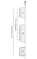
- FIG. 1 is a diagram showing an example of component carrier settings in the present embodiment.
- one LTE cell and two NR cells are set.
- One LTE cell is set as a primary cell.
- the two NR cells are set as a primary secondary cell and a secondary cell, respectively.
- the two NR cells are integrated by carrier aggregation.
- the LTE cell and the NR cell are integrated by dual connectivity. Note that the LTE cell and the NR cell may be integrated by carrier aggregation.
- the NR since the NR can be assisted by the LTE cell that is the primary cell, the NR may not support some functions such as a function for performing stand-alone communication.
- the function for stand-alone communication includes a function necessary for initial connection.
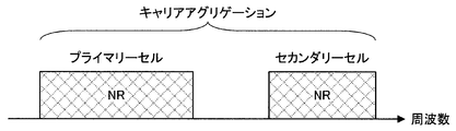
- FIG. 2 is a diagram illustrating an example of component carrier settings in the present embodiment.
- two NR cells are set.
- the two NR cells are set as a primary cell and a secondary cell, respectively, and are integrated by carrier aggregation.
- the support of the LTE cell becomes unnecessary by supporting the function for the NR cell to perform stand-alone communication.
- the two NR cells may be integrated by dual connectivity.
- Radio frame configuration in this embodiment> a radio frame composed of 10 ms (milliseconds) is defined. Each radio frame is composed of two half frames. The time interval of the half frame is 5 ms. Each half frame is composed of five subframes. The subframe time interval is 1 ms and is defined by two consecutive slots. The slot time interval is 0.5 ms. The i-th subframe in the radio frame is composed of a (2 ⁇ i) th slot and a (2 ⁇ i + 1) th slot. That is, 10 subframes are defined in each radio frame.
- the subframe includes a downlink subframe, an uplink subframe, a special subframe, a sidelink subframe, and the like.
- the downlink subframe is a subframe reserved for downlink transmission.
- An uplink subframe is a subframe reserved for uplink transmission.
- the special subframe is composed of three fields. The three fields include DwPTS (Downlink Pilot Time Slot), GP (Guard Period), and UpPTS (Uplink Pilot Time Slot). The total length of DwPTS, GP, and UpPTS is 1 ms.
- DwPTS is a field reserved for downlink transmission.
- UpPTS is a field reserved for uplink transmission.
- GP is a field in which downlink transmission and uplink transmission are not performed. Note that the special subframe may be configured only by DwPTS and GP, or may be configured only by GP and UpPTS.
- the special subframe is arranged between the downlink subframe and the uplink subframe in TDD, and is used for switching from the downlink subframe to the uplink subframe.
- the side link subframe is a subframe reserved or set for side link communication.
- the side link is used for proximity direct communication and proximity direct detection between terminal devices.
- a single radio frame includes a downlink subframe, an uplink subframe, a special subframe, and / or a sidelink subframe. Also, a single radio frame may be composed of only downlink subframes, uplink subframes, special subframes, or sidelink subframes.
- the radio frame configuration is defined by the frame configuration type.
- Frame configuration type 1 is applicable only to FDD.
- Frame configuration type 2 is applicable only to TDD.
- Frame configuration type 3 is applicable only to operation of LAA (Licensed Assisted Access) secondary cells.
- each of the 10 subframes in one radio frame corresponds to one of a downlink subframe, an uplink subframe, and a special subframe.
- Subframe 0, subframe 5 and DwPTS are always reserved for downlink transmission.
- the subframe immediately following UpPTS and its special subframe is always reserved for uplink transmission.
- the terminal device 2 can handle a subframe in which no PDSCH or detection signal is transmitted as an empty subframe.
- the terminal apparatus 2 assumes that no signal and / or channel exists in the subframe unless a predetermined signal, channel and / or downlink transmission is detected in the subframe.
- Downlink transmission is dedicated in one or more consecutive subframes.
- the first subframe of the downlink transmission may start from anywhere within that subframe.
- the last subframe of the downlink transmission may be either completely occupied or dedicated at a time interval defined by DwPTS.
- 10 subframes in one radio frame may be reserved for uplink transmission. Further, each of the 10 subframes in one radio frame may correspond to any of a downlink subframe, an uplink subframe, a special subframe, and a sidelink subframe.
- the base station apparatus 1 may transmit the downlink physical channel and the downlink physical signal in DwPTS of the special subframe.
- the base station apparatus 1 can restrict PBCH transmission in DwPTS of the special subframe.
- the terminal device 2 may transmit an uplink physical channel and an uplink physical signal in the UpPTS of the special subframe.
- the terminal device 2 can restrict transmission of some uplink physical channels and uplink physical signals in the UpPTS of the special subframe.
- TTI Transmission In the LTE, 1 ms (1 subframe) is defined as 1 TTI.
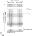
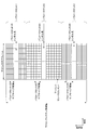
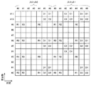
- FIG. 3 is a diagram illustrating an example of an LTE downlink subframe in the present embodiment.
- the diagram shown in FIG. 3 is also referred to as an LTE downlink resource grid.
- the base station apparatus 1 can transmit an LTE downlink physical channel and / or an LTE downlink physical signal in a downlink subframe to the terminal apparatus 2.
- the terminal apparatus 2 can receive an LTE downlink physical channel and / or an LTE downlink physical signal in the downlink subframe from the base station apparatus 1.
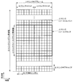
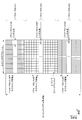
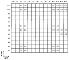
- FIG. 4 is a diagram illustrating an example of an LTE uplink subframe in the present embodiment.
- the diagram shown in FIG. 4 is also referred to as an LTE uplink resource grid.
- the terminal device 2 can transmit an LTE uplink physical channel and / or an LTE uplink physical signal in an uplink subframe to the base station device 1.
- the base station apparatus 1 can receive an LTE uplink physical channel and / or an LTE uplink physical signal in an uplink subframe from the terminal apparatus 2.
- LTE physical resources can be defined as follows.
- One slot is defined by a plurality of symbols.
- the physical signal or physical channel transmitted in each of the slots is represented by a resource grid.
- the resource grid is defined by a plurality of subcarriers in the frequency direction and a plurality of OFDM symbols in the time direction.
- the resource grid is defined by a plurality of subcarriers in the frequency direction and a plurality of SC-FDMA symbols in the time direction.
- the number of subcarriers or resource blocks may be determined depending on the cell bandwidth.
- the number of symbols in one slot is determined by the CP (Cyclic Prefix) type.
- the CP type is a normal CP or an extended CP.
- the number of OFDM symbols or SC-FDMA symbols constituting one slot is seven.
- the number of OFDM symbols or SC-FDMA symbols constituting one slot is six.
- Each element in the resource grid is called a resource element.
- the resource element is identified using a subcarrier index (number) and a symbol index (number).
- the OFDM symbol or SC-FDMA symbol is also simply referred to as a symbol.
- the resource block is used for mapping a certain physical channel (such as PDSCH or PUSCH) to a resource element.
- the resource block includes a virtual resource block and a physical resource block.
- a certain physical channel is mapped to a virtual resource block.
- a virtual resource block is mapped to a physical resource block.
- One physical resource block is defined by a predetermined number of consecutive symbols in the time domain.
- One physical resource block is defined from a predetermined number of consecutive subcarriers in the frequency domain. The number of symbols and the number of subcarriers in one physical resource block are determined based on the type of CP in the cell, the subcarrier spacing, and / or parameters set by higher layers.
- one physical resource block is composed of (7 ⁇ 12) resource elements. Physical resource blocks are numbered from 0 in the frequency domain. Further, two resource blocks in one subframe corresponding to the same physical resource block number are defined as physical resource block pairs (PRB pair, RB pair).
- the predetermined parameter is a parameter (physical parameter) related to the transmission signal.
- Parameters related to the transmission signal include CP length, subcarrier interval, number of symbols in one subframe (predetermined time length), number of subcarriers in one resource block (predetermined frequency band), multiple access scheme, and signal Includes waveforms.
- the downlink signal and the uplink signal are generated using one predetermined parameter in each predetermined time length (for example, subframe).
- the terminal apparatus 2 generates a downlink signal transmitted from the base station apparatus 1 and an uplink signal transmitted to the base station apparatus 1 with one predetermined parameter for each predetermined time length.
- the base station apparatus 1 generates a downlink signal transmitted to the terminal apparatus 2 and an uplink signal transmitted from the terminal apparatus 2 with one predetermined parameter for each predetermined time length.
- ⁇ Frame structure of NR in this embodiment> In each of the NR cells, one or more predetermined parameters are used in a certain predetermined time length (for example, subframe). That is, in the NR cell, the downlink signal and the uplink signal are each generated with one or more predetermined parameters in a predetermined time length.
- the terminal apparatus 2 generates a downlink signal transmitted from the base station apparatus 1 and an uplink signal transmitted to the base station apparatus 1 with one or more predetermined parameters in a predetermined time length.
- the base station apparatus 1 generates a downlink signal to be transmitted to the terminal apparatus 2 and an uplink signal to be transmitted from the terminal apparatus 2 with one or more predetermined parameters for each predetermined time length.
- the predetermined method is FDM (Frequency Division Multiplexing (TDM), Time Division Multiplexing (TDM), Code Division Multiplexing (CDM), and / or Spatial Division Multiplexing (SDM) are included.
- FDM Frequency Division Multiplexing
- TDM Time Division Multiplexing
- CDM Code Division Multiplexing
- SDM Spatial Division Multiplexing
- a plurality of types of combinations of predetermined parameters set in the NR cell can be specified in advance as a parameter set.
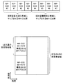
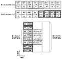
- FIG. 5 is a diagram illustrating an example of a parameter set relating to a transmission signal in the NR cell.
- the parameters related to the transmission signal included in the parameter set are subcarrier spacing, number of subcarriers per resource block in the NR cell, number of symbols per subframe, and CP length type.
- the CP length type is a CP length type used in the NR cell.
- CP length type 1 corresponds to a normal CP in LTE
- CP length type 2 corresponds to an extended CP in LTE.
- Parameter sets related to transmission signals in the NR cell can be individually defined for the downlink and uplink. Also, parameter sets related to transmission signals in the NR cell can be set independently for the downlink and uplink.
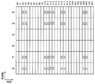
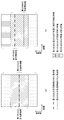
- FIG. 6 is a diagram illustrating an example of an NR downlink subframe in the present embodiment.
- a signal generated using the parameter set 1, the parameter set 0, and the parameter set 2 is FDM in the cell (system bandwidth).
- the diagram shown in FIG. 6 is also referred to as the NR downlink resource grid.
- the base station apparatus 1 can transmit an NR downlink physical channel and / or an NR downlink physical signal in a downlink subframe to the terminal apparatus 2.
- the terminal apparatus 2 can receive the NR downlink physical channel and / or the NR downlink physical signal in the downlink subframe from the base station apparatus 1.
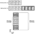
- FIG. 7 is a diagram illustrating an example of an uplink subframe of NR in the present embodiment.
- a signal generated using parameter set 1, parameter set 0, and parameter set 2 is FDM in a cell (system bandwidth).
- the diagram shown in FIG. 6 is also referred to as the NR uplink resource grid.
- the base station apparatus 1 can transmit an NR uplink physical channel and / or an NR uplink physical signal in an uplink subframe to the terminal apparatus 2.
- the terminal apparatus 2 can receive the NR uplink physical channel and / or the NR uplink physical signal in the uplink subframe from the base station apparatus 1.
- An antenna port is defined so that a propagation channel carrying one symbol can be inferred from a propagation channel carrying another symbol at the same antenna port. For example, it can be assumed that different physical resources in the same antenna port are transmitted on the same propagation channel. In other words, a symbol at a certain antenna port can be demodulated by estimating a propagation channel using a reference signal at that antenna port. There is one resource grid per antenna port.
- An antenna port is defined by a reference signal. Each reference signal can define a plurality of antenna ports.
- the antenna port is specified or identified by the antenna port number.
- antenna ports 0 to 3 are antenna ports to which CRS (Cell-specific Reference Signal) is transmitted. That is, the PDSCH transmitted through the antenna ports 0 to 3 can be demodulated by the CRS corresponding to the antenna ports 0 to 3.
- CRS Cell-specific Reference Signal
- the two antenna ports satisfy a predetermined condition, they can be expressed as quasi-identical positions (QCL: Quasi co-location).
- the predetermined condition is that the wide-area characteristics of a propagation channel carrying a symbol at one antenna port can be inferred from the propagation channel carrying a symbol at another antenna port.
- Global characteristics include delay dispersion, Doppler spread, Doppler shift, average gain and / or average delay.
- the antenna port number may be defined differently for each RAT, or may be defined in common between RATs.
- antenna ports 0 to 3 in LTE are antenna ports through which CRS is transmitted.
- the antenna ports 0 to 3 can be antenna ports through which CRS similar to LTE is transmitted.
- an antenna port for transmitting a CRS similar to LTE can have an antenna port number different from antenna ports 0 to 3.
- the predetermined antenna port number can be applied to LTE and / or NR.
- the physical channel includes a downlink physical channel, an uplink physical channel, and a side link physical channel.
- the physical signal includes a downlink physical signal, an uplink physical signal, and a side link physical signal.
- Physical channels and physical signals in LTE are also referred to as LTE physical channels and LTE physical signals, respectively.
- the physical channel and physical signal in NR are also referred to as NR physical channel and NR physical signal, respectively.
- the LTE physical channel and the NR physical channel can be defined as different physical channels.
- the LTE physical signal and the NR physical signal can be defined as different physical signals.
- the LTE physical channel and the NR physical channel are also simply referred to as physical channels, and the LTE physical signal and the NR physical signal are also simply referred to as physical signals. That is, the description for the physical channel can be applied to both the LTE physical channel and the NR physical channel. The description for the physical signal can be applied to both the LTE physical signal and the NR physical signal.
- NR physical channel and NR physical signal in this embodiment The description for the physical channel and the physical signal in LTE can be applied to the NR physical channel and the NR physical signal, respectively.
- the NR physical channel and the NR physical signal are referred to as follows.
- NR downlink physical channels include NR-PBCH, NR-PCFICH, NR-PHICH, NR-PDCCH, NR-EPDCCH, NR-MPDCCH, NR-R-PDCCH, NR-PDSCH, NR-PMCH, and the like.
- NR downlink physical signals include NR-SS, NR-DL-RS, NR-DS, and the like.
- NR-SS includes NR-PSS, NR-SSS, and the like.
- the NR-RS includes NR-CRS, NR-PDSCH-DMRS, NR-EPDCCH-DMRS, NR-PRS, NR-CSI-RS, NR-TRS, and the like.
- NR uplink physical channel includes NR-PUSCH, NR-PUCCH, NR-PRACH, and the like.
- NR uplink physical signal includes NR-UL-RS.
- NR-UL-RS includes NR-UL-DMRS and NR-SRS.
- NR side link physical channels include NR-PSBCH, NR-PSCCH, NR-PSDCH, NR-PSSCH, and the like.
- the PBCH is used to broadcast an MIB (Master Information Block) that is broadcast information unique to the serving cell of the base station apparatus 1.
- MIB Master Information Block
- PBCH is transmitted only in subframe 0 in the radio frame.
- the MIB can be updated at 40 ms intervals.
- the PBCH is repeatedly transmitted at a period of 10 ms. Specifically, an initial MIB transmission is performed in subframe 0 in a radio frame that satisfies the condition that the remainder of SFN (System Frame Number) divided by 4 is 0, and in subframe 0 in all other radio frames. MIB retransmission is performed.
- SFN is a radio frame number (system frame number).
- MIB is system information. For example, the MIB includes information indicating SFN.
- PCFICH is used to transmit information regarding the number of OFDM symbols used for transmission of PDCCH. A region indicated by PCFICH is also referred to as a PDCCH region. Information transmitted by PCFICH is CFI (Control Also called Format Indicator
- the PHICH transmits HARQ-ACK (HARQ indicator, HARQ feedback, response information) indicating ACK (ACKnowledgement) or NACK (Negative ACKnowledgement) for the uplink data (Uplink Shared Channel: UL-SCH) received by the base station apparatus 1. Used to do. For example, when the terminal apparatus 2 receives HARQ-ACK indicating ACK, the corresponding uplink data is not retransmitted. For example, when the terminal apparatus 2 receives HARQ-ACK indicating NACK, the terminal apparatus 2 retransmits corresponding uplink data in a predetermined uplink subframe.
- a certain PHICH transmits a HARQ-ACK for certain uplink data.
- the base station apparatus 1 transmits each HARQ-ACK for a plurality of uplink data included in the same PUSCH using a plurality of PHICHs.
- PDCCH and EPDCCH are used to transmit downlink control information (DCI). Mapping of information bits of downlink control information is defined as a DCI format.
- the downlink control information includes a downlink grant (downlink grant) and an uplink grant (uplink grant).
- the downlink grant is also referred to as a downlink assignment or a downlink allocation.
- the PDCCH is transmitted by a set of one or more continuous CCEs (Control Channel Elements).
- the CCE is composed of nine REGs (Resource Element Groups).
- the REG is composed of four resource elements.
- EPDCCH is transmitted by a set of one or more continuous ECCEs (Enhanced Control Channel Elements).
- ECCE is composed of multiple EREGs (Enhanced Resource Element Group).
- the downlink grant is used for scheduling the PDSCH in a certain cell.
- the downlink grant is used for scheduling the PDSCH in the same subframe as the subframe in which the downlink grant is transmitted.
- the uplink grant is used for scheduling the PUSCH in a certain cell.
- the uplink grant is used for scheduling a single PUSCH in a subframe that is four or more times after the subframe in which the uplink grant is transmitted.
- the CRC parity bit is added to DCI.
- the CRC parity bit is scrambled by RNTI (Radio Network Temporary Identifier).
- the RNTI is an identifier that can be defined or set according to the purpose of the DCI.
- the RNTI is set as an identifier preliminarily specified in the specification, an identifier set as information specific to a cell, an identifier set as information specific to the terminal device 2, or information specific to a group belonging to the terminal device 2.
- Identifier For example, in monitoring PDCCH or EPDCCH, the terminal device 2 descrambles a CRC parity bit added to DCI with a predetermined RNTI and identifies whether the CRC is correct. If the CRC is correct, it can be seen that the DCI is the DCI for the terminal device 2.
- PDSCH is used to transmit downlink data (Downlink Shared Channel: DL-SCH).
- DL-SCH Downlink Shared Channel
- the PDSCH is also used for transmitting higher layer control information.
- PMCH is used to transmit multicast data (Multicast Channel: MCH).
- a plurality of PDCCHs may be frequency, time and / or spatially multiplexed.
- a plurality of EPDCCHs may be frequency, time and / or spatially multiplexed.
- a plurality of PDSCHs may be frequency, time and / or spatially multiplexed.
- PDCCH, PDSCH and / or EPDCCH may be frequency, time and / or spatially multiplexed.
- the synchronization signal is used for the terminal apparatus 2 to synchronize the downlink frequency domain and / or time domain.
- the synchronization signal is PSS (Primary Synchronization Signal) and SSS (Secondary Synchronization Signal) are included.
- the synchronization signal is arranged in a predetermined subframe in the radio frame. For example, in the TDD scheme, the synchronization signal is arranged in subframes 0, 1, 5, and 6 in the radio frame. In the FDD scheme, the synchronization signal is arranged in subframes 0 and 5 in the radio frame.
- PSS may be used for coarse frame / symbol timing synchronization (time domain synchronization) and cell identification group identification.
- the SSS may be used for more accurate frame timing synchronization, cell identification, and CP length detection. That is, frame timing synchronization and cell identification can be performed by using PSS and SSS.
- the downlink reference signal is transmitted from the terminal apparatus 2 to downlink physical channel propagation path estimation, propagation path correction, and downlink CSI (Channel (State Information, channel state information) and / or measurement of positioning of the terminal device 2 is used.
- downlink CSI Channel (State Information, channel state information) and / or measurement of positioning of the terminal device 2 is used.
- CRS is transmitted in the entire bandwidth of the subframe.
- CRS is used to receive (demodulate) PBCH, PDCCH, PHICH, PCFICH, and PDSCH.
- the CRS may be used for the terminal device 2 to calculate downlink channel state information.
- PBCH, PDCCH, PHICH, and PCFICH are transmitted by an antenna port used for transmission of CRS.
- CRS supports 1, 2 or 4 antenna port configurations.
- CRS is transmitted on one or more of antenna ports 0-3.
- URS related to PDSCH is transmitted in a subframe and a band used for transmission of PDSCH related to URS. URS is used to demodulate the PDSCH with which the URS is associated. The URS associated with the PDSCH is transmitted on one or more of the antenna ports 5, 7-14.
- the PDSCH is transmitted by an antenna port used for transmission of CRS or URS based on the transmission mode and the DCI format.
- the DCI format 1A is used for scheduling of PDSCH transmitted through an antenna port used for CRS transmission.
- the DCI format 2D is used for scheduling of the PDSCH transmitted through the antenna port used for URS transmission.
- DMRS related to EPDCCH is transmitted in subframes and bands used for transmission of EPDCCH related to DMRS.
- DMRS is used to demodulate the EPDCCH with which DMRS is associated.
- the EPDCCH is transmitted through an antenna port used for DMRS transmission.
- the DMRS associated with the EPDCCH is transmitted on one or more of the antenna ports 107-114.
- CSI-RS is transmitted in the set subframe. Resources for transmitting the CSI-RS are set by the base station apparatus 1.
- the CSI-RS is used for the terminal apparatus 2 to calculate downlink channel state information.
- the terminal device 2 performs signal measurement (channel measurement) using CSI-RS.
- CSI-RS supports configuration of some or all antenna ports of 1, 2, 4, 8, 12, 16, 24 and 32.
- CSI-RS is transmitted on one or more of antenna ports 15-46.
- the supported antenna port may be determined based on the terminal device capability of the terminal device 2, the setting of the RRC parameter, and / or the set transmission mode.
- ZP CSI-RS resources are set by higher layers. ZP CSI-RS resources may be transmitted with zero output power. That is, no ZP CSI-RS resource need be transmitted. PDSCH and EPDCCH are not transmitted in the resource set by ZP CSI-RS.
- ZP CSI-RS resources are used by neighboring cells to transmit NZP CSI-RS.
- ZP CSI-RS resources are used to measure CSI-IM.
- the ZP CSI-RS resource is a resource to which a predetermined channel such as PDSCH is not transmitted. In other words, a predetermined channel is mapped by excluding ZP CSI-RS resources (rate matching and puncturing).
- the PUCCH is a physical channel used for transmitting uplink control information (UPCI).
- the uplink control information includes downlink channel state information (CSI), scheduling request (SR) indicating a request for PUSCH resources, downlink data (Transport block: TB, Downlink-Shared Channel: DL).
- -SCH downlink data for HARQ-ACK.
- HARQ-ACK is also referred to as ACK / NACK, HARQ feedback, or response information.
- HARQ-ACK for downlink data indicates ACK, NACK, or DTX.
- PUSCH is a physical channel used for transmitting uplink data (Uplink-Shared Channel: UL-SCH).
- the PUSCH may also be used to transmit HARQ-ACK and / or channel state information along with uplink data. Also, the PUSCH may be used to transmit only channel state information or only HARQ-ACK and channel state information.
- PRACH is a physical channel used to transmit a random access preamble.
- the PRACH can be used for the terminal device 2 to synchronize with the base station device 1 in the time domain.
- PRACH is an initial connection establishment procedure (processing), a handover procedure, a connection re-establishment procedure, synchronization for uplink transmission (timing adjustment), and / or PUSCH resource request. Also used to indicate
- a plurality of PUCCHs are frequency, time, space and / or code multiplexed.
- a plurality of PUSCHs may be frequency, time, space and / or code multiplexed.
- PUCCH and PUSCH may be frequency, time, space and / or code multiplexed.
- the PRACH may be arranged over a single subframe or two subframes. A plurality of PRACHs may be code-multiplexed.
- a resource element group is used to define a mapping between resource elements and control channels.
- REG is used for mapping of PDCCH, PHICH, or PCFICH.
- the REG is composed of four consecutive resource elements that are not used for CRS in the same OFDM symbol and in the same resource block.
- the REG is configured from the first OFDM symbol to the fourth OFDM symbol in the first slot in a certain subframe.
- Extended resource element group is used to define the mapping between resource elements and extended control channels.
- EREG is used for EPDCCH mapping.
- One resource block pair is composed of 16 EREGs. Each EREG is assigned a number from 0 to 15 for each resource block pair.
- Each EREG is composed of nine resource elements excluding resource elements used for DM-RS associated with EPDCCH in one resource block pair.
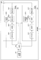
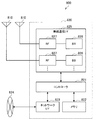
- FIG. 8 is a schematic block diagram illustrating the configuration of the base station device 1 of the present embodiment.
- the base station apparatus 1 includes an upper layer processing unit 101, a control unit 103, a receiving unit 105, a transmitting unit 107, and a transmission / reception antenna 109.
- the reception unit 105 includes a decoding unit 1051, a demodulation unit 1053, a demultiplexing unit 1055, a radio reception unit 1057, and a channel measurement unit 1059.
- the transmission unit 107 includes an encoding unit 1071, a modulation unit 1073, a multiplexing unit 1075, a radio transmission unit 1077, and a downlink reference signal generation unit 1079.
- the base station apparatus 1 can support one or more RATs.
- Part or all of the units included in the base station apparatus 1 shown in FIG. 8 can be individually configured according to the RAT.
- the reception unit 105 and the transmission unit 107 are individually configured with LTE and NR.
- a part or all of each unit included in the base station apparatus 1 shown in FIG. 8 can be individually configured according to a parameter set related to a transmission signal.
- the radio reception unit 1057 and the radio transmission unit 1077 can be individually configured according to a parameter set regarding a transmission signal.
- the upper layer processing unit 101 includes a medium access control (MAC) layer, a packet data integration protocol (Packet Data Convergence Protocol: PDCP) layer, a radio link control (Radio Link Control: RLC) layer, a radio resource control (Radio). Process Resource Control: RRC) layer. Further, the upper layer processing unit 101 generates control information for controlling the reception unit 105 and the transmission unit 107 and outputs the control information to the control unit 103.
- MAC medium access control
- PDCP Packet Data Convergence Protocol
- RLC Radio Link Control
- Radio Radio
- RRC Radio Resource Control
- the control unit 103 controls the reception unit 105 and the transmission unit 107 based on the control information from the higher layer processing unit 101.
- the control unit 103 generates control information for the upper layer processing unit 101 and outputs the control information to the upper layer processing unit 101.
- the control unit 103 inputs the decoded signal from the decoding unit 1051 and the channel estimation result from the channel measurement unit 1059.
- the control unit 103 outputs a signal to be encoded to the encoding unit 1071.
- the control unit 103 is used to control all or part of the base station apparatus 1.
- the upper layer processing unit 101 performs processing and management related to RAT control, radio resource control, subframe setting, scheduling control, and / or CSI report control.
- the processing and management in the upper layer processing unit 101 is performed for each terminal device or for the terminal devices connected to the base station device.
- the processing and management in the upper layer processing unit 101 may be performed only by the upper layer processing unit 101, or may be acquired from an upper node or another base station device. Further, the processing and management in the upper layer processing unit 101 may be performed individually according to the RAT. For example, the upper layer processing unit 101 individually performs processing and management in LTE and processing and management in NR.
- management related to RAT is performed.
- management related to LTE and / or management related to NR is performed.
- Management regarding NR includes setting and processing of parameter sets regarding transmission signals in the NR cell.
- radio resource control in the upper layer processing unit 101, generation and / or management of downlink data (transport block), system information, RRC message (RRC parameter), and / or MAC control element (CE) is performed. Done.
- subframe setting in the upper layer processing unit 101 subframe setting, subframe pattern setting, uplink-downlink setting, uplink reference UL-DL setting, and / or downlink reference UL-DL setting are managed. Is called.
- the subframe setting in higher layer processing section 101 is also referred to as base station subframe setting.
- the subframe setting in the higher layer processing unit 101 can be determined based on the uplink traffic volume and the downlink traffic volume. Further, the subframe setting in the upper layer processing unit 101 can be determined based on the scheduling result of the scheduling control in the upper layer processing unit 101.
- the frequency and subframe to which a physical channel is allocated, the physical channel's A coding rate, a modulation scheme, transmission power, and the like are determined.
- the control unit 103 generates control information (DCI format) based on the scheduling result of scheduling control in the upper layer processing unit 101.
- the CSI report of the terminal device 2 is controlled.
- the setting related to the CSI reference resource to be assumed for calculating the CSI in the terminal device 2 is controlled.
- the receiving unit 105 receives a signal transmitted from the terminal device 2 via the transmission / reception antenna 109 in accordance with control from the control unit 103, further performs reception processing such as separation, demodulation, and decoding, and receives the received information. Output to the control unit 103. Note that the reception process in the reception unit 105 is performed based on a setting specified in advance or a setting notified from the base station apparatus 1 to the terminal apparatus 2.
- the radio reception unit 1057 converts the uplink signal received via the transmission / reception antenna 109 into an intermediate frequency (down-conversion), removes unnecessary frequency components, and appropriately maintains the signal level. Control of amplification level, quadrature demodulation based on in-phase and quadrature components of received signal, conversion from analog signal to digital signal, removal of guard interval (GI), and / or fast Fourier transform (Fast Fourier transform) Extract frequency domain signals by Transform: FFT).
- GI guard interval
- FFT fast Fourier transform
- the demultiplexing unit 1055 separates an uplink channel such as PUCCH or PUSCH and / or an uplink reference signal from the signal input from the radio reception unit 1057.
- the demultiplexing unit 1055 outputs the uplink reference signal to the channel measurement unit 1059.
- the demultiplexing unit 1055 performs channel compensation for the uplink channel from the channel estimation value input from the channel measurement unit 1059.
- the demodulation unit 1053 receives a received signal using a modulation scheme such as BPSK (Binary Phase Shift Keying), QPSK (Quadrature Phase Shift Keying), 16QAM (Quadrature Amplitude Modulation), 64QAM, or 256QAM for the modulation symbol of the uplink channel. Is demodulated.
- Demodulation section 1053 separates and demodulates the MIMO multiplexed uplink channel.
- the decoding unit 1051 performs a decoding process on the demodulated uplink channel encoded bits.
- the decoded uplink data and / or uplink control information is output to the control unit 103.
- Decoding section 1051 performs decoding processing for each transport block for PUSCH.
- the channel measurement unit 1059 measures the propagation path estimation value and / or channel quality from the uplink reference signal input from the demultiplexing unit 1055, and outputs it to the demultiplexing unit 1055 and / or the control unit 103.
- the channel measurement unit 1059 measures a channel estimation value for channel compensation for PUCCH or PUSCH using UL-DMRS, and measures the channel quality in the uplink using SRS.
- the transmission unit 107 performs transmission processing such as encoding, modulation, and multiplexing on the downlink control information and the downlink data input from the higher layer processing unit 101 according to the control from the control unit 103. For example, the transmission unit 107 generates and multiplexes PHICH, PDCCH, EPDCCH, PDSCH, and a downlink reference signal, and generates a transmission signal. Note that the transmission processing in the transmission unit 107 is based on settings specified in advance, settings notified from the base station apparatus 1 to the terminal apparatus 2, or settings notified via the PDCCH or EPDCCH transmitted in the same subframe. Done.
- the encoding unit 1071 performs HARQ indicator (HARQ-ACK), downlink control information, and downlink data input from the control unit 103 with predetermined encoding such as block encoding, convolutional encoding, and turbo encoding. Encoding is performed using a method.
- the modulation unit 1073 modulates the coded bits input from the coding unit 1071 with a predetermined modulation method such as BPSK, QPSK, 16QAM, 64QAM, 256QAM.
- the downlink reference signal generation unit 1079 generates a downlink reference signal based on a physical cell identifier (PCI), an RRC parameter set in the terminal device 2, and the like.
- Multiplexer 1075 multiplexes the modulation symbols and downlink reference signals for each channel and arranges them in a predetermined resource element.
- the radio transmission unit 1077 converts the signal from the multiplexing unit 1075 into a time-domain signal by inverse fast Fourier transform (IFFT), adds a guard interval, generates a baseband digital signal, Performs conversion to analog signal, quadrature modulation, conversion from intermediate frequency signal to high frequency signal (up-convert), removal of excess frequency components, power amplification, etc. to generate a transmission signal .
- IFFT inverse fast Fourier transform
- the transmission signal output from the wireless transmission unit 1077 is transmitted from the transmission / reception antenna 109.
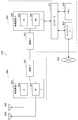
- FIG. 9 is a schematic block diagram showing the configuration of the terminal device 2 of the present embodiment.
- the terminal device 2 includes an upper layer processing unit 201, a control unit 203, a reception unit 205, a transmission unit 207, and a transmission / reception antenna 209.
- the reception unit 205 includes a decoding unit 2051, a demodulation unit 2053, a demultiplexing unit 2055, a radio reception unit 2057, and a channel measurement unit 2059.
- the transmission unit 207 includes an encoding unit 2071, a modulation unit 2073, a multiplexing unit 2075, a radio transmission unit 2077, and an uplink reference signal generation unit 2079.
- the terminal device 2 can support one or more RATs. Some or all of the units included in the terminal device 2 illustrated in FIG. 9 can be individually configured according to the RAT.
- the reception unit 205 and the transmission unit 207 are individually configured with LTE and NR.
- the NR cell some or all of the units included in the terminal device 2 shown in FIG. 9 can be individually configured according to the parameter set related to the transmission signal.
- the radio reception unit 2057 and the radio transmission unit 2077 can be individually configured according to a parameter set related to a transmission signal.
- the higher layer processing unit 201 outputs the uplink data (transport block) to the control unit 203.
- the upper layer processing unit 201 includes a medium access control (MAC) layer, a packet data integration protocol (Packet Data Convergence Protocol: PDCP) layer, a radio link control (Radio Link Control: RLC) layer, a radio resource control (Radio). Process Resource Control: RRC) layer. Further, the upper layer processing unit 201 generates control information for controlling the reception unit 205 and the transmission unit 207 and outputs the control information to the control unit 203.
- MAC medium access control
- PDCP Packet Data Convergence Protocol
- RLC Radio Link Control
- RRC Radio Resource Control
- the control unit 203 controls the reception unit 205 and the transmission unit 207 based on the control information from the higher layer processing unit 201.
- the control unit 203 generates control information for the upper layer processing unit 201 and outputs the control information to the upper layer processing unit 201.
- the control unit 203 inputs the decoded signal from the decoding unit 2051 and the channel estimation result from the channel measurement unit 2059.
- the control unit 203 outputs a signal to be encoded to the encoding unit 2071. Further, the control unit 203 may be used to control all or part of the terminal device 2.
- the upper layer processing unit 201 performs processing and management related to RAT control, radio resource control, subframe setting, scheduling control, and / or CSI report control.
- the processing and management in the upper layer processing unit 201 are performed based on settings specified in advance and / or settings based on control information set or notified from the base station apparatus 1.
- the control information from the base station apparatus 1 includes an RRC parameter, a MAC control element, or DCI.
- the processing and management in the upper layer processing unit 201 may be performed individually according to the RAT.
- the upper layer processing unit 201 individually performs processing and management in LTE and processing and management in NR.
- management related to RAT is performed.
- management related to LTE and / or management related to NR is performed.
- Management regarding NR includes setting and processing of parameter sets regarding transmission signals in the NR cell.
- radio resource control in the higher layer processing unit 201 management of setting information in the own apparatus is performed.
- radio resource control in the upper layer processing unit 201 generation and / or management of uplink data (transport block), system information, RRC message (RRC parameter), and / or MAC control element (CE) is performed. Done.
- the subframe setting in the upper layer processing unit 201 the subframe setting in the base station apparatus 1 and / or a base station apparatus different from the base station apparatus 1 is managed.
- the subframe configuration includes uplink or downlink configuration, subframe pattern configuration, uplink-downlink configuration, uplink reference UL-DL configuration, and / or downlink reference UL-DL configuration for the subframe.
- the subframe setting in the higher layer processing unit 201 is also referred to as terminal subframe setting.
- control information for performing control related to scheduling for the reception unit 205 and the transmission unit 207 is generated based on DCI (scheduling information) from the base station apparatus 1.
- control related to CSI reporting to the base station apparatus 1 is performed.
- the channel measurement unit 2059 controls settings related to CSI reference resources that are assumed to calculate CSI.
- resources (timing) used for reporting CSI are controlled based on DCI and / or RRC parameters.
- the receiving unit 205 receives the signal transmitted from the base station apparatus 1 via the transmission / reception antenna 209 according to the control from the control unit 203, and further performs reception processing such as separation, demodulation, decoding, and the like. Is output to the control unit 203. Note that the reception process in the reception unit 205 is performed based on a predetermined setting or a notification or setting from the base station apparatus 1.
- the radio reception unit 2057 converts the uplink signal received via the transmission / reception antenna 209 to an intermediate frequency (down-conversion), removes unnecessary frequency components, and appropriately maintains the signal level. Control of amplification level, quadrature demodulation based on in-phase and quadrature components of received signal, conversion from analog signal to digital signal, removal of guard interval (GI), and / or fast Fourier transform (Fast Fourier transform) Extracts frequency domain signals using Transform (FFT).
- FFT Fast Fourier transform
- the demultiplexing unit 2055 separates a downlink channel such as PHICH, PDCCH, EPDCCH, or PDSCH, a downlink synchronization signal, and / or a downlink reference signal from the signal input from the radio reception unit 2057.
- the demultiplexing unit 2055 outputs the downlink reference signal to the channel measurement unit 2059.
- the demultiplexing unit 2055 performs channel compensation for the downlink channel from the channel estimation value input from the channel measurement unit 2059.
- the demodulator 2053 demodulates the received signal using a modulation scheme such as BPSK, QPSK, 16QAM, 64QAM, 256QAM, etc., with respect to the downlink channel modulation symbols.
- the demodulator 2053 separates and demodulates the MIMO multiplexed downlink channel.
- the decoding unit 2051 performs a decoding process on the demodulated downlink channel encoded bits.
- the decoded downlink data and / or downlink control information is output to the control unit 203.
- the decoding unit 2051 performs a decoding process for each transport block on the PDSCH.
- the channel measurement unit 2059 measures the estimated value of the propagation path and / or the channel quality from the downlink reference signal input from the demultiplexing unit 2055 and outputs it to the demultiplexing unit 2055 and / or the control unit 203.
- the downlink reference signal used for measurement by the channel measurement unit 2059 may be determined based on at least the transmission mode set by the RRC parameter and / or other RRC parameters.
- DL-DMRS measures an estimated value of a propagation path for performing propagation path compensation for PDSCH or EPDCCH.
- CRS measures a channel estimation value for performing channel compensation for PDCCH or PDSCH and / or a channel in the downlink for reporting CSI.
- CSI-RS measures the channel in the downlink for reporting CSI.
- the channel measurement unit 2059 calculates RSRP (Reference Signal Received Power) and / or RSRQ (Reference Signal Received Quality) based on the CRS, CSI-RS, or detection signal, and outputs it to the upper layer processing unit
- the transmission unit 207 performs transmission processing such as encoding, modulation, and multiplexing on the uplink control information and the uplink data input from the higher layer processing unit 201 according to the control from the control unit 203. For example, the transmission unit 207 generates and multiplexes an uplink channel such as PUSCH or PUCCH and / or an uplink reference signal, and generates a transmission signal. Note that the transmission processing in the transmission unit 207 is performed based on settings specified in advance or settings or notifications from the base station apparatus 1.
- the encoding unit 2071 encodes the HARQ indicator (HARQ-ACK), the uplink control information, and the uplink data input from the control unit 203 with predetermined encoding such as block encoding, convolutional encoding, and turbo encoding. Encoding is performed using a method.
- the modulation unit 2073 modulates the coded bits input from the coding unit 2071 using a predetermined modulation method such as BPSK, QPSK, 16QAM, 64QAM, or 256QAM.
- the uplink reference signal generation unit 2079 generates an uplink reference signal based on the RRC parameter set in the terminal device 2 and the like.
- Multiplexing section 2075 multiplexes the modulation symbols and uplink reference signals for each channel and arranges them in a predetermined resource element.
- the radio transmission unit 2077 converts the signal from the multiplexing unit 2075 into a time-domain signal by inverse fast Fourier transform (IFFT), adds a guard interval, generates a baseband digital signal, Performs conversion to analog signal, quadrature modulation, conversion from intermediate frequency signal to high frequency signal (up-convert), removal of excess frequency components, power amplification, etc. to generate a transmission signal .
- IFFT inverse fast Fourier transform
- the transmission signal output from the wireless transmission unit 2077 is transmitted from the transmission / reception antenna 209.
- Control information and control channel> ⁇ Signaling of control information in this embodiment>
- the base station apparatus 1 and the terminal apparatus 2 can use various methods for control information signaling (notification, notification, and setting), respectively.
- Signaling of control information can be performed in various layers.
- the signaling of control information includes physical layer signaling that is signaling through the physical layer (layer), RRC signaling that is signaling through the RRC layer, and MAC signaling that is signaling through the MAC layer.
- the RRC signaling is dedicated RRC signaling (Dedicated RRC signaling) for notifying control information unique to the terminal device 2 or common RRC signaling (Common RRC signaling) for notifying control information unique to the base station device 1.
- Signaling used by higher layers as viewed from the physical layer, such as RRC signaling and MAC signaling is also referred to as upper layer signaling.
- RRC signaling is realized by signaling RRC parameters.
- MAC signaling is realized by signaling a MAC control element.
- Physical layer signaling is realized by signaling downlink control information (DCI: Downlink Control Information) or uplink control information (UCI: Uplink Control Information).
- DCI Downlink Control Information
- UCI Uplink Control Information
- the RRC parameter and the MAC control element are transmitted using PDSCH or PUSCH.
- DCI is transmitted using PDCCH or EPDCCH.
- UCI is transmitted using PUCCH or PUSCH.
- RRC signaling and MAC signaling are used for signaling semi-static control information and are also referred to as semi-static signaling.
- Physical layer signaling is used to signal dynamic control information and is also referred to as dynamic signaling.
- DCI is used for PDSCH scheduling or PUSCH scheduling.
- the UCI is used for CSI reporting, HARQ-ACK reporting, and / or scheduling request (SR).
- SR scheduling request
- the DCI is notified using a DCI format having a predefined field.
- predetermined information bits are mapped.
- DCI notifies downlink scheduling information, uplink scheduling information, side link scheduling information, aperiodic CSI report request, or uplink transmission power command.
- the DCI format monitored by the terminal device 2 is determined by the transmission mode set for each serving cell. That is, a part of the DCI format monitored by the terminal device 2 can be different depending on the transmission mode.
- the terminal device 2 in which the downlink transmission mode 1 is set monitors the DCI format 1A and the DCI format 1.
- the terminal device 2 in which the downlink transmission mode 4 is set monitors the DCI format 1A and the DCI format 2.
- the terminal device 2 in which the uplink transmission mode 1 is set monitors the DCI format 0.
- the terminal device 2 in which the uplink transmission mode 2 is set monitors the DCI format 0 and the DCI format 4.
- the control region in which the PDCCH that notifies the DCI for the terminal device 2 is not notified, and the terminal device 2 detects the DCI for the terminal device 2 by blind decoding (blind detection). Specifically, the terminal device 2 monitors a set of PDCCH candidates in the serving cell. Monitoring means attempting to decode with all monitored DCI formats for each of the PDCCHs in the set. For example, the terminal device 2 tries to decode all the aggregation levels, PDCCH candidates, and DCI formats that may be transmitted to the terminal device 2. The terminal device 2 recognizes the DCI (PDCCH) that has been successfully decoded (detected) as the DCI (PDCCH) for the terminal device 2.
- PDCCH DCI
- Cyclic Redundancy Check is added to DCI.
- the CRC is used for DCI error detection and DCI blind detection.
- CRC CRC parity bit
- RNTI Radio Network Temporary Identifier
- the terminal device 2 detects whether it is DCI for the terminal device 2 based on the RNTI. Specifically, the terminal device 2 descrambles the bit corresponding to the CRC with a predetermined RNTI, extracts the CRC, and detects whether the corresponding DCI is correct.
- RNTI is specified or set according to the purpose and application of DCI.
- RNTI is C-RNTI (Cell-RNTI), SPS C-RNTI (Semi Persistent Scheduling C-RNTI), SI-RNTI (System Information-RNTI), P-RNTI (Paging-RNTI), RA-RNTI (Random Access) -RNTI), TPC-PUCCH-RNTI (Transmit Power Control-PUCCH-RNTI), TPC-PUSCH-RNTI (Transmit Power Control-PUSCH-RNTI), Temporary C-RNTI, M-RNTI (MBMS (Multimedia Broadcast Multicast Services) ) -RNTI), eIMTA-RNTI, CC-RNTI.
- C-RNTI Cell-RNTI
- SPS C-RNTI Semi Persistent Scheduling C-RNTI
- SI-RNTI System Information-RNTI
- P-RNTI Paging-RNTI
- RA-RNTI Random Access
- C-RNTI and SPS C-RNTI are RNTIs specific to the terminal device 2 in the base station device 1 (cell), and are identifiers for identifying the terminal device 2.
- C-RNTI is used to schedule PDSCH or PUSCH in a certain subframe.
- the SPS C-RNTI is used to activate or release periodic scheduling of resources for PDSCH or PUSCH.
- a control channel having a CRC scrambled by SI-RNTI is used for scheduling an SIB (System Information Block).
- SIB System Information Block
- a control channel with a CRC scrambled with P-RNTI is used to control paging.
- a control channel having a CRC scrambled with RA-RNTI is used to schedule a response to RACH.
- a control channel having a CRC scrambled by TPC-PUCCH-RNTI is used for power control of PUCCH.
- a control channel having a CRC scrambled by TPC-PUSCH-RNTI is used to perform power control of PUSCH.
- a control channel having a CRC scrambled with Temporary C-RNTI is used by a mobile station apparatus for which C-RNTI is not set or recognized.
- a control channel with CRC scrambled with M-RNTI is used to schedule MBMS.
- a control channel having a CRC scrambled by eIMTA-RNTI is used for notifying information on TDD UL / DL configuration of a TDD serving cell in dynamic TDD (eIMTA).
- a control channel (DCI) having a CRC scrambled with CC-RNTI is used in the LAA secondary cell to notify the setting of a dedicated OFDM symbol.
- DCI control channel
- the DCI format may be scrambled not only by the above RNTI but also by a new RNTI.
- Scheduling information includes information for performing scheduling in units of resource blocks or resource block groups as frequency domain scheduling.
- the resource block group is a set of consecutive resource blocks, and indicates resources allocated to terminal devices to be scheduled.
- the size of the resource block group is determined according to the system bandwidth.
- DCI is transmitted using a control channel such as PDCCH or EPDCCH.
- the terminal device 2 monitors a set of PDCCH candidates and / or a set of EPDCCH candidates of one or more activated serving cells configured by RRC signaling.
- monitoring means trying to decode PDCCH and / or EPDCCH in a set corresponding to all monitored DCI formats.
- a set of PDCCH candidates or a set of EPDCCH candidates is also referred to as a search space.
- search space a shared search space (CSS) and a terminal-specific search space (USS) are defined.
- the CSS may be defined only for the search space for PDCCH.
- CSS Common Search Space
- the base station apparatus 1 maps a common control channel to a CSS among a plurality of terminal apparatuses, thereby reducing resources for transmitting the control channel.
- USS UE-specific Search Space
- USS is a search space set using at least parameters specific to the terminal device 2. Therefore, USS is a search space unique to the terminal device 2, and the base station device 1 can individually transmit a control channel unique to the terminal device 2 by the USS. Therefore, the base station apparatus 1 can efficiently map control channels unique to a plurality of terminal apparatuses.
- USS may be set so as to be used in common by a plurality of terminal devices. Since a common USS is set for a plurality of terminal devices, parameters unique to the terminal device 2 are set so as to have the same value among the plurality of terminal devices. For example, a unit set to the same parameter among a plurality of terminal devices is a cell, a transmission point, a group of predetermined terminal devices, or the like.
- the search space for each aggregation level is defined by a set of PDCCH candidates.
- Each PDCCH is transmitted using a set of one or more CCEs (Control Channel Elements).
- the number of CCEs used for one PDCCH is also referred to as an aggregation level. For example, the number of CCEs used for one PDCCH is 1, 2, 4 or 8.
- the search space for each aggregation level is defined by a set of EPDCCH candidates.
- Each EPDCCH is transmitted using a set of one or more ECCEs (Enhanced Control Channel Elements).
- the number of ECCEs used for one EPDCCH is also referred to as an aggregation level. For example, the number of ECCEs used for one EPDCCH is 1, 2, 4, 8, 16, or 32.
- the number of PDCCH candidates or the number of EPDCCH candidates is determined based on at least the search space and the aggregation level. For example, in CSS, the number of PDCCH candidates at aggregation levels 4 and 8 is 4 and 2, respectively. For example, in USS, the numbers of PDCCH candidates in aggregations 1, 2, 4, and 8 are 6, 6, 2, and 2, respectively.
- k represents a subframe index
- p represents an index index of EPDCCH-PRB-set
- L represents an aggregation level
- Y k and Y p, k are parameters indicating the initial position of CCE.
- m and m ′ indicate indexes of the number of PDCCH or EPDDCH candidates.
- N CCE, k and N ECCE, p, k indicate the number of CCEs
- M p (L) indicates an index indicating the CCE in one aggregation length.
- b indicates an offset when cross carrier scheduling is set.
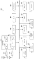
- a resource element group (REG: Resource element group) is used to define a mapping for PDCCH resource elements.
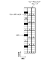
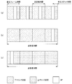
- FIG. 10 is an explanatory diagram for explaining an example of mapping of PDCCH resource element groups.
- the REG is defined by 4 or 5 resource elements in order from the lowest frequency in each OFDM symbol. Specifically, in an OFDM symbol including CRS, it is defined by five resource elements in order from the lowest frequency, and in OFDM not including CRS, it is defined by four resource elements.
- the REG has the resource element having the lowest frequency as a representative of the REG. Specifically, priority is given to the time direction, and an index is assigned to the representative of the REG by searching in the frequency direction next.
- Each CCE is composed of multiple REGs.
- one CCE is composed of nine REGs.
- Nine REGs constituting one CCE are selected by a cell ID and a predetermined interleaved pattern.
- the number of CCEs used for one PDCCH depends on the PDCCH format and is determined based on other parameters.
- the number of CCEs used for one PDCCH is also referred to as an aggregation level.
- the number of CCEs used for one PDCCH is determined based on the number of resource elements that can be used for PDCCH transmission in one RB (Resource Block) pair, the EPDCCH transmission method, and the like.
- the number of ECCEs used for one EPDCCH is 1, 2, 4, 8, 16, or 32.
- the number of EREGs used for one ECCE is determined based on, for example, the type of subframe and the type of cyclic prefix, and is 4 or 8.
- transmission methods of EPDCCH distributed transmission and localized transmission are supported.
- Each ECCE is composed of a plurality of enhanced resource element groups (EREG).
- EREG is used to define the mapping of EPDCCH to resource elements.
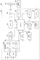
- FIG. 11 is an explanatory diagram for explaining an example of mapping of an EPDDCH extended resource element group.
- 16 EREGs numbered from 0 to 15, are defined. That is, EREG0 to EREG15 are defined in each RB pair.
- EREG0 to EREG15 are periodically defined by giving priority to the frequency direction with respect to resource elements other than resource elements to which predetermined signals and / or channels are mapped.
- the resource element to which the demodulation reference signal associated with the EPDCCH transmitted through the antenna ports 107 to 110 is mapped is not defined as EREG.
- the number of ECCEs used for one EPDCCH depends on the EPDCCH format and is determined based on other parameters.
- the number of ECCEs used for one EPDCCH is also referred to as an aggregation level.
- the number of ECCEs used for one EPDCCH is determined based on the number of resource elements that can be used for EPDCCH transmission in one RB pair, the EPDCCH transmission method, and the like.
- the number of ECCEs used for one EPDCCH is 1, 2, 4, 8, 16, or 32.
- the number of EREGs used for one ECCE is determined based on the type of subframe and the type of cyclic prefix, and is 4 or 8. As transmission methods of EPDCCH, distributed transmission and localized transmission are supported.
- the EPDCCH can use distributed transmission or local transmission. Distributed transmission and local transmission differ in the mapping of ECCE to EREG and RB pairs. For example, in distributed transmission, one ECCE is configured using EREGs of a plurality of RB pairs. In local transmission, one ECCE is configured using one RB pair of EREGs.
- the base station apparatus 1 performs settings related to the EPDCCH for the terminal apparatus 2.
- the terminal device 2 monitors a plurality of EPDCCHs based on the setting from the base station device 1.
- a set of RB pairs with which the terminal device 2 monitors the EPDCCH can be set.
- the set of RB pairs is also referred to as an EPDCCH set or an EPDCCH-PRB set.
- One or more EPDCCH sets can be set for one terminal device 2.
- Each EPDCCH set is composed of one or more RB pairs.
- the setting regarding EPDCCH can be performed individually for each EPDCCH set.
- the base station apparatus 1 can set a predetermined number of EPDCCH sets for the terminal apparatus 2. For example, up to two EPDCCH sets can be configured as EPDCCH set 0 and / or EPDCCH set 1. Each of the EPDCCH sets can be configured with a predetermined number of RB pairs. Each EPDCCH set constitutes one set of a plurality of ECCEs. The number of ECCEs configured in one EPDCCH set is determined based on the number of RB pairs set as the EPDCCH set and the number of EREGs used for one ECCE. When the number of ECCEs configured in one EPDCCH set is N, each EPDCCH set configures ECCEs numbered from 0 to N-1. For example, when the number of EREGs used for one ECCE is 4, an EPDCCH set composed of four RB pairs constitutes 16 ECCEs.
- CA and DC> ⁇ Details of CA and DC in this embodiment>
- the terminal device 2 is configured with a plurality of cells and can perform multicarrier transmission. Communication in which the terminal device 2 uses a plurality of cells is called CA (carrier aggregation) or DC (dual connectivity).
- CA carrier aggregation
- DC dual connectivity
- the contents described in the present embodiment can be applied to each or a part of a plurality of cells set for the terminal device 2.
- a cell set in the terminal device 2 is also referred to as a serving cell.
- a plurality of serving cells to be set include one primary cell (PCell: Primary Cell) and one or more secondary cells (SCell: Secondary Cell).
- PCell Primary Cell
- SCell Secondary Cell
- One primary cell and one or more secondary cells may be set for the terminal device 2 that supports CA.
- the primary cell is a serving cell in which an initial connection establishment procedure has been performed, a serving cell that has started a connection re-establishment procedure, or a cell designated as a primary cell in a handover procedure.
- the primary cell operates at the primary frequency.
- the secondary cell can be set after the connection is established or reconstructed.
- the secondary cell operates at the secondary frequency.
- the connection is also referred to as an RRC connection.
- DC is an operation in which a predetermined terminal device 2 consumes radio resources provided from at least two different network points.
- the network points are a master base station device (MeNB: Master eNB) and a secondary base station device (SeNB: Secondary eNB).
- the dual connectivity is that the terminal device 2 performs RRC connection at at least two network points. In dual connectivity, two network points may be connected by a non-ideal backhaul.
- a base station apparatus 1 connected to at least S1-MME (Mobility Management Entity) and serving as a mobility anchor of a core network is referred to as a master base station apparatus.
- the base station apparatus 1 that is not a master base station apparatus that provides additional radio resources to the terminal apparatus 2 is referred to as a secondary base station apparatus.
- the group of serving cells related to the master base station apparatus is also referred to as a master cell group (MCG).
- MCG master cell group
- a group of serving cells related to the secondary base station apparatus is also referred to as a secondary cell group (SCG).
- SCG secondary cell group
- the serving cell group is referred to as a cell group (CG).
- the primary cell belongs to MCG.
- SCG a secondary cell corresponding to a primary cell is referred to as a primary secondary cell (PSCell: Primary Secondary Cell).
- the PSCell base station apparatus constituting the pSCell
- the PSCell may support functions (capability, performance) equivalent to the PCell (base station apparatus constituting the PCell).
- only some functions of PCell may be supported by PSCell.
- PSCell may support a function of performing PDCCH transmission using a search space different from CSS or USS. Further, the PSCell may always be in an activated state.
- PSCell is a cell which can receive PUCCH.
- a radio bearer (data radio bearer (DRB: Date Radio Bearer) and / or signaling radio bearer (SRB)) may be individually allocated in the MeNB and SeNB.
- the duplex mode may be individually set for MCG (PCell) and SCG (PSCell).
- MCG (PCell) and SCG (PSCell) may not be synchronized with each other. That is, the MCG frame boundary and the SCG frame boundary do not have to coincide.
- a plurality of timing adjustment parameters (TAG: Timing Advance Group) may be set independently for MCG (PCell) and SCG (PSCell).
- the terminal device 2 transmits UCI corresponding to the cell in MCG only by MeNB (PCell), and transmits UCI corresponding to the cell in SCG only by SeNB (pSCell).
- PCell MeNB
- pSCell SeNB
- a transmission method using PUCCH and / or PUSCH is applied to each cell group.
- PUCCH and PBCH are transmitted only by PCell or PSCell.
- PRACH is transmitted only by PCell or PSCell unless a plurality of TAGs (Timing Advance Groups) are set between cells in CG.
- SPS Semi-Persistent Scheduling
- DRX Discontinuous Transmission
- the same DRX as the PCell or PSCell in the same cell group may be performed.
- information / parameters related to MAC settings are basically shared with PCell or PSCell in the same cell group. Some parameters may be set for each secondary cell. Some timers and counters may be applied only to PCell or PSCell.
- cells to which the TDD scheme is applied and cells to which the FDD scheme is applied may be aggregated.
- the present disclosure can be applied to either a cell to which TDD is applied or a cell to which FDD is applied.
- the terminal device 2 transmits information (supportedBandCombination) indicating a band combination in which CA and / or DC are supported by the terminal device 2 to the base station device 1.
- the terminal device 2 transmits to the base station device 1 information indicating whether or not simultaneous transmission and reception in the plurality of serving cells in different bands are supported for each band combination.
- the base station device 1 can use a plurality of methods as a method of assigning PDSCH and / or PUSCH resources to the terminal device 2.
- Resource allocation methods include dynamic scheduling, semi-persistent scheduling, multi-subframe scheduling, and cross-subframe scheduling.
- one DCI performs resource allocation in one subframe. Specifically, PDCCH or EPDCCH in a certain subframe performs scheduling for PDSCH in that subframe. PDCCH or EPDCCH in a certain subframe performs scheduling for PUSCH in a predetermined subframe after that subframe.
- one DCI performs resource allocation in one or more subframes.
- PDCCH or EPDCCH in a certain subframe performs scheduling for PDSCH in one or more subframes after a predetermined number of subframes.
- PDCCH or EPDCCH in a certain subframe performs scheduling for PUSCH in one or more subframes after a predetermined number of times from the subframe.
- the predetermined number can be an integer greater than or equal to zero.
- the predetermined number may be defined in advance or may be determined based on physical layer signaling and / or RRC signaling.
- consecutive subframes may be scheduled, or subframes having a predetermined period may be scheduled.
- the number of subframes to be scheduled may be predetermined or may be determined based on physical layer signaling and / or RRC signaling.
- one DCI performs resource allocation in one subframe.
- PDCCH or EPDCCH in a certain subframe performs scheduling for PDSCH in one subframe that is a predetermined number after that subframe.
- PDCCH or EPDCCH in a certain subframe performs scheduling for PUSCH in one subframe after a predetermined number of times from the subframe.
- the predetermined number can be an integer greater than or equal to zero.
- the predetermined number may be defined in advance or may be determined based on physical layer signaling and / or RRC signaling.
- continuous subframes may be scheduled, or subframes having a predetermined period may be scheduled.
- one DCI performs resource allocation in one or more subframes.
- the terminal device 2 sets information related to SPS by RRC signaling and detects PDCCH or EPDCCH for enabling SPS, the terminal device 2 enables processing related to SPS, and performs predetermined PDSCH and / or PUSCH based on the setting related to SPS.
- the terminal apparatus 2 detects PDCCH or EPDCCH for releasing SPS when SPS is valid, the terminal apparatus 2 releases (invalidates) SPS and stops receiving predetermined PDSCH and / or PUSCH.
- the release of the SPS may be performed based on a case where a predetermined condition is satisfied. For example, the SPS is released when a predetermined number of empty transmission data is received. Empty transmission of data for releasing SPS corresponds to MAC PDU (Protocol Data Unit) including zero MAC SDU (Service Data Unit).
- MAC PDU Protocol Data Unit
- MAC SDU Service Data Unit
- Information related to SPS by RRC signaling includes SPS C-RNTI, which is the RNTI of SPS, information related to PDSCH scheduled period (interval), information related to PUSCH scheduled period (interval), and settings for releasing SPS.
- SPS C-RNTI is the RNTI of SPS
- information related to PDSCH scheduled period (interval) information related to PUSCH scheduled period (interval)
- settings for releasing SPS information related to SPS by RRC signaling.
- SPS is supported only for primary cells and / or primary secondary cells.
- HARQ has various characteristics. HARQ transmits and retransmits transport blocks. In HARQ, a predetermined number of processes (HARQ processes) are used (set), and each of the processes operates independently in a stop-and-wait manner.
- HARQ processes a predetermined number of processes (HARQ processes) are used (set), and each of the processes operates independently in a stop-and-wait manner.
- HARQ is asynchronous and operates adaptively. That is, in the downlink, retransmission is always scheduled through the PDCCH.
- Uplink HARQ-ACK (response information) corresponding to downlink transmission is transmitted on PUCCH or PUSCH.
- the PDCCH notifies the HARQ process number indicating the HARQ process and information indicating whether the transmission is an initial transmission or a retransmission.
- HARQ operates synchronously or asynchronously.
- Downlink HARQ-ACK response information corresponding to uplink transmission is transmitted by PHICH.
- the operation of a terminal device is determined based on HARQ feedback received by the terminal device and / or PDCCH received by the terminal device. For example, when the PDCCH is not received and the HARQ feedback is ACK, the terminal apparatus does not perform transmission (retransmission) and retains data in the HARQ buffer. In that case, the PDCCH may be sent to resume retransmission.
- the terminal apparatus when the PDCCH is not received and the HARQ feedback is NACK, the terminal apparatus performs non-adaptive retransmission in a predetermined uplink subframe. For example, when a PDCCH is received, the terminal apparatus performs transmission or retransmission based on the content notified by the PDCCH regardless of the content of HARQ feedback.
- HARQ may be operated only asynchronously. That is, downlink HARQ-ACK is not transmitted, and retransmission in uplink may always be scheduled through PDCCH.
- HARQ-ACK indicates ACK, NACK, or DTX.
- HARQ-ACK indicates that the transport block (codeword, channel) corresponding to the HARQ-ACK has been correctly received (decoded).
- NACK indicates that the transport block (codeword, channel) corresponding to the HARQ-ACK has not been correctly received (decoded).
- HARQ-ACK is DTX, it indicates that there is no transport block (codeword, channel) corresponding to the HARQ-ACK (not transmitted).
- a predetermined number of HARQ processes are set (defined) in each of the downlink and the uplink. For example, in FDD, a maximum of 8 HARQ processes are used per serving cell. Also, for example, in TDD, the maximum number of HARQ processes is determined by uplink / downlink configuration. The maximum number of HARQ processes may be determined based on RTT (Round Trip Time). For example, if the RTT is 8 TTI, the maximum number of HARQ processes can be 8.
- HARQ information is composed of at least NDI (New Data Indicator) and TBS (Transport Block Size).
- NDI is information indicating whether the transport block corresponding to the HARQ information is initially transmitted or retransmitted.
- TBS is the size of the transport block.
- a transport block is a block of data in a transport channel (transport layer), and can be a unit for performing HARQ.
- the HARQ information further includes a HARQ process ID (HARQ process number).
- HARQ information further includes RV (Redundancy Version) which is information for designating information bits and parity bits after encoding for the transport block.
- RV Redundancy Version
- the HARQ information includes a set of NDI and TBS for each transport block.
- FIG. 12 is a diagram illustrating an example of LTE downlink resource element mapping in the present embodiment.
- the number of OFDM symbols in one resource block and one slot is 7, a set of resource elements in one resource block pair is shown.
- the first seven OFDM symbols in the time direction in the resource block pair are also referred to as slot 0 (first slot).
- the last seven OFDM symbols in the time direction in the resource block pair are also referred to as slot 1 (second slot).
- Each of the OFDM symbols in each slot (resource block) is indicated by OFDM symbol numbers 0 to 6.
- each of the subcarriers in the frequency direction in the resource block pair is indicated by subcarrier numbers 0-11.
- the subcarrier numbers are assigned differently over the system bandwidth. For example, when the system bandwidth is composed of 6 resource blocks, subcarriers to which subcarrier numbers 0 to 71 are assigned are used.
- the resource element (k, l) is a resource element indicated by a subcarrier number k and an OFDM symbol number l.
- Resource elements indicated by R0 to R3 indicate cell-specific reference signals of antenna ports 0 to 3, respectively.
- the cell-specific reference signals of the antenna ports 0 to 3 are also referred to as CRS (Cell-specific RS).
- CRS Cell-specific RS
- the CRS is a case of four antenna ports, but the number can be changed.
- CRS can use one antenna port or two antenna ports.
- the CRS can be shifted in the frequency direction based on the cell ID.
- the CRS can be shifted in the frequency direction based on the remainder obtained by dividing the cell ID by 6.
- Resource elements indicated by C1 to C4 indicate transmission path condition measurement reference signals (CSI-RS) of the antenna ports 15 to 22.
- Resource elements indicated by C1 to C4 indicate CSI-RSs of CDM group 1 to CDM group 4, respectively.
- the CSI-RS includes an orthogonal sequence (orthogonal code) using a Walsh code and a scramble code using a pseudo-random sequence.
- the CSI-RS is code division multiplexed by orthogonal codes such as Walsh codes in the CDM group.
- CSI-RSs are frequency division multiplexed (FDM) between CDM groups.
- the CSI-RS of the antenna ports 15 and 16 is mapped to C1.
- the CSI-RS of antenna ports 17 and 18 is mapped to C2.
- the CSI-RS of antenna ports 19 and 20 is mapped to C3.
- the CSI-RS of the antenna ports 21 and 22 is mapped to C4.
- the CSI-RS can be set as reference signals corresponding to the eight antenna ports of the antenna ports 15 to 22.
- the CSI-RS can be set as reference signals corresponding to the four antenna ports of the antenna ports 15 to 18.
- the CSI-RS can be set as a reference signal corresponding to two antenna ports of the antenna ports 15-16.
- the CSI-RS can be set as a reference signal corresponding to one antenna port of the antenna port 15.
- the CSI-RS can be mapped to some subframes, for example, can be mapped for each of a plurality of subframes. Multiple mapping patterns for CSI-RS resource elements are defined. Further, the base station apparatus 1 can set a plurality of CSI-RSs for the terminal apparatus 2.
- CSI-RS can make transmission power zero.
- CSI-RS with zero transmission power is also referred to as zero power CSI-RS.
- Zero power CSI-RS is set independently of CSI-RS of antenna ports 15-22.
- the CSI-RS of the antenna ports 15 to 22 is also referred to as non-zero power CSI-RS.
- the base station apparatus 1 sets CSI-RS as unique control information for the terminal apparatus 2 through RRC signaling.
- CSI-RS is set by the base station device 1 through RRC signaling.
- the CSI-IM resource that is a resource for measuring the interference power can be set in the terminal device 2.
- the terminal device 2 generates feedback information using CRS, CSI-RS and / or CSI-IM resources based on the setting from the base station device 1.
- Resource elements indicated by D1 and D2 indicate DL-DMRSs of CDM group 1 and CDM group 2, respectively.
- the DL-DMRS is configured using an orthogonal sequence (orthogonal code) using a Walsh code and a scramble sequence using a pseudo-random sequence.
- the DL-DMRS is independent for each antenna port and can be multiplexed within each resource block pair.
- DL-DMRS is orthogonal to each other between antenna ports due to CDM and / or FDM.
- the DL-DMRS is CDMed by orthogonal codes in the CDM group.
- DL-DMRSs are FDM between CDM groups.
- DL-DMRSs in the same CDM group are mapped to the same resource element.
- the DL-DMRSs in the same CDM group use different orthogonal sequences between antenna ports, and these orthogonal sequences are orthogonal to each other.
- the DL-DMRS for PDSCH can use a part or all of the eight antenna ports (antenna ports 7 to 14). That is, the PDSCH associated with the DL-DMRS can perform MIMO transmission up to 8 ranks.
- the DL-DMRS for EPDCCH can use part or all of the four antenna ports (antenna ports 107 to 110). Also, the DL-DMRS can change the CDM spreading code length and the number of mapped resource elements in accordance with the number of ranks of associated channels.
- the DL-DMRS for PDSCH transmitted through the antenna ports 7, 8, 11 and 13 is mapped to the resource element indicated by D1.
- the DL-DMRS for PDSCH transmitted at antenna ports 9, 10, 12 and 14 is mapped to the resource element indicated by D2.
- the DL-DMRS for EPDCCH transmitted through the antenna ports 107 and 108 is mapped to the resource element indicated by D1.
- the DL-DMRS for EPDCCH transmitted through antenna ports 109 and 110 is mapped to the resource element indicated by D2.
- FIG. 13 is a diagram illustrating an example of NR downlink resource element mapping in the present embodiment.
- FIG. 13 shows a set of resource elements in a predetermined resource when parameter set 0 is used.
- the predetermined resource shown in FIG. 13 is a resource having the same time length and frequency bandwidth as one resource block pair in LTE.
- a predetermined resource is also referred to as NR-RB (NR resource block).
- the predetermined resource can be used as a unit for allocation of NR-PDSCH or NR-PDCCH, a unit for defining mapping to a resource element of a predetermined channel or a predetermined signal, or a unit in which a parameter set is set. .
- the predetermined resource includes 14 OFDM symbols indicated by OFDM symbol numbers 0 to 13 in the time direction, and 12 subcarriers indicated by subcarrier numbers 0 to 11 in the frequency direction. Is done.
- the subcarrier number is allocated over the system bandwidth.
- Resource elements indicated by C1 to C4 indicate transmission path condition measurement reference signals (CSI-RS) of the antenna ports 15 to 22.
- Resource elements indicated by D1 to D2 indicate DL-DMRSs of CDM group 1 to CDM group 2, respectively.
- FIG. 14 is a diagram illustrating an example of NR downlink resource element mapping in the present embodiment.
- FIG. 14 shows a set of resource elements in a predetermined resource when the parameter set 1 is used.
- the predetermined resource shown in FIG. 14 is a resource having the same time length and frequency bandwidth as one resource block pair in LTE.
- the predetermined resource is composed of seven OFDM symbols indicated by OFDM symbol numbers 0 to 6 in the time direction and 24 subcarriers indicated by subcarrier numbers 0 to 23 in the frequency direction. Is done.
- the subcarrier number is allocated over the system bandwidth.
- Resource elements indicated by C1 to C4 indicate transmission path condition measurement reference signals (CSI-RS) of the antenna ports 15 to 22.
- Resource elements indicated by D1 to D2 indicate DL-DMRSs of CDM group 1 to CDM group 2, respectively.
- FIG. 15 is a diagram illustrating an example of NR downlink resource element mapping in the present embodiment.
- FIG. 15 shows a set of resource elements in a predetermined resource when the parameter set 1 is used.
- the predetermined resource shown in FIG. 15 is a resource having the same time length and frequency bandwidth as one resource block pair in LTE.
- the predetermined resource is composed of 28 OFDM symbols indicated by OFDM symbol numbers 0 to 27 in the time direction, and 6 subcarriers indicated by subcarrier numbers 0 to 6 in the frequency direction. Is done.
- the subcarrier number is allocated over the system bandwidth.
- Resource elements indicated by C1 to C4 indicate transmission path condition measurement reference signals (CSI-RS) of the antenna ports 15 to 22.
- Resource elements indicated by D1 to D2 indicate DL-DMRSs of CDM group 1 to CDM group 2, respectively.
- FIG. 16 shows an example of a frame configuration of self-contained transmission in the present embodiment.
- one transmission / reception is configured in the order of downlink transmission, GP, and continuous downlink transmission from the top.
- the continuous downlink transmission includes at least one downlink control information and DMRS.
- the downlink control information instructs reception of a downlink physical channel included in the continuous downlink transmission or transmission of an uplink physical channel included in the continuous uplink transmission.
- the terminal device 2 When the downlink control information instructs reception of the downlink physical channel, the terminal device 2 tries to receive the downlink physical channel based on the downlink control information. And the terminal device 2 transmits the reception success or failure (decoding success or failure) of the downlink physical channel through the uplink control channel included in the uplink transmission allocated after the GP. On the other hand, when the downlink control information instructs the transmission of the uplink physical channel, the uplink physical channel transmitted based on the downlink control information is included in the uplink transmission for transmission. In this way, by flexibly switching between uplink data transmission and downlink data transmission according to the downlink control information, it is possible to immediately cope with an increase / decrease in the uplink / downlink traffic ratio. Further, downlink low-delay communication can be realized by notifying the success or failure of downlink reception by uplink transmission immediately after.
- the unit slot time is the minimum time unit that defines downlink transmission, GP, or uplink transmission. Unit slot time is reserved for either downlink transmission, GP, or uplink transmission. The unit slot time does not include both downlink transmission and uplink transmission.
- the unit slot time may be the minimum transmission time of a channel associated with the DMRS included in the unit slot time.
- One unit slot time is defined by, for example, an NR sampling interval (T s ) or an integer multiple of a symbol length.
- the unit frame time may be a minimum time specified by scheduling.
- the unit frame time may be a minimum unit in which a transport block is transmitted.
- the unit slot time may be the maximum transmission time of a channel associated with the DMRS included in the unit slot time.
- the unit frame time may be a unit time for determining the uplink transmission power in the terminal device 2.
- the unit frame time may be referred to as a subframe.
- One unit frame time is defined by, for example, an NR sampling interval (T s ), a symbol length, or an integer multiple of a unit slot time.
- the transmission / reception time is one transmission / reception time. Between one transmission / reception and another transmission / reception, time (gap) in which no physical channel and physical signal are transmitted is occupied. The terminal device 2 should not average CSI measurements between different transmissions and receptions.
- the transmission / reception time may be referred to as TTI.
- One transmission / reception time is defined by, for example, an NR sampling interval (T s ), a symbol length, a unit slot time, or an integer multiple of a unit frame time.
- ⁇ Supported reception bandwidth of NR terminal apparatus in this embodiment> In LTE, except for a predetermined terminal category, in order for a terminal device to connect to a cell, it is necessary to support the system bandwidth used in the cell. As a specific example, when a cell is operated with a system bandwidth of 20 MHz, the terminal device can also connect to the cell by supporting the reception bandwidth of 20 MHz. On the other hand, when the terminal device can only support a reception bandwidth of less than 20 MHz, it is difficult for the terminal device to connect to the cell.
- the terminal device does not necessarily support the system bandwidth. Specifically, even when the base station (cell) is operated with a system bandwidth of 20 MHz and the terminal device does not support a reception bandwidth of 10 MHz or more, the terminal device is connected to the cell in NR. Thus, it is possible to receive a downlink channel (PDCCH) and downlink data (PDSCH) for controlling physical layer parameters necessary for communication. As a result, it is possible to flexibly design the reception bandwidth of the terminal device, and to reduce the manufacturing cost of the terminal device.
- PDCH downlink channel
- PDSCH downlink data
- FIG. 17 is an explanatory diagram for describing an example of a reception band of a terminal device in NR.
- the example shown as (a) in FIG. 17 shows an example in which the center frequencies of the reception bands substantially match among a plurality of terminal devices.
- the center frequency of the reception band of a plurality of terminal devices for example, the center frequency of the NR carrier, the center frequency of NR-PSS / NR-SSS transmitted in common between terminal devices, and transmitted in common between terminal devices.
- the frequency position based on the frequency offset reported from the center frequency of NR-PSS / NR-SSS in common to terminals, the subcarrier not transmitted by the DC carrier, the frequency position set from the upper layer such as the RRC layer, etc. Can be mentioned.
- the example shown as (b) in FIG. 17 shows an example in which the center frequency of the reception band is different among a plurality of terminal devices.
- the center frequency of the reception band of each of the plurality of terminal devices for example, the center frequency of NR-PSS / NR-SSS transmitted individually to each terminal device, and the NR-PSS / NR transmitted in common between the terminal devices -Frequency position based on frequency offset information individually notified to each terminal device from the center frequency of SSS, frequency position set from higher layers such as RRC layer, and the like.
- the terminal apparatus Based on NR-PSS / NR-SSS and information notified from the base station apparatus, the terminal apparatus specifies a frequency band in which the terminal apparatus can receive the downlink physical channel and the downlink physical signal. .
- the terminal device may dynamically change the received bandwidth within the range of the supported reception bandwidth. For example, the terminal device receives a downlink physical channel and a downlink physical signal with a bandwidth of 5 MHz from the initial access until the RRC connection is established. After the RRC connection is established, the terminal device has a bandwidth of 20 MHz. You may receive a downlink physical channel and a downlink physical signal. At this time, for example, the terminal device may switch the bandwidth to be received based on an instruction by the RRC message. As another example, the terminal device may switch the bandwidth to be received based on an instruction using the NR-PDCCH using a bandwidth that can be received in common between the terminal devices. As another example, the terminal device may switch the bandwidth to be received based on the information on the random access response. As another example, the terminal device may switch the bandwidth to be received based on contention resolution information notifying completion of random access.
- the terminal device may dynamically change the center frequency of the frequency band received by the terminal device. For example, the terminal device uses the center frequency of NR-PSS / NR-SSS as the center frequency of the reception band from the initial access until the RRC connection is established, and is instructed by the RRC layer after the RRC connection is established.
- the center frequency may be the center frequency of the reception band.
- the terminal device may switch the center frequency of the band to be received based on an instruction by the RRC message.
- the terminal device may switch the center frequency of the received band based on an instruction using the NR-PDCCH using a bandwidth that can be received in common among a plurality of terminal devices.
- the terminal device may switch the center frequency of the band to be received based on the information on the random access response.
- the terminal device may switch the center frequency of the band to be received based on the contention resolution information notifying completion of random access.
- Information for instructing the change of the bandwidth and / or center frequency of the frequency band received by the terminal device includes, for example, center frequency and / or bandwidth information, resource block information, information indicating a predetermined hopping pattern, and the like. Can be mentioned.
- a band received in common between a plurality of terminal apparatuses is a band in which the terminal apparatus receives at least once when initially connected to the cell or carrier.
- the band received for each terminal device is a band other than the band in which the terminal device receives at least once when initially connected to the cell or carrier.
- the band received in common between a plurality of terminal devices is a band that can be received by a terminal device (an RRC idle state terminal device) for which RRC connection has not been established.
- the band received individually for each terminal device is a band that cannot be received by a terminal device that has not established an RRC connection, and a terminal device that has established an RRC connection (a terminal device in an RRC connection state). ) Is a receivable band.
- a reference signal known in common between the plurality of terminal devices is arranged.
- the reference signal comprises a series of symbols only with system information and / or preset information.
- a known reference signal notified for each terminal device is arranged.
- a symbol sequence is configured by information (for example, terminal device identifier, RNTI, etc.) set for each terminal device from an upper layer such as the RRC layer.
- a synchronization signal for example, NR-PSS / SSS
- a broadcast channel or NR-PDSCH including system information, a random access response, or paging is arranged in a band received in common among a plurality of terminal apparatuses.
- a band received in common among a plurality of terminal apparatuses is transmitted / received at a subcarrier interval of a default interval (for example, 15 kHz), and a band received individually for each terminal device has a subcarrier interval different from the default frequency. Transmission / reception is performed at subcarrier intervals (for example, 30 kHz).
- a band received in common among a plurality of terminal apparatuses may be referred to as an anchor band.
- the band received in common among a plurality of terminal devices and the band received individually for each terminal device include a frequency portion and a frequency resource group (Frequency).
- Resource Group: FRG frequency resource group
- the NR-PDCCH is used for scheduling the NR-PDSCH for a predetermined terminal device.
- the NR-PDCCH is used for scheduling the NR-PUSCH for a predetermined terminal device.
- the NR-PDCCH is used for performing control in a physical layer for a predetermined terminal device or terminal device group.
- the terminal device in the NR attempts to receive the NR-PDCCH in order to perform NR-PDSCH reception, NR-PUSCH transmission, and control information reception in the physical layer.
- the terminal device is set with a parameter list necessary for monitoring and receiving the NR-PDCCH from the base station device.
- the parameter list includes information indicating time-axis resources, information indicating frequency-axis resources, information indicating space-axis resources, information indicating code-axis resources, MCS (Modulation and Coding Scheme), and logic of NR-PDCCH. Contains all or part of the information about the parameter.
- the base station apparatus can flexibly arrange NR-PDCCH. Therefore, the base station apparatus can store different RATs (Radio Access Technology) such as NR and LTE having different physical parameter sets corresponding to various use cases in one NR carrier. Then, the base station apparatus notifies the terminal apparatus of information related to the time-axis and / or frequency-axis resources of the NR-PDCCH, so that the terminal apparatus has a part of bandwidth provided by the base station apparatus. In this case, at least downlink communication is possible.
- RATs Radio Access Technology
- Examples of information indicating time-axis resources of NR-PDCCH include the number of symbols and / or the number of subframes, symbols indicating the start or end of NR-PDCCH arrangement, the period or subframe pattern for monitoring NR-PDCCH And the number of repetitions of NR-PDCCH, and the like.
- Examples of information indicating the frequency axis resource of NR-PDCCH include the number of resource blocks and resource block allocation information.
- Examples of the information indicating the spatial axis resource of the NR-PDCCH include the number of antennas and / or antenna ports through which the NR-PDCCH is transmitted.
- Examples of information indicating the NR-PDCCH code axis resource include scramble patterns or scramble IDs of demodulation reference signals associated with NR-PDCCH and NR-PDCCH.
- Examples of information on the physical parameters of the NR system include a subframe length, a radio frame length, a symbol length, a cyclic prefix length, and a subcarrier interval.
- Information on the logical parameters of NR-PDCCH includes the number of NR-REGs included in one NR-CCE, the number of NR-CCEs included in one NR-PDCCH format, the start position of CCE in each search space, and blind coding And the number of NR-PDCCH candidates as well as information indicating a local arrangement or a distributed arrangement.
- the NR-PDCCH is divided into an area that is set so that it can be received in common between terminal apparatuses and an area that is set so that each terminal apparatus can receive individually. Is possible.
- the parameter list may be divided into a parameter list that is commonly set between terminal devices and a parameter list that is individually set for each terminal device. Further, two predetermined parameters may be set: a parameter common to the terminal devices and an individual parameter for each terminal device.
- the start position of the NR-PDCCH search space may differ depending on the contents of the physical channel (for example, at least one of the logical physical channel, the format, and the message type).
- the search space start position of NR-PDCCH differs between NR-PDCCH that schedules NR-PDSCH carrying NR-DL-SCH and NR-PDCCH that schedules NR-PDSCH carrying NR-SIB. May be.
- the NR-PDCCH search space start position differs between NR-PDCCH that schedules NR-PDSCH carrying NR-SIB1 and NR-PDCCH that schedules NR-PDSCH carrying NR-SIB2. May be.
- a predetermined procedure is used after separation by logical parameters in one NR-PDCCH.
- NR-PDCCH downlink physical control channel
- NR-CCE which is a logical control channel element constituting NR-PDCCH
- NR-CCE group first NR-CCE group
- second NR-CCE group second NR-CCE group
- FIG. 18 is an explanatory diagram for explaining an example of the configuration of NR-CCE and mapping to NR-PDCCH.
- NR-CCE # 0 to NR-CCE # 3 are mapped to a frequency band common to a plurality of terminal devices (in other words, a region common to a plurality of terminal devices), and NR-CCE # 4 To NR-CCE # 7 is mapped to an individual area for each terminal apparatus.
- a frequency band common to a plurality of terminal devices means that reception can be performed in common among a plurality of terminal devices connected to the NR carrier even between terminal devices having different support reception bandwidths. Bandwidth.
- the individual frequency band for each terminal device is a bandwidth that can be received only by a predetermined terminal device or terminal device group.
- a search space common to a plurality of terminal devices is arranged only in the NR-CCE group mapped to a frequency band common to the plurality of terminal devices.
- a search space unique to each terminal apparatus can be arranged in all NR-CCEs. Therefore, for example, in the example shown in FIG. 18, NR-PDCCH in which NR-CCE # 0 to # 3 are mapped to a bandwidth in which the reception bandwidth of the first terminal device and the reception bandwidth of the second terminal device overlap each other. Is arranged.
- NR-PDCCH to which NR-CCE # 4 to # 7 are mapped is arranged in the bandwidth that can be received only by the second terminal apparatus.
- FIG. 19 is an explanatory diagram for explaining an example of mapping of NR-CCE to NR-PDCCH.
- each of the first terminal device and the second terminal device receives the center frequency of the system bandwidth. Further, the second terminal device supports a wider reception bandwidth than the first terminal device.
- the first terminal apparatus receives NR-PDCCH using NR-CCE # 0 to NR-CCE # 3. Further, the second terminal apparatus receives NR-PDCCH using NR-CCE # 0 to NR-CCE # 7.
- a common mapping rule is used between the first terminal device and the second terminal device for NR-CCE # 0 to NR-CCE # 3 for the purpose of reducing overhead of the control signal. .
- FIG. 20 is an explanatory diagram for explaining an example of mapping of NR-CCE to NR-PDCCH.
- NR-CCEs # 4 to # 7 of the first terminal apparatus are difficult to be arranged in the frequency direction, and are thus shifted on the time axis. This makes it possible to extend the coverage of the NR-PDCCH of the first terminal device.
- N CCE, k and N ECCE, p, k described above as (Equation 1) and (Equation 2) are individually set for each terminal apparatus.
- N CCE, k and N ECCE, p, k are determined based on a bandwidth that can be received by the terminal device.
- the NR-CCE may be sequentially mapped so that the center frequency of the NR carrier is a base point and is spaced from the base point along the frequency axis.
- NR-CCE is mapped as shown in FIGS.
- examples of the center of the NR carrier include information on the center frequency of the NR carrier (CenterFreq) indicated by the RRC layer, the center of the NR-PSS and / or NR-SSS signal, and the DC carrier. .
- the center frequency detection method in the terminal device there is a method of detecting the center frequency based on the detection of NR-PSS and / or NR-SSS.
- the terminal apparatus detects the center of NR-PSS and / or NR-SSS from the signal sequence of NR-PSS and / or NR-SSS.
- the terminal apparatus assumes that the center of the NR-PSS and / or NR-SSS is the center of the NR carrier.
- Another example of the center frequency detection method in the terminal device is a method of detecting the center frequency based on subcarriers in which no signal is transmitted as a DC carrier.
- the terminal apparatus detects a subcarrier in which transmission is not performed in one NR carrier (that is, transmission is performed at zero power), and the center of the subcarrier is determined as the center of the NR carrier. Assume central. Note that the information on the center frequency of the NR carrier may be notified to the terminal device by NR-MIB.
- the NR-CCE is mapped in such a manner that the center frequency of the NR carrier is the base point and is sequentially separated from the base point along the frequency axis, thereby achieving both local transmission and distributed transmission.
- NR-PDCCH using NR-CCE having a small index
- space control such as beam forming becomes easy.
- NR-PDCCH using NR-CCE having a large index it is possible to realize frequency-distributed transmission and facilitate frequency diversity.
- the NR-CCE may be sequentially mapped so as to be separated from the base point along the frequency axis, with the center of the bandwidth common among the plurality of terminal apparatuses as the base point.
- the center of the bandwidth common to a plurality of terminal apparatuses for example, information on the center frequency of the NR carrier (CenterFreq) indicated by the RRC layer, the center of the signal of NR-PSS and / or NR-SSS, etc. Is mentioned.
- NR-CCE may be mapped based on information of NR-MIB. Specifically, bandwidth information that can be received in common among terminal devices is notified to the terminal device by NR-MIB, and NR-CCEs are sequentially mapped from the bandwidth. Note that the NR-CCE may be mapped based on information of the dedicated RRC layer.
- NR-CCE mapped to a bandwidth received in common between terminal apparatuses is based on the center of the bandwidth from the base point. You may map sequentially so that it may space apart along a frequency axis. At this time, the bandwidth individually received by each terminal device may be mapped based on information from an upper layer such as the RRC layer.
- the NR-CCE may be mapped to a resource element or a resource element group after being interleaved in a predetermined bandwidth and / or section.
- the NR-CCE mapped to the bandwidth and / or section that can be received in common between the terminal apparatuses is interleaved in the bandwidth and / or section that can be received in common between the terminal apparatuses. It may be mapped to a resource element or resource element group.
- the NR-CCE mapped to the bandwidth and / or section individually received by each terminal device is the resource element or after being interleaved in the bandwidth and / or section individually received by each terminal device. It may be mapped to a resource element group.
- the NR-PDCCH can obtain frequency and / or diversity in the time direction.
- NR-PDCCH NR downlink physical control channel
- first NR-PDCCH Set first NR-PDCCH Set
- second NR-PDCCH region second NR-PDCCH Set
- FIG. 21 is an explanatory diagram for explaining an example of the reception bandwidth of the terminal device and the NR-PDCCH region.
- the first terminal device and the second terminal device receive the center frequency of the system bandwidth. Further, the second terminal device supports a wider reception bandwidth than the first terminal device.
- the region to which the first NR-PDCCH is allocated (hereinafter also referred to as “first NR-PDCCH Set”) has a reception bandwidth between the first terminal device and the second terminal device. Arranged in overlapping frequency bands.
- a second NR-PDCCH Set different from the first NR-PDCCH Set is arranged unique to each terminal device. The second NR-PDCCH Set corresponds to an area to which the second NR-PDCCH is allocated.
- the example shown as (b) in FIG. 21 shows another example of the reception bandwidth of the terminal apparatus and the NR-PDCCH region.
- the example shown as (b) is set so that the center of the reception bandwidth of the first terminal device is different from the center of the reception bandwidth of the second terminal device. Yes.
- the first NR-PDCCH Set is arranged in a frequency band in which the reception band of the first terminal device and the reception band of the second terminal device overlap, and only the first terminal device can receive.
- the second NR-PDCCH Set corresponding to each of the first terminal device and the second terminal device is arranged.
- FIG. 21 is described focusing on only two terminal devices (that is, the first terminal device and the second terminal device) for the sake of simplification, but there are three or more terminal devices.
- the present embodiment can also be applied to the above.
- the first NR-PDCCH region is set so that it can be monitored and received in common between terminal devices connected to the NR cell.
- CSS and USS are arranged in the first NR-PDCCH region.
- the first NR-PDCCH region is obtained, for example, when decoding NR-PBCH, information obtained when detecting NR-PSS / NR-SSS. It may be set based on information, information included in the NR-MIB, and the like. In this case, the terminal device attempts to receive (monitor) the first NR-PDCCH based on the information.
- the first NR-PDCCH region may be arranged in a bandwidth that can be commonly received between terminal apparatuses.
- the terminal device attempts to receive (monitor) the first NR-PDCCH arranged in the bandwidth.
- the bandwidth that can be received in common between the terminal devices can correspond to, for example, the bandwidth in which the NR-PSS / NR-SSS received in common between the terminal devices is arranged.
- a transmission / reception point TRP, cell
- TRP transmission / reception point
- a beam For example, PCI: Physical Cell Identity, VCI: Virtial Cell Identity, TRPI: Transmission and Reception Point Identity, BI: Beam Identity, Scramble Identity
- physical parameters include symbol length, cyclic prefix (CP) length, subcarrier spacing (SCS), radio frame length, subframe length, and the like.
- Examples of information obtained when decoding the NR-PBCH include the number of antenna ports to which the NR-PBCH is transmitted and the SFN (system frame number).
- the terminal device can also decode NR-PBCH before monitoring NR-PDCCH. Therefore, by including the NR-PDCCH setting parameter in the NR-MIB carried by the NR-PBCH, the NR-PDCCH can be flexibly set for each system.
- the second NR-PDCCH region is set so that it can be monitored and received individually for each terminal device or terminal device group connected to the NR. At least the USS is arranged in the second NR-PDCCH region. A CSS may also be arranged for the second NR-PDCCH region.
- the second NR-PDCCH may be uniquely notified to each terminal device by a dedicated RRC message (Dedicated RRC message).
- the terminal device attempts to receive the second NR-PDCCH based on information regarding the second NR-PDCCH included in the RRC message.
- the second NR-PDCCH may be notified by the first NR-PDCCH.
- the terminal device tries to receive the first NR-PDCCH first. If the terminal device cannot decode the first NR-PDCCH addressed to the terminal device, the terminal device does not expect to receive downlink data (NR-PDSCH) in the NR frame. On the other hand, when the terminal device can decode the first NR-PDCCH addressed to the terminal device, the terminal device receives the second NR-PDCCH from the downlink control information included in the first NR-PDCCH. Information necessary for this is acquired, and decoding of the second NR-PDCCH is attempted based on the information.
- NR-PDSCH downlink data
- the second NR-PDCCH may be notified by NR-PCFICH.
- the second NR-PDCCH may be notified by the NR-SIB in a manner unique to the terminal device group.
- the NR-SIB is carried by the NR-PDSCH scheduled on the first NR-PDCCH.
- the terminal device may monitor at least the first NR-PDCCH when the second NR-PDCCH monitoring is not set.
- the terminal device may monitor the first NR-PDCCH and the second NR-PDCCH when the second NR-PDCCH monitoring is set. Note that the terminal device may not monitor the first NR-PDCCH when the second NR-PDCCH is set to be monitored.
- the base station device 1 may be realized as any type of eNB (evolved Node B) such as a macro eNB or a small eNB.
- the small eNB may be an eNB that covers a cell smaller than a macro cell, such as a pico eNB, a micro eNB, or a home (femto) eNB.
- the base station apparatus 1 may be realized as another type of base station such as Node B or BTS (Base Transceiver Station).
- the base station apparatus 1 may include a main body (also referred to as a base station apparatus) that controls wireless communication and one or more RRHs (Remote Radio Heads) that are arranged at locations different from the main body. Further, various types of terminals to be described later may operate as the base station device 1 by temporarily or semi-permanently executing the base station function. Furthermore, at least a part of the components of the base station device 1 may be realized in a base station device or a module for the base station device.
- RRHs Remote Radio Heads
- the terminal device 2 is a smartphone, a tablet PC (Personal Computer), a notebook PC, a portable game terminal, a mobile terminal such as a portable / dongle type mobile router or a digital camera, or an in-vehicle terminal such as a car navigation device. It may be realized as.
- the terminal device 2 may be realized as a terminal (also referred to as an MTC (Machine Type Communication) terminal) that performs M2M (Machine To Machine) communication.
- MTC Machine Type Communication
- M2M Machine To Machine
- at least a part of the components of the terminal device 2 may be realized in a module (for example, an integrated circuit module configured by one die) mounted on these terminals.
- FIG. 22 is a block diagram illustrating a first example of a schematic configuration of an eNB to which the technology according to the present disclosure may be applied.
- the eNB 800 includes one or more antennas 810 and a base station device 820. Each antenna 810 and the base station apparatus 820 can be connected to each other via an RF cable.
- Each of the antennas 810 has a single or a plurality of antenna elements (for example, a plurality of antenna elements constituting a MIMO antenna), and is used for transmission and reception of radio signals by the base station apparatus 820.
- the eNB 800 includes a plurality of antennas 810 as illustrated in FIG. 22, and the plurality of antennas 810 may respectively correspond to a plurality of frequency bands used by the eNB 800, for example. 22 shows an example in which the eNB 800 includes a plurality of antennas 810, but the eNB 800 may include a single antenna 810.
- the base station apparatus 820 includes a controller 821, a memory 822, a network interface 823, and a wireless communication interface 825.
- the controller 821 may be a CPU or a DSP, for example, and operates various functions of the upper layer of the base station apparatus 820. For example, the controller 821 generates a data packet from the data in the signal processed by the wireless communication interface 825, and transfers the generated packet via the network interface 823. The controller 821 may generate a bundled packet by bundling data from a plurality of baseband processors, and may transfer the generated bundled packet. In addition, the controller 821 is a logic that executes control such as radio resource control, radio bearer control, mobility management, inflow control, or scheduling. May have a typical function. Moreover, the said control may be performed in cooperation with a surrounding eNB or a core network node.
- the memory 822 includes RAM and ROM, and stores programs executed by the controller 821 and various control data (for example, terminal list, transmission power data, scheduling data, and the like).
- the network interface 823 is a communication interface for connecting the base station device 820 to the core network 824.
- the controller 821 may communicate with the core network node or other eNB via the network interface 823.
- the eNB 800 and the core network node or another eNB may be connected to each other by a logical interface (for example, an S1 interface or an X2 interface).
- the network interface 823 may be a wired communication interface or a wireless communication interface for wireless backhaul.
- the network interface 823 may use a frequency band higher than the frequency band used by the wireless communication interface 825 for wireless communication.
- the wireless communication interface 825 supports any cellular communication scheme such as LTE (Long Term Evolution) or LTE-Advanced, and provides a wireless connection to terminals located in the cell of the eNB 800 via the antenna 810.
- the wireless communication interface 825 may typically include a baseband (BB) processor 826, an RF circuit 827, and the like.
- the BB processor 826 may perform, for example, encoding / decoding, modulation / demodulation, and multiplexing / demultiplexing, and each layer (for example, L1, MAC (Medium Access Control), RLC (Radio Link Control), and PDCP).
- Various signal processing of Packet Data Convergence Protocol
- Packet Data Convergence Protocol is executed.
- the BB processor 826 may have some or all of the logical functions described above instead of the controller 821.
- the BB processor 826 may be a module that includes a memory that stores a communication control program, a processor that executes the program, and related circuits. The function of the BB processor 826 may be changed by updating the program. Good.
- the module may be a card or a blade inserted into a slot of the base station apparatus 820, or a chip mounted on the card or the blade.
- the RF circuit 827 may include a mixer, a filter, an amplifier, and the like, and transmits and receives a radio signal via the antenna 810.
- the radio communication interface 825 includes a plurality of BB processors 826 as illustrated in FIG. 22, and the plurality of BB processors 826 may respectively correspond to a plurality of frequency bands used by the eNB 800, for example. Further, the wireless communication interface 825 includes a plurality of RF circuits 827 as shown in FIG. 22, and the plurality of RF circuits 827 may respectively correspond to a plurality of antenna elements, for example. 22 illustrates an example in which the wireless communication interface 825 includes a plurality of BB processors 826 and a plurality of RF circuits 827, the wireless communication interface 825 includes a single BB processor 826 or a single RF circuit 827. But you can.
- the eNB 800 includes a module including a part (for example, the BB processor 826) or all of the wireless communication interface 825 and / or the controller 821, and the one or more components are mounted in the module. Good.
- the module stores a program for causing the processor to function as the one or more components (in other words, a program for causing the processor to execute the operation of the one or more components). The program may be executed.
- a program for causing a processor to function as the one or more components is installed in the eNB 800, and the radio communication interface 825 (eg, the BB processor 826) and / or the controller 821 executes the program.
- the eNB 800, the base station apparatus 820, or the module may be provided as an apparatus including the one or more components, and a program for causing a processor to function as the one or more components is provided. May be.
- a readable recording medium in which the program is recorded may be provided.
- the reception unit 105 and the transmission unit 107 described with reference to FIG. 8 may be implemented in the wireless communication interface 825 (for example, the RF circuit 827).
- the transmission / reception antenna 109 may be mounted on the antenna 810.
- the network communication unit 130 may be implemented in the controller 821 and / or the network interface 823.
- FIG. 23 is a block diagram illustrating a second example of a schematic configuration of an eNB to which the technology according to the present disclosure may be applied.
- the eNB 830 includes one or more antennas 840, a base station apparatus 850, and an RRH 860. Each antenna 840 and RRH 860 may be connected to each other via an RF cable. Base station apparatus 850 and RRH 860 can be connected to each other via a high-speed line such as an optical fiber cable.
- Each of the antennas 840 has a single or a plurality of antenna elements (for example, a plurality of antenna elements constituting a MIMO antenna), and is used for transmission / reception of radio signals by the RRH 860.
- the eNB 830 includes a plurality of antennas 840 as illustrated in FIG. 23, and the plurality of antennas 840 may respectively correspond to a plurality of frequency bands used by the eNB 830, for example. Note that although FIG. 23 illustrates an example in which the eNB 830 includes a plurality of antennas 840, the eNB 830 may include a single antenna 840.
- the base station device 850 includes a controller 851, a memory 852, a network interface 853, a wireless communication interface 855, and a connection interface 857.
- the controller 851, the memory 852, and the network interface 853 are the same as the controller 821, the memory 822, and the network interface 823 described with reference to FIG.
- the wireless communication interface 855 supports a cellular communication method such as LTE or LTE-Advanced, and provides a wireless connection to a terminal located in a sector corresponding to the RRH 860 via the RRH 860 and the antenna 840.
- the wireless communication interface 855 may typically include a BB processor 856 and the like.
- the BB processor 856 is the same as the BB processor 826 described with reference to FIG. 22 except that it is connected to the RF circuit 864 of the RRH 860 via the connection interface 857.
- the wireless communication interface 855 includes a plurality of BB processors 856 as illustrated in FIG. 22, and the plurality of BB processors 856 may respectively correspond to a plurality of frequency bands used by the eNB 830, for example.
- 23 shows an example in which the wireless communication interface 855 includes a plurality of BB processors 856, the wireless communication interface 855 may include a single BB processor 856.
- connection interface 857 is an interface for connecting the base station device 850 (wireless communication interface 855) to the RRH 860.
- the connection interface 857 may be a communication module for communication on the high-speed line that connects the base station apparatus 850 (wireless communication interface 855) and the RRH 860.
- the RRH 860 includes a connection interface 861 and a wireless communication interface 863.
- connection interface 861 is an interface for connecting the RRH 860 (wireless communication interface 863) to the base station device 850.
- the connection interface 861 may be a communication module for communication on the high-speed line.
- the wireless communication interface 863 transmits and receives wireless signals via the antenna 840.
- the wireless communication interface 863 may typically include an RF circuit 864 and the like.
- the RF circuit 864 may include a mixer, a filter, an amplifier, and the like, and transmits and receives wireless signals via the antenna 840.
- the wireless communication interface 863 includes a plurality of RF circuits 864 as illustrated in FIG. 23, and the plurality of RF circuits 864 may correspond to, for example, a plurality of antenna elements, respectively.
- FIG. 23 illustrates an example in which the wireless communication interface 863 includes a plurality of RF circuits 864, but the wireless communication interface 863 may include a single RF circuit 864.
- the eNB 830 illustrated in FIG. 23 one or more components of the upper layer processing unit 101 and the control unit 103 described with reference to FIG. 8 are implemented in the wireless communication interface 855 and / or the wireless communication interface 863. Also good. Alternatively, at least some of these components may be implemented in the controller 851. As an example, the eNB 830 includes a module including a part (for example, the BB processor 856) or the whole of the wireless communication interface 855 and / or the controller 851, and the one or more components are mounted in the module. Good. In this case, the module stores a program for causing the processor to function as the one or more components (in other words, a program for causing the processor to execute the operation of the one or more components). The program may be executed.
- the module stores a program for causing the processor to function as the one or more components (in other words, a program for causing the processor to execute the operation of the one or more components). The program may be executed.
- a program for causing a processor to function as the one or more components is installed in the eNB 830, and the wireless communication interface 855 (eg, the BB processor 856) and / or the controller 851 executes the program.
- the eNB 830, the base station apparatus 850, or the module may be provided as an apparatus including the one or more components, and a program for causing a processor to function as the one or more components is provided. May be.
- a readable recording medium in which the program is recorded may be provided.
- the reception unit 105 and the transmission unit 107 described with reference to FIG. 8 may be implemented in the wireless communication interface 863 (for example, the RF circuit 864). Further, the transmission / reception antenna 109 may be mounted in the antenna 840.
- the network communication unit 130 may be implemented in the controller 851 and / or the network interface 853.
- FIG. 24 is a block diagram illustrating an example of a schematic configuration of a smartphone 900 to which the technology according to the present disclosure can be applied.
- the smartphone 900 includes a processor 901, a memory 902, a storage 903, an external connection interface 904, a camera 906, a sensor 907, a microphone 908, an input device 909, a display device 910, a speaker 911, a wireless communication interface 912, one or more antenna switches 915.
- One or more antennas 916, a bus 917, a battery 918 and an auxiliary controller 919 are provided.
- the processor 901 may be, for example, a CPU or a SoC (System on Chip), and controls the functions of the application layer and other layers of the smartphone 900.
- the memory 902 includes a RAM and a ROM, and stores programs executed by the processor 901 and data.
- the storage 903 can include a storage medium such as a semiconductor memory or a hard disk.
- the external connection interface 904 is an interface for connecting an external device such as a memory card or a USB (Universal Serial Bus) device to the smartphone 900.
- the camera 906 includes, for example, an image sensor such as a CCD (Charge Coupled Device) or a CMOS (Complementary Metal Oxide Semiconductor), and generates a captured image.
- the sensor 907 may include a sensor group such as a positioning sensor, a gyro sensor, a geomagnetic sensor, and an acceleration sensor.
- the microphone 908 converts sound input to the smartphone 900 into an audio signal.
- the input device 909 includes, for example, a touch sensor that detects a touch on the screen of the display device 910, a keypad, a keyboard, a button, or a switch, and receives an operation or information input from a user.
- the display device 910 has a screen such as a liquid crystal display (LCD) or an organic light emitting diode (OLED) display, and displays an output image of the smartphone 900.
- the speaker 911 converts an audio signal output from the smartphone 900 into audio.
- the wireless communication interface 912 supports any cellular communication method such as LTE or LTE-Advanced, and performs wireless communication.
- the wireless communication interface 912 may typically include a BB processor 913, an RF circuit 914, and the like.
- the BB processor 913 may perform, for example, encoding / decoding, modulation / demodulation, and multiplexing / demultiplexing, and performs various signal processing for wireless communication.
- the RF circuit 914 may include a mixer, a filter, an amplifier, and the like, and transmits and receives radio signals via the antenna 916.
- the wireless communication interface 912 may be a one-chip module in which the BB processor 913 and the RF circuit 914 are integrated.
- the wireless communication interface 912 may include a plurality of BB processors 913 and a plurality of RF circuits 914 as illustrated in FIG. 24 shows an example in which the wireless communication interface 912 includes a plurality of BB processors 913 and a plurality of RF circuits 914, the wireless communication interface 912 includes a single BB processor 913 or a single RF circuit 914. But you can.
- the wireless communication interface 912 may support other types of wireless communication methods such as a short-range wireless communication method, a proximity wireless communication method, or a wireless LAN (Local Area Network) method in addition to the cellular communication method.
- a BB processor 913 and an RF circuit 914 for each wireless communication method may be included.
- Each of the antenna switches 915 switches the connection destination of the antenna 916 among a plurality of circuits (for example, circuits for different wireless communication systems) included in the wireless communication interface 912.
- Each of the antennas 916 includes a single or a plurality of antenna elements (for example, a plurality of antenna elements constituting a MIMO antenna), and is used for transmission / reception of a radio signal by the radio communication interface 912.
- the smartphone 900 may include a plurality of antennas 916 as illustrated in FIG. Note that FIG. 24 illustrates an example in which the smartphone 900 includes a plurality of antennas 916, but the smartphone 900 may include a single antenna 916.
- the smartphone 900 may include an antenna 916 for each wireless communication method.
- the antenna switch 915 may be omitted from the configuration of the smartphone 900.
- the bus 917 connects the processor 901, the memory 902, the storage 903, the external connection interface 904, the camera 906, the sensor 907, the microphone 908, the input device 909, the display device 910, the speaker 911, the wireless communication interface 912, and the auxiliary controller 919 to each other.
- the battery 918 supplies electric power to each block of the smartphone 900 shown in FIG. 24 through a power supply line partially shown by a broken line in the drawing.
- the auxiliary controller 919 operates the minimum necessary functions of the smartphone 900 in the sleep mode.
- the smartphone 900 shown in FIG. 24 one or more components of the upper layer processing unit 201 and the control unit 203 described with reference to FIG. 9 described with reference to FIG. 9 are implemented in the wireless communication interface 912. May be. Alternatively, at least some of these components may be implemented in the processor 901 or the auxiliary controller 919. As an example, the smartphone 900 includes a module including a part (for example, the BB processor 913) or the whole of the wireless communication interface 912, the processor 901, and / or the auxiliary controller 919, and the one or more components in the module. May be implemented.
- the module stores a program for causing the processor to function as the one or more components (in other words, a program for causing the processor to execute the operation of the one or more components).
- the program may be executed.
- a program for causing a processor to function as the one or more components is installed in the smartphone 900, and the wireless communication interface 912 (eg, the BB processor 913), the processor 901, and / or the auxiliary controller 919 is The program may be executed.
- the smartphone 900 or the module may be provided as a device including the one or more components, and a program for causing a processor to function as the one or more components may be provided.
- a readable recording medium in which the program is recorded may be provided.
- the reception unit 205 and the transmission unit 207 described with reference to FIG. 9 may be implemented in the wireless communication interface 912 (for example, the RF circuit 914).
- the transmission / reception antenna 209 may be mounted on the antenna 916.
- FIG. 25 is a block diagram illustrating an example of a schematic configuration of a car navigation device 920 to which the technology according to the present disclosure can be applied.
- the car navigation device 920 includes a processor 921, a memory 922, a GPS (Global Positioning System) module 924, a sensor 925, a data interface 926, a content player 927, a storage medium interface 928, an input device 929, a display device 930, a speaker 931, and wireless communication.
- the interface 933 includes one or more antenna switches 936, one or more antennas 937, and a battery 938.
- the processor 921 may be a CPU or SoC, for example, and controls the navigation function and other functions of the car navigation device 920.
- the memory 922 includes RAM and ROM, and stores programs and data executed by the processor 921.
- the GPS module 924 measures the position (for example, latitude, longitude, and altitude) of the car navigation device 920 using GPS signals received from GPS satellites.
- the sensor 925 may include a sensor group such as a gyro sensor, a geomagnetic sensor, and an atmospheric pressure sensor.
- the data interface 926 is connected to the in-vehicle network 941 through a terminal (not shown), for example, and acquires data generated on the vehicle side such as vehicle speed data.
- the content player 927 reproduces content stored in a storage medium (for example, CD or DVD) inserted into the storage medium interface 928.
- the input device 929 includes, for example, a touch sensor, a button, or a switch that detects a touch on the screen of the display device 930, and receives an operation or information input from the user.
- the display device 930 has a screen such as an LCD or an OLED display, and displays a navigation function or an image of content to be reproduced.
- the speaker 931 outputs the navigation function or the audio of the content to be played back.
- the wireless communication interface 933 supports any cellular communication method such as LTE or LTE-Advanced, and performs wireless communication.
- the wireless communication interface 933 may typically include a BB processor 934, an RF circuit 935, and the like.
- the BB processor 934 may perform, for example, encoding / decoding, modulation / demodulation, and multiplexing / demultiplexing, and performs various signal processing for wireless communication.
- the RF circuit 935 may include a mixer, a filter, an amplifier, and the like, and transmits and receives a radio signal via the antenna 937.
- the wireless communication interface 933 may be a one-chip module in which the BB processor 934 and the RF circuit 935 are integrated.
- the wireless communication interface 933 may include a plurality of BB processors 934 and a plurality of RF circuits 935 as shown in FIG. FIG. 25 shows an example in which the wireless communication interface 933 includes a plurality of BB processors 934 and a plurality of RF circuits 935. However, the wireless communication interface 933 includes a single BB processor 934 or a single RF circuit 935. But you can.
- the wireless communication interface 933 may support other types of wireless communication methods such as a short-range wireless communication method, a proximity wireless communication method, or a wireless LAN method in addition to the cellular communication method.
- a BB processor 934 and an RF circuit 935 may be included for each communication method.
- Each of the antenna switches 936 switches the connection destination of the antenna 937 among a plurality of circuits included in the wireless communication interface 933 (for example, circuits for different wireless communication systems).
- Each of the antennas 937 has a single or a plurality of antenna elements (for example, a plurality of antenna elements constituting a MIMO antenna), and is used for transmission / reception of a radio signal by the radio communication interface 933.
- the car navigation device 920 may include a plurality of antennas 937 as shown in FIG. FIG. 25 illustrates an example in which the car navigation device 920 includes a plurality of antennas 937, but the car navigation device 920 may include a single antenna 937.
- the car navigation device 920 may include an antenna 937 for each wireless communication method.
- the antenna switch 936 may be omitted from the configuration of the car navigation device 920.
- the battery 938 supplies power to each block of the car navigation apparatus 920 shown in FIG. 25 through a power supply line partially shown by broken lines in the drawing. Further, the battery 938 stores electric power supplied from the vehicle side.
- the car navigation apparatus 920 includes a module including a part (for example, the BB processor 934) or the whole of the wireless communication interface 933 and / or the processor 921, and the one or more components are mounted in the module. May be.
- the module stores a program for causing the processor to function as the one or more components (in other words, a program for causing the processor to execute the operation of the one or more components). The program may be executed.
- a program for causing a processor to function as the one or more components is installed in the car navigation device 920, and the wireless communication interface 933 (eg, the BB processor 934) and / or the processor 921 executes the program.
- the car navigation apparatus 920 or the module may be provided as an apparatus including the one or more components, and a program for causing a processor to function as the one or more components may be provided. Good.
- a readable recording medium in which the program is recorded may be provided.
- the receiving unit 205 and the transmitting unit 207 described with reference to FIG. 9 may be implemented in the wireless communication interface 933 (for example, the RF circuit 935). Further, the transmission / reception antenna 209 may be mounted on the antenna 937.
- the technology according to the present disclosure may be realized as an in-vehicle system (or vehicle) 940 including one or more blocks of the car navigation device 920 described above, an in-vehicle network 941, and a vehicle side module 942. That is, the in-vehicle system (or vehicle) 940 may be provided as a device including at least one of the upper layer processing unit 201, the control unit 203, the reception unit 205, and the transmission unit 207.
- the vehicle-side module 942 generates vehicle-side data such as vehicle speed, engine speed, or failure information, and outputs the generated data to the in-vehicle network 941.
- the communication apparatus (base station) according to the present embodiment allocates resources for communication with each of a plurality of terminal apparatuses in which at least one of the bandwidth and center frequency of the channel to be used is different. At this time, the communication apparatus transmits a first NR commonly transmitted to the plurality of terminal apparatuses in a first area overlapping between channels of the plurality of terminal apparatuses among the areas to which the resources are allocated. -Assign PDCCH. In addition, the communication apparatus allocates a second NR-PDCCH to be individually transmitted to each of the plurality of terminal apparatuses, in a second area different from the first area.
- the communication apparatus can also multiplex a plurality of terminal apparatuses having different reception capabilities (for example, a plurality of terminal apparatuses having different reception bandwidths and center frequencies).
- a plurality of terminal apparatuses having different reception bandwidths and center frequencies for example, a plurality of terminal apparatuses having different reception bandwidths and center frequencies.
- the second NR-PDCCH can be individually transmitted to each of the plurality of terminal apparatuses, it is possible to extend the coverage related to transmission of the control channel.
- a communication unit for performing wireless communication A control unit that allocates resources for communication with each of a plurality of terminal devices, each of which has at least one of a bandwidth and a center frequency different from each other; With The controller is Of the regions to which the resources are allocated, a first control channel that is commonly transmitted to the plurality of terminal devices is allocated to a first region that overlaps between the channels of the plurality of terminal devices, A second control channel to be individually transmitted to each of the plurality of terminal devices is allocated to a second region different from the first region; Communication device.
- the controller is Allocating the first control channel to the first region by allocating to the first region a series of first logical control channel elements associated with the first control channel; Assigning the second control channel to the second region by assigning to the second region a series of second logical control channel elements associated with the second control channel;
- the communication device according to any one of (1) to (4).
- the controller is Directly assigning the first control channel to at least a portion of the first region; Directly assigning the second control channel to at least a portion of the second region;
- the communication device according to any one of (1) to (4).
- the first area is set based on information obtained when the terminal device detects a predetermined reference signal, information obtained when decoding the predetermined broadcast information, or information obtained at the time of initial connection.
- the communication device according to any one of (1) to (9).
- (11) The first region according to any one of (1) to (9), wherein the first region is set to a frequency band in which a predetermined reference signal received in common among the plurality of terminal devices is arranged. Communication device.
- the communication device according to any one of (1) to (11), wherein the second area is individually set for each terminal device or each group of the terminal devices.
- the communication device wherein a unique search space is arranged in the second area for each of the terminal devices or for each group of the terminal devices.
- the control unit controls the information related to the second control channel to be transmitted to the terminal device via the first control channel, according to any one of (1) to (13). The communication device described.
- a communication unit for performing wireless communication An acquisition unit that acquires, from the base station, information related to resources allocated for communication between the base station and each of a plurality of terminal devices that differ in at least one of the bandwidth and center frequency of the channel to be used When, With The first control channel transmitted in common to the plurality of terminal devices is assigned to a first region that overlaps between the channels of the plurality of terminal devices, among the regions to which the resources are assigned, The second control channel transmitted individually to each of the plurality of terminal devices is assigned to a second area different from the first area. Communication device. (16) The communication device according to (15), wherein the acquisition unit acquires information on the resource based on a detection result of a predetermined reference signal.
- the said acquisition part is a communication apparatus as described in said (15) which acquires the information regarding the said resource based on the detection result of the subcarrier in which the signal is not transmitted.
- the communication device according to any one of (15) to (17), wherein the acquisition unit acquires information related to the second control channel via the first control channel.
- a computer allocates resources for communication with each of a plurality of terminal devices having at least one of a bandwidth and a center frequency different from each other; Including A first control channel that is commonly transmitted to the plurality of terminal devices is allocated to a first region that overlaps between the channels of each of the plurality of terminal devices among the regions to which the resources are allocated, A second control channel that is individually transmitted to each of the plurality of terminal devices is allocated to a second region different from the first region; Communication method. (20) Doing wireless communication, The computer obtains information about resources allocated for communication between the base station and each of a plurality of terminal apparatuses having different at least one of the bandwidth and center frequency of the channel to be used from the base station.
- the first control channel transmitted in common to the plurality of terminal devices is assigned to a first region that overlaps between the channels of the plurality of terminal devices, among the regions to which the resources are assigned,
- the second control channel transmitted individually to each of the plurality of terminal devices is assigned to a second area different from the first area. Communication method.
- Doing wireless communication Allocating resources for communication with each of a plurality of terminal devices in which at least one of a bandwidth and a center frequency of a channel to be used is different; And execute A first control channel that is commonly transmitted to the plurality of terminal devices is allocated to a first region that overlaps between the channels of each of the plurality of terminal devices among the regions to which the resources are allocated, A second control channel that is individually transmitted to each of the plurality of terminal devices is allocated to a second region different from the first region; program.
- Base station apparatus 101 Upper layer process part 103 Control part 105 Receiving part 1051 Decoding part 1053 Demodulation part 1055 Demultiplexing part 1057 Radio
Abstract
[Problem] To further improve overall system transmission efficiency in a communication system in which a base station device and terminal devices communicate, even in conditions in which terminal devices having different reception capabilities are multiplexed. [Solution] This communication device is provided with: a communication unit for performing wireless communication; and a control unit which allocates resources for communication with each of a plurality of terminal devices which use channels having different bandwidths and/or centre frequencies. The control unit allocates, to a first region among the regions in which the resources are allocated, said first region overlapping the respective channels of the plurality of terminal devices, a first control channel which is transmitted commonly to the plurality of terminal devices. Furthermore, the control unit allocates, to a second region different to the first region, a second control channel which is transmitted separately to each of the plurality of terminal devices.
Description
本開示は、通信装置、通信方法、及びプログラムに関する。
The present disclosure relates to a communication device, a communication method, and a program.
セルラー移動通信の無線アクセス方式および無線ネットワーク(以下、「Long Term Evolution(LTE)」、「LTE-Advanced(LTE-A)」、「LTE-Advanced Pro(LTE-A Pro)」、「New Radio(NR)」、「New Radio Access Technology(NRAT)」、「Evolved Universal Terrestrial Radio Access(EUTRA)」、または「Further EUTRA(FEUTRA)」とも称する。)が、第三世代パートナーシッププロジェクト(3rd Generation Partnership Project: 3GPP)において検討されている。なお、以下の説明において、LTEは、LTE-A、LTE-A Pro、およびEUTRAを含み、NRは、NRAT、およびFEUTRAを含む。LTEおよびNRでは、基地局装置(基地局)はeNodeB(evolved NodeB)、端末装置(移動局、移動局装置、端末)はUE(User Equipment)とも称する。LTEおよびNRは、基地局装置がカバーするエリアをセル状に複数配置するセルラー通信システムである。単一の基地局装置は複数のセルを管理してもよい。
Cellular mobile communication wireless access method and wireless network (“Long Term Evolution (LTE)”, “LTE-Advanced (LTE-A)”, “LTE-Advanced Pro (LTE-A Pro)”, “New Radio ( NR) ”,“ New Radio Access Technology (NRAT) ”,“ Evolved Universal Terrestrial Radio Access (EUTRA) ”or“ Further EUTRA (FEUTRA) ”) is the third generation partnership project (3rd Generation Partnership Project: 3GPP). In the following description, LTE includes LTE-A, LTE-A Pro, and EUTRA, and NR includes NRAT and FEUTRA. In LTE and NR, a base station device (base station) is also called eNodeB (evolved NodeB), and a terminal device (mobile station, mobile station device, terminal) is also called UE (User Equipment). LTE and NR are cellular communication systems in which a plurality of areas covered by a base station apparatus are arranged in a cell shape. A single base station apparatus may manage a plurality of cells.
NRは、LTEに対する次世代の無線アクセス方式として、LTEとは異なるRAT(Radio Access Technology)である。NRは、eMBB(Enhanced mobile broadband)、mMTC(Massive machine type communications)およびURLLC(Ultra reliable and low latency communications)を含む様々なユースケースに対応できるアクセス技術である。NRは、それらのユースケースにおける利用シナリオ、要求条件、および配置シナリオなどに対応する技術フレームワークを目指して検討される。NRのシナリオや要求条件の詳細は、非特許文献1に開示されている。
NR is RAT (Radio Access Technology) different from LTE as a next-generation radio access method for LTE. NR is an access technology that can support various use cases including eMBB (Enhanced mobile broadband), mMTC (Massive machine type communications) and URLLC (Ultra reliable and low latency communications). NR is examined with the aim of a technology framework that addresses usage scenarios, requirements, and deployment scenarios in those use cases. Details of NR scenarios and requirements are disclosed in Non-Patent Document 1.
無線アクセス技術において、サポートされる受信帯域幅などの端末装置の受信能力は、ユースケースに応じて柔軟に設計されることが好ましく、周波数利用効率の観点から、その柔軟に設計された複数の無線アクセス技術の多重が行われることが重要である。従来は、同一の受信能力を有する端末装置の多重のみが検討されていた。しかしながら、互いに異なる受信能力を有する端末装置の多重は想定されていないため、異なる受信能力を有する端末装置を多重することが困難である。
In the radio access technology, it is preferable that the reception capability of the terminal device such as the supported reception bandwidth is flexibly designed according to the use case, and from the viewpoint of frequency utilization efficiency, a plurality of flexibly designed radios. It is important that the access technology is multiplexed. Conventionally, only multiplexing of terminal devices having the same reception capability has been studied. However, since multiplexing of terminal apparatuses having different receiving capabilities is not assumed, it is difficult to multiplex terminal apparatuses having different receiving capabilities.
そこで、本開示では、基地局装置と端末装置とが通信する通信システムにおいて、互いに異なる受信能力を有する端末装置が多重されるような状況下においても、システム全体の伝送効率をより向上させることが可能な、通信装置、通信方法、及びプログラムを提案する。
Therefore, in the present disclosure, in a communication system in which a base station device and a terminal device communicate with each other, even in a situation where terminal devices having different reception capabilities are multiplexed, the transmission efficiency of the entire system can be further improved. A communication device, a communication method, and a program are proposed.
本開示によれば、無線通信を行う通信部と、使用するチャネルの帯域幅及び中心周波数のうち少なくともいずれかが異なる複数の端末装置それぞれとの通信のためのリソースを割り当てる制御部と、を備え、前記制御部は、前記リソースを割り当てる領域のうち、前記複数の端末装置それぞれの前記チャネル間で重複する第1の領域に、当該複数の端末装置に対して共通に送信される第1の制御チャネルを割り当て、前記第1の領域とは異なる第2の領域に、当該複数の端末装置それぞれに対して個別に送信される第2の制御チャネルを割り当てる、通信装置が提供される。
According to the present disclosure, a communication unit that performs wireless communication, and a control unit that allocates resources for communication with each of a plurality of terminal devices that differ in at least one of a bandwidth and a center frequency of a channel to be used are provided. The control unit is configured to transmit a first control commonly transmitted to the plurality of terminal devices in a first region overlapping between the channels of each of the plurality of terminal devices among the regions to which the resources are allocated. There is provided a communication apparatus that allocates a channel and allocates a second control channel that is individually transmitted to each of the plurality of terminal apparatuses, in a second area different from the first area.
また、本開示によれば、無線通信を行う通信部と、基地局と、使用するチャネルの帯域幅及び中心周波数のうち少なくともいずれかが異なる複数の端末装置それぞれと、の間の通信のために割り当てられたリソースに関する情報を、前記基地局から取得する取得部と、を備え、前記複数の端末装置に対して共通に送信される第1の制御チャネルは、前記リソースが割り当てられる領域のうち、当該複数の端末装置それぞれの前記チャネル間で重複する第1の領域に割り当てられ、当該複数の端末装置それぞれに対して個別に送信される第2の制御チャネルは、前記第1の領域とは異なる第2の領域に割り当てられる、通信装置が提供される。
Further, according to the present disclosure, for communication between a communication unit that performs wireless communication, a base station, and each of a plurality of terminal devices that are different in at least one of a bandwidth and a center frequency of a channel to be used An acquisition unit that acquires information on the allocated resource from the base station, and a first control channel that is transmitted in common to the plurality of terminal devices is a region to which the resource is allocated, The second control channel assigned to the first region overlapping between the channels of each of the plurality of terminal devices and transmitted individually to each of the plurality of terminal devices is different from the first region. A communication device assigned to the second region is provided.
また、本開示によれば、無線通信を行うことと、コンピュータが、使用するチャネルの帯域幅及び中心周波数のうち少なくともいずれかが異なる複数の端末装置それぞれとの通信のためのリソースを割り当てることと、を含み、前記リソースを割り当てる領域のうち、前記複数の端末装置それぞれの前記チャネル間で重複する第1の領域に、当該複数の端末装置に対して共通に送信される第1の制御チャネルが割り当てられ、前記第1の領域とは異なる第2の領域に、当該複数の端末装置それぞれに対して個別に送信される第2の制御チャネルを割り当てられる、通信方法が提供される。
In addition, according to the present disclosure, wireless communication is performed, and a computer allocates resources for communication with each of a plurality of terminal devices that are different in at least one of a bandwidth and a center frequency of a channel to be used. A first control channel transmitted in common to the plurality of terminal devices in a first region that overlaps between the channels of each of the plurality of terminal devices. A communication method is provided in which a second control channel that is assigned and is individually assigned to a second region that is different from the first region is transmitted to each of the plurality of terminal devices.
また、本開示によれば、無線通信を行うことと、コンピュータが、基地局と、使用するチャネルの帯域幅及び中心周波数のうち少なくともいずれかが異なる複数の端末装置それぞれと、の間の通信のために割り当てられたリソースに関する情報を、前記基地局から取得することと、を含み、前記複数の端末装置に対して共通に送信される第1の制御チャネルは、前記リソースが割り当てられる領域のうち、当該複数の端末装置それぞれの前記チャネル間で重複する第1の領域に割り当てられ、当該複数の端末装置それぞれに対して個別に送信される第2の制御チャネルは、前記第1の領域とは異なる第2の領域に割り当てられる、通信方法が提供される。
Further, according to the present disclosure, wireless communication and communication between a base station and each of a plurality of terminal devices having different at least one of a bandwidth and a center frequency of a channel to be used are performed. Obtaining from the base station information related to resources allocated for the first control channel to be transmitted in common to the plurality of terminal devices in a region to which the resources are allocated The second control channel assigned to the first region overlapping between the channels of each of the plurality of terminal devices and transmitted individually to each of the plurality of terminal devices is the first region. A communication method is provided that is assigned to a different second region.
また、本開示によれば、コンピュータに、無線通信を行うことと、使用するチャネルの帯域幅及び中心周波数のうち少なくともいずれかが異なる複数の端末装置それぞれとの通信のためのリソースを割り当てることと、を実行させ、前記リソースを割り当てる領域のうち、前記複数の端末装置それぞれの前記チャネル間で重複する第1の領域に、当該複数の端末装置に対して共通に送信される第1の制御チャネルが割り当てられ、前記第1の領域とは異なる第2の領域に、当該複数の端末装置それぞれに対して個別に送信される第2の制御チャネルを割り当てられる、プログラムが提供される。
In addition, according to the present disclosure, the computer performs wireless communication, and allocates resources for communication with each of a plurality of terminal devices in which at least one of the bandwidth and the center frequency of the channel to be used is different. The first control channel transmitted in common to the plurality of terminal devices in a first region overlapping between the channels of each of the plurality of terminal devices among the regions to which the resources are allocated Is assigned, and a second control channel to be individually transmitted to each of the plurality of terminal devices is assigned to a second area different from the first area.
また、本開示によれば、コンピュータに、無線通信を行うことと、基地局と、使用するチャネルの帯域幅及び中心周波数のうち少なくともいずれかが異なる複数の端末装置それぞれと、の間の通信のために割り当てられたリソースに関する情報を、前記基地局から取得することと、を実行させ、前記複数の端末装置に対して共通に送信される第1の制御チャネルは、前記リソースが割り当てられる領域のうち、当該複数の端末装置それぞれの前記チャネル間で重複する第1の領域に割り当てられ、当該複数の端末装置それぞれに対して個別に送信される第2の制御チャネルは、前記第1の領域とは異なる第2の領域に割り当てられる、プログラムが提供される。
Further, according to the present disclosure, communication between the base station and each of a plurality of terminal devices having different at least one of the bandwidth and the center frequency of the channel to be used is performed. The first control channel transmitted in common to the plurality of terminal devices is a region in which the resource is allocated. Among these, the second control channel assigned to the first region overlapping between the channels of each of the plurality of terminal devices and transmitted individually to each of the plurality of terminal devices is the first region and Are assigned to different second areas.
以上説明したように本開示によれば、基地局装置と端末装置とが通信する通信システムにおいて、互いに異なる受信能力を有する端末装置が多重されるような状況下においても、システム全体の伝送効率をより向上させることが可能な、通信装置、通信方法、及びプログラムが提供される。
As described above, according to the present disclosure, in a communication system in which a base station apparatus and a terminal apparatus communicate with each other, even in a situation where terminal apparatuses having different reception capabilities are multiplexed, the transmission efficiency of the entire system is improved. A communication device, a communication method, and a program that can be further improved are provided.
なお、上記の効果は必ずしも限定的なものではなく、上記の効果とともに、または上記の効果に代えて、本明細書に示されたいずれかの効果、または本明細書から把握され得る他の効果が奏されてもよい。
Note that the above effects are not necessarily limited, and any of the effects shown in the present specification, or other effects that can be grasped from the present specification, together with or in place of the above effects. May be played.
以下に添付図面を参照しながら、本開示の好適な実施の形態について詳細に説明する。なお、本明細書及び図面において、実質的に同一の機能構成を有する構成要素については、同一の符号を付することにより重複説明を省略する。
Hereinafter, preferred embodiments of the present disclosure will be described in detail with reference to the accompanying drawings. In addition, in this specification and drawing, about the component which has the substantially same function structure, duplication description is abbreviate | omitted by attaching | subjecting the same code | symbol.
なお、説明は以下の順序で行うものとする。
1.実施形態
1.1.概要
1.2.無線フレーム構成
1.3.チャネルおよび信号
1.4.構成
1.5.制御情報および制御チャネル
1.6.CA及びDC
1.7.リソースの割り当て
1.8.エラー訂正
1.9.リソースエレメントマッピング
1.10.自己完結型送信
1.11.技術的特徴
2.応用例
2.1.基地局に関する応用例
2.2.端末装置に関する応用例
3.むすび The description will be made in the following order.
1. Embodiment 1.1. Outline 1.2. Radio frame configuration 1.3. Channels and signals 1.4. Configuration 1.5. Control information and control channel 1.6. CA and DC
1.7. Resource allocation 1.8. Error correction 1.9. Resource element mapping 1.10. Self-contained transmission 1.11. Technical features Application example 2.1. Application examples for base stations 2.2. 2. Application examples related to terminal devices Conclusion
<<1.実施形態>>
<1.1.概要>
以下に添付図面を参照しながら、本開示の好適な実施の形態について詳細に説明する。なお、本明細書及び図面において、実質的に同一の機能構成を有する構成要素については、同一の符号を付することにより重複説明を省略する。また、特に明記されない限り、以下で説明される技術、機能、方法、構成、手順、およびその他全ての記載は、LTEおよびNRに適用できる。 << 1. Embodiment >>
<1.1. Overview>
Hereinafter, preferred embodiments of the present disclosure will be described in detail with reference to the accompanying drawings. In addition, in this specification and drawing, about the component which has the substantially same function structure, duplication description is abbreviate | omitted by attaching | subjecting the same code | symbol. Also, unless otherwise specified, the techniques, functions, methods, configurations, procedures, and all other descriptions described below are applicable to LTE and NR.
<本実施形態における無線通信システム>
本実施形態において、無線通信システムは、基地局装置1および端末装置2を少なくとも具備する。基地局装置1は複数の端末装置を収容できる。基地局装置1は、他の基地局装置とX2インターフェースの手段によって互いに接続できる。また、基地局装置1は、S1インターフェースの手段によってEPC(Evolved Packet Core)に接続できる。さらに、基地局装置1は、S1-MMEインターフェースの手段によってMME(Mobility Management Entity)に接続でき、S1-Uインターフェースの手段によってS-GW(Serving Gateway)に接続できる。S1インターフェースは、MMEおよび/またはS-GWと基地局装置1との間で、多対多の接続をサポートしている。また、本実施形態において、基地局装置1および端末装置2は、それぞれLTEおよび/またはNRをサポートする。 <Radio communication system in this embodiment>
In the present embodiment, the wireless communication system includes at least abase station device 1 and a terminal device 2. The base station device 1 can accommodate a plurality of terminal devices. The base station device 1 can be connected to other base station devices by means of an X2 interface. The base station apparatus 1 can be connected to an EPC (Evolved Packet Core) by means of an S1 interface. Furthermore, the base station apparatus 1 can be connected to an MME (Mobility Management Entity) by means of an S1-MME interface, and can be connected to an S-GW (Serving Gateway) by means of an S1-U interface. The S1 interface supports a many-to-many connection between the MME and / or S-GW and the base station apparatus 1. Moreover, in this embodiment, the base station apparatus 1 and the terminal device 2 support LTE and / or NR, respectively.
本実施形態において、無線通信システムは、基地局装置1および端末装置2を少なくとも具備する。基地局装置1は複数の端末装置を収容できる。基地局装置1は、他の基地局装置とX2インターフェースの手段によって互いに接続できる。また、基地局装置1は、S1インターフェースの手段によってEPC(Evolved Packet Core)に接続できる。さらに、基地局装置1は、S1-MMEインターフェースの手段によってMME(Mobility Management Entity)に接続でき、S1-Uインターフェースの手段によってS-GW(Serving Gateway)に接続できる。S1インターフェースは、MMEおよび/またはS-GWと基地局装置1との間で、多対多の接続をサポートしている。また、本実施形態において、基地局装置1および端末装置2は、それぞれLTEおよび/またはNRをサポートする。 <Radio communication system in this embodiment>
In the present embodiment, the wireless communication system includes at least a
<本実施形態における無線アクセス技術>
本実施形態において、基地局装置1および端末装置2は、それぞれ1つ以上の無線アクセス技術(RAT)をサポートする。例えば、RATは、LTEおよびNRを含む。1つのRATは、1つのセル(コンポーネントキャリア)に対応する。すなわち、複数のRATがサポートされる場合、それらのRATは、それぞれ異なるセルに対応する。本実施形態において、セルは、下りリンクリソース、上りリンクリソース、および/または、サイドリンクの組み合わせである。また、以下の説明において、LTEに対応するセルはLTEセルと呼称され、NRに対応するセルはNRセルと呼称される。 <Radio access technology in this embodiment>
In the present embodiment, each of thebase station device 1 and the terminal device 2 supports one or more radio access technologies (RAT). For example, RAT includes LTE and NR. One RAT corresponds to one cell (component carrier). That is, when multiple RATs are supported, each RAT corresponds to a different cell. In the present embodiment, a cell is a combination of downlink resources, uplink resources, and / or side links. In the following description, a cell corresponding to LTE is referred to as an LTE cell, and a cell corresponding to NR is referred to as an NR cell.
本実施形態において、基地局装置1および端末装置2は、それぞれ1つ以上の無線アクセス技術(RAT)をサポートする。例えば、RATは、LTEおよびNRを含む。1つのRATは、1つのセル(コンポーネントキャリア)に対応する。すなわち、複数のRATがサポートされる場合、それらのRATは、それぞれ異なるセルに対応する。本実施形態において、セルは、下りリンクリソース、上りリンクリソース、および/または、サイドリンクの組み合わせである。また、以下の説明において、LTEに対応するセルはLTEセルと呼称され、NRに対応するセルはNRセルと呼称される。 <Radio access technology in this embodiment>
In the present embodiment, each of the
下りリンクの通信は、基地局装置1から端末装置2に対する通信である。下りリンク送信は、基地局装置1から端末装置2に対する送信であり、下りリンク物理チャネルおよび/または下りリンク物理信号の送信である。上りリンクの通信は、端末装置2から基地局装置1に対する通信である。上りリンク送信は、端末装置2から基地局装置1に対する送信であり、上りリンク物理チャネルおよび/または上りリンク物理信号の送信である。サイドリンクの通信は、端末装置2から別の端末装置2に対する通信である。サイドリンク送信は、端末装置2から別の端末装置2に対する送信であり、サイドリンク物理チャネルおよび/またはサイドリンク物理信号の送信である。
Downlink communication is communication from the base station device 1 to the terminal device 2. The downlink transmission is transmission from the base station apparatus 1 to the terminal apparatus 2 and is transmission of a downlink physical channel and / or a downlink physical signal. Uplink communication is communication from the terminal device 2 to the base station device 1. Uplink transmission is transmission from the terminal apparatus 2 to the base station apparatus 1 and is transmission of an uplink physical channel and / or an uplink physical signal. The side link communication is communication from the terminal device 2 to another terminal device 2. The side link transmission is transmission from the terminal device 2 to another terminal device 2 and is transmission of a side link physical channel and / or a side link physical signal.
サイドリンクの通信は、端末装置間の近接直接検出および近接直接通信のために定義される。サイドリンクの通信は、上りリンクおよび下りリンクと同様なフレーム構成を用いることができる。また、サイドリンクの通信は、上りリンクリソースおよび/または下りリンクリソースの一部(サブセット)に制限されうる。
Side link communication is defined for proximity direct detection and proximity direct communication between terminal devices. The side link communication can use the same frame configuration as the uplink and downlink. Further, side link communication may be limited to a part (subset) of uplink resources and / or downlink resources.
基地局装置1および端末装置2は、下りリンク、上りリンクおよび/またはサイドリンクにおいて、1つ以上のセルの集合を用いる通信をサポートできる。複数のセルの集合または複数のセルの集合による通信は、キャリアアグリゲーションまたはデュアルコネクティビティとも呼称される。キャリアアグリゲーションとデュアルコネクティビティの詳細は後述される。また、それぞれのセルは、所定の周波数帯域幅を用いる。所定の周波数帯域幅における最大値、最小値および設定可能な値は、予め規定できる。
The base station apparatus 1 and the terminal apparatus 2 can support communication using a set of one or more cells in the downlink, uplink, and / or side link. Communication by a set of a plurality of cells or a set of a plurality of cells is also referred to as carrier aggregation or dual connectivity. Details of carrier aggregation and dual connectivity will be described later. Each cell uses a predetermined frequency bandwidth. The maximum value, minimum value, and settable value in a predetermined frequency bandwidth can be defined in advance.
図1は、本実施形態におけるコンポーネントキャリアの設定の一例を示す図である。図1の例では、1つのLTEセルと2つのNRセルが設定される。1つのLTEセルは、プライマリーセルとして設定される。2つのNRセルは、それぞれプライマリーセカンダリーセルおよびセカンダリーセルとして設定される。2つのNRセルは、キャリアアグリゲーションにより統合される。また、LTEセルとNRセルは、デュアルコネクティビティにより統合される。なお、LTEセルとNRセルは、キャリアアグリゲーションにより統合されてもよい。図1の例では、NRは、プライマリーセルであるLTEセルにより接続をアシストされることが可能であるため、スタンドアロンで通信するための機能のような一部の機能をサポートしなくてもよい。スタンドアロンで通信するための機能は、初期接続に必要な機能を含む。
FIG. 1 is a diagram showing an example of component carrier settings in the present embodiment. In the example of FIG. 1, one LTE cell and two NR cells are set. One LTE cell is set as a primary cell. The two NR cells are set as a primary secondary cell and a secondary cell, respectively. The two NR cells are integrated by carrier aggregation. Further, the LTE cell and the NR cell are integrated by dual connectivity. Note that the LTE cell and the NR cell may be integrated by carrier aggregation. In the example of FIG. 1, since the NR can be assisted by the LTE cell that is the primary cell, the NR may not support some functions such as a function for performing stand-alone communication. The function for stand-alone communication includes a function necessary for initial connection.
図2は、本実施形態におけるコンポーネントキャリアの設定の一例を示す図である。図2の例では、2つのNRセルが設定される。2つのNRセルは、それぞれプライマリーセルおよびセカンダリーセルとして設定され、キャリアアグリゲーションにより統合される。この場合、NRセルがスタンドアロンで通信するための機能をサポートすることにより、LTEセルのアシストが不要になる。なお、2つのNRセルは、デュアルコネクティビティにより統合されてもよい。
FIG. 2 is a diagram illustrating an example of component carrier settings in the present embodiment. In the example of FIG. 2, two NR cells are set. The two NR cells are set as a primary cell and a secondary cell, respectively, and are integrated by carrier aggregation. In this case, the support of the LTE cell becomes unnecessary by supporting the function for the NR cell to perform stand-alone communication. Note that the two NR cells may be integrated by dual connectivity.
<1.2.無線フレーム構成>
<本実施形態における無線フレーム構成>
本実施形態において、10ms(ミリ秒)で構成される無線フレーム(radio frame)が規定される。無線フレームのそれぞれは2つのハーフフレームから構成される。ハーフフレームの時間間隔は、5msである。ハーフフレームのそれぞれは、5つのサブフレームから構成される。サブフレームの時間間隔は、1msであり、2つの連続するスロットによって定義される。スロットの時間間隔は、0.5msである。無線フレーム内のi番目のサブフレームは、(2×i)番目のスロットと(2×i+1)番目のスロットとから構成される。つまり、無線フレームのそれぞれにおいて、10個のサブフレームが規定される。 <1.2. Wireless frame configuration>
<Radio frame configuration in this embodiment>
In the present embodiment, a radio frame composed of 10 ms (milliseconds) is defined. Each radio frame is composed of two half frames. The time interval of the half frame is 5 ms. Each half frame is composed of five subframes. The subframe time interval is 1 ms and is defined by two consecutive slots. The slot time interval is 0.5 ms. The i-th subframe in the radio frame is composed of a (2 × i) th slot and a (2 × i + 1) th slot. That is, 10 subframes are defined in each radio frame.
サブフレームは、下りリンクサブフレーム、上りリンクサブフレーム、スペシャルサブフレームおよびサイドリンクサブフレームなどを含む。
The subframe includes a downlink subframe, an uplink subframe, a special subframe, a sidelink subframe, and the like.
下りリンクサブフレームは下りリンク送信のために予約されるサブフレームである。上りリンクサブフレームは上りリンク送信のために予約されるサブフレームである。スペシャルサブフレームは3つのフィールドから構成される。3つのフィールドは、DwPTS(Downlink Pilot Time Slot)、GP(Guard Period)、およびUpPTS(Uplink Pilot Time Slot)を含む。DwPTS、GP、およびUpPTSの合計の長さは1msである。DwPTSは下りリンク送信のために予約されるフィールドである。UpPTSは上りリンク送信のために予約されるフィールドである。GPは下りリンク送信および上りリンク送信が行われないフィールドである。なお、スペシャルサブフレームは、DwPTSおよびGPのみによって構成されてもよいし、GPおよびUpPTSのみによって構成されてもよい。スペシャルサブフレームは、TDDにおいて下りリンクサブフレームと上りリンクサブフレームとの間に配置され、下りリンクサブフレームから上りリンクサブフレームに切り替えるために用いられる。サイドリンクサブフレームは、サイドリンク通信のために予約または設定されるサブフレームである。サイドリンクは、端末装置間の近接直接通信および近接直接検出のために用いられる。
The downlink subframe is a subframe reserved for downlink transmission. An uplink subframe is a subframe reserved for uplink transmission. The special subframe is composed of three fields. The three fields include DwPTS (Downlink Pilot Time Slot), GP (Guard Period), and UpPTS (Uplink Pilot Time Slot). The total length of DwPTS, GP, and UpPTS is 1 ms. DwPTS is a field reserved for downlink transmission. UpPTS is a field reserved for uplink transmission. GP is a field in which downlink transmission and uplink transmission are not performed. Note that the special subframe may be configured only by DwPTS and GP, or may be configured only by GP and UpPTS. The special subframe is arranged between the downlink subframe and the uplink subframe in TDD, and is used for switching from the downlink subframe to the uplink subframe. The side link subframe is a subframe reserved or set for side link communication. The side link is used for proximity direct communication and proximity direct detection between terminal devices.
単一の無線フレームは、下りリンクサブフレーム、上りリンクサブフレーム、スペシャルサブフレームおよび/またはサイドリンクサブフレームから構成される。また、単一の無線フレームは、下りリンクサブフレーム、上りリンクサブフレーム、スペシャルサブフレームまたはサイドリンクサブフレームのみで構成されてもよい。
A single radio frame includes a downlink subframe, an uplink subframe, a special subframe, and / or a sidelink subframe. Also, a single radio frame may be composed of only downlink subframes, uplink subframes, special subframes, or sidelink subframes.
複数の無線フレーム構成がサポートされる。無線フレーム構成は、フレーム構成タイプで規定される。フレーム構成タイプ1は、FDDのみに適用できる。フレーム構成タイプ2は、TDDのみに適用できる。フレーム構成タイプ3は、LAA(Licensed Assisted Access)セカンダリーセルの運用のみに適用できる。
• Multiple radio frame configurations are supported. The radio frame configuration is defined by the frame configuration type. Frame configuration type 1 is applicable only to FDD. Frame configuration type 2 is applicable only to TDD. Frame configuration type 3 is applicable only to operation of LAA (Licensed Assisted Access) secondary cells.
フレーム構成タイプ2において、複数の上りリンク-下りリンク構成が規定される。上りリンク-下りリンク構成において、1つの無線フレームにおける10のサブフレームのそれぞれは、下りリンクサブフレーム、上りリンクサブフレーム、およびスペシャルサブフレームのいずれかに対応する。サブフレーム0、サブフレーム5およびDwPTSは常に下りリンク送信のために予約される。UpPTSおよびそのスペシャルサブフレームの直後のサブフレームは常に上りリンク送信のために予約される。
In frame configuration type 2, a plurality of uplink-downlink configurations are defined. In the uplink-downlink configuration, each of the 10 subframes in one radio frame corresponds to one of a downlink subframe, an uplink subframe, and a special subframe. Subframe 0, subframe 5 and DwPTS are always reserved for downlink transmission. The subframe immediately following UpPTS and its special subframe is always reserved for uplink transmission.
フレーム構成タイプ3において、1つの無線フレーム内の10のサブフレームが下りリンク送信のために予約される。端末装置2は、PDSCHまたは検出信号が送信されないサブフレームを空のサブフレームとして扱うことができる。端末装置2は、所定の信号、チャネルおよび/または下りリンク送信があるサブフレームで検出されない限り、そのサブフレームにいかなる信号および/またはチャネルも存在しないと想定する。下りリンク送信は、1つまたは複数の連続したサブフレームで専有される。その下りリンク送信の最初のサブフレームは、そのサブフレーム内のどこからでも開始されてもよい。その下りリンク送信の最後のサブフレームは、完全に専有されるか、DwPTSで規定される時間間隔で専有されるか、のいずれかであってもよい。
In frame configuration type 3, 10 subframes in one radio frame are reserved for downlink transmission. The terminal device 2 can handle a subframe in which no PDSCH or detection signal is transmitted as an empty subframe. The terminal apparatus 2 assumes that no signal and / or channel exists in the subframe unless a predetermined signal, channel and / or downlink transmission is detected in the subframe. Downlink transmission is dedicated in one or more consecutive subframes. The first subframe of the downlink transmission may start from anywhere within that subframe. The last subframe of the downlink transmission may be either completely occupied or dedicated at a time interval defined by DwPTS.
なお、フレーム構成タイプ3において、1つの無線フレーム内の10のサブフレームが上りリンク送信のために予約されてもよい。また、1つの無線フレーム内の10のサブフレームのそれぞれが、下りリンクサブフレーム、上りリンクサブフレーム、スペシャルサブフレームおよびサイドリンクサブフレームのいずれかに対応するようにしてもよい。
In frame configuration type 3, 10 subframes in one radio frame may be reserved for uplink transmission. Further, each of the 10 subframes in one radio frame may correspond to any of a downlink subframe, an uplink subframe, a special subframe, and a sidelink subframe.
基地局装置1は、スペシャルサブフレームのDwPTSにおいて、下りリンク物理チャネルおよび下りリンク物理信号を送信してもよい。基地局装置1は、スペシャルサブフレームのDwPTSにおいて、PBCHの送信を制限できる。端末装置2は、スペシャルサブフレームのUpPTSにおいて、上りリンク物理チャネルおよび上りリンク物理信号を送信してもよい。端末装置2は、スペシャルサブフレームのUpPTSにおいて、一部の上りリンク物理チャネルおよび上りリンク物理信号の送信を制限できる。
The base station apparatus 1 may transmit the downlink physical channel and the downlink physical signal in DwPTS of the special subframe. The base station apparatus 1 can restrict PBCH transmission in DwPTS of the special subframe. The terminal device 2 may transmit an uplink physical channel and an uplink physical signal in the UpPTS of the special subframe. The terminal device 2 can restrict transmission of some uplink physical channels and uplink physical signals in the UpPTS of the special subframe.
なお、1つの送信における時間間隔はTTI(Transmission
Time Interval)と呼称され、LTEにおいて、1ms(1サブフレーム)を1TTIと定義される。 The time interval in one transmission is TTI (Transmission
In the LTE, 1 ms (1 subframe) is defined as 1 TTI.
Time Interval)と呼称され、LTEにおいて、1ms(1サブフレーム)を1TTIと定義される。 The time interval in one transmission is TTI (Transmission
In the LTE, 1 ms (1 subframe) is defined as 1 TTI.
<本実施形態におけるLTEのフレーム構成>
図3は、本実施形態におけるLTEの下りリンクサブフレームの一例を示す図である。図3に示される図は、LTEの下りリンクリソースグリッドとも呼称される。基地局装置1は、端末装置2への下りリンクサブフレームにおいて、LTEの下りリンク物理チャネルおよび/またはLTEの下りリンク物理信号を送信できる。端末装置2は、基地局装置1からの下りリンクサブフレームにおいて、LTEの下りリンク物理チャネルおよび/またはLTEの下りリンク物理信号を受信できる。 <LTE Frame Configuration in this Embodiment>
FIG. 3 is a diagram illustrating an example of an LTE downlink subframe in the present embodiment. The diagram shown in FIG. 3 is also referred to as an LTE downlink resource grid. Thebase station apparatus 1 can transmit an LTE downlink physical channel and / or an LTE downlink physical signal in a downlink subframe to the terminal apparatus 2. The terminal apparatus 2 can receive an LTE downlink physical channel and / or an LTE downlink physical signal in the downlink subframe from the base station apparatus 1.
図3は、本実施形態におけるLTEの下りリンクサブフレームの一例を示す図である。図3に示される図は、LTEの下りリンクリソースグリッドとも呼称される。基地局装置1は、端末装置2への下りリンクサブフレームにおいて、LTEの下りリンク物理チャネルおよび/またはLTEの下りリンク物理信号を送信できる。端末装置2は、基地局装置1からの下りリンクサブフレームにおいて、LTEの下りリンク物理チャネルおよび/またはLTEの下りリンク物理信号を受信できる。 <LTE Frame Configuration in this Embodiment>
FIG. 3 is a diagram illustrating an example of an LTE downlink subframe in the present embodiment. The diagram shown in FIG. 3 is also referred to as an LTE downlink resource grid. The
図4は、本実施形態におけるLTEの上りリンクサブフレームの一例を示す図である。図4に示される図は、LTEの上りリンクリソースグリッドとも呼称される。端末装置2は、基地局装置1への上りリンクサブフレームにおいて、LTEの上りリンク物理チャネルおよび/またはLTEの上りリンク物理信号を送信できる。基地局装置1は、端末装置2からの上りリンクサブフレームにおいて、LTEの上りリンク物理チャネルおよび/またはLTEの上りリンク物理信号を受信できる。
FIG. 4 is a diagram illustrating an example of an LTE uplink subframe in the present embodiment. The diagram shown in FIG. 4 is also referred to as an LTE uplink resource grid. The terminal device 2 can transmit an LTE uplink physical channel and / or an LTE uplink physical signal in an uplink subframe to the base station device 1. The base station apparatus 1 can receive an LTE uplink physical channel and / or an LTE uplink physical signal in an uplink subframe from the terminal apparatus 2.
本実施形態において、LTEの物理リソースは以下のように定義されうる。1つのスロットは複数のシンボルによって定義される。スロットのそれぞれにおいて送信される物理信号または物理チャネルは、リソースグリッドによって表現される。下りリンクにおいて、リソースグリッドは、周波数方向に対する複数のサブキャリアと、時間方向に対する複数のOFDMシンボルによって定義される。上りリンクにおいて、リソースグリッドは、周波数方向に対する複数のサブキャリアと、時間方向に対する複数のSC-FDMAシンボルによって定義される。サブキャリアまたはリソースブロックの数は、セルの帯域幅に依存して決まるようにしてもよい。1つのスロットにおけるシンボルの数は、CP(Cyclic Prefix)のタイプによって決まる。CPのタイプは、ノーマルCPまたは拡張CPである。ノーマルCPにおいて、1つのスロットを構成するOFDMシンボルまたはSC-FDMAシンボルの数は7である。拡張CPにおいて、1つのスロットを構成するOFDMシンボルまたはSC-FDMAシンボルの数は6である。リソースグリッド内のエレメントのそれぞれはリソースエレメントと称される。リソースエレメントは、サブキャリアのインデックス(番号)とシンボルのインデックス(番号)とを用いて識別される。なお、本実施形態の説明において、OFDMシンボルまたはSC-FDMAシンボルは単にシンボルとも呼称される。
In the present embodiment, LTE physical resources can be defined as follows. One slot is defined by a plurality of symbols. The physical signal or physical channel transmitted in each of the slots is represented by a resource grid. In the downlink, the resource grid is defined by a plurality of subcarriers in the frequency direction and a plurality of OFDM symbols in the time direction. In the uplink, the resource grid is defined by a plurality of subcarriers in the frequency direction and a plurality of SC-FDMA symbols in the time direction. The number of subcarriers or resource blocks may be determined depending on the cell bandwidth. The number of symbols in one slot is determined by the CP (Cyclic Prefix) type. The CP type is a normal CP or an extended CP. In the normal CP, the number of OFDM symbols or SC-FDMA symbols constituting one slot is seven. In the extended CP, the number of OFDM symbols or SC-FDMA symbols constituting one slot is six. Each element in the resource grid is called a resource element. The resource element is identified using a subcarrier index (number) and a symbol index (number). In the description of the present embodiment, the OFDM symbol or SC-FDMA symbol is also simply referred to as a symbol.
リソースブロックは、ある物理チャネル(PDSCHまたはPUSCHなど)をリソースエレメントにマッピングするために用いられる。リソースブロックは、仮想リソースブロックと物理リソースブロックを含む。ある物理チャネルは、仮想リソースブロックにマッピングされる。仮想リソースブロックは、物理リソースブロックにマッピングされる。1つの物理リソースブロックは、時間領域において所定数の連続するシンボルで定義される。1つの物理リソースブロックは、周波数領域において所定数の連続するサブキャリアとから定義される。1つの物理リソースブロックにおけるシンボル数およびサブキャリア数は、そのセルにおけるCPのタイプ、サブキャリア間隔および/または上位層によって設定されるパラメータなどに基づいて決まる。例えば、CPのタイプがノーマルCPであり、サブキャリア間隔が15kHzである場合、1つの物理リソースブロックにおけるシンボル数は7であり、サブキャリア数は12である。その場合、1つの物理リソースブロックは(7×12)個のリソースエレメントから構成される。物理リソースブロックは周波数領域において0から番号が付けられる。また、同一の物理リソースブロック番号が対応する、1つのサブフレーム内の2つのリソースブロックは、物理リソースブロックペア(PRBペア、RBペア)として定義される。
The resource block is used for mapping a certain physical channel (such as PDSCH or PUSCH) to a resource element. The resource block includes a virtual resource block and a physical resource block. A certain physical channel is mapped to a virtual resource block. A virtual resource block is mapped to a physical resource block. One physical resource block is defined by a predetermined number of consecutive symbols in the time domain. One physical resource block is defined from a predetermined number of consecutive subcarriers in the frequency domain. The number of symbols and the number of subcarriers in one physical resource block are determined based on the type of CP in the cell, the subcarrier spacing, and / or parameters set by higher layers. For example, when the CP type is normal CP and the subcarrier interval is 15 kHz, the number of symbols in one physical resource block is 7, and the number of subcarriers is 12. In that case, one physical resource block is composed of (7 × 12) resource elements. Physical resource blocks are numbered from 0 in the frequency domain. Further, two resource blocks in one subframe corresponding to the same physical resource block number are defined as physical resource block pairs (PRB pair, RB pair).
LTEセルのそれぞれにおいて、あるサブフレームでは、1つの所定のパラメータが用いられる。例えば、その所定のパラメータは、送信信号に関するパラメータ(物理パラメータ)である。送信信号に関するパラメータは、CP長、サブキャリア間隔、1つのサブフレーム(所定の時間長)におけるシンボル数、1つのリソースブロック(所定の周波数帯域)のおけるサブキャリア数、多元接続方式、および、信号波形などを含む。
In each LTE cell, one predetermined parameter is used in a certain subframe. For example, the predetermined parameter is a parameter (physical parameter) related to the transmission signal. Parameters related to the transmission signal include CP length, subcarrier interval, number of symbols in one subframe (predetermined time length), number of subcarriers in one resource block (predetermined frequency band), multiple access scheme, and signal Includes waveforms.
すなわち、LTEセルでは、下りリンク信号および上りリンク信号は、それぞれ所定の時間長(例えば、サブフレーム)において、1つの所定のパラメータを用いて生成される。換言すると、端末装置2は、基地局装置1から送信される下りリンク信号、および、基地局装置1に送信する上りリンク信号が、それぞれ所定の時間長において、1つの所定のパラメータで生成される、と想定する。また、基地局装置1は、端末装置2に送信する下りリンク信号、および、端末装置2から送信される上りリンク信号が、それぞれ所定の時間長において、1つの所定のパラメータで生成されるように設定する。
That is, in the LTE cell, the downlink signal and the uplink signal are generated using one predetermined parameter in each predetermined time length (for example, subframe). In other words, the terminal apparatus 2 generates a downlink signal transmitted from the base station apparatus 1 and an uplink signal transmitted to the base station apparatus 1 with one predetermined parameter for each predetermined time length. Suppose Also, the base station apparatus 1 generates a downlink signal transmitted to the terminal apparatus 2 and an uplink signal transmitted from the terminal apparatus 2 with one predetermined parameter for each predetermined time length. Set.
<本実施形態におけるNRのフレーム構成>
NRセルのそれぞれにおいて、ある所定の時間長(例えば、サブフレーム)では、1つ以上の所定のパラメータが用いられる。すなわち、NRセルでは、下りリンク信号および上りリンク信号は、それぞれ所定の時間長において、1つ以上の所定のパラメータを用いて生成される。換言すると、端末装置2は、基地局装置1から送信される下りリンク信号、および、基地局装置1に送信する上りリンク信号が、それぞれ所定の時間長において、1つ以上の所定のパラメータで生成される、と想定する。また、基地局装置1は、端末装置2に送信する下りリンク信号、および、端末装置2から送信される上りリンク信号が、それぞれ所定の時間長において、1つ以上の所定のパラメータで生成されるように設定できる。複数の所定のパラメータが用いられる場合、それらの所定のパラメータが用いられて生成される信号は、所定の方法により多重される。例えば、所定の方法は、FDM(Frequency
Division Multiplexing)、TDM(Time Division Multiplexing)、CDM(Code Division Multiplexing)および/またはSDM(Spatial Division Multiplexing)などを含む。 <Frame structure of NR in this embodiment>
In each of the NR cells, one or more predetermined parameters are used in a certain predetermined time length (for example, subframe). That is, in the NR cell, the downlink signal and the uplink signal are each generated with one or more predetermined parameters in a predetermined time length. In other words, theterminal apparatus 2 generates a downlink signal transmitted from the base station apparatus 1 and an uplink signal transmitted to the base station apparatus 1 with one or more predetermined parameters in a predetermined time length. Assume that Further, the base station apparatus 1 generates a downlink signal to be transmitted to the terminal apparatus 2 and an uplink signal to be transmitted from the terminal apparatus 2 with one or more predetermined parameters for each predetermined time length. Can be set as follows. When a plurality of predetermined parameters are used, signals generated using the predetermined parameters are multiplexed by a predetermined method. For example, the predetermined method is FDM (Frequency
Division Multiplexing (TDM), Time Division Multiplexing (TDM), Code Division Multiplexing (CDM), and / or Spatial Division Multiplexing (SDM) are included.
NRセルのそれぞれにおいて、ある所定の時間長(例えば、サブフレーム)では、1つ以上の所定のパラメータが用いられる。すなわち、NRセルでは、下りリンク信号および上りリンク信号は、それぞれ所定の時間長において、1つ以上の所定のパラメータを用いて生成される。換言すると、端末装置2は、基地局装置1から送信される下りリンク信号、および、基地局装置1に送信する上りリンク信号が、それぞれ所定の時間長において、1つ以上の所定のパラメータで生成される、と想定する。また、基地局装置1は、端末装置2に送信する下りリンク信号、および、端末装置2から送信される上りリンク信号が、それぞれ所定の時間長において、1つ以上の所定のパラメータで生成されるように設定できる。複数の所定のパラメータが用いられる場合、それらの所定のパラメータが用いられて生成される信号は、所定の方法により多重される。例えば、所定の方法は、FDM(Frequency
Division Multiplexing)、TDM(Time Division Multiplexing)、CDM(Code Division Multiplexing)および/またはSDM(Spatial Division Multiplexing)などを含む。 <Frame structure of NR in this embodiment>
In each of the NR cells, one or more predetermined parameters are used in a certain predetermined time length (for example, subframe). That is, in the NR cell, the downlink signal and the uplink signal are each generated with one or more predetermined parameters in a predetermined time length. In other words, the
Division Multiplexing (TDM), Time Division Multiplexing (TDM), Code Division Multiplexing (CDM), and / or Spatial Division Multiplexing (SDM) are included.
NRセルに設定される所定のパラメータの組み合わせは、パラメータセットとして、複数種類を予め規定できる。
A plurality of types of combinations of predetermined parameters set in the NR cell can be specified in advance as a parameter set.
図5は、NRセルにおける送信信号に関するパラメータセットの一例を示す図である。図5の例では、パラメータセットに含まれる送信信号に関するパラメータは、サブキャリア間隔、NRセルにおけるリソースブロックあたりのサブキャリア数、サブフレームあたりのシンボル数、および、CP長タイプである。CP長タイプは、NRセルで用いられるCP長のタイプである。例えば、CP長タイプ1はLTEにおけるノーマルCPに相当し、CP長タイプ2はLTEにおける拡張CPに相当する。
FIG. 5 is a diagram illustrating an example of a parameter set relating to a transmission signal in the NR cell. In the example of FIG. 5, the parameters related to the transmission signal included in the parameter set are subcarrier spacing, number of subcarriers per resource block in the NR cell, number of symbols per subframe, and CP length type. The CP length type is a CP length type used in the NR cell. For example, CP length type 1 corresponds to a normal CP in LTE, and CP length type 2 corresponds to an extended CP in LTE.
NRセルにおける送信信号に関するパラメータセットは、下りリンクおよび上りリンクでそれぞれ個別に規定することができる。また、NRセルにおける送信信号に関するパラメータセットは、下りリンクおよび上りリンクでそれぞれ独立に設定できる。
Parameter sets related to transmission signals in the NR cell can be individually defined for the downlink and uplink. Also, parameter sets related to transmission signals in the NR cell can be set independently for the downlink and uplink.
図6は、本実施形態におけるNRの下りリンクサブフレームの一例を示す図である。図6の例では、パラメータセット1、パラメータセット0およびパラメータセット2を用いて生成される信号が、セル(システム帯域幅)において、FDMされる。図6に示される図は、NRの下りリンクリソースグリッドとも呼称される。基地局装置1は、端末装置2への下りリンクサブフレームにおいて、NRの下りリンク物理チャネルおよび/またはNRの下りリンク物理信号を送信できる。端末装置2は、基地局装置1からの下りリンクサブフレームにおいて、NRの下りリンク物理チャネルおよび/またはNRの下りリンク物理信号を受信できる。
FIG. 6 is a diagram illustrating an example of an NR downlink subframe in the present embodiment. In the example of FIG. 6, a signal generated using the parameter set 1, the parameter set 0, and the parameter set 2 is FDM in the cell (system bandwidth). The diagram shown in FIG. 6 is also referred to as the NR downlink resource grid. The base station apparatus 1 can transmit an NR downlink physical channel and / or an NR downlink physical signal in a downlink subframe to the terminal apparatus 2. The terminal apparatus 2 can receive the NR downlink physical channel and / or the NR downlink physical signal in the downlink subframe from the base station apparatus 1.
図7は、本実施形態におけるNRの上りリンクサブフレームの一例を示す図である。図7の例では、パラメータセット1、パラメータセット0およびパラメータセット2を用いて生成される信号が、セル(システム帯域幅)において、FDMされる。図6に示される図は、NRの上りリンクリソースグリッドとも呼称される。基地局装置1は、端末装置2への上りリンクサブフレームにおいて、NRの上りリンク物理チャネルおよび/またはNRの上りリンク物理信号を送信できる。端末装置2は、基地局装置1からの上りリンクサブフレームにおいて、NRの上りリンク物理チャネルおよび/またはNRの上りリンク物理信号を受信できる。
FIG. 7 is a diagram illustrating an example of an uplink subframe of NR in the present embodiment. In the example of FIG. 7, a signal generated using parameter set 1, parameter set 0, and parameter set 2 is FDM in a cell (system bandwidth). The diagram shown in FIG. 6 is also referred to as the NR uplink resource grid. The base station apparatus 1 can transmit an NR uplink physical channel and / or an NR uplink physical signal in an uplink subframe to the terminal apparatus 2. The terminal apparatus 2 can receive the NR uplink physical channel and / or the NR uplink physical signal in the uplink subframe from the base station apparatus 1.
<本実施形態におけるアンテナポート>
アンテナポートは、あるシンボルを運ぶ伝搬チャネルが、同一のアンテナポートにおける別のシンボルを運ぶ伝搬チャネルから推測できるようにするために定義される。例えば、同一のアンテナポートにおける異なる物理リソースは、同一の伝搬チャネルで送信されていると想定できる。すなわち、あるアンテナポートにおけるシンボルは、そのアンテナポートにおける参照信号により伝搬チャネルを推定し、復調することができる。また、アンテナポート毎に1つのリソースグリッドがある。アンテナポートは、参照信号によって定義される。また、それぞれの参照信号は、複数のアンテナポートを定義できる。 <Antenna port in this embodiment>
An antenna port is defined so that a propagation channel carrying one symbol can be inferred from a propagation channel carrying another symbol at the same antenna port. For example, it can be assumed that different physical resources in the same antenna port are transmitted on the same propagation channel. In other words, a symbol at a certain antenna port can be demodulated by estimating a propagation channel using a reference signal at that antenna port. There is one resource grid per antenna port. An antenna port is defined by a reference signal. Each reference signal can define a plurality of antenna ports.
アンテナポートはアンテナポート番号によって特定または識別される。例えば、アンテナポート0~3は、CRS(Cell-specific Reference Signal)が送信されるアンテナポートである。すなわち、アンテナポート0~3で送信されるPDSCHは、アンテナポート0~3に対応するCRSで復調できる。
The antenna port is specified or identified by the antenna port number. For example, antenna ports 0 to 3 are antenna ports to which CRS (Cell-specific Reference Signal) is transmitted. That is, the PDSCH transmitted through the antenna ports 0 to 3 can be demodulated by the CRS corresponding to the antenna ports 0 to 3.
2つのアンテナポートは所定の条件を満たす場合、準同一位置(QCL:Quasi co-location)であると表すことができる。その所定の条件は、あるアンテナポートにおけるシンボルを運ぶ伝搬チャネルの広域的特性が、別のアンテナポートにおけるシンボルを運ぶ伝搬チャネルから推測できることである。広域的特性は、遅延分散、ドップラースプレッド、ドップラーシフト、平均利得および/または平均遅延を含む。
If the two antenna ports satisfy a predetermined condition, they can be expressed as quasi-identical positions (QCL: Quasi co-location). The predetermined condition is that the wide-area characteristics of a propagation channel carrying a symbol at one antenna port can be inferred from the propagation channel carrying a symbol at another antenna port. Global characteristics include delay dispersion, Doppler spread, Doppler shift, average gain and / or average delay.
本実施形態において、アンテナポート番号は、RAT毎に異なって定義されてもよいし、RAT間で共通に定義されてもよい。例えば、LTEにおけるアンテナポート0~3は、CRSが送信されるアンテナポートである。NRにおいて、アンテナポート0~3は、LTEと同様のCRSが送信されるアンテナポートとすることができる。また、NRにおいて、LTEと同様のCRSが送信されるアンテナポートは、アンテナポート0~3とは異なるアンテナポート番号とすることができる。本実施形態の説明において、所定のアンテナポート番号は、LTEおよび/またはNRに対して適用できる。
In this embodiment, the antenna port number may be defined differently for each RAT, or may be defined in common between RATs. For example, antenna ports 0 to 3 in LTE are antenna ports through which CRS is transmitted. In the NR, the antenna ports 0 to 3 can be antenna ports through which CRS similar to LTE is transmitted. Also, in NR, an antenna port for transmitting a CRS similar to LTE can have an antenna port number different from antenna ports 0 to 3. In the description of the present embodiment, the predetermined antenna port number can be applied to LTE and / or NR.
<1.3.チャネルおよび信号>
<本実施形態における物理チャネルおよび物理信号>
本実施形態において、物理チャネルおよび物理信号が用いられる。
物理チャネルは、下りリンク物理チャネル、上りリンク物理チャネルおよびサイドリンク物理チャネルを含む。物理信号は、下りリンク物理信号、上りリンク物理信号およびサイドリンク物理信号を含む。
LTEにおける物理チャネルおよび物理信号は、それぞれLTE物理チャネルおよびLTE物理信号とも呼称される。NRにおける物理チャネルおよび物理信号は、それぞれNR物理チャネルおよびNR物理信号とも呼称される。LTE物理チャネルおよびNR物理チャネルは、それぞれ異なる物理チャネルとして定義できる。LTE物理信号およびNR物理信号は、それぞれ異なる物理信号として定義できる。本実施形態の説明において、LTE物理チャネルおよびNR物理チャネルは単に物理チャネルとも呼称され、LTE物理信号およびNR物理信号は単に物理信号とも呼称される。すなわち、物理チャネルに対する説明は、LTE物理チャネルおよびNR物理チャネルのいずれに対しても適用できる。物理信号に対する説明は、LTE物理信号およびNR物理信号のいずれに対しても適用できる。 <1.3. Channels and signals>
<Physical channel and physical signal in this embodiment>
In this embodiment, physical channels and physical signals are used.
The physical channel includes a downlink physical channel, an uplink physical channel, and a side link physical channel. The physical signal includes a downlink physical signal, an uplink physical signal, and a side link physical signal.
Physical channels and physical signals in LTE are also referred to as LTE physical channels and LTE physical signals, respectively. The physical channel and physical signal in NR are also referred to as NR physical channel and NR physical signal, respectively. The LTE physical channel and the NR physical channel can be defined as different physical channels. The LTE physical signal and the NR physical signal can be defined as different physical signals. In the description of this embodiment, the LTE physical channel and the NR physical channel are also simply referred to as physical channels, and the LTE physical signal and the NR physical signal are also simply referred to as physical signals. That is, the description for the physical channel can be applied to both the LTE physical channel and the NR physical channel. The description for the physical signal can be applied to both the LTE physical signal and the NR physical signal.
<本実施形態におけるNR物理チャネルおよびNR物理信号>
LTEにおける物理チャネルおよび物理信号に対する説明は、それぞれNR物理チャネルおよびNR物理信号に対しても適用できる。NR物理チャネルおよびNR物理信号は、以下のように呼称される。 <NR physical channel and NR physical signal in this embodiment>
The description for the physical channel and the physical signal in LTE can be applied to the NR physical channel and the NR physical signal, respectively. The NR physical channel and the NR physical signal are referred to as follows.
NR下りリンク物理チャネルは、NR-PBCH、NR-PCFICH、NR-PHICH、NR-PDCCH、NR-EPDCCH、NR-MPDCCH、NR-R-PDCCH、NR-PDSCH、および、NR-PMCHなどを含む。
NR downlink physical channels include NR-PBCH, NR-PCFICH, NR-PHICH, NR-PDCCH, NR-EPDCCH, NR-MPDCCH, NR-R-PDCCH, NR-PDSCH, NR-PMCH, and the like.
NR下りリンク物理信号は、NR-SS、NR-DL-RSおよびNR-DSなどを含む。NR-SSは、NR-PSSおよびNR-SSSなどを含む。NR-RSは、NR-CRS、NR-PDSCH-DMRS、NR-EPDCCH-DMRS、NR-PRS、NR-CSI-RS、およびNR-TRSなどを含む。
NR downlink physical signals include NR-SS, NR-DL-RS, NR-DS, and the like. NR-SS includes NR-PSS, NR-SSS, and the like. The NR-RS includes NR-CRS, NR-PDSCH-DMRS, NR-EPDCCH-DMRS, NR-PRS, NR-CSI-RS, NR-TRS, and the like.
NR上りリンク物理チャネルは、NR-PUSCH、NR-PUCCH、およびNR-PRACHなどを含む。
NR uplink physical channel includes NR-PUSCH, NR-PUCCH, NR-PRACH, and the like.
NR上りリンク物理信号は、NR-UL-RSを含む。NR-UL-RSは、NR-UL-DMRSおよびNR-SRSなどを含む。
NR uplink physical signal includes NR-UL-RS. NR-UL-RS includes NR-UL-DMRS and NR-SRS.
NRサイドリンク物理チャネルは、NR-PSBCH、NR-PSCCH、NR-PSDCH、およびNR-PSSCHなどを含む。
NR side link physical channels include NR-PSBCH, NR-PSCCH, NR-PSDCH, NR-PSSCH, and the like.
<本実施形態における下りリンク物理チャネル>
PBCHは、基地局装置1のサービングセルに固有の報知情報であるMIB(Master Information Block)を報知するために用いられる。PBCHは無線フレーム内のサブフレーム0のみで送信される。MIBは、40ms間隔で更新できる。PBCHは10ms周期で繰り返し送信される。具体的には、SFN(System Frame Number)を4で割った余りが0である条件を満たす無線フレームにおけるサブフレーム0においてMIBの初期送信が行なわれ、他の全ての無線フレームにおけるサブフレーム0においてMIBの再送信(repetition)が行われる。SFNは無線フレームの番号(システムフレーム番号)である。MIBはシステム情報である。例えば、MIBは、SFNを示す情報を含む。
PCFICHは、PDCCHの送信に用いられるOFDMシンボルの数に関する情報を送信するために用いられる。PCFICHで示される領域は、PDCCH領域とも呼称される。PCFICHで送信される情報は、CFI(Control
Format Indicator)とも呼称される。 <Downlink physical channel in this embodiment>
The PBCH is used to broadcast an MIB (Master Information Block) that is broadcast information unique to the serving cell of thebase station apparatus 1. PBCH is transmitted only in subframe 0 in the radio frame. The MIB can be updated at 40 ms intervals. The PBCH is repeatedly transmitted at a period of 10 ms. Specifically, an initial MIB transmission is performed in subframe 0 in a radio frame that satisfies the condition that the remainder of SFN (System Frame Number) divided by 4 is 0, and in subframe 0 in all other radio frames. MIB retransmission is performed. SFN is a radio frame number (system frame number). MIB is system information. For example, the MIB includes information indicating SFN.
PCFICH is used to transmit information regarding the number of OFDM symbols used for transmission of PDCCH. A region indicated by PCFICH is also referred to as a PDCCH region. Information transmitted by PCFICH is CFI (Control
Also called Format Indicator).
PBCHは、基地局装置1のサービングセルに固有の報知情報であるMIB(Master Information Block)を報知するために用いられる。PBCHは無線フレーム内のサブフレーム0のみで送信される。MIBは、40ms間隔で更新できる。PBCHは10ms周期で繰り返し送信される。具体的には、SFN(System Frame Number)を4で割った余りが0である条件を満たす無線フレームにおけるサブフレーム0においてMIBの初期送信が行なわれ、他の全ての無線フレームにおけるサブフレーム0においてMIBの再送信(repetition)が行われる。SFNは無線フレームの番号(システムフレーム番号)である。MIBはシステム情報である。例えば、MIBは、SFNを示す情報を含む。
PCFICHは、PDCCHの送信に用いられるOFDMシンボルの数に関する情報を送信するために用いられる。PCFICHで示される領域は、PDCCH領域とも呼称される。PCFICHで送信される情報は、CFI(Control
Format Indicator)とも呼称される。 <Downlink physical channel in this embodiment>
The PBCH is used to broadcast an MIB (Master Information Block) that is broadcast information unique to the serving cell of the
PCFICH is used to transmit information regarding the number of OFDM symbols used for transmission of PDCCH. A region indicated by PCFICH is also referred to as a PDCCH region. Information transmitted by PCFICH is CFI (Control
Also called Format Indicator).
PHICHは、基地局装置1が受信した上りリンクデータ(Uplink Shared Channel: UL-SCH)に対するACK(ACKnowledgement)またはNACK(Negative ACKnowledgement)を示すHARQ-ACK(HARQインディケータ、HARQフィードバック、応答情報)を送信するために用いられる。例えば、端末装置2がACKを示すHARQ-ACKを受信した場合は、対応する上りリンクデータを再送しない。例えば、端末装置2がNACKを示すHARQ-ACKを受信した場合は、端末装置2は対応する上りリンクデータを所定の上りリンクサブフレームで再送する。あるPHICHは、ある上りリンクデータに対するHARQ-ACKを送信する。基地局装置1は、同一のPUSCHに含まれる複数の上りリンクデータに対するHARQ-ACKのそれぞれを複数のPHICHを用いて送信する。
The PHICH transmits HARQ-ACK (HARQ indicator, HARQ feedback, response information) indicating ACK (ACKnowledgement) or NACK (Negative ACKnowledgement) for the uplink data (Uplink Shared Channel: UL-SCH) received by the base station apparatus 1. Used to do. For example, when the terminal apparatus 2 receives HARQ-ACK indicating ACK, the corresponding uplink data is not retransmitted. For example, when the terminal apparatus 2 receives HARQ-ACK indicating NACK, the terminal apparatus 2 retransmits corresponding uplink data in a predetermined uplink subframe. A certain PHICH transmits a HARQ-ACK for certain uplink data. The base station apparatus 1 transmits each HARQ-ACK for a plurality of uplink data included in the same PUSCH using a plurality of PHICHs.
PDCCHおよびEPDCCHは、下りリンク制御情報(Downlink Control Information: DCI)を送信するために用いられる。下りリンク制御情報の情報ビットのマッピングが、DCIフォーマットとして定義される。下りリンク制御情報は、下りリンクグラント(downlink grant)および上りリンクグラント(uplink grant)を含む。下りリンクグラントは、下りリンクアサインメント(downlink assignment)または下りリンク割り当て(downlink allocation)とも称する。
PDCCH and EPDCCH are used to transmit downlink control information (DCI). Mapping of information bits of downlink control information is defined as a DCI format. The downlink control information includes a downlink grant (downlink grant) and an uplink grant (uplink grant). The downlink grant is also referred to as a downlink assignment or a downlink allocation.
PDCCHは、連続する1つまたは複数のCCE(Control Channel Element)の集合によって送信される。CCEは、9つのREG(Resource Element Group)で構成される。REGは、4つのリソースエレメントで構成される。PDCCHがn個の連続するCCEで構成される場合、そのPDCCHは、CCEのインデックス(番号)であるiをnで割った余りが0である条件を満たすCCEから始まる。
The PDCCH is transmitted by a set of one or more continuous CCEs (Control Channel Elements). The CCE is composed of nine REGs (Resource Element Groups). The REG is composed of four resource elements. When the PDCCH is composed of n consecutive CCEs, the PDCCH starts with a CCE that satisfies the condition that a remainder obtained by dividing i, which is an index (number) of the CCE, by n is 0.
EPDCCHは、連続する1つまたは複数のECCE(Enhanced Control Channel Element)の集合によって送信される。ECCEは、複数のEREG(Enhanced Resource Element Group)で構成される。
EPDCCH is transmitted by a set of one or more continuous ECCEs (Enhanced Control Channel Elements). ECCE is composed of multiple EREGs (Enhanced Resource Element Group).
下りリンクグラントは、あるセル内のPDSCHのスケジューリングに用いられる。下りリンクグラントは、その下りリンクグラントが送信されたサブフレームと同じサブフレーム内のPDSCHのスケジューリングに用いられる。上りリンクグラントは、あるセル内のPUSCHのスケジューリングに用いられる。上りリンクグラントは、その上りリンクグラントが送信されたサブフレームより4つ以上後のサブフレーム内の単一のPUSCHのスケジューリングに用いられる。
The downlink grant is used for scheduling the PDSCH in a certain cell. The downlink grant is used for scheduling the PDSCH in the same subframe as the subframe in which the downlink grant is transmitted. The uplink grant is used for scheduling the PUSCH in a certain cell. The uplink grant is used for scheduling a single PUSCH in a subframe that is four or more times after the subframe in which the uplink grant is transmitted.
DCIには、CRC(Cyclic Redundancy Check)パリティビットが付加される。CRCパリティビットは、RNTI(Radio Network Temporary Identifier)でスクランブルされる。RNTIは、DCIの目的などに応じて、規定または設定できる識別子である。RNTIは、仕様で予め規定される識別子、セルに固有の情報として設定される識別子、端末装置2に固有の情報として設定される識別子、または、端末装置2に属するグループに固有の情報として設定される識別子である。例えば、端末装置2は、PDCCHまたはEPDCCHのモニタリングにおいて、DCIに付加されたCRCパリティビットに所定のRNTIでデスクランブルし、CRCが正しいかどうかを識別する。CRCが正しい場合、そのDCIは端末装置2のためのDCIであることが分かる。
CRC (Cyclic Redundancy Check) parity bit is added to DCI. The CRC parity bit is scrambled by RNTI (Radio Network Temporary Identifier). The RNTI is an identifier that can be defined or set according to the purpose of the DCI. The RNTI is set as an identifier preliminarily specified in the specification, an identifier set as information specific to a cell, an identifier set as information specific to the terminal device 2, or information specific to a group belonging to the terminal device 2. Identifier. For example, in monitoring PDCCH or EPDCCH, the terminal device 2 descrambles a CRC parity bit added to DCI with a predetermined RNTI and identifies whether the CRC is correct. If the CRC is correct, it can be seen that the DCI is the DCI for the terminal device 2.
PDSCHは、下りリンクデータ(Downlink Shared Channel: DL-SCH)を送信するために用いられる。また、PDSCHは、上位層の制御情報を送信するためにも用いられる。
PDSCH is used to transmit downlink data (Downlink Shared Channel: DL-SCH). The PDSCH is also used for transmitting higher layer control information.
PMCHは、マルチキャストデータ(Multicast Channel: MCH)を送信するために用いられる。
PMCH is used to transmit multicast data (Multicast Channel: MCH).
PDCCH領域において、複数のPDCCHが周波数、時間、および/または、空間多重されてもよい。EPDCCH領域において、複数のEPDCCHが周波数、時間、および/または、空間多重されてもよい。PDSCH領域において、複数のPDSCHが周波数、時間、および/または、空間多重されてもよい。PDCCH、PDSCHおよび/またはEPDCCHは周波数、時間、および/または、空間多重されてもよい。
In the PDCCH region, a plurality of PDCCHs may be frequency, time and / or spatially multiplexed. In the EPDCCH region, a plurality of EPDCCHs may be frequency, time and / or spatially multiplexed. In the PDSCH region, a plurality of PDSCHs may be frequency, time and / or spatially multiplexed. PDCCH, PDSCH and / or EPDCCH may be frequency, time and / or spatially multiplexed.
<本実施形態における下りリンク物理信号>
同期信号は、端末装置2が下りリンクの周波数領域および/または時間領域の同期をとるために用いられる。同期信号は、PSS(Primary
Synchronization Signal)およびSSS(Secondary Synchronization Signal)を含む。同期信号は無線フレーム内の所定のサブフレームに配置される。例えば、TDD方式において、同期信号は無線フレーム内のサブフレーム0、1、5、および6に配置される。FDD方式において、同期信号は無線フレーム内のサブフレーム0および5に配置される。 <Downlink physical signal in this embodiment>
The synchronization signal is used for theterminal apparatus 2 to synchronize the downlink frequency domain and / or time domain. The synchronization signal is PSS (Primary
Synchronization Signal) and SSS (Secondary Synchronization Signal) are included. The synchronization signal is arranged in a predetermined subframe in the radio frame. For example, in the TDD scheme, the synchronization signal is arranged in subframes 0, 1, 5, and 6 in the radio frame. In the FDD scheme, the synchronization signal is arranged in subframes 0 and 5 in the radio frame.
同期信号は、端末装置2が下りリンクの周波数領域および/または時間領域の同期をとるために用いられる。同期信号は、PSS(Primary
Synchronization Signal)およびSSS(Secondary Synchronization Signal)を含む。同期信号は無線フレーム内の所定のサブフレームに配置される。例えば、TDD方式において、同期信号は無線フレーム内のサブフレーム0、1、5、および6に配置される。FDD方式において、同期信号は無線フレーム内のサブフレーム0および5に配置される。 <Downlink physical signal in this embodiment>
The synchronization signal is used for the
Synchronization Signal) and SSS (Secondary Synchronization Signal) are included. The synchronization signal is arranged in a predetermined subframe in the radio frame. For example, in the TDD scheme, the synchronization signal is arranged in
PSSは、粗いフレーム/シンボルタイミング同期(時間領域の同期)やセル識別グループの識別に用いられてもよい。SSSは、より正確なフレームタイミング同期やセルの識別、CP長の検出に用いられてもよい。つまり、PSSとSSSを用いることによって、フレームタイミング同期とセル識別を行うことができる。
PSS may be used for coarse frame / symbol timing synchronization (time domain synchronization) and cell identification group identification. The SSS may be used for more accurate frame timing synchronization, cell identification, and CP length detection. That is, frame timing synchronization and cell identification can be performed by using PSS and SSS.
下りリンク参照信号は、端末装置2が下りリンク物理チャネルの伝搬路推定、伝搬路補正、下りリンクのCSI(Channel
State Information、チャネル状態情報)の算出、および/または、端末装置2のポジショニングの測定を行うために用いられる。 The downlink reference signal is transmitted from theterminal apparatus 2 to downlink physical channel propagation path estimation, propagation path correction, and downlink CSI (Channel
(State Information, channel state information) and / or measurement of positioning of theterminal device 2 is used.
State Information、チャネル状態情報)の算出、および/または、端末装置2のポジショニングの測定を行うために用いられる。 The downlink reference signal is transmitted from the
(State Information, channel state information) and / or measurement of positioning of the
CRSは、サブフレームの全帯域で送信される。CRSは、PBCH、PDCCH、PHICH、PCFICH、およびPDSCHの受信(復調)を行うために用いられる。CRSは、端末装置2が下りリンクのチャネル状態情報を算出するために用いられてもよい。PBCH、PDCCH、PHICH、およびPCFICHは、CRSの送信に用いられるアンテナポートで送信される。CRSは、1、2または4のアンテナポートの構成をサポートする。CRSは、アンテナポート0~3の1つまたは複数で送信される。
CRS is transmitted in the entire bandwidth of the subframe. CRS is used to receive (demodulate) PBCH, PDCCH, PHICH, PCFICH, and PDSCH. The CRS may be used for the terminal device 2 to calculate downlink channel state information. PBCH, PDCCH, PHICH, and PCFICH are transmitted by an antenna port used for transmission of CRS. CRS supports 1, 2 or 4 antenna port configurations. CRS is transmitted on one or more of antenna ports 0-3.
PDSCHに関連するURSは、URSが関連するPDSCHの送信に用いられるサブフレームおよび帯域で送信される。URSは、URSが関連するPDSCHの復調を行なうために用いられる。PDSCHに関連するURSは、アンテナポート5、7~14の1つまたは複数で送信される。
URS related to PDSCH is transmitted in a subframe and a band used for transmission of PDSCH related to URS. URS is used to demodulate the PDSCH with which the URS is associated. The URS associated with the PDSCH is transmitted on one or more of the antenna ports 5, 7-14.
PDSCHは、送信モードおよびDCIフォーマットに基づいて、CRSまたはURSの送信に用いられるアンテナポートで送信される。DCIフォーマット1Aは、CRSの送信に用いられるアンテナポートで送信されるPDSCHのスケジューリングに用いられる。DCIフォーマット2Dは、URSの送信に用いられるアンテナポートで送信されるPDSCHのスケジューリングに用いられる。
PDSCH is transmitted by an antenna port used for transmission of CRS or URS based on the transmission mode and the DCI format. The DCI format 1A is used for scheduling of PDSCH transmitted through an antenna port used for CRS transmission. The DCI format 2D is used for scheduling of the PDSCH transmitted through the antenna port used for URS transmission.
EPDCCHに関連するDMRSは、DMRSが関連するEPDCCHの送信に用いられるサブフレームおよび帯域で送信される。DMRSは、DMRSが関連するEPDCCHの復調を行なうために用いられる。EPDCCHは、DMRSの送信に用いられるアンテナポートで送信される。EPDCCHに関連するDMRSは、アンテナポート107~114の1つまたは複数で送信される。
DMRS related to EPDCCH is transmitted in subframes and bands used for transmission of EPDCCH related to DMRS. DMRS is used to demodulate the EPDCCH with which DMRS is associated. The EPDCCH is transmitted through an antenna port used for DMRS transmission. The DMRS associated with the EPDCCH is transmitted on one or more of the antenna ports 107-114.
CSI-RSは、設定されたサブフレームで送信される。CSI-RSが送信されるリソースは、基地局装置1によって設定される。CSI-RSは、端末装置2が下りリンクのチャネル状態情報を算出するために用いられる。端末装置2は、CSI-RSを用いて信号測定(チャネル測定)を行う。CSI-RSは、1、2、4、8、12、16、24および32の一部または全部のアンテナポートの設定をサポートする。CSI-RSは、アンテナポート15~46の1つまたは複数で送信される。なお、サポートされるアンテナポートは、端末装置2の端末装置ケイパビリティ、RRCパラメータの設定、および/または設定される送信モードなどに基づいて決定されてもよい。
CSI-RS is transmitted in the set subframe. Resources for transmitting the CSI-RS are set by the base station apparatus 1. The CSI-RS is used for the terminal apparatus 2 to calculate downlink channel state information. The terminal device 2 performs signal measurement (channel measurement) using CSI-RS. CSI-RS supports configuration of some or all antenna ports of 1, 2, 4, 8, 12, 16, 24 and 32. CSI-RS is transmitted on one or more of antenna ports 15-46. The supported antenna port may be determined based on the terminal device capability of the terminal device 2, the setting of the RRC parameter, and / or the set transmission mode.
ZP CSI-RSのリソースは、上位層によって設定される。ZP CSI-RSのリソースはゼロ出力の電力で送信されてもよい。すなわち、ZP CSI-RSのリソースは何も送信しなくてもよい。ZP CSI-RSの設定したリソースにおいて、PDSCHおよびEPDCCHは送信されない。例えば、ZP CSI-RSのリソースは隣接セルがNZP CSI-RSの送信を行うために用いられる。また、例えば、ZP CSI-RSのリソースはCSI-IMを測定するために用いられる。また、例えば、ZP CSI-RSのリソースはPDSCHなどの所定のチャネルが送信されないリソースである。換言すると、所定のチャネルは、ZP CSI-RSのリソースを除いて(レートマッチングして、パンクチャして)マッピングされる。
ZP CSI-RS resources are set by higher layers. ZP CSI-RS resources may be transmitted with zero output power. That is, no ZP CSI-RS resource need be transmitted. PDSCH and EPDCCH are not transmitted in the resource set by ZP CSI-RS. For example, ZP CSI-RS resources are used by neighboring cells to transmit NZP CSI-RS. Also, for example, ZP CSI-RS resources are used to measure CSI-IM. Further, for example, the ZP CSI-RS resource is a resource to which a predetermined channel such as PDSCH is not transmitted. In other words, a predetermined channel is mapped by excluding ZP CSI-RS resources (rate matching and puncturing).
<本実施形態における上りリンク物理チャネル>
PUCCHは、上りリンク制御情報(Uplink Control Information: UCI)を送信するために用いられる物理チャネルである。上りリンク制御情報は、下りリンクのチャネル状態情報(Channel State Information: CSI)、PUSCHリソースの要求を示すスケジューリング要求(Scheduling Request: SR)、下りリンクデータ(Transport block: TB, Downlink-Shared Channel: DL-SCH)に対するHARQ-ACKを含む。HARQ-ACKは、ACK/NACK、HARQフィードバック、または、応答情報とも称される。また、下りリンクデータに対するHARQ-ACKは、ACK、NACK、またはDTXを示す。 <Uplink physical channel in this embodiment>
The PUCCH is a physical channel used for transmitting uplink control information (UPCI). The uplink control information includes downlink channel state information (CSI), scheduling request (SR) indicating a request for PUSCH resources, downlink data (Transport block: TB, Downlink-Shared Channel: DL). -SCH) for HARQ-ACK. HARQ-ACK is also referred to as ACK / NACK, HARQ feedback, or response information. Also, HARQ-ACK for downlink data indicates ACK, NACK, or DTX.
PUSCHは、上りリンクデータ(Uplink-Shared Channel: UL-SCH)を送信するために用いられる物理チャネルである。また、PUSCHは、上りリンクデータと共にHARQ-ACKおよび/またはチャネル状態情報を送信するために用いられてもよい。また、PUSCHは、チャネル状態情報のみ、または、HARQ-ACKおよびチャネル状態情報のみを送信するために用いられてもよい。
PUSCH is a physical channel used for transmitting uplink data (Uplink-Shared Channel: UL-SCH). The PUSCH may also be used to transmit HARQ-ACK and / or channel state information along with uplink data. Also, the PUSCH may be used to transmit only channel state information or only HARQ-ACK and channel state information.
PRACHは、ランダムアクセスプリアンブルを送信するために用いられる物理チャネルである。PRACHは、端末装置2が基地局装置1と時間領域の同期をとるために用いられることができる。また、PRACHは、初期コネクション構築(initial connection establishment)手続き(処理)、ハンドオーバ手続き、コネクション再構築(connection re-establishment)手続き、上りリンク送信に対する同期(タイミング調整)、および/または、PUSCHリソースの要求を示すためにも用いられる。
PRACH is a physical channel used to transmit a random access preamble. The PRACH can be used for the terminal device 2 to synchronize with the base station device 1 in the time domain. In addition, PRACH is an initial connection establishment procedure (processing), a handover procedure, a connection re-establishment procedure, synchronization for uplink transmission (timing adjustment), and / or PUSCH resource request. Also used to indicate
PUCCH領域において、複数のPUCCHが周波数、時間、空間および/またはコード多重される。PUSCH領域において、複数のPUSCHが周波数、時間、空間および/またはコード多重されてもよい。PUCCHおよびPUSCHは周波数、時間、空間および/またはコード多重されてもよい。PRACHは単一のサブフレームまたは2つのサブフレームにわたって配置されてもよい。複数のPRACHが符号多重されてもよい。
In the PUCCH region, a plurality of PUCCHs are frequency, time, space and / or code multiplexed. In the PUSCH region, a plurality of PUSCHs may be frequency, time, space and / or code multiplexed. PUCCH and PUSCH may be frequency, time, space and / or code multiplexed. The PRACH may be arranged over a single subframe or two subframes. A plurality of PRACHs may be code-multiplexed.
<本実施形態における制御チャネルのための物理リソース>
リソースエレメントグループ(REG:Resource Element Group)は、リソースエレメントと制御チャネルのマッピングを定義するために用いられる。例えば、REGは、PDCCH、PHICH、またはPCFICHのマッピングに用いられる。REGは、同一のOFDMシンボル内であり、同一のリソースブロック内において、CRSのために用いられない4つの連続したリソースエレメントで構成される。また、REGは、あるサブフレーム内の1番目のスロットにおける1番目のOFDMシンボルから4番目のOFDMシンボルの中で構成される。 <Physical resource for control channel in this embodiment>
A resource element group (REG) is used to define a mapping between resource elements and control channels. For example, REG is used for mapping of PDCCH, PHICH, or PCFICH. The REG is composed of four consecutive resource elements that are not used for CRS in the same OFDM symbol and in the same resource block. The REG is configured from the first OFDM symbol to the fourth OFDM symbol in the first slot in a certain subframe.
拡張リソースエレメントグループ(EREG:Enhanced Resource Element Group)は、リソースエレメントと拡張制御チャネルのマッピングを定義するために用いられる。例えば、EREGは、EPDCCHのマッピングに用いられる。1つのリソースブロックペアは16のEREGで構成される。それぞれのEREGはリソースブロックペア毎に0から15の番号が付される。それぞれのEREGは、1つのリソースブロックペアにおいて、EPDCCHに関連付けられたDM-RSのために用いられるリソースエレメントを除いた9つのリソースエレメントで構成される。
Extended resource element group (EREG) is used to define the mapping between resource elements and extended control channels. For example, EREG is used for EPDCCH mapping. One resource block pair is composed of 16 EREGs. Each EREG is assigned a number from 0 to 15 for each resource block pair. Each EREG is composed of nine resource elements excluding resource elements used for DM-RS associated with EPDCCH in one resource block pair.
<1.4.構成>
<本実施形態における基地局装置1の構成例>
図8は、本実施形態の基地局装置1の構成を示す概略ブロック図である。図示するように、基地局装置1は、上位層処理部101、制御部103、受信部105、送信部107、および、送受信アンテナ109、を含んで構成される。また、受信部105は、復号化部1051、復調部1053、多重分離部1055、無線受信部1057、およびチャネル測定部1059を含んで構成される。また、送信部107は、符号化部1071、変調部1073、多重部1075、無線送信部1077、および下りリンク参照信号生成部1079を含んで構成される。 <1.4. Configuration>
<Configuration example ofbase station apparatus 1 in the present embodiment>
FIG. 8 is a schematic block diagram illustrating the configuration of thebase station device 1 of the present embodiment. As illustrated, the base station apparatus 1 includes an upper layer processing unit 101, a control unit 103, a receiving unit 105, a transmitting unit 107, and a transmission / reception antenna 109. The reception unit 105 includes a decoding unit 1051, a demodulation unit 1053, a demultiplexing unit 1055, a radio reception unit 1057, and a channel measurement unit 1059. The transmission unit 107 includes an encoding unit 1071, a modulation unit 1073, a multiplexing unit 1075, a radio transmission unit 1077, and a downlink reference signal generation unit 1079.
<本実施形態における基地局装置1の構成例>
図8は、本実施形態の基地局装置1の構成を示す概略ブロック図である。図示するように、基地局装置1は、上位層処理部101、制御部103、受信部105、送信部107、および、送受信アンテナ109、を含んで構成される。また、受信部105は、復号化部1051、復調部1053、多重分離部1055、無線受信部1057、およびチャネル測定部1059を含んで構成される。また、送信部107は、符号化部1071、変調部1073、多重部1075、無線送信部1077、および下りリンク参照信号生成部1079を含んで構成される。 <1.4. Configuration>
<Configuration example of
FIG. 8 is a schematic block diagram illustrating the configuration of the
既に説明したように、基地局装置1は、1つ以上のRATをサポートできる。図8に示す基地局装置1に含まれる各部の一部または全部は、RATに応じて個別に構成されうる。例えば、受信部105および送信部107は、LTEとNRとで個別に構成される。また、NRセルにおいて、図8に示す基地局装置1に含まれる各部の一部または全部は、送信信号に関するパラメータセットに応じて個別に構成されうる。例えば、あるNRセルにおいて、無線受信部1057および無線送信部1077は、送信信号に関するパラメータセットに応じて個別に構成されうる。
As already described, the base station apparatus 1 can support one or more RATs. Part or all of the units included in the base station apparatus 1 shown in FIG. 8 can be individually configured according to the RAT. For example, the reception unit 105 and the transmission unit 107 are individually configured with LTE and NR. Further, in the NR cell, a part or all of each unit included in the base station apparatus 1 shown in FIG. 8 can be individually configured according to a parameter set related to a transmission signal. For example, in a certain NR cell, the radio reception unit 1057 and the radio transmission unit 1077 can be individually configured according to a parameter set regarding a transmission signal.
上位層処理部101は、媒体アクセス制御(MAC: Medium Access Control)層、パケットデータ統合プロトコル(Packet Data Convergence Protocol: PDCP)層、無線リンク制御(Radio Link Control: RLC)層、無線リソース制御(Radio Resource Control: RRC)層の処理を行う。また、上位層処理部101は、受信部105、および送信部107の制御を行うために制御情報を生成し、制御部103に出力する。
The upper layer processing unit 101 includes a medium access control (MAC) layer, a packet data integration protocol (Packet Data Convergence Protocol: PDCP) layer, a radio link control (Radio Link Control: RLC) layer, a radio resource control (Radio). Process Resource Control: RRC) layer. Further, the upper layer processing unit 101 generates control information for controlling the reception unit 105 and the transmission unit 107 and outputs the control information to the control unit 103.
制御部103は、上位層処理部101からの制御情報に基づいて、受信部105および送信部107の制御を行う。制御部103は、上位層処理部101への制御情報を生成し、上位層処理部101に出力する。制御部103は、復号化部1051からの復号化された信号およびチャネル測定部1059からのチャネル推定結果を入力する。制御部103は、符号化する信号を符号化部1071へ出力する。また、制御部103は、基地局装置1の全体または一部を制御するために用いられる。
The control unit 103 controls the reception unit 105 and the transmission unit 107 based on the control information from the higher layer processing unit 101. The control unit 103 generates control information for the upper layer processing unit 101 and outputs the control information to the upper layer processing unit 101. The control unit 103 inputs the decoded signal from the decoding unit 1051 and the channel estimation result from the channel measurement unit 1059. The control unit 103 outputs a signal to be encoded to the encoding unit 1071. The control unit 103 is used to control all or part of the base station apparatus 1.
上位層処理部101は、RAT制御、無線リソース制御、サブフレーム設定、スケジューリング制御、および/または、CSI報告制御に関する処理および管理を行う。上位層処理部101における処理および管理は、端末装置毎、または基地局装置に接続している端末装置共通に行われる。上位層処理部101における処理および管理は、上位層処理部101のみで行われてもよいし、上位ノードまたは他の基地局装置から取得してもよい。また、上位層処理部101における処理および管理は、RATに応じて個別に行われてもよい。例えば、上位層処理部101は、LTEにおける処理および管理と、NRにおける処理および管理とを個別に行う。
The upper layer processing unit 101 performs processing and management related to RAT control, radio resource control, subframe setting, scheduling control, and / or CSI report control. The processing and management in the upper layer processing unit 101 is performed for each terminal device or for the terminal devices connected to the base station device. The processing and management in the upper layer processing unit 101 may be performed only by the upper layer processing unit 101, or may be acquired from an upper node or another base station device. Further, the processing and management in the upper layer processing unit 101 may be performed individually according to the RAT. For example, the upper layer processing unit 101 individually performs processing and management in LTE and processing and management in NR.
上位層処理部101におけるRAT制御では、RATに関する管理が行われる。例えば、RAT制御では、LTEに関する管理および/またはNRに関する管理が行われる。NRに関する管理は、NRセルにおける送信信号に関するパラメータセットの設定および処理を含む。
In the RAT control in the upper layer processing unit 101, management related to RAT is performed. For example, in RAT control, management related to LTE and / or management related to NR is performed. Management regarding NR includes setting and processing of parameter sets regarding transmission signals in the NR cell.
上位層処理部101における無線リソース制御では、下りリンクデータ(トランスポートブロック)、システムインフォメーション、RRCメッセージ(RRCパラメータ)、および/または、MAC制御エレメント(CE:Control Element)の生成および/または管理が行われる。
In the radio resource control in the upper layer processing unit 101, generation and / or management of downlink data (transport block), system information, RRC message (RRC parameter), and / or MAC control element (CE) is performed. Done.
上位層処理部101におけるサブフレーム設定では、サブフレーム設定、サブフレームパターン設定、上りリンク-下りリンク設定、上りリンク参照UL-DL設定、および/または、下りリンク参照UL-DL設定の管理が行われる。なお、上位層処理部101におけるサブフレーム設定は、基地局サブフレーム設定とも呼称される。また、上位層処理部101におけるサブフレーム設定は、上りリンクのトラフィック量および下りリンクのトラフィック量に基づいて決定できる。また、上位層処理部101におけるサブフレーム設定は、上位層処理部101におけるスケジューリング制御のスケジューリング結果に基づいて決定できる。
In the subframe setting in the upper layer processing unit 101, subframe setting, subframe pattern setting, uplink-downlink setting, uplink reference UL-DL setting, and / or downlink reference UL-DL setting are managed. Is called. The subframe setting in higher layer processing section 101 is also referred to as base station subframe setting. The subframe setting in the higher layer processing unit 101 can be determined based on the uplink traffic volume and the downlink traffic volume. Further, the subframe setting in the upper layer processing unit 101 can be determined based on the scheduling result of the scheduling control in the upper layer processing unit 101.
上位層処理部101におけるスケジューリング制御では、受信したチャネル状態情報およびチャネル測定部1059から入力された伝搬路の推定値やチャネルの品質などに基づいて、物理チャネルを割り当てる周波数およびサブフレーム、物理チャネルの符号化率および変調方式および送信電力などが決定される。例えば、制御部103は、上位層処理部101におけるスケジューリング制御のスケジューリング結果に基づいて、制御情報(DCIフォーマット)を生成する。
In the scheduling control in the upper layer processing unit 101, the frequency and subframe to which a physical channel is allocated, the physical channel's A coding rate, a modulation scheme, transmission power, and the like are determined. For example, the control unit 103 generates control information (DCI format) based on the scheduling result of scheduling control in the upper layer processing unit 101.
上位層処理部101におけるCSI報告制御では、端末装置2のCSI報告が制御される。例えば、端末装置2においてCSIを算出するために想定するためのCSI参照リソースに関する設定が制御される。
In the CSI report control in the higher layer processing unit 101, the CSI report of the terminal device 2 is controlled. For example, the setting related to the CSI reference resource to be assumed for calculating the CSI in the terminal device 2 is controlled.
受信部105は、制御部103からの制御に従って、送受信アンテナ109を介して端末装置2から送信された信号を受信し、さらに分離、復調、復号などの受信処理を行い、受信処理された情報を制御部103に出力する。なお、受信部105における受信処理は、あらかじめ規定された設定、または基地局装置1が端末装置2に通知した設定に基づいて行われる。
The receiving unit 105 receives a signal transmitted from the terminal device 2 via the transmission / reception antenna 109 in accordance with control from the control unit 103, further performs reception processing such as separation, demodulation, and decoding, and receives the received information. Output to the control unit 103. Note that the reception process in the reception unit 105 is performed based on a setting specified in advance or a setting notified from the base station apparatus 1 to the terminal apparatus 2.
無線受信部1057は、送受信アンテナ109を介して受信された上りリンクの信号に対して、中間周波数への変換(ダウンコンバート)、不要な周波数成分の除去、信号レベルが適切に維持されるように増幅レベルの制御、受信された信号の同相成分および直交成分に基づく直交復調、アナログ信号からディジタル信号への変換、ガードインターバル(Guard Interval: GI)の除去、および/または、高速フーリエ変換(Fast Fourier Transform: FFT)による周波数領域信号の抽出を行う。
The radio reception unit 1057 converts the uplink signal received via the transmission / reception antenna 109 into an intermediate frequency (down-conversion), removes unnecessary frequency components, and appropriately maintains the signal level. Control of amplification level, quadrature demodulation based on in-phase and quadrature components of received signal, conversion from analog signal to digital signal, removal of guard interval (GI), and / or fast Fourier transform (Fast Fourier transform) Extract frequency domain signals by Transform: FFT).
多重分離部1055は、無線受信部1057から入力された信号から、PUCCHまたはPUSCHなどの上りリンクチャネルおよび/または上りリンク参照信号を分離する。多重分離部1055は、上りリンク参照信号をチャネル測定部1059に出力する。多重分離部1055は、チャネル測定部1059から入力された伝搬路の推定値から、上りリンクチャネルに対する伝搬路の補償を行う。
The demultiplexing unit 1055 separates an uplink channel such as PUCCH or PUSCH and / or an uplink reference signal from the signal input from the radio reception unit 1057. The demultiplexing unit 1055 outputs the uplink reference signal to the channel measurement unit 1059. The demultiplexing unit 1055 performs channel compensation for the uplink channel from the channel estimation value input from the channel measurement unit 1059.
復調部1053は、上りリンクチャネルの変調シンボルに対して、BPSK(Binary Phase Shift Keying)、QPSK(Quadrature Phase shift Keying)、16QAM(Quadrature Amplitude Modulation)、64QAM、256QAM等の変調方式を用いて受信信号の復調を行う。復調部1053は、MIMO多重された上りリンクチャネルの分離および復調を行う。
The demodulation unit 1053 receives a received signal using a modulation scheme such as BPSK (Binary Phase Shift Keying), QPSK (Quadrature Phase Shift Keying), 16QAM (Quadrature Amplitude Modulation), 64QAM, or 256QAM for the modulation symbol of the uplink channel. Is demodulated. Demodulation section 1053 separates and demodulates the MIMO multiplexed uplink channel.
復号化部1051は、復調された上りリンクチャネルの符号化ビットに対して、復号処理を行う。復号された上りリンクデータおよび/または上りリンク制御情報は制御部103へ出力される。復号化部1051は、PUSCHに対しては、トランスポートブロック毎に復号処理を行う。
The decoding unit 1051 performs a decoding process on the demodulated uplink channel encoded bits. The decoded uplink data and / or uplink control information is output to the control unit 103. Decoding section 1051 performs decoding processing for each transport block for PUSCH.
チャネル測定部1059は、多重分離部1055から入力された上りリンク参照信号から伝搬路の推定値および/またはチャネルの品質などを測定し、多重分離部1055および/または制御部103に出力する。例えば、チャネル測定部1059は、UL-DMRSを用いてPUCCHまたはPUSCHに対する伝搬路補償を行うための伝搬路の推定値を測定し、SRSを用いて上りリンクにおけるチャネルの品質を測定する。
The channel measurement unit 1059 measures the propagation path estimation value and / or channel quality from the uplink reference signal input from the demultiplexing unit 1055, and outputs it to the demultiplexing unit 1055 and / or the control unit 103. For example, the channel measurement unit 1059 measures a channel estimation value for channel compensation for PUCCH or PUSCH using UL-DMRS, and measures the channel quality in the uplink using SRS.
送信部107は、制御部103からの制御に従って、上位層処理部101から入力された下りリンク制御情報および下りリンクデータに対して、符号化、変調および多重などの送信処理を行う。例えば、送信部107は、PHICH、PDCCH、EPDCCH、PDSCH、および下りリンク参照信号を生成および多重し、送信信号を生成する。なお、送信部107における送信処理は、あらかじめ規定された設定、基地局装置1が端末装置2に通知した設定、または、同一のサブフレームで送信されるPDCCHまたはEPDCCHを通じて通知される設定に基づいて行われる。
The transmission unit 107 performs transmission processing such as encoding, modulation, and multiplexing on the downlink control information and the downlink data input from the higher layer processing unit 101 according to the control from the control unit 103. For example, the transmission unit 107 generates and multiplexes PHICH, PDCCH, EPDCCH, PDSCH, and a downlink reference signal, and generates a transmission signal. Note that the transmission processing in the transmission unit 107 is based on settings specified in advance, settings notified from the base station apparatus 1 to the terminal apparatus 2, or settings notified via the PDCCH or EPDCCH transmitted in the same subframe. Done.
符号化部1071は、制御部103から入力されたHARQインディケータ(HARQ-ACK)、下りリンク制御情報、および下りリンクデータを、ブロック符号化、畳込み符号化、ターボ符号化等の所定の符号化方式を用いて符号化を行う。変調部1073は、符号化部1071から入力された符号化ビットをBPSK、QPSK、16QAM、64QAM、256QAM等の所定の変調方式で変調する。下りリンク参照信号生成部1079は、物理セル識別子(PCI:Physical cell identification)、端末装置2に設定されたRRCパラメータなどに基づいて、下りリンク参照信号を生成する。多重部1075は、各チャネルの変調シンボルと下りリンク参照信号を多重し、所定のリソースエレメントに配置する。
The encoding unit 1071 performs HARQ indicator (HARQ-ACK), downlink control information, and downlink data input from the control unit 103 with predetermined encoding such as block encoding, convolutional encoding, and turbo encoding. Encoding is performed using a method. The modulation unit 1073 modulates the coded bits input from the coding unit 1071 with a predetermined modulation method such as BPSK, QPSK, 16QAM, 64QAM, 256QAM. The downlink reference signal generation unit 1079 generates a downlink reference signal based on a physical cell identifier (PCI), an RRC parameter set in the terminal device 2, and the like. Multiplexer 1075 multiplexes the modulation symbols and downlink reference signals for each channel and arranges them in a predetermined resource element.
無線送信部1077は、多重部1075からの信号に対して、逆高速フーリエ変換(Inverse Fast Fourier Transform: IFFT)による時間領域の信号への変換、ガードインターバルの付加、ベースバンドのディジタル信号の生成、アナログ信号への変換、直交変調、中間周波数の信号から高周波数の信号への変換(アップコンバート: up convert)、余分な周波数成分の除去、電力の増幅などの処理を行い、送信信号を生成する。無線送信部1077が出力した送信信号は、送受信アンテナ109から送信される。
The radio transmission unit 1077 converts the signal from the multiplexing unit 1075 into a time-domain signal by inverse fast Fourier transform (IFFT), adds a guard interval, generates a baseband digital signal, Performs conversion to analog signal, quadrature modulation, conversion from intermediate frequency signal to high frequency signal (up-convert), removal of excess frequency components, power amplification, etc. to generate a transmission signal . The transmission signal output from the wireless transmission unit 1077 is transmitted from the transmission / reception antenna 109.
<本実施形態における端末装置2の構成例>
図9は、本実施形態の端末装置2の構成を示す概略ブロック図である。図示するように、端末装置2は、上位層処理部201、制御部203、受信部205、送信部207、および送受信アンテナ209を含んで構成される。また、受信部205は、復号化部2051、復調部2053、多重分離部2055、無線受信部2057、およびチャネル測定部2059を含んで構成される。また、送信部207は、符号化部2071、変調部2073、多重部2075、無線送信部2077、および上りリンク参照信号生成部2079を含んで構成される。 <Configuration Example ofTerminal Device 2 in the Present Embodiment>
FIG. 9 is a schematic block diagram showing the configuration of theterminal device 2 of the present embodiment. As illustrated, the terminal device 2 includes an upper layer processing unit 201, a control unit 203, a reception unit 205, a transmission unit 207, and a transmission / reception antenna 209. The reception unit 205 includes a decoding unit 2051, a demodulation unit 2053, a demultiplexing unit 2055, a radio reception unit 2057, and a channel measurement unit 2059. The transmission unit 207 includes an encoding unit 2071, a modulation unit 2073, a multiplexing unit 2075, a radio transmission unit 2077, and an uplink reference signal generation unit 2079.
図9は、本実施形態の端末装置2の構成を示す概略ブロック図である。図示するように、端末装置2は、上位層処理部201、制御部203、受信部205、送信部207、および送受信アンテナ209を含んで構成される。また、受信部205は、復号化部2051、復調部2053、多重分離部2055、無線受信部2057、およびチャネル測定部2059を含んで構成される。また、送信部207は、符号化部2071、変調部2073、多重部2075、無線送信部2077、および上りリンク参照信号生成部2079を含んで構成される。 <Configuration Example of
FIG. 9 is a schematic block diagram showing the configuration of the
既に説明したように、端末装置2は、1つ以上のRATをサポートできる。図9に示す端末装置2に含まれる各部の一部または全部は、RATに応じて個別に構成されうる。例えば、受信部205および送信部207は、LTEとNRとで個別に構成される。また、NRセルにおいて、図9に示す端末装置2に含まれる各部の一部または全部は、送信信号に関するパラメータセットに応じて個別に構成されうる。例えば、あるNRセルにおいて、無線受信部2057および無線送信部2077は、送信信号に関するパラメータセットに応じて個別に構成されうる。
As already described, the terminal device 2 can support one or more RATs. Some or all of the units included in the terminal device 2 illustrated in FIG. 9 can be individually configured according to the RAT. For example, the reception unit 205 and the transmission unit 207 are individually configured with LTE and NR. In the NR cell, some or all of the units included in the terminal device 2 shown in FIG. 9 can be individually configured according to the parameter set related to the transmission signal. For example, in a certain NR cell, the radio reception unit 2057 and the radio transmission unit 2077 can be individually configured according to a parameter set related to a transmission signal.
上位層処理部201は、上りリンクデータ(トランスポートブロック)を、制御部203に出力する。上位層処理部201は、媒体アクセス制御(MAC: Medium Access Control)層、パケットデータ統合プロトコル(Packet Data Convergence Protocol: PDCP)層、無線リンク制御(Radio Link Control: RLC)層、無線リソース制御(Radio Resource Control: RRC)層の処理を行なう。また、上位層処理部201は、受信部205、および送信部207の制御を行うために制御情報を生成し、制御部203に出力する。
The higher layer processing unit 201 outputs the uplink data (transport block) to the control unit 203. The upper layer processing unit 201 includes a medium access control (MAC) layer, a packet data integration protocol (Packet Data Convergence Protocol: PDCP) layer, a radio link control (Radio Link Control: RLC) layer, a radio resource control (Radio). Process Resource Control: RRC) layer. Further, the upper layer processing unit 201 generates control information for controlling the reception unit 205 and the transmission unit 207 and outputs the control information to the control unit 203.
制御部203は、上位層処理部201からの制御情報に基づいて、受信部205および送信部207の制御を行う。制御部203は、上位層処理部201への制御情報を生成し、上位層処理部201に出力する。制御部203は、復号化部2051からの復号化された信号およびチャネル測定部2059からのチャネル推定結果を入力する。制御部203は、符号化する信号を符号化部2071へ出力する。また、制御部203は、端末装置2の全体または一部を制御するために用いられてもよい。
The control unit 203 controls the reception unit 205 and the transmission unit 207 based on the control information from the higher layer processing unit 201. The control unit 203 generates control information for the upper layer processing unit 201 and outputs the control information to the upper layer processing unit 201. The control unit 203 inputs the decoded signal from the decoding unit 2051 and the channel estimation result from the channel measurement unit 2059. The control unit 203 outputs a signal to be encoded to the encoding unit 2071. Further, the control unit 203 may be used to control all or part of the terminal device 2.
上位層処理部201は、RAT制御、無線リソース制御、サブフレーム設定、スケジューリング制御、および/または、CSI報告制御に関する処理および管理を行う。上位層処理部201における処理および管理は、あらかじめ規定される設定、および/または、基地局装置1から設定または通知される制御情報に基づく設定に基づいて行われる。例えば、基地局装置1からの制御情報は、RRCパラメータ、MAC制御エレメントまたはDCIを含む。また、上位層処理部201における処理および管理は、RATに応じて個別に行われてもよい。例えば、上位層処理部201は、LTEにおける処理および管理と、NRにおける処理および管理とを個別に行う。
The upper layer processing unit 201 performs processing and management related to RAT control, radio resource control, subframe setting, scheduling control, and / or CSI report control. The processing and management in the upper layer processing unit 201 are performed based on settings specified in advance and / or settings based on control information set or notified from the base station apparatus 1. For example, the control information from the base station apparatus 1 includes an RRC parameter, a MAC control element, or DCI. Further, the processing and management in the upper layer processing unit 201 may be performed individually according to the RAT. For example, the upper layer processing unit 201 individually performs processing and management in LTE and processing and management in NR.
上位層処理部201におけるRAT制御では、RATに関する管理が行われる。例えば、RAT制御では、LTEに関する管理および/またはNRに関する管理が行われる。NRに関する管理は、NRセルにおける送信信号に関するパラメータセットの設定および処理を含む。
In the RAT control in the upper layer processing unit 201, management related to RAT is performed. For example, in RAT control, management related to LTE and / or management related to NR is performed. Management regarding NR includes setting and processing of parameter sets regarding transmission signals in the NR cell.
上位層処理部201における無線リソース制御では、自装置における設定情報の管理が行われる。上位層処理部201における無線リソース制御では、上りリンクデータ(トランスポートブロック)、システムインフォメーション、RRCメッセージ(RRCパラメータ)、および/または、MAC制御エレメント(CE:Control Element)の生成および/または管理が行われる。
In radio resource control in the higher layer processing unit 201, management of setting information in the own apparatus is performed. In radio resource control in the upper layer processing unit 201, generation and / or management of uplink data (transport block), system information, RRC message (RRC parameter), and / or MAC control element (CE) is performed. Done.
上位層処理部201におけるサブフレーム設定では、基地局装置1および/または基地局装置1とは異なる基地局装置におけるサブフレーム設定が管理される。サブフレーム設定は、サブフレームに対する上りリンクまたは下りリンクの設定、サブフレームパターン設定、上りリンク-下りリンク設定、上りリンク参照UL-DL設定、および/または、下りリンク参照UL-DL設定を含む。なお、上位層処理部201におけるサブフレーム設定は、端末サブフレーム設定とも呼称される。
In the subframe setting in the upper layer processing unit 201, the subframe setting in the base station apparatus 1 and / or a base station apparatus different from the base station apparatus 1 is managed. The subframe configuration includes uplink or downlink configuration, subframe pattern configuration, uplink-downlink configuration, uplink reference UL-DL configuration, and / or downlink reference UL-DL configuration for the subframe. The subframe setting in the higher layer processing unit 201 is also referred to as terminal subframe setting.
上位層処理部201におけるスケジューリング制御では、基地局装置1からのDCI(スケジューリング情報)に基づいて、受信部205および送信部207に対するスケジューリングに関する制御を行うための制御情報が生成される。
In the scheduling control in the higher layer processing unit 201, control information for performing control related to scheduling for the reception unit 205 and the transmission unit 207 is generated based on DCI (scheduling information) from the base station apparatus 1.
上位層処理部201におけるCSI報告制御では、基地局装置1に対するCSIの報告に関する制御が行われる。例えば、CSI報告制御では、チャネル測定部2059でCSIを算出するために想定するためのCSI参照リソースに関する設定が制御される。CSI報告制御では、DCIおよび/またはRRCパラメータに基づいて、CSIを報告するために用いられるリソース(タイミング)を制御する。
In the CSI report control in the higher layer processing unit 201, control related to CSI reporting to the base station apparatus 1 is performed. For example, in the CSI report control, the channel measurement unit 2059 controls settings related to CSI reference resources that are assumed to calculate CSI. In CSI report control, resources (timing) used for reporting CSI are controlled based on DCI and / or RRC parameters.
受信部205は、制御部203からの制御に従って、送受信アンテナ209を介して基地局装置1から送信された信号を受信し、さらに分離、復調、復号などの受信処理を行い、受信処理された情報を制御部203に出力する。なお、受信部205における受信処理は、あらかじめ規定された設定、または基地局装置1からの通知または設定に基づいて行われる。
The receiving unit 205 receives the signal transmitted from the base station apparatus 1 via the transmission / reception antenna 209 according to the control from the control unit 203, and further performs reception processing such as separation, demodulation, decoding, and the like. Is output to the control unit 203. Note that the reception process in the reception unit 205 is performed based on a predetermined setting or a notification or setting from the base station apparatus 1.
無線受信部2057は、送受信アンテナ209を介して受信された上りリンクの信号に対して、中間周波数への変換(ダウンコンバート)、不要な周波数成分の除去、信号レベルが適切に維持されるように増幅レベルの制御、受信された信号の同相成分および直交成分に基づく直交復調、アナログ信号からディジタル信号への変換、ガードインターバル(Guard Interval: GI)の除去、および/または、高速フーリエ変換(Fast Fourier Transform: FFT)による周波数領域の信号の抽出を行う。
The radio reception unit 2057 converts the uplink signal received via the transmission / reception antenna 209 to an intermediate frequency (down-conversion), removes unnecessary frequency components, and appropriately maintains the signal level. Control of amplification level, quadrature demodulation based on in-phase and quadrature components of received signal, conversion from analog signal to digital signal, removal of guard interval (GI), and / or fast Fourier transform (Fast Fourier transform) Extracts frequency domain signals using Transform (FFT).
多重分離部2055は、無線受信部2057から入力された信号から、PHICH、PDCCH、EPDCCHまたはPDSCHなどの下りリンクチャネル、下りリンク同期信号および/または下りリンク参照信号を分離する。多重分離部2055は、下りリンク参照信号をチャネル測定部2059に出力する。多重分離部2055は、チャネル測定部2059から入力された伝搬路の推定値から、下りリンクチャネルに対する伝搬路の補償を行う。
The demultiplexing unit 2055 separates a downlink channel such as PHICH, PDCCH, EPDCCH, or PDSCH, a downlink synchronization signal, and / or a downlink reference signal from the signal input from the radio reception unit 2057. The demultiplexing unit 2055 outputs the downlink reference signal to the channel measurement unit 2059. The demultiplexing unit 2055 performs channel compensation for the downlink channel from the channel estimation value input from the channel measurement unit 2059.
復調部2053は、下りリンクチャネルの変調シンボルに対して、BPSK、QPSK、16QAM、64QAM、256QAM等の変調方式を用いて受信信号の復調を行う。復調部2053は、MIMO多重された下りリンクチャネルの分離および復調を行う。
The demodulator 2053 demodulates the received signal using a modulation scheme such as BPSK, QPSK, 16QAM, 64QAM, 256QAM, etc., with respect to the downlink channel modulation symbols. The demodulator 2053 separates and demodulates the MIMO multiplexed downlink channel.
復号化部2051は、復調された下りリンクチャネルの符号化ビットに対して、復号処理を行う。復号された下りリンクデータおよび/または下りリンク制御情報は制御部203へ出力される。復号化部2051は、PDSCHに対しては、トランスポートブロック毎に復号処理を行う。
The decoding unit 2051 performs a decoding process on the demodulated downlink channel encoded bits. The decoded downlink data and / or downlink control information is output to the control unit 203. The decoding unit 2051 performs a decoding process for each transport block on the PDSCH.
チャネル測定部2059は、多重分離部2055から入力された下りリンク参照信号から伝搬路の推定値および/またはチャネルの品質などを測定し、多重分離部2055および/または制御部203に出力する。チャネル測定部2059が測定に用いる下りリンク参照信号は、少なくともRRCパラメータによって設定される送信モードおよび/または他のRRCパラメータに基づいて決定されてもよい。例えば、DL-DMRSはPDSCHまたはEPDCCHに対する伝搬路補償を行うための伝搬路の推定値を測定する。CRSはPDCCHまたはPDSCHに対する伝搬路補償を行うための伝搬路の推定値、および/または、CSIを報告するための下りリンクにおけるチャネルを測定する。CSI-RSは、CSIを報告するための下りリンクにおけるチャネルを測定する。チャネル測定部2059は、CRS、CSI-RSまたは検出信号に基づいて、RSRP(Reference Signal Received Power)および/またはRSRQ(Reference Signal Received Quality)を算出し、上位層処理部201へ出力する。
The channel measurement unit 2059 measures the estimated value of the propagation path and / or the channel quality from the downlink reference signal input from the demultiplexing unit 2055 and outputs it to the demultiplexing unit 2055 and / or the control unit 203. The downlink reference signal used for measurement by the channel measurement unit 2059 may be determined based on at least the transmission mode set by the RRC parameter and / or other RRC parameters. For example, DL-DMRS measures an estimated value of a propagation path for performing propagation path compensation for PDSCH or EPDCCH. CRS measures a channel estimation value for performing channel compensation for PDCCH or PDSCH and / or a channel in the downlink for reporting CSI. CSI-RS measures the channel in the downlink for reporting CSI. The channel measurement unit 2059 calculates RSRP (Reference Signal Received Power) and / or RSRQ (Reference Signal Received Quality) based on the CRS, CSI-RS, or detection signal, and outputs it to the upper layer processing unit 201.
送信部207は、制御部203からの制御に従って、上位層処理部201から入力された上りリンク制御情報および上りリンクデータに対して、符号化、変調および多重などの送信処理を行う。例えば、送信部207は、PUSCHまたはPUCCHなどの上りリンクチャネルおよび/または上りリンク参照信号を生成および多重し、送信信号を生成する。なお、送信部207における送信処理は、あらかじめ規定された設定、または、基地局装置1から設定または通知に基づいて行われる。
The transmission unit 207 performs transmission processing such as encoding, modulation, and multiplexing on the uplink control information and the uplink data input from the higher layer processing unit 201 according to the control from the control unit 203. For example, the transmission unit 207 generates and multiplexes an uplink channel such as PUSCH or PUCCH and / or an uplink reference signal, and generates a transmission signal. Note that the transmission processing in the transmission unit 207 is performed based on settings specified in advance or settings or notifications from the base station apparatus 1.
符号化部2071は、制御部203から入力されたHARQインディケータ(HARQ-ACK)、上りリンク制御情報、および上りリンクデータを、ブロック符号化、畳込み符号化、ターボ符号化等の所定の符号化方式を用いて符号化を行う。変調部2073は、符号化部2071から入力された符号化ビットをBPSK、QPSK、16QAM、64QAM、256QAM等の所定の変調方式で変調する。上りリンク参照信号生成部2079は、端末装置2に設定されたRRCパラメータなどに基づいて、上りリンク参照信号を生成する。多重部2075は、各チャネルの変調シンボルと上りリンク参照信号を多重し、所定のリソースエレメントに配置する。
The encoding unit 2071 encodes the HARQ indicator (HARQ-ACK), the uplink control information, and the uplink data input from the control unit 203 with predetermined encoding such as block encoding, convolutional encoding, and turbo encoding. Encoding is performed using a method. The modulation unit 2073 modulates the coded bits input from the coding unit 2071 using a predetermined modulation method such as BPSK, QPSK, 16QAM, 64QAM, or 256QAM. The uplink reference signal generation unit 2079 generates an uplink reference signal based on the RRC parameter set in the terminal device 2 and the like. Multiplexing section 2075 multiplexes the modulation symbols and uplink reference signals for each channel and arranges them in a predetermined resource element.
無線送信部2077は、多重部2075からの信号に対して、逆高速フーリエ変換(Inverse Fast Fourier Transform: IFFT)による時間領域の信号への変換、ガードインターバルの付加、ベースバンドのディジタル信号の生成、アナログ信号への変換、直交変調、中間周波数の信号から高周波数の信号への変換(アップコンバート: up convert)、余分な周波数成分の除去、電力の増幅などの処理を行い、送信信号を生成する。無線送信部2077が出力した送信信号は、送受信アンテナ209から送信される。
The radio transmission unit 2077 converts the signal from the multiplexing unit 2075 into a time-domain signal by inverse fast Fourier transform (IFFT), adds a guard interval, generates a baseband digital signal, Performs conversion to analog signal, quadrature modulation, conversion from intermediate frequency signal to high frequency signal (up-convert), removal of excess frequency components, power amplification, etc. to generate a transmission signal . The transmission signal output from the wireless transmission unit 2077 is transmitted from the transmission / reception antenna 209.
<1.5.制御情報および制御チャネル>
<本実施形態における制御情報のシグナリング>
基地局装置1および端末装置2は、それぞれ制御情報のシグナリング(通知、報知、設定)のために、様々な方法を用いることができる。制御情報のシグナリングは、様々な層(レイヤー)で行うことができる。制御情報のシグナリングは、物理層(レイヤー)を通じたシグナリングである物理層シグナリング、RRC層を通じたシグナリングであるRRCシグナリング、および、MAC層を通じたシグナリングであるMACシグナリングなどを含む。RRCシグナリングは、端末装置2に固有の制御情報を通知する専用のRRCシグナリング(Dedicated RRC signaling)、または、基地局装置1に固有の制御情報を通知する共通のRRCシグナリング(Common RRC signaling)である。RRCシグナリングやMACシグナリングなど、物理層から見て上位の層が用いるシグナリングは上位層シグナリングとも呼称される。 <1.5. Control information and control channel>
<Signaling of control information in this embodiment>
Thebase station apparatus 1 and the terminal apparatus 2 can use various methods for control information signaling (notification, notification, and setting), respectively. Signaling of control information can be performed in various layers. The signaling of control information includes physical layer signaling that is signaling through the physical layer (layer), RRC signaling that is signaling through the RRC layer, and MAC signaling that is signaling through the MAC layer. The RRC signaling is dedicated RRC signaling (Dedicated RRC signaling) for notifying control information unique to the terminal device 2 or common RRC signaling (Common RRC signaling) for notifying control information unique to the base station device 1. . Signaling used by higher layers as viewed from the physical layer, such as RRC signaling and MAC signaling, is also referred to as upper layer signaling.
<本実施形態における制御情報のシグナリング>
基地局装置1および端末装置2は、それぞれ制御情報のシグナリング(通知、報知、設定)のために、様々な方法を用いることができる。制御情報のシグナリングは、様々な層(レイヤー)で行うことができる。制御情報のシグナリングは、物理層(レイヤー)を通じたシグナリングである物理層シグナリング、RRC層を通じたシグナリングであるRRCシグナリング、および、MAC層を通じたシグナリングであるMACシグナリングなどを含む。RRCシグナリングは、端末装置2に固有の制御情報を通知する専用のRRCシグナリング(Dedicated RRC signaling)、または、基地局装置1に固有の制御情報を通知する共通のRRCシグナリング(Common RRC signaling)である。RRCシグナリングやMACシグナリングなど、物理層から見て上位の層が用いるシグナリングは上位層シグナリングとも呼称される。 <1.5. Control information and control channel>
<Signaling of control information in this embodiment>
The
RRCシグナリングは、RRCパラメータをシグナリングすることにより実現される。MACシグナリングは、MAC制御エレメントをシグナリングすることにより実現される。物理層シグナリングは、下りリンク制御情報(DCI:Downlink Control Information)または上りリンクリンク制御情報(UCI:Uplink Control Information)をシグナリングすることにより実現される。RRCパラメータおよびMAC制御エレメントは、PDSCHまたはPUSCHを用いて送信される。DCIは、PDCCHまたはEPDCCHを用いて送信される。UCIは、PUCCHまたはPUSCHを用いて送信される。RRCシグナリングおよびMACシグナリングは、準静的(semi-static)な制御情報をシグナリングするために用いられ、準静的シグナリングとも呼称される。物理層シグナリングは、動的(dynamic)な制御情報をシグナリングするために用いられ、動的シグナリングとも呼称される。DCIは、PDSCHのスケジューリングまたはPUSCHのスケジューリングなどのために用いられる。UCIは、CSI報告、HARQ-ACK報告、および/またはスケジューリング要求(SR:Scheduling Request)などのために用いられる。
RRC signaling is realized by signaling RRC parameters. MAC signaling is realized by signaling a MAC control element. Physical layer signaling is realized by signaling downlink control information (DCI: Downlink Control Information) or uplink control information (UCI: Uplink Control Information). The RRC parameter and the MAC control element are transmitted using PDSCH or PUSCH. DCI is transmitted using PDCCH or EPDCCH. UCI is transmitted using PUCCH or PUSCH. RRC signaling and MAC signaling are used for signaling semi-static control information and are also referred to as semi-static signaling. Physical layer signaling is used to signal dynamic control information and is also referred to as dynamic signaling. DCI is used for PDSCH scheduling or PUSCH scheduling. The UCI is used for CSI reporting, HARQ-ACK reporting, and / or scheduling request (SR).
<本実施形態における下りリンク制御情報の詳細>
DCIはあらかじめ規定されるフィールドを有するDCIフォーマットを用いて通知される。DCIフォーマットに規定されるフィールドは、所定の情報ビットがマッピングされる。DCIは、下りリンクスケジューリング情報、上りリンクスケジューリング情報、サイドリンクスケジューリング情報、非周期的CSI報告の要求、または、上りリンク送信電力コマンドを通知する。 <Details of downlink control information in this embodiment>
The DCI is notified using a DCI format having a predefined field. In the field defined in the DCI format, predetermined information bits are mapped. DCI notifies downlink scheduling information, uplink scheduling information, side link scheduling information, aperiodic CSI report request, or uplink transmission power command.
端末装置2がモニタするDCIフォーマットは、サービングセル毎に設定された送信モードによって決まる。すなわち、端末装置2がモニタするDCIフォーマットの一部は、送信モードによって異なることができる。例えば、下りリンク送信モード1が設定された端末装置2は、DCIフォーマット1AとDCIフォーマット1をモニタする。例えば、下りリンク送信モード4が設定された端末装置2は、DCIフォーマット1AとDCIフォーマット2をモニタする。例えば、上りリンク送信モード1が設定された端末装置2は、DCIフォーマット0をモニタする。例えば、上りリンク送信モード2が設定された端末装置2は、DCIフォーマット0とDCIフォーマット4をモニタする。
The DCI format monitored by the terminal device 2 is determined by the transmission mode set for each serving cell. That is, a part of the DCI format monitored by the terminal device 2 can be different depending on the transmission mode. For example, the terminal device 2 in which the downlink transmission mode 1 is set monitors the DCI format 1A and the DCI format 1. For example, the terminal device 2 in which the downlink transmission mode 4 is set monitors the DCI format 1A and the DCI format 2. For example, the terminal device 2 in which the uplink transmission mode 1 is set monitors the DCI format 0. For example, the terminal device 2 in which the uplink transmission mode 2 is set monitors the DCI format 0 and the DCI format 4.
端末装置2に対するDCIを通知するPDCCHが配置される制御領域は通知されず、端末装置2は端末装置2に対するDCIをブラインドデコーディング(ブラインド検出)により検出する。具体的には、端末装置2は、サービングセルにおいて、PDCCH候補のセットをモニタする。モニタリングは、そのセットの中のPDCCHのそれぞれに対して、全てのモニタされるDCIフォーマットによって復号を試みることを意味する。例えば、端末装置2は、端末装置2宛に送信される可能性がある全てのアグリゲーションレベル、PDCCH候補、および、DCIフォーマットについてデコードを試みる。端末装置2は、デコード(検出)が成功したDCI(PDCCH)を端末装置2に対するDCI(PDCCH)として認識する。
The control region in which the PDCCH that notifies the DCI for the terminal device 2 is not notified, and the terminal device 2 detects the DCI for the terminal device 2 by blind decoding (blind detection). Specifically, the terminal device 2 monitors a set of PDCCH candidates in the serving cell. Monitoring means attempting to decode with all monitored DCI formats for each of the PDCCHs in the set. For example, the terminal device 2 tries to decode all the aggregation levels, PDCCH candidates, and DCI formats that may be transmitted to the terminal device 2. The terminal device 2 recognizes the DCI (PDCCH) that has been successfully decoded (detected) as the DCI (PDCCH) for the terminal device 2.
DCIに対して、巡回冗長検査(CRC: Cyclic Redundancy Check)が付加される。CRCは、DCIのエラー検出およびDCIのブラインド検出のために用いられる。CRC(CRCパリティビット)は、RNTI(Radio Network Temporary Identifier)によってスクランブルされる。端末装置2は、RNTIに基づいて、端末装置2に対するDCIかどうかを検出する。具体的には、端末装置2は、CRCに対応するビットに対して、所定のRNTIでデスクランブルを行い、CRCを抽出し、対応するDCIが正しいかどうかを検出する。
• Cyclic Redundancy Check (CRC) is added to DCI. The CRC is used for DCI error detection and DCI blind detection. CRC (CRC parity bit) is scrambled by RNTI (Radio Network Temporary Identifier). The terminal device 2 detects whether it is DCI for the terminal device 2 based on the RNTI. Specifically, the terminal device 2 descrambles the bit corresponding to the CRC with a predetermined RNTI, extracts the CRC, and detects whether the corresponding DCI is correct.
RNTIは、DCIの目的や用途に応じて規定または設定される。RNTIは、C-RNTI(Cell-RNTI)、SPS C-RNTI(Semi Persistent Scheduling C-RNTI)、SI-RNTI(System Information-RNTI)、P-RNTI(Paging-RNTI)、RA-RNTI(Random Access-RNTI)、TPC-PUCCH-RNTI(Transmit Power Control-PUCCH-RNTI)、TPC-PUSCH-RNTI(Transmit Power Control-PUSCH-RNTI)、一時的C-RNTI、M-RNTI(MBMS (Multimedia Broadcast Multicast Services) -RNTI)、および、eIMTA-RNTI、CC-RNTIを含む。
RNTI is specified or set according to the purpose and application of DCI. RNTI is C-RNTI (Cell-RNTI), SPS C-RNTI (Semi Persistent Scheduling C-RNTI), SI-RNTI (System Information-RNTI), P-RNTI (Paging-RNTI), RA-RNTI (Random Access) -RNTI), TPC-PUCCH-RNTI (Transmit Power Control-PUCCH-RNTI), TPC-PUSCH-RNTI (Transmit Power Control-PUSCH-RNTI), Temporary C-RNTI, M-RNTI (MBMS (Multimedia Broadcast Multicast Services) ) -RNTI), eIMTA-RNTI, CC-RNTI.
C-RNTIおよびSPS C-RNTIは、基地局装置1(セル)内において端末装置2に固有のRNTIであり、端末装置2を識別するための識別子である。C-RNTIは、あるサブフレームにおけるPDSCHまたはPUSCHをスケジューリングするために用いられる。SPS C-RNTIは、PDSCHまたはPUSCHのためのリソースの周期的なスケジューリングをアクティベーションまたはリリースするために用いられる。SI-RNTIでスクランブルされたCRCを有する制御チャネルは、SIB(System Information Block)をスケジューリングするために用いられる。P-RNTIでスクランブルされたCRCを有する制御チャネルは、ページングを制御するために用いられる。RA-RNTIでスクランブルされたCRCを有する制御チャネルは、RACHに対するレスポンスをスケジューリングするために用いられる。TPC-PUCCH-RNTIでスクランブルされたCRCを有する制御チャネルは、PUCCHの電力制御を行うために用いられる。TPC-PUSCH-RNTIでスクランブルされたCRCを有する制御チャネルは、PUSCHの電力制御を行うために用いられる。Temporary C-RNTIでスクランブルされたCRCを有する制御チャネルは、C-RNTIが設定または認識されていない移動局装置によって用いられる。M-RNTIでスクランブルされたCRCを有する制御チャネルは、MBMSをスケジューリングするために用いられる。eIMTA-RNTIでスクランブルされたCRCを有する制御チャネルは、動的TDD(eIMTA)において、TDDサービングセルのTDD UL/DL設定に関する情報を通知するために用いられる。CC-RNTIでスクランブルされたCRCを有する制御チャネル(DCI)は、LAAセカンダリーセルにおいて、専有OFDMシンボルの設定を通知するために用いられる。なお、上記のRNTIに限らず、新たなRNTIによってDCIフォーマットがスクランブルされてもよい。
C-RNTI and SPS C-RNTI are RNTIs specific to the terminal device 2 in the base station device 1 (cell), and are identifiers for identifying the terminal device 2. C-RNTI is used to schedule PDSCH or PUSCH in a certain subframe. The SPS C-RNTI is used to activate or release periodic scheduling of resources for PDSCH or PUSCH. A control channel having a CRC scrambled by SI-RNTI is used for scheduling an SIB (System Information Block). A control channel with a CRC scrambled with P-RNTI is used to control paging. A control channel having a CRC scrambled with RA-RNTI is used to schedule a response to RACH. A control channel having a CRC scrambled by TPC-PUCCH-RNTI is used for power control of PUCCH. A control channel having a CRC scrambled by TPC-PUSCH-RNTI is used to perform power control of PUSCH. A control channel having a CRC scrambled with Temporary C-RNTI is used by a mobile station apparatus for which C-RNTI is not set or recognized. A control channel with CRC scrambled with M-RNTI is used to schedule MBMS. A control channel having a CRC scrambled by eIMTA-RNTI is used for notifying information on TDD UL / DL configuration of a TDD serving cell in dynamic TDD (eIMTA). A control channel (DCI) having a CRC scrambled with CC-RNTI is used in the LAA secondary cell to notify the setting of a dedicated OFDM symbol. Note that the DCI format may be scrambled not only by the above RNTI but also by a new RNTI.
スケジューリング情報(下りリンクスケジューリング情報、上りリンクスケジューリング情報、サイドリンクスケジューリング情報)は、周波数領域のスケジューリングとして、リソースブロックまたはリソースブロックグループを単位にスケジューリングを行うための情報を含む。リソースブロックグループは、連続するリソースブロックのセットであり、スケジューリングされる端末装置に対する割り当てられるリソースを示す。リソースブロックグループのサイズは、システム帯域幅に応じて決まる。
Scheduling information (downlink scheduling information, uplink scheduling information, side link scheduling information) includes information for performing scheduling in units of resource blocks or resource block groups as frequency domain scheduling. The resource block group is a set of consecutive resource blocks, and indicates resources allocated to terminal devices to be scheduled. The size of the resource block group is determined according to the system bandwidth.
<本実施形態における下りリンク制御チャネルの詳細>
DCIはPDCCHまたはEPDCCHなどの制御チャネルを用いて送信される。端末装置2は、RRCシグナリングによって設定された1つまたは複数のアクティベートされたサービングセルのPDCCH候補のセットおよび/またはEPDCCH候補のセットをモニタする。ここで、モニタリングとは、全てのモニタされるDCIフォーマットに対応するセット内のPDCCHおよび/またはEPDCCHのデコードを試みることである。
PDCCH候補のセットまたはEPDCCH候補のセットは、サーチスペースとも呼称される。サーチスペースには、共有サーチスペース(CSS)と端末固有サーチスペース(USS)が定義される。CSSは、PDCCHに関するサーチスペースのみに対して定義されてもよい。 <Details of Downlink Control Channel in this Embodiment>
DCI is transmitted using a control channel such as PDCCH or EPDCCH. Theterminal device 2 monitors a set of PDCCH candidates and / or a set of EPDCCH candidates of one or more activated serving cells configured by RRC signaling. Here, monitoring means trying to decode PDCCH and / or EPDCCH in a set corresponding to all monitored DCI formats.
A set of PDCCH candidates or a set of EPDCCH candidates is also referred to as a search space. In the search space, a shared search space (CSS) and a terminal-specific search space (USS) are defined. The CSS may be defined only for the search space for PDCCH.
DCIはPDCCHまたはEPDCCHなどの制御チャネルを用いて送信される。端末装置2は、RRCシグナリングによって設定された1つまたは複数のアクティベートされたサービングセルのPDCCH候補のセットおよび/またはEPDCCH候補のセットをモニタする。ここで、モニタリングとは、全てのモニタされるDCIフォーマットに対応するセット内のPDCCHおよび/またはEPDCCHのデコードを試みることである。
PDCCH候補のセットまたはEPDCCH候補のセットは、サーチスペースとも呼称される。サーチスペースには、共有サーチスペース(CSS)と端末固有サーチスペース(USS)が定義される。CSSは、PDCCHに関するサーチスペースのみに対して定義されてもよい。 <Details of Downlink Control Channel in this Embodiment>
DCI is transmitted using a control channel such as PDCCH or EPDCCH. The
A set of PDCCH candidates or a set of EPDCCH candidates is also referred to as a search space. In the search space, a shared search space (CSS) and a terminal-specific search space (USS) are defined. The CSS may be defined only for the search space for PDCCH.
CSS(Common Search Space)は、基地局装置1に固有のパラメータおよび/または予め規定されたパラメータに基づいて設定されるサーチスペースである。例えば、CSSは、複数の端末装置で共通に用いられるサーチスペースである。そのため、基地局装置1が複数の端末装置で共通の制御チャネルをCSSにマッピングすることにより、制御チャネルを送信するためのリソースが低減される。
CSS (Common Search Space) is a search space set based on parameters unique to the base station apparatus 1 and / or parameters specified in advance. For example, CSS is a search space that is commonly used by a plurality of terminal devices. For this reason, the base station apparatus 1 maps a common control channel to a CSS among a plurality of terminal apparatuses, thereby reducing resources for transmitting the control channel.
USS(UE-specific Search Space)は、少なくとも端末装置2に固有のパラメータを用いて設定されるサーチスペースである。そのため、USSは、端末装置2に固有のサーチスペースであり、基地局装置1はUSSによって端末装置2に固有の制御チャネルを個別に送信することができる。そのため、基地局装置1は複数の端末装置に固有の制御チャネルを効率的にマッピングできる。
USS (UE-specific Search Space) is a search space set using at least parameters specific to the terminal device 2. Therefore, USS is a search space unique to the terminal device 2, and the base station device 1 can individually transmit a control channel unique to the terminal device 2 by the USS. Therefore, the base station apparatus 1 can efficiently map control channels unique to a plurality of terminal apparatuses.
USSは、複数の端末装置に共通に用いられるように設定されてもよい。複数の端末装置に対して共通のUSSが設定されるために、端末装置2に固有のパラメータは、複数の端末装置の間で同じ値になるように設定される。例えば、複数の端末装置の間で同じパラメータに設定される単位は、セル、送信点、または所定の端末装置のグループなどである。
USS may be set so as to be used in common by a plurality of terminal devices. Since a common USS is set for a plurality of terminal devices, parameters unique to the terminal device 2 are set so as to have the same value among the plurality of terminal devices. For example, a unit set to the same parameter among a plurality of terminal devices is a cell, a transmission point, a group of predetermined terminal devices, or the like.
アグリゲーションレベル毎のサーチスペースはPDCCH候補のセットによって定義される。PDCCHのそれぞれは、1つ以上のCCE(Control Channel Element)の集合を用いて送信される。1つのPDCCHに用いられるCCEの数は、アグリゲーションレベルとも呼称される。例えば、1つのPDCCHに用いられるCCEの数は、1、2、4または8である。
The search space for each aggregation level is defined by a set of PDCCH candidates. Each PDCCH is transmitted using a set of one or more CCEs (Control Channel Elements). The number of CCEs used for one PDCCH is also referred to as an aggregation level. For example, the number of CCEs used for one PDCCH is 1, 2, 4 or 8.
アグリゲーションレベル毎のサーチスペースはEPDCCH候補のセットによって定義される。EPDCCHのそれぞれは、1つ以上のECCE(Enhanced Control Channel Element)の集合を用いて送信される。1つのEPDCCHに用いられるECCEの数は、アグリゲーションレベルとも呼称される。例えば、1つのEPDCCHに用いられるECCEの数は、1、2、4、8、16または32である。
The search space for each aggregation level is defined by a set of EPDCCH candidates. Each EPDCCH is transmitted using a set of one or more ECCEs (Enhanced Control Channel Elements). The number of ECCEs used for one EPDCCH is also referred to as an aggregation level. For example, the number of ECCEs used for one EPDCCH is 1, 2, 4, 8, 16, or 32.
PDCCH候補の数またはEPDCCH候補の数は、少なくともサーチスペースおよびアグリゲーションレベルに基づいて決まる。例えば、CSSにおいて、アグリゲーションレベル4および8におけるPDCCH候補の数はそれぞれ4および2である。例えば、USSにおいて、アグリゲーション1、2、4および8におけるPDCCH候補の数はそれぞれ6、6、2および2である。
The number of PDCCH candidates or the number of EPDCCH candidates is determined based on at least the search space and the aggregation level. For example, in CSS, the number of PDCCH candidates at aggregation levels 4 and 8 is 4 and 2, respectively. For example, in USS, the numbers of PDCCH candidates in aggregations 1, 2, 4, and 8 are 6, 6, 2, and 2, respectively.
ここで、PDCCHのサーチスペースSk
(L)を決定する数式の一例について説明する。例えば、以下に(式1)として示す数式は、PDCCHのサーチスペースを決定するための数式の一例である。また、以下に(式2)として示す数式は、PDCCHのサーチスペースを決定する数式の他の一例である。
Here, an example of a mathematical expression for determining the PDCCH search space S k (L) will be described. For example, the mathematical formula shown below as (Formula 1) is an example of a mathematical formula for determining the PDCCH search space. In addition, the equation shown as (Equation 2) below is another example of an equation that determines the PDCCH search space.

上記した(式1)及び(式2)において、kはサブフレームインデックスを示しており、pはEPDCCH-PRB-setのインデックスのインデックスを示している。また、Lはアグリゲーションレベルを示しており、YkおよびYp,kはCCEの初期位置を示すパラメータである。また、mおよびm’はPDCCHまたはEPDDCHの候補数のインデックスを示している。また、NCCE,kおよびNECCE,p,kはCCE数を示しており、Mp
(L)は1つのアグリゲーション長の中のCCEを示すインデックスを示している。また、bはクロスキャリアスケジューリングが設定された場合におけるオフセットを示している。
In (Equation 1) and (Equation 2) described above, k represents a subframe index, and p represents an index index of EPDCCH-PRB-set. L represents an aggregation level, and Y k and Y p, k are parameters indicating the initial position of CCE. Further, m and m ′ indicate indexes of the number of PDCCH or EPDDCH candidates. Further, N CCE, k and N ECCE, p, k indicate the number of CCEs, and M p (L) indicates an index indicating the CCE in one aggregation length. Further, b indicates an offset when cross carrier scheduling is set.
また、リソースエレメントグループ(REG:Resource element group)は、PDCCHのリソースエレメントに対するマッピングを定義するために用いられる。例えば、図10は、PDCCHのリソースエレメントグループのマッピングの一例について説明するための説明図である。REGは、各OFDMシンボルにおいて、周波数の低い方から順番に4個または5個のリソースエレメントによって定義される。具体的には、CRSが含まれるOFDMシンボルでは、周波数の低い方から順番に5個のリソースエレメントによって定義され、CRSが含まれないOFDMでは、4個のリソースエレメントによって定義される。また、REGは、4個または5個で構成されるリソースエレメントのうちの、周波数が最も低いリソースエレメントをREGの代表とする。具体的には、時間方向が優先され、次に周波数方向に探索することで、そのREGの代表に対してインデックスが割り当てられる。
Also, a resource element group (REG: Resource element group) is used to define a mapping for PDCCH resource elements. For example, FIG. 10 is an explanatory diagram for explaining an example of mapping of PDCCH resource element groups. The REG is defined by 4 or 5 resource elements in order from the lowest frequency in each OFDM symbol. Specifically, in an OFDM symbol including CRS, it is defined by five resource elements in order from the lowest frequency, and in OFDM not including CRS, it is defined by four resource elements. In addition, among the resource elements composed of four or five, the REG has the resource element having the lowest frequency as a representative of the REG. Specifically, priority is given to the time direction, and an index is assigned to the representative of the REG by searching in the frequency direction next.
それぞれのCCEは、複数のREGで構成される。具体的な一例として、1つのCCEは、9個のREGで構成される。1つのCCEを構成する9個のREGは、セルIDと、インターリーブされた所定のパターンによって選択される。
Each CCE is composed of multiple REGs. As a specific example, one CCE is composed of nine REGs. Nine REGs constituting one CCE are selected by a cell ID and a predetermined interleaved pattern.
1つのPDCCHに用いられるCCEの数は、PDCCHフォーマットに依存し、他のパラメータに基づいて決定される。1つのPDCCHに用いられるCCEの数は、アグリゲーションレベルとも呼称される。例えば、1つのPDCCHに用いられるCCEの数は、1つのRB(Resource Block)ペアにおけるPDCCH送信に用いることが可能なリソースエレメントの数、EPDCCHの送信方法等に基づいて、決定される。例えば、1つのEPDCCHに用いられるECCEの数は、1、2、4、8、16または32である。また、1つのECCEに用いられるEREGの数は、例えば、サブフレームの種類およびサイクリックプレフィックスの種類に基づいて決定され、4または8である。EPDCCHの送信方法として、分散送信(Distributed transmission)および局所送信(Localized transmission)がサポートされる。
The number of CCEs used for one PDCCH depends on the PDCCH format and is determined based on other parameters. The number of CCEs used for one PDCCH is also referred to as an aggregation level. For example, the number of CCEs used for one PDCCH is determined based on the number of resource elements that can be used for PDCCH transmission in one RB (Resource Block) pair, the EPDCCH transmission method, and the like. For example, the number of ECCEs used for one EPDCCH is 1, 2, 4, 8, 16, or 32. In addition, the number of EREGs used for one ECCE is determined based on, for example, the type of subframe and the type of cyclic prefix, and is 4 or 8. As transmission methods of EPDCCH, distributed transmission and localized transmission are supported.
それぞれのECCEは、複数の拡張リソースエレメントグループ(EREG:Enhanced resource element group)で構成される。EREGは、EPDCCHのリソースエレメントに対するマッピングを定義するために用いられる。例えば、図11は、EPDDCHの拡張リソースエレメントグループのマッピングの一例について説明するための説明図である。各RBペアにおいて、0から15に番号付けされる、16個のEREGが定義される。すなわち、各RBペアにおいて、EREG0~EREG15が定義される。各RBペアにおいて、EREG0~EREG15は、所定の信号および/またはチャネルがマッピングされるリソースエレメント以外のリソースエレメントに対して、周波数方向を優先して、周期的に定義される。例えば、アンテナポート107~110で送信されるEPDCCHに関連付けられる復調用参照信号がマッピングされるリソースエレメントは、EREGとして定義されない。
Each ECCE is composed of a plurality of enhanced resource element groups (EREG). EREG is used to define the mapping of EPDCCH to resource elements. For example, FIG. 11 is an explanatory diagram for explaining an example of mapping of an EPDDCH extended resource element group. In each RB pair, 16 EREGs, numbered from 0 to 15, are defined. That is, EREG0 to EREG15 are defined in each RB pair. In each RB pair, EREG0 to EREG15 are periodically defined by giving priority to the frequency direction with respect to resource elements other than resource elements to which predetermined signals and / or channels are mapped. For example, the resource element to which the demodulation reference signal associated with the EPDCCH transmitted through the antenna ports 107 to 110 is mapped is not defined as EREG.
1つのEPDCCHに用いられるECCEの数は、EPDCCHフォーマットに依存し、他のパラメータに基づいて決定される。1つのEPDCCHに用いられるECCEの数は、アグリゲーションレベルとも呼称される。例えば、1つのEPDCCHに用いられるECCEの数は、1つのRBペアにおけるEPDCCH送信に用いることができるリソースエレメントの数、EPDCCHの送信方法などに基づいて、決定される。例えば、1つのEPDCCHに用いられるECCEの数は、1、2、4、8、16または32である。また、1つのECCEに用いられるEREGの数は、サブフレームの種類およびサイクリックプレフィックスの種類に基づいて決定され、4または8である。EPDCCHの送信方法として、分散送信(Distributed transmission)および局所送信(Localized transmission)がサポートされる。
The number of ECCEs used for one EPDCCH depends on the EPDCCH format and is determined based on other parameters. The number of ECCEs used for one EPDCCH is also referred to as an aggregation level. For example, the number of ECCEs used for one EPDCCH is determined based on the number of resource elements that can be used for EPDCCH transmission in one RB pair, the EPDCCH transmission method, and the like. For example, the number of ECCEs used for one EPDCCH is 1, 2, 4, 8, 16, or 32. The number of EREGs used for one ECCE is determined based on the type of subframe and the type of cyclic prefix, and is 4 or 8. As transmission methods of EPDCCH, distributed transmission and localized transmission are supported.
EPDCCHは、分散送信または局所送信を用いることができる。分散送信および局所送信は、EREGおよびRBペアに対するECCEのマッピングが異なる。例えば、分散送信において、1つのECCEは、複数のRBペアのEREGを用いて構成される。局所送信において、1つのECCEは、1つのRBペアのEREGを用いて構成される。
基地局装置1は、端末装置2に対して、EPDCCHに関する設定を行う。端末装置2は、基地局装置1からの設定に基づいて、複数のEPDCCHをモニタリングする。端末装置2がEPDCCHをモニタリングするRBペアのセットが、設定されうる。そのRBペアのセットは、EPDCCHセットまたはEPDCCH-PRBセットとも呼称される。1つの端末装置2に対して、1つ以上のEPDCCHセットが設定できる。各EPDCCHセットは、1つ以上のRBペアで構成される。また、EPDCCHに関する設定は、EPDCCHセット毎に個別に行うことができる。 The EPDCCH can use distributed transmission or local transmission. Distributed transmission and local transmission differ in the mapping of ECCE to EREG and RB pairs. For example, in distributed transmission, one ECCE is configured using EREGs of a plurality of RB pairs. In local transmission, one ECCE is configured using one RB pair of EREGs.
Thebase station apparatus 1 performs settings related to the EPDCCH for the terminal apparatus 2. The terminal device 2 monitors a plurality of EPDCCHs based on the setting from the base station device 1. A set of RB pairs with which the terminal device 2 monitors the EPDCCH can be set. The set of RB pairs is also referred to as an EPDCCH set or an EPDCCH-PRB set. One or more EPDCCH sets can be set for one terminal device 2. Each EPDCCH set is composed of one or more RB pairs. Moreover, the setting regarding EPDCCH can be performed individually for each EPDCCH set.
基地局装置1は、端末装置2に対して、EPDCCHに関する設定を行う。端末装置2は、基地局装置1からの設定に基づいて、複数のEPDCCHをモニタリングする。端末装置2がEPDCCHをモニタリングするRBペアのセットが、設定されうる。そのRBペアのセットは、EPDCCHセットまたはEPDCCH-PRBセットとも呼称される。1つの端末装置2に対して、1つ以上のEPDCCHセットが設定できる。各EPDCCHセットは、1つ以上のRBペアで構成される。また、EPDCCHに関する設定は、EPDCCHセット毎に個別に行うことができる。 The EPDCCH can use distributed transmission or local transmission. Distributed transmission and local transmission differ in the mapping of ECCE to EREG and RB pairs. For example, in distributed transmission, one ECCE is configured using EREGs of a plurality of RB pairs. In local transmission, one ECCE is configured using one RB pair of EREGs.
The
基地局装置1は、端末装置2に対して、所定数のEPDCCHセットを設定できる。例えば、2つまでのEPDCCHセットが、EPDCCHセット0および/またはEPDCCHセット1として、設定できる。EPDCCHセットのそれぞれは、所定数のRBペアで構成できる。各EPDCCHセットは、複数のECCEの1つのセットを構成する。1つのEPDCCHセットに構成されるECCEの数は、そのEPDCCHセットとして設定されるRBペアの数、および、1つのECCEに用いられるEREGの数に基づいて、決定される。1つのEPDCCHセットに構成されるECCEの数がNである場合、各EPDCCHセットは、0~N-1で番号付けされたECCEを構成する。例えば、1つのECCEに用いられるEREGの数が4である場合、4つのRBペアで構成されるEPDCCHセットは16個のECCEを構成する。
The base station apparatus 1 can set a predetermined number of EPDCCH sets for the terminal apparatus 2. For example, up to two EPDCCH sets can be configured as EPDCCH set 0 and / or EPDCCH set 1. Each of the EPDCCH sets can be configured with a predetermined number of RB pairs. Each EPDCCH set constitutes one set of a plurality of ECCEs. The number of ECCEs configured in one EPDCCH set is determined based on the number of RB pairs set as the EPDCCH set and the number of EREGs used for one ECCE. When the number of ECCEs configured in one EPDCCH set is N, each EPDCCH set configures ECCEs numbered from 0 to N-1. For example, when the number of EREGs used for one ECCE is 4, an EPDCCH set composed of four RB pairs constitutes 16 ECCEs.
<1.6.CA及びDC>
<本実施形態におけるCAとDCの詳細>
端末装置2は複数のセルが設定され、マルチキャリア送信を行うことができる。端末装置2が複数のセルを用いる通信は、CA(キャリアアグリゲーション)またはDC(デュアルコネクティビティ)と称される。本実施形態に記載の内容は、端末装置2に対して設定される複数のセルのそれぞれまたは一部に適用できる。端末装置2に設定されるセルを、サービングセルとも称する。 <1.6. CA and DC>
<Details of CA and DC in this embodiment>
Theterminal device 2 is configured with a plurality of cells and can perform multicarrier transmission. Communication in which the terminal device 2 uses a plurality of cells is called CA (carrier aggregation) or DC (dual connectivity). The contents described in the present embodiment can be applied to each or a part of a plurality of cells set for the terminal device 2. A cell set in the terminal device 2 is also referred to as a serving cell.
<本実施形態におけるCAとDCの詳細>
端末装置2は複数のセルが設定され、マルチキャリア送信を行うことができる。端末装置2が複数のセルを用いる通信は、CA(キャリアアグリゲーション)またはDC(デュアルコネクティビティ)と称される。本実施形態に記載の内容は、端末装置2に対して設定される複数のセルのそれぞれまたは一部に適用できる。端末装置2に設定されるセルを、サービングセルとも称する。 <1.6. CA and DC>
<Details of CA and DC in this embodiment>
The
CAおいて、設定される複数のサービングセルは、1つのプライマリーセル(PCell: Primary Cell)と1つ以上のセカンダリーセル(SCell: Secondary Cell)とを含む。CAをサポートしている端末装置2に対して、1つのプライマリーセルと1つ以上のセカンダリーセルが設定されうる。
In CA, a plurality of serving cells to be set include one primary cell (PCell: Primary Cell) and one or more secondary cells (SCell: Secondary Cell). One primary cell and one or more secondary cells may be set for the terminal device 2 that supports CA.
プライマリーセルは、初期コネクション構築(initial connection establishment)手続きが行なわれたサービングセル、コネクション再構築(connection re-establishment)手続きを開始したサービングセル、または、ハンドオーバ手続きにおいてプライマリーセルと指示されたセルである。プライマリーセルは、プライマリー周波数でオペレーションする。セカンダリーセルは、コネクションの構築または再構築以降に設定されうる。セカンダリーセルは、セカンダリー周波数でオペレーションする。なお、コネクションは、RRCコネクションとも称される。
The primary cell is a serving cell in which an initial connection establishment procedure has been performed, a serving cell that has started a connection re-establishment procedure, or a cell designated as a primary cell in a handover procedure. The primary cell operates at the primary frequency. The secondary cell can be set after the connection is established or reconstructed. The secondary cell operates at the secondary frequency. The connection is also referred to as an RRC connection.
DCは、少なくとも2つの異なるネットワークポイントから提供される無線リソースを所定の端末装置2が消費するオペレーションである。ネットワークポイントは、マスター基地局装置(MeNB: Master eNB)とセカンダリー基地局装置(SeNB: Secondary eNB)である。デュアルコネクティビティは、端末装置2が、少なくとも2つのネットワークポイントでRRC接続を行なうことである。デュアルコネクティビティにおいて、2つのネットワークポイントは、非理想的バックホール(non-ideal backhaul)によって接続されてもよい。
DC is an operation in which a predetermined terminal device 2 consumes radio resources provided from at least two different network points. The network points are a master base station device (MeNB: Master eNB) and a secondary base station device (SeNB: Secondary eNB). The dual connectivity is that the terminal device 2 performs RRC connection at at least two network points. In dual connectivity, two network points may be connected by a non-ideal backhaul.
DCにおいて、少なくともS1-MME(Mobility Management Entity)に接続され、コアネットワークのモビリティアンカーの役割を果たす基地局装置1をマスター基地局装置と称される。また、端末装置2に対して追加の無線リソースを提供するマスター基地局装置ではない基地局装置1をセカンダリー基地局装置と称される。マスター基地局装置に関連されるサービングセルのグループは、マスターセルグループ(MCG: Master Cell Group)とも呼称される。セカンダリー基地局装置に関連されるサービングセルのグループは、セカンダリーセルグループ(SCG: Secondary Cell Group)とも呼称される。なお、サービングセルのグループを、セルグループ(CG)と呼称される。
In DC, a base station apparatus 1 connected to at least S1-MME (Mobility Management Entity) and serving as a mobility anchor of a core network is referred to as a master base station apparatus. Further, the base station apparatus 1 that is not a master base station apparatus that provides additional radio resources to the terminal apparatus 2 is referred to as a secondary base station apparatus. The group of serving cells related to the master base station apparatus is also referred to as a master cell group (MCG). A group of serving cells related to the secondary base station apparatus is also referred to as a secondary cell group (SCG). The serving cell group is referred to as a cell group (CG).
DCにおいて、プライマリーセルは、MCGに属する。また、SCGにおいて、プライマリーセルに相当するセカンダリーセルをプライマリーセカンダリーセル(PSCell: Primary Secondary Cell)と称する。PSCell(pSCellを構成する基地局装置)には、PCell(PCellを構成する基地局装置)と同等の機能(能力、性能)がサポートされてもよい。また、PSCellには、PCellの一部の機能だけがサポートされてもよい。例えば、PSCellには、CSSまたはUSSとは異なるサーチスペースを用いて、PDCCH送信を行なう機能がサポートされてもよい。また、PSCellは、常にアクティベーションの状態であってもよい。また、PSCellは、PUCCHを受信できるセルである。
In DC, the primary cell belongs to MCG. In SCG, a secondary cell corresponding to a primary cell is referred to as a primary secondary cell (PSCell: Primary Secondary Cell). The PSCell (base station apparatus constituting the pSCell) may support functions (capability, performance) equivalent to the PCell (base station apparatus constituting the PCell). In addition, only some functions of PCell may be supported by PSCell. For example, PSCell may support a function of performing PDCCH transmission using a search space different from CSS or USS. Further, the PSCell may always be in an activated state. Moreover, PSCell is a cell which can receive PUCCH.
DCにおいて、無線ベアラ(データ無線ベアラ(DRB: Date Radio Bearer)および/またはシグナリング無線ベアラ(SRB: Signaling Radio Bearer))は、MeNBとSeNBで個別に割り当てられてもよい。MCG(PCell)とSCG(PSCell)に対して、それぞれ個別にデュプレックスモードが設定されてもよい。MCG(PCell)とSCG(PSCell)は、互いに同期されなくてもよい。すなわち、MCGのフレーム境界とSCGのフレーム境界が一致しなくてもよい。MCG(PCell)とSCG(PSCell)に対して、複数のタイミング調整のためのパラメータ(TAG: Timing Advance Group)が独立に設定されてもよい。デュアルコネクティビティにおいて、端末装置2は、MCG内のセルに対応するUCIをMeNB(PCell)のみで送信し、SCG内のセルに対応するUCIをSeNB(pSCell)のみで送信する。それぞれのUCIの送信において、PUCCHおよび/またはPUSCHを用いた送信方法はそれぞれのセルグループで適用される。
In DC, a radio bearer (data radio bearer (DRB: Date Radio Bearer) and / or signaling radio bearer (SRB)) may be individually allocated in the MeNB and SeNB. The duplex mode may be individually set for MCG (PCell) and SCG (PSCell). MCG (PCell) and SCG (PSCell) may not be synchronized with each other. That is, the MCG frame boundary and the SCG frame boundary do not have to coincide. A plurality of timing adjustment parameters (TAG: Timing Advance Group) may be set independently for MCG (PCell) and SCG (PSCell). In dual connectivity, the terminal device 2 transmits UCI corresponding to the cell in MCG only by MeNB (PCell), and transmits UCI corresponding to the cell in SCG only by SeNB (pSCell). In each UCI transmission, a transmission method using PUCCH and / or PUSCH is applied to each cell group.
PUCCHおよびPBCH(MIB)は、PCellまたはPSCellのみで送信される。また、PRACHは、CG内のセル間で複数のTAG(Timing Advance Group)が設定されない限り、PCellまたはPSCellのみで送信される。
PUCCH and PBCH (MIB) are transmitted only by PCell or PSCell. Moreover, PRACH is transmitted only by PCell or PSCell unless a plurality of TAGs (Timing Advance Groups) are set between cells in CG.
PCellまたはPSCellでは、SPS(Semi-Persistent Scheduling)やDRX(Discontinuous Transmission)を行ってもよい。セカンダリーセルでは、同じセルグループのPCellまたはPSCellと同じDRXを行ってもよい。
In PCell or PSCell, SPS (Semi-Persistent Scheduling) or DRX (Discontinuous Transmission) may be performed. In the secondary cell, the same DRX as the PCell or PSCell in the same cell group may be performed.
セカンダリーセルにおいて、MACの設定に関する情報/パラメータは、基本的に、同じセルグループのPCellまたはPSCellと共有している。一部のパラメータは、セカンダリーセル毎に設定されてもよい。一部のタイマーやカウンタが、PCellまたはPSCellのみに対して適用されてもよい。
In the secondary cell, information / parameters related to MAC settings are basically shared with PCell or PSCell in the same cell group. Some parameters may be set for each secondary cell. Some timers and counters may be applied only to PCell or PSCell.
CAにおいて、TDD方式が適用されるセルとFDD方式が適用されるセルが集約されてもよい。TDDが適用されるセルとFDDが適用されるセルとが集約される場合に、TDDが適用されるセルおよびFDDが適用されるセルのいずれか一方に対して本開示を適用することができる。
In CA, cells to which the TDD scheme is applied and cells to which the FDD scheme is applied may be aggregated. When the cells to which TDD is applied and the cells to which FDD is applied are aggregated, the present disclosure can be applied to either a cell to which TDD is applied or a cell to which FDD is applied.
端末装置2は、端末装置2によってCAおよび/またはDCがサポートされているバンド組み合わせを示す情報(supportedBandCombination)を、基地局装置1に送信する。端末装置2は、バンド組み合わせのそれぞれに対して、異なる複数のバンドにおける前記複数のサービングセルにおける同時送信および受信をサポートしているかどうかを指示する情報を、基地局装置1に送信する。
The terminal device 2 transmits information (supportedBandCombination) indicating a band combination in which CA and / or DC are supported by the terminal device 2 to the base station device 1. The terminal device 2 transmits to the base station device 1 information indicating whether or not simultaneous transmission and reception in the plurality of serving cells in different bands are supported for each band combination.
<1.7.リソースの割り当て>
<本実施形態におけるリソース割り当ての詳細>
基地局装置1は、端末装置2にPDSCHおよび/またはPUSCHのリソース割り当ての方法として、複数の方法を用いることができる。リソース割り当ての方法は、動的スケジューリング、セミパーシステントスケジューリング、マルチサブフレームスケジューリング、およびクロスサブフレームスケジューリングを含む。 <1.7. Resource allocation>
<Details of resource allocation in this embodiment>
Thebase station device 1 can use a plurality of methods as a method of assigning PDSCH and / or PUSCH resources to the terminal device 2. Resource allocation methods include dynamic scheduling, semi-persistent scheduling, multi-subframe scheduling, and cross-subframe scheduling.
<本実施形態におけるリソース割り当ての詳細>
基地局装置1は、端末装置2にPDSCHおよび/またはPUSCHのリソース割り当ての方法として、複数の方法を用いることができる。リソース割り当ての方法は、動的スケジューリング、セミパーシステントスケジューリング、マルチサブフレームスケジューリング、およびクロスサブフレームスケジューリングを含む。 <1.7. Resource allocation>
<Details of resource allocation in this embodiment>
The
動的スケジューリングにおいて、1つのDCIは1つのサブフレームにおけるリソース割り当てを行う。具体的には、あるサブフレームにおけるPDCCHまたはEPDCCHは、そのサブフレームにおけるPDSCHに対するスケジューリングを行う。あるサブフレームにおけるPDCCHまたはEPDCCHは、そのサブフレームより後の所定のサブフレームにおけるPUSCHに対するスケジューリングを行う。
In dynamic scheduling, one DCI performs resource allocation in one subframe. Specifically, PDCCH or EPDCCH in a certain subframe performs scheduling for PDSCH in that subframe. PDCCH or EPDCCH in a certain subframe performs scheduling for PUSCH in a predetermined subframe after that subframe.
マルチサブフレームスケジューリングにおいて、1つのDCIは1つ以上のサブフレームにおけるリソース割り当てを行う。具体的には、あるサブフレームにおけるPDCCHまたはEPDCCHは、そのサブフレームより所定数後の1つ以上のサブフレームにおけるPDSCHに対するスケジューリングを行う。あるサブフレームにおけるPDCCHまたはEPDCCHは、そのサブフレームより所定数後の1つ以上のサブフレームにおけるPUSCHに対するスケジューリングを行う。その所定数はゼロ以上の整数にすることができる。その所定数は、あらかじめ規定されてもよいし、物理層シグナリングおよび/またはRRCシグナリングに基づいて決められてもよい。マルチサブフレームスケジューリングにおいて、連続したサブフレームがスケジューリングされてもよいし、所定の周期を有するサブフレームがスケジューリングされてもよい。スケジューリングされるサブフレームの数は、あらかじめ規定されてもよいし、物理層シグナリングおよび/またはRRCシグナリングに基づいて決められてもよい。
In multi-subframe scheduling, one DCI performs resource allocation in one or more subframes. Specifically, PDCCH or EPDCCH in a certain subframe performs scheduling for PDSCH in one or more subframes after a predetermined number of subframes. PDCCH or EPDCCH in a certain subframe performs scheduling for PUSCH in one or more subframes after a predetermined number of times from the subframe. The predetermined number can be an integer greater than or equal to zero. The predetermined number may be defined in advance or may be determined based on physical layer signaling and / or RRC signaling. In multi-subframe scheduling, consecutive subframes may be scheduled, or subframes having a predetermined period may be scheduled. The number of subframes to be scheduled may be predetermined or may be determined based on physical layer signaling and / or RRC signaling.
クロスサブフレームスケジューリングにおいて、1つのDCIは1つのサブフレームにおけるリソース割り当てを行う。具体的には、あるサブフレームにおけるPDCCHまたはEPDCCHは、そのサブフレームより所定数後の1つのサブフレームにおけるPDSCHに対するスケジューリングを行う。あるサブフレームにおけるPDCCHまたはEPDCCHは、そのサブフレームより所定数後の1つのサブフレームにおけるPUSCHに対するスケジューリングを行う。その所定数はゼロ以上の整数にすることができる。その所定数は、あらかじめ規定されてもよいし、物理層シグナリングおよび/またはRRCシグナリングに基づいて決められてもよい。クロスサブフレームスケジューリングにおいて、連続したサブフレームがスケジューリングされてもよいし、所定の周期を有するサブフレームがスケジューリングされてもよい。
In cross subframe scheduling, one DCI performs resource allocation in one subframe. Specifically, PDCCH or EPDCCH in a certain subframe performs scheduling for PDSCH in one subframe that is a predetermined number after that subframe. PDCCH or EPDCCH in a certain subframe performs scheduling for PUSCH in one subframe after a predetermined number of times from the subframe. The predetermined number can be an integer greater than or equal to zero. The predetermined number may be defined in advance or may be determined based on physical layer signaling and / or RRC signaling. In the cross subframe scheduling, continuous subframes may be scheduled, or subframes having a predetermined period may be scheduled.
セミパーシステントスケジューリング(SPS)において、1つのDCIは1つ以上のサブフレームにおけるリソース割り当てを行う。端末装置2は、RRCシグナリングによってSPSに関する情報が設定され、SPSを有効にするためのPDCCHまたはEPDCCHを検出した場合、SPSに関する処理を有効にし、SPSに関する設定に基づいて所定のPDSCHおよび/またはPUSCHを受信する。端末装置2は、SPSが有効である時にSPSをリリースするためのPDCCHまたはEPDCCHを検出した場合、SPSをリリース(無効に)し、所定のPDSCHおよび/またはPUSCHの受信を止める。SPSのリリースは、所定の条件を満たした場合に基づいて行ってもよい。例えば、所定数の空送信のデータを受信した場合に、SPSはリリースされる。SPSをリリースするためのデータの空送信は、ゼロMAC SDU(Service Data Unit)を含むMAC PDU(Protocol Data Unit)に対応する。
In semi-persistent scheduling (SPS), one DCI performs resource allocation in one or more subframes. When the terminal device 2 sets information related to SPS by RRC signaling and detects PDCCH or EPDCCH for enabling SPS, the terminal device 2 enables processing related to SPS, and performs predetermined PDSCH and / or PUSCH based on the setting related to SPS. Receive. When the terminal apparatus 2 detects PDCCH or EPDCCH for releasing SPS when SPS is valid, the terminal apparatus 2 releases (invalidates) SPS and stops receiving predetermined PDSCH and / or PUSCH. The release of the SPS may be performed based on a case where a predetermined condition is satisfied. For example, the SPS is released when a predetermined number of empty transmission data is received. Empty transmission of data for releasing SPS corresponds to MAC PDU (Protocol Data Unit) including zero MAC SDU (Service Data Unit).
RRCシグナリングによるSPSに関する情報は、SPSのRNTIであるSPS C-RNTI、PDSCHのスケジューリングされる周期(インターバル)に関する情報、PUSCHのスケジューリングされる周期(インターバル)に関する情報、SPSをリリースするための設定に関する情報、および/または、SPSにおけるHARQプロセスの番号を含む。SPSは、プライマリーセルおよび/またはプライマリーセカンダリーセルのみにサポートされる。
Information related to SPS by RRC signaling includes SPS C-RNTI, which is the RNTI of SPS, information related to PDSCH scheduled period (interval), information related to PUSCH scheduled period (interval), and settings for releasing SPS. Information and / or HARQ process number in SPS. SPS is supported only for primary cells and / or primary secondary cells.
<1.8.エラー訂正>
<本実施形態におけるHARQ>
本実施形態において、HARQは様々な特徴を有する。HARQはトランスポートブロックを送信および再送する。HARQにおいて、所定数のプロセス(HARQプロセス)が用いられ(設定され)、プロセスのそれぞれはストップアンドウェイト方式で独立に動作する。 <1.8. Error correction>
<HARQ in this embodiment>
In this embodiment, HARQ has various characteristics. HARQ transmits and retransmits transport blocks. In HARQ, a predetermined number of processes (HARQ processes) are used (set), and each of the processes operates independently in a stop-and-wait manner.
下りリンクにおいて、HARQは非同期であり、適応的に動作する。すなわち、下りリンクにおいて、再送は常にPDCCHを通じてスケジューリングされる。下りリンク送信に対応する上りリンクHARQ-ACK(応答情報)はPUCCHまたはPUSCHで送信される。下りリンクにおいて、PDCCHは、そのHARQプロセスを示すHARQプロセス番号、および、その送信が初送か再送かを示す情報を通知する。
In the downlink, HARQ is asynchronous and operates adaptively. That is, in the downlink, retransmission is always scheduled through the PDCCH. Uplink HARQ-ACK (response information) corresponding to downlink transmission is transmitted on PUCCH or PUSCH. In the downlink, the PDCCH notifies the HARQ process number indicating the HARQ process and information indicating whether the transmission is an initial transmission or a retransmission.
上りリンクにおいて、HARQは同期または非同期に動作する。上りリンク送信に対応する下りリンクHARQ-ACK(応答情報)はPHICHで送信される。上りリンクHARQにおいて、端末装置の動作は、その端末装置によって受信されるHARQフィードバックおよび/またはその端末装置によって受信されるPDCCHに基づいて決まる。例えば、PDCCHは受信されず、HARQフィードバックがACKである場合、端末装置は送信(再送)を行わず、HARQバッファ内のデータを保持する。その場合、PDCCHが再送を再開するために送信されるかもしれない。また、例えば、PDCCHは受信されず、HARQフィードバックがNACKである場合、端末装置は所定の上りリンクサブフレームで非適応的に再送を行う。また、例えば、PDCCHが受信された場合、HARQフィードバックの内容に関わらず、端末装置はそのPDCCHで通知される内容に基づいて、送信または再送を行う。
In the uplink, HARQ operates synchronously or asynchronously. Downlink HARQ-ACK (response information) corresponding to uplink transmission is transmitted by PHICH. In uplink HARQ, the operation of a terminal device is determined based on HARQ feedback received by the terminal device and / or PDCCH received by the terminal device. For example, when the PDCCH is not received and the HARQ feedback is ACK, the terminal apparatus does not perform transmission (retransmission) and retains data in the HARQ buffer. In that case, the PDCCH may be sent to resume retransmission. For example, when the PDCCH is not received and the HARQ feedback is NACK, the terminal apparatus performs non-adaptive retransmission in a predetermined uplink subframe. For example, when a PDCCH is received, the terminal apparatus performs transmission or retransmission based on the content notified by the PDCCH regardless of the content of HARQ feedback.
なお、上りリンクにおいて、所定の条件(設定)を満たした場合、HARQは非同期のみで動作するようにしてもよい。すなわち、下りリンクHARQ-ACKは送信されず、上りリンクにおける再送は常にPDCCHを通じてスケジューリングされてもよい。
In the uplink, when a predetermined condition (setting) is satisfied, HARQ may be operated only asynchronously. That is, downlink HARQ-ACK is not transmitted, and retransmission in uplink may always be scheduled through PDCCH.
HARQ-ACK報告において、HARQ-ACKは、ACK、NACK、またはDTXを示す。HARQ-ACKがACKである場合、そのHARQ-ACKに対応するトランスポートブロック(コードワード、チャネル)は正しく受信(デコード)できたことを示す。HARQ-ACKがNACKである場合、そのHARQ-ACKに対応するトランスポートブロック(コードワード、チャネル)は正しく受信(デコード)できなかったことを示す。HARQ-ACKがDTXである場合、そのHARQ-ACKに対応するトランスポートブロック(コードワード、チャネル)は存在しない(送信されていない)ことを示す。
In the HARQ-ACK report, HARQ-ACK indicates ACK, NACK, or DTX. When HARQ-ACK is ACK, it indicates that the transport block (codeword, channel) corresponding to the HARQ-ACK has been correctly received (decoded). If the HARQ-ACK is NACK, it indicates that the transport block (codeword, channel) corresponding to the HARQ-ACK has not been correctly received (decoded). When HARQ-ACK is DTX, it indicates that there is no transport block (codeword, channel) corresponding to the HARQ-ACK (not transmitted).
下りリンクおよび上りリンクのそれぞれにおいて、所定数のHARQプロセスが設定(規定)される。例えば、FDDにおいて、サービングセル毎に最大8つのHARQプロセスが用いられる。また、例えば、TDDにおいて、HARQプロセスの最大数は、上りリンク/下りリンク設定によって決定される。HARQプロセスの最大数は、RTT(Round Trip Time)に基づいて決定されてもよい。例えば、RTTが8TTIである場合、HARQプロセスの最大数は8にすることができる。
A predetermined number of HARQ processes are set (defined) in each of the downlink and the uplink. For example, in FDD, a maximum of 8 HARQ processes are used per serving cell. Also, for example, in TDD, the maximum number of HARQ processes is determined by uplink / downlink configuration. The maximum number of HARQ processes may be determined based on RTT (Round Trip Time). For example, if the RTT is 8 TTI, the maximum number of HARQ processes can be 8.
本実施形態において、HARQ情報は、少なくともNDI(New Data Indicator)およびTBS(トランスポートブロックサイズ)で構成される。NDIは、そのHARQ情報に対応するトランスポートブロックが初送か再送かを示す情報である。TBSはトランスポートブロックのサイズである。トランスポートブロックは、トランスポートチャネル(トランスポートレイヤー)におけるデータのブロックであり、HARQを行う単位とすることができる。DL-SCH送信において、HARQ情報は、さらにHARQプロセスID(HARQプロセス番号)を含む。UL-SCH送信において、HARQ情報は、さらにトランスポートブロックに対する符号化後の情報ビットとパリティビットを指定するための情報であるRV(Redundancy Version)を含む。DL-SCHにおいて空間多重の場合、そのHARQ情報は、それぞれのトランスポートブロックに対してNDIおよびTBSのセットを含む。
In this embodiment, HARQ information is composed of at least NDI (New Data Indicator) and TBS (Transport Block Size). NDI is information indicating whether the transport block corresponding to the HARQ information is initially transmitted or retransmitted. TBS is the size of the transport block. A transport block is a block of data in a transport channel (transport layer), and can be a unit for performing HARQ. In DL-SCH transmission, the HARQ information further includes a HARQ process ID (HARQ process number). In UL-SCH transmission, HARQ information further includes RV (Redundancy Version) which is information for designating information bits and parity bits after encoding for the transport block. For spatial multiplexing in DL-SCH, the HARQ information includes a set of NDI and TBS for each transport block.
<1.9.リソースエレメントマッピング>
<本実施形態におけるLTEの下りリンクリソースエレメントマッピングの詳細>
図12は、本実施形態におけるLTEの下りリンクリソースエレメントマッピングの一例を示す図である。この例では、1つのリソースブロックおよび1つのスロットのOFDMシンボル数が7である場合において、1つのリソースブロックペアにおけるリソースエレメントの集合が示されている。また、リソースブロックペア内の時間方向に前半の7つのOFDMシンボルは、スロット0(第1のスロット)とも呼称される。リソースブロックペア内の時間方向に後半の7つのOFDMシンボルは、スロット1(第2のスロット)とも呼称される。また、各スロット(リソースブロック)におけるOFDMシンボルのそれぞれは、OFDMシンボル番号0~6で示される。また、リソースブロックペアにおける周波数方向のサブキャリアのそれぞれは、サブキャリア番号0~11で示される。なお、システム帯域幅が複数のリソースブロックで構成される場合、サブキャリア番号はそのシステム帯域幅に渡って異なるように割り当てる。例えば、システム帯域幅が6個のリソースブロックで構成される場合、サブキャリア番号0~71が割り当てられるサブキャリアが用いられる。なお、本実施形態の説明では、リソースエレメント(k,l)は、サブキャリア番号kとOFDMシンボル番号lで示されるリソースエレメントである。 <1.9. Resource element mapping>
<Details of LTE Downlink Resource Element Mapping in this Embodiment>
FIG. 12 is a diagram illustrating an example of LTE downlink resource element mapping in the present embodiment. In this example, when the number of OFDM symbols in one resource block and one slot is 7, a set of resource elements in one resource block pair is shown. The first seven OFDM symbols in the time direction in the resource block pair are also referred to as slot 0 (first slot). The last seven OFDM symbols in the time direction in the resource block pair are also referred to as slot 1 (second slot). Each of the OFDM symbols in each slot (resource block) is indicated byOFDM symbol numbers 0 to 6. Also, each of the subcarriers in the frequency direction in the resource block pair is indicated by subcarrier numbers 0-11. When the system bandwidth is composed of a plurality of resource blocks, the subcarrier numbers are assigned differently over the system bandwidth. For example, when the system bandwidth is composed of 6 resource blocks, subcarriers to which subcarrier numbers 0 to 71 are assigned are used. In the description of the present embodiment, the resource element (k, l) is a resource element indicated by a subcarrier number k and an OFDM symbol number l.
<本実施形態におけるLTEの下りリンクリソースエレメントマッピングの詳細>
図12は、本実施形態におけるLTEの下りリンクリソースエレメントマッピングの一例を示す図である。この例では、1つのリソースブロックおよび1つのスロットのOFDMシンボル数が7である場合において、1つのリソースブロックペアにおけるリソースエレメントの集合が示されている。また、リソースブロックペア内の時間方向に前半の7つのOFDMシンボルは、スロット0(第1のスロット)とも呼称される。リソースブロックペア内の時間方向に後半の7つのOFDMシンボルは、スロット1(第2のスロット)とも呼称される。また、各スロット(リソースブロック)におけるOFDMシンボルのそれぞれは、OFDMシンボル番号0~6で示される。また、リソースブロックペアにおける周波数方向のサブキャリアのそれぞれは、サブキャリア番号0~11で示される。なお、システム帯域幅が複数のリソースブロックで構成される場合、サブキャリア番号はそのシステム帯域幅に渡って異なるように割り当てる。例えば、システム帯域幅が6個のリソースブロックで構成される場合、サブキャリア番号0~71が割り当てられるサブキャリアが用いられる。なお、本実施形態の説明では、リソースエレメント(k,l)は、サブキャリア番号kとOFDMシンボル番号lで示されるリソースエレメントである。 <1.9. Resource element mapping>
<Details of LTE Downlink Resource Element Mapping in this Embodiment>
FIG. 12 is a diagram illustrating an example of LTE downlink resource element mapping in the present embodiment. In this example, when the number of OFDM symbols in one resource block and one slot is 7, a set of resource elements in one resource block pair is shown. The first seven OFDM symbols in the time direction in the resource block pair are also referred to as slot 0 (first slot). The last seven OFDM symbols in the time direction in the resource block pair are also referred to as slot 1 (second slot). Each of the OFDM symbols in each slot (resource block) is indicated by
R0~R3で示されるリソースエレメントは、それぞれアンテナポート0~3のセル固有参照信号を示す。以下では、アンテナポート0~3のセル固有参照信号はCRS(Cell-specific RS)とも呼称される。この例では、CRSが4つのアンテナポートの場合であるが、その数を変えることができる。例えば、CRSは、1つのアンテナポートまたは2つのアンテナポートを用いることができる。また、CRSは、セルIDに基づいて、周波数方向へシフトすることができる。例えば、CRSは、セルIDを6で割った余りに基づいて、周波数方向へシフトすることができる。
Resource elements indicated by R0 to R3 indicate cell-specific reference signals of antenna ports 0 to 3, respectively. Hereinafter, the cell-specific reference signals of the antenna ports 0 to 3 are also referred to as CRS (Cell-specific RS). In this example, the CRS is a case of four antenna ports, but the number can be changed. For example, CRS can use one antenna port or two antenna ports. Also, the CRS can be shifted in the frequency direction based on the cell ID. For example, the CRS can be shifted in the frequency direction based on the remainder obtained by dividing the cell ID by 6.
C1~C4で示されるリソースエレメントは、アンテナポート15~22の伝送路状況測定用参照信号(CSI-RS)を示す。C1~C4で示されるリソースエレメントは、それぞれCDMグループ1~CDMグループ4のCSI-RSを示す。CSI-RSは、Walsh符号を用いた直交系列(直交符号)と、擬似ランダム系列を用いたスクランブル符号とで構成される。また、CSI-RSは、CDMグループ内において、それぞれWalsh符号等の直交符号により符号分割多重される。また、CSI-RSは、CDMグループ間において、互いに周波数分割多重(FDM)される。
Resource elements indicated by C1 to C4 indicate transmission path condition measurement reference signals (CSI-RS) of the antenna ports 15 to 22. Resource elements indicated by C1 to C4 indicate CSI-RSs of CDM group 1 to CDM group 4, respectively. The CSI-RS includes an orthogonal sequence (orthogonal code) using a Walsh code and a scramble code using a pseudo-random sequence. The CSI-RS is code division multiplexed by orthogonal codes such as Walsh codes in the CDM group. Also, CSI-RSs are frequency division multiplexed (FDM) between CDM groups.
アンテナポート15および16のCSI-RSはC1にマッピングされる。アンテナポート17および18のCSI-RSはC2にマッピングされる。アンテナポート19および20のCSI-RSはC3にマッピングされる。アンテナポート21および22のCSI-RSはC4にマッピングされる。
The CSI-RS of the antenna ports 15 and 16 is mapped to C1. The CSI-RS of antenna ports 17 and 18 is mapped to C2. The CSI-RS of antenna ports 19 and 20 is mapped to C3. The CSI-RS of the antenna ports 21 and 22 is mapped to C4.
CSI-RSのアンテナポート数は複数規定される。CSI-RSは、アンテナポート15~22の8つのアンテナポートに対応する参照信号として設定されることができる。また、CSI-RSは、アンテナポート15~18の4つのアンテナポートに対応する参照信号として設定されることができる。また、CSI-RSは、アンテナポート15~16の2つのアンテナポートに対応する参照信号として設定されることができる。また、CSI-RSは、アンテナポート15の1つのアンテナポートに対応する参照信号として設定されることができる。CSI-RSは、一部のサブフレームにマッピングされることができ、例えば、複数のサブフレーム毎にマッピングされることができる。CSI-RSのリソースエレメントに対するマッピングパターンは複数規定される。また、基地局装置1は、端末装置2に対して、複数のCSI-RSを設定することができる。
• Multiple CSI-RS antenna ports are specified. The CSI-RS can be set as reference signals corresponding to the eight antenna ports of the antenna ports 15 to 22. The CSI-RS can be set as reference signals corresponding to the four antenna ports of the antenna ports 15 to 18. The CSI-RS can be set as a reference signal corresponding to two antenna ports of the antenna ports 15-16. The CSI-RS can be set as a reference signal corresponding to one antenna port of the antenna port 15. The CSI-RS can be mapped to some subframes, for example, can be mapped for each of a plurality of subframes. Multiple mapping patterns for CSI-RS resource elements are defined. Further, the base station apparatus 1 can set a plurality of CSI-RSs for the terminal apparatus 2.
CSI-RSは、送信電力をゼロにすることができる。送信電力がゼロのCSI-RSは、ゼロパワーCSI-RSとも呼称される。ゼロパワーCSI-RSは、アンテナポート15~22のCSI-RSとは独立に設定される。なお、アンテナポート15~22のCSI-RSは、非ゼロパワーCSI-RSとも呼称される。
CSI-RS can make transmission power zero. CSI-RS with zero transmission power is also referred to as zero power CSI-RS. Zero power CSI-RS is set independently of CSI-RS of antenna ports 15-22. The CSI-RS of the antenna ports 15 to 22 is also referred to as non-zero power CSI-RS.
基地局装置1は、RRCシグナリングを通じて、端末装置2に対して固有の制御情報として、CSI-RSを設定する。端末装置2は、基地局装置1によりRRCシグナリングを通じて、CSI-RSが設定される。また、端末装置2は、干渉電力を測定するためのリソースであるCSI-IMリソースが設定されることができる。端末装置2は、基地局装置1からの設定に基づいて、CRS、CSI-RSおよび/またはCSI-IMリソースを用いて、フィードバック情報を生成する。
The base station apparatus 1 sets CSI-RS as unique control information for the terminal apparatus 2 through RRC signaling. In the terminal device 2, CSI-RS is set by the base station device 1 through RRC signaling. Further, the CSI-IM resource that is a resource for measuring the interference power can be set in the terminal device 2. The terminal device 2 generates feedback information using CRS, CSI-RS and / or CSI-IM resources based on the setting from the base station device 1.
D1~D2で示されるリソースエレメントは、それぞれCDMグループ1~CDMグループ2のDL-DMRSを示す。DL-DMRSは、Walsh符号を用いた直交系列(直交符号)と、擬似ランダム系列によるスクランブル系列とを用いて構成される。また、DL-DMRSは、アンテナポート毎に独立であり、それぞれのリソースブロックペア内で多重できる。DL-DMRSは、CDMおよび/またはFDMにより、アンテナポート間で互いに直交関係にある。DL-DMRSは、CDMグループ内において、それぞれ直交符号によりCDMされる。DL-DMRSは、CDMグループ間において、互いにFDMされる。同じCDMグループにおけるDL-DMRSは、それぞれ同じリソースエレメントにマッピングされる。同じCDMグループにおけるDL-DMRSは、アンテナポート間でそれぞれ異なる直交系列が用いられ、それらの直交系列は互いに直交関係にある。PDSCH用のDL-DMRSは、8つのアンテナポート(アンテナポート7~14)の一部または全部を用いることができる。つまり、DL-DMRSに関連付けられるPDSCHは、最大8ランクまでのMIMO送信ができる。EPDCCH用のDL-DMRSは、4つのアンテナポート(アンテナポート107~110)の一部または全部を用いることができる。また、DL-DMRSは、関連付けられるチャネルのランク数に応じて、CDMの拡散符号長やマッピングされるリソースエレメントの数を変えることができる。
Resource elements indicated by D1 and D2 indicate DL-DMRSs of CDM group 1 and CDM group 2, respectively. The DL-DMRS is configured using an orthogonal sequence (orthogonal code) using a Walsh code and a scramble sequence using a pseudo-random sequence. The DL-DMRS is independent for each antenna port and can be multiplexed within each resource block pair. DL-DMRS is orthogonal to each other between antenna ports due to CDM and / or FDM. The DL-DMRS is CDMed by orthogonal codes in the CDM group. DL-DMRSs are FDM between CDM groups. DL-DMRSs in the same CDM group are mapped to the same resource element. DL-DMRSs in the same CDM group use different orthogonal sequences between antenna ports, and these orthogonal sequences are orthogonal to each other. The DL-DMRS for PDSCH can use a part or all of the eight antenna ports (antenna ports 7 to 14). That is, the PDSCH associated with the DL-DMRS can perform MIMO transmission up to 8 ranks. The DL-DMRS for EPDCCH can use part or all of the four antenna ports (antenna ports 107 to 110). Also, the DL-DMRS can change the CDM spreading code length and the number of mapped resource elements in accordance with the number of ranks of associated channels.
アンテナポート7、8、11および13で送信するPDSCH用のDL-DMRSは、D1で示されるリソースエレメントにマッピングされる。アンテナポート9、10、12および14で送信するPDSCH用のDL-DMRSは、D2で示されるリソースエレメントにマッピングされる。また、アンテナポート107および108で送信するEPDCCH用のDL-DMRSは、D1で示されるリソースエレメントにマッピングされる。アンテナポート109および110で送信するEPDCCH用のDL-DMRSは、D2で示されるリソースエレメントにマッピングされる。
The DL-DMRS for PDSCH transmitted through the antenna ports 7, 8, 11 and 13 is mapped to the resource element indicated by D1. The DL-DMRS for PDSCH transmitted at antenna ports 9, 10, 12 and 14 is mapped to the resource element indicated by D2. Further, the DL-DMRS for EPDCCH transmitted through the antenna ports 107 and 108 is mapped to the resource element indicated by D1. The DL-DMRS for EPDCCH transmitted through antenna ports 109 and 110 is mapped to the resource element indicated by D2.
<本実施形態におけるNRの下りリンクリソースエレメントマッピングの詳細>
図13は、本実施形態におけるNRの下りリンクリソースエレメントマッピングの一例を示す図である。図13は、パラメータセット0が用いられる場合に、所定のリソースにおけるリソースエレメントの集合を示す。図13に示される所定のリソースは、LTEにおける1つのリソースブロックペアと同じ時間長および周波数帯域幅から成るリソースである。 <Details of NR Downlink Resource Element Mapping in this Embodiment>
FIG. 13 is a diagram illustrating an example of NR downlink resource element mapping in the present embodiment. FIG. 13 shows a set of resource elements in a predetermined resource when parameter set 0 is used. The predetermined resource shown in FIG. 13 is a resource having the same time length and frequency bandwidth as one resource block pair in LTE.
NRにおいて、所定のリソースは、NR-RB(NRリソースブロック)とも呼称される。所定のリソースは、NR-PDSCHまたはNR-PDCCHの割り当ての単位、所定のチャネルまたは所定の信号のリソースエレメントに対するマッピングの定義を行う単位、または、パラメータセットが設定される単位などに用いることができる。
In NR, a predetermined resource is also referred to as NR-RB (NR resource block). The predetermined resource can be used as a unit for allocation of NR-PDSCH or NR-PDCCH, a unit for defining mapping to a resource element of a predetermined channel or a predetermined signal, or a unit in which a parameter set is set. .
図13の例では、所定のリソースは、時間方向においてOFDMシンボル番号0~13で示される14個のOFDMシンボル、および、周波数方向においてサブキャリア番号0~11で示される12個のサブキャリアで構成される。システム帯域幅が複数の所定のリソースで構成される場合、サブキャリア番号はそのシステム帯域幅に渡って割り当てる。
In the example of FIG. 13, the predetermined resource includes 14 OFDM symbols indicated by OFDM symbol numbers 0 to 13 in the time direction, and 12 subcarriers indicated by subcarrier numbers 0 to 11 in the frequency direction. Is done. When the system bandwidth is composed of a plurality of predetermined resources, the subcarrier number is allocated over the system bandwidth.
C1~C4で示されるリソースエレメントは、アンテナポート15~22の伝送路状況測定用参照信号(CSI-RS)を示す。D1~D2で示されるリソースエレメントは、それぞれCDMグループ1~CDMグループ2のDL-DMRSを示す。
Resource elements indicated by C1 to C4 indicate transmission path condition measurement reference signals (CSI-RS) of the antenna ports 15 to 22. Resource elements indicated by D1 to D2 indicate DL-DMRSs of CDM group 1 to CDM group 2, respectively.
図14は、本実施形態におけるNRの下りリンクリソースエレメントマッピングの一例を示す図である。図14は、パラメータセット1が用いられる場合に、所定のリソースにおけるリソースエレメントの集合を示す。図14に示される所定のリソースは、LTEにおける1つのリソースブロックペアと同じ時間長および周波数帯域幅から成るリソースである。
FIG. 14 is a diagram illustrating an example of NR downlink resource element mapping in the present embodiment. FIG. 14 shows a set of resource elements in a predetermined resource when the parameter set 1 is used. The predetermined resource shown in FIG. 14 is a resource having the same time length and frequency bandwidth as one resource block pair in LTE.
図14の例では、所定のリソースは、時間方向においてOFDMシンボル番号0~6で示される7個のOFDMシンボル、および、周波数方向においてサブキャリア番号0~23で示される24個のサブキャリアで構成される。システム帯域幅が複数の所定のリソースで構成される場合、サブキャリア番号はそのシステム帯域幅に渡って割り当てる。
C1~C4で示されるリソースエレメントは、アンテナポート15~22の伝送路状況測定用参照信号(CSI-RS)を示す。D1~D2で示されるリソースエレメントは、それぞれCDMグループ1~CDMグループ2のDL-DMRSを示す。 In the example of FIG. 14, the predetermined resource is composed of seven OFDM symbols indicated byOFDM symbol numbers 0 to 6 in the time direction and 24 subcarriers indicated by subcarrier numbers 0 to 23 in the frequency direction. Is done. When the system bandwidth is composed of a plurality of predetermined resources, the subcarrier number is allocated over the system bandwidth.
Resource elements indicated by C1 to C4 indicate transmission path condition measurement reference signals (CSI-RS) of theantenna ports 15 to 22. Resource elements indicated by D1 to D2 indicate DL-DMRSs of CDM group 1 to CDM group 2, respectively.
C1~C4で示されるリソースエレメントは、アンテナポート15~22の伝送路状況測定用参照信号(CSI-RS)を示す。D1~D2で示されるリソースエレメントは、それぞれCDMグループ1~CDMグループ2のDL-DMRSを示す。 In the example of FIG. 14, the predetermined resource is composed of seven OFDM symbols indicated by
Resource elements indicated by C1 to C4 indicate transmission path condition measurement reference signals (CSI-RS) of the
図15は、本実施形態におけるNRの下りリンクリソースエレメントマッピングの一例を示す図である。図15は、パラメータセット1が用いられる場合に、所定のリソースにおけるリソースエレメントの集合を示す。図15に示される所定のリソースは、LTEにおける1つのリソースブロックペアと同じ時間長および周波数帯域幅から成るリソースである。
FIG. 15 is a diagram illustrating an example of NR downlink resource element mapping in the present embodiment. FIG. 15 shows a set of resource elements in a predetermined resource when the parameter set 1 is used. The predetermined resource shown in FIG. 15 is a resource having the same time length and frequency bandwidth as one resource block pair in LTE.
図15の例では、所定のリソースは、時間方向においてOFDMシンボル番号0~27で示される28個のOFDMシンボル、および、周波数方向においてサブキャリア番号0~6で示される6個のサブキャリアで構成される。システム帯域幅が複数の所定のリソースで構成される場合、サブキャリア番号はそのシステム帯域幅に渡って割り当てる。
C1~C4で示されるリソースエレメントは、アンテナポート15~22の伝送路状況測定用参照信号(CSI-RS)を示す。D1~D2で示されるリソースエレメントは、それぞれCDMグループ1~CDMグループ2のDL-DMRSを示す。 In the example of FIG. 15, the predetermined resource is composed of 28 OFDM symbols indicated byOFDM symbol numbers 0 to 27 in the time direction, and 6 subcarriers indicated by subcarrier numbers 0 to 6 in the frequency direction. Is done. When the system bandwidth is composed of a plurality of predetermined resources, the subcarrier number is allocated over the system bandwidth.
Resource elements indicated by C1 to C4 indicate transmission path condition measurement reference signals (CSI-RS) of theantenna ports 15 to 22. Resource elements indicated by D1 to D2 indicate DL-DMRSs of CDM group 1 to CDM group 2, respectively.
C1~C4で示されるリソースエレメントは、アンテナポート15~22の伝送路状況測定用参照信号(CSI-RS)を示す。D1~D2で示されるリソースエレメントは、それぞれCDMグループ1~CDMグループ2のDL-DMRSを示す。 In the example of FIG. 15, the predetermined resource is composed of 28 OFDM symbols indicated by
Resource elements indicated by C1 to C4 indicate transmission path condition measurement reference signals (CSI-RS) of the
<1.10.自己完結型送信>
<本実施形態におけるNRの自己完結型送信の詳細>
NRでは、物理チャネルおよび/または物理信号を自己完結型送信(self-contained
transmission)によって送信することができる。図16に、本実施形態における自己完結型送信のフレーム構成の一例を示す。自己完結型送信では、1つの送受信は、先頭から連続する下りリンク送信、GP、および連続する下りリンク送信の順番で構成される。連続する下りリンク送信には、少なくとも1つの下りリンク制御情報およびDMRSが含まれる。その下りリンク制御情報は、その連続する下りリンク送信に含まれる下りリンク物理チャネルの受信、またはその連続する上りリンク送信に含まれる上りリンク物理チャネルの送信を指示する。その下りリンク制御情報が下りリンク物理チャネルの受信を指示した場合、端末装置2は、その下りリンク制御情報に基づいてその下りリンク物理チャネルの受信を試みる。そして、端末装置2は、その下りリンク物理チャネルの受信成否(デコード成否)を、GP後に割り当てられる上りリンク送信に含まれる上りリンク制御チャネルによって送信する。一方で、その下りリンク制御情報が上りリンク物理チャネルの送信を指示した場合、その下りリンク制御情報に基づいて送信される上りリンク物理チャネルを上りリンク送信に含めて送信を行う。このように、下りリンク制御情報によって、上りリンクデータの送信と下りリンクデータの送信を柔軟に切り替えることで、上りリンクと下りリンクのトラヒック比率の増減に即座に対応することができる。また、下りリンクの受信成否を直後の上りリンク送信で通知することで、下りリンクの低遅延通信を実現することができる。 <1.10. Self-contained transmission>
<Details of NR self-contained transmission in this embodiment>
In NR, a self-contained transmission of a physical channel and / or physical signal
transmission). FIG. 16 shows an example of a frame configuration of self-contained transmission in the present embodiment. In self-contained transmission, one transmission / reception is configured in the order of downlink transmission, GP, and continuous downlink transmission from the top. The continuous downlink transmission includes at least one downlink control information and DMRS. The downlink control information instructs reception of a downlink physical channel included in the continuous downlink transmission or transmission of an uplink physical channel included in the continuous uplink transmission. When the downlink control information instructs reception of the downlink physical channel, theterminal device 2 tries to receive the downlink physical channel based on the downlink control information. And the terminal device 2 transmits the reception success or failure (decoding success or failure) of the downlink physical channel through the uplink control channel included in the uplink transmission allocated after the GP. On the other hand, when the downlink control information instructs the transmission of the uplink physical channel, the uplink physical channel transmitted based on the downlink control information is included in the uplink transmission for transmission. In this way, by flexibly switching between uplink data transmission and downlink data transmission according to the downlink control information, it is possible to immediately cope with an increase / decrease in the uplink / downlink traffic ratio. Further, downlink low-delay communication can be realized by notifying the success or failure of downlink reception by uplink transmission immediately after.
<本実施形態におけるNRの自己完結型送信の詳細>
NRでは、物理チャネルおよび/または物理信号を自己完結型送信(self-contained
transmission)によって送信することができる。図16に、本実施形態における自己完結型送信のフレーム構成の一例を示す。自己完結型送信では、1つの送受信は、先頭から連続する下りリンク送信、GP、および連続する下りリンク送信の順番で構成される。連続する下りリンク送信には、少なくとも1つの下りリンク制御情報およびDMRSが含まれる。その下りリンク制御情報は、その連続する下りリンク送信に含まれる下りリンク物理チャネルの受信、またはその連続する上りリンク送信に含まれる上りリンク物理チャネルの送信を指示する。その下りリンク制御情報が下りリンク物理チャネルの受信を指示した場合、端末装置2は、その下りリンク制御情報に基づいてその下りリンク物理チャネルの受信を試みる。そして、端末装置2は、その下りリンク物理チャネルの受信成否(デコード成否)を、GP後に割り当てられる上りリンク送信に含まれる上りリンク制御チャネルによって送信する。一方で、その下りリンク制御情報が上りリンク物理チャネルの送信を指示した場合、その下りリンク制御情報に基づいて送信される上りリンク物理チャネルを上りリンク送信に含めて送信を行う。このように、下りリンク制御情報によって、上りリンクデータの送信と下りリンクデータの送信を柔軟に切り替えることで、上りリンクと下りリンクのトラヒック比率の増減に即座に対応することができる。また、下りリンクの受信成否を直後の上りリンク送信で通知することで、下りリンクの低遅延通信を実現することができる。 <1.10. Self-contained transmission>
<Details of NR self-contained transmission in this embodiment>
In NR, a self-contained transmission of a physical channel and / or physical signal
transmission). FIG. 16 shows an example of a frame configuration of self-contained transmission in the present embodiment. In self-contained transmission, one transmission / reception is configured in the order of downlink transmission, GP, and continuous downlink transmission from the top. The continuous downlink transmission includes at least one downlink control information and DMRS. The downlink control information instructs reception of a downlink physical channel included in the continuous downlink transmission or transmission of an uplink physical channel included in the continuous uplink transmission. When the downlink control information instructs reception of the downlink physical channel, the
単位スロット時間は、下りリンク送信、GP、または上りリンク送信を定義する最小の時間単位である。単位スロット時間は、下りリンク送信、GP、または上りリンク送信のいずれかのために予約される。単位スロット時間の中に、下りリンク送信と上りリンク送信の両方は含まれない。単位スロット時間は、その単位スロット時間に含まれるDMRSと関連付けられるチャネルの最小送信時間としてもよい。1つの単位スロット時間は、例えば、NRのサンプリング間隔(Ts)またはシンボル長の整数倍で定義される。
The unit slot time is the minimum time unit that defines downlink transmission, GP, or uplink transmission. Unit slot time is reserved for either downlink transmission, GP, or uplink transmission. The unit slot time does not include both downlink transmission and uplink transmission. The unit slot time may be the minimum transmission time of a channel associated with the DMRS included in the unit slot time. One unit slot time is defined by, for example, an NR sampling interval (T s ) or an integer multiple of a symbol length.
単位フレーム時間は、スケジューリングで指定される最小時間であってもよい。単位フレーム時間は、トランスポートブロックが送信される最小単位であってもよい。単位スロット時間は、その単位スロット時間に含まれるDMRSと関連付けられるチャネルの最大送信時間としてもよい。単位フレーム時間は、端末装置2において上りリンク送信電力を決定する単位時間であってもよい。単位フレーム時間は、サブフレームと称されてもよい。単位フレーム時間には、下りリンク送信のみ、上りリンク送信のみ、上りリンク送信と下りリンク送信の組み合わせの3種類のタイプが存在する。1つの単位フレーム時間は、例えば、NRのサンプリング間隔(Ts)、シンボル長、または単位スロット時間の整数倍で定義される。
The unit frame time may be a minimum time specified by scheduling. The unit frame time may be a minimum unit in which a transport block is transmitted. The unit slot time may be the maximum transmission time of a channel associated with the DMRS included in the unit slot time. The unit frame time may be a unit time for determining the uplink transmission power in the terminal device 2. The unit frame time may be referred to as a subframe. There are three types of unit frame times: downlink transmission only, uplink transmission only, and combinations of uplink transmission and downlink transmission. One unit frame time is defined by, for example, an NR sampling interval (T s ), a symbol length, or an integer multiple of a unit slot time.
送受信時間は、1つの送受信の時間である。1つの送受信と他の送受信との間は、どの物理チャネルおよび物理信号も送信されない時間(ギャップ)で占められる。端末装置2は、異なる送受信間でCSI測定を平均してはいけない。送受信時間は、TTIと称されてもよい。1つの送受信時間は、例えば、NRのサンプリング間隔(Ts)、シンボル長、単位スロット時間、または単位フレーム時間の整数倍で定義される。
The transmission / reception time is one transmission / reception time. Between one transmission / reception and another transmission / reception, time (gap) in which no physical channel and physical signal are transmitted is occupied. The terminal device 2 should not average CSI measurements between different transmissions and receptions. The transmission / reception time may be referred to as TTI. One transmission / reception time is defined by, for example, an NR sampling interval (T s ), a symbol length, a unit slot time, or an integer multiple of a unit frame time.
<1.11.技術的特徴>
<本実施形態におけるNR端末装置のサポート受信帯域幅>
LTEにおいて、所定の端末カテゴリを除いて、端末装置がセルに接続するためには、当該セルで用いられるシステム帯域幅をサポートする必要がある。具体的な一例として、セルが20MHzのシステム帯域幅で運用される場合には、端末装置も20MHzの受信帯域幅をサポートすることでそのセルに接続することが可能となる。一方で、端末装置が20MHz未満の受信帯域幅しかサポートできていない場合には、当該端末装置は、当該セルに接続することが困難となる。 <1.11. Technical features>
<Supported reception bandwidth of NR terminal apparatus in this embodiment>
In LTE, except for a predetermined terminal category, in order for a terminal device to connect to a cell, it is necessary to support the system bandwidth used in the cell. As a specific example, when a cell is operated with a system bandwidth of 20 MHz, the terminal device can also connect to the cell by supporting the reception bandwidth of 20 MHz. On the other hand, when the terminal device can only support a reception bandwidth of less than 20 MHz, it is difficult for the terminal device to connect to the cell.
一方で、NRにおいては、端末装置は、システム帯域幅を必ずしもサポートしなくてもよい。具体的には、基地局(セル)が20MHzのシステム帯域幅で運用され、かつ端末装置が10MHz以上の受信帯域幅をサポートしていない場合においても、NRでは、当該端末装置は当該セルに接続し、通信に必要な物理層パラメータの制御を行う下りリンクチャネル(PDCCH)、および、下りリンクデータ(PDSCH)を受信することが可能となる。これにより、端末装置の受信帯域幅の柔軟な設計が可能となり、端末装置の製造コストを低減させることが可能となる。
On the other hand, in NR, the terminal device does not necessarily support the system bandwidth. Specifically, even when the base station (cell) is operated with a system bandwidth of 20 MHz and the terminal device does not support a reception bandwidth of 10 MHz or more, the terminal device is connected to the cell in NR. Thus, it is possible to receive a downlink channel (PDCCH) and downlink data (PDSCH) for controlling physical layer parameters necessary for communication. As a result, it is possible to flexibly design the reception bandwidth of the terminal device, and to reduce the manufacturing cost of the terminal device.
また、NRにおける端末装置が受信する中心周波数は、端末装置個別に決定および/または設定されてもよい。図17は、NRにおける端末装置の受信帯域の一例について説明するための説明図である。
Also, the center frequency received by the terminal device in the NR may be determined and / or set for each terminal device. FIG. 17 is an explanatory diagram for describing an example of a reception band of a terminal device in NR.
図17において(a)として示した例は、複数の端末装置間において受信帯域の中心周波数が略一致する場合の一例を示している。複数の端末装置の受信帯域の中心周波数としては、例えば、NRキャリアの中心周波数、端末装置間で共通に送信されるNR-PSS/NR-SSSの中心周波数、端末装置間において共通に送信されるNR-PSS/NR-SSSの中心周波数から端末共通に通知される周波数オフセットに基づいた周波数位置、DCキャリアによって送信されていないサブキャリア、RRC層などの上位層から設定された周波数位置、等が挙げられる。図17において(a)として示した例のように、端末装置の受信帯域幅が異なる場合には、一方の端末装置のみが受信できる周波数帯域が発生する。そのため、このような場合には、接続に必須な下りリンク物理チャネルおよび/または下りリンク物理信号がその周波数帯域に割り当てられないような制御が必要となる。
The example shown as (a) in FIG. 17 shows an example in which the center frequencies of the reception bands substantially match among a plurality of terminal devices. As the center frequency of the reception band of a plurality of terminal devices, for example, the center frequency of the NR carrier, the center frequency of NR-PSS / NR-SSS transmitted in common between terminal devices, and transmitted in common between terminal devices The frequency position based on the frequency offset reported from the center frequency of NR-PSS / NR-SSS in common to terminals, the subcarrier not transmitted by the DC carrier, the frequency position set from the upper layer such as the RRC layer, etc. Can be mentioned. As in the example shown as (a) in FIG. 17, when the reception bandwidths of the terminal devices are different, a frequency band that can be received by only one terminal device is generated. Therefore, in such a case, it is necessary to perform control so that the downlink physical channel and / or the downlink physical signal essential for connection are not allocated to the frequency band.
また、図17において(b)として示した例は、複数の端末装置間において受信帯域の中心周波数が異なる場合の一例を示している。複数の端末装置それぞれの受信帯域の中心周波数としては、例えば、端末装置それぞれに個別に送信されるNR-PSS/NR-SSSの中心周波数、端末装置間において共通に送信されるNR-PSS/NR-SSSの中心周波数から端末装置それぞれに個別に通知された周波数オフセット情報に基づいた周波数位置、RRC層などの上位層から設定された周波数位置、等が挙げられる。図17において(b)として示した例のように、端末装置の受信帯域幅が同じであっても、受信帯域の中心周波数が異なる場合には、(a)として示した例と同様の問題が発生する。そのため、(b)として示した例においても、上述したような(a)として示した例と同様の制御が必要となる。
Moreover, the example shown as (b) in FIG. 17 shows an example in which the center frequency of the reception band is different among a plurality of terminal devices. As the center frequency of the reception band of each of the plurality of terminal devices, for example, the center frequency of NR-PSS / NR-SSS transmitted individually to each terminal device, and the NR-PSS / NR transmitted in common between the terminal devices -Frequency position based on frequency offset information individually notified to each terminal device from the center frequency of SSS, frequency position set from higher layers such as RRC layer, and the like. As in the example shown as (b) in FIG. 17, even if the reception bandwidth of the terminal device is the same, if the center frequency of the reception band is different, the same problem as in the example shown as (a) occurs. appear. Therefore, also in the example shown as (b), the same control as the example shown as (a) as described above is required.
端末装置は、NR-PSS/NR-SSSと、基地局装置から通知された情報とに基づき、当該端末装置が下りリンク物理チャネルおよび下りリンク物理信号を受信することが可能な周波数帯域を特定する。
Based on NR-PSS / NR-SSS and information notified from the base station apparatus, the terminal apparatus specifies a frequency band in which the terminal apparatus can receive the downlink physical channel and the downlink physical signal. .
端末装置は、サポートされる受信帯域幅の範囲内において、受信する帯域幅を動的に変更してもよい。例えば、端末装置は、初期アクセスからRRC接続が確立されるまでは、5MHzの帯域幅で下りリンク物理チャネルおよび下りリンク物理信号を受信し、RRC接続が確立された後は、20MHzの帯域幅で下りリンク物理チャネルおよび下りリンク物理信号を受信してもよい。このとき、端末装置は、例えば、RRCメッセージによる指示に基づき、受信する帯域幅の切り替えを行ってもよい。また、他の一例として、端末装置は、端末装置間で共通に受信可能な帯域幅を用いたNR-PDCCHを利用した指示に基づき、受信する帯域幅の切り替えを行ってもよい。また、他の一例として、端末装置は、ランダムアクセスレスポンスの情報に基づき、受信する帯域幅の切り替えを行ってもよい。また、他の一例として、端末装置は、ランダムアクセスの完了を通知するコンテンションレゾリューションの情報に基づき、受信する帯域幅の切り替えを行ってもよい。
The terminal device may dynamically change the received bandwidth within the range of the supported reception bandwidth. For example, the terminal device receives a downlink physical channel and a downlink physical signal with a bandwidth of 5 MHz from the initial access until the RRC connection is established. After the RRC connection is established, the terminal device has a bandwidth of 20 MHz. You may receive a downlink physical channel and a downlink physical signal. At this time, for example, the terminal device may switch the bandwidth to be received based on an instruction by the RRC message. As another example, the terminal device may switch the bandwidth to be received based on an instruction using the NR-PDCCH using a bandwidth that can be received in common between the terminal devices. As another example, the terminal device may switch the bandwidth to be received based on the information on the random access response. As another example, the terminal device may switch the bandwidth to be received based on contention resolution information notifying completion of random access.
また、端末装置は、当該端末装置が受信する周波数帯域の中心周波数を動的に変更してもよい。例えば、端末装置は、初期アクセスからRRC接続が確立されるまでは、NR-PSS/NR-SSSの中心周波数を受信帯域の中心周波数とし、RRC接続が確立された後は、RRC層によって指示された中心周波数を受信帯域の中心周波数としてもよい。このとき、端末装置は、例えば、RRCメッセージによる指示に基づき、受信する帯域の中心周波数の切り替えを行ってもよい。また、他の一例として、端末装置は、複数の端末装置間で共通に受信可能な帯域幅を用いたNR-PDCCHを利用した指示に基づき、受信する帯域の中心周波数の切り替えを行ってもよい。また、他の一例として、端末装置は、ランダムアクセスレスポンスの情報に基づき、受信する帯域の中心周波数の切り替えを行ってもよい。また、他の一例として、端末装置は、ランダムアクセスの完了を通知するコンテンションレゾリューションの情報に基づき、受信する帯域の中心周波数の切り替えを行ってもよい。
In addition, the terminal device may dynamically change the center frequency of the frequency band received by the terminal device. For example, the terminal device uses the center frequency of NR-PSS / NR-SSS as the center frequency of the reception band from the initial access until the RRC connection is established, and is instructed by the RRC layer after the RRC connection is established. The center frequency may be the center frequency of the reception band. At this time, for example, the terminal device may switch the center frequency of the band to be received based on an instruction by the RRC message. As another example, the terminal device may switch the center frequency of the received band based on an instruction using the NR-PDCCH using a bandwidth that can be received in common among a plurality of terminal devices. . As another example, the terminal device may switch the center frequency of the band to be received based on the information on the random access response. As another example, the terminal device may switch the center frequency of the band to be received based on the contention resolution information notifying completion of random access.
端末装置が受信する周波数帯域の帯域幅および/または中心周波数の変更を指示する情報は、例えば、中心周波数および/または帯域幅の情報、リソースブロックの情報、所定のホッピングパターンを示す情報、などが挙げられる。
Information for instructing the change of the bandwidth and / or center frequency of the frequency band received by the terminal device includes, for example, center frequency and / or bandwidth information, resource block information, information indicating a predetermined hopping pattern, and the like. Can be mentioned.
<本実施形態における端末装置共通の帯域と端末装置個別の帯域>
複数の端末装置間において共通に受信される帯域とは、そのセルまたはキャリアに初期接続する際に、端末装置が少なくとも一度は受信を行う帯域である。一方で、端末装置個別に受信される帯域とは、そのセルまたはキャリアに初期接続する際に、端末装置が少なくとも一度は受信を行う帯域以外の帯域である。 <Bandwidth common to terminal devices and bandwidth of individual terminal devices in this embodiment>
A band received in common between a plurality of terminal apparatuses is a band in which the terminal apparatus receives at least once when initially connected to the cell or carrier. On the other hand, the band received for each terminal device is a band other than the band in which the terminal device receives at least once when initially connected to the cell or carrier.
複数の端末装置間において共通に受信される帯域とは、RRCの接続が確立していない端末装置(RRCアイドル状態の端末装置)が受信可能な帯域である。一方で、端末装置個別に受信される帯域とは、RRCの接続が確立していない端末装置は受信不可能な帯域であり、RRCの接続が確立している端末装置(RRC接続状態の端末装置)が受信可能な帯域である。
The band received in common between a plurality of terminal devices is a band that can be received by a terminal device (an RRC idle state terminal device) for which RRC connection has not been established. On the other hand, the band received individually for each terminal device is a band that cannot be received by a terminal device that has not established an RRC connection, and a terminal device that has established an RRC connection (a terminal device in an RRC connection state). ) Is a receivable band.
複数の端末装置間において共通に受信される帯域には、複数の端末装置間において共通に既知な参照信号が配置される。具体的には、その参照信号は、システム情報および/または予め設定された情報のみでシンボルの系列が構成される。端末装置個別に受信される帯域には、端末装置個別に通知された既知な参照信号が配置される。具体的には、その参照信号は、RRC層などの上位層から端末装置個別に設定された情報(例えば、端末装置識別子、RNTI、など)でシンボルの系列が構成される。
In a band received in common between a plurality of terminal devices, a reference signal known in common between the plurality of terminal devices is arranged. Specifically, the reference signal comprises a series of symbols only with system information and / or preset information. In a band received for each terminal device, a known reference signal notified for each terminal device is arranged. Specifically, in the reference signal, a symbol sequence is configured by information (for example, terminal device identifier, RNTI, etc.) set for each terminal device from an upper layer such as the RRC layer.
複数の端末装置間において共通に受信される帯域には、同期信号(例えば、NR-PSS/SSS)が配置されることが好ましい。複数の端末装置間において共通に受信される帯域には、システム情報、ランダムアクセスレスポンス、または、ページングを含んだ報知チャネルやNR-PDSCHが配置されることが好ましい。
It is preferable that a synchronization signal (for example, NR-PSS / SSS) is arranged in a band received in common between a plurality of terminal apparatuses. It is preferable that a broadcast channel or NR-PDSCH including system information, a random access response, or paging is arranged in a band received in common among a plurality of terminal apparatuses.
なお、複数の端末装置間において共通に受信される帯域と、端末装置個別に受信される帯域とで、物理パラメータが異なってもよい。例えば、複数の端末装置間において共通に受信される帯域は、サブキャリア間隔がデフォルト間隔(例えば、15kHz)で送受信され、端末装置個別に受信される帯域は、サブキャリア間隔がデフォルト周波数とは異なるサブキャリア間隔(例えば、30kHz)で送受信される。
Note that physical parameters may be different between a band received in common among a plurality of terminal apparatuses and a band received individually for each terminal apparatus. For example, a band received in common among a plurality of terminal devices is transmitted / received at a subcarrier interval of a default interval (for example, 15 kHz), and a band received individually for each terminal device has a subcarrier interval different from the default frequency. Transmission / reception is performed at subcarrier intervals (for example, 30 kHz).
なお、複数の端末装置間において共通に受信される帯域は、アンカー帯域と称されてもよい。
Note that a band received in common among a plurality of terminal apparatuses may be referred to as an anchor band.
なお、複数の端末装置間において共通に受信される帯域、および、端末装置個別に受信される帯域は、周波数部分(Frequency portion)や周波数リソースグループ(Frequency
Resource Group:FRG)と称されてもよい。 In addition, the band received in common among a plurality of terminal devices and the band received individually for each terminal device include a frequency portion and a frequency resource group (Frequency).
Resource Group: FRG).
Resource Group:FRG)と称されてもよい。 In addition, the band received in common among a plurality of terminal devices and the band received individually for each terminal device include a frequency portion and a frequency resource group (Frequency).
Resource Group: FRG).
<本実施形態におけるNR-PDCCHの詳細>
NR-PDCCHは、所定の端末装置に対してのNR-PDSCHのスケジューリングのために用いられる。また、NR-PDCCHは、所定の端末装置に対してのNR-PUSCHのスケジュールのために用いられる。NR-PDCCHは、所定の端末装置または端末装置グループに対しての物理層における制御を行うために用いられる。NRにおける端末装置は、NR-PDSCHの受信、NR-PUSCHの送信、および物理層における制御情報の受信、のそれぞれを行うためにNR-PDCCHの受信を試みる。 <Details of NR-PDCCH in this Embodiment>
The NR-PDCCH is used for scheduling the NR-PDSCH for a predetermined terminal device. The NR-PDCCH is used for scheduling the NR-PUSCH for a predetermined terminal device. The NR-PDCCH is used for performing control in a physical layer for a predetermined terminal device or terminal device group. The terminal device in the NR attempts to receive the NR-PDCCH in order to perform NR-PDSCH reception, NR-PUSCH transmission, and control information reception in the physical layer.
端末装置は、基地局装置から、NR-PDCCHをモニタおよび受信するために必要なパラメータリストが設定される。パラメータリストは、時間軸のリソースを示す情報、周波数軸のリソースを示す情報、空間軸のリソースを示す情報、符号軸のリソースを示す情報、MCS(Modulation and Coding Scheme)、及びNR-PDCCHの論理パラメータに関する情報、のうちの全部または一部の情報を含む。
The terminal device is set with a parameter list necessary for monitoring and receiving the NR-PDCCH from the base station device. The parameter list includes information indicating time-axis resources, information indicating frequency-axis resources, information indicating space-axis resources, information indicating code-axis resources, MCS (Modulation and Coding Scheme), and logic of NR-PDCCH. Contains all or part of the information about the parameter.
NR-PDCCHの時間軸および/または周波数軸のリソースを柔軟に変更できることで、基地局装置は、柔軟にNR-PDCCHを配置することが可能となる。そのため、基地局装置は、さまざまなユースケースに対応する物理パラメータセットの異なる、NRやLTE等の異なるRAT(Radio Access Technology)を1つのNRキャリアに収納することが可能となる。そして、基地局装置が端末装置に対して、そのNR-PDCCHの時間軸および/または周波数軸のリソースに関する情報を通知することで、当該端末装置は、当該基地局装置が提供する一部の帯域において少なくとも下りリンクの通信が可能となる。
Since the time-axis and / or frequency-axis resources of NR-PDCCH can be flexibly changed, the base station apparatus can flexibly arrange NR-PDCCH. Therefore, the base station apparatus can store different RATs (Radio Access Technology) such as NR and LTE having different physical parameter sets corresponding to various use cases in one NR carrier. Then, the base station apparatus notifies the terminal apparatus of information related to the time-axis and / or frequency-axis resources of the NR-PDCCH, so that the terminal apparatus has a part of bandwidth provided by the base station apparatus. In this case, at least downlink communication is possible.
NR-PDCCHの時間軸のリソースを示す情報としては、例えば、シンボル数および/またはサブフレーム数、NR-PDCCHの配置が開始または終了を示すシンボル、NR-PDCCHのモニタリングを行う周期またはサブフレームパターン、ならびにNR-PDCCHのリピティション回数、等が挙げられる。
Examples of information indicating time-axis resources of NR-PDCCH include the number of symbols and / or the number of subframes, symbols indicating the start or end of NR-PDCCH arrangement, the period or subframe pattern for monitoring NR-PDCCH And the number of repetitions of NR-PDCCH, and the like.
NR-PDCCHの周波数軸のリソースを示す情報としては、例えば、リソースブロック数およびリソースブロック割当情報、等が挙げられる。
Examples of information indicating the frequency axis resource of NR-PDCCH include the number of resource blocks and resource block allocation information.
NR-PDCCHの空間軸のリソースを示す情報としては、例えば、NR-PDCCHが送信されるアンテナ数および/またはアンテナポート、等が挙げられる。
Examples of the information indicating the spatial axis resource of the NR-PDCCH include the number of antennas and / or antenna ports through which the NR-PDCCH is transmitted.
NR-PDCCHの符号軸のリソースを示す情報としては、例えば、NR-PDCCHおよびNR-PDCCHに関連付けられる復調参照信号のスクランブルパターンまたはスクランブルID、等が挙げられる。
Examples of information indicating the NR-PDCCH code axis resource include scramble patterns or scramble IDs of demodulation reference signals associated with NR-PDCCH and NR-PDCCH.
NRシステムの物理パラメータに関する情報としては、例えば、サブフレーム長、無線フレーム長、シンボル長、サイクリックプレフィックス長、及びサブキャリア間隔、等が挙げられる。
Examples of information on the physical parameters of the NR system include a subframe length, a radio frame length, a symbol length, a cyclic prefix length, and a subcarrier interval.
NR-PDCCHの論理パラメータに関する情報としては、1つのNR-CCEに含まれるNR-REG数、1つのNR-PDCCHフォーマットに含まれるNR-CCE数、各サーチスペースにおけるCCEの開始位置、ブラインドでコーディングにおけるNR-PDCCHの候補数、ならびに局所的配置または分散的配置を示す情報、等が挙げられる。
Information on the logical parameters of NR-PDCCH includes the number of NR-REGs included in one NR-CCE, the number of NR-CCEs included in one NR-PDCCH format, the start position of CCE in each search space, and blind coding And the number of NR-PDCCH candidates as well as information indicating a local arrangement or a distributed arrangement.
NR-PDCCHは、端末装置間で共通に受信することが可能となるように設定される領域と、端末装置それぞれが個別に受信することが可能となるように設定される領域と、に分けることが可能である。
The NR-PDCCH is divided into an area that is set so that it can be received in common between terminal apparatuses and an area that is set so that each terminal apparatus can receive individually. Is possible.
なお、そのパラメータリストは、端末装置間で共通に設定されるパラメータリストと、端末装置それぞれに個別に設定されるパラメータリストと、に分けられてもよい。さらに、所定のパラメータは、端末装置間で共通のパラメータと、端末装置それぞれに個別のパラメータの2つが設定されてもよい。
Note that the parameter list may be divided into a parameter list that is commonly set between terminal devices and a parameter list that is individually set for each terminal device. Further, two predetermined parameters may be set: a parameter common to the terminal devices and an individual parameter for each terminal device.
なお、NR-PDCCHのサーチスペースの開始位置は、物理チャネルの内容(例えば論理物理チャネル、フォーマット、およびメッセージタイプの少なくともいずれか)によって異なってもよい。例えば、NR-DL-SCHを運ぶNR-PDSCHをスケジュールするNR-PDCCHと、NR-SIBを運ぶNR-PDSCHをスケジュールするNR-PDCCHと、の間でNR-PDCCHのサーチスペースの開始位置が異なってもよい。また、例えば、NR-SIB1を運ぶNR-PDSCHをスケジュールするNR-PDCCHと、NR-SIB2を運ぶNR-PDSCHをスケジュールするNR-PDCCHと、の間でNR-PDCCHのサーチスペースの開始位置が異なってもよい。
Note that the start position of the NR-PDCCH search space may differ depending on the contents of the physical channel (for example, at least one of the logical physical channel, the format, and the message type). For example, the search space start position of NR-PDCCH differs between NR-PDCCH that schedules NR-PDSCH carrying NR-DL-SCH and NR-PDCCH that schedules NR-PDSCH carrying NR-SIB. May be. Also, for example, the NR-PDCCH search space start position differs between NR-PDCCH that schedules NR-PDSCH carrying NR-SIB1 and NR-PDCCH that schedules NR-PDSCH carrying NR-SIB2. May be.
端末装置間において共通なNR-PDCCH領域と、端末装置それぞれに個別なNR-PDCCH領域と、を分離する方法としては、1つのNR-PDCCHの中の論理パラメータで分離した後に所定の手順を用いて物理層へマップする方法と、独立なNR-PDCCHを複数設定する方法の少なくとも2種類がある。
As a method of separating the NR-PDCCH region common to the terminal devices and the individual NR-PDCCH region for each terminal device, a predetermined procedure is used after separation by logical parameters in one NR-PDCCH. There are at least two methods: a method of mapping to the physical layer and a method of setting a plurality of independent NR-PDCCHs.
<本実施形態におけるNR-PDCCHの第1のマッピング方法>
以下では、本実施形態におけるNR-PDCCHのマッピング方法の一例として、論理パラメータで分離する方法の一例について詳細に説明する。 <First mapping method of NR-PDCCH in this embodiment>
Hereinafter, as an example of the NR-PDCCH mapping method in the present embodiment, an example of a method of separating by logical parameters will be described in detail.
以下では、本実施形態におけるNR-PDCCHのマッピング方法の一例として、論理パラメータで分離する方法の一例について詳細に説明する。 <First mapping method of NR-PDCCH in this embodiment>
Hereinafter, as an example of the NR-PDCCH mapping method in the present embodiment, an example of a method of separating by logical parameters will be described in detail.
NRにおける下りリンク物理制御チャネル(NR-PDCCH)の実施形態の1つとして、NR-PDCCHを構成する論理制御チャネルエレメントであるNR-CCEは、複数の端末装置間において共通な周波数帯域にマッピングされるNR-CCE群(第1のNR-CCE群)と端末装置それぞれに個別な周波数帯域にマッピングされるNR-CCE群(第2のNR-CCE群)に分けられる。
As one embodiment of the downlink physical control channel (NR-PDCCH) in NR, NR-CCE, which is a logical control channel element constituting NR-PDCCH, is mapped to a common frequency band among a plurality of terminal apparatuses. NR-CCE group (first NR-CCE group) and NR-CCE group (second NR-CCE group) mapped to individual frequency bands for each terminal device.
図18は、NR-CCEの構成とNR-PDCCHへのマッピングとの一例について説明するための説明図である。図18において、NR-CCE#0からNR-CCE#3は、複数の端末装置間において共通な周波数帯域(換言すると、複数の端末装置間において共通な領域)にマッピングされ、NR-CCE#4からNR-CCE#7は端末装置それぞれに個別な領域にマッピングされる。ここで、複数の端末装置間において共通な周波数帯域とは、サポート受信帯域幅が互いに異なる端末装置間においても、そのNRキャリアに接続される複数の端末装置間において共通に受信することが可能な帯域幅である。また、端末装置それぞれに個別な周波数帯域とは、所定の端末装置または端末装置グループのみが受信することが可能な帯域幅である。複数の端末装置間において共通なサーチスペースは、複数の端末装置間において共通な周波数帯域にマッピングされるNR-CCE群のみに配置される。また、端末装置それぞれに固有なサーチスペースは、全てのNR-CCEに配置され得る。そのため、例えば、図18に示す例では、第1の端末装置の受信帯域幅と第2の端末装置の受信帯域幅が重なる帯域幅にNR-CCE#0から#3がマップされたNR-PDCCHが配置されている。一方で、第2の端末装置のみが受信できる帯域幅には、NR-CCE#4から#7がマップされたNR-PDCCHが配置されている。
FIG. 18 is an explanatory diagram for explaining an example of the configuration of NR-CCE and mapping to NR-PDCCH. In FIG. 18, NR-CCE # 0 to NR-CCE # 3 are mapped to a frequency band common to a plurality of terminal devices (in other words, a region common to a plurality of terminal devices), and NR-CCE # 4 To NR-CCE # 7 is mapped to an individual area for each terminal apparatus. Here, a frequency band common to a plurality of terminal devices means that reception can be performed in common among a plurality of terminal devices connected to the NR carrier even between terminal devices having different support reception bandwidths. Bandwidth. Further, the individual frequency band for each terminal device is a bandwidth that can be received only by a predetermined terminal device or terminal device group. A search space common to a plurality of terminal devices is arranged only in the NR-CCE group mapped to a frequency band common to the plurality of terminal devices. Further, a search space unique to each terminal apparatus can be arranged in all NR-CCEs. Therefore, for example, in the example shown in FIG. 18, NR-PDCCH in which NR-CCE # 0 to # 3 are mapped to a bandwidth in which the reception bandwidth of the first terminal device and the reception bandwidth of the second terminal device overlap each other. Is arranged. On the other hand, NR-PDCCH to which NR-CCE # 4 to # 7 are mapped is arranged in the bandwidth that can be received only by the second terminal apparatus.
図19は、NR-CCEのNR-PDCCHへのマッピングの一例について説明するための説明図である。図19に示す例では、第1の端末装置と第2の端末装置とのそれぞれは、システム帯域幅の中心周波数を受信する。また、第2の端末装置は、第1の端末装置よりも広い受信帯域幅をサポートしている。第1の端末装置は、NR-CCE#0からNR-CCE#3を用いてNR-PDCCHを受信する。また、第2の端末装置は、NR-CCE#0からNR-CCE#7を用いてNR-PDCCHを受信する。例えば、制御信号のオーバーヘッド削減等の目的のために、NR-CCE#0からNR-CCE#3については、第1の端末装置と第2の端末装置との間で共通のマッピングルールが用いられる。一方で、制御チャネルのカバレッジの拡張等の目的のために、NR-CCE#4からNR-CCE#7を用いて第2の端末装置宛のNR-PDCCHを送信することが可能である。
FIG. 19 is an explanatory diagram for explaining an example of mapping of NR-CCE to NR-PDCCH. In the example illustrated in FIG. 19, each of the first terminal device and the second terminal device receives the center frequency of the system bandwidth. Further, the second terminal device supports a wider reception bandwidth than the first terminal device. The first terminal apparatus receives NR-PDCCH using NR-CCE # 0 to NR-CCE # 3. Further, the second terminal apparatus receives NR-PDCCH using NR-CCE # 0 to NR-CCE # 7. For example, a common mapping rule is used between the first terminal device and the second terminal device for NR-CCE # 0 to NR-CCE # 3 for the purpose of reducing overhead of the control signal. . On the other hand, it is possible to transmit the NR-PDCCH addressed to the second terminal apparatus using NR-CCE # 4 to NR-CCE # 7 for the purpose of extending the coverage of the control channel.
さらに、第1の端末装置のNR-PDCCHのカバレッジ拡張などの目的のために、第1の端末装置の制御情報がマッピングされるNR-CCEを、NR-CCE#7まで拡張することも可能である。この場合には、NR-CCE#4から#7のNR-PDCCHへのマッピングルールは、第1の端末装置と第2の端末装置との間で異ならせることも可能である。図20は、NR-CCEのNR-PDCCHへのマッピングの一例について説明するための説明図である。図20に示す例では、第1の端末装置のNR-CCE#4から#7は、周波数方向に配置することが困難であるため、時間軸にシフトして配置している。これにより、第1の端末装置のNR-PDCCHのカバレッジを拡張することが可能となる。
Furthermore, for purposes such as coverage extension of the NR-PDCCH of the first terminal device, the NR-CCE to which the control information of the first terminal device is mapped can be extended to NR-CCE # 7. is there. In this case, the mapping rule from NR-CCE # 4 to # 7 NR-PDCCH may be different between the first terminal apparatus and the second terminal apparatus. FIG. 20 is an explanatory diagram for explaining an example of mapping of NR-CCE to NR-PDCCH. In the example shown in FIG. 20, NR-CCEs # 4 to # 7 of the first terminal apparatus are difficult to be arranged in the frequency direction, and are thus shifted on the time axis. This makes it possible to extend the coverage of the NR-PDCCH of the first terminal device.
NR-PDCCHの第1のマッピング方法においては、(式1)及び(式2)として前述したNCCE,kおよびNECCE,p,kは端末装置それぞれに対して個別に設定される。具体的な一例として、NCCE,kおよびNECCE,p,kは、端末装置が受信可能な帯域幅に基づいて決定される。
In the first NR-PDCCH mapping method, N CCE, k and N ECCE, p, k described above as (Equation 1) and (Equation 2) are individually set for each terminal apparatus. As a specific example, N CCE, k and N ECCE, p, k are determined based on a bandwidth that can be received by the terminal device.
ここで、以下に、本実施形態における、論理-物理マッピングの一例について説明する。例えば、NR-CCEは、NRキャリアの中心周波数を基点として、当該基点から周波数軸に沿って離間するように順次マッピングされてもよい。例えば、NR-CCEは、図19及び図20に示すようにマッピングされる。ここで、NRキャリアの中心としては、例えば、RRC層によって指示されたNRキャリアの中心周波数の情報(CenterFreq)、NR-PSSおよび/またはNR-SSSの信号の中心、ならびにDCキャリア、が挙げられる。
Here, an example of logical-physical mapping in this embodiment will be described below. For example, the NR-CCE may be sequentially mapped so that the center frequency of the NR carrier is a base point and is spaced from the base point along the frequency axis. For example, NR-CCE is mapped as shown in FIGS. Here, examples of the center of the NR carrier include information on the center frequency of the NR carrier (CenterFreq) indicated by the RRC layer, the center of the NR-PSS and / or NR-SSS signal, and the DC carrier. .
端末装置における中心周波数の検出方法の一例としては、NR-PSSおよび/またはNR-SSSの検出に基づいて、中心周波数を検出する方法が挙げられる。この場合には、端末装置は、NR-PSSおよび/またはNR-SSSの信号系列からNR-PSSおよび/またはNR-SSSの中心を検出する。このとき、端末装置は、当該NR-PSSおよび/またはNR-SSSの中心をNRキャリアの中心であると想定する。また、端末装置における中心周波数の検出方法の他の一例として、DCキャリアとして信号が送信されていないサブキャリアに基づいて、中心周波数を検出する方法が挙げられる。この場合には、端末装置は、1つのNRキャリアのうちの送信が行われていない(即ち、ゼロ電力で送信が行われている)サブキャリアを検出し、当該サブキャリアの中心をNRキャリアの中心であると想定する。なお、NRキャリアの中心周波数の情報は、NR-MIBによって端末装置に通知されてもよい。
As an example of the center frequency detection method in the terminal device, there is a method of detecting the center frequency based on the detection of NR-PSS and / or NR-SSS. In this case, the terminal apparatus detects the center of NR-PSS and / or NR-SSS from the signal sequence of NR-PSS and / or NR-SSS. At this time, the terminal apparatus assumes that the center of the NR-PSS and / or NR-SSS is the center of the NR carrier. Another example of the center frequency detection method in the terminal device is a method of detecting the center frequency based on subcarriers in which no signal is transmitted as a DC carrier. In this case, the terminal apparatus detects a subcarrier in which transmission is not performed in one NR carrier (that is, transmission is performed at zero power), and the center of the subcarrier is determined as the center of the NR carrier. Assume central. Note that the information on the center frequency of the NR carrier may be notified to the terminal device by NR-MIB.
上述したように、NR-CCEが、NRキャリアの中心周波数を基点として、当該基点から周波数軸に沿って離間するように順次マッピングされることで、局所的な送信と分散的な送信との両立を実現することが可能となる。具体的な一例として、インデックスの小さいNR-CCEを用いてNR-PDCCHを送信することで、周波数的に局所な送信を実現することが可能となり、ビームフォーミングなどの空間制御が容易になる。一方で、インデックスの大きいNR-CCEを用いてNR-PDCCHを送信することで、周波数的に分散された送信を実現することが可能となり、周波数ダイバーシティを得やすくなる。
As described above, the NR-CCE is mapped in such a manner that the center frequency of the NR carrier is the base point and is sequentially separated from the base point along the frequency axis, thereby achieving both local transmission and distributed transmission. Can be realized. As a specific example, by transmitting NR-PDCCH using NR-CCE having a small index, it becomes possible to realize local transmission in terms of frequency, and space control such as beam forming becomes easy. On the other hand, by transmitting NR-PDCCH using NR-CCE having a large index, it is possible to realize frequency-distributed transmission and facilitate frequency diversity.
また、以下に、本実施形態における、論理-物理マッピングの他の一例について説明する。例えば、NR-CCEは、複数の端末装置間において共通な帯域幅の中心を基点として、当該基点から周波数軸に沿って離間するように順次マッピングされてもよい。複数の端末装置間において共通な帯域幅の中心としては、例えば、RRC層によって指示されたNRキャリアの中心周波数の情報(CenterFreq)、ならびにNR-PSSおよび/またはNR-SSSの信号の中心、等が挙げられる。
Further, another example of logical-physical mapping in the present embodiment will be described below. For example, the NR-CCE may be sequentially mapped so as to be separated from the base point along the frequency axis, with the center of the bandwidth common among the plurality of terminal apparatuses as the base point. As the center of the bandwidth common to a plurality of terminal apparatuses, for example, information on the center frequency of the NR carrier (CenterFreq) indicated by the RRC layer, the center of the signal of NR-PSS and / or NR-SSS, etc. Is mentioned.
また、以下に、本実施形態における、論理-物理マッピングの他の一例について説明する。例えば、NR-CCEは、NR-MIBの情報に基づいてマッピングされてもよい。具体的には、NR-MIBにより端末装置間において共通に受信可能な帯域幅の情報が当該端末装置に通知され、当該帯域幅からNR-CCEが順次マッピングされる。なお、NR-CCEは、専用RRC層の情報に基づいてマッピングされてもよい。
Further, another example of logical-physical mapping in the present embodiment will be described below. For example, NR-CCE may be mapped based on information of NR-MIB. Specifically, bandwidth information that can be received in common among terminal devices is notified to the terminal device by NR-MIB, and NR-CCEs are sequentially mapped from the bandwidth. Note that the NR-CCE may be mapped based on information of the dedicated RRC layer.
なお、上述した論理-物理マッピングの一例は、複数の例が組み合わせて用いられてもよい。例えば、端末装置間において共通の周波数帯域への論理-物理マッピングにおいて、端末装置間に共通に受信される帯域幅にマッピングされるNR-CCEは、その帯域幅の中心を基点として、当該基点から周波数軸に沿って離間するように順次マッピングされてもよい。また、このとき端末装置それぞれに個別に受信される帯域幅については、RRC層などの上位層からの情報に基づいてマッピングされてもよい。
Note that, as an example of the logical-physical mapping described above, a plurality of examples may be used in combination. For example, in logical-physical mapping to a common frequency band between terminal apparatuses, NR-CCE mapped to a bandwidth received in common between terminal apparatuses is based on the center of the bandwidth from the base point. You may map sequentially so that it may space apart along a frequency axis. At this time, the bandwidth individually received by each terminal device may be mapped based on information from an upper layer such as the RRC layer.
なお、NR-CCEは、所定の帯域幅および/または区間において、インターリーブされた後にリソースエレメントまたはリソースエレメントグループにマッピングされてもよい。具体的には、端末装置間において共通に受信可能な帯域幅および/または区間にマッピングされるNR-CCEは、端末装置間において共通に受信可能な帯域幅および/または区間において、インターリーブされた後にリソースエレメントまたはリソースエレメントグループにマッピングされてもよい。また、端末装置それぞれに個別に受信される帯域幅および/または区間にマッピングされるNR-CCEは、端末装置それぞれに個別に受信される帯域幅および/または区間において、インターリーブされた後にリソースエレメントまたはリソースエレメントグループにマップされてもよい。これにより、NR-PDCCHは周波数および/または時間方向へのダイバーシティを得ることができる。
Note that the NR-CCE may be mapped to a resource element or a resource element group after being interleaved in a predetermined bandwidth and / or section. Specifically, the NR-CCE mapped to the bandwidth and / or section that can be received in common between the terminal apparatuses is interleaved in the bandwidth and / or section that can be received in common between the terminal apparatuses. It may be mapped to a resource element or resource element group. In addition, the NR-CCE mapped to the bandwidth and / or section individually received by each terminal device is the resource element or after being interleaved in the bandwidth and / or section individually received by each terminal device. It may be mapped to a resource element group. Thereby, the NR-PDCCH can obtain frequency and / or diversity in the time direction.
<本実施形態におけるNR-PDCCHの第2のマッピング方法>
続いて、本実施形態におけるNR-PDCCHのマッピング方法の他の一例として、物理パラメータで分離する方法の一例について詳細に説明する。 <Second NR-PDCCH mapping method in this embodiment>
Next, an example of a method of separating by physical parameters will be described in detail as another example of the NR-PDCCH mapping method in the present embodiment.
続いて、本実施形態におけるNR-PDCCHのマッピング方法の他の一例として、物理パラメータで分離する方法の一例について詳細に説明する。 <Second NR-PDCCH mapping method in this embodiment>
Next, an example of a method of separating by physical parameters will be described in detail as another example of the NR-PDCCH mapping method in the present embodiment.
NRの下りリンク物理制御チャネル(NR-PDCCH)の実施形態の1つとして、第1のNR-PDCCH領域(第1のNR-PDCCH Set)と、第2のNR-PDCCH領域(第2のNR-PDCCH Set)が設定される。
As one embodiment of the NR downlink physical control channel (NR-PDCCH), a first NR-PDCCH region (first NR-PDCCH Set) and a second NR-PDCCH region (second NR) -PDCCH Set) is set.
図21は、端末装置の受信帯域幅とNR-PDCCH領域との一例について説明するための説明図である。図21において(a)として示した例では、第1の端末装置と第2の端末装置とは、システム帯域幅の中心周波数を受信している。また、第2の端末装置は、第1の端末装置よりも広い受信帯域幅をサポートしている。このとき、第1のNR-PDCCHが割り当てられる領域(以降では、「第1のNR-PDCCH Set」とも称する)は、第1の端末装置と第2の端末装置との間で受信帯域幅が重複する周波数帯域に配置される。また、第1のNR-PDCCH Setとは異なる第2のNR-PDCCH Setがそれぞれの端末装置固有に配置される。なお、第2のNR-PDCCH Setは、第2のNR-PDCCHが割り当てられる領域に相当する。
FIG. 21 is an explanatory diagram for explaining an example of the reception bandwidth of the terminal device and the NR-PDCCH region. In the example shown as (a) in FIG. 21, the first terminal device and the second terminal device receive the center frequency of the system bandwidth. Further, the second terminal device supports a wider reception bandwidth than the first terminal device. At this time, the region to which the first NR-PDCCH is allocated (hereinafter also referred to as “first NR-PDCCH Set”) has a reception bandwidth between the first terminal device and the second terminal device. Arranged in overlapping frequency bands. Also, a second NR-PDCCH Set different from the first NR-PDCCH Set is arranged unique to each terminal device. The second NR-PDCCH Set corresponds to an area to which the second NR-PDCCH is allocated.
また図21において(b)として示した例は、端末装置の受信帯域幅とNR-PDCCH領域との他の一例について示している。(b)として示す例は、(a)として示した例とは異なり、第1の端末装置の受信帯域幅の中心と第2の端末装置の受信帯域幅の中心とが異なるように設定されている。この場合においても、第1の端末装置の受信帯域と第2の端末装置の受信帯域とが重複する周波数帯域に第1のNR-PDCCH Setが配置され、第1の端末装置のみが受信可能な周波数帯域、または第2の端末装置のみが受信可能な周波数帯域については、当該第1の端末装置および当該第2の端末装置それぞれに対応する第2のNR-PDCCH Setが配置される。
Further, the example shown as (b) in FIG. 21 shows another example of the reception bandwidth of the terminal apparatus and the NR-PDCCH region. Unlike the example shown as (a), the example shown as (b) is set so that the center of the reception bandwidth of the first terminal device is different from the center of the reception bandwidth of the second terminal device. Yes. Even in this case, the first NR-PDCCH Set is arranged in a frequency band in which the reception band of the first terminal device and the reception band of the second terminal device overlap, and only the first terminal device can receive. For the frequency band or the frequency band that can be received only by the second terminal device, the second NR-PDCCH Set corresponding to each of the first terminal device and the second terminal device is arranged.
なお、図21は、説明の簡略化のために2つの端末装置(即ち、第1の端末装置及び第2の端末装置)のみに着目して説明したが、端末装置が3つ以上存在する場合においても本実施形態を適用することは可能である。
Note that FIG. 21 is described focusing on only two terminal devices (that is, the first terminal device and the second terminal device) for the sake of simplification, but there are three or more terminal devices. The present embodiment can also be applied to the above.
また、第1のNR-PDCCH領域は、そのNRセルに接続される端末装置間において共通にモニタおよび受信が可能となるように設定される。第1のNR-PDCCH領域には、例えば、CSSおよびUSSが配置される。
Also, the first NR-PDCCH region is set so that it can be monitored and received in common between terminal devices connected to the NR cell. For example, CSS and USS are arranged in the first NR-PDCCH region.
第1のNR-PDCCH領域の設定の一例として、第1のNR-PDCCH領域は、例えば、NR-PSS/NR-SSSを検出する際に得られる情報、NR-PBCHを復号する際に得られる情報、およびNR-MIBに含まれる情報等に基づいて設定されてもよい。この場合には、端末装置は、当該情報に基づいて第1のNR-PDCCHの受信(モニタ)を試みる。
As an example of setting the first NR-PDCCH region, the first NR-PDCCH region is obtained, for example, when decoding NR-PBCH, information obtained when detecting NR-PSS / NR-SSS. It may be set based on information, information included in the NR-MIB, and the like. In this case, the terminal device attempts to receive (monitor) the first NR-PDCCH based on the information.
また、第1のNR-PDCCH領域の設定の他の一例として、第1のNR-PDCCH領域は、端末装置間において共通に受信可能な帯域幅に配置されてもよい。この場合には、端末装置は、当該帯域幅に配置される第1のNR-PDCCHの受信(モニタ)を試みる。なお、端末装置間において共通に受信可能な帯域幅は、例えば、端末装置間において共通に受信されるNR-PSS/NR-SSSが配置される帯域幅に相当し得る。
Also, as another example of the setting of the first NR-PDCCH region, the first NR-PDCCH region may be arranged in a bandwidth that can be commonly received between terminal apparatuses. In this case, the terminal device attempts to receive (monitor) the first NR-PDCCH arranged in the bandwidth. Note that the bandwidth that can be received in common between the terminal devices can correspond to, for example, the bandwidth in which the NR-PSS / NR-SSS received in common between the terminal devices is arranged.
ここで、NR-PSS/NR-SSSを検出する際に得られる情報としては、例えば、当該NR-PSS/NR-SSSを送信している送受信ポイント(TRP、セル)および/またはビームの識別子(例えば、PCI:Physical Cell Identity,VCI:Virtial Cell Identity,TRPI:Transmission and Reception Point Identity,BI:Beam Identity,Scramble Identity)、および物理パラメータが挙げられる。当該物理パラメータとしては、具体的には、シンボル長、サイクリックプレフィックス(CP)長、サブキャリア間隔(SCS:SubCarrier Spacing)、無線フレーム長、及びサブフレーム長、等が挙げられる。
Here, as information obtained when detecting NR-PSS / NR-SSS, for example, a transmission / reception point (TRP, cell) transmitting the NR-PSS / NR-SSS and / or an identifier of a beam ( For example, PCI: Physical Cell Identity, VCI: Virtial Cell Identity, TRPI: Transmission and Reception Point Identity, BI: Beam Identity, Scramble Identity), and physical parameters. Specific examples of the physical parameters include symbol length, cyclic prefix (CP) length, subcarrier spacing (SCS), radio frame length, subframe length, and the like.
NR-PBCHを復号する際に得られる情報としては、例えば、NR-PBCHが送信されるアンテナポート数、及びSFN(システムフレーム番号)、等が挙げられる。
Examples of information obtained when decoding the NR-PBCH include the number of antenna ports to which the NR-PBCH is transmitted and the SFN (system frame number).
また、NRの初期接続の際には、端末装置は、例えば、NR-PDCCHをモニタする前に、NR-PBCHを復号することも可能である。そのため、NR-PDCCHの設定パラメータを、NR-PBCHによって運ばれるNR-MIBの中に含めることで、NR-PDCCHをシステムごとに柔軟に設定することが可能となる。
Also, at the time of initial connection of NR, for example, the terminal device can also decode NR-PBCH before monitoring NR-PDCCH. Therefore, by including the NR-PDCCH setting parameter in the NR-MIB carried by the NR-PBCH, the NR-PDCCH can be flexibly set for each system.
第2のNR-PDCCH領域は、そのNRに接続される端末装置または端末装置グループ個別にモニタおよび受信が可能となるように設定される。第2のNR-PDCCH領域には、少なくともUSSが配置される。なお、第2のNR-PDCCH領域に対して、CSSも配置されてもよい。
The second NR-PDCCH region is set so that it can be monitored and received individually for each terminal device or terminal device group connected to the NR. At least the USS is arranged in the second NR-PDCCH region. A CSS may also be arranged for the second NR-PDCCH region.
第2のNR-PDCCH領域の設定の一例として、第2のNR-PDCCHは、専用RRCメッセージ(Dedicated RRC message)によって端末装置それぞれに対して固有に通知されてもよい。この場合には、端末装置は、RRCメッセージに含まれる第2のNR-PDCCHに関する情報に基づいて第2のNR-PDCCHの受信を試みる。
As an example of the setting of the second NR-PDCCH region, the second NR-PDCCH may be uniquely notified to each terminal device by a dedicated RRC message (Dedicated RRC message). In this case, the terminal device attempts to receive the second NR-PDCCH based on information regarding the second NR-PDCCH included in the RRC message.
また、第2のNR-PDCCH領域の設定の他の一例として、第2のNR-PDCCHは、第1のNR-PDCCHによって通知されてもよい。この場合には、端末装置は、第1のNR-PDCCHを先に受信を試みる。なお、端末装置は、当該端末装置宛の第1のNR-PDCCHを復号できなかった場合には、当該NRフレームにおいて下りリンクデータ(NR-PDSCH)の受信を期待しない。一方で、端末装置は、当該端末装置宛の第1のNR-PDCCHを復号できた場合は、当該第1のNR-PDCCHに含まれる下りリンク制御情報から、第2のNR-PDCCHを受信するために必要な情報を取得し、その情報に基づいて第2のNR-PDCCHの復号を試みる。
Also, as another example of setting the second NR-PDCCH region, the second NR-PDCCH may be notified by the first NR-PDCCH. In this case, the terminal device tries to receive the first NR-PDCCH first. If the terminal device cannot decode the first NR-PDCCH addressed to the terminal device, the terminal device does not expect to receive downlink data (NR-PDSCH) in the NR frame. On the other hand, when the terminal device can decode the first NR-PDCCH addressed to the terminal device, the terminal device receives the second NR-PDCCH from the downlink control information included in the first NR-PDCCH. Information necessary for this is acquired, and decoding of the second NR-PDCCH is attempted based on the information.
また、第2のNR-PDCCH領域の設定の他の一例として、第2のNR-PDCCHはNR-PCFICHによって通知されてもよい。
As another example of setting the second NR-PDCCH region, the second NR-PDCCH may be notified by NR-PCFICH.
また、第2のNR-PDCCH領域の設定の他の一例として、第2のNR-PDCCHはNR-SIBによって端末装置グループ固有に通知されてもよい。この場合には、当該NR-SIBは、第1のNR-PDCCHでスケジュールされるNR-PDSCHによって運ばれる。
Also, as another example of setting the second NR-PDCCH region, the second NR-PDCCH may be notified by the NR-SIB in a manner unique to the terminal device group. In this case, the NR-SIB is carried by the NR-PDSCH scheduled on the first NR-PDCCH.
なお、端末装置は、第2のNR-PDCCHのモニタリングの設定がされない場合には、少なくとも第1のNR-PDCCHをモニタしてもよい。一方で、端末装置は、第2のNR-PDCCHのモニタリングの設定がされた場合は、第1のNR-PDCCHおよび第2のNR-PDCCHをモニタしてもよい。なお、端末装置は、第2のNR-PDCCHのモニタリングの設定がされた場合は、第1のNR-PDCCHをモニタしなくてもよい。
Note that the terminal device may monitor at least the first NR-PDCCH when the second NR-PDCCH monitoring is not set. On the other hand, the terminal device may monitor the first NR-PDCCH and the second NR-PDCCH when the second NR-PDCCH monitoring is set. Note that the terminal device may not monitor the first NR-PDCCH when the second NR-PDCCH is set to be monitored.
<<2.応用例>>
本開示に係る技術は、様々な製品へ応用可能である。例えば、基地局装置1は、マクロeNB又はスモールeNBなどのいずれかの種類のeNB(evolved Node B)として実現されてもよい。スモールeNBは、ピコeNB、マイクロeNB又はホーム(フェムト)eNBなどの、マクロセルよりも小さいセルをカバーするeNBであってよい。その代わりに、基地局装置1は、NodeB又はBTS(Base Transceiver Station)などの他の種類の基地局として実現されてもよい。基地局装置1は、無線通信を制御する本体(基地局装置ともいう)と、本体とは別の場所に配置される1つ以上のRRH(Remote Radio Head)とを含んでもよい。また、後述する様々な種類の端末が一時的に又は半永続的に基地局機能を実行することにより、基地局装置1として動作してもよい。さらに、基地局装置1の少なくとも一部の構成要素は、基地局装置又は基地局装置のためのモジュールにおいて実現されてもよい。 << 2. Application example >>
The technology according to the present disclosure can be applied to various products. For example, thebase station device 1 may be realized as any type of eNB (evolved Node B) such as a macro eNB or a small eNB. The small eNB may be an eNB that covers a cell smaller than a macro cell, such as a pico eNB, a micro eNB, or a home (femto) eNB. Instead, the base station apparatus 1 may be realized as another type of base station such as Node B or BTS (Base Transceiver Station). The base station apparatus 1 may include a main body (also referred to as a base station apparatus) that controls wireless communication and one or more RRHs (Remote Radio Heads) that are arranged at locations different from the main body. Further, various types of terminals to be described later may operate as the base station device 1 by temporarily or semi-permanently executing the base station function. Furthermore, at least a part of the components of the base station device 1 may be realized in a base station device or a module for the base station device.
本開示に係る技術は、様々な製品へ応用可能である。例えば、基地局装置1は、マクロeNB又はスモールeNBなどのいずれかの種類のeNB(evolved Node B)として実現されてもよい。スモールeNBは、ピコeNB、マイクロeNB又はホーム(フェムト)eNBなどの、マクロセルよりも小さいセルをカバーするeNBであってよい。その代わりに、基地局装置1は、NodeB又はBTS(Base Transceiver Station)などの他の種類の基地局として実現されてもよい。基地局装置1は、無線通信を制御する本体(基地局装置ともいう)と、本体とは別の場所に配置される1つ以上のRRH(Remote Radio Head)とを含んでもよい。また、後述する様々な種類の端末が一時的に又は半永続的に基地局機能を実行することにより、基地局装置1として動作してもよい。さらに、基地局装置1の少なくとも一部の構成要素は、基地局装置又は基地局装置のためのモジュールにおいて実現されてもよい。 << 2. Application example >>
The technology according to the present disclosure can be applied to various products. For example, the
また、例えば、端末装置2は、スマートフォン、タブレットPC(Personal Computer)、ノートPC、携帯型ゲーム端末、携帯型/ドングル型のモバイルルータ若しくはデジタルカメラなどのモバイル端末、又はカーナビゲーション装置などの車載端末として実現されてもよい。また、端末装置2は、M2M(Machine To Machine)通信を行う端末(MTC(Machine Type Communication)端末ともいう)として実現されてもよい。さらに、端末装置2の少なくとも一部の構成要素は、これら端末に搭載されるモジュール(例えば、1つのダイで構成される集積回路モジュール)において実現されてもよい。
Further, for example, the terminal device 2 is a smartphone, a tablet PC (Personal Computer), a notebook PC, a portable game terminal, a mobile terminal such as a portable / dongle type mobile router or a digital camera, or an in-vehicle terminal such as a car navigation device. It may be realized as. The terminal device 2 may be realized as a terminal (also referred to as an MTC (Machine Type Communication) terminal) that performs M2M (Machine To Machine) communication. Furthermore, at least a part of the components of the terminal device 2 may be realized in a module (for example, an integrated circuit module configured by one die) mounted on these terminals.
<2.1.基地局に関する応用例>
(第1の応用例)
図22は、本開示に係る技術が適用され得るeNBの概略的な構成の第1の例を示すブロック図である。eNB800は、1つ以上のアンテナ810、及び基地局装置820を有する。各アンテナ810及び基地局装置820は、RFケーブルを介して互いに接続され得る。 <2.1. Application examples for base stations>
(First application example)
FIG. 22 is a block diagram illustrating a first example of a schematic configuration of an eNB to which the technology according to the present disclosure may be applied. TheeNB 800 includes one or more antennas 810 and a base station device 820. Each antenna 810 and the base station apparatus 820 can be connected to each other via an RF cable.
(第1の応用例)
図22は、本開示に係る技術が適用され得るeNBの概略的な構成の第1の例を示すブロック図である。eNB800は、1つ以上のアンテナ810、及び基地局装置820を有する。各アンテナ810及び基地局装置820は、RFケーブルを介して互いに接続され得る。 <2.1. Application examples for base stations>
(First application example)
FIG. 22 is a block diagram illustrating a first example of a schematic configuration of an eNB to which the technology according to the present disclosure may be applied. The
アンテナ810の各々は、単一の又は複数のアンテナ素子(例えば、MIMOアンテナを構成する複数のアンテナ素子)を有し、基地局装置820による無線信号の送受信のために使用される。eNB800は、図22に示したように複数のアンテナ810を有し、複数のアンテナ810は、例えばeNB800が使用する複数の周波数帯域にそれぞれ対応してもよい。なお、図22にはeNB800が複数のアンテナ810を有する例を示したが、eNB800は単一のアンテナ810を有してもよい。
Each of the antennas 810 has a single or a plurality of antenna elements (for example, a plurality of antenna elements constituting a MIMO antenna), and is used for transmission and reception of radio signals by the base station apparatus 820. The eNB 800 includes a plurality of antennas 810 as illustrated in FIG. 22, and the plurality of antennas 810 may respectively correspond to a plurality of frequency bands used by the eNB 800, for example. 22 shows an example in which the eNB 800 includes a plurality of antennas 810, but the eNB 800 may include a single antenna 810.
基地局装置820は、コントローラ821、メモリ822、ネットワークインタフェース823及び無線通信インタフェース825を備える。
The base station apparatus 820 includes a controller 821, a memory 822, a network interface 823, and a wireless communication interface 825.
コントローラ821は、例えばCPU又はDSPであってよく、基地局装置820の上位レイヤの様々な機能を動作させる。例えば、コントローラ821は、無線通信インタフェース825により処理された信号内のデータからデータパケットを生成し、生成したパケットをネットワークインタフェース823を介して転送する。コントローラ821は、複数のベースバンドプロセッサからのデータをバンドリングすることによりバンドルドパケットを生成し、生成したバンドルドパケットを転送してもよい。また、コントローラ821は、無線リソース管理(Radio Resource Control)、無線ベアラ制御(Radio Bearer Control)、移動性管理(Mobility Management)、流入制御(Admission Control)又はスケジューリング(Scheduling)などの制御を実行する論理的な機能を有してもよい。また、当該制御は、周辺のeNB又はコアネットワークノードと連携して実行されてもよい。メモリ822は、RAM及びROMを含み、コントローラ821により実行されるプログラム、及び様々な制御データ(例えば、端末リスト、送信電力データ及びスケジューリングデータなど)を記憶する。
The controller 821 may be a CPU or a DSP, for example, and operates various functions of the upper layer of the base station apparatus 820. For example, the controller 821 generates a data packet from the data in the signal processed by the wireless communication interface 825, and transfers the generated packet via the network interface 823. The controller 821 may generate a bundled packet by bundling data from a plurality of baseband processors, and may transfer the generated bundled packet. In addition, the controller 821 is a logic that executes control such as radio resource control, radio bearer control, mobility management, inflow control, or scheduling. May have a typical function. Moreover, the said control may be performed in cooperation with a surrounding eNB or a core network node. The memory 822 includes RAM and ROM, and stores programs executed by the controller 821 and various control data (for example, terminal list, transmission power data, scheduling data, and the like).
ネットワークインタフェース823は、基地局装置820をコアネットワーク824に接続するための通信インタフェースである。コントローラ821は、ネットワークインタフェース823を介して、コアネットワークノード又は他のeNBと通信してもよい。その場合に、eNB800と、コアネットワークノード又は他のeNBとは、論理的なインタフェース(例えば、S1インタフェース又はX2インタフェース)により互いに接続されてもよい。ネットワークインタフェース823は、有線通信インタフェースであってもよく、又は無線バックホールのための無線通信インタフェースであってもよい。ネットワークインタフェース823が無線通信インタフェースである場合、ネットワークインタフェース823は、無線通信インタフェース825により使用される周波数帯域よりもより高い周波数帯域を無線通信に使用してもよい。
The network interface 823 is a communication interface for connecting the base station device 820 to the core network 824. The controller 821 may communicate with the core network node or other eNB via the network interface 823. In that case, the eNB 800 and the core network node or another eNB may be connected to each other by a logical interface (for example, an S1 interface or an X2 interface). The network interface 823 may be a wired communication interface or a wireless communication interface for wireless backhaul. When the network interface 823 is a wireless communication interface, the network interface 823 may use a frequency band higher than the frequency band used by the wireless communication interface 825 for wireless communication.
無線通信インタフェース825は、LTE(Long Term Evolution)又はLTE-Advancedなどのいずれかのセルラー通信方式をサポートし、アンテナ810を介して、eNB800のセル内に位置する端末に無線接続を提供する。無線通信インタフェース825は、典型的には、ベースバンド(BB)プロセッサ826及びRF回路827などを含み得る。BBプロセッサ826は、例えば、符号化/復号、変調/復調及び多重化/逆多重化などを行なってよく、各レイヤ(例えば、L1、MAC(Medium Access Control)、RLC(Radio Link Control)及びPDCP(Packet Data Convergence Protocol))の様々な信号処理を実行する。BBプロセッサ826は、コントローラ821の代わりに、上述した論理的な機能の一部又は全部を有してもよい。BBプロセッサ826は、通信制御プログラムを記憶するメモリ、当該プログラムを実行するプロセッサ及び関連する回路を含むモジュールであってもよく、BBプロセッサ826の機能は、上記プログラムのアップデートにより変更可能であってもよい。また、上記モジュールは、基地局装置820のスロットに挿入されるカード若しくはブレードであってもよく、又は上記カード若しくは上記ブレードに搭載されるチップであってもよい。一方、RF回路827は、ミキサ、フィルタ及びアンプなどを含んでもよく、アンテナ810を介して無線信号を送受信する。
The wireless communication interface 825 supports any cellular communication scheme such as LTE (Long Term Evolution) or LTE-Advanced, and provides a wireless connection to terminals located in the cell of the eNB 800 via the antenna 810. The wireless communication interface 825 may typically include a baseband (BB) processor 826, an RF circuit 827, and the like. The BB processor 826 may perform, for example, encoding / decoding, modulation / demodulation, and multiplexing / demultiplexing, and each layer (for example, L1, MAC (Medium Access Control), RLC (Radio Link Control), and PDCP). Various signal processing of (Packet Data Convergence Protocol) is executed. The BB processor 826 may have some or all of the logical functions described above instead of the controller 821. The BB processor 826 may be a module that includes a memory that stores a communication control program, a processor that executes the program, and related circuits. The function of the BB processor 826 may be changed by updating the program. Good. Further, the module may be a card or a blade inserted into a slot of the base station apparatus 820, or a chip mounted on the card or the blade. On the other hand, the RF circuit 827 may include a mixer, a filter, an amplifier, and the like, and transmits and receives a radio signal via the antenna 810.
無線通信インタフェース825は、図22に示したように複数のBBプロセッサ826を含み、複数のBBプロセッサ826は、例えばeNB800が使用する複数の周波数帯域にそれぞれ対応してもよい。また、無線通信インタフェース825は、図22に示したように複数のRF回路827を含み、複数のRF回路827は、例えば複数のアンテナ素子にそれぞれ対応してもよい。なお、図22には無線通信インタフェース825が複数のBBプロセッサ826及び複数のRF回路827を含む例を示したが、無線通信インタフェース825は単一のBBプロセッサ826又は単一のRF回路827を含んでもよい。
The radio communication interface 825 includes a plurality of BB processors 826 as illustrated in FIG. 22, and the plurality of BB processors 826 may respectively correspond to a plurality of frequency bands used by the eNB 800, for example. Further, the wireless communication interface 825 includes a plurality of RF circuits 827 as shown in FIG. 22, and the plurality of RF circuits 827 may respectively correspond to a plurality of antenna elements, for example. 22 illustrates an example in which the wireless communication interface 825 includes a plurality of BB processors 826 and a plurality of RF circuits 827, the wireless communication interface 825 includes a single BB processor 826 or a single RF circuit 827. But you can.
図22に示したeNB800において、図8を参照して説明した上位層処理部101及び制御部103のうち1つ以上の構成要素は、無線通信インタフェース825において実装されてもよい。あるいは、これらの構成要素の少なくとも一部は、コントローラ821において実装されてもよい。一例として、eNB800は、無線通信インタフェース825の一部(例えば、BBプロセッサ826)若しくは全部、及び/又はコントローラ821を含むモジュールを搭載し、当該モジュールにおいて上記1つ以上の構成要素が実装されてもよい。この場合に、上記モジュールは、プロセッサを上記1つ以上の構成要素として機能させるためのプログラム(換言すると、プロセッサに上記1つ以上の構成要素の動作を実行させるためのプログラム)を記憶し、当該プログラムを実行してもよい。別の例として、プロセッサを上記1つ以上の構成要素として機能させるためのプログラムがeNB800にインストールされ、無線通信インタフェース825(例えば、BBプロセッサ826)及び/又はコントローラ821が当該プログラムを実行してもよい。以上のように、上記1つ以上の構成要素を備える装置としてeNB800、基地局装置820又は上記モジュールが提供されてもよく、プロセッサを上記1つ以上の構成要素として機能させるためのプログラムが提供されてもよい。また、上記プログラムを記録した読み取り可能な記録媒体が提供されてもよい。
In the eNB 800 illustrated in FIG. 22, one or more components of the upper layer processing unit 101 and the control unit 103 described with reference to FIG. 8 may be implemented in the wireless communication interface 825. Alternatively, at least some of these components may be implemented in the controller 821. As an example, the eNB 800 includes a module including a part (for example, the BB processor 826) or all of the wireless communication interface 825 and / or the controller 821, and the one or more components are mounted in the module. Good. In this case, the module stores a program for causing the processor to function as the one or more components (in other words, a program for causing the processor to execute the operation of the one or more components). The program may be executed. As another example, a program for causing a processor to function as the one or more components is installed in the eNB 800, and the radio communication interface 825 (eg, the BB processor 826) and / or the controller 821 executes the program. Good. As described above, the eNB 800, the base station apparatus 820, or the module may be provided as an apparatus including the one or more components, and a program for causing a processor to function as the one or more components is provided. May be. In addition, a readable recording medium in which the program is recorded may be provided.
また、図22に示したeNB800において、図8を参照して説明した受信部105及び送信部107は、無線通信インタフェース825(例えば、RF回路827)において実装されてもよい。また、送受信アンテナ109は、アンテナ810において実装されてもよい。また、ネットワーク通信部130は、コントローラ821及び/又はネットワークインタフェース823において実装されてもよい。
Further, in the eNB 800 illustrated in FIG. 22, the reception unit 105 and the transmission unit 107 described with reference to FIG. 8 may be implemented in the wireless communication interface 825 (for example, the RF circuit 827). In addition, the transmission / reception antenna 109 may be mounted on the antenna 810. The network communication unit 130 may be implemented in the controller 821 and / or the network interface 823.
(第2の応用例)
図23は、本開示に係る技術が適用され得るeNBの概略的な構成の第2の例を示すブロック図である。eNB830は、1つ以上のアンテナ840、基地局装置850、及びRRH860を有する。各アンテナ840及びRRH860は、RFケーブルを介して互いに接続され得る。また、基地局装置850及びRRH860は、光ファイバケーブルなどの高速回線で互いに接続され得る。 (Second application example)
FIG. 23 is a block diagram illustrating a second example of a schematic configuration of an eNB to which the technology according to the present disclosure may be applied. TheeNB 830 includes one or more antennas 840, a base station apparatus 850, and an RRH 860. Each antenna 840 and RRH 860 may be connected to each other via an RF cable. Base station apparatus 850 and RRH 860 can be connected to each other via a high-speed line such as an optical fiber cable.
図23は、本開示に係る技術が適用され得るeNBの概略的な構成の第2の例を示すブロック図である。eNB830は、1つ以上のアンテナ840、基地局装置850、及びRRH860を有する。各アンテナ840及びRRH860は、RFケーブルを介して互いに接続され得る。また、基地局装置850及びRRH860は、光ファイバケーブルなどの高速回線で互いに接続され得る。 (Second application example)
FIG. 23 is a block diagram illustrating a second example of a schematic configuration of an eNB to which the technology according to the present disclosure may be applied. The
アンテナ840の各々は、単一の又は複数のアンテナ素子(例えば、MIMOアンテナを構成する複数のアンテナ素子)を有し、RRH860による無線信号の送受信のために使用される。eNB830は、図23に示したように複数のアンテナ840を有し、複数のアンテナ840は、例えばeNB830が使用する複数の周波数帯域にそれぞれ対応してもよい。なお、図23にはeNB830が複数のアンテナ840を有する例を示したが、eNB830は単一のアンテナ840を有してもよい。
Each of the antennas 840 has a single or a plurality of antenna elements (for example, a plurality of antenna elements constituting a MIMO antenna), and is used for transmission / reception of radio signals by the RRH 860. The eNB 830 includes a plurality of antennas 840 as illustrated in FIG. 23, and the plurality of antennas 840 may respectively correspond to a plurality of frequency bands used by the eNB 830, for example. Note that although FIG. 23 illustrates an example in which the eNB 830 includes a plurality of antennas 840, the eNB 830 may include a single antenna 840.
基地局装置850は、コントローラ851、メモリ852、ネットワークインタフェース853、無線通信インタフェース855及び接続インタフェース857を備える。コントローラ851、メモリ852及びネットワークインタフェース853は、図22を参照して説明したコントローラ821、メモリ822及びネットワークインタフェース823と同様のものである。
The base station device 850 includes a controller 851, a memory 852, a network interface 853, a wireless communication interface 855, and a connection interface 857. The controller 851, the memory 852, and the network interface 853 are the same as the controller 821, the memory 822, and the network interface 823 described with reference to FIG.
無線通信インタフェース855は、LTE又はLTE-Advancedなどのいずれかのセルラー通信方式をサポートし、RRH860及びアンテナ840を介して、RRH860に対応するセクタ内に位置する端末に無線接続を提供する。無線通信インタフェース855は、典型的には、BBプロセッサ856などを含み得る。BBプロセッサ856は、接続インタフェース857を介してRRH860のRF回路864と接続されることを除き、図22を参照して説明したBBプロセッサ826と同様のものである。無線通信インタフェース855は、図22に示したように複数のBBプロセッサ856を含み、複数のBBプロセッサ856は、例えばeNB830が使用する複数の周波数帯域にそれぞれ対応してもよい。なお、図23には無線通信インタフェース855が複数のBBプロセッサ856を含む例を示したが、無線通信インタフェース855は単一のBBプロセッサ856を含んでもよい。
The wireless communication interface 855 supports a cellular communication method such as LTE or LTE-Advanced, and provides a wireless connection to a terminal located in a sector corresponding to the RRH 860 via the RRH 860 and the antenna 840. The wireless communication interface 855 may typically include a BB processor 856 and the like. The BB processor 856 is the same as the BB processor 826 described with reference to FIG. 22 except that it is connected to the RF circuit 864 of the RRH 860 via the connection interface 857. The wireless communication interface 855 includes a plurality of BB processors 856 as illustrated in FIG. 22, and the plurality of BB processors 856 may respectively correspond to a plurality of frequency bands used by the eNB 830, for example. 23 shows an example in which the wireless communication interface 855 includes a plurality of BB processors 856, the wireless communication interface 855 may include a single BB processor 856.
接続インタフェース857は、基地局装置850(無線通信インタフェース855)をRRH860と接続するためのインタフェースである。接続インタフェース857は、基地局装置850(無線通信インタフェース855)とRRH860とを接続する上記高速回線での通信のための通信モジュールであってもよい。
The connection interface 857 is an interface for connecting the base station device 850 (wireless communication interface 855) to the RRH 860. The connection interface 857 may be a communication module for communication on the high-speed line that connects the base station apparatus 850 (wireless communication interface 855) and the RRH 860.
また、RRH860は、接続インタフェース861及び無線通信インタフェース863を備える。
In addition, the RRH 860 includes a connection interface 861 and a wireless communication interface 863.
接続インタフェース861は、RRH860(無線通信インタフェース863)を基地局装置850と接続するためのインタフェースである。接続インタフェース861は、上記高速回線での通信のための通信モジュールであってもよい。
The connection interface 861 is an interface for connecting the RRH 860 (wireless communication interface 863) to the base station device 850. The connection interface 861 may be a communication module for communication on the high-speed line.
無線通信インタフェース863は、アンテナ840を介して無線信号を送受信する。無線通信インタフェース863は、典型的には、RF回路864などを含み得る。RF回路864は、ミキサ、フィルタ及びアンプなどを含んでもよく、アンテナ840を介して無線信号を送受信する。無線通信インタフェース863は、図23に示したように複数のRF回路864を含み、複数のRF回路864は、例えば複数のアンテナ素子にそれぞれ対応してもよい。なお、図23には無線通信インタフェース863が複数のRF回路864を含む例を示したが、無線通信インタフェース863は単一のRF回路864を含んでもよい。
The wireless communication interface 863 transmits and receives wireless signals via the antenna 840. The wireless communication interface 863 may typically include an RF circuit 864 and the like. The RF circuit 864 may include a mixer, a filter, an amplifier, and the like, and transmits and receives wireless signals via the antenna 840. The wireless communication interface 863 includes a plurality of RF circuits 864 as illustrated in FIG. 23, and the plurality of RF circuits 864 may correspond to, for example, a plurality of antenna elements, respectively. FIG. 23 illustrates an example in which the wireless communication interface 863 includes a plurality of RF circuits 864, but the wireless communication interface 863 may include a single RF circuit 864.
図23に示したeNB830において、図8を参照して説明した上位層処理部101及び制御部103のうち1つ以上の構成要素は、無線通信インタフェース855及び/又は無線通信インタフェース863において実装されてもよい。あるいは、これらの構成要素の少なくとも一部は、コントローラ851において実装されてもよい。一例として、eNB830は、無線通信インタフェース855の一部(例えば、BBプロセッサ856)若しくは全部、及び/又はコントローラ851を含むモジュールを搭載し、当該モジュールにおいて上記1つ以上の構成要素が実装されてもよい。この場合に、上記モジュールは、プロセッサを上記1つ以上の構成要素として機能させるためのプログラム(換言すると、プロセッサに上記1つ以上の構成要素の動作を実行させるためのプログラム)を記憶し、当該プログラムを実行してもよい。別の例として、プロセッサを上記1つ以上の構成要素として機能させるためのプログラムがeNB830にインストールされ、無線通信インタフェース855(例えば、BBプロセッサ856)及び/又はコントローラ851が当該プログラムを実行してもよい。以上のように、上記1つ以上の構成要素を備える装置としてeNB830、基地局装置850又は上記モジュールが提供されてもよく、プロセッサを上記1つ以上の構成要素として機能させるためのプログラムが提供されてもよい。また、上記プログラムを記録した読み取り可能な記録媒体が提供されてもよい。
In the eNB 830 illustrated in FIG. 23, one or more components of the upper layer processing unit 101 and the control unit 103 described with reference to FIG. 8 are implemented in the wireless communication interface 855 and / or the wireless communication interface 863. Also good. Alternatively, at least some of these components may be implemented in the controller 851. As an example, the eNB 830 includes a module including a part (for example, the BB processor 856) or the whole of the wireless communication interface 855 and / or the controller 851, and the one or more components are mounted in the module. Good. In this case, the module stores a program for causing the processor to function as the one or more components (in other words, a program for causing the processor to execute the operation of the one or more components). The program may be executed. As another example, a program for causing a processor to function as the one or more components is installed in the eNB 830, and the wireless communication interface 855 (eg, the BB processor 856) and / or the controller 851 executes the program. Good. As described above, the eNB 830, the base station apparatus 850, or the module may be provided as an apparatus including the one or more components, and a program for causing a processor to function as the one or more components is provided. May be. In addition, a readable recording medium in which the program is recorded may be provided.
また、図23に示したeNB830において、例えば、図8を参照して説明した受信部105及び送信部107は、無線通信インタフェース863(例えば、RF回路864)において実装されてもよい。また、送受信アンテナ109は、アンテナ840において実装されてもよい。また、ネットワーク通信部130は、コントローラ851及び/又はネットワークインタフェース853において実装されてもよい。
23, for example, the reception unit 105 and the transmission unit 107 described with reference to FIG. 8 may be implemented in the wireless communication interface 863 (for example, the RF circuit 864). Further, the transmission / reception antenna 109 may be mounted in the antenna 840. The network communication unit 130 may be implemented in the controller 851 and / or the network interface 853.
<2.2.端末装置に関する応用例>
(第1の応用例)
図24は、本開示に係る技術が適用され得るスマートフォン900の概略的な構成の一例を示すブロック図である。スマートフォン900は、プロセッサ901、メモリ902、ストレージ903、外部接続インタフェース904、カメラ906、センサ907、マイクロフォン908、入力デバイス909、表示デバイス910、スピーカ911、無線通信インタフェース912、1つ以上のアンテナスイッチ915、1つ以上のアンテナ916、バス917、バッテリー918及び補助コントローラ919を備える。 <2.2. Application examples related to terminal devices>
(First application example)
FIG. 24 is a block diagram illustrating an example of a schematic configuration of asmartphone 900 to which the technology according to the present disclosure can be applied. The smartphone 900 includes a processor 901, a memory 902, a storage 903, an external connection interface 904, a camera 906, a sensor 907, a microphone 908, an input device 909, a display device 910, a speaker 911, a wireless communication interface 912, one or more antenna switches 915. One or more antennas 916, a bus 917, a battery 918 and an auxiliary controller 919 are provided.
(第1の応用例)
図24は、本開示に係る技術が適用され得るスマートフォン900の概略的な構成の一例を示すブロック図である。スマートフォン900は、プロセッサ901、メモリ902、ストレージ903、外部接続インタフェース904、カメラ906、センサ907、マイクロフォン908、入力デバイス909、表示デバイス910、スピーカ911、無線通信インタフェース912、1つ以上のアンテナスイッチ915、1つ以上のアンテナ916、バス917、バッテリー918及び補助コントローラ919を備える。 <2.2. Application examples related to terminal devices>
(First application example)
FIG. 24 is a block diagram illustrating an example of a schematic configuration of a
プロセッサ901は、例えばCPU又はSoC(System on Chip)であってよく、スマートフォン900のアプリケーションレイヤ及びその他のレイヤの機能を制御する。メモリ902は、RAM及びROMを含み、プロセッサ901により実行されるプログラム及びデータを記憶する。ストレージ903は、半導体メモリ又はハードディスクなどの記憶媒体を含み得る。外部接続インタフェース904は、メモリーカード又はUSB(Universal Serial Bus)デバイスなどの外付けデバイスをスマートフォン900へ接続するためのインタフェースである。
The processor 901 may be, for example, a CPU or a SoC (System on Chip), and controls the functions of the application layer and other layers of the smartphone 900. The memory 902 includes a RAM and a ROM, and stores programs executed by the processor 901 and data. The storage 903 can include a storage medium such as a semiconductor memory or a hard disk. The external connection interface 904 is an interface for connecting an external device such as a memory card or a USB (Universal Serial Bus) device to the smartphone 900.
カメラ906は、例えば、CCD(Charge Coupled Device)又はCMOS(Complementary Metal Oxide Semiconductor)などの撮像素子を有し、撮像画像を生成する。センサ907は、例えば、測位センサ、ジャイロセンサ、地磁気センサ及び加速度センサなどのセンサ群を含み得る。マイクロフォン908は、スマートフォン900へ入力される音声を音声信号へ変換する。入力デバイス909は、例えば、表示デバイス910の画面上へのタッチを検出するタッチセンサ、キーパッド、キーボード、ボタン又はスイッチなどを含み、ユーザからの操作又は情報入力を受け付ける。表示デバイス910は、液晶ディスプレイ(LCD)又は有機発光ダイオード(OLED)ディスプレイなどの画面を有し、スマートフォン900の出力画像を表示する。スピーカ911は、スマートフォン900から出力される音声信号を音声に変換する。
The camera 906 includes, for example, an image sensor such as a CCD (Charge Coupled Device) or a CMOS (Complementary Metal Oxide Semiconductor), and generates a captured image. The sensor 907 may include a sensor group such as a positioning sensor, a gyro sensor, a geomagnetic sensor, and an acceleration sensor. The microphone 908 converts sound input to the smartphone 900 into an audio signal. The input device 909 includes, for example, a touch sensor that detects a touch on the screen of the display device 910, a keypad, a keyboard, a button, or a switch, and receives an operation or information input from a user. The display device 910 has a screen such as a liquid crystal display (LCD) or an organic light emitting diode (OLED) display, and displays an output image of the smartphone 900. The speaker 911 converts an audio signal output from the smartphone 900 into audio.
無線通信インタフェース912は、LTE又はLTE-Advancedなどのいずれかのセルラー通信方式をサポートし、無線通信を実行する。無線通信インタフェース912は、典型的には、BBプロセッサ913及びRF回路914などを含み得る。BBプロセッサ913は、例えば、符号化/復号、変調/復調及び多重化/逆多重化などを行なってよく、無線通信のための様々な信号処理を実行する。一方、RF回路914は、ミキサ、フィルタ及びアンプなどを含んでもよく、アンテナ916を介して無線信号を送受信する。無線通信インタフェース912は、BBプロセッサ913及びRF回路914を集積したワンチップのモジュールであってもよい。無線通信インタフェース912は、図24に示したように複数のBBプロセッサ913及び複数のRF回路914を含んでもよい。なお、図24には無線通信インタフェース912が複数のBBプロセッサ913及び複数のRF回路914を含む例を示したが、無線通信インタフェース912は単一のBBプロセッサ913又は単一のRF回路914を含んでもよい。
The wireless communication interface 912 supports any cellular communication method such as LTE or LTE-Advanced, and performs wireless communication. The wireless communication interface 912 may typically include a BB processor 913, an RF circuit 914, and the like. The BB processor 913 may perform, for example, encoding / decoding, modulation / demodulation, and multiplexing / demultiplexing, and performs various signal processing for wireless communication. On the other hand, the RF circuit 914 may include a mixer, a filter, an amplifier, and the like, and transmits and receives radio signals via the antenna 916. The wireless communication interface 912 may be a one-chip module in which the BB processor 913 and the RF circuit 914 are integrated. The wireless communication interface 912 may include a plurality of BB processors 913 and a plurality of RF circuits 914 as illustrated in FIG. 24 shows an example in which the wireless communication interface 912 includes a plurality of BB processors 913 and a plurality of RF circuits 914, the wireless communication interface 912 includes a single BB processor 913 or a single RF circuit 914. But you can.
さらに、無線通信インタフェース912は、セルラー通信方式に加えて、近距離無線通信方式、近接無線通信方式又は無線LAN(Local Area Network)方式などの他の種類の無線通信方式をサポートしてもよく、その場合に、無線通信方式ごとのBBプロセッサ913及びRF回路914を含んでもよい。
Furthermore, the wireless communication interface 912 may support other types of wireless communication methods such as a short-range wireless communication method, a proximity wireless communication method, or a wireless LAN (Local Area Network) method in addition to the cellular communication method. In that case, a BB processor 913 and an RF circuit 914 for each wireless communication method may be included.
アンテナスイッチ915の各々は、無線通信インタフェース912に含まれる複数の回路(例えば、異なる無線通信方式のための回路)の間でアンテナ916の接続先を切り替える。
Each of the antenna switches 915 switches the connection destination of the antenna 916 among a plurality of circuits (for example, circuits for different wireless communication systems) included in the wireless communication interface 912.
アンテナ916の各々は、単一の又は複数のアンテナ素子(例えば、MIMOアンテナを構成する複数のアンテナ素子)を有し、無線通信インタフェース912による無線信号の送受信のために使用される。スマートフォン900は、図24に示したように複数のアンテナ916を有してもよい。なお、図24にはスマートフォン900が複数のアンテナ916を有する例を示したが、スマートフォン900は単一のアンテナ916を有してもよい。
Each of the antennas 916 includes a single or a plurality of antenna elements (for example, a plurality of antenna elements constituting a MIMO antenna), and is used for transmission / reception of a radio signal by the radio communication interface 912. The smartphone 900 may include a plurality of antennas 916 as illustrated in FIG. Note that FIG. 24 illustrates an example in which the smartphone 900 includes a plurality of antennas 916, but the smartphone 900 may include a single antenna 916.
さらに、スマートフォン900は、無線通信方式ごとにアンテナ916を備えてもよい。その場合に、アンテナスイッチ915は、スマートフォン900の構成から省略されてもよい。
Furthermore, the smartphone 900 may include an antenna 916 for each wireless communication method. In that case, the antenna switch 915 may be omitted from the configuration of the smartphone 900.
バス917は、プロセッサ901、メモリ902、ストレージ903、外部接続インタフェース904、カメラ906、センサ907、マイクロフォン908、入力デバイス909、表示デバイス910、スピーカ911、無線通信インタフェース912及び補助コントローラ919を互いに接続する。バッテリー918は、図中に破線で部分的に示した給電ラインを介して、図24に示したスマートフォン900の各ブロックへ電力を供給する。補助コントローラ919は、例えば、スリープモードにおいて、スマートフォン900の必要最低限の機能を動作させる。
The bus 917 connects the processor 901, the memory 902, the storage 903, the external connection interface 904, the camera 906, the sensor 907, the microphone 908, the input device 909, the display device 910, the speaker 911, the wireless communication interface 912, and the auxiliary controller 919 to each other. . The battery 918 supplies electric power to each block of the smartphone 900 shown in FIG. 24 through a power supply line partially shown by a broken line in the drawing. For example, the auxiliary controller 919 operates the minimum necessary functions of the smartphone 900 in the sleep mode.
図24に示したスマートフォン900において、図9を参照して説明した図9を参照して説明した上位層処理部201及び制御部203のうち1つ以上の構成要素は、無線通信インタフェース912において実装されてもよい。あるいは、これらの構成要素の少なくとも一部は、プロセッサ901又は補助コントローラ919において実装されてもよい。一例として、スマートフォン900は、無線通信インタフェース912の一部(例えば、BBプロセッサ913)若しくは全部、プロセッサ901、及び/又は補助コントローラ919を含むモジュールを搭載し、当該モジュールにおいて上記1つ以上の構成要素が実装されてもよい。この場合に、上記モジュールは、プロセッサを上記1つ以上の構成要素として機能させるためのプログラム(換言すると、プロセッサに上記1つ以上の構成要素の動作を実行させるためのプログラム)を記憶し、当該プログラムを実行してもよい。別の例として、プロセッサを上記1つ以上の構成要素として機能させるためのプログラムがスマートフォン900にインストールされ、無線通信インタフェース912(例えば、BBプロセッサ913)、プロセッサ901、及び/又は補助コントローラ919が当該プログラムを実行してもよい。以上のように、上記1つ以上の構成要素を備える装置としてスマートフォン900又は上記モジュールが提供されてもよく、プロセッサを上記1つ以上の構成要素として機能させるためのプログラムが提供されてもよい。また、上記プログラムを記録した読み取り可能な記録媒体が提供されてもよい。
In the smartphone 900 shown in FIG. 24, one or more components of the upper layer processing unit 201 and the control unit 203 described with reference to FIG. 9 described with reference to FIG. 9 are implemented in the wireless communication interface 912. May be. Alternatively, at least some of these components may be implemented in the processor 901 or the auxiliary controller 919. As an example, the smartphone 900 includes a module including a part (for example, the BB processor 913) or the whole of the wireless communication interface 912, the processor 901, and / or the auxiliary controller 919, and the one or more components in the module. May be implemented. In this case, the module stores a program for causing the processor to function as the one or more components (in other words, a program for causing the processor to execute the operation of the one or more components). The program may be executed. As another example, a program for causing a processor to function as the one or more components is installed in the smartphone 900, and the wireless communication interface 912 (eg, the BB processor 913), the processor 901, and / or the auxiliary controller 919 is The program may be executed. As described above, the smartphone 900 or the module may be provided as a device including the one or more components, and a program for causing a processor to function as the one or more components may be provided. In addition, a readable recording medium in which the program is recorded may be provided.
また、図24に示したスマートフォン900において、例えば、図9を参照して説明した受信部205及び送信部207は、無線通信インタフェース912(例えば、RF回路914)において実装されてもよい。また、送受信アンテナ209は、アンテナ916において実装されてもよい。
24, for example, the reception unit 205 and the transmission unit 207 described with reference to FIG. 9 may be implemented in the wireless communication interface 912 (for example, the RF circuit 914). In addition, the transmission / reception antenna 209 may be mounted on the antenna 916.
(第2の応用例)
図25は、本開示に係る技術が適用され得るカーナビゲーション装置920の概略的な構成の一例を示すブロック図である。カーナビゲーション装置920は、プロセッサ921、メモリ922、GPS(Global Positioning System)モジュール924、センサ925、データインタフェース926、コンテンツプレーヤ927、記憶媒体インタフェース928、入力デバイス929、表示デバイス930、スピーカ931、無線通信インタフェース933、1つ以上のアンテナスイッチ936、1つ以上のアンテナ937及びバッテリー938を備える。 (Second application example)
FIG. 25 is a block diagram illustrating an example of a schematic configuration of acar navigation device 920 to which the technology according to the present disclosure can be applied. The car navigation device 920 includes a processor 921, a memory 922, a GPS (Global Positioning System) module 924, a sensor 925, a data interface 926, a content player 927, a storage medium interface 928, an input device 929, a display device 930, a speaker 931, and wireless communication. The interface 933 includes one or more antenna switches 936, one or more antennas 937, and a battery 938.
図25は、本開示に係る技術が適用され得るカーナビゲーション装置920の概略的な構成の一例を示すブロック図である。カーナビゲーション装置920は、プロセッサ921、メモリ922、GPS(Global Positioning System)モジュール924、センサ925、データインタフェース926、コンテンツプレーヤ927、記憶媒体インタフェース928、入力デバイス929、表示デバイス930、スピーカ931、無線通信インタフェース933、1つ以上のアンテナスイッチ936、1つ以上のアンテナ937及びバッテリー938を備える。 (Second application example)
FIG. 25 is a block diagram illustrating an example of a schematic configuration of a
プロセッサ921は、例えばCPU又はSoCであってよく、カーナビゲーション装置920のナビゲーション機能及びその他の機能を制御する。メモリ922は、RAM及びROMを含み、プロセッサ921により実行されるプログラム及びデータを記憶する。
The processor 921 may be a CPU or SoC, for example, and controls the navigation function and other functions of the car navigation device 920. The memory 922 includes RAM and ROM, and stores programs and data executed by the processor 921.
GPSモジュール924は、GPS衛星から受信されるGPS信号を用いて、カーナビゲーション装置920の位置(例えば、緯度、経度及び高度)を測定する。センサ925は、例えば、ジャイロセンサ、地磁気センサ及び気圧センサなどのセンサ群を含み得る。データインタフェース926は、例えば、図示しない端子を介して車載ネットワーク941に接続され、車速データなどの車両側で生成されるデータを取得する。
The GPS module 924 measures the position (for example, latitude, longitude, and altitude) of the car navigation device 920 using GPS signals received from GPS satellites. The sensor 925 may include a sensor group such as a gyro sensor, a geomagnetic sensor, and an atmospheric pressure sensor. The data interface 926 is connected to the in-vehicle network 941 through a terminal (not shown), for example, and acquires data generated on the vehicle side such as vehicle speed data.
コンテンツプレーヤ927は、記憶媒体インタフェース928に挿入される記憶媒体(例えば、CD又はDVD)に記憶されているコンテンツを再生する。入力デバイス929は、例えば、表示デバイス930の画面上へのタッチを検出するタッチセンサ、ボタン又はスイッチなどを含み、ユーザからの操作又は情報入力を受け付ける。表示デバイス930は、LCD又はOLEDディスプレイなどの画面を有し、ナビゲーション機能又は再生されるコンテンツの画像を表示する。スピーカ931は、ナビゲーション機能又は再生されるコンテンツの音声を出力する。
The content player 927 reproduces content stored in a storage medium (for example, CD or DVD) inserted into the storage medium interface 928. The input device 929 includes, for example, a touch sensor, a button, or a switch that detects a touch on the screen of the display device 930, and receives an operation or information input from the user. The display device 930 has a screen such as an LCD or an OLED display, and displays a navigation function or an image of content to be reproduced. The speaker 931 outputs the navigation function or the audio of the content to be played back.
無線通信インタフェース933は、LTE又はLTE-Advancedなどのいずれかのセルラー通信方式をサポートし、無線通信を実行する。無線通信インタフェース933は、典型的には、BBプロセッサ934及びRF回路935などを含み得る。BBプロセッサ934は、例えば、符号化/復号、変調/復調及び多重化/逆多重化などを行なってよく、無線通信のための様々な信号処理を実行する。一方、RF回路935は、ミキサ、フィルタ及びアンプなどを含んでもよく、アンテナ937を介して無線信号を送受信する。無線通信インタフェース933は、BBプロセッサ934及びRF回路935を集積したワンチップのモジュールであってもよい。無線通信インタフェース933は、図25に示したように複数のBBプロセッサ934及び複数のRF回路935を含んでもよい。なお、図25には無線通信インタフェース933が複数のBBプロセッサ934及び複数のRF回路935を含む例を示したが、無線通信インタフェース933は単一のBBプロセッサ934又は単一のRF回路935を含んでもよい。
The wireless communication interface 933 supports any cellular communication method such as LTE or LTE-Advanced, and performs wireless communication. The wireless communication interface 933 may typically include a BB processor 934, an RF circuit 935, and the like. The BB processor 934 may perform, for example, encoding / decoding, modulation / demodulation, and multiplexing / demultiplexing, and performs various signal processing for wireless communication. On the other hand, the RF circuit 935 may include a mixer, a filter, an amplifier, and the like, and transmits and receives a radio signal via the antenna 937. The wireless communication interface 933 may be a one-chip module in which the BB processor 934 and the RF circuit 935 are integrated. The wireless communication interface 933 may include a plurality of BB processors 934 and a plurality of RF circuits 935 as shown in FIG. FIG. 25 shows an example in which the wireless communication interface 933 includes a plurality of BB processors 934 and a plurality of RF circuits 935. However, the wireless communication interface 933 includes a single BB processor 934 or a single RF circuit 935. But you can.
さらに、無線通信インタフェース933は、セルラー通信方式に加えて、近距離無線通信方式、近接無線通信方式又は無線LAN方式などの他の種類の無線通信方式をサポートしてもよく、その場合に、無線通信方式ごとのBBプロセッサ934及びRF回路935を含んでもよい。
Further, the wireless communication interface 933 may support other types of wireless communication methods such as a short-range wireless communication method, a proximity wireless communication method, or a wireless LAN method in addition to the cellular communication method. A BB processor 934 and an RF circuit 935 may be included for each communication method.
アンテナスイッチ936の各々は、無線通信インタフェース933に含まれる複数の回路(例えば、異なる無線通信方式のための回路)の間でアンテナ937の接続先を切り替える。
Each of the antenna switches 936 switches the connection destination of the antenna 937 among a plurality of circuits included in the wireless communication interface 933 (for example, circuits for different wireless communication systems).
アンテナ937の各々は、単一の又は複数のアンテナ素子(例えば、MIMOアンテナを構成する複数のアンテナ素子)を有し、無線通信インタフェース933による無線信号の送受信のために使用される。カーナビゲーション装置920は、図25に示したように複数のアンテナ937を有してもよい。なお、図25にはカーナビゲーション装置920が複数のアンテナ937を有する例を示したが、カーナビゲーション装置920は単一のアンテナ937を有してもよい。
Each of the antennas 937 has a single or a plurality of antenna elements (for example, a plurality of antenna elements constituting a MIMO antenna), and is used for transmission / reception of a radio signal by the radio communication interface 933. The car navigation device 920 may include a plurality of antennas 937 as shown in FIG. FIG. 25 illustrates an example in which the car navigation device 920 includes a plurality of antennas 937, but the car navigation device 920 may include a single antenna 937.
さらに、カーナビゲーション装置920は、無線通信方式ごとにアンテナ937を備えてもよい。その場合に、アンテナスイッチ936は、カーナビゲーション装置920の構成から省略されてもよい。
Furthermore, the car navigation device 920 may include an antenna 937 for each wireless communication method. In that case, the antenna switch 936 may be omitted from the configuration of the car navigation device 920.
バッテリー938は、図中に破線で部分的に示した給電ラインを介して、図25に示したカーナビゲーション装置920の各ブロックへ電力を供給する。また、バッテリー938は、車両側から給電される電力を蓄積する。
The battery 938 supplies power to each block of the car navigation apparatus 920 shown in FIG. 25 through a power supply line partially shown by broken lines in the drawing. Further, the battery 938 stores electric power supplied from the vehicle side.
図25に示したカーナビゲーション装置920において、図9を参照して説明した図9を参照して説明した上位層処理部201及び制御部203のうち1つ以上の構成要素は、無線通信インタフェース933において実装されてもよい。あるいは、これらの構成要素の少なくとも一部は、プロセッサ921において実装されてもよい。一例として、カーナビゲーション装置920は、無線通信インタフェース933の一部(例えば、BBプロセッサ934)若しくは全部及び/又はプロセッサ921を含むモジュールを搭載し、当該モジュールにおいて上記1つ以上の構成要素が実装されてもよい。この場合に、上記モジュールは、プロセッサを上記1つ以上の構成要素として機能させるためのプログラム(換言すると、プロセッサに上記1つ以上の構成要素の動作を実行させるためのプログラム)を記憶し、当該プログラムを実行してもよい。別の例として、プロセッサを上記1つ以上の構成要素として機能させるためのプログラムがカーナビゲーション装置920にインストールされ、無線通信インタフェース933(例えば、BBプロセッサ934)及び/又はプロセッサ921が当該プログラムを実行してもよい。以上のように、上記1つ以上の構成要素を備える装置としてカーナビゲーション装置920又は上記モジュールが提供されてもよく、プロセッサを上記1つ以上の構成要素として機能させるためのプログラムが提供されてもよい。また、上記プログラムを記録した読み取り可能な記録媒体が提供されてもよい。
In the car navigation device 920 shown in FIG. 25, one or more components of the upper layer processing unit 201 and the control unit 203 described with reference to FIG. 9 described with reference to FIG. May be implemented. Alternatively, at least some of these components may be implemented in the processor 921. As an example, the car navigation apparatus 920 includes a module including a part (for example, the BB processor 934) or the whole of the wireless communication interface 933 and / or the processor 921, and the one or more components are mounted in the module. May be. In this case, the module stores a program for causing the processor to function as the one or more components (in other words, a program for causing the processor to execute the operation of the one or more components). The program may be executed. As another example, a program for causing a processor to function as the one or more components is installed in the car navigation device 920, and the wireless communication interface 933 (eg, the BB processor 934) and / or the processor 921 executes the program. May be. As described above, the car navigation apparatus 920 or the module may be provided as an apparatus including the one or more components, and a program for causing a processor to function as the one or more components may be provided. Good. In addition, a readable recording medium in which the program is recorded may be provided.
また、図25に示したカーナビゲーション装置920において、例えば、図9を参照して説明した受信部205及び送信部207は、無線通信インタフェース933(例えば、RF回路935)において実装されてもよい。また、送受信アンテナ209は、アンテナ937において実装されてもよい。
25, for example, the receiving unit 205 and the transmitting unit 207 described with reference to FIG. 9 may be implemented in the wireless communication interface 933 (for example, the RF circuit 935). Further, the transmission / reception antenna 209 may be mounted on the antenna 937.
また、本開示に係る技術は、上述したカーナビゲーション装置920の1つ以上のブロックと、車載ネットワーク941と、車両側モジュール942とを含む車載システム(又は車両)940として実現されてもよい。即ち、上位層処理部201、制御部203、受信部205、及び送信部207のうち少なくともいずれかを備える装置として車載システム(又は車両)940が提供されてもよい。車両側モジュール942は、車速、エンジン回転数又は故障情報などの車両側データを生成し、生成したデータを車載ネットワーク941へ出力する。
Also, the technology according to the present disclosure may be realized as an in-vehicle system (or vehicle) 940 including one or more blocks of the car navigation device 920 described above, an in-vehicle network 941, and a vehicle side module 942. That is, the in-vehicle system (or vehicle) 940 may be provided as a device including at least one of the upper layer processing unit 201, the control unit 203, the reception unit 205, and the transmission unit 207. The vehicle-side module 942 generates vehicle-side data such as vehicle speed, engine speed, or failure information, and outputs the generated data to the in-vehicle network 941.
<<3.むすび>>
以上説明したように、本実施形態に係る通信装置(基地局)は、使用するチャネルの帯域幅及び中心周波数のうち少なくともいずれかが異なる複数の端末装置それぞれとの通信のためのリソースを割り当てる。このとき、当該通信装置は、当該リソースを割り当てる領域のうち、複数の端末装置それぞれのチャネル間で重複する第1の領域に、当該複数の端末装置に対して共通に送信される第1のNR-PDCCHを割り当てる。また、当該通信装置は、当該第1の領域とは異なる第2の領域に、当該複数の端末装置それぞれに対して個別に送信される第2のNR-PDCCHを割り当てる。 << 3. Conclusion >>
As described above, the communication apparatus (base station) according to the present embodiment allocates resources for communication with each of a plurality of terminal apparatuses in which at least one of the bandwidth and center frequency of the channel to be used is different. At this time, the communication apparatus transmits a first NR commonly transmitted to the plurality of terminal apparatuses in a first area overlapping between channels of the plurality of terminal apparatuses among the areas to which the resources are allocated. -Assign PDCCH. In addition, the communication apparatus allocates a second NR-PDCCH to be individually transmitted to each of the plurality of terminal apparatuses, in a second area different from the first area.
このような構成により、本実施形態に係る通信装置は、互いに異なる受信能力を有する複数の端末装置(例えば、受信帯域幅や中心周波数の異なる複数の端末装置)を多重するような状況下においても、制御信号の送信に伴うオーバーヘッドを削減することが可能となる。また、当該複数の端末装置それぞれに個別に第2のNR-PDCCHを送信することが可能なため、制御チャネルの送信に係るカバレッジを拡張することが可能となる。このように、本実実施形態に係る通信装置に依れば、互いに異なる受信能力を有する複数の端末装置が多重されるような状況下において、システム全体の伝送効率をより向上させることが可能となる。
With such a configuration, the communication apparatus according to the present embodiment can also multiplex a plurality of terminal apparatuses having different reception capabilities (for example, a plurality of terminal apparatuses having different reception bandwidths and center frequencies). Thus, it is possible to reduce overhead associated with transmission of the control signal. In addition, since the second NR-PDCCH can be individually transmitted to each of the plurality of terminal apparatuses, it is possible to extend the coverage related to transmission of the control channel. As described above, according to the communication apparatus according to the present embodiment, it is possible to further improve the transmission efficiency of the entire system in a situation where a plurality of terminal apparatuses having different reception capabilities are multiplexed. Become.
以上、添付図面を参照しながら本開示の好適な実施形態について詳細に説明したが、本開示の技術的範囲はかかる例に限定されない。本開示の技術分野における通常の知識を有する者であれば、特許請求の範囲に記載された技術的思想の範疇内において、各種の変更例または修正例に想到し得ることは明らかであり、これらについても、当然に本開示の技術的範囲に属するものと了解される。
The preferred embodiments of the present disclosure have been described in detail above with reference to the accompanying drawings, but the technical scope of the present disclosure is not limited to such examples. It is obvious that a person having ordinary knowledge in the technical field of the present disclosure can come up with various changes or modifications within the scope of the technical idea described in the claims. Of course, it is understood that it belongs to the technical scope of the present disclosure.
また、本明細書に記載された効果は、あくまで説明的または例示的なものであって限定的ではない。つまり、本開示に係る技術は、上記の効果とともに、または上記の効果に代えて、本明細書の記載から当業者には明らかな他の効果を奏しうる。
In addition, the effects described in this specification are merely illustrative or illustrative, and are not limited. That is, the technology according to the present disclosure can exhibit other effects that are apparent to those skilled in the art from the description of the present specification in addition to or instead of the above effects.
なお、以下のような構成も本開示の技術的範囲に属する。
(1)
無線通信を行う通信部と、
使用するチャネルの帯域幅及び中心周波数のうち少なくともいずれかが異なる複数の端末装置それぞれとの通信のためのリソースを割り当てる制御部と、
を備え、
前記制御部は、
前記リソースを割り当てる領域のうち、前記複数の端末装置それぞれの前記チャネル間で重複する第1の領域に、当該複数の端末装置に対して共通に送信される第1の制御チャネルを割り当て、
前記第1の領域とは異なる第2の領域に、当該複数の端末装置それぞれに対して個別に送信される第2の制御チャネルを割り当てる、
通信装置。
(2)
前記第1の領域は、前記複数の端末装置それぞれの前記チャネル間において、周波数及び時間が重複する領域である、前記(1)に記載の通信装置。
(3)
前記第2の領域は、前記複数の端末装置それぞれの前記チャネルに対して前記リソースを割り当てる領域のうち、前記第1の領域を除く領域である、前記(1)または(2)に記載の通信装置。
(4)
前記第2の領域は、前記第1の領域と、周波数方向及び時間方向のうち少なくともいずれかの位置が異なる領域である、前記(3)に記載の通信装置。
(5)
前記制御部は、
前記第1の制御チャネルが関連付けられた一連の第1の論理制御チャネルエレメントを前記第1の領域に割り当てることで、当該第1の制御チャネルを当該第1の領域に割り当て、
前記第2の制御チャネルが関連付けられた一連の第2の論理制御チャネルエレメントを前記第2の領域に割り当てることで、当該第2の制御チャネルを当該第2の領域に割り当てる、
前記(1)~(4)のいずれか一項に記載の通信装置。
(6)
前記一連の第1の論理制御チャネルエレメントは、所定のキャリアの中心周波数を基点として、周波数軸に沿って当該中心周波数から離間するように順次割り当てられる、前記(5)に記載の通信装置。
(7)
前記一連の第1の論理制御チャネルエレメントは、前記第1の領域の中心周波数を基点として、周波数軸に沿って当該中心周波数から離間するように順次割り当てられる、前記(5)に記載の通信装置。
(8)
前記第1の論理制御チャネルエレメント及び前記第2の論理制御チャネルエレメントの割り当てに関する情報を、前記端末装置に通知する通知部を備える、前記(5)~(7)のいずれか一項に記載の通信装置。
(9)
前記制御部は、
前記第1の制御チャネルを、前記第1の領域中の少なくとも一部に直接割当て、
前記第2の制御チャネルを、前記第2の領域中の少なくとも一部に直接割当てる、
前記(1)~(4)のいずれか一項に記載の通信装置。
(10)
前記第1の領域は、端末装置が、所定の基準信号を検出する際に得られる情報、所定の報知情報を復号する際に得られる情報、または初期接続の際に得られる情報に基づき設定される、前記(1)~(9)のいずれか一項に記載の通信装置。
(11)
前記第1の領域は、前記複数の端末装置間で共通に受信される所定の基準信号が配置される周波数帯域に設定される、前記(1)~(9)のいずれか一項に記載の通信装置。
(12)
前記第2の領域は、前記端末装置ごと、または前記端末装置のグループごとに個別に設定される、前記(1)~(11)のいずれか一項に記載の通信装置。
(13)
前記第2の領域には、前記端末装置ごと、または前記端末装置のグループごとに固有のサーチスペースが配置される、前記(12)に記載の通信装置。
(14)
前記制御部は、前記第2の制御チャネルに関する情報が、前記第1の制御チャネルを介して前記端末装置に送信されるように制御する、前記(1)~(13)のいずれか一項に記載の通信装置。
(15)
無線通信を行う通信部と、
基地局と、使用するチャネルの帯域幅及び中心周波数のうち少なくともいずれかが異なる複数の端末装置それぞれと、の間の通信のために割り当てられたリソースに関する情報を、前記基地局から取得する取得部と、
を備え、
前記複数の端末装置に対して共通に送信される第1の制御チャネルは、前記リソースが割り当てられる領域のうち、当該複数の端末装置それぞれの前記チャネル間で重複する第1の領域に割り当てられ、
当該複数の端末装置それぞれに対して個別に送信される第2の制御チャネルは、前記第1の領域とは異なる第2の領域に割り当てられる、
通信装置。
(16)
前記取得部は、所定の基準信号の検出結果に基づき、前記リソースに関する情報を取得する、前記(15)に記載の通信装置。
(17)
前記取得部は、信号が送信されていないサブキャリアの検出結果に基づき、前記リソースに関する情報を取得する、前記(15)に記載の通信装置。
(18)
前記取得部は、前記第1の制御チャネルを介して、前記第2の制御チャネルに関する情報を取得する、前記(15)~(17)のいずれか一項に記載の通信装置。
(19)
無線通信を行うことと、
コンピュータが、使用するチャネルの帯域幅及び中心周波数のうち少なくともいずれかが異なる複数の端末装置それぞれとの通信のためのリソースを割り当てることと、
を含み、
前記リソースを割り当てる領域のうち、前記複数の端末装置それぞれの前記チャネル間で重複する第1の領域に、当該複数の端末装置に対して共通に送信される第1の制御チャネルが割り当てられ、
前記第1の領域とは異なる第2の領域に、当該複数の端末装置それぞれに対して個別に送信される第2の制御チャネルを割り当てられる、
通信方法。
(20)
無線通信を行うことと、
コンピュータが、基地局と、使用するチャネルの帯域幅及び中心周波数のうち少なくともいずれかが異なる複数の端末装置それぞれと、の間の通信のために割り当てられたリソースに関する情報を、前記基地局から取得することと、
を含み、
前記複数の端末装置に対して共通に送信される第1の制御チャネルは、前記リソースが割り当てられる領域のうち、当該複数の端末装置それぞれの前記チャネル間で重複する第1の領域に割り当てられ、
当該複数の端末装置それぞれに対して個別に送信される第2の制御チャネルは、前記第1の領域とは異なる第2の領域に割り当てられる、
通信方法。
(21)
コンピュータに、
無線通信を行うことと、
使用するチャネルの帯域幅及び中心周波数のうち少なくともいずれかが異なる複数の端末装置それぞれとの通信のためのリソースを割り当てることと、
を実行させ、
前記リソースを割り当てる領域のうち、前記複数の端末装置それぞれの前記チャネル間で重複する第1の領域に、当該複数の端末装置に対して共通に送信される第1の制御チャネルが割り当てられ、
前記第1の領域とは異なる第2の領域に、当該複数の端末装置それぞれに対して個別に送信される第2の制御チャネルを割り当てられる、
プログラム。
(22)
コンピュータに、
無線通信を行うことと、
基地局と、使用するチャネルの帯域幅及び中心周波数のうち少なくともいずれかが異なる複数の端末装置それぞれと、の間の通信のために割り当てられたリソースに関する情報を、前記基地局から取得することと、
を実行させ、
前記複数の端末装置に対して共通に送信される第1の制御チャネルは、前記リソースが割り当てられる領域のうち、当該複数の端末装置それぞれの前記チャネル間で重複する第1の領域に割り当てられ、
当該複数の端末装置それぞれに対して個別に送信される第2の制御チャネルは、前記第1の領域とは異なる第2の領域に割り当てられる、
プログラム。 The following configurations also belong to the technical scope of the present disclosure.
(1)
A communication unit for performing wireless communication;
A control unit that allocates resources for communication with each of a plurality of terminal devices, each of which has at least one of a bandwidth and a center frequency different from each other;
With
The controller is
Of the regions to which the resources are allocated, a first control channel that is commonly transmitted to the plurality of terminal devices is allocated to a first region that overlaps between the channels of the plurality of terminal devices,
A second control channel to be individually transmitted to each of the plurality of terminal devices is allocated to a second region different from the first region;
Communication device.
(2)
The communication device according to (1), wherein the first region is a region where a frequency and a time overlap between the channels of each of the plurality of terminal devices.
(3)
The communication according to (1) or (2), wherein the second region is a region excluding the first region among regions where the resources are allocated to the channels of the plurality of terminal devices. apparatus.
(4)
The communication device according to (3), wherein the second region is a region that differs from the first region in at least one of a frequency direction and a time direction.
(5)
The controller is
Allocating the first control channel to the first region by allocating to the first region a series of first logical control channel elements associated with the first control channel;
Assigning the second control channel to the second region by assigning to the second region a series of second logical control channel elements associated with the second control channel;
The communication device according to any one of (1) to (4).
(6)
The communication device according to (5), wherein the series of first logical control channel elements are sequentially assigned so as to be separated from the center frequency along a frequency axis with a center frequency of a predetermined carrier as a base point.
(7)
The communication device according to (5), wherein the series of first logical control channel elements are sequentially assigned so as to be separated from the center frequency along a frequency axis with a center frequency of the first region as a base point. .
(8)
The information processing apparatus according to any one of (5) to (7), further including a notification unit that notifies the terminal device of information related to the allocation of the first logical control channel element and the second logical control channel element. Communication device.
(9)
The controller is
Directly assigning the first control channel to at least a portion of the first region;
Directly assigning the second control channel to at least a portion of the second region;
The communication device according to any one of (1) to (4).
(10)
The first area is set based on information obtained when the terminal device detects a predetermined reference signal, information obtained when decoding the predetermined broadcast information, or information obtained at the time of initial connection. The communication device according to any one of (1) to (9).
(11)
The first region according to any one of (1) to (9), wherein the first region is set to a frequency band in which a predetermined reference signal received in common among the plurality of terminal devices is arranged. Communication device.
(12)
The communication device according to any one of (1) to (11), wherein the second area is individually set for each terminal device or each group of the terminal devices.
(13)
The communication device according to (12), wherein a unique search space is arranged in the second area for each of the terminal devices or for each group of the terminal devices.
(14)
The control unit controls the information related to the second control channel to be transmitted to the terminal device via the first control channel, according to any one of (1) to (13). The communication device described.
(15)
A communication unit for performing wireless communication;
An acquisition unit that acquires, from the base station, information related to resources allocated for communication between the base station and each of a plurality of terminal devices that differ in at least one of the bandwidth and center frequency of the channel to be used When,
With
The first control channel transmitted in common to the plurality of terminal devices is assigned to a first region that overlaps between the channels of the plurality of terminal devices, among the regions to which the resources are assigned,
The second control channel transmitted individually to each of the plurality of terminal devices is assigned to a second area different from the first area.
Communication device.
(16)
The communication device according to (15), wherein the acquisition unit acquires information on the resource based on a detection result of a predetermined reference signal.
(17)
The said acquisition part is a communication apparatus as described in said (15) which acquires the information regarding the said resource based on the detection result of the subcarrier in which the signal is not transmitted.
(18)
The communication device according to any one of (15) to (17), wherein the acquisition unit acquires information related to the second control channel via the first control channel.
(19)
Doing wireless communication,
A computer allocates resources for communication with each of a plurality of terminal devices having at least one of a bandwidth and a center frequency different from each other;
Including
A first control channel that is commonly transmitted to the plurality of terminal devices is allocated to a first region that overlaps between the channels of each of the plurality of terminal devices among the regions to which the resources are allocated,
A second control channel that is individually transmitted to each of the plurality of terminal devices is allocated to a second region different from the first region;
Communication method.
(20)
Doing wireless communication,
The computer obtains information about resources allocated for communication between the base station and each of a plurality of terminal apparatuses having different at least one of the bandwidth and center frequency of the channel to be used from the base station. To do
Including
The first control channel transmitted in common to the plurality of terminal devices is assigned to a first region that overlaps between the channels of the plurality of terminal devices, among the regions to which the resources are assigned,
The second control channel transmitted individually to each of the plurality of terminal devices is assigned to a second area different from the first area.
Communication method.
(21)
On the computer,
Doing wireless communication,
Allocating resources for communication with each of a plurality of terminal devices in which at least one of a bandwidth and a center frequency of a channel to be used is different;
And execute
A first control channel that is commonly transmitted to the plurality of terminal devices is allocated to a first region that overlaps between the channels of each of the plurality of terminal devices among the regions to which the resources are allocated,
A second control channel that is individually transmitted to each of the plurality of terminal devices is allocated to a second region different from the first region;
program.
(22)
On the computer,
Doing wireless communication,
Obtaining information on resources allocated for communication between the base station and each of a plurality of terminal apparatuses that differ in at least one of the bandwidth and center frequency of the channel to be used from the base station; ,
And execute
The first control channel transmitted in common to the plurality of terminal devices is assigned to a first region that overlaps between the channels of the plurality of terminal devices, among the regions to which the resources are assigned,
The second control channel transmitted individually to each of the plurality of terminal devices is assigned to a second area different from the first area.
program.
(1)
無線通信を行う通信部と、
使用するチャネルの帯域幅及び中心周波数のうち少なくともいずれかが異なる複数の端末装置それぞれとの通信のためのリソースを割り当てる制御部と、
を備え、
前記制御部は、
前記リソースを割り当てる領域のうち、前記複数の端末装置それぞれの前記チャネル間で重複する第1の領域に、当該複数の端末装置に対して共通に送信される第1の制御チャネルを割り当て、
前記第1の領域とは異なる第2の領域に、当該複数の端末装置それぞれに対して個別に送信される第2の制御チャネルを割り当てる、
通信装置。
(2)
前記第1の領域は、前記複数の端末装置それぞれの前記チャネル間において、周波数及び時間が重複する領域である、前記(1)に記載の通信装置。
(3)
前記第2の領域は、前記複数の端末装置それぞれの前記チャネルに対して前記リソースを割り当てる領域のうち、前記第1の領域を除く領域である、前記(1)または(2)に記載の通信装置。
(4)
前記第2の領域は、前記第1の領域と、周波数方向及び時間方向のうち少なくともいずれかの位置が異なる領域である、前記(3)に記載の通信装置。
(5)
前記制御部は、
前記第1の制御チャネルが関連付けられた一連の第1の論理制御チャネルエレメントを前記第1の領域に割り当てることで、当該第1の制御チャネルを当該第1の領域に割り当て、
前記第2の制御チャネルが関連付けられた一連の第2の論理制御チャネルエレメントを前記第2の領域に割り当てることで、当該第2の制御チャネルを当該第2の領域に割り当てる、
前記(1)~(4)のいずれか一項に記載の通信装置。
(6)
前記一連の第1の論理制御チャネルエレメントは、所定のキャリアの中心周波数を基点として、周波数軸に沿って当該中心周波数から離間するように順次割り当てられる、前記(5)に記載の通信装置。
(7)
前記一連の第1の論理制御チャネルエレメントは、前記第1の領域の中心周波数を基点として、周波数軸に沿って当該中心周波数から離間するように順次割り当てられる、前記(5)に記載の通信装置。
(8)
前記第1の論理制御チャネルエレメント及び前記第2の論理制御チャネルエレメントの割り当てに関する情報を、前記端末装置に通知する通知部を備える、前記(5)~(7)のいずれか一項に記載の通信装置。
(9)
前記制御部は、
前記第1の制御チャネルを、前記第1の領域中の少なくとも一部に直接割当て、
前記第2の制御チャネルを、前記第2の領域中の少なくとも一部に直接割当てる、
前記(1)~(4)のいずれか一項に記載の通信装置。
(10)
前記第1の領域は、端末装置が、所定の基準信号を検出する際に得られる情報、所定の報知情報を復号する際に得られる情報、または初期接続の際に得られる情報に基づき設定される、前記(1)~(9)のいずれか一項に記載の通信装置。
(11)
前記第1の領域は、前記複数の端末装置間で共通に受信される所定の基準信号が配置される周波数帯域に設定される、前記(1)~(9)のいずれか一項に記載の通信装置。
(12)
前記第2の領域は、前記端末装置ごと、または前記端末装置のグループごとに個別に設定される、前記(1)~(11)のいずれか一項に記載の通信装置。
(13)
前記第2の領域には、前記端末装置ごと、または前記端末装置のグループごとに固有のサーチスペースが配置される、前記(12)に記載の通信装置。
(14)
前記制御部は、前記第2の制御チャネルに関する情報が、前記第1の制御チャネルを介して前記端末装置に送信されるように制御する、前記(1)~(13)のいずれか一項に記載の通信装置。
(15)
無線通信を行う通信部と、
基地局と、使用するチャネルの帯域幅及び中心周波数のうち少なくともいずれかが異なる複数の端末装置それぞれと、の間の通信のために割り当てられたリソースに関する情報を、前記基地局から取得する取得部と、
を備え、
前記複数の端末装置に対して共通に送信される第1の制御チャネルは、前記リソースが割り当てられる領域のうち、当該複数の端末装置それぞれの前記チャネル間で重複する第1の領域に割り当てられ、
当該複数の端末装置それぞれに対して個別に送信される第2の制御チャネルは、前記第1の領域とは異なる第2の領域に割り当てられる、
通信装置。
(16)
前記取得部は、所定の基準信号の検出結果に基づき、前記リソースに関する情報を取得する、前記(15)に記載の通信装置。
(17)
前記取得部は、信号が送信されていないサブキャリアの検出結果に基づき、前記リソースに関する情報を取得する、前記(15)に記載の通信装置。
(18)
前記取得部は、前記第1の制御チャネルを介して、前記第2の制御チャネルに関する情報を取得する、前記(15)~(17)のいずれか一項に記載の通信装置。
(19)
無線通信を行うことと、
コンピュータが、使用するチャネルの帯域幅及び中心周波数のうち少なくともいずれかが異なる複数の端末装置それぞれとの通信のためのリソースを割り当てることと、
を含み、
前記リソースを割り当てる領域のうち、前記複数の端末装置それぞれの前記チャネル間で重複する第1の領域に、当該複数の端末装置に対して共通に送信される第1の制御チャネルが割り当てられ、
前記第1の領域とは異なる第2の領域に、当該複数の端末装置それぞれに対して個別に送信される第2の制御チャネルを割り当てられる、
通信方法。
(20)
無線通信を行うことと、
コンピュータが、基地局と、使用するチャネルの帯域幅及び中心周波数のうち少なくともいずれかが異なる複数の端末装置それぞれと、の間の通信のために割り当てられたリソースに関する情報を、前記基地局から取得することと、
を含み、
前記複数の端末装置に対して共通に送信される第1の制御チャネルは、前記リソースが割り当てられる領域のうち、当該複数の端末装置それぞれの前記チャネル間で重複する第1の領域に割り当てられ、
当該複数の端末装置それぞれに対して個別に送信される第2の制御チャネルは、前記第1の領域とは異なる第2の領域に割り当てられる、
通信方法。
(21)
コンピュータに、
無線通信を行うことと、
使用するチャネルの帯域幅及び中心周波数のうち少なくともいずれかが異なる複数の端末装置それぞれとの通信のためのリソースを割り当てることと、
を実行させ、
前記リソースを割り当てる領域のうち、前記複数の端末装置それぞれの前記チャネル間で重複する第1の領域に、当該複数の端末装置に対して共通に送信される第1の制御チャネルが割り当てられ、
前記第1の領域とは異なる第2の領域に、当該複数の端末装置それぞれに対して個別に送信される第2の制御チャネルを割り当てられる、
プログラム。
(22)
コンピュータに、
無線通信を行うことと、
基地局と、使用するチャネルの帯域幅及び中心周波数のうち少なくともいずれかが異なる複数の端末装置それぞれと、の間の通信のために割り当てられたリソースに関する情報を、前記基地局から取得することと、
を実行させ、
前記複数の端末装置に対して共通に送信される第1の制御チャネルは、前記リソースが割り当てられる領域のうち、当該複数の端末装置それぞれの前記チャネル間で重複する第1の領域に割り当てられ、
当該複数の端末装置それぞれに対して個別に送信される第2の制御チャネルは、前記第1の領域とは異なる第2の領域に割り当てられる、
プログラム。 The following configurations also belong to the technical scope of the present disclosure.
(1)
A communication unit for performing wireless communication;
A control unit that allocates resources for communication with each of a plurality of terminal devices, each of which has at least one of a bandwidth and a center frequency different from each other;
With
The controller is
Of the regions to which the resources are allocated, a first control channel that is commonly transmitted to the plurality of terminal devices is allocated to a first region that overlaps between the channels of the plurality of terminal devices,
A second control channel to be individually transmitted to each of the plurality of terminal devices is allocated to a second region different from the first region;
Communication device.
(2)
The communication device according to (1), wherein the first region is a region where a frequency and a time overlap between the channels of each of the plurality of terminal devices.
(3)
The communication according to (1) or (2), wherein the second region is a region excluding the first region among regions where the resources are allocated to the channels of the plurality of terminal devices. apparatus.
(4)
The communication device according to (3), wherein the second region is a region that differs from the first region in at least one of a frequency direction and a time direction.
(5)
The controller is
Allocating the first control channel to the first region by allocating to the first region a series of first logical control channel elements associated with the first control channel;
Assigning the second control channel to the second region by assigning to the second region a series of second logical control channel elements associated with the second control channel;
The communication device according to any one of (1) to (4).
(6)
The communication device according to (5), wherein the series of first logical control channel elements are sequentially assigned so as to be separated from the center frequency along a frequency axis with a center frequency of a predetermined carrier as a base point.
(7)
The communication device according to (5), wherein the series of first logical control channel elements are sequentially assigned so as to be separated from the center frequency along a frequency axis with a center frequency of the first region as a base point. .
(8)
The information processing apparatus according to any one of (5) to (7), further including a notification unit that notifies the terminal device of information related to the allocation of the first logical control channel element and the second logical control channel element. Communication device.
(9)
The controller is
Directly assigning the first control channel to at least a portion of the first region;
Directly assigning the second control channel to at least a portion of the second region;
The communication device according to any one of (1) to (4).
(10)
The first area is set based on information obtained when the terminal device detects a predetermined reference signal, information obtained when decoding the predetermined broadcast information, or information obtained at the time of initial connection. The communication device according to any one of (1) to (9).
(11)
The first region according to any one of (1) to (9), wherein the first region is set to a frequency band in which a predetermined reference signal received in common among the plurality of terminal devices is arranged. Communication device.
(12)
The communication device according to any one of (1) to (11), wherein the second area is individually set for each terminal device or each group of the terminal devices.
(13)
The communication device according to (12), wherein a unique search space is arranged in the second area for each of the terminal devices or for each group of the terminal devices.
(14)
The control unit controls the information related to the second control channel to be transmitted to the terminal device via the first control channel, according to any one of (1) to (13). The communication device described.
(15)
A communication unit for performing wireless communication;
An acquisition unit that acquires, from the base station, information related to resources allocated for communication between the base station and each of a plurality of terminal devices that differ in at least one of the bandwidth and center frequency of the channel to be used When,
With
The first control channel transmitted in common to the plurality of terminal devices is assigned to a first region that overlaps between the channels of the plurality of terminal devices, among the regions to which the resources are assigned,
The second control channel transmitted individually to each of the plurality of terminal devices is assigned to a second area different from the first area.
Communication device.
(16)
The communication device according to (15), wherein the acquisition unit acquires information on the resource based on a detection result of a predetermined reference signal.
(17)
The said acquisition part is a communication apparatus as described in said (15) which acquires the information regarding the said resource based on the detection result of the subcarrier in which the signal is not transmitted.
(18)
The communication device according to any one of (15) to (17), wherein the acquisition unit acquires information related to the second control channel via the first control channel.
(19)
Doing wireless communication,
A computer allocates resources for communication with each of a plurality of terminal devices having at least one of a bandwidth and a center frequency different from each other;
Including
A first control channel that is commonly transmitted to the plurality of terminal devices is allocated to a first region that overlaps between the channels of each of the plurality of terminal devices among the regions to which the resources are allocated,
A second control channel that is individually transmitted to each of the plurality of terminal devices is allocated to a second region different from the first region;
Communication method.
(20)
Doing wireless communication,
The computer obtains information about resources allocated for communication between the base station and each of a plurality of terminal apparatuses having different at least one of the bandwidth and center frequency of the channel to be used from the base station. To do
Including
The first control channel transmitted in common to the plurality of terminal devices is assigned to a first region that overlaps between the channels of the plurality of terminal devices, among the regions to which the resources are assigned,
The second control channel transmitted individually to each of the plurality of terminal devices is assigned to a second area different from the first area.
Communication method.
(21)
On the computer,
Doing wireless communication,
Allocating resources for communication with each of a plurality of terminal devices in which at least one of a bandwidth and a center frequency of a channel to be used is different;
And execute
A first control channel that is commonly transmitted to the plurality of terminal devices is allocated to a first region that overlaps between the channels of each of the plurality of terminal devices among the regions to which the resources are allocated,
A second control channel that is individually transmitted to each of the plurality of terminal devices is allocated to a second region different from the first region;
program.
(22)
On the computer,
Doing wireless communication,
Obtaining information on resources allocated for communication between the base station and each of a plurality of terminal apparatuses that differ in at least one of the bandwidth and center frequency of the channel to be used from the base station; ,
And execute
The first control channel transmitted in common to the plurality of terminal devices is assigned to a first region that overlaps between the channels of the plurality of terminal devices, among the regions to which the resources are assigned,
The second control channel transmitted individually to each of the plurality of terminal devices is assigned to a second area different from the first area.
program.
1 基地局装置
101 上位層処理部
103 制御部
105 受信部
1051 復号化部
1053 復調部
1055 多重分離部
1057 無線受信部
1059 チャネル測定部
107 送信部
1071 符号化部
1073 変調部
1075 多重部
1077 無線送信部
1079 リンク参照信号生成部
109 送受信アンテナ
130 ネットワーク通信部
2 端末装置
201 上位層処理部
203 制御部
205 受信部
2051 復号化部
2053 復調部
2055 多重分離部
2057 無線受信部
2059 チャネル測定部
207 送信部
2071 符号化部
2073 変調部
2075 多重部
2077 無線送信部
2079 リンク参照信号生成部
209 送受信アンテナ DESCRIPTION OFSYMBOLS 1 Base station apparatus 101 Upper layer process part 103 Control part 105 Receiving part 1051 Decoding part 1053 Demodulation part 1055 Demultiplexing part 1057 Radio | wireless receiving part 1059 Channel measurement part 107 Transmission part 1071 Encoding part 1073 Modulation part 1075 Multiplexing part 1077 Wireless transmission Unit 1079 Link reference signal generation unit 109 Transmission / reception antenna 130 Network communication unit 2 Terminal device 201 Upper layer processing unit 203 Control unit 205 Reception unit 2051 Decoding unit 2053 Demodulation unit 2055 Demultiplexing unit 2057 Radio reception unit 2059 Channel measurement unit 207 Transmission unit 2071 Coding unit 2073 Modulating unit 2075 Multiplexing unit 2077 Wireless transmission unit 2079 Link reference signal generation unit 209 Transmission / reception antenna
101 上位層処理部
103 制御部
105 受信部
1051 復号化部
1053 復調部
1055 多重分離部
1057 無線受信部
1059 チャネル測定部
107 送信部
1071 符号化部
1073 変調部
1075 多重部
1077 無線送信部
1079 リンク参照信号生成部
109 送受信アンテナ
130 ネットワーク通信部
2 端末装置
201 上位層処理部
203 制御部
205 受信部
2051 復号化部
2053 復調部
2055 多重分離部
2057 無線受信部
2059 チャネル測定部
207 送信部
2071 符号化部
2073 変調部
2075 多重部
2077 無線送信部
2079 リンク参照信号生成部
209 送受信アンテナ DESCRIPTION OF
Claims (22)
- 無線通信を行う通信部と、
使用するチャネルの帯域幅及び中心周波数のうち少なくともいずれかが異なる複数の端末装置それぞれとの通信のためのリソースを割り当てる制御部と、
を備え、
前記制御部は、
前記リソースを割り当てる領域のうち、前記複数の端末装置それぞれの前記チャネル間で重複する第1の領域に、当該複数の端末装置に対して共通に送信される第1の制御チャネルを割り当て、
前記第1の領域とは異なる第2の領域に、当該複数の端末装置それぞれに対して個別に送信される第2の制御チャネルを割り当てる、
通信装置。 A communication unit for performing wireless communication;
A control unit that allocates resources for communication with each of a plurality of terminal devices, each of which has at least one of a bandwidth and a center frequency different from each other;
With
The controller is
Of the regions to which the resources are allocated, a first control channel that is commonly transmitted to the plurality of terminal devices is allocated to a first region that overlaps between the channels of the plurality of terminal devices,
A second control channel to be individually transmitted to each of the plurality of terminal devices is allocated to a second region different from the first region;
Communication device. - 前記第1の領域は、前記複数の端末装置それぞれの前記チャネル間において、周波数及び時間が重複する領域である、請求項1に記載の通信装置。 The communication device according to claim 1, wherein the first region is a region where a frequency and a time overlap between the channels of each of the plurality of terminal devices.
- 前記第2の領域は、前記複数の端末装置それぞれの前記チャネルに対して前記リソースを割り当てる領域のうち、前記第1の領域を除く領域である、請求項1に記載の通信装置。 The communication device according to claim 1, wherein the second region is a region excluding the first region among regions where the resources are allocated to the channels of the plurality of terminal devices.
- 前記第2の領域は、前記第1の領域と、周波数方向及び時間方向のうち少なくともいずれかの位置が異なる領域である、請求項3に記載の通信装置。 The communication device according to claim 3, wherein the second region is a region that is different from the first region in at least one of a frequency direction and a time direction.
- 前記制御部は、
前記第1の制御チャネルが関連付けられた一連の第1の論理制御チャネルエレメントを前記第1の領域に割り当てることで、当該第1の制御チャネルを当該第1の領域に割り当て、
前記第2の制御チャネルが関連付けられた一連の第2の論理制御チャネルエレメントを前記第2の領域に割り当てることで、当該第2の制御チャネルを当該第2の領域に割り当てる、
請求項1に記載の通信装置。 The controller is
Allocating the first control channel to the first region by allocating to the first region a series of first logical control channel elements associated with the first control channel;
Assigning the second control channel to the second region by assigning to the second region a series of second logical control channel elements associated with the second control channel;
The communication apparatus according to claim 1. - 前記一連の第1の論理制御チャネルエレメントは、所定のキャリアの中心周波数を基点として、周波数軸に沿って当該中心周波数から離間するように順次割り当てられる、請求項5に記載の通信装置。 The communication device according to claim 5, wherein the series of first logical control channel elements are sequentially assigned so as to be separated from the center frequency along a frequency axis with a center frequency of a predetermined carrier as a base point.
- 前記一連の第1の論理制御チャネルエレメントは、前記第1の領域の中心周波数を基点として、周波数軸に沿って当該中心周波数から離間するように順次割り当てられる、請求項5に記載の通信装置。 The communication device according to claim 5, wherein the series of first logical control channel elements are sequentially assigned so as to be separated from the center frequency along a frequency axis with a center frequency of the first region as a base point.
- 前記第1の論理制御チャネルエレメント及び前記第2の論理制御チャネルエレメントの割り当てに関する情報を、前記端末装置に通知する通知部を備える、請求項5に記載の通信装置。 The communication device according to claim 5, further comprising a notification unit that notifies the terminal device of information related to the allocation of the first logical control channel element and the second logical control channel element.
- 前記制御部は、
前記第1の制御チャネルを、前記第1の領域中の少なくとも一部に直接割当て、
前記第2の制御チャネルを、前記第2の領域中の少なくとも一部に直接割当てる、
請求項1に記載の通信装置。 The controller is
Directly assigning the first control channel to at least a portion of the first region;
Directly assigning the second control channel to at least a portion of the second region;
The communication apparatus according to claim 1. - 前記第1の領域は、端末装置が、所定の基準信号を検出する際に得られる情報、所定の報知情報を復号する際に得られる情報、または初期接続の際に得られる情報に基づき設定される、請求項1に記載の通信装置。 The first area is set based on information obtained when the terminal device detects a predetermined reference signal, information obtained when decoding the predetermined broadcast information, or information obtained at the time of initial connection. The communication device according to claim 1.
- 前記第1の領域は、前記複数の端末装置間で共通に受信される所定の基準信号が配置される周波数帯域に設定される、請求項1に記載の通信装置。 The communication device according to claim 1, wherein the first region is set to a frequency band in which a predetermined reference signal received in common among the plurality of terminal devices is arranged.
- 前記第2の領域は、前記端末装置ごと、または前記端末装置のグループごとに個別に設定される、請求項1に記載の通信装置。 The communication device according to claim 1, wherein the second area is individually set for each terminal device or each group of the terminal devices.
- 前記第2の領域には、前記端末装置ごと、または前記端末装置のグループごとに固有のサーチスペースが配置される、請求項12に記載の通信装置。 The communication device according to claim 12, wherein a unique search space is arranged for each terminal device or each group of the terminal devices in the second area.
- 前記制御部は、前記第2の制御チャネルに関する情報が、前記第1の制御チャネルを介して前記端末装置に送信されるように制御する、請求項1に記載の通信装置。 The communication device according to claim 1, wherein the control unit controls information related to the second control channel to be transmitted to the terminal device via the first control channel.
- 無線通信を行う通信部と、
基地局と、使用するチャネルの帯域幅及び中心周波数のうち少なくともいずれかが異なる複数の端末装置それぞれと、の間の通信のために割り当てられたリソースに関する情報を、前記基地局から取得する取得部と、
を備え、
前記複数の端末装置に対して共通に送信される第1の制御チャネルは、前記リソースが割り当てられる領域のうち、当該複数の端末装置それぞれの前記チャネル間で重複する第1の領域に割り当てられ、
当該複数の端末装置それぞれに対して個別に送信される第2の制御チャネルは、前記第1の領域とは異なる第2の領域に割り当てられる、
通信装置。 A communication unit for performing wireless communication;
An acquisition unit that acquires, from the base station, information related to resources allocated for communication between the base station and each of a plurality of terminal devices that differ in at least one of the bandwidth and center frequency of the channel to be used When,
With
The first control channel transmitted in common to the plurality of terminal devices is assigned to a first region that overlaps between the channels of the plurality of terminal devices, among the regions to which the resources are assigned,
The second control channel transmitted individually to each of the plurality of terminal devices is assigned to a second area different from the first area.
Communication device. - 前記取得部は、所定の基準信号の検出結果に基づき、前記リソースに関する情報を取得する、請求項15に記載の通信装置。 The communication device according to claim 15, wherein the acquisition unit acquires information on the resource based on a detection result of a predetermined reference signal.
- 前記取得部は、信号が送信されていないサブキャリアの検出結果に基づき、前記リソースに関する情報を取得する、請求項15に記載の通信装置。 The communication device according to claim 15, wherein the acquisition unit acquires information on the resource based on a detection result of a subcarrier to which no signal is transmitted.
- 前記取得部は、前記第1の制御チャネルを介して、前記第2の制御チャネルに関する情報を取得する、請求項15に記載の通信装置。 The communication device according to claim 15, wherein the acquisition unit acquires information related to the second control channel via the first control channel.
- 無線通信を行うことと、
コンピュータが、使用するチャネルの帯域幅及び中心周波数のうち少なくともいずれかが異なる複数の端末装置それぞれとの通信のためのリソースを割り当てることと、
を含み、
前記リソースを割り当てる領域のうち、前記複数の端末装置それぞれの前記チャネル間で重複する第1の領域に、当該複数の端末装置に対して共通に送信される第1の制御チャネルが割り当てられ、
前記第1の領域とは異なる第2の領域に、当該複数の端末装置それぞれに対して個別に送信される第2の制御チャネルを割り当てられる、
通信方法。 Doing wireless communication,
A computer allocates resources for communication with each of a plurality of terminal devices having at least one of a bandwidth and a center frequency different from each other;
Including
A first control channel that is commonly transmitted to the plurality of terminal devices is allocated to a first region that overlaps between the channels of each of the plurality of terminal devices among the regions to which the resources are allocated,
A second control channel that is individually transmitted to each of the plurality of terminal devices is allocated to a second region different from the first region;
Communication method. - 無線通信を行うことと、
コンピュータが、基地局と、使用するチャネルの帯域幅及び中心周波数のうち少なくともいずれかが異なる複数の端末装置それぞれと、の間の通信のために割り当てられたリソースに関する情報を、前記基地局から取得することと、
を含み、
前記複数の端末装置に対して共通に送信される第1の制御チャネルは、前記リソースが割り当てられる領域のうち、当該複数の端末装置それぞれの前記チャネル間で重複する第1の領域に割り当てられ、
当該複数の端末装置それぞれに対して個別に送信される第2の制御チャネルは、前記第1の領域とは異なる第2の領域に割り当てられる、
通信方法。 Doing wireless communication,
The computer obtains information about resources allocated for communication between the base station and each of a plurality of terminal apparatuses having different at least one of the bandwidth and center frequency of the channel to be used from the base station. To do
Including
The first control channel transmitted in common to the plurality of terminal devices is assigned to a first region that overlaps between the channels of the plurality of terminal devices, among the regions to which the resources are assigned,
The second control channel transmitted individually to each of the plurality of terminal devices is assigned to a second area different from the first area.
Communication method. - コンピュータに、
無線通信を行うことと、
使用するチャネルの帯域幅及び中心周波数のうち少なくともいずれかが異なる複数の端末装置それぞれとの通信のためのリソースを割り当てることと、
を実行させ、
前記リソースを割り当てる領域のうち、前記複数の端末装置それぞれの前記チャネル間で重複する第1の領域に、当該複数の端末装置に対して共通に送信される第1の制御チャネルが割り当てられ、
前記第1の領域とは異なる第2の領域に、当該複数の端末装置それぞれに対して個別に送信される第2の制御チャネルを割り当てられる、
プログラム。 On the computer,
Doing wireless communication,
Allocating resources for communication with each of a plurality of terminal devices in which at least one of a bandwidth and a center frequency of a channel to be used is different;
And execute
A first control channel that is commonly transmitted to the plurality of terminal devices is allocated to a first region that overlaps between the channels of each of the plurality of terminal devices among the regions to which the resources are allocated,
A second control channel that is individually transmitted to each of the plurality of terminal devices is allocated to a second region different from the first region;
program. - コンピュータに、
無線通信を行うことと、
基地局と、使用するチャネルの帯域幅及び中心周波数のうち少なくともいずれかが異なる複数の端末装置それぞれと、の間の通信のために割り当てられたリソースに関する情報を、前記基地局から取得することと、
を実行させ、
前記複数の端末装置に対して共通に送信される第1の制御チャネルは、前記リソースが割り当てられる領域のうち、当該複数の端末装置それぞれの前記チャネル間で重複する第1の領域に割り当てられ、
当該複数の端末装置それぞれに対して個別に送信される第2の制御チャネルは、前記第1の領域とは異なる第2の領域に割り当てられる、
プログラム。 On the computer,
Doing wireless communication,
Obtaining information on resources allocated for communication between the base station and each of a plurality of terminal apparatuses that differ in at least one of the bandwidth and center frequency of the channel to be used from the base station; ,
And execute
The first control channel transmitted in common to the plurality of terminal devices is assigned to a first region that overlaps between the channels of the plurality of terminal devices, among the regions to which the resources are assigned,
The second control channel transmitted individually to each of the plurality of terminal devices is assigned to a second area different from the first area.
program.
Priority Applications (6)
| Application Number | Priority Date | Filing Date | Title |
|---|---|---|---|
| EP17839095.1A EP3500014B1 (en) | 2016-08-08 | 2017-06-29 | Communication device, communication method, and program |
| US16/314,671 US10912138B2 (en) | 2016-08-08 | 2017-06-29 | Communication device, communication method, and program |
| EP21176965.8A EP3893577A1 (en) | 2016-08-08 | 2017-06-29 | Communication device, communication method, and program |
| CN201780048188.9A CN109565814B (en) | 2016-08-08 | 2017-06-29 | Communication device and communication method |
| US17/136,011 US11729847B2 (en) | 2016-08-08 | 2020-12-29 | Communication device, communication method, and program |
| US18/210,088 US20230328822A1 (en) | 2016-08-08 | 2023-06-15 | Communication device, communication method, and program |
Applications Claiming Priority (2)
| Application Number | Priority Date | Filing Date | Title |
|---|---|---|---|
| JP2016155636A JP6911296B2 (en) | 2016-08-08 | 2016-08-08 | Communication equipment, communication methods, and programs |
| JP2016-155636 | 2016-08-08 |
Related Child Applications (2)
| Application Number | Title | Priority Date | Filing Date |
|---|---|---|---|
| US16/314,671 A-371-Of-International US10912138B2 (en) | 2016-08-08 | 2017-06-29 | Communication device, communication method, and program |
| US17/136,011 Continuation US11729847B2 (en) | 2016-08-08 | 2020-12-29 | Communication device, communication method, and program |
Publications (1)
| Publication Number | Publication Date |
|---|---|
| WO2018030021A1 true WO2018030021A1 (en) | 2018-02-15 |
Family
ID=61162229
Family Applications (1)
| Application Number | Title | Priority Date | Filing Date |
|---|---|---|---|
| PCT/JP2017/023833 WO2018030021A1 (en) | 2016-08-08 | 2017-06-29 | Communication device, communication method, and program |
Country Status (5)
| Country | Link |
|---|---|
| US (3) | US10912138B2 (en) |
| EP (2) | EP3893577A1 (en) |
| JP (1) | JP6911296B2 (en) |
| CN (1) | CN109565814B (en) |
| WO (1) | WO2018030021A1 (en) |
Cited By (2)
| Publication number | Priority date | Publication date | Assignee | Title |
|---|---|---|---|---|
| CN110800245A (en) * | 2019-09-29 | 2020-02-14 | 北京小米移动软件有限公司 | Beam failure request sending method and device and electronic equipment |
| JPWO2020065867A1 (en) * | 2018-09-27 | 2021-09-16 | 富士通株式会社 | Communication equipment and communication system |
Families Citing this family (10)
| Publication number | Priority date | Publication date | Assignee | Title |
|---|---|---|---|---|
| JP6911296B2 (en) * | 2016-08-08 | 2021-07-28 | ソニーグループ株式会社 | Communication equipment, communication methods, and programs |
| WO2018084604A1 (en) * | 2016-11-03 | 2018-05-11 | 엘지전자 주식회사 | Method for transmitting or receiving downlink control information in wireless communication system, and device therefor |
| WO2018174686A1 (en) * | 2017-03-24 | 2018-09-27 | Samsung Electronics Co., Ltd. | Apparatus and method for in multiple access in wireless communication |
| CN108809492B (en) * | 2017-05-04 | 2020-07-07 | 华为技术有限公司 | Data transmission method and device |
| ES2916336T3 (en) * | 2017-07-07 | 2022-06-30 | Beijing Xiaomi Mobile Software Co Ltd | Interference coordination method and apparatus, base station and user equipment |
| CN114142979A (en) * | 2017-08-11 | 2022-03-04 | 华为技术有限公司 | Method, device and computer readable storage medium for acquiring reference signal |
| US20210360665A1 (en) * | 2018-09-28 | 2021-11-18 | Ntt Docomo, Inc. | User terminal and base station |
| CN111867077B (en) * | 2019-04-30 | 2024-01-19 | 成都华为技术有限公司 | Channel sending method and communication device |
| US11115951B2 (en) * | 2019-07-12 | 2021-09-07 | Qualcomm Incorporated | Virtual boundary marking techniques in beamformed wireless communications |
| CN112260797B (en) * | 2019-07-22 | 2022-06-14 | 华为技术有限公司 | Channel state information transmission method and device |
Citations (1)
| Publication number | Priority date | Publication date | Assignee | Title |
|---|---|---|---|---|
| WO2016047618A1 (en) * | 2014-09-25 | 2016-03-31 | 株式会社Nttドコモ | User device and control channel receiving method |
Family Cites Families (45)
| Publication number | Priority date | Publication date | Assignee | Title |
|---|---|---|---|---|
| EP1819069B1 (en) * | 2006-02-11 | 2018-05-16 | Samsung Electronics Co., Ltd. | Method and apparatus for transmitting/receiving broadcast channels in cellular communication systems supporting scalable bandwidth |
| KR101453882B1 (en) * | 2007-01-04 | 2014-10-23 | 한국전자통신연구원 | Method and Apparatus of allocating random access channels and random accessing for scalable bandwidth |
| WO2010050105A1 (en) * | 2008-10-29 | 2010-05-06 | シャープ株式会社 | Wireless communication system, mobile station device, and base station device |
| WO2010050234A1 (en) * | 2008-10-31 | 2010-05-06 | パナソニック株式会社 | Wireless communication base station equipment, wireless communication terminal device and search space setting method |
| US9673952B2 (en) * | 2009-04-10 | 2017-06-06 | Qualcomm Inc. | Method and apparatus for supporting user equipments on different system bandwidths |
| US20110013574A1 (en) * | 2009-07-16 | 2011-01-20 | Chia-Chun Hsu | Method of Handling Unicast Transmission on Multimedia Broadcast Multicast Service Subframe and Related Communication Device |
| US8982805B2 (en) * | 2010-04-09 | 2015-03-17 | Acer Incorporated | Activating component carriers by non-contention based random access procedure |
| RU2584547C2 (en) * | 2011-08-11 | 2016-05-20 | Телефонактиеболагет Л М Эрикссон (Пабл) | Radio network node, user equipment and methods using advanced control channel |
| EP2775640B1 (en) * | 2011-10-31 | 2019-03-20 | LG Electronics Inc. | Method and apparatus for searching for control channel in multi-node system |
| EP2595425A1 (en) * | 2011-11-18 | 2013-05-22 | Panasonic Corporation | Active bandwidth indicator for power-saving UEs |
| US20130195019A1 (en) | 2012-01-27 | 2013-08-01 | Nokia Corporation | Initial access in cells without common reference signals |
| US9516627B2 (en) * | 2012-02-10 | 2016-12-06 | Nokia Solutions And Networks Oy | Inter-site carrier aggregation |
| CN103312483B (en) * | 2012-03-14 | 2016-08-03 | 华为终端有限公司 | Control information method of sending and receiving, base station and subscriber equipment |
| WO2013137680A1 (en) * | 2012-03-15 | 2013-09-19 | 엘지전자 주식회사 | Method for receiving or transmitting downlink signals and apparatus therefor |
| IN2013CH01815A (en) * | 2013-04-25 | 2015-10-02 | Samsung R&D Inst India – Bangalore Private Ltd | |
| JP6301082B2 (en) * | 2013-07-30 | 2018-03-28 | 株式会社Kddi総合研究所 | COMMUNICATION DEVICE AND ITS CONTROL METHOD, BASE STATION DEVICE, ITS CONTROL METHOD, AND PROGRAM |
| PL3242518T3 (en) * | 2015-01-27 | 2022-02-14 | Huawei Technologies Co., Ltd. | Method and apparatus for transmitting public information |
| IL239333B (en) * | 2015-06-10 | 2020-06-30 | Elta Systems Ltd | System for generating, transmitting and receiving auxiliary signals and methods useful in conjuction therewith |
| US10292176B2 (en) * | 2015-07-16 | 2019-05-14 | Qualcomm Incorporated | Subframe availability for machine type communications (MTC) |
| WO2017058288A1 (en) * | 2015-09-28 | 2017-04-06 | Intel IP Corporation | Air interface resource utilization techniques for wireless communication networks |
| CN110267316B (en) * | 2015-10-13 | 2021-08-20 | 华为技术有限公司 | Method, equipment and system for switching sub-bands |
| WO2017101018A1 (en) * | 2015-12-15 | 2017-06-22 | 广东欧珀移动通信有限公司 | Frequency-hopping method, terminal, and base station |
| WO2017111987A1 (en) * | 2015-12-22 | 2017-06-29 | Intel IP Corporation | Lte assisted prach transmission in 5g systems |
| WO2017195119A1 (en) * | 2016-05-13 | 2017-11-16 | Telefonaktiebolaget Lm Ericsson (Publ) | Random access preamble receiver |
| US10541785B2 (en) * | 2016-07-18 | 2020-01-21 | Samsung Electronics Co., Ltd. | Carrier aggregation with variable transmission durations |
| JP6911296B2 (en) * | 2016-08-08 | 2021-07-28 | ソニーグループ株式会社 | Communication equipment, communication methods, and programs |
| US10491447B2 (en) * | 2016-08-22 | 2019-11-26 | Samsung Electronics Co., Ltd. | Method and apparatus for cell initial access and paging in wireless cellular communication system |
| US10405332B2 (en) * | 2016-09-06 | 2019-09-03 | Samsung Electronics Co., Ltd. | Coexistence of different radio access technologies or services on a same carrier |
| US10231228B2 (en) * | 2016-09-23 | 2019-03-12 | Mediatek Inc. | Methods of two-stage scheduling in downlink control channel |
| US11032850B2 (en) * | 2016-09-30 | 2021-06-08 | Qualcomm Incorporated | PRACH and/or SRS switching enhancements |
| US10595326B2 (en) * | 2016-12-12 | 2020-03-17 | Mediatek Inc. | Methods of efficient downlink control information transmission |
| US10536981B2 (en) * | 2017-01-05 | 2020-01-14 | At&T Intellectual Property I, L.P. | Long-term evolution assisted new radio initial access and mobility for 5G or other next generation networks |
| BR112019012017A2 (en) * | 2017-01-06 | 2019-10-29 | Panasonic Ip Corp America | communication device, communication device configuration, programming node, method for a communication device, and method for a programming node |
| CN108282290B (en) * | 2017-01-06 | 2022-05-24 | 北京三星通信技术研究有限公司 | Method and equipment executed by terminal and base station in communication system |
| KR102616861B1 (en) * | 2017-01-10 | 2023-12-21 | 삼성전자주식회사 | Method and system for supporting broadband and multiple numerologies in a wireless communication system |
| WO2018141246A1 (en) * | 2017-02-03 | 2018-08-09 | Huawei Technologies Co., Ltd. | Downlink control information for network coordination schemes |
| US11006425B2 (en) * | 2017-02-03 | 2021-05-11 | Apple Inc. | Mechanisms to handle DL (downlink) control and data channels with different numerologies in NR (new radio) |
| US10609699B2 (en) * | 2017-03-16 | 2020-03-31 | Kt Corporation | Method for monitoring, transmitting, and receiving downlink pre-emption indication information in new radio networks and apparatus thereof |
| CN109152037B (en) * | 2017-06-16 | 2022-07-29 | 华为技术有限公司 | Bandwidth resource allocation method, device and system |
| US10728002B2 (en) * | 2017-08-10 | 2020-07-28 | Huawei Technologies Co., Ltd. | System and method for enabling reliable and low latency communication |
| EP3675407A4 (en) * | 2017-10-19 | 2020-11-18 | LG Electronics Inc. -1- | Method and device for configuring prb grid in wireless communication system |
| WO2020000176A1 (en) * | 2018-06-26 | 2020-01-02 | 北京小米移动软件有限公司 | Bwp switching method and device, and storage medium |
| US11184776B2 (en) * | 2018-07-16 | 2021-11-23 | Kt Corporation | Method and apparatus for performing wireless communication in unlicensed band |
| US11277737B2 (en) * | 2019-01-16 | 2022-03-15 | Qualcomm Incorporated | Control resource set for UEs having different bandwidth capabilities |
| US11582079B2 (en) * | 2021-03-03 | 2023-02-14 | Qualcomm Incorporated | Fast feedback techniques for high frequency bands in wireless communications systems |
-
2016
- 2016-08-08 JP JP2016155636A patent/JP6911296B2/en active Active
-
2017
- 2017-06-29 US US16/314,671 patent/US10912138B2/en active Active
- 2017-06-29 EP EP21176965.8A patent/EP3893577A1/en active Pending
- 2017-06-29 CN CN201780048188.9A patent/CN109565814B/en active Active
- 2017-06-29 EP EP17839095.1A patent/EP3500014B1/en active Active
- 2017-06-29 WO PCT/JP2017/023833 patent/WO2018030021A1/en unknown
-
2020
- 2020-12-29 US US17/136,011 patent/US11729847B2/en active Active
-
2023
- 2023-06-15 US US18/210,088 patent/US20230328822A1/en active Pending
Patent Citations (1)
| Publication number | Priority date | Publication date | Assignee | Title |
|---|---|---|---|---|
| WO2016047618A1 (en) * | 2014-09-25 | 2016-03-31 | 株式会社Nttドコモ | User device and control channel receiving method |
Non-Patent Citations (2)
| Title |
|---|
| HUAWEI: "Forward compatibility consideration on reference signals and control information/ channels", 3GPP TSG-RAN WG1#85 R1-164046, 23 May 2016 (2016-05-23), XP051096155 * |
| SAMSUNG: "Numerology and frame structure for 5G new radio interface: sub-6GHz", 3GPP TSG-RAN WG1#84B R1-162179, 11 April 2016 (2016-04-11), pages 3, XP051079512 * |
Cited By (4)
| Publication number | Priority date | Publication date | Assignee | Title |
|---|---|---|---|---|
| JPWO2020065867A1 (en) * | 2018-09-27 | 2021-09-16 | 富士通株式会社 | Communication equipment and communication system |
| JP7137090B2 (en) | 2018-09-27 | 2022-09-14 | 富士通株式会社 | Communication device and communication system |
| CN110800245A (en) * | 2019-09-29 | 2020-02-14 | 北京小米移动软件有限公司 | Beam failure request sending method and device and electronic equipment |
| CN110800245B (en) * | 2019-09-29 | 2023-01-03 | 北京小米移动软件有限公司 | Beam failure request sending method and device and electronic equipment |
Also Published As
| Publication number | Publication date |
|---|---|
| US20230328822A1 (en) | 2023-10-12 |
| EP3893577A1 (en) | 2021-10-13 |
| EP3500014A1 (en) | 2019-06-19 |
| US20210120615A1 (en) | 2021-04-22 |
| JP2018026623A (en) | 2018-02-15 |
| US11729847B2 (en) | 2023-08-15 |
| EP3500014B1 (en) | 2021-06-23 |
| CN109565814B (en) | 2023-06-16 |
| EP3500014A4 (en) | 2019-09-11 |
| CN109565814A (en) | 2019-04-02 |
| US10912138B2 (en) | 2021-02-02 |
| JP6911296B2 (en) | 2021-07-28 |
| US20190174567A1 (en) | 2019-06-06 |
Similar Documents
| Publication | Publication Date | Title |
|---|---|---|
| CN109076465B (en) | Terminal device, base station device, communication method, and program | |
| US11729847B2 (en) | Communication device, communication method, and program | |
| WO2017195463A1 (en) | Terminal device, base station device, communication method and program | |
| US11737070B2 (en) | Communication device, communication method, and program for selectively switching between a first physical uplink channel and a second physical uplink channel | |
| JP7209456B2 (en) | BASE STATION DEVICE, TERMINAL DEVICE, COMMUNICATION METHOD, AND PROGRAM | |
| WO2018030016A1 (en) | Communication device, communication method, and program | |
| WO2017183252A1 (en) | Terminal apparatus, base station apparatus, and communication method | |
| JP7006586B2 (en) | Base station equipment, terminal equipment, methods and storage media | |
| WO2018030158A1 (en) | Communication device, communication method, and program | |
| WO2018030076A1 (en) | Communication device, communication method, and program | |
| JP6930107B2 (en) | Base station equipment, terminal equipment, methods and recording media | |
| WO2017195479A1 (en) | Terminal device, base station device and communication method |
Legal Events
| Date | Code | Title | Description |
|---|---|---|---|
| 121 | Ep: the epo has been informed by wipo that ep was designated in this application |
Ref document number: 17839095 Country of ref document: EP Kind code of ref document: A1 |
|
| NENP | Non-entry into the national phase |
Ref country code: DE |
|
| ENP | Entry into the national phase |
Ref document number: 2017839095 Country of ref document: EP Effective date: 20190311 |