JP6930107B2 - Base station equipment, terminal equipment, methods and recording media - Google Patents
Base station equipment, terminal equipment, methods and recording media Download PDFInfo
- Publication number
- JP6930107B2 JP6930107B2 JP2017000865A JP2017000865A JP6930107B2 JP 6930107 B2 JP6930107 B2 JP 6930107B2 JP 2017000865 A JP2017000865 A JP 2017000865A JP 2017000865 A JP2017000865 A JP 2017000865A JP 6930107 B2 JP6930107 B2 JP 6930107B2
- Authority
- JP
- Japan
- Prior art keywords
- control information
- terminal device
- information
- base station
- system information
- Prior art date
- Legal status (The legal status is an assumption and is not a legal conclusion. Google has not performed a legal analysis and makes no representation as to the accuracy of the status listed.)
- Active
Links
Images


Classifications
-
- H—ELECTRICITY
- H04—ELECTRIC COMMUNICATION TECHNIQUE
- H04W—WIRELESS COMMUNICATION NETWORKS
- H04W48/00—Access restriction; Network selection; Access point selection
- H04W48/08—Access restriction or access information delivery, e.g. discovery data delivery
- H04W48/10—Access restriction or access information delivery, e.g. discovery data delivery using broadcasted information
-
- H—ELECTRICITY
- H04—ELECTRIC COMMUNICATION TECHNIQUE
- H04W—WIRELESS COMMUNICATION NETWORKS
- H04W72/00—Local resource management
- H04W72/12—Wireless traffic scheduling
- H04W72/121—Wireless traffic scheduling for groups of terminals or users
-
- H—ELECTRICITY
- H04—ELECTRIC COMMUNICATION TECHNIQUE
- H04W—WIRELESS COMMUNICATION NETWORKS
- H04W72/00—Local resource management
- H04W72/20—Control channels or signalling for resource management
- H04W72/23—Control channels or signalling for resource management in the downlink direction of a wireless link, i.e. towards a terminal
-
- H—ELECTRICITY
- H04—ELECTRIC COMMUNICATION TECHNIQUE
- H04W—WIRELESS COMMUNICATION NETWORKS
- H04W16/00—Network planning, e.g. coverage or traffic planning tools; Network deployment, e.g. resource partitioning or cells structures
- H04W16/24—Cell structures
- H04W16/28—Cell structures using beam steering
-
- H—ELECTRICITY
- H04—ELECTRIC COMMUNICATION TECHNIQUE
- H04W—WIRELESS COMMUNICATION NETWORKS
- H04W48/00—Access restriction; Network selection; Access point selection
- H04W48/08—Access restriction or access information delivery, e.g. discovery data delivery
- H04W48/14—Access restriction or access information delivery, e.g. discovery data delivery using user query or user detection
-
- H—ELECTRICITY
- H04—ELECTRIC COMMUNICATION TECHNIQUE
- H04W—WIRELESS COMMUNICATION NETWORKS
- H04W72/00—Local resource management
- H04W72/04—Wireless resource allocation
- H04W72/044—Wireless resource allocation based on the type of the allocated resource
- H04W72/046—Wireless resource allocation based on the type of the allocated resource the resource being in the space domain, e.g. beams
-
- H—ELECTRICITY
- H04—ELECTRIC COMMUNICATION TECHNIQUE
- H04W—WIRELESS COMMUNICATION NETWORKS
- H04W88/00—Devices specially adapted for wireless communication networks, e.g. terminals, base stations or access point devices
- H04W88/02—Terminal devices
-
- H—ELECTRICITY
- H04—ELECTRIC COMMUNICATION TECHNIQUE
- H04W—WIRELESS COMMUNICATION NETWORKS
- H04W88/00—Devices specially adapted for wireless communication networks, e.g. terminals, base stations or access point devices
- H04W88/12—Access point controller devices
-
- H—ELECTRICITY
- H04—ELECTRIC COMMUNICATION TECHNIQUE
- H04W—WIRELESS COMMUNICATION NETWORKS
- H04W48/00—Access restriction; Network selection; Access point selection
- H04W48/08—Access restriction or access information delivery, e.g. discovery data delivery
- H04W48/12—Access restriction or access information delivery, e.g. discovery data delivery using downlink control channel
-
- H—ELECTRICITY
- H04—ELECTRIC COMMUNICATION TECHNIQUE
- H04W—WIRELESS COMMUNICATION NETWORKS
- H04W56/00—Synchronisation arrangements
- H04W56/001—Synchronization between nodes
-
- H—ELECTRICITY
- H04—ELECTRIC COMMUNICATION TECHNIQUE
- H04W—WIRELESS COMMUNICATION NETWORKS
- H04W72/00—Local resource management
- H04W72/04—Wireless resource allocation
- H04W72/044—Wireless resource allocation based on the type of the allocated resource
- H04W72/0446—Resources in time domain, e.g. slots or frames
-
- H—ELECTRICITY
- H04—ELECTRIC COMMUNICATION TECHNIQUE
- H04W—WIRELESS COMMUNICATION NETWORKS
- H04W74/00—Wireless channel access, e.g. scheduled or random access
- H04W74/08—Non-scheduled or contention based access, e.g. random access, ALOHA, CSMA [Carrier Sense Multiple Access]
- H04W74/0833—Non-scheduled or contention based access, e.g. random access, ALOHA, CSMA [Carrier Sense Multiple Access] using a random access procedure
Description
本開示は、基地局装置、端末装置、方法及び記録媒体に関する。 The present disclosure relates to base station equipment, terminal equipment, methods and recording media.
セルラー移動通信の無線アクセス方式および無線ネットワーク(以下、「Long Term Evolution(LTE)」、「LTE-Advanced(LTE-A)」、「LTE-Advanced Pro(LTE-A Pro)」、「New Radio(NR)」、「New Radio Access Technology(NRAT)」、「Evolved Universal Terrestrial Radio Access(EUTRA)」、または「Further EUTRA(FEUTRA)」とも称する。)が、第三世代パートナーシッププロジェクト(3rd Generation Partnership Project: 3GPP)において検討されている。なお、以下の説明において、LTEは、LTE-A、LTE-A Pro、およびEUTRAを含み、NRは、NRAT、およびFEUTRAを含む。LTEおよびNRでは、基地局装置(基地局)はeNodeB(evolved NodeB)、端末装置(移動局、移動局装置、端末)はUE(User Equipment)とも称する。ただし、基地局装置は、gNodeB又はgNBとも称される場合がある。LTEおよびNRは、基地局装置がカバーするエリアをセル状に複数配置するセルラー通信システムである。単一の基地局装置は複数のセルを管理してもよい。 Wireless access method and wireless network for cellular mobile communication (hereinafter, "Long Term Evolution (LTE)", "LTE-Advanced (LTE-A)", "LTE-Advanced Pro (LTE-A Pro)", "New Radio ( NR) ”,“ New Radio Access Technology (NRAT) ”,“ Evolved Universal Terrestrial Radio Access (EUTRA) ”, or“ Further EUTRA (FEUTRA) ”) is the 3rd Generation Partnership Project: It is being considered in 3GPP). In the following description, LTE includes LTE-A, LTE-A Pro, and EUTRA, and NR includes NRAT and FEUTRA. In LTE and NR, a base station device (base station) is also referred to as an eNodeB (evolved NodeB), and a terminal device (mobile station, mobile station device, terminal) is also referred to as a UE (User Equipment). However, the base station apparatus may also be referred to as gNodeB or gNB. LTE and NR are cellular communication systems in which a plurality of areas covered by a base station apparatus are arranged in a cell shape. A single base station device may manage multiple cells.
NRは、LTEに対する次世代の無線アクセス方式として、LTEとは異なるRAT(Radio Access Technology)である。NRは、eMBB(Enhanced mobile broadband)、mMTC(Massive machine type communications)およびURLLC(Ultra reliable and low latency communications)を含む様々なユースケースに対応できるアクセス技術である。NRは、それらのユースケースにおける利用シナリオ、要求条件、および配置シナリオなどに対応する技術フレームワークを目指して検討される。NRのシナリオや要求条件の詳細は、非特許文献1に開示されている。
NR is RAT (Radio Access Technology), which is different from LTE, as a next-generation radio access system for LTE. NR is an access technology that can support various use cases including eMBB (Enhanced mobile broadband), mMTC (Massive machine type communications) and URLLC (Ultra reliable and low latency communications). NR will be examined aiming at a technical framework corresponding to usage scenarios, requirements, deployment scenarios, etc. in those use cases. Details of the NR scenario and requirements are disclosed in
無線アクセス方式において、基地局装置がセル内の複数端末装置に対して報知される設定であるシステム情報(system information)が用いられる。システム情報には、そのセルへの初期接続に用いられる情報や、セル選択に関する情報が少なくとも含まれる。端末装置共通に通知されることで、端末装置個別に通知する場合と比べて制御情報のオーバヘッドが低減される。システム情報の詳細は、非特許文献2に開示されている。
In the wireless access method, system information is used, which is a setting in which the base station device is notified to a plurality of terminal devices in the cell. The system information includes at least information used for the initial connection to the cell and information about cell selection. By notifying the terminal devices in common, the overhead of control information is reduced as compared with the case of notifying the terminal devices individually. Details of the system information are disclosed in Non-Patent
典型的には、無線アクセス技術において、複数の端末装置に共通なシステム情報の伝送は、制御情報のオーバヘッドの低減に貢献するが、個々の端末装置に対する柔軟な制御を行うことを困難にする。一方で、端末装置に固有なシステム情報の伝送は、柔軟な制御を行うことを容易にするが、オーバヘッドの増加を招く。 Typically, in wireless access technology, transmission of system information common to a plurality of terminal devices contributes to reducing the overhead of control information, but makes it difficult to perform flexible control for each terminal device. On the other hand, the transmission of system information peculiar to the terminal device facilitates flexible control, but causes an increase in overhead.
そこで、本開示では、制御情報のオーバヘッドの低減と、端末装置に対する柔軟な制御とを、両立させることが可能な仕組みを提供する。 Therefore, the present disclosure provides a mechanism capable of achieving both reduction of the overhead of control information and flexible control of the terminal device.
本開示によれば、ひとつ以上の端末装置を含む端末グループに固有の情報を含む第一の制御情報を前記端末グループへ送信し、前記端末グループに固有の情報に基づいて第二の制御情報を前記端末グループへ送信する送信処理部、を備える基地局装置が提供される。 According to the present disclosure, first control information including information unique to a terminal group including one or more terminal devices is transmitted to the terminal group, and second control information is transmitted based on the information unique to the terminal group. A base station apparatus including a transmission processing unit for transmitting to the terminal group is provided.
また、本開示によれば、自身を含むひとつ以上の端末装置が属する端末グループへ送信された、前記端末グループに固有の情報を含む第一の制御情報を受信し、前記端末グループへ送信された第二の制御情報を前記端末グループに固有の情報に基づいて受信する受信処理部、を備える端末装置が提供される。 Further, according to the present disclosure, the first control information including the information unique to the terminal group, which is transmitted to the terminal group to which one or more terminal devices including itself belongs, is received and transmitted to the terminal group. A terminal device including a reception processing unit that receives a second control information based on information unique to the terminal group is provided.
また、本開示によれば、ひとつ以上の端末装置を含む端末グループに固有の情報を含む第一の制御情報を前記端末グループへ送信することと、前記端末グループに固有の情報に基づいて第二の制御情報を前記端末グループへ送信することと、を含む、プロセッサにより実行される方法が提供される。 Further, according to the present disclosure, the first control information including the information peculiar to the terminal group including one or more terminal devices is transmitted to the terminal group, and the second is based on the information peculiar to the terminal group. A method performed by a processor is provided, including transmitting control information of the above to the terminal group.
また、本開示によれば、自身を含むひとつ以上の端末装置が属する端末グループへ送信された、前記端末グループに固有の情報を含む第一の制御情報を受信することと、前記端末グループへ送信された第二の制御情報を前記端末グループに固有の情報に基づいて受信することと、を含む、プロセッサにより実行される方法が提供される。 Further, according to the present disclosure, the first control information including the information unique to the terminal group, which is transmitted to the terminal group to which one or more terminal devices including itself belongs, is received and transmitted to the terminal group. Provided are methods performed by the processor, including receiving the second control information generated based on information specific to the terminal group.
また、本開示によれば、コンピュータを、ひとつ以上の端末装置を含む端末グループに固有の情報を含む第一の制御情報を前記端末グループへ送信し、前記端末グループに固有の情報に基づいて第二の制御情報を前記端末グループへ送信する送信処理部、として機能させるためのプログラムが記録された記録媒体が提供される。 Further, according to the present disclosure, the computer transmits first control information including information unique to a terminal group including one or more terminal devices to the terminal group, and the computer is based on the information unique to the terminal group. A recording medium in which a program for functioning as a transmission processing unit for transmitting the second control information to the terminal group is recorded is provided.
また、本開示によれば、コンピュータを、自身を含むひとつ以上の端末装置が属する端末グループへ送信された、前記端末グループに固有の情報を含む第一の制御情報を受信し、前記端末グループへ送信された第二の制御情報を前記端末グループに固有の情報に基づいて受信する受信処理部、として機能させるためのプログラムが記録された記録媒体が提供される。 Further, according to the present disclosure, the computer receives the first control information including information unique to the terminal group transmitted to the terminal group to which one or more terminal devices including itself belongs, and sends the computer to the terminal group. A recording medium in which a program for functioning as a reception processing unit that receives the transmitted second control information based on information unique to the terminal group is provided is provided.
本開示によれば、第一の制御情報及び第二の制御情報が、ひとつ以上の端末装置が属する端末グループへ送信される。よって、基地局装置は、端末グループに共通する制御情報を一度の送信により複数の端末装置に通知することが可能となる。従って、端末装置ごとに制御情報を通知する場合と比較して制御情報のオーバヘッドを低減させることが可能となり、且つ、全ての端末装置に対して同一の制御情報を送信する場合と比較して柔軟な制御を行うことが可能となる。 According to the present disclosure, the first control information and the second control information are transmitted to a terminal group to which one or more terminal devices belong. Therefore, the base station device can notify a plurality of terminal devices of the control information common to the terminal group by one transmission. Therefore, it is possible to reduce the overhead of the control information as compared with the case where the control information is notified for each terminal device, and it is more flexible than the case where the same control information is transmitted to all the terminal devices. It is possible to perform various controls.
以上説明したように本開示によれば、制御情報のオーバヘッドの低減と、端末装置に対する柔軟な制御とを、両立させることが可能な仕組みが提供される。なお、上記の効果は必ずしも限定的なものではなく、上記の効果とともに、または上記の効果に代えて、本明細書に示されたいずれかの効果、または本明細書から把握され得る他の効果が奏されてもよい。 As described above, the present disclosure provides a mechanism capable of achieving both reduction of overhead of control information and flexible control of a terminal device. It should be noted that the above effects are not necessarily limited, and together with or in place of the above effects, any of the effects shown herein, or any other effect that can be grasped from this specification. May be played.
以下に添付図面を参照しながら、本開示の好適な実施の形態について詳細に説明する。なお、本明細書及び図面において、実質的に同一の機能構成を有する構成要素については、同一の符号を付することにより重複説明を省略する。また、特に明記されない限り、以下で説明される技術、機能、方法、構成、手順、およびその他全ての記載は、LTEおよびNRに適用できる。 Preferred embodiments of the present disclosure will be described in detail below with reference to the accompanying drawings. In the present specification and the drawings, components having substantially the same functional configuration are designated by the same reference numerals, so that duplicate description will be omitted. Also, unless otherwise stated, the techniques, functions, methods, configurations, procedures, and all other descriptions described below are applicable to LTE and NR.
なお、説明は以下の順序で行うものとする。
1.はじめに
2.技術的特徴
3.応用例
4.まとめ
The explanations will be given in the following order.
1. 1.
<<1.はじめに>>
<本実施形態における無線通信システム>
本実施形態において、無線通信システムは、基地局装置1および端末装置2を少なくとも具備する。基地局装置1は複数の端末装置を収容できる。基地局装置1は、他の基地局装置とX2インタフェースの手段によって互いに接続できる。また、基地局装置1は、S1インタフェースの手段によってEPC(Evolved Packet Core)に接続できる。さらに、基地局装置1は、S1−MMEインタフェースの手段によってMME(Mobility Management Entity)に接続でき、S1−Uインタフェースの手段によってS−GW(Serving Gateway)に接続できる。S1インタフェースは、MMEおよび/またはS−GWと基地局装置1との間で、多対多の接続をサポートしている。また、本実施形態において、基地局装置1および端末装置2は、それぞれLTEおよび/またはNRをサポートする。
<< 1. Introduction >>
<Wireless communication system in this embodiment>
In this embodiment, the wireless communication system includes at least a
<本実施形態における無線アクセス技術>
本実施形態において、基地局装置1および端末装置2は、それぞれ1つ以上の無線アクセス技術(RAT)をサポートする。例えば、RATは、LTEおよびNRを含む。1つのRATは、1つのセル(コンポーネントキャリア)に対応する。すなわち、複数のRATがサポートされる場合、それらのRATは、それぞれ異なるセルに対応する。本実施形態において、セルは、下りリンクリソース、上りリンクリソース、および/または、サイドリンクの組み合わせである。また、以下の説明において、LTEに対応するセルはLTEセルと呼称され、NRに対応するセルはNRセルと呼称される。
<Wireless access technology in this embodiment>
In this embodiment, the
下りリンクの通信は、基地局装置1から端末装置2に対する通信である。下りリンク送信は、基地局装置1から端末装置2に対する送信であり、下りリンク物理チャネルおよび/または下りリンク物理信号の送信である。上りリンクの通信は、端末装置2から基地局装置1に対する通信である。上りリンク送信は、端末装置2から基地局装置1に対する送信であり、上りリンク物理チャネルおよび/または上りリンク物理信号の送信である。サイドリンクの通信は、端末装置2から別の端末装置2に対する通信である。サイドリンク送信は、端末装置2から別の端末装置2に対する送信であり、サイドリンク物理チャネルおよび/またはサイドリンク物理信号の送信である。
The downlink communication is communication from the
サイドリンクの通信は、端末装置間の近接直接検出および近接直接通信のために定義される。サイドリンクの通信は、上りリンクおよび下りリンクと同様なフレーム構成を用いることができる。また、サイドリンクの通信は、上りリンクリソースおよび/または下りリンクリソースの一部(サブセット)に制限されうる。 Sidelink communication is defined for proximity direct detection and proximity direct communication between terminal devices. For side link communication, the same frame configuration as the uplink and downlink can be used. Also, sidelink communication can be restricted to a portion (subset) of uplink resources and / or downlink resources.
基地局装置1および端末装置2は、下りリンク、上りリンクおよび/またはサイドリンクにおいて、1つ以上のセルの集合を用いる通信をサポートできる。複数のセルの集合または複数のセルの集合による通信は、キャリアアグリゲーションまたはデュアルコネクティビティとも呼称される。キャリアアグリゲーションとデュアルコネクティビティの詳細は後述される。また、それぞれのセルは、所定の周波数帯域幅を用いる。所定の周波数帯域幅における最大値、最小値および設定可能な値は、予め規定できる。
The
図1は、本実施形態におけるコンポーネントキャリアの設定の一例を示す図である。図1の例では、1つのLTEセルと2つのNRセルが設定される。1つのLTEセルは、プライマリーセルとして設定される。2つのNRセルは、それぞれプライマリーセカンダリーセルおよびセカンダリーセルとして設定される。2つのNRセルは、キャリアアグリゲーションにより統合される。また、LTEセルとNRセルは、デュアルコネクティビティにより統合される。なお、LTEセルとNRセルは、キャリアアグリゲーションにより統合されてもよい。図1の例では、NRは、プライマリーセルであるLTEセルにより接続をアシストされることが可能であるため、スタンドアロンで通信するための機能のような一部の機能をサポートしなくてもよい。スタンドアロンで通信するための機能は、初期接続に必要な機能を含む。 FIG. 1 is a diagram showing an example of setting a component carrier in the present embodiment. In the example of FIG. 1, one LTE cell and two NR cells are set. One LTE cell is set as the primary cell. The two NR cells are set as the primary secondary cell and the secondary cell, respectively. The two NR cells are integrated by carrier aggregation. In addition, LTE cells and NR cells are integrated by dual connectivity. The LTE cell and the NR cell may be integrated by carrier aggregation. In the example of FIG. 1, since the NR can be assisted by the LTE cell, which is the primary cell, it is not necessary to support some functions such as the function for communicating standalone. The functions for stand-alone communication include the functions required for the initial connection.
図2は、本実施形態におけるコンポーネントキャリアの設定の一例を示す図である。図2の例では、2つのNRセルが設定される。2つのNRセルは、それぞれプライマリーセルおよびセカンダリーセルとして設定され、キャリアアグリゲーションにより統合される。この場合、NRセルがスタンドアロンで通信するための機能をサポートすることにより、LTEセルのアシストが不要になる。なお、2つのNRセルは、デュアルコネクティビティにより統合されてもよい。 FIG. 2 is a diagram showing an example of setting the component carrier in the present embodiment. In the example of FIG. 2, two NR cells are set. The two NR cells are set as primary cells and secondary cells, respectively, and are integrated by carrier aggregation. In this case, by supporting the function for the NR cell to communicate standalone, the LTE cell assist becomes unnecessary. The two NR cells may be integrated by dual connectivity.
<本実施形態における無線フレーム構成>
本実施形態において、10ms(ミリ秒)で構成される無線フレーム(radio frame)が規定される。無線フレームのそれぞれは2つのハーフフレームから構成される。ハーフフレームの時間間隔は、5msである。ハーフフレームのそれぞれは、5つのサブフレームから構成される。サブフレームの時間間隔は、1msであり、2つの連続するスロットによって定義される。スロットの時間間隔は、0.5msである。無線フレーム内のi番目のサブフレームは、(2×i)番目のスロットと(2×i+1)番目のスロットとから構成される。つまり、無線フレームのそれぞれにおいて、10個のサブフレームが規定される。
<Wireless frame configuration in this embodiment>
In this embodiment, a radio frame composed of 10 ms (milliseconds) is defined. Each radio frame consists of two half frames. The time interval of the half frame is 5 ms. Each half frame consists of five subframes. The subframe time interval is 1 ms and is defined by two consecutive slots. The slot time interval is 0.5 ms. The i-th subframe in the wireless frame is composed of the (2 × i) th slot and the (2 × i + 1) th slot. That is, 10 subframes are defined for each of the wireless frames.
サブフレームは、下りリンクサブフレーム、上りリンクサブフレーム、スペシャルサブフレームおよびサイドリンクサブフレームなどを含む。 Subframes include downlink subframes, uplink subframes, special subframes, sidelink subframes, and the like.
下りリンクサブフレームは下りリンク送信のために予約されるサブフレームである。上りリンクサブフレームは上りリンク送信のために予約されるサブフレームである。スペシャルサブフレームは3つのフィールドから構成される。3つのフィールドは、DwPTS(Downlink Pilot Time Slot)、GP(Guard Period)、およびUpPTS(Uplink Pilot Time Slot)を含む。DwPTS、GP、およびUpPTSの合計の長さは1msである。DwPTSは下りリンク送信のために予約されるフィールドである。UpPTSは上りリンク送信のために予約されるフィールドである。GPは下りリンク送信および上りリンク送信が行われないフィールドである。なお、スペシャルサブフレームは、DwPTSおよびGPのみによって構成されてもよいし、GPおよびUpPTSのみによって構成されてもよい。スペシャルサブフレームは、TDDにおいて下りリンクサブフレームと上りリンクサブフレームとの間に配置され、下りリンクサブフレームから上りリンクサブフレームに切り替えるために用いられる。サイドリンクサブフレームは、サイドリンク通信のために予約または設定されるサブフレームである。サイドリンクは、端末装置間の近接直接通信および近接直接検出のために用いられる。 A downlink subframe is a subframe reserved for downlink transmission. Uplink subframes are subframes reserved for uplink transmission. The special subframe consists of three fields. The three fields include DwPTS (Downlink Pilot Time Slot), GP (Guard Period), and UpPTS (Uplink Pilot Time Slot). The total length of DwPTS, GP, and UpPTS is 1 ms. DwPTS is a field reserved for downlink transmission. UpPTS is a field reserved for uplink transmission. GP is a field in which downlink transmission and uplink transmission are not performed. The special subframe may be composed of only DwPTS and GP, or may be composed of only GP and UpPTS. The special subframe is arranged between the downlink subframe and the uplink subframe in TDD and is used to switch from the downlink subframe to the uplink subframe. A sidelink subframe is a subframe reserved or set for sidelink communication. Side links are used for proximity direct communication and proximity direct detection between terminal devices.
単一の無線フレームは、下りリンクサブフレーム、上りリンクサブフレーム、スペシャルサブフレームおよび/またはサイドリンクサブフレームから構成される。また、単一の無線フレームは、下りリンクサブフレーム、上りリンクサブフレーム、スペシャルサブフレームまたはサイドリンクサブフレームのみで構成されてもよい。 A single radio frame consists of downlink subframes, uplink subframes, special subframes and / or side link subframes. Further, a single radio frame may be composed of only a downlink subframe, an uplink subframe, a special subframe, or a side link subframe.
複数の無線フレーム構成がサポートされる。無線フレーム構成は、フレーム構成タイプで規定される。フレーム構成タイプ1は、FDDのみに適用できる。フレーム構成タイプ2は、TDDのみに適用できる。フレーム構成タイプ3は、LAA(Licensed Assisted Access)セカンダリーセルの運用のみに適用できる。
Multiple wireless frame configurations are supported. The wireless frame configuration is defined by the frame configuration type.
フレーム構成タイプ2において、複数の上りリンク−下りリンク構成が規定される。上りリンク−下りリンク構成において、1つの無線フレームにおける10のサブフレームのそれぞれは、下りリンクサブフレーム、上りリンクサブフレーム、およびスペシャルサブフレームのいずれかに対応する。サブフレーム0、サブフレーム5およびDwPTSは常に下りリンク送信のために予約される。UpPTSおよびそのスペシャルサブフレームの直後のサブフレームは常に上りリンク送信のために予約される。
In
フレーム構成タイプ3において、1つの無線フレーム内の10のサブフレームが下りリンク送信のために予約される。端末装置2は、PDSCHまたは検出信号が送信されないサブフレームを空のサブフレームとして扱うことができる。端末装置2は、所定の信号、チャネルおよび/または下りリンク送信があるサブフレームで検出されない限り、そのサブフレームにいかなる信号および/またはチャネルも存在しないと想定する。下りリンク送信は、1つまたは複数の連続したサブフレームで専有される。その下りリンク送信の最初のサブフレームは、そのサブフレーム内のどこからでも開始されてもよい。その下りリンク送信の最後のサブフレームは、完全に専有されるか、DwPTSで規定される時間間隔で専有されるか、のいずれかであってもよい。
In
なお、フレーム構成タイプ3において、1つの無線フレーム内の10のサブフレームが上りリンク送信のために予約されてもよい。また、1つの無線フレーム内の10のサブフレームのそれぞれが、下りリンクサブフレーム、上りリンクサブフレーム、スペシャルサブフレームおよびサイドリンクサブフレームのいずれかに対応するようにしてもよい。
In the
基地局装置1は、スペシャルサブフレームのDwPTSにおいて、下りリンク物理チャネルおよび下りリンク物理信号を送信してもよい。基地局装置1は、スペシャルサブフレームのDwPTSにおいて、PBCHの送信を制限できる。端末装置2は、スペシャルサブフレームのUpPTSにおいて、上りリンク物理チャネルおよび上りリンク物理信号を送信してもよい。端末装置2は、スペシャルサブフレームのUpPTSにおいて、一部の上りリンク物理チャネルおよび上りリンク物理信号の送信を制限できる。
The
なお、1つの送信における時間間隔はTTI(Transmission Time Interval)と呼称され、LTEにおいて、1ms(1サブフレーム)を1TTIと定義される。 The time interval in one transmission is called TTI (Transmission Time Interval), and 1 ms (1 subframe) is defined as 1 TTI in LTE.
<本実施形態におけるLTEのフレーム構成>
図3は、本実施形態におけるLTEの下りリンクサブフレームの一例を示す図である。図3に示される図は、LTEの下りリンクリソースグリッドとも呼称される。基地局装置1は、端末装置2への下りリンクサブフレームにおいて、LTEの下りリンク物理チャネルおよび/またはLTEの下りリンク物理信号を送信できる。端末装置2は、基地局装置1からの下りリンクサブフレームにおいて、LTEの下りリンク物理チャネルおよび/またはLTEの下りリンク物理信号を受信できる。
<LTE frame configuration in this embodiment>
FIG. 3 is a diagram showing an example of the LTE downlink subframe in the present embodiment. The figure shown in FIG. 3 is also referred to as an LTE downlink resource grid. The
図4は、本実施形態におけるLTEの上りリンクサブフレームの一例を示す図である。図4に示される図は、LTEの上りリンクリソースグリッドとも呼称される。端末装置2は、基地局装置1への上りリンクサブフレームにおいて、LTEの上りリンク物理チャネルおよび/またはLTEの上りリンク物理信号を送信できる。基地局装置1は、端末装置2からの上りリンクサブフレームにおいて、LTEの上りリンク物理チャネルおよび/またはLTEの上りリンク物理信号を受信できる。
FIG. 4 is a diagram showing an example of an LTE uplink subframe according to the present embodiment. The figure shown in FIG. 4 is also referred to as an LTE uplink resource grid. The
本実施形態において、LTEの物理リソースは以下のように定義されうる。1つのスロットは複数のシンボルによって定義される。スロットのそれぞれにおいて送信される物理信号または物理チャネルは、リソースグリッドによって表現される。下りリンクにおいて、リソースグリッドは、周波数方向に対する複数のサブキャリアと、時間方向に対する複数のOFDMシンボルによって定義される。上りリンクにおいて、リソースグリッドは、周波数方向に対する複数のサブキャリアと、時間方向に対する複数のSC−FDMAシンボルによって定義される。サブキャリアまたはリソースブロックの数は、セルの帯域幅に依存して決まるようにしてもよい。1つのスロットにおけるシンボルの数は、CP(Cyclic Prefix)のタイプによって決まる。CPのタイプは、ノーマルCPまたは拡張CPである。ノーマルCPにおいて、1つのスロットを構成するOFDMシンボルまたはSC−FDMAシンボルの数は7である。拡張CPにおいて、1つのスロットを構成するOFDMシンボルまたはSC−FDMAシンボルの数は6である。リソースグリッド内のエレメントのそれぞれはリソースエレメントと称される。リソースエレメントは、サブキャリアのインデックス(番号)とシンボルのインデックス(番号)とを用いて識別される。なお、本実施形態の説明において、OFDMシンボルまたはSC−FDMAシンボルは単にシンボルとも呼称される。 In this embodiment, LTE physical resources can be defined as follows. A slot is defined by a plurality of symbols. The physical signal or channel transmitted in each of the slots is represented by a resource grid. On the downlink, the resource grid is defined by multiple subcarriers in the frequency direction and multiple OFDM symbols in the time direction. In the uplink, the resource grid is defined by a plurality of subcarriers in the frequency direction and a plurality of SC-FDMA symbols in the time direction. The number of subcarriers or resource blocks may depend on the bandwidth of the cell. The number of symbols in one slot is determined by the type of CP (Cyclic Prefix). The type of CP is normal CP or extended CP. In the normal CP, the number of OFDM symbols or SC-FDMA symbols constituting one slot is 7. In the expansion CP, the number of OFDM symbols or SC-FDMA symbols constituting one slot is 6. Each of the elements in the resource grid is called a resource element. Resource elements are identified using the subcarrier index (number) and the symbol index (number). In the description of this embodiment, the OFDM symbol or the SC-FDMA symbol is also simply referred to as a symbol.
リソースブロックは、ある物理チャネル(PDSCHまたはPUSCHなど)をリソースエレメントにマッピングするために用いられる。リソースブロックは、仮想リソースブロックと物理リソースブロックを含む。ある物理チャネルは、仮想リソースブロックにマッピングされる。仮想リソースブロックは、物理リソースブロックにマッピングされる。1つの物理リソースブロックは、時間領域において所定数の連続するシンボルで定義される。1つの物理リソースブロックは、周波数領域において所定数の連続するサブキャリアとから定義される。1つの物理リソースブロックにおけるシンボル数およびサブキャリア数は、そのセルにおけるCPのタイプ、サブキャリア間隔および/または上位層によって設定されるパラメータなどに基づいて決まる。例えば、CPのタイプがノーマルCPであり、サブキャリア間隔が15kHzである場合、1つの物理リソースブロックにおけるシンボル数は7であり、サブキャリア数は12である。その場合、1つの物理リソースブロックは(7×12)個のリソースエレメントから構成される。物理リソースブロックは周波数領域において0から番号が付けられる。また、同一の物理リソースブロック番号が対応する、1つのサブフレーム内の2つのリソースブロックは、物理リソースブロックペア(PRBペア、RBペア)として定義される。 Resource blocks are used to map a physical channel (such as PDSCH or PUSCH) to a resource element. The resource block includes a virtual resource block and a physical resource block. A physical channel is mapped to a virtual resource block. Virtual resource blocks are mapped to physical resource blocks. One physical resource block is defined by a predetermined number of consecutive symbols in the time domain. One physical resource block is defined from a predetermined number of contiguous subcarriers in the frequency domain. The number of symbols and the number of subcarriers in one physical resource block is determined based on the type of CP in the cell, the subcarrier interval and / or the parameters set by the upper layer and the like. For example, when the CP type is normal CP and the subcarrier interval is 15 kHz, the number of symbols in one physical resource block is 7, and the number of subcarriers is 12. In that case, one physical resource block is composed of (7 × 12) resource elements. Physical resource blocks are numbered from 0 in the frequency domain. Further, two resource blocks in one subframe corresponding to the same physical resource block number are defined as a physical resource block pair (PRB pair, RB pair).
LTEセルのそれぞれにおいて、あるサブフレームでは、1つの所定のパラメータが用いられる。例えば、その所定のパラメータは、送信信号に関するパラメータ(物理パラメータ)である。送信信号に関するパラメータは、CP長、サブキャリア間隔、1つのサブフレーム(所定の時間長)におけるシンボル数、1つのリソースブロック(所定の周波数帯域)のおけるサブキャリア数、多元接続方式、および、信号波形などを含む。 In each of the LTE cells, one predetermined parameter is used in a certain subframe. For example, the predetermined parameter is a parameter (physical parameter) relating to a transmission signal. The parameters related to the transmission signal are CP length, subcarrier interval, number of symbols in one subframe (predetermined time length), number of subcarriers in one resource block (predetermined frequency band), multiple access method, and signal. Includes waveforms, etc.
すなわち、LTEセルでは、下りリンク信号および上りリンク信号は、それぞれ所定の時間長(例えば、サブフレーム)において、1つの所定のパラメータを用いて生成される。換言すると、端末装置2は、基地局装置1から送信される下りリンク信号、および、基地局装置1に送信する上りリンク信号が、それぞれ所定の時間長において、1つの所定のパラメータで生成される、と想定する。また、基地局装置1は、端末装置2に送信する下りリンク信号、および、端末装置2から送信される上りリンク信号が、それぞれ所定の時間長において、1つの所定のパラメータで生成されるように設定する。
That is, in the LTE cell, the downlink signal and the uplink signal are each generated for a predetermined time length (for example, a subframe) using one predetermined parameter. In other words, in the
<本実施形態におけるNRのフレーム構成>
NRセルのそれぞれにおいて、ある所定の時間長(例えば、サブフレーム)では、1つ以上の所定のパラメータが用いられる。すなわち、NRセルでは、下りリンク信号および上りリンク信号は、それぞれ所定の時間長において、1つ以上の所定のパラメータを用いて生成される。換言すると、端末装置2は、基地局装置1から送信される下りリンク信号、および、基地局装置1に送信する上りリンク信号が、それぞれ所定の時間長において、1つ以上の所定のパラメータで生成される、と想定する。また、基地局装置1は、端末装置2に送信する下りリンク信号、および、端末装置2から送信される上りリンク信号が、それぞれ所定の時間長において、1つ以上の所定のパラメータで生成されるように設定できる。複数の所定のパラメータが用いられる場合、それらの所定のパラメータが用いられて生成される信号は、所定の方法により多重される。例えば、所定の方法は、FDM(Frequency Division Multiplexing)、TDM(Time Division Multiplexing)、CDM(Code Division Multiplexing)および/またはSDM(Spatial Division Multiplexing)などを含む。
<Frame configuration of NR in this embodiment>
In each of the NR cells, one or more predetermined parameters are used for a given time length (eg, subframe). That is, in the NR cell, the downlink signal and the uplink signal are each generated for a predetermined time length using one or more predetermined parameters. In other words, in the
NRセルに設定される所定のパラメータの組み合わせは、パラメータセットとして、複数種類を予め規定できる。 A plurality of types of predetermined parameter combinations set in the NR cell can be defined in advance as a parameter set.
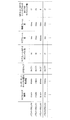
図5は、NRセルにおける送信信号に関するパラメータセットの一例を示す図である。図5の例では、パラメータセットに含まれる送信信号に関するパラメータは、サブキャリア間隔、NRセルにおけるリソースブロックあたりのサブキャリア数、サブフレームあたりのシンボル数、および、CP長タイプである。CP長タイプは、NRセルで用いられるCP長のタイプである。例えば、CP長タイプ1はLTEにおけるノーマルCPに相当し、CP長タイプ2はLTEにおける拡張CPに相当する。
FIG. 5 is a diagram showing an example of a parameter set relating to a transmission signal in the NR cell. In the example of FIG. 5, the parameters related to the transmission signal included in the parameter set are the subcarrier interval, the number of subcarriers per resource block in the NR cell, the number of symbols per subframe, and the CP length type. The CP length type is the type of CP length used in the NR cell. For example,
NRセルにおける送信信号に関するパラメータセットは、下りリンクおよび上りリンクでそれぞれ個別に規定することができる。また、NRセルにおける送信信号に関するパラメータセットは、下りリンクおよび上りリンクでそれぞれ独立に設定できる。 The parameter set for the transmission signal in the NR cell can be specified individually for the downlink and the uplink, respectively. Further, the parameter set related to the transmission signal in the NR cell can be set independently for the downlink and the uplink.
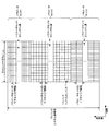
図6は、本実施形態におけるNRの下りリンクサブフレームの一例を示す図である。図6の例では、パラメータセット1、パラメータセット0およびパラメータセット2を用いて生成される信号が、セル(システム帯域幅)において、FDMされる。図6に示される図は、NRの下りリンクリソースグリッドとも呼称される。基地局装置1は、端末装置2への下りリンクサブフレームにおいて、NRの下りリンク物理チャネルおよび/またはNRの下りリンク物理信号を送信できる。端末装置2は、基地局装置1からの下りリンクサブフレームにおいて、NRの下りリンク物理チャネルおよび/またはNRの下りリンク物理信号を受信できる。
FIG. 6 is a diagram showing an example of a downlink subframe of NR in the present embodiment. In the example of FIG. 6, the signals generated using parameter set 1, parameter set 0 and parameter set 2 are FDMed in the cell (system bandwidth). The figure shown in FIG. 6 is also referred to as an NR downlink resource grid. The
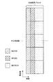
図7は、本実施形態におけるNRの上りリンクサブフレームの一例を示す図である。図7の例では、パラメータセット1、パラメータセット0およびパラメータセット2を用いて生成される信号が、セル(システム帯域幅)において、FDMされる。図7に示される図は、NRの上りリンクリソースグリッドとも呼称される。基地局装置1は、端末装置2への上りリンクサブフレームにおいて、NRの上りリンク物理チャネルおよび/またはNRの上りリンク物理信号を送信できる。端末装置2は、基地局装置1からの上りリンクサブフレームにおいて、NRの上りリンク物理チャネルおよび/またはNRの上りリンク物理信号を受信できる。
FIG. 7 is a diagram showing an example of an uplink subframe of NR in the present embodiment. In the example of FIG. 7, the signals generated using parameter set 1, parameter set 0 and parameter set 2 are FDMed in the cell (system bandwidth). The figure shown in FIG. 7 is also referred to as an NR uplink resource grid. The
<本実施形態におけるアンテナポート>
アンテナポートは、あるシンボルを運ぶ伝搬チャネルが、同一のアンテナポートにおける別のシンボルを運ぶ伝搬チャネルから推測できるようにするために定義される。例えば、同一のアンテナポートにおける異なる物理リソースは、同一の伝搬チャネルで送信されていると想定できる。すなわち、あるアンテナポートにおけるシンボルは、そのアンテナポートにおける参照信号により伝搬チャネルを推定し、復調することができる。また、アンテナポート毎に1つのリソースグリッドがある。アンテナポートは、参照信号によって定義される。また、それぞれの参照信号は、複数のアンテナポートを定義できる。
<Antenna port in this embodiment>
Antenna ports are defined so that a propagation channel carrying one symbol can be inferred from a propagation channel carrying another symbol on the same antenna port. For example, it can be assumed that different physical resources on the same antenna port are transmitted on the same propagation channel. That is, a symbol at an antenna port can be demodulated by estimating the propagation channel from the reference signal at that antenna port. There is also one resource grid for each antenna port. The antenna port is defined by the reference signal. Also, each reference signal can define multiple antenna ports.
アンテナポートはアンテナポート番号によって特定または識別される。例えば、アンテナポート0〜3は、CRSが送信されるアンテナポートである。すなわち、アンテナポート0〜3で送信されるPDSCHは、アンテナポート0〜3に対応するCRSで復調できる。 Antenna ports are identified or identified by antenna port number. For example, antenna ports 0 to 3 are antenna ports to which CRS is transmitted. That is, the PDSCH transmitted through the antenna ports 0 to 3 can be demodulated by the CRS corresponding to the antenna ports 0 to 3.
2つのアンテナポートは所定の条件を満たす場合、準同一位置(QCL:Quasi co-location)であると表すことができる。その所定の条件は、あるアンテナポートにおけるシンボルを運ぶ伝搬チャネルの広域的特性が、別のアンテナポートにおけるシンボルを運ぶ伝搬チャネルから推測できることである。広域的特性は、遅延分散、ドップラースプレッド、ドップラーシフト、平均利得および/または平均遅延を含む。 The two antenna ports can be expressed as having a quasi-co-location (QCL) if a predetermined condition is satisfied. The predetermined condition is that the wide-area characteristics of the propagation channel carrying the symbol at one antenna port can be inferred from the propagation channel carrying the symbol at another antenna port. Wide-area characteristics include delay variance, Doppler spread, Doppler shift, average gain and / or average delay.
本実施形態において、アンテナポート番号は、RAT毎に異なって定義されてもよいし、RAT間で共通に定義されてもよい。例えば、LTEにおけるアンテナポート0〜3は、CRSが送信されるアンテナポートである。NRにおいて、アンテナポート0〜3は、LTEと同様のCRSが送信されるアンテナポートとすることができる。また、NRにおいて、LTEと同様のCRSが送信されるアンテナポートは、アンテナポート0〜3とは異なるアンテナポート番号とすることができる。本実施形態の説明において、所定のアンテナポート番号は、LTEおよび/またはNRに対して適用できる。 In the present embodiment, the antenna port number may be defined differently for each RAT, or may be commonly defined among the RATs. For example, antenna ports 0 to 3 in LTE are antenna ports to which CRS is transmitted. In NR, antenna ports 0 to 3 can be antenna ports to which CRS similar to LTE is transmitted. Further, in NR, the antenna port to which CRS similar to LTE is transmitted may have an antenna port number different from that of antenna ports 0 to 3. In the description of this embodiment, the predetermined antenna port number can be applied to LTE and / or NR.
<本実施形態における物理チャネルおよび物理信号>
本実施形態において、物理チャネルおよび物理信号が用いられる。
<Physical channel and physical signal in this embodiment>
In this embodiment, physical channels and physical signals are used.
物理チャネルは、下りリンク物理チャネル、上りリンク物理チャネルおよびサイドリンク物理チャネルを含む。物理信号は、下りリンク物理信号、上りリンク物理信号およびサイドリンク物理信号を含む。 Physical channels include downlink physical channels, uplink physical channels, and side-link physical channels. Physical signals include downlink physical signals, uplink physical signals and side link physical signals.
LTEにおける物理チャネルおよび物理信号は、それぞれLTE物理チャネルおよびLTE物理信号とも呼称される。NRにおける物理チャネルおよび物理信号は、それぞれNR物理チャネルおよびNR物理信号とも呼称される。LTE物理チャネルおよびNR物理チャネルは、それぞれ異なる物理チャネルとして定義できる。LTE物理信号およびNR物理信号は、それぞれ異なる物理信号として定義できる。本実施形態の説明において、LTE物理チャネルおよびNR物理チャネルは単に物理チャネルとも呼称され、LTE物理信号およびNR物理信号は単に物理信号とも呼称される。すなわち、物理チャネルに対する説明は、LTE物理チャネルおよびNR物理チャネルのいずれに対しても適用できる。物理信号に対する説明は、LTE物理信号およびNR物理信号のいずれに対しても適用できる。 Physical channels and physical signals in LTE are also referred to as LTE physical channels and LTE physical signals, respectively. The physical channel and physical signal in NR are also referred to as NR physical channel and NR physical signal, respectively. The LTE physical channel and the NR physical channel can be defined as different physical channels. The LTE physical signal and the NR physical signal can be defined as different physical signals. In the description of this embodiment, the LTE physical channel and the NR physical channel are also referred to simply as physical channels, and the LTE physical signal and the NR physical signal are also simply referred to as physical signals. That is, the description for physical channels can be applied to both LTE and NR physical channels. The description for physical signals can be applied to both LTE and NR physical signals.
<本実施形態における下りリンク物理チャネル>
PBCHは、基地局装置1のサービングセルに固有の報知情報であるMIB(Master Information Block)を報知するために用いられる。PBCHは無線フレーム内のサブフレーム0のみで送信される。MIBは、40ms間隔で更新できる。PBCHは10ms周期で繰り返し送信される。具体的には、SFN(System Frame Number)を4で割った余りが0である条件を満たす無線フレームにおけるサブフレーム0においてMIBの初期送信が行なわれ、他の全ての無線フレームにおけるサブフレーム0においてMIBの再送信(repetition)が行われる。SFNは無線フレームの番号(システムフレーム番号)である。MIBはシステム情報である。例えば、MIBは、SFNを示す情報を含む。
<Downlink physical channel in this embodiment>
The PBCH is used to notify the MIB (Master Information Block), which is the notification information unique to the serving cell of the
PCFICHは、PDCCHの送信に用いられるOFDMシンボルの数に関する情報を送信するために用いられる。PCFICHで示される領域は、PDCCH領域とも呼称される。PCFICHで送信される情報は、CFI(Control Format Indicator)とも呼称される。 PCFICH is used to transmit information about the number of OFDM symbols used to transmit PDCCH. The region represented by PCFICH is also referred to as a PDCCH region. The information transmitted by PCFICH is also referred to as CFI (Control Format Indicator).
PDCCHおよびEPDCCHは、下りリンク制御情報(Downlink Control Information: DCI)を送信するために用いられる。下りリンク制御情報の情報ビットのマッピングが、DCIフォーマットとして定義される。下りリンク制御情報は、下りリンクグラント(downlink grant)および上りリンクグラント(uplink grant)を含む。下りリンクグラントは、下りリンクアサインメント(downlink assignment)または下りリンク割り当て(downlink allocation)とも称する。 PDCCH and EPDCCH are used to transmit Downlink Control Information (DCI). The mapping of the information bits of the downlink control information is defined as the DCI format. The downlink control information includes a downlink grant and an uplink grant. Downlink grants are also referred to as downlink assignments or downlink allocations.
PDCCHは、連続する1つまたは複数のCCE(Control Channel Element)の集合によって送信される。CCEは、9つのREG(Resource Element Group)で構成される。REGは、4つのリソースエレメントで構成される。PDCCHがn個の連続するCCEで構成される場合、そのPDCCHは、CCEのインデックス(番号)であるiをnで割った余りが0である条件を満たすCCEから始まる。 The PDCCH is transmitted by a set of one or more consecutive CCEs (Control Channel Elements). CCE is composed of 9 REGs (Resource Element Groups). The REG is composed of four resource elements. When the PDCCH is composed of n consecutive CCEs, the PDCCH starts from the CCE satisfying the condition that the remainder of dividing i, which is the index (number) of the CCE, by n is 0.
EPDCCHは、連続する1つまたは複数のECCE(Enhanced Control Channel Element)の集合によって送信される。ECCEは、複数のEREG(Enhanced Resource Element Group)で構成される。 The EPDCCH is transmitted by a set of one or more consecutive ECCEs (Enhanced Control Channel Elements). ECCE is composed of a plurality of EREGs (Enhanced Resource Element Groups).
下りリンクグラントは、あるセル内のPDSCHのスケジューリングに用いられる。下りリンクグラントは、その下りリンクグラントが送信されたサブフレームと同じサブフレーム内のPDSCHのスケジューリングに用いられる。上りリンクグラントは、あるセル内のPUSCHのスケジューリングに用いられる。上りリンクグラントは、その上りリンクグラントが送信されたサブフレームより4つ以上後のサブフレーム内の単一のPUSCHのスケジューリングに用いられる。 The downlink grant is used for scheduling PDSCH in a cell. The downlink grant is used to schedule the PDSCH in the same subframe as the subframe in which the downlink grant was transmitted. Uplink grants are used to schedule PUSCH within a cell. The uplink grant is used to schedule a single PUSCH in a subframe four or more later than the subframe in which the uplink grant was transmitted.
DCIには、CRC(Cyclic Redundancy Check)パリティビットが付加される。CRCパリティビットは、RNTI(Radio Network Temporary Identifier)でスクランブルされる。RNTIは、DCIの目的などに応じて、規定または設定できる識別子である。RNTIは、仕様で予め規定される識別子、セルに固有の情報として設定される識別子、端末装置2に固有の情報として設定される識別子、または、端末装置2に属するグループに固有の情報として設定される識別子である。例えば、端末装置2は、PDCCHまたはEPDCCHのモニタリングにおいて、DCIに付加されたCRCパリティビットに所定のRNTIでデスクランブルし、CRCが正しいかどうかを識別する。CRCが正しい場合、そのDCIは端末装置2のためのDCIであることが分かる。
A CRC (Cyclic Redundancy Check) parity bit is added to the DCI. The CRC parity bit is scrambled by RNTI (Radio Network Temporary Identifier). RNTI is an identifier that can be specified or set according to the purpose of DCI and the like. RNTI is set as an identifier defined in advance in the specifications, an identifier set as cell-specific information, an identifier set as terminal device 2-specific information, or information unique to a group belonging to the
PDSCHは、下りリンクデータ(Downlink Shared Channel: DL-SCH)を送信するために用いられる。また、PDSCHは、上位層の制御情報を送信するためにも用いられる。 The PDSCH is used to transmit downlink data (Downlink Shared Channel: DL-SCH). The PDSCH is also used to transmit control information of the upper layer.
PDCCH領域において、複数のPDCCHが周波数、時間、および/または、空間多重されてもよい。EPDCCH領域において、複数のEPDCCHが周波数、時間、および/または、空間多重されてもよい。PDSCH領域において、複数のPDSCHが周波数、時間、および/または、空間多重されてもよい。PDCCH、PDSCHおよび/またはEPDCCHは周波数、時間、および/または、空間多重されてもよい。 In the PDCCH region, multiple PDCCHs may be frequency, temporal, and / or spatially multiplexed. In the EPDCCH region, multiple EPDCCHs may be frequency, temporal, and / or spatially multiplexed. In the PDSCH region, multiple PDSCHs may be frequency, temporal, and / or spatially multiplexed. PDCCH, PDSCH and / or EPDCCH may be frequency, temporal, and / or spatially multiplexed.
<本実施形態における下りリンク物理信号>
同期信号は、端末装置2が下りリンクの周波数領域および/または時間領域の同期をとるために用いられる。同期信号は、PSS(Primary Synchronization Signal)およびSSS(Secondary Synchronization Signal)を含む。同期信号は無線フレーム内の所定のサブフレームに配置される。例えば、TDD方式において、同期信号は無線フレーム内のサブフレーム0、1、5、および6に配置される。FDD方式において、同期信号は無線フレーム内のサブフレーム0および5に配置される。
<Downlink physical signal in this embodiment>
The synchronization signal is used by the
PSSは、粗いフレーム/シンボルタイミング同期(時間領域の同期)やセル識別グループの識別に用いられてもよい。SSSは、より正確なフレームタイミング同期やセルの識別、CP長の検出に用いられてもよい。つまり、PSSとSSSを用いることによって、フレームタイミング同期とセル識別を行うことができる。 PSS may be used for coarse frame / symbol timing synchronization (time domain synchronization) and cell identification group identification. SSS may be used for more accurate frame timing synchronization, cell identification, and CP length detection. That is, by using PSS and SSS, frame timing synchronization and cell identification can be performed.
下りリンク参照信号は、端末装置2が下りリンク物理チャネルの伝搬路推定、伝搬路補正、下りリンクのCSI(Channel State Information、チャネル状態情報)の算出、および/または、端末装置2のポジショニングの測定を行うために用いられる。
For the downlink reference signal, the
CRSは、サブフレームの全帯域で送信される。CRSは、PBCH、PDCCH、PHICH、PCFICH、およびPDSCHの受信(復調)を行うために用いられる。CRSは、端末装置2が下りリンクのチャネル状態情報を算出するために用いられてもよい。PBCH、PDCCH、PHICH、およびPCFICHは、CRSの送信に用いられるアンテナポートで送信される。CRSは、1、2または4のアンテナポートの構成をサポートする。CRSは、アンテナポート0〜3の1つまたは複数で送信される。
The CRS is transmitted over the entire band of the subframe. CRS is used to receive (demodulate) PBCH, PDCCH, PHICH, PCFICH, and PDSCH. The CRS may be used by the
PDSCHに関連するURSは、URSが関連するPDSCHの送信に用いられるサブフレームおよび帯域で送信される。URSは、URSが関連するPDSCHの復調を行なうために用いられる。PDSCHに関連するURSは、アンテナポート5、7〜14の1つまたは複数で送信される。
The URS associated with the PDSCH is transmitted in the subframes and bands used by the URS to transmit the associated PDSCH. URS is used to demodulate the PDSCH associated with URS. URS associated with PDSCH is transmitted on one or more of
PDSCHは、送信モードおよびDCIフォーマットに基づいて、CRSまたはURSの送信に用いられるアンテナポートで送信される。DCIフォーマット1Aは、CRSの送信に用いられるアンテナポートで送信されるPDSCHのスケジューリングに用いられる。DCIフォーマット2Dは、URSの送信に用いられるアンテナポートで送信されるPDSCHのスケジューリングに用いられる。 The PDSCH is transmitted on the antenna port used for CRS or URS transmission based on the transmission mode and DCI format. DCI format 1A is used for scheduling PDSCH transmitted at the antenna port used for CRS transmission. DCI format 2D is used for scheduling PDSCH transmitted at the antenna port used for URS transmission.
EPDCCHに関連するDMRSは、DMRSが関連するEPDCCHの送信に用いられるサブフレームおよび帯域で送信される。DMRSは、DMRSが関連するEPDCCHの復調を行なうために用いられる。EPDCCHは、DMRSの送信に用いられるアンテナポートで送信される。EPDCCHに関連するDMRSは、アンテナポート107〜114の1つまたは複数で送信される。 The EPDCCH-related DMRS is transmitted in the subframes and bands used to transmit the EPDCCH associated with the DMRS. DMRS is used to demodulate the EPDCCH associated with DMRS. The EPDCCH is transmitted on the antenna port used to transmit the DMRS. The DMRS associated with EPDCCH is transmitted on one or more of antenna ports 107-114.
CSI−RSは、設定されたサブフレームで送信される。CSI−RSが送信されるリソースは、基地局装置1によって設定される。CSI−RSは、端末装置2が下りリンクのチャネル状態情報を算出するために用いられる。端末装置2は、CSI−RSを用いて信号測定(チャネル測定)を行う。CSI−RSは、1、2、4、8、12、16、24および32の一部または全部のアンテナポートの設定をサポートする。CSI−RSは、アンテナポート15〜46の1つまたは複数で送信される。なお、サポートされるアンテナポートは、端末装置2の端末装置ケイパビリティ、RRCパラメータの設定、および/または設定される送信モードなどに基づいて決定されてもよい。
CSI-RS is transmitted in the set subframe. The resource to which the CSI-RS is transmitted is set by the
ZP CSI−RSのリソースは、上位層によって設定される。ZP CSI−RSのリソースはゼロ出力の電力で送信されてもよい。すなわち、ZP CSI−RSのリソースは何も送信しなくてもよい。ZP CSI−RSの設定したリソースにおいて、PDSCHおよびEPDCCHは送信されない。例えば、ZP CSI−RSのリソースは隣接セルがNZP CSI−RSの送信を行うために用いられる。また、例えば、ZP CSI−RSのリソースはCSI−IMを測定するために用いられる。また、例えば、ZP CSI−RSのリソースはPDSCHなどの所定のチャネルが送信されないリソースである。換言すると、所定のチャネルは、ZP CSI−RSのリソースを除いて(レートマッチングして、パンクチャして)マッピングされる。 The resources of ZP CSI-RS are set by the upper layer. ZP CSI-RS resources may be transmitted with zero output power. That is, the ZP CSI-RS resource does not have to be transmitted. PDSCH and EPDCCH are not transmitted in the resource set by ZP CSI-RS. For example, the ZP CSI-RS resource is used by neighboring cells to transmit the NZP CSI-RS. Also, for example, the resources of ZP CSI-RS are used to measure CSI-IM. Further, for example, the resource of ZP CSI-RS is a resource such as PDSCH in which a predetermined channel is not transmitted. In other words, a given channel is mapped (rate-matched and punctured) except for the ZP CSI-RS resources.
<本実施形態における上りリンク物理チャネル>
PUCCHは、上りリンク制御情報(Uplink Control Information: UCI)を送信するために用いられる物理チャネルである。上りリンク制御情報は、下りリンクのチャネル状態情報(Channel State Information: CSI)、PUSCHリソースの要求を示すスケジューリング要求(Scheduling Request: SR)、下りリンクデータ(Transport block: TB, Downlink-Shared Channel: DL-SCH)に対するHARQ−ACKを含む。HARQ−ACKは、ACK/NACK、HARQフィードバック、または、応答情報とも称される。また、下りリンクデータに対するHARQ−ACKは、ACK、NACK、またはDTXを示す。
<Uplink physical channel in this embodiment>
The PUCCH is a physical channel used to transmit Uplink Control Information (UCI). The uplink control information includes downlink channel state information (CSI), scheduling request indicating a PUSCH resource request (SR), and downlink data (Transport block: TB, Downlink-Shared Channel: DL). -Includes HARQ-ACK for SCH). HARQ-ACK is also referred to as ACK / NACK, HARQ feedback, or response information. Further, HARQ-ACK for downlink data indicates ACK, NACK, or DTX.
PUSCHは、上りリンクデータ(Uplink-Shared Channel: UL-SCH)を送信するために用いられる物理チャネルである。また、PUSCHは、上りリンクデータと共にHARQ−ACKおよび/またはチャネル状態情報を送信するために用いられてもよい。また、PUSCHは、チャネル状態情報のみ、または、HARQ−ACKおよびチャネル状態情報のみを送信するために用いられてもよい。 The PUSCH is a physical channel used for transmitting uplink data (Uplink-Shared Channel: UL-SCH). The PUSCH may also be used to transmit HARQ-ACK and / or channel state information along with uplink data. In addition, PUSCH may be used to transmit only channel state information, or only HARQ-ACK and channel state information.
PRACHは、ランダムアクセスプリアンブルを送信するために用いられる物理チャネルである。PRACHは、端末装置2が基地局装置1と時間領域の同期をとるために用いられることができる。また、PRACHは、初期コネクション構築(initial connection establishment)手続き(処理)、ハンドオーバ手続き、コネクション再構築(connection re-establishment)手続き、上りリンク送信に対する同期(タイミング調整)、および/または、PUSCHリソースの要求を示すためにも用いられる。
The PRACH is a physical channel used to transmit a random access preamble. The PRACH can be used by the
PUCCH領域において、複数のPUCCHが周波数、時間、空間および/またはコード多重される。PUSCH領域において、複数のPUSCHが周波数、時間、空間および/またはコード多重されてもよい。PUCCHおよびPUSCHは周波数、時間、空間および/またはコード多重されてもよい。PRACHは単一のサブフレームまたは2つのサブフレームにわたって配置されてもよい。複数のPRACHが符号多重されてもよい。 In the PUCCH region, multiple PUCCHs are frequency, temporal, spatial and / or code-multiplexed. In the PUSCH region, multiple PUSCHs may be frequency, time, spatial and / or code-multiplexed. PUCCH and PUSCH may be frequency, temporal, spatial and / or code-multiplexed. The PRACH may be spread over a single subframe or two subframes. A plurality of PRACHs may be code-multiplexed.
<本実施形態における上りリンク物理信号>
UL−DMRSは、PUSCHまたはPUCCHの送信に関連する。UL−DMRSは、PUSCHまたはPUCCHと時間多重される。基地局装置1は、PUSCHまたはPUCCHの伝搬路補正を行うためにUL−DMRSを用いてもよい。本実施形態の説明において、PUSCHの送信は、PUSCHとUL−DMRSを多重して送信することも含む。本実施形態の説明において、PUCCHの送信は、PUCCHとUL−DMRSを多重して送信することも含む。
<Uplink physical signal in this embodiment>
UL-DMRS is associated with the transmission of PUSCH or PUCCH. UL-DMRS is time-multiplexed with PUSCH or PUCCH. The
SRSは、PUSCHまたはPUCCHの送信に関連しない。基地局装置1は、上りリンクのチャネル状態を測定するためにSRSを用いてもよい。
SRS is not associated with the transmission of PUSCH or PUCCH. The
SRSは上りリンクサブフレーム内の最後のシンボルを用いて送信される。つまり、SRSは上りリンクサブフレーム内の最後のシンボルに配置される。端末装置2は、あるセルのあるシンボルにおいて、SRSと、PUCCH、PUSCHおよび/またはPRACHとの同時送信を制限できる。端末装置2は、あるセルのある上りリンクサブフレームにおいて、その上りリンクサブフレーム内の最後のシンボルを除くシンボルを用いてPUSCHおよび/またはPUCCHを送信し、その上りリンクサブフレーム内の最後のシンボルを用いてSRSを送信することができる。つまり、あるセルのある上りリンクサブフレームにおいて、端末装置2は、SRSと、PUSCHおよびPUCCHと、を送信することができる。
The SRS is transmitted using the last symbol in the uplink subframe. That is, the SRS is placed at the last symbol in the uplink subframe. The
SRSにおいて、トリガータイプの異なるSRSとして、トリガータイプ0SRSおよびトリガータイプ1SRSが定義される。トリガータイプ0SRSは、上位層シグナリングによって、トリガータイプ0SRSに関するパラメータが設定される場合に送信される。トリガータイプ1SRSは、上位層シグナリングによって、トリガータイプ1SRSに関するパラメータが設定され、DCIフォーマット0、1A、2B、2C、2D、または4に含まれるSRSリクエストによって送信が要求された場合に送信される。なお、SRSリクエストは、DCIフォーマット0、1A、または4についてはFDDとTDDの両方に含まれ、DCIフォーマット2B、2C、または2DについてはTDDにのみ含まれる。同じサービングセルの同じサブフレームでトリガータイプ0SRSの送信とトリガータイプ1SRSの送信が生じる場合、トリガータイプ1SRSの送信が優先される。トリガータイプ0SRSは、周期的SRSとも呼称される。トリガータイプ1SRSは、非周期的SRSとも呼称される。
In SRS, trigger type 0SRS and trigger type 1SRS are defined as SRS having different trigger types. Trigger type 0SRS is transmitted when parameters related to trigger type 0SRS are set by upper layer signaling. The trigger type 1SRS is transmitted when the parameters related to the trigger type 1SRS are set by the upper layer signaling and the transmission is requested by the SRS request included in the
<本実施形態における基地局装置1の構成例>
図8は、本実施形態の基地局装置1の構成を示す概略ブロック図である。図示するように、基地局装置1は、上位層処理部101、制御部103、受信部105、送信部107、および、送受信アンテナ109、を含んで構成される。また、受信部105は、復号化部1051、復調部1053、多重分離部1055、無線受信部1057、およびチャネル測定部1059を含んで構成される。また、送信部107は、符号化部1071、変調部1073、多重部1075、無線送信部1077、および下りリンク参照信号生成部1079を含んで構成される。
<Structure example of
FIG. 8 is a schematic block diagram showing the configuration of the
既に説明したように、基地局装置1は、1つ以上のRATをサポートできる。図8に示す基地局装置1に含まれる各部の一部または全部は、RATに応じて個別に構成されうる。例えば、受信部105および送信部107は、LTEとNRとで個別に構成される。また、NRセルにおいて、図8に示す基地局装置1に含まれる各部の一部または全部は、送信信号に関するパラメータセットに応じて個別に構成されうる。例えば、あるNRセルにおいて、無線受信部1057および無線送信部1077は、送信信号に関するパラメータセットに応じて個別に構成されうる。
As described above, the
上位層処理部101は、媒体アクセス制御(MAC: Medium Access Control)層、パケットデータ統合プロトコル(Packet Data Convergence Protocol: PDCP)層、無線リンク制御(Radio Link Control: RLC)層、無線リソース制御(Radio Resource Control: RRC)層の処理を行う。また、上位層処理部101は、受信部105、および送信部107の制御を行うために制御情報を生成し、制御部103に出力する。
The upper
制御部103は、上位層処理部101からの制御情報に基づいて、受信部105および送信部107の制御を行う。制御部103は、上位層処理部101への制御情報を生成し、上位層処理部101に出力する。制御部103は、復号化部1051からの復号化された信号およびチャネル測定部1059からのチャネル推定結果を入力する。制御部103は、符号化する信号を符号化部1071へ出力する。また、制御部103は、基地局装置1の全体または一部を制御するために用いられる。
The
上位層処理部101は、RAT制御、無線リソース制御、サブフレーム設定、スケジューリング制御、および/または、CSI報告制御に関する処理および管理を行う。上位層処理部101における処理および管理は、端末装置毎、または基地局装置に接続している端末装置共通に行われる。上位層処理部101における処理および管理は、上位層処理部101のみで行われてもよいし、上位ノードまたは他の基地局装置から取得してもよい。また、上位層処理部101における処理および管理は、RATに応じて個別に行われてもよい。例えば、上位層処理部101は、LTEにおける処理および管理と、NRにおける処理および管理とを個別に行う。
The upper
上位層処理部101におけるRAT制御では、RATに関する管理が行われる。例えば、RAT制御では、LTEに関する管理および/またはNRに関する管理が行われる。NRに関する管理は、NRセルにおける送信信号に関するパラメータセットの設定および処理を含む。
In the RAT control in the upper
上位層処理部101における無線リソース制御では、下りリンクデータ(トランスポートブロック)、システムインフォメーション、RRCメッセージ(RRCパラメータ)、および/または、MAC制御エレメント(CE:Control Element)の生成および/または管理が行われる。
In the radio resource control in the upper
上位層処理部101におけるサブフレーム設定では、サブフレーム設定、サブフレームパターン設定、上りリンク−下りリンク設定、上りリンク参照UL−DL設定、および/または、下りリンク参照UL−DL設定の管理が行われる。なお、上位層処理部101におけるサブフレーム設定は、基地局サブフレーム設定とも呼称される。また、上位層処理部101におけるサブフレーム設定は、上りリンクのトラフィック量および下りリンクのトラフィック量に基づいて決定できる。また、上位層処理部101におけるサブフレーム設定は、上位層処理部101におけるスケジューリング制御のスケジューリング結果に基づいて決定できる。
In the subframe setting in the upper
上位層処理部101におけるスケジューリング制御では、受信したチャネル状態情報およびチャネル測定部1059から入力された伝搬路の推定値やチャネルの品質などに基づいて、物理チャネルを割り当てる周波数およびサブフレーム、物理チャネルの符号化率および変調方式および送信電力などが決定される。例えば、制御部103は、上位層処理部101におけるスケジューリング制御のスケジューリング結果に基づいて、制御情報(DCIフォーマット)を生成する。
In the scheduling control in the upper
上位層処理部101におけるCSI報告制御では、端末装置2のCSI報告が制御される。例えば、端末装置2においてCSIを算出するために想定するためのCSI参照リソースに関する設定が制御される。
In the CSI report control in the upper
受信部105は、制御部103からの制御に従って、送受信アンテナ109を介して端末装置2から送信された信号を受信し、さらに分離、復調、復号などの受信処理を行い、受信処理された情報を制御部103に出力する。なお、受信部105における受信処理は、あらかじめ規定された設定、または基地局装置1が端末装置2に通知した設定に基づいて行われる。
The receiving
無線受信部1057は、送受信アンテナ109を介して受信された上りリンクの信号に対して、中間周波数への変換(ダウンコンバート)、不要な周波数成分の除去、信号レベルが適切に維持されるように増幅レベルの制御、受信された信号の同相成分および直交成分に基づく直交復調、アナログ信号からデジタル信号への変換、ガードインターバル(Guard Interval: GI)の除去、および/または、高速フーリエ変換(Fast Fourier Transform: FFT)による周波数領域信号の抽出を行う。
The radio receiver 1057 converts the uplink signal received via the transmission /
多重分離部1055は、無線受信部1057から入力された信号から、PUCCHまたはPUSCHなどの上りリンクチャネルおよび/または上りリンク参照信号を分離する。多重分離部1055は、上りリンク参照信号をチャネル測定部1059に出力する。多重分離部1055は、チャネル測定部1059から入力された伝搬路の推定値から、上りリンクチャネルに対する伝搬路の補償を行う。
The
復調部1053は、上りリンクチャネルの変調シンボルに対して、BPSK(Binary Phase Shift Keying)、QPSK(Quadrature Phase shift Keying)、16QAM(Quadrature Amplitude Modulation)、64QAM、256QAM等の変調方式を用いて受信信号の復調を行う。復調部1053は、MIMO多重された上りリンクチャネルの分離および復調を行う。
The
復号化部1051は、復調された上りリンクチャネルの符号化ビットに対して、復号処理を行う。復号された上りリンクデータおよび/または上りリンク制御情報は制御部103へ出力される。復号化部1051は、PUSCHに対しては、トランスポートブロック毎に復号処理を行う。
The
チャネル測定部1059は、多重分離部1055から入力された上りリンク参照信号から伝搬路の推定値および/またはチャネルの品質などを測定し、多重分離部1055および/または制御部103に出力する。例えば、チャネル測定部1059は、UL−DMRSを用いてPUCCHまたはPUSCHに対する伝搬路補償を行うための伝搬路の推定値を測定し、SRSを用いて上りリンクにおけるチャネルの品質を測定する。
The
送信部107は、制御部103からの制御に従って、上位層処理部101から入力された下りリンク制御情報および下りリンクデータに対して、符号化、変調および多重などの送信処理を行う。例えば、送信部107は、PHICH、PDCCH、EPDCCH、PDSCH、および下りリンク参照信号を生成および多重し、送信信号を生成する。なお、送信部107における送信処理は、あらかじめ規定された設定、基地局装置1が端末装置2に通知した設定、または、同一のサブフレームで送信されるPDCCHまたはEPDCCHを通じて通知される設定に基づいて行われる。
The
符号化部1071は、制御部103から入力されたHARQインディケータ(HARQ−ACK)、下りリンク制御情報、および下りリンクデータを、ブロック符号化、畳込み符号化、ターボ符号化等の所定の符号化方式を用いて符号化を行う。変調部1073は、符号化部1071から入力された符号化ビットをBPSK、QPSK、16QAM、64QAM、256QAM等の所定の変調方式で変調する。下りリンク参照信号生成部1079は、物理セル識別子(PCI:Physical cell identification)、端末装置2に設定されたRRCパラメータなどに基づいて、下りリンク参照信号を生成する。多重部1075は、各チャネルの変調シンボルと下りリンク参照信号を多重し、所定のリソースエレメントに配置する。
The
無線送信部1077は、多重部1075からの信号に対して、逆高速フーリエ変換(Inverse Fast Fourier Transform: IFFT)による時間領域の信号への変換、ガードインターバルの付加、ベースバンドのデジタル信号の生成、アナログ信号への変換、直交変調、中間周波数の信号から高周波数の信号への変換(アップコンバート: up convert)、余分な周波数成分の除去、電力の増幅などの処理を行い、送信信号を生成する。無線送信部1077が出力した送信信号は、送受信アンテナ109から送信される。
The
なお、本実施形態に係る基地局装置1の送信処理部は、送信部107、制御部103又は上位層処理部101の少なくともいずれかに相当し得る。また、本実施形態に係る基地局装置1の受信処理部は、受信部105、制御部103又は上位層処理部101の少なくともいずれかに相当し得る。
The transmission processing unit of the
<本実施形態における端末装置2の構成例>
図9は、本実施形態の端末装置2の構成を示す概略ブロック図である。図示するように、端末装置2は、上位層処理部201、制御部203、受信部205、送信部207、および送受信アンテナ209を含んで構成される。また、受信部205は、復号化部2051、復調部2053、多重分離部2055、無線受信部2057、およびチャネル測定部2059を含んで構成される。また、送信部207は、符号化部2071、変調部2073、多重部2075、無線送信部2077、および上りリンク参照信号生成部2079を含んで構成される。
<Structure example of
FIG. 9 is a schematic block diagram showing the configuration of the
既に説明したように、端末装置2は、1つ以上のRATをサポートできる。図9に示す端末装置2に含まれる各部の一部または全部は、RATに応じて個別に構成されうる。例えば、受信部205および送信部207は、LTEとNRとで個別に構成される。また、NRセルにおいて、図9に示す端末装置2に含まれる各部の一部または全部は、送信信号に関するパラメータセットに応じて個別に構成されうる。例えば、あるNRセルにおいて、無線受信部2057および無線送信部2077は、送信信号に関するパラメータセットに応じて個別に構成されうる。
As described above, the
上位層処理部201は、上りリンクデータ(トランスポートブロック)を、制御部203に出力する。上位層処理部201は、媒体アクセス制御(MAC: Medium Access Control)層、パケットデータ統合プロトコル(Packet Data Convergence Protocol: PDCP)層、無線リンク制御(Radio Link Control: RLC)層、無線リソース制御(Radio Resource Control: RRC)層の処理を行なう。また、上位層処理部201は、受信部205、および送信部207の制御を行うために制御情報を生成し、制御部203に出力する。
The upper
制御部203は、上位層処理部201からの制御情報に基づいて、受信部205および送信部207の制御を行う。制御部203は、上位層処理部201への制御情報を生成し、上位層処理部201に出力する。制御部203は、復号化部2051からの復号化された信号およびチャネル測定部2059からのチャネル推定結果を入力する。制御部203は、符号化する信号を符号化部2071へ出力する。また、制御部203は、端末装置2の全体または一部を制御するために用いられてもよい。
The
上位層処理部201は、RAT制御、無線リソース制御、サブフレーム設定、スケジューリング制御、および/または、CSI報告制御に関する処理および管理を行う。上位層処理部201における処理および管理は、あらかじめ規定される設定、および/または、基地局装置1から設定または通知される制御情報に基づく設定に基づいて行われる。例えば、基地局装置1からの制御情報は、RRCパラメータ、MAC制御エレメントまたはDCIを含む。また、上位層処理部201における処理および管理は、RATに応じて個別に行われてもよい。例えば、上位層処理部201は、LTEにおける処理および管理と、NRにおける処理および管理とを個別に行う。
The upper
上位層処理部201におけるRAT制御では、RATに関する管理が行われる。例えば、RAT制御では、LTEに関する管理および/またはNRに関する管理が行われる。NRに関する管理は、NRセルにおける送信信号に関するパラメータセットの設定および処理を含む。
In the RAT control in the upper
上位層処理部201における無線リソース制御では、自装置における設定情報の管理が行われる。上位層処理部201における無線リソース制御では、上りリンクデータ(トランスポートブロック)、システムインフォメーション、RRCメッセージ(RRCパラメータ)、および/または、MAC制御エレメント(CE:Control Element)の生成および/または管理が行われる。
In the radio resource control in the upper
上位層処理部201におけるサブフレーム設定では、基地局装置1および/または基地局装置1とは異なる基地局装置におけるサブフレーム設定が管理される。サブフレーム設定は、サブフレームに対する上りリンクまたは下りリンクの設定、サブフレームパターン設定、上りリンク−下りリンク設定、上りリンク参照UL−DL設定、および/または、下りリンク参照UL−DL設定を含む。なお、上位層処理部201におけるサブフレーム設定は、端末サブフレーム設定とも呼称される。
In the subframe setting in the upper
上位層処理部201におけるスケジューリング制御では、基地局装置1からのDCI(スケジューリング情報)に基づいて、受信部205および送信部207に対するスケジューリングに関する制御を行うための制御情報が生成される。
In the scheduling control in the upper
上位層処理部201におけるCSI報告制御では、基地局装置1に対するCSIの報告に関する制御が行われる。例えば、CSI報告制御では、チャネル測定部2059でCSIを算出するために想定するためのCSI参照リソースに関する設定が制御される。CSI報告制御では、DCIおよび/またはRRCパラメータに基づいて、CSIを報告するために用いられるリソース(タイミング)を制御する。
In the CSI report control in the upper
受信部205は、制御部203からの制御に従って、送受信アンテナ209を介して基地局装置1から送信された信号を受信し、さらに分離、復調、復号などの受信処理を行い、受信処理された情報を制御部203に出力する。なお、受信部205における受信処理は、あらかじめ規定された設定、または基地局装置1からの通知または設定に基づいて行われる。
The receiving
無線受信部2057は、送受信アンテナ209を介して受信された上りリンクの信号に対して、中間周波数への変換(ダウンコンバート)、不要な周波数成分の除去、信号レベルが適切に維持されるように増幅レベルの制御、受信された信号の同相成分および直交成分に基づく直交復調、アナログ信号からデジタル信号への変換、ガードインターバル(Guard Interval: GI)の除去、および/または、高速フーリエ変換(Fast Fourier Transform: FFT)による周波数領域の信号の抽出を行う。
The radio receiver 2057 converts the uplink signal received via the transmission /
多重分離部2055は、無線受信部2057から入力された信号から、PHICH、PDCCH、EPDCCHまたはPDSCHなどの下りリンクチャネル、下りリンク同期信号および/または下りリンク参照信号を分離する。多重分離部2055は、下りリンク参照信号をチャネル測定部2059に出力する。多重分離部2055は、チャネル測定部2059から入力された伝搬路の推定値から、下りリンクチャネルに対する伝搬路の補償を行う。
The
復調部2053は、下りリンクチャネルの変調シンボルに対して、BPSK、QPSK、16QAM、64QAM、256QAM等の変調方式を用いて受信信号の復調を行う。復調部2053は、MIMO多重された下りリンクチャネルの分離および復調を行う。
The
復号化部2051は、復調された下りリンクチャネルの符号化ビットに対して、復号処理を行う。復号された下りリンクデータおよび/または下りリンク制御情報は制御部203へ出力される。復号化部2051は、PDSCHに対しては、トランスポートブロック毎に復号処理を行う。
The
チャネル測定部2059は、多重分離部2055から入力された下りリンク参照信号から伝搬路の推定値および/またはチャネルの品質などを測定し、多重分離部2055および/または制御部203に出力する。チャネル測定部2059が測定に用いる下りリンク参照信号は、少なくともRRCパラメータによって設定される送信モードおよび/または他のRRCパラメータに基づいて決定されてもよい。例えば、DL−DMRSはPDSCHまたはEPDCCHに対する伝搬路補償を行うための伝搬路の推定値を測定する。CRSはPDCCHまたはPDSCHに対する伝搬路補償を行うための伝搬路の推定値、および/または、CSIを報告するための下りリンクにおけるチャネルを測定する。CSI−RSは、CSIを報告するための下りリンクにおけるチャネルを測定する。チャネル測定部2059は、CRS、CSI−RSまたは検出信号に基づいて、RSRP(Reference Signal Received Power)および/またはRSRQ(Reference Signal Received Quality)を算出し、上位層処理部201へ出力する。
The
送信部207は、制御部203からの制御に従って、上位層処理部201から入力された上りリンク制御情報および上りリンクデータに対して、符号化、変調および多重などの送信処理を行う。例えば、送信部207は、PUSCHまたはPUCCHなどの上りリンクチャネルおよび/または上りリンク参照信号を生成および多重し、送信信号を生成する。なお、送信部207における送信処理は、あらかじめ規定された設定、または、基地局装置1から設定または通知に基づいて行われる。
The
符号化部2071は、制御部203から入力されたHARQインディケータ(HARQ−ACK)、上りリンク制御情報、および上りリンクデータを、ブロック符号化、畳込み符号化、ターボ符号化等の所定の符号化方式を用いて符号化を行う。変調部2073は、符号化部2071から入力された符号化ビットをBPSK、QPSK、16QAM、64QAM、256QAM等の所定の変調方式で変調する。上りリンク参照信号生成部2079は、端末装置2に設定されたRRCパラメータなどに基づいて、上りリンク参照信号を生成する。多重部2075は、各チャネルの変調シンボルと上りリンク参照信号を多重し、所定のリソースエレメントに配置する。
The
無線送信部2077は、多重部2075からの信号に対して、逆高速フーリエ変換(Inverse Fast Fourier Transform: IFFT)による時間領域の信号への変換、ガードインターバルの付加、ベースバンドのデジタル信号の生成、アナログ信号への変換、直交変調、中間周波数の信号から高周波数の信号への変換(アップコンバート: up convert)、余分な周波数成分の除去、電力の増幅などの処理を行い、送信信号を生成する。無線送信部2077が出力した送信信号は、送受信アンテナ209から送信される。
The
なお、本実施形態に係る端末装置2の送信処理部は、送信部207、制御部203又は上位層処理部201の少なくともいずれかに相当し得る。また、本実施形態に係る端末装置2の受信処理部は、受信部205、制御部203又は上位層処理部201の少なくともいずれかに相当し得る。
The transmission processing unit of the
<本実施形態における制御情報のシグナリング>
基地局装置1および端末装置2は、それぞれ制御情報のシグナリング(通知、報知、設定)のために、様々な方法を用いることができる。制御情報のシグナリングは、様々な層(レイヤー)で行うことができる。制御情報のシグナリングは、物理層(レイヤー)を通じたシグナリングである物理層シグナリング、RRC層を通じたシグナリングであるRRCシグナリング、および、MAC層を通じたシグナリングであるMACシグナリングなどを含む。RRCシグナリングは、端末装置2に固有の制御情報を通知する専用のRRCシグナリング(Dedicated RRC signaling)、または、基地局装置1に固有の制御情報を通知する共通のRRCシグナリング(Common RRC signaling)である。RRCシグナリングやMACシグナリングなど、物理層から見て上位の層が用いるシグナリングは上位層シグナリングとも呼称される。
<Signaling of control information in this embodiment>
The
RRCシグナリングは、RRCパラメータをシグナリングすることにより実現される。MACシグナリングは、MAC制御エレメントをシグナリングすることにより実現される。物理層シグナリングは、下りリンク制御情報(DCI:Downlink Control Information)または上りリンクリンク制御情報(UCI:Uplink Control Information)をシグナリングすることにより実現される。RRCパラメータおよびMAC制御エレメントは、PDSCHまたはPUSCHを用いて送信される。DCIは、PDCCHまたはEPDCCHを用いて送信される。UCIは、PUCCHまたはPUSCHを用いて送信される。RRCシグナリングおよびMACシグナリングは、準静的(semi-static)な制御情報をシグナリングするために用いられ、準静的シグナリングとも呼称される。物理層シグナリングは、動的(dynamic)な制御情報をシグナリングするために用いられ、動的シグナリングとも呼称される。DCIは、PDSCHのスケジューリングまたはPUSCHのスケジューリングなどのために用いられる。UCIは、CSI報告、HARQ−ACK報告、および/またはスケジューリング要求(SR:Scheduling Request)などのために用いられる。 RRC signaling is realized by signaling RRC parameters. MAC signaling is realized by signaling MAC control elements. Physical layer signaling is realized by signaling downlink control information (DCI: Downlink Control Information) or uplink control information (UCI: Uplink Control Information). RRC parameters and MAC control elements are transmitted using PDSCH or PUSCH. DCI is transmitted using PDCCH or EPDCCH. UCI is transmitted using PUCCH or PUSCH. RRC signaling and MAC signaling are used to signal semi-static control information and are also referred to as quasi-static signaling. Physical layer signaling is used to signal dynamic control information and is also referred to as dynamic signaling. DCI is used for PDSCH scheduling, PUSCH scheduling, and the like. UCI is used for CSI reporting, HARQ-ACK reporting, and / or Scheduling Request (SR) and the like.
<本実施形態における下りリンク制御情報の詳細>
DCIはあらかじめ規定されるフィールドを有するDCIフォーマットを用いて通知される。DCIフォーマットに規定されるフィールドは、所定の情報ビットがマッピングされる。DCIは、下りリンクスケジューリング情報、上りリンクスケジューリング情報、サイドリンクスケジューリング情報、非周期的CSI報告の要求、または、上りリンク送信電力コマンドを通知する。
<Details of downlink control information in this embodiment>
DCI is notified using DCI format with pre-defined fields. A predetermined information bit is mapped to the field specified in the DCI format. The DCI notifies downlink scheduling information, uplink scheduling information, sidelink scheduling information, aperiodic CSI reporting requests, or uplink transmit power commands.
端末装置2がモニタするDCIフォーマットは、サービングセル毎に設定された送信モードによって決まる。すなわち、端末装置2がモニタするDCIフォーマットの一部は、送信モードによって異なることができる。例えば、下りリンク送信モード1が設定された端末装置2は、DCIフォーマット1AとDCIフォーマット1をモニタする。例えば、下りリンク送信モード4が設定された端末装置2は、DCIフォーマット1AとDCIフォーマット2をモニタする。例えば、上りリンク送信モード1が設定された端末装置2は、DCIフォーマット0をモニタする。例えば、上りリンク送信モード2が設定された端末装置2は、DCIフォーマット0とDCIフォーマット4をモニタする。
The DCI format monitored by the
端末装置2に対するDCIを通知するPDCCHが配置される制御領域は通知されず、端末装置2は端末装置2に対するDCIをブラインドデコーディング(ブラインド検出)により検出する。具体的には、端末装置2は、サービングセルにおいて、PDCCH候補のセットをモニタする。モニタリングは、そのセットの中のPDCCHのそれぞれに対して、全てのモニタされるDCIフォーマットによって復号を試みることを意味する。例えば、端末装置2は、端末装置2宛に送信される可能性がある全てのアグリゲーションレベル、PDCCH候補、および、DCIフォーマットについてデコードを試みる。端末装置2は、デコード(検出)が成功したDCI(PDCCH)を端末装置2に対するDCI(PDCCH)として認識する。
The control area in which the PDCCH for notifying the DCI to the
DCIに対して、巡回冗長検査(CRC: Cyclic Redundancy Check)が付加される。CRCは、DCIのエラー検出およびDCIのブラインド検出のために用いられる。CRC(CRCパリティビット)は、RNTI(Radio Network Temporary Identifier)によってスクランブルされる。端末装置2は、RNTIに基づいて、端末装置2に対するDCIかどうかを検出する。具体的には、端末装置2は、CRCに対応するビットに対して、所定のRNTIでデスクランブルを行い、CRCを抽出し、対応するDCIが正しいかどうかを検出する。
Cyclic Redundancy Check (CRC) is added to DCI. The CRC is used for DCI error detection and DCI blind detection. The CRC (CRC parity bit) is scrambled by RNTI (Radio Network Temporary Identifier). The
RNTIは、DCIの目的や用途に応じて規定または設定される。RNTIは、C−RNTI(Cell-RNTI)、SPS C−RNTI(Semi Persistent Scheduling C-RNTI)、SI−RNTI(System Information-RNTI)、P−RNTI(Paging-RNTI)、RA−RNTI(Random Access-RNTI)、TPC−PUCCH−RNTI(Transmit Power Control-PUCCH-RNTI)、TPC−PUSCH−RNTI(Transmit Power Control-PUSCH-RNTI)、一時的C−RNTI、M−RNTI(MBMS (Multimedia Broadcast Multicast Services) -RNTI)、および、eIMTA−RNTI、CC−RNTIを含む。 RNTI is defined or set according to the purpose and use of DCI. RNTI is C-RNTI (Cell-RNTI), SPS C-RNTI (Semi Persistent Scheduling C-RNTI), SI-RNTI (System Information-RNTI), P-RNTI (Paging-RNTI), RA-RNTI (Random Access). -RNTI), TPC-PUCCH-RNTI (Transmit Power Control-PUCCH-RNTI), TPC-PUSCH-RNTI (Transmit Power Control-PUSCH-RNTI), Temporary C-RNTI, M-RNTI (MBMS (Multimedia Broadcast Multicast Services) ) -RNTI), and includes eIMTA-RNTI and CC-RNTI.
C−RNTIおよびSPS C−RNTIは、基地局装置1(セル)内において端末装置2に固有のRNTIであり、端末装置2を識別するための識別子である。C−RNTIは、あるサブフレームにおけるPDSCHまたはPUSCHをスケジューリングするために用いられる。SPS C−RNTIは、PDSCHまたはPUSCHのためのリソースの周期的なスケジューリングをアクティベーションまたはリリースするために用いられる。SI−RNTIでスクランブルされたCRCを有する制御チャネルは、SIB(System Information Block)をスケジューリングするために用いられる。P−RNTIでスクランブルされたCRCを有する制御チャネルは、ページングを制御するために用いられる。RA−RNTIでスクランブルされたCRCを有する制御チャネルは、RACHに対するレスポンスをスケジューリングするために用いられる。TPC−PUCCH−RNTIでスクランブルされたCRCを有する制御チャネルは、PUCCHの電力制御を行うために用いられる。TPC−PUSCH−RNTIでスクランブルされたCRCを有する制御チャネルは、PUSCHの電力制御を行うために用いられる。Temporary C−RNTIでスクランブルされたCRCを有する制御チャネルは、C−RNTIが設定または認識されていない移動局装置によって用いられる。M−RNTIでスクランブルされたCRCを有する制御チャネルは、MBMSをスケジューリングするために用いられる。eIMTA−RNTIでスクランブルされたCRCを有する制御チャネルは、動的TDD(eIMTA)において、TDDサービングセルのTDD UL/DL設定に関する情報を通知するために用いられる。CC−RNTIでスクランブルされたCRCを有する制御チャネル(DCI)は、LAAセカンダリーセルにおいて、専有OFDMシンボルの設定を通知するために用いられる。なお、上記のRNTIに限らず、新たなRNTIによってDCIフォーマットがスクランブルされてもよい。
C-RNTI and SPS C-RNTI are RNTIs unique to the
スケジューリング情報(下りリンクスケジューリング情報、上りリンクスケジューリング情報、サイドリンクスケジューリング情報)は、周波数領域のスケジューリングとして、リソースブロックまたはリソースブロックグループを単位にスケジューリングを行うための情報を含む。リソースブロックグループは、連続するリソースブロックのセットであり、スケジューリングされる端末装置に対する割り当てられるリソースを示す。リソースブロックグループのサイズは、システム帯域幅に応じて決まる。 The scheduling information (downlink scheduling information, uplink scheduling information, sidelink scheduling information) includes information for scheduling in units of resource blocks or resource block groups as frequency domain scheduling. A resource block group is a set of contiguous resource blocks that indicate the resources allocated to a scheduled terminal device. The size of the resource block group depends on the system bandwidth.
<本実施形態における下りリンク制御チャネルの詳細>
DCIはPDCCHまたはEPDCCHなどの制御チャネルを用いて送信される。端末装置2は、RRCシグナリングによって設定された1つまたは複数のアクティベートされたサービングセルのPDCCH候補のセットおよび/またはEPDCCH候補のセットをモニタする。ここで、モニタリングとは、全てのモニタされるDCIフォーマットに対応するセット内のPDCCHおよび/またはEPDCCHのデコードを試みることである。
<Details of downlink control channel in this embodiment>
DCI is transmitted using a control channel such as PDCCH or EPDCCH. The
PDCCH候補のセットまたはEPDCCH候補のセットは、サーチスペースとも呼称される。サーチスペースには、共有サーチスペース(CSS)と端末固有サーチスペース(USS)が定義される。CSSは、PDCCHに関するサーチスペースのみに対して定義されてもよい。 A set of PDCCH candidates or a set of EPDCCH candidates is also referred to as a search space. A shared search space (CSS) and a terminal-specific search space (USS) are defined as the search space. CSS may be defined only for the search space for PDCCH.
CSS(Common Search Space)は、基地局装置1に固有のパラメータおよび/または予め規定されたパラメータに基づいて設定されるサーチスペースである。例えば、CSSは、複数の端末装置で共通に用いられるサーチスペースである。そのため、基地局装置1が複数の端末装置で共通の制御チャネルをCSSにマッピングすることにより、制御チャネルを送信するためのリソースが低減される。
The CSS (Common Search Space) is a search space set based on the parameters peculiar to the
USS(UE-specific Search Space)は、少なくとも端末装置2に固有のパラメータを用いて設定されるサーチスペースである。そのため、USSは、端末装置2に固有のサーチスペースであり、基地局装置1はUSSによって端末装置2に固有の制御チャネルを個別に送信することができる。そのため、基地局装置1は複数の端末装置に固有の制御チャネルを効率的にマッピングできる。
The USS (UE-specific Search Space) is a search space set by using at least parameters unique to the
USSは、複数の端末装置に共通に用いられるように設定されてもよい。複数の端末装置に対して共通のUSSが設定されるために、端末装置2に固有のパラメータは、複数の端末装置の間で同じ値になるように設定される。例えば、複数の端末装置の間で同じパラメータに設定される単位は、セル、送信点、または所定の端末装置のグループなどである。
The USS may be set to be commonly used by a plurality of terminal devices. Since a common USS is set for a plurality of terminal devices, the parameters unique to the
アグリゲーションレベル毎のサーチスペースはPDCCH候補のセットによって定義される。PDCCHのそれぞれは、1つ以上のCCE(Control Channel Element)の集合を用いて送信される。1つのPDCCHに用いられるCCEの数は、アグリゲーションレベルとも呼称される。例えば、1つのPDCCHに用いられるCCEの数は、1、2、4または8である。 The search space for each aggregation level is defined by a set of PDCCH candidates. Each of the PDCCHs is transmitted using a set of one or more CCEs (Control Channel Elements). The number of CCEs used in one PDCCH is also referred to as the aggregation level. For example, the number of CCEs used in one PDCCH is 1, 2, 4 or 8.
アグリゲーションレベル毎のサーチスペースはEPDCCH候補のセットによって定義される。EPDCCHのそれぞれは、1つ以上のECCE(Enhanced Control Channel Element)の集合を用いて送信される。1つのEPDCCHに用いられるECCEの数は、アグリゲーションレベルとも呼称される。例えば、1つのEPDCCHに用いられるECCEの数は、1、2、4、8、16または32である。 The search space for each aggregation level is defined by a set of EPDCCH candidates. Each EPDCCH is transmitted using a set of one or more ECCEs (Enhanced Control Channel Elements). The number of ECCEs used in an EPDCCH is also referred to as the aggregation level. For example, the number of ECCEs used in one EPDCCH is 1, 2, 4, 8, 16 or 32.
PDCCH候補の数またはEPDCCH候補の数は、少なくともサーチスペースおよびアグリゲーションレベルに基づいて決まる。例えば、CSSにおいて、アグリゲーションレベル4および8におけるPDCCH候補の数はそれぞれ4および2である。例えば、USSにおいて、アグリゲーション1、2、4および8におけるPDCCH候補の数はそれぞれ6、6、2および2である。
The number of PDCCH candidates or EPDCCH candidates is determined at least based on the search space and aggregation level. For example, in CSS, the number of PDCCH candidates at
それぞれのECCEは、複数のEREG(Enhanced resource element group)で構成される。EREGは、EPDCCHのリソースエレメントに対するマッピングを定義するために用いられる。各RBペアにおいて、0から15に番号付けされる、16個のEREGが定義される。すなわち、各RBペアにおいて、EREG0〜EREG15が定義される。各RBペアにおいて、EREG0〜EREG15は、所定の信号および/またはチャネルがマッピングされるリソースエレメント以外のリソースエレメントに対して、周波数方向を優先して、周期的に定義される。例えば、アンテナポート107〜110で送信されるEPDCCHに関連付けられる復調用参照信号がマッピングされるリソースエレメントは、EREGとして定義されない。 Each ECCE is composed of a plurality of EREGs (Enhanced resource element groups). EREG is used to define mappings for EPDCCH resource elements. For each RB pair, 16 EREGs, numbered 0 to 15, are defined. That is, EREG0 to EREG15 are defined in each RB pair. In each RB pair, EREG0 to EREG15 are periodically defined with priority given to the frequency direction with respect to resource elements other than the resource element to which a predetermined signal and / or channel is mapped. For example, a resource element to which a demodulation reference signal associated with an EPDCCH transmitted on antenna ports 107-110 is mapped is not defined as an EREG.
1つのEPDCCHに用いられるECCEの数は、EPDCCHフォーマットに依存し、他のパラメータに基づいて決定される。1つのEPDCCHに用いられるECCEの数は、アグリゲーションレベルとも呼称される。例えば、1つのEPDCCHに用いられるECCEの数は、1つのRBペアにおけるEPDCCH送信に用いることができるリソースエレメントの数、EPDCCHの送信方法などに基づいて、決定される。例えば、1つのEPDCCHに用いられるECCEの数は、1、2、4、8、16または32である。また、1つのECCEに用いられるEREGの数は、サブフレームの種類およびサイクリックプレフィックスの種類に基づいて決定され、4または8である。EPDCCHの送信方法として、分散送信(Distributed transmission)および局所送信(Localized transmission)がサポートされる。 The number of ECCEs used in one EPDCCH depends on the EPDCCH format and is determined based on other parameters. The number of ECCEs used in an EPDCCH is also referred to as the aggregation level. For example, the number of ECCEs used in one EPDCCH is determined based on the number of resource elements that can be used for EPDCCH transmission in one RB pair, the method of transmitting EPDCCH, and the like. For example, the number of ECCEs used in one EPDCCH is 1, 2, 4, 8, 16 or 32. Also, the number of EREGs used in one ECCE is determined based on the type of subframe and the type of cyclic prefix and is 4 or 8. Distributed transmission and Localized transmission are supported as EPDCCH transmission methods.
EPDCCHは、分散送信または局所送信を用いることができる。分散送信および局所送信は、EREGおよびRBペアに対するECCEのマッピングが異なる。例えば、分散送信において、1つのECCEは、複数のRBペアのEREGを用いて構成される。局所送信において、1つのECCEは、1つのRBペアのEREGを用いて構成される。 EPDCCH can use distributed transmission or local transmission. Distributed and local transmissions have different ECCE mappings for EREG and RB pairs. For example, in distributed transmission, one ECCE is configured using a plurality of RB pair EREGs. In local transmission, one ECCE is constructed using one RB pair of EREGs.
基地局装置1は、端末装置2に対して、EPDCCHに関する設定を行う。端末装置2は、基地局装置1からの設定に基づいて、複数のEPDCCHをモニタリングする。端末装置2がEPDCCHをモニタリングするRBペアのセットが、設定されうる。そのRBペアのセットは、EPDCCHセットまたはEPDCCH−PRBセットとも呼称される。1つの端末装置2に対して、1つ以上のEPDCCHセットが設定できる。各EPDCCHセットは、1つ以上のRBペアで構成される。また、EPDCCHに関する設定は、EPDCCHセット毎に個別に行うことができる。
The
基地局装置1は、端末装置2に対して、所定数のEPDCCHセットを設定できる。例えば、2つまでのEPDCCHセットが、EPDCCHセット0および/またはEPDCCHセット1として、設定できる。EPDCCHセットのそれぞれは、所定数のRBペアで構成できる。各EPDCCHセットは、複数のECCEの1つのセットを構成する。1つのEPDCCHセットに構成されるECCEの数は、そのEPDCCHセットとして設定されるRBペアの数、および、1つのECCEに用いられるEREGの数に基づいて、決定される。1つのEPDCCHセットに構成されるECCEの数がNである場合、各EPDCCHセットは、0〜N−1で番号付けされたECCEを構成する。例えば、1つのECCEに用いられるEREGの数が4である場合、4つのRBペアで構成されるEPDCCHセットは16個のECCEを構成する。
The
<本実施形態におけるCAとDCの詳細>
端末装置2は複数のセルが設定され、マルチキャリア送信を行うことができる。端末装置2が複数のセルを用いる通信は、CA(キャリアアグリゲーション)またはDC(デュアルコネクティビティ)と称される。本実施形態に記載の内容は、端末装置2に対して設定される複数のセルのそれぞれまたは一部に適用できる。端末装置2に設定されるセルを、サービングセルとも称する。
<Details of CA and DC in this embodiment>
A plurality of cells are set in the
CAおいて、設定される複数のサービングセルは、1つのプライマリーセル(PCell: Primary Cell)と1つ以上のセカンダリーセル(SCell: Secondary Cell)とを含む。CAをサポートしている端末装置2に対して、1つのプライマリーセルと1つ以上のセカンダリーセルが設定されうる。
In CA, a plurality of serving cells to be set include one primary cell (PCell: Primary Cell) and one or more secondary cells (SCell: Secondary Cell). One primary cell and one or more secondary cells may be configured for the
プライマリーセルは、初期コネクション構築(initial connection establishment)手続きが行なわれたサービングセル、コネクション再構築(connection re-establishment)手続きを開始したサービングセル、または、ハンドオーバ手続きにおいてプライマリーセルと指示されたセルである。プライマリーセルは、プライマリー周波数でオペレーションする。セカンダリーセルは、コネクションの構築または再構築以降に設定されうる。セカンダリーセルは、セカンダリー周波数でオペレーションする。なお、コネクションは、RRCコネクションとも称される。 The primary cell is a serving cell in which the initial connection establishment procedure has been performed, a serving cell in which the connection re-establishment procedure has been started, or a cell designated as the primary cell in the handover procedure. The primary cell operates at the primary frequency. The secondary cell can be set after the connection is built or rebuilt. The secondary cell operates at the secondary frequency. The connection is also referred to as an RRC connection.
DCは、少なくとも2つの異なるネットワークポイントから提供される無線リソースを所定の端末装置2が消費するオペレーションである。ネットワークポイントは、マスター基地局装置(MeNB: Master eNB)とセカンダリー基地局装置(SeNB: Secondary eNB)である。デュアルコネクティビティは、端末装置2が、少なくとも2つのネットワークポイントでRRC接続を行なうことである。デュアルコネクティビティにおいて、2つのネットワークポイントは、非理想的バックホール(non-ideal backhaul)によって接続されてもよい。
DC is an operation in which a predetermined
DCにおいて、少なくともS1−MME(Mobility Management Entity)に接続され、コアネットワークのモビリティアンカーの役割を果たす基地局装置1をマスター基地局装置と称される。また、端末装置2に対して追加の無線リソースを提供するマスター基地局装置ではない基地局装置1をセカンダリー基地局装置と称される。マスター基地局装置に関連されるサービングセルのグループは、マスターセルグループ(MCG: Master Cell Group)とも呼称される。セカンダリー基地局装置に関連されるサービングセルのグループは、セカンダリーセルグループ(SCG: Secondary Cell Group)とも呼称される。なお、サービングセルのグループを、セルグループ(CG)と呼称される。
In the DC, the
DCにおいて、プライマリーセルは、MCGに属する。また、SCGにおいて、プライマリーセルに相当するセカンダリーセルをプライマリーセカンダリーセル(PSCell: Primary Secondary Cell)と称する。PSCell(pSCellを構成する基地局装置)には、PCell(PCellを構成する基地局装置)と同等の機能(能力、性能)がサポートされてもよい。また、PSCellには、PCellの一部の機能だけがサポートされてもよい。例えば、PSCellには、CSSまたはUSSとは異なるサーチスペースを用いて、PDCCH送信を行なう機能がサポートされてもよい。また、PSCellは、常にアクティベーションの状態であってもよい。また、PSCellは、PUCCHを受信できるセルである。 In DC, the primary cell belongs to MCG. Further, in SCG, a secondary cell corresponding to a primary cell is referred to as a primary secondary cell (PSCell). The PSCell (base station apparatus constituting the pSCell) may support the same functions (capacity, performance) as the PCell (base station apparatus constituting the PCell). In addition, PSCell may support only some functions of PCell. For example, PSCell may support the ability to perform PDCCH transmission using a search space different from CSS or USS. Further, PSCell may be in the activated state at all times. Further, PSCell is a cell capable of receiving PUCCH.
DCにおいて、無線ベアラ(データ無線ベアラ(DRB: Date Radio Bearer)および/またはシグナリング無線ベアラ(SRB: Signaling Radio Bearer))は、MeNBとSeNBで個別に割り当てられてもよい。MCG(PCell)とSCG(PSCell)に対して、それぞれ個別にデュプレックスモードが設定されてもよい。MCG(PCell)とSCG(PSCell)は、互いに同期されなくてもよい。すなわち、MCGのフレーム境界とSCGのフレーム境界が一致しなくてもよい。MCG(PCell)とSCG(PSCell)に対して、複数のタイミング調整のためのパラメータ(TAG: Timing Advance Group)が独立に設定されてもよい。デュアルコネクティビティにおいて、端末装置2は、MCG内のセルに対応するUCIをMeNB(PCell)のみで送信し、SCG内のセルに対応するUCIをSeNB(pSCell)のみで送信する。それぞれのUCIの送信において、PUCCHおよび/またはPUSCHを用いた送信方法はそれぞれのセルグループで適用される。
In DC, radio bearers (Data Radio Bearers (DRBs) and / or Signaling Radio Bearers (SRBs)) may be individually assigned by MeNBs and SeNBs. The duplex mode may be set individually for MCG (PCell) and SCG (PSCell). The MCG (PCell) and SCG (PSCell) do not have to be synchronized with each other. That is, the frame boundary of the MCG and the frame boundary of the SCG do not have to match. A plurality of timing adjustment parameters (TAG: Timing Advance Group) may be set independently for MCG (PCell) and SCG (PSCell). In the dual connectivity, the
PUCCHおよびPBCH(MIB)は、PCellまたはPSCellのみで送信される。また、PRACHは、CG内のセル間で複数のTAG(Timing Advance Group)が設定されない限り、PCellまたはPSCellのみで送信される。 PUCCH and PBCH (MIB) are transmitted only by PCell or PSCell. Further, PRACH is transmitted only by PCell or PSCell unless a plurality of TAGs (Timing Advance Group) are set between cells in CG.
PCellまたはPSCellでは、SPS(Semi-Persistent Scheduling)やDRX(Discontinuous Transmission)を行ってもよい。セカンダリーセルでは、同じセルグループのPCellまたはPSCellと同じDRXを行ってもよい。 In PCell or PSCell, SPS (Semi-Persistent Scheduling) or DRX (Discontinuous Transmission) may be performed. In the secondary cell, the same DRX as the PCell or PSCell of the same cell group may be performed.
セカンダリーセルにおいて、MACの設定に関する情報/パラメータは、基本的に、同じセルグループのPCellまたはPSCellと共有している。一部のパラメータは、セカンダリーセル毎に設定されてもよい。一部のタイマーやカウンタが、PCellまたはPSCellのみに対して適用されてもよい。 In the secondary cell, information / parameters related to MAC settings are basically shared with PCell or PSCell of the same cell group. Some parameters may be set for each secondary cell. Some timers and counters may be applied only to PCell or PSCell.
CAにおいて、TDD方式が適用されるセルとFDD方式が適用されるセルが集約されてもよい。TDDが適用されるセルとFDDが適用されるセルとが集約される場合に、TDDが適用されるセルおよびFDDが適用されるセルのいずれか一方に対して本開示を適用することができる。 In CA, cells to which the TDD method is applied and cells to which the FDD method is applied may be aggregated. When the cell to which TDD is applied and the cell to which FDD is applied are aggregated, the present disclosure can be applied to either the cell to which TDD is applied or the cell to which FDD is applied.
端末装置2は、端末装置2によってCAおよび/またはDCがサポートされているバンド組み合わせを示す情報(supportedBandCombination)を、基地局装置1に送信する。端末装置2は、バンド組み合わせのそれぞれに対して、異なる複数のバンドにおける前記複数のサービングセルにおける同時送信および受信をサポートしているかどうかを指示する情報を、基地局装置1に送信する。
The
<本実施形態におけるリソース割り当ての詳細>
基地局装置1は、端末装置2にPDSCHおよび/またはPUSCHのリソース割り当ての方法として、複数の方法を用いることができる。リソース割り当ての方法は、動的スケジューリング、セミパーシステントスケジューリング、マルチサブフレームスケジューリング、およびクロスサブフレームスケジューリングを含む。
<Details of resource allocation in this embodiment>
The
動的スケジューリングにおいて、1つのDCIは1つのサブフレームにおけるリソース割り当てを行う。具体的には、あるサブフレームにおけるPDCCHまたはEPDCCHは、そのサブフレームにおけるPDSCHに対するスケジューリングを行う。あるサブフレームにおけるPDCCHまたはEPDCCHは、そのサブフレームより後の所定のサブフレームにおけるPUSCHに対するスケジューリングを行う。 In dynamic scheduling, one DCI allocates resources in one subframe. Specifically, the PDCCH or EPDCCH in a subframe schedules the PDSCH in that subframe. The PDCCH or EPDCCH in a subframe schedules the PUSCH in a predetermined subframe after that subframe.
マルチサブフレームスケジューリングにおいて、1つのDCIは1つ以上のサブフレームにおけるリソース割り当てを行う。具体的には、あるサブフレームにおけるPDCCHまたはEPDCCHは、そのサブフレームより所定数後の1つ以上のサブフレームにおけるPDSCHに対するスケジューリングを行う。あるサブフレームにおけるPDCCHまたはEPDCCHは、そのサブフレームより所定数後の1つ以上のサブフレームにおけるPUSCHに対するスケジューリングを行う。その所定数はゼロ以上の整数にすることができる。その所定数は、あらかじめ規定されてもよいし、物理層シグナリングおよび/またはRRCシグナリングに基づいて決められてもよい。マルチサブフレームスケジューリングにおいて、連続したサブフレームがスケジューリングされてもよいし、所定の周期を有するサブフレームがスケジューリングされてもよい。スケジューリングされるサブフレームの数は、あらかじめ規定されてもよいし、物理層シグナリングおよび/またはRRCシグナリングに基づいて決められてもよい。 In multi-subframe scheduling, one DCI allocates resources in one or more subframes. Specifically, the PDCCH or EPDCCH in a certain subframe schedules the PDSCH in one or more subframes after a predetermined number of the subframes. The PDCCH or EPDCCH in a certain subframe schedules the PUSCH in one or more subframes after a predetermined number of the subframes. The predetermined number can be an integer greater than or equal to zero. The predetermined number may be predetermined or may be determined based on physical layer signaling and / or RRC signaling. In multi-subframe scheduling, consecutive subframes may be scheduled, or subframes having a predetermined period may be scheduled. The number of scheduled subframes may be predetermined or may be determined based on physical layer signaling and / or RRC signaling.
クロスサブフレームスケジューリングにおいて、1つのDCIは1つのサブフレームにおけるリソース割り当てを行う。具体的には、あるサブフレームにおけるPDCCHまたはEPDCCHは、そのサブフレームより所定数後の1つのサブフレームにおけるPDSCHに対するスケジューリングを行う。あるサブフレームにおけるPDCCHまたはEPDCCHは、そのサブフレームより所定数後の1つのサブフレームにおけるPUSCHに対するスケジューリングを行う。その所定数はゼロ以上の整数にすることができる。その所定数は、あらかじめ規定されてもよいし、物理層シグナリングおよび/またはRRCシグナリングに基づいて決められてもよい。クロスサブフレームスケジューリングにおいて、連続したサブフレームがスケジューリングされてもよいし、所定の周期を有するサブフレームがスケジューリングされてもよい。 In cross-subframe scheduling, one DCI allocates resources in one subframe. Specifically, the PDCCH or EPDCCH in a certain subframe schedules the PDSCH in one subframe after a predetermined number of the subframes. The PDCCH or EPDCCH in a certain subframe schedules the PUSCH in one subframe after a predetermined number of the subframes. The predetermined number can be an integer greater than or equal to zero. The predetermined number may be predetermined or may be determined based on physical layer signaling and / or RRC signaling. In cross-subframe scheduling, consecutive subframes may be scheduled, or subframes having a predetermined period may be scheduled.
セミパーシステントスケジューリング(SPS)において、1つのDCIは1つ以上のサブフレームにおけるリソース割り当てを行う。端末装置2は、RRCシグナリングによってSPSに関する情報が設定され、SPSを有効にするためのPDCCHまたはEPDCCHを検出した場合、SPSに関する処理を有効にし、SPSに関する設定に基づいて所定のPDSCHおよび/またはPUSCHを受信する。端末装置2は、SPSが有効である時にSPSをリリースするためのPDCCHまたはEPDCCHを検出した場合、SPSをリリース(無効に)し、所定のPDSCHおよび/またはPUSCHの受信を止める。SPSのリリースは、所定の条件を満たした場合に基づいて行ってもよい。例えば、所定数の空送信のデータを受信した場合に、SPSはリリースされる。SPSをリリースするためのデータの空送信は、ゼロMAC SDU(Service Data Unit)を含むMAC PDU(Protocol Data Unit)に対応する。
In semi-persistent scheduling (SPS), one DCI allocates resources in one or more subframes. When information about SPS is set by RRC signaling and PDCCH or EPDCCH for enabling SPS is detected, the
RRCシグナリングによるSPSに関する情報は、SPSのRNTIであるSPS C−RNTI、PDSCHのスケジューリングされる周期(インターバル)に関する情報、PUSCHのスケジューリングされる周期(インターバル)に関する情報、SPSをリリースするための設定に関する情報、および/または、SPSにおけるHARQプロセスの番号を含む。SPSは、プライマリーセルおよび/またはプライマリーセカンダリーセルのみにサポートされる。 Information on SPS by RRC signaling is related to SPS C-RNTI which is RNTI of SPS, information on scheduled cycle (interval) of PDSCH, information on scheduled cycle (interval) of PUSCH, and setting for releasing SPS. Contains information and / or the number of the HARQ process in the SPS. SPS is only supported on primary and / or primary secondary cells.
<本実施形態におけるNRのフレーム構成>
NRでは、物理チャネルおよび/または物理信号を自己完結型送信(self-contained transmission)によって送信することができる。図10に、本実施形態における自己完結型送信のフレーム構成の一例を示す。自己完結型送信では、1つの送受信は、先頭から連続する下りリンク送信、GP、および連続する下りリンク送信の順番で構成される。連続する下りリンク送信には、少なくとも1つの下りリンク制御情報およびDMRSが含まれる。その下りリンク制御情報は、その連続する下りリンク送信に含まれる下りリンク物理チャネルの受信、またはその連続する上りリンク送信に含まれる上りリンク物理チャネルの送信を指示する。その下りリンク制御情報が下りリンク物理チャネルの受信を指示した場合、端末装置2は、その下りリンク制御情報に基づいてその下りリンク物理チャネルの受信を試みる。そして、端末装置2は、その下りリンク物理チャネルの受信成否(デコード成否)を、GP後に割り当てられる上りリンク送信に含まれる上りリンク制御チャネルによって送信する。一方で、その下りリンク制御情報が上りリンク物理チャネルの送信を指示した場合、その下りリンク制御情報に基づいて送信される上りリンク物理チャネルを上りリンク送信に含めて送信を行う。このように、下りリンク制御情報によって、上りリンクデータの送信と下りリンクデータの送信を柔軟に切り替えることで、上りリンクと下りリンクのトラヒック比率の増減に即座に対応することができる。また、下りリンクの受信成否を直後の上りリンク送信で通知することで、下りリンクの低遅延通信を実現することができる。
<Frame configuration of NR in this embodiment>
In NR, physical channels and / or physical signals can be transmitted by self-contained transmission. FIG. 10 shows an example of a frame configuration for self-contained transmission according to the present embodiment. In self-contained transmission, one transmission / reception is composed of a continuous downlink transmission, a GP, and a continuous downlink transmission from the beginning. Consecutive downlink transmissions include at least one downlink control information and DMRS. The downlink control information instructs the reception of the downlink physical channel included in the continuous downlink transmission or the transmission of the uplink physical channel included in the continuous uplink transmission. When the downlink control information instructs the reception of the downlink physical channel, the
単位スロット時間は、下りリンク送信、GP、または上りリンク送信を定義する最小の時間単位である。単位スロット時間は、下りリンク送信、GP、または上りリンク送信のいずれかのために予約される。単位スロット時間の中に、下りリンク送信と上りリンク送信の両方は含まれない。単位スロット時間は、その単位スロット時間に含まれるDMRSと関連付けられるチャネルの最小送信時間としてもよい。1つの単位スロット時間は、例えば、NRのサンプリング間隔(Ts)またはシンボル長の整数倍で定義される。 The unit slot time is the smallest time unit that defines downlink transmission, GP, or uplink transmission. The unit slot time is reserved for either downlink transmission, GP, or uplink transmission. Both downlink transmission and uplink transmission are not included in the unit slot time. The unit slot time may be the minimum transmission time of the channel associated with the DMRS included in the unit slot time. One unit slot time, for example, is defined as an integer multiple of the sampling interval (T s) or symbol length of NR.
単位フレーム時間は、スケジューリングで指定される最小時間であってもよい。単位フレーム時間は、トランスポートブロックが送信される最小単位であってもよい。単位スロット時間は、その単位スロット時間に含まれるDMRSと関連付けられるチャネルの最大送信時間としてもよい。単位フレーム時間は、端末装置2において上りリンク送信電力を決定する単位時間であってもよい。単位フレーム時間は、サブフレームと称されてもよい。単位フレーム時間には、下りリンク送信のみ、上りリンク送信のみ、上りリンク送信と下りリンク送信の組み合わせの3種類のタイプが存在する。1つの単位フレーム時間は、例えば、NRのサンプリング間隔(Ts)、シンボル長、または単位スロット時間の整数倍で定義される。
The unit frame time may be the minimum time specified in the scheduling. The unit frame time may be the smallest unit in which the transport block is transmitted. The unit slot time may be the maximum transmission time of the channel associated with the DMRS included in the unit slot time. The unit frame time may be a unit time for determining the uplink transmission power in the
送受信時間は、1つの送受信の時間である。1つの送受信と他の送受信との間は、どの物理チャネルおよび物理信号も送信されない時間(ギャップ)で占められる。端末装置2は、異なる送受信間でCSI測定を平均しなくてもよい。送受信時間は、TTIと称されてもよい。1つの送受信時間は、例えば、NRのサンプリング間隔(Ts)、シンボル長、単位スロット時間、または単位フレーム時間の整数倍で定義される。
The transmission / reception time is one transmission / reception time. Between one transmission and reception is occupied by a time (gap) in which no physical channel or physical signal is transmitted. The
<本実施形態におけるNRの上りリンクRS>
NRにおける上りリンクRSは、NR−SR−DMRS、などがある。
<Uplink RS of NR in this embodiment>
Uplink RS in NR includes NR-SR-DMRS, and the like.
NR−SRSの一例を以下に記載する。なお、明記されない特徴は、LTEにおけるSRSと同様とみなすことができる。 An example of NR-SRS is described below. The features not specified can be regarded as the same as SRS in LTE.
NR−SRSは、サブフレーム内またはスロット内における最後のシンボルで送信されなくてもよい。例えば、サブフレーム内またはスロット内における最初のシンボルや途中のシンボルで送信されてもよい。 The NR-SRS does not have to be transmitted at the last symbol in the subframe or slot. For example, it may be transmitted with the first symbol or an intermediate symbol in the subframe or slot.
NR−SRSは、複数のシンボルで連続的に送信されてもよい。例えば、サブフレーム内またはスロット内におっける最後の数シンボルで送信されてもよい。 The NR-SRS may be transmitted continuously with a plurality of symbols. For example, it may be transmitted with the last few symbols in the subframe or slot.
<<2.技術的特徴>>
<本実施形態におけるNRのアンテナ構成>
NRのアンテナには、デジタルアンテナ構成、アナログアンテナ構成、およびデジタルアンテナ構成とアナログアンテナ構成を複合したハイブリッドアンテナ構成が想定される。
<< 2. Technical features >>
<NR antenna configuration in this embodiment>
The NR antenna is assumed to have a digital antenna configuration, an analog antenna configuration, and a hybrid antenna configuration in which a digital antenna configuration and an analog antenna configuration are combined.
・デジタルアンテナ構成
デジタルアンテナ構成とは、各アンテナ素子に対してデジタル回路(ベースバンド領域)によってアンテナ重みを制御する構成である。
-Digital antenna configuration The digital antenna configuration is a configuration in which the antenna weight is controlled by a digital circuit (baseband region) for each antenna element.
図11は、本実施形態におけるデジタルアンテナ構成の一例を示す概略ブロック図である。図11では、図8に示した基地局装置1の構成における多重部1075、無線送信部1077、および送受信アンテナ109の内部構成の一例が図示されている。なお、アンテナ構成の説明に不要な処理は省略しているが、図8において説明した処理を行う機能は各部が備えているものとする。
FIG. 11 is a schematic block diagram showing an example of the digital antenna configuration in the present embodiment. FIG. 11 shows an example of the internal configuration of the
デジタルアンテナ構成では、多重部1075は、プリコーディング部を含んで構成される。このプリコーディング部において、各アンテナ素子に対してアンテナ重みが乗算されることで、ビームが形成される。
In the digital antenna configuration, the
デジタルアンテナ構成では、各アンテナ素子に対して柔軟な位相制御を行うことが可能であり、周波数領域において異なるビームを生成することができる。一方で、構成は複雑である。 In the digital antenna configuration, flexible phase control can be performed for each antenna element, and different beams can be generated in the frequency domain. On the other hand, the configuration is complicated.
・アナログアンテナ構成
図12は、本実施形態におけるアナログアンテナ構成の一例を示す概略ブロック図である。図12では、図11と同様に、図8に示した基地局装置1の構成における多重部1075、無線送信部1077、および送受信アンテナ109の内部構成の一例が図示されている。なお、アンテナ構成の説明に不要な処理は省略しているが、図8において説明した処理を行う機能は各部が備えているものとする。
-Analog Antenna Configuration FIG. 12 is a schematic block diagram showing an example of an analog antenna configuration in the present embodiment. In FIG. 12, similarly to FIG. 11, an example of the internal configuration of the
アナログアンテナ構成では、無線送信部1077は、位相制御部を含んで構成される。この位相制御部によって、アナログ領域(RF領域)で位相回転させることで、ビームが形成される。
In the analog antenna configuration, the
アナログ領域で位相を制御するため柔軟なビーム制御は困難であるが、構成は簡素である。一例として、アンテナスイッチイング構成はアナログアンテナ構成の一部である。 Flexible beam control is difficult because the phase is controlled in the analog region, but the configuration is simple. As an example, the antenna switching configuration is part of the analog antenna configuration.
・ハイブリッドアンテナ構成
ハイブリッドアンテナ構成は、デジタルアンテナ構成とアナログアンテナ構成を複合した構成であり、アナログ領域における位相制御素子およびデジタル領域における位相制御素子を併せ持つ。ハイブリッドアンテナ構成は、ビームフォーミングの性能と構成の複雑さに関してデジタルアンテナ構成とアナログアンテナ構成の中間となる特徴を有する。
-Hybrid antenna configuration The hybrid antenna configuration is a configuration that combines a digital antenna configuration and an analog antenna configuration, and has both a phase control element in the analog domain and a phase control element in the digital domain. The hybrid antenna configuration has characteristics that are intermediate between the digital antenna configuration and the analog antenna configuration in terms of beamforming performance and configuration complexity.
<本実施形態におけるNRのビーム運用方式>
NRにおいて、単一ビーム運用と複数ビーム運用の2種類の方式が想定される。
<NR beam operation method in this embodiment>
In NR, two types of methods, single beam operation and multiple beam operation, are assumed.
・単一ビーム運用
図13は、本実施形態における単一ビーム運用の一例を説明するための図である。図13に示した例では、基地局装置1は、セル11を運用して、セルカバレッジ内に位置する端末装置2と通信する。
-Single beam operation FIG. 13 is a diagram for explaining an example of single beam operation in the present embodiment. In the example shown in FIG. 13, the
単一ビーム運用は、所定のセルカバレッジに対して1つのビームによって運用される方式である。具体的には、所定のセルカバレッジ内において、セル固有の物理チャネルまたは物理信号は1つのビームによって送信される。LTEは、単一ビーム運用であるとみなすこともできる。 Single beam operation is a method in which one beam is operated for a predetermined cell coverage. Specifically, within a given cell coverage, a cell-specific physical channel or signal is transmitted by a single beam. LTE can also be considered as a single beam operation.
・複数ビーム運用
図14は、本実施形態における複数ビーム運用の一例を説明するための図である。図14に示した例では、基地局装置1は、複数のビーム12−1〜12−5(ビームID#1〜#5)を形成して、各々のビームの照射範囲に位置する端末装置2と通信する。
-Multiple beam operation FIG. 14 is a diagram for explaining an example of a plurality of beam operation in the present embodiment. In the example shown in FIG. 14, the
複数ビーム運用は、所定のセルカバレッジに対して1つ以上のビームによって運用される方式である。具体的には、セル固有の物理チャネルまたは物理信号は複数のビームによって送信される。 Multiple beam operation is a method in which one or more beams are operated for a predetermined cell coverage. Specifically, a cell-specific physical channel or signal is transmitted by a plurality of beams.
例えば、アナログビームフォーミングやハイブリッドビームフォーミングでは、所定の時間インスタンスでは所定の方向のビームが送信され、その所定の方向のビーム以外に送信することは困難である。そのため、基地局装置1は、時間インスタンスを切り替えることで、複数の方向にビームが切り替わり、広域をカバーすることができる。すなわち、セル固有の物理チャネルまたは物理信号が送信される所定のビームは、1つの時間インスタンス(時間リソース)で送信される。異なる時間インスタンスでは、異なるビームが送信される。このように、複数ビーム運用では、複数の時間インスタンスで複数のビームを切り替えて運用される。この複数の時間インスタンスで複数のビームを切り替えることは、ビームスイープ(beam sweep)とも呼称される。
For example, in analog beamforming or hybrid beamforming, a beam in a predetermined direction is transmitted in a predetermined time instance, and it is difficult to transmit a beam other than the beam in the predetermined direction. Therefore, the
なお、デジタルアンテナ構成であっても、複数ビーム運用が行われてもよい。 Even with a digital antenna configuration, a plurality of beams may be operated.
<本実施形態におけるNRの適切なビーム選択>
NRにおいて、システムは、下りリンクおよび上りリンクのそれぞれ適切なビームを選択することが好ましい。具体的には、基地局装置1の下りリンク送信ビームおよび端末装置2の下りリンク受信ビームのそれぞれについて、適切なビームが選択されることが好ましい。また、端末装置2の上りリンク送信ビームおよび基地局装置1の上りリンク受信ビームのそれぞれについて、適切なビームが選択されることが好ましい。
<Appropriate beam selection of NR in this embodiment>
In NR, the system preferably selects the appropriate beams for the downlink and uplink respectively. Specifically, it is preferable that an appropriate beam is selected for each of the downlink transmission beam of the
基地局装置1の適切な下りリンク送信ビームは、受信する端末装置2からの報告またはフィードバック情報に基づいて得られることができる。適切な下りリンク送信ビームを得るプロセスの一例を次に示す。基地局装置1は、異なる下りリンク送信ビームを用いて所定の既知信号を複数回送信する。端末装置2は、複数回送信された既知信号から、受信強度または受信品質などに基づいて、適切な下りリンク送信ビームを決定し、その適切な下りリンク送信ビームに対応する情報を基地局装置1に報告またはフィードバックする。これにより、基地局装置1は、適切な下りリンク送信ビームを認知することができる。ここで、既知信号としては、NR−SS、MRS(モビリティRS、Mobility Reference Signal)、BRS(Beam Reference Signal)、NR−CSI−RS、及びNR−DM−RSなどが挙げられる。
A suitable downlink transmit beam for
または、基地局装置1の適切な下りリンク送信ビームは、基地局装置1の適切な上りリンク受信ビームに基づいて得られることができる。
Alternatively, a suitable downlink transmit beam for
端末装置2の適切な上りリンク送信ビームは、受信する基地局装置1からの報告またはフィードバック情報に基づいて得られることができる。適切な上りリンク送信ビームを得るプロセスの一例を次に示す。端末装置2は、異なる上りリンク送信ビームを用いて所定の既知信号を複数回送信する。基地局装置1は、複数回送信された既知信号から、受信強度または受信品質などに基づいて、適切な上りリンク送信ビームを決定し、その適切な上りリンク送信ビームに対応する情報を端末装置2に報告または通知を行う。これにより、端末装置2は、適切な上りリンク送信ビームを認知することができる。ここで、上記既知信号としては、NR−PRACH、NR−SRS、及びNR−DM−RSなどが挙げられる。
A suitable uplink transmit beam for
または、端末装置2の適切な上りリンク送信ビームは、端末装置2の適切な下りリンク受信ビームに基づいて得られることができる。
Alternatively, the appropriate uplink transmit beam of the
<本実施形態におけるNRの同期信号>
NRにおいて、同期信号は、端末装置2がおよび下りリンクの周波数領域および/または時間領域の同期をとるために用いられる。NRで用いられる同期信号は、NR−SSとも呼称される。
<NR synchronization signal in this embodiment>
In NR, the sync signal is used by the
NR−SSは、少なくともNR−PSSとNR−SSSで構成される。なお、NR−SSは、NR−TSS(NR-Third Synchronization Signal)を含んで構成されてもよい。NR−SSは、所定の周波数範囲(周波数バンド)に対してシステム帯域幅によらず一定であることが好ましい。 NR-SS is composed of at least NR-PSS and NR-SSS. The NR-SS may be configured to include an NR-TSS (NR-Third Synchronization Signal). NR-SS is preferably constant with respect to a predetermined frequency range (frequency band) regardless of the system bandwidth.
NR−PSSは、少なくともNRセルに対するシンボル境界の初期同期に用いられる。なお、NR−PSSは、NRセル識別子の一部の検出、及びNR−SSSに対する復調のために用いられてもよい。NR−PSSの系列は、例えば、Zadoff-Chu系列を用いて構成される。 NR-PSS is used for the initial synchronization of symbol boundaries, at least for NR cells. The NR-PSS may be used for detecting a part of the NR cell identifier and demodulating the NR-SSS. The NR-PSS series is constructed using, for example, the Zadoff-Chu series.
端末装置2は、他の参照信号を用いてNR−PSSの検出を行わない。端末装置2は、NR−PSSが、他のいずれの下りリンク参照信号と同じTRP(Transmission and Reception Point、送受信点)およびアンテナポートで送信されると想定しなくてよい。
The
NR−SSSは、少なくともNRセル識別子またはNRセル識別子の一部の検出に用いられる。NR−SSSは、NR−PSSのリソース位置に対して固定の時間および周波数リソース関係で位置されて、検出される。そのリソース関係は複信の方式やビーム運用方式に依存せず一定である。NR−SSSの系列の種類は、M系列が好ましいが、例えば、Zadoff-Chu系列、又はゴールド系列などであってもよい。また、前記系列の種類の複数を組み合わせて用いられてもよく、同じ種類の系列であって生成式の異なる複数の系列を込みあわせて用いられてもよい。 The NR-SSS is used to detect at least the NR cell identifier or part of the NR cell identifier. The NR-SSS is located and detected in a fixed time and frequency resource relationship with respect to the resource position of the NR-PSS. The resource relationship is constant regardless of the duplex method or beam operation method. The type of NR-SSS sequence is preferably M sequence, but may be, for example, Zadoff-Chu sequence or Gold sequence. Further, a plurality of the types of the series may be used in combination, or a plurality of series of the same type but different generation formulas may be used in combination.
端末装置2は、NR−PSSの検出によって得られたチャネル状態情報および/またはNRセルに関する情報を用いて、NR−SSSの検出を行ってもよい。端末装置2は、NR−PSSと同じアンテナポートでNR−SSSが送信されていると想定してもよい。
The
NR−TSSは、同期信号ブロックのインデックスを通知するために用いられてもよい。NR−TSSは、ビームのインデックスを通知するために用いられてもよい。NR−TSSは、同期信号ブロックの繰り返し数を通知するために用いられてもよい。NR−TSSは、そのNR−TSSが含まれる同期信号ブロックと同期信号バースト内の他の同期信号および/またはNR−PBCHの一部または全部が同じであるか否かを通知するために用いられてもよい。 The NR-TSS may be used to signal the index of the sync signal block. NR-TSS may be used to signal the index of the beam. The NR-TSS may be used to notify the number of iterations of the sync signal block. The NR-TSS is used to notify whether the sync signal block containing the NR-TSS and other sync signals in the sync signal burst and / or part or all of the NR-PBCH are the same. You may.
NR−SSは、そのNR−SSが送信されるNRセルの品質を測定するために用いられてもよい。そのNRセルの品質は、例えば、RSRP、RSRQ、RSSI(Received Signal Strength Indicator)、SNR(Signal to Noise Ratio)、および/またはSINR(Signal to Interference plus Noise Ratio)である。 The NR-SS may be used to measure the quality of the NR cell to which the NR-SS is transmitted. The quality of the NR cell is, for example, RSRP, RSRQ, RSSI (Received Signal Strength Indicator), SNR (Signal to Noise Ratio), and / or SINR (Signal to Interference plus Noise Ratio).
NR−SSは所定のサブキャリア間隔を用いて送信される。その所定のサブキャリア間隔は、周波数バンド(オペレーティングバンド)に対して一意に定義される。 NR-SS is transmitted using a predetermined subcarrier interval. The predetermined subcarrier interval is uniquely defined for a frequency band (operating band).
<本実施形態におけるNRの報知チャネル>
NRにおいて、少なくとも1つの報知チャネルが定義される。その報知チャネルは、NR−PBCHとも呼称される。
<NR notification channel in this embodiment>
At least one broadcast channel is defined in the NR. The broadcast channel is also referred to as NR-PBCH.
NR−PBCHは、システム情報の一部を報知するために用いられる。NR−PBCHは、他の制御情報によってスケジュールされない。NR−PBCHで運ばれるシステム情報は、固定のペイロードサイズを有する。NR−PBCHは、周期的に送信される。NR−PBCHで運ばれるシステム情報は、第一のNRシステム情報またはNR−MIBとも呼称される。 NR-PBCH is used to broadcast a portion of system information. NR-PBCH is not scheduled by other control information. The system information carried by NR-PBCH has a fixed payload size. The NR-PBCH is transmitted periodically. The system information carried by the NR-PBCH is also referred to as the first NR system information or the NR-MIB.
NR−PBCHに含まれるNR−MIBは、ポーラ符号によって符号化される。なお、NR−MIBは、LDPC(Low-Density Parity Check)符号によって符号化されてもよい。なお、NR−MIBは、畳み込み符号によって符号化されてもよい。 The NR-MIB contained in the NR-PBCH is encoded by a polar code. The NR-MIB may be encoded by an LDPC (Low-Density Parity Check) code. The NR-MIB may be encoded by a convolutional code.
NR−PBCHは、NRセル識別子を用いてスクランブルされてもよい。端末装置2は、NRセル識別子を用いてNR−PBCHのデスクランブルを行う。なお、NR−PBCHは、NR−SSによって得られる他の識別子を用いてスクランブルされてもよい。その他の識別子としては、例えば、ビームインデックス、及び時間インデックスなどが挙げられる。
The NR-PBCH may be scrambled using the NR cell identifier. The
NR−PBCHのリソースマッピングは、先に周波数方向から順番に割り当てられる。具体例として、NR−PBCHに予約されたリソースエレメントのうち、先頭のシンボルのサブキャリアに変調後シンボルが順番に割り当てられる。そして、先頭のシンボルの全てのサブキャリアに割り当てられた後に、次のシンボルのサブキャリアに変調後シンボルが順番に割り当てられる。このような工程を繰り返し、NR−PBCHに予約されたリソースエレメントの全てに、変調後シンボルが割り当てられる。 The resource mapping of NR-PBCH is assigned in order from the frequency direction first. As a specific example, among the resource elements reserved for NR-PBCH, the post-modulation symbols are sequentially assigned to the subcarriers of the first symbol. Then, after being assigned to all the subcarriers of the first symbol, the modulated symbols are sequentially assigned to the subcarriers of the next symbol. By repeating such a process, the post-modulation symbol is assigned to all the resource elements reserved in the NR-PBCH.
NR−PBCHのサブキャリア間隔は、NR−SSのサブキャリア間隔と同じであることが好ましい。 The subcarrier spacing of NR-PBCH is preferably the same as the subcarrier spacing of NR-SS.
NR−PBCHは、NR−PBCHを復調するためのRSと多重されて送信されてもよい。NR−PBCHは、そのRSを用いて復調されてもよい。なお、NR−PBCHは、NR−SSを用いて復調されてもよい。なお、NR−PBCHは、MRSを用いて復調されてもよい。 The NR-PBCH may be multiplexed and transmitted with the RS for demodulating the NR-PBCH. The NR-PBCH may be demodulated using the RS. The NR-PBCH may be demodulated using NR-SS. The NR-PBCH may be demodulated using MRS.
NR−PBCHは、プライマリーセルで送信される。NR−PBCHは、スタンドアロンセルで送信される。NR−PBCHは、セカンダリーセルでは送信されなくてもよい。NR−PBCHは、非スタンドアロンセルでは送信されなくてもよい。 The NR-PBCH is transmitted in the primary cell. The NR-PBCH is transmitted as a stand-alone cell. The NR-PBCH does not have to be transmitted in the secondary cell. The NR-PBCH does not have to be transmitted in a non-standalone cell.
<本実施形態における初期接続プロシージャ>
初期接続とは、端末装置2がいずれのセルにも接続していない状態(アイドル状態)から、いずれかのセルとの接続を確立した状態(接続状態)に遷移する工程である。以下、図15を参照して、端末装置2の初期接続プロシージャの一例を説明する。
<Initial connection procedure in this embodiment>
The initial connection is a step of transitioning from a state in which the
図15は、本実施形態における端末装置2の初期接続プロシージャの一例を示すフローチャートである。図15に示したプロシージャを実行する端末装置2は、アイドル状態であるものとする。
FIG. 15 is a flowchart showing an example of the initial connection procedure of the
図15に示すように、まず、アイドル状態の端末装置2は、セル選択手続きを行う(ステップS110)。セル選択手続には、同期信号の検出(ステップS112)とPBCHの復号(ステップS114)の工程が含まれる。端末装置2は、同期信号の検出に基づいて、セルと下りリンクでの同期を行う。そして、下りリンクの同期確立後、端末装置2は、PBCHの復号を試みる。
As shown in FIG. 15, first, the idle
次いで、端末装置2は、システム情報の取得を行う(ステップS120)。詳しくは、端末装置2は、PBCHを復号することで、PBCHにおいて送信された第一のシステム情報を取得する。また、端末装置2は、第一のシステム情報に基づいて、第二のシステム情報を取得する。第一のシステム情報及び第ニのシステム情報については、後に詳しく説明する。
Next, the
次に、端末装置2は、第一のシステム情報および/または第二のシステム情報に基づき、ランダムアクセス手続きを行う(ステップS130)。ランダムアクセス手続きには、ランダムアクセスプリアンブルの送信(ステップS132)、ランダムアクセス応答の受信(ステップS134)、Message 3の送信(ステップS136)、そしてContention resolutionの受信(ステップS138)の工程が含まれる。端末装置2は、先ず、所定のPRACHプリアンブルを選択し、送信を行う。次に、端末装置2は、送信したPRACHプリアンブルに対応するランダムアクセス応答を含んだPDSCHを受信する。次に、端末装置2は、受信したランダムアクセス応答に含まれた、ランダムアクセスレスポンスグラントによってスケジュールされたリソースを用いて、Message 3を含むPUSCHを送信する。最後に、端末装置2は、送信したPUSCHに対応するContention resolutionを含んだPDSCHを受信する。
Next, the
ランダムアクセス手続きの全ての工程が完了した後は、端末装置2は、そのセルと接続されている状態(即ち、接続状態)に遷移することができる。
After all the steps of the random access procedure are completed, the
なお、図15に示したランダムアクセス手続きは、4ステップRACH手続きとも呼称される。一方で、端末装置2がランダムアクセスプリアンブルの送信に伴ってMessage 3の送信も行い、基地局装置1がそれらの応答としてランダムアクセス応答およびContention resolutionの送信を行うランダムアクセス手続きは、2ステップRACH手続きとも呼称される。
The random access procedure shown in FIG. 15 is also referred to as a 4-step RACH procedure. On the other hand, the random access procedure in which the
<本実施形態におけるNRの同期信号ブロックの詳細>
NRにおいて、1つのNR−PSS、1つのNR−SSS、および/またはNR−PBCHが送信される所定のブロック(以下、同期信号ブロックとも呼称する)が定義される。所定の同期信号ブロックの時間インスタンスにおいて、端末装置2は、NR−SSおよび/またはNR−PBCHが送信されるビームを1つ想定する。1つのNR−PSS、1つのNR−SSS、および/または1つのNR−PBCHは、時分割、周波数分割、空間分割、および/または符号分割によって同期信号ブロック内に多重される。
<Details of NR Synchronous Signal Block in the Present Embodiment>
In NR, a predetermined block (hereinafter, also referred to as a synchronization signal block) in which one NR-PSS, one NR-SSS, and / or NR-PBCH is transmitted is defined. In a time instance of a given sync signal block,
なお、同期信号ブロックの中にMRS(モビリティRS、Mobility Reference Signal)が含まれて構成されてもよい。MRSは、少なくともRRM測定のために用いられる。端末装置2は、MRSを用いてRSRPおよび/またはRSRQを測定する。MRSは、ゴールド系列で送信されることが好ましいが、他の系列の種類が用いられてもよい。一例として、MRSの系列は、時間インデックスによって生成される。別の一例として、MRSの系列はビームのインデックスによって生成される。端末装置2は、系列のブラインド検出によってそれらのインデックスを通知される。
The synchronization signal block may include an MRS (Mobility RS, Mobility Reference Signal). MRS is used at least for RRM measurements. The
図16は、本実施形態における同期信号ブロックの構成の一例を示す図である。図16では、1つの同期信号ブロックの中に、NR−PSSとNR−SSSとNR−PBCHが時分割によって多重される。端末装置2は、所定の中心周波数および所定の帯域幅で送信されると想定して、NR−SSの検出およびNR−PBCHの受信を行う。
FIG. 16 is a diagram showing an example of the configuration of the synchronization signal block in the present embodiment. In FIG. 16, NR-PSS, NR-SSS, and NR-PBCH are time-division-multiplexed in one synchronization signal block. The
図17は、本実施形態における同期信号ブロックの構成の一例を示す図である。図17の同期信号ブロックでは、NR−SSおよびNR−PBCHは周波数方向に繰り返し送信される。図17の同期信号ブロックの一例では、周波数軸に同期信号ブロックが5回繰り返される。1つの同期信号ブロックは、端末装置2に規定される最小の受信帯域幅よりも狭帯域であることが好ましい。これにより、図16の同期信号ブロックと比較してより広帯域に送信することが容易になり、NR−SSの検出確率およびNR−PBCHの受信品質が向上する。
FIG. 17 is a diagram showing an example of the configuration of the synchronization signal block in the present embodiment. In the synchronous signal block of FIG. 17, NR-SS and NR-PBCH are repeatedly transmitted in the frequency direction. In the example of the synchronization signal block of FIG. 17, the synchronization signal block is repeated 5 times on the frequency axis. One sync signal block is preferably narrower than the minimum receive bandwidth defined in the
なお、図17の周波数軸で異なる同期信号ブロックは、異なるビームによって送信されてもよい。すなわち、端末装置2は、周波数軸で異なる同期信号ブロックは異なるアンテナ、アンテナポート、または、TRPで送信されると想定してもよい。これにより、ビームスイープする区間が短くなり、システムオーバヘッドが軽減される。
Note that different sync signal blocks on the frequency axis of FIG. 17 may be transmitted by different beams. That is, the
さらに、NRにおいては、同期信号バースト及び同期信号バーストセットが定義され得る。 Further, in NR, a synchronous signal burst and a synchronous signal burst set can be defined.
図18は、本実施形態における同期信号バーストおよび同期信号バーストセットの構成の一例を示す図である。同期信号バーストは、1つまたは複数の同期信号ブロックで構成される。図18に示した例では、N個の同期信号ブロックが同期信号バーストとして定義される。同期信号バーストの中の同期信号ブロックのそれぞれは連続してもよい。同期信号バーストセットは、1つまたは複数の同期信号バーストで構成される。図18に示した例では、M個の同期信号バーストが1つの同期信号バーストセットとして定義される。 FIG. 18 is a diagram showing an example of the configuration of a synchronous signal burst and a synchronous signal burst set in the present embodiment. A sync signal burst consists of one or more sync signal blocks. In the example shown in FIG. 18, N sync signal blocks are defined as sync signal bursts. Each of the sync signal blocks in the sync signal burst may be continuous. A sync signal burst set consists of one or more sync signal bursts. In the example shown in FIG. 18, M sync signal bursts are defined as one sync signal burst set.
端末装置2は、同期信号バーストセットが周期的に送信されることを想定し、NRセルとの同期を行う。端末装置2は、同期信号バーストセットを周期的に送信されると想定して処理を行う。一方で、基地局装置1は、同期信号バーストセットを所定の時間インスタンスでは送信しなくてもよい。端末装置2は、初期接続時に、初期周期を想定して同期信号バーストセットの検出を試みる。同期信号バーストセットの周期は、上位層によって設定されてもよい。端末装置2は、上位層によって設定された場合には、設定された周期の値に上書きしてもよい。
The
なお、異なる時間インスタンスで送信される同期信号バーストセットでは、同じアンテナポートおよびTRPで送信されなくてもよい。 Note that sync signal burst sets transmitted by different time instances do not have to be transmitted on the same antenna port and TRP.
なお、同期信号バーストセットが配置されるサブフレームの1つは、サブフレーム#0であることが好ましい。換言すると、同期信号バーストセットは、サブフレーム#0に置かれることが好ましい。端末装置2は、同期信号バーストセットの先頭を認識することで、各時間のサブフレーム番号を認知することができる。
It is preferable that one of the subframes in which the synchronization signal burst set is arranged is subframe # 0. In other words, the sync signal burst set is preferably placed in subframe # 0. The
図19は、本実施形態における同期信号バーストの際の同期信号ブロックの構成の一例を示す図である。図19に示した例では、同じ帯域幅の同期信号ブロックが時間軸に連続して送信される。各同期信号ブロックの中身は、送信方法によって決まる。例えば、繰り返し送信である場合には、各同期信号ブロックの中身は、同じである。一方で、ビームスイープ送信である場合には、各同期信号ブロックの中身の少なくとも一部は、異なる。同期信号ブロックの中身としては、例えば、NR−SSの系列、及びNR−MIBの情報などが挙げられる。 FIG. 19 is a diagram showing an example of the configuration of the synchronization signal block at the time of the synchronization signal burst in the present embodiment. In the example shown in FIG. 19, synchronization signal blocks having the same bandwidth are continuously transmitted on the time axis. The content of each synchronization signal block is determined by the transmission method. For example, in the case of repeated transmission, the contents of each synchronization signal block are the same. On the other hand, in the case of beam sweep transmission, at least a part of the contents of each synchronization signal block is different. Examples of the contents of the synchronization signal block include NR-SS series and NR-MIB information.
図20は、本実施形態における同期信号バーストの際の同期信号ブロックの構成の一例を示す図である。図20に示した例は、同期信号ブロックが周波数軸および時間軸に繰り返し送信される一例である。また、図20に示した例では、1つ目の時間インスタンスでは5つの同期信号ブロックが送信され、2つ目および3つ目の時間インスタンスでは1つの同期信号ブロックが送信される。これにより、広帯域を受信する端末装置2に対しては、1つ目の時間インスタンスに配置される5つの同期信号ブロックにより検出品質の向上が可能となる。同時に、狭帯域を受信する端末装置2に対しては、中心周波数に置かれる1つ目から3つ目の時間インスタンスの同期信号ブロックを合成受信させることで、同期信号ブロックの検出品質の向上が可能となる。
FIG. 20 is a diagram showing an example of the configuration of the synchronization signal block at the time of the synchronization signal burst in the present embodiment. The example shown in FIG. 20 is an example in which the synchronization signal block is repeatedly transmitted on the frequency axis and the time axis. Further, in the example shown in FIG. 20, five synchronization signal blocks are transmitted in the first time instance, and one synchronization signal block is transmitted in the second and third time instances. As a result, for the
各同期信号ブロックには、時間軸におけるインデックス(例えば、時間インデックス)が割り当てられる。この同期信号ブロックの時間インデックスは、同期信号ブロックによって端末装置2に通知される。端末装置2は、この同期信号ブロックの時間インデックスによって、同期信号ブロックにおける基地局装置1の下りリンク送信ビームや、無線フレームおよび/またはサブフレーム境界を認知することができる。
An index on the time axis (for example, a time index) is assigned to each synchronization signal block. The time index of this synchronization signal block is notified to the
同期信号ブロックの時間インデックスは、例えば、サブフレームまたはスロットの境界からのオフセット値である。 The time index of the sync signal block is, for example, an offset value from the boundary of the subframe or slot.
同期信号ブロックの時間インデックスは、例えば、OFDMシンボルのインデックスで示される。 The time index of the sync signal block is indicated, for example, by the index of the OFDM symbol.
同期信号ブロックの時間インデックスの通知の一例として、NR−SSの系列による通知が挙げられる。 As an example of the notification of the time index of the synchronization signal block, the notification by the series of NR-SS can be mentioned.
同期信号ブロックの時間インデックスの通知の一例として、NR−MIBに含まれる情報による通知が挙げられる。 As an example of the notification of the time index of the synchronization signal block, the notification by the information contained in the NR-MIB can be mentioned.
同期信号ブロックの時間インデックスの通知の一例として、NR−PBCHのビットのマッピング位置による通知が挙げられる。具体例として、同期信号ブロックに含まれるNR−PBCHの符号化後ビットのマッピング開始位置によって、端末装置2は、同期信号ブロックの時間インデックスを認知することができる。
As an example of the notification of the time index of the synchronization signal block, there is a notification based on the bit mapping position of the NR-PBCH. As a specific example, the
同期信号ブロックの時間インデックスの通知の一例として、NR−PBCHのCRCのマスクによる通知が挙げられる。具体例として、NR−PBCHのCRCビットに、時間インデックスに対応する所定のCRCマスクが乗算されてNR−PBCHは送信される。端末装置2は、CRCビットに乗算される可能性のあるCRCマスクをCRCチェックによりブラインド検出を行う。端末装置2は、CRCチェックの結果、NR−PBCHの復号に成功したCRCマスクに対応する値によって時間インデックスを認知することができる。
As an example of the notification of the time index of the synchronization signal block, the notification by the CRC mask of the NR-PBCH can be mentioned. As a specific example, the CRC bit of the NR-PBCH is multiplied by a predetermined CRC mask corresponding to the time index, and the NR-PBCH is transmitted. The
同期信号ブロックの時間インデックスの通知の一例として、MRSの系列による通知が挙げられる。 As an example of the notification of the time index of the synchronous signal block, the notification by the MRS series can be mentioned.
なお、単一ビーム運用の場合には、同期信号ブロックの時間インデックスは端末装置2に対して通知されなくてもよい。
In the case of single beam operation, the time index of the synchronization signal block does not have to be notified to the
<本実施形態におけるシステム情報>
システム情報は、当該システム情報の送信対象のセルにおける設定を報知する情報である。システム情報には、例えば、当該システム情報の送信対象のセルへのアクセスに関する情報、セル選択に関する情報、他RATや他システムに関する情報、などが含まれる。システム情報は、制御情報として捉えられてもよい。
<System information in this embodiment>
The system information is information for notifying the setting in the cell to which the system information is transmitted. The system information includes, for example, information on access to a cell to which the system information is transmitted, information on cell selection, information on other RATs and other systems, and the like. System information may be captured as control information.
システム情報は、MIBとSIBとに分類することができる。MIBは、PBCHによって報知される、固定のペイロードサイズの情報である。MIBには、SIBを取得するための情報が含まれる。SIBは、MIB以外のシステム情報である。SIBは、PDSCHによって報知されてもよい。 System information can be classified into MIB and SIB. The MIB is information of a fixed payload size announced by the PBCH. The MIB contains information for acquiring the SIB. SIB is system information other than MIB. The SIB may be signaled by the PDSCH.
また、システム情報は、第一のシステム情報(第一の制御情報に相当)と第二のシステム情報(第二の制御情報に相当)と第三のシステム情報(第三の制御情報に相当)とに分類することができる。第一のシステム情報および第二のシステム情報は、当該システム情報の送信対象のセルへのアクセスに関する情報、その他のシステム情報の取得に関する情報、およびセル選択に関する情報が含まれる。LTEにおいて、MIBに含まれる情報が第一のシステム情報、SIB1およびSIB2に含まれる情報が第二のシステム情報であるとみなすことができる。端末装置2は、あるセルから第一のシステム情報および第二のシステム情報の全てを取得できなかった場合は、当該セルへのアクセスは禁止されていると想定する。第三のシステム情報は、上記第一のシステム情報及び第二のシステム情報以外のシステム情報である。
The system information includes the first system information (corresponding to the first control information), the second system information (corresponding to the second control information), and the third system information (corresponding to the third control information). It can be classified into. The first system information and the second system information include information on access to the cell to which the system information is transmitted, information on acquisition of other system information, and information on cell selection. In LTE, the information contained in the MIB can be regarded as the first system information, and the information contained in SIB1 and SIB2 can be regarded as the second system information. If the
MIBは、システム情報を受信するのに必要な物理層の情報であり、下りリンクのシステム帯域幅、システムフレーム番号の一部、SIBのスケジューリング情報、などを含む。 The MIB is information on the physical layer necessary for receiving system information, and includes downlink system bandwidth, a part of system frame number, SIB scheduling information, and the like.
SIB1は、セルのアクセス規制情報とSIB1以外のシステム情報のスケジューリング情報であり、セルのアクセス情報、セル選択情報、最大上りリンク送信電力情報、TDD設定情報、システム情報の周期、システム情報のマッピング情報、SI窓の長さ、などを含む。 SIB1 is cell access regulation information and scheduling information of system information other than SIB1, and is cell access information, cell selection information, maximum uplink transmission power information, TDD setting information, system information cycle, and system information mapping information. , SI window length, etc.
SIB2は、接続禁止情報、共通の無線リソース設定情報(radioResourceConfigCommon)、上りリンクキャリア情報、などを含む。共通の無線リソース設定情報の中には、セル共通のPRACHおよびRACHの設定情報が含まれる。端末装置2は、初期アクセスの際に、SIB2から取得したPRACHおよびRACHの設定情報に基づいて、ランダムアクセス手続きを行う。
SIB2 includes connection prohibition information, common radio resource setting information (radioResourceConfigCommon), uplink carrier information, and the like. The common radio resource setting information includes PRACH and RACH setting information common to the cells. At the time of initial access, the
<本実施形態におけるNRのシステム情報>
NRにおいても、システム情報はNRセルから報知される。
<NR system information in this embodiment>
Also in NR, system information is transmitted from the NR cell.
システム情報を運ぶ物理チャネルは、スロットまたはミニスロットで送信されてもよい。ミニスロットとは、スロットのシンボル数よりも少ないシンボル数で定義される。ミニスロットでシステム情報を運ぶ物理チャネルが送信されることで、ビームスイープに必要な時間が短縮されて、オーバヘッドを縮小することができる。 The physical channel carrying system information may be transmitted in slots or minislots. A minislot is defined by a number of symbols that is less than the number of symbols in the slot. By transmitting the physical channel that carries system information in the minislot, the time required for beam sweeping can be reduced and the overhead can be reduced.
・第一のシステム情報及び第二のシステム情報
第一のシステム情報は、NR−PBCHで送信され、第二のシステム情報は、NR−PBCHとは異なる物理チャネルで送信される。
-First system information and second system information The first system information is transmitted by NR-PBCH, and the second system information is transmitted by a physical channel different from NR-PBCH.
NRにおいて、第一のシステム情報は、端末グループに固有の情報を含むことが好ましい。基地局装置1は、第一のシステム情報を、端末グループへ送信する。より詳しくは、基地局装置1は、端末グループに固有の情報を含む第一のシステム情報を、当該端末グループへ送信する。端末グループとは、ひとつ以上の端末装置2を含むグループである。一方で、端末装置2は、自身を含むひとつ以上の端末装置2が属する端末グループへ送信された第一のシステム情報を受信する。より詳しくは、端末装置2は、自身が属する端末グループに固有の情報を含む第一のシステム情報を受信する。
In NR, the first system information preferably includes information specific to the terminal group. The
端末グループは、例えば、所定のビームによってグループ化された複数の端末装置2が属するグループである。具体的には、端末グループには、基地局装置1が送信する所定のビームを受信可能な複数の端末装置2の全部又は一部が属してもよい。換言すると、端末グループには、基地局装置1が送信する所定のビームの照射範囲内に位置する複数の端末装置2の全部又は一部が属してもよい。これらの場合、端末グループに属する各々の端末装置2は、所定のビームに関する識別子を認識する。具体的には、端末装置2は、受信に成功したビームに関する識別子を認識する。受信に成功したビームに関する識別子を認識することは、自身が属する端末グループを認識することとも捉えることが可能である。
The terminal group is, for example, a group to which a plurality of
端末グループは、例えば、所定のTRPによってグループ化された複数の端末装置2が属するグループであってもよい。具体的には、端末グループは、所定のTRPと通信可能な複数の端末装置2の全部又は一部が属してもよい。その場合、端末グループに属する各端末装置2は、所定のTRPに関する識別子を認識する。具体的には、端末装置2は、通信可能なTRPに関する識別子を認識する。通信可能なTRPに関する識別子を認識することは、自身が属する端末グループを認識することとも捉えることが可能である。
The terminal group may be, for example, a group to which a plurality of
端末グループは、例えば、所定のセルによってグループ化された複数の端末装置2が属するグループであってもよい。具体的には、端末グループには、所定のセルに接続する複数の端末装置2の全部又は一部が属してもよい。その場合、端末グループに属する各端末装置2は、所定のセルに関する識別子を認識する。具体的には、端末装置2は、自身が接続するセルに関する識別子を認識する。自身が接続するセルに関する識別子を認識することは、自身が属する端末グループを認識することとも捉えることが可能である。
The terminal group may be, for example, a group to which a plurality of
上述した、端末装置2が認識する識別子は、端末装置2が属する端末グループに固有の情報である。例えば、端末装置2が認識する識別子は、上述した同期信号ブロックのインデックス(例えば、時間インデックス)であってもよい。換言すると、同期信号ブロックのインデックスは、端末グループに固有の情報として捉えられてもよい。
The identifier recognized by the
例えば、基地局装置1は、ビームごとに異なる同期信号ブロックを、ビームを用いて送信する。そして、端末装置2は、受信に成功したビームを用いて送信された同期信号ブロックのインデックスを認識する。このことから、端末グループに固有の情報は、当該端末グループに属する複数の端末装置2が受信可能なビームに固有の情報である、と言える。
For example, the
例えば、TRPは、TRPごとに異なる同期信号ブロックを送信する。そして、端末装置2は、通信可能なTRPから送信された同期信号ブロックのインデックスを認識する。このことから、端末グループに固有の情報は、当該端末グループに属する複数の端末装置2が通信可能なTRPに固有の情報である、と言える。
For example, the TRP transmits a different synchronization signal block for each TRP. Then, the
例えば、基地局装置1は、自身が運用するセルにおいてセルごとに異なる同期信号ブロックを送信する。そして、端末装置2は、接続するセルにおいて送信された同期信号ブロックのインデックスを認識する。このことから、端末グループに固有の情報は、当該端末グループに属する複数の端末装置2が接続するセルに固有の情報である、と言える。
For example, the
なお、同期信号ブロックのインデックスは、第一の制御情報の一部として捉えられてもよい。 The index of the synchronization signal block may be regarded as a part of the first control information.
第一のシステム情報は、少なくとも第二のシステム情報の取得に必要な情報を含む。 The first system information includes at least the information necessary for acquiring the second system information.
一例として、第一のシステム情報は、第二のシステム情報を運ぶ物理チャネルに関する情報を含む。詳しくは、以下で説明する。 As an example, the first system information includes information about the physical channel carrying the second system information. Details will be described below.
一例として、第一のシステム情報は、第二のシステム情報を運ぶ物理チャネルのスケジューリング情報を含む。スケジューリング情報としては、例えば、周期および時間オフセット、中心周波数、及び帯域幅などが挙げられる。 As an example, the first system information includes scheduling information of the physical channel carrying the second system information. Scheduling information includes, for example, period and time offsets, center frequency, bandwidth, and the like.
一例として、第一のシステム情報は、第二のシステム情報を運ぶ物理チャネルの伝送方式に関する情報を含む。物理チャネルの伝送方式に関する情報としては、例えば、当該物理チャネルのアンテナポート数、アンテナポート番号、SFBC(Space Frequency Block Coding)やFSTD(Frequency-Switched Transmit Diversity)やCDD(Cyclic Delay Diversity)などの伝送スキームに関する情報、及びCRCに関する情報などが挙げられる。 As an example, the first system information includes information about the transmission method of the physical channel carrying the second system information. Information on the transmission method of the physical channel includes, for example, the number of antenna ports of the physical channel, the antenna port number, transmission of SFBC (Space Frequency Block Coding), FSTD (Frequency-Switched Transmit Diversity), CDD (Cyclic Delay Diversity), and the like. Information on the scheme, information on the CRC, and the like can be mentioned.
一例として、第一のシステム情報は、システムフレーム番号を含む。 As an example, the first system information includes a system frame number.
一例として、第一のシステム情報は、少なくとも第二のシステム情報を運ぶ物理チャネルの送信に用いられるサブキャリア間隔に関する情報を含む。 As an example, the first system information includes information about the subcarrier spacing used to transmit at least the physical channel carrying the second system information.
一例として、第一のシステム情報は、共通制御サブバンドの設定情報を含む。 As an example, the first system information includes the setting information of the common control subband.
第一のシステム情報および/または第二のシステム情報は、少なくともランダムアクセス手続きに関する情報を含む。ランダムアクセス手続きに関する情報は、具体的には、NR−PRACHおよびNR−RACHの設定情報である。 The first system information and / or the second system information includes at least information about a random access procedure. The information regarding the random access procedure is specifically the setting information of NR-PRACH and NR-RACH.
NR−PRACHおよびNR−RACHの設定情報としては、NR−PRACHの系列に関する情報、NR−PRACHのリソースに関する情報、及びNR−PRACHの繰り返し送信に関する情報などが挙げられる。 Examples of the setting information of NR-PRACH and NR-RACH include information on the sequence of NR-PRACH, information on resources of NR-PRACH, and information on repeated transmission of NR-PRACH.
一例として、第二のシステム情報は、セル選択に関する情報を含む。セル選択に関する情報としては、例えば、セル選択の評価に関する設定情報、隣接(neighbor)セルのアクセス権に関する設定情報、及び隣接セルのNR−SSのリソースに関する設定情報などが挙げられる。 As an example, the second system information includes information about cell selection. Examples of the information regarding cell selection include setting information regarding evaluation of cell selection, setting information regarding access rights of neighboring cells, and setting information regarding NR-SS resources of adjacent cells.
セル選択の評価に関する設定情報としては、セル選択の評価の閾値、及びセルレンジ拡張のためのオフセットなどが挙げられる。 The setting information related to the evaluation of cell selection includes a threshold value for evaluation of cell selection, an offset for expanding the cell range, and the like.
隣接セルのアクセス権に関する設定情報としては、アクセス拒否されるセルのリスト(black list)などが挙げられる。 Examples of the setting information regarding the access right of the adjacent cell include a list of cells whose access is denied (black list).
隣接セルのNR−SSのリソースに関する設定情報としては、NR−SSの周波数位置に関する情報、及びNR−SSバーストセットの周期の情報などが挙げられる。 Examples of the setting information regarding the resources of the NR-SS of the adjacent cell include information regarding the frequency position of the NR-SS, information regarding the period of the NR-SS burst set, and the like.
第二のシステム情報を運ぶ物理チャネルの一例として、NR−SPBCH(NR-Secondary Physical Broadcast Channel)が挙げられる。NR−SPBCHは、NR−PDCCHによってスケジュールされないチャネルである。NR−SPBCHで運ばれる情報は、固定のペイロードサイズである。NR−SPBCHは、周期的に送信される。NR−SPBCHとNR−PBCHは、ペイロードサイズ、リソースマッピング、及び周期の点において異なる。 An example of a physical channel that carries a second system information is NR-SPBCH (NR-Secondary Physical Broadcast Channel). NR-SPBCH is a channel that is not scheduled by NR-PDCCH. The information carried by the NR-SPBCH is a fixed payload size. The NR-SPBCH is transmitted periodically. NR-SPBCH and NR-PBCH differ in terms of payload size, resource mapping, and period.
第二のシステム情報を運ぶ物理チャネルの一例として、NR−PDSCHが挙げられる。そのNR−PDSCHは、SI−RNTIでスクランブルされたCRCが付加されたNR−PDCCHによってスケジュールされる。なお、NR−PDSCHで運ばれる情報は、LDPC符号で符号化される。 An example of a physical channel that carries a second system information is the NR-PDSCH. The NR-PDSCH is scheduled by the SI-RNTI-scrambled CRC-added NR-PDCCH. The information carried by the NR-PDSCH is encoded by the LDPC code.
第二のシステム情報を運ぶ物理チャネルは、QPSKで送信されることが好ましいが、16QAMや64QAMなど、その他の変調方式で送られてもよい。 The physical channel carrying the second system information is preferably transmitted in QPSK, but may be transmitted in other modulation schemes such as 16QAM and 64QAM.
NRにおいて、第二のシステム情報は、端末グループ固有の情報を含むことが好ましい。基地局装置1は、第二のシステム情報を、端末グループへ送信する。より詳しくは、基地局装置1は、端末グループに固有の情報を含む第二のシステム情報を、当該端末グループへ送信する。一方で、端末装置2は、自身を含むひとつ以上の端末装置2が属する端末グループへ送信された第二のシステム情報を受信する。より詳しくは、端末装置2は、自身が属する端末グループに固有の情報を含む第二のシステム情報を受信する。
In NR, the second system information preferably includes information specific to the terminal group. The
端末グループに関しては、上記説明した通りである。即ち、端末グループは、例えば、所定のビームによってグループ化された複数の端末装置2が属するグループであってもよく、その場合、端末グループに属する各々の端末装置2は、所定のビームに関する識別子を認識する。また、端末グループは、例えば、所定のTRPによってグループ化された複数の端末装置2が属するグループであってもよく、その場合、端末グループに属する各端末装置2は、所定のTRPに関する識別子を認識する。また、端末グループは、例えば、所定のセルによってグループ化された複数の端末装置2が属するグループであってもよく、その場合、端末グループに属する各端末装置2は、所定のセルに関する識別子を認識する。
The terminal group is as described above. That is, the terminal group may be, for example, a group to which a plurality of
基地局装置1は、端末グループに固有の情報に基づいて第二のシステム情報を当該端末グループへ送信する。そして、端末装置2は、自身が属する端末グループへ送信された第二のシステム情報を当該端末グループに固有の情報に基づいて受信する。ここでの端末グループに固有の情報とは、例えば、端末グループ向けに送信された同期信号ブロックに関する情報である。具体的には、端末グループに固有の情報は、当該端末グループに属する端末装置2が受信可能なビームを用いて送信される同期信号ブロックに関する情報であってもよい。また、端末グループに固有の情報は、当該端末グループに属する端末装置2が通信可能なTRPから送信される同期信号ブロックに関する情報であってもよい。また、端末グループに固有の情報は、当該端末グループに属する端末装置2が接続するセルにおいて送信される同期信号ブロックに関する情報であってもよい。以下、端末グループに固有の情報に基づく第二のシステム情報の送信及び受信について説明する。
The
NRにおいて、第二のシステム情報を運ぶ物理チャネルと、第一のシステム情報を運ぶ物理チャネルとは対応付けられる。端末装置2は、第一のシステム情報を運ぶ物理チャネルに基づいて、第二のシステム情報の復号を行う。
In the NR, the physical channel carrying the second system information and the physical channel carrying the first system information are associated with each other. The
図21は、本実施形態における同期信号ブロックに対応するシステム情報の一例を示す図である。図21に示した例では、同期信号ブロック#1から同期信号ブロック#Nが送信され、その後、システム情報#1からシステム情報#Nが送信される。同期信号ブロック#1はシステム情報#1と対応付けられ、同期信号ブロック#2はシステム情報#2と対応付けられ、といったように、同期信号ブロックとシステム情報とが一対一に対応付けられる。端末装置2は、所定の同期信号ブロックを受信した場合に、当該所定の同期信号ブロックに基づいて、対応するシステム情報の復号を行う。
FIG. 21 is a diagram showing an example of system information corresponding to the synchronization signal block in the present embodiment. In the example shown in FIG. 21, the synchronization
これにより、端末装置2は、受信した同期信号ブロックに紐づくシステム情報を取得すると同時に、受信できなかった同期信号ブロックに紐づくシステム情報を取得することが困難となる。すなわち、端末装置2は、当該端末装置2に適したシステム情報を取得し、当該端末装置2に適さないシステム情報は取得しなくてよい。換言すると、端末装置2は、当該端末装置2に適したシステム情報のみを取得することが可能である。
As a result, it becomes difficult for the
続いて、図22を参照して、図21に示した同期信号ブロックに対応するシステム情報の送信処理の流れを説明する。 Subsequently, with reference to FIG. 22, the flow of the system information transmission process corresponding to the synchronization signal block shown in FIG. 21 will be described.
図22は、本実施形態における同期信号ブロックに対応するシステム情報の送信処理の流れの一例を示すシーケンス図である。本シーケンスには、基地局装置1及び端末装置2が関与する。図22に示すように、まず、基地局装置1は、#1から#NまでのSS(Synchronization Signal:同期信号)ブロックをそれぞれ送信する(ステップS202)。端末装置2は、SSブロックに含まれるNR−SSの受信品質やNR−PBCHの復号結果に基づいて、当該端末装置2にとって適したSSブロックを選択する。次いで、基地局装置1は、#1から#Nまでのシステム情報を含んだ物理チャネルをそれぞれ送信する(ステップS204)。端末装置2は、選択したSSブロックから得られた情報を用いて、#1から#Nまでのシステム情報のうちの、選択したSSブロックに対応付けられた1つのシステム情報を受信する。
FIG. 22 is a sequence diagram showing an example of a flow of system information transmission processing corresponding to the synchronization signal block in the present embodiment. The
対応付けの一例として、第二のシステム情報を運ぶ物理チャネルのリソースは、第一のシステム情報を運ぶ物理チャネルに基づいて定まる。 As an example of mapping, the resources of the physical channel carrying the second system information are determined based on the physical channel carrying the first system information.
一例として、第二のシステム情報を運ぶ物理チャネルのリソースは、NR−PBCHに含まれるNR−MIBによって指示される。当該リソースに関する情報は、周期および時間オフセット、帯域幅、中心周波数またはリソースブロック、繰り返し回数のうちの一部または全部である。 As an example, the resources of the physical channel carrying the second system information are indicated by the NR-MIB contained in the NR-PBCH. Information about the resource is part or all of the period and time offset, bandwidth, center frequency or resource block, and number of iterations.
一例として、第二のシステム情報を運ぶ物理チャネルのリソースは、NR−PBCHが復号された条件に基づいて定められる。当該条件とは、例えば、時間インデックスである。具体的には、時間インデックスに対応する時間および/または周波数リソースの対応関係が定められ、時間インデックスの値に基づいて、当該リソースが決定される。端末装置2は、NR−PBCHが検出された時間インデックスに基づいて、数サブフレーム後の物理チャネルの復号を試みる。
As an example, the resources of the physical channel carrying the second system information are determined based on the conditions under which the NR-PBCH is decoded. The condition is, for example, a time index. Specifically, the correspondence relationship between the time and / or frequency resources corresponding to the time index is determined, and the resource is determined based on the value of the time index. The
一例として、第二のシステム情報を運ぶ物理チャネルのリソースは、所定のリソースで固定される。例えば、当該リソースは、先頭サブフレームに必ず配置される。 As an example, the resources of the physical channel carrying the second system information are fixed at a predetermined resource. For example, the resource is always placed in the first subframe.
一例として、第二のシステム情報を運ぶ物理チャネルのリソースは、CSSに配置されるNR−PDCCHのDCIによってスケジュールされる。この場合、CSSが置かれる共通制御サブバンドは、NR−PBCHに含まれるNR−MIBによって設定される。共通制御サブバンドは、端末装置2共通または端末グループ共通に設定される制御サブバンドである。共通制御サブバンドの設定情報としては、例えば、制御サブバンドの帯域幅またはPRB、サブキャリア間隔、CP長、及び共通制御サブバンドの時間区間またはシンボル数などが挙げられる。共通制御サブバンドの設定情報の一部または全部は、同期信号ブロックごとに異なってもよい。すなわち、共通制御サブバンドの設定は、同期信号ブロックに対して独立であってもよい。
As an example, the resources of the physical channel carrying the second system information are scheduled by the DCI of the NR-PDCCH located in the CSS. In this case, the common control subband in which the CSS is placed is set by the NR-MIB contained in the NR-PBCH. The common control subband is a control subband set for both the
また、対応付けの一例として、第二のシステム情報を運ぶ物理チャネルは、第一のシステム情報を運ぶ物理チャネルの情報に基づいて暗号化又は符号化される。そして、第二のシステム情報を運ぶ物理チャネルは、第一のシステム情報を運ぶ物理チャネルの情報に基づいて復号される。第二のシステム情報を運ぶ物理チャネルの情報には、例えば、同期信号ブロックの識別情報が用いられる。同期信号ブロックの識別情報としては、例えば、当該同期信号ブロックの時間インデックスが挙げられる。換言すると、第二のシステム情報を運ぶ物理チャネルは、端末グループに固有の情報に基づいて暗号化又は符号化され、復号化され得る。この点について、以下で詳しく説明する。 Further, as an example of the association, the physical channel carrying the second system information is encrypted or encoded based on the information of the physical channel carrying the first system information. Then, the physical channel carrying the second system information is decoded based on the information of the physical channel carrying the first system information. As the information of the physical channel carrying the second system information, for example, the identification information of the synchronization signal block is used. Examples of the identification information of the synchronization signal block include a time index of the synchronization signal block. In other words, the physical channel carrying the second system information can be encrypted or encoded and decrypted based on information specific to the terminal group. This point will be described in detail below.
一例として、第一のシステム情報を運ぶ物理チャネルの情報は、第二のシステム情報を運ぶ物理チャネルのスクランブルに用いられる。具体的な一例として、同期信号ブロックの識別情報は、スクランブル系列cの初期値cinitの算出に用いられる。なお、スクランブルは、例えば下記の数式(1)によって行われる。 As an example, the information of the physical channel carrying the first system information is used for scrambling the physical channel carrying the second system information. As a specific example, the identification information of the synchronization signal block is used to calculate the initial value c init of the scramble series c. The scramble is performed by, for example, the following formula (1).

ここで、上記数式(1)のa(i)は、スクランブル処理前のビット列のi番目のビットであり、b(i)は、スクランブル処理後のビット列のi番目のビットであり、c(i)は、スクランブル系列のi番目のビットである。 Here, a (i) in the above equation (1) is the i-th bit of the bit string before scrambling, and b (i) is the i-th bit of the bit string after scrambling, and c (i). ) Is the i-th bit of the scramble series.
一例として、第一のシステム情報を運ぶ物理チャネルの情報は、第二のシステム情報を運ぶ物理チャネルのCRCマスクの決定に用いられる。CRCは、CRCマスクによってスクランブルされる。 As an example, the information of the physical channel carrying the first system information is used to determine the CRC mask of the physical channel carrying the second system information. The CRC is scrambled by the CRC mask.
一例として、同期信号ブロックの識別情報は、複数のCRCマスクのうちの1つのCRCマスクを決定する際に用いられる。同期信号ブロックの識別情報とCRCマスクの対応表が定義され、所定の識別情報に対してCRCマスクのビット列が一意に決定される。表1は、時間インデックスとCRCマスクの対応表の一例を示す図である。#0から#Nまでの時間インデックスに対してそれぞれCRCマスクのビット列が対応付けられている。端末装置2は、取得した時間インデックスの値と、CRCマスクとの対応表から、CRCマスクのビット列を取得する。
As an example, the identification information of the synchronization signal block is used in determining one CRC mask among a plurality of CRC masks. A correspondence table between the identification information of the synchronization signal block and the CRC mask is defined, and the bit string of the CRC mask is uniquely determined for the predetermined identification information. Table 1 is a diagram showing an example of a correspondence table between the time index and the CRC mask. A CRC mask bit string is associated with each time index from # 0 to # N. The
なお、このCRCマスクは、第二のシステム情報を運ぶ物理チャネルをスケジュールする制御チャネルに適用されてもよい。 Note that this CRC mask may be applied to a control channel that schedules a physical channel that carries a second system information.
なお、このCRCマスクの候補は、符号間距離が長いビット列が採用されることが好ましい。 As a candidate for this CRC mask, it is preferable that a bit string having a long inter-code distance is adopted.
一例として、同期信号ブロックの識別情報は、SI−RNTIの値の算出に用いられる。具体的な一例として、SI−RNTIは、次式SI−RNTI=A・時間インデックス+Cによって算出される。ここで、「A」および「C」は所定の定数である。端末装置2は、このSI−RNTIをビット列に変換したCRCマスクによってCRCをデスクランブルする。
As an example, the identification information of the synchronization signal block is used to calculate the value of SI-RNTI. As a specific example, SI-RNTI is calculated by the following equation SI-RNTI = A · time index + C. Here, "A" and "C" are predetermined constants. The
以上説明したように、本実施形態では、端末グループに固有の情報を含むシステム情報が、当該端末グループに対して送信される。このことが有益となるユースケースは多様に考えられる。 As described above, in the present embodiment, system information including information unique to the terminal group is transmitted to the terminal group. There are many possible use cases where this can be beneficial.
一例として、スモールセルに固有の情報を含む第一のシステム情報及び第二のシステム情報が、当該スモールセルに接続する複数の端末装置2へ送信されるユースケースが考えられる。例えば、マクロセルで共通する情報がマクロセルのシステム情報として送信され、スモールセル同士で異なる情報が第一のシステム情報及び第二のシステム情報として送信される。これにより、システム情報の送信に関するオーバヘッドが削減されるので、システム全体の伝送効率を向上させることが可能である。
As an example, a use case may be considered in which the first system information including the information unique to the small cell and the second system information are transmitted to a plurality of
他の一例として、ビームに固有の情報を含む第一のシステム情報及び第二のシステム情報が、当該ビームを用いて通信する複数の端末装置2へ送信されるユースケースが考えられる。このケースでも同様に、システム情報の送信に関するオーバヘッドが削減されるので、システム全体の伝送効率を向上させることが可能である。
As another example, there is a use case in which the first system information including the information peculiar to the beam and the second system information are transmitted to a plurality of
・第三のシステム情報
更に、NRにおいて、第一のシステム情報及び第二のシステム情報以外のシステム情報(即ち、第三のシステム情報)も報知される。第三のシステム情報としては、例えば、MBMSに関する情報、サイドリンク通信に関する情報、及び緊急警報に関する情報などが挙げられる。
-Third system information Further, in NR, system information other than the first system information and the second system information (that is, the third system information) is also notified. Examples of the third system information include information on MBMS, information on side link communication, and information on emergency alerts.
第三のシステム情報は、NR−PDSCHによって送信される。NR−PDSCHは、SI−RNTIでスクランブルされたCRCが付加されたDCIでスケジュールされる。 The third system information is transmitted by NR-PDSCH. The NR-PDSCH is scheduled with a CRC-added DCI scrambled with SI-RNTI.
第三のシステム情報は、システム情報の要求条件の違いから、更に複数のシステム情報に分割されることが好ましい。分割されたシステム情報は、システム情報ブロックとも呼称される。分割された第三のシステム情報のブロックのそれぞれは、それぞれのNR−PDSCHによって送信される。異なるシステム情報ブロックは、異なる周期で報知される。 The third system information is preferably further divided into a plurality of system information due to differences in the requirements of the system information. The divided system information is also called a system information block. Each of the divided third blocks of system information is transmitted by their respective NR-PDSCH. Different system information blocks are notified at different cycles.
各システム情報ブロックは、固有のSI−RNTIが対応されてもよい。すなわち、異なるシステム情報ブロックが含まれるNR−PDSCHをスケジュールするNR−DCIは、異なるSI−RNTIでスクランブルされたCRCが付加される。 Each system information block may be associated with a unique SI-RNTI. That is, a CRC scrambled with a different SI-RNTI is added to the NR-DCI that schedules an NR-PDSCH containing different system information blocks.
第三のシステム情報は、周期的に送信されなくてもよいし、報知されなくてもよい。一例として、第三のシステム情報は、制御情報を送信するよう要求する制御情報要求に応じて送信されてもよい。この制御情報要求は、システム情報要求(SI request)とも称され得る。システム情報要求を受けた基地局装置1は、システム情報要求に応じて第三のシステム情報を送信する。当該第三のシステム情報は、複数の端末装置2に対して報知されてもよいし、システム情報要求の送信元の端末装置2に対して専用に通知されてもよい。例えば、基地局装置1は、システム情報要求を受信し、システム情報要求に基づく第三のシステム情報を、システム情報要求の送信元の端末装置2又は送信元の端末装置2が属する端末グループへ送信する。一方で、端末装置2は、システム情報要求を送信し、端末装置2又は端末装置2が属する端末グループへ送信される、システム情報要求に基づく第三のシステム情報を受信する。
The third system information may or may not be transmitted periodically. As an example, the third system information may be transmitted in response to a control information request requesting the transmission of control information. This control information request may also be referred to as a system information request (SI request). Upon receiving the system information request, the
図23は、本実施形態におけるシステム情報要求に対応するシステム情報の一例を示す図である。図23に示したシステム情報#1とシステム情報#2とは、異なるシステム情報ブロックである。また、システム情報#1は、システム情報要求#1に対応し、システム情報#2は、システム情報要求#2に対応する。図23に示すように、各端末装置2は、システム情報(SI)要求窓の期間に、所望するシステム情報に対応付けられたシステム情報要求を、基地局装置1に対して送信する。基地局装置1は、各端末装置2から送信されたシステム情報要求を正常に検出できた場合、所定のシステム情報(SI)窓の期間に、要求されたシステム情報を送信する。システム情報は、セル内の端末装置2全体に対して送信されてもよいし、所定の端末グループに対して送信されてもよい。端末装置2は、システム情報窓の期間に、システム情報の取得を試みる。
FIG. 23 is a diagram showing an example of system information corresponding to the system information request in the present embodiment. The
続いて、図24を参照して、図23に示したシステム情報要求に対応するシステム情報の送信処理の流れを説明する。 Subsequently, with reference to FIG. 24, the flow of the system information transmission process corresponding to the system information request shown in FIG. 23 will be described.
図24は、本実施形態におけるシステム情報要求に対応するシステム情報の送信処理の流れの一例を示すシーケンス図である。図24に示したシステム情報#1とシステム情報#2とは、異なるシステム情報ブロックである。また、システム情報#1は、システム情報(SI)要求#1に対応し、システム情報#2は、システム情報(SI)要求#2に対応する。まず、第一の端末装置2−1は、システム情報要求窓の期間に、システム情報要求#1を基地局装置1に対して送信する(ステップS302)。また、第二の端末装置2−2は、システム情報要求窓の期間に、システム情報要求#1およびシステム情報要求#2を基地局装置1に対して送信する(ステップS304、S306)。基地局装置1は、それらのシステム情報要求を正常に検出できた場合、システム情報窓の期間に、システム情報#1を第一の端末装置2−1および第二の端末装置2−2に送信し(ステップS308)、システム情報#2を第二の端末装置2−2に送信する(ステップS310)。なお、システム情報#2は、第一の端末装置2に送信されてもよく、端末装置2は、システム情報#2の取得を試みてもよい。
FIG. 24 is a sequence diagram showing an example of a flow of system information transmission processing corresponding to the system information request in the present embodiment. The
・システム情報要求
端末装置2からのシステム情報要求に用いられる上りリンクチャネルまたは信号としては、NR−PRACH、NR−SRS、NR−PUCCH、及びNR−PUSCHなどが挙げられる。
-System information request Examples of the uplink channel or signal used for system information request from the
アイドルモードまたはインアクティブモードの端末装置2においては、NR−PRACHによってシステム情報要求が行われることが好ましい。換言すると、端末装置2は、自身がアイドルモード又はインアクティブモードである場合、ランダムアクセスプリアンブルを送信するための物理チャネルにおいてシステム情報要求を送信することが望ましい。この場合、NR−PRACHのプリアンブルおよび/またはNR−PRACHリソースと要求するシステム情報ブロックのタイプが関連付けられる。端末装置2は、所定のシステム情報を所望する場合、要求するシステム情報に対応するNR−PRACHプリアンブルおよび/またはNR−PRACHリソースを用いて、NR−PRACHを送信する。これにより、端末装置2は、所望する情報に応じてNR−PRACHプリアンブルを送信することで、所望する情報を得ることが可能となる。これにより、システム情報要求を別途送信する場合と比較して、オーバヘッドを削減することが可能となる。
In the
接続モードの端末装置2においては、NR−PUCCHまたはNR−PUSCHによってシステム情報要求が行われることが好ましい。この場合、要求するシステム情報のタイプの情報が基地局装置1に通知される。
In the
システム情報要求送信プロセスの一例を示す。先ず、端末装置2は、第一のシステム情報および/または第二のシステム情報から第三のシステム情報の放送(broadcast)状態を取得する。所望のシステム情報が放送されている場合は、端末装置2は、設定されたスケジューリング情報(システム情報の周期およびSI窓の区間)に基づいてシステム情報の取得を試みる。一方で、所望のシステム情報が放送されていない場合は、端末装置2は、設定されたシステム情報要求窓(SI request window)の中で所望のシステム情報要求を行い、SI窓内で送信される所望のシステム情報の取得を試みる。
An example of the system information request transmission process is shown. First, the
システム情報要求送信プロセスの別の一例を示す。先ず、端末装置2は、第一のシステム情報および/または第二のシステム情報から第三のシステム情報の放送状態を取得する。所望のシステム情報が放送されている場合は、端末装置2は、設定されたスケジューリング情報(システム情報の周期およびSI窓の区間)に基づいてシステム情報の取得を試みる。一方で、所望のシステム情報が放送されていない場合は、端末装置2は、SI窓内で所望のシステム情報の取得を試みる。そして、所望のシステム情報が所定回数連続で読めなかった場合に、設定されたシステム情報要求窓(SI request window)の中で所望のシステム情報要求を行い、SI窓内で送信される所望のシステム情報の取得を試みる。なお、上記所定回数は、第一のシステム情報または第二のシステム情報によって設定されてもよい。
Another example of the system information request transmission process is shown below. First, the
システム情報要求に対するシステム情報送信プロセスの一例を示す。基地局装置1は、システム情報要求を正常に受信した後に、受信したシステム情報要求に対応する第三のシステム情報を周期的に放送する。同時に、基地局装置1は、第三のシステム情報の放送状態を表すフィールドに対して、放送されていないことを示す状態から放送されていることを示す状態に更新する。また、基地局装置1は、受信したシステム情報要求に対応する第三のシステム情報を、システム情報要求を受けた後の直近のシステム情報窓から送信する。もしくは、基地局装置1は、受信したシステム情報要求に対応する第三のシステム情報を、システム情報要求を受けてから変更区間(modification period)経過後のシステム情報窓から送信する。一方、端末装置2は、システム情報窓の区間で、第三のシステム情報の取得を試みる。
An example of the system information transmission process for a system information request is shown. After normally receiving the system information request, the
システム情報要求に対するシステム情報送信プロセスの別の一例を示す。基地局装置1は、システム情報要求を正常に受信した後に、受信したシステム情報要求に対応する第三のシステム情報を所定回数送信する。基地局装置1は、所定回数送信を終えた後は、第三のシステム情報の送信を停止する。上記所定回数は、例えば、NR−PDSCHの冗長バージョンの数である。上記所定回数は、例えば、第一のシステム情報および/または第二のシステム情報で設定される。一方、端末装置2は、システム情報窓の区間で、その第三のシステム情報の取得を試みる。
Another example of the system information transmission process for a system information request is shown. After normally receiving the system information request, the
なお、上記の一例において、端末装置2は、システム情報の受信に対するHARQ応答を送信してもよい。端末装置2は、当該端末装置2個別に設定もしくは関連付けられたNR−PRACH、NR−PUSCH、またはNR−PUCCHリソースを用いて、システム情報の受信に対するHARQ応答を送ることができる。基地局装置1は、HARQ応答を受信することで、システム情報の送信または停止の判断を行うことができる。これにより、各端末装置2が正常にシステム情報を取得できたことを基地局装置1が認知することが可能となり、より効率の良い放送が可能となる。
In the above example, the
所望のシステム情報が取得できた場合は、端末装置2の消費電力や無線リソースの効率化を考慮すると、所定の時間はシステム情報要求が送信されないことが好ましい。当該所定の時間は、例えば、取得した時間からの相対時間で表されるタイマーである。当該所定の時間は、例えば、所定のシステムフレーム番号などの絶対時間で表される。当該所定の時間は、例えば、システム情報の変更区間である。当該所定の時間は、例えば、ページングなどによりSI変更の通知がされるまでである。
When the desired system information can be acquired, it is preferable that the system information request is not transmitted for a predetermined time in consideration of the power consumption of the
システム情報要求窓の情報は、第一のシステム情報および/または第二のシステム情報に含まれる。システム情報要求窓は、所定の周期、所定の時間オフセットかつ所定の区間で設定される。所定の周期に関する情報は、例えば、システムフレーム番号で表される。所定の区間に関する情報は、例えば、サブフレーム数またはスロット数で表される。また、システム情報要求窓は、更に基地局装置1の受信ビームに関する情報に基づいて決定されてもよい。基地局装置1の受信ビームに関する情報としては、例えば、時間インデックスが挙げられる。
The information in the system information request window is included in the first system information and / or the second system information. The system information request window is set in a predetermined cycle, a predetermined time offset, and a predetermined interval. Information about a given period is represented, for example, by a system frame number. Information about a predetermined section is represented by, for example, the number of subframes or the number of slots. Further, the system information request window may be further determined based on the information regarding the received beam of the
システム情報要求に対応するシステム情報窓の情報は、第一のシステム情報および/または第二のシステム情報に含まれる。システム情報窓は、所定の周期、所定の時間オフセットかつ所定の区間で設定される。所定の周期に関する情報は、例えば、システムフレーム番号で表される。所定の区間に関する情報は、例えば、サブフレーム数またはスロット数で表される。また、システム情報窓は、更に基地局装置1の受信ビームに関する情報に基づいて決定されてもよい。基地局装置1の受信ビームに関する情報としては、例えば、時間インデックスが挙げられる。
The information in the system information window corresponding to the system information request is included in the first system information and / or the second system information. The system information window is set in a predetermined cycle, a predetermined time offset, and a predetermined interval. Information about a given period is represented, for example, by a system frame number. Information about a predetermined section is represented by, for example, the number of subframes or the number of slots. Further, the system information window may be further determined based on the information regarding the received beam of the
端末装置2は、システム情報要求を送る前に、ブロードキャストHARQプロセスをフラッシュ(flush)する。ブロードキャストHARQプロセスは、システム情報の受信のためのHARQプロセスである。
The
なお、第一のシステム情報と第二のシステム情報とは、同じ物理チャネルで送られてもよい。例えば、第一のシステム情報と第二のシステム情報とは、NR−PBCHで送られてもよい。 The first system information and the second system information may be sent on the same physical channel. For example, the first system information and the second system information may be sent by NR-PBCH.
<<3.応用例>>
本開示に係る技術は、様々な製品へ応用可能である。例えば、基地局装置1は、マクロeNB又はスモールeNBなどのいずれかの種類のeNB(evolved Node B)として実現されてもよい。スモールeNBは、ピコeNB、マイクロeNB又はホーム(フェムト)eNBなどの、マクロセルよりも小さいセルをカバーするeNBであってよい。その代わりに、基地局装置1は、NodeB又はBTS(Base Transceiver Station)などの他の種類の基地局として実現されてもよい。基地局装置1は、無線通信を制御する本体(基地局装置ともいう)と、本体とは別の場所に配置される1つ以上のRRH(Remote Radio Head)とを含んでもよい。また、後述する様々な種類の端末が一時的に又は半永続的に基地局機能を実行することにより、基地局装置1として動作してもよい。
<< 3. Application example >>
The technology according to the present disclosure can be applied to various products. For example, the
また、例えば、端末装置2は、スマートフォン、タブレットPC(Personal Computer)、ノートPC、携帯型ゲーム端末、携帯型/ドングル型のモバイルルータ若しくはデジタルカメラなどのモバイル端末、又はカーナビゲーション装置などの車載端末として実現されてもよい。また、端末装置2は、M2M(Machine To Machine)通信を行う端末(MTC(Machine Type Communication)端末ともいう)として実現されてもよい。さらに、端末装置2は、これら端末に搭載される無線通信モジュール(例えば、1つのダイで構成される集積回路モジュール)であってもよい。
Further, for example, the
<3.1.基地局装置に関する応用例>
(第1の応用例)
図25は、本開示に係る技術が適用され得るeNBの概略的な構成の第1の例を示すブロック図である。eNB800は、1つ以上のアンテナ810、及び基地局装置820を有する。各アンテナ810及び基地局装置820は、RFケーブルを介して互いに接続され得る。
<3.1. Application example related to base station equipment>
(First application example)
FIG. 25 is a block diagram showing a first example of a schematic configuration of an eNB to which the techniques according to the present disclosure can be applied. The
アンテナ810の各々は、単一の又は複数のアンテナ素子(例えば、MIMOアンテナを構成する複数のアンテナ素子)を有し、基地局装置820による無線信号の送受信のために使用される。eNB800は、図25に示したように複数のアンテナ810を有し、複数のアンテナ810は、例えばeNB800が使用する複数の周波数帯域にそれぞれ対応してもよい。なお、図25にはeNB800が複数のアンテナ810を有する例を示したが、eNB800は単一のアンテナ810を有してもよい。
Each of the
基地局装置820は、コントローラ821、メモリ822、ネットワークインタフェース823及び無線通信インタフェース825を備える。
The
コントローラ821は、例えばCPU又はDSPであってよく、基地局装置820の上位レイヤの様々な機能を動作させる。例えば、コントローラ821は、無線通信インタフェース825により処理された信号内のデータからデータパケットを生成し、生成したパケットをネットワークインタフェース823を介して転送する。コントローラ821は、複数のベースバンドプロセッサからのデータをバンドリングすることによりバンドルドパケットを生成し、生成したバンドルドパケットを転送してもよい。また、コントローラ821は、無線リソース管理(Radio Resource Control)、無線ベアラ制御(Radio Bearer Control)、移動性管理(Mobility Management)、流入制御(Admission Control)又はスケジューリング(Scheduling)などの制御を実行する論理的な機能を有してもよい。また、当該制御は、周辺のeNB又はコアネットワークノードと連携して実行されてもよい。メモリ822は、RAM及びROMを含み、コントローラ821により実行されるプログラム、及び様々な制御データ(例えば、端末リスト、送信電力データ及びスケジューリングデータなど)を記憶する。
The
ネットワークインタフェース823は、基地局装置820をコアネットワーク824に接続するための通信インタフェースである。コントローラ821は、ネットワークインタフェース823を介して、コアネットワークノード又は他のeNBと通信してもよい。その場合に、eNB800と、コアネットワークノード又は他のeNBとは、論理的なインタフェース(例えば、S1インタフェース又はX2インタフェース)により互いに接続されてもよい。ネットワークインタフェース823は、有線通信インタフェースであってもよく、又は無線バックホールのための無線通信インタフェースであってもよい。ネットワークインタフェース823が無線通信インタフェースである場合、ネットワークインタフェース823は、無線通信インタフェース825により使用される周波数帯域よりもより高い周波数帯域を無線通信に使用してもよい。
The
無線通信インタフェース825は、LTE(Long Term Evolution)又はLTE−Advancedなどのいずれかのセルラー通信方式をサポートし、アンテナ810を介して、eNB800のセル内に位置する端末に無線接続を提供する。無線通信インタフェース825は、典型的には、ベースバンド(BB)プロセッサ826及びRF回路827などを含み得る。BBプロセッサ826は、例えば、符号化/復号、変調/復調及び多重化/逆多重化などを行なってよく、各レイヤ(例えば、L1、MAC(Medium Access Control)、RLC(Radio Link Control)及びPDCP(Packet Data Convergence Protocol))の様々な信号処理を実行する。BBプロセッサ826は、コントローラ821の代わりに、上述した論理的な機能の一部又は全部を有してもよい。BBプロセッサ826は、通信制御プログラムを記憶するメモリ、当該プログラムを実行するプロセッサ及び関連する回路を含むモジュールであってもよく、BBプロセッサ826の機能は、上記プログラムのアップデートにより変更可能であってもよい。また、上記モジュールは、基地局装置820のスロットに挿入されるカード若しくはブレードであってもよく、又は上記カード若しくは上記ブレードに搭載されるチップであってもよい。一方、RF回路827は、ミキサ、フィルタ及びアンプなどを含んでもよく、アンテナ810を介して無線信号を送受信する。
The
無線通信インタフェース825は、図25に示したように複数のBBプロセッサ826を含み、複数のBBプロセッサ826は、例えばeNB800が使用する複数の周波数帯域にそれぞれ対応してもよい。また、無線通信インタフェース825は、図25に示したように複数のRF回路827を含み、複数のRF回路827は、例えば複数のアンテナ素子にそれぞれ対応してもよい。なお、図25には無線通信インタフェース825が複数のBBプロセッサ826及び複数のRF回路827を含む例を示したが、無線通信インタフェース825は単一のBBプロセッサ826又は単一のRF回路827を含んでもよい。
The
図25に示したeNB800において、図8を参照して説明した上位層処理部101、制御部103、受信部105及び/又は送信部107は、無線通信インタフェース825(例えば、BBプロセッサ826及び/又はRF回路827)、コントローラ821及び/又はネットワークインタフェース823において実装されてもよい。例えば、無線通信インタフェース825、コントローラ821及び/又はネットワークインタフェース823は、第一の制御情報及び第二の制御情報を送信したり、制御情報要求を受信して対応する第三の制御情報を送信したりする。例えば、無線通信インタフェース825に含まれるプロセッサにおいて、これらの動作を行うための機能が実装されてもよい。このような動作を行う装置として、eNB800、基地局装置820又は上記モジュールが提供されてもよく、プロセッサに上記動作を行わせるためのプログラムが提供されてもよい。また、上記プログラムを記録した読み取り可能な記録媒体が提供されてもよい。また、送受信アンテナ109は、アンテナ810において実装されてもよい。
In the
(第2の応用例)
図26は、本開示に係る技術が適用され得るeNBの概略的な構成の第2の例を示すブロック図である。eNB830は、1つ以上のアンテナ840、基地局装置850、及びRRH860を有する。各アンテナ840及びRRH860は、RFケーブルを介して互いに接続され得る。また、基地局装置850及びRRH860は、光ファイバケーブルなどの高速回線で互いに接続され得る。
(Second application example)
FIG. 26 is a block diagram showing a second example of a schematic configuration of an eNB to which the techniques according to the present disclosure can be applied. The
アンテナ840の各々は、単一の又は複数のアンテナ素子(例えば、MIMOアンテナを構成する複数のアンテナ素子)を有し、RRH860による無線信号の送受信のために使用される。eNB830は、図26に示したように複数のアンテナ840を有し、複数のアンテナ840は、例えばeNB830が使用する複数の周波数帯域にそれぞれ対応してもよい。なお、図26にはeNB830が複数のアンテナ840を有する例を示したが、eNB830は単一のアンテナ840を有してもよい。
Each of the
基地局装置850は、コントローラ851、メモリ852、ネットワークインタフェース853、無線通信インタフェース855及び接続インタフェース857を備える。コントローラ851、メモリ852及びネットワークインタフェース853は、図25を参照して説明したコントローラ821、メモリ822及びネットワークインタフェース823と同様のものである。
The
無線通信インタフェース855は、LTE又はLTE−Advancedなどのいずれかのセルラー通信方式をサポートし、RRH860及びアンテナ840を介して、RRH860に対応するセクタ内に位置する端末に無線接続を提供する。無線通信インタフェース855は、典型的には、BBプロセッサ856などを含み得る。BBプロセッサ856は、接続インタフェース857を介してRRH860のRF回路864と接続されることを除き、図25を参照して説明したBBプロセッサ826と同様のものである。無線通信インタフェース855は、図26に示したように複数のBBプロセッサ856を含み、複数のBBプロセッサ856は、例えばeNB830が使用する複数の周波数帯域にそれぞれ対応してもよい。なお、図26には無線通信インタフェース855が複数のBBプロセッサ856を含む例を示したが、無線通信インタフェース855は単一のBBプロセッサ856を含んでもよい。
The
接続インタフェース857は、基地局装置850(無線通信インタフェース855)をRRH860と接続するためのインタフェースである。接続インタフェース857は、基地局装置850(無線通信インタフェース855)とRRH860とを接続する上記高速回線での通信のための通信モジュールであってもよい。
The
また、RRH860は、接続インタフェース861及び無線通信インタフェース863を備える。
The RRH860 also includes a
接続インタフェース861は、RRH860(無線通信インタフェース863)を基地局装置850と接続するためのインタフェースである。接続インタフェース861は、上記高速回線での通信のための通信モジュールであってもよい。
The
無線通信インタフェース863は、アンテナ840を介して無線信号を送受信する。無線通信インタフェース863は、典型的には、RF回路864などを含み得る。RF回路864は、ミキサ、フィルタ及びアンプなどを含んでもよく、アンテナ840を介して無線信号を送受信する。無線通信インタフェース863は、図26に示したように複数のRF回路864を含み、複数のRF回路864は、例えば複数のアンテナ素子にそれぞれ対応してもよい。なお、図26には無線通信インタフェース863が複数のRF回路864を含む例を示したが、無線通信インタフェース863は単一のRF回路864を含んでもよい。
The
図26に示したeNB830において、図8を参照して説明した上位層処理部101、制御部103、受信部105及び/又は送信部107は、無線通信インタフェース855、無線通信インタフェース863(例えば、BBプロセッサ856及び/又はRF回路864)、コントローラ851及び/又はネットワークインタフェース853において実装されてもよい。例えば、無線通信インタフェース855、無線通信インタフェース863、コントローラ851及び/又はネットワークインタフェース853は、第一の制御情報及び第二の制御情報を送信したり、制御情報要求を受信して対応する第三の制御情報を送信したりする。例えば、無線通信インタフェース855及び/又は無線通信インタフェース863に含まれるプロセッサにおいて、これらの動作を行うための機能が実装されてもよい。このような動作を行う装置として、eNB830、基地局装置850又は上記モジュールが提供されてもよく、プロセッサに上記動作を行わせるためのプログラムが提供されてもよい。また、上記プログラムを記録した読み取り可能な記録媒体が提供されてもよい。また、送受信アンテナ109は、アンテナ840において実装されてもよい。
In the
<3.2.端末装置に関する応用例>
(第1の応用例)
図27は、本開示に係る技術が適用され得るスマートフォン900の概略的な構成の一例を示すブロック図である。スマートフォン900は、プロセッサ901、メモリ902、ストレージ903、外部接続インタフェース904、カメラ906、センサ907、マイクロフォン908、入力デバイス909、表示デバイス910、スピーカ911、無線通信インタフェース912、1つ以上のアンテナスイッチ915、1つ以上のアンテナ916、バス917、バッテリー918及び補助コントローラ919を備える。
<3.2. Application examples related to terminal devices>
(First application example)
FIG. 27 is a block diagram showing an example of a schematic configuration of a
プロセッサ901は、例えばCPU又はSoC(System on Chip)であってよく、スマートフォン900のアプリケーションレイヤ及びその他のレイヤの機能を制御する。メモリ902は、RAM及びROMを含み、プロセッサ901により実行されるプログラム及びデータを記憶する。ストレージ903は、半導体メモリ又はハードディスクなどの記憶媒体を含み得る。外部接続インタフェース904は、メモリーカード又はUSB(Universal Serial Bus)デバイスなどの外付けデバイスをスマートフォン900へ接続するためのインタフェースである。
The
カメラ906は、例えば、CCD(Charge Coupled Device)又はCMOS(Complementary Metal Oxide Semiconductor)などの撮像素子を有し、撮像画像を生成する。センサ907は、例えば、測位センサ、ジャイロセンサ、地磁気センサ及び加速度センサなどのセンサ群を含み得る。マイクロフォン908は、スマートフォン900へ入力される音声を音声信号へ変換する。入力デバイス909は、例えば、表示デバイス910の画面上へのタッチを検出するタッチセンサ、キーパッド、キーボード、ボタン又はスイッチなどを含み、ユーザからの操作又は情報入力を受け付ける。表示デバイス910は、液晶ディスプレイ(LCD)又は有機発光ダイオード(OLED)ディスプレイなどの画面を有し、スマートフォン900の出力画像を表示する。スピーカ911は、スマートフォン900から出力される音声信号を音声に変換する。
The
無線通信インタフェース912は、LTE又はLTE−Advancedなどのいずれかのセルラー通信方式をサポートし、無線通信を実行する。無線通信インタフェース912は、典型的には、BBプロセッサ913及びRF回路914などを含み得る。BBプロセッサ913は、例えば、符号化/復号、変調/復調及び多重化/逆多重化などを行なってよく、無線通信のための様々な信号処理を実行する。一方、RF回路914は、ミキサ、フィルタ及びアンプなどを含んでもよく、アンテナ916を介して無線信号を送受信する。無線通信インタフェース912は、BBプロセッサ913及びRF回路914を集積したワンチップのモジュールであってもよい。無線通信インタフェース912は、図27に示したように複数のBBプロセッサ913及び複数のRF回路914を含んでもよい。なお、図27には無線通信インタフェース912が複数のBBプロセッサ913及び複数のRF回路914を含む例を示したが、無線通信インタフェース912は単一のBBプロセッサ913又は単一のRF回路914を含んでもよい。
The
さらに、無線通信インタフェース912は、セルラー通信方式に加えて、近距離無線通信方式、近接無線通信方式又は無線LAN(Local Area Network)方式などの他の種類の無線通信方式をサポートしてもよく、その場合に、無線通信方式ごとのBBプロセッサ913及びRF回路914を含んでもよい。
Further, the
アンテナスイッチ915の各々は、無線通信インタフェース912に含まれる複数の回路(例えば、異なる無線通信方式のための回路)の間でアンテナ916の接続先を切り替える。
Each of the
アンテナ916の各々は、単一の又は複数のアンテナ素子(例えば、MIMOアンテナを構成する複数のアンテナ素子)を有し、無線通信インタフェース912による無線信号の送受信のために使用される。スマートフォン900は、図27に示したように複数のアンテナ916を有してもよい。なお、図27にはスマートフォン900が複数のアンテナ916を有する例を示したが、スマートフォン900は単一のアンテナ916を有してもよい。
Each of the
さらに、スマートフォン900は、無線通信方式ごとにアンテナ916を備えてもよい。その場合に、アンテナスイッチ915は、スマートフォン900の構成から省略されてもよい。
Further, the
バス917は、プロセッサ901、メモリ902、ストレージ903、外部接続インタフェース904、カメラ906、センサ907、マイクロフォン908、入力デバイス909、表示デバイス910、スピーカ911、無線通信インタフェース912及び補助コントローラ919を互いに接続する。バッテリー918は、図中に破線で部分的に示した給電ラインを介して、図27に示したスマートフォン900の各ブロックへ電力を供給する。補助コントローラ919は、例えば、スリープモードにおいて、スマートフォン900の必要最低限の機能を動作させる。
The
図27に示したスマートフォン900において、図9を参照して説明した上位層処理部201、制御部203、受信部205及び/又は送信部207は、無線通信インタフェース912(例えば、RF回路914及び/又はBBプロセッサ913)、プロセッサ901、及び/又は補助コントローラ919において実装されてもよい。例えば、無線通信インタフェース912、プロセッサ901、及び/又は補助コントローラ919は、第一の制御情報及び第二の制御情報を受信したり、制御情報要求を送信して対応する第三の制御情報を受信したりする。例えば、無線通信インタフェース912に含まれるプロセッサにおいて、これらの動作を行うための機能が実装されてもよい。このような動作を行う装置として、スマートフォン900又は上記モジュールが提供されてもよく、プロセッサに上記動作を行わせるためのプログラムが提供されてもよい。また、上記プログラムを記録した読み取り可能な記録媒体が提供されてもよい。また、送受信アンテナ209は、アンテナ916において実装されてもよい。
In the
(第2の応用例)
図28は、本開示に係る技術が適用され得るカーナビゲーション装置920の概略的な構成の一例を示すブロック図である。カーナビゲーション装置920は、プロセッサ921、メモリ922、GPS(Global Positioning System)モジュール924、センサ925、データインタフェース926、コンテンツプレーヤ927、記憶媒体インタフェース928、入力デバイス929、表示デバイス930、スピーカ931、無線通信インタフェース933、1つ以上のアンテナスイッチ936、1つ以上のアンテナ937及びバッテリー938を備える。
(Second application example)
FIG. 28 is a block diagram showing an example of a schematic configuration of a
プロセッサ921は、例えばCPU又はSoCであってよく、カーナビゲーション装置920のナビゲーション機能及びその他の機能を制御する。メモリ922は、RAM及びROMを含み、プロセッサ921により実行されるプログラム及びデータを記憶する。
The
GPSモジュール924は、GPS衛星から受信されるGPS信号を用いて、カーナビゲーション装置920の位置(例えば、緯度、経度及び高度)を測定する。センサ925は、例えば、ジャイロセンサ、地磁気センサ及び気圧センサなどのセンサ群を含み得る。データインタフェース926は、例えば、図示しない端子を介して車載ネットワーク941に接続され、車速データなどの車両側で生成されるデータを取得する。
The
コンテンツプレーヤ927は、記憶媒体インタフェース928に挿入される記憶媒体(例えば、CD又はDVD)に記憶されているコンテンツを再生する。入力デバイス929は、例えば、表示デバイス930の画面上へのタッチを検出するタッチセンサ、ボタン又はスイッチなどを含み、ユーザからの操作又は情報入力を受け付ける。表示デバイス930は、LCD又はOLEDディスプレイなどの画面を有し、ナビゲーション機能又は再生されるコンテンツの画像を表示する。スピーカ931は、ナビゲーション機能又は再生されるコンテンツの音声を出力する。
The
無線通信インタフェース933は、LTE又はLTE−Advancedなどのいずれかのセルラー通信方式をサポートし、無線通信を実行する。無線通信インタフェース933は、典型的には、BBプロセッサ934及びRF回路935などを含み得る。BBプロセッサ934は、例えば、符号化/復号、変調/復調及び多重化/逆多重化などを行なってよく、無線通信のための様々な信号処理を実行する。一方、RF回路935は、ミキサ、フィルタ及びアンプなどを含んでもよく、アンテナ937を介して無線信号を送受信する。無線通信インタフェース933は、BBプロセッサ934及びRF回路935を集積したワンチップのモジュールであってもよい。無線通信インタフェース933は、図28に示したように複数のBBプロセッサ934及び複数のRF回路935を含んでもよい。なお、図28には無線通信インタフェース933が複数のBBプロセッサ934及び複数のRF回路935を含む例を示したが、無線通信インタフェース933は単一のBBプロセッサ934又は単一のRF回路935を含んでもよい。
The
さらに、無線通信インタフェース933は、セルラー通信方式に加えて、近距離無線通信方式、近接無線通信方式又は無線LAN方式などの他の種類の無線通信方式をサポートしてもよく、その場合に、無線通信方式ごとのBBプロセッサ934及びRF回路935を含んでもよい。
Further, the
アンテナスイッチ936の各々は、無線通信インタフェース933に含まれる複数の回路(例えば、異なる無線通信方式のための回路)の間でアンテナ937の接続先を切り替える。
Each of the
アンテナ937の各々は、単一の又は複数のアンテナ素子(例えば、MIMOアンテナを構成する複数のアンテナ素子)を有し、無線通信インタフェース933による無線信号の送受信のために使用される。カーナビゲーション装置920は、図28に示したように複数のアンテナ937を有してもよい。なお、図28にはカーナビゲーション装置920が複数のアンテナ937を有する例を示したが、カーナビゲーション装置920は単一のアンテナ937を有してもよい。
Each of the
さらに、カーナビゲーション装置920は、無線通信方式ごとにアンテナ937を備えてもよい。その場合に、アンテナスイッチ936は、カーナビゲーション装置920の構成から省略されてもよい。
Further, the
バッテリー938は、図中に破線で部分的に示した給電ラインを介して、図28に示したカーナビゲーション装置920の各ブロックへ電力を供給する。また、バッテリー938は、車両側から給電される電力を蓄積する。
The
図28に示したカーナビゲーション装置920において、図9を参照して説明した上位層処理部201、制御部203、受信部205及び/又は送信部207は、無線通信インタフェース933(例えば、RF回路935及び/又はBBプロセッサ934)及び/又はプロセッサ921において実装されてもよい。例えば、無線通信インタフェース933及び/又はプロセッサ921は、第一の制御情報及び第二の制御情報を受信したり、制御情報要求を送信して対応する第三の制御情報を受信したりする。例えば、無線通信インタフェース933に含まれるプロセッサにおいて、これらの動作を行うための機能が実装されてもよいい。このような動作を行う装置として、カーナビゲーション装置920又は上記モジュールが提供されてもよく、プロセッサに上記動作を行わせるためのプログラムが提供されてもよい。また、上記プログラムを記録した読み取り可能な記録媒体が提供されてもよい。また、送受信アンテナ209は、アンテナ937において実装されてもよい。
In the
また、本開示に係る技術は、上述したカーナビゲーション装置920の1つ以上のブロックと、車載ネットワーク941と、車両側モジュール942とを含む車載システム(又は車両)940として実現されてもよい。車両側モジュール942は、車速、エンジン回転数又は故障情報などの車両側データを生成し、生成したデータを車載ネットワーク941へ出力する。
Further, the technique according to the present disclosure may be realized as an in-vehicle system (or vehicle) 940 including one or more blocks of the
<<4.まとめ>>
以上、図1〜図28を参照して、本開示の一実施形態について詳細に説明した。上記説明したように、本実施形態に係る基地局装置1は、ひとつ以上の端末装置を含む端末グループに固有の情報を含む第一の制御情報を端末グループへ送信し、端末グループに固有の情報に基づいて第二の制御情報を前記端末グループへ送信する。このように、第一の制御情報及び第二の制御情報が、ひとつ以上の端末装置が属する端末グループへ送信されるので、基地局装置1は、端末グループに共通する制御情報を一度の送信により複数の端末装置2に通知することが可能となる。従って、端末装置2ごとに制御情報を通知する場合と比較して制御情報のオーバヘッドを低減させることが可能となり、且つ、全ての端末装置2に対して同一の制御情報を送信する場合と比較して柔軟な制御を行うことが可能となる。その結果、無線通信システムの伝送効率を向上させることが可能となる。
<< 4. Summary >>
As described above, one embodiment of the present disclosure has been described in detail with reference to FIGS. 1 to 28. As described above, the
また、本実施形態に係る端末装置2は、自身を含むひとつ以上の端末装置が属する端末グループへ送信された、端末グループに固有の情報を含む第一の制御情報を受信し、端末グループへ送信された第二の制御情報を端末グループに固有の情報に基づいて受信する。これにより、端末装置2は、基地局装置1が行う複数の端末装置2に対する柔軟な制御に基づいて動作することが可能となる。
Further, the
以上、添付図面を参照しながら本開示の好適な実施形態について詳細に説明したが、本開示の技術的範囲はかかる例に限定されない。本開示の技術分野における通常の知識を有する者であれば、特許請求の範囲に記載された技術的思想の範疇内において、各種の変更例または修正例に想到し得ることは明らかであり、これらについても、当然に本開示の技術的範囲に属するものと了解される。 Although the preferred embodiments of the present disclosure have been described in detail with reference to the accompanying drawings, the technical scope of the present disclosure is not limited to such examples. It is clear that a person having ordinary knowledge in the technical field of the present disclosure can come up with various modifications or modifications within the scope of the technical ideas described in the claims. Of course, it is understood that the above also belongs to the technical scope of the present disclosure.
また、本明細書においてフローチャート及びシーケンス図を用いて説明した処理は、必ずしも図示された順序で実行されなくてもよい。いくつかの処理ステップは、並列的に実行されてもよい。また、追加的な処理ステップが採用されてもよく、一部の処理ステップが省略されてもよい。 Further, the processes described with reference to the flowchart and the sequence diagram in the present specification do not necessarily have to be executed in the order shown in the drawings. Some processing steps may be performed in parallel. Further, additional processing steps may be adopted, and some processing steps may be omitted.
また、本明細書に記載された効果は、あくまで説明的または例示的なものであって限定的ではない。つまり、本開示に係る技術は、上記の効果とともに、または上記の効果に代えて、本明細書の記載から当業者には明らかな他の効果を奏しうる。 In addition, the effects described herein are merely explanatory or exemplary and are not limited. That is, the techniques according to the present disclosure may exhibit other effects apparent to those skilled in the art from the description herein, in addition to or in place of the above effects.
なお、以下のような構成も本開示の技術的範囲に属する。
(1)
ひとつ以上の端末装置を含む端末グループに固有の情報を含む第一の制御情報を前記端末グループへ送信し、前記端末グループに固有の情報に基づいて第二の制御情報を前記端末グループへ送信する送信処理部、
を備える基地局装置。
(2)
前記端末グループには、所定のセルに接続する複数の端末装置の一部が属する、前記(1)に記載の基地局装置。
(3)
前記端末グループに固有の情報は、前記端末グループに属する複数の前記端末装置が受信可能なビームに固有の情報である、前記(1)に記載の基地局装置。
(4)
前記ビームに固有の情報は、前記ビームを用いて送信される同期信号ブロックのインデックスである、前記(3)に記載の基地局装置。
(5)
前記第一の制御情報は、前記第二の制御情報を運ぶ物理チャネルに関する情報を含む、前記(1)〜(4)のいずれか一項に記載の基地局装置。
(6)
前記第二の制御情報を運ぶ物理チャネルは、前記端末グループに固有の情報に基づいて暗号化又は符号化される、前記(1)〜(5)のいずれか一項に記載の基地局装置。
(7)
前記第一の制御情報は、報知チャネルで送信され、前記第二の制御情報は、報知チャネルとは異なる物理チャネルで送信される、前記(1)〜(6)のいずれか一項に記載の基地局装置。
(8)
前記基地局装置は、制御情報を送信するよう要求する制御情報要求を受信する受信処理部をさらに備え、
前記送信処理部は、前記制御情報要求に基づく第三の制御情報を前記制御情報要求の送信元の前記端末装置が属する前記端末グループへ送信する、前記(1)〜(7)のいずれか一項に記載の基地局装置。
(9)
自身を含むひとつ以上の端末装置が属する端末グループへ送信された、前記端末グループに固有の情報を含む第一の制御情報を受信し、前記端末グループへ送信された第二の制御情報を前記端末グループに固有の情報に基づいて受信する受信処理部、
を備える端末装置。
(10)
前記端末装置は、制御情報を送信するよう要求する制御情報要求を送信する送信処理部をさらに備え、
前記受信処理部は、前記端末グループへ送信される、前記制御情報要求に基づく第三の制御情報を受信する、前記(9)に記載の端末装置。
(11)
前記送信処理部は、前記端末装置がアイドルモード又はインアクティブモードである場合、ランダムアクセスプリアンブルを送信するための物理チャネルにおいて前記制御情報要求を送信する、前記(10)に記載の端末装置。
(12)
前記送信処理部は、要求する制御情報に対応するランダムアクセスプリアンブルを送信する、前記(11)に記載の端末装置。
(13)
前記送信処理部は、要求する制御情報に対応するリソースでランダムアクセスプリアンブルを送信する、前記(11)又は(12)に記載の端末装置。
(14)
前記受信処理部は、前記端末グループに固有の情報に基づいて前記第二の制御情報を運ぶ物理チャネルを復号化する、前記(10)〜(13)のいずれか一項に記載の端末装置。
(15)
ひとつ以上の端末装置を含む端末グループに固有の情報を含む第一の制御情報を前記端末グループへ送信することと、
前記端末グループに固有の情報に基づいて第二の制御情報を前記端末グループへ送信することと、
を含む、プロセッサにより実行される方法。
(16)
自身を含むひとつ以上の端末装置が属する端末グループへ送信された、前記端末グループに固有の情報を含む第一の制御情報を受信することと、
前記端末グループへ送信された第二の制御情報を前記端末グループに固有の情報に基づいて受信することと、
を含む、プロセッサにより実行される方法。
(17)
コンピュータを、
ひとつ以上の端末装置を含む端末グループに固有の情報を含む第一の制御情報を前記端末グループへ送信し、前記端末グループに固有の情報に基づいて第二の制御情報を前記端末グループへ送信する送信処理部、
として機能させるためのプログラムが記録された記録媒体。
(18)
コンピュータを、
自身を含むひとつ以上の端末装置が属する端末グループへ送信された、前記端末グループに固有の情報を含む第一の制御情報を受信し、前記端末グループへ送信された第二の制御情報を前記端末グループに固有の情報に基づいて受信する受信処理部、
として機能させるためのプログラムが記録された記録媒体。
The following configurations also belong to the technical scope of the present disclosure.
(1)
The first control information including the information peculiar to the terminal group including one or more terminal devices is transmitted to the terminal group, and the second control information is transmitted to the terminal group based on the information peculiar to the terminal group. Transmission processing unit,
Base station equipment equipped with.
(2)
The base station device according to (1) above, wherein a part of a plurality of terminal devices connected to a predetermined cell belongs to the terminal group.
(3)
The base station device according to (1) above, wherein the information unique to the terminal group is information unique to a beam that can be received by a plurality of the terminal devices belonging to the terminal group.
(4)
The base station apparatus according to (3) above, wherein the information specific to the beam is an index of a synchronization signal block transmitted using the beam.
(5)
The base station apparatus according to any one of (1) to (4) above, wherein the first control information includes information about a physical channel carrying the second control information.
(6)
The base station apparatus according to any one of (1) to (5) above, wherein the physical channel carrying the second control information is encrypted or encoded based on information unique to the terminal group.
(7)
The item according to any one of (1) to (6) above, wherein the first control information is transmitted on the broadcast channel, and the second control information is transmitted on a physical channel different from the broadcast channel. Base station equipment.
(8)
The base station apparatus further includes a reception processing unit that receives a control information request requesting transmission of control information.
The transmission processing unit transmits the third control information based on the control information request to the terminal group to which the terminal device of the transmission source of the control information request belongs, any one of the above (1) to (7). The base station equipment described in the section.
(9)
The terminal receives the first control information including the information unique to the terminal group transmitted to the terminal group to which one or more terminal devices including itself belongs, and the second control information transmitted to the terminal group is the terminal. Reception processing unit that receives based on group-specific information,
A terminal device comprising.
(10)
The terminal device further includes a transmission processing unit that transmits a control information request requesting transmission of control information.
The terminal device according to (9) above, wherein the reception processing unit receives a third control information based on the control information request transmitted to the terminal group.
(11)
The terminal device according to (10) above, wherein the transmission processing unit transmits the control information request on a physical channel for transmitting a random access preamble when the terminal device is in the idle mode or the inactive mode.
(12)
The terminal device according to (11) above, wherein the transmission processing unit transmits a random access preamble corresponding to the requested control information.
(13)
The terminal device according to (11) or (12) above, wherein the transmission processing unit transmits a random access preamble with a resource corresponding to the requested control information.
(14)
The terminal device according to any one of (10) to (13), wherein the reception processing unit decodes a physical channel carrying the second control information based on information unique to the terminal group.
(15)
Transmission of first control information including information unique to a terminal group including one or more terminal devices to the terminal group, and
To transmit the second control information to the terminal group based on the information unique to the terminal group,
The method performed by the processor, including.
(16)
Receiving the first control information including the information peculiar to the terminal group transmitted to the terminal group to which one or more terminal devices including itself belong.
Receiving the second control information transmitted to the terminal group based on the information unique to the terminal group, and
The method performed by the processor, including.
(17)
Computer,
The first control information including the information peculiar to the terminal group including one or more terminal devices is transmitted to the terminal group, and the second control information is transmitted to the terminal group based on the information peculiar to the terminal group. Transmission processing unit,
A recording medium on which a program for functioning as is recorded.
(18)
Computer,
The terminal receives the first control information including the information unique to the terminal group transmitted to the terminal group to which one or more terminal devices including itself belongs, and the second control information transmitted to the terminal group is the terminal. Reception processing unit that receives based on group-specific information,
A recording medium on which a program for functioning as is recorded.
1 基地局装置
101 上位層処理部
103 制御部
105 受信部
1051 復号化部
1053 復調部
1055 多重分離部
1057 無線受信部
1059 チャネル測定部
107 送信部
1071 符号化部
1073 変調部
1075 多重部
1077 無線送信部
1079 下りリンク参照信号生成部
109 送受信アンテナ
2 端末装置
201 上位層処理部
203 制御部
205 受信部
2051 復号化部
2053 復調部
2055 多重分離部
2057 無線受信部
2059 チャネル測定部
207 送信部
2071 符号化部
2073 変調部
2075 多重部
2077 無線送信部
2079 上りリンク参照信号生成部
209 送受信アンテナ
1
Claims (17)
前記同期信号ブロックのインデックスに基づいて前記第二の制御情報を送信するリソースを決定する、
基地局装置。 A first control information including an index of a synchronization signal block that can be received by a terminal device belonging to a terminal group including one or more terminal devices is transmitted to the terminal group, and a second control is performed based on the index of the synchronization signal block. A transmission processing unit that transmits information to the terminal group is provided.
The resource for transmitting the second control information is determined based on the index of the synchronization signal block.
Base station equipment.
前記送信処理部は、前記制御情報要求に基づく第三の制御情報を前記制御情報要求の送信元の前記端末装置が属する前記端末グループへ送信する、請求項4〜6のいずれか一項に記載の基地局装置。 The base station apparatus further includes a reception processing unit that receives a control information request requesting transmission of control information.
The third control information based on the control information request is transmitted to the terminal group to which the terminal device of the transmission source of the control information request belongs, according to any one of claims 4 to 6. Base station equipment.
前記同期信号ブロックのインデックスに基づいて前記第二の制御情報を受信するリソースを設定する端末装置。 Receives the first control information including the index of the synchronization signal block transmitted to the terminal group to which one or more terminal devices including itself belongs, and receives the second control information based on the index of the synchronization signal block. Equipped with a reception processing unit
A terminal device that sets a resource for receiving the second control information based on the index of the synchronization signal block.
前記受信処理部は、前記端末グループへ送信される、前記制御情報要求に基づく第三の制御情報を受信する、請求項8に記載の端末装置。 The terminal device further includes a transmission processing unit that transmits a control information request requesting transmission of control information.
The terminal device according to claim 8 , wherein the reception processing unit receives a third control information based on the control information request transmitted to the terminal group.
前記同期信号ブロックのインデックスに基づいて第二の制御情報を前記端末グループへ送信することと、
を含み、
前記第二の制御情報を送信するリソースは、前記同期信号ブロックのインデックスに基づいて決定される、プロセッサにより実行される方法。 To transmit the first control information including the index of the synchronization signal block that can be received by the terminal device belonging to the terminal group including one or more terminal devices to the terminal group, and
Sending second control information to the terminal group based on the index of the synchronization signal block,
Including
A method executed by a processor in which the resource for transmitting the second control information is determined based on the index of the synchronization signal block.
前記同期信号ブロックのインデックスに基づいた第二の制御情報を受信することと、
を含む、プロセッサにより実行される方法。 Receiving the first control information, including the index of the sync signal block, sent to the terminal group to which one or more terminal devices, including itself, belongs.
Receiving the second control information based on the index of the synchronization signal block,
The method performed by the processor, including.
ひとつ以上の端末装置を含む端末グループに属する端末装置が受信可能な同期信号ブロックのインデックスを含む第一の制御情報を前記端末グループへ送信し、前記同期信号ブロックのインデックスに基づいて第二の制御情報を前記端末グループへ送信する送信処理部、として機能させ、
前記同期信号ブロックのインデックスに基づいて前記第二の制御情報を送信するリソースを決定するためのプログラムが記録された記録媒体。 Computer,
A first control information including an index of a synchronization signal block that can be received by a terminal device belonging to a terminal group including one or more terminal devices is transmitted to the terminal group, and a second control is performed based on the index of the synchronization signal block. It functions as a transmission processing unit that transmits information to the terminal group.
A recording medium on which a program for determining a resource for transmitting the second control information is recorded based on the index of the synchronization signal block.
自身を含むひとつ以上の端末装置が属する端末グループへ送信された、同期信号ブロックのインデックスを含む第一の制御情報を受信し、前記同期信号ブロックのインデックスに基づいた第二の制御情報を受信する受信処理部、として機能させ、
前記同期信号ブロックのインデックスに基づいて前記第二の制御情報を受信するリソースを設定するためのプログラムが記録された記録媒体。
Computer,
Receives the first control information including the index of the synchronization signal block transmitted to the terminal group to which one or more terminal devices including itself belongs, and receives the second control information based on the index of the synchronization signal block. To function as a reception processing unit,
A recording medium in which a program for setting a resource for receiving the second control information based on the index of the synchronization signal block is recorded.
Priority Applications (8)
| Application Number | Priority Date | Filing Date | Title |
|---|---|---|---|
| JP2017000865A JP6930107B2 (en) | 2017-01-06 | 2017-01-06 | Base station equipment, terminal equipment, methods and recording media |
| KR1020197018480A KR102493004B1 (en) | 2017-01-06 | 2017-11-27 | Base station device, terminal device, method and recording medium |
| EP23168476.2A EP4236562A1 (en) | 2017-01-06 | 2017-11-27 | Terminal grouping based on time index of synchronization signal block |
| EP17890460.3A EP3567931B1 (en) | 2017-01-06 | 2017-11-27 | Base station device, terminal device, method and recording medium |
| DE112017006753.7T DE112017006753T5 (en) | 2017-01-06 | 2017-11-27 | Base station device, terminal device, method and recording medium |
| US16/473,623 US11490401B2 (en) | 2017-01-06 | 2017-11-27 | System and method for transmitting control information |
| PCT/JP2017/042395 WO2018128031A1 (en) | 2017-01-06 | 2017-11-27 | Base station device, terminal device, method and recording medium |
| EP21187998.6A EP3972366B1 (en) | 2017-01-06 | 2017-11-27 | Base station device, terminal device, method, and recording medium |
Applications Claiming Priority (1)
| Application Number | Priority Date | Filing Date | Title |
|---|---|---|---|
| JP2017000865A JP6930107B2 (en) | 2017-01-06 | 2017-01-06 | Base station equipment, terminal equipment, methods and recording media |
Publications (3)
| Publication Number | Publication Date |
|---|---|
| JP2018110357A JP2018110357A (en) | 2018-07-12 |
| JP2018110357A5 JP2018110357A5 (en) | 2020-02-13 |
| JP6930107B2 true JP6930107B2 (en) | 2021-09-01 |
Family
ID=62789348
Family Applications (1)
| Application Number | Title | Priority Date | Filing Date |
|---|---|---|---|
| JP2017000865A Active JP6930107B2 (en) | 2017-01-06 | 2017-01-06 | Base station equipment, terminal equipment, methods and recording media |
Country Status (6)
| Country | Link |
|---|---|
| US (1) | US11490401B2 (en) |
| EP (3) | EP4236562A1 (en) |
| JP (1) | JP6930107B2 (en) |
| KR (1) | KR102493004B1 (en) |
| DE (1) | DE112017006753T5 (en) |
| WO (1) | WO2018128031A1 (en) |
Families Citing this family (8)
| Publication number | Priority date | Publication date | Assignee | Title |
|---|---|---|---|---|
| EP3562206B1 (en) * | 2016-12-30 | 2021-05-26 | Guangdong Oppo Mobile Telecommunications Corp., Ltd. | Information transmission method and terminal device |
| US10568102B2 (en) * | 2017-02-23 | 2020-02-18 | Qualcomm Incorporated | Usage of synchronization signal block index in new radio |
| US11224073B2 (en) * | 2017-03-23 | 2022-01-11 | Convida Wireless, Llc | Beam training and initial access |
| CN108696333B (en) * | 2017-04-05 | 2021-10-01 | 华为技术有限公司 | Polar code encoding and decoding method, device and equipment |
| EP3520490B1 (en) | 2017-05-05 | 2022-01-12 | ZTE Corporation | Techniques for communicating synchronization signal timing information |
| EP3794739A4 (en) * | 2018-07-02 | 2021-07-14 | Huawei Technologies Co., Ltd. | System and method for link recovery with discontinuous reception |
| US20210274558A1 (en) * | 2018-12-28 | 2021-09-02 | Panasonic Intellectual Property Corporation Of America | Transmission device, reception device, transmission method, and reception method |
| US11665742B2 (en) * | 2020-11-23 | 2023-05-30 | Qualcomm Incorporated | RACH type selection and different sets of RACH parameters |
Family Cites Families (12)
| Publication number | Priority date | Publication date | Assignee | Title |
|---|---|---|---|---|
| EP2223537B1 (en) * | 2007-12-14 | 2019-02-27 | Telefonaktiebolaget LM Ericsson (publ) | Delivering system information in a wireless communications network |
| WO2012109790A1 (en) * | 2011-02-17 | 2012-08-23 | Renesas Mobile Corporation | Carrier with configurable downlink control region |
| US9756658B2 (en) * | 2012-06-26 | 2017-09-05 | Futurewei Technologies, Inc. | System and method for contention-free random access |
| GB2507531B (en) * | 2012-11-02 | 2015-05-06 | Broadcom Corp | Common search space configuration of a carrier |
| CN105009679B (en) | 2013-12-25 | 2020-12-04 | 华为技术有限公司 | Method for broadcasting message, base station and user equipment |
| EP3096476B1 (en) | 2014-01-15 | 2020-07-08 | LG Electronics Inc. | Method for performing cell search procedure and user equipment for performing search procedure on basis of search signal in wireless communication system |
| EP3244643B1 (en) * | 2015-01-28 | 2020-02-26 | Huawei Technologies Co., Ltd. | Terminal device, network device and group communication method |
| US10200920B2 (en) * | 2015-02-10 | 2019-02-05 | Qualcomm Incorporated | On-demand system information |
| WO2016148469A1 (en) * | 2015-03-13 | 2016-09-22 | Samsung Electronics Co., Ltd. | Method and apparatus for measuring channel state information in communication system |
| US11153905B2 (en) * | 2015-11-01 | 2021-10-19 | Lg Electronics Inc. | Method for supporting full duplex radio (FDR) operation in wireless communication system and apparatus therefor |
| CN110140381A (en) * | 2016-11-04 | 2019-08-16 | 瑞典爱立信有限公司 | System and method for encoding the system information of multiple cells and wave beam |
| WO2018120156A1 (en) * | 2016-12-30 | 2018-07-05 | 北京小米移动软件有限公司 | Method and apparatus for sending system information, and method and apparatus for receiving system information |
-
2017
- 2017-01-06 JP JP2017000865A patent/JP6930107B2/en active Active
- 2017-11-27 EP EP23168476.2A patent/EP4236562A1/en active Pending
- 2017-11-27 WO PCT/JP2017/042395 patent/WO2018128031A1/en unknown
- 2017-11-27 EP EP17890460.3A patent/EP3567931B1/en active Active
- 2017-11-27 DE DE112017006753.7T patent/DE112017006753T5/en active Pending
- 2017-11-27 EP EP21187998.6A patent/EP3972366B1/en active Active
- 2017-11-27 KR KR1020197018480A patent/KR102493004B1/en active IP Right Grant
- 2017-11-27 US US16/473,623 patent/US11490401B2/en active Active
Also Published As
| Publication number | Publication date |
|---|---|
| JP2018110357A (en) | 2018-07-12 |
| EP3972366B1 (en) | 2023-06-07 |
| DE112017006753T5 (en) | 2019-10-02 |
| WO2018128031A1 (en) | 2018-07-12 |
| US20190342896A1 (en) | 2019-11-07 |
| KR102493004B1 (en) | 2023-01-30 |
| US11490401B2 (en) | 2022-11-01 |
| EP4236562A1 (en) | 2023-08-30 |
| EP3567931A4 (en) | 2019-11-13 |
| EP3567931B1 (en) | 2021-07-28 |
| EP3567931A1 (en) | 2019-11-13 |
| EP3972366A3 (en) | 2022-06-15 |
| EP3972366A2 (en) | 2022-03-23 |
| KR20190101976A (en) | 2019-09-02 |
Similar Documents
| Publication | Publication Date | Title |
|---|---|---|
| JP7120374B2 (en) | Terminal device and communication method | |
| JP7056017B2 (en) | Communication equipment, communication methods, and programs | |
| CN109076465B (en) | Terminal device, base station device, communication method, and program | |
| JP6855701B2 (en) | Communication device, communication method and recording medium | |
| WO2017195463A1 (en) | Terminal device, base station device, communication method and program | |
| JP7209456B2 (en) | BASE STATION DEVICE, TERMINAL DEVICE, COMMUNICATION METHOD, AND PROGRAM | |
| JP6805541B2 (en) | Terminal equipment, communication method | |
| JP6911296B2 (en) | Communication equipment, communication methods, and programs | |
| JP6930107B2 (en) | Base station equipment, terminal equipment, methods and recording media | |
| JP6763229B2 (en) | Communication equipment, communication methods, and programs | |
| JP7043746B2 (en) | Communication equipment, communication methods and computer programs | |
| WO2018030158A1 (en) | Communication device, communication method, and program | |
| WO2018030076A1 (en) | Communication device, communication method, and program | |
| JP6809144B2 (en) | Terminal equipment, base station equipment and methods | |
| JPWO2019031135A1 (en) | Communication device and communication control method |
Legal Events
| Date | Code | Title | Description |
|---|---|---|---|
| RD04 | Notification of resignation of power of attorney |
Free format text: JAPANESE INTERMEDIATE CODE: A7424 Effective date: 20190208 |
|
| RD03 | Notification of appointment of power of attorney |
Free format text: JAPANESE INTERMEDIATE CODE: A7423 Effective date: 20190214 |
|
| RD04 | Notification of resignation of power of attorney |
Free format text: JAPANESE INTERMEDIATE CODE: A7424 Effective date: 20190222 |
|
| RD02 | Notification of acceptance of power of attorney |
Free format text: JAPANESE INTERMEDIATE CODE: A7422 Effective date: 20190515 |
|
| RD04 | Notification of resignation of power of attorney |
Free format text: JAPANESE INTERMEDIATE CODE: A7424 Effective date: 20190522 |
|
| A521 | Request for written amendment filed |
Free format text: JAPANESE INTERMEDIATE CODE: A523 Effective date: 20191226 |
|
| A621 | Written request for application examination |
Free format text: JAPANESE INTERMEDIATE CODE: A621 Effective date: 20191226 |
|
| A131 | Notification of reasons for refusal |
Free format text: JAPANESE INTERMEDIATE CODE: A131 Effective date: 20210112 |
|
| A521 | Request for written amendment filed |
Free format text: JAPANESE INTERMEDIATE CODE: A523 Effective date: 20210315 |
|
| A131 | Notification of reasons for refusal |
Free format text: JAPANESE INTERMEDIATE CODE: A131 Effective date: 20210413 |
|
| A521 | Request for written amendment filed |
Free format text: JAPANESE INTERMEDIATE CODE: A523 Effective date: 20210614 |
|
| TRDD | Decision of grant or rejection written | ||
| A01 | Written decision to grant a patent or to grant a registration (utility model) |
Free format text: JAPANESE INTERMEDIATE CODE: A01 Effective date: 20210713 |
|
| A61 | First payment of annual fees (during grant procedure) |
Free format text: JAPANESE INTERMEDIATE CODE: A61 Effective date: 20210726 |
|
| R151 | Written notification of patent or utility model registration |
Ref document number: 6930107 Country of ref document: JP Free format text: JAPANESE INTERMEDIATE CODE: R151 |