WO2018225397A1 - 立体内視鏡 - Google Patents
立体内視鏡 Download PDFInfo
- Publication number
- WO2018225397A1 WO2018225397A1 PCT/JP2018/016134 JP2018016134W WO2018225397A1 WO 2018225397 A1 WO2018225397 A1 WO 2018225397A1 JP 2018016134 W JP2018016134 W JP 2018016134W WO 2018225397 A1 WO2018225397 A1 WO 2018225397A1
- Authority
- WO
- WIPO (PCT)
- Prior art keywords
- distance
- imaging
- optical system
- objective optical
- image
- Prior art date
- Legal status (The legal status is an assumption and is not a legal conclusion. Google has not performed a legal analysis and makes no representation as to the accuracy of the status listed.)
- Ceased
Links
Images



Classifications
-
- G—PHYSICS
- G02—OPTICS
- G02B—OPTICAL ELEMENTS, SYSTEMS OR APPARATUS
- G02B23/00—Telescopes, e.g. binoculars; Periscopes; Instruments for viewing the inside of hollow bodies; Viewfinders; Optical aiming or sighting devices
- G02B23/24—Instruments or systems for viewing the inside of hollow bodies, e.g. fibrescopes
- G02B23/2407—Optical details
- G02B23/2423—Optical details of the distal end
- G02B23/243—Objectives for endoscopes
-
- A—HUMAN NECESSITIES
- A61—MEDICAL OR VETERINARY SCIENCE; HYGIENE
- A61B—DIAGNOSIS; SURGERY; IDENTIFICATION
- A61B1/00—Instruments for performing medical examinations of the interior of cavities or tubes of the body by visual or photographical inspection, e.g. endoscopes; Illuminating arrangements therefor
- A61B1/00002—Operational features of endoscopes
- A61B1/00043—Operational features of endoscopes provided with output arrangements
- A61B1/00045—Display arrangement
- A61B1/0005—Display arrangement combining images e.g. side-by-side, superimposed or tiled
-
- A—HUMAN NECESSITIES
- A61—MEDICAL OR VETERINARY SCIENCE; HYGIENE
- A61B—DIAGNOSIS; SURGERY; IDENTIFICATION
- A61B1/00—Instruments for performing medical examinations of the interior of cavities or tubes of the body by visual or photographical inspection, e.g. endoscopes; Illuminating arrangements therefor
- A61B1/00163—Optical arrangements
- A61B1/00193—Optical arrangements adapted for stereoscopic vision
-
- G—PHYSICS
- G02—OPTICS
- G02B—OPTICAL ELEMENTS, SYSTEMS OR APPARATUS
- G02B13/00—Optical objectives specially designed for the purposes specified below
- G02B13/18—Optical objectives specially designed for the purposes specified below with lenses having one or more non-spherical faces, e.g. for reducing geometrical aberration
-
- G—PHYSICS
- G02—OPTICS
- G02B—OPTICAL ELEMENTS, SYSTEMS OR APPARATUS
- G02B23/00—Telescopes, e.g. binoculars; Periscopes; Instruments for viewing the inside of hollow bodies; Viewfinders; Optical aiming or sighting devices
- G02B23/24—Instruments or systems for viewing the inside of hollow bodies, e.g. fibrescopes
- G02B23/2407—Optical details
- G02B23/2415—Stereoscopic endoscopes
-
- G—PHYSICS
- G02—OPTICS
- G02B—OPTICAL ELEMENTS, SYSTEMS OR APPARATUS
- G02B9/00—Optical objectives characterised both by the number of the components and their arrangements according to their sign, i.e. + or -
- G02B9/64—Optical objectives characterised both by the number of the components and their arrangements according to their sign, i.e. + or - having more than six components
-
- H—ELECTRICITY
- H04—ELECTRIC COMMUNICATION TECHNIQUE
- H04N—PICTORIAL COMMUNICATION, e.g. TELEVISION
- H04N13/00—Stereoscopic video systems; Multi-view video systems; Details thereof
- H04N13/20—Image signal generators
- H04N13/204—Image signal generators using stereoscopic image cameras
- H04N13/239—Image signal generators using stereoscopic image cameras using two two-dimensional [2D] image sensors having a relative position equal to or related to the interocular distance
-
- H—ELECTRICITY
- H04—ELECTRIC COMMUNICATION TECHNIQUE
- H04N—PICTORIAL COMMUNICATION, e.g. TELEVISION
- H04N7/00—Television systems
- H04N7/18—Closed-circuit television [CCTV] systems, i.e. systems in which the video signal is not broadcast
- H04N7/183—Closed-circuit television [CCTV] systems, i.e. systems in which the video signal is not broadcast for receiving images from a single remote source
-
- H—ELECTRICITY
- H04—ELECTRIC COMMUNICATION TECHNIQUE
- H04N—PICTORIAL COMMUNICATION, e.g. TELEVISION
- H04N2213/00—Details of stereoscopic systems
- H04N2213/001—Constructional or mechanical details
Definitions
- the present invention relates to a stereoscopic endoscope.
- the three-dimensional visualization system disclosed in Patent Document 1 is used for GI (gastrointestinal tract). For this reason, the observation distance from the subject is different from that of the surgical endoscope.
- GI gastrointestinal tract
- the observation distance from the subject is different from that of the surgical endoscope.
- the distance between the optical axes of the two optical systems is only about 1 mm.
- the cross point (details will be described later) is also 10 mm or less, which is a short distance.
- the configuration of Patent Document 1 is used in, for example, a surgical operation, the stereoscopic effect is weak, so that the advantage of stereoscopic vision is not exhibited. That is, in the three-dimensional visualization system disclosed in Patent Document 1, it is difficult to recognize the front-rear direction (depth direction), and safe and accurate work cannot be performed.
- Patent Documents 2, 3, and 4 it is difficult for the configurations disclosed in Patent Documents 2, 3, and 4 to have high resolution in the depth direction.
- the configurations disclosed in Patent Documents 2, 3, and 4 may make it difficult to appropriately reproduce the shape of the subject, and the subject existing at the center and the periphery of the field of view may appear to protrude. is there.
- the present invention has been made in view of the above, and has high resolution in the depth direction, and appropriately reproduces the shape of the subject, while the central subject and the peripheral subject are both improperly projected.
- An object of the present invention is to provide a stereoscopic endoscope capable of providing a suitable stereoscopic view.
- a stereoscopic endoscope includes a first objective optical system, a second objective optical system, and a first objective optical system.
- the first imaging device having an imaging range corresponding to the visual field range of the objective optical system
- the second imaging device having an imaging range corresponding to the visual field range of the second objective optical system
- a monitor and the following The conditions (1) and (2) are satisfied.
- Condition (1) is that the ratio of the first value obtained by multiplying the sum of the first distance and the second distance by the magnification of the monitor and the vertical size T (mm) of the display screen of the monitor is 1 Greater than 5% and less than 10.5%;
- Condition (2) is that the ratio of the vertical distance T of the monitor display screen obtained by multiplying the difference between the third distance and the fourth distance by the monitor magnification is greater than 1.2% and 7.5%. Smaller than, here, The first distance exists at an intermediate position between the center of the imaging range of the imaging surface of the first imaging element and the optical axis interval between the first objective optical system and the second objective optical system when the observation distance is 30 mm.
- the second distance is a distance between the center of the imaging range of the imaging surface of the second imaging element and the position where the first object forms an image on the second imaging element,
- the third distance is the parallax between the center of the imaging range of the imaging surface of the first imaging element and the field of view range of either the first imaging element or the second imaging element when the observation distance is 30 mm.
- the fourth distance is a distance between the center of the imaging range of the imaging surface of the second imaging element and the position where the second object forms an image on the second imaging element, It is.
- the present invention provides a stereoscopic endoscope that has a high resolution in the depth direction and can appropriately reproduce the shape of the subject, and can achieve a suitable stereoscopic view in which neither the central subject nor the peripheral subject is inappropriately projected. The effect that can be provided.
- FIG. 3A is a lens cross-sectional view of the stereoscopic endoscope according to the first embodiment during normal observation.
- FIG. 5B is a lens cross-sectional view of the stereoscopic endoscope according to the first embodiment during near-point observation.
- (A) is a lens sectional view at the time of normal observation of the stereoscopic endoscope according to the second embodiment.
- (B) is a lens sectional view at the time of near-point observation of the stereoscopic endoscope according to the second embodiment.
- a first objective optical system, a second objective optical system, a first imaging element having an imaging range corresponding to a visual field range of the first objective optical system, and a second objective optical system satisfy the following conditions (1) and (2).
- Condition (1) is that the ratio of the first value obtained by multiplying the sum of the first distance and the second distance by the magnification of the monitor and the vertical size T (mm) of the display screen of the monitor is 1 Greater than 5% and less than 10.5%;
- Condition (2) is that the ratio between the second value obtained by multiplying the difference between the third distance and the fourth distance by the magnification of the monitor and the vertical size T of the display screen of the monitor is 1.2%.
- the first distance exists at an intermediate position between the center of the imaging range of the imaging surface of the first imaging element and the optical axis interval between the first objective optical system and the second objective optical system when the observation distance is 30 mm.
- the second distance is a distance between the center of the imaging range of the imaging surface of the second imaging element and the position where the first object forms an image on the second imaging element,
- the third distance is the parallax between the center of the imaging range of the imaging surface of the first imaging element and the field of view range of either the first imaging element or the second imaging element when the observation distance is 30 mm.
- the fourth distance is a distance between the center of the imaging range of the imaging surface of the second imaging element and the position where the second object forms an image on the second imaging element, It is.
- FIG. 1A is a schematic configuration diagram when the stereoscopic endoscope 100 images the first object OBJ1.
- FIG. 1B is another schematic configuration diagram when the stereoscopic endoscope 100 images the second object OBJ2.
- FIG. 2A is still another view of the stereoscopic endoscope 100.
- FIG. 2B is a diagram illustrating a configuration when an image captured by the stereoscopic endoscope 100 is reproduced.
- the stereoscopic endoscope 100 includes a first objective optical system OBL1, for example, a left-eye objective optical system, and a second objective optical system OBL2, for example, a right-eye objective optical system.
- the first image sensor IMG1 is arranged at a position for imaging corresponding to the first objective optical system OBL1.
- the second imaging element IMG2 is disposed at a position for imaging corresponding to the second objective optical system OBL2. Further, the captured image is displayed on the monitor 101 shown in FIG.
- condition (1) is that the ratio between the first value obtained by multiplying the sum of the first distance DT1 and the second distance DT2 by the magnification of the monitor 101 and the size T of the monitor display screen is 1.5. % Greater than 10.5%
- Condition (2) is that the ratio between the second value obtained by multiplying the difference between the third distance DT3 and the fourth distance DT4 by the magnification of the monitor 101 and the size T of the display screen of the monitor is 1 Greater than 2% and less than 7.5%.
- the first distance DT1 is the center C1 of the imaging range in the imaging surface of the first imaging element IMG1, and the optical axes AX1 of the first objective optical system OBL1 and the second objective optical system OBL2 at an observation distance of 30 mm. This is the distance from the position I1L where the first object OBJ1 existing at the intermediate position of the interval AX2 forms an image on the first image sensor IMG1.
- the axis AXC indicates the middle between the optical axes AX1 and AX2.
- the second distance DT2 is a distance between the center C2 of the imaging range in the imaging surface of the second imaging element IMG2 and the position I1R where the first object OBJ1 forms an image on the second imaging element IMG2.
- the third distance DT3 is either the first imaging element IMG1 or the second imaging element IMG2 of the imaging area center C1 in the imaging area of the first imaging element IMG1 and the observation distance of 30 mm. This is the distance from the position I2L where the second object OBJ2 existing at the extreme end point in the parallax direction of the visual field range is imaged on the first image sensor IMG1.
- the fourth distance DT4 is a distance between the center C2 of the imaging range in the imaging surface of the second imaging element IMG2 and the position I2R where the second object OBJ2 forms an image on the second imaging element IMG2.
- the first object OBJ1 and the second object OBJ2 exist in the central region and the peripheral region in the observation field, respectively.
- the peripheral region refers to the outermost peripheral region in the direction in which the parallax is generated.
- the combination of the distortion and the optical axis spacing determines the characteristics of image pop-out and image swell.
- the first value Hc is represented by the following formula (A).
- Hc (2 ⁇ M ⁇ ⁇ ⁇ (K / 2) ⁇ (Dc + 1) ⁇ 2S ⁇ M ⁇ ⁇ ) / T (A)
- x ′ is the number of pixels of the monitor 101
- x is the number of pixels of the first objective optical system OBL1 and the second objective optical system OBL2
- Im is the pixel pitch of the monitor 101
- Ip is the pixel pitch of the first image sensor IMG1 or the second image sensor IMG2
- ⁇ is the magnification of the first objective optical system OBL1 and the second objective optical system OBL2
- K is the distance between the optical axes AX1 and AX2 of the two objective optical systems OBL1 and OBL2.
- K is the distance between the pupil of the first objective optical system OBL1 and the pupil of the second objective optical system OBL, or the aperture of the first objective optical system OBL1 and the aperture of the second objective optical system OBL2. It may be the interval.
- T is the vertical size of the monitor.
- the number of pixels may be either the number of pixels in the parallax direction or the number of pixels in the diagonal direction of the image sensor.
- Dc is the distortion amount (%) when the first object OBJ1 forms an image on the first image sensor IMG1 and the second image sensor IMG2, that is, the first object OBJ1 existing at the center of the field of view forms an image.
- Distortion amount at the position (%) S is the distance between the center C1 of the imaging range of the imaging surface of the first imaging element IMG1 and the optical axis AX1 of the first objective optical system IMG1, or the imaging surface of the second imaging element IMG2.
- Formula (A) is a formula that prescribes that the projection of the object at the center of the visual field is controlled by the optical axis interval K.
- the depth resolution is lowered. If the first value Hc exceeds the upper limit value of the formula (A), the object present in the center region of the field of view is too strong to be stereoscopically viewed comfortably.
- the second value Hs is represented by the following formula (B).
- Hs (M ⁇ ⁇ ⁇ (( ⁇ P + K) ⁇ (D + 1) ⁇ P ⁇ (D ′ + 1) ⁇ 2S)) / T (B)
- x ′ is the number of pixels of the monitor 101
- x is the number of pixels of the first objective optical system OBL1 and the second objective optical system OBL2
- Im is the pixel pitch of the monitor 101
- Ip is the pixel pitch of the first image sensor IMG1 or the second image sensor IMG2
- ⁇ is the magnification of the first objective optical system OBL1 and the second objective optical system OBL2
- ⁇ P is the optical axis AX1, A of the first objective optical system OBL1 or the second objective optical system OBL2.
- K is the distance between the optical axes AX1 and AX2 of the two objective optical systems OBL1 and OBL2.
- D is a distortion amount (%) when the second object OBJ2 forms an image on the first image sensor IMG1.
- D ′ is a distortion amount (%) when the second object OBJ2 forms an image on the second image sensor IMG2.
- S is the distance between the center C1 of the imaging range of the imaging surface of the first imaging element IMG1 and the optical axis AX1 of the first objective optical system OBL1, or the imaging surface of the second imaging element IMG2. The distance between the center C2 of the imaging range and the optical axis AX2 of the second objective optical system OBL2, It is.
- Expression (B) is an expression that regulates the jumping of the object in the peripheral area of the visual field by the optical axis interval and distortion, and the jumping of the forceps existing around the visual field at the time of near-point observation is controlled by the distortion. is there. Further, the projection of the object at the center of the visual field is an expression that regulates control by the optical axis interval K.
- condition (2) is determined by appropriately changing the amount of distortion when the second object OBJ2 forms an image on the first image sensor IMG1 and the second image sensor IMG2. It is desirable to do.
- the optical axis interval K is 2 mm or more and 6 mm or less in the condition (1). Therefore, the depth resolution can be further improved, and the jumping out of the object in the center region can be suppressed.
- the distortion amount D is ⁇ 30% to ⁇ 10% in the condition (2). Accordingly, it is possible to intentionally generate distortion, and to further suppress the jumping out of the object in the peripheral area of the visual field and the popping out of the forceps existing around the visual field when observing the near point.
- the second value Hs obtained by multiplying the difference between the third distance DT3 and the fourth distance DT4 by the magnification of the monitor 101 is 1.8% or more and 7.2% or less.
- the distortion amount D is desirably -22% or more and -10% or less.
- the observation distance at which the center point of the image displayed on the monitor 101 is zero parallax is 40 mm or less.
- the cross point CP on the axis AXC shown in FIG. 2 (a) is desirably a distance of 40 mm or less.
- “zero parallax” means that the center point 102 of the reproduced image exists on the surface of the monitor 101 (see FIG. 2B). The observer observes the monitor 101 in the range of 80 cm to 2 m.
- the configuration of the stereoscopic endoscope is set so as not to spread during normal observation (far-point observation).
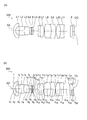
- FIG. 3A is a lens cross-sectional view of the stereoscopic endoscope 300 according to the first embodiment during normal observation.
- FIG. 3B is a lens cross-sectional view during near-point observation (enlarged observation) of the stereoscopic endoscope 300 according to the first embodiment. In this embodiment, -10% distortion is generated.
- the stereoscopic endoscope 300 includes, in order from the object side, a negative meniscus lens L1, a biconcave negative lens L2, a biconvex positive lens L3, and a parallel plate (infrared absorption filter).
- L4 aperture stop S
- positive meniscus lens L5 having a convex surface facing the image side
- biconcave negative lens L6 biconvex positive lens L7
- biconvex positive lens L8 and convex surface facing the image side
- It has a negative meniscus lens L9, a biconvex positive lens L10, a biconcave negative lens L11, a cover glass F, and a CCD cover glass CG.
- the biconcave negative lens L2 and the biconvex positive lens L3 are cemented.
- the biconcave negative lens L6 and the biconvex positive lens L7 are cemented.
- the biconvex positive lens L8 and the negative meniscus lens L9 having a convex surface facing the image side are cemented.
- the biconvex positive lens L10 and the biconcave negative lens L11 are cemented.
- cover glass F and the CCD cover glass CG are joined.
- d21 is an adhesive layer.
- a YAG laser cut coating is applied to the object side of the infrared absorption filter L4, and an LD laser cut coating is applied to the image side.
- the parallel plate L4, the aperture stop S, and the positive meniscus lens L5 are integrally moved to the image side to perform normal observation and near point (enlarged) observation.
- FIG. 4A is a lens cross-sectional view of the stereoscopic endoscope 400 according to the second embodiment during normal observation.
- FIG. 4B is a lens cross-sectional view of the stereoscopic endoscope 400 according to the second embodiment during near-point observation. In this embodiment, a distortion of -16% is generated.
- the stereoscopic endoscope 400 includes a negative meniscus lens L1, a biconcave negative lens L2, a biconvex positive lens L3, a parallel flat plate (infrared absorbing filter) with a convex surface facing the object side in order from the object side.
- the biconcave negative lens L2 and the biconvex positive lens L3 are cemented.
- the planoconcave negative lens L6 and the biconvex positive lens L7 are cemented.
- the biconvex positive lens L8 and the negative meniscus lens L9 having a convex surface facing the image side are cemented.
- the biconvex positive lens L10 and the biconcave negative lens L11 are cemented.
- cover glass F and the CCD cover glass CG are joined.
- d21 is an adhesive layer.
- a YAG laser cut coating is applied to the object side of the infrared absorption filter L4, and an LD laser cut coating is applied to the image side.
- the parallel plate L4, the aperture stop S, and the planoconvex positive lens L5 are integrally moved to the image side to perform normal observation and near point (enlarged) observation.
- r are the radii of curvature of the lens surfaces
- d is the distance between the lens surfaces
- ne is the refractive index of the e-line of each lens
- ⁇ e is the Abbe number of each lens
- * is an aspherical surface.
- the stop is an aperture stop.
- the aspherical shape is expressed by the following equation when the optical axis direction is z, the direction orthogonal to the optical axis is y, the conical coefficient is k, and the aspherical coefficients are A4, A6, A8, and A10. .
- z (y 2 / r) / [1+ ⁇ 1 ⁇ (1 + k) (y / r) 2 ⁇ 1/2 ] + A4y 4 + A6y 6 + A8y 8 + A10y 10
- E ⁇ n (n is an integer) indicates “10 ⁇ n ”.
- the symbols of these specification values are common in the numerical data of the embodiments.
- the above-described stereoscopic endoscope may satisfy a plurality of configurations at the same time. This is preferable in obtaining a good stereoscopic endoscope. Moreover, the combination of a preferable structure is arbitrary. Further, for each condition, only the upper limit value or lower limit value of the numerical range of the more limited condition may be limited.
- the present invention has a high resolution in the depth direction, appropriately reproduces the shape of the subject, and provides a suitable stereoscopic view in which neither the subject in the central part nor the subject in the peripheral part protrudes inappropriately. It is useful for a stereoscopic endoscope that can be used.
Landscapes
- Physics & Mathematics (AREA)
- Health & Medical Sciences (AREA)
- Life Sciences & Earth Sciences (AREA)
- Optics & Photonics (AREA)
- Surgery (AREA)
- Engineering & Computer Science (AREA)
- General Physics & Mathematics (AREA)
- General Health & Medical Sciences (AREA)
- Radiology & Medical Imaging (AREA)
- Medical Informatics (AREA)
- Public Health (AREA)
- Heart & Thoracic Surgery (AREA)
- Pathology (AREA)
- Molecular Biology (AREA)
- Animal Behavior & Ethology (AREA)
- Nuclear Medicine, Radiotherapy & Molecular Imaging (AREA)
- Biomedical Technology (AREA)
- Veterinary Medicine (AREA)
- Signal Processing (AREA)
- Biophysics (AREA)
- Multimedia (AREA)
- Astronomy & Astrophysics (AREA)
- Endoscopes (AREA)
- Instruments For Viewing The Inside Of Hollow Bodies (AREA)
- Lenses (AREA)
Abstract
第1の対物光学系OBL1と、第2の対物光学系OBL2と、第1の対物光学系OBL1の視野範囲に対応する撮像範囲を有する第1の撮像素子IMG1と、第2の対物光学系OBL2の視野範囲に対応する撮像範囲を有する第2の撮像素子IMG2と、モニター101と、からなり、以下の条件(1)及び条件(2)を満たすことを特徴とする。 条件(1)は、第1距離DT1と第2距離DT2との和に、モニター101の倍率を乗算した第1の値と、モニターの表示画面の縦の大きさT(mm)との割合が、1.5%より大きく、10.5%より小さいこと、 条件(2)は、第3距離と第4距離との差分に、モニター101の倍率を乗算した第2の値と、モニターの表示画面の縦の大きさTとの割合が、1.2%より大きく、7.5%より小さいこと、 である。
Description
本発明は、立体内視鏡に関するものである。
近年、医療分野では、病変の精密かつ迅速な手術を行うために、立体観察が可能な手術用内視鏡が重要視されている。特に外科手術の分野では、観察距離10mm~100mm程度の範囲で、安全かつ快適に立体画像の観察をできることが必要である。
精密な作業を正確に行うためには、奥行き方向の分解能を向上することが望ましい。また、作業を容易化するためには、被写体の実物の形状を忠実に3Dモニターで再現することが望ましい。
2つの対物光学系が内蔵された立体内視鏡において、奥行きの分解能を上げるためには、2つの対物光学系の光軸間の距離を離すことが必要である。一方、被写体の形状を忠実に再現するためには、各対物光学系のディストーションを抑えることが必要である。
ここで、2つの対物光学系の配置に関して光軸間距離を離すと、奥行き分解能は向上する。しかしながら、画面中心の近点に存在する物体が飛び出して見えてしまう。このため、快適な立体画像にならない。
さらに、ディストーションを抑えた2つの対物光学系の光軸間距離を離して配置した場合、画面中心部だけでなく、画面周辺部の近点に存在する物体も飛び出して見えてしまう。このため、快適な立体画像を得ることができない。
例えば、特許文献1に開示された立体的可視化システムは、GI(消化管)用途である。このため、手術用内視鏡とは、被写体との観察距離が異なる。特許文献1の構成では、近点観察のみ考慮されている。そして、2つの光学系の光軸間隔は、1mm程度しかない。さらに、クロスポイント(詳細は後述する)も10mm以下であり、短い距離である。特許文献1の構成を、例えば外科手術に使用した場合、立体感が弱いために、立体視の利点が発揮されない。すなわち、特許文献1に開示された立体的可視化システムでは、前後方向(奥行き方向)を認知することが困難であり、安全に精確な作業ができない。
同様に、特許文献2、3、4に開示された構成は、奥行き方向に高分解能を有することが困難である。また、特許文献2、3、4に開示された構成は、被写体の形状を適切に再現することが困難な場合、及び視野の中心部、周辺部に存在する被写体が飛び出して見えてしまう場合がある。
本発明は、上記を鑑みてなされたものであって、奥行き方向に高分解能を有し、被写体の形状を適切に再現しつつ、中心部の被写体、周辺部の被写体も共に不適切に飛び出さない好適な立体視ができる立体内視鏡を提供することを目的とする。
上述した課題を解決し、目的を達成するために、本発明の少なくとも幾つかの実施形態に係る立体内視鏡は、第1の対物光学系と、第2の対物光学系と、第1の対物光学系の視野範囲に対応する撮像範囲を有する第1の撮像素子と、第2の対物光学系の視野範囲に対応する撮像範囲を有する第2の撮像素子と、モニターと、からなり、以下の条件(1)及び条件(2)を満たすことを特徴とする。
条件(1)は、第1距離と第2距離との和に、モニターの倍率を乗算した第1の値と、前記モニターの表示画面の縦の大きさT(mm)との割合が、1.5%より大きく、10.5%より小さいこと、
条件(2)は、第3距離と第4距離との差分に、モニターの倍率を乗算したモニターの表示画面の縦の大きさTとの割合が、1.2%より大きく、7.5%より小さいこと、
ここで、
第1距離は、第1の撮像素子の撮像面のうちの撮像範囲の中心と、観察距離が30mmにおける第1の対物光学系及び第2の対物光学系の光軸間隔の中間位置に存在する第1物体が第1の撮像素子に結像した位置と、の距離、
第2距離は、第2の撮像素子の撮像面のうちの撮像範囲の中心と、第1物体が第2の撮像素子に結像した位置と、の距離、
第3距離は、第1の撮像素子の撮像面のうちの撮像範囲の中心と、観察距離が30mmにおける第1の撮像素子または第2の撮像素子のいずれか一方の撮像素子の視野範囲の視差方向の最端点に存在する第2物体が第1の撮像素子に結像した位置と、の距離、
第4距離は、第2の撮像素子の撮像面のうちの撮像範囲の中心と、第2物体が第2の撮像素子に結像した位置と、の距離、
である。
条件(1)は、第1距離と第2距離との和に、モニターの倍率を乗算した第1の値と、前記モニターの表示画面の縦の大きさT(mm)との割合が、1.5%より大きく、10.5%より小さいこと、
条件(2)は、第3距離と第4距離との差分に、モニターの倍率を乗算したモニターの表示画面の縦の大きさTとの割合が、1.2%より大きく、7.5%より小さいこと、
ここで、
第1距離は、第1の撮像素子の撮像面のうちの撮像範囲の中心と、観察距離が30mmにおける第1の対物光学系及び第2の対物光学系の光軸間隔の中間位置に存在する第1物体が第1の撮像素子に結像した位置と、の距離、
第2距離は、第2の撮像素子の撮像面のうちの撮像範囲の中心と、第1物体が第2の撮像素子に結像した位置と、の距離、
第3距離は、第1の撮像素子の撮像面のうちの撮像範囲の中心と、観察距離が30mmにおける第1の撮像素子または第2の撮像素子のいずれか一方の撮像素子の視野範囲の視差方向の最端点に存在する第2物体が第1の撮像素子に結像した位置と、の距離、
第4距離は、第2の撮像素子の撮像面のうちの撮像範囲の中心と、第2物体が第2の撮像素子に結像した位置と、の距離、
である。
本発明は、奥行き方向に高分解能を有し、被写体の形状を適切に再現しつつ、中心部の被写体、周辺部の被写体も共に不適切に飛び出さない好適な立体視ができる立体内視鏡を提供できるという効果を奏する。
以下に、実施形態に係る立体内視鏡100を図面に基づいて詳細に説明する。なお、この実施形態により、この発明が限定されるものではない。
本実施形態は、第1の対物光学系と、第2の対物光学系と、第1の対物光学系の視野範囲に対応する撮像範囲を有する第1の撮像素子と、第2の対物光学系の視野範囲に対応する撮像範囲を有する第2の撮像素子と、モニターと、からなり、以下の条件(1)及び条件(2)を満たすことを特徴とする。
条件(1)は、第1距離と第2距離との和に、モニターの倍率を乗算した第1の値と、前記モニターの表示画面の縦の大きさT(mm)との割合が、1.5%より大きく、10.5%より小さいこと、
条件(2)は、第3距離と第4距離との差分に、モニターの倍率を乗算した第2の値と、前記モニターの表示画面の縦の大きさTとの割合が、1.2%より大きく、7.5%より小さいこと、である。
ここで、
第1距離は、第1の撮像素子の撮像面のうちの撮像範囲の中心と、観察距離が30mmにおける第1の対物光学系及び第2の対物光学系の光軸間隔の中間位置に存在する第1物体が第1の撮像素子に結像した位置と、の距離、
第2距離は、第2の撮像素子の撮像面のうちの撮像範囲の中心と、第1物体が第2の撮像素子に結像した位置と、の距離、
第3距離は、第1の撮像素子の撮像面のうちの撮像範囲の中心と、観察距離が30mmにおける第1の撮像素子または第2の撮像素子のいずれか一方の撮像素子の視野範囲の視差方向の最端点に存在する第2物体が第1の撮像素子に結像した位置と、の距離、
第4距離は、第2の撮像素子の撮像面のうちの撮像範囲の中心と、第2物体が第2の撮像素子に結像した位置と、の距離、
である。
条件(1)は、第1距離と第2距離との和に、モニターの倍率を乗算した第1の値と、前記モニターの表示画面の縦の大きさT(mm)との割合が、1.5%より大きく、10.5%より小さいこと、
条件(2)は、第3距離と第4距離との差分に、モニターの倍率を乗算した第2の値と、前記モニターの表示画面の縦の大きさTとの割合が、1.2%より大きく、7.5%より小さいこと、である。
ここで、
第1距離は、第1の撮像素子の撮像面のうちの撮像範囲の中心と、観察距離が30mmにおける第1の対物光学系及び第2の対物光学系の光軸間隔の中間位置に存在する第1物体が第1の撮像素子に結像した位置と、の距離、
第2距離は、第2の撮像素子の撮像面のうちの撮像範囲の中心と、第1物体が第2の撮像素子に結像した位置と、の距離、
第3距離は、第1の撮像素子の撮像面のうちの撮像範囲の中心と、観察距離が30mmにおける第1の撮像素子または第2の撮像素子のいずれか一方の撮像素子の視野範囲の視差方向の最端点に存在する第2物体が第1の撮像素子に結像した位置と、の距離、
第4距離は、第2の撮像素子の撮像面のうちの撮像範囲の中心と、第2物体が第2の撮像素子に結像した位置と、の距離、
である。
図1(a)、図1(b)、図2(a)、図2(b)を用いて、本実施形態を説明する。図1(a)は、立体内視鏡100が第1物体OBJ1を撮像するときの概略構成図である。図1(b)は、立体内視鏡100が第2物体OBJ2を撮像する時の別の概略構成図である。図2(a)は、立体内視鏡100のさらに別の図である。図2(b)は、立体内視鏡100で撮像した画像を再生する時の構成を示す図である。
まず、図1(a)、図1(b)、図2(a)、図2(b)を用いて説明する。立体内視鏡100は、第1の対物光学系OBL1、例えば左眼用対物光学系と、第2の対物光学系OBL2、例えば右眼用対物光学系と、を有する。第1の撮像素子IMG1は、第1の対物光学系OBL1に対応して撮像する位置に配置されている。第2の撮像素子IMG2は、第2の対物光学系OBL2に対応して撮像する位置に配置されている。また、撮像された像は、図2(b)に示すモニター101に表示される。
そして、立体内視鏡100は、以下の条件(1)及び条件(2)を満たしている。
条件(1)は、第1距離DT1と第2距離DT2との和に、モニター101の倍率を乗算した第1の値と、モニター表示画面のたての大きさTとの割合が1.5%より大きく、10.5%より小さいこと、
条件(2)は、第3距離DT3と第4距離DT4との差分に、モニター101の倍率を乗算した第2の値と、モニターの表示画面のたての大きさTとの割合が、1.2%より大きく、7.5%より小さいこと、である。
条件(1)は、第1距離DT1と第2距離DT2との和に、モニター101の倍率を乗算した第1の値と、モニター表示画面のたての大きさTとの割合が1.5%より大きく、10.5%より小さいこと、
条件(2)は、第3距離DT3と第4距離DT4との差分に、モニター101の倍率を乗算した第2の値と、モニターの表示画面のたての大きさTとの割合が、1.2%より大きく、7.5%より小さいこと、である。
第1距離DT1は、第1の撮像素子IMG1の撮像面のうちの撮像範囲の中心C1と、観察距離が30mmにおける第1の対物光学系OBL1及び第2の対物光学系OBL2の光軸AX1、AX2の間隔の中間位置に存在する第1物体OBJ1が第1の撮像素子IMG1に結像した位置I1Lと、の距離である。なお、図1(a)において、光軸AX1、AX2の中間を軸AXCで示している。
第2距離DT2は、第2の撮像素子IMG2の撮像面のうちの撮像範囲の中心C2と、第1物体OBJ1が第2の撮像素子IMG2に結像した位置I1Rと、の距離である。
第3距離DT3は、第1の撮像素子IMG1の撮像面のうちの撮像範囲の中心C1と、観察距離が30mmにおける第1の撮像素子IMG1または第2の撮像素子IMG2のいずれか一方の撮像素子の視野範囲の視差方向の最端点に存在する第2物体OBJ2が第1の撮像素子IMG1に結像した位置I2Lと、の距離である。
第4距離DT4は、第2の撮像素子IMG2の撮像面のうちの撮像範囲の中心C2と、第2物体OBJ2が第2の撮像素子IMG2に結像した位置I2Rと、の距離である。
第1物体OBJ1と第2物体OBJ2とは、それぞれ観察視野内の中心領域と周辺領域とに存在している。ここで周辺領域とは、視差が発生している方向の最周辺領域をいう。
ディスト―ションと光軸間隔の組み合わせにより、像の飛び出しと、像の盛り上がりの特性が決まる。上記条件(1)、(2)を満足することで、飛び出しと盛り上がりの適切なバランスを得ることができる。これにより、自然な立体感を得ることができる。
本実施形態において、第1の値Hcは、以下の式(A)で示される。
Hc=(2×M×β×(K/2)×(Dc+1)-2S×M×β)/T (A)
ここで、
Mは、モニター101の倍率(=(x’/x)×(Im/Ip))、
x’は、モニター101の画素数、
xは、第1の対物光学系OBL1及び第2の対物光学系OBL2の画素数、
Imは、モニター101の画素ピッチ、
Ipは、第1の撮像素子IMG1または第2の撮像素子IMG2の画素ピッチ、
βは、第1の対物光学系OBL1及び第2の対物光学系OBL2の倍率、
Kは、2つの対物光学系OBL1、OBL2の光軸AX1、AX2の間隔、
また、Kは、第1の対物光学系OBL1の瞳と第2の対物光学系OBLの瞳との間隔、または第1の対物光学系OBL1の開口部と第2の対物光学系OBL2の開口部との間隔でも良い。Tは、モニターの縦の大きさである。
また、画素数は、視差方向の画素数及び撮像素子の対角方向の画素数の何れでも良い。
Dcは、第1物体OBJ1が第1の撮像素子IMG1及び第2の撮像素子IMG2に結像した際のディストーション量(%)、即ち、視野範囲の中心に存在する第1物体OBJ1が結像する位置におけるディストーション量(%)、
Sは、第1の撮像素子IMG1の撮像面のうちの撮像範囲の中心C1と第1の対物光学系IMG1の光軸AX1との距離、または、第2の撮像素子IMG2の撮像面のうちの撮像範囲の中心C2と第2の対物光学系IMG2の光軸AX2との距離、
である。
Hc=(2×M×β×(K/2)×(Dc+1)-2S×M×β)/T (A)
ここで、
Mは、モニター101の倍率(=(x’/x)×(Im/Ip))、
x’は、モニター101の画素数、
xは、第1の対物光学系OBL1及び第2の対物光学系OBL2の画素数、
Imは、モニター101の画素ピッチ、
Ipは、第1の撮像素子IMG1または第2の撮像素子IMG2の画素ピッチ、
βは、第1の対物光学系OBL1及び第2の対物光学系OBL2の倍率、
Kは、2つの対物光学系OBL1、OBL2の光軸AX1、AX2の間隔、
また、Kは、第1の対物光学系OBL1の瞳と第2の対物光学系OBLの瞳との間隔、または第1の対物光学系OBL1の開口部と第2の対物光学系OBL2の開口部との間隔でも良い。Tは、モニターの縦の大きさである。
また、画素数は、視差方向の画素数及び撮像素子の対角方向の画素数の何れでも良い。
Dcは、第1物体OBJ1が第1の撮像素子IMG1及び第2の撮像素子IMG2に結像した際のディストーション量(%)、即ち、視野範囲の中心に存在する第1物体OBJ1が結像する位置におけるディストーション量(%)、
Sは、第1の撮像素子IMG1の撮像面のうちの撮像範囲の中心C1と第1の対物光学系IMG1の光軸AX1との距離、または、第2の撮像素子IMG2の撮像面のうちの撮像範囲の中心C2と第2の対物光学系IMG2の光軸AX2との距離、
である。
式(A)は、視野中心における物体の飛び出しを、光軸間隔Kにより制御することを規定している式である。
第1の値Hcが式(A)の下限値を下回ると、奥行き分解能が低くなってしまう。第1の値Hcが式(A)の上限値を上回ると、視野の中心領域に存在する物体の飛び出しが強すぎてしまい、快適に立体視できない。
本実施形態において、第2の値Hsは、以下の式(B)で示される。
Hs=(M×β×((ΔP+K)×(D+1)-ΔP×(D’+1)-2S))/T(B)
ここで、
Mは、モニター101の倍率(=(x’/x)×(Im/Ip))、
x’は、モニター101の画素数、
xは、第1の対物光学系OBL1及び第2の対物光学系OBL2の画素数、
Imは、モニター101の画素ピッチ、
Ipは、第1の撮像素子IMG1または第2の撮像素子IMG2の画素ピッチ、
βは、第1の対物光学系OBL1及び第2の対物光学系OBL2の倍率
ΔPは、第1の対物光学系OBL1または第2の対物光学系OBL2の光軸AX1、A
X2と垂直な方向の視野範囲の最大長と光軸間隔との差分、
Kは、2つの対物光学系OBL1、OBL2の光軸AX1、AX2の間隔、
Dは、第2物体OBJ2が第1の撮像素子IMG1に結像した際のディストーション量(%)、
D’は、第2物体OBJ2が第2の撮像素子IMG2に結像した際のディストーション量(%)、
Sは、第1の撮像素子IMG1の撮像面のうちの撮像範囲の中心C1と第1の対物光学系OBL1の光軸AX1との距離、または、第2の撮像素子IMG2の撮像面のうちの撮像範囲の中心C2と第2の対物光学系OBL2の光軸AX2との距離、
である。
Hs=(M×β×((ΔP+K)×(D+1)-ΔP×(D’+1)-2S))/T(B)
ここで、
Mは、モニター101の倍率(=(x’/x)×(Im/Ip))、
x’は、モニター101の画素数、
xは、第1の対物光学系OBL1及び第2の対物光学系OBL2の画素数、
Imは、モニター101の画素ピッチ、
Ipは、第1の撮像素子IMG1または第2の撮像素子IMG2の画素ピッチ、
βは、第1の対物光学系OBL1及び第2の対物光学系OBL2の倍率
ΔPは、第1の対物光学系OBL1または第2の対物光学系OBL2の光軸AX1、A
X2と垂直な方向の視野範囲の最大長と光軸間隔との差分、
Kは、2つの対物光学系OBL1、OBL2の光軸AX1、AX2の間隔、
Dは、第2物体OBJ2が第1の撮像素子IMG1に結像した際のディストーション量(%)、
D’は、第2物体OBJ2が第2の撮像素子IMG2に結像した際のディストーション量(%)、
Sは、第1の撮像素子IMG1の撮像面のうちの撮像範囲の中心C1と第1の対物光学系OBL1の光軸AX1との距離、または、第2の撮像素子IMG2の撮像面のうちの撮像範囲の中心C2と第2の対物光学系OBL2の光軸AX2との距離、
である。
式(B)は、視野周辺領域の物体の飛び出しを、光軸間隔とディストーションにより制御し、近点観察時に視野周辺に存在する鉗子の飛び出しは、ディストーションで制御することを規定している式である。また、視野中心における物体の飛び出しは、光軸間隔Kにより制御することを規定している式である。
第2の値Hsが式(B)の下限値を下回ると、近点観察時の周辺領域に存在する鉗子の飛び出しがきつくなってしまう。また、第2の値Hsが式(B)の上限値を上回ると、平面の被写体を観察したとき、実際の形状と異なる形状が再生されてしまう。
また、本実施形態の好ましい態様によれば、光軸AX1、AX2の間隔を適宜変化させて、条件(1)を決定することが望ましい。
また、本実施形態の好ましい態様によれば、第2物体OBJ2が第1の撮像素子IMG1及び第2の撮像素子IMG2に結像した際のディストーション量を適宜変化させて、条件(2)を決定することが望ましい。
また、本実施形態の好ましい態様によれば、条件(1)において、光軸間隔Kは2mm以上、6mm以下であることが望ましい。これにより、さらに奥行き分解能を向上し、中心領域の物体の飛び出しを抑えることができる。
また、本実施形態の好ましい態様によれば、条件(2)において、ディストーション量Dは-30%以上から-10%以下であることが望ましい。これにより、意図的にディストーションを発生させ、さらに視野周辺領域の物体の飛び出し、及び近点観察時に視野周辺に存在する鉗子の飛び出しを、抑えることができる。
また、本実施形態の好ましい態様によれば、第3距離DT3と第4距離DT4との差分に、モニター101の倍率を乗算した第2の値Hsが1.8%以上、7.2%以下であり、ディストーション量Dは、-22%以上から-10%以下であることが望ましい。これにより、ディストーション量を減らすことで、ディストーションの像のゆがみによる左右像の縦ズレを減らすことができる。
また、本実施形態の好ましい態様によれば、モニター101に表示される画像の中心点がゼロ視差となる観察距離は40mm以下であることが望ましい。
図2(a)に示す軸AXC上のクロスポイントCPは距離40mm以下であることが望ましいことを意味する。また、「ゼロ視差」とは、再生画像の中心点102がモニター101面上に存在することをいう(図2(b)参照)。なお、観察者は、80cmから2mの範囲でモニター101を観察する。
クロスポイントCPが40mm以下の場合でも、通常観察(遠点観察)時に、開散しないように立体内視鏡の構成を設定する。
以下、実施例について説明する。
(実施例1)
図3(a)は、実施例1に係る立体内視鏡300の通常観察時のレンズ断面図である。図3(b)は、実施例1に係る立体内視鏡300の近点観察(拡大観察)時のレンズ断面図である。本実施例は、-10%のディスト―ションを発生させている。
図3(a)は、実施例1に係る立体内視鏡300の通常観察時のレンズ断面図である。図3(b)は、実施例1に係る立体内視鏡300の近点観察(拡大観察)時のレンズ断面図である。本実施例は、-10%のディスト―ションを発生させている。
実施例1の立体内視鏡300は、物体側から順に、物体側に凸面を向けた負メニスカスレンズL1と、両凹負レンズL2と、両凸正レンズL3と、平行平板(赤外吸収フィルタ)L4と、開口絞りSと、像側に凸面を向けた正メニスカスレンズL5と、両凹負レンズL6と、両凸正レンズL7と、両凸正レンズL8と、像側に凸面を向けた負メニスカスレンズL9と、両凸正レンズL10と、両凹負レンズL11と、カバーガラスFと、CCDカバーガラスCGと、を有している。
両凹負レンズL2と両凸正レンズL3とは接合されている。両凹負レンズL6と両凸正レンズL7とは接合されている。両凸正レンズL8と像側に凸面を向けた負メニスカスレンズL9とは接合されている。両凸正レンズL10と両凹負レンズL11とは接合されている。
カバーガラスFとCCDカバーガラスCGとは接合されている。d21は接着層である。また、赤外吸収フィルタL4の物体側に、YAGレーザーカットのコーティング、像側にLDレーザーカットのコーティングを施している。
平行平板L4と、開口絞りSと、正メニスカスレンズL5と、が一体となって像側へ移動することで、通常観察と近点(拡大)観察を行う。
(実施例2)
図4(a)は、実施例2に係る立体内視鏡400の通常観察時のレンズ断面図である。図4(b)は、実施例2に係る立体内視鏡400の近点観察時のレンズ断面図である。本実施例は、-16%のディスト―ションを発生させている。
図4(a)は、実施例2に係る立体内視鏡400の通常観察時のレンズ断面図である。図4(b)は、実施例2に係る立体内視鏡400の近点観察時のレンズ断面図である。本実施例は、-16%のディスト―ションを発生させている。
実施例2の立体内視鏡400は、物体側から順に、物体側に凸面を向けた負メニスカスレンズL1と、両凹負レンズL2と、両凸正レンズL3と、平行平板(赤外吸収フィルタ)L4と、開口絞りSと、物体側に平面を向けた平凸正レンズL5と、物体側に平面を向けた平凹負レンズL6と、両凸正レンズL7と、両凸正レンズL8と、像側に凸面を向けた負メニスカスレンズL9と、両凸正レンズL10と、両凹負レンズL11と、カバーガラスFと、CCDカバーガラスCGと、を有している。
両凹負レンズL2と両凸正レンズL3とは接合されている。平凹負レンズL6と両凸正レンズL7とは接合されている。両凸正レンズL8と像側に凸面を向けた負メニスカスレンズL9とは接合されている。両凸正レンズL10と両凹負レンズL11とは接合されている。
カバーガラスFとCCDカバーガラスCGとは接合されている。d21は接着層である。また、赤外吸収フィルタL4の物体側に、YAGレーザーカットのコーティング、像側にLDレーザーカットのコーティングを施している。
平行平板L4と、開口絞りSと、平凸正レンズL5と、が一体となって像側へ移動することで、通常観察と近点(拡大)観察を行う。
以下に、上記各実施例の数値データを示す。記号は、rは各レンズ面の曲率半径、dは各レンズ面間の間隔、neは各レンズのe線の屈折率、νeは各レンズのアッベ数、*印は非球面である。絞りは開口絞りである。
また、非球面形状は、光軸方向をz、光軸に直交する方向をyにとり、円錐係数をk、非球面係数をA4、A6、A8、A10としたとき、次の式で表される。
z=(y2/r)/[1+{1-(1+k)(y/r)2}1/2]
+A4y4+A6y6+A8y8+A10y10
また、非球面係数において、「E-n」(nは整数)は、「10-n」を示している。
なお、これら諸元値の記号は実施例の数値データにおいて共通である。
z=(y2/r)/[1+{1-(1+k)(y/r)2}1/2]
+A4y4+A6y6+A8y8+A10y10
また、非球面係数において、「E-n」(nは整数)は、「10-n」を示している。
なお、これら諸元値の記号は実施例の数値データにおいて共通である。
数値実施例1
単位 mm
面データ
面番号 r d ne νe
物面 ∞ 43.4151 1
1* 2.3823 0.3949 1.81078 40.92
2* 0.9151 0.6777 1
3 -5.5508 0.8934 1.88815 40.76
4 1.9264 0.9687 1.76167 27.51
5 -4.397 0.1565可変 1
6 ∞ 0.2235 1.523 65.13
7 ∞ 0.0284 1
8(絞り) ∞ 0 1
9 -9.5812 0.2981 1.65425 58.55
10 -7.5594 0.849可変 1
11 -26.843 0.3181 1.93429 18.9
12 5.4361 0.747 1.67765 32.1
13 -2.6970 0.0656 1
14 7.2754 1.2102 1.74795 44.78
15 -4.2565 0.8066 1.93429 18.9
16 -5.1872 0.0745 1
17 3.3362 0.7915 1.59143 61.14
18 -3.5799 0.5961 1.93429 18.9
19 19.0140 1.1782 1
20 ∞ 0.3726 1.51825 64.14
21 ∞ 0.0149 1.5119 64.05
22 ∞ 0.2981 1.507 63.26
像面 ∞ 0
非球面データ
第1面
k=0
A2=0.00E+00,A4=5.3715E-02,A6=-3.4719E-03,A8=8.1102E-04
第2面
k=0
A2=0.00E+00,A4=8.0179E-02,A6=2.3258E-02,A8=6.6214E-02
各種データ
通常観察 拡大観察
物体距離 43.41506 32.19677
d5 0.15648 0.33562
d10 0.849 0.66986
第1の値Hc=9.8%
第2の値Hs=7.15%
単位 mm
面データ
面番号 r d ne νe
物面 ∞ 43.4151 1
1* 2.3823 0.3949 1.81078 40.92
2* 0.9151 0.6777 1
3 -5.5508 0.8934 1.88815 40.76
4 1.9264 0.9687 1.76167 27.51
5 -4.397 0.1565可変 1
6 ∞ 0.2235 1.523 65.13
7 ∞ 0.0284 1
8(絞り) ∞ 0 1
9 -9.5812 0.2981 1.65425 58.55
10 -7.5594 0.849可変 1
11 -26.843 0.3181 1.93429 18.9
12 5.4361 0.747 1.67765 32.1
13 -2.6970 0.0656 1
14 7.2754 1.2102 1.74795 44.78
15 -4.2565 0.8066 1.93429 18.9
16 -5.1872 0.0745 1
17 3.3362 0.7915 1.59143 61.14
18 -3.5799 0.5961 1.93429 18.9
19 19.0140 1.1782 1
20 ∞ 0.3726 1.51825 64.14
21 ∞ 0.0149 1.5119 64.05
22 ∞ 0.2981 1.507 63.26
像面 ∞ 0
非球面データ
第1面
k=0
A2=0.00E+00,A4=5.3715E-02,A6=-3.4719E-03,A8=8.1102E-04
第2面
k=0
A2=0.00E+00,A4=8.0179E-02,A6=2.3258E-02,A8=6.6214E-02
各種データ
通常観察 拡大観察
物体距離 43.41506 32.19677
d5 0.15648 0.33562
d10 0.849 0.66986
第1の値Hc=9.8%
第2の値Hs=7.15%
数値実施例2
単位 mm
面データ
面番号 r d ne νe
物面 ∞ 60.0000 1
1* 2.9142 0.4 1.81078 40.88
2* 1.0606 0.84 1
3 -18.377 0.5 2.01169 28.27
4 2.634 1.2 1.85504 23.78
5 -8.532 0.21可変 1
6 ∞ 0.3 1.523 65.13
7 ∞ 0.03 1
8(絞り) ∞ 0.11 1
9 ∞ 0.35 1.65425 58.55
10 -35.645 0.72可変 1
11 ∞ 0.4 2.01169 28.27
12 9.972 0.78 1.80642 34.97
13 -3.375 0.08 1
14 24.688 0.9 1.73234 54.68
15 -2.782 0.53 1.93429 18.9
16 -5.625 1.2453 1
17 3.375 1.3 1.73234 54.68
18 -3.375 0.35 2.01169 28.27
19 8.042 0.856 1
20 ∞ 0.5 1.51825 64.14
21 ∞ 0.02 1.5119 64.05
22 ∞ 0.4 1.507 63.26
像面 ∞ 0
非球面データ
第1面
k=0.8038
A2=0.00E+00,A4=7.55E-04,A6=5.60E-04,A8=-1.86E-04
第2面
k=-0.1138
A2=0.00E+00,A4=2.51E-03,A6=-7.25E-04,A8=4.59E-03
各種データ
通常観察 拡大観察
物体距離 60 30
d5 0.21 0.68
d10 0.72 0.25
第1の値Hc=7.77%
第2の値Hs=4.71%
単位 mm
面データ
面番号 r d ne νe
物面 ∞ 60.0000 1
1* 2.9142 0.4 1.81078 40.88
2* 1.0606 0.84 1
3 -18.377 0.5 2.01169 28.27
4 2.634 1.2 1.85504 23.78
5 -8.532 0.21可変 1
6 ∞ 0.3 1.523 65.13
7 ∞ 0.03 1
8(絞り) ∞ 0.11 1
9 ∞ 0.35 1.65425 58.55
10 -35.645 0.72可変 1
11 ∞ 0.4 2.01169 28.27
12 9.972 0.78 1.80642 34.97
13 -3.375 0.08 1
14 24.688 0.9 1.73234 54.68
15 -2.782 0.53 1.93429 18.9
16 -5.625 1.2453 1
17 3.375 1.3 1.73234 54.68
18 -3.375 0.35 2.01169 28.27
19 8.042 0.856 1
20 ∞ 0.5 1.51825 64.14
21 ∞ 0.02 1.5119 64.05
22 ∞ 0.4 1.507 63.26
像面 ∞ 0
非球面データ
第1面
k=0.8038
A2=0.00E+00,A4=7.55E-04,A6=5.60E-04,A8=-1.86E-04
第2面
k=-0.1138
A2=0.00E+00,A4=2.51E-03,A6=-7.25E-04,A8=4.59E-03
各種データ
通常観察 拡大観察
物体距離 60 30
d5 0.21 0.68
d10 0.72 0.25
第1の値Hc=7.77%
第2の値Hs=4.71%
なお、上述の立体内視鏡は、複数の構成を同時に満足してもよい。このようにすることが、良好な立体内視鏡を得る上で好ましい。また、好ましい構成の組み合わせは任意である。また、各条件について、より限定した条件の数値範囲の上限値あるいは下限値のみを限定しても構わない。
以上、本発明の種々の実施形態について説明したが、本発明は、これらの実施形態のみに限られるものではなく、その趣旨を逸脱しない範囲で、これら実施形態の構成を適宜組合せて構成した実施形態も本発明の範疇となるものである。
以上のように、本発明は、奥行き方向に高分解能を有し、被写体の形状を適切に再現しつつ、中心部の被写体、周辺部の被写体も共に不適切に飛び出さない好適な立体視ができる立体内視鏡に有用である。
DT1 第1距離
DT2 第2距離
DT3 第3距離
DT4 第4距離
IMG1 第1の撮像素子
IMG2 第2の撮像素子
OBL1 第1の対物光学系
OBL2 第2の対物光学系
AX1、AX2 光軸
AXC 軸
CP クロスポイント
I1L 位置
I1R 位置
I2L 位置
I2R 位置
OBJ1 第1物体
OBJ2 第2物体
C1 撮像面のうちの撮像範囲の中心
C2 撮像面のうちの撮像範囲の中心
K 光軸間隔
Hc 第1の値
Hs 第2の値
100、300、400 立体内視鏡
101 モニター
102 再生画像の中心点
DT2 第2距離
DT3 第3距離
DT4 第4距離
IMG1 第1の撮像素子
IMG2 第2の撮像素子
OBL1 第1の対物光学系
OBL2 第2の対物光学系
AX1、AX2 光軸
AXC 軸
CP クロスポイント
I1L 位置
I1R 位置
I2L 位置
I2R 位置
OBJ1 第1物体
OBJ2 第2物体
C1 撮像面のうちの撮像範囲の中心
C2 撮像面のうちの撮像範囲の中心
K 光軸間隔
Hc 第1の値
Hs 第2の値
100、300、400 立体内視鏡
101 モニター
102 再生画像の中心点
Claims (7)
- 第1の対物光学系と、
第2の対物光学系と、
前記第1の対物光学系の視野範囲に対応する撮像範囲を有する第1の撮像素子と、
前記第2の対物光学系の視野範囲に対応する撮像範囲を有する第2の撮像素子と、
モニターと、からなり、
以下の条件(1)及び条件(2)を満たすことを特徴とする立体内視鏡。
条件(1)は、第1距離と第2距離との和に、前記モニターの倍率を乗算した第1の値と、前記モニターの表示画面の縦の大きさT(mm)との割合が、1.5%より大きく、10.5%より小さいこと、
条件(2)は、第3距離と第4距離との差分に、前記モニターの倍率を乗算した第2の値と、前記モニターの表示画面の縦の大きさTとの割合が、1.2%より大きく、7.5%より小さいこと、
である。
ここで、
前記第1距離は、前記第1の撮像素子の撮像面のうちの前記撮像範囲の中心と、観察距離が30mmにおける前記第1の対物光学系及び前記第2の対物光学系の光軸間隔の中間位置に存在する第1物体が前記第1の撮像素子に結像した位置と、の距離、
前記第2距離は、前記第2の撮像素子の撮像面のうちの前記撮像範囲の中心と、前記第1物体が前記第2の撮像素子に結像した位置と、の距離、
前記第3距離は、前記第1の撮像素子の撮像面のうちの前記撮像範囲の中心と、観察距離が30mmにおける前記第1の撮像素子または前記第2の撮像素子のいずれか一方の撮像素子の前記視野範囲の視差方向の最端点に存在する第2物体が前記第1の撮像素子に結像した位置と、の距離、
前記第4距離は、前記第2の撮像素子の撮像面のうちの前記撮像範囲の中心と、前記第2物体が前記第2の撮像素子に結像した位置と、の距離、
である。 - 前記第1の値は、以下の式(A)で示されることを特徴とする請求項1に記載の立体内視鏡。
(2×M×β×(K/2)×(Dc+1)-2S×M×β )/T (A)
ここで、
Mは、前記モニターの倍率、
βは、前記第1の対物光学系及び前記第2の対物光学系の倍率、
Kは、2つの前記対物光学系の光軸間隔、
Dcは、前記第1物体が前記第1の撮像素子及び前記第2の撮像素子に結像した際のディストーション量、
Sは、前記第1の撮像素子の撮像面のうちの前記撮像範囲の中心と前記第1の対物光学系の光軸との距離、または、前記第2の撮像素子の撮像面のうちの前記撮像範囲の中心と前記第2の対物光学系の光軸との距離、
である。 - 前記第2の値は、以下の式(B)で示されることを特徴とする請求項1に記載の立体内視鏡。
(M×β×((ΔP+K)×(D+1)-ΔP×(D’+1)-2S))/T (B)
ここで、
Mは、前記モニターの倍率、
βは、前記第1の対物光学系及び前記第2の対物光学系の倍率、
ΔPは、前記第1の対物光学系または前記第2の対物光学系の光軸と垂直な方向の視野範囲の最大長と光軸間隔との差分、
Kは、2つの前記対物光学系の光軸間隔、
Dは、前記第2物体が前記第1の撮像素子に結像した際のディストーション量、
D’は、前記第2物体が前記第2の撮像素子に結像した際のディストーション量、
Sは、前記第1の撮像素子の撮像面のうちの前記撮像範囲の中心と前記第1の対物光学系の光軸との距離、または、前記第2の撮像素子の撮像面のうちの前記撮像範囲の中心と前記第2の対物光学系の光軸との距離、
である。 - 条件(1)において、前記光軸間隔は2mm以上、6mm以下であることを特徴とする請求項1に記載の立体内視鏡。
- 条件(2)において、前記第2物体が前記第1の撮像素子に結像した際の前記ディストーション量は-30%以上から-10%以下であることを特徴とする請求項3に記載の立体内視鏡。
- 前記第2の値が1.8%以上、7.2%以下であり、
前記第2物体が前記第1の撮像素子に結像した際の前記ディストーション量は、-22%以上から-10%以下であることを特徴とする請求項3に記載の立体内視鏡。 - 前記モニターに表示される画像の中心点がゼロ視差となる観察距離は40mm以下であることを特徴とする請求項1に記載の立体内視鏡。
Priority Applications (3)
| Application Number | Priority Date | Filing Date | Title |
|---|---|---|---|
| JP2018535442A JP6446161B1 (ja) | 2017-06-06 | 2018-04-19 | 立体内視鏡 |
| CN201880033238.0A CN110678115B (zh) | 2017-06-06 | 2018-04-19 | 立体内窥镜系统 |
| US16/698,871 US10827912B2 (en) | 2017-06-06 | 2019-11-27 | Stereoscopic endoscope system |
Applications Claiming Priority (2)
| Application Number | Priority Date | Filing Date | Title |
|---|---|---|---|
| JP2017-111793 | 2017-06-06 | ||
| JP2017111793 | 2017-06-06 |
Related Child Applications (1)
| Application Number | Title | Priority Date | Filing Date |
|---|---|---|---|
| US16/698,871 Continuation US10827912B2 (en) | 2017-06-06 | 2019-11-27 | Stereoscopic endoscope system |
Publications (1)
| Publication Number | Publication Date |
|---|---|
| WO2018225397A1 true WO2018225397A1 (ja) | 2018-12-13 |
Family
ID=64566133
Family Applications (1)
| Application Number | Title | Priority Date | Filing Date |
|---|---|---|---|
| PCT/JP2018/016134 Ceased WO2018225397A1 (ja) | 2017-06-06 | 2018-04-19 | 立体内視鏡 |
Country Status (4)
| Country | Link |
|---|---|
| US (1) | US10827912B2 (ja) |
| JP (1) | JP6446161B1 (ja) |
| CN (1) | CN110678115B (ja) |
| WO (1) | WO2018225397A1 (ja) |
Families Citing this family (1)
| Publication number | Priority date | Publication date | Assignee | Title |
|---|---|---|---|---|
| WO2018189853A1 (ja) * | 2017-04-13 | 2018-10-18 | オリンパス株式会社 | 立体視内視鏡光学系及びそれを備えた内視鏡 |
Citations (2)
| Publication number | Priority date | Publication date | Assignee | Title |
|---|---|---|---|---|
| JP2016046780A (ja) * | 2014-08-26 | 2016-04-04 | オリンパス株式会社 | 画像記録装置 |
| WO2016157623A1 (ja) * | 2015-03-30 | 2016-10-06 | オリンパス株式会社 | 内視鏡装置 |
Family Cites Families (8)
| Publication number | Priority date | Publication date | Assignee | Title |
|---|---|---|---|---|
| JP3220538B2 (ja) * | 1992-12-24 | 2001-10-22 | オリンパス光学工業株式会社 | 立体視内視鏡及び立体視内視鏡装置 |
| JP3540351B2 (ja) | 1994-03-02 | 2004-07-07 | オリンパス株式会社 | 立体視硬性内視鏡 |
| JPH0829701A (ja) * | 1994-07-18 | 1996-02-02 | Olympus Optical Co Ltd | 立体視内視鏡システム |
| WO2011113062A1 (en) | 2010-03-12 | 2011-09-15 | Viking Systems, Inc. | Stereoscopic visualization system |
| WO2013108500A1 (ja) * | 2012-01-18 | 2013-07-25 | オリンパスメディカルシステムズ株式会社 | 立体視内視鏡用光学系 |
| JP5996319B2 (ja) | 2012-07-31 | 2016-09-21 | オリンパス株式会社 | ステレオ計測装置およびステレオ計測装置の作動方法 |
| JP6280749B2 (ja) * | 2013-01-23 | 2018-02-14 | オリンパス株式会社 | 光学系、立体撮像装置、及び内視鏡 |
| WO2015083459A1 (ja) * | 2013-12-05 | 2015-06-11 | オリンパス株式会社 | 立体内視鏡システム |
-
2018
- 2018-04-19 WO PCT/JP2018/016134 patent/WO2018225397A1/ja not_active Ceased
- 2018-04-19 JP JP2018535442A patent/JP6446161B1/ja active Active
- 2018-04-19 CN CN201880033238.0A patent/CN110678115B/zh active Active
-
2019
- 2019-11-27 US US16/698,871 patent/US10827912B2/en active Active
Patent Citations (2)
| Publication number | Priority date | Publication date | Assignee | Title |
|---|---|---|---|---|
| JP2016046780A (ja) * | 2014-08-26 | 2016-04-04 | オリンパス株式会社 | 画像記録装置 |
| WO2016157623A1 (ja) * | 2015-03-30 | 2016-10-06 | オリンパス株式会社 | 内視鏡装置 |
Also Published As
| Publication number | Publication date |
|---|---|
| CN110678115B (zh) | 2021-11-05 |
| US10827912B2 (en) | 2020-11-10 |
| JP6446161B1 (ja) | 2018-12-26 |
| US20200093356A1 (en) | 2020-03-26 |
| CN110678115A (zh) | 2020-01-10 |
| JPWO2018225397A1 (ja) | 2019-06-27 |
Similar Documents
| Publication | Publication Date | Title |
|---|---|---|
| JP4934233B2 (ja) | 対物光学系 | |
| JP6261566B2 (ja) | 立体撮像光学系、立体撮像装置及び内視鏡 | |
| US10552948B2 (en) | Endoscope apparatus | |
| EP2579082A1 (en) | Image formation optical system and image pickup device | |
| JP2016001209A (ja) | 接眼レンズおよび撮像装置 | |
| JP2014174390A (ja) | 結像光学系、立体撮像装置、及び内視鏡 | |
| CN109124544B (zh) | 用于刚性内窥镜的中继光学系统以及内窥镜 | |
| US10105034B2 (en) | Endoscope apparatus | |
| CN105793756B (zh) | 立体摄像光学系统、立体摄像装置以及内窥镜 | |
| WO2018185955A1 (ja) | 変倍光学系及び撮像装置 | |
| US10842360B2 (en) | Objective optical system | |
| JP6446161B1 (ja) | 立体内視鏡 | |
| WO2015019605A1 (ja) | 接眼レンズ系および画像観察装置 | |
| WO2019008618A1 (ja) | 立体視用光学系及びそれを備えた撮像装置 | |
| CN110623626A (zh) | 用于二维腹腔镜的二维-三维成像转换器 | |
| JP4660873B2 (ja) | 平行系実体顕微鏡対物レンズ | |
| JPWO2020174561A1 (ja) | 内視鏡用対物光学系及び内視鏡 | |
| JP7537856B2 (ja) | 対物光学系、撮像装置及び内視鏡 | |
| JP2014206687A (ja) | リレー光学系 | |
| CN110623625A (zh) | 用于二维腹腔镜的三维成像转换器 | |
| JP2001021817A (ja) | 接眼レンズ |
Legal Events
| Date | Code | Title | Description |
|---|---|---|---|
| ENP | Entry into the national phase |
Ref document number: 2018535442 Country of ref document: JP Kind code of ref document: A |
|
| 121 | Ep: the epo has been informed by wipo that ep was designated in this application |
Ref document number: 18812683 Country of ref document: EP Kind code of ref document: A1 |
|
| NENP | Non-entry into the national phase |
Ref country code: DE |
|
| 122 | Ep: pct application non-entry in european phase |
Ref document number: 18812683 Country of ref document: EP Kind code of ref document: A1 |