WO2018221515A1 - 位置測定用の端末装置,コンピュータプログラム,及びシステム - Google Patents
位置測定用の端末装置,コンピュータプログラム,及びシステム Download PDFInfo
- Publication number
- WO2018221515A1 WO2018221515A1 PCT/JP2018/020558 JP2018020558W WO2018221515A1 WO 2018221515 A1 WO2018221515 A1 WO 2018221515A1 JP 2018020558 W JP2018020558 W JP 2018020558W WO 2018221515 A1 WO2018221515 A1 WO 2018221515A1
- Authority
- WO
- WIPO (PCT)
- Prior art keywords
- terminal device
- wireless tag
- tag
- base station
- distance
- Prior art date
- Legal status (The legal status is an assumption and is not a legal conclusion. Google has not performed a legal analysis and makes no representation as to the accuracy of the status listed.)
- Ceased
Links
Images



Classifications
-
- H—ELECTRICITY
- H04—ELECTRIC COMMUNICATION TECHNIQUE
- H04W—WIRELESS COMMUNICATION NETWORKS
- H04W64/00—Locating users or terminals or network equipment for network management purposes, e.g. mobility management
- H04W64/006—Locating users or terminals or network equipment for network management purposes, e.g. mobility management with additional information processing, e.g. for direction or speed determination
-
- H—ELECTRICITY
- H04—ELECTRIC COMMUNICATION TECHNIQUE
- H04W—WIRELESS COMMUNICATION NETWORKS
- H04W4/00—Services specially adapted for wireless communication networks; Facilities therefor
- H04W4/02—Services making use of location information
-
- G—PHYSICS
- G01—MEASURING; TESTING
- G01S—RADIO DIRECTION-FINDING; RADIO NAVIGATION; DETERMINING DISTANCE OR VELOCITY BY USE OF RADIO WAVES; LOCATING OR PRESENCE-DETECTING BY USE OF THE REFLECTION OR RERADIATION OF RADIO WAVES; ANALOGOUS ARRANGEMENTS USING OTHER WAVES
- G01S5/00—Position-fixing by co-ordinating two or more direction or position line determinations; Position-fixing by co-ordinating two or more distance determinations
- G01S5/0009—Transmission of position information to remote stations
- G01S5/0045—Transmission from base station to mobile station
- G01S5/0063—Transmission from base station to mobile station of measured values, i.e. measurement on base station and position calculation on mobile
-
- G—PHYSICS
- G01—MEASURING; TESTING
- G01S—RADIO DIRECTION-FINDING; RADIO NAVIGATION; DETERMINING DISTANCE OR VELOCITY BY USE OF RADIO WAVES; LOCATING OR PRESENCE-DETECTING BY USE OF THE REFLECTION OR RERADIATION OF RADIO WAVES; ANALOGOUS ARRANGEMENTS USING OTHER WAVES
- G01S5/00—Position-fixing by co-ordinating two or more direction or position line determinations; Position-fixing by co-ordinating two or more distance determinations
- G01S5/02—Position-fixing by co-ordinating two or more direction or position line determinations; Position-fixing by co-ordinating two or more distance determinations using radio waves
- G01S5/0284—Relative positioning
-
- G—PHYSICS
- G01—MEASURING; TESTING
- G01S—RADIO DIRECTION-FINDING; RADIO NAVIGATION; DETERMINING DISTANCE OR VELOCITY BY USE OF RADIO WAVES; LOCATING OR PRESENCE-DETECTING BY USE OF THE REFLECTION OR RERADIATION OF RADIO WAVES; ANALOGOUS ARRANGEMENTS USING OTHER WAVES
- G01S5/00—Position-fixing by co-ordinating two or more direction or position line determinations; Position-fixing by co-ordinating two or more distance determinations
- G01S5/02—Position-fixing by co-ordinating two or more direction or position line determinations; Position-fixing by co-ordinating two or more distance determinations using radio waves
- G01S5/14—Determining absolute distances from a plurality of spaced points of known location
-
- H—ELECTRICITY
- H04—ELECTRIC COMMUNICATION TECHNIQUE
- H04M—TELEPHONIC COMMUNICATION
- H04M1/00—Substation equipment, e.g. for use by subscribers
-
- H—ELECTRICITY
- H04—ELECTRIC COMMUNICATION TECHNIQUE
- H04W—WIRELESS COMMUNICATION NETWORKS
- H04W4/00—Services specially adapted for wireless communication networks; Facilities therefor
- H04W4/02—Services making use of location information
- H04W4/029—Location-based management or tracking services
-
- H—ELECTRICITY
- H04—ELECTRIC COMMUNICATION TECHNIQUE
- H04W—WIRELESS COMMUNICATION NETWORKS
- H04W64/00—Locating users or terminals or network equipment for network management purposes, e.g. mobility management
-
- G—PHYSICS
- G01—MEASURING; TESTING
- G01S—RADIO DIRECTION-FINDING; RADIO NAVIGATION; DETERMINING DISTANCE OR VELOCITY BY USE OF RADIO WAVES; LOCATING OR PRESENCE-DETECTING BY USE OF THE REFLECTION OR RERADIATION OF RADIO WAVES; ANALOGOUS ARRANGEMENTS USING OTHER WAVES
- G01S2205/00—Position-fixing by co-ordinating two or more direction or position line determinations; Position-fixing by co-ordinating two or more distance determinations
- G01S2205/01—Position-fixing by co-ordinating two or more direction or position line determinations; Position-fixing by co-ordinating two or more distance determinations specially adapted for specific applications
-
- H—ELECTRICITY
- H04—ELECTRIC COMMUNICATION TECHNIQUE
- H04W—WIRELESS COMMUNICATION NETWORKS
- H04W4/00—Services specially adapted for wireless communication networks; Facilities therefor
- H04W4/02—Services making use of location information
- H04W4/023—Services making use of location information using mutual or relative location information between multiple location based services [LBS] targets or of distance thresholds
-
- H—ELECTRICITY
- H04—ELECTRIC COMMUNICATION TECHNIQUE
- H04W—WIRELESS COMMUNICATION NETWORKS
- H04W4/00—Services specially adapted for wireless communication networks; Facilities therefor
- H04W4/02—Services making use of location information
- H04W4/025—Services making use of location information using location based information parameters
- H04W4/027—Services making use of location information using location based information parameters using movement velocity, acceleration information
-
- H—ELECTRICITY
- H04—ELECTRIC COMMUNICATION TECHNIQUE
- H04W—WIRELESS COMMUNICATION NETWORKS
- H04W4/00—Services specially adapted for wireless communication networks; Facilities therefor
- H04W4/80—Services using short range communication, e.g. near-field communication [NFC], radio-frequency identification [RFID] or low energy communication
Definitions
- the present invention relates to a terminal device capable of obtaining a positional relationship with a wireless tag and a computer program thereof.
- the present invention also relates to a position measurement system including a terminal device, a wireless tag, and a base station.
- a radio signal such as a beacon transmitted from a plurality of base stations is received by a terminal device, and the distance between each base station and the terminal device is obtained by measuring the reception strength of the radio signal at the terminal device, and the triangulation method
- a position measurement technique for specifying the position of a terminal device by using a method is known. If such a position measurement technology is used, the position of the terminal device can be specified without using, for example, GPS (Global Positioning System). Therefore, even in indoor or shaded areas where it is difficult to receive GPS satellite signals, The position of the terminal device can be obtained. In addition, there is an advantage that it is not necessary to install a network communication device in the terminal device itself.
- Patent Document 1 discloses a position measurement system for a radio wave identification reader using a beacon.
- This system includes a plurality of beacon devices, a radio wave identification tag, and a radio wave identification reader.
- the beacon is transmitted from each beacon device, and information already stored using the radio wave identification is transferred from the radio wave identification tag to the radio wave identification reader. And send.
- the radio wave identification reader calculates the current position using each beacon and receives information from the radio wave identification tag using radio wave identification. As a result, it is said that the position of the moving radio wave identification reader can be measured and the accuracy of the position measurement can be improved.
- the terminal device radio wave identification reader
- the terminal device can determine the position of the self terminal by measuring the relative positional relationship with the base station (beacon device). It was not possible to obtain the positional relationship between the device and other devices.
- the terminal device can accurately measure not only the position of the terminal itself but also the position of the wireless tag, there are various situations. It is useful in.
- the terminal device cannot measure the position of the wireless tag.
- an object of the present invention is to provide a technique that enables a terminal device to efficiently measure the positional relationship between the self terminal and the wireless tag.
- the mobile terminal specifies the position of the self terminal based on radio signals transmitted from a plurality of base stations, By receiving information about the distance between tags from the base station and specifying the position of the wireless tag, it is possible to determine the positional relationship between the terminal and the wireless tag without using GPS or the like Obtained knowledge. Then, the present inventors have conceived that the problems of the prior art can be solved based on the above knowledge, and have completed the present invention. More specifically, the present invention has the following configuration.
- the first aspect of the present invention relates to a terminal device.
- the terminal device includes an inter-base station distance measuring unit, a self-terminal location specifying unit, and a tag location specifying unit.
- the inter-base station distance measuring unit measures a first distance between the base station and the own terminal based on radio signals transmitted from a plurality of base stations provided at each reference position.
- the self-terminal position specifying unit specifies the position of the self-terminal based on the first distance obtained as described above.
- the tag position specifying unit specifies the position of the wireless tag based on at least information on the second distance between the base station and the wireless tag transmitted by the base station that has received the wireless signal transmitted by the wireless tag. .
- the present invention has various usage forms.
- the present invention can be used for animal observation. More specifically, if a wireless tag is attached to an animal (object) to be observed, the position of the animal can be immediately confirmed on the terminal device. In addition, for example, even if a wireless tag is attached to the property and it is lost, if the terminal device is within the range that can receive a wireless signal from the wireless tag, the terminal device loses it. The position of the object can be confirmed. In addition, for example, if a pedestrian has a wireless tag, a terminal device is mounted on the vehicle, and base stations are placed around intersections and traffic lights, the position of the pedestrian can be confirmed at the vehicle terminal device. It can also be used to avoid collisions between pedestrians and vehicles. However, the present invention is not limited to these usage forms, and can be applied to various products and services.
- the terminal device preferably further includes an inter-tag distance measuring unit.
- the inter-tag distance measuring unit measures a third distance between the wireless tag and the self terminal based on a wireless signal transmitted from the wireless tag.
- the wireless signal transmitted from the wireless tag includes identification information unique to the object to which the wireless tag is attached.
- a terminal device further has an imaging
- the imaging target estimation unit estimates that imaging of an object to which the wireless tag is attached is successful when the terminal is within a predetermined distance range from the wireless tag during imaging by the imaging unit.
- This embodiment is particularly useful for observing moving objects (such as animals). That is, when the terminal device is photographed near the object, it can be estimated that the object is photographed. Normally, it is necessary to analyze a captured image and determine whether or not an object is included in the image. However, according to the above-described embodiment, the processing in such a terminal device can be omitted.
- the terminal device may further include a shooting direction specifying unit that specifies a shooting direction by the shooting unit.
- the shooting target estimation unit can also estimate that the shooting of the object to which the wireless tag is attached has been successful.
- the imaging target estimation unit when shooting, if the terminal is within a predetermined distance range from the wireless tag and the shooting direction by the shooting unit matches the existing direction of the wireless tag, It may be presumed that the attached object has been successfully photographed.
- the second aspect of the present invention relates to a computer program.
- the computer program according to the present invention causes a portable information terminal such as a smartphone to function as the terminal device according to the first aspect described above.
- the computer program can be installed in advance in the portable information terminal, or can be downloaded to the portable information terminal through the Internet.
- the third aspect of the present invention relates to a position measurement system.
- the system according to the present invention includes a terminal device, a wireless tag, and a plurality of base stations provided at each reference position.
- the base station measures the second distance between the wireless tag and the own base station based on the wireless signal transmitted by the wireless tag, and transmits information related to the second distance to the terminal device.
- the terminal device measures the first distance between the base station and the self terminal based on a radio signal transmitted from the base station, specifies the position of the self terminal based on the first distance, and at least relates to the second distance Based on the information, the position of the wireless tag is specified.
- the positional relationship between the self terminal and the wireless tag can be efficiently measured in the terminal device.
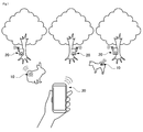
- FIG. 1 is a conceptual diagram showing an embodiment of a position measurement system.
- FIG. 2 is a block diagram showing a functional configuration of various devices constituting the position measurement system.
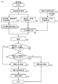
- FIG. 3 is a flowchart showing processing executed by the terminal device.
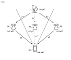
- FIG. 4 shows an example of a method for measuring the position of the terminal device and the wireless tag.
- FIG. 5 shows another example of a method for measuring the position of the terminal device and the wireless tag.
- FIG. 6 shows an example of a digital animal picture book.
- FIG. 1 shows an embodiment of a position measurement system 100 according to the present invention.
- 2 shows the functional configuration of various devices constituting the position measurement system.
- the position measurement system 100 includes a wireless tag 10 and a base station.
- a station 20, a terminal device 30, and a management server 40 are provided. Since the management server 40 is not an essential configuration, it can be omitted.
- the position measurement system 100 is used for animal management. More specifically, the wireless tag 10 is attached to an animal that is an object to be observed. A plurality of base stations 20 are installed in an area where animals are raised, and can be attached to, for example, a tree. Moreover, the terminal device 30 is possessed by the user of this system. Each base station 20 is provided at a reference position, and position information (position coordinates) of this reference position is known.
- the terminal device 30 receives a radio signal such as a beacon emitted from each base station 20 and measures the distance to each base station 20 by obtaining the reception strength thereof, and then determines its position by triangulation or the like. Identify information. Further, each base station 20 receives a radio signal such as a beacon emitted from the radio tag 10 and obtains the distance from the radio tag 10 by obtaining the reception intensity thereof. The distance between the base station 20 and the wireless tag 10 is transmitted from each base station 20 to the terminal device 30. Then, the terminal device 30 uses the information about the distance between the base station 20 and the wireless tag 10, or in addition to this, uses the information about the distance between the own terminal and the wireless tag 10 to use the wireless tag. 10 positions are specified.
- the display unit of the terminal device 30 may indicate the positional relationship between the self terminal and the wireless tag 10, specifically the distance to the wireless tag 10 and the direction in which the wireless tag 10 exists. It becomes possible.
- the configuration of each part of the position measurement system 100 will be described in detail.
- the wireless tag 10 is an electronic device attached to an object for specifying a position.
- the wireless tag 10 is realized by a wireless signal transmitter such as Bluetooth (registered trademark) or RFID (RadioRFIDFrequency IDentification), for example, by non-contact short-range wireless communication using an electromagnetic field or radio wave, Communication with the base station 20 and the terminal device 30 is performed.
- the circuit of the wireless tag 10 can employ, for example, a passive type, a semi-passive type, or a similar structure.
- the wireless tag 10 basically includes a transmitter 11 and an IC chip 12.
- the IC chip 12 has a storage unit that stores the wireless tag 10 or ID information (tag ID) unique to the object to which the wireless tag 10 is attached, and transmits a wireless signal including the tag ID via the transmission unit 11.
- the passive wireless tag 10 receives radio waves transmitted from the base station 20 and the terminal device 30 and converts the received radio waves into electromotive force by an antenna coil or a Schottky diode.
- the chip 12 is activated. When activated, the IC chip 12 reads the unique tag ID held in the storage unit, and transmits the unique tag ID read from the storage unit to the base station 20 and the terminal device 30 via the transmission unit 11. To do.
- the passive wireless tag 10 Since the passive wireless tag 10 operates by converting radio waves into electromotive force, it does not require a power source (for example, a battery), is inexpensive to manufacture, and can be used almost permanently. There is.
- a semi-passive wireless tag 10 can also be used.
- the semi-passive type wireless tag 10 receives a radio wave transmitted from the base station 20 or the terminal device 30 and activates an internal power source using this as a trigger. Then, using the power obtained from the power source, the IC chip 12 is activated, and a unique tag ID stored in the storage unit is transmitted to the base station 20 and the terminal device 30.
- the radio signal emitted from the radio tag 10 can reach a radius of about 1 m to 10 m, for example, and the reach range of the radio signal can be adjusted as appropriate.
- the short-range wireless communication among the wireless tag 10, the base station 20, and the terminal device 30 may be performed according to a known standard such as Bluetooth (registered trademark).
- the wireless tag 10 may include a biological sensor for sensing biological signals such as the heart rate sensor 12 and the body temperature sensor 13 and an operation sensor for sensing operation information of an object such as the acceleration sensor 14. Good.
- the heart rate sensor 12 measures the heart rate of the animal to which the wireless tag 10 is attached
- the body temperature sensor measures the body temperature of the animal.
- the acceleration sensor 13 measures the acceleration when the animal to which the wireless tag 10 is attached moves. Sensing information acquired by these various sensors 11 to 13 is transmitted to the base station 20 and the terminal device 30 through the transmitter 11 together with ID information (tag ID) unique to the wireless tag.
- each base station 20 includes a base station control unit 21, a storage unit 22, and a short-range wireless communication unit 23.
- the base station control unit 21 includes a processor such as a CPU, and controls the other elements 22 to 24.
- the storage unit 22 stores at least ID information (base station ID) unique to the base station.
- the storage unit 22 may store coordinate information where the base station 20 is installed.
- the base station control unit 22 reads the base station ID from the storage unit 22 and transmits the base station ID to the terminal device 30 through the short-range wireless communication unit 23.
- the base station control unit 22 can also transmit the position information (coordinate information) of the base station 20 to the terminal device 30 through the short-range wireless communication unit 23.
- the short-range wireless communication unit 23 receives a wireless signal from the wireless tag 10 and transmits predetermined information to the terminal device 30 according to a known standard such as Bluetooth (registered trademark).
- the base station control unit 21 includes an inter-tag distance measurement unit 21a.
- the inter-tag distance measuring unit 21 a receives a radio signal from the radio tag 10
- the inter-tag distance measuring unit 21 a measures the distance between the radio tag 10 and its own base station.
- the inter-tag distance measuring unit 21a may measure the reception strength of a wireless signal received from the wireless tag 10, for example, and obtain the distance from the wireless tag 10 based on the received strength.
- Information on the distance between the wireless tag 10 and the base station 20 is transmitted to the terminal device 30 through the short-range wireless communication unit 23 together with the tag ID of the wireless tag 10 and the base station ID of the base station 20. Accordingly, the terminal device 30 can identify which wireless tag 10 and the base station 20 have succeeded in communication, and acquire the distance between the wireless tag 10 and the base station 20 that are performing communication. be able to.
- the base station 20 may have a network communication unit 24.
- the base station 20 may transmit information about the date and time of communication with the wireless tag 10 and the distance obtained by the inter-tag distance measuring unit 21a to the management server 40 via the Internet via the network communication unit 24. it can. Further, the base station 20 can transmit the sensing information to the management server 40 when receiving the sensing information emitted from the wireless tag 10.
- the management server 40 registers various information received from the base station 20 in the database, thereby managing the action history and biological information of the animal to which the wireless tag 10 is attached. For example, if there is an abnormality in the behavior history or biological information of an animal, there is a possibility that an injury or illness has occurred. Therefore, such information is captured and managed by managing and analyzing the information with the management server 40.
- the terminal device 30 is a portable information terminal possessed by a user of this system. The user can know the positional relationship between the self terminal and the wireless tag 10 through the terminal device 30.
- the terminal device 30 includes a terminal control unit 31, a storage unit 32, a short-range wireless communication unit 33, a network communication unit 34, a shooting unit 35, a shooting direction specifying unit 36, a display unit 36, and an operation unit 37.
- a general function configuration of the terminal device 30 is illustrated. In this system, a plurality of terminal devices 30 may exist. All the terminal devices 30 do not have to have the same configuration, and may have different configurations.
- the terminal control unit 31 performs arithmetic processing for controlling other elements 32 to 38 included in the terminal device 30.
- a processor such as a CPU or a GPU can be used.
- the terminal control unit 31 reads an application program (computer program) stored in the storage unit 32 and controls other elements according to the application program. Further, the terminal control unit 31 can appropriately write or read the calculation result according to the application program in the storage unit 32.
- the storage unit 32 of the terminal device 30 is an element for storing information used for arithmetic processing or the like in the terminal control unit 11. More specifically, the storage unit 32 stores an application program that causes a general-purpose portable information communication terminal to function as the terminal device 30 according to the present invention.
- the application program may be downloaded to the terminal device 30 via the Internet, or may be preinstalled in the terminal device 30.
- the storage unit 32 may store other programs. When an application program is activated by an instruction from the user, processing according to this program is executed.
- the storage function of the storage unit 32 can be realized by a nonvolatile memory such as an HDD and an SDD.
- the storage unit 32 may have a function as a memory for writing or reading out the progress of the arithmetic processing by the terminal control unit 11.
- the memory function of the storage unit 32 can be realized by a volatile memory such as RAM or DRAM.
- the storage unit 32 of the terminal device 30 has a tag table that associates a tag ID unique to the wireless tag 10 and information about an object (for example, an animal) to which the wireless tag 10 is attached.
- the tag table stores ID information unique to the object to which the wireless tag 10 is attached and information such as the type, name, age, and icon image of the object, with the tag ID as a key item. For this reason, if the terminal device 30 can receive the tag ID from the wireless tag 10 or the base station 20, the wireless tag 10 is attached by reading various information associated with the tag ID from the tag table.
- the target object can be specified.
- the storage unit 32 of the terminal device 30 has a base station table that associates a base station ID unique to the base station 20 and position information of the base station 20.
- the base station table stores base station coordinate information using the base station ID as a key item.
- the coordinate information of the base station may be stored in advance in the base station table of the terminal device 30, or when the communication between the terminal device 30 and the base station 20 is successful, the base station 20 sends the terminal device 30. May have been sent to. If the terminal device 30 can receive the base station ID from the base station 20, the terminal device 30 identifies the position of the base station 20 by reading out the coordinate information of the base station associated with the base station ID from the base station table. Can do.
- information about the object can be stored in the base station table.
- the short-range wireless communication unit 32 of the terminal device 30 receives a wireless signal such as a beacon from the wireless tag 10 and the base station 20 according to a known standard such as Bluetooth (registered trademark).
- the wireless signal transmitted from the wireless tag 10 includes at least a tag ID unique to the wireless tag 10.
- the wireless signal of the wireless tag 10 may include sensing information acquired by the various sensors 12 to 15.
- the radio signal transmitted from the base station 20 includes a base station ID unique to the base station 20, a tag ID of the radio tag 10 that has communicated with the base station 20, and an inter-tag distance measuring unit 21a of the base station 20. Information on the measured distance between the base station 20 and the wireless tag 10 is included. Further, the radio signal of the base station 20 may include coordinate information of the base station 20.
- the short-range wireless communication unit 32 of the terminal device 30 can receive these pieces of information from the wireless tag 10 and the base station 20.
- the network communication unit 34 of the terminal device 30 communicates with the wireless tag 10 or the base station 20, the date and time of communication, the calculation result in the terminal control unit 31 (for example, information on the position of the own terminal and the position of the wireless tag, and successful shooting Information regarding the target object) can be transmitted to the management server 40 via the Internet.
- the terminal device 30 can transmit the sensing information to the management server 40.
- the management server 40 registers various information received from the terminal device 30 in the database, thereby managing the behavior history of the user having the terminal device 30, the behavior history of the animal to which the wireless tag 10 is attached, biometric information, and the like. .
- the photographing unit 35 is a camera for acquiring still image or moving image data.
- photography part 35 utilizes what was built in the terminal device 30.
- the image data acquired by the imaging unit 35 is sent to the terminal control unit 31 and subjected to predetermined calculation processing, and then stored in the storage unit 32.
- the camera is, for example, a lens, a mechanical shutter, a shutter driver, a photoelectric conversion element such as a CCD image sensor unit or a CMOS image sensor unit, a digital signal processor (DSP) that reads out the amount of charge from the photoelectric conversion element and generates image data, an IC memory, etc. It is realized with.
- the shooting direction specifying unit 36 has a function of specifying the direction (specifically, the shooting direction) of the terminal device 30 at the time of shooting.
- the function of the shooting direction specifying unit 36 can be realized by, for example, a known acceleration sensor 36a or gyro sensor 36b. Further, the acceleration sensor 36a detects a change in the moving speed of the terminal device 30. The gyro sensor 36 b detects a change in the tilt of the terminal device 30. Based on the information detected by the acceleration sensor 36a and the gyro sensor 36b, the terminal device 30 can specify the orientation at the time of shooting.
- the display unit 37 displays the calculation result by the terminal control unit 31 and the like.
- the display unit 37 is a display device such as an LCD (Liquid Crystal Display) or an OELD (Organic Electro Luminescence Display).
- the operation unit 38 has a function of accepting an operation input by the user and sending the input signal to the CPU 311. Examples of the operation unit 38 are a touch panel, a keyboard, a mouse, and a numeric keypad. Further, a touch panel display in which the display unit 37 and the operation unit 38 are integrated may be employed. As the touch panel display, a known method such as a capacitance method, an electromagnetic induction method, an infrared method, or a resistance film method can be adopted.
- the management server 40 is connected to the base station 20 and the terminal device 30 through the Internet, and manages information uploaded from these devices. Specifically, the management server 40 acquires information via the network communication unit 34, performs predetermined computations at the server control unit 41, and stores various types of information in the database 42.
- the database of the management server 40 may store sensing information (animal biological information) acquired by the wireless tag 10, position information / action history of the wireless tag 10, and position information / action history of the terminal device 30. it can.
- the management server 40 may provide an application program to the terminal device 30 and also provide a tag table and a base station table (which stores base station position information) to the terminal device 30. You can also
- the terminal control unit 31 of the terminal device 30 includes an inter-base station distance measuring unit 31a, a self-terminal location specifying unit 31b, a tag location specifying unit 31c, an inter-tag distance measuring unit 31d, and an imaging target estimating unit. 31e as a functional block.
- FIG. 3 is a flowchart showing processing executed by each functional block provided in the terminal device 30.
- the terminal device 30 receives wireless signals from the plurality of base stations 20 through the short-range wireless communication unit 33 (step S1). Since communication between the terminal device 30 and the base station 20 is performed by short-range wireless communication, the terminal device 30 receives radio signals from a plurality of base stations 20 located within a predetermined range (radius of about 1 to 10 m). It will be.
- the inter-base station distance measuring unit 31a of the terminal device 30 measures the distance between the own terminal and each base station 20 based on the radio signal received from the base station 20 (step S2).
- the distance between the self terminal and the base station can be measured based on, for example, the reception strength of the radio signal transmitted from the base station 20. That is, the stronger the radio signal reception strength, the closer the distance between the terminal and the base station.
- the inter-base station distance measuring unit 31a may calculate the distance to the base station based on the reception strength of the radio signal, or may refer to a table that associates the reception strength and the distance with the base station. You may ask for the distance between.
- the self terminal position specifying unit 31b of the terminal device 30 specifies the position of the self terminal based on the distance between the self terminal and the base station obtained as described above (step S3). Examples of the method for specifying the position of the terminal device 30 are shown in FIGS. As shown in FIG. 4 and FIG. 5, the xy coordinates (x1, y1), (x2, y2), (x3, y3) of the three base stations 20 are known. The distances a1, a2, and a3 are measured by the inter-base station distance measuring unit 31a of the terminal device 30.
- the self terminal location specifying unit 31b of the terminal device 30 obtains the coordinates (xa, ya) of the terminal device 30 by triangulation based on the xy coordinates of each base station 20 and the distance between the self terminal and the base station. be able to. Thus, if the terminal device 30 is in a position where radio signals can be received from at least three base stations 20, the coordinates of the terminal device 30 can be specified.
- the tag position specifying unit 31c of the terminal device 30 extracts information about the distance between the base station 20 and the wireless tag 10 included in the wireless signal of the base station 20 (step S4). That is, when the base station 20 receives a radio signal from the radio tag 10, the inter-tag distance measuring unit 21a measures the distance to the radio tag 10 and transmits the distance information on the radio signal. Yes. Therefore, the terminal device 30 can extract information on the distance between the base station and the tag from the radio signal transmitted from each base station 20 when the communication with the base station 20 is successful.
- the tag position specifying unit 31c specifies the position of the wireless tag 10 based on the base station-tag distance information obtained from the plurality of base stations 20 (step S5). For example, as shown in FIG. 5, the xy coordinates (x1, y1), (x2, y2), (x3, y3) of the three base stations 20 are known, and each base station 20 and the wireless tag 10 The distances b1, b2, and b3 are measured by the inter-tag distance measuring unit 31a of each base station 20 and transmitted from the base station 20 to the terminal device 30.
- the tag position specifying unit 31c of the terminal device 30 can obtain the coordinates (xb, yb) of the wireless tag 10 by the triangulation method based on the xy coordinates of each base station 20 and the base station-tag distance. it can.
- the terminal device 30 is in a position where radio signals can be received from at least three base stations 20, and if the three base stations 20 are in positions where radio signals can be received from the same radio tag 10, then the terminal Even when the device 30 and the wireless tag 10 are not in direct communication, the terminal device 30 can specify the coordinates of the wireless tag 10.
- the terminal device 30 may be able to communicate directly with the wireless tag 10 (step S6). Communication between the terminal device 30 and the wireless tag 10 is performed by short-range wireless communication, and the terminal device 30 receives a wireless signal from the wireless tag 10 located within a predetermined range (radius of about 1 to 10 m). .
- the inter-tag distance measuring unit 31d of the terminal device 30 measures the distance between the self terminal and the wireless tag 10 based on the wireless signal received from the wireless tag 10 (step S7). The distance between the self terminal and the tag can be measured based on, for example, the reception intensity of the radio signal transmitted by the radio tag 10. That is, the stronger the wireless signal reception strength, the closer the distance between the self terminal and the wireless tag 10.
- the inter-tag distance measuring unit 31d may calculate the distance to the wireless tag 10 based on the reception strength of the wireless signal, or may refer to the wireless tag 10 with reference to a table in which the reception strength and the distance are associated with each other. You may ask for the distance between.
- the tag position specifying unit 31c of the terminal device 30 can also specify the position of the wireless tag 10 using the distance between the self terminal and the tag (step S5).
- the xy coordinates (x1, y1) and (x2, y2) of the two base stations 20 are known, and the base station 20 and the wireless tag 10 are determined by these two base stations 20.
- the distances b1 and b2 are measured and transmitted to the terminal device 30.
- the xy coordinates (xa, xb) of the terminal device 30 have already been specified in step S3, and the distance b3 between the terminal device 30 and the wireless tag 10 has already been measured in step S7.
- the tag position specifying unit 31c of the terminal device 30 includes the xy coordinates (x1, y1) and (x2, y2) of the two base stations 20, the xy coordinates (xa, xb) of the own terminal, and the two base stations ⁇ Based on the inter-tag distances b1, b2, and the self-terminal-tag distance b3, the coordinates (xb, yb) of the wireless tag 10 can be obtained by the triangulation method.
- the terminal device 30 specifies the coordinates of the wireless tag 10. be able to.
- the terminal device 30 obtains the position information of the self terminal and the position information of the wireless tag 10.
- the position information of the self-terminal and the wireless tag 10 obtained in this way may be displayed on the display unit 37.
- the terminal device 30 and the wireless tag 10 are displayed on the map image, the user can easily grasp the positional relationship between the terminal device 30 and the wireless tag 10.
- information on the object (animal or the like) to which the wireless tag 10 is attached for example, the type or name of the object, an icon image, or the like can be displayed.
- the terminal device 30 may display the distance and direction to the wireless tag 10.
- step S8 the photographing unit 35 provided in the terminal device 30 has photographed.
- the shooting target estimation unit 31e of the terminal device 30 determines whether the distance between the self terminal and the wireless tag 10 is within a predetermined range (step S9).
- the distance between them can be obtained based on these coordinates.
- the distance between the terminal device 30 and the wireless tag 10 can be measured based on the reception strength of the wireless signal of the wireless tag 10.
- the predetermined range here can be adjusted as appropriate, but may be, for example, about 1 m to 5 m.
- the shooting target estimation unit 31 e of the terminal device 30 determines that the distance between the terminal itself and the wireless tag 10 is within a predetermined range, the shooting of the wireless tag 10 is successful. Is determined (step S11). On the other hand, if the imaging target estimation unit 31e determines that the distance between the own terminal and the wireless tag 10 is not within the predetermined range, whether or not the imaging direction of the imaging unit 35 and the existence direction of the wireless tag 10 match. Is determined (step S10). As described above, since the coordinates (xa, ya) of the terminal device 30 and the coordinates (xb, yb) of the wireless tag 10 have already been specified, the positional relationship between them can be obtained based on these coordinates.
- the shooting direction may be determined by considering the angle of view of the shooting unit 35 and determining whether or not the wireless tag 10 exists within the range of the angle of view.
- the shooting target estimation unit 31 e of the terminal device 30 has a shooting direction of the wireless tag 10 even when the distance between the self-terminal and the wireless tag 10 is not within a predetermined range. If it is determined that the present direction matches, the wireless tag 10 is determined to have been successfully photographed (step S11). On the other hand, if the distance between the self terminal and the wireless tag 10 is not within the predetermined range and the shooting direction does not match the wireless tag 10, it is determined that the shooting has failed (step S12).
- the OR condition for determining “successful imaging” is satisfied if either “distance between terminal device and wireless tag” or “imaging direction” is satisfied.
- the AND condition is preferable when the subject to be photographed is a small animal at a place touched by the user, and the OR condition may be adopted when the subject is an animal at a remote place such as birds.
- the recreation difficulty is generally easier for the OR condition and more difficult for the AND condition.
- the shooting target estimation unit 31e estimates the type of the target object using the ID information of the wireless tag 10 determined to have been shot successfully (step S13). That is, the tag table of the storage unit 32 of the terminal device 30 stores information related to the type of the object to which the tag is attached in association with the tag ID of the wireless tag 10. Therefore, if the tag table is searched using the tag ID as a key, the type of the object can be specified. By performing the processing from step S9 to step S13, the photographing target can be easily estimated. In other words, in order to accurately specify the shooting target, advanced image processing such as analysis of the shot image and extraction of an object included in the image is required. Even if image processing is not performed, it is possible to estimate the shooting target with a certain degree of accuracy.
- step S13 it is possible to perform image processing after step S13 to verify whether or not the photographing target estimated in step S13 is correct.
- the terminal control unit 31 of the terminal device 30 stores the captured image captured in step S8 in the storage unit 32 in association with the target type specified in step S13 (step S14).
- the storage unit 32 is provided with a storage space for storing the captured image, and the captured image is preferably stored in the storage unit 32 in a picture book format.
- FIG. 6 shows an example of a pictorial book for storing captured images.
- a captured image of an object (animal) can be recorded separately for each type of object. For example, no.
- a photographed image for rabbits can be recorded.
- a photographed image for dogs can be recorded.
- the photographed image is designated as No. 1. Save in the storage area for 002 (storage area for rabbits). In this way, if the photographed image can be stored in the picture book format, a recreation that the photographed image is collected while observing the animal can be provided to the user who possesses the terminal device 30.
- the present invention relates to a terminal device capable of obtaining a positional relationship with a wireless tag.
- the present invention can be used in various scenes such as observation of animals, discovery of lost items, avoidance of traffic accidents, and the present invention is not limited to these modes of use, and can be applied to various products and services. can do.
Landscapes
- Engineering & Computer Science (AREA)
- Signal Processing (AREA)
- Computer Networks & Wireless Communication (AREA)
- Physics & Mathematics (AREA)
- General Physics & Mathematics (AREA)
- Radar, Positioning & Navigation (AREA)
- Remote Sensing (AREA)
- Mobile Radio Communication Systems (AREA)
- Position Fixing By Use Of Radio Waves (AREA)
- Telephone Function (AREA)
Priority Applications (3)
| Application Number | Priority Date | Filing Date | Title |
|---|---|---|---|
| SG11201912542WA SG11201912542WA (en) | 2017-06-02 | 2018-05-29 | Terminal device for position measurement, computer program, and system |
| CN201880034988.XA CN110678771B (zh) | 2017-06-02 | 2018-05-29 | 位置测量用终端装置、存储有计算机程序的记录介质及系统 |
| US16/618,399 US10841895B2 (en) | 2017-06-02 | 2018-05-29 | Terminal device for position measurement, computer program, and system |
Applications Claiming Priority (2)
| Application Number | Priority Date | Filing Date | Title |
|---|---|---|---|
| JP2017-110494 | 2017-06-02 | ||
| JP2017110494A JP6573936B2 (ja) | 2017-06-02 | 2017-06-02 | 位置測定用の端末装置,コンピュータプログラム,及びシステム |
Publications (1)
| Publication Number | Publication Date |
|---|---|
| WO2018221515A1 true WO2018221515A1 (ja) | 2018-12-06 |
Family
ID=64456300
Family Applications (1)
| Application Number | Title | Priority Date | Filing Date |
|---|---|---|---|
| PCT/JP2018/020558 Ceased WO2018221515A1 (ja) | 2017-06-02 | 2018-05-29 | 位置測定用の端末装置,コンピュータプログラム,及びシステム |
Country Status (6)
| Country | Link |
|---|---|
| US (1) | US10841895B2 (enExample) |
| JP (1) | JP6573936B2 (enExample) |
| CN (1) | CN110678771B (enExample) |
| SG (1) | SG11201912542WA (enExample) |
| TW (1) | TWI683123B (enExample) |
| WO (1) | WO2018221515A1 (enExample) |
Cited By (2)
| Publication number | Priority date | Publication date | Assignee | Title |
|---|---|---|---|---|
| EP4057646A4 (en) * | 2019-11-30 | 2022-11-02 | Huawei Technologies Co., Ltd. | PROCEDURE FOR DETERMINING POSITIONING INFORMATION AND COMMUNICATION DEVICE |
| CN118590985A (zh) * | 2024-05-10 | 2024-09-03 | 首都医科大学附属北京天坛医院 | 基于时空定位的急性缺血性卒中院内急救流程监测系统 |
Families Citing this family (4)
| Publication number | Priority date | Publication date | Assignee | Title |
|---|---|---|---|---|
| JP7483469B2 (ja) * | 2020-04-03 | 2024-05-15 | キヤノン株式会社 | 情報処理装置、表示制御方法、及びプログラム |
| TWI751790B (zh) * | 2020-11-16 | 2022-01-01 | 財團法人金屬工業研究發展中心 | 射頻定位方法 |
| JP2022142320A (ja) * | 2021-03-16 | 2022-09-30 | 日本電気株式会社 | 撮影支援装置、システム、方法及びプログラム |
| TWI756095B (zh) * | 2021-03-31 | 2022-02-21 | 國立勤益科技大學 | 室內定位系統 |
Citations (3)
| Publication number | Priority date | Publication date | Assignee | Title |
|---|---|---|---|---|
| JP2012229957A (ja) * | 2011-04-25 | 2012-11-22 | Kyocera Corp | 携帯電子機器 |
| JP2013050882A (ja) * | 2011-08-31 | 2013-03-14 | Nintendo Co Ltd | 情報処理プログラム、情報処理システム、情報処理装置および情報処理方法 |
| JP2015096809A (ja) * | 2013-11-15 | 2015-05-21 | 日本電信電話株式会社 | 位置算出装置、位置算出方法及び位置算出プログラム |
Family Cites Families (19)
| Publication number | Priority date | Publication date | Assignee | Title |
|---|---|---|---|---|
| US7848905B2 (en) * | 2000-12-26 | 2010-12-07 | Troxler Electronic Laboratories, Inc. | Methods, systems, and computer program products for locating and tracking objects |
| JP4084396B2 (ja) * | 2006-07-11 | 2008-04-30 | シャープ株式会社 | 通信端末および通信端末を制御するためのプログラム |
| WO2008048059A1 (en) * | 2006-10-20 | 2008-04-24 | Kt Corporation | Real-time rfid positioning system and method, repeater installation method therefor, position confirmation service system using the same |
| JP2008118256A (ja) * | 2006-11-01 | 2008-05-22 | Mitsukuni Ito | 認知症患者保護システム |
| US8294554B2 (en) * | 2006-12-18 | 2012-10-23 | Radiofy Llc | RFID location systems and methods |
| US8838481B2 (en) * | 2011-07-26 | 2014-09-16 | Golba Llc | Method and system for location based hands-free payment |
| KR20080103254A (ko) | 2007-05-23 | 2008-11-27 | 에스케이 텔레콤주식회사 | 비콘을 이용한 전파식별 리더의 위치 측정 방법 및 그를위한 전파식별 시스템 |
| JP5347549B2 (ja) * | 2009-02-13 | 2013-11-20 | ソニー株式会社 | 情報処理装置および情報処理方法 |
| JP5820157B2 (ja) * | 2011-06-20 | 2015-11-24 | 株式会社横須賀テレコムリサーチパーク | 被災者救助支援システム、情報処理方法 |
| US9158864B2 (en) * | 2012-12-21 | 2015-10-13 | Corning Optical Communications Wireless Ltd | Systems, methods, and devices for documenting a location of installed equipment |
| KR102349713B1 (ko) * | 2014-10-20 | 2022-01-12 | 삼성전자주식회사 | 장치 검색 방법 및 이를 지원하는 전자 장치 |
| US11132004B2 (en) * | 2015-02-13 | 2021-09-28 | Position Imaging, Inc. | Spatial diveristy for relative position tracking |
| US20160316317A1 (en) * | 2015-04-27 | 2016-10-27 | Erika Mayiras | System and method for utilizing information from an rfid tag associated with an article |
| TWI593988B (zh) | 2015-07-24 | 2017-08-01 | P-Square Inc | Indoor positioning system and method |
| JP6041944B1 (ja) * | 2015-08-18 | 2016-12-14 | 佐藤 創一 | 対象者監視システム |
| US9615335B2 (en) * | 2015-09-02 | 2017-04-04 | Motorola Mobility Llc | RFID contextual location determination and sensing |
| JP2017161347A (ja) * | 2016-03-09 | 2017-09-14 | 日本電気株式会社 | 位置検出装置、位置検出システム、位置検出方法、および、位置検出プログラム |
| JP6084742B1 (ja) * | 2016-07-01 | 2017-02-22 | 創一 佐藤 | 対象者監視システム |
| KR20180026049A (ko) * | 2016-09-02 | 2018-03-12 | 에스케이플래닛 주식회사 | 위치 제공 방법 및 이를 위한 장치 |
-
2017
- 2017-06-02 JP JP2017110494A patent/JP6573936B2/ja active Active
-
2018
- 2018-05-29 WO PCT/JP2018/020558 patent/WO2018221515A1/ja not_active Ceased
- 2018-05-29 SG SG11201912542WA patent/SG11201912542WA/en unknown
- 2018-05-29 US US16/618,399 patent/US10841895B2/en active Active
- 2018-05-29 CN CN201880034988.XA patent/CN110678771B/zh active Active
- 2018-05-31 TW TW107118670A patent/TWI683123B/zh active
Patent Citations (3)
| Publication number | Priority date | Publication date | Assignee | Title |
|---|---|---|---|---|
| JP2012229957A (ja) * | 2011-04-25 | 2012-11-22 | Kyocera Corp | 携帯電子機器 |
| JP2013050882A (ja) * | 2011-08-31 | 2013-03-14 | Nintendo Co Ltd | 情報処理プログラム、情報処理システム、情報処理装置および情報処理方法 |
| JP2015096809A (ja) * | 2013-11-15 | 2015-05-21 | 日本電信電話株式会社 | 位置算出装置、位置算出方法及び位置算出プログラム |
Cited By (3)
| Publication number | Priority date | Publication date | Assignee | Title |
|---|---|---|---|---|
| EP4057646A4 (en) * | 2019-11-30 | 2022-11-02 | Huawei Technologies Co., Ltd. | PROCEDURE FOR DETERMINING POSITIONING INFORMATION AND COMMUNICATION DEVICE |
| US12259488B2 (en) | 2019-11-30 | 2025-03-25 | Huawei Technologies Co., Ltd. | Method for determining positioning information and communication apparatus |
| CN118590985A (zh) * | 2024-05-10 | 2024-09-03 | 首都医科大学附属北京天坛医院 | 基于时空定位的急性缺血性卒中院内急救流程监测系统 |
Also Published As
| Publication number | Publication date |
|---|---|
| SG11201912542WA (en) | 2020-01-30 |
| JP2018205100A (ja) | 2018-12-27 |
| TW201903429A (zh) | 2019-01-16 |
| JP6573936B2 (ja) | 2019-09-11 |
| TWI683123B (zh) | 2020-01-21 |
| US20200296684A1 (en) | 2020-09-17 |
| US10841895B2 (en) | 2020-11-17 |
| CN110678771A (zh) | 2020-01-10 |
| CN110678771B (zh) | 2023-08-29 |
Similar Documents
| Publication | Publication Date | Title |
|---|---|---|
| JP6573936B2 (ja) | 位置測定用の端末装置,コンピュータプログラム,及びシステム | |
| US9087245B2 (en) | Portable terminal and computer program for locating objects with RFID tags based on stored position and direction data | |
| KR101550302B1 (ko) | 비콘신호와 스마트 단말기를 이용한 위치 추적 장치 및 방법 | |
| KR100649674B1 (ko) | 이동단말의 내장 카메라를 이용한 위치인식 방법 및 그장치 | |
| WO2016066602A1 (en) | Simultaneous localization and mapping by using earth's magnetic fields | |
| US12361237B2 (en) | Video management system, video management method, reading apparatus, and information processing apparatus | |
| KR101697546B1 (ko) | 비콘을 이용한 보안관제시스템 | |
| US12346764B2 (en) | Item inspection system, inspection method, and information processing apparatus | |
| JP2018205100A5 (enExample) | ||
| US12585900B2 (en) | Process management system, method and information processing apparatus | |
| KR100754548B1 (ko) | 전자 태그 위치 측위 이동통신 단말기 및 위치정보 제공시스템 및 서비스 방법 | |
| KR101720097B1 (ko) | 사용자 기기의 측위방법 | |
| KR20190055427A (ko) | 비콘 네트워크를 이용한 위치추적 서비스 방법 | |
| JP5953812B2 (ja) | 携帯端末及びプログラム | |
| JP2016218026A (ja) | 情報処理装置、測位方法およびプログラム | |
| JP6319478B2 (ja) | 携帯端末及びプログラム | |
| JP6098659B2 (ja) | 携帯端末及びプログラム | |
| US12554946B2 (en) | Asset management system and asset management method | |
| JP6288166B2 (ja) | 携帯端末及びプログラム | |
| JP5737362B2 (ja) | 携帯端末及びプログラム | |
| CN111752293B (zh) | 用于对能够自主移动的机器进行导引的方法和电子设备 | |
| KR20160125663A (ko) | Rf수신기와 카메라가 연동된 위치확인 시스템 | |
| JP2025026093A (ja) | オブジェクトを管理する管理システム、サーバ装置及びプログラム |
Legal Events
| Date | Code | Title | Description |
|---|---|---|---|
| 121 | Ep: the epo has been informed by wipo that ep was designated in this application |
Ref document number: 18809655 Country of ref document: EP Kind code of ref document: A1 |
|
| NENP | Non-entry into the national phase |
Ref country code: DE |
|
| 122 | Ep: pct application non-entry in european phase |
Ref document number: 18809655 Country of ref document: EP Kind code of ref document: A1 |