WO2018221231A1 - ひずみゲージを用いた温度測定装置 - Google Patents
ひずみゲージを用いた温度測定装置 Download PDFInfo
- Publication number
- WO2018221231A1 WO2018221231A1 PCT/JP2018/019017 JP2018019017W WO2018221231A1 WO 2018221231 A1 WO2018221231 A1 WO 2018221231A1 JP 2018019017 W JP2018019017 W JP 2018019017W WO 2018221231 A1 WO2018221231 A1 WO 2018221231A1
- Authority
- WO
- WIPO (PCT)
- Prior art keywords
- strain
- metal object
- linear expansion
- strain gauges
- expansion coefficient
- Prior art date
- Legal status (The legal status is an assumption and is not a legal conclusion. Google has not performed a legal analysis and makes no representation as to the accuracy of the status listed.)
- Ceased
Links
Images


Classifications
-
- G—PHYSICS
- G01—MEASURING; TESTING
- G01K—MEASURING TEMPERATURE; MEASURING QUANTITY OF HEAT; THERMALLY-SENSITIVE ELEMENTS NOT OTHERWISE PROVIDED FOR
- G01K5/00—Measuring temperature based on the expansion or contraction of a material
- G01K5/48—Measuring temperature based on the expansion or contraction of a material the material being a solid
- G01K5/50—Measuring temperature based on the expansion or contraction of a material the material being a solid arranged for free expansion or contraction
- G01K5/52—Measuring temperature based on the expansion or contraction of a material the material being a solid arranged for free expansion or contraction with electrical conversion means for final indication
-
- G—PHYSICS
- G01—MEASURING; TESTING
- G01K—MEASURING TEMPERATURE; MEASURING QUANTITY OF HEAT; THERMALLY-SENSITIVE ELEMENTS NOT OTHERWISE PROVIDED FOR
- G01K1/00—Details of thermometers not specially adapted for particular types of thermometer
- G01K1/20—Compensating for effects of temperature changes other than those to be measured, e.g. changes in ambient temperature
Definitions
- the present invention relates to an apparatus for measuring the temperature of a metal object using a strain gauge.
- Patent Document 1 discloses a thermistor mounted on a measurement object, a measurement temperature detection circuit that detects the temperature of the measurement object using the thermistor, and a storage circuit that stores a reference thermal time constant and a reference thermal resistance of the thermistor in advance.
- An estimated temperature calculation circuit for calculating an estimated temperature of the thermistor based on a measured temperature, a reference thermal time constant, and a reference thermal resistance for a predetermined calorific value of the measurement object, and a temperature difference between the estimated temperature and the measured temperature
- a determination circuit that determines whether or not the absolute value of is less than or equal to a predetermined threshold value is disclosed.
- an object of this invention is to provide the apparatus for measuring the temperature of metal target object itself, without being influenced by environmental temperature.
- a strain gauge is subjected to temperature compensation in consideration of thermal expansion due to the environmental temperature of an object to be measured.
- the difference between the coefficient of linear expansion ( ⁇ g) of the metal resistor of the strain gauge and the coefficient of linear expansion ( ⁇ a) of the object to be measured is expressed by the following equation.
- ⁇ g is the temperature resistance coefficient of the metal resistor forming the strain gauge
- K is the gauge factor.
- ⁇ a ⁇ g / K + ( ⁇ a ⁇ g)
- the object to be measured is copper
- a strain gauge for copper whose temperature is compensated according to the linear expansion coefficient of copper is used, and for iron whose temperature is compensated according to the linear expansion coefficient of iron. Strain gauges are never used.
- a first invention is an apparatus for measuring the temperature of a metal object using at least one strain gauge,
- the at least one strain gauge is affixed to the metal object;
- the linear expansion coefficient of the strain gauge is different from the linear expansion coefficient of the metal object.
- a Wheatstone bridge circuit is configured using two strain gauges,
- the linear expansion coefficient of the first strain gauge of the two strain gauges is larger than the linear expansion coefficient of the metal object,
- the linear expansion coefficient of the second strain gauge of the two strain gauges is smaller than the linear expansion coefficient of the metal object. It is preferable.
- a Wheatstone bridge circuit is configured using four strain gauges,
- the linear expansion coefficient of the first and third strain gauges of the four strain gauges is larger than the linear expansion coefficient of the metal object,
- the second and fourth strain gauges have a linear expansion coefficient smaller than that of the metal object. It is preferable.
- 1st Embodiment of 2nd invention is an apparatus for measuring the temperature of a metal target object using two strain gauges,
- the two strain gauges are attached to the metal object,
- the grid directions of the two strain gauges coincide with each other,
- a Wheatstone bridge circuit is configured using the two strain gauges,
- the linear expansion coefficient of the first strain gauge of the two strain gauges is larger than the linear expansion coefficient of the metal object,
- the linear expansion coefficient of the second strain gauge of the two strain gauges is smaller than the linear expansion coefficient of the metal object.
- a second embodiment of the second invention is an apparatus for measuring the temperature of a metal object using four strain gauges,
- the four strain gauges are attached to the metal object,
- the grid directions of the four strain gauges coincide with each other,
- a Wheatstone bridge circuit is configured using the four strain gauges,
- the linear expansion coefficient of the first and third strain gauges of the four strain gauges is larger than the linear expansion coefficient of the metal object,
- the second and fourth strain gauges have a linear expansion coefficient smaller than that of the metal object.
- FIG. 6 is a circuit diagram of an apparatus according to a third embodiment of the first invention. It is the schematic of the apparatus which concerns on 1st Embodiment of 2nd invention. It is the schematic of the apparatus which concerns on 2nd Embodiment of 2nd invention. It is a figure for demonstrating an Example. It is a graph of the result of an Example. It is a graph of the temperature-strain (output voltage) curve of an Example.
- FIG. 1 is a circuit diagram of an apparatus according to a first embodiment of the first invention.
- the strain gauge R1 of the device 10 according to the first embodiment is affixed to a metal object and constitutes a Wheatstone bridge circuit together with the fixed resistors R2 to R4 (one gauge method).
- temperature compensation is performed by adjusting the linear expansion coefficient of the strain gauge to the linear expansion coefficient of the measurement object.
- the linear expansion coefficient of the strain gauge R1 is different from the linear expansion coefficient of the metal object.
- a strain gauge R1 for iron is used.
- the apparatus 10 of the first invention can measure the temperature of the metal object itself without being affected by the environmental temperature.
- the patterning of the device 10 can be any shape. That is, since the apparatus 10 has a high degree of freedom in shape and can be directly attached to a metal object having an arbitrary shape, the temperature can be measured regardless of the shape of the metal object. Moreover, the whole temperature of a metal target object can be measured by sticking the some apparatus 10 with respect to a big metal target object.
- the change in the metal object is caused by the temperature change, and no load or the like is applied to the metal object.
- FIG. 2 is a circuit diagram of an apparatus according to the second embodiment of the first invention.
- the 1st strain gauge R1 and 2nd strain gauge R2 of the apparatus 20 which concern on 2nd Embodiment are affixed on a metal target object, and comprise 2 gauge type
- the linear expansion coefficient of the first strain gauge R1 is larger than the linear expansion coefficient of the metal object
- the linear expansion coefficient of the second strain gauge R2 is smaller than the linear expansion coefficient of the metal object.
- the apparatus 20 according to the second embodiment can measure the temperature change of the metal object with higher sensitivity than the apparatus 10 according to the first embodiment. it can.
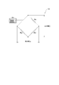
- FIG. 3 is a circuit diagram of an apparatus according to the third embodiment of the first invention.
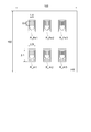
- the first strain gauge R1, the second strain gauge R2, the third strain gauge R3, and the fourth strain gauge R4 of the device 30 according to the third embodiment are attached to a metal object and are attached to a 4-gauge type ( Wheatstone bridge) circuit.
- the linear expansion coefficients of the first and third strain gauges R1 and R3 are larger than the linear expansion coefficient of the metal object, and the linear expansion coefficients of the second and fourth strain gauges R2 and R4 are the linear expansion coefficients of the metal object. Less than the coefficient.
- the metal object is copper
- aluminum strain gauges are used for the first and third strain gauges R1 and R3, and iron strain gauges are used for the second and fourth strain gauges R2 and R4. Is used.
- the thermal strain that is output is further increased. Therefore, in the device 30 according to the third embodiment, the metal object is compared with the device 10 according to the first embodiment and the device 20 according to the second embodiment. Temperature changes can be measured with high sensitivity.
- the first strain gauge R1 and the third strain gauge R3 may be different from each other, and the second strain gauge R2 and the fourth strain gauge R4 may be different from each other.
- the difference between the linear expansion coefficient of the third strain gauges R1 and R3 and the linear expansion coefficient of the metal object is large, and the linear expansion coefficient of the second and fourth strain gauges R2 and R4 and the linear expansion coefficient of the metal object It is preferable that the difference is large.
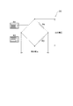
- FIG. 4 is a schematic view of an apparatus according to the first embodiment of the second invention.
- the first strain gauge R1 and the second strain gauge R2 of the device 40 according to the first embodiment are affixed to the plate-like metal object 100 in the xy plane and are two gauges together with fixed resistors R3 and R4 (not shown). Configure an equation (Wheatstone bridge) circuit.
- the grid directions of the first and second strain gauges R1 and R2 are the x direction and coincide with each other.
- the strains detected by the first and second strain gauges R1 and R2 are ⁇ 1 and ⁇ 2, respectively, they are detected by a 2-gauge (Wheatstone bridge) circuit.
- the total strain ⁇ is expressed by Equation 1 below.
- ⁇ ⁇ 1- ⁇ 2 (Formula 1)
- the strain due to the load or the like detected by the first and second strain gauges R1 and R2 is ⁇ 1_s and ⁇ 2_s
- the thermal strain due to the temperature change is ⁇ 1_t.
- ⁇ 2_t the following equation 2 is established.
- Equation 2 ( ⁇ 1_s + ⁇ 1_t) ⁇ ( ⁇ 2_s + ⁇ 2_t) (Formula 2)
- ⁇ 1_s ⁇ 2_s. If this is substituted into Equation 2, the following Equation 3 is established.
- ⁇ ⁇ 1_t ⁇ 2_t (Formula 3)
- Equation 3 As apparent from Equation 3, even if a load or the like is applied to the metal object 100, it is canceled (cancelled), and only the temperature change of the metal object 100 can be detected.
- the linear expansion coefficients of the first and second strain gauges R1 and R2 are different from the linear expansion coefficient of the metal object, and the linear expansion coefficient of the first strain gauge R1 is larger than the linear expansion coefficient of the metal object.
- the linear expansion coefficient of the second strain gauge R2 is smaller than the linear expansion coefficient of the metal object.
- the grid direction of the first strain gauge R1 is perpendicular to the grid direction of the second strain gauge R2, and is pulled by one strain gauge. Strain is detected, and compressive strain is detected by the other strain gauge.
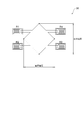
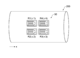
- FIG. 5 is a schematic view of an apparatus according to the second embodiment of the second invention.
- the first strain gauge R1, the second strain gauge R2, the third strain gauge R3, and the fourth strain gauge R4 of the device 50 according to the second embodiment are attached to the side surface of the cylindrical metal object 200.
- ⁇ ⁇ 1- ⁇ 2 + ⁇ 3- ⁇ 4 (Formula 4)
- the load applied to the metal object 200 is canceled out, so that the thermal strain due to the temperature change detected by the first to fourth strain gauges R1 to R4 is reduced.
- ⁇ 1_t to ⁇ 4_t the following Expression 5 is established.
- ⁇ ⁇ 1_t ⁇ 2_t + ⁇ 3_t ⁇ 4_t (Formula 5)
- the linear expansion coefficients of the first to fourth strain gauges R1 to R4 are different from the linear expansion coefficients of the metal object, and the linear expansion coefficients of the first and third strain gauges R1 and R3 are the same as those of the metal object.
- the grid direction of the strain gauge is the x direction, but any direction may be used as long as the grid directions of the plurality of strain gauges match.
- the first sample was three strain gauges R_Fe1, R_Fe2, and R_Fe3 for Fe, and the linear expansion coefficient was set to 11 ppm / ° C.
- the second sample was three Al strain gauges R_Al1, R_Al2, and R_Al3, and the linear expansion coefficient was set to 23 ppm / ° C. As shown by a one-dot chain line in FIG. 7, thermal strain was measured in a temperature cycle of 30 ⁇ 60 ⁇ 90 ⁇ 120 ⁇ 90 ⁇ 60 ⁇ 30 ° C. (each temperature step 3 hours).
- FIG. 7 the measurement result of the thermal strain of each strain gauge accompanying a temperature change is shown collectively.
- the measurement results of the three strain gauges R_Fe1, R_Fe2, and R_Fe3 for Fe are shown by solid lines, the strain on the tensile side is obtained, and the measurement results of the three strain gauges R_Al1, R_Al2, and R_Al3 for Al Are overlapped and indicated by a broken line, and a compressive strain was obtained. It can be seen that each strain follows the temperature change.
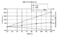
- Table 1 shows the measurement results described above and the calculated output when a 4-gauge (Wheatstone bridge) circuit is configured with two strain gauges for Fe and two strain gauges for Al.
- FIG. 8 shows a temperature-strain (output voltage) curve in which the horizontal axis indicates temperature, the left vertical axis indicates strain, and the right vertical axis indicates voltage output.
- the voltage output was converted from strain by setting 2000 ⁇ to 1 mV.
- the non-linearity is about 4% R.D. O. Hysteresis / return to zero is 0.5% R.D. O. Was less than.
- a strain gauge for Al that has a coefficient of linear expansion greater than that of copper, not a strain gauge for copper that is temperature compensated for the coefficient of linear expansion of copper, and a coefficient of linear expansion that is less than the coefficient of linear expansion of copper.
Landscapes
- Physics & Mathematics (AREA)
- General Physics & Mathematics (AREA)
- Measurement Of Length, Angles, Or The Like Using Electric Or Magnetic Means (AREA)
- Measurement Of Force In General (AREA)
Priority Applications (3)
| Application Number | Priority Date | Filing Date | Title |
|---|---|---|---|
| DE112018002807.0T DE112018002807B4 (de) | 2017-05-30 | 2018-05-17 | Temperaturmessvorrichtung mittels Dehnungsmessstreifen |
| CN201880026721.6A CN110546471B (zh) | 2017-05-30 | 2018-05-17 | 使用应变片的温度测定装置 |
| US16/615,463 US10684176B2 (en) | 2017-05-30 | 2018-05-17 | Temperature measurement device using strain gauge |
Applications Claiming Priority (2)
| Application Number | Priority Date | Filing Date | Title |
|---|---|---|---|
| JP2017-106219 | 2017-05-30 | ||
| JP2017106219A JP6535367B2 (ja) | 2017-05-30 | 2017-05-30 | ひずみゲージを用いた温度測定装置 |
Publications (1)
| Publication Number | Publication Date |
|---|---|
| WO2018221231A1 true WO2018221231A1 (ja) | 2018-12-06 |
Family
ID=64454562
Family Applications (1)
| Application Number | Title | Priority Date | Filing Date |
|---|---|---|---|
| PCT/JP2018/019017 Ceased WO2018221231A1 (ja) | 2017-05-30 | 2018-05-17 | ひずみゲージを用いた温度測定装置 |
Country Status (5)
| Country | Link |
|---|---|
| US (1) | US10684176B2 (enExample) |
| JP (1) | JP6535367B2 (enExample) |
| CN (1) | CN110546471B (enExample) |
| DE (1) | DE112018002807B4 (enExample) |
| WO (1) | WO2018221231A1 (enExample) |
Families Citing this family (5)
| Publication number | Priority date | Publication date | Assignee | Title |
|---|---|---|---|---|
| KR102773587B1 (ko) * | 2019-06-18 | 2025-02-27 | 주식회사 엘지에너지솔루션 | 전지셀 열전도도 측정장치 및 이를 이용한 전지셀 열전도도 측정 방법 |
| JP7390139B2 (ja) * | 2019-09-05 | 2023-12-01 | ミネベアミツミ株式会社 | センサモジュール、ひずみ検出装置 |
| CN114526851B (zh) * | 2022-04-25 | 2022-07-15 | 中国飞机强度研究所 | 一种飞机用金属-复合材料混合结构的热应力的测量方法 |
| CN115856005A (zh) * | 2022-11-18 | 2023-03-28 | 青岛元动芯能源科技有限公司 | 一种液态金属凝固过程中温度应变测量装置 |
| US12270713B2 (en) | 2023-08-23 | 2025-04-08 | Pratt & Whitney Canada Corp. | Heat exchanger differential oil temperature determination |
Citations (2)
| Publication number | Priority date | Publication date | Assignee | Title |
|---|---|---|---|---|
| JPS57103002A (en) * | 1980-12-19 | 1982-06-26 | Nissan Motor Co Ltd | Strain measuring device |
| JPH0495737A (ja) * | 1990-08-06 | 1992-03-27 | Fuji Electric Co Ltd | 電気導体の温度検出装置 |
Family Cites Families (11)
| Publication number | Priority date | Publication date | Assignee | Title |
|---|---|---|---|---|
| US3665756A (en) * | 1965-10-18 | 1972-05-30 | Microdot Inc | Strain gauge temperature compensation system |
| DE2916390C2 (de) * | 1979-04-23 | 1982-05-27 | Siemens AG, 1000 Berlin und 8000 München | Brückenschaltung zur Messung mechanischer Spannungen einer Dehnungsmeßfeder |
| JPH0235367B2 (ja) | 1983-05-18 | 1990-08-09 | Canon Kk | Kogakukeishijisochi |
| JPS6110714A (ja) * | 1984-06-27 | 1986-01-18 | Kyowa Dengiyou:Kk | 測温機能付変換器 |
| JPS6130732A (ja) | 1984-07-24 | 1986-02-13 | Tokyo Sokki Kenkyusho:Kk | ひずみゲ−ジ式変換器による温度測定方法 |
| JPS6134431A (ja) * | 1984-07-26 | 1986-02-18 | Tokyo Sokki Kenkyusho:Kk | ひずみゲ−ジ式変換器による温度測定方法 |
| JP2009210282A (ja) | 2008-02-29 | 2009-09-17 | Nissan Motor Co Ltd | 温度測定装置および温度測定方法並びに温度測定装置の異常検出方法 |
| US8708555B2 (en) * | 2008-03-12 | 2014-04-29 | Alliant Techsystems Inc. | Methods and systems for verifying sensor bond integrity and structures employing such systems |
| CN201465278U (zh) * | 2009-08-26 | 2010-05-12 | 长沙同盛电子科技有限公司 | 远程无线监测系统 |
| CN201653608U (zh) * | 2010-05-07 | 2010-11-24 | 长沙同盛电子科技有限公司 | 高智能电阻应变片式传感器 |
| CN204905842U (zh) * | 2015-08-13 | 2015-12-23 | 广州日滨科技发展有限公司 | 电机过热检测装置 |
-
2017
- 2017-05-30 JP JP2017106219A patent/JP6535367B2/ja active Active
-
2018
- 2018-05-17 DE DE112018002807.0T patent/DE112018002807B4/de active Active
- 2018-05-17 CN CN201880026721.6A patent/CN110546471B/zh active Active
- 2018-05-17 WO PCT/JP2018/019017 patent/WO2018221231A1/ja not_active Ceased
- 2018-05-17 US US16/615,463 patent/US10684176B2/en active Active
Patent Citations (2)
| Publication number | Priority date | Publication date | Assignee | Title |
|---|---|---|---|---|
| JPS57103002A (en) * | 1980-12-19 | 1982-06-26 | Nissan Motor Co Ltd | Strain measuring device |
| JPH0495737A (ja) * | 1990-08-06 | 1992-03-27 | Fuji Electric Co Ltd | 電気導体の温度検出装置 |
Also Published As
| Publication number | Publication date |
|---|---|
| US10684176B2 (en) | 2020-06-16 |
| JP2018200291A (ja) | 2018-12-20 |
| CN110546471A (zh) | 2019-12-06 |
| US20200088587A1 (en) | 2020-03-19 |
| JP6535367B2 (ja) | 2019-06-26 |
| DE112018002807T5 (de) | 2020-04-30 |
| CN110546471B (zh) | 2020-09-22 |
| DE112018002807B4 (de) | 2020-12-10 |
Similar Documents
| Publication | Publication Date | Title |
|---|---|---|
| WO2018221231A1 (ja) | ひずみゲージを用いた温度測定装置 | |
| CN105066870B (zh) | 可测量表面应变轴向偏导的轴向偏差全桥双叉指型金属应变片 | |
| CN106500902B (zh) | 一种具有自解耦功能的应变式多维力传感器 | |
| US11828666B2 (en) | Force measurement device | |
| KR20120043035A (ko) | 변형 게이지 기반의 변환기에서의 회로 보상 | |
| JP2013217763A (ja) | 薄膜ひずみセンサ用材料およびこれを用いた薄膜ひずみセンサ | |
| CN105628269B (zh) | 一种微力及微位移放大传感器 | |
| US20190170566A1 (en) | Load cell having compensation of temperature differences | |
| JP6036151B2 (ja) | 引張試験装置及び引張試験方法 | |
| Jabir et al. | Condition monitoring of the strength and stability of civil structures using thick film ceramic sensors | |
| Pástor et al. | Possibility of using of tensometry in deformation analysis in areas with sudden change of geometry | |
| Qandil et al. | Considerations in the design and manufacturing of a load cell for measuring dynamic compressive loads | |
| Kumar et al. | Design studies and optimization of position of strain gauge | |
| Patel et al. | Validation of experimental strain measurement technique and development of force transducer | |
| Fawcett et al. | The electrical response of thick-film resistors to hydrostatic pressure and uniaxial stress between 77 and 535 K | |
| CN119714657B (zh) | 一种六维力传感器温度漂移测量补偿方法 | |
| Ohgushi et al. | Uncertainty evaluation of the 20 kN m deadweight torque standard machine | |
| CN204924170U (zh) | 可测量表面应变横向偏导的横向偏差全桥全叉指型金属应变片 | |
| Moradkhani et al. | Load cell design and construct with fault detection by Probabilistic Neural Network | |
| Crescini | Load cell for dynamic force measurements: An example in Thick-Film Technology | |
| Bělík et al. | Development of Force Sensor for Linear Guides | |
| JP2023137604A (ja) | ロードセル | |
| Kleckers et al. | High capacity reference transducer for tensile forces | |
| Kleckers | Precise radial symmetric shear beam force transfer transducer for compression force | |
| CN119934953A (zh) | 一种六线制应变测试及电压补偿方法 |
Legal Events
| Date | Code | Title | Description |
|---|---|---|---|
| 121 | Ep: the epo has been informed by wipo that ep was designated in this application |
Ref document number: 18810502 Country of ref document: EP Kind code of ref document: A1 |
|
| 122 | Ep: pct application non-entry in european phase |
Ref document number: 18810502 Country of ref document: EP Kind code of ref document: A1 |