WO2018220935A1 - 蛍光x線分析装置用の試料ホルダ並びに試料ホルダ作成治具及び蛍光x線分析装置用の試料の作製方法 - Google Patents
蛍光x線分析装置用の試料ホルダ並びに試料ホルダ作成治具及び蛍光x線分析装置用の試料の作製方法 Download PDFInfo
- Publication number
- WO2018220935A1 WO2018220935A1 PCT/JP2018/009189 JP2018009189W WO2018220935A1 WO 2018220935 A1 WO2018220935 A1 WO 2018220935A1 JP 2018009189 W JP2018009189 W JP 2018009189W WO 2018220935 A1 WO2018220935 A1 WO 2018220935A1
- Authority
- WO
- WIPO (PCT)
- Prior art keywords
- substrate
- sample holder
- sample
- resin film
- ray
- Prior art date
- Legal status (The legal status is an assumption and is not a legal conclusion. Google has not performed a legal analysis and makes no representation as to the accuracy of the status listed.)
- Ceased
Links
Images







Classifications
-
- G—PHYSICS
- G01—MEASURING; TESTING
- G01N—INVESTIGATING OR ANALYSING MATERIALS BY DETERMINING THEIR CHEMICAL OR PHYSICAL PROPERTIES
- G01N1/00—Sampling; Preparing specimens for investigation
- G01N1/28—Preparing specimens for investigation including physical details of (bio-)chemical methods covered elsewhere, e.g. G01N33/50, C12Q
-
- G—PHYSICS
- G01—MEASURING; TESTING
- G01N—INVESTIGATING OR ANALYSING MATERIALS BY DETERMINING THEIR CHEMICAL OR PHYSICAL PROPERTIES
- G01N23/00—Investigating or analysing materials by the use of wave or particle radiation, e.g. X-rays or neutrons, not covered by groups G01N3/00 – G01N17/00, G01N21/00 or G01N22/00
- G01N23/22—Investigating or analysing materials by the use of wave or particle radiation, e.g. X-rays or neutrons, not covered by groups G01N3/00 – G01N17/00, G01N21/00 or G01N22/00 by measuring secondary emission from the material
- G01N23/223—Investigating or analysing materials by the use of wave or particle radiation, e.g. X-rays or neutrons, not covered by groups G01N3/00 – G01N17/00, G01N21/00 or G01N22/00 by measuring secondary emission from the material by irradiating the sample with X-rays or gamma-rays and by measuring X-ray fluorescence
Definitions
- the present invention relates to a sample holder for a fluorescent X-ray analyzer, a sample holder preparation jig, and a method for preparing a sample for a fluorescent X-ray analyzer.
- the measurement object is not limited to a solid sample, but may be a liquid sample, that is, a sample having fluidity.
- Patent Document 1 discloses a fluid sample and a measurement method. Specifically, first, a fluid sample is filled in a recess formed by a support substrate having a hole in the bottom surface and a resin film attached so as to close the hole. Next, it is disclosed that a porous film is disposed so as to cover the surface of the filled sample.
- a liquid sample is a measurement target
- a top-illuminated X-ray fluorescence analyzer in which an X-ray tube, a detector, and the like are arranged on the upper side of the sample is used.
- a method is known in which a liquid sample is filled in a container having a bubble reservoir, and a sample in which bubbles are not positioned on the measurement surface is analyzed using a fluorescent X-ray analyzer for top surface irradiation.
- a method is also known in which a liquid sample is measured after being drip-dried.
- a method of performing fluorescent X-ray analysis in a state where a liquid sample dropped on a filter paper is dried is known.
- the measurement sample described in Patent Document 1 uses a porous film. Therefore, when the filled sample is low-viscosity or volatile, the sample passes through the pores of the porous film and cannot be measured.
- the drip drying method in which the fluorescent X-ray analysis is performed after the liquid sample dropped on the filter paper is dried cannot be applied if the liquid is a material that does not dry.
- the present invention has been made in view of the above problems, and its purpose is to measure a small amount of a liquid sample that cannot be drip-dried when measuring with a top-illuminated X-ray fluorescence analyzer.
- a sample holder for a fluorescent X-ray analyzer is provided on a surface of a support substrate having a hole in which a liquid sample is arranged and an X-ray incident side surface of the support substrate so as to cover the hole.
- the sample holder according to claim 2 is the sample holder according to claim 1, wherein the fixed substrate has flexibility.
- the sample holder according to claim 3 is the sample holder according to claim 2, wherein the fixed substrate is thinner than the support substrate.
- the sample holder according to claim 4 is the sample holder according to any one of claims 1 to 3, wherein the adhesive layer that adheres the first substrate and the second substrate is an adhesive and a third resin film. And a paste is laminated and formed.
- the sample holder according to claim 5 is the sample holder according to any of claims 1 to 4, wherein the X-ray fluorescence analyzer is a top-illuminated X-ray fluorescence analyzer.
- the sample holder according to claim 6 is the sample holder according to any one of claims 1 to 5, wherein the support substrate and the fixed substrate are different in color.
- the sample holder according to claim 7 is the sample holder according to any one of claims 1 to 6, wherein the first resin film and the second resin film are formed of polypropylene, polyester, or polyimide. To do.
- the sample holder according to claim 8 is the sample holder according to any one of claims 1 to 7, wherein the third resin film is formed of a foam.
- a sample holder creation jig according to claim 9 is a sample holder creation jig for creating the sample holder according to any one of claims 1 to 8, and is a part of the outer shape of the first substrate. And the flat plate portion on which the first substrate is placed, and the first substrate of the flat plate portion is placed along an edge of a portion corresponding to the outer shape. And a guide portion for fixing the first substrate that is erected with respect to the surface to be fixed.
- the sample holder creation jig according to claim 10 is characterized in that in the sample holder creation jig according to claim 9, the flat plate portion has an index indicating an extension of the hole of the support substrate.
- the sample holder preparation jig according to claim 11 is the sample holder preparation jig according to claim 9 or 10, characterized in that it is formed of polyethylene terephthalate.
- a method for preparing a sample for a fluorescent X-ray analyzer comprising: a support substrate having holes; and a first resin bonded to a surface on the X-ray incident side of the support substrate so as to cover the holes.
- the method for preparing a sample for a fluorescent X-ray analyzer according to claim 13 is the method for preparing a sample for a fluorescent X-ray analyzer according to claim 12, further comprising a part of the outer shape of the first substrate. And the flat plate portion on which the first substrate is placed, and the first substrate of the flat plate portion is placed along an edge of a portion corresponding to the outer shape. Including a step of placing the first substrate on a sample holder creating jig having a guide portion for fixing the first substrate standing on a surface to be fixed.
- a small amount of liquid sample that cannot be drip-dried can be measured with a top-illuminated X-ray fluorescence analyzer.
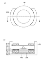
- FIG. 1 schematically shows a sample holder 100 according to the present invention.
- FIG. 1A is a view showing a cross section of the sample holder 100
- FIG. 1B is a view of the sample holder 100 as viewed from above.
- the sample holder 100 includes a first substrate 102 and a second substrate 104.
- the first substrate 102 includes a support substrate 106, a first resin film 108, an adhesive layer 110, and a glue 114.
- the support substrate 106 is a disc-shaped substrate having a diameter of 50 mm, and a circular hole 112 having a diameter of 32 mm is provided at the center.
- the liquid sample 200 is disposed in a recess formed by the hole 112 of the support substrate 106 and the first resin film 108 bonded to the support substrate 106.
- the support substrate 106 is made of, for example, polycarbonate, polypropylene, or polyethylene terephthalate having a thickness of 0.5 to 2 mm.
- the first resin film 108 is bonded to the surface on the X-ray incident side of the support substrate 106 so as to cover the hole 112. Specifically, the first resin film 108 is bonded to the surface on the X-ray incident side of the support substrate 106 with a glue 114 so as to block the holes 112 provided in the support substrate 106.
- the glue 114 is preferably formed in the same configuration as the adhesive layer 110.
- the first resin film 108 is formed of a thin resin having a thickness of 0.1 to 25 ⁇ m having high X-ray transmittance, airtightness and liquid tightness.
- the first resin film 108 is formed of polypropylene, polyester, or polyimide having a thickness of 6 ⁇ m. Since the first resin film 108 has air tightness and liquid tightness, the measurement by the fluorescent X-ray analyzer 1300 can be performed with the liquid sample sealed. Further, by forming the first resin film 108 with a thin resin, it is possible to reduce the influence of scattered rays included in the measurement result by the fluorescent X-ray analyzer 1300 and to measure with high sensitivity and high accuracy.
- the first resin film 108 is formed of a resin having transparency. If the first resin film 108 is transparent or translucent, it can be visually recognized from the outside whether or not bubbles are mixed in the liquid sample 200.
- the adhesive layer 110 is formed by laminating the adhesive 114, the third resin film 116, and the adhesive 114, and adheres the first substrate 102 and the second substrate 104 to each other.
- the adhesive layer 110 is a double-sided tape in which a paste 114 is attached to the front surface and the back surface of the core material.
- the third resin film 116 that is a core material is formed of, for example, a foamed material such as polyolefin to which foaming property that suppresses permeation of the liquid sample 200 is added. Accordingly, it is possible to prevent the liquid sample 200 from bleeding from the interface between the first substrate 102 and the second substrate 104 after the first substrate 102 and the second substrate 104 are bonded to each other.
- the adhesive layer 110 is provided with a release paper that protects the surface of the adhesive 114 before the first substrate 102 and the second substrate 104 are bonded together.
- the release paper is peeled before bonding the first substrate 102 and the second substrate 104 together.
- the second substrate 104 includes a fixed substrate 118, a second resin film 120, and a paste 114.
- the fixed substrate 118 has holes 122 at positions corresponding to the holes 112 of the support substrate 106.
- the fixed substrate 118 is a disc-shaped substrate having a diameter of 50 mm, and a circular hole 122 having a diameter of 32 mm is formed in the central portion in the same manner as the support substrate 106. Is provided.
- FIG. 1A it is desirable that the positions and sizes of the holes 112 provided in the support substrate 106 and the holes 122 provided in the fixed substrate 118 coincide with each other after being bonded.
- the fixed substrate 118 has flexibility.
- the fixed substrate 118 may be formed of polycarbonate, polypropylene, or polyethylene terephthalate having a high flexibility and a thickness of 0.5 to 1.5 mm, or more flexible than the material. It may be formed of a high material.
- the fixed substrate 118 may be formed thinner than the support substrate 106 so as to increase flexibility. Specifically, for example, the thickness of the fixed substrate 118 is 0.5 mm, and the thickness of the support substrate 106 is 0.8 mm.
- the support substrate 106 and the fixed substrate 118 are formed in different colors. Specifically, for example, the support substrate 106 is formed in white, while the fixed substrate 118 is formed in black. By making the support substrate 106 and the fixed substrate 118 different colors, the measurement surface can be easily identified.
- the second resin film 120 is bonded to the surface on the X-ray incident side of the fixed substrate 118. Specifically, the second resin film 120 is adhered to the surface on the X-ray incident side of the fixed substrate 118 with an adhesive so as to block the hole 122 provided in the fixed substrate 118.
- the surface on the X-ray incident side is a surface to be bonded to the first substrate 102.
- the second resin film 120 is formed of a thin resin having a thickness of 0.1 to 25 ⁇ m and having air tightness and liquid tightness. Specifically, the second resin film 120 is formed with a thickness of 6 ⁇ m from polypropylene, polyester, or polyimide, similarly to the first resin film 108. Since the second resin film 120 has air tightness and liquid tightness, the measurement by the fluorescent X-ray analyzer 1300 can be performed with the liquid sample sealed. In addition, by forming the second resin film 120 with a thin resin, it is possible to reduce the influence of scattered rays included in the measurement result by the fluorescent X-ray analyzer 1300 and perform measurement with high accuracy.
- the second resin film 120 is bonded to the first substrate 102 so as to cover the opening surface of the recess formed by the support substrate 106 and the first resin film 108. Thereby, the 2nd resin film 120 seals the liquid sample 200 with which the said recessed part was filled.
- FIG. 1 shows a configuration in which only the glue 114 is provided between the fixed substrate 118 and the second resin film 120.
- a configuration in which the adhesive 114, the third resin film 116, and the adhesive 114 are stacked is provided between the fixed substrate 118 and the second resin film 120 in the same manner as the adhesive layer 110. desirable.
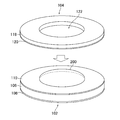
- FIG. 6 is a diagram showing a step of dropping a liquid sample 200 into a recess formed by the hole 112 and the first resin film 108 with respect to a first substrate 102 having a hole.
- the first substrate 102 is disposed on a clean flat surface with the first resin film 108 of the first substrate 102 facing down.
- the liquid sample 200 which is a measuring object is dripped at a recessed part.
- the diameter of the recess is 32 mm and the thickness of the support substrate 106 is 0.8 mm, about 1 mL of sample is dropped.
- FIG. 3 is a diagram showing the first substrate 102 after the liquid sample 200 is dropped. As shown in FIG. 3, the sample is dropped by surface tension so that the surface of the sample is slightly higher than the surface of the adhesive layer 110 provided on the first substrate 102. Then, although omitted in FIG. 3, the release paper attached to the surface of the adhesive layer 110 is peeled off, and the glue 114 is exposed.
- the masses of the support substrate 106 and the fixed substrate 118 from which the release paper has been peeled are measured in advance, and are subtracted from the mass of the sample holder 100 filled with the sample 200 to calculate the mass of the filled sample 200. It can be used for correction of line analysis.
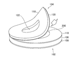
- FIG. 4 to 6 show a fixed substrate 118 having a hole 122 at a position corresponding to the hole 112 of the support substrate 106, a second resin film 120 bonded to the surface on the X-ray incident side of the fixed substrate 118, It is a figure which shows the process of bonding the 2nd board
- the second substrate 104 is bonded to the first substrate 102 onto which the sample is dropped with the surface to which the second resin film 120 is bonded facing the first substrate 102.
- the fixed substrate 118 has flexibility. Therefore, as shown in FIG. 5, after the second substrate 104 is made to have a convex shape with respect to the first substrate 102 and the edges are aligned, the second substrate 104 is gradually bonded to the sample. Bubbles to be mixed can be reduced.
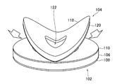
- a liquid sample that is slightly higher than the surface of the adhesive layer 110 by causing both ends of the second substrate 104 to have a bow shape so as to be convex with respect to the first substrate 102.
- the second substrate 104 may be gradually bonded from the vicinity of the center line that hits the diameter toward both ends from a state in which the center portion of 200 and the center portion of the second resin film 120 are in contact with each other. Thereby, bubbles mixed in the sample can be reduced.
- the second resin film 120 is made of a transparent resin. If the second resin film 120 is transparent or translucent, the liquid sample 200 can be attached while being visually recognized so that no bubbles are mixed therein.
- FIG. 7 is a diagram showing the sample holder 100 in a state where the first substrate 102 and the second substrate 104 are bonded together after the sample is filled. Since the first substrate 102 and the second substrate 104 are bonded together in a state where the first substrate 102 is disposed on a flat surface, the first resin film 108 is flattened even when the sample is filled. .
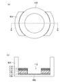
- FIG. 8A is a view of the sample holder creation jig 800 as viewed from the top
- FIG. 8B is a view of the sample holder creation jig 800 as viewed from the side.
- the sample holder creation jig 800 has a flat plate portion 802 and a guide portion 804.
- the flat plate portion 802 has a planar shape having the same outer shape as a part of the outer shape of the first substrate 102, and the first substrate 102 is placed thereon. Specifically, the flat plate portion 802 has a planar shape having an outer shape in which a part of the first substrate 102 having a circular outer shape is cut out. For example, as shown in FIG. 8A, the flat plate portion 802 has a shape in which an upper region and a lower region that are the same distance away from the center of the first substrate 102 in the drawing are cut out. Further, as will be described later, the first substrate 102 is placed on the flat plate portion 802 so that the surface of the first substrate 102 on which the first resin film 108 is provided is in contact.
- the flat plate portion 802 may have an index 806 indicating the extension of the hole 112 of the support substrate 106.
- an index 806 such as a marking line or a pattern may be provided at a position corresponding to the extension of the hole 112 of the support substrate 106.
- the guide portion 804 fixes the first substrate 102 erected with respect to the surface on which the first substrate 102 of the flat plate portion 802 is placed along the edge of the portion corresponding to the outer shape. Specifically, as shown in FIG. 8A, the guide portion 804 is located on the surface of the flat plate portion 802 on which the first substrate 102 is placed along the edge of the arc-shaped portion of the flat plate portion 802. It is formed vertically.
- the guide portion 804 has a gap between the inner side surface of the guide portion 804 and the outer side surface of the first substrate 102 in order to fix the first substrate 102 when the first substrate 102 is placed on the flat plate portion 802. It is desirable to be within 1 mm.
- FIG. 9 to 12 are diagrams showing a process of filling the sample holder 100 with the sample 200 using the sample holder creation jig 800.
- FIG. 9 to 12 are diagrams showing a process of filling the sample holder 100 with the sample 200 using the sample holder creation jig 800.
- the surface on which the first substrate 102 of the flat plate portion 802 is placed is cleaned.
- the flat plate portion 802 is provided with the index 806, the position corresponding to the region filled with the sample 200 to be measured becomes clear. Therefore, by cleaning the inside of the index 806, it is possible to prevent a decrease in measurement accuracy due to adhesion of impurities.
- FIG. 9A is a view showing a IX-IX cross section of FIG.
- the first substrate 102 is placed such that the first resin film 108 is in contact with the flat plate portion 802.
- FIG. 9B shows a state in which the release paper attached to the surface of the adhesive layer 110 has been peeled off and the glue 114 has been exposed.
- FIGS. 10 (a) and 10 (b) a liquid sample 200 to be measured is dropped into the recess.
- the method of dropping the sample 200 is the same as the method shown in FIG.
- FIG. 10B is a diagram showing a cross section taken along the line XX of FIG.
- FIG. 11B is a view showing a XI-XI cross section of FIG.
- the surface of the sample 200 is slightly higher than the surface of the adhesive layer provided on the first substrate 102 due to surface tension. It has become.
- the second substrate 104 is bonded to the first substrate 102 onto which the sample 200 is dropped with the surface to which the second resin film 120 is bonded facing the first substrate 102.
- the first substrate 102 and the second substrate 104 have the same planar outline.
- the first substrate 102 and the second substrate 104 are bonded together by the guide portion 804 so that the centers thereof coincide.
- the second substrate 104 is formed in a bow shape so as to be convex with respect to the first substrate 102 so that bubbles are not mixed into the sample 200, and then the second substrate 104 is aligned.
- the substrate 104 may be attached gradually.
- both ends of the second substrate 104 are bowed so as to be convex with respect to the first substrate 102, so that the liquid state is slightly higher than the surface of the adhesive layer.
- the second substrate 104 may be gradually bonded from the vicinity of the center line corresponding to the diameter toward both ends from the state in which the center portion of the sample 200 and the center portion of the second resin film 120 are in contact with each other.
- FIGS. 12A and 12B are diagrams showing the sample holder 100 in a state where the first substrate 102 and the second substrate 104 are bonded together after the sample 200 is filled.
- FIG. 12B is a view showing a cross section taken along line XII-XII in FIG. As shown in FIG. 12B, the first substrate 102 and the second substrate 104 are bonded so that their centers coincide.
- the sample holder 100 is mounted on the fluorescent X-ray analyzer 1300, it is possible to prevent the sample holder 100 from being fitted to the sample stage 1302 of the X-ray analyzer.
- a recess for placing the sample holder 100 is provided on the sample stage 1302, it is possible to prevent a situation in which the sample holder 100 is not fitted in the recess.
- the X-ray fluorescence analyzer 1300 is a top-illuminated X-ray fluorescence analyzer 1300, but since the X-ray fluorescence analyzer 1300 itself is the same as the prior art, detailed description thereof is omitted.
- the X-ray fluorescence analyzer 1300 includes a sample stage 1302, an X-ray source 1304, a detector 1306, a counter 1308, and an analyzer 1310. On the sample stage 1302, a sample to be measured is placed. Specifically, as shown in FIG. 13, the sample holder 100 filled with the liquid sample 200 is placed on the sample stage 1302 with the first resin film 108 bonded to the first substrate 102 facing upward. Is done.
- the X-ray source 1304 irradiates the surface of the sample holder 100 with primary X-rays that generate fluorescent X-rays. Specifically, the X-ray source 1304 irradiates the central portion of the first resin film 108 of the sample holder 100 with primary X-rays. The liquid sample 200 irradiated with secondary X-rays emits secondary X-rays.
- the sample holder 100 filled with the liquid sample 200 and sealed with the thin first resin film 108 and the second resin film 120 may be ruptured under vacuum. Therefore, the measurement is performed under normal pressure.
- measurement is performed under helium purge to reduce X-ray absorption in the optical path of the optical system.
- the detector 1306 is a detector 1306 such as an SDD.
- the detector 1306 measures the intensity of the secondary X-ray and outputs a pulse signal having a peak value corresponding to the measured energy of the secondary X-ray.
- the counter 1308 counts the pulse signal output as the measurement intensity of the detector 1306 according to the peak value.
- the counter 1308 is a multi-channel analyzer, and counts the output pulse signal of the detector 1306 for each channel corresponding to the energy of the secondary X-ray, and the intensity of the secondary X-ray. Output as.
- the counter 1308 that acquires the output of the detector 1306 that measures the split secondary X-rays is a pulse signal only in the peak value range corresponding to the split energy. It may be a single channel analyzer that counts.
- the analysis unit 1310 quantitatively analyzes the elements contained in the sample from the counting result of the counter 1308. Specifically, for example, the analysis unit 1310 performs a quantitative analysis by a calibration curve method or an FP (fundamental parameter) method using the count result of the counter 1308.
- a liquid sample 200 that cannot be drip-dried in a small amount can be measured with the top-illuminated X-ray fluorescence analyzer 1300.
- the present invention is not limited to the above-described embodiments, and various modifications can be made.
- the configuration of the X-ray fluorescence analyzer 1300 is an example, and the present invention is not limited to this. It may be replaced with a configuration that is substantially the same as the configuration shown in the above embodiment, a configuration that exhibits the same operational effects, or a configuration that achieves the same purpose.
- the sample holder 100 according to the present invention is placed such that the first resin film 108 is on the lower side, and an X-ray tube, a detector, and the like are disposed on the lower side of the sample. It can also be measured using an apparatus.
- Sample holder 102 First substrate, 104 Second substrate, 106 Support substrate, 108 First resin film, 110 Adhesive layer, 112 Support substrate hole, 114 Glue, 116 Third resin film, 118 Fixed substrate, 120th 2 resin film, 122 hole of fixed substrate, 200 liquid sample, 800 sample holder creation jig, 802 flat plate part, 804 guide part, 806 index, 1300 fluorescent X-ray analyzer, 1302 sample stage, 1304 X-ray source, 1306 detector, 1308 counter, 1310 analysis unit.
Landscapes
- Physics & Mathematics (AREA)
- Health & Medical Sciences (AREA)
- Life Sciences & Earth Sciences (AREA)
- Chemical & Material Sciences (AREA)
- Analytical Chemistry (AREA)
- Biochemistry (AREA)
- General Health & Medical Sciences (AREA)
- General Physics & Mathematics (AREA)
- Immunology (AREA)
- Pathology (AREA)
- Analysing Materials By The Use Of Radiation (AREA)
Abstract
上面照射型の蛍光X線分析装置で測定を行う場合に、少量かつ点滴乾燥することのできない液体状の試料の測定を可能とする蛍光X線分析装置用の試料ホルダを提供する。蛍光X線分析装置用の試料ホルダは、液体状の試料が配置される孔(112)を有する支持基板(106)と、該孔を覆うように該支持基板のX線の入射側の面に接着された第1樹脂フィルム(108)と、支持基板の第1樹脂フィルムが接着された面の裏面に設けられた接着層(110)と、を有する第1基板(102)と、前記支持基板が有する孔と対応する位置に孔(122)を有する固定基板(118)と、該固定基板の前記X線の入射側の面に接着された第2樹脂フィルム(120)と、を有し、前記接着層によって前記第1基板と接着される第2基板(104)と、を有する。
Description
本発明は、蛍光X線分析装置用の試料ホルダ並びに試料ホルダ作成治具及び蛍光X線分析装置用の試料の作製方法、に関する。
測定対象となる試料にX線を照射し、出射された蛍光X線に基づいて試料に含まれる元素を検出する蛍光X線分析装置が知られている。測定対象は、固形状の試料に限られず、液体状、すなわち流動性を有する試料の場合もある。
例えば、特許文献1は、流動性を有する試料及び測定方法を開示している。具体的には、まず、底面に孔の開いた支持基板と、その孔を塞ぐように張り付けられた樹脂フィルムと、によって形成される凹部に流動性を有する試料が充填される。次に、その充填された試料の表面を覆うように多孔質フィルムが配置される点が開示されている。
また、蛍光X線分析装置のX線管や検出器等が試料の下側に配置されている場合、液体状の試料が測定中に測定容器からこぼれると蛍光X線分析装置の深刻な故障の原因となる。そのため、液体状の試料が測定対象である場合、X線管や検出器等が試料の上側に配置された上面照射型の蛍光X線分析装置が用いられる。例えば、気泡溜めを有する容器に液体の試料を充填し、気泡が測定面に位置しないようにされた試料を、上面照射用の蛍光X線分析装置を用いて分析する方法が知られている。
さらに、液体状の試料を点滴乾燥させてから測定する方法も知られている。例えば、濾紙に滴下した液体の試料を乾燥させた状態で蛍光X線分析を行う方法が知られている。
上記特許文献1に記載された測定用試料は、多孔質フィルムが用いられている。その為、充填された試料が低粘性や揮発性である場合、試料が多孔質フィルムの孔を通り抜けてしまい、測定することができない。
また、気泡溜めを有する容器に液体状の試料を充填する場合、気泡が測定面に位置しないようにするために一定の体積より多くの試料が必要である。その為、当該容器を用いて蛍光X線分析を行う方法は、試料が少量しかない場合には適用できない。
さらに、濾紙に滴下された液体の試料を乾燥させた後で蛍光X線分析を行う点滴乾燥法は、液体が乾燥しない材質である場合、適用することができない。
本発明は上記課題に鑑みてなされたものであって、その目的は、上面照射型の蛍光X線分析装置で測定を行う場合に、少量かつ点滴乾燥することのできない液体状の試料の測定を可能とする蛍光X線分析装置用の試料ホルダ及び蛍光X線分析装置用の試料の作製方法を提供することである。
請求項1に記載の蛍光X線分析装置用の試料ホルダは、液体状の試料が配置される孔を有する支持基板と、該孔を覆うように該支持基板のX線の入射側の面に接着された第1樹脂フィルムと、該支持基板の該第1樹脂フィルムが接着された面の裏面に設けられた接着層と、を有する第1基板と、前記支持基板が有する孔と対応する位置に孔を有する固定基板と、該固定基板の前記X線の入射側の面に接着された第2樹脂フィルムと、を有し、前記接着層によって前記第1基板と接着される第2基板と、を有することを特徴とする。
請求項2に記載の試料ホルダは、請求項1に記載の試料ホルダにおいて、前記固定基板は、可撓性を有することを特徴とする。
請求項3に記載の試料ホルダは、請求項2に記載の試料ホルダにおいて、前記固定基板は、前記支持基板よりも薄いことを特徴とする。
請求項4に記載の試料ホルダは、請求項1乃至3のいずれかに記載の試料ホルダにおいて、前記第1基板と、前記第2基板を接着する接着層は、糊剤と、第3樹脂フィルムと、糊剤が積層されて形成されることを特徴とする。
請求項5に記載の試料ホルダは、請求項1乃至4のいずれかに記載の試料ホルダにおいて、前記蛍光X線分析装置は、上面照射型の蛍光X線分析装置であることを特徴とする。
請求項6に記載の試料ホルダは、請求項1乃至5のいずれかに記載の試料ホルダにおいて、前記支持基板と前記固定基板は、色が異なることを特徴とする。
請求項7に記載の試料ホルダは、請求項1乃至6のいずれかに記載の試料ホルダにおいて、前記第1樹脂フィルム及び第2樹脂フィルムは、ポリプロピレン、ポリエステルまたはポリイミドで形成されることを特徴とする。
請求項8に記載の試料ホルダは、請求項1乃至7のいずれかに記載の試料ホルダにおいて、前記第3樹脂フィルムは、発泡体で形成されることを特徴とする。
請求項9に記載の試料ホルダ作成治具は、請求項1乃至8のいずれかに記載の試料ホルダを作成する為の試料ホルダ作成治具であって、前記第1基板の外形状の一部と同じ外形状を有する平面形状であって、前記第1基板が載置される平板部と、前記外形状に対応する部分の縁に沿って、前記平板部の前記第1基板が載置される面に対して立設される前記第1基板を固定するガイド部と、を有することを特徴とする。
請求項10に記載の試料ホルダ作成治具は、請求項9に記載の試料ホルダ作成治具において、前記平板部は、前記支持基板の前記孔の外延を示す指標を有することを特徴とする。
請求項11に記載の試料ホルダ作成治具は、請求項9または10に記載の試料ホルダ作成治具において、ポリエチレンテレフタラートで形成されることを特徴とする。
請求項12に記載の蛍光X線分析装置用の試料の作製方法は、孔を有する支持基板と、該孔を覆うように該支持基板のX線の入射側の面に接着された第1樹脂フィルムと、該支持基板の該第1樹脂フィルムが接着された面の裏面に設けられた接着層と、を有する第1基板に対して、該孔と前記第1樹脂フィルムで形成される凹部に液体状の試料を滴下する工程と、前記支持基板が有する孔と対応する位置に孔を有する固定基板と、該固定基板の前記X線の入射側の面に接着された第2樹脂フィルムと、を有する第2基板を、前記接着層によって前記第1基板に貼り合せる工程と、を有することを特徴とする。
請求項13に記載の蛍光X線分析装置用の試料の作製方法は、請求項12に記載の蛍光X線分析装置用の試料の作製方法において、さらに、前記第1基板の外形状の一部と同じ外形状を有する平面形状であって、前記第1基板が載置される平板部と、前記外形状に対応する部分の縁に沿って、前記平板部の前記第1基板が載置される面に対して立設される前記第1基板を固定するガイド部と、を有する試料ホルダ作成治具に、前記第1基板を載置する工程を含むことを特徴とする。
請求項1及び5乃至12に記載の発明によれば、少量かつ点滴乾燥することのできない液体状の試料を、上面照射型の蛍光X線分析装置で測定できる。
また、請求項2及び3に記載の発明によれば、試料を試料ホルダに充填する際に、混入する気泡を少なくすることが出来る。
また、請求項4に記載の発明によれば、充填した液体状の試料が試料ホルダの外部に滲み出ることを防止できる。
また、請求項9乃至11及び13に記載の発明によれば、試料ホルダの作成精度を向上することができる。
以下、本発明を実施するための好適な実施の形態(以下、実施形態という)を説明する。図1は本発明に係る試料ホルダ100を概略的に示す図である。図1(a)は、試料ホルダ100の断面を示す図であり、図1(b)は、試料ホルダ100を上側から見た図である。
図1に示すように、試料ホルダ100は、第1基板102と、第2基板104と、を有する。第1基板102は、支持基板106と、第1樹脂フィルム108と、接着層110と、糊剤114と、を有する。
支持基板106は、例えば図1(b)に示すように、直径50mmの円板状の基板であって、中央部に直径32mmの円形状の孔112が設けられる。液体状の試料200は、支持基板106の孔112と、支持基板106に接着された第1樹脂フィルム108と、によって形成される凹部に配置される。支持基板106は、例えば、厚さ0.5~2mmのポリカーボネート、ポリプロピレンまたはポリエチレンテレフタレート等で形成される。
第1樹脂フィルム108は、該孔112を覆うように支持基板106のX線の入射側の面に接着される。具体的には、第1樹脂フィルム108は、支持基板106に設けられた孔112をふさぐように、支持基板106のX線の入射側の面に糊剤114で接着される。当該糊剤114は、接着層110と同じ構成で形成されるのが望ましい。
また、第1樹脂フィルム108は、X線透過率が高く、気密性及び液密性を有する厚さ0.1~25μmの薄い樹脂で形成される。具体的には、例えば、第1樹脂フィルム108は、6μmの厚さのポリプロピレン、ポリエステルまたはポリイミドで形成される。第1樹脂フィルム108が気密性及び液密性を有することで、液体試料を密閉した状態で蛍光X線分析装置1300による測定を行うことができる。また、第1樹脂フィルム108を薄い樹脂で形成することで、蛍光X線分析装置1300による測定結果に含まれる散乱線の影響を低減し、高感度かつ高精度に測定することができる。
また、第1樹脂フィルム108は、透明性を有する樹脂で形成される。第1樹脂フィルム108が透明または半透明であれば、液体状の試料200に気泡が混入したか否かを外部から視認できる。
接着層110は、糊剤114と、第3樹脂フィルム116と、糊剤114が積層されて形成され、第1基板102と、第2基板104を接着する。具体的には、例えば、接着層110は、芯材の表面と裏面に糊剤114が付された両面テープである。芯材である第3樹脂フィルム116は、例えば、液体状の試料200の浸透を抑制する発泡性を付加したポリオレフィン等の発泡体で形成される。これにより、第1基板102と第2基板104が貼り合わされた後で、液体状の試料200が、第1基板102と第2基板104の界面からにじみ出ることを防止できる。
接着層110は、第1基板102と第2基板104が貼り合せられる前の状態では、糊剤114の表面を保護する剥離紙が付される。当該剥離紙は、第1基板102と第2基板104を貼り合せる前に剥離される。
第2基板104は、固定基板118と、第2樹脂フィルム120と、糊剤114と、を有する。固定基板118は、支持基板106が有する孔112と対応する位置に孔122を有する。具体的には、例えば図1(b)に示すように、固定基板118は、直径50mmの円板状の基板であって、支持基板106と同様に中央部に直径32mmの円形状の孔122が設けられる。なお、図1(a)に示すように、支持基板106に設けられる孔112と固定基板118に設けられる孔122の位置及び大きさは、貼り合せられた後に一致することが望ましい。
固定基板118は、可撓性を有する。具体的には、例えば、固定基板118は、高い可撓性を有する、厚さ0.5~1.5mmのポリカーボネート、ポリプロピレンまたはポリエチレンテレフタレートで形成されてもよいし、当該材料よりも可撓性の高い材料で形成されてもよい。可撓性が高くなるように、固定基板118は、支持基板106よりも薄く形成されてもよい。具体的には、例えば、固定基板118の厚さは0.5mmであり、支持基板106の厚さは0.8mmである。
支持基板106と固定基板118は、異なる色で形成される。具体的には、例えば、支持基板106が白色で形成されるのに対して、固定基板118は黒色で形成される。支持基板106と固定基板118とを異なる色にすることで、測定面を容易に識別できる。
第2樹脂フィルム120は、固定基板118のX線の入射側の面に接着される。具体的には、第2樹脂フィルム120は、固定基板118に設けられた孔122をふさぐように、固定基板118のX線の入射側の面に接着剤で接着される。X線の入射側の面は、第1基板102と貼り合せられる面である。
また、第2樹脂フィルム120は、気密性及び液密性を有する厚さ0.1~25μmの薄い樹脂で形成される。具体的には、第2樹脂フィルム120は、第1樹脂フィルム108と同様に、ポリプロピレン、ポリエステルまたはポリイミドによって、6μmの厚さで形成される。第2樹脂フィルム120が気密性及び液密性を有することで、液体試料を密閉した状態で蛍光X線分析装置1300による測定を行うことができる。また、第2樹脂フィルム120を薄い樹脂で形成することで、蛍光X線分析装置1300による測定結果に含まれる散乱線の影響を低減し、高精度に測定することができる。
第2樹脂フィルム120は、支持基板106と第1樹脂フィルム108とで形成される凹部の開口面を覆うように第1基板102に貼り合わされる。これにより、第2樹脂フィルム120は、当該凹部に充填された液体状の試料200を密閉する。
第2基板104に設けられた糊剤114は、固定基板118と第2樹脂フィルム120を貼り合せる。なお、図1は、固定基板118と第2樹脂フィルム120の間に糊剤114のみが設けられる構成を記載している。しかし、固定基板118と第2樹脂フィルム120の間に、接着層110と同じように、糊剤114と、第3樹脂フィルム116と、糊剤114とが積層された構成が設けられることがより望ましい。
続いて、上記試料ホルダ100に液体状の試料200を充填し、蛍光X線分析装置1300用の試料を作製する方法について説明する。図2及び図3は、孔112を有する支持基板106と、該孔112を覆うように支持基板106のX線の入射側の面に接着された第1樹脂フィルム108と、接着層110と、を有する第1基板102に対して、該孔112と第1樹脂フィルム108で形成される凹部に液体状の試料200を滴下する工程を示す図である。
具体的には、まず、図2に示すように、第1基板102は、清浄な平らな面に、第1基板102の第1樹脂フィルム108を下に向けた状態で配置される。そして、測定対象である液体状の試料200が、凹部に滴下される。例えば、凹部の直径が32mmであり、支持基板106の厚さが0.8mmである場合、約1mLの試料が滴下される。
図3は、液体状の試料200が滴下された後の第1基板102を示す図である。図3に示すように、試料は、表面張力によって、試料の表面が第1基板102に設けられた接着層110の表面よりも少し高い位置となるように滴下される。そして、図3では省略しているが、接着層110の表面に付された剥離紙が剥離され、糊剤114が露出する。
滴下した試料200を零さないよう、剥離紙は、試料を滴下する前に剥離しておくのが望ましい。また、剥離紙を剥離した支持基板106と固定基板118の質量を予め測定しておき、試料200を充填した試料ホルダ100の質量から差し引いて、充填された試料200の質量を算出し、蛍光X線分析の補正に用いることができる。
図4乃至図6は、支持基板106が有する孔112と対応する位置に孔122を有する固定基板118と、固定基板118のX線の入射側の面に接着された第2樹脂フィルム120と、を有する第2基板104を、接着層110によって第1基板102に貼り合せる工程を示す図である。
図4に示すように、試料が滴下された第1基板102に対して、第2樹脂フィルム120が接着された面を第1基板102に向けて、第2基板104が貼り合わされる。固定基板118は、可撓性を有する。そのため、図5に示すように、第1基板102に対して凸面になるよう第2基板104を弓状にしならせて縁を合わせた後、第2基板104を徐々に貼り合せることで試料に混入する気泡を低減できる。
また、図6に示すように、第1基板102に対して凸面になるよう第2基板104の両端を弓状にしならせて、接着層110の表面よりも少し高い位置となる液体状の試料200の中央部と、第2樹脂フィルム120の中央部と、を接触させた状態から、第2基板104を直径に当たる中央線付近から両端に向けて徐々に貼り合せてもよい。これにより、試料に混入する気泡を低減できる。
第2樹脂フィルム120は、透明性を有する樹脂で形成される。第2樹脂フィルム120が透明または半透明であれば、液体状の試料200に気泡が混入しないように視認しながら張り合わせることができる。
図7は、試料が充填された後、第1基板102と第2基板104が貼り合わされた状態の試料ホルダ100を示す図である。第1基板102が平らな面に配置された状態で第1基板102と第2基板104が貼り合わされるため、試料が充填された状態でも第1樹脂フィルム108は平坦に張られた状態となる。
続いて、上記試料ホルダ100を作成する為の試料ホルダ作成治具800について説明する。図8(a)は、試料ホルダ作成治具800を上面から見た図であり、図8(b)は、試料ホルダ作成治具800を側面から見た図である。試料ホルダ作成治具800は、平板部802と、ガイド部804と、を有する。
平板部802は、第1基板102の外形状の一部と同じ外形状を有する平面形状であって、第1基板102が載置される。具体的には、平板部802は、外形状が円形である第1基板102の一部を切り欠いた外形状を有する平面形状である。例えば、図8(a)に示すように、平板部802は、図面上第1基板102の中心から同じ距離離れた上側の領域と下側の領域を切り欠いた形状である。また、平板部802は、後述するように、第1基板102の第1樹脂フィルム108が設けられた面が接するように、第1基板102が載置される。
なお、平板部802は、支持基板106の孔112の外延を示す指標806を有するようにしてもよい。具体的には、支持基板106の孔112の外延と対応する位置に、ケガキ線や模様等の指標806を設けてもよい。これにより、平板部802に第1基板102を載置した際に、孔112と対応する領域が明確となる。
ガイド部804は、外形状に対応する部分の縁に沿って、平板部802の第1基板102が載置される面に対して立設される第1基板102を固定する。具体的には、図8(a)に示すように、ガイド部804は、平板部802の弧状の部分の縁に沿って、平板部802の第1基板102が載置される面に対して垂直に形成される。なお、ガイド部804は、平板部802に第1基板102が載置された場合に、第1基板102を固定するために、ガイド部804の内側側面と第1基板102の外側側面の隙間が1mm以内となることが望ましい。
続いて、上記試料ホルダ作成治具800を用いて試料ホルダ100を作成する方法について説明する。図9乃至12は、試料ホルダ作成治具800を用いて試料200を試料ホルダ100に充填する工程を示す図である。
まず、平板部802の第1基板102が載置される面を清掃する。清掃することで、後述する蛍光X線分析を行う際に、試料ホルダ100に不純物が付着することを防止できる。平板部802に指標806が設けられていることから、測定対象となる試料200が充填される領域と対応する位置が明確となる。従って、指標806の内側を清掃することで不純物の付着による測定精度の低下を防止することが出来る。
次に、図9(a)に示すように、平板部802のガイド部804が形成されている面に対して、第1基板102が載置される。これにより、第1基板102は、ガイド部804によって固定される。図9(b)は、図9(a)のIX-IX断面を示す図である。図9(b)に示すように、第1基板102は、第1樹脂フィルム108が平板部802と接するように載置される。なお、図9(b)は、接着層110の表面に付された剥離紙が剥離され、糊剤114が露出した状態を示す。
次に、図10(a)及び図10(b)に示すように、測定対象である液体状の試料200が、凹部に滴下される。当該試料200を滴下する方法は、図2で示した方法と同様である。なお、図10(b)は、図10(a)のX-X断面を示す図である。
次に図11(a)及び図11(b)に示すように、第2基板104を第1基板102に貼り合せる。図11(b)は、図11(a)のXI-XI断面を示す図である。具体的には、図11(b)に示すように、試料200が滴下された状態において、表面張力によって、試料200の表面が第1基板102に設けられた接着層の表面よりも少し高い位置となっている。試料200が滴下された第1基板102に対して、第2樹脂フィルム120が接着された面を第1基板102に向けて、第2基板104が貼り合わされる。ここで、第1基板102と第2基板104は、平面外形が同じである。これにより、ガイド部804によって、第1基板102と第2基板104は、中心が一致するように貼り合わされる。
試料200に気泡が混入しないように、図5で示した方法と同様に、第1基板102に対して凸面になるよう第2基板104を弓状にしならせて縁を合わせた後、第2基板104を徐々に貼り合せてもよい。また、図6で示した方法と同様に、第1基板102に対して凸面になるよう第2基板104の両端を弓状にしならせて、接着層の表面よりも少し高い位置となる液体状の試料200の中央部と、第2樹脂フィルム120の中央部と、を接触させた状態から、第2基板104を直径に当たる中央線付近から両端に向けて徐々に貼り合せてもよい。
図12(a)及び図12(b)は、試料200が充填された後、第1基板102と第2基板104が貼り合わされた状態の試料ホルダ100を示す図である。図12(b)は、図12(a)のXII-XII断面を示す図である。図12(b)に示すように、第1基板102と第2基板104は中心が一致するように貼り合わされる。これにより、試料ホルダ100を蛍光X線分析装置1300に載置する際に、試料ホルダ100がX線分析装置の試料台1302に嵌合しない事態を防止することができる。例えば、試料台1302に試料ホルダ100を載置する凹部が設けられている場合、当該凹部に試料ホルダ100が嵌合しない事態を防止することができる。
続いて、上記試料ホルダ100を用いて蛍光X線分析を行う方法について、図13を用いて説明する。なお、蛍光X線分析装置1300は、上面照射型の蛍光X線分析装置1300であるが、蛍光X線分析装置1300自体は従来技術と同様である為、詳細な説明は省略する。
図13に示すように、蛍光X線分析装置1300は、試料台1302と、X線源1304と、検出器1306と、計数器1308と、分析部1310と、を有する。試料台1302は、測定対象となる試料が載置される。具体的には、図13に示すように、液体状の試料200が充填された試料ホルダ100は、第1基板102に接着された第1樹脂フィルム108を上側にして、試料台1302に載置される。
X線源1304は、蛍光X線を発生させる1次X線を、試料ホルダ100の表面に照射する。具体的には、X線源1304は、試料ホルダ100の第1樹脂フィルム108の中央部に1次X線を照射する。2次X線が照射された液体状の試料200は、2次X線を出射する。
液体状の試料200が充填され、薄い第1樹脂フィルム108及び第2樹脂フィルム120で密閉された試料ホルダ100は、真空下で破裂する恐れがある。従って、測定は、常圧下で行う。軽元素を分析する場合には、光学系光路でのX線吸収を低減させるため、ヘリウムパージ下で測定を行う。
検出器1306は、SDD等の検出器1306である。検出器1306は、2次X線の強度を測定し、測定した2次X線のエネルギーに応じた波高値を有するパルス信号を出力する。
計数器1308は、検出器1306の測定強度として出力されるパルス信号を、波高値に応じて計数する。具体的には、例えば、計数器1308は、マルチチャンネルアナライザであって、検出器1306の出力パルス信号を、2次X線のエネルギーに対応した各チャンネル毎に計数し、2次X線の強度として出力する。なお、2次X線を分光する場合には、分光された2次X線を測定する検出器1306の出力を取得する計数器1308は、分光されたエネルギーに対応する波高値範囲のみのパルス信号を計数するシングルチャンネルアナライザであってもよい。
分析部1310は、計数器1308の計数結果から、試料に含まれる元素を定量分析する。具体的には、例えば、分析部1310は、計数器1308の計数結果を用い、検量線法やFP(ファンダメンタルパラメータ)法により定量分析する。
以上のように、本発明によれば、少量かつ点滴乾燥することのできない液体状の試料200を、上面照射型の蛍光X線分析装置1300で測定できる。また、試料に混入する気泡を低減し、かつ、薄い第1樹脂フィルム108を用いることで、高感度に精度良く測定を行うことが出来る。
本発明は、上記の実施例に限定されるものではなく、種々の変形が可能である。蛍光X線分析装置1300の構成は一例であって、これに限定されるものではない。上記の実施例で示した構成と実質的に同一の構成、同一の作用効果を奏する構成または同一の目的を達成する構成で置き換えてもよい。また、本発明による試料ホルダ100を、第1樹脂フィルム108が下側になるように載置し、X線管や検出器等が試料の下側に配置された下面照射型の蛍光X線分析装置を用いて測定することもできる。
100 試料ホルダ、102 第1基板、104 第2基板、106 支持基板、108 第1樹脂フィルム、110 接着層、112 支持基板の孔、114 糊剤、116 第3樹脂フィルム、118 固定基板、120 第2樹脂フィルム、122 固定基板の孔、200 液体状の試料、800 試料ホルダ作成治具、802 平板部、804 ガイド部、806 指標、1300 蛍光X線分析装置、1302 試料台、1304 X線源、1306 検出器、1308 計数器、1310 分析部。
Claims (13)
- 液体状の試料が配置される孔を有する支持基板と、該孔を覆うように該支持基板のX線の入射側の面に接着された第1樹脂フィルムと、該支持基板の該第1樹脂フィルムが接着された面の裏面に設けられた接着層と、を有する第1基板と、
前記支持基板が有する孔と対応する位置に孔を有する固定基板と、該固定基板の前記X線の入射側の面に接着された第2樹脂フィルムと、を有し、前記接着層によって前記第1基板と接着される第2基板と、
を有することを特徴とする蛍光X線分析装置用の試料ホルダ。 - 前記固定基板は、可撓性を有することを特徴とする請求項1に記載の試料ホルダ。
- 前記固定基板は、前記支持基板よりも薄いことを特徴とする請求項2に記載の試料ホルダ。
- 前記第1基板と、前記第2基板を接着する接着層は、糊剤と、第3樹脂フィルムと、糊剤が積層されて形成されることを特徴とする請求項1乃至3のいずれかに記載の試料ホルダ。
- 前記蛍光X線分析装置は、上面照射型の蛍光X線分析装置であることを特徴とする請求項1乃至4のいずれかに記載の試料ホルダ。
- 前記支持基板と前記固定基板は、色が異なることを特徴とする請求項1乃至5のいずれかに記載の試料ホルダ。
- 前記第1樹脂フィルム及び第2樹脂フィルムは、ポリプロピレン、ポリエステルまたはポリイミドで形成されることを特徴とする請求項1乃至6のいずれかに記載の試料ホルダ。
- 前記第3樹脂フィルムは、発泡体で形成されることを特徴とする請求項1乃至7のいずれかに記載の試料ホルダ。
- 請求項1乃至8のいずれかに記載の試料ホルダを作成する為の試料ホルダ作成治具であって、
前記第1基板の外形状の一部と同じ外形状を有する平面形状であって、前記第1基板が載置される平板部と、
前記外形状に対応する部分の縁に沿って、前記平板部の前記第1基板が載置される面に対して立設される前記第1基板を固定するガイド部と、
を有することを特徴とする試料ホルダ作成治具。 - 前記平板部は、前記支持基板の前記孔の外延を示す指標を有することを特徴とする請求項9に記載の試料ホルダ作成治具。
- ポリエチレンテレフタラートで形成されることを特徴とする請求項9または10に記載の試料ホルダ作成治具。
- 孔を有する支持基板と、該孔を覆うように該支持基板のX線の入射側の面に接着された第1樹脂フィルムと、該支持基板の該第1樹脂フィルムが接着された面の裏面に設けられた接着層と、を有する第1基板に対して、該孔と前記第1樹脂フィルムで形成される凹部に液体状の試料を滴下する工程と、
前記支持基板が有する孔と対応する位置に孔を有する固定基板と、該固定基板の前記X線の入射側の面に接着された第2樹脂フィルムと、を有する第2基板を、前記接着層によって前記第1基板に貼り合せる工程と、
を有することを特徴とする蛍光X線分析装置用の試料の作製方法。 - さらに、前記第1基板の外形状の一部と同じ外形状を有する平面形状であって、前記第1基板が載置される平板部と、前記外形状に対応する部分の縁に沿って、前記平板部の前記第1基板が載置される面に対して立設される前記第1基板を固定するガイド部と、を有する試料ホルダ作成治具に、前記第1基板を載置する工程を含むことを特徴とする請求項12に記載の蛍光X線分析装置用の試料の作製方法。
Priority Applications (2)
| Application Number | Priority Date | Filing Date | Title |
|---|---|---|---|
| CN201880003006.0A CN109642881B (zh) | 2017-05-31 | 2018-03-09 | X射线荧光分析装置用的试样夹持器、试样夹持器制作夹具和x射线荧光分析装置用的试样制作方法 |
| US16/328,178 US10775324B2 (en) | 2017-05-31 | 2018-03-09 | Sample holder for an X-ray fluorescence spectrometer, and sample holder manufacturing jig and method of producing a sample for an X-ray fluorescence spectrometer |
Applications Claiming Priority (4)
| Application Number | Priority Date | Filing Date | Title |
|---|---|---|---|
| JP2017108210 | 2017-05-31 | ||
| JP2017-108210 | 2017-05-31 | ||
| JP2017159592A JP6586622B2 (ja) | 2017-05-31 | 2017-08-22 | 蛍光x線分析装置用の試料ホルダ並びに試料ホルダ作成治具及び蛍光x線分析装置用の試料の作製方法 |
| JP2017-159592 | 2017-08-22 |
Publications (1)
| Publication Number | Publication Date |
|---|---|
| WO2018220935A1 true WO2018220935A1 (ja) | 2018-12-06 |
Family
ID=64455257
Family Applications (1)
| Application Number | Title | Priority Date | Filing Date |
|---|---|---|---|
| PCT/JP2018/009189 Ceased WO2018220935A1 (ja) | 2017-05-31 | 2018-03-09 | 蛍光x線分析装置用の試料ホルダ並びに試料ホルダ作成治具及び蛍光x線分析装置用の試料の作製方法 |
Country Status (1)
| Country | Link |
|---|---|
| WO (1) | WO2018220935A1 (ja) |
Cited By (1)
| Publication number | Priority date | Publication date | Assignee | Title |
|---|---|---|---|---|
| CN113574372A (zh) * | 2019-03-19 | 2021-10-29 | 浜松光子学株式会社 | 试样支承体、离子化方法和质量分析方法 |
Citations (6)
| Publication number | Priority date | Publication date | Assignee | Title |
|---|---|---|---|---|
| US4974244A (en) * | 1988-08-04 | 1990-11-27 | Angelo M. Torrisi | Sample positioning method and system for X-ray spectroscopic analysis |
| JPH1019812A (ja) * | 1996-07-05 | 1998-01-23 | Rigaku Ind Co | X線分析のための測定用試料およびその作製方法 |
| JPH10197459A (ja) * | 1997-01-07 | 1998-07-31 | Mitsui Chem Inc | 蛍光x線分析用フィルムおよび試料ホルダー |
| JP2000266705A (ja) * | 1999-03-19 | 2000-09-29 | Horiba Ltd | 試料セルの作成方法 |
| US20140146940A1 (en) * | 2012-04-26 | 2014-05-29 | Panalytical B.V | Sample holder |
| JP2015152388A (ja) * | 2014-02-13 | 2015-08-24 | 株式会社日立ハイテクサイエンス | X線分析用サンプルホルダ及びサンプル設置用治具 |
-
2018
- 2018-03-09 WO PCT/JP2018/009189 patent/WO2018220935A1/ja not_active Ceased
Patent Citations (6)
| Publication number | Priority date | Publication date | Assignee | Title |
|---|---|---|---|---|
| US4974244A (en) * | 1988-08-04 | 1990-11-27 | Angelo M. Torrisi | Sample positioning method and system for X-ray spectroscopic analysis |
| JPH1019812A (ja) * | 1996-07-05 | 1998-01-23 | Rigaku Ind Co | X線分析のための測定用試料およびその作製方法 |
| JPH10197459A (ja) * | 1997-01-07 | 1998-07-31 | Mitsui Chem Inc | 蛍光x線分析用フィルムおよび試料ホルダー |
| JP2000266705A (ja) * | 1999-03-19 | 2000-09-29 | Horiba Ltd | 試料セルの作成方法 |
| US20140146940A1 (en) * | 2012-04-26 | 2014-05-29 | Panalytical B.V | Sample holder |
| JP2015152388A (ja) * | 2014-02-13 | 2015-08-24 | 株式会社日立ハイテクサイエンス | X線分析用サンプルホルダ及びサンプル設置用治具 |
Cited By (1)
| Publication number | Priority date | Publication date | Assignee | Title |
|---|---|---|---|---|
| CN113574372A (zh) * | 2019-03-19 | 2021-10-29 | 浜松光子学株式会社 | 试样支承体、离子化方法和质量分析方法 |
Similar Documents
| Publication | Publication Date | Title |
|---|---|---|
| JP6586622B2 (ja) | 蛍光x線分析装置用の試料ホルダ並びに試料ホルダ作成治具及び蛍光x線分析装置用の試料の作製方法 | |
| US6552784B1 (en) | Disposable optical cuvette cartridge | |
| US6937330B2 (en) | Disposable optical cuvette cartridge with low fluorescence material | |
| US20200330992A1 (en) | Inspection flow path device and inspection apparatus | |
| DK2590743T3 (en) | Chip unit for use in a mikrofluidanalysesystem | |
| JP5821885B2 (ja) | 点検用試験片および分析装置 | |
| JPH06242101A (ja) | ガス混合物中のガス状及び/又は蒸気状成分の比色検出のための装置 | |
| JP7791821B2 (ja) | 検出チップ及び検出システム | |
| JPWO2010005000A1 (ja) | 臨床検査用ディスク、ディスクパックおよび臨床検査装置 | |
| US20110275012A1 (en) | Pellicle | |
| WO2020137532A1 (ja) | テストストリップ及び成分測定システム | |
| WO2018220935A1 (ja) | 蛍光x線分析装置用の試料ホルダ並びに試料ホルダ作成治具及び蛍光x線分析装置用の試料の作製方法 | |
| WO2020085104A1 (ja) | 免疫測定用カップ及びその製造方法、並びに免疫測定方法 | |
| CN107664695A (zh) | 一种用于干式免疫分析仪校准的校准片及校准方法 | |
| JP2009229342A (ja) | イムノクロマトグラフィー測定用キット | |
| JP3242132U (ja) | 試料ホルダ及び側面照射型蛍光x線分析装置 | |
| JP6720160B2 (ja) | 表面増強ラマン散乱ユニット | |
| JPWO2009037785A1 (ja) | 体液成分の分析器具の検査方法および体液成分の分析器具 | |
| KR200489144Y1 (ko) | 센서 스트립 구조물 | |
| JP7716116B2 (ja) | 試料パウチセル及び蛍光x線分析方法 | |
| JP2006518534A5 (ja) | ||
| CN113031323B (zh) | 一种封框胶宽度检测方法、显示面板及显示装置 | |
| JP2017003330A (ja) | 封止シート、検査キットおよび取付け方法 | |
| GB2570267A (en) | Device and method | |
| JP2001004555A (ja) | 容器検査方法 |
Legal Events
| Date | Code | Title | Description |
|---|---|---|---|
| 121 | Ep: the epo has been informed by wipo that ep was designated in this application |
Ref document number: 18808921 Country of ref document: EP Kind code of ref document: A1 |
|
| NENP | Non-entry into the national phase |
Ref country code: DE |
|
| 122 | Ep: pct application non-entry in european phase |
Ref document number: 18808921 Country of ref document: EP Kind code of ref document: A1 |