WO2018220847A1 - 光量検知装置 - Google Patents
光量検知装置 Download PDFInfo
- Publication number
- WO2018220847A1 WO2018220847A1 PCT/JP2017/020687 JP2017020687W WO2018220847A1 WO 2018220847 A1 WO2018220847 A1 WO 2018220847A1 JP 2017020687 W JP2017020687 W JP 2017020687W WO 2018220847 A1 WO2018220847 A1 WO 2018220847A1
- Authority
- WO
- WIPO (PCT)
- Prior art keywords
- light
- optical axis
- light receiving
- optical fiber
- amount
- Prior art date
- Legal status (The legal status is an assumption and is not a legal conclusion. Google has not performed a legal analysis and makes no representation as to the accuracy of the status listed.)
- Ceased
Links
Images




Classifications
-
- A—HUMAN NECESSITIES
- A61—MEDICAL OR VETERINARY SCIENCE; HYGIENE
- A61B—DIAGNOSIS; SURGERY; IDENTIFICATION
- A61B1/00—Instruments for performing medical examinations of the interior of cavities or tubes of the body by visual or photographical inspection, e.g. endoscopes; Illuminating arrangements therefor
- A61B1/06—Instruments for performing medical examinations of the interior of cavities or tubes of the body by visual or photographical inspection, e.g. endoscopes; Illuminating arrangements therefor with illuminating arrangements
-
- A—HUMAN NECESSITIES
- A61—MEDICAL OR VETERINARY SCIENCE; HYGIENE
- A61B—DIAGNOSIS; SURGERY; IDENTIFICATION
- A61B1/00—Instruments for performing medical examinations of the interior of cavities or tubes of the body by visual or photographical inspection, e.g. endoscopes; Illuminating arrangements therefor
- A61B1/06—Instruments for performing medical examinations of the interior of cavities or tubes of the body by visual or photographical inspection, e.g. endoscopes; Illuminating arrangements therefor with illuminating arrangements
- A61B1/07—Instruments for performing medical examinations of the interior of cavities or tubes of the body by visual or photographical inspection, e.g. endoscopes; Illuminating arrangements therefor with illuminating arrangements using light-conductive means, e.g. optical fibres
-
- G—PHYSICS
- G02—OPTICS
- G02B—OPTICAL ELEMENTS, SYSTEMS OR APPARATUS
- G02B23/00—Telescopes, e.g. binoculars; Periscopes; Instruments for viewing the inside of hollow bodies; Viewfinders; Optical aiming or sighting devices
- G02B23/24—Instruments or systems for viewing the inside of hollow bodies, e.g. fibrescopes
- G02B23/26—Instruments or systems for viewing the inside of hollow bodies, e.g. fibrescopes using light guides
-
- G—PHYSICS
- G02—OPTICS
- G02B—OPTICAL ELEMENTS, SYSTEMS OR APPARATUS
- G02B26/00—Optical devices or arrangements for the control of light using movable or deformable optical elements
- G02B26/02—Optical devices or arrangements for the control of light using movable or deformable optical elements for controlling the intensity of light
-
- G—PHYSICS
- G02—OPTICS
- G02B—OPTICAL ELEMENTS, SYSTEMS OR APPARATUS
- G02B6/00—Light guides; Structural details of arrangements comprising light guides and other optical elements, e.g. couplings
- G02B6/24—Coupling light guides
- G02B6/42—Coupling light guides with opto-electronic elements
Definitions
- the present invention relates to a light amount detection device that detects the amount of light output from a light source.
- a light source device of an observation device such as an endoscope is provided with a light amount detection device that detects the amount of light output from a light source in order to monitor the amount of light emitted to a living body (for example, , See Patent Document 1).
- a part of the light output from the light source is branched for monitoring, and the light quantity of the part of the branched light is detected by a photodetector.
- a photodetector having a photoelectric conversion element such as a photodiode (PD) has an appropriate range in which the amount of received light can be accurately detected, and when the amount of received light exceeds or falls below the appropriate range, the detection accuracy of the amount of received light Decreases. Therefore, in order to accurately detect the amount of light output from the light source, it is necessary to adjust the amount of light received by the photodetector so that the amount of light received by the photodetector falls within an appropriate range.
- the amount of light received by the PD is adjusted by changing the distance between the optical fiber that guides part of the light and the PD along the optical axis.
- the distance that can be secured between the optical fiber and the photodetector is limited by the size of the light source device, there is a limit to the range of adjustment of the amount of light received by changing the distance between the optical fiber and the photodetector. Since there is an individual difference for each light source device in the branching ratio of part of the light from the light output from the light source, the amount of light guided to the light amount detection device varies. A wider adjustment range of the amount of received light is desired so that the amount of light received by the photodetector can be adjusted within an appropriate range regardless of such individual differences of the light source devices.
- the present invention has been made in view of the circumstances described above, and expands the adjustment range of the amount of received light for monitoring, and accurately monitors the output light amount of the light source regardless of individual differences of the light source devices.
- An object of the present invention is to provide a light amount detection device capable of performing the above.
- One aspect of the present invention includes an optical fiber that guides part of light output from a light source and emits the light from an emission end face, and a light receiving surface that is disposed substantially opposite to the emission end face of the optical fiber.
- a light receiving unit that detects a received light amount of the partial light received by the light receiving surface; and an adjustment unit that adjusts a received light amount of the partial light received by the light receiving surface.
- Is a light amount detection device that changes a distance between an optical axis of the part of the light emitted from the emission end surface and an optical axis of the light receiving surface that passes through the center of the light receiving surface and is perpendicular to the light receiving surface.
- a part of the light output from the light source is guided by the optical fiber, and the light emitted from the emission end face of the optical fiber is received by the light receiving surface, whereby the light amount of the part of light is obtained. Is detected. Therefore, the output light amount of the light source can be monitored based on the light amount detected by the light receiving unit.
- the adjustment unit changes the distance between the optical axis of the light receiving surface and the optical axis of the light from the exit end face of the optical fiber so that the relative position between the light receiving surface and the light from the exit end face is the optical axis.
- the amount of light received at the light receiving surface changes.
- the distance between the optical axis of the light receiving surface and the optical axis of the light from the exit end surface the distance in the optical axis direction between the exit end surface of the optical fiber and the light receiving surface is changed.
- the amount of light received on the light receiving surface can be adjusted within a wider range with a small amount of relative movement between the light and the light receiving surface. Accordingly, the amount of light received by the light receiving unit can be adjusted within an appropriate range regardless of individual differences of the light source devices, and the output light amount of the light source can be accurately monitored.
- the said adjustment part may be able to adjust the said light reception amount continuously by changing the said distance continuously. In this way, the amount of light received by the light receiving unit can be adjusted with high accuracy.
- the exit end surface of the optical fiber is inclined with respect to the optical axis of the optical fiber, the optical axis of the optical fiber and the optical axis of the light receiving surface are decentered from each other, and the adjusting unit is
- the optical fiber may be rotated around the optical axis of the optical fiber. Light is emitted in an oblique direction with respect to the optical axis of the optical fiber from the exit end face inclined with respect to the optical axis of the optical fiber. Therefore, the rotation of the optical fiber causes the optical axis of the light from the exit end surface to rotate about an axis that is eccentric with respect to the optical axis of the light receiving surface. By such a rotational movement of the optical axis of light from the exit end face, the distance between the optical axis of the light receiving face and the optical axis of light from the exit end face can be changed.
- the adjustment unit may cause the emission end face to swing around a swing axis in a direction intersecting the optical axis of the light receiving surface. In this way, by oscillating the light emitted from the emission end surface by the oscillation of the emission end surface, the distance between the optical axis of the light receiving surface and the optical axis of the light from the emission end surface can be changed.
- the adjustment unit may translate the optical fiber in a direction intersecting the optical axis of the light receiving surface.
- the distance between the optical axis of the light from the exit end face and the optical axis of the light receiving surface can be changed in one direction.
- the adjustment unit may rotate the optical fiber about a rotation axis that is eccentric with respect to the optical axis of the light receiving surface and the optical axis of the optical fiber.
- the optical axis of the light from the exit end face rotates about an axis that is eccentric with respect to the optical axis of the light receiving surface by the rotational movement of the optical fiber.
- the optical fiber includes a Risner prism that is disposed between the exit end face and the light receiving face of the optical fiber and deflects the part of the light incident from the exit end face.
- the optical axes of the light receiving surfaces may be decentered from each other, and the adjustment unit may rotate the Risner prism about a rotation axis parallel to the optical axis of the optical fiber. By doing so, light is emitted from the Risner prism in an oblique direction with respect to the optical axis of the optical fiber. Accordingly, the rotation of the Risner prism causes the optical axis of the light from the exit end face to rotate about an axis that is eccentric with respect to the optical axis of the light receiving surface. By such a rotational movement of the optical axis of light from the exit end face, the distance between the optical axis of the light receiving face and the optical axis of light from the exit end face can be changed.
- the adjustment range of the amount of received light for monitoring can be expanded, and the output light amount of the light source can be accurately monitored regardless of individual differences of the light source devices.
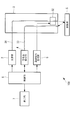
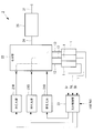
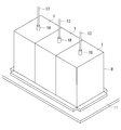
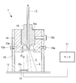
- FIG. 1 is an overall configuration diagram of an optical scanning endoscope apparatus according to a first embodiment of the present invention. It is a block diagram of the light source part of the optical scanning endoscope apparatus of FIG. It is a perspective view which shows the external appearance of the light quantity detection apparatus which concerns on the 1st Embodiment of this invention. It is a longitudinal cross-sectional view which shows the structure of the light quantity detection apparatus which concerns on the 1st Embodiment of this invention. It is a figure explaining operation
- FIG. 1 An optical scanning endoscope apparatus 100 according to a first embodiment of the present invention and a light amount detection apparatus 1 mounted thereon will be described with reference to FIGS. 1 to 5C.
- the optical scanning endoscope apparatus 100 according to the present embodiment irradiates the subject S while scanning the illumination light while irradiating the subject S while scanning the illumination light.
- An optical scanning endoscope 3 for receiving the signal light, a signal light detection unit 4 for detecting the signal light received by the optical scanning endoscope 3, and a drive signal for scanning the illumination light.
- a drive signal generation unit 5, a light source unit 2, a signal light detection unit 4, a control unit 6 that controls the drive signal generation unit 5, and a display unit 7 that displays a two-dimensional image are provided.
- the light source unit 2 includes three light sources 21R, 21G, and 21B that respectively generate red, green, and blue laser beams, and lasers that are output from the three light sources 21R, 21G, and 21B.
- a multiplexing unit 22 for multiplexing light.
- the three light sources 21R, 21G, and 21B are controlled by the control unit 6 so as to sequentially generate laser beams.
- the multiplexing unit 22 is connected to the illumination optical fiber 31 in the optical scanning endoscope 3 via the multiplexing optical fiber 24 and the fiber connecting unit 25, and the red, green, and blue laser lights are sequentially illuminated. Light is supplied from the multiplexing unit 22 to the illumination optical fiber 31 through the multiplexing optical fiber 24 and the fiber connecting unit 25.
- the three light sources 21R, 21G, and 21B may be controlled by the control unit 6 so as to simultaneously generate laser beams.
- white light is generated from the red, green, and blue laser beams in the multiplexing unit 22, and the white light is supplied to the illumination optical fiber 31 as illumination light.
- the light source unit 2 is detected by the light amount detection device 1 that detects the light amount of a part of the light branched as the monitor light from the laser light output from each of the light sources 21R, 21G, and 21B, and the light amount detection device 1. And a light source control unit 23 that controls the light sources 21R, 21G, and 21B based on the amount of light.
- Three light quantity detection devices 1 are provided corresponding to the respective light sources 21R, 21G, and 21B. Each light quantity detection device 1 detects the light quantity of the monitor light of the laser light output from the corresponding light source 21R, 21G or 21B, and outputs a detection signal Sr, Sg or Sb based on the detected light quantity to the light source control unit 23. To do. The detailed configuration of the light quantity detection device 1 will be described in detail.
- the light source control unit 23 outputs an adjustment signal for adjusting the amount of laser light to the corresponding light sources 21R, 21G, and 21B according to the detection signals Sr, Sg, and Sb under the control of the control unit 6. In response to the adjustment signal, the light sources 21R, 21G, and 21B change the output light amount.
- the optical scanning endoscope 3 includes an illumination optical fiber 31, a scanning unit 32 that is provided near the distal end of the illumination optical fiber 31 and vibrates the distal end of the illumination optical fiber 31, and signal light from the subject S. And a light receiving optical fiber 33 for receiving light.
- the illumination optical fiber 31 guides the illumination light incident on the proximal end from the multiplexing unit 22 of the light source unit 2, and is directed toward the subject S from the distal end disposed at the distal end portion of the optical scanning endoscope 3.
- the scanning unit 32 is arranged in the vicinity of a piezoelectric actuator having a piezoelectric element fixed near the tip of the illumination optical fiber 31 or a permanent magnet fixed near the tip of the illumination optical fiber 31 and the permanent magnet.
- An electromagnetic actuator having a coil is provided. The actuator is driven by a drive signal from the drive signal generator 5 to vibrate the tip of the illumination optical fiber 31 in the radial direction. Thereby, the illumination light emitted from the tip of the illumination optical fiber 31 is scanned.
- the signal light (for example, the reflected light of the illumination light or the fluorescence excited by the illumination light) generated in the subject S by the illumination light is incident on the distal end surface of the light receiving optical fiber 33, and the light receiving optical fiber. 33 is guided to the signal light detection unit 4.
- the signal light detection unit 4 includes a light detector such as a photodiode (PD), and converts the signal light incident from the light receiving optical fiber 33 into an electric signal having a level corresponding to the intensity of the signal light. Output to unit 6.
- the control unit 6 generates an image of the subject S by associating the level of the electrical signal received from the signal light detection unit 4 with the irradiation position of the illumination light. The generated image is displayed on a display unit 7 connected to the control unit 6.
- FIG. 3 shows the appearance of the three light quantity detection devices 1.
- the light amount detection device 1 is connected to a horizontally arranged substrate 11, a light receiving element (light receiving unit) 12 mounted on the substrate 11, and a multiplexing unit 22 to guide monitor light.
- An optical fiber 13 for detecting the color of light to be detected a holder (adjusting unit) 14 for holding the optical fiber 13 for detecting the light quantity, and an optical for selecting the monitor light of the color to be detected from the monitor light emitted from the optical fiber 13 for detecting the light quantity.
- a filter 15, a frame 16 for fixing the holder 14 to the substrate 11 and shielding the periphery of the light receiving element 12, and a monitor (display unit) 17 for displaying the amount of received light detected by the light receiving element 12 are provided. . Almost the entire light amount detection device 1 is covered with a light-shielding box-shaped cover 8 (see FIG. 3).
- the substrate 11 is a printed circuit board on which a circuit for processing an electrical signal output from the light receiving element 12 is formed, and is electrically connected to the monitor 17.
- the light receiving element 12 is a PD or an avalanche photodiode (APD), for example, and has a light receiving surface 12a that is arranged facing upward and receives monitor light.
- the light receiving element 12 generates an electric signal corresponding to the amount of received light by photoelectrically converting the monitor light received by the light receiving surface 12a.
- the electrical signal is processed by the circuit of the substrate 11 and is generated into the detection signal Sr, Sg or Sb.
- the detection signal Sr, Sg, or Sb is transmitted to the light source control unit 23 as described above, and the value of the amount of received light indicated by the detection signal Sr, Sg, or Sb is displayed on the monitor 17.
- the monitor 17 may be the same display device as the display unit 7 or may be a separate display device from the display unit 7.
- the optical fiber 13 for detecting the light amount is covered with a light-shielding outer sheath so that monitor light does not leak outside from the portions other than the incident end face and the exit end face 13a at both ends.
- the incident end face of the light quantity detecting optical fiber 13 is connected to the combining section 22, and the monitor light branched from the laser light in the combining section 22 is configured to enter the incident end face of the light quantity detecting optical fiber 13. Yes.
- a part of the laser light after being multiplexed in the multiplexing unit 22 is branched by a beam splitter or the like, and the branched laser light is further divided into three parts. It is configured to be incident on the incident end face.
- a part of each laser beam before multiplexing is configured to be branched between the light sources 21R, 21G, 21B and the multiplexing unit 22 or within the multiplexing unit 22 and enter the incident end face. It may be.
- the filter 15 may not be provided.
- the emission end face 13a of the light quantity detection optical fiber 13 is inclined with respect to the optical axis A of the light quantity detection optical fiber 13, and the monitor light L diverges in an oblique direction with respect to the optical axis A from the emission end face 13a. It is emitted as a light beam.
- the distal end portion of the light quantity detection optical fiber 13 is covered with a cylindrical ferrule 18 disposed coaxially with the optical axis A.
- the holder 14 has a cylindrical fitting hole 14a into which the ferrule 18 is fitted in the longitudinal direction.
- the ferrule 18 is fitted in the fitting hole 14a so as to be continuously and smoothly rotatable around the longitudinal axis, whereby the light quantity detecting optical fiber 13 is continuously and smoothly rotated around the optical axis A. It is held by the holder 14 as possible.
- the frame 16 is a cylindrical light-shielding member that stands upright on the substrate 11 and is fixed to the substrate 11.
- the periphery of the light receiving element 12 is covered by the frame 16 so that light other than the monitor light L to be detected does not enter the light receiving surface 12a from the surroundings.
- the holder 14 is fixed to the upper part in the frame 16 by a fixing screw 16a.
- the holder 14 is configured so that the optical axis A of the light quantity detecting optical fiber 13 and the optical axis B of the light receiving surface 12a are substantially parallel to each other and decentered from each other, and the emission end surface 13a and the light receiving surface 12a are optical axes A.
- the optical axis B of the light receiving surface 12a is an axis that passes through the center of the light receiving surface 12a and is perpendicular to the light receiving surface 12a.
- the base end portion of the ferrule 18 passes through the ceiling of the cover 8 and protrudes to the outside of the cover 8.
- the operator can rotate the light amount detection optical fiber 13 in the cover 8 around the optical axis A by gripping and manually operating the proximal end portion of the ferrule 18. Further, the ferrule 18 and the light quantity detection optical fiber 13 are moved with respect to the holder 14 and the frame 16 at an arbitrary rotation angle by a fixing screw 16b inserted through the holder 14 from the outside of the frame 16 to the outer peripheral surface of the ferrule 18. It can be fixed.
- the monitor light L is emitted in an oblique direction with respect to the optical axis A from the emission end face 13 a inclined with respect to the optical axis A. Therefore, as shown in FIG. 5A to FIG. 5C, the monitor light L emitted from the emission end face 13a is rotated about the optical axis A due to the rotation of the optical fiber 13 for detecting the light amount about the optical axis A. A spot of the monitor light L rotates around the optical axis A on the substrate 11.
- the optical axis C of the monitor light L is arranged farthest from the optical axis B of the light receiving surface 12a (see FIG. 5A), the area where the spot overlaps the light receiving surface 12a becomes substantially zero, and the monitor light L Is positioned closest to the optical axis B of the light receiving surface 12a (see FIG. 5C), the distance between the optical axes A and B so that the spot overlaps the entire range of the light receiving surface 12a.
- the inclination angle of the injection end face 13a is designed. 5A to 5C, the upper part shows a longitudinal sectional view of the light quantity detection device 1, and the lower part shows a plan view of the substrate 11 and the light receiving surface 12a as viewed from above.
- a part of the laser light output from the light source 21R, 21G or 21B corresponds to the light quantity detection optical fiber 13 corresponding to the monitor light L. And is emitted from the emission end surface 13a toward the light receiving surface 12a in the frame 16.
- the light receiving amount of the monitor light L on the light receiving surface 12 a is detected by the light receiving element 12, and the detected light receiving amount is displayed on the monitor 17.
- the ratio of the output light amount of the laser light from the light source 21R, 21G, or 21B and the light amount of the monitor light L branched to the light amount detection optical fiber 13 is constant. Therefore, based on the received light amount displayed on the monitor 17, the operator can monitor the output light amount of the light source 21R, 21G, or 21B. Further, a detection signal Sr, Sg, or Sb based on the amount of received light of the monitor light L is transmitted from the light receiving element 12 to the light source control unit 23, and detection is performed so that the amount of illumination light applied to the subject S falls within an appropriate range. The output light amount of the light source 21R, 21G, or 21B is adjusted based on the signal Sr, Sg, or Sb.
- the operator loosens the fixing screw 16b, and then receives the received light displayed on the monitor 17.
- the amount of monitor light L received by the light receiving element 12 can be adjusted to an appropriate amount by rotating the base end portion of the ferrule 18 protruding outside the cover 8 while checking the amount. That is, the operator rotates the light amount detection optical fiber 13 by rotating the base end portion of the ferrule 18, thereby reducing or increasing the amount of overlap of the monitor light L emitted from the emission end surface 13 a with the light receiving surface 12 a. Can be made.
- the optical axis C of the monitor light L is decentered with respect to the optical axis B of the light receiving surface 12a around the optical axis A by the rotation of the light amount detection optical fiber 13 around the optical axis A.
- the distance between the optical axis C of the monitor light L and the optical axis B of the light receiving surface 12a changes in a direction intersecting the optical axes B and C.
- the adjustment range of the amount of received light of the monitor light L on the light receiving surface 12a is larger. Expanding. In particular, the lower limit of the received light amount adjustment range is expanded to substantially zero.
- the ferrule 18 and the light quantity detection optical fiber 13 can be continuously and smoothly rotated, the distance between the optical axis C of the monitor light L and the optical axis B of the light receiving surface 12a also changes continuously, and the light receiving element.
- the amount of received light 12 also changes continuously. As a result, fine adjustment of the amount of received light is facilitated. For example, even when the appropriate range of the amount of received light of the light receiving element 12 is narrow, there is an advantage that the amount of received light of the monitor light L can be adjusted appropriately.
- an optical scanning endoscope apparatus according to a second embodiment of the present invention and a light amount detection apparatus 10 mounted thereon will be described with reference to FIGS. 6A to 7.
- a configuration different from that of the first embodiment will be described, and a configuration common to the first embodiment will be denoted by the same reference numeral and description thereof will be omitted.
- the optical scanning endoscope apparatus according to the present embodiment is the same as that of the first embodiment except that the light quantity detection apparatus 10 is provided instead of the light quantity detection apparatus 1.
- the light quantity detection device 10 intersects the optical axis B with the substrate 11, the light receiving element 12, the light quantity detection optical fiber 131, and the emission end face 131a of the light quantity detection optical fiber 131.
- a swing jig (adjustment unit) 141 for swinging around the swing axis D, an optical filter 15, a frame 16, and a monitor 17 are provided. In FIGS. 6A to 7, the monitor 17 is not shown.
- the light quantity detection optical fiber 131 is configured in the same manner as the light quantity detection optical fiber 13 of the first embodiment except that it has an emission end face 131a perpendicular to the optical axis A. From the emission end face 131a, the monitor light L is emitted as a divergent light beam along an optical axis C coaxial with the optical axis A of the light quantity detecting optical fiber 131.
- the swing jig 141 has a cylindrical fitting hole 141a into which the ferrule 18 is fitted in the longitudinal direction.
- the ferrule 18 is fixed in the fitting hole 141 a, whereby the light amount detection optical fiber 131 is fixed to the swing jig 141.
- the swing jig 141 holds the light amount detecting optical fiber 131 so that the emission end face 131a and the light receiving face 12a are substantially opposed to each other with a gap in the direction along the optical axes A and B.
- Reference numeral 141 c is a screw for fixing the ferrule 18 to the swing jig 141.
- the swing jig 141 is supported by the frame 16 so as to be able to swing continuously and smoothly around the swing axis D orthogonal to the optical axis B.
- Reference numeral 141b is a pin that is arranged along the swing axis D and connects the swing jig 141 to the frame 16 so as to be swingable.
- the exit end surface 131a is positioned on the swing axis D so that the exit end surface 131a is the center of swing, and is positioned on the optical axis B of the light receiving surface 12a.
- the emission end surface 131a is oscillated at the same position by the oscillation of the oscillation jig 141, and the monitor light emitted from the emission end surface 131a is within the plane including the optical axis B as shown in FIG. Swing.
- the spot of the monitor light L linearly moves in a direction substantially orthogonal to the optical axis B of the light receiving surface 12 a, thereby changing the area where the spot overlaps with the light receiving surface 12 a.
- the amount of received light changes.
- the base end portion of the ferrule 18 passes through the ceiling of the cover 8 and protrudes to the outside of the cover 8.
- the operator can swing the swing jig 141 and the light amount detection optical fiber 131 in the cover 8 about the swing axis D by gripping and manually operating the proximal end portion of the ferrule 18.
- the frame 16 is formed with an arc-shaped slit, and the rocking jig 141 and the light amount detection light are fixed by a fixing screw 16c inserted into the rocking jig 141 from the outside of the frame 16 through the slit.
- the fiber 131 can be fixed to the frame 16 at an arbitrary swing angle.
- the operation of the light quantity detection device 10 configured as described above will be described.
- the light amount detection device 10 when the received light amount displayed on the monitor 17 is larger or smaller than the appropriate range of the received light amount of the light receiving element 12, the operator loosens the fixing screw 16c, The light receiving amount of the monitor light L by the light receiving element 12 is adjusted to an appropriate amount by swinging the base end portion of the ferrule 18 that protrudes outside the cover 8 while checking the light receiving amount displayed on the monitor 17. Can do. That is, the operator swings the light amount detecting optical fiber 131 by swinging the base end portion of the ferrule 18, thereby reducing the amount of overlap of the monitor light L emitted from the exit end surface 131 a with the light receiving surface 12 a. Or it can be increased.
- the optical axis C of the monitor light L is within the plane including the optical axis B of the light receiving surface 12a due to the oscillation of the emission end surface 131a around the oscillation axis D intersecting the optical axis B.
- the distance between the optical axis C of the monitor light L and the optical axis B of the light receiving surface 12a changes in a direction intersecting the optical axes B and C.
- the adjustment range of the light reception amount of the monitor light L on the light receiving surface 12a can be expanded, and in particular, the lower limit of the light reception amount adjustment range can be expanded to substantially zero.
- the emission end face 131a can be continuously and smoothly oscillated, the distance between the optical axis C of the monitor light L and the optical axis B of the light receiving face 12a also changes continuously, and the amount of light received by the light receiving element 12 is also increased. It changes continuously. Thereby, fine adjustment of the amount of received light can be easily performed.
- FIGS. 8A to 10 An optical scanning endoscope apparatus according to a third embodiment of the present invention and a light amount detection apparatus 20 mounted thereon will be described with reference to FIGS. 8A to 10.
- the optical scanning endoscope apparatus according to the present embodiment is the same as that of the first embodiment except that a light quantity detection device 20 is provided instead of the light quantity detection apparatus 1.
- the light quantity detection device 20 is parallel to the direction in which the substrate 11, the light receiving element 12, the light quantity detection optical fiber 131, and the light quantity detection optical fiber 131 intersect the optical axis B.
- a shift jig (adjustment unit) 142 for moving, an optical filter 15, a frame 16 for fixing the shift jig 142 to the substrate 11, and a monitor 17 are provided. 8A to 10, the monitor 17 is not shown.
- the shift jig 142 has a cylindrical fitting hole 142a into which the ferrule 18 is fitted in the longitudinal direction.
- the ferrule 18 is fixed in the fitting hole 142a, whereby the light quantity detecting optical fiber 131 is fixed to the shift jig 142.
- Reference numeral 142 b is a screw for fixing the ferrule 18 to the shift jig 142.
- the shift jig 142 holds the light quantity detecting optical fiber 131 so that the emission end face 131a and the light receiving face 12a are substantially opposed to each other with a gap in the direction along the optical axis A.
- the shift jig 142 is supported by the frame 16 so as to be continuously and smoothly translatable in a direction intersecting the optical axis B.
- the monitor light L emitted from the emission end face 131a is translated in the direction intersecting the optical axis B as shown in FIG.
- the area where the spot of the monitor light L overlaps the light receiving surface 12a is changed by linearly moving the spot of the monitor light L in the direction intersecting the optical axis B of the light receiving surface 12a. The amount changes.
- the optical axis C of the monitor light L when the optical axis C of the monitor light L is arranged farthest from the optical axis B of the light receiving surface 12a, the area where the spot overlaps with the light receiving surface 12a becomes substantially zero, and the monitor When the optical axis C of the light L is disposed closest to the optical axis B of the light receiving surface 12a, the distance between the optical axes A and B or the optical axes A, B so that the spot overlaps the entire range of the light receiving surface 12a.
- the relative position of B is designed.
- the base end portion of the ferrule 18 passes through the ceiling of the cover 8 and protrudes to the outside of the cover 8.
- the operator can move the shift jig 142 and the light amount detection optical fiber 131 in the cover 8 in parallel to the direction intersecting the optical axis B by gripping and manually operating the base end of the ferrule 18. it can.
- the frame 16 is formed with a slit extending in a direction intersecting the optical axis B, and the fixing jig 16d inserted into the shift jig 142 from the outside of the frame 16 through the slit,
- the light quantity detecting optical fiber 131 can be fixed to the frame 16 at an arbitrary position.
- the operation of the light quantity detection device 20 configured as described above will be described.
- the operator loosens the fixing screw 16d
- the amount of received light of the monitor light L by the light receiving element 12 is adjusted to an appropriate amount by moving the base end portion of the ferrule 18 projecting outside the cover 8 while confirming the amount of received light displayed on the monitor 17.
- the operator translates the light amount detecting optical fiber 131 by translating the base end portion of the ferrule 18, thereby reducing the overlap amount of the monitor light L emitted from the emission end surface 131 a with the light receiving surface 12 a. Or it can be increased.
- the optical axis C of the monitor light L is translated in the direction intersecting the optical axis B by the parallel movement of the light amount detection optical fiber 131 in the direction intersecting the optical axis B.
- the distance between the optical axis C of the monitor light L and the optical axis B of the light receiving surface 12a changes in a direction intersecting the optical axes B and C.
- the exit end face 131a can be continuously and smoothly translated, the distance between the optical axis C of the monitor light L and the optical axis B of the light receiving surface 12a also changes continuously, and the amount of light received by the light receiving element 12 also increases. It changes continuously. Thereby, fine adjustment of the amount of received light can be easily performed.
- the shift jig 142 is translated in the direction intersecting the optical axis B.
- the optical axis A of the light quantity detecting optical fiber 131 is used.
- the shift jig 142 may be rotated around the rotation axis E that is eccentric with respect to both the optical axis B of the light receiving surface 12a.
- the rotation axis E preferably coincides with the center axis of the frame 16.
- the rotation of the shift jig 142 causes the optical axis C of the monitor light L to rotate about the rotational axis E eccentric with respect to the optical axis B of the light receiving surface 12a, as in the first embodiment. Therefore, even in this case, the same effect as when the shift jig 142 is moved in parallel can be obtained.
- FIGS. 11A and 11B an optical scanning endoscope apparatus according to a fourth embodiment of the present invention and a light amount detection apparatus 30 mounted thereon will be described with reference to FIGS. 11A and 11B.
- configurations different from those in the first to third embodiments will be described, and configurations common to the first to third embodiments are denoted by the same reference numerals and description thereof will be omitted.
- the optical scanning endoscope apparatus according to the present embodiment is the same as that of the first embodiment except that a light amount detection device 30 is provided instead of the light amount detection device 1.
- the light amount detection device 30 includes a substrate 11, a light receiving element 12, a light amount detection optical fiber 131, a holder 143 that holds the light amount detection optical fiber 131, and an optical filter 15. And a frame 16 for fixing the holder 143 to the substrate 11, a monitor 17, and a Risner prism (adjustment unit) 19 disposed between the emission end face 131a and the light receiving face 12a.
- the monitor 17 is not shown.
- the holder 143 has a cylindrical fitting hole 143a into which the ferrule 18 is fitted in the longitudinal direction.
- the ferrule 18 is fixed in the fitting hole 143 a, whereby the light quantity detection optical fiber 131 is fixed to the holder 143.
- the holder 143 is configured so that the emission end surface 131a and the light receiving surface 12a face each other with a space in the direction along the optical axis A, and the optical axis A of the light quantity detecting optical fiber 131 and the optical axis B of the light receiving surface 12a.
- the optical fibers 131 for detecting the amount of light are held so that they are decentered from each other.
- Reference numeral 143 b is a screw for fixing the ferrule 18 to the holder 143.
- the Risner prism 19 is a wedge-shaped prism having an incident surface 19a that is disposed on the exit end surface 131a side and perpendicular to the optical axis A, and a deflecting surface 19b that is disposed on the light receiving surface 12a side and is inclined with respect to the optical axis A. It is.
- the monitor light L incident on the incident surface 19a along the optical axis A is deflected in a direction inclined to the optical axis A and emitted from the deflecting surface 19b.
- the peripheral edge of the Risner prism 19 is held by an annular rotating plate (adjusting unit) 144.
- the rotating plate 144 is supported by the frame 16 so as to be continuously and smoothly rotatable about a rotation axis F substantially parallel to the optical axis A.
- the rotation axis F coincides with the optical axis A, but the rotation axis F may be eccentric with respect to the optical axis A.
- a part of the rotating plate 144 in the circumferential direction protrudes outside the cover 8 through the side wall of the cover 8. The operator can manually rotate the peripheral edge of the rotating plate 144 to rotate the rotating plate 144 and the Risner prism 19 in the cover 8 around the rotation axis F.
- a slit extending in the circumferential direction is formed in the frame 16, and the rotating plate 144 and the Risner prism 19 are arbitrarily rotated by a fixing screw 16e inserted into the rotating plate 144 from the outside of the frame 16 through the slit. It can be fixed with respect to the frame 16 at an angle.
- the monitor light L emitted from the deflecting surface 19b is rotated around the optical axis A by the rotation of the Risner prism 19 around the rotation axis F, whereby the spot of the monitor light L on the substrate 11 is rotated around the optical axis A.
- Rotate Since the optical axis A is decentered with respect to the optical axis B of the light receiving surface 12a, the area where the spot overlaps with the light receiving surface 12a changes due to the rotational movement of the spot, and the amount of monitor light L received on the light receiving surface 12a changes.
- the optical axis C of the monitor light L is disposed farthest from the optical axis B of the light receiving surface 12a (see FIG. 11B), the area where the spot overlaps the light receiving surface 12a becomes substantially zero, and the monitor light L Is positioned closest to the optical axis B of the light receiving surface 12a (see FIG. 11A), the distance between the optical axes A and B, so that the spot overlaps the entire range of the light receiving surface 12a.
- the inclination angle of the deflecting surface 19b of the Risner prism 19 is designed.
- the operation of the light quantity detection device 30 configured as described above will be described.
- the light amount detection device 30 when the received light amount displayed on the monitor 17 is larger or smaller than the appropriate range of the received light amount of the light receiving element 12, the operator loosens the fixing screw 16e, The amount of monitor light L received by the light receiving element 12 can be adjusted to an appropriate amount by rotating the periphery of the rotating plate 144 protruding outside the cover 8 while checking the amount of received light displayed on the monitor 17. That is, the operator rotates the Risner prism 19 by the rotation of the rotating plate 144, thereby reducing or increasing the amount of overlap of the monitor light L emitted from the deflection surface 19b of the Risner prism 19 with the light receiving surface 12a. Can be made.
- the optical axis C of the monitor light L is rotated around the optical axis A in which the optical axis C of the monitor light L is decentered with respect to the optical axis B of the light receiving surface 12a by rotating around the rotational axis F of the Risner prism 19.
- the distance between the optical axis C of the monitor light L and the optical axis B of the light receiving surface 12a changes in a direction intersecting the optical axes B and C.
- the adjustment range of the light reception amount of the monitor light L on the light receiving surface 12a can be expanded, and in particular, the lower limit of the light reception amount adjustment range can be expanded to substantially zero.
- the Risner prism 19 can be continuously and smoothly rotated, the distance between the optical axis C of the monitor light L and the optical axis B of the light receiving surface 12a also changes continuously, and the amount of light received by the light receiving element 12 also increases. It changes continuously. Thereby, fine adjustment of the amount of received light can be easily performed.
- the operator manually adjusts the amount of light received by the light receiving element 12 while monitoring the amount of received light displayed on the monitor 17.
- the amount may be configured to be automatically adjusted within an appropriate range.
- the light quantity detection devices 1, 10, 20, and 30 include a motor for rotating, swinging, translating the light quantity detection optical fibers 13 and 131, or rotating the Risner prism 19, and a light receiving device.
- a control device that controls the motor based on the detection signal Sr, Sg, or Sb from the element 12 is provided. The control device drives the motor so that the amount of received light indicated by the detection signal Sr, Sg, or Sb becomes a preset appropriate value.
- Light quantity detection device 12 Light receiving element (light receiving part) 12a Light receiving surface 13 Optical fiber for detecting light quantity (optical fiber) 14 Holder (Adjustment part) 141 Swing jig (adjustment part) 142 Shift jig (adjustment part) 144 Rotating plate (adjustment part) 17 Monitor (display unit) 19 Risner prism (adjustment unit)
Landscapes
- Physics & Mathematics (AREA)
- Health & Medical Sciences (AREA)
- Life Sciences & Earth Sciences (AREA)
- Optics & Photonics (AREA)
- Surgery (AREA)
- Biomedical Technology (AREA)
- Medical Informatics (AREA)
- Radiology & Medical Imaging (AREA)
- Nuclear Medicine, Radiotherapy & Molecular Imaging (AREA)
- Engineering & Computer Science (AREA)
- Biophysics (AREA)
- Heart & Thoracic Surgery (AREA)
- Pathology (AREA)
- Molecular Biology (AREA)
- Animal Behavior & Ethology (AREA)
- General Health & Medical Sciences (AREA)
- Public Health (AREA)
- Veterinary Medicine (AREA)
- General Physics & Mathematics (AREA)
- Astronomy & Astrophysics (AREA)
- Instruments For Viewing The Inside Of Hollow Bodies (AREA)
Abstract
光量検知装置(1)は、光源から出力された光の一部(L)を導光して射出端面(13a)から射出する光ファイバ(13)と、射出端面(13a)と略対向して配置された受光面(12a)を有し、受光面(12a)における光(L)の受光量を検出する受光部(12)と、射出端面(13a)から射出された光(L)の光軸(C)と受光面(12a)の光軸(B)との距離を変更することで、受光面(12a)におけるモニタ光(L)の受光量を調整する調整部(14)とを備える。
Description
本発明は、光源から出力される光の光量を検知する光量検知装置に関する。
従来、内視鏡などの観察装置の光源装置には、生体に照射される光の光量をモニタリングするために、光源から出力される光の光量を検知する光量検知装置が設けられている(例えば、特許文献1参照。)。特許文献1では、光源から出力された光の一部をモニタリング用に分岐し、分岐された一部の光の光量を光検出器によって検出している。
フォトダイオード(PD)のような光電変換素子を備える光検出器は、受光量を正確に検出することができる適正範囲を有し、受光量が適正範囲を超える、または下回るときには受光量の検出精度が低下する。したがって、光源の出力光量を正確に検知するためには、光検出器による光の受光量が適正範囲内に収まるように、光検出器による光の受光量を調整する必要がある。特許文献1では、一部の光を導光する光ファイバとPDとの距離を光軸に沿う方向に変更することで、PDによる光の受光量を調整している。
光ファイバと光検出器との間に確保することができる距離は光源装置のサイズによって制限されるため、光ファイバと光検出器との距離の変更による受光量の調整範囲には限界がある。光源から出力された光からの一部の光の分岐比には光源装置毎の個体差が生じるため、光量検知装置に導光される光の光量にはばらつきが生じる。このような光源装置の個体差に関わらず光検出器による光の受光量を適正範囲内に調整することができるように、受光量のより広い調整範囲が望まれる。
本発明は、上述した事情に鑑みてなされたものであって、モニタリング用の光の受光量の調整範囲を拡大して、光源装置の個体差に関わらず光源の出力光量を正確にモニタリングすることができる光量検知装置を提供することを目的とする。
上記目的を達成するため、本発明は以下の手段を提供する。
本発明の一態様は、光源から出力された光の一部を導光して射出端面から射出する光ファイバと、該光ファイバの前記射出端面と略対向して配置された受光面を有し、該受光面で受光された前記一部の光の受光量を検出する受光部と、前記受光面で受光される前記一部の光の受光量を調整する調整部とを備え、該調整部が、前記射出端面から射出された前記一部の光の光軸と、前記受光面の中心を通り前記受光面に垂直な前記受光面の光軸との距離を変更する光量検知装置である。
本発明の一態様は、光源から出力された光の一部を導光して射出端面から射出する光ファイバと、該光ファイバの前記射出端面と略対向して配置された受光面を有し、該受光面で受光された前記一部の光の受光量を検出する受光部と、前記受光面で受光される前記一部の光の受光量を調整する調整部とを備え、該調整部が、前記射出端面から射出された前記一部の光の光軸と、前記受光面の中心を通り前記受光面に垂直な前記受光面の光軸との距離を変更する光量検知装置である。
本態様によれば、光源から出力された光の一部が光ファイバによって導光され、光ファイバの射出端面から射出された光が受光面で受光されることで、前記一部の光の光量が検出される。したがって、受光部によって検出された光量に基づいて光源の出力光量をモニタリングすることができる。
この場合に、調整部によって、受光面の光軸と光ファイバの射出端面からの光の光軸との間の距離を変更して受光面と射出端面からの光との相対位置を光軸に交差する方向に変更することで、受光面での光の受光量が変化する。このように、受光面の光軸と射出端面からの光の光軸との距離を変更することで、光ファイバの射出端面と受光面との間の光軸方向の距離を変更する場合と比べて、光および受光面の少ない相対移動量で、受光面での光の受光量をより広い範囲内で調整することができる。これにより、光源装置の個体差に関わらず受光部による光の受光量を適正範囲内に調整することができ、光源の出力光量を正確にモニタリングすることができる。
上記態様においては、前記受光部によって検出された前記受光量を表示する表示部を備えていてもよい。
このようにすることで、操作者が表示部に表示された受光量を確認しながら、調整部を作動させることで受光量の調整を行うことができる。
このようにすることで、操作者が表示部に表示された受光量を確認しながら、調整部を作動させることで受光量の調整を行うことができる。
上記態様においては、前記調整部が、前記距離を連続的に変更することで前記受光量を連続的に調整可能であってもよい。
このようにすることで、受光部による光の受光量を高精度に調整することができる。
このようにすることで、受光部による光の受光量を高精度に調整することができる。
上記態様においては、前記光ファイバの前記射出端面が、該光ファイバの光軸に対して傾斜し、前記光ファイバの光軸および前記受光面の光軸が、相互に偏心し、前記調整部が、前記光ファイバを該光ファイバの光軸回りに回転させてもよい。
光ファイバの光軸に対して傾斜した射出端面からは、光ファイバの光軸に対して斜め方向に光が射出される。したがって、光ファイバの回転によって、射出端面からの光の光軸は受光面の光軸に対して偏心した軸回りに回転移動する。このような射出端面からの光の光軸の回転移動によって、受光面の光軸と射出端面からの光の光軸との距離を変更することができる。
光ファイバの光軸に対して傾斜した射出端面からは、光ファイバの光軸に対して斜め方向に光が射出される。したがって、光ファイバの回転によって、射出端面からの光の光軸は受光面の光軸に対して偏心した軸回りに回転移動する。このような射出端面からの光の光軸の回転移動によって、受光面の光軸と射出端面からの光の光軸との距離を変更することができる。
上記態様においては、前記調整部が、前記射出端面を前記受光面の光軸に交差する方向の揺動軸回りに揺動させてもよい。
このように、射出端面の揺動によって当該射出端面から射出される光を揺動させることで、受光面の光軸と射出端面からの光の光軸との距離を変更することができる。
このように、射出端面の揺動によって当該射出端面から射出される光を揺動させることで、受光面の光軸と射出端面からの光の光軸との距離を変更することができる。
上記態様においては、前記調整部が、前記光ファイバを前記受光面の光軸に交差する方向に平行移動させてもよい。
このように光ファイバを平行移動させることで、射出端面からの光の光軸と受光面の光軸との距離を一方向に変化させることができる。
このように光ファイバを平行移動させることで、射出端面からの光の光軸と受光面の光軸との距離を一方向に変化させることができる。
上記態様においては、前記調整部が、前記受光面の光軸および前記光ファイバの光軸に対して偏心した回転軸回りに前記光ファイバを回転移動させてもよい。
このようにすることで、光ファイバの回転移動によって、射出端面からの光の光軸は受光面の光軸に対して偏心した軸回りに回転移動する。このような射出端面からの光の光軸の回転移動によって、受光面の光軸と射出端面からの光の光軸との距離を変更することができる。
このようにすることで、光ファイバの回転移動によって、射出端面からの光の光軸は受光面の光軸に対して偏心した軸回りに回転移動する。このような射出端面からの光の光軸の回転移動によって、受光面の光軸と射出端面からの光の光軸との距離を変更することができる。
上記態様においては、前記光ファイバの前記射出端面と前記受光面との間に配置され、前記射出端面から入射した前記一部の光を偏向するリズナープリズムを備え、前記光ファイバの光軸および前記受光面の光軸が、相互に偏心し、前記調整部が、前記リズナープリズムを前記光ファイバの光軸に平行な回転軸回りに回転させてもよい。
このようにすることで、リズナープリズムからは、光ファイバの光軸に対して斜め方向に光が射出される。したがって、リズナープリズムの回転によって、射出端面からの光の光軸は受光面の光軸に対して偏心した軸回りに回転移動する。このような射出端面からの光の光軸の回転移動によって、受光面の光軸と射出端面からの光の光軸との距離を変更することができる。
このようにすることで、リズナープリズムからは、光ファイバの光軸に対して斜め方向に光が射出される。したがって、リズナープリズムの回転によって、射出端面からの光の光軸は受光面の光軸に対して偏心した軸回りに回転移動する。このような射出端面からの光の光軸の回転移動によって、受光面の光軸と射出端面からの光の光軸との距離を変更することができる。
本発明によれば、モニタリング用の光の受光量の調整範囲を拡大して、光源装置の個体差に関わらず光源の出力光量を正確にモニタリングすることができるという効果を奏する。
(第1の実施形態)
本発明の第1の実施形態に係る光走査型内視鏡装置100およびこれに搭載された光量検知装置1について図1から図5Cを参照して説明する。
本実施形態に係る光走査型内視鏡装置100は、図1に示されるように、照明光を発生する光源部2と、照明光を走査しながら被検体Sに照射するとともに被検体Sからの信号光を受光する光走査型内視鏡3と、光走査型内視鏡3によって受光された信号光を検出する信号光検出部4と、照明光を走査するための駆動信号を生成する駆動信号生成部5と、光源部2、信号光検出部4および駆動信号生成部5を制御する制御部6と、2次元画像を表示する表示部7とを備えている。
本発明の第1の実施形態に係る光走査型内視鏡装置100およびこれに搭載された光量検知装置1について図1から図5Cを参照して説明する。
本実施形態に係る光走査型内視鏡装置100は、図1に示されるように、照明光を発生する光源部2と、照明光を走査しながら被検体Sに照射するとともに被検体Sからの信号光を受光する光走査型内視鏡3と、光走査型内視鏡3によって受光された信号光を検出する信号光検出部4と、照明光を走査するための駆動信号を生成する駆動信号生成部5と、光源部2、信号光検出部4および駆動信号生成部5を制御する制御部6と、2次元画像を表示する表示部7とを備えている。
光源部2は、図2に示されるように、赤、緑および青のレーザ光をそれぞれ発生する3個の光源21R,21G,21Bと、3個の光源21R,21G,21Bから出力されたレーザ光を合波する合波部22とを備えている。
3個の光源21R,21G,21Bは、レーザ光を順番に発生するように制御部6によって制御される。合波部22は、合波用光ファイバ24およびファイバ接続部25を介して光走査型内視鏡3内の照明用光ファイバ31と接続され、赤、緑および青のレーザ光が順番に照明光として合波部22から合波用光ファイバ24およびファイバ接続部25を介して照明用光ファイバ31に供給されるようになっている。
3個の光源21R,21G,21Bは、レーザ光を同時に発生するように制御部6によって制御されてもよい。この場合、合波部22内で赤、緑および青のレーザ光から白色光が生成され、白色光が照明光として照明用光ファイバ31に供給される。
3個の光源21R,21G,21Bは、レーザ光を順番に発生するように制御部6によって制御される。合波部22は、合波用光ファイバ24およびファイバ接続部25を介して光走査型内視鏡3内の照明用光ファイバ31と接続され、赤、緑および青のレーザ光が順番に照明光として合波部22から合波用光ファイバ24およびファイバ接続部25を介して照明用光ファイバ31に供給されるようになっている。
3個の光源21R,21G,21Bは、レーザ光を同時に発生するように制御部6によって制御されてもよい。この場合、合波部22内で赤、緑および青のレーザ光から白色光が生成され、白色光が照明光として照明用光ファイバ31に供給される。
また、光源部2は、各光源21R,21G,21Bから出力されるレーザ光からモニタ光として分岐された一部の光の光量を検知する光量検知装置1と、光量検知装置1によって検知された光量に基づいて光源21R,21G,21Bを制御する光源制御部23とを備えている。
光量検知装置1は、各光源21R,21G,21Bに対応して3個設けられている。各光量検知装置1は、対応する光源21R、21Gまたは21Bから出力されたレーザ光のモニタ光の光量を検知し、検知された光量に基づく検知信号Sr、SgまたはSbを光源制御部23に出力する。光量検知装置1の詳細な構成については詳述する。
光量検知装置1は、各光源21R,21G,21Bに対応して3個設けられている。各光量検知装置1は、対応する光源21R、21Gまたは21Bから出力されたレーザ光のモニタ光の光量を検知し、検知された光量に基づく検知信号Sr、SgまたはSbを光源制御部23に出力する。光量検知装置1の詳細な構成については詳述する。
光源制御部23は、制御部6の制御下で、検知信号Sr、Sg、Sbに応じて、レーザ光の光量を調整するための調整信号を対応する光源21R、21G、21Bに出力する。この調整信号に応答して、光源21R、21G、21Bは、出力光量を変更するようになっている。
光走査型内視鏡3は、照明用光ファイバ31と、照明用光ファイバ31の先端近傍に設けられ照明用光ファイバ31の先端を振動させる走査部32と、被検体Sからの信号光を受光する受光用光ファイバ33とを備えている。
照明用光ファイバ31は、光源部2の合波部22から基端に入射された照明光を導光し、光走査型内視鏡3の先端部に配置された先端から被検体Sに向けて照明光を射出する。
走査部32は、照明用光ファイバ31の先端近傍に固定され圧電素子を有する圧電式アクチュエータ、または、照明用光ファイバ31の先端近傍に固定された永久磁石と該永久磁石の近傍に配置されたコイルとを有する電磁式アクチュエータを備える。アクチュエータは、駆動信号生成部5からの駆動信号によって駆動されることで照明用光ファイバ31の先端を径方向に振動させる。これにより、照明用光ファイバ31の先端から射出される照明光が走査されるようになっている。照明光の照射によって被検体Sで生じた信号光(例えば、照明光の反射光、または、照明光によって励起された蛍光)は、受光用光ファイバ33の先端面に入射し、受光用光ファイバ33によって信号光検出部4へ導光される。
走査部32は、照明用光ファイバ31の先端近傍に固定され圧電素子を有する圧電式アクチュエータ、または、照明用光ファイバ31の先端近傍に固定された永久磁石と該永久磁石の近傍に配置されたコイルとを有する電磁式アクチュエータを備える。アクチュエータは、駆動信号生成部5からの駆動信号によって駆動されることで照明用光ファイバ31の先端を径方向に振動させる。これにより、照明用光ファイバ31の先端から射出される照明光が走査されるようになっている。照明光の照射によって被検体Sで生じた信号光(例えば、照明光の反射光、または、照明光によって励起された蛍光)は、受光用光ファイバ33の先端面に入射し、受光用光ファイバ33によって信号光検出部4へ導光される。
信号光検出部4は、フォトダイオード(PD)のような光検出器を備え、受光用光ファイバ33から入射した信号光を、その信号光の強度に対応したレベルの電気信号に変換して制御部6に出力する。
制御部6は、信号光検出部4から受信した電気信号のレベルと照明光の照射位置とを対応付けることで被検体Sの画像を生成する。生成された画像は、制御部6に接続された表示部7に表示されるようになっている。
制御部6は、信号光検出部4から受信した電気信号のレベルと照明光の照射位置とを対応付けることで被検体Sの画像を生成する。生成された画像は、制御部6に接続された表示部7に表示されるようになっている。
次に、本実施形態に係る光量検知装置1について詳細に説明する。
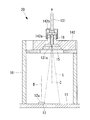
図3は、3個の光量検知装置1の外観を示している。光量検知装置1は、図4に示されるように、水平に配置される基板11と、基板11に実装された受光素子(受光部)12と、合波部22に接続されモニタ光を導光する光量検知用光ファイバ13と、光量検知用光ファイバ13を保持するホルダ(調整部)14と、光量検知用光ファイバ13から射出されたモニタ光から検知対象の色のモニタ光を選択する光学フィルタ15と、ホルダ14を基板11に固定するとともに受光素子12の周囲を遮光するためのフレーム16と、受光素子12によって検出された受光量を表示するモニタ(表示部)17とを備えている。光量検知装置1の略全体が、遮光性の箱型のカバー8(図3参照。)によって覆われている。
図3は、3個の光量検知装置1の外観を示している。光量検知装置1は、図4に示されるように、水平に配置される基板11と、基板11に実装された受光素子(受光部)12と、合波部22に接続されモニタ光を導光する光量検知用光ファイバ13と、光量検知用光ファイバ13を保持するホルダ(調整部)14と、光量検知用光ファイバ13から射出されたモニタ光から検知対象の色のモニタ光を選択する光学フィルタ15と、ホルダ14を基板11に固定するとともに受光素子12の周囲を遮光するためのフレーム16と、受光素子12によって検出された受光量を表示するモニタ(表示部)17とを備えている。光量検知装置1の略全体が、遮光性の箱型のカバー8(図3参照。)によって覆われている。
基板11は、受光素子12から出力された電気信号を処理するための回路が形成されたプリント基板であり、モニタ17と電気的に接続されている。
受光素子12は、例えばPDまたはアバランシェフォトダイオード(APD)であり、上方を向いて配置されモニタ光を受光する受光面12aを有している。受光素子12は、受光面12aで受光したモニタ光を光電変換することで受光量に相当する電気信号を生成する。電気信号は、基板11の回路によって処理されて検知信号Sr、SgまたはSbに生成される。検知信号Sr、SgまたはSbは、上述したように光源制御部23に送信されるとともに、検知信号Sr、SgまたはSbが示す受光量の値がモニタ17に表示されるようになっている。モニタ17は、表示部7と同一の表示装置であってもよく、表示部7とは別体の表示装置であってもよい。
光量検知用光ファイバ13は遮光性の外皮によって被覆されており、両端の入射端面および射出端面13a以外の部分からはモニタ光が外側に漏れないようになっている。光量検知用光ファイバ13の入射端面は合波部22に接続され、合波部22内でレーザ光から分岐されたモニタ光が光量検知用光ファイバ13の入射端面に入射するように構成されている。
例えば、合波部22内で合波された後のレーザ光の一部がビームスプリッタ等で分岐され、分岐されたレーザ光がさらに3つに分割されて3本の光量検知用光ファイバ13の入射端面に入射するように構成される。
あるいは、合波前の各レーザ光の一部が、各光源21R,21G,21Bと合波部22との間で、または合波部22内で分岐されて入射端面に入射するように構成されていてもよい。このように、合波前のレーザ光の一部をモニタ光Lとして使用する場合には、フィルタ15は設けられていなくてもよい。
あるいは、合波前の各レーザ光の一部が、各光源21R,21G,21Bと合波部22との間で、または合波部22内で分岐されて入射端面に入射するように構成されていてもよい。このように、合波前のレーザ光の一部をモニタ光Lとして使用する場合には、フィルタ15は設けられていなくてもよい。
光量検知用光ファイバ13の射出端面13aは、光量検知用光ファイバ13の光軸Aに対して傾斜しており、射出端面13aからは、光軸Aに対して斜め方向にモニタ光Lが発散光束として射出される。光量検知用光ファイバ13の先端部は、光軸Aと同軸に配置された円筒状のフェルール18によって被覆されている。
ホルダ14は、フェルール18が長手方向に嵌合する円柱状の嵌合孔14aを有している。フェルール18は、嵌合孔14a内に長手軸回りに連続的に滑らかに回転可能に嵌合しており、これにより、光量検知用光ファイバ13は、光軸A回りに連続的に滑らかに回転可能にホルダ14によって保持されている。
フレーム16は、基板11上に直立し基板11に固定された筒状の遮光性の部材である。受光面12aに検知対象のモニタ光L以外の光が周囲から入射しないように、受光素子12の周囲がフレーム16によって覆われている。ホルダ14はフレーム16内の上部に固定ねじ16aによって固定されている。ホルダ14は、光量検知用光ファイバ13の光軸Aと受光面12aの光軸Bが相互に略平行となり、かつ相互に偏心するように、また、射出端面13aおよび受光面12aが光軸A,Bに沿う方向に間隔を空けて相互に略対向するように、光量検知用光ファイバ13を保持している。受光面12aの光軸Bとは、受光面12aの中心を通り受光面12aに垂直な軸である。
フェルール18の基端部は、図3に示されるように、カバー8の天井を貫通してカバー8の外側に突出している。操作者は、フェルール18の基端部を把持して手動で操作することで、カバー8内の光量検知用光ファイバ13を光軸A回りに回転させることができる。また、ホルダ14を貫通してフレーム16の外側からフェルール18の外周面まで挿入された固定ねじ16bによって、フェルール18および光量検知用光ファイバ13を任意の回転角度でホルダ14およびフレーム16に対して固定することができるようになっている。
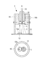
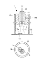
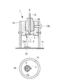
光軸Aに対して傾斜する射出端面13aからは、光軸Aに対して斜め方向にモニタ光Lが射出される。したがって、図5Aから図5Cに示されるように、光量検知用光ファイバ13の光軸A回りの回転によって射出端面13aから射出されるモニタ光Lが光軸A回りに回転移動し、それにより、基板11上においてモニタ光Lのスポットが光軸A回りに回転移動する。光軸Aは受光面12aの光軸Bに対して偏心しているので、スポットの回転移動によってスポットが受光面12aと重なる面積が変化し、受光面12aにおけるモニタ光Lの受光量が変化する。なお、図5Aから図5Cにおいて、図面を簡略にするために、一部の符号を省略している。
ここで、モニタ光Lの光軸Cが受光面12aの光軸Bから最も遠くに配置されたときに(図5A参照。)、スポットが受光面12aと重なる面積が略ゼロとなり、モニタ光Lの光軸Cが受光面12aの光軸Bの最も近くに配置されたときに(図5C参照。)、スポットが受光面12aの全範囲と重なるように、光軸A,B間の距離や射出端面13aの傾斜角度等が設計されている。図5Aから図5Cにおいて、上段は、光量検知装置1の縦断面図を示し、下段は、基板11および受光面12aを上方から見た平面図を示している。
次に、このように構成された光量検知装置1および光走査型内視鏡装置100の作用について説明する。
本実施形態に係る光量検知装置1および光走査型内視鏡装置100によれば、光源21R、21Gまたは21Bから出力されたレーザ光の一部がモニタ光Lとして対応する光量検知用光ファイバ13によって導光され、フレーム16内で射出端面13aから受光面12aへ向けて射出される。受光面12aにおけるモニタ光Lの受光量は受光素子12によって検出され、検出された受光量がモニタ17に表示される。
本実施形態に係る光量検知装置1および光走査型内視鏡装置100によれば、光源21R、21Gまたは21Bから出力されたレーザ光の一部がモニタ光Lとして対応する光量検知用光ファイバ13によって導光され、フレーム16内で射出端面13aから受光面12aへ向けて射出される。受光面12aにおけるモニタ光Lの受光量は受光素子12によって検出され、検出された受光量がモニタ17に表示される。
光源21R、21Gまたは21Bからのレーザ光の出力光量と、光量検知用光ファイバ13に分岐されるモニタ光Lの光量との比は、一定である。したがって、モニタ17に表示された受光量に基づいて、操作者は、光源21R、21Gまたは21Bの出力光量をモニタリングすることができる。また、モニタ光Lの受光量に基づく検知信号Sr、SgまたはSbが受光素子12から光源制御部23に送信され、被検体Sに照射される照明光の光量が適正範囲内となるように検知信号Sr、SgまたはSbに基づいて光源21R、21Gまたは21Bの出力光量が調整される。
ここで、モニタ17に表示される受光量が、受光素子12の受光量の適正範囲に対して多いまたは少ないときには、操作者は、固定ねじ16bを緩め、続いて、モニタ17に表示される受光量を確認しながらカバー8の外側に突出するフェルールの18の基端部を回転させることで、受光素子12によるモニタ光Lの受光量を適正量に調整することができる。すなわち、操作者は、フェルール18の基端部の回転によって光量検知用光ファイバ13を回転させ、それによって、射出端面13aから射出されるモニタ光Lの受光面12aとの重なり量を減少または増大させることができる。
このように、本実施形態によれば、光軸A回りの光量検知用光ファイバ13の回転によってモニタ光Lの光軸Cが受光面12aの光軸Bに対して偏心した光軸A回りに回転移動することで、モニタ光Lの光軸Cと受光面12aの光軸Bとの距離が光軸B,Cに交差する方向に変化する。これにより、射出端面13aと受光面12aとの光軸A,Bに沿う方向の距離の変更によって受光量を調整する場合と比べて、受光面12aでのモニタ光Lの受光量の調整範囲が拡大する。特に、受光量の調整範囲の下限が略ゼロまで拡大する。
したがって、光源21R、21Gまたは21Bからのレーザ光の出力光量に対するモニタ光Lの分岐比に光源部2毎の個体差があり、モニタ光Lの光量に光源部2間で大きなばらつきがあったとしても、このような光源部2の個体差に関わらず、受光素子12によるモニタ光Lの受光量を適正範囲内に収まるように調整することが可能となり、光源21R、21Gまたは21Bの出力光量を正確にモニタリングすることができるという利点がある。
また、フェルール18および光量検知用光ファイバ13が連続的に滑らかに回転可能であるので、モニタ光Lの光軸Cと受光面12aの光軸Bとの距離も連続的に変化し、受光素子12の受光量も連続的に変化する。これにより、受光量の微調整が容易となり、例えば、受光素子12の受光量の適正範囲が狭い場合であっても、モニタ光Lの受光量を適切に調整することができるという利点がある。
(第2の実施形態)
次に、本発明の第2の実施形態に係る光走査型内視鏡装置およびこれに搭載された光量検知装置10について図6Aから図7を参照して説明する。
本実施形態において、第1の実施形態と異なる構成について説明し、第1の実施形態と共通する構成については同一の符号を付して説明を省略する。
本実施形態に係る光走査型内視鏡装置は、光量検知装置1に代えて光量検知装置10を備えることを除いて、第1の実施形態と同一である。
次に、本発明の第2の実施形態に係る光走査型内視鏡装置およびこれに搭載された光量検知装置10について図6Aから図7を参照して説明する。
本実施形態において、第1の実施形態と異なる構成について説明し、第1の実施形態と共通する構成については同一の符号を付して説明を省略する。
本実施形態に係る光走査型内視鏡装置は、光量検知装置1に代えて光量検知装置10を備えることを除いて、第1の実施形態と同一である。
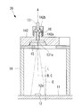
光量検知装置10は、図6Aおよび図6Bに示されるように、基板11と、受光素子12と、光量検知用光ファイバ131と、光量検知用光ファイバ131の射出端面131aを光軸Bに交差する揺動軸D回りに揺動させるための揺動治具(調整部)141と、光学フィルタ15と、フレーム16と、モニタ17とを備えている。図6Aから図7において、モニタ17の図示は省略されている。
光量検知用光ファイバ131は、光軸Aに対して垂直な射出端面131aを有することを除いて、第1の実施形態の光量検知用光ファイバ13と同様に構成されている。射出端面131aからは、光量検知用光ファイバ131の光軸Aと同軸の光軸Cに沿ってモニタ光Lが発散光束として射出される。
揺動治具141は、フェルール18が長手方向に嵌合する円柱状の嵌合孔141aを有している。フェルール18は、嵌合孔141a内に固定されており、これにより、光量検知用光ファイバ131は、揺動治具141に固定されている。揺動治具141は、射出端面131aおよび受光面12aが光軸A,Bに沿う方向に間隔を空けて相互に略対向するように、光量検知用光ファイバ131を保持している。符号141cは、フェルール18を揺動治具141に固定するためのねじである。
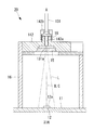
また、揺動治具141は、光軸Bに直交する揺動軸D回りに連続的に滑らかに揺動可能に、フレーム16に支持されている。符号141bは、揺動軸Dに沿って配置され揺動治具141を揺動可能にフレーム16と連結するピンである。射出端面131aは、当該射出端面131aが揺動中心となるように揺動軸D上に位置するとともに、受光面12aの光軸B上に位置している。これにより、揺動治具141の揺動によって射出端面131aが同一の位置で揺動し、図7に示されるように、射出端面131aから射出されるモニタ光が光軸Bを含む平面内で揺動する。このときに、基板11上においては、モニタ光Lのスポットが受光面12aの光軸Bに略直交する方向に直線移動することでスポットが受光面12aと重なる面積が変化し、受光素子12の受光量が変化する。
ここで、図7に示されるように、モニタ光Lの光軸Cが受光面12aの光軸Bから最も遠くに配置されたときに、スポットが受光面12aと重なる面積が略ゼロとなるように、揺動治具141の揺動角度範囲等が設計されている。
ここで、図7に示されるように、モニタ光Lの光軸Cが受光面12aの光軸Bから最も遠くに配置されたときに、スポットが受光面12aと重なる面積が略ゼロとなるように、揺動治具141の揺動角度範囲等が設計されている。
フェルール18の基端部は、カバー8の天井を貫通してカバー8の外側に突出している。操作者は、フェルール18の基端部を把持して手動で操作することで、カバー8内の揺動治具141および光量検知用光ファイバ131を揺動軸D回りに揺動させることができる。また、フレーム16には円弧状のスリットが形成されており、スリットを介してフレーム16の外側から揺動治具141内に挿入された固定ねじ16cによって、揺動治具141および光量検知用光ファイバ131を任意の揺動角度でフレーム16に対して固定することができるようになっている。
次に、このように構成された光量検知装置10の作用について説明する。
本実施形態に係る光量検知装置10によれば、モニタ17に表示される受光量が、受光素子12の受光量の適正範囲に対して多いまたは少ないときには、操作者は、固定ねじ16cを緩め、モニタ17に表示される受光量を確認しながらカバー8の外側に突出するフェルールの18の基端部を揺動させることで、受光素子12によるモニタ光Lの受光量を適正量に調整することができる。すなわち、操作者は、フェルール18の基端部の揺動によって光量検知用光ファイバ131を揺動させ、それによって、射出端面131aから射出されるモニタ光Lの受光面12aとの重なり量を減少または増大させることができる。
本実施形態に係る光量検知装置10によれば、モニタ17に表示される受光量が、受光素子12の受光量の適正範囲に対して多いまたは少ないときには、操作者は、固定ねじ16cを緩め、モニタ17に表示される受光量を確認しながらカバー8の外側に突出するフェルールの18の基端部を揺動させることで、受光素子12によるモニタ光Lの受光量を適正量に調整することができる。すなわち、操作者は、フェルール18の基端部の揺動によって光量検知用光ファイバ131を揺動させ、それによって、射出端面131aから射出されるモニタ光Lの受光面12aとの重なり量を減少または増大させることができる。
このように、本実施形態によれば、光軸Bに交差する揺動軸D回りの射出端面131aの揺動によってモニタ光Lの光軸Cが受光面12aの光軸Bを含む平面内で揺動することで、モニタ光Lの光軸Cと受光面12aの光軸Bとの距離が光軸B,Cに交差する方向に変化する。これにより、受光面12aでのモニタ光Lの受光量の調整範囲を拡大することができ、特に、受光量の調整範囲の下限を略ゼロまで拡大することができる。また、射出端面131aが連続的に滑らかに揺動可能であるので、モニタ光Lの光軸Cと受光面12aの光軸Bとの距離も連続的に変化し、受光素子12の受光量も連続的に変化する。これにより、受光量の微調整も容易に行うことができる。
(第3の実施形態)
次に、本発明の第3の実施形態に係る光走査型内視鏡装置およびこれに搭載された光量検知装置20について図8Aから図10を参照して説明する。
本実施形態において、第1および第2の実施形態と異なる構成について説明し、第1および第2の実施形態と共通する構成については同一の符号を付して説明を省略する。
本実施形態に係る光走査型内視鏡装置は、光量検知装置1に代えて光量検知装置20を備えることを除いて、第1の実施形態と同一である。
次に、本発明の第3の実施形態に係る光走査型内視鏡装置およびこれに搭載された光量検知装置20について図8Aから図10を参照して説明する。
本実施形態において、第1および第2の実施形態と異なる構成について説明し、第1および第2の実施形態と共通する構成については同一の符号を付して説明を省略する。
本実施形態に係る光走査型内視鏡装置は、光量検知装置1に代えて光量検知装置20を備えることを除いて、第1の実施形態と同一である。
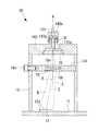
光量検知装置20は、図8Aおよび図8Bに示されるように、基板11と、受光素子12と、光量検知用光ファイバ131と、光量検知用光ファイバ131を光軸Bに交差する方向に平行移動させるためのシフト治具(調整部)142と、光学フィルタ15と、シフト治具142を基板11に固定するためのフレーム16と、モニタ17とを備えている。図8Aから図10において、モニタ17の図示は省略されている。
シフト治具142は、フェルール18が長手方向に嵌合する円柱状の嵌合孔142aを有している。フェルール18は、嵌合孔142a内に固定されており、これにより、光量検知用光ファイバ131は、シフト治具142に固定されている。符号142bは、フェルール18をシフト治具142に固定するためのねじである。
シフト治具142は、射出端面131aおよび受光面12aが光軸Aに沿う方向に間隔を空けて相互に略対向するように、光量検知用光ファイバ131を保持している。また、シフト治具142は、光軸Bに交差する方向に連続的に滑らかに平行移動可能に、フレーム16に支持されている。シフト治具142の平行移動によって、図9に示されるように、射出端面131aから射出されるモニタ光Lが光軸Bに交差する方向に平行移動する。このときに、基板11上においては、モニタ光Lのスポットが受光面12aの光軸Bに交差する方向に直線移動することでスポットが受光面12aと重なる面積が変化し、受光素子12の受光量が変化する。
ここで、図9に示されるように、モニタ光Lの光軸Cが受光面12aの光軸Bから最も遠くに配置されたときに、スポットが受光面12aと重なる面積が略ゼロとなり、モニタ光Lの光軸Cが受光面12aの光軸Bの最も近くに配置されたときに、スポットが受光面12aの全範囲と重なるように、光軸A,B間の距離や光軸A,Bの相対位置等が設計されている。
フェルール18の基端部は、カバー8の天井を貫通してカバー8の外側に突出している。操作者は、フェルール18の基端部を把持して手動で操作することで、カバー8内のシフト治具142および光量検知用光ファイバ131を光軸Bに交差する方向に平行移動させることができる。また、フレーム16には光軸Bに交差する方向に延びるスリットが形成されており、スリットを介してフレーム16の外側からシフト治具142内に挿入された固定ねじ16dによって、シフト治具142および光量検知用光ファイバ131を任意の位置でフレーム16に対して固定することができるようになっている。
次に、このように構成された光量検知装置20の作用について説明する。
本実施形態に係る光量検知装置20によれば、モニタ17に表示される受光量が、受光素子12の受光量の適正範囲に対して多いまたは少ないときには、操作者は、固定ねじ16dを緩め、モニタ17に表示される受光量を確認しながらカバー8の外側に突出するフェルールの18の基端部を平行移動させることで、受光素子12によるモニタ光Lの受光量を適正量に調整することができる。すなわち、操作者は、フェルール18の基端部の平行移動によって光量検知用光ファイバ131を平行移動させ、それによって、射出端面131aから射出されるモニタ光Lの受光面12aとの重なり量を減少または増大させることができる。
本実施形態に係る光量検知装置20によれば、モニタ17に表示される受光量が、受光素子12の受光量の適正範囲に対して多いまたは少ないときには、操作者は、固定ねじ16dを緩め、モニタ17に表示される受光量を確認しながらカバー8の外側に突出するフェルールの18の基端部を平行移動させることで、受光素子12によるモニタ光Lの受光量を適正量に調整することができる。すなわち、操作者は、フェルール18の基端部の平行移動によって光量検知用光ファイバ131を平行移動させ、それによって、射出端面131aから射出されるモニタ光Lの受光面12aとの重なり量を減少または増大させることができる。
このように、本実施形態によれば、光軸Bに交差する方向の光量検知用光ファイバ131の平行移動によってモニタ光Lの光軸Cが光軸Bに交差する方向に平行移動することで、モニタ光Lの光軸Cと受光面12aの光軸Bとの距離が光軸B,Cに交差する方向に変化する。これにより、受光面12aでのモニタ光Lの受光量の調整範囲を拡大することができ、特に、受光量の調整範囲の下限を略ゼロまで拡大することができる。また、射出端面131aが連続的に滑らかに平行移動可能であるので、モニタ光Lの光軸Cと受光面12aの光軸Bとの距離も連続的に変化し、受光素子12の受光量も連続的に変化する。これにより、受光量の微調整も容易に行うことができる。
本実施形態においては、シフト治具142を光軸Bに交差する方向に平行移動させることとしたが、これに代えて、図10に示されるように、光量検知用光ファイバ131の光軸Aおよび受光面12aの光軸Bの両方に対して偏心した回転軸E回りにシフト治具142を回転させてもよい。回転軸Eは、フレーム16の中心軸と一致していることが好ましい。シフト治具142の回転によって、第1の実施形態と同様に、モニタ光Lの光軸Cが受光面12aの光軸Bに対して偏心した回転軸E回りに回転移動する。したがって、このようにしても、シフト治具142を平行移動させたときと同一の効果を得ることができる。
(第4の実施形態)
次に、本発明の第4の実施形態に係る光走査型内視鏡装置およびこれに搭載された光量検知装置30について図11Aおよび図11Bを参照して説明する。
本実施形態において、第1から第3の実施形態と異なる構成について説明し、第1から第3の実施形態と共通する構成については同一の符号を付して説明を省略する。
本実施形態に係る光走査型内視鏡装置は、光量検知装置1に代えて光量検知装置30を備えることを除いて、第1の実施形態と同一である。
次に、本発明の第4の実施形態に係る光走査型内視鏡装置およびこれに搭載された光量検知装置30について図11Aおよび図11Bを参照して説明する。
本実施形態において、第1から第3の実施形態と異なる構成について説明し、第1から第3の実施形態と共通する構成については同一の符号を付して説明を省略する。
本実施形態に係る光走査型内視鏡装置は、光量検知装置1に代えて光量検知装置30を備えることを除いて、第1の実施形態と同一である。
光量検知装置30は、図11Aおよび図11Bに示されるように、基板11と、受光素子12と、光量検知用光ファイバ131と、光量検知用光ファイバ131を保持するホルダ143と、光学フィルタ15と、ホルダ143を基板11に固定するためのフレーム16と、モニタ17と、射出端面131aと受光面12aとの間に配置されたリズナープリズム(調整部)19とを備えている。図11Aおよび図11Bにおいて、モニタ17の図示は省略されている。
ホルダ143は、フェルール18が長手方向に嵌合する円柱状の嵌合孔143aを有している。フェルール18は、嵌合孔143a内に固定されており、これにより、光量検知用光ファイバ131は、ホルダ143に固定されている。ホルダ143は、射出端面131aおよび受光面12aが光軸Aに沿う方向に間隔を空けて相互に対向するように、かつ、光量検知用光ファイバ131の光軸Aおよび受光面12aの光軸Bが相互に偏心するように、光量検知用光ファイバ131を保持している。符号143bは、フェルール18をホルダ143に固定するためのねじである。
リズナープリズム19は、射出端面131a側に配置され光軸Aに対して垂直な入射面19aと、受光面12a側に配置され光軸Aに対して傾斜した偏向面19bとを有する楔形のプリズムである。光軸Aに沿って入射面19aに入射したモニタ光Lは、光軸Aに傾斜する方向に偏向されて偏向面19bから射出されるようになっている。
リズナープリズム19の周縁は環状の回転板(調整部)144によって保持され、回転板144は光軸Aに略平行な回転軸F回りに連続的に滑らかに回転可能にフレーム16に支持されている。図11Aおよび図11Bでは回転軸Fが光軸Aと一致しているが、回転軸Fは光軸Aに対して偏心していてもよい。回転板144の周方向の一部分は、カバー8の側壁を貫通してカバー8の外側に突出している。操作者は、回転板144の周縁を手動で操作することで、カバー8内の回転板144およびリズナープリズム19を回転軸F回りに回転させることができる。また、フレーム16に周方向に延びるスリットが形成されており、スリットを介してフレーム16の外側から回転板144内に挿入された固定ねじ16eによって、回転板144およびリズナープリズム19を任意の回転角度でフレーム16に対して固定することができるようになっている。
リズナープリズム19の回転軸F回りの回転によって偏向面19bから射出されるモニタ光Lが光軸A回りに回転移動し、それにより、基板11上においてモニタ光Lのスポットが光軸A回りに回転移動する。光軸Aは受光面12aの光軸Bに対して偏心しているので、スポットの回転移動によってスポットが受光面12aと重なる面積が変化し、受光面12aにおけるモニタ光Lの受光量が変化する。
ここで、モニタ光Lの光軸Cが受光面12aの光軸Bから最も遠くに配置されたときに(図11B参照。)、スポットが受光面12aと重なる面積が略ゼロとなり、モニタ光Lの光軸Cが受光面12aの光軸Bの最も近くに配置されたときに(図11A参照。)、スポットが受光面12aの全範囲と重なるように、光軸A,B間の距離やリズナープリズム19の偏向面19bの傾斜角度等が設計されている。
次に、このように構成された光量検知装置30の作用について説明する。
本実施形態に係る光量検知装置30によれば、モニタ17に表示される受光量が、受光素子12の受光量の適正範囲に対して多いまたは少ないときには、操作者は、固定ねじ16eを緩め、モニタ17に表示される受光量を確認しながらカバー8の外側に突出する回転板144の周縁を回転させることで、受光素子12によるモニタ光Lの受光量を適正量に調整することができる。すなわち、操作者は、回転板144の回転によってリズナープリズム19を回転させ、それによって、リズナープリズム19の偏向面19bから射出されるモニタ光Lの受光面12aとの重なり量を減少または増大させることができる。
本実施形態に係る光量検知装置30によれば、モニタ17に表示される受光量が、受光素子12の受光量の適正範囲に対して多いまたは少ないときには、操作者は、固定ねじ16eを緩め、モニタ17に表示される受光量を確認しながらカバー8の外側に突出する回転板144の周縁を回転させることで、受光素子12によるモニタ光Lの受光量を適正量に調整することができる。すなわち、操作者は、回転板144の回転によってリズナープリズム19を回転させ、それによって、リズナープリズム19の偏向面19bから射出されるモニタ光Lの受光面12aとの重なり量を減少または増大させることができる。
このように、本実施形態によれば、リズナープリズム19の回転軸F回りに回転によってモニタ光Lの光軸Cが受光面12aの光軸Bに対して偏心した光軸A回りに回転移動することで、モニタ光Lの光軸Cと受光面12aの光軸Bとの距離が光軸B,Cに交差する方向に変化する。これにより、受光面12aでのモニタ光Lの受光量の調整範囲を拡大することができ、特に、受光量の調整範囲の下限を略ゼロまで拡大することができる。また、リズナープリズム19が連続的に滑らかに回転可能であるので、モニタ光Lの光軸Cと受光面12aの光軸Bとの距離も連続的に変化し、受光素子12の受光量も連続的に変化する。これにより、受光量の微調整も容易に行うことができる。
上述した第1から第4の実施形態においては、操作者が、モニタ17に表示された受光量をモニタリングしながら受光素子12による受光量を手動調整することとしたが、これに代えて、受光量が適正範囲内に自動調整されるように構成されていてもよい。
この場合、光量検知装置1,10,20,30には、光量検知用光ファイバ13,131を回転、揺動、平行移動させるための、またはリズナープリズム19を回転させるためのモータと、受光素子12からの検知信号Sr、SgまたはSbに基づいてモータを制御する制御装置とが設けられる。制御装置は、検知信号Sr、SgまたはSbが示す受光量が予め設定された適正値となるようにモータを駆動する。
この場合、光量検知装置1,10,20,30には、光量検知用光ファイバ13,131を回転、揺動、平行移動させるための、またはリズナープリズム19を回転させるためのモータと、受光素子12からの検知信号Sr、SgまたはSbに基づいてモータを制御する制御装置とが設けられる。制御装置は、検知信号Sr、SgまたはSbが示す受光量が予め設定された適正値となるようにモータを駆動する。
1,10,20,30 光量検知装置
12 受光素子(受光部)
12a 受光面
13 光量検知用光ファイバ(光ファイバ)
14 ホルダ(調整部)
141 揺動治具(調整部)
142 シフト治具(調整部)
144 回転板(調整部)
17 モニタ(表示部)
19 リズナープリズム(調整部)
12 受光素子(受光部)
12a 受光面
13 光量検知用光ファイバ(光ファイバ)
14 ホルダ(調整部)
141 揺動治具(調整部)
142 シフト治具(調整部)
144 回転板(調整部)
17 モニタ(表示部)
19 リズナープリズム(調整部)
Claims (8)
- 光源から出力された光の一部を導光して射出端面から射出する光ファイバと、
該光ファイバの前記射出端面と略対向して配置された受光面を有し、該受光面で受光された前記一部の光の受光量を検出する受光部と、
前記受光面で受光される前記一部の光の受光量を調整する調整部とを備え、
該調整部が、前記射出端面から射出された前記一部の光の光軸と、前記受光面の中心を通り前記受光面に垂直な前記受光面の光軸との距離を変更する光量検知装置。 - 前記受光部によって検出された前記受光量を表示する表示部を備える請求項1に記載の光量検知装置。
- 前記調整部が、前記距離を連続的に変更することで前記受光量を連続的に調整可能である請求項1または請求項2に記載の光量検知装置。
- 前記光ファイバの前記射出端面が、該光ファイバの光軸に対して傾斜し、
前記光ファイバの光軸および前記受光面の光軸が、相互に偏心し、
前記調整部が、前記光ファイバを該光ファイバの光軸回りに回転させる請求項1から請求項3のいずれかに記載の光量検知装置。 - 前記調整部が、前記射出端面を前記受光面の光軸に交差する方向の揺動軸回りに揺動させる請求項1から請求項3のいずれかに記載の光量検知装置。
- 前記調整部が、前記光ファイバを前記受光面の光軸に交差する方向に平行移動させる請求項1から請求項3のいずれかに記載の光量検知装置。
- 前記調整部が、前記受光面の光軸および前記光ファイバの光軸に対して偏心した回転軸回りに前記光ファイバを回転移動させる請求項1から請求項3のいずれかに記載の光量検知装置。
- 前記光ファイバの前記射出端面と前記受光面との間に配置され、前記射出端面から入射した前記一部の光を偏向するリズナープリズムを備え、
前記光ファイバの光軸および前記受光面の光軸が、相互に偏心し、
前記調整部が、前記リズナープリズムを前記光ファイバの光軸に平行な回転軸回りに回転させる請求項1から請求項3のいずれかに記載の光量検知装置。
Priority Applications (1)
| Application Number | Priority Date | Filing Date | Title |
|---|---|---|---|
| PCT/JP2017/020687 WO2018220847A1 (ja) | 2017-06-02 | 2017-06-02 | 光量検知装置 |
Applications Claiming Priority (1)
| Application Number | Priority Date | Filing Date | Title |
|---|---|---|---|
| PCT/JP2017/020687 WO2018220847A1 (ja) | 2017-06-02 | 2017-06-02 | 光量検知装置 |
Publications (1)
| Publication Number | Publication Date |
|---|---|
| WO2018220847A1 true WO2018220847A1 (ja) | 2018-12-06 |
Family
ID=64455355
Family Applications (1)
| Application Number | Title | Priority Date | Filing Date |
|---|---|---|---|
| PCT/JP2017/020687 Ceased WO2018220847A1 (ja) | 2017-06-02 | 2017-06-02 | 光量検知装置 |
Country Status (1)
| Country | Link |
|---|---|
| WO (1) | WO2018220847A1 (ja) |
Citations (4)
| Publication number | Priority date | Publication date | Assignee | Title |
|---|---|---|---|---|
| JPS5723907A (en) * | 1980-07-21 | 1982-02-08 | Ricoh Co Ltd | Optical device using optical fiber and adjustable in quantity of light |
| JP2004310029A (ja) * | 2002-11-26 | 2004-11-04 | Lg Electronics Inc | 可変光減衰器を利用した光受信器及び光送信器並びにその可変光減衰器の製造方法 |
| JP2009244833A (ja) * | 2008-03-10 | 2009-10-22 | Nippon Telegr & Teleph Corp <Ntt> | 可変光減衰器を内蔵した光受信器 |
| JP2017056104A (ja) * | 2015-09-18 | 2017-03-23 | オリンパス株式会社 | 光量検知装置 |
-
2017
- 2017-06-02 WO PCT/JP2017/020687 patent/WO2018220847A1/ja not_active Ceased
Patent Citations (4)
| Publication number | Priority date | Publication date | Assignee | Title |
|---|---|---|---|---|
| JPS5723907A (en) * | 1980-07-21 | 1982-02-08 | Ricoh Co Ltd | Optical device using optical fiber and adjustable in quantity of light |
| JP2004310029A (ja) * | 2002-11-26 | 2004-11-04 | Lg Electronics Inc | 可変光減衰器を利用した光受信器及び光送信器並びにその可変光減衰器の製造方法 |
| JP2009244833A (ja) * | 2008-03-10 | 2009-10-22 | Nippon Telegr & Teleph Corp <Ntt> | 可変光減衰器を内蔵した光受信器 |
| JP2017056104A (ja) * | 2015-09-18 | 2017-03-23 | オリンパス株式会社 | 光量検知装置 |
Similar Documents
| Publication | Publication Date | Title |
|---|---|---|
| JP2010117442A (ja) | 光走査型内視鏡、光走査型内視鏡プロセッサ、および光走査型内視鏡装置 | |
| US8466956B2 (en) | Scanning endoscope processor and scanning endoscope apparatus | |
| JP6419893B1 (ja) | 半導体検査装置 | |
| US8226551B2 (en) | Scanning endoscope, scanning endoscope processor, and scanning endoscope apparatus | |
| JPH02146514A (ja) | 光学装置 | |
| JP2004519697A (ja) | 光学測距装置 | |
| US11402200B2 (en) | Measuring device, observing device and measuring method | |
| US8772688B2 (en) | Autofocus device including line image forming unit and rotation unit that rotates line image | |
| WO2017033419A1 (ja) | 物質検出装置、物質検出システム及び物質検出方法 | |
| US20170311779A1 (en) | Optical scanning endoscope apparatus | |
| JP2011002439A (ja) | 検査装置 | |
| US10488647B2 (en) | Method for measuring scanning pattern of optical scanning apparatus, apparatus for measuring scanning pattern, and method for calibrating image | |
| JP2010142570A (ja) | 内視鏡光学系 | |
| JP2010014837A (ja) | 光走査顕微鏡 | |
| WO2018220847A1 (ja) | 光量検知装置 | |
| JPH1068901A (ja) | 2次元スキャナ装置 | |
| JP7154293B2 (ja) | 内視鏡システム | |
| JP2017107082A (ja) | 光走査装置、光走査方法および表面検査装置 | |
| JP6599722B2 (ja) | 検査装置 | |
| JP2017056104A (ja) | 光量検知装置 | |
| JP2008256497A (ja) | 計測装置 | |
| KR101202977B1 (ko) | 대상체의 표면과 내부 구조를 동시에 관찰 가능한 하이브리드 현미경 | |
| JP2016110004A (ja) | レーザ顕微鏡 | |
| JP2007140196A (ja) | 光源装置とこれを有するレーザ顕微鏡。 | |
| JP6173035B2 (ja) | 光走査デバイス、光走査型観察装置および光走査型画像表示装置 |
Legal Events
| Date | Code | Title | Description |
|---|---|---|---|
| 121 | Ep: the epo has been informed by wipo that ep was designated in this application |
Ref document number: 17911508 Country of ref document: EP Kind code of ref document: A1 |
|
| NENP | Non-entry into the national phase |
Ref country code: DE |
|
| 122 | Ep: pct application non-entry in european phase |
Ref document number: 17911508 Country of ref document: EP Kind code of ref document: A1 |
|
| NENP | Non-entry into the national phase |
Ref country code: JP |