WO2018216367A1 - 成形型および成形方法 - Google Patents
成形型および成形方法 Download PDFInfo
- Publication number
- WO2018216367A1 WO2018216367A1 PCT/JP2018/014760 JP2018014760W WO2018216367A1 WO 2018216367 A1 WO2018216367 A1 WO 2018216367A1 JP 2018014760 W JP2018014760 W JP 2018014760W WO 2018216367 A1 WO2018216367 A1 WO 2018216367A1
- Authority
- WO
- WIPO (PCT)
- Prior art keywords
- mold
- molding surface
- molding
- resin
- die
- Prior art date
- Legal status (The legal status is an assumption and is not a legal conclusion. Google has not performed a legal analysis and makes no representation as to the accuracy of the status listed.)
- Ceased
Links
Images








Classifications
-
- B—PERFORMING OPERATIONS; TRANSPORTING
- B29—WORKING OF PLASTICS; WORKING OF SUBSTANCES IN A PLASTIC STATE IN GENERAL
- B29C—SHAPING OR JOINING OF PLASTICS; SHAPING OF MATERIAL IN A PLASTIC STATE, NOT OTHERWISE PROVIDED FOR; AFTER-TREATMENT OF THE SHAPED PRODUCTS, e.g. REPAIRING
- B29C45/00—Injection moulding, i.e. forcing the required volume of moulding material through a nozzle into a closed mould; Apparatus therefor
- B29C45/17—Component parts, details or accessories; Auxiliary operations
- B29C45/26—Moulds
- B29C45/37—Mould cavity walls, i.e. the inner surface forming the mould cavity, e.g. linings
- B29C45/372—Mould cavity walls, i.e. the inner surface forming the mould cavity, e.g. linings provided with means for marking or patterning, e.g. numbering articles
-
- B—PERFORMING OPERATIONS; TRANSPORTING
- B29—WORKING OF PLASTICS; WORKING OF SUBSTANCES IN A PLASTIC STATE IN GENERAL
- B29C—SHAPING OR JOINING OF PLASTICS; SHAPING OF MATERIAL IN A PLASTIC STATE, NOT OTHERWISE PROVIDED FOR; AFTER-TREATMENT OF THE SHAPED PRODUCTS, e.g. REPAIRING
- B29C33/00—Moulds or cores; Details thereof or accessories therefor
- B29C33/42—Moulds or cores; Details thereof or accessories therefor characterised by the shape of the moulding surface, e.g. ribs or grooves
-
- B—PERFORMING OPERATIONS; TRANSPORTING
- B29—WORKING OF PLASTICS; WORKING OF SUBSTANCES IN A PLASTIC STATE IN GENERAL
- B29C—SHAPING OR JOINING OF PLASTICS; SHAPING OF MATERIAL IN A PLASTIC STATE, NOT OTHERWISE PROVIDED FOR; AFTER-TREATMENT OF THE SHAPED PRODUCTS, e.g. REPAIRING
- B29C45/00—Injection moulding, i.e. forcing the required volume of moulding material through a nozzle into a closed mould; Apparatus therefor
- B29C45/0025—Preventing defects on the moulded article, e.g. weld lines, shrinkage marks
-
- B—PERFORMING OPERATIONS; TRANSPORTING
- B29—WORKING OF PLASTICS; WORKING OF SUBSTANCES IN A PLASTIC STATE IN GENERAL
- B29C—SHAPING OR JOINING OF PLASTICS; SHAPING OF MATERIAL IN A PLASTIC STATE, NOT OTHERWISE PROVIDED FOR; AFTER-TREATMENT OF THE SHAPED PRODUCTS, e.g. REPAIRING
- B29C45/00—Injection moulding, i.e. forcing the required volume of moulding material through a nozzle into a closed mould; Apparatus therefor
- B29C45/17—Component parts, details or accessories; Auxiliary operations
- B29C45/26—Moulds
- B29C45/37—Mould cavity walls, i.e. the inner surface forming the mould cavity, e.g. linings
Definitions
- the present invention relates to a mold and a molding method.
- Patent Document 1 described above prevents molding defects such as deformation by changing the size of the gap of the film gate, which is a resin introduction portion in the mold, from the upstream side to the downstream side in the resin inflow direction.
- it has no effect on uneven gloss caused by oil precipitation as described above.
- it since it is necessary to lengthen the part to which the magnitude
- Patent Document 2 pays attention to gloss unevenness due to disturbance of the flow of the resin injected into the cavity in the mold, and the flow is caused by a lattice-like structure provided in the mold. Although control is disclosed, there is no effect on gloss unevenness caused by factors other than resin flow, such as oil precipitation.
- Patent Document 3 a glossing agent made of a special silica gel is added to a resin that is a raw material of a resin molded product, or a coating containing a matting agent is coated on the surface of the resin molded product, so that the gloss is increased.
- a glossing agent made of a special silica gel is added to a resin that is a raw material of a resin molded product, or a coating containing a matting agent is coated on the surface of the resin molded product, so that the gloss is increased.
- it does not eliminate the cause of gloss unevenness.
- the cost of the matting agent itself, the cost associated with the addition work or the coating work, and the need for safety measures such as prevention of ignition to the solvent arise.
- an object of the present invention is to provide a molding die and a molding method capable of suppressing gloss unevenness based on new knowledge obtained as a result of intensive studies by the present inventors.
- the mold of the present invention has a first mold and a second mold that are relatively close to and away from each other.
- the first mold has a first molding surface including a texture with fine irregularities formed on the surface
- the second mold has a second molding surface that forms a cavity between the first molding surface and the adjacent first molding surface.
- fine irregularities are formed on at least a portion facing the embossed surface in a state where the first mold and the second mold are closed.
- the molding method of the present invention includes a first mold having a first molding surface on which wrinkles are formed, and a second molding surface on which fine irregularities facing the wrinkles are formed at least in part. And close the second mold with
- resin is injected into a cavity formed between the first molding surface and the second molding surface, and pressure is applied to the resin in the cavity.
- molding method of this invention fills resin into the fine unevenness
- the mold 100 (molding mold) of the embodiment includes a first mold 110 and a second mold 120 that are relatively close to and away from each other.
- One of the first mold 110 and the second mold 120 is a movable mold that is connected to a driving unit such as a cylinder and is moved when the mold 100 is opened and closed, and the other is a fixed mold that is fixed.
- a driving unit such as a cylinder
- the present invention is not limited to this, and both of them may be moved to open and close the mold 100.
- the first mold 110 has a first molding surface 111 on which a texture 112 is formed. On the surface of the texture 112, fine irregularities 113 are formed.
- the second mold 120 has a second molding surface 121 that faces the first molding surface 111.
- the first mold 110 and the second mold 120 form a cavity 101 between the first molding surface 111 and the second molding surface 121 in a closed state.
- the cavity 101 communicates with a nozzle (not shown) for injecting resin. Further, a sealing member 102 made of, for example, a silicone resin is disposed around the cavity 101 between the first mold 110 and the second mold 120 to prevent leakage of the resin injected into the cavity 101. To prevent.
- the cavity 101 may communicate with, for example, a pump that exhausts the inside of the cavity 101.
- the gap between the first molding surface 111 and the second molding surface 121 is wider than the other general part 103, and the gap widens from the general part 103 to the enlarged part 104.
- the gap in the general portion 103 is, for example, 0.5 mm to 2.5 mm, but is not limited thereto.
- the gap in the enlarged portion 104 is, for example, 1.5 mm to 4.5 mm, but is not limited to this.
- the width of the changing portion 105 in the separating direction of the general portion 103 and the enlarged portion 104 is, for example, 20 mm to 160 mm, but is not limited thereto.
- fine irregularities 122 are formed on the second molding surface 121 so as to face the texture 112. Further, in the portion 106 adjacent to the removal changing portion 105 in the general portion 103, fine irregularities 122 are formed on the second molding surface 121 so as to face the texture 112.
- the width of the adjacent portion 106 in the adjacent direction between the general portion 103 and the removal portion 105 is, for example, 30 mm, but is not limited thereto.
- the fine unevenness 122 includes a deeper recess than the recess included in the fine unevenness 113.
- the depth of the concave portion included in the fine unevenness 113 is, for example, 5 to 30 ⁇ m.
- the depth of the concave portion included in the fine unevenness 122 is, for example, not less than the depth of the concave portion included in the fine unevenness 113 and not more than 60 ⁇ m, and preferably about twice the depth of the concave portion included in the fine unevenness 113. It is.
- the molding method of the present embodiment includes a mold clamping step S1, an injection step S2, a pressure holding step S3, a cooling step S4, and a demolding step S5.
- the mold clamping step S1 the first mold 110 and the second mold 120 are closed close to each other and the state is maintained.
- the injection step S2 resin is injected into the cavity 101.
- the resin is filled at a rate of, for example, about 90 to 95% with respect to the entire volume of the cavity 101 in order to prevent the mold 100 from being damaged.
- the resin in the cavity 101 is cooled and hardened.
- the cooling of the resin is performed by flowing a cooling medium such as cooling water through a circulation path provided inside the mold 100, for example.
- the first mold 110 and the second mold 120 are separated to open the mold 100, and the resin molded product is taken out.
- injection molding is performed in the same process as in the above embodiment, using a mold 100A different from that in the above embodiment.
- the injected resin 130 is the same in the above embodiment and the comparative example, and includes rubber 131 and oil 132.
- the resin 130 includes, for example, 20% or more of the oil 132, but is not limited thereto.
- the resin 130 may include other additives such as talc.
- the resin 130 examples include thermoplastic resins such as polypropylene (PP), polyamide (PA), polycarbonate (PC), polyethylene (PE), polystyrene (PS), acrylonitrile-butadiene-styrene plastic (ABS), and elastomer (rubber). It is.
- the resin 130 is injected in a state of being heated and having fluidity, and is filled, for example, while maintaining fluidity by heat from a heater provided in the mold 100 and the mold 100A.
- the rubber 131 is added so that a desired texture appears in the finished resin molded product.
- the oil 132 is added, for example, in order to increase the fluidity of the resin 130 or to improve the release property of the finished resin molded product.
- the first embodiment 110 and the comparative example share the first mold 110, but the comparative mold 100A has a second mold 120A different from the above embodiment.
- the second mold 120A differs from the above-described embodiment in that the fine unevenness 122 of the above-described embodiment is not provided and a smooth second molding surface 121A is formed, but the other configuration is the second of the above-described embodiment. This is the same as the mold 120.
- the gap 130 should be filled with the resin 130.
- the resin 130 was found in the gap 114.
- the shape of the embossed 112 and the shape of the fine unevenness 113 are not transferred.
- such a phenomenon was remarkable in the removal changing portion 105 and the portion 106 adjacent thereto.
- oil 132 is deposited on the surface of the resin 130 and is interposed between the texture 112 and the fine unevenness 113, and the change-over part 105 in which the pressure difference of the resin 130 easily occurs. This is considered to be because the precipitation of the oil 132 becomes particularly noticeable at the portion 106 adjacent thereto.
- the inventors actually manufactured the comparative mold 100A and at the four different measurement positions 123, 124, 125, 126, the actual pressure from the injection step S2 to the cooling step S4. Changes were measured.
- a change in pressure is measured for the general portion 103 that is separated from the changer 105.
- a change in pressure at a location 106 adjacent to the removal changing unit 105 is measured.
- a change in pressure with respect to the changer 105 is measured.
- the pressure change for the enlarged portion 104 is measured.
- the pressure drops rapidly at the measurement positions 125 and 126 with respect to the measurement positions 123 and 124 where the pressure drop is relatively gradual, and there is a pressure difference between the measurement positions 123 and 124 and the measurement positions 125 and 126. It happened greatly. That is, the pressure difference between the changing portion 105 and the enlarged portion 104 with respect to the general portion 103 and the adjacent portion 106 is large. Such a pressure difference is considered to be a factor that the oil 132 is particularly likely to precipitate in the change-over section 105.
- the oil 132 was deposited most in the change-over part 105 where the pressure difference is likely to occur compared to other parts. In addition, a large amount of oil 132 was deposited at the adjacent portion 106.
- the pressure difference of the resin 130 is caused by a difference in the amount of shrinkage due to cooling, and the changer 105 having a relatively thick wall and a large amount of heat compared to the resin 130 of the general portion 103 having a relatively thin wall and a small amount of heat.
- the amount of contraction accompanying cooling increases. Since this influence reaches the adjacent part 106, it is considered that the pressure difference also increases in the adjacent part 106, and the amount of oil 132 deposited increases accordingly.
- the fine irregularities 122 are formed so as to face the texture 112 where the fine irregularities 113 are formed, and the oil 132 is deposited on the fine irregularities 122 side. I am doing so.
- the transfer of the embossed 112 and the fine irregularities 113 is hindered by the oil 132, and a comparatively gentle portion 141A is formed in the product. Partially formed on the surface. For this reason, when the light L1 hits the product surface, the rough 112 having the fine unevenness 113 causes the irregular reflection L2, whereas the comparatively gentle spot 141A without the fine unevenness 113 that mainly causes the irregular reflection L2. Then, reflection L3 like surface reflection occurs. As a result, the difference in reflection is visually recognized as uneven gloss.
- the texture 112 having the fine irregularities 113 is formed without being obstructed by the precipitation of the oil 132.
- irregular reflection L2 occurs. Therefore, gloss unevenness can be suppressed.
- the fine unevenness 122 is formed in the removal changing portion 105 where the pressure difference of the resin 130 is likely to occur and the oil 132 is liable to precipitate, and the oil 132 toward the side where the embossed 112 and the fine unevenness 113 are present. Precipitation is particularly effectively suppressed. As a result, the texture 112 and the fine irregularities 113 are more reliably transferred, and the effect of preventing gloss unevenness can be further enhanced.
- the resin 130 is filled thicker than the general part 103, and the shrinkage amount of the resin 130 due to cooling becomes larger than that of the general part 103.
- the biting of the resin 130 against the fine irregularities 122 is alleviated, so that release defects are suppressed.
- the fine unevenness 122 is formed in the adjacent portion 106 where the oil 132 is liable to precipitate next to the changing portion 105, whereby the oil 132 is deposited on the side where the embossed 112 and the fine unevenness 113 are present. Is effectively suppressed. As a result, the texture 112 and the fine irregularities 113 are more reliably transferred, and the effect of preventing gloss unevenness can be further enhanced.
- the fine irregularities 122 may be provided on the second molding surface 121 in other locations than the removal changing portion 105 and its adjacent portion 106.
- the fine unevenness 122 on the second molding surface 121 is effectively suppressed while the oil 132 is prevented from being precipitated. Processing costs can be reduced.
- the fine unevenness 122 includes a recessed portion deeper than the recessed portion included in the fine unevenness 113, and the oil 132 is easily collected. For this reason, by increasing the amount of oil 132 deposited on the fine irregularities 122, it is possible to more effectively suppress the precipitation of the oil 132 on the side of the texture 112 and the fine irregularities 113.
- Example> As shown in FIG. 16, the present inventors formed the skin material 1000 for an instrument panel as an example.
- the forming material of the skin material 1000 is polypropylene (PP), and contains 20% or more of rubber and oil.
- PP polypropylene
- the inventors of the present invention designed a mold so that a portion 1100 in the skin material 1000 where gloss unevenness easily occurs has a configuration according to the above embodiment.
- the mold generally has a two-part structure, and has a movable core and a fixed mold cavity.
- the mold generally has a two-part structure, and has a movable core and a fixed mold cavity.
- the mold is opened with the resin molded product C10 remaining on the core A10 side, not on the cavity B10 side.
- the slide structure B11 is used for the processing of the undercut A11.
- the particle line B12 is transferred to the product surface.
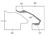
- the mold is opened with the resin molded product C20 left on the cavity B20 side instead of the core A20 side.
- the occurrence of the undercut A11 and the particle line B12 as described above is eliminated by forming the thick portion C21 in the resin molded product C20.
- the actually molded part 1100 has a general thick part 1103 having a relatively small thickness and a thick part 1104 having a relatively large thickness.
- the molding location 1100 has a thickness change / change portion 1105 that changes from the general thickness portion 1103 to the thick portion 1104 so that the thickness increases.
- the thickness t 1 of the general thickness portion 1103 was set to 1.0 mm in consideration of the balance of oil precipitation, moldability, and yield.
- the thickness t 2 of the thick portion 1104 is set to 3.5 mm.
- the width of the thickness removing / changing portion 1105 in the separation direction between the general thick portion 1103 and the thick portion 1104 is set to 40 mm in consideration of the balance between the yield and the oil precipitation suppressing effect.
- a skin-like texture 1112 is formed on the product surface 1111, and fine irregularities 1113 are formed on the surface of the texture 1112.
- the depth of the concave portion included in the fine irregularities 1113 was about 10 ⁇ m.
- fine irregularities 1122 are formed on the back surface opposite to the product surface 1111.
- the fine irregularities 1122 are formed over the portion 1106 adjacent to the thickness change portion 1105, the thickness change portion 1105, and the thick portion 1104 in the general thickness portion 1103.
- the width of the adjacent portion 1106 in the adjacent direction between the general thickness portion 1103 and the thickness change / change portion 1105 was about 30 mm.
- the depth of the concave portion included in the fine irregularities 1122 was about 20 ⁇ m. If this depth is too deep, the fine irregularities 1122 and the mold will bite, and in the worst case, the product surface 1111 side may be dragged to the back surface side when the mold is opened, and the product surface 1111 may be distorted. For example, if it is about 20 micrometers, such a mold release defect can be suppressed.
- fine irregularities 122 may be formed on the second molding surface 121, and such a configuration also suppresses oil precipitation on the product surface side.
- the resin 130 is filled thicker than the general portion 103, and the shrinkage amount of the resin 130 accompanying cooling is larger than that of the general portion 103.
- the biting of the resin 130 against the fine irregularities 122 is alleviated, so that release defects are suppressed.
- the present invention is not limited to injection molding, and can be applied to other resin molding such as press molding.
Landscapes
- Engineering & Computer Science (AREA)
- Mechanical Engineering (AREA)
- Manufacturing & Machinery (AREA)
- Moulds For Moulding Plastics Or The Like (AREA)
Abstract
【課題】艶ムラを抑制可能な成形型および成形方法を提供する。 【解決手段】成形型100は、相対的に近接離間自在な第1の型110および第2の型120を有する。第1の型は、微細な凹凸113が表面に形成されたシボ112を含む第1成形面111を有し、第2の型は、近接した第1成形面との間に空洞101を形作る第2成形面121を有している。第2成形面のうち、第1の型と第2の型とが閉じた状態でシボと対向する少なくとも一部には、微細な凹凸122が形成されている。
Description
本発明は、成形型および成形方法に関する。
従来、インストルメントパネル等の自動車の内装材では、表面にシボを有する樹脂成形品が用いられており、近年では高級感演出への要望が高まっている。高級感をどのように演出するかは様々であり、例えば低グロス化を図ったり、表面の艶ムラを防止したりすることが考えられる。
艶ムラに対する一般的な対策の1つとしては、タッチアップ塗装があるが、タッチアップ塗装の工程追加によってコストが増加するだけでなく、塗装によってシボが埋まってしまうことがある。このため、タッチアップ塗装によっては、シボ本来の機能を生かし切れないという難点がある。
一方で、タッチアップ塗装以外にも、例えば特許文献1~特許文献3のように、樹脂成形品の成形性や表面品質改善を図っている従来技術がある。
しかしながら本発明者らが鋭意検討したところ、艶ムラは、金型内に充填される樹脂の表面に析出するオイルが一因であることが突き止められ、そのような要因を解消するものではない上記従来技術は、無塗装化に繋がるような抜本的な解決策になり難い。
例えば、上記特許文献1は、金型における樹脂の導入部であるフィルムゲートの隙間の大きさを、樹脂の流入方向上流側から下流側にかけて変化させることによって、デフォーム等の成形不良を防止しているが、上述のようなオイル析出に起因した艶ムラに対しては効果がない。また、フィルムゲートの隙間の大きさが変化する部分をある程度長くする必要があるため、駄肉の増加に繋がる。
また、上記特許文献2は、金型内の空洞に射出される樹脂の流れが乱れるのに起因して艶ムラが生じることに着目し、その流れを金型内に設けた格子状の構造によって制御することを開示しているが、オイルの析出という、樹脂の流れとは別の要因によって生じる艶ムラに対しては効果がない。
また、上記特許文献3は、特殊なシリカゲルからなる艶消し剤を、樹脂成形品の原料である樹脂に添加して、あるいは艶消し剤を含む塗料を樹脂成形品の表面にコーティングして、光沢の抑えられた艶の無い仕上がりにすることを開示しているが、艶ムラの発生要因自体を解消する訳ではない。また、艶消し剤自体のコストや、その添加作業またはコーティング作業にともなうコストがかかるとともに、例えば溶剤への引火防止等、安全対策の必要性も生じる。
以上のように、従来技術は、艶ムラに対する抜本的な解決策であるとは言い難いのが現状であった。
そこで、本発明は、本発明者らの鋭意検討の結果得られた新たな知見に基づき、艶ムラを抑制可能な成形型および成形方法を提供することを目的とする。
上記目的を達成するための本発明の成形型は、相対的に近接離間自在な第1の型および第2の型を有する。第1の型は、微細な凹凸が表面に形成されたシボを含む第1成形面を有し、第2の型は、近接した第1成形面との間に空洞を形作る第2成形面を有している。第2成形面のうち、第1の型と第2の型とが閉じた状態でシボと対向する少なくとも一部には、微細な凹凸が形成されている。
上記目的を達成するための本発明の成形方法は、シボが形成された第1成形面を有する第1の型と、シボに対向する微細な凹凸が少なくとも一部に形成された第2成形面を有する第2の型とを近接させて閉じる。また、本発明の成形方法は、第1成形面と第2成形面との間に形成される空洞内に樹脂を射出し、空洞内の樹脂に圧力を加える。そして、本発明の成形方法は、シボの表面に形成されている微細な凹凸に、樹脂を充填する。
以下、添付した図面を参照しながら、本発明の実施形態を説明する。なお、図面の寸法比率は、説明の都合上誇張されており、実際の比率とは異なる。
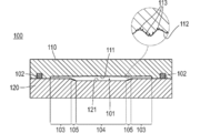
図1に示すように、実施形態の金型100(成形型)は、相対的に近接離間自在な第1の型110および第2の型120を有する。
第1の型110および第2の型120のうちの一方は、例えばシリンダ等の駆動部と接続し金型100の開閉の際に動かされる可動型であり、他方は固定された固定型であるが、これに限定されず、それらの両方を動かして金型100を開閉してもよい。
第1の型110は、シボ112が形成された第1成形面111を有している。シボ112の表面には、微細な凹凸113が形成されている。
第2の型120は、第1成形面111と対向する第2成形面121を有している。第1の型110と第2の型120とは、閉じた状態で第1成形面111と第2成形面121との間に空洞101を形成する。
空洞101は、樹脂を射出するノズル(不図示)と連通する。また、空洞101のまわりには、第1の型110と第2の型120との間に、例えばシリコーン樹脂によって形成されたシール部材102が配置され、空洞101内に射出される樹脂の漏出を防止する。空洞101は、その内部を排気する例えばポンプ等と連通していてもよい。
空洞101には、第1成形面111と第2成形面121との間の隙間が他の一般部分103に比べて広い拡大部104があるとともに、一般部分103から拡大部104へと隙間が広がるように変化している除変部105がある。
一般部分103における隙間は、例えば0.5mm~2.5mmであるが、これに限定されない。拡大部104における隙間は、例えば1.5mm~4.5mmであるが、これに限定されない。一般部分103と拡大部104との離間方向における除変部105の幅は、例えば20mm~160mmであるが、これに限定されない。
図2に示すように、除変部105においては、シボ112に対向して微細な凹凸122が第2成形面121に形成されている。また、一般部分103のうち、除変部105に隣接する箇所106においても、シボ112に対向して微細な凹凸122が第2成形面121に形成されている。
一般部分103と除変部105との隣接方向における隣接箇所106の幅は、例えば30mmであるが、これに限定されない。
微細な凹凸122は、微細な凹凸113に含まれる凹部よりも、深い凹部を含んでいる。微細な凹凸113に含まれる凹部の深さは、例えば、5~30μmである。微細な凹凸122に含まれる凹部の深さは、例えば、微細な凹凸113に含まれる凹部の深さ以上60μm以下であり、好ましくは、微細な凹凸113に含まれる凹部の深さの2倍程度である。
次に、本実施形態の成形方法を述べる。
図3に示すように、本実施形態の成形方法は、型締め工程S1、射出工程S2、保圧工程S3、冷却工程S4、および脱型工程S5を有する。
型締め工程S1では、第1の型110と第2の型120とが近接して閉じられ、その状態を保持される。
射出工程S2では、空洞101内に樹脂が射出される。このとき、樹脂は高速で流し込まれので、金型100の破損防止のため、空洞101の全体積に対して例えば90~95%程度の割合で樹脂は充填される。
保圧工程S3では、空洞101内の樹脂に圧力が加えられる。
冷却工程S4では、空洞101内の樹脂が冷却されて硬化する。樹脂の冷却は、例えば、金型100の内部に設けられた循環経路に冷却水等の冷却媒体を流して行われる。
空洞101内の樹脂が硬化した後、脱型工程S5では、第1の型110と第2の型120とが離間して金型100が開けられ、樹脂成形品が取り出される。
次に、本実施形態と異なる比較例について述べる。
図4に示すように、比較例では、上記実施形態と異なる金型100Aを用いて、上記実施形態と同様の工程で射出成形が行われる。
射出される樹脂130は、上記実施形態と比較例とで同様であり、ゴム131、およびオイル132を含む。樹脂130は、例えば20%以上のオイル132を含むが、これに限定されない。また、樹脂130は、それら以外にも、例えばタルク等の他の添加物を含んでもよい。
樹脂130は、例えば、ポリプロピレン(PP)、ポリアミド(PA)、ポリカーボネート(PC)、ポリエチレン(PE)、ポリスチレン(PS)、アクリロニトリル-ブタジエン-スチレンプラスチック(ABS)、エラストマー(ゴム)等の熱可塑性樹脂である。樹脂130は、加熱されて流動性を有する状態で射出され、例えば金型100や金型100Aに備えられるヒータからの熱によって流動性を保ったまま充填される。
ゴム131は、完成した樹脂成形品において所望の質感が出るように加えられている。オイル132は、例えば、樹脂130の流動性を上げたり、完成した樹脂成形品の離型性を高めたりするために加えられている。
上記実施形態と比較例とで第1の型110は共通しているが、比較例の金型100Aは、上記実施形態と異なる第2の型120Aを有する。第2の型120Aでは、上記実施形態の微細な凹凸122がなく、平滑な第2成形面121Aが形成されている点で、上記実施形態と異なるが、他の構成は上記実施形態の第2の型120と同様である。
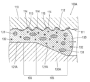
射出工程S2で樹脂130が射出されると、平滑な第2成形面121Aでは、ほぼ隙間のないスキン層が形成される。一方、第1成形面111では、微細な凹凸113までは樹脂130が完全に充填されず、樹脂130と第1の型110との間に隙間114が形成される。
本来、その後の保圧工程S3および冷却工程S4を経た後には、隙間114にも樹脂130が充填されているはずであるが、本発明者らが実際に実験したところ、隙間114に樹脂130が充填されず、シボ112の形状や微細な凹凸113の形状が転写されないことがあった。特に、除変部105およびそれに隣接する箇所106において、そのような事象が顕著であった。
これは、図5に示すように、オイル132が樹脂130の表面に析出し、シボ112や微細な凹凸113との間に介在するためであり、樹脂130の圧力差が生じ易い除変部105、およびそれに隣接する箇所106において、オイル132の析出が特に顕著になるためであると考えられる。
その検証のため、本発明者らは、比較例の金型100Aを実際に作製するとともに、4つの異なる測定位置123、124、125、126において、射出工程S2から冷却工程S4までの実際の圧力変化を測定した。
測定位置123では、除変部105から離間した一般部分103についての圧力変化が測定される。測定位置124では、除変部105に隣接する箇所106についての圧力変化が測定される。測定位置125では、除変部105についての圧力変化が測定される。測定位置126では、拡大部104についての圧力変化が測定される。
図6に示すように、射出工程S2では、測定位置123~126で圧力差はあまり生じなかったが、保圧工程S3および冷却工程S4を経るうちに、それらの圧力差が大きくなっていった。
特に、圧力低下が比較的緩やかである測定位置123、124に対し、測定位置125、126では圧力が急激に低下し、測定位置123、124と、測定位置125、126との間で圧力差が大きく生じた。すなわち、一般部分103および隣接箇所106に対する、除変部105および拡大部104の圧力差が大きい。このような圧力差が、除変部105でオイル132が特に析出し易い要因であると考えられる。
脱型工程S5後に、実際に第1成形面111に付着した成分の分析を行ったところ、圧力差の生じ易い除変部105では、他の部分に比べて最もオイル132が析出していた。また、その隣接箇所106でも、オイル132が多く析出した。
樹脂130の圧力差は、冷却にともなう収縮量の違いに起因して生じ、相対的に薄肉で熱量の小さい一般部分103の樹脂130に比べ、相対的に厚肉で熱量の大きい除変部105および拡大部104の樹脂130では、冷却にともなう収縮量が大きくなる。この影響が隣接箇所106に及ぶため、隣接箇所106でも圧力差が大きくなり、それにともなってオイル132の析出量が多くなると考えられる。
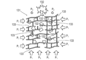
図7に示すように、ゴム131に対し樹脂130から加わる圧力P1が均一で、圧力差の無い場合、ゴム131を構成している分子鎖133の間に入り込んでいるオイル132は、圧力P1で全体から均一に押圧されて、ゴム131の内部に留まる。
一方、図8に示すように、圧力差(P1>P2)があると、オイル132が、相対的に小さい圧力P2のかかっている箇所からゴム131の外部へと出ていき、その結果、不均一な圧力状態が生じている樹脂130では部分的にオイル132が多くなるため、それにともないオイル132の析出量も多くなると考えられる。
実際、図9に示すように、均一な圧力状態ではオイル132の析出があまり確認できなかったのに対し、図10に示すように、不均一な圧力状態ではオイル132の析出が多く確認された。
次に、本実施形態の作用効果を述べる。
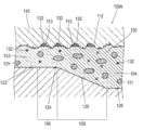
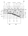
図11に示すように、本実施形態では、微細な凹凸113の形成されているシボ112に対向して、微細な凹凸122が形成されており、微細な凹凸122の側にオイル132を析出させるようにしている。
このため、シボ112や微細な凹凸113の側にオイル132が析出し難くなり、それらに樹脂130が確実に充填される。その結果、シボ112や微細な凹凸113の形状がしっかりと転写されて形作られる。
これと異なり、図12に示すように、上述の比較例で作製された樹脂成形品140Aでは、シボ112や微細な凹凸113の転写がオイル132によって妨げられて、比較的なだらかな箇所141Aが製品面に部分的に形成される。このため、製品面に光L1が当たった際、微細な凹凸113のあるシボ112では、乱反射L2が生じるのに対し、乱反射L2を主として生じさせる微細な凹凸113のない、比較的なだらかな箇所141Aでは、面反射のような反射L3が生じる。その結果、それらの反射の違いが艶ムラとして視認される。
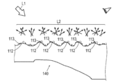
一方、図13に示すように本実施形態の樹脂成形品140では、微細な凹凸113のあるシボ112が、オイル132の析出によって妨げられることなく確実に形作られるため、光L1が当たると製品面の全体で乱反射L2が生じる。従って、艶ムラを抑制できる。
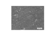
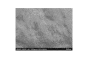
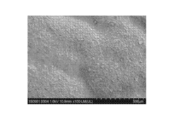
実際、図14に示すように、比較例によれば、微細な凹凸のない比較的なだらかな面が形成され、これが艶ムラの要因となるのに対し、図15に示すように、本実施形態によれば、微細な凹凸がシボ面の全体に形成されて艶ムラが抑制される。
本実施形態では、樹脂130の圧力差が生じ易くオイル132が析出し易い除変部105において、微細な凹凸122が形成されており、シボ112や微細な凹凸113がある側へのオイル132の析出が特に効果的に抑制される。その結果、シボ112や微細な凹凸113がより確実に転写されるため、艶ムラ防止効果を一層高めることができる。
また、除変部105では、一般部分103に比べて樹脂130が厚肉に充填され、冷却にともなう樹脂130の収縮量が一般部分103に比べて大きくなる。その結果、微細な凹凸122に対する樹脂130の食いつきが緩和されるため、離型不良が抑制される。
本実施形態では、除変部105に次いでオイル132が析出し易い隣接箇所106に微細な凹凸122が形成されており、これによって、シボ112や微細な凹凸113がある側へのオイル132の析出が効果的に抑制される。その結果、シボ112や微細な凹凸113がより確実に転写されるため、艶ムラ防止効果をより一層高めることができる。
微細な凹凸122は、第2成形面121において、除変部105やその隣接箇所106以外の他の場所にも設けられてもよい。しかしながら、本実施形態のようにオイル132が特に析出し易い箇所に範囲を限定して設けることによって、効果的にオイル132の析出を抑制しつつ、第2成形面121への微細な凹凸122の加工費を抑えることができる。
微細な凹凸122は、微細な凹凸113に含まれる凹部よりも深い凹部を含んでおり、オイル132が溜り易い。このため、微細な凹凸122へのオイル132の析出量を増やすことによって、シボ112や微細な凹凸113側へのオイル132の析出をより効果的に抑制できる。
<実施例>
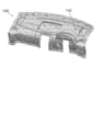
図16に示すように、本発明者らは、インストルメントパネル用の表皮材1000を実施例として成形した。
図16に示すように、本発明者らは、インストルメントパネル用の表皮材1000を実施例として成形した。
表皮材1000の形成材料は、ポリプロピレン(PP)であり、ゴムおよびオイルを20%以上含む。本発明者らは、表皮材1000のうち、艶ムラが生じ易い箇所1100が上記実施形態に準じた構成となるよう、金型を設計した。
使用可能な金型としては、横型または縦型のものがあるが、本発明者らは、大きな成形品を扱い易い横型のものを用いて成形を行った。
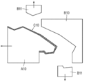
また、金型は、一般的に2分割構造を有し、可動型であるコア、および固定型であるキャビティを有するが、金型からの樹脂成形品の取出し方の違いによって、2つの形態に分類される。
図17および図18に示すように、一方の形態によれば、キャビティB10側ではなく、コアA10側に樹脂成形品C10を残した状態で金型が開けられる。このようなコア残しの取出し方では、アンダーカットA11の処理のために、スライド構造B11が用いられるが、その結果、パーティクルラインB12が製品面に転写されてしまう。
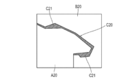
これと異なり、図19および図20に示すように、もう一方の形態によれば、コアA20側ではなく、キャビティB20側に樹脂成形品C20を残した状態で金型が開けられる。このようなキャビ残しの取出し方では、樹脂成形品C20に厚肉部C21を形成することによって、前述のようなアンダーカットA11、ひいてはパーティクルラインB12の発生が解消される。
また、樹脂成形品がキャビティB20側に残るため、製品面に形成されたシボが型開きの際にむしられるシボカジリと称される現象が生じないという利点もある。それらの利点から、本発明者らは、キャビ残しの形態で型開きされる金型を用いて成形を行ったが、本発明はこれに限定されない。
キャビティB20側に残った樹脂成形品C20をそこから脱型させる際、コア残しの形態で用いられるようなエジェクターを製品面に適用することはできないが、例えば特許第5897714号明細書で開示された技術を応用して脱型することが可能である。
図21に示すように、実際に成形された成形箇所1100は、肉厚の相対的に小さい一般肉厚部1103、および肉厚の相対的に大きい厚肉部1104を有する。また、成形箇所1100は、一般肉厚部1103から厚肉部1104へと肉厚が大きくなるように変化している肉厚除変部1105を有している。
一般肉厚部1103の肉厚t1は、オイルの析出、成形性、および歩留りのバランスを考慮して、1.0mmとした。また、同様の理由で、厚肉部1104の肉厚t2は3.5mmとした。一般肉厚部1103と厚肉部1104との離間方向における肉厚除変部1105の幅は、歩留り、およびオイルの析出抑制効果のバランスを考慮し、40mmとした。
皮シボ状のシボ1112が製品面1111に形成されており、また、シボ1112の表面に微細な凹凸1113が形成されている。微細な凹凸1113に含まれる凹部の深さは、10μm程度とした。
一方、製品面1111と反対側の裏面には、微細な凹凸1122が形成されている。微細な凹凸1122は、一般肉厚部1103のうちの肉厚除変部1105に隣接する箇所1106、肉厚除変部1105、および厚肉部1104にわたって形成されている。一般肉厚部1103と肉厚除変部1105との隣接方向における隣接箇所1106の幅は、約30mmとした。
また、微細な凹凸1122に含まれる凹部の深さは、20μm程度とした。この深さが深すぎると、微細な凹凸1122と金型とが食いつき、最悪の場合、型開きの際に製品面1111側が裏面側に引きずられて製品面1111に歪みが発生する虞があるが、例えば20μm程度であれば、そのような離型不良を抑制できる。
以上のような構成で成形箇所1100を成形したところ、実際に艶ムラが抑制された。また、微細な凹凸1122では、狙い通りオイルが析出し、裏面に微細な凹凸1122を形成することによって、製品面1111側へのオイルの析出が抑制されることが確認できた。
本発明は、上述した実施形態に限定されるものではなく、特許請求の範囲内で種々改変できる。
例えば、上記実施形態の拡大部104において、第2成形面121に微細な凹凸122を形成してもよく、このような構成によっても、製品面側へのオイルの析出が抑制される。また、拡大部104では、一般部分103に比べて樹脂130が厚肉に充填され、冷却にともなう樹脂130の収縮量が一般部分103に比べて大きくなる。その結果、微細な凹凸122に対する樹脂130の食いつきが緩和されるため、離型不良が抑制される。
また、本発明は、射出成形に限定されず、例えばプレス成形等の他の樹脂成形に適用可能である。
本出願は、2017年5月25日に出願された日本特許出願番号2017-103955号に基づいており、その開示内容は、参照により全体として引用されている。
100 金型(成形型)、
100A 比較例の金型、
101 空洞、
102 シール部材、
110 第1の型、
111 第1成形面、
112 シボ、
113 シボの表面に形成された微細な凹凸、
114 隙間、
120 第2の型、
120A 比較例の第2の型、
121 第2成形面、
121A 比較例の第2成形面、
122 第2成形面に形成された微細な凹凸、
123、124、125、126 圧力変化の測定位置、
130 樹脂、
131 ゴム、
132 オイル、
133 分子鎖、
140 樹脂成形品、
140A 比較例の樹脂成形品、
141A なだらかな面、
1000 樹脂成形品の実施例、
1100 微細な凹凸が裏面に形成された箇所、
1103 一般肉厚部、
1104 厚肉部、
1105 肉厚除変部、
1106 肉厚除変部に隣接する箇所、
1111 製品面、
1112 シボ、
1113 シボの表面に形成された微細な凹凸、
1122 樹脂成形品の裏面に形成された微細な凹凸。
100A 比較例の金型、
101 空洞、
102 シール部材、
110 第1の型、
111 第1成形面、
112 シボ、
113 シボの表面に形成された微細な凹凸、
114 隙間、
120 第2の型、
120A 比較例の第2の型、
121 第2成形面、
121A 比較例の第2成形面、
122 第2成形面に形成された微細な凹凸、
123、124、125、126 圧力変化の測定位置、
130 樹脂、
131 ゴム、
132 オイル、
133 分子鎖、
140 樹脂成形品、
140A 比較例の樹脂成形品、
141A なだらかな面、
1000 樹脂成形品の実施例、
1100 微細な凹凸が裏面に形成された箇所、
1103 一般肉厚部、
1104 厚肉部、
1105 肉厚除変部、
1106 肉厚除変部に隣接する箇所、
1111 製品面、
1112 シボ、
1113 シボの表面に形成された微細な凹凸、
1122 樹脂成形品の裏面に形成された微細な凹凸。
Claims (6)
- 相対的に近接離間自在な第1の型および第2の型を有する成形型であって、
微細な凹凸が表面に形成されたシボを含む第1成形面を、前記第1の型が有するとともに、
近接した前記第1成形面との間に空洞を形作る第2成形面を、前記第2の型が有しており、
前記第2成形面のうち、前記第1の型と前記第2の型とが閉じた状態で前記シボと対向する少なくとも一部に、微細な凹凸が形成されている、成形型。 - 前記空洞には、前記第1成形面と前記第2成形面との間の隙間が他の一般部分に比べて広い拡大部があるとともに、前記一般部分から前記拡大部へと前記隙間が広がるように変化している除変部があり、
当該除変部において、前記第2成形面に前記微細な凹凸が形成されている、請求項1に記載の成形型。 - 前記空洞には、前記第1成形面と前記第2成形面との間の隙間が他の一般部分に比べて広い拡大部があるとともに、前記一般部分から前記拡大部へと前記隙間が広がるように変化している除変部があり、
前記一般部分のうち前記除変部に隣接する箇所において、前記第2成形面に前記微細な凹凸が形成されている、請求項1または請求項2に記載の成形型。 - 前記空洞には、前記第1成形面と前記第2成形面との間の隙間が他の一般部分に比べて広い拡大部があり、
当該拡大部において、前記第2成形面に前記微細な凹凸が形成されている、請求項1~請求項3のうちのいずれか1つに記載の成形型。 - 前記第2成形面の微細な凹凸は、前記シボの表面の微細な凹凸に含まれる凹部よりも、深い凹部を含んでいる、請求項1~請求項4のうちのいずれか1つに記載の成形型。
- シボが形成された第1成形面を有する第1の型と、前記シボに対向する微細な凹凸が少なくとも一部に形成された第2成形面を有する第2の型とを近接させて閉じ、
前記第1成形面と前記第2成形面との間に形成される空洞内に樹脂を射出し、
前記空洞内の樹脂に圧力を加え、
前記シボの表面に形成されている微細な凹凸に、前記樹脂を充填する、成形方法。
Applications Claiming Priority (2)
| Application Number | Priority Date | Filing Date | Title |
|---|---|---|---|
| JP2017-103955 | 2017-05-25 | ||
| JP2017103955A JP2020121409A (ja) | 2017-05-25 | 2017-05-25 | 成形型および成形方法 |
Publications (1)
| Publication Number | Publication Date |
|---|---|
| WO2018216367A1 true WO2018216367A1 (ja) | 2018-11-29 |
Family
ID=64396750
Family Applications (1)
| Application Number | Title | Priority Date | Filing Date |
|---|---|---|---|
| PCT/JP2018/014760 Ceased WO2018216367A1 (ja) | 2017-05-25 | 2018-04-06 | 成形型および成形方法 |
Country Status (2)
| Country | Link |
|---|---|
| JP (1) | JP2020121409A (ja) |
| WO (1) | WO2018216367A1 (ja) |
Cited By (1)
| Publication number | Priority date | Publication date | Assignee | Title |
|---|---|---|---|---|
| CN116249608A (zh) * | 2021-03-09 | 2023-06-09 | 株式会社Lg化学 | 注塑模具 |
Families Citing this family (1)
| Publication number | Priority date | Publication date | Assignee | Title |
|---|---|---|---|---|
| JP7643245B2 (ja) * | 2021-08-03 | 2025-03-11 | 日産自動車株式会社 | 射出成形方法及び射出成型用型 |
Citations (3)
| Publication number | Priority date | Publication date | Assignee | Title |
|---|---|---|---|---|
| JP2014043047A (ja) * | 2012-08-27 | 2014-03-13 | Mazda Motor Corp | シボ付き樹脂成形品 |
| JP2016087917A (ja) * | 2014-11-04 | 2016-05-23 | カルソニックカンセイ株式会社 | 樹脂成形品構造および樹脂成形用金型 |
| JP2017024290A (ja) * | 2015-07-23 | 2017-02-02 | トヨタ車体株式会社 | 成形品及び成形品の製造方法 |
-
2017
- 2017-05-25 JP JP2017103955A patent/JP2020121409A/ja active Pending
-
2018
- 2018-04-06 WO PCT/JP2018/014760 patent/WO2018216367A1/ja not_active Ceased
Patent Citations (3)
| Publication number | Priority date | Publication date | Assignee | Title |
|---|---|---|---|---|
| JP2014043047A (ja) * | 2012-08-27 | 2014-03-13 | Mazda Motor Corp | シボ付き樹脂成形品 |
| JP2016087917A (ja) * | 2014-11-04 | 2016-05-23 | カルソニックカンセイ株式会社 | 樹脂成形品構造および樹脂成形用金型 |
| JP2017024290A (ja) * | 2015-07-23 | 2017-02-02 | トヨタ車体株式会社 | 成形品及び成形品の製造方法 |
Cited By (3)
| Publication number | Priority date | Publication date | Assignee | Title |
|---|---|---|---|---|
| CN116249608A (zh) * | 2021-03-09 | 2023-06-09 | 株式会社Lg化学 | 注塑模具 |
| EP4186675A4 (en) * | 2021-03-09 | 2024-03-13 | Lg Chem, Ltd. | INJECTION MOLD |
| US12472669B2 (en) | 2021-03-09 | 2025-11-18 | Lg Chem, Ltd. | Injection mold |
Also Published As
| Publication number | Publication date |
|---|---|
| JP2020121409A (ja) | 2020-08-13 |
Similar Documents
| Publication | Publication Date | Title |
|---|---|---|
| US7862758B2 (en) | In-mold coat-forming method | |
| WO2018216367A1 (ja) | 成形型および成形方法 | |
| KR101618362B1 (ko) | 사출압축성형이 적용된 필름인서트성형 장치 및 그 방법 | |
| JP2015178273A (ja) | 樹脂材料の射出成形方法 | |
| RU2629071C2 (ru) | Система подведения расплава с пленочным литником для способов декорирования в пресс-форме или этикетирования в пресс-форме при литье под давлением | |
| RU2344039C2 (ru) | Способ литья под давлением и машина для литья под давлением | |
| WO2010106968A1 (ja) | 型内塗装品形成金型 | |
| JP4614812B2 (ja) | 型内被覆成形装置及び型内被覆成形方法 | |
| JP5557106B2 (ja) | 金型内塗装用金型及び金型内塗装方法 | |
| JPWO2008120729A1 (ja) | 型内被覆成形用金型 | |
| JP6071804B2 (ja) | 射出成形金型 | |
| US7479244B2 (en) | Process for the production of plates made of transparent plastic material with non-transparent areas | |
| JP4407810B2 (ja) | 型内被覆成形用金型 | |
| JP4716421B2 (ja) | 合成樹脂製灯具構成部材の表面被膜形成方法および合成樹脂製灯具構成部材 | |
| JP4296595B2 (ja) | 型内被覆成形方法及び型内被覆成形用金型 | |
| JP5093744B2 (ja) | 型内被覆成形用金型 | |
| JP2007253494A (ja) | 型内被覆成形方法、型内被覆成形装置及び型内被覆成形品 | |
| JP2012071432A (ja) | 金型内塗装用金型及び金型内塗装方法 | |
| JP2001315169A (ja) | 射出成形品の製造方法および射出成形型 | |
| JP4884690B2 (ja) | 型内被覆成形用金型及び型内被覆成形方法 | |
| JP5286656B2 (ja) | 型内被覆成形用金型 | |
| KR101551296B1 (ko) | 박판 성형용 사출압축금형 | |
| JP2011042133A (ja) | 板状成形品の型締力増幅機構付金型 | |
| JP2015182400A (ja) | 射出成形用金型及びそれを用いた樹脂成形品の製造方法 | |
| JP4452672B2 (ja) | 射出成形中に樹脂がキャビティ面から剥離しやすい箇所を予測する方法とそれを利用した射出成形型と射出成形方法 |
Legal Events
| Date | Code | Title | Description |
|---|---|---|---|
| 121 | Ep: the epo has been informed by wipo that ep was designated in this application |
Ref document number: 18805307 Country of ref document: EP Kind code of ref document: A1 |
|
| NENP | Non-entry into the national phase |
Ref country code: DE |
|
| 122 | Ep: pct application non-entry in european phase |
Ref document number: 18805307 Country of ref document: EP Kind code of ref document: A1 |
|
| NENP | Non-entry into the national phase |
Ref country code: JP |