WO2018211754A1 - Dispositif d'amortissement de vibrations - Google Patents
Dispositif d'amortissement de vibrations Download PDFInfo
- Publication number
- WO2018211754A1 WO2018211754A1 PCT/JP2018/004388 JP2018004388W WO2018211754A1 WO 2018211754 A1 WO2018211754 A1 WO 2018211754A1 JP 2018004388 W JP2018004388 W JP 2018004388W WO 2018211754 A1 WO2018211754 A1 WO 2018211754A1
- Authority
- WO
- WIPO (PCT)
- Prior art keywords
- pores
- liquid
- liquid chamber
- chamber
- radial direction
- Prior art date
Links
Images


Classifications
-
- F—MECHANICAL ENGINEERING; LIGHTING; HEATING; WEAPONS; BLASTING
- F16—ENGINEERING ELEMENTS AND UNITS; GENERAL MEASURES FOR PRODUCING AND MAINTAINING EFFECTIVE FUNCTIONING OF MACHINES OR INSTALLATIONS; THERMAL INSULATION IN GENERAL
- F16F—SPRINGS; SHOCK-ABSORBERS; MEANS FOR DAMPING VIBRATION
- F16F13/00—Units comprising springs of the non-fluid type as well as vibration-dampers, shock-absorbers, or fluid springs
- F16F13/04—Units comprising springs of the non-fluid type as well as vibration-dampers, shock-absorbers, or fluid springs comprising both a plastics spring and a damper, e.g. a friction damper
- F16F13/06—Units comprising springs of the non-fluid type as well as vibration-dampers, shock-absorbers, or fluid springs comprising both a plastics spring and a damper, e.g. a friction damper the damper being a fluid damper, e.g. the plastics spring not forming a part of the wall of the fluid chamber of the damper
- F16F13/08—Units comprising springs of the non-fluid type as well as vibration-dampers, shock-absorbers, or fluid springs comprising both a plastics spring and a damper, e.g. a friction damper the damper being a fluid damper, e.g. the plastics spring not forming a part of the wall of the fluid chamber of the damper the plastics spring forming at least a part of the wall of the fluid chamber of the damper
- F16F13/10—Units comprising springs of the non-fluid type as well as vibration-dampers, shock-absorbers, or fluid springs comprising both a plastics spring and a damper, e.g. a friction damper the damper being a fluid damper, e.g. the plastics spring not forming a part of the wall of the fluid chamber of the damper the plastics spring forming at least a part of the wall of the fluid chamber of the damper the wall being at least in part formed by a flexible membrane or the like
- F16F13/105—Units comprising springs of the non-fluid type as well as vibration-dampers, shock-absorbers, or fluid springs comprising both a plastics spring and a damper, e.g. a friction damper the damper being a fluid damper, e.g. the plastics spring not forming a part of the wall of the fluid chamber of the damper the plastics spring forming at least a part of the wall of the fluid chamber of the damper the wall being at least in part formed by a flexible membrane or the like characterised by features of partitions between two working chambers
- F16F13/107—Passage design between working chambers
-
- B—PERFORMING OPERATIONS; TRANSPORTING
- B60—VEHICLES IN GENERAL
- B60K—ARRANGEMENT OR MOUNTING OF PROPULSION UNITS OR OF TRANSMISSIONS IN VEHICLES; ARRANGEMENT OR MOUNTING OF PLURAL DIVERSE PRIME-MOVERS IN VEHICLES; AUXILIARY DRIVES FOR VEHICLES; INSTRUMENTATION OR DASHBOARDS FOR VEHICLES; ARRANGEMENTS IN CONNECTION WITH COOLING, AIR INTAKE, GAS EXHAUST OR FUEL SUPPLY OF PROPULSION UNITS IN VEHICLES
- B60K5/00—Arrangement or mounting of internal-combustion or jet-propulsion units
- B60K5/12—Arrangement of engine supports
- B60K5/1208—Resilient supports
-
- F—MECHANICAL ENGINEERING; LIGHTING; HEATING; WEAPONS; BLASTING
- F16—ENGINEERING ELEMENTS AND UNITS; GENERAL MEASURES FOR PRODUCING AND MAINTAINING EFFECTIVE FUNCTIONING OF MACHINES OR INSTALLATIONS; THERMAL INSULATION IN GENERAL
- F16F—SPRINGS; SHOCK-ABSORBERS; MEANS FOR DAMPING VIBRATION
- F16F13/00—Units comprising springs of the non-fluid type as well as vibration-dampers, shock-absorbers, or fluid springs
- F16F13/04—Units comprising springs of the non-fluid type as well as vibration-dampers, shock-absorbers, or fluid springs comprising both a plastics spring and a damper, e.g. a friction damper
- F16F13/06—Units comprising springs of the non-fluid type as well as vibration-dampers, shock-absorbers, or fluid springs comprising both a plastics spring and a damper, e.g. a friction damper the damper being a fluid damper, e.g. the plastics spring not forming a part of the wall of the fluid chamber of the damper
- F16F13/08—Units comprising springs of the non-fluid type as well as vibration-dampers, shock-absorbers, or fluid springs comprising both a plastics spring and a damper, e.g. a friction damper the damper being a fluid damper, e.g. the plastics spring not forming a part of the wall of the fluid chamber of the damper the plastics spring forming at least a part of the wall of the fluid chamber of the damper
- F16F13/10—Units comprising springs of the non-fluid type as well as vibration-dampers, shock-absorbers, or fluid springs comprising both a plastics spring and a damper, e.g. a friction damper the damper being a fluid damper, e.g. the plastics spring not forming a part of the wall of the fluid chamber of the damper the plastics spring forming at least a part of the wall of the fluid chamber of the damper the wall being at least in part formed by a flexible membrane or the like
-
- F—MECHANICAL ENGINEERING; LIGHTING; HEATING; WEAPONS; BLASTING
- F16—ENGINEERING ELEMENTS AND UNITS; GENERAL MEASURES FOR PRODUCING AND MAINTAINING EFFECTIVE FUNCTIONING OF MACHINES OR INSTALLATIONS; THERMAL INSULATION IN GENERAL
- F16F—SPRINGS; SHOCK-ABSORBERS; MEANS FOR DAMPING VIBRATION
- F16F2224/00—Materials; Material properties
- F16F2224/04—Fluids
-
- F—MECHANICAL ENGINEERING; LIGHTING; HEATING; WEAPONS; BLASTING
- F16—ENGINEERING ELEMENTS AND UNITS; GENERAL MEASURES FOR PRODUCING AND MAINTAINING EFFECTIVE FUNCTIONING OF MACHINES OR INSTALLATIONS; THERMAL INSULATION IN GENERAL
- F16F—SPRINGS; SHOCK-ABSORBERS; MEANS FOR DAMPING VIBRATION
- F16F2230/00—Purpose; Design features
- F16F2230/30—Sealing arrangements
-
- F—MECHANICAL ENGINEERING; LIGHTING; HEATING; WEAPONS; BLASTING
- F16—ENGINEERING ELEMENTS AND UNITS; GENERAL MEASURES FOR PRODUCING AND MAINTAINING EFFECTIVE FUNCTIONING OF MACHINES OR INSTALLATIONS; THERMAL INSULATION IN GENERAL
- F16F—SPRINGS; SHOCK-ABSORBERS; MEANS FOR DAMPING VIBRATION
- F16F2230/00—Purpose; Design features
- F16F2230/36—Holes, slots or the like
Definitions
- the present invention relates to a vibration isolator that is applied to, for example, automobiles and industrial machines and absorbs and attenuates vibrations of a vibration generating unit such as an engine.
- a cylindrical first attachment member connected to one of the vibration generating portion and the vibration receiving portion, a second attachment member connected to the other, and both of these attachments
- a configuration includes an elastic body that couples members, and a partition member that partitions a liquid chamber in a first mounting member in which a liquid is sealed into a main liquid chamber and a sub liquid chamber.
- the partition member is formed with a restriction passage that communicates the main liquid chamber and the sub liquid chamber.
- this vibration isolator for example, a large load (vibration) is input from the unevenness of the road surface, etc., and the load is input in the reverse direction due to the rebound of the elastic body after the fluid pressure in the main fluid chamber suddenly increases.
- the main liquid chamber is suddenly depressurized. Then, cavitation in which a large number of bubbles are generated in the liquid due to this sudden negative pressure is generated, and abnormal noise may be generated due to cavitation collapse in which the generated bubbles collapse. Therefore, for example, by providing a valve body in the restriction passage as in the vibration isolator shown in Patent Document 1 below, the main liquid chamber can be negatively pressured even when large amplitude vibration is input. Suppressing configurations are known.
- the conventional vibration isolator has a problem that the structure is complicated by providing the valve body, and tuning of the valve body is required, which increases the manufacturing cost. Further, the provision of the valve body reduces the degree of freedom in design, and as a result, the vibration isolation characteristics may be reduced.
- the present invention has been made in view of the above circumstances, and an object thereof is to provide a vibration isolator capable of suppressing the occurrence of abnormal noise due to cavitation collapse without reducing the vibration isolation characteristics with a simple structure. To do.
- a vibration isolator includes a cylindrical first mounting member coupled to one of a vibration generating unit and a vibration receiving unit, a second mounting member coupled to the other, and both the mounting members.
- An elastic body that elastically connects the liquid chamber, and a partition member that divides the liquid chamber in the first mounting member in which the liquid is sealed into a first liquid chamber and a second liquid chamber, and the partition member
- a liquid-filled vibration isolator having a restriction passage communicating the first liquid chamber and the second liquid chamber, wherein the restriction passage opens to the first liquid chamber.
- a second communication part that opens to the second liquid chamber, and a main body channel that communicates the first communication part and the second communication part, and includes the first communication part and the second communication part.
- At least one has a plurality of pores, and in the main body flow path, the first communication part and the second communication part In a connection portion with at least one of the parts, a swirling flow of liquid is formed according to the flow velocity of the liquid from the other side of the first communication part and the second communication part, and the liquid is A vortex chamber that flows out through the plurality of pores is disposed, and the barrier in which the plurality of pores are formed extends in a direction intersecting a vortex axis along a central axis of the vortex chamber, Among these, in the plan view of the barrier, the flow resistance of the pores located inside the swirl radial direction intersecting the vortex axis is lower than the flow resistance of the pores located outside the swirl radial direction.
- the vibration isolator 10 includes a cylindrical first attachment member 11 connected to one of the vibration generating unit and the vibration receiving unit, and one of the vibration generating unit and the vibration receiving unit.
- the second mounting member 12 to be connected, the elastic body 13 that elastically connects the first mounting member 11 and the second mounting member 12 to each other, and the main liquid chamber (first liquid chamber) to be described later in the first mounting member 11 ) 14 and a partition member 16 that divides into a secondary liquid chamber (second liquid chamber) 15.
- the direction along the central axis O1 of the first mounting member 11 is referred to as the axial direction.
- the second mounting member 12 side along the axial direction is referred to as an upper side
- the partition member 16 side is referred to as a lower side.
- a direction orthogonal to the central axis O1 is referred to as a radial direction
- a direction around the central axis O1 is referred to as a circumferential direction.
- the first mounting member 11, the second mounting member 12, and the elastic body 13 are each formed in a circular shape or an annular shape in a plan view, and are arranged coaxially with the central axis O1.
- the second mounting member 12 is connected to an engine as a vibration generating unit, and the first mounting member 11 is connected to a vehicle body as a vibration receiving unit. This suppresses transmission of engine vibration to the vehicle body.
- the second mounting member 12 is a columnar member extending in the axial direction, and is formed in a hemispherical shape whose lower end bulges downward, and a flange 12a above the lower end of the hemispherical shape. have.
- a screw hole 12b extending downward from the upper end surface of the second mounting member 12 is formed, and a bolt (not shown) serving as an engine-side mounting tool is screwed into the screw hole 12b.
- the second mounting member 12 is disposed in the upper end opening of the first mounting member 11 via the elastic body 13.
- the elastic body 13 is a rubber body that is vulcanized and bonded to the upper end opening of the first mounting member 11 and the outer peripheral surface of the lower portion of the second mounting member 12, respectively, and interposed between them.
- the upper end opening of the mounting member 11 is closed from above.
- the elastic body 13 is sufficiently in close contact with the second mounting member 12 by the upper end of the elastic body 13 coming into contact with the flange portion 12a of the second mounting member 12, and follows better due to the displacement of the second mounting member 12.
- a rubber film 17 is integrally formed on the lower end portion of the elastic body 13 to liquid-tightly cover the inner peripheral surface of the first mounting member 11 and the inner peripheral portion of the lower end opening edge.
- an elastic body made of synthetic resin or the like can be used in addition to rubber.
- the first mounting member 11 is formed in a cylindrical shape having a flange 18 at a lower end portion, and is connected to a vehicle body or the like as a vibration receiving portion via the flange 18. A portion of the inside of the first attachment member 11 located below the elastic body 13 is a liquid chamber 19.
- a partition member 16 is provided at the lower end portion of the first attachment member 11, and a diaphragm 20 is further provided below the partition member 16.
- the partition member 16 is a member formed of metal or resin.
- the partition member 16 includes a disk-shaped partition plate 35 extending in the radial direction, and an annular plate-shaped outer periphery that is connected to the outer peripheral edge of the lower surface of the partition plate 35 and projects radially outward from the partition plate 35. Part 22.
- the outer peripheral surface of the partition plate 35 extends in both the axial direction and the circumferential direction, and is in liquid-tight contact with the inner peripheral surface of the cylindrical rubber film 17.
- the upper surface of the outer peripheral portion 22 is in contact with the lower end opening edge of the first mounting member 11.
- the diaphragm 20 is made of an elastic material such as rubber or soft resin, and is formed in a bottomed cylindrical shape. In a state in which a part of the upper end portion of the diaphragm 20 is fluid-tightly engaged with an annular mounting groove 16 a formed on the lower surface of the outer peripheral portion 22 of the partition member 16, the upper end portion of the diaphragm 20 is connected to the outer peripheral portion 22. It is sandwiched in the axial direction by the lower surface and the ring-shaped holder 21 positioned below the partition member 16.
- the outer peripheral portion 22 of the partition member 16 and the holder 21 are arranged in this order on the lower end opening edge of the first mounting member 11 in this order downward, and are fixed integrally with the screw 23.
- the diaphragm 20 is attached to the lower end opening of the first attachment member 11 via the partition member 16.
- the bottom portion of the diaphragm 20 has a shape that is deep on the outer peripheral side and shallow at the center.
- various conventionally known shapes can be adopted in addition to such a shape.
- the liquid chamber 19 is formed in the first attachment member 11 by attaching the diaphragm 20 to the first attachment member 11 via the partition member 16 in this way.
- the liquid chamber 19 is disposed in the first mounting member 11, that is, inside the first mounting member 11 in plan view, and is a sealed space that is liquid-tightly sealed by the elastic body 13 and the diaphragm 20. .
- the liquid chamber 19 is filled (filled) with the liquid L.
- the liquid chamber 19 is partitioned into a main liquid chamber 14 and a sub liquid chamber 15 by a partition member 16.
- the main liquid chamber 14 is formed by using the lower surface 13a of the elastic body 13 as a part of the wall surface.
- the rubber film 17 and the partition member 16 that cover the elastic body 13 and the inner peripheral surface of the first mounting member 11 in a liquid-tight manner.
- the inner volume changes due to the deformation of the elastic body 13.
- the auxiliary liquid chamber 15 is a space surrounded by the diaphragm 20 and the partition member 16, and the internal volume changes due to the deformation of the diaphragm 20.
- the vibration isolator 10 having such a configuration is a compression-type device that is mounted and used so that the main liquid chamber 14 is positioned on the upper side in the vertical direction and the auxiliary liquid chamber 15 is positioned on the lower side in the vertical direction. .
- the partition member 16 is provided with a restriction passage 24 that communicates the main liquid chamber 14 and the sub liquid chamber 15.
- the restriction passage 24 is a main body flow that communicates the first communication portion 26 that opens to the main liquid chamber 14, the second communication portion 27 that opens to the sub-liquid chamber 15, and the first communication portion 26 and the second communication portion 27. And a path 25.
- the main body flow path 25 has a circumferential flow path 25 a communicating with the second communication section 27 and a vortex chamber 25 b communicating with the first communication section 26. That is, the vortex chamber 25 b is arranged in the main body flow path 25 at the connection portion with the first communication portion 26.
- the circumferential flow path 25 a is defined by a circumferential groove 35 a formed on the outer circumferential surface of the partition plate 35 in the partition member 16 and extending in the circumferential direction, and an inner circumferential surface of the rubber film 17.
- the circumferential flow path 25a extends along the circumferential direction in the partition plate 35, and the flow path direction and the circumferential direction of the circumferential flow path 25a are equivalent to each other.
- the circumferential direction flow path 25a is formed in the circular arc shape arrange
- the partition plate 35 is formed with a circular recess 35 b that opens toward the main liquid chamber 14 in a plan view.
- the partition plate 35 is provided with a lid portion 36 that closes the opening of the recess portion 35b.
- the recess portion 35b and the lid portion 36 form a vortex chamber 25b having a circular space in plan view.
- the central axis O2 of the vortex chamber 25b of the present embodiment is arranged in parallel with the central axis O1 and at a position different from the central axis O1 in plan view.
- One end portion along the circumferential direction of the circumferential flow path 25a is open to the inner surface of the recess 35b, and thus the circumferential flow path 25a and the vortex chamber 25b communicate with each other.
- the recess 35b may be formed in a non-circular shape in plan view, for example, an ellipse.
- the vortex chamber 25b is connected to the circumferential flow path 25a so that a swirling flow of the liquid L can be formed inside according to the flow velocity of the liquid L flowing from the second communication portion 27 through the circumferential flow path 25a.
- the vortex chamber 25b is connected to the circumferential flow path 25a so that the circumferential flow path 25a substantially extends in a tangential direction at a connection portion between the vortex chamber 25b and the circumferential flow path 25a.
- the connection mode is not limited to this, and the vortex chamber 25b may be connected to the circumferential flow path 25a so that a swirl flow can be formed in response to the inflow of the liquid L.
- the central axis O2 is hereinafter referred to as a vortex axis. That is, the vortex axis is along the central axis O2.
- the direction along the vortex axis is referred to as the vortex axis direction.
- a direction orthogonal to (or intersecting with) the vortex axis is referred to as a turning radial direction.
- the second communication portion 27 includes an opening 32 that opens to the sub-liquid chamber 15.
- the opening 32 is disposed in a part of the partition plate 35 that forms the other end along the circumferential direction of the circumferential flow path 25 a in the main body flow path 25.
- the lid portion 36 is a member formed of metal or resin.
- the lid portion 36 is a disc-shaped barrier 36a that fits into the opening of the recess 35b and forms the vortex chamber 25b between the lid 35b and an annular shape that extends upward from the outer peripheral edge of the barrier 36a.
- the connecting portion 36b has an annular plate-like flange 36c that protrudes outward from the upper end portion of the connecting portion 36b in a direction orthogonal to the central axis O2.
- the lid 36 is fixed to the partition plate 35 by the flange 36c being liquid-tightly contacted and screwed to the peripheral edge of the opening of the recess 35b in the partition plate 35.
- the barrier 36a extends in a direction perpendicular to the vortex axis.
- the barrier 36a may extend in a direction intersecting the vortex axis.
- the first communication portion 26 includes a plurality of pores 31 formed so as to penetrate the barrier 36a in the vortex axis direction. Since the plurality of pores 31 communicate with the vortex chamber 25b and the main liquid chamber 14, the vortex chamber 25b allows the liquid L that has flowed from the second communication portion 27 through the circumferential flow path 25a to the plurality of pores. 31 can flow out to the main liquid chamber 14.
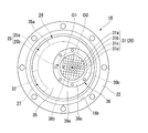
- the plurality of pores 31 are arranged in a grid pattern in the plan view of the barrier 36a.
- the plurality of pores 31 are arranged at equal intervals in a direction perpendicular to the one direction and a plurality of straight lines arranged to be parallel to each other at equal intervals in one direction. They are arranged at the intersections with a plurality of other straight lines that are arranged so as to be parallel to each other.
- the plurality of pores 31 have a plurality of first pores 31a, a plurality of second pores 31b, a plurality of third pores 31c, and a plurality of fourth pores 31d.
- one first pore 31a is disposed at a position that coincides with the central axis O2 in plan view, and the other plurality of first pores 31a are the first first pores 31a.
- the pores 31a are arranged so as to surround a square ring.
- the plurality of second pores 31b, the plurality of third pores 31c, and the plurality of fourth pores 31d are also arranged in a square ring shape, and the plurality of pores 31 extend from the inside to the outside in the swirl radial direction.
- the first pore 31a, the second pore 31b, the third pore 31c, and the fourth pore 31d are arranged in this order.
- the plurality of fourth pores 31d of the present embodiment are arranged in parallel with the square sides formed by the plurality of third pores 31c, but are not arranged near the corners of the square.
- Each pore 31 is formed in a substantially circular shape in plan view.
- the inner diameters of the plurality of pores 31 gradually increase from the pores 31 located on the outer side in the swirling radial direction toward the pores 31 located on the inner side, that is, the fourth pore 31d, the third pore 31c,
- the two pores 31b and the first pore 31a increase in order.
- the inner diameter of the pore 31 located inside the turning radius direction is larger than the inner diameter of the pore 31 located outside the turning radius direction.
- each inner diameter of the plurality of first pores 31a is 1.5 mm
- each inner diameter of the plurality of second pores 31b is 1.3 mm
- each of the plurality of third pores 31c are examples of the plurality of third pores 31c.
- the inner diameter is 0.9 mm, and each inner diameter of the plurality of fourth pores 31d is 0.4 mm.
- the inner diameter of each pore 31 is constant over the entire length of each flow path.
- the flow resistance of the pores 31 is decreased. Therefore, the flow resistance of the plurality of pores 31 is changed from the pores 31 positioned outside in the swirl radial direction to the pores 31 positioned inside. It gradually decreases as you go to.
- the flow resistance of the pores 31 located on the inner side in the swirl radial direction is lower than the flow resistance of the pores 31 located on the outer side in the swirl radial direction.
- the two attachment members 11 and 12 are relatively displaced while elastically deforming the elastic body 13 when a vibration is input. Then, the liquid pressure of at least one of the main liquid chamber 14 and the sub liquid chamber 15 fluctuates, and the liquid L tries to flow between the main liquid chamber 14 and the sub liquid chamber 15 through the restriction passage 24. At this time, the liquid flows into the restriction passage 24 through one of the first communication portion 26 and the second communication portion 27, passes through the main body flow path 25, and then passes through the first communication portion 26 and the second communication portion 27. It flows out of the restricted passage 24 through the other of them.
- the pores 31 are caused to drop while being lost by the barrier 36a in which these pores 31 are formed. Since it circulates, the flow velocity of the liquid L flowing into the main liquid chamber 14 can be suppressed. Moreover, since the liquid L circulates through the plurality of pores 31 instead of a single pore, the liquid L can be branched and circulated, and the liquid L that has passed through the individual pores 31 can be circulated. The flow rate can be reduced.
- the vibration isolator 10 Even if a large load (vibration) is input to the vibration isolator 10, the liquid L that has flowed into the main liquid chamber 14 through the pores 31, the liquid L in the main liquid chamber 14, It is possible to suppress the flow velocity difference generated between the two, and to suppress the generation of vortices due to the flow velocity difference and the generation of bubbles due to the vortices. Even if bubbles are generated not in the main liquid chamber 14 but in the restriction passage 24, the generated bubbles are separated from each other in the main liquid chamber 14 by passing the liquid L through the plurality of pores 31. Therefore, it is possible to prevent the bubbles from joining and growing and to easily maintain the bubbles in a finely dispersed state. As described above, the generation of bubbles itself can be suppressed, and even if bubbles are generated, the bubbles can be easily maintained in a finely dispersed state. However, it is possible to suppress the generated abnormal noise.
- the swirl chamber 25b changes from the plurality of pores 31 to the outer fine pore 31 in the swirl radial direction (for example, the third fine hole 31c and the fourth fine hole 31d).
- the flow rate of the liquid L that flows in and flows out into the main liquid chamber 14 is higher than that when it flows into the inner pores 31 (for example, the first pore 31a and the second pore 31b) in the swirling radial direction.
- the flow resistance of the pores 31 located on the inner side in the swirl radial direction is lower than the flow resistance of the pores 31 located on the outer side in the swirl radial direction.
- the liquid L flowing through the outer pore 31 in the swirl radial direction is caused to have a larger pressure loss and its flow rate is reduced. Can do. Therefore, the flow rate difference generated between the liquid L that has flowed into the main liquid chamber 14 through the fine pores 31 in the swirling radial direction among the plurality of fine holes 31 and the liquid L in the main liquid chamber 14. Can be suppressed, and the generation of vortices due to the flow velocity difference and the generation of bubbles due to the vortices can be suppressed.
- the flow velocity of the swirl flow in the vortex chamber 25b gradually decreases from the outside to the inside in the swirl radial direction.
- the flow resistance of the plurality of pores 31 is gradually decreased from the pore 31 located on the outer side in the swirling radial direction toward the pore 31 located on the inner side.
- the amount of decrease in the flow velocity of the liquid L can be gradually decreased from the outer side to the inner side in the swirl radial direction, so that the flow velocity of the liquid that has passed through the plurality of pores 31 is made uniform regardless of the position in the swirl radial direction. be able to.
- a lid portion 37 is used instead of the lid portion 36 of the above embodiment.
- the lid part 37 is a member formed of metal or resin.
- the lid portion 37 includes a disk-shaped barrier 37a extending in a direction perpendicular to the vortex axis, a connecting portion 36b extending upward from the outer peripheral edge of the barrier 37a, and a flange 36c. Yes.
- the lower surface of the barrier 37a extends in a direction perpendicular to the vortex axis, and the distance between the upper surface and the lower surface of the barrier 37a in the vortex axis direction gradually decreases from the outer side to the inner side in the turning radius direction. For this reason, the plate
- the first communication portion 26 includes a plurality of pores 38 formed so as to penetrate the barrier 37a in the vortex axis direction.
- the plurality of pores 38 are arranged in the same manner as the plurality of pores 31 of the above-described embodiment in plan view, and each pore 38 is formed in a substantially circular shape in plan view.
- the inner diameters of the plurality of pores 38 are all the same, and the inner diameter of each pore 38 is constant over the entire length of each flow path.
- the flow path lengths of the plurality of pores 38 also differ from the pores 38 positioned on the outer side in the swirl radial direction. It decreases gradually toward the pore 38 located inside.
- the flow path length of the pores 38 located on the inner side in the swirl radial direction is shorter than the flow path length of the pores 38 located on the outer side in the swirl radial direction.
- the flow resistance of the pores 38 located on the inner side in the turning radial direction is lower than the flow resistance of the pores 38 located on the outer side in the turning radial direction.
- the flow path length of the pore is the length of the pore measured along the central axis of the pore. Also in this modification, the same effect as the above-described embodiment can be obtained.
- the plurality of pores 31 have four types of pores 31 including a first pore 31a, a second pore 31b, a third pore 31c, and a fourth pore 31d.
- a first pore 31a a first pore 31a
- a second pore 31b a third pore 31c
- a fourth pore 31d a fourth pore 31d.
- One of the two types of pores is provided on the inner side of the swirling radial direction
- the other of the two types of pores is provided on the outer side of the swirling radial direction.
- the flow resistance of the pores only needs to be lower than the flow resistance of the other pore.
- the plurality of pores 31 of the above embodiment differ only in the inner diameter
- the plurality of pores 38 in the modified example differ only in the flow path length. Any of the channel lengths may be different.
- each of the plurality of pores 31 and 38 is formed in a substantially circular shape in plan view, but may be formed in a non-circular shape in plan view, for example, an elliptical shape or a polygonal shape.
- the plurality of pores 31 and 38 may be formed in a tapered shape that gradually decreases in diameter along the axial direction from the vortex chamber 25b side to the main liquid chamber 14 side.
- the inner diameter of the pore means the smallest inner diameter of the pore.
- the plurality of pores 31 and 38 may be arranged in a multiple annular shape coaxial with the vortex axis in plan view, or may be arranged on a plurality of straight lines extending radially from the vortex axis in plan view. Good.
- the plurality of pores 31 and 38 are formed extending in one direction, but the pores may be bent in the middle.
- the flow path length of the pore is the length of the pore measured along the central axis of the pore.
- the second communication portion 27 may include a plurality of openings and pores that open into the sub liquid chamber 15.
- the vortex chamber 25b is arranged at the connection portion with the first communication portion 26, while the vortex chamber is arranged at the connection portion with the second communication portion 27,
- the vortex chamber may not be disposed at the connection portion with the first communication portion 26, and the second communication portion 27 may include a plurality of pores.
- the vortex chamber arranged at the connection portion with the second communication portion 27 forms a swirling flow of the liquid L according to the flow velocity of the liquid L flowing from the first communication portion 26, The liquid L is caused to flow into the secondary liquid chamber 15 through the plurality of pores of the second communication portion 27.
- vortex chambers may be separately arranged at both connection portions between the first communication portion 26 and the second communication portion 27.
- the central axis O2 of the vortex chamber 25b is arranged at a position different from the central axis O1 in plan view, but the vortex chamber 25b may be arranged coaxially with the central axis O1.
- the central axis O2 of the vortex chamber 25b is parallel to the central axis O1, but the vortex chamber 25b may be arranged so that the central axis O2 is not parallel to the central axis O1.
- the partition member 16 may have any shape as long as the main liquid chamber 14 and the sub liquid chamber 15 can be partitioned.
- the lid portion 36 includes the barrier 36a, the coupling portion 36b, and the flange 36c.
- the lid portion 36 is formed in a plate shape extending in a direction perpendicular to the vortex axis. Also good.
- a plurality of pores are formed in the lid 36, and at least a portion of the lid 36 where the plurality of pores are formed corresponds to the barrier of the present invention.
- the partition plate 35 is formed with a recess that opens toward the auxiliary liquid chamber 15, and the lid portion closes the opening of the recess from the auxiliary liquid chamber 15 side, whereby a vortex is formed between the lid portion and the recess.
- a chamber may be formed, and a plurality of holes communicating the vortex chamber and the main liquid chamber 14 may be formed in the partition plate 35 so as to open to the bottom surface of the recess.
- the portion where the plurality of pores are formed in the partition plate 35 corresponds to the barrier of the present invention.
- partition member 16 is arrange
- the sub liquid chamber 15 may be formed from the lower surface to the bottom surface of the diaphragm 20.
- the compression type vibration isolator 10 which a positive pressure acts on the main liquid chamber 14 by the support load acting was demonstrated, the main liquid chamber 14 is located in the vertical lower side, and The present invention can also be applied to a suspension type vibration isolator in which the sub liquid chamber 15 is mounted so as to be positioned on the upper side in the vertical direction and a negative pressure is applied to the main liquid chamber 14 when a support load is applied.
- the partition member 16 partitioned off the liquid chamber 19 in the 1st attachment member 11 into the main liquid chamber 14 and the sub liquid chamber 15 which have the elastic body 13 in a part of wall surface.
- the elastic body 13 may be provided, and instead of providing the secondary liquid chamber 15, a pressure receiving liquid chamber having the elastic body 13 at a part of the wall surface may be provided.
- the partition member 16 partitions the liquid chamber 19 in the first mounting member 11 in which the liquid L is sealed into the first liquid chamber 14 and the second liquid chamber 15, and the first liquid chamber 14 and the second liquid chamber 15. At least one of the above can be appropriately changed to another configuration having the elastic body 13 in a part of the wall surface.
- the vibration isolator 10 according to the present invention is not limited to an engine mount of a vehicle, and can be applied to other than the engine mount.
- the present invention can be applied to a mount of a generator mounted on a construction machine, or can be applied to a mount of a machine installed in a factory or the like.
- both mounting members are relatively displaced while elastically deforming the elastic body, and the hydraulic pressure of at least one of the first liquid chamber and the second liquid chamber varies. Then, the liquid tries to flow between the first liquid chamber and the second liquid chamber through the restriction passage. At this time, the liquid flows into the restriction passage through one of the first communication portion and the second communication portion, passes through the main body flow path, and then passes through the other of the first communication portion and the second communication portion. Spill from.
- the liquid flows into the first liquid chamber or the second liquid chamber from the restriction passage through the plurality of pores, the liquid flows through each of the pores while being subjected to pressure loss by the barrier in which these pores are formed.
- the flow rate of the liquid flowing into the first liquid chamber or the second liquid chamber can be suppressed.
- the liquid flows through a plurality of pores instead of a single pore, it is possible to divide the liquid into a plurality of channels and reduce the flow rate of the liquid that has passed through the individual pores. Can do.
- a large load vibration
- the liquid that has passed through the pores and flowed into the first liquid chamber or the second liquid chamber, and the first liquid chamber or the second liquid chamber It is possible to suppress the difference in flow velocity generated between the liquid and the liquid and the generation of vortices due to the flow velocity difference and the generation of bubbles due to the vortices.
- the generated bubbles are caused to pass between the first liquid chamber or the second liquid by passing the liquid through the plurality of pores. It becomes possible to make it separate in a liquid chamber, it can suppress that a bubble joins and grows, and can make it easy to maintain a bubble in the state disperse
- the vortex chamber provided in the connection portion with one of the first communication portion and the second communication portion has the first communication portion and the second communication portion.
- the liquid flowing into the vortex chamber flows from the outer side to the inner side in the swirl radial direction while swirling around the vortex axis along the central axis of the vortex chamber.
- the fluid friction of the liquid, etc. the flow velocity of the swirling flow decreases from the outer side to the inner side in the swirling radial direction.
- the swirl chamber flows from the plurality of pores into the outer pores in the swirling radial direction and flows out to the first liquid chamber or the second liquid chamber.
- the flow velocity of the liquid tends to be higher than when it flows into the pores inside the swirling radial direction. That is, the flow velocity of the liquid flowing through the plurality of pores tends to be higher on the outer side than on the inner side in the swirling radial direction.
- the flow resistance of the pores located on the inner side in the turning radial direction is lower than the flow resistance of the pores located on the outer side in the turning radial direction.
- the liquid flowing through the outer pore in the swirling radial direction can be caused to have a larger pressure loss and the flow velocity can be reduced. Therefore, between the liquid that has passed through the pores on the outer side in the swirling radial direction and flowed into the first liquid chamber or the second liquid chamber and the liquid in the first liquid chamber or the second liquid chamber among the plurality of pores. It is possible to suppress the flow velocity difference caused by the vortex, and it is possible to suppress the generation of vortices due to the flow velocity difference and the generation of bubbles due to the vortices.
- an inner diameter of the pore located inside the turning radius direction may be larger than an inner diameter of the pore located outside the turning radius direction.
- the inner diameter of the pore When the inner diameter of the pore is increased, the flow resistance of the pore is reduced. For this reason, among the plurality of pores, the inner diameter of the pores located inside the swirling radial direction is made larger than the inner diameter of the pores located outside the swirling radial direction, thereby being positioned inside the swirling radial direction.
- the flow resistance of the pores to be made can be made lower than the flow resistance of the pores located on the outer side in the turning radius direction.
- the channel length of the pores located on the inner side in the turning radius direction may be shorter than the channel length of the pores located on the outer side in the turning radius direction.
- the flow resistance of the pore decreases.
- the flow path length of the pores located on the inner side in the swirl radial direction is made shorter than the flow path length of the pores located on the outer side in the swirl radial direction, thereby turning the swirl diameter
- the flow resistance of the pores located inside in the direction can be made lower than the flow resistance of the pores located outside in the turning radial direction.
- the flow resistance of the plurality of pores may be gradually reduced from the pores located on the outer side in the swirling radial direction toward the pores located on the inner side.
- the flow velocity of the swirl flow in the vortex chamber gradually decreases from the outside to the inside in the swirl radial direction. For this reason, by gradually decreasing the flow resistance of the plurality of pores from the pores located on the outer side in the swirling radial direction toward the pores located on the inner side, the flow velocity reduction amount of the liquid that has passed through the plurality of pores can be reduced. It can be gradually decreased from the outside in the swirl radial direction to the inside, and therefore the flow velocity of the liquid that has passed through the plurality of pores can be made uniform regardless of the position in the swirl radial direction.
Abstract
Passage de limitation (24) pourvu : d'une première section de communication (26) ouverte sur une première chambre de liquide ; une seconde section de communication (27) ouverte sur une seconde chambre de liquide ; et un passage d'écoulement de corps (25) pour assurer une communication entre la première section de communication et la seconde section de communication. La première section de communication et/ou la seconde section de communication sont pourvues d'une pluralité de trous fins (31). Dans la partie du passage d'écoulement de corps, qui est reliée à la première section de communication et/ou à la seconde section de communication, est disposée une chambre de turbulence (25b), la chambre de turbulence (25b) formant l'écoulement turbulent de liquide en fonction de la vitesse d'écoulement de liquide s'écoulant à partir de la première section de communication ou de la seconde section de communication qui n'est pas reliée à la partie du passage d'écoulement de corps, ce qui amène le liquide de l'écoulement turbulent à s'écouler par les trous fins. Une paroi de barrière (36a) dans laquelle la pluralité de trous fins sont formés s'étend dans une direction croisant un axe de turbulence s'étendant le long de l'axe central (O2) de la chambre de turbulence. Parmi la pluralité de trous fins, les trous fins situés sur le côté intérieur dans une direction radiale de turbulence qui coupe l'axe de turbulence sur une vue en plan de la paroi de barrière ont une résistance à l'écoulement inférieure à celle des trous fins situés sur le côté extérieur dans la direction radiale de turbulence.
Priority Applications (3)
| Application Number | Priority Date | Filing Date | Title |
|---|---|---|---|
| US16/490,746 US11143267B2 (en) | 2017-05-18 | 2018-02-08 | Vibration damping device |
| EP18802069.7A EP3626997B1 (fr) | 2017-05-18 | 2018-02-08 | Dispositif d'amortissement de vibrations |
| CN201880019703.5A CN110446879A (zh) | 2017-05-18 | 2018-02-08 | 隔振装置 |
Applications Claiming Priority (2)
| Application Number | Priority Date | Filing Date | Title |
|---|---|---|---|
| JP2017098942A JP6824818B2 (ja) | 2017-05-18 | 2017-05-18 | 防振装置 |
| JP2017-098942 | 2017-05-18 |
Publications (1)
| Publication Number | Publication Date |
|---|---|
| WO2018211754A1 true WO2018211754A1 (fr) | 2018-11-22 |
Family
ID=64273775
Family Applications (1)
| Application Number | Title | Priority Date | Filing Date |
|---|---|---|---|
| PCT/JP2018/004388 WO2018211754A1 (fr) | 2017-05-18 | 2018-02-08 | Dispositif d'amortissement de vibrations |
Country Status (5)
| Country | Link |
|---|---|
| US (1) | US11143267B2 (fr) |
| EP (1) | EP3626997B1 (fr) |
| JP (1) | JP6824818B2 (fr) |
| CN (1) | CN110446879A (fr) |
| WO (1) | WO2018211754A1 (fr) |
Cited By (1)
| Publication number | Priority date | Publication date | Assignee | Title |
|---|---|---|---|---|
| US11428290B2 (en) | 2017-12-26 | 2022-08-30 | Prospira Corporation | Vibration isolating device |
Families Citing this family (1)
| Publication number | Priority date | Publication date | Assignee | Title |
|---|---|---|---|---|
| JP6577911B2 (ja) * | 2016-06-23 | 2019-09-18 | 株式会社ブリヂストン | 防振装置 |
Citations (6)
| Publication number | Priority date | Publication date | Assignee | Title |
|---|---|---|---|---|
| JPS63308245A (ja) * | 1987-04-03 | 1988-12-15 | カウチュ マニュファクチュールエ プラスチーク | 一体油圧ダンパーを備えた弾性振動隔絶取付具及び流体を導通させるための調節可能な通路を備えた剛性隔壁 |
| JP2012026510A (ja) * | 2010-07-23 | 2012-02-09 | Tokai Rubber Ind Ltd | 流体封入式防振装置 |
| JP2012172832A (ja) | 2011-02-24 | 2012-09-10 | Toyo Tire & Rubber Co Ltd | 液封入式防振装置 |
| WO2014196284A1 (fr) * | 2013-06-03 | 2014-12-11 | 株式会社ブリヂストン | Dispositif d'amortissement des vibrations |
| WO2016027606A1 (fr) * | 2014-08-20 | 2016-02-25 | 株式会社ブリヂストン | Dispositif d'amortissement des vibrations |
| JP2017098942A (ja) | 2001-05-29 | 2017-06-01 | 株式会社半導体エネルギー研究所 | 半導体装置 |
Family Cites Families (14)
| Publication number | Priority date | Publication date | Assignee | Title |
|---|---|---|---|---|
| JPS6040843A (ja) * | 1983-08-15 | 1985-03-04 | Bridgestone Corp | 防振装置用オリフイス構造 |
| FR2697604B1 (fr) * | 1992-11-02 | 1995-01-27 | Hutchinson | Perfectionnements aux supports antivibratoires hydrauliques. |
| JP2006144806A (ja) * | 2003-04-04 | 2006-06-08 | Toyo Tire & Rubber Co Ltd | 液封入式防振装置 |
| JP2007182930A (ja) | 2006-01-06 | 2007-07-19 | Toyo Tire & Rubber Co Ltd | 液封入式防振装置 |
| JP5095763B2 (ja) | 2010-01-21 | 2012-12-12 | 東洋ゴム工業株式会社 | 液封入式防振装置 |
| WO2013140708A1 (fr) | 2012-03-23 | 2013-09-26 | 東海ゴム工業株式会社 | Dispositif de prévention de vibrations de fluide étanche |
| JP6134629B2 (ja) | 2013-10-25 | 2017-05-24 | 株式会社ブリヂストン | 防振装置 |
| JP6274927B2 (ja) | 2014-03-17 | 2018-02-07 | 株式会社ブリヂストン | 防振装置 |
| JP6448926B2 (ja) | 2014-06-23 | 2019-01-09 | 住友理工株式会社 | 流体封入式防振装置 |
| EP3184852B1 (fr) | 2014-08-20 | 2018-12-19 | Bridgestone Corporation | Dispositif d'amortissement de vibrations |
| JP6450619B2 (ja) * | 2015-03-19 | 2019-01-09 | 株式会社ブリヂストン | 防振装置 |
| JPWO2017222014A1 (ja) * | 2016-06-22 | 2019-04-11 | 株式会社ブリヂストン | 防振装置 |
| JP6674334B2 (ja) * | 2016-06-23 | 2020-04-01 | 株式会社ブリヂストン | 防振装置 |
| EP3617546A4 (fr) * | 2017-04-27 | 2021-01-20 | Bridgestone Corporation | Dispositif d'amortissement de vibrations |
-
2017
- 2017-05-18 JP JP2017098942A patent/JP6824818B2/ja active Active
-
2018
- 2018-02-08 EP EP18802069.7A patent/EP3626997B1/fr active Active
- 2018-02-08 US US16/490,746 patent/US11143267B2/en active Active
- 2018-02-08 WO PCT/JP2018/004388 patent/WO2018211754A1/fr unknown
- 2018-02-08 CN CN201880019703.5A patent/CN110446879A/zh active Pending
Patent Citations (6)
| Publication number | Priority date | Publication date | Assignee | Title |
|---|---|---|---|---|
| JPS63308245A (ja) * | 1987-04-03 | 1988-12-15 | カウチュ マニュファクチュールエ プラスチーク | 一体油圧ダンパーを備えた弾性振動隔絶取付具及び流体を導通させるための調節可能な通路を備えた剛性隔壁 |
| JP2017098942A (ja) | 2001-05-29 | 2017-06-01 | 株式会社半導体エネルギー研究所 | 半導体装置 |
| JP2012026510A (ja) * | 2010-07-23 | 2012-02-09 | Tokai Rubber Ind Ltd | 流体封入式防振装置 |
| JP2012172832A (ja) | 2011-02-24 | 2012-09-10 | Toyo Tire & Rubber Co Ltd | 液封入式防振装置 |
| WO2014196284A1 (fr) * | 2013-06-03 | 2014-12-11 | 株式会社ブリヂストン | Dispositif d'amortissement des vibrations |
| WO2016027606A1 (fr) * | 2014-08-20 | 2016-02-25 | 株式会社ブリヂストン | Dispositif d'amortissement des vibrations |
Non-Patent Citations (1)
| Title |
|---|
| See also references of EP3626997A4 * |
Cited By (1)
| Publication number | Priority date | Publication date | Assignee | Title |
|---|---|---|---|---|
| US11428290B2 (en) | 2017-12-26 | 2022-08-30 | Prospira Corporation | Vibration isolating device |
Also Published As
| Publication number | Publication date |
|---|---|
| CN110446879A (zh) | 2019-11-12 |
| EP3626997A1 (fr) | 2020-03-25 |
| US11143267B2 (en) | 2021-10-12 |
| EP3626997A4 (fr) | 2020-09-02 |
| EP3626997B1 (fr) | 2021-07-07 |
| US20200080616A1 (en) | 2020-03-12 |
| JP2018194102A (ja) | 2018-12-06 |
| JP6824818B2 (ja) | 2021-02-03 |
Similar Documents
| Publication | Publication Date | Title |
|---|---|---|
| JP6450619B2 (ja) | 防振装置 | |
| JP6391186B2 (ja) | 防振装置、およびキャビテーション崩壊に起因する異音の発生を抑制する方法 | |
| WO2018198442A1 (fr) | Dispositif d'amortissement de vibrations | |
| WO2018211754A1 (fr) | Dispositif d'amortissement de vibrations | |
| WO2017221818A1 (fr) | Dispositif d'amortissement de vibrations | |
| WO2018198444A1 (fr) | Dispositif d'amortissement de vibrations | |
| WO2017221823A1 (fr) | Dispositif d'amortissement de vibrations | |
| JP7145165B2 (ja) | 防振装置 | |
| JP6822860B2 (ja) | 防振装置 | |
| JP6975628B2 (ja) | 防振装置 | |
| JP6836458B2 (ja) | 防振装置 | |
| WO2018193895A1 (fr) | Dispositif d'amortissement des vibrations | |
| JP6577911B2 (ja) | 防振装置 | |
| WO2019131043A1 (fr) | Dispositif d'isolation contre les vibrations | |
| JP6853674B2 (ja) | 防振装置 | |
| WO2019117062A1 (fr) | Dispositif d'amortissement de vibrations | |
| JP7161842B2 (ja) | 防振装置 | |
| JP2019203542A (ja) | 防振装置 | |
| JP2018179190A (ja) | 防振装置 |
Legal Events
| Date | Code | Title | Description |
|---|---|---|---|
| 121 | Ep: the epo has been informed by wipo that ep was designated in this application |
Ref document number: 18802069 Country of ref document: EP Kind code of ref document: A1 |
|
| NENP | Non-entry into the national phase |
Ref country code: DE |
|
| ENP | Entry into the national phase |
Ref document number: 2018802069 Country of ref document: EP Effective date: 20191218 |