WO2018211664A1 - X-ray spectrometer - Google Patents
X-ray spectrometer Download PDFInfo
- Publication number
- WO2018211664A1 WO2018211664A1 PCT/JP2017/018701 JP2017018701W WO2018211664A1 WO 2018211664 A1 WO2018211664 A1 WO 2018211664A1 JP 2017018701 W JP2017018701 W JP 2017018701W WO 2018211664 A1 WO2018211664 A1 WO 2018211664A1
- Authority
- WO
- WIPO (PCT)
- Prior art keywords
- ray
- slit
- rays
- characteristic
- sample
- Prior art date
Links
Images


Classifications
-
- G—PHYSICS
- G01—MEASURING; TESTING
- G01N—INVESTIGATING OR ANALYSING MATERIALS BY DETERMINING THEIR CHEMICAL OR PHYSICAL PROPERTIES
- G01N23/00—Investigating or analysing materials by the use of wave or particle radiation, e.g. X-rays or neutrons, not covered by groups G01N3/00 – G01N17/00, G01N21/00 or G01N22/00
- G01N23/22—Investigating or analysing materials by the use of wave or particle radiation, e.g. X-rays or neutrons, not covered by groups G01N3/00 – G01N17/00, G01N21/00 or G01N22/00 by measuring secondary emission from the material
- G01N23/225—Investigating or analysing materials by the use of wave or particle radiation, e.g. X-rays or neutrons, not covered by groups G01N3/00 – G01N17/00, G01N21/00 or G01N22/00 by measuring secondary emission from the material using electron or ion
-
- G—PHYSICS
- G01—MEASURING; TESTING
- G01N—INVESTIGATING OR ANALYSING MATERIALS BY DETERMINING THEIR CHEMICAL OR PHYSICAL PROPERTIES
- G01N23/00—Investigating or analysing materials by the use of wave or particle radiation, e.g. X-rays or neutrons, not covered by groups G01N3/00 – G01N17/00, G01N21/00 or G01N22/00
- G01N23/22—Investigating or analysing materials by the use of wave or particle radiation, e.g. X-rays or neutrons, not covered by groups G01N3/00 – G01N17/00, G01N21/00 or G01N22/00 by measuring secondary emission from the material
-
- G—PHYSICS
- G01—MEASURING; TESTING
- G01N—INVESTIGATING OR ANALYSING MATERIALS BY DETERMINING THEIR CHEMICAL OR PHYSICAL PROPERTIES
- G01N23/00—Investigating or analysing materials by the use of wave or particle radiation, e.g. X-rays or neutrons, not covered by groups G01N3/00 – G01N17/00, G01N21/00 or G01N22/00
- G01N23/20—Investigating or analysing materials by the use of wave or particle radiation, e.g. X-rays or neutrons, not covered by groups G01N3/00 – G01N17/00, G01N21/00 or G01N22/00 by using diffraction of the radiation by the materials, e.g. for investigating crystal structure; by using scattering of the radiation by the materials, e.g. for investigating non-crystalline materials; by using reflection of the radiation by the materials
- G01N23/207—Diffractometry using detectors, e.g. using a probe in a central position and one or more displaceable detectors in circumferential positions
- G01N23/2076—Diffractometry using detectors, e.g. using a probe in a central position and one or more displaceable detectors in circumferential positions for spectrometry, i.e. using an analysing crystal, e.g. for measuring X-ray fluorescence spectrum of a sample with wavelength-dispersion, i.e. WDXFS
-
- G—PHYSICS
- G01—MEASURING; TESTING
- G01N—INVESTIGATING OR ANALYSING MATERIALS BY DETERMINING THEIR CHEMICAL OR PHYSICAL PROPERTIES
- G01N23/00—Investigating or analysing materials by the use of wave or particle radiation, e.g. X-rays or neutrons, not covered by groups G01N3/00 – G01N17/00, G01N21/00 or G01N22/00
- G01N23/20—Investigating or analysing materials by the use of wave or particle radiation, e.g. X-rays or neutrons, not covered by groups G01N3/00 – G01N17/00, G01N21/00 or G01N22/00 by using diffraction of the radiation by the materials, e.g. for investigating crystal structure; by using scattering of the radiation by the materials, e.g. for investigating non-crystalline materials; by using reflection of the radiation by the materials
- G01N23/207—Diffractometry using detectors, e.g. using a probe in a central position and one or more displaceable detectors in circumferential positions
-
- G—PHYSICS
- G01—MEASURING; TESTING
- G01N—INVESTIGATING OR ANALYSING MATERIALS BY DETERMINING THEIR CHEMICAL OR PHYSICAL PROPERTIES
- G01N23/00—Investigating or analysing materials by the use of wave or particle radiation, e.g. X-rays or neutrons, not covered by groups G01N3/00 – G01N17/00, G01N21/00 or G01N22/00
- G01N23/22—Investigating or analysing materials by the use of wave or particle radiation, e.g. X-rays or neutrons, not covered by groups G01N3/00 – G01N17/00, G01N21/00 or G01N22/00 by measuring secondary emission from the material
- G01N23/223—Investigating or analysing materials by the use of wave or particle radiation, e.g. X-rays or neutrons, not covered by groups G01N3/00 – G01N17/00, G01N21/00 or G01N22/00 by measuring secondary emission from the material by irradiating the sample with X-rays or gamma-rays and by measuring X-ray fluorescence
-
- G—PHYSICS
- G01—MEASURING; TESTING
- G01N—INVESTIGATING OR ANALYSING MATERIALS BY DETERMINING THEIR CHEMICAL OR PHYSICAL PROPERTIES
- G01N2223/00—Investigating materials by wave or particle radiation
- G01N2223/05—Investigating materials by wave or particle radiation by diffraction, scatter or reflection
- G01N2223/056—Investigating materials by wave or particle radiation by diffraction, scatter or reflection diffraction
-
- G—PHYSICS
- G01—MEASURING; TESTING
- G01N—INVESTIGATING OR ANALYSING MATERIALS BY DETERMINING THEIR CHEMICAL OR PHYSICAL PROPERTIES
- G01N2223/00—Investigating materials by wave or particle radiation
- G01N2223/07—Investigating materials by wave or particle radiation secondary emission
- G01N2223/076—X-ray fluorescence
-
- G—PHYSICS
- G01—MEASURING; TESTING
- G01N—INVESTIGATING OR ANALYSING MATERIALS BY DETERMINING THEIR CHEMICAL OR PHYSICAL PROPERTIES
- G01N2223/00—Investigating materials by wave or particle radiation
- G01N2223/07—Investigating materials by wave or particle radiation secondary emission
- G01N2223/079—Investigating materials by wave or particle radiation secondary emission incident electron beam and measuring excited X-rays
-
- G—PHYSICS
- G01—MEASURING; TESTING
- G01N—INVESTIGATING OR ANALYSING MATERIALS BY DETERMINING THEIR CHEMICAL OR PHYSICAL PROPERTIES
- G01N2223/00—Investigating materials by wave or particle radiation
- G01N2223/30—Accessories, mechanical or electrical features
- G01N2223/316—Accessories, mechanical or electrical features collimators
-
- G—PHYSICS
- G01—MEASURING; TESTING
- G01N—INVESTIGATING OR ANALYSING MATERIALS BY DETERMINING THEIR CHEMICAL OR PHYSICAL PROPERTIES
- G01N2223/00—Investigating materials by wave or particle radiation
- G01N2223/30—Accessories, mechanical or electrical features
- G01N2223/321—Accessories, mechanical or electrical features manipulator for positioning a part
-
- G—PHYSICS
- G01—MEASURING; TESTING
- G01N—INVESTIGATING OR ANALYSING MATERIALS BY DETERMINING THEIR CHEMICAL OR PHYSICAL PROPERTIES
- G01N2223/00—Investigating materials by wave or particle radiation
- G01N2223/30—Accessories, mechanical or electrical features
- G01N2223/33—Accessories, mechanical or electrical features scanning, i.e. relative motion for measurement of successive object-parts
-
- G—PHYSICS
- G01—MEASURING; TESTING
- G01N—INVESTIGATING OR ANALYSING MATERIALS BY DETERMINING THEIR CHEMICAL OR PHYSICAL PROPERTIES
- G01N2223/00—Investigating materials by wave or particle radiation
- G01N2223/50—Detectors
- G01N2223/501—Detectors array
- G01N2223/5015—Detectors array linear array
-
- G—PHYSICS
- G01—MEASURING; TESTING
- G01N—INVESTIGATING OR ANALYSING MATERIALS BY DETERMINING THEIR CHEMICAL OR PHYSICAL PROPERTIES
- G01N2223/00—Investigating materials by wave or particle radiation
- G01N2223/60—Specific applications or type of materials
- G01N2223/635—Specific applications or type of materials fluids, granulates
Definitions
- the present invention relates to an X-ray spectroscopic analyzer that detects the intensity of each wavelength by spectroscopically analyzing characteristic X-rays emitted from a sample irradiated with excitation rays such as primary X-rays and electron beams.
- the elemental analysis of the sample can be performed by measuring the intensity of such X-rays for each wavelength.
- Patent Documents 1 and 2 an excitation source that irradiates an analysis point on the surface of a sample with an excitation line, a spectral crystal that diffracts X-rays emitted from the sample irradiated with the excitation line, and diffraction by the spectral crystal
- An X-ray spectroscopic analyzer having a detector for detecting the emitted X-rays is described.
- characteristic X-rays are emitted from the analysis point in various directions.
- the wavelength of the characteristic X-ray and the incident angle to the spectral crystal satisfy the Bragg reflection condition. Only when it is satisfied, the characteristic X-ray is diffracted and reflected. Therefore, the wavelength of the peak of the characteristic X-ray can be determined by measuring the intensity of the X-ray reflected by the spectroscopic crystal at various angles with an X-ray linear sensor.
- the wavelength of characteristic X-rays measured by the X-ray linear sensor may be not only one but also plural.
- the method of detecting the characteristic X-ray by measuring the intensity for each wavelength in this way is called “wavelength dispersion type”.
- wavelength dispersion type In addition to the wavelength dispersion type, there is an “energy dispersion type” that directly detects the energy of characteristic X-rays for each value of the energy, but the wavelength dispersion type has a higher resolution. Highly accurate elemental analysis can be performed.
- the problem to be solved by the present invention is to provide an X-ray spectroscopic analyzer capable of measuring the composition of a sample such as a liquid or powder having a uniform composition regardless of position with higher sensitivity than a conventional apparatus. It is to be.
- an excitation source for irradiating a predetermined irradiation region on the sample surface with an excitation ray for generating characteristic X-rays A spectroscopic crystal provided facing the irradiation region; A slit parallel to the irradiation region and a predetermined crystal plane of the spectral crystal provided between the irradiation region and the spectral crystal;
- An X-ray spectroscopic analysis apparatus including an X-ray linear sensor provided so that a plurality of detection elements are arranged in a direction perpendicular to the longitudinal direction of the slit has been proposed.
- the X-ray spectroscopic analysis device when a predetermined irradiation region on the sample surface is irradiated with an excitation beam, the X-ray spectroscopic analysis device changes various positions from within the irradiation region. Characteristic X-rays are emitted in various directions, and only those passing through the slit reach the spectroscopic crystal. When the irradiation region is divided into a plurality of linear portions parallel to the longitudinal direction of the slit, characteristic X-rays having a specific wavelength (specific wavelength) in the sample are emitted from a certain linear portion.
- the elemental analysis of the sample can be performed by obtaining the peak wavelength and intensity of the characteristic X-ray from the detection signal of the X-ray linear sensor. Further, since characteristic X-rays from the linear portion are detected, a larger amount of characteristic X-rays are measured than in the conventional apparatus for detecting characteristic X-rays from the analysis point, and the analysis sensitivity is increased.
- the wavelength of X-rays incident on the spectroscopic crystal at an angle satisfying the Bragg reflection condition from each of a plurality of (virtually divided) linear portions on the sample surface is determined. And this cannot be changed. Focusing on one linear part, the angle from the linear part through the slit and entering the specified crystal surface of the spectroscopic crystal is determined, and the wavelength that satisfies the Bragg reflection condition (specific wavelength) at that angle Only X-rays are diffracted at the crystal plane.
- the upper and lower limits of the wavelength range that can be measured by the specific wavelengths respectively corresponding to the linear portions located at both ends of the irradiation region are determined, it is possible to detect characteristic X-rays of wavelengths outside that range.
- the types of elements that can be analyzed by one apparatus are limited.
- the X-ray linear sensor that the spectroscopic crystal expects since the range of the X-ray linear sensor that the spectroscopic crystal expects is limited, when the position and orientation of the spectroscopic crystal are set with respect to characteristic X-rays of a specific wavelength emitted from a specific linear portion, other linear shapes Even if characteristic X-rays of other wavelengths emitted from the portion enter the spectroscopic crystal at an angle that satisfies the Bragg reflection condition, the diffracted X-rays may not be received and detected by the X-ray linear sensor. Furthermore, the detection sensitivity cannot be increased to measure trace elements, and the wavelength (energy) resolution cannot be increased to perform highly accurate measurement. That is, there is a problem that the X-ray spectroscopic analyzer of the prior application can only perform measurement under predetermined conditions.
- the present invention has been made for the purpose of increasing the degree of freedom of measurement by improving the above points in the X-ray spectroscopic analyzer of the prior application.
- the first aspect of the X-ray spectroscopic analysis apparatus comprises: a) an excitation source that irradiates a predetermined irradiation region on the sample surface with an excitation ray for generating characteristic X-rays; b) a diffractive member provided facing the irradiated area; c) a slit member provided between the irradiation region and the diffraction member, and having a slit parallel to the irradiation region and a predetermined surface of the diffraction member; d) an X-ray linear sensor having a light incident surface in which a plurality of detection elements are arranged in a direction perpendicular to the longitudinal direction of the slit; and e) by moving the diffractive member in a plane perpendicular to the longitudinal direction.
- a first moving mechanism that changes an angle formed between the sample surface and the predetermined surface, or / and a distance between the sample surface and the predetermined surface; f) By moving the X-ray linear sensor in a plane perpendicular to the longitudinal direction, the X-ray linear sensor is positioned on the path of the characteristic X-ray diffracted by the predetermined plane through the slit. And a second moving mechanism.
- the diffraction member is, for example, a spectral crystal or an artificial multilayer film.
- the predetermined plane is a crystal plane of a spectral crystal or an interface of an artificial multilayer film.
- it is preferably used for measuring a sample that can be regarded as having a uniform composition regardless of position, such as a liquid or a powder. Can do.
- X-rays having different wavelengths emitted from the same position on the sample surface can be detected, and X-rays having the same wavelength emitted from different positions on the sample surface can be detected. Since it can also detect, the sample from which a composition differs with positions can also be measured.
- the first moving mechanism for example, a rotation mechanism that rotates a diffraction member around an axis parallel to the longitudinal direction of the slit, or a distance between the sample surface and the predetermined surface within a plane perpendicular to the longitudinal direction.
- a linear motion mechanism to be changed, or a mechanism having both of them can be used.
- a linear motion mechanism that changes the distance of the incident surface, or a mechanism that includes both of them can be used.
- the X-ray spectroscopic analysis apparatus includes a first moving mechanism that moves a diffractive member that is incident on a characteristic X-ray that is generated in a predetermined irradiation region of a sample surface and passes through a slit;
- a second movement mechanism is provided for moving an X-ray linear sensor that detects characteristic X-rays diffracted on a plane (such as a crystal plane of a spectral crystal).
- a plane such as a crystal plane of a spectral crystal.
- characteristic X-rays emitted from the target element can be measured by appropriately changing the measurement wavelength range of X-rays.
- the distance from the sample surface to a predetermined surface of the diffractive member is changed by the first moving mechanism, and the characteristic X emitted from the irradiation region is changed.
- the wavelength width of the X-ray incident on each of the plurality of detection elements constituting the incident surface of the X-ray linear sensor changes. Thereby, the wavelength (energy) resolution of the measurement can be changed.
- the wavelength (energy) resolution of the measurement can be changed by changing the distance from the predetermined surface of the diffractive member to the light incident surface of the X-ray linear sensor by the second mechanism.
- the degree of freedom of measurement can be increased as compared with the conventional case.
- the second aspect of the X-ray spectroscopic analyzer which has been made to achieve the above object, a) an excitation source that irradiates a predetermined irradiation region on the sample surface with an excitation ray for generating characteristic X-rays; b) a diffractive member provided facing the irradiated area; c) a variable slit member provided between the irradiation region and the diffractive member, having a slit parallel to the irradiation region and a predetermined surface of the diffractive member, and capable of changing an opening width of the slit; d) An X-ray linear having a light incident surface that is arranged on a path of characteristic X-rays that pass through the slit and is diffracted by the predetermined surface, and in which a plurality of detection elements are arranged in a direction perpendicular to the longitudinal direction of the slit. And a sensor.
- the characteristic X-rays generated in the irradiation region are changed by changing the opening width of the slit of the variable slit member provided between the irradiation region on the sample surface and the diffraction member.
- the amount of characteristic X-rays diffracted by the diffraction grating and incident on the X-ray linear sensor can be changed. That is, the resolution of wavelength (energy) can be increased by narrowing the opening width of the slit, and the measurement sensitivity can be increased by widening the opening width of the slit.
- variable slit member for example, one that changes the opening width of the slit by moving two rectangular slit plates arranged so that one side faces each other, or a plurality of slit plates having different opening widths Can be used that can be switched.
- the composition of a sample such as a liquid or a powder having a uniform composition regardless of the position is made higher than that of the conventional apparatus. It can be measured with sensitivity. In addition, the degree of freedom of measurement can be increased as compared with the X-ray spectroscopic analyzer of the prior application.
- the schematic block diagram of the X-ray-spectral-analysis apparatus of a prior application The perspective view which shows the path
- BRIEF DESCRIPTION OF THE DRAWINGS Schematic block diagram of one Example (Example 1) of the X-ray-spectral-analysis apparatus based on this invention.
- FIG. 3 The graph explaining the center position of the spectral crystal in the X-ray-spectral-analysis apparatus of Example 2, and the center position of an X-ray linear sensor.
- FIG. The schematic block diagram of the X-ray-spectral-analysis apparatus of a modification.
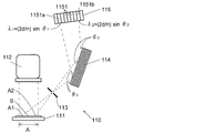
- the X-ray spectroscopic analyzer 110 of the prior application has a sample holder 111 that holds a sample S, an excitation source 112, a slit member 113, a spectral crystal 114, and an X-ray linear sensor 115.
- the sample S may be solid, liquid, or gas, and a sample holder 111 corresponding to the state of the sample is used.
- the excitation source 112 is an X-ray source that irradiates the sample S with X-rays that are excitation light (excitation rays).
- An electron beam source may be used instead of the X-ray source.
- Excitation light is applied to the planar irradiation region A on the sample S by the excitation source 112. Although the excitation light is irradiated perpendicularly to the irradiation region A here, the excitation light may be irradiated at an angle inclined with respect to the irradiation region A.
- the slit member 113 is disposed between the irradiation region A and the spectral crystal 114.
- the spectroscopic crystal 114 a crystal crystal having the smallest crystal plane interval causing Bragg reflection, that is, the crystal plane having the smallest diffraction angle is parallel to the crystal surface.
- this spectroscopic crystal 114 within a small diffraction angle range, only the crystal plane with the smallest crystal plane spacing is used for detection of characteristic X-rays, and characteristic X-rays that are Bragg-reflected on other crystal planes are erroneously detected. To prevent it.
- the longitudinal direction of the opening is parallel to the crystal plane of the spectral crystal 114 used for detection of the irradiation region A and characteristic X-rays (that is, perpendicular to the paper surface in FIG. 1). ) Arranged.
- this crystal plane is referred to as a “predetermined crystal plane”.
- a plurality of linear detection elements 1151 having a length in a direction parallel to the longitudinal direction of the slit (perpendicular to the paper surface of FIG. 1) are arranged in a direction perpendicular to the longitudinal direction of the slit. It is provided.
- Each detection element 1151 only needs to detect the intensity of the X-ray incident thereon, and does not need a function of detecting the wavelength or energy of the incident X-ray.
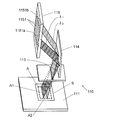
- the X-ray spectroscopic analyzer 110 of the prior application After holding the sample S on the sample holder 111, the irradiation region A of the sample S is irradiated with X-rays as excitation light from the excitation source 112. Thereby, characteristic X-rays having different wavelengths depending on the elements constituting the sample S are emitted from the entire irradiation region A.
- the characteristic X-rays emitted from the irradiation region A are specific 1 on the surface of the spectroscopic crystal 114 and a predetermined crystal plane parallel to the surface in a linear portion parallel to the longitudinal direction of the slit in the irradiation region A. Only characteristic X-rays emitted in an incident direction at two incident angles (90 ⁇ ) ° ( ⁇ is a diffraction angle when the characteristic X-rays are Bragg-reflected by the spectroscopic crystal 114) pass through the slit.
- the linear portions at different positions have different incident angles of characteristic X-rays that pass through the slit and enter the spectroscopic crystal 114. For example, the characteristic X-rays emitted from the linear portion A1 shown in FIGS.
- the characteristic X-ray is incident on the spectral crystal 114 at another incident angle (90- ⁇ 2 ) °.
- the characteristic X-ray diffracted (reflected) by the spectral crystal 114 is detected by one of the detection elements 1151 of the X-ray linear sensor 115.
- the spectroscopic crystal 114 is incident on the spectroscopic crystal 114 at one specific incident angle (90- ⁇ ) ° that differs depending on the linear portion in the irradiation region A. Only characteristic X-rays of one wavelength are incident on the X-ray linear sensor 115 and detected by different detection elements 1151. For example, as for characteristic X-rays emitted from the linear portion A1 shown in FIGS.
- a wavelength that can be measured by a wavelength (specific wavelength) emitted from the linear portion A located at both ends of the irradiation region and diffracted by a predetermined crystal plane of the spectroscopic crystal 114 Since the upper and lower limits of the range are determined, characteristic X-rays with wavelengths outside the range cannot be detected. For this reason, the types of elements that can be analyzed by one apparatus are limited.
- the range of the X-ray linear sensor 115 that the spectroscopic crystal 114 expects is limited, when the position and orientation of the spectroscopic crystal 114 are set for characteristic X-rays having a specific wavelength emitted from the specific linear portion A1, Even if characteristic X-rays of other wavelengths emitted from other linear portions A2 enter the spectroscopic crystal 114 at an angle satisfying the Bragg reflection condition, the diffracted X-rays cannot be detected by the X-ray linear sensor 115. There is a case. Furthermore, the detection sensitivity cannot be increased to measure trace elements, and the wavelength (energy) resolution cannot be increased to perform highly accurate measurement.
- the present inventor configured the X-ray spectroscopic analysis apparatus according to the present invention in order to solve the problem that the X-ray spectroscopic analysis apparatus 110 of the prior application can only perform measurement under predetermined conditions. Examples thereof will be described below. In each embodiment, components similar to those of the X-ray spectroscopic analyzer 110 of the prior application are denoted by similar reference numerals, and description thereof will be omitted as appropriate.
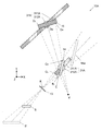
- the X-ray spectroscopic analysis apparatus 10 of Example 1 includes a first rotation mechanism 212 that rotates the spectral crystal 14 and a second rotation mechanism 312 that rotates the X-ray linear sensor 15.
- the first rotation mechanism 212 changes the angle formed by a predetermined crystal plane of the spectral crystal 14.
- the second rotation mechanism 312 has a rotation center in common with the first rotation mechanism 212 and rotates the X-ray linear sensor 15.
- the X-ray linear sensor 15 is rotated 2 ⁇ according to the rotation of ⁇ . That is, the first rotation mechanism 212 and the second rotation mechanism 312 are so-called goniometers.
- the first movement mechanism according to the present invention is constituted by the first rotation mechanism 212
- the second movement mechanism is constituted by the second rotation mechanism 312.
- the first rotation mechanism 212 changes the angle formed by the predetermined crystal plane of the spectroscopic crystal 14 with respect to the surface of the sample S placed on the sample holder 11. Can do. Thereby, among the X-rays emitted from each linear portion in the irradiation region of the sample S, the wavelength of the X-ray satisfying the Bragg reflection condition on the predetermined crystal plane can be changed.
- X-rays having different wavelengths emitted from the same position in the irradiation region of the sample S can be detected, and X-rays having the same wavelength emitted from different positions on the sample surface. Can also be detected. Therefore, the wavelength range of the measurable X-rays is appropriately changed to change the type of measurable element, or the characteristic X-ray intensity of the same element emitted from different positions in the irradiation region of the sample S is changed. Can be measured.
- the X-ray spectroscopic analyzer 10A of the second embodiment also changes the types of measurable elements as appropriate by changing the angle formed by the predetermined crystal plane of the spectroscopic crystal 14 with respect to the surface of the sample S as in the first embodiment.
- the first moving mechanism 21A and the second moving mechanism 31A are different from the first embodiment.
- the first moving mechanism 21A includes a first linear motion mechanism 211A and a first rotating mechanism 212A
- the second moving mechanism 31A includes a second linear motion mechanism 311A and a second rotating mechanism 312A. Respectively.
- the X-ray spectroscopic analyzer 10A of Example 2 is designed based on the following concept. Here, it is assumed that the specifications of the X-ray linear sensor 15 (1280 ch, spacing between detection elements 0.05 mm) are determined in advance.
- FIG. 4 shows the arrangement of each component forming the optical path of the X-rays emitted from the irradiation area A of the sample S in the X-ray spectroscopic analysis apparatus 10A of the second embodiment. In FIG. 4, the description of the sample holder 11 and the irradiation unit 12 is omitted.
- the center wavelength ⁇ M of the measurement range is determined. Based on the center wavelength ⁇ M and the interplanar spacing d of the predetermined crystal plane, the incident angle ⁇ M of X-rays passing through the slit from the sample S and entering the central portion of the spectroscopic crystal 14 is determined based on the Bragg reflection condition. . This determines the direction of a predetermined crystal plane of the spectroscopic crystal 14 (the angle formed with respect to the surface of the sample S).
- the minimum energy E L of the measurement range (the maximum wavelength lambda L)
- the maximum wavelength lambda L the maximum wavelength lambda L
- the optical path length to the sensor 15 is determined.
- the spectroscopic crystal 14 can be arranged at the position of the reference numeral 14a in FIG. The distance from the spectral crystal 14 to the X-ray linear sensor 15 is appropriately changed according to the position of the spectral crystal 14 so that the optical path length does not change.
- the size of the spectral crystal 14 to be used is determined. Thereby, the position of the spectroscopic crystal 14 is determined.
- the wavelength ⁇ satisfying the Bragg reflection condition at one end of the spectroscopic crystal 14 is the shortest wavelength ⁇ H (maximum energy E H ) in this arrangement. It becomes.
- the relative positional relationship between the slit member 13, the spectral crystal 14, and the X-ray linear sensor 15 is determined.
- sample S sample holder 11
- measurement optical system the relative positional relationship between the sample S (sample holder 11) and the measurement optical system is determined.
- position and size of the irradiation area A on the surface of the sample S are determined (refer to reference signs S and S ′ in FIG. 4).
- the results of determining the position of the optical system are shown in the following table.
- the measurement energy range was classified into six.
- the first class of low energy (low 1) is a class that assumes the measurement of characteristic X-rays emitted from V, Cr, Mn, Nd ⁇ Eu, Gd, and the minimum energy E L in the measurement range is 4.9keV.
- the center energy E M X-ray energy of the center wavelength ⁇ M described above
- the maximum energy E H is 6.132 keV
- the energy resolution is 0.937 eV.
- the coordinate position of the center of the X-ray incident surface of the spectral crystal 14 with the center of the irradiation area A of the sample S as the origin (hereinafter referred to as “the coordinate position of the spectral crystal 14”).
- X 219 mm
- Y 139 mm
- the second category of low energy is a category that assumes measurement of characteristic X-rays emitted from Mn, Fe, Co, Ni, Cu, Gd, Td, and Dy to Hf, and has the smallest measurement range.
- the energy E L is 5.98 keV
- the center energy E M is 7.0 keV
- the maximum energy E H is 8.058 keV
- the energy resolution is 1.594 eV.
- the first category (medium 1) of medium energy is a category that assumes the measurement of characteristic X-rays emitted from Ni to As, Se, Ta, W to Pt, Au, and Hg to Pb to At.
- the minimum energy E L is 7.96 keV
- the center energy E M is 9.75 keV
- the maximum energy E H is 11.58 keV
- the energy resolution is 2.797 eV.
- the second class of medium energy (middle 2) is a class that assumes characteristic X-rays emitted from As to Zr, Pb to U to Pu, Am to Es, and the minimum energy E L in the measurement range is 10.48 keV, center energy E M is 13.25 keV, maximum energy E H is 16.06 keV, and energy resolution is 4.328 eV.
- the first category of high energy is a category that assumes the measurement of characteristic X-rays emitted from Nd to Cd, In, Sn, U to Pu, Am to Lr, and the minimum energy E in the measurement range.
- L is 15.88 keV
- center energy E M is 20.75 keV
- maximum energy E H is 25.65 keV
- energy resolution is 7.609 eV.
- the high energy second classification (high 2) is a classification that assumes the measurement of characteristic X-rays emitted from Sb ⁇ Nd ⁇ Eu.
- the minimum energy E L in the measurement range is 25.42 keV
- the center energy E M is 34 keV
- maximum energy E H is 42.60 keV
- energy resolution is 13.406 eV.
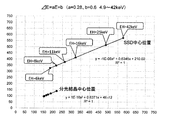
- FIG. 5 is a plot of the center of the spectral crystal 14 and the center position of the X-ray linear sensor 15 based on this result.
- the horizontal axis is the X direction in FIG. 4, and the vertical axis is the Y direction coordinate in FIG. It is. From this graph, it can be seen that the coordinates of the center position of the spectral crystal 14 are located on a straight line. Therefore, it is understood that the spectroscopic crystal 14 may be moved to the coordinate position by the first linear movement mechanism 211A and tilted to a predetermined angle (obtained by the above design) by the first rotation mechanism 212A.
- the spectral crystal 14 is moved to the coordinate position by the second linear motion mechanism 311A, and a predetermined ( It can be seen that it is sufficient to tilt it at an angle (obtained in the above design). As can be seen from the graph of FIG. 5, the center position of the spectroscopic crystal 14 does not need to be moved so much even if the energy ranges are different. Therefore, from the viewpoint of cost reduction, the first moving mechanism 21A may be configured only by the first rotating mechanism 212A.
- the X-ray to be measured has a short wavelength (high energy).
- the resolution decreases. That is, when the first moving mechanism is composed only of the first rotating mechanism 212 and the second moving mechanism is composed only of the second rotating mechanism 312 as in the first embodiment, the optical path length does not change, and thus the characteristic X-ray to be measured. The higher the energy, the lower the wavelength (energy) resolution.
- the X-ray linear sensor 15 is moved to a position farther from the origin as the energy becomes higher (short wavelength), and the optical path length is increased. In the (energy) region, measurement can be performed with higher resolution than in the first embodiment.
- Example 2 an example in which characteristic X-rays with an energy of 5 keV or higher are assumed to be measured has been described. However, the same concept can be used when measuring characteristic X-rays with an energy of less than 5 keV. .
- the types of usable X-ray linear sensors 15 differ between an energy region of 5 keV or more and an energy region of less than 5 keV. In the energy region of 5 keV or more, for example, a silicon strip detector (SSD) is used as the X-ray linear sensor 15, but this cannot be used as it is in an energy region of less than 5 keV. In the energy region below 5 keV, for example, a CCD detector or the like needs to be used as the X-ray linear sensor 15.
- SSD silicon strip detector
- the wavelength range is too wide (the longest wavelength and the shortest wavelength). If you want to detect all X-rays that satisfy the conditions of Bragg reflection with only a single spectroscopic crystal, the ratio of the wavelengths will be about 27 times). . Therefore, in such a case, it is preferable to switch and use a plurality of spectral crystals or artificial multilayer films having different lattice constants as the spectral crystal 14.
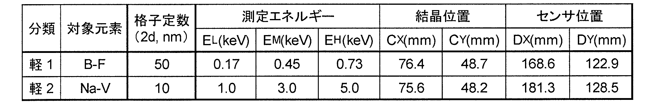
- the table below shows an example of the arrangement of the measurement optical system for measuring B K ⁇ rays (6775 nm, 0.183 keV) to Ti K ⁇ rays (251 nm, 4.932 keV) using two types of spectral crystals with different lattice constants. Show.
- the ultra-low energy first classification (light 1) for light element measurement is an energy classification that assumes the measurement of characteristic X-rays emitted from BF, and the minimum energy E L in the measurement range is 0.17 keV.
- the central energy E M is 0.45 keV, and the maximum energy E H is 0.73 keV.
- the ultra-low energy second classification (light 2) for light element measurement is an energy classification that assumes the measurement of characteristic X-rays emitted from Na to V.
- the minimum energy E L in the measurement range is 1.0 keV
- the central energy E M is 3.0 keV
- the maximum energy E H is 5.0 keV.
- the first moving mechanism 21A can be configured by only the first rotating mechanism 212A.
- the first moving mechanism 21A can also be configured by the first linear motion mechanism 211A and the first rotating mechanism 212A.
- the third embodiment is characterized by the configuration of the slit member 13. Specifically, it is characterized in that the opening width of the slit member 13 is variable.
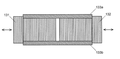
- the opening width of the slit member 13 When the opening width of the slit member 13 is changed, the wavelength (energy) resolution is reduced, but the amount of X-rays diffracted by the spectroscopic crystal 14 through the slit and incident on the X-ray linear sensor 15 increases. Therefore, for example, when measuring trace elements, high-sensitivity measurement is performed by widening the opening width of the slit member 13, and when performing precise analysis, high-resolution measurement is performed by narrowing the opening width of the slit member 13. Can do. For example, as shown in FIG. 6, the sides of a pair of slit plates 131 and 132 are accommodated in linear guide portions 133a and 133b of the main body of the slit member 13, and the linear guide portions 133a and 133b are extended.
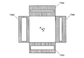
- the slit plates 131 and 132 can be configured to be movable along the direction. As shown in FIG. 4, a plurality of slit members 134a to 134d formed with slits having different opening widths are arranged around the rotation axis R, and the slit members 134a to 134d can be switched by rotating this around the rotation axis R. It can implement by comprising. In the former case, only one of the slit plates may be movable with respect to the other. However, in this case, since the center position of the slit changes, a set of slit plates 131 and 132 is set so as not to change. It is preferable to change the opening width of the slit member 13 by equally moving.
- FIG. 8 shows the results of measuring Mn K ⁇ 1 line under four different conditions (0.1 mm, 0.3 mm, 0.8 mm, 1.6 mm) with different slit widths. Indicates. Moreover, the detection lower limit (LLD) was calculated
- the above equation is a formula for obtaining the lower limit of detection from one standard sample. D is the standard sample concentration (%), Ib is the background intensity (cps), Ip is the signal net intensity (cps), and t is the integration time. (S).
- Fig. 8 (a) shows the measurement results with a slit width of 0.1 mm.
- the full width at half maximum (FWHM) was 4.5 eV, and the detection lower limit (LLD: Lower Limit of Detection) was 0.13%.
- FIG. 8B shows the measurement results with a slit width of 0.3 mm.
- the full width at half maximum (FWHM) was 7.1 eV and the detection lower limit was 0.079%.
- FIG. 8 (c) shows the measurement results with a slit width of 0.8 mm.
- the full width at half maximum (FWHM) was 20 eV and the detection lower limit was 0.049%.
- FIG. 8 (d) shows the measurement results with a slit width of 1.6 mm.
- the full width at half maximum (FWHM) was 32 eV and the detection lower limit was 0.036%.
- measurement according to the purpose of measurement high sensitivity analysis, high resolution analysis
- All the above measurements were performed in an air atmosphere. If the same measurement is performed in a vacuum atmosphere, the lower limit of detection is considered to be lower (that is, the sensitivity is improved).
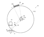
- the modified X-ray spectroscopic analyzer 10C is obtained by adding a specific wavelength measuring optical system 40 for measuring characteristic X-rays emitted from a specific element to the first to third embodiments.
- a specific wavelength measuring optical system included in the modified X-ray spectroscopic analyzer 10C X-rays emitted in various directions from the irradiation region of the sample S are introduced into the solar slit 41 as shown in FIG.
- the solar slit 41 is formed by arranging a plurality of parallel plate-shaped partition plates in parallel, and only light traveling in a direction parallel to the surface of the partition plate passes through the solar slit 41, and thus travels in the parallel direction. Parallel light is extracted. Then, parallel light in which X-rays of various wavelengths are mixed is incident on the concave diffraction grating 42, and only X-rays having wavelengths satisfying the Bragg reflection condition are diffracted. Concentrate on a point.
- characteristic X-rays emitted from a plurality of target elements are measured by any one of the measurement optical systems described in the first to third embodiments, and a sample of a specific element is measured. It is possible to measure the intensity of characteristic X-rays emitted from the entire irradiation region of S and perform quantitative measurement with high accuracy.
- the above-described embodiment is an example, and can be appropriately changed along the gist of the present invention.
- the design concept described in the second embodiment is merely an example, and the arrangement of each component can be determined by another procedure.
- all the detection elements of the X-ray linear sensor 15 are not necessarily used.
- the measurement optical system may be designed so as to always use all the detection elements.
- an X-ray spectroscopic analyzer having the configurations of the first to third embodiments may be configured.
- a plurality of specific wavelength measuring optical systems described in the modification may be provided, and the characteristic X-rays emitted from specific elements may be measured by each.
- the distance from the sample surface to a predetermined crystal plane of the spectroscopic crystal is changed by the first moving mechanism, and the sample is emitted from the irradiation region of the sample.
- the wavelength of the measurement is measured.
- Various parameters of measurement can be changed by appropriately using the first moving mechanism and the second moving mechanism, such as changing (energy) resolution, and the degree of freedom of measurement can be increased.
Abstract
Description
試料表面の所定の照射領域に、特性X線を発生させるための励起線を照射する励起源と、
前記照射領域に面して設けられた分光結晶と、
前記照射領域と前記分光結晶の間に設けられた、該照射領域及び該分光結晶の所定の結晶面に平行なスリットと、
前記スリットの長手方向に垂直な方向に複数の検出素子が並ぶように設けられたX線リニアセンサと
を備えたX線分光分析装置を提案した。 In order to solve the above problems, the applicant of the present application (in Japanese Patent Application No. 2016-237078)
An excitation source for irradiating a predetermined irradiation region on the sample surface with an excitation ray for generating characteristic X-rays;
A spectroscopic crystal provided facing the irradiation region;
A slit parallel to the irradiation region and a predetermined crystal plane of the spectral crystal provided between the irradiation region and the spectral crystal;
An X-ray spectroscopic analysis apparatus including an X-ray linear sensor provided so that a plurality of detection elements are arranged in a direction perpendicular to the longitudinal direction of the slit has been proposed.
a) 試料表面の所定の照射領域に、特性X線を発生させるための励起線を照射する励起源と、
b) 前記照射領域に面して設けられた回折部材と、
c) 前記照射領域と前記回折部材の間に設けられた、該照射領域及び該回折部材の所定の面に平行なスリットを有するスリット部材と、
d) 前記スリットの長手方向に垂直な方向に複数の検出素子が配列されてなる光入射面を有するX線リニアセンサと
e) 前記長手方向に垂直な面内で前記回折部材を移動させることにより、前記試料表面と前記所定の面の成す角度、又は/及び前記試料表面と前記所定の面の間の距離を変更する第1移動機構と、
f) 前記長手方向に垂直な面内で前記X線リニアセンサを移動させることにより、前記スリットを通過して前記所定の面で回折された特性X線の経路上に該X線リニアセンサを位置させる第2移動機構と
を備えることを特徴とする。 In order to achieve the above object, the first aspect of the X-ray spectroscopic analysis apparatus according to the present invention comprises:
a) an excitation source that irradiates a predetermined irradiation region on the sample surface with an excitation ray for generating characteristic X-rays;
b) a diffractive member provided facing the irradiated area;
c) a slit member provided between the irradiation region and the diffraction member, and having a slit parallel to the irradiation region and a predetermined surface of the diffraction member;
d) an X-ray linear sensor having a light incident surface in which a plurality of detection elements are arranged in a direction perpendicular to the longitudinal direction of the slit; and e) by moving the diffractive member in a plane perpendicular to the longitudinal direction. A first moving mechanism that changes an angle formed between the sample surface and the predetermined surface, or / and a distance between the sample surface and the predetermined surface;
f) By moving the X-ray linear sensor in a plane perpendicular to the longitudinal direction, the X-ray linear sensor is positioned on the path of the characteristic X-ray diffracted by the predetermined plane through the slit. And a second moving mechanism.
上記態様のX線分光分析装置では、先願のX線分光分析装置と同様に、液体や粉末のように、位置によらず組成が均一であると見なすことできる試料の測定に好適に用いることができる。上記態様のX線分光分析装置では、後述するように、試料表面の同じ位置から発せられる異なる波長のX線を検出することができ、また試料表面の異なる位置から発せられる同一波長のX線を検出することもできるため、位置によって組成が異なる試料も測定することができる。 The diffraction member is, for example, a spectral crystal or an artificial multilayer film. The predetermined plane is a crystal plane of a spectral crystal or an interface of an artificial multilayer film.
In the X-ray spectroscopic analyzer of the above aspect, like the X-ray spectroscopic analyzer of the previous application, it is preferably used for measuring a sample that can be regarded as having a uniform composition regardless of position, such as a liquid or a powder. Can do. In the X-ray spectrometer of the above aspect, as described later, X-rays having different wavelengths emitted from the same position on the sample surface can be detected, and X-rays having the same wavelength emitted from different positions on the sample surface can be detected. Since it can also detect, the sample from which a composition differs with positions can also be measured.
このX線分光分析装置において、例えば、第1移動機構により、試料表面に対して回折部材の所定の面が成す角度を変化させるとブラッグ反射の条件を満たす波長が変化する。従って、X線の測定波長範囲を適宜に変更して目的の元素から発せられる特性X線を測定することができる。
また、回折部材とX線リニアセンサの相対的な位置関係を固定したまま、第1移動機構により試料表面から回折部材の所定の面までの距離を変化させ、前記照射領域から放出された特性X線がX線リニアセンサに入射する光路長を変更すると、X線リニアセンサの入射面を構成する複数の検出素子にそれぞれ入射するX線の波長幅が変化する。これにより、測定の波長(エネルギー)分解能を変更することができる。
さらに、第2機構により回折部材の所定の面からX線リニアセンサの光入射面までの距離を変化させることによっても測定の波長(エネルギー)分解能を変更することができる。
このように、本発明の第1の態様に係るX線分光分析装置を用いることにより、従来に比べて測定の自由度を高めることができる。 The X-ray spectroscopic analysis apparatus according to the first aspect includes a first moving mechanism that moves a diffractive member that is incident on a characteristic X-ray that is generated in a predetermined irradiation region of a sample surface and passes through a slit; A second movement mechanism is provided for moving an X-ray linear sensor that detects characteristic X-rays diffracted on a plane (such as a crystal plane of a spectral crystal).
In this X-ray spectroscopic analyzer, for example, when the angle formed by the predetermined surface of the diffractive member with respect to the sample surface is changed by the first moving mechanism, the wavelength satisfying the Bragg reflection condition changes. Therefore, characteristic X-rays emitted from the target element can be measured by appropriately changing the measurement wavelength range of X-rays.
In addition, while the relative positional relationship between the diffractive member and the X-ray linear sensor is fixed, the distance from the sample surface to a predetermined surface of the diffractive member is changed by the first moving mechanism, and the characteristic X emitted from the irradiation region is changed. When the optical path length at which the line is incident on the X-ray linear sensor is changed, the wavelength width of the X-ray incident on each of the plurality of detection elements constituting the incident surface of the X-ray linear sensor changes. Thereby, the wavelength (energy) resolution of the measurement can be changed.
Further, the wavelength (energy) resolution of the measurement can be changed by changing the distance from the predetermined surface of the diffractive member to the light incident surface of the X-ray linear sensor by the second mechanism.
Thus, by using the X-ray spectroscopic analyzer according to the first aspect of the present invention, the degree of freedom of measurement can be increased as compared with the conventional case.
a) 試料表面の所定の照射領域に、特性X線を発生させるための励起線を照射する励起源と、
b) 前記照射領域に面して設けられた回折部材と、
c) 前記照射領域と前記回折部材の間に設けられ、該照射領域及び該回折部材の所定の面に平行なスリットを有し、該スリットの開口幅を変更可能な可変スリット部材と
d) 前記スリットを通過し前記所定の面で回折される特性X線の経路上に配置された、前記スリットの長手方向に垂直な方向に複数の検出素子が配列されてなる光入射面を有するX線リニアセンサと
を備えることを特徴とする。 In addition, the second aspect of the X-ray spectroscopic analyzer according to the present invention, which has been made to achieve the above object,
a) an excitation source that irradiates a predetermined irradiation region on the sample surface with an excitation ray for generating characteristic X-rays;
b) a diffractive member provided facing the irradiated area;
c) a variable slit member provided between the irradiation region and the diffractive member, having a slit parallel to the irradiation region and a predetermined surface of the diffractive member, and capable of changing an opening width of the slit; d) An X-ray linear having a light incident surface that is arranged on a path of characteristic X-rays that pass through the slit and is diffracted by the predetermined surface, and in which a plurality of detection elements are arranged in a direction perpendicular to the longitudinal direction of the slit. And a sensor.
試料ホルダ111に試料Sを保持させたうえで、励起源112から試料Sの照射領域Aに励起光であるX線を照射する。これにより、照射領域Aの全体から、試料Sを構成する元素によって異なる波長を有する特性X線が放出される。 The operation of the
After holding the sample S on the

に示すように、開口幅が異なるスリットが形成された複数のスリット部材134a~134dを回転軸Rを中心に配置し、これを回転軸Rを中心に回転させてスリット部材134a~134dを切り換え可能に構成したりすることにより実施することができる。なお、前者の場合、いずれか一方のスリット板のみを他方に対して移動可能としても良いが、その場合スリットの中央の位置が変化するため、これが変化しないよう、1組のスリット板131、132を等分に移動してスリット部材13の開口幅を変更することが好ましい。 When the opening width of the
As shown in FIG. 4, a plurality of
上式は標準試料1個から検出下限値を求める数式であり、Dは標準試料の濃度(%)、Ibはバックグラウンド強度(cps)、Ipは信号のネット強度(cps)、tは積算時間(s)である。 As a measurement example using the X-ray spectroscopic analyzer of Example 3, FIG. 8 shows the results of measuring Mn Kα1 line under four different conditions (0.1 mm, 0.3 mm, 0.8 mm, 1.6 mm) with different slit widths. Indicates. Moreover, the detection lower limit (LLD) was calculated | required by following Formula using the measurement result obtained on each condition.
The above equation is a formula for obtaining the lower limit of detection from one standard sample. D is the standard sample concentration (%), Ib is the background intensity (cps), Ip is the signal net intensity (cps), and t is the integration time. (S).
例えば実施例2で説明した設計思想は一例であって、別の手順で各構成要素の配置を決定していくこともできる。例えば、実施例2では必ずしもX線リニアセンサ15の全検出素子を使用しない構成としたが、必ず全ての検出素子を使用するように測定光学系を設計することもできる。
また、実施例1~3の構成を兼ね備えたX線分光分析装置を構成してもよい。
さらに、変形例で説明した特定波長測定光学系を複数備え、それぞれにより特定の元素から放出される特性X線を測定するようにしても良い。
その他、分光結晶とX線リニアセンサの相対的な位置関係を固定したまま、第1移動機構により試料表面から分光結晶の所定の結晶面までの距離を変化させ、試料の照射領域から放出された特性X線がX線リニアセンサに入射する光路長を変更して、X線リニアセンサの入射面を構成する複数の検出素子にそれぞれ入射するX線の波長幅が変化させることによって、測定の波長(エネルギー)分解能を変更する等、第1移動機構及び第2移動機構を適宜に用いて様々な測定のパラメータを変更し、測定の自由度を高めるでことができる。 The above-described embodiment is an example, and can be appropriately changed along the gist of the present invention.
For example, the design concept described in the second embodiment is merely an example, and the arrangement of each component can be determined by another procedure. For example, in the second embodiment, all the detection elements of the X-ray
Further, an X-ray spectroscopic analyzer having the configurations of the first to third embodiments may be configured.
Furthermore, a plurality of specific wavelength measuring optical systems described in the modification may be provided, and the characteristic X-rays emitted from specific elements may be measured by each.
In addition, while the relative positional relationship between the spectroscopic crystal and the X-ray linear sensor is fixed, the distance from the sample surface to a predetermined crystal plane of the spectroscopic crystal is changed by the first moving mechanism, and the sample is emitted from the irradiation region of the sample. By changing the optical path length of the characteristic X-rays incident on the X-ray linear sensor and changing the wavelength widths of the X-rays incident on the plurality of detection elements constituting the incident surface of the X-ray linear sensor, the wavelength of the measurement is measured. Various parameters of measurement can be changed by appropriately using the first moving mechanism and the second moving mechanism, such as changing (energy) resolution, and the degree of freedom of measurement can be increased.
11…試料ホルダ
12…照射部
13…スリット部材
131…スリット板
133a、133b…リニアガイド部
134a~134d…スリット部材
14…分光結晶
15…X線リニアセンサ
21、21A…第1移動機構
211A…第1直動機構
212、212A…第1回転機構
31、31A…第2移動機構
311A…第2直動機構
312、312A…第2回転機構
40…特定波長測定光学系
41…ソーラースリット
42…凹面回折格子
43…X線検出器 DESCRIPTION OF
Claims (12)
- a) 試料表面の所定の照射領域に、特性X線を発生させるための励起線を照射する励起源と、
b) 前記照射領域に面して設けられた回折部材と、
c) 前記照射領域と前記回折部材の間に設けられた、該照射領域及び該回折部材の所定の面に平行なスリットを有するスリット部材と、
d) 前記スリットの長手方向に垂直な方向に複数の検出素子が配列されてなる光入射面を有するX線リニアセンサと
e) 前記長手方向に垂直な面内で前記回折部材を移動させることにより、前記試料表面と前記所定の面の成す角度、又は/及び前記試料表面と前記所定の面の間の距離を変更する第1移動機構と、
f) 前記長手方向に垂直な面内で前記X線リニアセンサを移動させることにより、前記スリットを通過して前記所定の面で回折された特性X線の経路上に該X線リニアセンサを位置させる第2移動機構と
を備えることを特徴とするX線分光分析装置。 a) an excitation source that irradiates a predetermined irradiation region on the sample surface with an excitation ray for generating characteristic X-rays;
b) a diffractive member provided facing the irradiated area;
c) a slit member provided between the irradiation region and the diffraction member, and having a slit parallel to the irradiation region and a predetermined surface of the diffraction member;
d) an X-ray linear sensor having a light incident surface in which a plurality of detection elements are arranged in a direction perpendicular to the longitudinal direction of the slit; and e) by moving the diffractive member in a plane perpendicular to the longitudinal direction. A first moving mechanism that changes an angle formed between the sample surface and the predetermined surface, or / and a distance between the sample surface and the predetermined surface;
f) By moving the X-ray linear sensor in a plane perpendicular to the longitudinal direction, the X-ray linear sensor is positioned on the path of the characteristic X-ray diffracted by the predetermined plane through the slit. An X-ray spectroscopic analyzer, comprising: a second moving mechanism that causes - 前記第1移動機構が回転機構及び直動機構を備えることを特徴とする請求項1に記載のX線分光分析装置。 The X-ray spectroscopic analysis apparatus according to claim 1, wherein the first movement mechanism includes a rotation mechanism and a linear movement mechanism.
- 前記第2移動機構が回転機構及び直動機構を備えることを特徴とする請求項1に記載のX線分光分析装置。 The X-ray spectroscopic analysis apparatus according to claim 1, wherein the second movement mechanism includes a rotation mechanism and a linear movement mechanism.
- 前記回折部材が、切り換え可能に配置された、回折可能なX線の波長範囲が異なる複数の回折部材の中から選択されることを特徴とする請求項1に記載のX線分光分析装置。 2. The X-ray spectroscopic analyzer according to claim 1, wherein the diffractive member is selected from a plurality of diffractive members arranged in a switchable manner and having different diffractable X-ray wavelength ranges.
- 前記X線リニアセンサが、切り換え可能に配置された、検出可能なX線の波長範囲が異なる複数のX線リニアセンサの中から選択されることを特徴とする請求項1に記載のX線分光分析装置。 2. The X-ray spectroscopy according to claim 1, wherein the X-ray linear sensor is selected from a plurality of X-ray linear sensors arranged in a switchable manner and having different detectable X-ray wavelength ranges. Analysis equipment.
- 前記X線リニアセンサが、検出素子が長手方向に垂直な方向と該方向に直交する方向に二次元的に配列されたものであって、前記直交する方向に配置された検出素子の出力信号が1つの出力信号として出力されるものであることを特徴とする請求項1に記載のX線分光分析装置。 In the X-ray linear sensor, the detection elements are two-dimensionally arranged in a direction perpendicular to the longitudinal direction and a direction orthogonal to the direction, and an output signal of the detection element arranged in the orthogonal direction is The X-ray spectroscopic analysis apparatus according to claim 1, wherein the X-ray spectroscopy analysis apparatus is output as one output signal.
- a) 試料表面の所定の照射領域に、特性X線を発生させるための励起線を照射する励起源と、
b) 前記照射領域に面して設けられた回折部材と、
c) 前記照射領域と前記回折部材の間に設けられ、該照射領域及び該回折部材の所定の面に平行なスリットを有し、該スリットの開口幅を変更可能な可変スリット部材と
d) 前記スリットを通過し前記所定の面で回折される特性X線の経路上に配置された、前記スリットの長手方向に垂直な方向に複数の検出素子が配列されてなる光入射面を有するX線リニアセンサと
を備えることを特徴とするX線分光分析装置。 a) an excitation source that irradiates a predetermined irradiation region on the sample surface with an excitation ray for generating characteristic X-rays;
b) a diffractive member provided facing the irradiated area;
c) a variable slit member provided between the irradiation region and the diffractive member, having a slit parallel to the irradiation region and a predetermined surface of the diffractive member, and capable of changing an opening width of the slit; d) An X-ray linear having a light incident surface that is arranged on a path of characteristic X-rays that pass through the slit and is diffracted by the predetermined surface, and in which a plurality of detection elements are arranged in a direction perpendicular to the longitudinal direction of the slit. An X-ray spectroscopic analyzer comprising: a sensor. - 前記可変スリット部材が、一辺が対向配置された2枚のスリット板のうちの少なくとも一方を他方に対して相対的に移動することによりスリットの開口幅を変更する機構を有することを特徴とする請求項7に記載のX線分光分析装置。 The variable slit member has a mechanism for changing the opening width of the slit by moving at least one of the two slit plates arranged opposite to each other relative to the other. Item 8. The X-ray spectroscopy analyzer according to Item 7.
- 前記可変スリット部材が、スリットの開口幅が異なる複数のスリット部材が切り換え可能に構成されたものであることを特徴とする請求項7に記載のX線分光分析装置。 The X-ray spectroscopic analyzer according to claim 7, wherein the variable slit member is configured such that a plurality of slit members having different slit opening widths can be switched.
- 回折条件が異なる複数の回折部材を切り換え可能に備えることを特徴とする請求項7に記載のX線分光分析装置。 The X-ray spectroscopic analyzer according to claim 7, wherein a plurality of diffraction members having different diffraction conditions are switchably provided.
- 検出波長が異なる複数のX線リニアセンサを切り替え可能に備えることを特徴とする請求項7に記載のX線分光分析装置。 The X-ray spectroscopic analyzer according to claim 7, wherein a plurality of X-ray linear sensors having different detection wavelengths are provided so as to be switchable.
- さらに、
e) 前記照射領域から放出されるX線のうち、特定の方向に進むX線のみを通過させる平行光スリット部材と、
f) 前記平行光スリット部材を通過した、前記特定の方向に進むX線のうち、特定の波長を有する光を回折して集光する凹面回折部材と、
g) 前記所定の面に受光面が位置するように配置されたX線検出器と
を備えることを特徴とする請求項1又は7に記載のX線分光分析装置。 further,
e) a parallel light slit member that allows only X-rays traveling in a specific direction among X-rays emitted from the irradiation region;
f) a concave diffraction member that diffracts and collects light having a specific wavelength among the X-rays that have passed through the parallel light slit member and proceed in the specific direction;
The X-ray spectrometer according to claim 1, further comprising: an X-ray detector disposed so that a light receiving surface is positioned on the predetermined surface.
Priority Applications (6)
| Application Number | Priority Date | Filing Date | Title |
|---|---|---|---|
| US16/612,092 US11112371B2 (en) | 2017-05-18 | 2017-05-18 | X-ray spectrometer |
| CN201780090533.5A CN110678743B (en) | 2017-05-18 | 2017-05-18 | X-ray spectroscopic analyzer |
| EP17909827.2A EP3627146A4 (en) | 2017-05-18 | 2017-05-18 | X-ray spectrometer |
| JP2019518701A JP6874835B2 (en) | 2017-05-18 | 2017-05-18 | X-ray spectroscopic analyzer |
| PCT/JP2017/018701 WO2018211664A1 (en) | 2017-05-18 | 2017-05-18 | X-ray spectrometer |
| KR1020197034353A KR20200002951A (en) | 2017-05-18 | 2017-05-18 | X-ray spectroscopy device |
Applications Claiming Priority (1)
| Application Number | Priority Date | Filing Date | Title |
|---|---|---|---|
| PCT/JP2017/018701 WO2018211664A1 (en) | 2017-05-18 | 2017-05-18 | X-ray spectrometer |
Publications (1)
| Publication Number | Publication Date |
|---|---|
| WO2018211664A1 true WO2018211664A1 (en) | 2018-11-22 |
Family
ID=64273507
Family Applications (1)
| Application Number | Title | Priority Date | Filing Date |
|---|---|---|---|
| PCT/JP2017/018701 WO2018211664A1 (en) | 2017-05-18 | 2017-05-18 | X-ray spectrometer |
Country Status (6)
| Country | Link |
|---|---|
| US (1) | US11112371B2 (en) |
| EP (1) | EP3627146A4 (en) |
| JP (1) | JP6874835B2 (en) |
| KR (1) | KR20200002951A (en) |
| CN (1) | CN110678743B (en) |
| WO (1) | WO2018211664A1 (en) |
Cited By (2)
| Publication number | Priority date | Publication date | Assignee | Title |
|---|---|---|---|---|
| US11137360B2 (en) | 2017-09-27 | 2021-10-05 | Shimadzu Corporation | X-ray spectrometer and chemical state analysis method using the same |
| WO2023017636A1 (en) * | 2021-08-10 | 2023-02-16 | 株式会社島津製作所 | X-ray analysis device |
Families Citing this family (13)
| Publication number | Priority date | Publication date | Assignee | Title |
|---|---|---|---|---|
| US10295485B2 (en) | 2013-12-05 | 2019-05-21 | Sigray, Inc. | X-ray transmission spectrometer system |
| EP3627146A4 (en) | 2017-05-18 | 2020-05-13 | Shimadzu Corporation | X-ray spectrometer |
| US10989822B2 (en) | 2018-06-04 | 2021-04-27 | Sigray, Inc. | Wavelength dispersive x-ray spectrometer |
| US10658145B2 (en) | 2018-07-26 | 2020-05-19 | Sigray, Inc. | High brightness x-ray reflection source |
| WO2020051221A2 (en) | 2018-09-07 | 2020-03-12 | Sigray, Inc. | System and method for depth-selectable x-ray analysis |
| US11143605B2 (en) | 2019-09-03 | 2021-10-12 | Sigray, Inc. | System and method for computed laminography x-ray fluorescence imaging |
| US11175243B1 (en) | 2020-02-06 | 2021-11-16 | Sigray, Inc. | X-ray dark-field in-line inspection for semiconductor samples |
| JP7144475B2 (en) * | 2020-03-30 | 2022-09-29 | 日本電子株式会社 | Analysis method and analyzer |
| US11215572B2 (en) | 2020-05-18 | 2022-01-04 | Sigray, Inc. | System and method for x-ray absorption spectroscopy using a crystal analyzer and a plurality of detector elements |
| JP7380421B2 (en) * | 2020-05-27 | 2023-11-15 | 株式会社島津製作所 | X-ray analysis device and X-ray analysis method |
| DE112021004828T5 (en) | 2020-09-17 | 2023-08-03 | Sigray, Inc. | SYSTEM AND PROCEDURE USING X-RAYS FOR DEPTH RESOLUTION MEASUREMENT AND ANALYSIS |
| KR20230109735A (en) | 2020-12-07 | 2023-07-20 | 시그레이, 아이엔씨. | High-throughput 3D x-ray imaging system using transmitted x-ray source |
| US11885755B2 (en) | 2022-05-02 | 2024-01-30 | Sigray, Inc. | X-ray sequential array wavelength dispersive spectrometer |
Citations (9)
| Publication number | Priority date | Publication date | Assignee | Title |
|---|---|---|---|---|
| JPS5788354A (en) * | 1980-11-21 | 1982-06-02 | Shimadzu Corp | X-ray analysing apparatus |
| JPH0382943A (en) * | 1989-08-25 | 1991-04-08 | Nec Corp | Total reflection fluorescent x-ray analyzing apparatus |
| JP2002189004A (en) | 2000-12-21 | 2002-07-05 | Jeol Ltd | X-ray analyzer |
| JP2002214165A (en) * | 2001-01-17 | 2002-07-31 | Japan Science & Technology Corp | Fluorescent x-ray spectroscopic method and device |
| JP2002214167A (en) * | 1998-10-30 | 2002-07-31 | Rigaku Industrial Co | Fluorescent x-ray analyzer |
| JP2003098126A (en) * | 2001-09-26 | 2003-04-03 | Rigaku Industrial Co | X-ray analyzer for having fluorescence and diffraction for common use |
| JP2008309742A (en) * | 2007-06-18 | 2008-12-25 | Shimadzu Corp | Fluorescent x-ray analyzer |
| JP2013096750A (en) | 2011-10-28 | 2013-05-20 | Hamamatsu Photonics Kk | X-ray spectral detection device |
| WO2016103834A1 (en) * | 2014-12-25 | 2016-06-30 | 株式会社リガク | Oblique-incidence x-ray fluorescence analysis device and method |
Family Cites Families (19)
| Publication number | Priority date | Publication date | Assignee | Title |
|---|---|---|---|---|
| DE1472229B2 (en) | 1965-12-23 | 1970-05-27 | Siemens AG, 1000 Berlin u. 8000 München | X-ray spectrometer additional device for a particle beam device, in particular an electron microscope |
| US3663812A (en) | 1969-02-27 | 1972-05-16 | Mc Donnell Douglas Corp | X-ray spectrographic means having fixed analyzing and detecting means |
| US4362935A (en) | 1979-02-09 | 1982-12-07 | Martin Marietta Corporation | Field portable element analysis unit |
| SU868503A1 (en) | 1980-01-29 | 1981-09-30 | Предприятие П/Я М-5912 | X-ray spectrometer |
| FI873627A (en) * | 1987-08-25 | 1989-02-22 | Leningradskoe Nauchno-Proizvodstvennoe Obiedinenie/Çburevestnikç | FLERKANALSROENTGENSPEKTROMETER. |
| GB9223592D0 (en) * | 1992-11-11 | 1992-12-23 | Fisons Plc | X-ray analysis apparatus |
| WO1997013142A1 (en) * | 1995-10-03 | 1997-04-10 | Philips Electronics N.V. | Apparatus for simultaneous x-ray diffraction and x-ray fluorescence measurements |
| DE19603000A1 (en) | 1996-01-27 | 1997-07-31 | Philips Patentverwaltung | Calibration method for computer-controlled X=ray spectroscope |
| JP3511826B2 (en) * | 1997-01-23 | 2004-03-29 | 株式会社島津製作所 | X-ray fluorescence analyzer |
| JP5320807B2 (en) | 2008-04-25 | 2013-10-23 | 株式会社島津製作所 | Wavelength dispersive X-ray spectrometer |
| CN102472714B (en) * | 2009-07-01 | 2014-08-13 | 株式会社理学 | X-ray apparatus, method of using the same and x-ray irradiation method |
| JP6009963B2 (en) * | 2013-02-14 | 2016-10-19 | 日本電子株式会社 | Sample analysis method and sample analyzer |
| JP2014209098A (en) | 2013-03-25 | 2014-11-06 | 株式会社リガク | X-ray analyzer |
| DE102013207160A1 (en) | 2013-04-19 | 2014-10-23 | Helmholtz-Zentrum Berlin Für Materialien Und Energie Gmbh | Apparatus and method for determining the energetic composition of electromagnetic waves |
| DE102016014213A1 (en) | 2015-12-08 | 2017-07-06 | Shimadzu Corporation | X-RAY SPECTROSCOPIC ANALYSIS DEVICE AND ELEMENTARY ANALYSIS METHOD |
| EP3627146A4 (en) | 2017-05-18 | 2020-05-13 | Shimadzu Corporation | X-ray spectrometer |
| WO2019064360A1 (en) | 2017-09-27 | 2019-04-04 | 株式会社島津製作所 | X-ray spectroscopic analysis device and chemical state analysis device using said x-ray spectroscopic analysis device |
| JP6860116B2 (en) | 2018-02-21 | 2021-04-14 | 株式会社島津製作所 | Chemical state analyzer and method for battery materials |
| JP2021012054A (en) | 2019-07-04 | 2021-02-04 | 日本電子株式会社 | Fluorescent x-ray analyzer and method for calibrating the same |
-
2017
- 2017-05-18 EP EP17909827.2A patent/EP3627146A4/en not_active Withdrawn
- 2017-05-18 JP JP2019518701A patent/JP6874835B2/en active Active
- 2017-05-18 WO PCT/JP2017/018701 patent/WO2018211664A1/en unknown
- 2017-05-18 CN CN201780090533.5A patent/CN110678743B/en active Active
- 2017-05-18 KR KR1020197034353A patent/KR20200002951A/en not_active Application Discontinuation
- 2017-05-18 US US16/612,092 patent/US11112371B2/en active Active
Patent Citations (9)
| Publication number | Priority date | Publication date | Assignee | Title |
|---|---|---|---|---|
| JPS5788354A (en) * | 1980-11-21 | 1982-06-02 | Shimadzu Corp | X-ray analysing apparatus |
| JPH0382943A (en) * | 1989-08-25 | 1991-04-08 | Nec Corp | Total reflection fluorescent x-ray analyzing apparatus |
| JP2002214167A (en) * | 1998-10-30 | 2002-07-31 | Rigaku Industrial Co | Fluorescent x-ray analyzer |
| JP2002189004A (en) | 2000-12-21 | 2002-07-05 | Jeol Ltd | X-ray analyzer |
| JP2002214165A (en) * | 2001-01-17 | 2002-07-31 | Japan Science & Technology Corp | Fluorescent x-ray spectroscopic method and device |
| JP2003098126A (en) * | 2001-09-26 | 2003-04-03 | Rigaku Industrial Co | X-ray analyzer for having fluorescence and diffraction for common use |
| JP2008309742A (en) * | 2007-06-18 | 2008-12-25 | Shimadzu Corp | Fluorescent x-ray analyzer |
| JP2013096750A (en) | 2011-10-28 | 2013-05-20 | Hamamatsu Photonics Kk | X-ray spectral detection device |
| WO2016103834A1 (en) * | 2014-12-25 | 2016-06-30 | 株式会社リガク | Oblique-incidence x-ray fluorescence analysis device and method |
Non-Patent Citations (4)
Cited By (2)
| Publication number | Priority date | Publication date | Assignee | Title |
|---|---|---|---|---|
| US11137360B2 (en) | 2017-09-27 | 2021-10-05 | Shimadzu Corporation | X-ray spectrometer and chemical state analysis method using the same |
| WO2023017636A1 (en) * | 2021-08-10 | 2023-02-16 | 株式会社島津製作所 | X-ray analysis device |
Also Published As
| Publication number | Publication date |
|---|---|
| JP6874835B2 (en) | 2021-05-19 |
| CN110678743A (en) | 2020-01-10 |
| JPWO2018211664A1 (en) | 2019-11-07 |
| CN110678743B (en) | 2022-06-24 |
| US20200225172A1 (en) | 2020-07-16 |
| EP3627146A1 (en) | 2020-03-25 |
| US11112371B2 (en) | 2021-09-07 |
| EP3627146A4 (en) | 2020-05-13 |
| KR20200002951A (en) | 2020-01-08 |
Similar Documents
| Publication | Publication Date | Title |
|---|---|---|
| WO2018211664A1 (en) | X-ray spectrometer | |
| CN111133302B (en) | X-ray spectroscopic analyzer and chemical state analysis method using the same | |
| US5497008A (en) | Use of a Kumakhov lens in analytic instruments | |
| JP6673172B2 (en) | X-ray spectrometer and elemental analysis method | |
| US6697454B1 (en) | X-ray analytical techniques applied to combinatorial library screening | |
| Schlesiger et al. | XAFS spectroscopy by an X-ray tube based spectrometer using a novel type of HOPG mosaic crystal and optimized image processing | |
| EP2772752B1 (en) | X-ray spectrometry detector device | |
| US20110268251A1 (en) | Method and apparatus for using an area x-ray detector as a point detector in an x-ray diffractometer | |
| US9417341B2 (en) | Device and method for determining the energetic composition of electromagnetic waves | |
| JP4715345B2 (en) | X-ray analyzer | |
| JP2002189004A (en) | X-ray analyzer | |
| US6487269B2 (en) | Apparatus for analysing a sample | |
| JP6009156B2 (en) | Diffractometer | |
| Brügemann et al. | Detectors for X-ray diffraction and scattering: a user's overview | |
| Holfelder et al. | A double crystal von Hamos spectrometer for traceable x-ray emission spectroscopy | |
| WO2017169247A1 (en) | X-ray fluorescence analyzer and x-ray fluorescence analysis method | |
| US20230296536A1 (en) | Parallel plate x-ray collimator having a variable acceptance angle and an x-ray analysis apparatus | |
| WO2003081222A1 (en) | Screening of combinatorial library using x-ray analysis | |
| JP6862710B2 (en) | X-ray diffractometer | |
| SU609080A1 (en) | Device for dispersionless x-ray fluorescent analysis | |
| JPH11502312A (en) | X-ray analyzer including rotatable primary collimator | |
| JP2023107744A (en) | Method and system for simultaneously executing x-ray absorption spectroscopy and fluorescent x-ray spectroscopic analysis | |
| KR20150118228A (en) | Parallel beam optic device for X-ray | |
| SU202571A1 (en) | X-RAY MICRO ANALYZER | |
| JPH0434349A (en) | X-ray fluorescence analyzer |
Legal Events
| Date | Code | Title | Description |
|---|---|---|---|
| 121 | Ep: the epo has been informed by wipo that ep was designated in this application |
Ref document number: 17909827 Country of ref document: EP Kind code of ref document: A1 |
|
| ENP | Entry into the national phase |
Ref document number: 2019518701 Country of ref document: JP Kind code of ref document: A |
|
| NENP | Non-entry into the national phase |
Ref country code: DE |
|
| ENP | Entry into the national phase |
Ref document number: 20197034353 Country of ref document: KR Kind code of ref document: A |
|
| ENP | Entry into the national phase |
Ref document number: 2017909827 Country of ref document: EP Effective date: 20191218 |