WO2018207498A1 - 穿刺ロボット及び穿刺制御用プログラム - Google Patents
穿刺ロボット及び穿刺制御用プログラム Download PDFInfo
- Publication number
- WO2018207498A1 WO2018207498A1 PCT/JP2018/013938 JP2018013938W WO2018207498A1 WO 2018207498 A1 WO2018207498 A1 WO 2018207498A1 JP 2018013938 W JP2018013938 W JP 2018013938W WO 2018207498 A1 WO2018207498 A1 WO 2018207498A1
- Authority
- WO
- WIPO (PCT)
- Prior art keywords
- puncture
- puncture needle
- needle
- arm
- robot
- Prior art date
- Legal status (The legal status is an assumption and is not a legal conclusion. Google has not performed a legal analysis and makes no representation as to the accuracy of the status listed.)
- Ceased
Links
Images

Classifications
-
- A—HUMAN NECESSITIES
- A61—MEDICAL OR VETERINARY SCIENCE; HYGIENE
- A61B—DIAGNOSIS; SURGERY; IDENTIFICATION
- A61B17/00—Surgical instruments, devices or methods
- A61B17/34—Trocars; Puncturing needles
-
- A—HUMAN NECESSITIES
- A61—MEDICAL OR VETERINARY SCIENCE; HYGIENE
- A61B—DIAGNOSIS; SURGERY; IDENTIFICATION
- A61B34/00—Computer-aided surgery; Manipulators or robots specially adapted for use in surgery
- A61B34/30—Surgical robots
- A61B34/32—Surgical robots operating autonomously
-
- A—HUMAN NECESSITIES
- A61—MEDICAL OR VETERINARY SCIENCE; HYGIENE
- A61B—DIAGNOSIS; SURGERY; IDENTIFICATION
- A61B34/00—Computer-aided surgery; Manipulators or robots specially adapted for use in surgery
- A61B34/30—Surgical robots
- A61B34/35—Surgical robots for telesurgery
-
- B—PERFORMING OPERATIONS; TRANSPORTING
- B25—HAND TOOLS; PORTABLE POWER-DRIVEN TOOLS; MANIPULATORS
- B25J—MANIPULATORS; CHAMBERS PROVIDED WITH MANIPULATION DEVICES
- B25J13/00—Controls for manipulators
- B25J13/08—Controls for manipulators by means of sensing devices, e.g. viewing or touching devices
Definitions
- the present invention relates to a puncture robot and a puncture control program, and more particularly to a puncture robot that punctures a patient with a puncture needle by remote control, and reliably punctures a puncture target by suppressing deflection generated in the puncture needle.
- the present invention relates to a puncture robot and a puncture control program.
- the present inventors have developed a puncture robot that is used when a puncture needle is punctured into a lesion such as a tumor of a patient under fluoroscopy by CT (Computed Tomography).
- a puncture needle is attached to the tip of a relatively long arm, and an appropriate parallel movement operation or rotation operation is performed on the arm. Is positioned on the puncture route, and puncture is performed by moving the puncture needle along the puncture route (see, for example, Patent Document 1).
- the puncture path is an imaginary line passing through the center of the affected part such as a tumor that is the target of puncture, and the insertion length when the puncture needle is inserted while avoiding bones and main organs can be as long as possible. It is a virtual line that shortens.
- the puncture needle bends immediately before being stabbed into the body. Since the puncture needle will enter the body, the puncture point where the puncture needle enters the body will deviate from the expected puncture point, and the puncture needle will bend. It turned out that it was shifted from the puncture route by being stabbed in the state.
- the puncture accuracy with respect to the target can be improved by eliminating the deflection of the puncture needle.
- the force that causes the puncture needle to bend is a reaction force that acts on the puncture needle when the patient is punctured with the puncture needle, and the direction and magnitude of this reaction force is attached to the puncture needle. It was found that it could be detected by a force sensor provided on the arm.
- This force sensor is originally provided as a safety device, in order to detect the occurrence of some abnormality when the puncture needle is punctured into the patient, and to start a crisis avoiding operation such as an emergency stop. It is what is used for.
- the puncture robot of the present invention includes a puncture needle that punctures a puncture target in a patient's body, an arm that has a needle support portion that detachably supports the proximal end of the puncture needle, and a through-arm.
- the arm is provided with a force sensor that detects a force acting on the puncture needle, and the adjustment mechanism At the time of puncturing, the force detected by the force sensor is eliminated by adjusting the position and inclination of the puncture needle.
- the position and inclination of the puncture needle are adjusted by the adjustment mechanism, and the puncture needle is punctured on the extension line of the virtual line connecting the puncture point on the body surface and the puncture target when the puncture needle punctures the patient. It is also characterized in that the force detected by the force sensor is eliminated by positioning the proximal end of the needle.
- the puncture control program controls the position and inclination of the puncture needle whose base end is detachably supported at the distal end of the arm, and moves the puncture needle directly in the extending direction of the puncture needle.
- a puncture control program for a puncture robot that punctures a puncture target in a patient's body, the step of detecting the force acting on the puncture needle with a force sensor provided on the arm, and the deflection generated in the puncture needle by the detected force Estimating the position of the puncture point on the body surface when the puncture needle punctures the patient, the position of the proximal end of the puncture needle that is on the extension line of the virtual line connecting the puncture point and the puncture target, and The step of specifying the inclination of the puncture needle and the step of setting the proximal end of the puncture needle to the specified position and setting the puncture needle to the specified inclination are included.
- the puncture accuracy of the puncture target can be improved by performing the puncture while eliminating the deflection generated in the puncture needle by the patient's puncture with the puncture needle.
- the puncture model of the puncture needle assumed in the present invention will be described.
- the puncture needle acts with a concentrated load at the puncture point to the patient. That is, the model was set as shown in FIG. 1 on the assumption that the model of a cantilever beam subjected to concentrated load can be used.
- the sectional moment I [mm 4 ] of the puncture needle and the displacement ⁇ [mm] due to the deflection of the puncture needle can be expressed by the following equations.
- E is the Young's modulus [MPa] of the puncture needle
- d is the diameter [mm] of the cross section of the puncture needle.
- the remaining puncture amount l rem [mm] can be expressed by the following equation using the planned puncture depth l punc [mm] and the length l in [mm] of the puncture needle inserted.
- the puncture point of the puncture needle as to position the proximal end of the puncture needle on the extension of the virtual line connecting the puncturing target, when the coordinates (y *, z *), the value of the coordinates can be expressed by the following equation.
- ⁇ * A is the inclination of the target posture. If ⁇ A is the target rotation angle, the target rotation angle ⁇ A and the target posture inclination ⁇ * A can be expressed by the following equations.
- the coordinate value of the puncture target (y t , z t ) can be expressed by the following equation.
- the coordinates (y * , z * ) of the proximal end of the puncture needle and the inclination ⁇ * A can be obtained.
- the obtained (y * , z * , ⁇ * A ) as the position of the proximal end of the puncture needle and the inclination of the puncture needle, the bending of the puncture needle can be eliminated. Puncture accuracy can be improved.
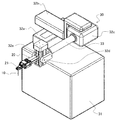
- the puncture robot according to the present invention includes an arm 20 having a needle support portion 21 at its distal end that detachably supports the proximal end of the puncture needle 10, and the position of the puncture needle 10 via the arm 20. And a main body 30 provided with an adjusting mechanism for adjusting the inclination.
- the main body 30 has a rectangular base 31, and a first parallel movement mechanism 32 a that controls parallel movement in the first horizontal direction is provided on the upper surface of the base 31.
- a second translation mechanism 32b for controlling translation in a second horizontal direction perpendicular to the first horizontal direction is provided.
- a first rotation mechanism 32c having a rotation rod 33 extended in parallel with the first horizontal direction is provided at the tip of the second parallel movement mechanism 32b, and the rotation rod around the central axis of the rotation rod 33 is provided. 33 is controlled to rotate.
- a second turning mechanism 32d to which an advance / retreat mechanism 32e is attached via a rotating shaft (not shown) orthogonal to the extending direction of the turning rod 33 is provided at the tip of the turning rod 33.
- the tilt of the puncture needle 10 can be freely controlled by the mechanism 32d and the first rotation mechanism 32c.
- the advance / retreat mechanism 32e controls the advance / retreat of the puncture needle 10 along the extending direction by moving the arm 20 attached to the proximal end side of the advance / retreat mechanism 32e in the extending direction of the puncture needle 10.
- an elevating mechanism for elevating and lowering the first parallel movement mechanism 32a in the vertical direction is provided in the base 31, and the puncture needle 10 is controlled by controlling these six degrees of freedom. It is possible to freely control the position and inclination of the.
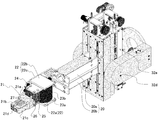
- the arm 20 includes a first arm 20a and a second arm 20b, and the first arm 20a and the second arm 20b constitute a parallel link, whereby the advance / retreat mechanism 32e.
- the advancing / retreating direction is parallel to the extending direction of the puncture needle 10. Therefore, the puncture needle 10 can be linearly moved along the extending direction by controlling the advance / retreat mechanism 32e.
- the leading ends of the first arm 20a and the second arm 20b are rotatably attached to the rectangular frame 22.
- the rectangular frame 22 includes a bottom wall 22a, a ceiling wall 22b facing the bottom wall 22a, a first side wall 22c and a second side wall (not shown) installed on the bottom wall 22a and the ceiling wall 22b.
- the first side wall 22c and the second side wall are rotatably mounted on the tip side of the first arm 20a and the second arm 20b.
- the first force sensor 23a and the second force sensor 23b are stacked on the upper surface of the bottom wall 22a.
- the reason why the two force sensors 23a and 23b are provided is for fail-safe use when one of the force sensors fails.
- a support piece 24 extending in the extending direction of the first arm 20a and the second arm 20b is provided on the upper surface of the second force sensor 23b, and an air cylinder 25 is mounted on the lower surface of the support piece 24.
- This air cylinder 25 has a rod (not shown) that advances and retracts the puncture needle 10 in parallel with the extending direction, and directly moves the puncture needle 10 at a speed faster than the drive speed of the advance / retreat mechanism 32e. The patient's skin is easy to puncture.
- the rod of the air cylinder 25 is provided with a connecting body 26 for fixedly mounting the needle support portion 21.
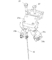
- the needle support portion 21 is connected via two fixing pins 27 as shown in FIGS. It is supposed to be fixedly attached to the connecting body 26.
- a first needle gripping arm 21b and a second needle gripping arm 21c are rotatably provided on the distal end side of the base 21a of the needle support portion 21, and the first needle gripping arm 21b and The proximal end of the puncture needle 10 is gripped by the second needle gripping arm 21c.
- the first needle gripping arm 21b and the second needle gripping arm 21c are integrally connected by a snap lock 21d after gripping the puncture needle 10, so that the puncture needle 10 can be firmly supported.
- the puncture robot of the present invention can be remotely operated using a controller (not shown), and the controller adjusts the puncture robot with the controller while confirming the puncture target under X-ray transmission for a patient sleeping on a CT bed. By operating, the puncture needle 10 is positioned on the puncture route.
- the advancement / retraction mechanism 32e is driven by starting the puncture of the puncture needle 10 to puncture the patient with the puncture needle 10.
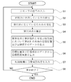
- the control unit of the puncture robot executes the subroutine shown in FIG. 5 while driving the advance / retreat mechanism 32e as usual and puncturing the patient with the puncture needle 10.
- the deflection generated in the puncture needle 10 is eliminated.
- the control unit of the puncture robot receives signals output from the first force sensor 23a and the second force sensor 23b (step S1), and detects the force acting on the puncture needle 10 from the obtained signals. (Step S2).
- the puncture state of the puncture needle 10 may be abnormal and the emergency stop may be performed.
- the force acting on the puncture needle 10 may be detected by each of the first force sensor 23a and the second force sensor 23b, an average value may be calculated, and this average value may be used. In the following description, average value data is used.
- the control unit of the puncture robot estimates the deflection generated in the puncture needle 10 (step S3), and the surface of the body surface when the puncture needle 10 punctures the patient is estimated.
- the position of the puncture point is calculated (step S4).
- the control unit of the puncture robot After calculating the position of the puncture point, the control unit of the puncture robot sets a virtual line connecting the puncture point and the puncture target, and the position of the proximal end of the puncture needle 10 and the puncture needle on the extension line of the virtual line Position data and inclination data are generated using the 10 inclinations as a target position and a target inclination (step S5).
- the control unit of the puncture robot uses the inverse kinematics based on the target position and target tilt data, and the first parallel moving mechanism 32a, the second parallel moving mechanism 32b, A target joint angle to be input to the first rotation mechanism 32c, the second rotation mechanism 32d, the advance / retreat mechanism 32e, and the elevating mechanism is calculated (step S6) and input to each of them (step S7).
- the control unit of the puncture robot eliminates the bending that occurs in the puncture needle 10 by superimposing the target joint angle data while performing the puncture of the puncture needle 10.
- the control unit of the puncture robot returns from step S8 to step S1 unless the puncture is completed, and repeatedly executes optimization of the position of the proximal end of the puncture needle 10 and the inclination of the puncture needle 10.
- the following table shows the results of a puncture test using the puncture robot of the present invention and a commercially available phantom.
- a tungsten ball with a diameter of 1 mm was embedded at a depth of 77 mm from the epidermis and used as a puncture target.
- the puncture needle was punctured toward the puncture target, the distance between the tip of the puncture needle and the puncture target was measured and evaluated.
- the puncture needle When a phantom is punctured with a puncture needle, unlike a living body, the puncture needle does not bend. Therefore, by deflecting the phantom with the tip of the puncture needle inserted into the phantom, the puncture needle is deflected. Then, the puncture of the puncture needle is resumed.
- a biopsy introduction needle having a needle length of 114 mm and 17G and 19G biopsy introduction needles were used.
- “Simple insertion” is a case where puncture is performed without eliminating the bending that occurred in the puncture needle
- “Automatic” is a case where puncture is performed while eliminating the deflection of the puncture needle by puncturing with the puncture robot of the present invention. It can be seen that the puncture accuracy is improved. In particular, under the conditions of this test, the target accuracy is 2.5 mm, indicating that the target accuracy has been achieved.
Landscapes
- Health & Medical Sciences (AREA)
- Engineering & Computer Science (AREA)
- Surgery (AREA)
- Life Sciences & Earth Sciences (AREA)
- Medical Informatics (AREA)
- General Health & Medical Sciences (AREA)
- Biomedical Technology (AREA)
- Heart & Thoracic Surgery (AREA)
- Nuclear Medicine, Radiotherapy & Molecular Imaging (AREA)
- Molecular Biology (AREA)
- Animal Behavior & Ethology (AREA)
- Robotics (AREA)
- Public Health (AREA)
- Veterinary Medicine (AREA)
- Human Computer Interaction (AREA)
- Mechanical Engineering (AREA)
- Pathology (AREA)
- Surgical Instruments (AREA)
- Manipulator (AREA)
Abstract
穿刺針を遠隔操作で患者に穿刺する穿刺ロボットにおいて、穿刺精度の高い穿刺ロボット及び穿刺制御プログラムを提供する。 患者の体内の穿刺標的を穿刺する穿刺針(10)と、この穿刺針(10)の基端を着脱自在に支持する針支持部(21)を先端に備えたアーム(20)と、このアームを(20)介して穿刺針の位置及び傾きを調整する調整機構を備えた本体部(30)とを有する穿刺ロボットにおいて、アーム(20)には、穿刺針に作用する力を検出する力センサを設け、調整機構は、穿刺針(10)で患者を穿刺した際に、穿刺針(10)の位置及び傾きを調整することで力センサで検出された力を解消する。
Description
本発明は、穿刺ロボット及び穿刺制御用プログラムに関し、より詳しくは、穿刺針を患者に遠隔操作で穿刺する穿刺ロボットであって、穿刺針に生じるたわみを抑制することで穿刺の標的を確実に穿刺する穿刺ロボット及び穿刺制御用プログラムに関する。
本発明者らは、CT(Computed Tomography)によるX線透視下において患者の腫瘍等の病変部に穿刺針を穿刺する際に使用する穿刺ロボットを開発している。
この穿刺ロボットでは、X線のアーチファクトの発生を抑制するために、穿刺針を比較的長尺のアームの先端に装着し、アームに対して適宜の平行移動操作あるいは回転操作を行うことで穿刺針を穿刺経路上に位置させ、この穿刺経路に沿って穿刺針を直動させることで穿刺することとしていた(例えば、特許文献1参照。)。ここで、穿刺経路とは、穿刺の標的である腫瘍等の患部の中心を通る仮想線であって、骨や主要な器官等を避けながら穿刺針を刺し込んだ際の差し込みの長さができるだけ短くなる仮想線である。
また、穿刺経路を決定する際には、穿刺針が刺し貫く生体組織の柔らかさの影響を想定することも重要である。他の同様の穿刺ロボットでは、生体組織の柔らかさ等の物理情報等に基づいたモデルを設定してから穿刺経路を決定し、穿刺制御をすることが提案されている(例えば、特許文献2参照。)。さらに、この穿刺ロボットでは、穿刺中に超音波診断装置や磁気共鳴画像診断装置等の画像取得装置で穿刺針に生じるたわみの影響を検出し、穿刺経路を補正することも提案されている。しかも、この穿刺ロボットでは、穿刺針に生じる力を力センサで検出し、標的となっている病変部の穿刺針による刺し過ぎを検出することも提案されている。
本発明者らが開発している穿刺ロボットでは、穿刺針による穿刺をできるだけ速やかに行うことで、生体組織の柔らかさ等の影響を受けにくくすることができるものと考えていたが、豚等を用いた動物実験の結果では十分な精度での標的の穿刺が行えていないという問題があった。
本発明者らは、十分な精度が得られない原因を研究したところ、穿刺針で患者を穿刺した際に、体内に刺し込まれる直前に穿刺針にたわみが生じ、この穿刺針のたわみとともに患者の体表面もたわみ、その後、穿刺針が体内に進入することとなっているために、穿刺針が体内に進入する穿刺地点があらかじめ想定していた穿刺地点からずれ、しかも、穿刺針がたわんだ状態のまま刺し込まれることで穿刺経路からずれていることがわかった。
そこで、この穿刺針のたわみを解消することで、標的に対する穿刺精度を向上させることができるものと考えた。
しかも、穿刺針にたわみを生じさせている力は、穿刺針で患者を穿刺した際に穿刺針に作用する反力であって、この反力の方向と大きさを穿刺針が装着されているアームに設けている力センサで検出可能であることを見いだした。この力センサはもともと安全装置として設けているものであって、穿刺針を患者に穿刺した際に何らかの異常が生じたことを力センサで検出して、緊急停止等の危機回避動作を開始させるために用いているものである。
すなわち、本発明の穿刺ロボットは、患者の体内の穿刺標的を穿刺する穿刺針と、この穿刺針の基端を着脱自在に支持する針支持部を先端に備えたアームと、このアームを介して穿刺針の位置及び傾きを調整する調整機構を備えた本体部とを有する穿刺ロボットにおいて、アームには、穿刺針に作用する力を検出する力センサを設け、調整機構は、穿刺針で患者を穿刺した際に、穿刺針の位置及び傾きを調整することで力センサで検出された力を解消することとした。
さらに、本発明の穿刺ロボットでは、調整機構で穿刺針の位置及び傾きを調整して、穿刺針が患者を穿刺した際の体表面の穿刺地点と穿刺標的とを結ぶ仮想線の延長線上に穿刺針の基端を位置させることで前記力センサで検出された力を解消することにも特徴を有するものである。
また、本発明の穿刺制御用プログラムでは、アームの先端に基端が着脱自在に支持された穿刺針の位置及び傾きを制御するとともに、穿刺針をこの穿刺針の延伸方向に直動させることで患者の体内の穿刺標的を穿刺する穿刺ロボットの穿刺制御用プログラムであって、アームに設けた力センサで穿刺針に作用した力を検出するステップと、検出された力によって穿刺針に生じるたわみを推定して、穿刺針が患者を穿刺した際の体表面の穿刺地点の位置を算出するステップと、この穿刺地点と穿刺標的とを結ぶ仮想線の延長線上となる穿刺針の基端の位置及び穿刺針の傾きを特定するステップと、穿刺針の基端をこの特定された位置とするとともに穿刺針を特定された傾きとするステップとを有するものである。
本発明によれば、穿刺針による患者の穿刺によって穿刺針に生じたたわみを解消しながら穿刺を行うことで、穿刺標的の穿刺精度を向上させることができる。
まず、本発明において想定している穿刺針の穿刺状態のモデルについて説明する。本発明では、穿刺針がたわんだ際に、穿刺針には患者への穿刺地点に荷重が集中して作用しているものと仮定している。すなわち、集中荷重の作用した片持ち梁のモデルを流用できると考えて、図1に示すようにモデルを設定した。
図1において、
Fy[N]:たわみ力
δ[mm]:たわみによる変位
lE[mm]:穿刺針の長さ
lin[mm]:穿刺針の刺し入れられた長さ
lpunc[mm]:予定の穿刺深さ
lrem[mm]:残りの穿刺量
(yt,zt):穿刺標的の座標
(y0,z0):穿刺針の基端の座標
ΦA0[rad]:穿刺針の傾き
である。
Fy[N]:たわみ力
δ[mm]:たわみによる変位
lE[mm]:穿刺針の長さ
lin[mm]:穿刺針の刺し入れられた長さ
lpunc[mm]:予定の穿刺深さ
lrem[mm]:残りの穿刺量
(yt,zt):穿刺標的の座標
(y0,z0):穿刺針の基端の座標
ΦA0[rad]:穿刺針の傾き
である。
材料力学の公式より、穿刺針の断面二次モーメントI[mm4]と、穿刺針のたわみによる変位δ[mm]は、下式で表せる。

ここで、Eは穿刺針のヤング率[MPa]、dは穿刺針の断面の直径[mm]である。
また、残りの穿刺量lrem[mm]は、予定の穿刺深さlpunc[mm]と穿刺針の刺し入れられた長さlin[mm]とを用いて、下式で表せる。

穿刺針の穿刺地点と、穿刺標的とを結ぶ仮想線の延長線上に穿刺針の基端を位置させるとして、その座標を(y*,z*)とすると、座標の値は下式で表せる。

ここで、Φ*
Aは目標姿勢の傾きであり、ΔΦAを目標回転角度とすると、目標回転角度ΔΦAと目標姿勢の傾きΦ*
Aは、下式で表せる。

さらに、穿刺標的(yt,zt)の座標の値は、下式で表せる。

これらを用いて、穿刺針の基端の座標(y*,z*)と傾きΦ*
Aを求めることができる。得られた(y*,z*,Φ*
A)を用いて穿刺針の基端の位置及び穿刺針の傾きをこの位置及び傾きとすることで穿刺針に生じる撓みを解消でき、穿刺標的の穿刺精度を向上させることができる。
以下において、本発明の穿刺ロボットを説明する。図2に示すように、本発明の穿刺ロボットは、穿刺針10の基端を着脱自在に支持する針支持部21を先端に備えたアーム20と、このアーム20を介して穿刺針10の位置及び傾きを調整する調整機構を備えた本体部30とを有している。
本体部30では、矩形体状の基台31を有し、この基台31の上面には、第1の水平方向への平行移動を制御する第1平行移動機構32aを設けている。この第1平行移動機構32aの上面には、第1の水平方向と直行する第2の水平方向への平行移動を制御する第2平行移動機構32bを設けている。第2平行移動機構32bの先端部には、第1の水平方向と平行に延伸させた回動ロッド33を有する第1回動機構32cを設け、回動ロッド33の中心軸周りに回動ロッド33を回動制御している。回動ロッド33の先端には、回動ロッド33の延伸方向と直交する回転軸(図示せず)を介して進退機構32eが装着される第2回動機構32dを設け、この第2回動機構32dと第1回動機構32cとで穿刺針10の傾きを自在に制御可能としている。進退機構32eは、この進退機構32eに基端側が装着されたアーム20を穿刺針10の延伸方向に進退移動させことで、穿刺針10をその延伸方向に沿って進退制御している。さらに、図示していないが、基台31の内部には、第1平行移動機構32aを鉛直方向に昇降させる昇降機構を設けており、これらの6自由度の制御を行うことで、穿刺針10の位置と傾きとを自由自在に制御可能としている。
図3に詳細に示すように、アーム20は、第1アーム20aと第2アーム20bとを有し、この第1アーム20aと第2アーム20bとで平行リンクを構成することで、進退機構32eの進退方向を穿刺針10の延伸方向と平行としている。したがって、進退機構32eを進退制御することで、穿刺針10を延伸方向に沿って直動させることができる。
第1アーム20aと第2アーム20bの先端側は矩形フレーム22に回動自在に装着している。矩形フレーム22は、底面壁22aと、この底面壁22aと対向した天井壁22bと、底面壁22aと天井壁22bとに架設した第1側壁22cと第2側壁(図示せず)とで構成しており、第1側壁22cと第2側壁に第1アーム20aと第2アーム20bの先端側を回転自在に装着している。
底面壁22aの上面には第1力センサ23aと第2力センサ23bを重ねて載設している。第1力センサ23aと第2力センサ23bの2つの力センサを設けているのは、力センサの一方が故障した場合のフェイルセーフ用としてである。
第2力センサ23bの上面には、第1アーム20a及び第2アーム20bの延伸方向に向けて延出させた支持片24を設け、この支持片24の下面にエアシリンダ25を装着している。このエアシリンダ25は、穿刺針10を延伸方向と平行に進退するロッド(図示せず)を有しており、進退機構32eの駆動速度よりも速い速度で穿刺針10を直動させることで、患者の皮膚を穿刺しやすくしている。
エアシリンダ25のロッドには、針支持部21を固定装着するための連結体26を装着しており、針支持部21は、図3及び図4に示すように2つの固定ピン27を介して連結体26に固定装着することとしている。
針支持部21の基体21aの先端側には、図4に示すように、第1針把持アーム21bと第2針把持アーム21cを回動自在に設けており、この第1針把持アーム21bと第2針把持アーム21cとで、穿刺針10の基端を把持することとしている。特に、第1針把持アーム21bと第2針把持アーム21cとは、穿刺針10を把持した後にスナップ錠21dで一体的に連結して、穿刺針10を強固に支持可能としている。
本発明の穿刺ロボットは、図示しないコントローラを用いて遠隔操作を可能としており、CTの寝台に寝た患者に対して、X線透過下で穿刺標的を確認しながらコントローラで穿刺ロボットの調整機構を操作して、穿刺針10を穿刺経路上に位置させることとしている。
穿刺針10を穿刺経路上に位置させた後、穿刺針10の穿刺を開始させることで進退機構32eを駆動させて、患者に対して穿刺針10の穿刺を行う。
ここで、本発明の穿刺ロボットでは、従前通りに進退機構32eを駆動させて、患者に対して穿刺針10による穿刺を行いながら、穿刺ロボットの制御部は、図5に示すサブルーチンを実行して、穿刺針10に生じるたわみを解消している。
すなわち、まず、穿刺ロボットの制御部は、第1力センサ23aと第2力センサ23bから出力された信号を受け付け(ステップS1)、得られた信号から穿刺針10に作用している力を検出する(ステップS2)。ここで、検出された力の大きさが、あらかじめ設定された閾値よりも大きい場合には、穿刺針10の穿刺状態が異常であるとして、緊急停止させてもよい。また、第1力センサ23aと第2力センサ23bのそれぞれで穿刺針10に作用している力を検出して、平均値を算出し、この平均値を用いてもよい。以下の説明では、平均値のデータを用いるものとする。
穿刺針10に作用している力を検出した後、穿刺ロボットの制御部は、穿刺針10に生じているたわみを推定し(ステップS3)、穿刺針10が患者を穿刺した際の体表面の穿刺地点の位置を算出する(ステップS4)。
穿刺地点の位置を算出した後、穿刺ロボットの制御部は、この穿刺地点と穿刺標的とを結ぶ仮想線を設定し、この仮想線の延長線上となる穿刺針10の基端の位置及び穿刺針10の傾きを、目標位置及び目標傾きとして位置データ及び傾きデータを生成する(ステップS5)。
目標位置及び目標傾きのデータの生成後、穿刺ロボットの制御部は、目標位置及び目標傾きのデータに基づいて逆運動学を用いて、第1平行移動機構32a、第2平行移動機構32b、第1回動機構32c、第2回動機構32d、進退機構32e、昇降機構に入力する目標関節角度を算出し(ステップS6)、それぞれに入力する(ステップS7)。
穿刺ロボットの制御部は、穿刺針10の刺し込みを行いながら、目標関節角度のデータを重ね合わせて制御し、穿刺針10に生じる撓みを解消している。
穿刺ロボットの制御部は、穿刺が終了していない限りは、ステップS8からステップS1に戻り、穿刺針10の基端の位置及び穿刺針10の傾きの最適化を繰り返し実行する。
本発明の穿刺ロボットを用い、市販のファントムを用いて穿刺試験を行った結果を下表に示す。ファントムには表皮から77mmの深さに直径1mmのタングステン球を埋設して穿刺標的とした。穿刺標的に向けて穿刺針を穿刺した際に、穿刺針の針先と穿刺標的の距離を計測して評価した。

なお、穿刺針でファントムを穿刺した際には、生体と異なり穿刺針に撓みが生じないため、穿刺針の先端がファントムに差し込まれた状態でファントムをずらせることで穿刺針にたわみを生じさせ、その後に穿刺針の穿刺を再開させている。
本試験では、針長さが114mmの生検導入針であって、17Gと19Gの生検導入針を用いた。「Simple insertion」は、穿刺針に生じた撓みを解消させずに穿刺した場合であり、「Automatic」は、本発明の穿刺ロボットで穿刺することで穿刺針のたわみを解消させながら穿刺した場合であり、穿刺精度が向上していることがわかる。特に、本試験の条件では、目標精度は2.5mmであり、目標精度を達成していることがわかる。
以上の本発明では、穿刺針を穿刺する際に、穿刺針に生じる撓みを解消させる制御を行いながら穿刺を行うことで鮮度のよい穿刺を行うことができる。特に、既知の穿刺ロボットのように、生体組織の柔らかさを考慮する必要がなく穿刺を行うことができるので、事前準備の手間を大きく低減させることもできる。
10 穿刺針
20 アーム
21 針支持部
20a 第1アーム
20b 第2アーム
22 矩形フレーム
23a 第1力センサ
23b 第2力センサ
24 支持片
25 エアシリンダ
26 連結体
27 固定ピン
30 本体部
31 基台
32a 第1平行移動機構
32b 第2平行移動機構
32c 第1回動機構
32d 第2回動機構
32e 進退機構
20 アーム
21 針支持部
20a 第1アーム
20b 第2アーム
22 矩形フレーム
23a 第1力センサ
23b 第2力センサ
24 支持片
25 エアシリンダ
26 連結体
27 固定ピン
30 本体部
31 基台
32a 第1平行移動機構
32b 第2平行移動機構
32c 第1回動機構
32d 第2回動機構
32e 進退機構
Claims (3)
- 患者の体内の穿刺標的を穿刺する穿刺針と、
この穿刺針の基端を着脱自在に支持する針支持部を先端に備えたアームと、
このアームを介して前記穿刺針の位置及び傾きを調整する調整機構を備えた本体部と
を有する穿刺ロボットにおいて、
前記アームには、前記穿刺針に作用する力を検出する力センサを設け、
前記調整機構は、前記穿刺針で前記患者を穿刺した際に、前記穿刺針の位置及び傾きを調整することで前記力センサで検出された力を解消する穿刺ロボット。 - 前記調整機構は、前記穿刺針の位置及び傾きを調整して、前記穿刺針が前記患者を穿刺した際の体表面の穿刺地点と前記穿刺標的とを結ぶ仮想線の延長線上に穿刺針の基端を位置させることで前記力センサで検出された力を解消する請求項1に記載の穿刺ロボット。
- アームの先端に基端が着脱自在に支持された穿刺針の位置及び傾きを制御するとともに、前記穿刺針をこの穿刺針の延伸方向に直動させることで患者の体内の穿刺標的を穿刺する穿刺ロボットの穿刺制御用プログラムにおいて、
前記アームに設けた力センサで前記穿刺針に作用した力を検出するステップと、
前記力によって前記穿刺針に生じるたわみを推定して、前記穿刺針が前記患者を穿刺した際の体表面の穿刺地点の位置を算出するステップと、
前記穿刺地点と前記穿刺標的とを結ぶ仮想線の延長線上となる前記穿刺針の基端の位置及び穿刺針の傾きを特定するステップと、
前記穿刺針の基端を前記の特定された位置、及び穿刺針の傾きを前記の特定された傾きとするステップと
を有する穿刺制御用プログラム。
Priority Applications (1)
| Application Number | Priority Date | Filing Date | Title |
|---|---|---|---|
| JP2019517494A JPWO2018207498A1 (ja) | 2017-05-09 | 2018-03-30 | 穿刺ロボット及び穿刺制御用プログラム |
Applications Claiming Priority (2)
| Application Number | Priority Date | Filing Date | Title |
|---|---|---|---|
| JP2017093371 | 2017-05-09 | ||
| JP2017-093371 | 2017-05-09 |
Publications (1)
| Publication Number | Publication Date |
|---|---|
| WO2018207498A1 true WO2018207498A1 (ja) | 2018-11-15 |
Family
ID=64105223
Family Applications (1)
| Application Number | Title | Priority Date | Filing Date |
|---|---|---|---|
| PCT/JP2018/013938 Ceased WO2018207498A1 (ja) | 2017-05-09 | 2018-03-30 | 穿刺ロボット及び穿刺制御用プログラム |
Country Status (2)
| Country | Link |
|---|---|
| JP (1) | JPWO2018207498A1 (ja) |
| WO (1) | WO2018207498A1 (ja) |
Cited By (10)
| Publication number | Priority date | Publication date | Assignee | Title |
|---|---|---|---|---|
| CN109499009A (zh) * | 2018-12-12 | 2019-03-22 | 深圳先进技术研究院 | 一种用于植入放射性粒子的机器人 |
| CN110101439A (zh) * | 2019-06-03 | 2019-08-09 | 无锡华飞杰希科技有限公司 | 一种超声介入穿刺导航系统及穿刺架 |
| CN110123426A (zh) * | 2019-06-03 | 2019-08-16 | 无锡华飞杰希科技有限公司 | 一种超声介入穿刺导航系统及穿刺架 |
| JP2020162969A (ja) * | 2019-03-29 | 2020-10-08 | 国立大学法人 岡山大学 | 穿刺ロボット及び穿刺制御用プログラム |
| CN112274225A (zh) * | 2020-05-11 | 2021-01-29 | 肩并肩智能技术(北京)有限公司 | 用于医疗手术机器人的末端穿刺机构及穿刺手术机器人 |
| JP2022518870A (ja) * | 2019-01-25 | 2022-03-16 | 李漢忠 | 経尿道的レゼクトスコープ手術ロボットシステム |
| CN114917000A (zh) * | 2022-05-24 | 2022-08-19 | 武汉联影智融医疗科技有限公司 | 一种穿刺器械辅助组件 |
| WO2022247837A1 (zh) * | 2021-05-24 | 2022-12-01 | 武汉联影智融医疗科技有限公司 | 一种穿刺装置及穿刺系统 |
| CN115778502A (zh) * | 2022-11-23 | 2023-03-14 | 无锡学院 | 一种提高前列腺粒子植入针穿刺精度的矫正器 |
| CN116570347A (zh) * | 2022-11-23 | 2023-08-11 | 无锡学院 | 基于矫正力微创介入治疗系统及组织杨氏模量识别方法 |
Citations (4)
| Publication number | Priority date | Publication date | Assignee | Title |
|---|---|---|---|---|
| JP2006271546A (ja) * | 2005-03-28 | 2006-10-12 | Univ Waseda | 穿刺制御装置、穿刺ロボット及び穿刺制御用プログラム |
| JP2014004212A (ja) * | 2012-06-26 | 2014-01-16 | Canon Inc | 穿刺制御装置及び方法 |
| JP2016027844A (ja) * | 2014-07-10 | 2016-02-25 | キヤノン株式会社 | 穿刺プランニング装置及び穿刺システム |
| WO2017065016A1 (ja) * | 2015-10-13 | 2017-04-20 | 国立大学法人 岡山大学 | 穿刺ロボット |
-
2018
- 2018-03-30 JP JP2019517494A patent/JPWO2018207498A1/ja active Pending
- 2018-03-30 WO PCT/JP2018/013938 patent/WO2018207498A1/ja not_active Ceased
Patent Citations (4)
| Publication number | Priority date | Publication date | Assignee | Title |
|---|---|---|---|---|
| JP2006271546A (ja) * | 2005-03-28 | 2006-10-12 | Univ Waseda | 穿刺制御装置、穿刺ロボット及び穿刺制御用プログラム |
| JP2014004212A (ja) * | 2012-06-26 | 2014-01-16 | Canon Inc | 穿刺制御装置及び方法 |
| JP2016027844A (ja) * | 2014-07-10 | 2016-02-25 | キヤノン株式会社 | 穿刺プランニング装置及び穿刺システム |
| WO2017065016A1 (ja) * | 2015-10-13 | 2017-04-20 | 国立大学法人 岡山大学 | 穿刺ロボット |
Cited By (14)
| Publication number | Priority date | Publication date | Assignee | Title |
|---|---|---|---|---|
| CN109499009A (zh) * | 2018-12-12 | 2019-03-22 | 深圳先进技术研究院 | 一种用于植入放射性粒子的机器人 |
| JP7239739B2 (ja) | 2019-01-25 | 2023-03-14 | 李漢忠 | 経尿道的レゼクトスコープ手術ロボットシステム |
| JP2022518870A (ja) * | 2019-01-25 | 2022-03-16 | 李漢忠 | 経尿道的レゼクトスコープ手術ロボットシステム |
| JP2020162969A (ja) * | 2019-03-29 | 2020-10-08 | 国立大学法人 岡山大学 | 穿刺ロボット及び穿刺制御用プログラム |
| JP7244909B2 (ja) | 2019-03-29 | 2023-03-23 | 国立大学法人 岡山大学 | 穿刺ロボット及び穿刺制御用プログラム |
| CN110123426A (zh) * | 2019-06-03 | 2019-08-16 | 无锡华飞杰希科技有限公司 | 一种超声介入穿刺导航系统及穿刺架 |
| CN110101439A (zh) * | 2019-06-03 | 2019-08-09 | 无锡华飞杰希科技有限公司 | 一种超声介入穿刺导航系统及穿刺架 |
| CN110101439B (zh) * | 2019-06-03 | 2024-04-05 | 北京奥达智声医疗科技有限公司 | 一种超声介入穿刺导航系统及穿刺架 |
| CN110123426B (zh) * | 2019-06-03 | 2024-04-12 | 北京奥达智声医疗科技有限公司 | 一种超声介入穿刺导航系统及穿刺架 |
| CN112274225A (zh) * | 2020-05-11 | 2021-01-29 | 肩并肩智能技术(北京)有限公司 | 用于医疗手术机器人的末端穿刺机构及穿刺手术机器人 |
| WO2022247837A1 (zh) * | 2021-05-24 | 2022-12-01 | 武汉联影智融医疗科技有限公司 | 一种穿刺装置及穿刺系统 |
| CN114917000A (zh) * | 2022-05-24 | 2022-08-19 | 武汉联影智融医疗科技有限公司 | 一种穿刺器械辅助组件 |
| CN115778502A (zh) * | 2022-11-23 | 2023-03-14 | 无锡学院 | 一种提高前列腺粒子植入针穿刺精度的矫正器 |
| CN116570347A (zh) * | 2022-11-23 | 2023-08-11 | 无锡学院 | 基于矫正力微创介入治疗系统及组织杨氏模量识别方法 |
Also Published As
| Publication number | Publication date |
|---|---|
| JPWO2018207498A1 (ja) | 2020-05-14 |
Similar Documents
| Publication | Publication Date | Title |
|---|---|---|
| WO2018207498A1 (ja) | 穿刺ロボット及び穿刺制御用プログラム | |
| CN105813585B (zh) | 通过杆操纵实现的针转向 | |
| US20220370161A1 (en) | Systems and methods for aligning an elongate member with an access site | |
| CN110236681B (zh) | 一种穿刺机器人及其机械臂用进针系统 | |
| JP5103658B2 (ja) | 柔軟な針の制御された操作 | |
| CN114041880A (zh) | 一种医疗手术机器人的末端穿刺执行装置 | |
| CN102018575B (zh) | 机器人辅助柔性针穿刺软组织实时操控系统及方法 | |
| US12245748B2 (en) | Endoscopic capsule system with haptic feedback | |
| JP2005237964A (ja) | ロボットガイドカテーテル | |
| JPH07184929A (ja) | 手術装置 | |
| JP7244909B2 (ja) | 穿刺ロボット及び穿刺制御用プログラム | |
| US20260041414A1 (en) | Method and system for controlling flexible devices in presence of abnormal sensor signals | |
| JP4953303B2 (ja) | 病変部位の位置特定システム | |
| CN117796910B (zh) | 穿刺机器人及电子设备 | |
| Sugiyama et al. | Reaction force analysis of puncture robot for CT-guided Interventional Radiology in animal experiment | |
| CN111803214B (zh) | 一种手术机器人装置 | |
| CN211534705U (zh) | 介入穿刺系统及具有其的诊疗设备 | |
| CN117224233B (zh) | 一种一体化透视ct及介入手术机器人系统及其使用方法 | |
| CN120884348A (zh) | 一种超声引导臂丛神经阻滞麻醉穿刺设备及方法 | |
| JP4785114B2 (ja) | マーカ保持具及びこれを用いた生体組織の動作検出システム |
Legal Events
| Date | Code | Title | Description |
|---|---|---|---|
| 121 | Ep: the epo has been informed by wipo that ep was designated in this application |
Ref document number: 18798919 Country of ref document: EP Kind code of ref document: A1 |
|
| ENP | Entry into the national phase |
Ref document number: 2019517494 Country of ref document: JP Kind code of ref document: A |
|
| NENP | Non-entry into the national phase |
Ref country code: DE |
|
| 122 | Ep: pct application non-entry in european phase |
Ref document number: 18798919 Country of ref document: EP Kind code of ref document: A1 |