WO2018203529A1 - 眼科装置、およびそれに用いる光学素子 - Google Patents
眼科装置、およびそれに用いる光学素子 Download PDFInfo
- Publication number
- WO2018203529A1 WO2018203529A1 PCT/JP2018/017211 JP2018017211W WO2018203529A1 WO 2018203529 A1 WO2018203529 A1 WO 2018203529A1 JP 2018017211 W JP2018017211 W JP 2018017211W WO 2018203529 A1 WO2018203529 A1 WO 2018203529A1
- Authority
- WO
- WIPO (PCT)
- Prior art keywords
- light
- optical element
- eye
- optical system
- optical
- Prior art date
- Legal status (The legal status is an assumption and is not a legal conclusion. Google has not performed a legal analysis and makes no representation as to the accuracy of the status listed.)
- Ceased
Links
Images





Classifications
-
- A—HUMAN NECESSITIES
- A61—MEDICAL OR VETERINARY SCIENCE; HYGIENE
- A61B—DIAGNOSIS; SURGERY; IDENTIFICATION
- A61B3/00—Apparatus for testing the eyes; Instruments for examining the eyes
- A61B3/10—Objective types, i.e. instruments for examining the eyes independent of the patients' perceptions or reactions
- A61B3/117—Objective types, i.e. instruments for examining the eyes independent of the patients' perceptions or reactions for examining the anterior chamber or the anterior chamber angle, e.g. gonioscopes
Definitions
- the present disclosure relates to an ophthalmologic apparatus that captures a corner image of an eye to be examined, and an optical element used therefor.
- Patent Document 1 discloses an apparatus that irradiates illumination light at a corner angle of an eye to be examined and obtains a reflected image of the corner angle based on reflected light from the corner angle.
- a part of the illumination light for illuminating the corner angle is scattered or reflected inside the optical system and enters the fundus of the subject's eye, and the subject feels glare. There was a problem.
- the first embodiment according to the present disclosure is characterized by having the following configuration.
- An ophthalmologic apparatus for photographing a corner angle of an eye to be examined which includes a light projecting optical system that projects illumination light onto the corner angle of the eye to be examined, and a light receiving element that receives reflected light from the corner angle.
- An optical system, and at least a part of the optical element of the light projecting optical system is provided with a light shielding portion.
- An optical element used in an ophthalmologic apparatus for photographing a corner angle of an eye to be examined which includes a reflective surface provided on the front surface side of the optical element, and a translucent surface provided on the rear surface side of the optical element; And a light shielding portion provided on the light transmitting surface.
- the second embodiment according to the present disclosure is characterized by having the following configuration.
- An ophthalmologic apparatus for photographing a corner angle of a subject's eye a projection optical system that projects illumination light onto the corner of the subject's eye, and an optical element that is inserted on the optical axis of the projection optical system
- a mounting portion that can be mounted, and the mounting portion includes a regulating unit that regulates a posture of the optical element.
- 1st Embodiment is an ophthalmologic apparatus (for example, ophthalmologic apparatus 1) which image
- the ophthalmologic apparatus according to the first embodiment includes, for example, a light projecting optical system (for example, a light projecting optical system 30) and a light receiving optical system (light receiving optical system 60).
- the light projecting optical system projects illumination light to the corner of the eye to be examined.
- the light receiving optical system includes a light receiving element that receives reflected light from a corner.
- the light projecting optical system includes a light shielding part (for example, a light shielding part 50a).
- the light shielding unit is provided, for example, in at least a part of the optical elements of the light projecting optical system.
- the light shielding unit shields stray light generated by reflecting or diffusing illumination light for illuminating the eye to be examined inside the light projecting optical system.
- the light shielding unit suppresses the generation of stray light that occurs when the illumination light is diffused or reflected inside the optical system.
- the ophthalmologic apparatus can suppress stray light from entering the fundus of the subject's eye and reduce the burden on the subject.
- a light-shielding part is provided in the center area
- the light shielding portion may be an annular shape having an opening (opening 50b) in the center.
- a fixation light beam from the fixation optical system may be incident on the eye to be examined through the opening.
- the light projecting optical system includes a first optical element (for example, the objective reflection unit 50) and a second optical element (for example, the lens 49) that are adjacent in the optical axis direction, and the light shielding unit includes the first optical element and the second optical element. Each may be provided on the opposite side of the element.
- the light shielding part may be formed by black printing or may be formed by printing of another color.
- the light shielding portion may be formed by painting or coating.
- the light shielding portion may be a black chrome (chromium oxide) coating.
- the optical element may have a reflective surface on the front side with respect to the eye to be examined and a translucent surface on the rear side.
- the optical element may be a mirror prism.
- the second embodiment is also an ophthalmologic apparatus that photographs the corners of the eye to be examined, as in the first embodiment.
- the ophthalmologic apparatus of 2nd Embodiment is provided with a mounting part (for example, mounting part 90).
- the mounting unit can mount an optical element (for example, the objective reflection unit 50) that is inserted on the optics of the light projecting optical system.
- the mounting unit includes a regulating unit that regulates the posture of the optical element.
- the ophthalmic apparatus according to the second embodiment can prevent the optical element from being mounted in a posture different from normal by restricting the posture of the optical element mounted on the mounting portion.
- the optical element may be an objective optical element.
- the objective optical element is, for example, an optical element closest to the eye to be examined.
- the restricting unit may restrict the rotation angle of the optical element around the optical axis.
- the restricting unit restricts the rotation angle of the optical element so that the reflecting surface faces a predetermined direction.
- the restricting portion may include a fitting portion (for example, the fitting portion 95).
- a fitting part regulates the attitude
- the fitting portion may regulate the posture of the optical element by fitting with a convex portion provided on the holder.
- the mounting portion may be cylindrical.
- the fitting part may be a notch provided in the cylindrical mounting part.
- a part of the holder may be fitted into the notch to regulate the posture of the holder.
- the fitting portion is not limited to the notch, and may be a recess.
- the mounting part may include two or more fitting parts. Moreover, you may prevent that a holder is mounted
- the fitting portion may be disposed at a position where the shape of the mounting portion is asymmetric with respect to any meridian.
- the meridian is based on the center of the optical axis of the optical element held by the holder, for example.
- the holder may include a gripping portion.
- the grip portion is, for example, a handle when the examiner has a holder.
- the fitting portion may be fitted with a grip portion provided on the holder.
- the restricting portion may include a fitting portion that fits the entire holder.
- the fitting portion and the holder are polygonal (for example, hexagonal), and the fitting portion and the entire holder are fitted to prevent rotation of the optical element and restrict the posture of the optical element. Good.
- the mounting unit may include a magnetic body (for example, a magnet) for holding the holder. This can prevent the holder from being unintentionally detached from the mounting portion.
- a magnetic body for example, a magnet
- the ophthalmologic apparatus 1 is a corner photographing apparatus.
- the ophthalmologic apparatus 1 captures a reflection image (see FIG. 1) of the corner of the eye to be examined.
- ⁇ Device configuration> With reference to FIG. 2, a schematic apparatus configuration in the ophthalmic apparatus 1 will be described.
- the X direction shown in FIG. 2 is described as the left-right direction
- the Y direction is the up-down direction
- the Z direction is the front-back direction.
- the ophthalmologic apparatus 1 irradiates illumination light in an oblique direction with respect to the visual axis of the eye E. Then, the ophthalmologic apparatus 1 receives reflected light from the corner area along the photographing optical axis, thereby capturing an image in the corner area of the eye to be examined.
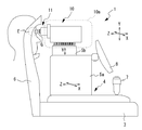
- the ophthalmologic apparatus 1 includes a base 3, alignment mechanisms 4, 5a, 5b, a face support unit 6, a joystick 7, a monitor 8, an optical unit 10, and the like.
- the optical unit 10 has a main optical system used for taking a corner image. Details of the optical system will be described later with reference to FIG.
- the optical unit 10 is accommodated in the cover 10a. However, the tip portion 11 is exposed outside the cover 10a.
- the base 3 supports the alignment mechanisms 4, 5 a, 5 b and the face support unit 6.
- the alignment mechanisms 4, 5a, 5b in the present embodiment are roughly divided into a movable table 4 and XYZ driving units 5a, 5b.
- the movable table 4 is operated by a mechanical mechanism
- the XYZ driving units 5a and 5b are operated by an electric actuator.
- the moving table 4 is disposed on the base 3 and has a mechanical moving mechanism between the moving table 4 and the base 3. This moving mechanism moves the moving table 4 in the XZ direction, and as a result, adjusts the positional relationship between the eye E to be examined and the optical unit 10 in the XZ direction.
- the examiner operates the joystick 7 to move the movable table 4 relative to the base 3.
- XYZ driving units 5a and 5b in the present embodiment are further stacked on the movable table 4.
- the XYZ driving units 5a and 5b move the optical unit 10 in each direction of XYZ based on a control signal from the control unit 80 (see FIG. 3) of the ophthalmologic apparatus 1. As a result, the positional relationship between the eye E and the optical unit 10 is adjusted for each direction of XYZ.
- the monitor 8 is arranged on the side surface of the case on the examiner side.
- the monitor 8 displays, for example, a corner image photographed through the optical unit 10.
- the optical unit 10 has at least a photographing optical system 30.
- a fixation optical system 70 is further provided.
- the fixation optical system 70 includes at least a fixation light source (fixation target) 71.
- the fixation optical system 70 further includes an aperture 72, a lens 73, and a mirror 74.
- the light emitted from the light source 71 passes through the lens 73 via the aperture 72 and is collimated with a predetermined light beam diameter.
- the collimated light is bent by the mirror 74 and projected onto the eye E.
- the optical axis of the fixation optical system 70 (more specifically, the range from the mirror 74 to the eye E to be examined among the optical axes of the fixation optical system 70) is represented by the symbol L ⁇ b> 1.
- L1 is referred to as a fixation optical axis.
- Each member of the photographic optical system 30 shown in FIG. 3 is arranged with the fixation optical axis as a reference.
- the photographing optical system 30 includes a light projecting optical system 40 and a light receiving optical system 60.
- the photographing optical system 30 has a photographing optical axis L2.
- the imaging optical axis L2 is inclined with respect to the fixation optical axis L1 and is directed toward the corner of the eye E.
- the light projecting optical system 40 includes at least an objective reflection unit 50, for example.
- the light projecting optical system 40 includes a light source 41, a lens 42, an aperture 43, a lens 44, a mirror 45, a ring aperture 46, a perforated mirror 47, a light eccentric part 48, a lens 49, and the like. .
- the light source 41 is a light source of illumination light irradiated to the corners.
- the light source 41 emits visible light.
- light of a plurality of colors having different wavelength ranges for example, white light
- the light (illumination light) from the light source 41 is incident on the light eccentric portion 48 via the lens 42, the aperture 43, the lens 44, the mirror 45, the ring aperture 46, and the perforated mirror 47.
- the ring aperture 46 is provided to suppress stray light M due to reflection inside the photographing optical system 30. For example, reflection by the surface on the light source 41 side such as the lens 48 c and the lens 49 is suppressed by the ring aperture 46.
- the perforated mirror 47 is an example of an optical path branching section that branches an optical path between the light projecting optical system 40 and the light receiving optical system 60.
- another beam splitter such as a half mirror may be applied.
- the light from the light source 41 is reflected by the mirror surface of the perforated mirror 47 so as to go toward the light eccentric portion 48.
- the optical path center of the illumination light reflected by the perforated mirror 47 is coaxial with the fixation optical axis L1.
- the light eccentric part 48 decenters the optical path of the illumination light with respect to the fixation optical axis L1.
- the optical path center of the illumination light is shifted by a predetermined interval with respect to the fixation optical axis L1 using two mirrors 48a and 48b arranged in parallel.
- the shifted illumination light passes through the lens 48 c, is irradiated outside from the light eccentric portion 48, and enters the objective reflection portion 50 via the lens 49.
- the optical axes of the lens 49 and the objective reflector 50 are arranged coaxially with the fixation optical axis L1. Therefore, the shifted illumination light passes through a region (peripheral region As) that is separated from the optical axis of the lens 49 and the objective reflection unit 50 by a predetermined distance.
- the lens 49 is a lens having minus power, and the illumination light emitted from the optical decentering portion 48 substantially parallel to the fixation optical axis L1 is bent in a direction away from the fixation optical axis L1, and the object reflection portion 50 is bent. To enter.
- the objective reflection unit 50 has a reflection surface that bends the illumination light toward the fixation optical axis L1.
- the optical axis of the illumination light reflected by the reflecting surface is bent so as to be largely inclined with respect to the fixation optical axis L1, and guided to the outside of the apparatus.
- the optical axis guided to the outside of the apparatus is used as the photographing optical axis L2 in the present embodiment. Illumination light from the apparatus is applied to the corner area of the eye E along the imaging optical axis L2.
- the objective reflecting portion 50 has a plurality of reflecting surfaces arranged side by side around the optical axis.
- a frustum-shaped prism having a regular polygon on the bottom surface is used. More specifically, the bottom surface is a regular hexagon and a prism having 16 side surfaces is used.
- the fixation optical axis L1 in each direction of 0 °, 22.5 °, 45 °, 67.5 °, 90 °... A reflective surface directed toward is disposed. Each angle is an angle based on the fixation optical axis L1. For convenience of explanation, 0 ° is on the horizontal plane.
- the reflecting surface is not necessarily divided into a plurality of sheets, and may be formed by a series of curved surfaces.
- the objective reflecting unit 50 is not necessarily a prism, and may be a reflecting mirror, for example. In the case of a reflecting mirror, it may be a cylindrical polygonal mirror or a curved mirror having a reflecting surface on the optical axis side.
- the ophthalmologic apparatus 1 of the present embodiment includes a drive unit 48d that rotates the light eccentric portion 48 around the fixation optical axis L1.
- the incident position of the illumination light with respect to the lens 49 and the objective reflection part 50 is rotated around the fixation optical axis L1.
- the photographing optical axis L2 is rotated around the fixation optical axis L1, and as a result, the irradiation position of the illumination light around the entire corner is displaced.
- the gel G is interposed between the objective reflector 50 (prism) and the cornea.
- Gel G is applied to the cornea in order to suppress corneal reflection of illumination light.
- the gel G may be in contact with both the cornea and the tip of the objective reflecting portion 50 in a state where it is filled in a holding container (not shown) (for details, refer to “JP 2002-17680 A” by the present applicant). Etc.).
- the illumination light irradiated by the light projecting optical system 40 is reflected in the corner area, and is guided to the light receiving optical system 60 inside the apparatus along the photographing optical axis L2.
- the light receiving optical system 60 includes at least an image pickup element (an example of a light receiving element) 62.
- the light receiving optical system 60 shares at least the objective reflecting unit 50 and the perforated mirror (beam splitter) 47 with the light projecting optical system 40.
- the light eccentric portion 48, the lens 49, and the like may be shared with the light projecting optical system 40.
- the light receiving optical system 60 includes a focus lens 61.
- the focus lens 61 is a part of the focus changing unit in the photographing optical system 30 of the present embodiment.
- the ophthalmologic apparatus 1 is provided with a drive unit 61a that moves the focus lens 61 along the optical axis.
- the drive unit 61a may include, for example, a linear actuator.
- Reflected light from the corner area is irradiated to the perforated mirror 47 via the objective reflecting section 50, the lens 49, and the light eccentric section 48. Thereafter, the reflected light passes through the aperture of the perforated mirror 47 and the focus lens 61 and forms an image on the image sensor 62. As a result, a corner angle image is obtained based on the light reception signal from the image sensor 62 with the portion irradiated with illumination light around the entire corner as the imaging position.
- the entire circumference of the corner angle can be divided into 16 and each of them can be selectively imaged.
- the objective reflection unit 50 and the lens 49 of this embodiment are provided with a light shielding unit.
- the light shielding unit suppresses the generation of stray light M (see FIG. 3) generated by the diffusion or reflection of illumination light in the objective reflection unit 50 or the lens 49, and prevents the stray light M from entering the fundus of the eye to be examined. .
- FIG. 4A shows a state when the objective reflection unit 50 is viewed from the subject side
- FIG. 4B shows a state when the objective reflection unit 50 is viewed from the lens 49 side.
- the light shielding unit 50a is provided not in the peripheral region B1 through which illumination light passes but in the central region A1 through which illumination light does not pass.
- the light-shielding part 50a of this embodiment is annular, and an opening 50b is provided at the center. The opening 50b is provided to allow the light from the fixation light source 71 to pass through. That is, the light shielding part 50a is provided in an annular region between the optical axis L1 and the optical axis L2.
- FIG. 5 shows a state when the lens 49 is viewed from the subject side.
- the light shielding part 49a of the lens 49 is provided not in the peripheral area B2 through which the illumination light passes but in the central area A2 through which the illumination light does not pass.
- An opening 49b is also provided in the center of the light shielding part 49a in order to allow light from the fixation light source 71 to pass therethrough.
- the light shielding part 49a and the light shielding part 50a are printed in black.
- illumination light stray light M
- stray light M incident on the fundus of the eye to be examined is reduced. This can prevent the subject from feeling glare.
- the light-shielding part 49a or the light-shielding part 50a is not limited to black printing as long as it can be shielded.
- printing of other colors may be used, and painting or coating may be used instead of printing.
- the light shielding portions 49a and 50a may be formed by coating with black chrome (chromium oxide).
- the light shielding portions 49a and 50a may be formed by a film or a seal.
- the light shielding portions 49a and 50a may be circular or polygonal as shown in FIG.
- the light shielding portions 49a and 50a may have any shape that does not block the illumination light beam and the fixation light beam.
- the light shielding portion does not have to be provided in both the objective reflecting portion 50 and the lens 49, and only one of them may be provided.
- the objective reflection part 50 is made to adjoin by interposing the gel G between the to-be-tested eyes E, it can be removed from the front-end
- a mounting portion (described later) is provided at the distal end portion 11 so that the objective reflecting portion 50 can be mounted on the mounting portion.
- the objective reflecting portion 50 held by the holder 51 is attached to the attachment portion together with the holder 51.
- the objective reflector 50 is held by a holder 51.
- the holder 51 is provided with convex portions 52 a and 52 b and a convex portion 53.
- the convex portions 52 a and 52 b are provided on the left and right sides of the holder 51, for example, and function as gripping portions when the examiner holds the holder 51.
- the convex portion 53 is provided at a position where the shape of the holder 51 is asymmetric with respect to any meridian. That is, the convex part 53 is arrange
- the convex part 53 is provided at a position deviating from the lateral symmetry axis V1.
- the convex portion 53 of this embodiment is provided at a position where the angle ⁇ from the horizontal axis H around the optical axis is 60 °.
- FIG. 7 is a schematic view of the mounting portion 90 provided at the distal end of the distal end portion 11.
- a holder 51 that holds the objective reflecting portion 50 is attached to the attachment portion 90.
- the mounting portion 90 is provided between the lens 49 and the objective reflecting portion 50 in the photographing optical system 30 of FIG.
- the mounting portion 90 includes, for example, a cylindrical portion 91 and a fitting portion 95.
- the fitting part 95 holds the holder 51 by fitting with a part of the holder 51, for example.
- the fitting part 95 is notches 92a and 92b, a notch 93, etc., for example.
- the notches 92 a and 92 b are provided on the left and right sides of the peripheral edge of the cylindrical portion 91.
- the notch 93 is provided at a position where the shape of the mounting portion 90 is asymmetric with respect to any meridian.
- the convex portion 53 is provided at a position deviating from the lateral symmetry axis V2.
- FIG. 8A is a perspective view of the mounting portion 90 before the holder 51 is mounted
- FIG. 8B is a perspective view of the mounting portion 90 after the holder 51 is mounted.
- the notch 92a is fitted to the convex portion 52a
- the notch 92b is fitted to the convex portion 52b
- the notch 93 is fitted to the convex portion 53.
- the projections 52 a, 52 b, 53 of the holder 51 are fitted into the notches 92 a, 92 b, 93 of the mounting portion 90, thereby restricting the posture of the objective reflection unit 50 held by the holder 51. Is done.
- the position of the objective reflecting portion 50 is determined.
- the posture of the objective reflecting unit 50 by restricting the posture of the objective reflecting unit 50, a plurality of reflecting surfaces provided on the objective reflecting unit 50 are arranged at predetermined positions. Thereby, a corner can be photographed at a predetermined photographing position. If the angle of the objective reflection unit 50 is deviated, the corner photographing position is deviated.
- the posture of the objective reflecting portion 50 by the fitting portion 95, the objective reflecting portion 50 can be attached to the mounting portion 90 at a correct angle.
- the front and back of the objective reflecting portion 50 are mounted oppositely. It will not be.
- the notch 92a and the convex part 52b are fitted, and the notch 92b and the convex part 52a are fitted, but the notch 93 and the convex part 53 are As the position shifts, it does not fit.
- the notch 93 and the convex part 53 are provided on the left-right symmetric axis, it can attach to the mounting part 90 in the state in which the objective reflection part 50 was reversed. That is, the notch 92a and the convex part 52b are fitted, the notch 92b and the convex part 52a are fitted, and the notch 93 and the convex part 53 are fitted.
- the front and back sides of the objective reflecting portion 50 are opposite, it is impossible to photograph the corners well. Therefore, as in the present embodiment, by providing three fitting portions 95 and disposing them at positions that are not line-symmetric, the objective reflecting portion 50 cannot be mounted upside down, and the occurrence of shooting errors is prevented. can do.
- the mounting portion 90 and the holder 51 exert an attractive force by a magnetic force so as not to be easily detached.
- the mounting portion 90 includes a magnet 93a
- the holder 51 includes a magnet 53a.
- one of the magnets 93a and 53a may be a magnetic material such as iron.
- the number of convex portions of the holder 51 and the number of notches in the mounting portion 90 are three, but may be one. Even if there is one notch and one protrusion, the direction of rotation of the object curvature Y portion 50 can be restricted.
- the fitting portion 95 is a notch, but may be a concave portion that fits with the convex portion of the holder 51.
- the fitting part 95 may be a convex part.
- the ophthalmologic apparatus 1 includes a control unit (processor) 80.
- the control unit 80 executes control processing and various arithmetic processes for the entire apparatus.
- the control unit 80 may include a CPU, a ROM, a RAM, and the like. For example, temporary data used for photographing and measurement is stored in the RAM.
- the control unit 80 includes, for example, an alignment mechanism 5a, 5b, a monitor 8, a light source 41, a drive unit 48d, a drive unit 61a, a light receiving element 62, a light source 71, a storage device 81, an operation unit 85, and the like via a bus or the like. Connected.
- the storage device 81 is a rewritable nonvolatile storage device. As the storage device 81, various storage devices such as a hard disk, a flash memory, and a USB memory can be applied. Further, the storage device 81 may store at least a program for causing the ophthalmologic apparatus 1 to execute various operations such as a photographing operation.
- the corner image captured by the ophthalmologic apparatus 1 may be stored in the storage device 81. Further, it may be displayed on the monitor 8.
- the operation unit 85 is an input interface in the ophthalmologic apparatus 1.
- an instruction corresponding to the operation is input to the control unit 80.
- the operation unit 85 may be, for example, a mouse and a pointing device such as a touch panel, or a keyboard.
- the joystick 7 operated for alignment may be used as one of the operation units 85.
- the control unit 80 turns on the light source 71 and starts projecting the fixation target. Thereby, the line of sight of the eye E is guided.
- the examiner operates the joystick 7 or the like to bring the imaging optical system 30 closer to the eye E so that the tip of the objective reflection unit 50 is about a few millimeters from the cornea of the eye E. (First alignment).
- the gel G is interposed between the eye E and the objective reflection unit 50.
- the second alignment is executed.
- the completion of the first alignment may be automatically detected by the apparatus, and the second alignment may be started, or the second alignment is started with a predetermined operation input to the operation unit 85 as a trigger. Also good.
- the control unit 80 repeatedly captures corner images at a plurality of predetermined imaging positions while the joystick 7 or the like is operated by the examiner. Then, each corner image is processed to detect whether the corner feature is included in the corner image. More specifically, it is confirmed whether or not each corner image includes an image feature indicating a corner feature.
- the first alignment may be completed when a corner feature is detected in the corner image at each imaging position.
- the feature used when determining completion of the first alignment may be the same as the feature used for the second alignment described later.
- the positional relationship between the eye E and the imaging optical system 30 is adjusted so that the optical axis of the objective reflecting section 50 substantially matches the center of the entire corner. More specifically, when the corner angle images are obtained at different imaging positions by the rotation of the light eccentric portion 48, the adjustment is performed so that a predetermined characteristic portion is well included in each corner angle image.
- the trabecular meshwork is between the iris and cornea. Since the cornea is more likely to reflect visible light than the iris, a large luminance change is confirmed near the trabecular meshwork in the corner image.
- the position of the trabecular meshwork in may be specified (detected).
- the control unit 80 may display the captured corner image on the monitor 8.
- 16 corner images may be displayed side by side in the layout shown in FIG. That is, the respective corner images are arranged side by side in an annular shape while corresponding to the position of the imaging region. As a result, the state of the trabecular meshwork around the entire corner can be easily confirmed by the examiner.
Landscapes
- Life Sciences & Earth Sciences (AREA)
- Health & Medical Sciences (AREA)
- Medical Informatics (AREA)
- Biophysics (AREA)
- Ophthalmology & Optometry (AREA)
- Engineering & Computer Science (AREA)
- Biomedical Technology (AREA)
- Heart & Thoracic Surgery (AREA)
- Physics & Mathematics (AREA)
- Molecular Biology (AREA)
- Surgery (AREA)
- Animal Behavior & Ethology (AREA)
- General Health & Medical Sciences (AREA)
- Public Health (AREA)
- Veterinary Medicine (AREA)
- Eye Examination Apparatus (AREA)
Abstract
被検者の負担を軽減できる眼科装置、およびそれに用いる光学素子を提供することを技術課題とする。被検眼の隅角を撮影する眼科装置であって、被検眼の隅角へ照明光を投光する投光光学系と、前記隅角からの反射光を受光する受光素子を有する受光光学系と、を備え、前記投光光学系の少なくとも一部の光学素子に遮光部が設けられることを特徴とする。また、被検眼の隅角を撮影する眼科装置において用いられる光学素子であって、前記光学素子の前面側に設けられた反射面と、前記光学素子の後面側に設けられた透光面と、前記透光面に設けられた遮光部と、を備えることを特徴とする。
Description
本開示は、被検眼の隅角画像を撮影する眼科装置、およびそれに用いる光学素子に関する。
緑内障診断において、被検眼の隅角を観察することが有用である。隅角の観察は、従来、隅角鏡を介して検者が目視で行っていたが、近年では、隅角を撮影する種々の装置が提案されている。
例えば、特許文献1には、被検眼の隅角に照明光を照射し、隅角からの反射光に基づいて、隅角の反射画像を得る装置が開示されている。
第1の問題として、従来の装置において、隅角を照明するための照明光の一部が光学系内部で散乱または反射することによって被検眼の眼底に入り、被検者がまぶしさを感じるという問題点があった。
第2の問題として、従来の装置において、被検眼と対物光学素子との間にジェルを介在させて測定を行うため、撮影毎に対物光学素子を交換する必要があった。このとき、対物光学素子を間違った方向に取り付けてしまうと、隅角画像を上手く撮影できない可能性があった。
本開示は、上記問題点に鑑み、従来技術の問題点を少なくとも1つ解決する眼科装置、およびそれに用いる光学素子を提供することを技術課題とする。
上記第1の問題を解決するために、本開示に係る第1実施形態は以下のような構成を備えることを特徴とする。
(1) 被検眼の隅角を撮影する眼科装置であって、被検眼の隅角へ照明光を投光する投光光学系と、前記隅角からの反射光を受光する受光素子を有する受光光学系と、を備え、前記投光光学系の少なくとも一部の光学素子に遮光部が設けられることを特徴とする。
(2) 被検眼の隅角を撮影する眼科装置において用いられる光学素子であって、前記光学素子の前面側に設けられた反射面と、前記光学素子の後面側に設けられた透光面と、前記透光面に設けられた遮光部と、を備えることを特徴とする。
(2) 被検眼の隅角を撮影する眼科装置において用いられる光学素子であって、前記光学素子の前面側に設けられた反射面と、前記光学素子の後面側に設けられた透光面と、前記透光面に設けられた遮光部と、を備えることを特徴とする。
上記第2の問題を解決するために、本開示に係る第2実施形態は以下のような構成を備えることを特徴とする。
(3) 被検眼の隅角を撮影する眼科装置であって、被検眼の隅角へ照明光を投光する投光光学系と、前記投光光学系の光軸上に挿入される光学素子を装着可能な装着部と、を備え、前記装着部は、前記光学素子の姿勢を規制する規制手段を備えることを特徴とする。
{実施形態}
<第1実施形態>
以下、本開示の第1実施形態について説明する。第1実施形態は、被検眼の隅角を撮影する眼科装置(例えば、眼科装置1)である。第1実施形態の眼科装置は、例えば、投光光学系(例えば、投光光学系30)と、受光光学系(受光光学系60)と、を備える。投光光学系は、被検眼の隅角へ照明光を投光する。受光光学系は、隅角からの反射光を受光する受光素子を有する。第1実施形態の投光光学系は、遮光部(例えば、遮光部50a)を備える。遮光部は、例えば、投光光学系の少なくとも一部の光学素子に設けられる。遮光部は、被検眼を照明するための照明光が投光光学系の内部で反射または拡散して生じた迷光を遮光する。また、遮光部は、照明光が光学系内部で拡散または反射することによって生じる迷光の発生を抑制する。これによって、眼科装置は、迷光が被検眼の眼底に入射することを抑制し、被検者の負担を軽減できる。
<第1実施形態>
以下、本開示の第1実施形態について説明する。第1実施形態は、被検眼の隅角を撮影する眼科装置(例えば、眼科装置1)である。第1実施形態の眼科装置は、例えば、投光光学系(例えば、投光光学系30)と、受光光学系(受光光学系60)と、を備える。投光光学系は、被検眼の隅角へ照明光を投光する。受光光学系は、隅角からの反射光を受光する受光素子を有する。第1実施形態の投光光学系は、遮光部(例えば、遮光部50a)を備える。遮光部は、例えば、投光光学系の少なくとも一部の光学素子に設けられる。遮光部は、被検眼を照明するための照明光が投光光学系の内部で反射または拡散して生じた迷光を遮光する。また、遮光部は、照明光が光学系内部で拡散または反射することによって生じる迷光の発生を抑制する。これによって、眼科装置は、迷光が被検眼の眼底に入射することを抑制し、被検者の負担を軽減できる。
なお、遮光部は、光学素子において、照明光が通過する周辺領域(例えば、周辺領域B1,B2)よりも内側に位置する中央領域(例えば、中央領域A1,A2)に設けられる。周辺領域は、被検眼の隅角を照明するための照明光が通過するため、照明光の通過しない中央領域に遮光部を設ける。これによって、被検眼を照明するための照明光を遮光することなく、不要な迷光を遮光することができる。
なお、遮光部は、中央に開口部(開口部50b)を有する環状であってもよい。この場合、例えば、開口部を介して固視光学系からの固視光束を被検眼に入射させてもよい。
投光光学系は、光軸方向において隣り合う第1光学素子(例えば、対物反射部50)と第2光学素子(例えば、レンズ49)を備え、遮光部は、第1光学素子および第2光学素子の対面側にそれぞれ設けられてもよい。複数の光学素子に遮光部を設けることによって、より確実に迷光を遮光することができる。
なお、遮光部は、黒色の印刷によって形成されてもよいし、他の色の印刷によって形成されてもよい。もちろん、遮光部は、塗装またはコーティングなどによって形成されてもよい。例えば、遮光部は、黒クロム(酸化クロム)のコーティングであってもよい。
光学素子は、被検眼に対して前面側に反射面を有し、後面側に透光面を有してもよい。例えば、光学素子は、ミラープリズムであってもよい。
<第2実施形態>
以下、第2実施形態について説明する。第2実施形態も、第1実施形態と同様に被検眼の隅角を撮影する眼科装置である。第2実施形態の眼科装置は、装着部(例えば、装着部90)を備える。装着部は、投光光学系の光学上に挿入される光学素子(例えば、対物反射部50)を装着することができる。また、装着部は、光学素子の姿勢を規制する規制部を備える。このように、第2実施形態の眼科装置は、装着部に装着される光学素子の姿勢を規制することによって、光学素子が正常とは異なる姿勢で装着されることを防止できる。
以下、第2実施形態について説明する。第2実施形態も、第1実施形態と同様に被検眼の隅角を撮影する眼科装置である。第2実施形態の眼科装置は、装着部(例えば、装着部90)を備える。装着部は、投光光学系の光学上に挿入される光学素子(例えば、対物反射部50)を装着することができる。また、装着部は、光学素子の姿勢を規制する規制部を備える。このように、第2実施形態の眼科装置は、装着部に装着される光学素子の姿勢を規制することによって、光学素子が正常とは異なる姿勢で装着されることを防止できる。
なお、光学素子は、対物光学素子であってもよい。対物光学素子は、例えば、被検眼にもっとも近い光学素子である。
例えば、規制部は、光学素子の光軸回りの回転角度を規制してもよい。例えば、光学素子が、周方向に並んだ複数の反射面を備える場合、規制部は、反射面が所定方向を向くように光学素子の回転角度を規制する。
なお、規制部は、嵌合部(例えば、嵌合部95)を備えてもよい。嵌合部は、例えば、光学素子を保持するホルダ(例えば、ホルダ51)の一部と嵌合することによって、光学素子の姿勢を規制する。例えば、嵌合部は、ホルダに設けられた凸部と嵌合することによって光学素子の姿勢を規制してもよい。
なお、装着部は、筒状であってもよい。この場合、嵌合部は、筒状の装着部に設けられた切欠きであってもよい。例えば、切欠きにホルダの一部を嵌合させて、ホルダの姿勢を規制してもよい。もちろん、嵌合部は、切欠きに限らず、凹部であってもよい。
装着部は、2つ以上の嵌合部を備えてもよい。また、2つ以上の嵌合部の形状を互いに異なる形状にすることによって、ホルダが表裏逆に装着部に装着されることを防止してもよい。
また、例えば、3つ以上の形状が同じ嵌合部を備える場合、嵌合部は、装着部の形状がどの経線に対しても非対称な位置に配置されてもよい。これによって、ホルダの表裏が逆の状態で装着部に装着されることを防止できる。なお、経線は、例えば、ホルダに保持された光学素子の光軸中心を基準とするものである。
なお、ホルダは、把持部を備えてもよい。把持部は、例えば、検者がホルダを持つときの持ち手である。この場合、嵌合部は、ホルダに設けられた把持部と嵌合してもよい。
なお、規制部は、ホルダ全体と嵌合する嵌合部を備えてもよい。例えば、嵌合部とホルダは、多角形状(例えば、六角形)であって、嵌合部とホルダ全体が嵌合することによって、光学素子の回転を防ぎ、光学素子の姿勢を規制してもよい。
なお、装着部は、ホルダを保持するための磁性体(例えば、磁石)を備えてもよい。これによって、ホルダが装着部から意図せずに外れてしまうことを防止できる。
{実施例}
以下、図面を参照して、本開示に係る眼科装置の実施例を示す。実施例に係る眼科装置1は、隅角撮影装置である。眼科装置1は、被検眼の隅角の反射画像(図1参照)を撮影する。
以下、図面を参照して、本開示に係る眼科装置の実施例を示す。実施例に係る眼科装置1は、隅角撮影装置である。眼科装置1は、被検眼の隅角の反射画像(図1参照)を撮影する。
<装置構成>
図2を参照して、眼科装置1における概略的な装置構成を説明する。なお、以下の説明では、図2に示すX方向を左右方向、Y方向を上下方向、Z方向を前後方向として説明する。
図2を参照して、眼科装置1における概略的な装置構成を説明する。なお、以下の説明では、図2に示すX方向を左右方向、Y方向を上下方向、Z方向を前後方向として説明する。
眼科装置1は、被検眼Eの視軸に対して、斜め方向に照明光を照射する。そして、眼科装置1は、撮影光軸に沿って、隅角領域からの反射光の受光を行い、これにより、被検眼の隅角領域における画像を撮像する。
図1に示すように、眼科装置1は、基台3、アライメント機構4,5a,5b、顔支持ユニット6、ジョイスティック7、モニタ8、および、光学ユニット10等、を有する。
光学ユニット10は、隅角画像の撮影に利用される主要な光学系を有する。光学系の詳細は、図3を参照して後述する。実施例において、光学ユニット10は、カバー10a内に収容される。但し、先端部11については、カバー10aの外に露出される。
基台3は、アライメント機構4,5a,5b、および、顔支持ユニット6を、支持する。本実施例におけるアライメント機構4,5a,5bは、移動台4と、XYZ駆動部5a,5bとに大別される。このうち、移動台4は、メカニカルな機構によって作動され、XYZ駆動部5a,5bは、電動式のアクチュエータによって作動される。
移動台4は、基台3の上に配置され、基台3との間に、メカニカルな移動機構を有する。この移動機構は、XZ方向に移動台4を移動させ、その結果、XZ方向に関する被検眼Eと光学ユニット10との位置関係を調整する。検者は、ジョイスティック7を操作することによって、移動台4を基台3に対して移動させる。
本実施例におけるXYZ駆動部5a,5bは、移動台4の上に更に積載されている。XYZ駆動部5a,5bは、眼科装置1の制御部80(図3参照)からの制御信号に基づいて、光学ユニット10をXYZの各方向に移動させる。結果、XYZの各方向に関して、被検眼Eと光学ユニット10との位置関係が調整される。
モニタ8は、検者側の筐体側面に配置されている。モニタ8は、例えば、光学ユニット10を介して撮影された隅角画像を表示する。
<光学系>
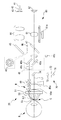
次に、図3を参照して、光学ユニット10に設けられた光学系を説明する。光学ユニット10は、撮影光学系30を少なくとも有している。また、本実施例では、更に、固視光学系70を有している。
次に、図3を参照して、光学ユニット10に設けられた光学系を説明する。光学ユニット10は、撮影光学系30を少なくとも有している。また、本実施例では、更に、固視光学系70を有している。
便宜上、まず、固視光学系70を説明する。固視光学系70は、少なくとも、固視光源(固視標)71を、有する。また、図3において、固視光学系70は、更に、アパーチャ72、レンズ73、および、ミラー74、を有する。光源71から出射された光は、アパーチャ72を介して、レンズ73を通過することで、所定の光束径でコリメートされる。コリメートされた光が、ミラー74によって折り曲げられて、被検眼Eに対して投影される。図3では、固視光学系70の光軸(より詳細には、固視光学系70の光軸のうち、ミラー74から被検眼Eまでの範囲)を、L1の符号で表す。また、L1を、固視光軸と称する。図3に示す撮影光学系30の各部材は、固視光軸を基準として配置されている。
撮影光学系30は、投光光学系40と、受光光学系60と、を有する。また、撮影光学系30は、撮影光軸L2を有する。撮影光軸L2は、固視光軸L1に対して傾斜配置され、且つ、被検眼Eの隅角へ向かう。
投光光学系40は、例えば、対物反射部50を少なくとも有する。また、実施例において、投光光学系40は、光源41、レンズ42、アパーチャ43、レンズ44、ミラー45、リングアパーチャ46、穴開きミラー47、光偏心部48、レンズ49などを有している。
光源41は、隅角に照射される照明光の光源である。本実施例において、光源41は、可視光を出射する。以下の説明では、隅角画像をカラー画像として得るために、波長域が異なる複数色の光(例えば、白色光)を、少なくとも出射可能であるものとする。
光源41からの光(照明光)は、レンズ42、アパーチャ43、レンズ44、ミラー45、リングアパーチャ46、および、穴開きミラー47、を経由して、光偏心部48に入射される。
ここで、リングアパーチャ46は、撮影光学系30の内部での反射による迷光Mを抑制するために設けられている。例えば、レンズ48c,レンズ49等の光源41側の表面による反射が、リングアパーチャ46によって抑制される。
また、穴開きミラー47は、投光光学系40と、受光光学系60との光路を分岐させる光路分岐部の一例である。穴開きミラー47に代えて、ハーフミラー等の他のビームスプリッタが適用されてもよい。本実施例では、光源41からの光は、穴開きミラー47の鏡面によって、光偏心部48に向かうように反射される。
なお、本実施例では、穴開きミラー47で反射された照明光の光路中心が、固視光軸L1と同軸となっている。
光偏心部48は、照明光の光路を、固視光軸L1に対して偏心させる。例えば、平行に配置された2枚のミラー48a,48bを用いて照明光の光路中心を、固視光軸L1に対して所定間隔だけ、シフトする。シフトされた照明光は、レンズ48cを通過して、光偏心部48から外に照射され、レンズ49を介して対物反射部50に入射する。本実施例において、レンズ49および対物反射部50のそれぞれの光軸は、固視光軸L1と同軸に配置されている。したがって、シフトされた照明光は、レンズ49および対物反射部50の光軸からも所定間隔だけ離れた領域(周辺領域As)を通る。
レンズ49は、マイナスパワーを持つレンズであり、光偏心部48から、固視光軸L1と略平行に出射される照明光を、固視光軸L1から離れる向きに折り曲げて、対物反射部50に入射させる。
対物反射部50は、照明光を、固視光軸L1側に折り曲げる反射面を持つ。反射面によって反射された照明光の光軸を、固視光軸L1に対して大きく傾斜するように折り曲げて、装置外部に導く。このとき、装置外部へ導かれる光軸が、本実施例における撮影光軸L2として利用される。装置からの照明光は、撮影光軸L2に沿って、被検眼Eの隅角領域へ照射される。
本実施例において、対物反射部50には、複数枚の反射面が、光軸周りに並べられて配置されている。対物反射部50の具体例として、本実施例では、例えば、正多角形を底面に持つ、錐台形状のプリズムが利用されるものとする。より詳細には、底面は、正16角形であり、16枚の側面を有するプリズムが利用される。本実施形態では、被検眼Eからみて、0°、22.5°、45°、67.5°、90°・・・(中略)…337.5°の各方向に、固視光軸L1に向けられた反射面が配置されている。なお、各々の角度は、固視光軸L1を基準とした角度である。また、説明の便宜上、0°は、水平面上とする。
但し、反射面は、複数枚に分かれている必要は、必ずしもなく、一連の曲面で形成されていてもよい。また、対物反射部50は、必ずしもプリズムである必要はなく、例えば、反射鏡であってもよい。反射鏡の場合、光軸側に反射面を持つ、筒状の多面鏡または曲面鏡であってもよい。
ここで、本実施例の眼科装置1は、光偏心部48を、固視光軸L1の周りに回転させる駆動部48dを有する。光偏心部48の回転に応じて、レンズ49および対物反射部50に対する照明光の入射位置が、固視光軸L1の周りに回転される。その結果、撮影光軸L2が固視光軸L1の周りに回転され、結果として、隅角の全周における照明光の照射位置が、変位される。
本実施例では、対物反射部50(プリズム)と、角膜と、の間に、ジェルGが介在される。ジェルGは、照明光の角膜反射を抑制するために、角膜へ塗布等される。なお、ジェルGは、図示なき保持容器に充填された状態で、角膜および対物反射部50の先端の両方に、接していてもよい(詳細は、本出願人による「特開2002-17680号公報」等を参照)。
投光光学系40が照射した照明光は、隅角領域で反射され、撮影光軸L2を辿って装置内部の受光光学系60へ導かれる。
本実施例において、受光光学系60は、撮像素子(受光素子の一例)62を、少なくとも有する。また、受光光学系60は、対物反射部50、および、穴開きミラー(ビームスプリッタ)47を、投光光学系40と少なくとも共用する。更に、光偏心部48、レンズ49、等を、を投光光学系40と共用していてもよい。また、受光光学系60は、フォーカスレンズ61を有する。フォーカスレンズ61は、本実施例の撮影光学系30におけるフォーカス変更部の一部である。フォーカスレンズ61を光軸に沿って移動させる駆動部61aが、眼科装置1には設けられている。駆動部61aは、例えば直動アクチュエータを含んでいてもよい。
隅角領域からの反射光は、対物反射部50、レンズ49、および、光偏心部48を介して、穴開きミラー47へ照射される。その後、反射光は、穴開きミラー47の開口、および、フォーカスレンズ61、をそれぞれ通過して、撮像素子62において結像される。結果、隅角の全周において照明光が照射された部位を撮像位置とする、隅角画像が、撮像素子62からの受光信号に基づいて得られる。
また、光偏心部48を回転させ、撮影光軸L2を固視光軸L1の周りに回転させることにより、隅角の全周における撮像位置を切換えることができる。前述したように、本実施例では、対物反射部50が、16枚の反射面を有するので、隅角の全周を16分割してその各々を、選択的に撮像できる。
<遮光部>
本実施例の対物反射部50およびレンズ49には、遮光部が設けられる。遮光部は、対物反射部50またはレンズ49などにおいて、照明光が拡散または反射することによって生じる迷光M(図3参照)の発生を抑制し、迷光Mが被検眼の眼底に入射することを防ぐ。
本実施例の対物反射部50およびレンズ49には、遮光部が設けられる。遮光部は、対物反射部50またはレンズ49などにおいて、照明光が拡散または反射することによって生じる迷光M(図3参照)の発生を抑制し、迷光Mが被検眼の眼底に入射することを防ぐ。
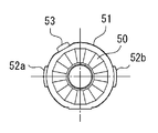
図4Aは対物反射部50を被検者側から見たときの様子、図4Bは対物反射部50をレンズ49側から見たときの様子を示す。図4Bに示すように、遮光部50aは、照明光の通過する周辺領域B1ではなく、照明光の通過しない中央領域A1に設けられる。また、本実施例の遮光部50aは環状であり、中央に開口部50bが設けられる。開口部50bは、固視光源71からの光を通過させるために設けられる。つまり、遮光部50aは、光軸L1と光軸L2の間の環状領域に設けられる。
図5は、レンズ49を被検者側から見たときの様子を示す。レンズ49の遮光部49aは、遮光部50aと同様に、照明光の通過する周辺領域B2ではなく、照明光の通過しない中央領域A2に設けられる。遮光部49aの中央にも固視光源71からの光を通過させるために、開口部49bが設けられている。
本実施例において、遮光部49aおよび遮光部50aは、黒色の印刷である。黒色の印刷によって、撮影光学系30の内部で予期せぬ方向に反射または拡散した照明光(迷光M)が遮光され、被検眼の眼底に入射する迷光Mを減少させる。これによって、被検者にまぶしさを感じさせることを防止できる。
もちろん、遮光部49aまたは遮光部50aは、遮光できる構成であればよく、黒色の印刷に限らない。例えば、他の色の印刷であってもよいし、印刷ではなく塗装またはコーティングであってもよい。例えば、遮光部49a,50aは、黒クロム(酸化クロム)のコーティングによって形成されてもよい。また、遮光部49a,50aは、フィルムまたはシールによって形成されてもよい。
なお、遮光部49a,50aは、円形であってもよいし、図6に示すような多角形でもよい。遮光部49a,50aは、照明光束と固視光束を遮らないような形状であればよい。
なお、遮光部は、対物反射部50およびレンズ49の両方に設ける必要はなく、どちらか一方だけでもよい。
<対物反射部の装着>
なお、対物反射部50は、被検眼Eとの間にジェルGを介在させて近接させるため、撮影毎に交換し易いように先端部11から取り外しできるようになっている。例えば、本実施例では、先端部11に装着部(後述する)が設けられ、装着部に対物反射部50を装着できるようになっている。詳細には、ホルダ51に保持された対物反射部50がホルダ51とともに装着部に装着される。
なお、対物反射部50は、被検眼Eとの間にジェルGを介在させて近接させるため、撮影毎に交換し易いように先端部11から取り外しできるようになっている。例えば、本実施例では、先端部11に装着部(後述する)が設けられ、装着部に対物反射部50を装着できるようになっている。詳細には、ホルダ51に保持された対物反射部50がホルダ51とともに装着部に装着される。
図4に示すように、対物反射部50は、ホルダ51に保持される。ホルダ51には、凸部52a,52bおよび凸部53が設けられる。凸部52a,52bは、例えば、ホルダ51の左右に設けられており、検者がホルダ51を持つときの把持部として機能する。凸部53は、例えば、ホルダ51の形状が、どの経線に対しても非対称な位置に設けられる。つまり、凸部53は、装着部の形状が線対称とはならない位置に配置される。本実施例のように凸部52a,凸部52bが左右対称に設けられている場合、凸部53は、左右対称軸V1から外れた位置に設けられる。例えば、本実施例の凸部53は、光軸回りの水平軸Hからの角度αが60°となる位置に設けられる。
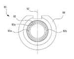
図7は、先端部11の先端に設けられる装着部90の概略図である。装着部90には、対物反射部50を保持するホルダ51が装着される。装着部90は、図3の撮影光学系30において、レンズ49と対物反射部50の間に設けられる。
装着部90は、例えば、円筒部91と嵌合部95などを有する。嵌合部95は、例えば、ホルダ51の一部と嵌合することによって、ホルダ51を保持する。嵌合部95は、例えば、切欠き92a,92b、切欠き93などである。切欠き92a,92bは、円筒部91の周縁の左右に設けられる。切欠き93は、装着部90の形状が、どの経線に対しても非対称な位置に設けられる。本実施例のように、切欠き92a,92bが左右対称に設けられている場合、凸部53は、左右対称軸V2から外れた位置に設けられる。
図8Aはホルダ51が装着される前の装着部90の斜視図であり、図8Bはホルダ51が装着された後の装着部90の斜視図である。本実施例の場合、図8Bに示すように、切欠き92aは凸部52aと嵌合し、切欠き92bは凸部52bと嵌合し、切欠き93は凸部53と嵌合する。このように、ホルダ51の各凸部52a,52b,53が、装着部90の各切欠き92a,92b,93と嵌合することによって、ホルダ51に保持された対物反射部50の姿勢が規制される。また、装着部90にホルダ51が装着されることによって、対物反射部50の位置が定まる。
上記のように、対物反射部50の姿勢が規制されることによって、対物反射部50に設けられた複数の反射面が所定の位置に配置される。これによって、所定の撮影位置で隅角を撮影することができる。仮に対物反射部50の角度がずれてしまうと、隅角の撮影位置がずれてしまう。本実施例のように、嵌合部95によって対物反射部50の姿勢を規制することで、対物反射部50を正しい角度で装着部90に取り付けることができる。
また、本実施例のように、装着部の切欠きと、ホルダの凸部がそれぞれ3つ備わり、それらが線対称とならない位置に配置される場合、対物反射部50の表裏が反対に装着されることがなくなる。例えば、対物反射部50の裏表を判定に装着しようとした場合、切欠き92aと凸部52bが嵌合し、切欠き92bと凸部52aが嵌合するが、切欠き93と凸部53は位置がずれるため、嵌合しない。
仮に、切欠き93および凸部53が左右対称軸上に設けられた場合、対物反射部50を表裏反転させた状態で装着部90に取り付けることができる。つまり、切欠き92aと凸部52bが嵌合し、切欠き92bと凸部52aが嵌合し、切欠き93と凸部53が嵌合する。しかしながら、対物反射部50の裏表が反対である場合、隅角を上手く撮影することができない。したがって、本実施例のように、嵌合部95を3つ設け、それらを線対称とならない位置に配置することによって、対物反射部50を表裏逆に装着できないようにし、撮影ミスの発生を防止することができる。
なお、本実施例において、装着部90とホルダ51は、簡単に外れないように磁力による引力を働かせている。例えば、装着部90は磁石93aを備え、ホルダ51は磁石53aを備えている。もちろん、磁石93a,53aの一方は鉄などの磁性体であってもよい。
なお、本実施例において、ホルダ51の凸部と装着部90の切欠きの数はそれぞれ3つであったが、1つであってもよい。切欠きおよび凸部が1つであっても、対物反さY部50の回転方向は規制できる。
なお、本実施例において、嵌合部95は、切欠きであったが、ホルダ51の凸部と嵌合する凹部であってもよい。もちろん、ホルダ51に凹部が設けられる場合、嵌合部95は凸部であってもよい。
<制御系>
次に、図9を参照して、眼科装置1の制御系を説明する。眼科装置1は、制御部(プロセッサ)80を備える。制御部80によって、装置全体の制御処理および各種演算処理が実行される。
次に、図9を参照して、眼科装置1の制御系を説明する。眼科装置1は、制御部(プロセッサ)80を備える。制御部80によって、装置全体の制御処理および各種演算処理が実行される。
制御部80は、CPU、ROM、RAM等を含んでいてもよい。RAMには、例えば、撮影および測定に用いる一時データが格納される。
制御部80は、例えば、バス等を介して、アライメント機構5a,5b、モニタ8、光源41、駆動部48d、駆動部61a、受光素子62、光源71、記憶装置81、操作部85、等と接続される。
記憶装置81は、書き換え可能な不揮発性の記憶装置である。記憶装置81としては、ハードディスク、フラッシュメモリ、USBメモリ等の種々の記憶装置が適用可能である。また、記憶装置81には、例えば、眼科装置1に撮影動作等の各種動作を実行させるためのプログラムが、少なくとも格納されていてもよい。
眼科装置1によって撮像される隅角画像は、記憶装置81に保存されてもよい。また、モニタ8において表示されてもよい。
操作部85は、眼科装置1における入力インターフェイスである。操作部85が検者によって操作されることによって、操作に応じた指示が、制御部80に入力される。操作部85としては、例えば、マウス、および、タッチパネル等のポインティングデバイスであってもよいし、キーボードであってもよい。また、眼科装置1において、アライメントのために操作されるジョイスティック7が、操作部85の1つとして利用されてもよい。
<動作説明>
以上のような構成を持つ、眼科装置1における隅角画像の撮影動作を説明する。
以上のような構成を持つ、眼科装置1における隅角画像の撮影動作を説明する。
撮影に際し、まず、制御部80は、光源71を点灯し、固視標の投影を開始する。これにより、被検眼Eの視線が誘導される。
次に、検者は、ジョイスティック7等を操作して、対物反射部50の先端が、被検眼Eの角膜から数ミリ程度の距離となるように、撮影光学系30を被検眼Eへと接近させる(第1のアライメント)。その際、併せて、被検眼Eと対物反射部50との間に、ジェルGを介在させる。
第1のアライメントが完了した後、第2のアライメントが実行される。例えば、第1のアライメント完了を、装置が自動で検出して、第2のアライメントが開始してもよいし、操作部85に対する所定の操作の入力をトリガとして、第2のアライメントが開始されてもよい。
ここで、第1のアライメント完了を、自動的に検出する場合の一例を示す。例えば、制御部80は、予め定められた複数の撮像位置で隅角画像を、検者によってジョイスティック7等が操作される間、繰り返し撮像する。そして、各々の隅角画像を処理して、その隅角画像において隅角の特徴部が含まれているか否かを検出する。より詳細には、各々の隅角画像の中に、隅角の特徴部を示す画像的な特徴が含まれているか否かを確認する。各撮像位置での隅角画像において隅角の特徴部が検出される場合に、第1のアライメントを完了してもよい。第1のアライメント完了を判定する際に利用される特徴部は、後述の第2のアライメントに利用される特徴部と同一であってもよい。
第2のアライメントでは、隅角全周の中心に、対物反射部50の光軸が略合致するように、被検眼Eと撮影光学系30との位置関係が調整される。より詳細には、光偏心部48の回転によって互いに異なる撮像位置で隅角画像を得た際に、それぞれの隅角画像において所定の特徴部が良好に含まれるように、調整が行われる。
線維柱帯は、虹彩と角膜の間にある。角膜の方が虹彩に比べ、可視光を反射しやすいため、隅角画像において線維柱帯の近傍には、大きな輝度の変化が確認される。における線維柱帯の位置を特定(検出)してもよい。
撮影された隅角画像を、制御部80は、モニタ8へ表示させてもよい。この場合、図10に示すレイアウトで、16枚の隅角画像を並べて表示させてもよい。即ち、各々の隅角画像を撮影部位の位置と対応させつつ、円環状に並べて配置させる。これにより、隅角の全周における線維柱帯の状態を、検者に容易に確認させることができる。
以上、実施形態に基づいて本開示を説明したが、本開示は、上記形態に限定されるものではなく、種々の変容が可能である。
1 眼科装置
4,5a,5b アライメント機構
30 撮影光学系
40 投光光学系
48 光偏心部
50 対物光学系
60 受光光学系
61 フォーカシングレンズ
61a 駆動部
80 制御部
4,5a,5b アライメント機構
30 撮影光学系
40 投光光学系
48 光偏心部
50 対物光学系
60 受光光学系
61 フォーカシングレンズ
61a 駆動部
80 制御部
Claims (23)
- 被検眼の隅角を撮影する眼科装置であって、
被検眼の隅角へ照明光を投光する投光光学系と、
前記隅角からの反射光を受光する受光素子を有する受光光学系と、を備え、
前記投光光学系の少なくとも一部の光学素子に遮光部が設けられることを特徴とする眼科装置。 - 前記遮光部は、前記光学素子において、前記照明光が通過する周辺領域よりも内側に位置する中央領域に設けられることを特徴とする請求項1の眼科装置。
- 前記遮光部は、中央に開口部を有する環状であることを特徴とする請求項1または2の眼科装置。
- 固視光源からの固視光束を前記被検眼に投光する固視光学系をさらに備え、
前記固視光束は、前記開口部を介して前記被検眼に入射することを特徴とする請求項3の眼科装置。 - 前記投光光学系は、光軸方向において隣り合う第1光学素子と第2光学素子を備え、
前記遮光部は、前記第1光学素子および前記第2光学素子の対面側にそれぞれ設けられることを特徴とする請求項1~4のいずれかの眼科装置。 - 前記遮光部は、黒色の印刷によって形成されることを特徴とする請求項1~5のいずれかの眼科装置。
- 前記遮光部は、コーティングによって形成されることを特徴とする請求項1~5のいずれかの眼科装置。
- 前記遮光部は、塗装によって形成されることを特徴とする請求項1~5のいずれかの眼科装置。
- 前記光学素子は、前記被検眼に対して前面側に反射面を有し、後面側に透光面を有することを特徴とする請求項1の眼科装置。
- 被検眼の隅角を撮影する眼科装置において用いられる光学素子であって、
前記光学素子の前面側に設けられた反射面と、
前記光学素子の後面側に設けられた透光面と、
前記透光面に設けられた遮光部と、を備えることを特徴とする光学素子。 - 被検眼の隅角を撮影する眼科装置であって、
被検眼の隅角へ照明光を投光する投光光学系と、
前記投光光学系の光軸上に挿入される光学素子を装着可能な装着部と、を備え、
前記装着部は、前記光学素子の姿勢を規制する規制手段を備えることを特徴とする眼科装置。 - 前記規制手段は、前記光学素子の光軸回りの回転角度を規制することを特徴とする請求項11の眼科装置。
- 前記光学素子は、複数の反射面を有し、
前記規制手段は、前記反射面が所定方向を向くように前記光学素子の姿勢を規制することを特徴とする請求項11または12の眼科装置。 - 前記規制手段は、前記光学素子を保持するホルダの一部と嵌合することによって、前記光学素子の姿勢を規制する嵌合部を備えることを特徴とする請求項11~13のいずれかの眼科装置。
- 前記装着部は、筒状であり、
前記嵌合部は、前記装着部に設けられた切欠きであることを特徴とする請求項14の眼科装置。 - 前記嵌合部は、凹部であることを特徴とする請求項14の眼科装置。
- 前記装着部は、2以上の嵌合部を備えることを特徴とする請求項14の眼科装置。
- 前記嵌合部は、前記装着部の形状がどの経線に対しても非対称な位置に配置されることを特徴とする請求項14~17のいずれかの眼科装置。
- 前記嵌合部は、前記ホルダに設けられた把持部と嵌合することを特徴とする請求項14~17のいずれかの眼科装置。
- 前記規制手段は、前記光学素子を保持するホルダ全体と嵌合することによって、前記光学素子の姿勢を規制する嵌合部を備えることを特徴とする請求項11~13のいずれかの眼科装置。
- 前記嵌合部および前記ホルダは、多角形状であることを特徴とする請求項20の眼科装置。
- 前記装着部は、前記ホルダを保持するための磁性体を備えることを特徴とする請求項11~19のいずれかの眼科装置。
- 被検眼の隅角を撮影する眼科装置において用いられる光学素子であって、
前記光学素子の前面側に設けられた反射面と、
前記光学素子の後面側に設けられた透光面と、を備え、
請求項11~22の前記装着部に装着されることを特徴とする光学素子。
Applications Claiming Priority (4)
| Application Number | Priority Date | Filing Date | Title |
|---|---|---|---|
| JP2017091344A JP7009776B2 (ja) | 2017-05-01 | 2017-05-01 | 眼科装置、およびそれに用いる光学素子 |
| JP2017-091343 | 2017-05-01 | ||
| JP2017-091344 | 2017-05-01 | ||
| JP2017091343A JP7009775B2 (ja) | 2017-05-01 | 2017-05-01 | 眼科装置、およびそれに用いる光学素子 |
Publications (1)
| Publication Number | Publication Date |
|---|---|
| WO2018203529A1 true WO2018203529A1 (ja) | 2018-11-08 |
Family
ID=64016184
Family Applications (1)
| Application Number | Title | Priority Date | Filing Date |
|---|---|---|---|
| PCT/JP2018/017211 Ceased WO2018203529A1 (ja) | 2017-05-01 | 2018-04-27 | 眼科装置、およびそれに用いる光学素子 |
Country Status (1)
| Country | Link |
|---|---|
| WO (1) | WO2018203529A1 (ja) |
Cited By (1)
| Publication number | Priority date | Publication date | Assignee | Title |
|---|---|---|---|---|
| JP2023500184A (ja) * | 2019-10-29 | 2023-01-05 | ヴェリリー ライフ サイエンシズ エルエルシー | 網膜カメラ用の外部位置合わせ表示/誘導システム |
Citations (3)
| Publication number | Priority date | Publication date | Assignee | Title |
|---|---|---|---|---|
| JPH0515493A (ja) * | 1991-07-05 | 1993-01-26 | Toomee:Kk | 眼内観察用コンタクトレンズ |
| JP2013212313A (ja) * | 2012-04-03 | 2013-10-17 | Canon Inc | 光干渉断層撮影装置、制御方法、及びプログラム |
| WO2015180923A1 (en) * | 2014-05-30 | 2015-12-03 | Nidek Co. Ltd | Optical equipment for observation of the iridocorneal zone, methods of measuring and/or evaluating the iridocorneal zone |
-
2018
- 2018-04-27 WO PCT/JP2018/017211 patent/WO2018203529A1/ja not_active Ceased
Patent Citations (3)
| Publication number | Priority date | Publication date | Assignee | Title |
|---|---|---|---|---|
| JPH0515493A (ja) * | 1991-07-05 | 1993-01-26 | Toomee:Kk | 眼内観察用コンタクトレンズ |
| JP2013212313A (ja) * | 2012-04-03 | 2013-10-17 | Canon Inc | 光干渉断層撮影装置、制御方法、及びプログラム |
| WO2015180923A1 (en) * | 2014-05-30 | 2015-12-03 | Nidek Co. Ltd | Optical equipment for observation of the iridocorneal zone, methods of measuring and/or evaluating the iridocorneal zone |
Cited By (2)
| Publication number | Priority date | Publication date | Assignee | Title |
|---|---|---|---|---|
| JP2023500184A (ja) * | 2019-10-29 | 2023-01-05 | ヴェリリー ライフ サイエンシズ エルエルシー | 網膜カメラ用の外部位置合わせ表示/誘導システム |
| JP7378603B2 (ja) | 2019-10-29 | 2023-11-13 | ヴェリリー ライフ サイエンシズ エルエルシー | 網膜カメラ用の外部位置合わせ表示/誘導システム |
Similar Documents
| Publication | Publication Date | Title |
|---|---|---|
| JP4937792B2 (ja) | 眼底カメラ | |
| US8931901B2 (en) | Ophthalmologic apparatus | |
| JP6003292B2 (ja) | 眼底撮影装置 | |
| JP6930095B2 (ja) | 自覚式検眼装置 | |
| JP5772117B2 (ja) | 眼底撮影装置 | |
| JP5403235B2 (ja) | 角膜内皮検査装置 | |
| JP5386759B2 (ja) | 角膜内皮検査装置 | |
| JP4119035B2 (ja) | 角膜形状測定装置 | |
| TWI480021B (zh) | Assist in gaze focusing on the fundus detection device | |
| WO2018203529A1 (ja) | 眼科装置、およびそれに用いる光学素子 | |
| JP6798287B2 (ja) | 自覚式検眼装置 | |
| JP7283391B2 (ja) | 眼屈折力測定装置 | |
| JP7009775B2 (ja) | 眼科装置、およびそれに用いる光学素子 | |
| JP2001340301A (ja) | 眼底撮影装置 | |
| JP7009776B2 (ja) | 眼科装置、およびそれに用いる光学素子 | |
| CN115460970B (zh) | 眼底摄影装置 | |
| JP7009774B2 (ja) | 模型眼 | |
| JP2020069271A (ja) | 眼科撮影装置 | |
| JP3798159B2 (ja) | 前眼部断面像撮影装置 | |
| JP4492854B2 (ja) | 眼底カメラ | |
| JP5199008B2 (ja) | 眼底カメラ | |
| JP2021062162A (ja) | 走査型眼底撮影装置 | |
| JP7666140B2 (ja) | 走査型眼底撮影装置 | |
| JP2013179979A (ja) | 眼底撮影装置 | |
| JP5927689B2 (ja) | 眼科用検査装置 |
Legal Events
| Date | Code | Title | Description |
|---|---|---|---|
| 121 | Ep: the epo has been informed by wipo that ep was designated in this application |
Ref document number: 18794146 Country of ref document: EP Kind code of ref document: A1 |
|
| NENP | Non-entry into the national phase |
Ref country code: DE |
|
| 122 | Ep: pct application non-entry in european phase |
Ref document number: 18794146 Country of ref document: EP Kind code of ref document: A1 |