WO2018202033A1 - 喷墨打印设备以及喷墨打印方法 - Google Patents
喷墨打印设备以及喷墨打印方法 Download PDFInfo
- Publication number
- WO2018202033A1 WO2018202033A1 PCT/CN2018/085307 CN2018085307W WO2018202033A1 WO 2018202033 A1 WO2018202033 A1 WO 2018202033A1 CN 2018085307 W CN2018085307 W CN 2018085307W WO 2018202033 A1 WO2018202033 A1 WO 2018202033A1
- Authority
- WO
- WIPO (PCT)
- Prior art keywords
- structural portion
- liquid
- control signal
- control
- nozzles
- Prior art date
- Legal status (The legal status is an assumption and is not a legal conclusion. Google has not performed a legal analysis and makes no representation as to the accuracy of the status listed.)
- Ceased
Links
Images




Classifications
-
- B—PERFORMING OPERATIONS; TRANSPORTING
- B41—PRINTING; LINING MACHINES; TYPEWRITERS; STAMPS
- B41J—TYPEWRITERS; SELECTIVE PRINTING MECHANISMS, i.e. MECHANISMS PRINTING OTHERWISE THAN FROM A FORME; CORRECTION OF TYPOGRAPHICAL ERRORS
- B41J2/00—Typewriters or selective printing mechanisms characterised by the printing or marking process for which they are designed
- B41J2/005—Typewriters or selective printing mechanisms characterised by the printing or marking process for which they are designed characterised by bringing liquid or particles selectively into contact with a printing material
- B41J2/01—Ink jet
- B41J2/135—Nozzles
- B41J2/14—Structure thereof only for on-demand ink jet heads
- B41J2/14201—Structure of print heads with piezoelectric elements
-
- B—PERFORMING OPERATIONS; TRANSPORTING
- B41—PRINTING; LINING MACHINES; TYPEWRITERS; STAMPS
- B41J—TYPEWRITERS; SELECTIVE PRINTING MECHANISMS, i.e. MECHANISMS PRINTING OTHERWISE THAN FROM A FORME; CORRECTION OF TYPOGRAPHICAL ERRORS
- B41J2/00—Typewriters or selective printing mechanisms characterised by the printing or marking process for which they are designed
- B41J2/005—Typewriters or selective printing mechanisms characterised by the printing or marking process for which they are designed characterised by bringing liquid or particles selectively into contact with a printing material
- B41J2/01—Ink jet
- B41J2/07—Ink jet characterised by jet control
- B41J2/11—Ink jet characterised by jet control for ink spray
-
- B—PERFORMING OPERATIONS; TRANSPORTING
- B41—PRINTING; LINING MACHINES; TYPEWRITERS; STAMPS
- B41J—TYPEWRITERS; SELECTIVE PRINTING MECHANISMS, i.e. MECHANISMS PRINTING OTHERWISE THAN FROM A FORME; CORRECTION OF TYPOGRAPHICAL ERRORS
- B41J2202/00—Embodiments of or processes related to ink-jet or thermal heads
- B41J2202/01—Embodiments of or processes related to ink-jet heads
Definitions
- Embodiments of the present application relate to an inkjet printing apparatus and an inkjet printing method.
- the engineer observes the coated film surface on a macroscopic microscopic inspection machine, and after subjective judgment, then manually adjusts the voltage corresponding to each nozzle, and so on, until the film surface is adjusted to an acceptable level.
- this manual manual adjustment method takes a long time, and the material and manpower are wasteful; and because the adjustment method is subjective, the PI film thickness unevenness is often followed.
- an embodiment of the present disclosure provides an inkjet printing apparatus including: a plurality of nozzles and a control member coupled to the plurality of nozzles, wherein each of the nozzles includes: a first structural portion, and the a second structural portion connected to the first structural portion, a liquid inlet provided in the first structural portion, and a liquid outlet provided in the second structural portion; the first structural portion is configured to receive the Delivering liquid to the second structural portion when the first control signal sent by the control unit is sent; and delivering the third to the second structural portion when receiving the third control signal sent by the control unit Controlling a corresponding amount of liquid; the second structural portion is configured to meter the liquid it contains and to transmit the metered value to the control component, and upon receiving the second control signal transmitted by the control component Printing the liquid onto the target substrate; the control component being configured to, when determining to begin printing, transmitting the first control signal to the first structural portion of each of the nozzles; and determining the received plurality of One Sending a second control signal to the second
- control component calculates a difference between the metering value of the nozzle and an intermediate value of the first predetermined range, and according to the difference to the first structure of the nozzle
- the portion transmits a third control signal that matches the difference.
- control component calculates a difference between the metering value of the nozzle and a maximum value of the first predetermined range, and according to the difference to the first structure of the nozzle The portion transmits a third control signal that matches the difference.
- the third control signal is a voltage signal
- the first structural portion includes a cavity open at both ends surrounded by a sidewall of piezoelectric ceramic, and one end of the cavity is opened as the a liquid port, the other end opening of the cavity is opposite to the second structural portion; the first structural portion is configured to generate a corresponding volume expansion according to a magnitude of the voltage signal when the voltage signal is received And contracting when the voltage signal is removed to deliver a liquid corresponding to the third control signal to the second structural portion.
- the piezoelectric ceramic is made of quartz, sodium potassium tartrate or ammonium dihydrogen phosphate.
- the second structural portion includes: a body and a weighing component movably coupled to the body; the second structural portion is configured to: when the second control signal is not received, The weighing component is adjusted to the first position to form a cavity that is closed at one end with the body; and when the second control signal is received, the weighing component is adjusted to the second position to form the liquid outlet .
- the body is frame-shaped, including a first sidewall and a second sidewall and a third sidewall connected to the first sidewall opposite to each other, and the end of the first sidewall is disposed a reel having end portions of the second side wall and the third side wall respectively provided with strip-shaped concave chutes, the planes of the two concave chutes being parallel to the cross section of the body;
- the weighing The component is formed as a roller blind structure comprising a plurality of movably serially connected sub-pieces, one end of the roller blind structure being coupled to the reel, and two ends of each of the sub-sheets being respectively located in the two concave shapes Inside the chute, such that the sub-sheet is movable along the two concave chutes and rotated about the reel so that the roller blind structure can be deployed to enter the first position or retract to enter the Second position.
- the body is frame-shaped, including a first sidewall and second and third sidewalls opposite to each other connected to the first sidewall, the second sidewall and the third sidewall
- the ends of the wall are respectively provided with strip-shaped concave sliding grooves, and the planes formed by the two concave sliding grooves are parallel to the cross section of the body;
- the weighing member is formed as a flat plate, and both ends of the flat plate Located in the two concave chutes respectively, such that the flat plate can slide along the two concave chutes toward the first side wall to enter the first position or away from the first side The wall slides to enter the second position.
- the weighing member is formed as a rotating flap having a connecting end and a rotating end, the connecting end being movably connected with the second structural portion body, the rotating end being capable of surrounding the The connecting end rotates to enter the first position and the second position, respectively.
- the weighing component is integrally formed as a gravity sensing chip or a pressure sensing chip.
- each of the nozzles is further provided with an atomizing component connected to the second structural portion, the atomizing component being configured to disperse and atomize the liquid before printing the liquid onto the target substrate, The liquid can be uniformly sprayed onto the target substrate.
- the atomizing component is a centrifugal atomizer or a high pressure gas atomizer.
- control component is any one or a combination of a central processing unit, a single chip microcomputer, and a digital signal processor, or a circuit board including any one or combination of a central processing unit, a single chip microcomputer, and a digital signal processor.
- the embodiment of the present application further provides an inkjet printing method for printing by using any of the above inkjet printing apparatuses, comprising: the control component transmitting to the first structural part of each of the nozzles in response to a print command signal a first control signal; the first structural portion delivers liquid to the second structural portion in response to the first control signal; the second structural portion meters a liquid it contains and transmits the measured value to the a control component; the control component transmitting a second control signal to the second structural portion to print a liquid contained in the second structural portion to a target when it is determined that the measured value is received to satisfy the first predetermined range And transmitting, on the substrate, a third control signal to the first structural portion, the third control signal representing a liquid amount adjustment value; the first structural portion is responsive to the third control signal to the second The structure portion delivers a liquid corresponding to the liquid amount adjustment value.
- the transmitting, by the control component, the third control signal to the first structural portion includes: the control component calculating a difference between the measured value and an intermediate value of the first predetermined range, and The first structural portion transmits a third control signal that matches the difference.
- the transmitting, by the control component, the third control signal to the first structural portion includes: the control component calculating a difference between the measured value and a maximum value of the first preset range, and The first structural portion transmits a third control signal that matches the difference.
- the printing method further includes: the second The structure re-measuring the liquid it contains and transmitting a new meter value to the control component; the control component to the second structure upon determining that the new meter value is received to satisfy the first predetermined range The portion transmits a second control signal to print the liquid contained in the second structure portion onto the target substrate.
- the printing method further includes: pairing the second structural portion The contained liquid is atomized to enable the liquid to be uniformly sprayed onto the target substrate.
- the third control signal is a voltage signal
- the first structural portion in response to the third control signal, delivering a liquid corresponding to the liquid amount adjustment value to the second structural portion, includes: When receiving the voltage signal, the first structural portion generates a corresponding volume expansion according to the magnitude of the voltage signal, and shrinks when the voltage signal is removed, and further delivers the third portion to the second structural portion.
- the control signal corresponds to the amount of liquid.
- FIG. 1 is a schematic structural diagram of an inkjet printing apparatus according to an embodiment of the present application.
- FIG. 2 is a schematic structural view of a nozzle provided by an embodiment of the present application.
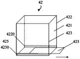
- FIG. 3 is a schematic structural view of a second structural part of a weighing component provided with a roller blind structure according to an embodiment of the present application, the roller blind structure is in an unfolded state;
- FIG. 4 is another schematic structural view of a second structural part of a weighing component provided with a roller blind structure according to an embodiment of the present application, the roller blind structure is in a contracted state;
- FIG. 5A is a schematic structural diagram of a second structural part of a weighing component provided with a sliding door structure according to an embodiment of the present application.
- FIG. 5B is a schematic structural diagram of a second structural part of a weighing component provided with a rotatable plate structure according to an embodiment of the present application.
- FIG. 6 is another structural diagram of a second structural portion of a weighing member provided with a rotatable plate structure according to an embodiment of the present application.
- FIG. 7 is a schematic structural diagram of a second structural portion provided with an atomizing component according to an embodiment of the present application.
- FIG. 8 is a flowchart of an inkjet printing method according to an embodiment of the present application.
- FIG. 9 is another flow chart of an inkjet printing method according to an embodiment of the present application.
- an embodiment of the present application provides an inkjet printing apparatus including a plurality of nozzles 4 and a control member 5 connected to each nozzle 4, wherein each nozzle 4 includes a first structural portion 41.
- the second structural portion 42 connected to the first structural portion 41, the liquid inlet 43 provided in the first structural portion 41, and the liquid outlet 44 provided in the second structural portion 42.
- the inkjet printing apparatus may further include a head 3 in which the nozzle 4 is disposed and a machine 1 configured to carry the target substrate 2, which are known in the art and will not be described herein.
- the first structural portion 41 is configured to deliver liquid to the second structural portion 42 upon receipt of the first control signal; to deliver a third control portion to the third structural portion 42 when the third control signal is received Liquid.
- the second structural portion 42 is configured to meter the liquid it contains and to transmit the metered value to the control unit 5, and to release the liquid 6 onto the target substrate 2 upon receiving the second control signal transmitted by the control unit 5.
- the control unit 5 is configured to transmit a first control signal to the first structural portion 41 of each nozzle 4 when it is determined to start printing, and when it is determined that the received measurement value of each nozzle 4 satisfies the first predetermined range, A second control signal is sent to the second structural portion 42 of each nozzle 4, otherwise a third control signal is sent to the corresponding first structural portion 42 of the nozzle 4 based on the measured value of each nozzle 4.
- the inkjet printing device has the purpose of making the amount of liquid ejected by each nozzle the same.
- the exact same amount of liquid may be difficult to achieve, in some examples, when the metering values for the individual nozzles are substantially the same, ie, when the metering values for all nozzles are within the first predetermined range , release the liquid onto the target substrate.
- the first predetermined range in the embodiment of the present application may be a range of weight values, for example, 2.01 g to 2.09 g, that is, when all the weight values of the nozzles satisfy more than 2.01 g and less than 2.09 g, all the nozzles are considered.
- the amount of liquid is substantially the same, and the amount of liquid of each nozzle can be printed on the target substrate.
- the boundary value of the specific first preset range may be set according to the actual required precision requirement in the specific implementation, and is not limited herein.
- the inkjet printing apparatus provided by the embodiment of the present application may send the same first control signal to the first structural portion of each nozzle when determining to start printing, because the amount of liquid initially delivered to the second structural portion is The smaller the difference, the smaller the adjustment of the amount of liquid in the second structural portion of each nozzle is required; thus, the amount of liquid in the second structural portion of each nozzle can be adjusted in a small number of times and in a short time so that It satisfies the first preset range.
- the time at which printing is started may be determined by the operator as needed, that is, in actual operation, the operator may press the indication button of the printing device, and the control unit determines when receiving the instruction corresponding to the indication button. Printing is started, and the first control signal is transmitted to the first component.
- the third control signal is a control signal corresponding to the measured value, ie, the amount of liquid delivered to the second structural portion according to the third control signal may cause the measured value of the second structural portion to meet or approximate The first preset range; the third signals of the respective nozzles may be the same or different.
- the second time may be performed. , third or more adjustments. If the first structural portion delivers the liquid to the second structural portion according to the third control signal, and the measured value of the second structural portion is greater than the maximum value of the first predetermined range, the printing may be terminated or a larger boundary value may be selected. The first preset range is re-adjusted.
- the inkjet printing device of the embodiment of the present invention can be used for printing the alignment liquid to the target substrate and/or printing the liquid crystal to the target substrate during the manufacturing process of the display panel, which is not limited herein.
- the embodiment of the present application designs the nozzle as a two-layer structure, the liquid is delivered to the second structural portion through the first structural portion, and then the liquid is weighed and measured by the second structural portion, and the second structural portion of each nozzle is measured.
- the liquid amount satisfies the first predetermined range, the liquid is printed on the substrate, thereby ensuring that the amount of liquid printed by each nozzle is at least substantially the same; in this way, the formation of the liquid due to the inconsistency of the liquid discharged from each nozzle can be reduced.
- the probability of printing film film thickness is not uniform.
- the first structural portion may be controlled by the control component to readjust the liquid discharge amount until the liquid amount of the second structural portion of each nozzle is satisfied.
- the liquid is printed onto the target substrate at the first predetermined range, thereby avoiding the problem of time consuming, consumables, and difficulty in adjusting uniformity when manually adjusting the amount of liquid discharged from the nozzle.
- control component is configured to calculate a difference between the measured value of each nozzle and an intermediate value of the first predetermined range according to the measured value of each nozzle, and respectively to the first of each nozzle according to the difference
- the structure unit transmits a third control signal that matches the difference.
- the intermediate value may be an average value of two side values of the first preset range.
- the first preset range is 2.01 g to 2.09 g
- the middle value is an average value of two side values.
- the control signal can send a voltage signal of 0.07V to the first structural portion, and the first structural portion can be obtained according to the obtained 0.07
- the voltage value of V prints a liquid corresponding to a voltage of 0.07 V to the second structural portion.
- the amount of liquid of the second structural portion of each nozzle can be controlled to be within the first predetermined range with a small number of adjustments and at a short time.
- the amount of liquid in the second structural portion of each nozzle can be controlled by the other calculation method in the first predetermined range.
- the embodiment of the present application is not limited herein.
- a difference between the measured value of the second structural portion and the maximum value of the first predetermined range may also be calculated, and a corresponding control signal is transmitted to the first structural portion based on the difference.
- the first structural portion may include a cavity surrounded by sidewalls of piezoelectric ceramic and open at both ends, and one end of the cavity is opened as a liquid inlet, the cavity The other end opening is opposite to the second structural portion.
- the first structural portion expands corresponding volume according to the magnitude of the voltage signal, and shrinks when the voltage signal is removed, and further delivers a quantity corresponding to the third control signal to the second structural portion. liquid. In the expansion and contraction of the nozzle, fine drip control of the liquid is achieved.
- the first structural portion can be constituted, for example, of a material that can be expanded and contracted by voltage control, thereby conveniently and accurately controlling the amount of liquid delivered to the second structural portion.
- the material of the piezoelectric ceramic constituting the side wall of the first structural portion may be quartz, sodium potassium tartrate or ammonium dihydrogen phosphate.
- the structure and material of the first structural portion may be the same as that of the ink jet printing device of the prior art.
- the second structural portion of the embodiment of the present application may include, for example, a second structural portion body, and a positionally adjustable weighing member disposed at the second structural portion body.
- the second structural portion can adjust the weighing component to the first position to perform weighing measurement on the contained liquid; and adjust the weighing component to not block the liquid when receiving the second control signal
- the second position is to facilitate release of the liquid onto the target substrate. That is, in the present embodiment, the weighing member can be used for both liquid weight measurement and liquid release. The measurement and release of the liquid can be accomplished by adjusting the weighing components to different locations on the body of the second structural portion.
- Embodiments of the present application do not specifically define the first and second positions described above, as long as the first position allows the liquid to be weighed and the second position does not obstruct the liquid drop during the liquid drop to the target substrate.
- the weighing member may be a member that can be contracted or translated, a rotatable member, or the like.
- the second structural portion body is frame-shaped and includes first to third side walls 421-423.
- the end of the first side wall 421 (for example, the lower end as shown in FIGS. 3-4) is provided with a reel 424; at the ends of the two side walls adjacent to the first side wall 421, a strip-shaped recess is provided
- the second side wall 422 is provided with a first concave sliding groove 4220, and the third side wall 423 is provided with a second concave sliding groove 4230.
- the planes of the two concave sliding grooves are parallel.
- the weighing member is formed as a roller blind structure, and is formed by a plurality of sub-sheets 425 being cascaded along the width direction of the sub-sheet 425 (ie, the horizontal direction in FIG. 3); the roller blind structure One end (for example, the right end of the roller blind structure shown in Fig. 3) is coupled to the reel 424; both ends of each sub-sheet 425 (e.g., the ends of each sub-sheet 425 shown in Fig. 3 perpendicular to the plane of the paper) are respectively located.
- the concave grooves 4220, 4230 of the second side wall 422 and the third side wall 423 are movable along the concave chutes 4220, 4230 and around the reel 424 to cause the roller blind structure to expand into the manner shown in FIG. State or contraction state as shown in Figure 4.
- the weighing member when the second control signal is not received, the weighing member is adjusted to cause the roller blind structure to enter the unfolded state as shown in FIG. 3 and form a cavity closed with the second structural portion body. (as shown in FIG. 3), thereby enabling the weighing component to perform a weighing measurement on the received liquid; and upon receiving the second control signal, by driving the sub-sheet 425 to slide along the concave chutes 4220, 4230 and at least A portion of the sub-sheet 425 is wound onto a reel 424 which is integrally contracted toward the first side wall 421 to form a liquid outlet for printing liquid onto the target substrate (as shown in Figure 4).
- the roller blind structure can be brought into the unfolded state and the second structural portion when the liquid needs to be measured.
- the body forms a closed cavity to facilitate measurement of the liquid, and when it is desired to print the liquid onto the target substrate, the roller blind structure can be contracted to form a liquid outlet in the second structural portion to facilitate printing of the liquid onto the target substrate.
- the weighing member may also be provided as a sliding door structure.
- the weighing member may be formed as a flat plate 425, and the second structural portion body is provided with concave sliding grooves 4220, 4230 at the ends of the opposite two side walls 422, 423, and two concave portions.
- the planes formed by the shaped chutes 4220, 4230 are parallel to the cross section of the body of the second structural portion; the two sides of the planar plate 425 are slidable along the concave chutes 4220, 4230, respectively.
- planar plate 425 and the second structural body form a closed cavity, so that the liquid can be weighed; when the second control signal is received, the planar plate 425 is along the concave chute 4220. 4230 is slid horizontally (e.g., in the direction indicated by the arrow in Fig. 5A) to the side of the first side wall 421 facing away from the chamber to form a liquid outlet for printing liquid onto the target substrate.
- the weighing component can also be formed as a rotatable component.
- the weighing member may be a rotating blocking piece 425 disposed at the end of the second structural portion body (for example, the bottom end shown in FIG. 5B).
- the rotating blocking piece 425 has a connecting end 4251 and a rotating end 4252, and the connecting end 4251
- the first side wall 421 of the second structural body is movably connected, and the rotating end 4252 is rotatable around the connecting end 4251.
- the rotating fence 425 can be rotated about the connecting end 4251 by the expansion and contraction of the segmented connecting rod 426.
- Figure 6 is a cross-sectional view of Figure 5, as shown in Figure 6, the segmented connecting rod 426 includes a fixed hollow portion and a retractable movable portion; the movable portion is coupled to the rotating block 425 and is extendable from the hollow portion
- the rotating flap 425 is rotated counterclockwise to form a liquid outlet, or is retracted to the hollow portion to drive the rotary flap 425 to rotate clockwise to form a closed end cavity with the second structural body.
- the rotating blocking piece 425 and the second structural part body form a cavity whose end is closed, thereby enabling the weighing component to perform weighing measurement on the received liquid;
- the second structural portion forms a liquid outlet by rotating the rotational end of the rotary flap (e.g., counterclockwise rotation in Figs. 5B and 6) to facilitate printing of the liquid onto the target substrate.
- the second structural portion having the retractable or rotatable weighing component of the embodiment of the present application may further include a driving device electrically connected to the control component to drive the weighing component to move.
- the driving device can be, for example, a hydraulic driving device or a servo motor, and will not be described herein.
- the weighing component may be a metal piece with a weighing induction chip or a pressure sensing chip embedded therein.
- the gravity sensing chip or the pressure sensing chip can be directly used as a weighing component.
- a protective film layer may also be provided for the gravity sensing chip or the pressure sensing chip.
- the nozzle is further provided with an atomizing member 7 connected to the second structural portion for diffusing the liquid before printing the liquid onto the target substrate.
- the liquid is allowed to be evenly sprayed onto the target substrate.
- the atomizing component 7 can be an atomizing component in the prior art, for example, a centrifugal atomizer or a high pressure gas atomizer, which will not be described herein.
- control component may be any one or a combination of a central processing unit, a single chip microcomputer, and a digital signal processor, or may comprise any one or combination of a central processing unit, a single chip microcomputer, and a digital signal processor.
- the circuit board will not be described here.
- the embodiment of the present application further provides a printing method.
- the inkjet printing apparatus provided in the embodiment of the present application is used for printing, and the printing method may include the following steps:
- Step 101 The first structural portion delivers the liquid to the second structural portion when receiving the first control signal, and delivers the liquid corresponding to the third control signal to the second structural portion when the third control signal is received.
- Step 102 The second structural portion meters the liquid contained therein, and sends the measured value to the control component, and when receiving the second control signal sent by the control component, releases the liquid contained therein to the target substrate.
- Step 103 When it is determined to start printing, the control component sends a first control signal to the first structural portion of each nozzle, and when it is determined that the measured values of all the received nozzles satisfy the first predetermined range, to each nozzle The second structural portion transmits a second control signal, otherwise, a third control signal is transmitted to the first structural portion of the nozzle based on the measured value of each nozzle.
- the controlling component sending the third control signal to the first structural portion of the nozzle according to the measurement value of each nozzle may include: the control component calculating the measurement value of each nozzle and the first preset range The difference between the intermediate values and the third control signal that matches the difference is sent to the first structural portion of the nozzle based on the difference.
- the printing method may further include: atomizing the liquid contained in the second structural portion by the atomizing member to make the liquid uniform Spray onto the target substrate.
- the third control signal is a voltage signal
- the first structure portion when receiving the third control signal, delivering the liquid corresponding to the third control signal to the second structural portion, may include: When receiving the voltage signal, a structural portion expands by a corresponding volume according to the magnitude of the voltage signal, and contracts when the voltage signal is removed to deliver a liquid corresponding to the third control signal to the second structural portion.
- step 201 the control unit 5 transmits a first control signal to the first structural portion 41 of each nozzle 4 upon determining to start printing.
- Step 202 the first structural portion 41 delivers a certain amount of liquid to the second structural portion 42 under the control of the first control signal.
- Step 203 the weighing component of the second structural portion 42 performs weighing measurement on the liquid delivered into the second structural portion (default setting: when the second control signal is not received, the second structural portion 42 is in the second structural portion
- the body forms a state of the closed cavity, such as the state described above with reference to Figures 5-6, and transmits the measured value (first measured value) to the control unit 5.
- Step 204 the control unit 5 determines, according to the measured value (first measured value) of the second structural portion 42 of each nozzle 4, whether the measured values (first measured values) of all the nozzles 4 satisfy the first preset range. If yes, go to step 205; if no, go to step 209.
- Step 205 Calculate a difference between the measured value (first measured value) of the nozzle 4 that does not satisfy the first preset range and the intermediate value of the first preset range, and according to the difference, to the first structural portion 41 of the corresponding nozzle 4. A third control signal corresponding to the difference is sent.
- Step 206 the first structure portion 41 delivers the liquid corresponding to the third control signal to the second structure portion 42 according to the third control signal.
- Step 207 the weighing member of the second structural portion 42 re-measures the liquid that is again pressed into the second structural portion 43, and transmits the measured value (second measured value) to the control member 5.
- Step 208 the control unit 5 re-determines whether the measured values of all the nozzles 4 satisfy the first preset range according to the received measured value (the second measured value), and if yes, step 209 is performed, and if not, step 205 is performed. .
- step 209 the control unit 5 transmits a second control signal to the second structure unit 42, and the second structure unit 42 prints the liquid onto the target substrate 2 upon receiving the second control signal.
- the embodiment of the present application designs the nozzle as a two-layer structure, the liquid is delivered to the second structural portion through the first structural portion, and then the liquid is weighed and measured by the second structural portion, and the respective nozzles are measured.
- the liquid amount of the second structural portion satisfies the first predetermined range, the liquid is printed on the substrate, thereby ensuring that the amount of liquid printed by each nozzle is at least substantially uniform; in this way, the liquid discharged from each nozzle can be reduced.
- the inconsistent amount results in a non-uniformity in the thickness of the formed film film.
- the first structural portion may be controlled by the control component to readjust the liquid discharge amount until the liquid amount of the second structural portion of each nozzle is satisfied.
- the liquid is printed onto the target substrate at the first predetermined range, thereby avoiding the problem of time consuming, consumables, and difficulty in adjusting uniformity when manually adjusting the amount of liquid discharged from the nozzle.
Landscapes
- Coating Apparatus (AREA)
- Application Of Or Painting With Fluid Materials (AREA)
Abstract
一种喷墨打印设备及喷墨打印方法,其中喷墨打印设备包括多个喷嘴(4)以及与多个喷嘴(4)连接的控制部件(5),每一所述喷嘴(4)包括第一结构部(41)和与所述第一结构部(41)连接的第二结构部(42)。第一结构部(41)在接收到第三控制信号时向第二结构部(42)递送与第三控制信号相对应量的液体;第二结构部(42)对容纳的液体计量并将计量值发送给控制部件(5),以及在接收到控制部件(5)发送的第二控制信号时将液体打印到目标基板上。这种喷墨打印设备可降低由于各个喷嘴吐出的液体量不一致导致形成的打印膜膜厚不均一的几率,以及避免通过人工调整喷嘴吐出液量时存在的耗时、耗材且难以调整均一的问题。
Description
本申请的实施例涉及一种喷墨打印设备以及喷墨打印方法。
在现有液晶显示行业中,采用喷墨(Inkjet)印刷的方式进行配向(PI)膜层的涂覆已成为一种提高产线产能的手段,因其无需版酮转印即可生产,可大幅度提高PI液使用率,且一次性进行涂布可大大缩短PI涂布时间。但在Inkjet设备进行PI涂覆之前,需经过长时间的调试,因为Inkjet设备含多个喷嘴,并且各个喷嘴因每次喷墨、清洗、安装等各个环节的细微差异而最终造成各个喷嘴间差异明显,这一差异造成在施加相同电压时不同喷嘴吐出的PI液量相差较大,最终导致形成在显示面板上的PI膜厚不均匀(Mura)。
在相关技术中,工程师在宏观微观检测机观察涂覆后的膜面,通过主观判断后,然后手动调节各喷嘴对应的电压,如此往复,直至膜面调节到可接受水平。但该种人工手动调节方法耗时长、资材、人力浪费大;而且由于这一调节方法主观性较大,往往后续仍会出现PI膜厚不均一相关的不良。
发明内容
一方面,本公开的实施例提供一种喷墨打印设备,包括:多个喷嘴以及与所述多个喷嘴连接的控制部件,其中,每一所述喷嘴包括:第一结构部、与所述第一结构部连接的第二结构部、设置在所述第一结构部的进液口以及设置在所述第二结构部的出液口;所述第一结构部被配置以在接收到所述控制部件发送的第一控制信号时,向所述第二结构部递送液体;以及在接收到所述控制部件发送的第三控制信号时,向所述第二结构部递送与所述第三控制信号相对应量的液体;所述第二结构部被配置以对其容纳的液体计量并将计量值发送给所述控制部件,以及在接收到所述控制部件发送的第二控制信号时将液体打印到目标基板上;所述控制部件被配置以在确定开始打印时,向每一所述喷嘴的所述第一结构部发送所述第一控制信号;并在确定接收到的所述多个喷嘴的所述计量值均满足第一预设范围时,向每一所述喷嘴的所 述第二结构部发送第二控制信号,否则,根据每一所述喷嘴的所述计量值,向对应的所述第一结构部发送第三控制信号。
示意性地,所述控制部件计算所述喷嘴的所述计量值与所述第一预设范围的中间值之间的差值,并根据所述差值向所述喷嘴的所述第一结构部发送与所述差值相匹配的第三控制信号。
示意性地,所述控制部件计算所述喷嘴的所述计量值与所述第一预设范围的最大值之间的差值,并根据所述差值向所述喷嘴的所述第一结构部发送与所述差值相匹配的第三控制信号。
示意性地,所述第三控制信号为电压信号,所述第一结构部包括由压电陶瓷构成的侧壁围成的两端开口的腔体,所述腔体的一端开口作为所述进液口,所述腔体的另一端开口与所述第二结构部相对;所述第一结构部被配置为在接收到所述电压信号时,根据所述电压信号的大小发生相应体积的膨胀,并在电压信号去除时进行收缩以向所述第二结构部递送与所述第三控制信号相对应量的液体。
示意性地,压电陶瓷的材质为石英、酒石酸钾钠或磷酸二氢铵。
示意性地,所述第二结构部包括:本体和与所述本体可活动地连接的称重部件;所述第二结构部被配置为:未接收到所述第二控制信号时,将所述称重部件调整至第一位置以与所述本体形成一端闭合的腔体;在接收到所述第二控制信号时,将所述称重部件调整至第二位置以形成所述出液口。
示意性地,所述本体为框状,包括第一侧壁以及与所述第一侧壁连接的、彼此相对的第二侧壁和第三侧壁,所述第一侧壁的端部设置有卷轴,所述第二侧壁和第三侧壁的端部分别设置有条状的凹形滑槽,两条凹形滑槽构成的平面平行于所述本体的横截面;所述称重部件形成为卷帘结构,包括多个可活动地串接的子片,所述卷帘结构的一端与所述卷轴连接,并且每一所述子片的两端分别位于所述两条凹形滑槽内,以使所述子片可沿所述两条凹形滑槽移动并围绕所述卷轴转动,从而使得所述卷帘结构可展开以进入所述第一位置或者收缩以进入所述第二位置。
示意性地,所述本体为框状,包括第一侧壁以及与所述第一侧壁连接的、彼此相对的第二侧壁和第三侧壁,所述第二侧壁和第三侧壁的端部分别设置有条状的凹形滑槽,两条凹形滑槽构成的平面平行于所述本体的横截面;所述称重部件形成为平面板,所述平面板的两端分别位于所述两条凹形滑槽 内,以使得所述平面板可沿所述两条凹形滑槽朝向所述第一侧壁滑动以进入所述第一位置或者背离所述第一侧壁滑动以进入所述第二位置。
示意性地,所述称重部件形成为转动挡片,所述转动挡片具有连接端和转动端,所述连接端与所述第二结构部本体活动连接,所述转动端能够围绕所述连接端转动以分别进入所述第一位置和所述第二位置。
示意性地,所述称重部件整体形成为重力感应芯片或压力感应芯片。
示意性地,每一所述喷嘴还设置有与所述第二结构部连接的雾化部件,所述雾化部件被配置为在将液体打印到目标基板之前,对液体进行分散雾化,以使液体能够均匀地喷洒到所述目标基板上。
示意性地,所述雾化部件为离心式雾化器或高压气体式雾化器。
示意性地,所述控制部件为中央处理器、单片机和数字信号处理器中任意一种或组合,或者为包括中央处理器、单片机和数字信号处理器中任意一种或组合的电路板。
本申请实施例还提供一种采用上述任一喷墨打印设备进行打印的喷墨打印方法,包括:所述控制部件响应于打印命令信号、向每一所述喷嘴的所述第一结构部发送第一控制信号;所述第一结构部响应于所述第一控制信号、向所述第二结构部递送液体;所述第二结构部对其容纳的液体计量,并将计量值发送给所述控制部件;所述控制部件在确定接收到所述计量值满足第一预设范围时向所述第二结构部发送第二控制信号以将所述第二结构部内容纳的液体打印到目标基板上,否则,向所述第一结构部发送第三控制信号,所述第三控制信号代表液体量调整值;所述第一结构部响应于所述第三控制信号、向所述第二结构部递送与所述液体量调整值对应的液体。
示意性地,所述控制部件向所述第一结构部发送第三控制信号包括:所述控制部件计算所述计量值与所述第一预设范围的中间值之间的差值,并向所述第一结构部发送与所述差值相匹配的第三控制信号。
示意性地,所述控制部件向所述第一结构部发送第三控制信号包括:所述控制部件计算所述计量值与所述第一预设范围的最大值之间的差值,并向所述第一结构部发送与所述差值相匹配的第三控制信号。
示意性地,所述第一结构部响应于所述第三控制信号、向所述第二结构部递送与所述液体量调整值对应的液体之后,所述打印方法还包括:所述第二结构部对其容纳的液体重新计量,并将新的计量值发送给所述控制部件; 所述控制部件在确定接收到所述新的计量值满足第一预设范围时向所述第二结构部发送第二控制信号以将所述第二结构部内容纳的液体打印到目标基板上。
示意性地,在向所述第二结构部发送第二控制信号以将所述第二结构部内容纳的液体打印到目标基板上之前,所述打印方法还包括:对所述第二结构部容纳的液体进行雾化,以使液体能够均匀地喷洒到目标基板上。
示意性地,所述第三控制信号为电压信号,所述第一结构部响应于所述第三控制信号、向所述第二结构部递送与所述液体量调整值对应的液体包括:所述第一结构部在接收到所述电压信号时,根据所述电压信号的大小发生相应体积的膨胀,并在电压信号去除时进行收缩,进而向所述第二结构部递送与所述第三控制信号相对应量的液体。
以下将结合附图对本发明的实施例进行更详细的说明,以使本领域普通技术人员更加清楚地理解本发明,其中:
图1为本申请实施例提供的喷墨打印设备的结构示意图;
图2为本申请实施例提供的喷嘴的结构示意图;
图3为本申请实施例提供的一种设置有卷帘结构的称重部件的第二结构部的结构示意图,所述卷帘结构处于展开状态;
图4为本申请实施例提供的一种设置有卷帘结构的称重部件的第二结构部的另一结构示意图,所述卷帘结构处于收缩状态;
图5A为本申请实施例提供的设置有滑动门结构的称重部件的第二结构部的结构示意图;
图5B为本申请实施例提供的设置有可转动板结构的称重部件的第二结构部的结构示意图;
图6为本申请实施例提供的设置有可转动板结构的称重部件的第二结构部的另一结构图;
图7为本申请实施例提供的设置有雾化部件的第二结构部的结构示意图;
图8为本申请实施例提供的一种喷墨打印方法的流程图;以及
图9为本申请实施例提供的一种喷墨打印方法的另一流程图。
为使本发明的实施例的目的、技术方案和优点更加清楚,下面将结合本发明实施例的附图对本发明的实施例的技术方案进行清楚、完整的描述。显然,所描述的实施例仅是本发明的一部分示例性实施例,而不是全部的实施例。基于所描述的本发明的示例性实施例,本领域普通技术人员在无需创造性劳动的前提下所获得的所有其它实施例都属于本发明的保护范围。
除非另作定义,此处使用的技术术语或者科学术语应当为本发明所属领域内具有一般技能的人士所理解的通常意义。本发明专利申请说明书以及权利要求书中使用的“第一”、“第二”以及类似的词语并不表示任何顺序、数量或者重要性,而只是用来区分不同的组成部分。同样,“一个”、“一”或者“该”等类似词语也不表示数量限制,而是表示存在至少一个。“包括”或者“包含”等类似的词语意指出现该词前面的元件或者物件涵盖出现在该词后面列举的元件或者物件及其等同,而不排除其他元件或者物件。“上”、“下”、等仅用于表示相对位置关系,当被描述对象的绝对位置改变后,则该相对位置关系也可能相应地改变。
参见图1和图2所示,本申请实施例提供一种喷墨打印设备,包括多个喷嘴4以及与每一喷嘴4连接的控制部件5,其中,每一喷嘴4包括第一结构部41、与第一结构部41连接的第二结构部42、设置在第一结构部41的进液口43以及设置在第二结构部42的出液口44。当然,喷墨打印设备还可以包括设置喷嘴4的喷头3以及被配置以承载目标基板2的机台1,这些属于本领域已知技术,在此不做赘述。
第一结构部41被配置以在接收到第一控制信号时,向第二结构部42递送液体;在接收到第三控制信号时,向第二结构部42递送与第三控制信号相对应量的液体。
第二结构部42被配置以对其容纳的液体计量并将计量值发送给控制部件5,以及在接收到控制部件5发送的第二控制信号时,将液体6释放到目标基板2上。
控制部件5被配置以在确定开始打印时,向每一喷嘴4的第一结构部41发送第一控制信号,并在确定接收到的每一喷嘴4的计量值满足第一预设范围时,向每一喷嘴4的第二结构部42发送第二控制信号,否则,根据 每一喷嘴4的计量值,向该喷嘴4的对应的第一结构部42发送第三控制信号。
需要说明的是,本申请实施例提供的喷墨打印设备的目的是使各个喷嘴喷出的液体量相同。然而,考虑到在具体实施时,完全相同的液体量可能较难达到,在一些示例中,可以在各个喷嘴的计量值基本相同时,即,所有喷嘴的计量值均在第一预设范围时,将液体释放到目标基板上。本申请实施例中的上述第一预设范围可以为一个重量值的范围,例如为2.01g~2.09g,即,当所有喷嘴的重量值均满足大于2.01g且小于2.09g时,认为所有喷嘴的液体量基本相同,此时可将各个喷嘴的液体量打印到目标基板上。而具体第一预设范围的边值可以在具体实施时根据实际需要的精度要求进行设置,在此不做限制。另外,本申请实施例提供的喷墨打印设备,在确定开始打印时,可以向每一喷嘴的第一结构部发送相同的第一控制信号,因为初次递送到第二结构部的液体的量值差异越小、后续需对各个喷嘴的第二结构部的液体量的调整也越小;由此,可以以较少的次数及较短的时间调整各个喷嘴的第二结构部的液体量以使其满足第一预设范围。在一些实施例中,可以通过操作员根据需要确定开始打印的时刻,即,在实际操作时,可以由操作员按下打印设备的指示按键,控制部件在接收到该指示按键对应的指令时确定开始打印,进而向第一结构部发送第一控制信号。在一些实施例中,第三控制信号为与计量值相对应的控制信号,即,根据该第三控制信号向第二结构部递送的液体的量可以使第二结构部的计量值满足或接近第一预设范围;各个喷嘴的第三信号可能相同,也可能不相同。在一些实施例中,若第一结构部根据第三控制信号向第二结构部递送一次液体后、第二结构部的计量值仍小于第一预设范围的最小值,还可进行第二次、第三次或者更多次调整。如果第一结构部根据第三控制信号向第二结构部递送一次液体后,第二结构部的计量值已大于第一预设范围的最大值,则可终止此次打印或者选取更大边值的第一预设范围进行重新调整。
本申请实施例的喷墨打印设备,可以在显示面板的制作过程中用于向目标基板打印配向液和/或向目标基板打印液晶,在此不做限定。
本申请实施例将喷嘴设计为双层结构,通过第一结构部将液体递送到第二结构部,然后通过第二结构部对液体进行称重测量,并在测量到各个喷嘴的第二结构部的液体量均满足第一预设范围时,再将液体打印到基板上,进 而可以确保各个喷嘴打印出的液体量至少基本一致;以此方式,可以降低由于各个喷嘴吐出的液体量不一致导致形成的打印膜膜厚不均一的几率。同时,当第二结构部的计量值不满足该第一预设范围时,可以通过控制部件控制第一结构部重新调整液体的出液量,直至各个喷嘴的第二结构部的液体量均满足第一预设范围时才将液体打印到目标基板上,从而避免了通过人工调整喷嘴的出液量时存在的耗时、耗材且难以调整均一的问题。
在一实施例中,控制部件被配置为根据各个喷嘴的计量值,计算各个喷嘴的计量值与第一预设范围的中间值之间的差值,并根据差值分别向各个喷嘴的第一结构部发送与该差值相匹配的第三控制信号。需要说明的是,该中间值可以为第一预设范围的两个边值的平均值,例如,第一预设范围为2.01g~2.09g,其中间值为两个边值的平均值,即为2.05g;若其中的一个喷嘴的计量值为1.98g,则该喷嘴的计量值与中间值之间的差值为0.07g;若第三控制信号为电压信号,且1V的电压对应1g的计量值,则根据该喷嘴与第一预设范围的中间值之间的差值,控制信号可以向第一结构部发送一个0.07V的电压信号,而第一结构部可以根据获取到的0.07V的电压值向第二结构部打印与0.07V电压相对应量的液体。根据本实施例可以以较少的调整次数,在较短的时间,将各个喷嘴的第二结构部的液体量均控制在第一预设范围。当然,也可以通过其它计算方法控制各个喷嘴的第二结构部的液体量在第一预设范围内,本申请的实施例在此不做限制。例如,还可以计算第二结构部的计量值与第一预设范围的最大值的差值,并且根据该差值向第一结构部发送相应的控制信号。
在第三控制信号为电压信号的实施例中,第一结构部可包括由压电陶瓷构成的侧壁围成的、两端开口的腔体,腔体的一端开口作为进液口,腔体的另一端开口与第二结构部相对。相应地,在接收到电压信号时,第一结构部会根据电压信号的大小发生相应体积的膨胀,并在电压信号去除时进行收缩,进而向第二结构部递送与第三控制信号相对应量的液体。在喷嘴的膨胀和收缩中,实现液体的精细滴落控制。
本实施例中,第一结构部例如可由可以通过电压控制进行膨胀和收缩的材质构成,由此方便、精确地对递送到第二结构部的液体的量进行控制。例如,构成第一结构部侧壁的压电陶瓷的材质可为石英、酒石酸钾钠或磷酸二氢铵。例如,第一结构部的结构和材质可以与现有技术中的喷墨打印设备的 喷嘴相同。
本申请实施例的第二结构部例如可以包括:第二结构部本体,以及设置在第二结构部本体处的位置可调的称重部件。在此实施例中,第二结构部可将称重部件调整至第一位置以对容纳的液体进行称重测量;并在接收到第二控制信号时,将称重部件调整至不遮挡液体的第二位置,以便于将液体释放到目标基板上。即,本实施例中,可以使称重部件既用于液体重量测量、也用于液体释放。通过将称重部件调整至第二结构部本体的不同位置,可以完成对液体的测量和释放。本申请的实施例不对上述第一和第二位置进行具体的限定,只要第一位置允许对液体进行称重、而第二位置在液体落到目标基板的过程中不遮挡液体下落即可。
在本申请的实施例中,称重部件可以是可进行收缩或平移的部件,也可以为可转动的部件等等。以下将结合附图对称重部件的几个示例进行详细说明。
在本实施例中,例如,参见图3,第二结构部本体为框状,包括第一至第三侧壁421-423。第一侧壁421的端部(例如,如图3-4所示的下端)设置有卷轴424;在与第一侧壁421相邻的两个侧壁的端部各设置有一条形的凹形滑槽,即,第二侧壁422端部设置有第一凹形滑槽4220,第三侧壁423端部设置有第二凹形滑槽4230,两条凹形滑槽构成的平面平行于第二结构部本体的横截面;称重部件形成为卷帘结构,由多个子片425沿子片425的宽度方向(即,图3中的水平方向)串接而成;该卷帘结构的一端(例如,图3所示卷帘结构的右端)与卷轴424连接;各个子片425的两端(例如,图3所示每个子片425的垂直于纸面方向的两端)分别位于第二侧壁422和第三侧壁423的凹形滑槽4220、4230内,可沿凹形滑槽4220、4230并绕卷轴424进行运动以使该卷帘结构进入如图3所示的展开状态或如图4所示的收缩状态。
在本实施例中,在未接收到第二控制信号时,通过调整称重部件以使该卷帘结构进入如图3所示的展开状态并与第二结构部本体形成端部闭合的腔体(如图3所示),进而使称重部件能够对接收到的液体进行称重测量;在接收到第二控制信号时,通过驱使子片425沿凹形滑槽4220、4230滑动并使至少部分子片425卷绕至卷轴424上,该卷帘结构整体朝向第一侧壁421收缩,形成出液口,以便于将液体打印到目标基板上(如图4所示)。
如上所述,本实施例中,通过在第二结构部本体的下端设置类似卷帘结构的称重部件,可在需要对液体进行测量时,使卷帘结构进入展开状态并与第二结构部本体形成封闭的腔体以便于测量液体,而在需要将液体打印到目标基板上时,可以收缩卷帘结构,以在第二结构部中形成出液口,便于将液体打印到目标基板上。
当然,本发明的实施例不限于将称重部件设置为如上所述的类卷帘门结构,例如,还可以将称重部件设置为类滑动门结构。例如,如图5A所示,称重部件可形成为平面板425,第二结构部本体在相对的两个侧壁422、423的端部设置有凹形滑槽4220、4230,并且两条凹形滑槽4220、4230构成的平面平行于第二结构部本体的横截面;平面板425的两侧可分别沿凹形滑槽4220、4230进行滑动。在未收到第二控制信号时,平面板425与第二结构本体形成封闭腔体,从而可对液体进行称重测量;在收到第二控制信号时,平面板425沿凹形滑槽4220、4230水平地(例如,沿图5A中箭头所指方向)滑动到第一侧壁421背向腔室的一侧,以形成出液口,使液体打印到目标基板上。
又例如,称重部件还可以形成为可转动的部件。参见图5B,称重部件可为设置在第二结构部本体端部(例如,图5B所示底端)的转动挡片425,转动挡片425具有连接端4251和转动端4252,连接端4251与第二结构部本体的第一侧壁421活动连接,转动端4252能够围绕连接端4251转动。
具体地,参见图6,可通过分段式连接杆426的伸缩使转动挡片425围绕连接端4251转动。图6为图5的剖面示意图,如图6所示,分段式连接杆426包括固定的中空部分和可伸缩的活动部分;该活动部分与转动挡片425连接,可从该中空部分伸出以推动转动挡片425逆时针转动以形成出液口,或者向该中空部分缩回以带动转动挡片425顺时针转动,以与第二结构部本体形成端部闭合的腔体。本申请实施例中,在未接收到第二控制信号时,转动挡片425与第二结构部本体形成端部闭合的腔体,进而使称重部件能够对接收到的液体进行称重测量;在接收到第二控制信号时,第二结构部通过转动挡片的转动端的转动(例如图5B和6中的逆时针转动),形成出液口,以便于将液体打印到目标基板上。
需要说明的是,本申请实施例的上述具有可收缩或可转动称重部件的第二结构部还可以包括驱动装置,驱动装置与控制部件电连接,以驱动称重部 件进行运动。该驱动装置例如可以为液压驱动装置或伺服电机,在此不做赘述。
在具体实施时,称重部件可以为金属片,其内嵌设有称重感应芯片或压力感应芯片。或者,由于喷嘴一般较小,可以将重力感应芯片或压力感应芯片直接作为称重部件。当然,为了避免液体对重力感应芯片或压力感应芯片的影响,也可以为重力感应芯片或压力感应芯片设置保护膜层。
可选地,在一些实施例中,参见图7,喷嘴还设置有与第二结构部连接的雾化部件7,雾化部件7用于在将液体打印到目标基板之前,对液体进行分散雾化,以使液体能够均匀地喷洒到目标基板上。雾化部件7可以为现有技术中的雾化部件,例如可以为离心式雾化器或高压气体式雾化器,在此不做赘述。
可选地,在一些实施例中,控制部件可为中央处理器、单片机和数字信号处理器中任意一种或组合,或者为包括中央处理器、单片机和数字信号处理器中任意一种或组合的电路板,在此不做赘述。
基于相同的发明构思,本申请实施例还提供一种打印方法。参见图8,采用本申请实施例提供的喷墨打印设备进行打印,打印方法可包括以下步骤:
步骤101、第一结构部在接收到第一控制信号时,向第二结构部递送液体;在接收到第三控制信号时,向第二结构部递送与第三控制信号相对应量的液体。
步骤102、第二结构部对其容纳的液体计量,并将计量值发送给控制部件,并在接收到控制部件发送的第二控制信号时,将其容纳的液体释放到目标基板上。
步骤103、在确定开始打印时,控制部件向每一喷嘴的第一结构部发送第一控制信号,并在确定接收到的所有喷嘴的计量值均满足第一预设范围时,向每一喷嘴的第二结构部发送第二控制信号,否则,根据每一喷嘴的计量值,向该喷嘴的第一结构部发送第三控制信号。
可选地,在一示例中,控制部件根据每一喷嘴的计量值,向该喷嘴的第一结构部发送第三控制信号可包括:控制部件计算每一喷嘴的计量值与第一预设范围的中间值之间的差值,并根据差值向该喷嘴的第一结构部发送与差值相匹配的第三控制信号。
可选地,在一示例中,第二结构部将液体释放到目标基板上之前,打印方法还可包括:通过雾化部件对第二结构部内容纳的液体进行雾化,以使液体能够均匀地喷洒到目标基板上。
可选地,在一示例中,第三控制信号为电压信号,并且第一结构部在接收到第三控制信号时向第二结构部递送与第三控制信号相对应量的液体可包括:第一结构部在接收到电压信号时,根据电压信号的大小发生相应体积的膨胀,并在电压信号去除时进行收缩以向第二结构部递送与第三控制信号相对应量的液体。
为了更清楚地理解本申请实施例提供的喷墨打印设备的打印方法,以下结合图1、图2、图3和图9,对本申请实施例提供的打印方法进行详细说明。
步骤201,在确定开始打印时,控制部件5向每一喷嘴4的第一结构部41发送第一控制信号。
步骤202,第一结构部41在第一控制信号的控制下,向第二结构部42递送一定量的液体。
步骤203,第二结构部42的称重部件对递送到第二结构部内的液体进行称重测量(默认设置:在未接收到第二控制信号时,第二结构部42处于与第二结构部本体形成封闭腔体的状态,例如上文中参照图5-6描述的状态),并将测量值(第一测量值)发送给控制部件5。
步骤204,控制部件5根据接收到的每一喷嘴4的第二结构部42测量值(第一测量值),判断是否所有喷嘴4的测量值(第一测量值)均满足第一预设范围,若是,则执行步骤205;若否,则执行步骤209。
步骤205,计算未满足第一预设范围的喷嘴4的测量值(第一测量值)与第一预设范围中间值的差值,并根据差值,向对应喷嘴4的第一结构部41发送与该差值相对应的第三控制信号。
步骤206,第一结构部41根据第三控制信号向第二结构部42递送与第三控制信号相对应量的液体。
步骤207,第二结构部42的称重部件对再次压送到第二结构部43内的液体进行重新测量,并将测量值(第二测量值)发送给控制部件5。
步骤208,控制部件5根据接收到的测量值(第二测量值),重新判断所有喷嘴4的测量值是否均满足第一预设范围,若是,则执行步骤209,若 否,则执行步骤205。
步骤209,控制部件5向第二结构部42发送第二控制信号,第二结构部42在接收到第二控制信号时,将液体打印到目标基板2上。
如上所述,本申请实施例将喷嘴设计为双层结构,通过第一结构部将液体递送到第二结构部,然后通过第二结构部对液体进行称重测量,并在测量到各个喷嘴的第二结构部的液体量均满足第一预设范围时,再将液体打印到基板上,进而可以确保各个喷嘴打印出的液体量至少基本一致;以此方式,可以降低由于各个喷嘴吐出的液体量不一致导致形成的打印膜膜厚不均一的几率。同时,当第二结构部的计量值不满足该第一预设范围时,可以通过控制部件控制第一结构部重新调整液体的出液量,直至各个喷嘴的第二结构部的液体量均满足第一预设范围时才将液体打印到目标基板上,从而避免了通过人工调整喷嘴的出液量时存在的耗时、耗材且难以调整均一的问题。
以上所述,仅为本发明的具体实施方式,但本发明的保护范围并不局限于此,任何熟悉本技术领域的技术人员在本发明揭露的技术范围内,可轻易想到变化或替换,都应涵盖在本发明的保护范围之内。因此,本发明的保护范围应以所述权利要求的保护范围为准。
本申请要求于2017年05月05日递交的中国专利申请第201710313918.5号的优先权,在此全文引用上述中国专利申请公开的内容以作为本申请的一部分。
Claims (19)
- 一种喷墨打印设备,包括:多个喷嘴以及与所述多个喷嘴连接的控制部件,其中,每一所述喷嘴包括:第一结构部、与所述第一结构部连接的第二结构部、设置在所述第一结构部的进液口以及设置在所述第二结构部的出液口;所述第一结构部被配置以在接收到所述控制部件发送的第一控制信号时,向所述第二结构部递送液体;以及在接收到所述控制部件发送的第三控制信号时,向所述第二结构部递送与所述第三控制信号相对应量的液体;所述第二结构部被配置以对其容纳的液体计量并将计量值发送给所述控制部件,以及在接收到所述控制部件发送的第二控制信号时将液体打印到目标基板上;所述控制部件被配置以在确定开始打印时,向每一所述喷嘴的所述第一结构部发送所述第一控制信号;并在确定接收到的所述多个喷嘴的所述计量值均满足第一预设范围时,向每一所述喷嘴的所述第二结构部发送第二控制信号,否则,根据每一所述喷嘴的所述计量值,向对应的所述第一结构部发送第三控制信号。
- 如权利要求1所述的打印设备,其中,所述控制部件计算所述喷嘴的所述计量值与所述第一预设范围的中间值之间的差值,并根据所述差值向所述喷嘴的所述第一结构部发送与所述差值相匹配的第三控制信号。
- 如权利要求1所述的打印设备,其中,所述控制部件计算所述喷嘴的所述计量值与所述第一预设范围的最大值之间的差值,并根据所述差值向所述喷嘴的所述第一结构部发送与所述差值相匹配的第三控制信号。
- 如权利要求1所述的打印设备,其中,所述第三控制信号为电压信号,所述第一结构部包括由压电陶瓷构成的侧壁围成的两端开口的 腔体,所述腔体的一端开口作为所述进液口,所述腔体的另一端开口与所述第二结构部相对;所述第一结构部被配置为在接收到所述电压信号时,根据所述电压信号的大小发生相应体积的膨胀,并在电压信号去除时进行收缩以向所述第二结构部递送与所述第三控制信号相对应量的液体。
- 如权利要求4所述的打印设备,其中,所述压电陶瓷的材质为石英、酒石酸钾钠或磷酸二氢铵。
- 如权利要求1-5中任一项所述的打印设备,其中,所述第二结构部包括:本体和与所述本体可活动地连接的称重部件;所述第二结构部被配置为:未接收到所述第二控制信号时,将所述称重部件调整至第一位置以与所述本体形成一端闭合的腔体;在接收到所述第二控制信号时,将所述称重部件调整至第二位置以形成所述出液口。
- 如权利要求6所述的打印设备,其中,所述本体为框状,包括第一侧壁以及与所述第一侧壁连接的、彼此相对的第二侧壁和第三侧壁,所述第一侧壁的端部设置有卷轴,所述第二侧壁和第三侧壁的端部分别设置有条状的凹形滑槽,两条凹形滑槽构成的平面平行于所述本体的横截面;所述称重部件形成为卷帘结构,包括多个可活动地串接的子片,所述卷帘结构的一端与所述卷轴连接,并且每一所述子片的两端分别位于所述两条凹形滑槽内,以使所述子片可沿所述两条凹形滑槽移动并围绕所述卷轴转动,从而使得所述卷帘结构可展开以进入所述第一位置或者收缩以进入所述第二位置。
- 如权利要求6所述的打印设备,其中,所述本体为框状,包括第一侧壁以及与所述第一侧壁连接的、彼此相对的第二侧壁和第三侧壁,所述第二侧壁和第三侧壁的端部分别设置有条状的凹形滑槽,两 条凹形滑槽构成的平面平行于所述本体的横截面;所述称重部件形成为平面板,所述平面板的两端分别位于所述两条凹形滑槽内,以使得所述平面板可沿所述两条凹形滑槽朝向所述第一侧壁滑动以进入所述第一位置或者背离所述第一侧壁滑动以进入所述第二位置。
- 如权利要求6所述的打印设备,其中,所述称重部件形成为转动挡片,所述转动挡片具有连接端和转动端,所述连接端与所述第二结构部本体活动连接,所述转动端能够围绕所述连接端转动以分别进入所述第一位置和所述第二位置。
- 如权利要求7-9中任一项所述的打印设备,其中,所述称重部件整体形成为重力感应芯片或压力感应芯片。
- 如权利要求1所述的打印设备,其中,每一所述喷嘴还设置有与所述第二结构部连接的雾化部件,所述雾化部件被配置为在将液体打印到目标基板之前,对液体进行分散雾化,以使液体能够均匀地喷洒到所述目标基板上。
- 如权利要求11所述的打印设备,其中,所述雾化部件为离心式雾化器或高压气体式雾化器。
- 如权利要求1-12中任一项所述的打印设备,其中,所述控制部件为中央处理器、单片机和数字信号处理器中任意一种或组合,或者为包括中央处理器、单片机和数字信号处理器中任意一种或组合的电路板。
- 一种采用如权利要求1-13中任一项所述的喷墨打印设备进行打印的喷墨打印方法,包括:所述控制部件响应于打印命令信号、向每一所述喷嘴的所述第一结构部发送第一控制信号;所述第一结构部响应于所述第一控制信号、向所述第二结构部递 送液体;所述第二结构部对其容纳的液体计量,并将计量值发送给所述控制部件;所述控制部件在确定接收到所述计量值满足第一预设范围时向所述第二结构部发送第二控制信号以将所述第二结构部内容纳的液体打印到目标基板上,否则,向所述第一结构部发送第三控制信号,所述第三控制信号代表液体量调整值;所述第一结构部响应于所述第三控制信号、向所述第二结构部递送与所述液体量调整值对应的液体。
- 如权利要求14所述的打印方法,其中,所述控制部件向所述第一结构部发送第三控制信号包括:所述控制部件计算所述计量值与所述第一预设范围的中间值之间的差值,并向所述第一结构部发送与所述差值相匹配的第三控制信号。
- 如权利要求14所述的打印方法,其中,所述控制部件向所述第一结构部发送第三控制信号包括:所述控制部件计算所述计量值与所述第一预设范围的最大值之间的差值,并向所述第一结构部发送与所述差值相匹配的第三控制信号。
- 如权利要求14所述的打印方法,其中,所述第一结构部响应于所述第三控制信号、向所述第二结构部递送与所述液体量调整值对应的液体之后,所述打印方法还包括:所述第二结构部对其容纳的液体重新计量,并将新的计量值发送给所述控制部件;所述控制部件在确定接收到所述新的计量值满足第一预设范围时向所述第二结构部发送第二控制信号以将所述第二结构部内容纳的液体打印到目标基板上。
- 如权利要求14所述的打印方法,在向所述第二结构部发送 第二控制信号以将所述第二结构部内容纳的液体打印到目标基板上之前,所述打印方法还包括:对所述第二结构部容纳的液体进行雾化,以使液体能够均匀地喷洒到目标基板上。
- 如权利要求14所述的打印方法,其中,所述第三控制信号为电压信号,所述第一结构部响应于所述第三控制信号、向所述第二结构部递送与所述液体量调整值对应的液体包括:所述第一结构部在接收到所述电压信号时,根据所述电压信号的大小发生相应体积的膨胀,并在电压信号去除时进行收缩,进而向所述第二结构部递送与所述第三控制信号相对应量的液体。
Applications Claiming Priority (2)
| Application Number | Priority Date | Filing Date | Title |
|---|---|---|---|
| CN201710313918.5A CN107139590B (zh) | 2017-05-05 | 2017-05-05 | 一种喷墨打印设备以及喷墨打印方法 |
| CN201710313918.5 | 2017-05-05 |
Publications (1)
| Publication Number | Publication Date |
|---|---|
| WO2018202033A1 true WO2018202033A1 (zh) | 2018-11-08 |
Family
ID=59778029
Family Applications (1)
| Application Number | Title | Priority Date | Filing Date |
|---|---|---|---|
| PCT/CN2018/085307 Ceased WO2018202033A1 (zh) | 2017-05-05 | 2018-05-02 | 喷墨打印设备以及喷墨打印方法 |
Country Status (2)
| Country | Link |
|---|---|
| CN (1) | CN107139590B (zh) |
| WO (1) | WO2018202033A1 (zh) |
Families Citing this family (2)
| Publication number | Priority date | Publication date | Assignee | Title |
|---|---|---|---|---|
| CN107139590B (zh) * | 2017-05-05 | 2018-10-30 | 京东方科技集团股份有限公司 | 一种喷墨打印设备以及喷墨打印方法 |
| CN109016846A (zh) * | 2017-12-22 | 2018-12-18 | 合肥欣奕华智能机器有限公司 | 喷头维护装置、打印设备及喷头维护方法 |
Citations (8)
| Publication number | Priority date | Publication date | Assignee | Title |
|---|---|---|---|---|
| CN1754697A (zh) * | 2004-09-29 | 2006-04-05 | 精工爱普生株式会社 | 液体喷出设备、驱动信号施加方法和液体喷出方法 |
| CN1807097A (zh) * | 2002-10-01 | 2006-07-26 | 索尼公司 | 液体排放设备和液体排放方法 |
| CN1861406A (zh) * | 2005-05-12 | 2006-11-15 | 精工爱普生株式会社 | 液体盒、液体喷射设备和液体喷射控制方法 |
| US20110316916A1 (en) * | 2010-06-24 | 2011-12-29 | Seiko Epson Corporation | Liquid ejecting apparatus and method of controlling same |
| CN102574395A (zh) * | 2009-06-19 | 2012-07-11 | 贝克哈德·巴斯特金斯 | 多通路打印头或计量头 |
| CN103857529A (zh) * | 2011-06-20 | 2014-06-11 | 惠普发展公司,有限责任合伙企业 | 检测流体的方法和组件 |
| CN105691000A (zh) * | 2014-12-11 | 2016-06-22 | 精工爱普生株式会社 | 液体喷出装置、头单元、电容性负载驱动用集成电路装置及电容性负载驱动电路 |
| CN107139590A (zh) * | 2017-05-05 | 2017-09-08 | 京东方科技集团股份有限公司 | 一种喷墨打印设备以及喷墨打印方法 |
Family Cites Families (5)
| Publication number | Priority date | Publication date | Assignee | Title |
|---|---|---|---|---|
| JP2001113728A (ja) * | 1999-10-20 | 2001-04-24 | Nec Corp | インクジェットプリンタ及びその予備駆動方法 |
| CN1143776C (zh) * | 2001-02-28 | 2004-03-31 | 财团法人工业技术研究院 | 多色阶喷墨头晶片结构 |
| JP2006272909A (ja) * | 2005-03-30 | 2006-10-12 | Brother Ind Ltd | インクジェット記録装置 |
| KR100696932B1 (ko) * | 2005-04-15 | 2007-03-20 | 주식회사 탑 엔지니어링 | 페이스트 도포기 및 그 제어방법 |
| US7625077B2 (en) * | 2005-05-12 | 2009-12-01 | Seiko Epson Corporation | Liquid cartridge, liquid ejection apparatus and liquid ejection control method |
-
2017
- 2017-05-05 CN CN201710313918.5A patent/CN107139590B/zh not_active Expired - Fee Related
-
2018
- 2018-05-02 WO PCT/CN2018/085307 patent/WO2018202033A1/zh not_active Ceased
Patent Citations (8)
| Publication number | Priority date | Publication date | Assignee | Title |
|---|---|---|---|---|
| CN1807097A (zh) * | 2002-10-01 | 2006-07-26 | 索尼公司 | 液体排放设备和液体排放方法 |
| CN1754697A (zh) * | 2004-09-29 | 2006-04-05 | 精工爱普生株式会社 | 液体喷出设备、驱动信号施加方法和液体喷出方法 |
| CN1861406A (zh) * | 2005-05-12 | 2006-11-15 | 精工爱普生株式会社 | 液体盒、液体喷射设备和液体喷射控制方法 |
| CN102574395A (zh) * | 2009-06-19 | 2012-07-11 | 贝克哈德·巴斯特金斯 | 多通路打印头或计量头 |
| US20110316916A1 (en) * | 2010-06-24 | 2011-12-29 | Seiko Epson Corporation | Liquid ejecting apparatus and method of controlling same |
| CN103857529A (zh) * | 2011-06-20 | 2014-06-11 | 惠普发展公司,有限责任合伙企业 | 检测流体的方法和组件 |
| CN105691000A (zh) * | 2014-12-11 | 2016-06-22 | 精工爱普生株式会社 | 液体喷出装置、头单元、电容性负载驱动用集成电路装置及电容性负载驱动电路 |
| CN107139590A (zh) * | 2017-05-05 | 2017-09-08 | 京东方科技集团股份有限公司 | 一种喷墨打印设备以及喷墨打印方法 |
Also Published As
| Publication number | Publication date |
|---|---|
| CN107139590A (zh) | 2017-09-08 |
| CN107139590B (zh) | 2018-10-30 |
Similar Documents
| Publication | Publication Date | Title |
|---|---|---|
| KR101285999B1 (ko) | 이차 전지의 전극판 코팅 장치 | |
| KR101242989B1 (ko) | 성막 장치, 성막 방법 및 반도체 장치 | |
| KR101523294B1 (ko) | 액체 재료의 도포 장치, 도포 방법 및 프로그램이 기억된 기억 매체 | |
| US20200353500A1 (en) | Slot die with variable manifolds and controlling method thereof | |
| JP7208798B2 (ja) | 電池用極板の製造装置および電池用極板の製造方法 | |
| TW200946242A (en) | Method of applying liquid material, apparatus for the same and program for the same | |
| CN111479634A (zh) | 涂布装置 | |
| TW201741036A (zh) | 塗佈裝置及塗佈方法 | |
| KR20130060294A (ko) | 전지의 전극의 제조 방법 및 전지의 전극의 제조 장치 | |
| KR101488203B1 (ko) | 성막 장치 및 성막 방법 | |
| KR20150060704A (ko) | 도포 장치 및 도포 방법 | |
| CN103878101A (zh) | 用于湿式涂覆基质的方法和装置 | |
| JP2021130066A (ja) | 塗布装置 | |
| CN106903996B (zh) | 打印设备 | |
| CN107139590B (zh) | 一种喷墨打印设备以及喷墨打印方法 | |
| JP4166465B2 (ja) | 塗布装置、塗布方法、および塗布基板の製造方法 | |
| JP2004014393A (ja) | プラズマディスプレイパネルの蛍光面形成方法及び蛍光面形成装置 | |
| WO2014201651A1 (zh) | 一种配向膜料液喷头 | |
| CN110997159B (zh) | 涂敷装置及涂敷方法 | |
| JP2007318127A (ja) | スリットノズルの幅方向吐出均一度測定装置及び方法 | |
| KR20190038242A (ko) | 기판의 도포 방법 및 기판의 도포 장치 | |
| CN102529374A (zh) | 墨水释放设备及其控制方法 | |
| CN104742528B (zh) | 一种打印设备 | |
| JP2013111512A (ja) | 薄膜形成装置および薄膜形成方法 | |
| KR102292200B1 (ko) | 유체 도포 장치 및 이를 이용한 유체 도포 방법 |
Legal Events
| Date | Code | Title | Description |
|---|---|---|---|
| 121 | Ep: the epo has been informed by wipo that ep was designated in this application |
Ref document number: 18794277 Country of ref document: EP Kind code of ref document: A1 |
|
| NENP | Non-entry into the national phase |
Ref country code: DE |
|
| 32PN | Ep: public notification in the ep bulletin as address of the adressee cannot be established |
Free format text: NOTING OF LOSS OF RIGHTS PURSUANT TO RULE 112(1) EPC |
|
| 122 | Ep: pct application non-entry in european phase |
Ref document number: 18794277 Country of ref document: EP Kind code of ref document: A1 |