WO2018199114A1 - ディスクブレーキ装置 - Google Patents
ディスクブレーキ装置 Download PDFInfo
- Publication number
- WO2018199114A1 WO2018199114A1 PCT/JP2018/016677 JP2018016677W WO2018199114A1 WO 2018199114 A1 WO2018199114 A1 WO 2018199114A1 JP 2018016677 W JP2018016677 W JP 2018016677W WO 2018199114 A1 WO2018199114 A1 WO 2018199114A1
- Authority
- WO
- WIPO (PCT)
- Prior art keywords
- brake device
- disc brake
- piston
- pressing force
- disc
- Prior art date
- Legal status (The legal status is an assumption and is not a legal conclusion. Google has not performed a legal analysis and makes no representation as to the accuracy of the status listed.)
- Ceased
Links
Images



Classifications
-
- F—MECHANICAL ENGINEERING; LIGHTING; HEATING; WEAPONS; BLASTING
- F16—ENGINEERING ELEMENTS AND UNITS; GENERAL MEASURES FOR PRODUCING AND MAINTAINING EFFECTIVE FUNCTIONING OF MACHINES OR INSTALLATIONS; THERMAL INSULATION IN GENERAL
- F16D—COUPLINGS FOR TRANSMITTING ROTATION; CLUTCHES; BRAKES
- F16D55/00—Brakes with substantially-radial braking surfaces pressed together in axial direction, e.g. disc brakes
- F16D55/02—Brakes with substantially-radial braking surfaces pressed together in axial direction, e.g. disc brakes with axially-movable discs or pads pressed against axially-located rotating members
- F16D55/22—Brakes with substantially-radial braking surfaces pressed together in axial direction, e.g. disc brakes with axially-movable discs or pads pressed against axially-located rotating members by clamping an axially-located rotating disc between movable braking members, e.g. movable brake discs or brake pads
- F16D55/224—Brakes with substantially-radial braking surfaces pressed together in axial direction, e.g. disc brakes with axially-movable discs or pads pressed against axially-located rotating members by clamping an axially-located rotating disc between movable braking members, e.g. movable brake discs or brake pads with a common actuating member for the braking members
- F16D55/225—Brakes with substantially-radial braking surfaces pressed together in axial direction, e.g. disc brakes with axially-movable discs or pads pressed against axially-located rotating members by clamping an axially-located rotating disc between movable braking members, e.g. movable brake discs or brake pads with a common actuating member for the braking members the braking members being brake pads
- F16D55/226—Brakes with substantially-radial braking surfaces pressed together in axial direction, e.g. disc brakes with axially-movable discs or pads pressed against axially-located rotating members by clamping an axially-located rotating disc between movable braking members, e.g. movable brake discs or brake pads with a common actuating member for the braking members the braking members being brake pads in which the common actuating member is moved axially, e.g. floating caliper disc brakes
-
- F—MECHANICAL ENGINEERING; LIGHTING; HEATING; WEAPONS; BLASTING
- F16—ENGINEERING ELEMENTS AND UNITS; GENERAL MEASURES FOR PRODUCING AND MAINTAINING EFFECTIVE FUNCTIONING OF MACHINES OR INSTALLATIONS; THERMAL INSULATION IN GENERAL
- F16D—COUPLINGS FOR TRANSMITTING ROTATION; CLUTCHES; BRAKES
- F16D65/00—Parts or details
- F16D65/02—Braking members; Mounting thereof
-
- F—MECHANICAL ENGINEERING; LIGHTING; HEATING; WEAPONS; BLASTING
- F16—ENGINEERING ELEMENTS AND UNITS; GENERAL MEASURES FOR PRODUCING AND MAINTAINING EFFECTIVE FUNCTIONING OF MACHINES OR INSTALLATIONS; THERMAL INSULATION IN GENERAL
- F16D—COUPLINGS FOR TRANSMITTING ROTATION; CLUTCHES; BRAKES
- F16D65/00—Parts or details
- F16D65/14—Actuating mechanisms for brakes; Means for initiating operation at a predetermined position
- F16D65/16—Actuating mechanisms for brakes; Means for initiating operation at a predetermined position arranged in or on the brake
- F16D65/18—Actuating mechanisms for brakes; Means for initiating operation at a predetermined position arranged in or on the brake adapted for drawing members together, e.g. for disc brakes
Definitions
- the present invention relates to a disc brake device, and more particularly to a so-called negative type disc brake device that generates a braking force when not in operation.
- a negative type disc brake device that directly uses a disc spring load as a braking force is often employed.
- the hydraulic force is used for releasing the braking force.
- a space and piping for adopting the hydraulic mechanism are eliminated, and a small and simple structure is used. A system was desired.
- the disc brake device disclosed in Patent Document 1 has a mechanism that presses the piston pressed by the disc spring toward the side away from the rotor by rotating the cam with a part of the caliper body as a support portion. It is to be prepared.
- the cam has a lever part connected to an actuator that operates a rod that penetrates the back part of the caliper body, and it is possible to generate a reaction force against a large disc spring load even with a small force by the principle of the lever. It is configured.
- the disc brake device can be further reduced in size to increase the degree of freedom in device design, and there is a wide range in the machine itself to be applied. It has been desired to have.
- an object of the present invention is to provide a disc brake device that can contribute to the freedom of device design and the expansion of the application range in a negative type disc brake device that is more compact than before.
- a disc brake device having the following configuration.
- a disc brake device in which a piston disposed in a cylinder of a caliper body receives a pressing force from an operating elastic body to press a brake pad, and at least a part of the operating elastic body is A disc that is included in a caliper body and is arranged to have a shaft that generates a pressing force in a direction different from the protruding direction of the piston, and includes a transmission mechanism that transmits the pressing force of the operating elastic body to the piston. Brake device.
- the disc brake device having the configuration of (1), further including an operating shaft that is provided at a position along a shaft that generates a pressing force of the operating elastic body and generates a reaction force against the pressing force.
- Disc brake device with actuator By having such a configuration, the braking force can be released.
- a disc brake device having the configuration of (2) above, comprising a pressing force transmission portion provided at a position facing the operating shaft and via a holder for transmitting the pressing force.
- a disc brake device having any one of the constitutions (2) to (3), wherein the actuator is an air chamber. According to having such a structure, since hydraulic fluid is not required, the whole apparatus can be reduced in size.
- a disc brake device having the configuration of any one of (2) to (3) above, wherein the actuator is a motor gear unit. According to having such a structure, piping required for operation
- the disc brake device having the configuration according to (6) above, wherein the back meat portion includes two or more operating elastic bodies.
- the back meat portion includes two or more operating elastic bodies.
- the negative type disc brake device can be made smaller and lighter than before. Further, due to the reduction in size and weight, it is possible to increase the degree of freedom in designing the device to be attached and the range of application.
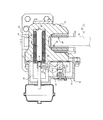
- FIG. 1 is a front view showing an external configuration of a disc brake device according to an embodiment of the present invention.
- FIG. 2 is a diagram showing a cross section along AA in FIG.
- FIG. 3 is a view showing a BB cross section in FIG. 4 is a cross-sectional view taken along the line CC in FIG.
- FIG. 5 is a plan view showing the configuration of the outer piston according to the present embodiment.
- FIG. 1 is a front view showing the appearance of a disc brake device according to an embodiment of the present invention
- FIG. 2 is a view showing a cross section AA in FIG. 3 and 4 are views showing a BB section and a CC section in FIG. 2, respectively.
- FIG. 5 is a plan view showing the configuration of the outer piston of the disc brake device according to the present embodiment.
- the disc brake device 10 is configured based on the caliper body 12, the actuator 58, and the support 62.
- the disc brake device 10 exerts a braking force by pressing a brake pad (piston side pad 38, claw side pad 46) against the sliding surface of the rotor 70.
- the caliper body 12 is configured based on the cylinder portion 14, the claw portion 18, and the back portion 16.
- the cylinder part 14 is formed with a bore 22 as a space for accommodating the cam mechanism 40 together with a cylinder 20 (see FIG. 3) for accommodating the piston 26.
- the cylinder 20 is a hole having an opening with a surface facing the rotor 70 as a tip.
- the bore 22 is a gap formed on the rear end side of the cylinder 20 and extending toward the back portion 16 side.
- a step portion 24 that functions as a reaction force receiver is formed between the cylinder 20 and the bore 22.
- the piston 26 accommodated in the cylinder 20 includes an outer piston 28 and an inner piston 30.
- the outer piston 28 functions as a pressure receiving element and a sliding element.
- the inner piston 30 plays a role as a pressing element and an adjustment element.
- the outer piston 28 and the inner piston 30 are configured as follows.
- the outer piston 28 includes a sliding portion 28a and a pressure receiving portion 28b.
- the sliding portion 28 a includes a sliding surface corresponding to the sliding surface of the cylinder 20 and a recessed portion 28 a 1 that houses the inner piston 30.
- the recessed portion 28a1 has an opening on the side facing the rotor 70 (front end side), and an internal thread is formed on the inner peripheral wall.
- a through hole 28a2 is formed on the bottom surface of the recessed portion 28a1, and a flange portion 28a3 is formed on the rear end side of the sliding portion 28a.
- the through hole 28a2 is an element for inserting an adjuster portion 30b in the inner piston 30 described later in detail.
- the flange portion 28a3 is configured to have a larger diameter than the inner peripheral diameter of the cylinder 20, and when the outer piston 28 is assembled to the cylinder 20, the end surface of the stepped portion 24 and the flange surface of the flange portion 28a3 face each other. It is formed to constitute.
- a reaction force generating mechanism 32 such as a string spring is provided between the end surface of the stepped portion 24 and the flange surface of the flange portion 28a3.
- the pressure receiving portion 28b is connected to the rear end side of the sliding portion 28a and includes a pressure receiving surface 28b1 on the rear end side.
- the pressure receiving surface 28b1 is a contact surface with the cam portion 42a in the cam mechanism 40, which will be described in detail later.
- the pressure receiving surface 28 b 1 is provided with a sliding member 34 such as a half bearing.
- the planar shape thereof is a gate shape as shown in FIG.
- the inner piston 30 includes an inner piston main body 30a and an adjuster portion 30b.
- the inner piston main body 30 a is an element that is accommodated in a recessed portion 28 a 1 formed in the outer piston 28.
- a male screw that is screwed into a female screw formed on the inner peripheral wall of the recessed portion 28a1 is formed.
- the adjuster portion 30b is a rotating shaft connected to the rear end portion of the inner piston 30. By rotating the adjuster portion 30b, the inner piston body 30a also rotates, and the amount of protrusion of the inner piston 30 relative to the outer piston 28 is adjusted. can do.
- a recessed portion 30c for accommodating the square slide pin 36 is formed at the rear end portion of the adjuster portion 30b. By exposing a part of the square sliding pin 36 accommodated in the recessed portion 30 c to the outside of the caliper body 12, the protrusion amount of the inner piston 30 can be adjusted from the outside of the caliper body 12. Further, by making the sliding pin square, there is a hook at the time of applying rotation, and even if the position of the inner piston 30 moves to the rotor 70 side, the position of the square sliding pin 36 is displaced. There is no.
- Brake pads (hereinafter referred to as piston-side pads 38) are arranged on the rotor facing surface side (tip side) of the inner piston 30 in the piston 26 having such a configuration.
- the cam mechanism 40 includes a cam lever 42 and a reaction force receiver 44.
- the cam lever 42 includes a cam portion 42a, a lever portion 42b, and a connecting portion 42c.
- the cam portion 42a is an element that applies a pressing force to the pressure receiving portion 28b of the piston 26 by rotating.
- the lever portion 42b is an element that imparts rotation to the cam portion 42a.
- the connecting portion 42c has a force that contributes to the rotation operation in the braking force generation direction (arrow (A): see FIG. 4) and the braking force release direction (arrow (B): see FIG. 4) with respect to the lever portion 42b.
- the reaction force receiver 44 is an element fixed to the caliper body 12, and in the example according to the present embodiment, constitutes the rotation center of the cam portion 42a.
- a sliding member 34 is preferably provided between the reaction force receiver 44 and the cam portion 42a in the same manner as between the cam portion 42a and the pressure receiving surface 28b1.
- the cam portion 42a configured as shown in FIG.
- the reaction force generation mechanism 32 is provided between the flange portion 28a3 of the outer piston 28 and the step portion 24 between the cylinder 20 and the bore 22, so that the pressing force on the pressure receiving portion 28b is reduced.
- the piston 26 is pulled back in the direction away from the rotor 70.
- the lever portion 42b has a distance (d1) from the rotation center (O) serving as a fulcrum (see FIG. 4) to the outer peripheral surface of the cam portion 42a serving as an action point (a surface facing the pressure receiving surface 28b1 ) .
- connecting portion 42c is sandwiched between a link 56 and a direct acting rod 60, which will be described in detail later, and moves in an arc shape as the cam lever 42 rotates, the contact surface between the link 56 and the direct acting rod 60 In addition, a substantially hemispherical recess is provided.
- the claw portion 18 is an element as a reaction force receiver that is disposed to face the cylinder portion 14 via the rotor 70.
- a brake pad (hereinafter referred to as a claw side pad 46) is disposed on the surface of the claw portion 18 facing the rotor 70.
- the spine portion 16 is an element that connects the cylinder portion 14 and the claw portion 18 across the outer peripheral side of the rotor 70.
- the back portion 16 of the present embodiment is provided with an accommodating portion 48 that accommodates a disc spring 50 as an operating elastic body.
- the accommodating portion 48 is formed as a recessed portion (hole) that forms an opening on the bore 22 side and extends in the axial direction of the rotor 70.
- it is set as the structure which forms the two accommodating parts 48 in parallel with respect to the back part 16. This is to obtain a pressing force necessary to generate a braking force while reducing the diameter of the disc spring 50 accommodated in the accommodating portion 48. With such a configuration, the back portion 16 does not become extremely thick and can contribute to the downsizing of the disc brake device 10.
- Each accommodating portion 48 accommodates a plurality of disc springs 50 and a guide 52 for stacking and holding the disc springs 50.
- the guide 52 is integrally formed with a spring guide 52a for holding the disc spring 50 and a holder guide 52b for guiding a spring holder 54, which will be described in detail later.
- the spring holder 54 is a part of an element for transmitting the axial pressing force (axial force) generated by the disc spring 50 to the connecting portion 42c in the cam mechanism 40, and is divided into two systems. It plays a role to unify the axial force. For this reason, the spring holder 54 is disposed so as to straddle the two holder guides 52b so as to receive the force of both the two disc springs 50.
- the connecting portion 42c of the cam mechanism 40 moves in an arc shape with respect to the axial direction of the rotor 70 as the cam portion 42a rotates.
- the link 56 provided with the hemispherical surface for absorbing the bias
- the actuator 58 is an element for operating the cam mechanism 40 in a direction in which braking is released.
- an air chamber is employed as the actuator 58.
- the air chamber has a linear motion rod 60 that performs linear motion.
- the linearly acting rod 60 as the operating shaft is positioned at the opposing position of the link 56 as the pressing force transmitting portion that transmits the axial force of the disc spring 50 as the operating elastic body.
- An actuator 58 is arranged on the head. Further, as described above, the coupling portion 42c of the cam mechanism 40 is moved in an arc shape with respect to the axial direction of the rotor 70 as the cam portion 42a rotates.
- connection part 42c the front-end
- abutted to the connection part 42c is formed in the hemispherical shape in order to absorb the bias of the contact surface accompanying the rocking
- the cam lever 42 having the connecting portion 42c operates while being sandwiched between the linear motion rod 60 and the link 56.
- the disc spring 50 is configured to transmit a pressing force to the piston 26 via the cam mechanism 40. For this reason, even if the axial force generated by the disc spring 50 itself is small as compared with the conventional case, the pressing force against the piston 26 can be sufficient to obtain a braking force. For this reason, the disk spring 50 can be downsized and the installation space of the disk spring 50 can be reduced. If the actuator 58 generates a pressing force that opposes the axial force of the disc spring 50, the cam mechanism 40 can be operated. Therefore, each element can be reduced in size and weight, and the disc brake device 10 as a whole can be reduced in size and weight.
- the support 62 is an element for holding the caliper body 12 by being fixed to a structure such as an apparatus main body or a vehicle separated from the rotor 70.
- the caliper body 12 is held so as to slide in the axial direction of the rotor 70 via the slide pin 64. Therefore, when the piston 26 protrudes toward the rotor 70 (in the direction of the arrow (C)) and the piston-side pad 38 comes into contact with the rotor 70, the entire caliper body 12 is moved in the direction of the arrow (D) by the reaction force. Slide. As a result, the claw-side pad 46 comes into contact with the rotor 70, and the rotor 70 is clamped by a pair of pads (piston-side pad 38 and claw-side pad 46), so that a braking force is generated.
- the projecting portion of the caliper body 12 is reduced and the size is reduced because the accommodating portion 48 of the disc spring 50 as the operating elastic body is disposed in the back meat portion 16. I can do things. Further, by providing the cam lever 42 between the disc spring 50 accommodated in the back portion 16 and the piston 26 that generates the pressing force, the disc spring 50 itself can be reduced in diameter. It became possible to accommodate in the corresponding part without changing the thickness of 16.
- the disc brake device 10 can be reduced in size, the degree of freedom in designing the device to which the disc brake device 10 is applied can be improved. Further, the present invention can be applied to a site where the installation location is narrow, such as a vehicle. Therefore, it is possible to contribute to the expansion of the range to which the negative type disc brake device 10 is applied.
- an air chamber is employed as the actuator 58.
- a motor gear unit may be adopted as the actuator 58. This is because even with such a configuration, the effects of the present invention can be achieved. Further, with such a configuration, piping for operation becomes unnecessary, and the degree of freedom when installing the disc brake device 10 can be improved.
- the disc springs 50 as the operating elastic bodies are arranged in two systems, the diameter thereof can be suppressed, and a sufficient axial force can be generated.
- the disc spring 50 may be a single system. Naturally, the number of disc springs 50 may be further increased.
- the axial force generation direction (arrangement axis direction) of the disc spring 50 and the protruding direction of the piston 26 (arrow (C)) are described in parallel.
- the cam mechanism 40 is provided between the disc spring 50 and the piston 26, the force is transmitted even when the two axes are deviated from the parallel relationship. Therefore, the arrangement axis direction of the disc spring 50 and the protruding direction of the piston 26 may have an angle.
- the link 56 and the linearly acting rod 60 are arranged at the opposed positions via the connecting portion 42c of the cam lever 42.
- the arrangement positions of both may not necessarily be the opposed positions. That is, even when the lever part 42b is displaced in the arrangement direction, the same effect can be obtained only by the difference in the force required for the action.
- the accommodating portion 48 in which the disc spring 50 is disposed has been described as a recessed portion having an opening on the bore 22 side.
- the accommodating portion 48 may be an open back type having an opening in the radial direction of the rotor 70. good.
- disc brake device of the present invention is not limited to the above-described embodiment, and appropriate modifications and improvements can be made based on the gist of the present invention.
- This application is based on a Japanese patent application (Japanese Patent Application No. 2017-90734) filed on April 28, 2017, the contents of which are incorporated herein by reference.
- a disc brake device (10) comprising a transmission mechanism (cam mechanism 40) for transmitting a pressing force of the operating elastic body (belleville spring 50) to the piston (26).
- An actuator (58) is provided at a position along an axis that generates a pressing force of the operating elastic body (belleville spring 50) and has an operating shaft (linear motion rod 60) that generates a reaction force against the pressing force.
- a disc brake device (10) provided with a pressing force transmission part (link 56) via a holder (spring holder 54) that is provided at a position facing the operating shaft (linear motion rod 60) and transmits the pressing force.
- a disc brake device according to any one of [2] to [3] above, A disc brake device (10) in which the actuator (58) is an air chamber.
- a disc brake device according to any one of [2] to [3], A disc brake device (10) in which the actuator (58) is a motor gear unit.
- the negative type disc brake device can be made smaller and lighter than before. Further, due to the reduction in size and weight, it is possible to increase the degree of freedom in designing the device to be attached and the range of application.
Landscapes
- Engineering & Computer Science (AREA)
- General Engineering & Computer Science (AREA)
- Mechanical Engineering (AREA)
- Braking Arrangements (AREA)
Abstract
キャリパボディ(12)のシリンダ(20)内に配置されたピストン(26)が、皿ばね(50)からの押圧力を受けることにより、ピストン側パッド(38)を押圧するディスクブレーキ装置(10)であって、皿ばね(50)は、少なくとも一部がキャリパボディ(12)に内包されると共に、ピストン(26)の突出方向と異なる方向に押圧力を生じさせる軸を持つように配置され、皿ばね(50)の押圧力をピストン(26)に伝達するカム機構(40)を備えている。
Description
本発明は、ディスクブレーキ装置に係り、特に、非稼働時に制動力を生じさせる、いわゆるネガティブタイプのディスクブレーキ装置に関する。
産業機械などで、回転体の保持にディスクブレーキ装置が用いられる際、皿ばねの荷重を直接制動力に用いるネガティブタイプのディスクブレーキ装置が採用されることが多い。このような構造のディスクブレーキ装置では、制動力の解除に油圧の力を利用するものが一般的に知られているが、油圧機構を採用するためのスペースや配管を排除し、小型で簡易なシステムとする事が望まれていた。
このような実状に鑑み、本願出願人は、特許文献1に開示されているような、制動力の解除機構にカム機構を採用したディスクブレーキ装置を提案している。特許文献1に開示されているディスクブレーキ装置は、キャリパボディの一部を支持部としてカムを回動させる事で、皿ばねによって押圧されているピストンをロータから離間する側へ押圧するという機構を備えるものである。カムは、キャリパボディの背肉部を貫通するロッドを動作させるアクチュエータに接続されたレバー部を備え、梃子の原理により、小さな力によっても大きな皿ばねの荷重に対する反力を生じさせることが可能な構成とされている。
上記特許文献1に開示されているディスクブレーキ装置によれば、制動の解除に大きな力を必要としないため、アクチュエータとして、エアや電力により動作するものを採用する事ができる。また、制動解除機構に油圧機構を採用するディスクブレーキ装置に比べ、小型化を図ることも可能となる。
しかし、産業機械等において、装置全体の小型化が図られたり、多機能化が求められる中では、ディスクブレーキ装置をさらに小型化し、装置設計の自由度を向上させたり、適用する機械自体に幅を持たせる事が望まれてきている。
そこで本発明では、ネガティブタイプのディスクブレーキ装置において、従来よりも小型化を図り、装置設計の自由度、並びに適用範囲の拡大に寄与する事のできるディスクブレーキ装置を提供することを目的とする。
本発明に係る上記目的は、下記構成のディスクブレーキ装置により達成される。
(1) キャリパボディのシリンダ内に配置されたピストンが、作動弾性体からの押圧力を受けることにより、ブレーキパッドを押圧するディスクブレーキ装置であって、前記作動弾性体は、少なくとも一部が前記キャリパボディに内包されると共に、前記ピストンの突出方向と異なる方向に押圧力を生じさせる軸を持つように配置され、前記作動弾性体の押圧力を前記ピストンに伝達する伝達機構を備えているディスクブレーキ装置。
(1) キャリパボディのシリンダ内に配置されたピストンが、作動弾性体からの押圧力を受けることにより、ブレーキパッドを押圧するディスクブレーキ装置であって、前記作動弾性体は、少なくとも一部が前記キャリパボディに内包されると共に、前記ピストンの突出方向と異なる方向に押圧力を生じさせる軸を持つように配置され、前記作動弾性体の押圧力を前記ピストンに伝達する伝達機構を備えているディスクブレーキ装置。
(2) 上記(1)の構成を有するディスクブレーキ装置であって、前記作動弾性体の押圧力を生じさせる軸に沿った位置に設けられ、前記押圧力に対する反力を生じさせる作動軸を有するアクチュエータを備えたディスクブレーキ装置。
このような構成を有する事により、制動力を解除する事が可能となる。
このような構成を有する事により、制動力を解除する事が可能となる。
(3) 上記(2)の構成を有するディスクブレーキ装置であって、前記作動軸の対向位置に設けられ、前記押圧力を伝達するホルダを介した押圧力伝達部を備えたディスクブレーキ装置。
このような構成を有する事により、作動弾性体が複数存在する場合であっても、押圧力を伝達機構に伝達する力伝達経路を1系統にまとめることができる。
このような構成を有する事により、作動弾性体が複数存在する場合であっても、押圧力を伝達機構に伝達する力伝達経路を1系統にまとめることができる。
(4) 上記(2)~(3)のいずれか1つの構成を有するディスクブレーキ装置であって、前記アクチュエータがエアチャンバであるディスクブレーキ装置。
このような構成を有する事によれば、作動油を必要としないため、装置全体の小型化を図る事ができる。
このような構成を有する事によれば、作動油を必要としないため、装置全体の小型化を図る事ができる。
(5) 上記(2)~(3)のいずれか1つの構成を有するディスクブレーキ装置であって、前記アクチュエータがモータギヤユニットであるディスクブレーキ装置。
このような構成を有する事によれば、作動動作に必要な配管が不要となる。よって、装置設置の自由度を向上させることができる。
このような構成を有する事によれば、作動動作に必要な配管が不要となる。よって、装置設置の自由度を向上させることができる。
(6) 上記(1)~(5)のいずれか1つの構成を有するディスクブレーキ装置であって、
前記キャリパボディの背肉部に、前記作動弾性体を配置したディスクブレーキ装置。
このような構成を有する事により、キャリパボディの外部に突出する部位を減らす事ができる。よって、ディスクブレーキ装置の小型化を図る事ができる。
前記キャリパボディの背肉部に、前記作動弾性体を配置したディスクブレーキ装置。
このような構成を有する事により、キャリパボディの外部に突出する部位を減らす事ができる。よって、ディスクブレーキ装置の小型化を図る事ができる。
(7) 上記(6)の構成を有するディスクブレーキ装置であって、前記背肉部に、前記作動弾性体が2つ以上備えられているディスクブレーキ装置。
このような構成を有する事により、少なくとも押圧力を増やす事が可能となる。また、作動弾性体の数を増やす事によれば、個々の作動弾性体を縮小化する事ができる。このため、分散配置が可能となり、大きな配置スペースを不要とする事ができる。よって、ディスクブレーキ装置の小型化に寄与する事ができる。
このような構成を有する事により、少なくとも押圧力を増やす事が可能となる。また、作動弾性体の数を増やす事によれば、個々の作動弾性体を縮小化する事ができる。このため、分散配置が可能となり、大きな配置スペースを不要とする事ができる。よって、ディスクブレーキ装置の小型化に寄与する事ができる。
上記のような構成を有することによれば、ネガティブタイプのディスクブレーキ装置において、従来よりも小型、軽量化を図ることができる。また、小型、軽量化に起因して、取り付け対象とする装置設計の自由度、並びに適用範囲の拡大を図る事が可能となる。
以下、本発明のディスクブレーキ装置について、図面を参照しつつ詳細に説明する。なお、図面において、図1は、本発明の一実施形態に係るディスクブレーキ装置の外観を現した正面図であり、図2は、図1におけるA-A断面を表す図である。また、図3と図4は、それぞれ図2におけるB-B断面とC-C断面を表す図である。さらに、図5は、本実施形態に係るディスクブレーキ装置のアウタピストンの構成を示す平面図である。
本実施形態に係るディスクブレーキ装置10は、キャリパボディ12と、アクチュエータ58、及びサポート62を基本として構成されている。ディスクブレーキ装置10は、ロータ70の摺動面にブレーキパッド(ピストン側パッド38、爪側パッド46)を押し付けることで、制動力を発揮する。
キャリパボディ12は、シリンダ部14と爪部18、および背肉部16を基本として構成されている。シリンダ部14は、ピストン26を収容するシリンダ20(図3参照)と共に、カム機構40を収容する空間としてのボア22が形成されている。シリンダ20は、ロータ70との対向面を先端として開口を有する穴である。ボア22は、シリンダ20の後端側に形成され、背肉部16側へと延接されている空隙である。本実施形態に係るキャリパボディ12では、シリンダ20とボア22との間に、反力受けとしての作用を奏する段差部24が形成されている。
シリンダ20に収容されるピストン26は、アウタピストン28とインナピストン30により構成されている。アウタピストン28は、受圧要素、及び摺動要素としての作用を担う。インナピストン30は、押圧要素、及び調整要素としての役割を担う。本実施形態では、アウタピストン28とインナピストン30について、それぞれ次のような構成としている。
アウタピストン28は、摺動部28aと受圧部28bにより構成されている。摺動部28aは、シリンダ20の摺動面に対応する摺動面と、インナピストン30を収容する凹陥部28a1とを備える。凹陥部28a1は、ロータ70との対向面側(先端側)に開口部を有し、内周壁には雌ネジが形成されている。また、凹陥部28a1の底面には、貫通孔28a2が形成されていると共に、摺動部28aの後端側には、フランジ部28a3が形成されている。貫通孔28a2は、詳細を後述するインナピストン30におけるアジャスタ部30bを挿通させるための要素である。また、フランジ部28a3は、シリンダ20の内周径よりも大径となるように構成され、アウタピストン28をシリンダ20に組み付けた際、段差部24の端面とフランジ部28a3のフランジ面が対向面を構成するように形成されている。そして、段差部24の端面とフランジ部28a3のフランジ面との間には、弦巻バネ等の反力発生機構32が設けられている。
受圧部28bは、摺動部28aの後端側に連接されており、後端側に受圧面28b1を備える。受圧面28b1は、詳細を後述するカム機構40におけるカム部42aとの接触面である。受圧面28b1は、図3、図4に示す形態では、半割軸受等の摺動部材34が設けられている。ここで、受圧部28bは、貫通孔28a2に挿通されるアジャスタ部30bを避けるように分割して配置されるため、その平面形態は、図5に示すように門型となる。
インナピストン30は、インナピストン本体30aと、アジャスタ部30bとにより構成されている。インナピストン本体30aは、アウタピストン28に形成された凹陥部28a1に収容される要素である。インナピストン本体30aの外周面には、凹陥部28a1の内周壁に形成されている雌ネジに螺合する雄ネジが形成されている。
アジャスタ部30bは、インナピストン30の後端部に連接される回転軸であり、アジャスタ部30bを回転させる事で、インナピストン本体30aも回転し、アウタピストン28に対するインナピストン30の突出量を調整することができる。アジャスタ部30bの後端部には、角型摺動ピン36を収容するための凹陥部30cが形成されている。凹陥部30cに収容される角型摺動ピン36の一部をキャリパボディ12の外部に晒す事で、キャリパボディ12の外部から、インナピストン30の突出量の調整が可能となる。また、摺動ピンを角型とする事で、回転付与時の掛かりを奏すると共に、インナピストン30の位置がロータ70側へ移動したとしても、角型摺動ピン36の位置に変位が生じる事が無い。
このような構成のピストン26におけるインナピストン30のロータ対向面側(先端側)には、ブレーキパッド(以下、ピストン側パッド38と称す)が配置されている。
カム機構40は、カムレバー42と反力受け44とから構成される。カムレバー42は、カム部42aと、レバー部42b、及び連結部42cを有する。カム部42aは、回動によりピストン26の受圧部28bに対して押圧力を付与する要素である。レバー部42bは、カム部42aに回転を付与する要素である。また、連結部42cは、レバー部42bに対して、制動力発生方向(矢印(A):図4参照)の回転動作に寄与する力と、制動力解除方向(矢印(B):図4参照)の回転動作に寄与する力を与えるための各要素(詳細を後述するリンク56と直動ロッド60)の力をレバー部42bに伝えるための要素である。
反力受け44は、キャリパボディ12に固定された要素であり、本実施形態に係る例では、カム部42aの回転中心を構成する。反力受け44とカム部42aとの間には、カム部42aと受圧面28b1との間と同様に、摺動部材34が設けられると良い。
図3、図4に示す構成のカム部42aは、矢印(A)の方向に回動する事で、ピストン26をロータ70の配置方向へ押圧する。一方、矢印(B)の方向に回動した場合には、受圧部28bに対する押圧力が解除される。本実施形態の場合、アウタピストン28におけるフランジ部28a3と、シリンダ20とボア22の間の段差部24との間に反力発生機構32が設けられていることにより、受圧部28bに対する押圧力が解除される事で、ピストン26がロータ70から離間する方向へ引き戻される。
また、レバー部42bは、支点となる回転中心(O)(図4参照)から、作用点となるカム部42aの外周面(受圧面28b1との対向面)までの距離(d1)と、回転中心(O)から力点となる連結部42cまでの距離(d2)との差を大きくとる事で、梃子の原理により、小さな力で大きな回転トルク(ロータ70の軸線方向(P)に変換されると押圧力)を生じさせることが可能となる。
連結部42cは、詳細を後述するリンク56と直動ロッド60に挟持されると共に、カムレバー42の回動に伴い、円弧状に移動する事から、リンク56、および直動ロッド60との接触面に、ほぼ半球状の凹陥部を設けている。
爪部18は、ロータ70を介してシリンダ部14と対向配置される反力受けとしての要素である。爪部18におけるロータ70との対向面側には、ブレーキパッド(以下、爪側パッド46と称す)が配置されている。
背肉部16は、ロータ70の外周側を跨いで、シリンダ部14と爪部18とを連結する要素である。本実施形態の背肉部16には、作動弾性体としての皿ばね50を収容する収容部48が設けられている。収容部48は、ボア22側に開口部を形成し、ロータ70の軸方向に延設された凹陥部(穴)として形成されている。本実施形態の場合、背肉部16に対して並列に、2つの収容部48を形成する構成とされている。収容部48に収容する皿ばね50の直径を小さくしつつ、制動力を生じさせるのに必要な押圧力を得るためである。このような構成とする事で、背肉部16を極端に厚肉化する事がなく、ディスクブレーキ装置10の小型化に寄与する事ができる。
各収容部48には、複数の皿ばね50と、この皿ばね50を積層保持するためのガイド52が収容されている。なお、本実施形態の場合、ガイド52は、皿ばね50を保持するためのスプリングガイド52aと、詳細を後述するスプリングホルダ54をガイドするためのホルダガイド52bとが一体に形成されている。
スプリングホルダ54は、皿ばね50によって発生する軸線方向の押圧力(軸力)をカム機構40における連結部42cに伝達するための要素の一部であり、2系統に分割されている皿ばね50からの軸力を統一化する役割を担う。このため、スプリングホルダ54は、2系統の皿ばね50双方の力を受けるように、2つのホルダガイド52bを跨ぐように配置される。
ここで、カム機構40の連結部42cは、カム部42aの回転に伴い、ロータ70の軸線方向に対して円弧状の動きが成される。このため、スプリングホルダ54と連結部42cの間には、連結部42cの揺動に伴う接触面の偏りを吸収するための半球面を備えたリンク56が設けられている。
アクチュエータ58は、本実施形態の場合、制動を解除させる方向にカム機構40を動作させるための要素である。本実施形態では、アクチュエータ58として、エアチャンバを採用している。エアチャンバは、直線運動を成す直動ロッド60を有する。本実施形態に係るディスクブレーキ装置10では、作動弾性体としての皿ばね50の軸力を伝達する押圧力伝達部としてのリンク56の対向位置に、作動軸としての直動ロッド60が位置するようにアクチュエータ58を配置している。また、上述したように、カム機構40の連結部42cは、カム部42aの回転に伴い、ロータ70の軸線方向に対して円弧状の動きが成される。このため、連結部42cに当接する直動ロッド60の先端部は、連結部42cの揺動に伴う接触面の偏りを吸収するために、半球状に形成されている。
このような配置形態のディスクブレーキ装置10では、連結部42cを有するカムレバー42が、直動ロッド60とリンク56とに挟持された状態で動作することとなる。また、皿ばね50は、カム機構40を介してピストン26に押圧力を伝達する構成とされている。このため、従来に比べ、皿ばね50自体により生じさせる軸力が小さなものであっても、ピストン26に対する押圧力は、制動力を得るのに充分な力とすることができる。このため、皿ばね50の小型化、並びに皿ばね50の設置スペースの狭小化を図ることができる。また、アクチュエータ58は、皿ばね50の軸力に対向する押圧力を生じさせるものであれば、カム機構40を動作させる事が可能となる。よって、各要素の小型、軽量化を図る事ができ、ディスクブレーキ装置10全体としても、小型、軽量化を図る事ができる。
サポート62は、ロータ70と離間した装置本体や車両等の構造物に固定され、キャリパボディ12を保持するための要素である。本実施形態に係るディスクブレーキ装置10では、摺動ピン64を介してロータ70の軸線方向にキャリパボディ12が摺動するように保持されている。このため、ピストン26がロータ70側(矢印(C)の方向)へ突出することでピストン側パッド38がロータ70に当接すると、その反力によりキャリパボディ12全体が矢印(D)の方向へ摺動する。これにより爪側パッド46がロータ70に当接し、対を成すパッド(ピストン側パッド38と爪側パッド46)によりロータ70が挟持され、制動力が生ずることとなる。
このような構成のディスクブレーキ装置10によれば、作動弾性体としての皿ばね50の収容部48を背肉部16に配置したことより、キャリパボディ12の突出部が減少し、小型化を図る事ができる。また、背肉部16に収容した皿ばね50と押圧力を生じさせるピストン26との間にカムレバー42を備えた事により、皿ばね50自体の小径化を図る事ができ、従来の背肉部16の厚さを変える事なく、該当部位に収容する事が可能となった。
このように、ディスクブレーキ装置10の小型化を図る事ができた事により、ディスクブレーキ装置10を適用する装置設計の自由度を向上させることができる。また、車両などのように、設置場所が狭隘な部位にも適用することが可能となる。よって、ネガティブタイプのディスクブレーキ装置10を適用する範囲の拡大に寄与することもできる。
また、上記実施形態では、アクチュエータ58としてエアチャンバを採用する旨記載した。しかしながら、従来技術と同様に、アクチュエータ58として、モータギヤユニットを採用しても良い。このような構成とした場合であっても、本発明の効果を奏する事ができるからである。また、このような構成とする事で、作動のための配管が不要となり、ディスクブレーキ装置10を設置する際の自由度を向上させることができる。
また、上記実施形態では、作動弾性体としての皿ばね50について、2系統に配置し、その直径を抑え、かつ十分な軸力を生じさせることが可能な構成とした旨記載した。しかしながら、皿ばね50の材質や形態によって、十分な軸力を生じさせることができれば、皿ばね50を1系統としても良い。また当然に、皿ばね50の系統数をさらに増やしても良い。
また、上記実施形態では、皿ばね50の軸力発生方向(配置軸方向)と、ピストン26の突出方向(矢印(C))とが平行であるように記載している。しかしながら、皿ばね50とピストン26との間にはカム機構40が備えられていることにより、力の伝達は、2つの軸が平行関係からズレた場合であっても成されることとなる。よって、皿ばね50の配置軸方向と、ピストン26の突出方向とが角度を持つ構成としても良い。
また、上記実施形態では、リンク56と直動ロッド60とは、カムレバー42の連結部42cを介して対向位置に配置されていたが、両者の配置位置は、必ずしも対向位置としなくても良い。すなわち、レバー部42bの配置方向にズレている場合でも、作用に必要とされる力が異なるだけで、同様な効果を得る事ができる。
また、上記実施形態では、皿ばね50を配置する収容部48について、ボア22側に開口部を持つ凹陥部であると説明した。しかしながら、収容部48は、少なくとも皿ばね50の一部を内包し、かつ背肉部16として、必要十分な強度を備える構成であれば、ロータ70の半径方向に開口を備えるオープンバック型としても良い。
なお、本発明のディスクブレーキ装置は、上述した実施形態に限定されるものでなく、本発明の趣旨に基づいて適宜な変形、改良等が可能である。
また、本出願は、2017年4月28日出願の日本特許出願(特願2017-90734)に基づくものであり、その内容はここに参照として取り込まれる。
また、本出願は、2017年4月28日出願の日本特許出願(特願2017-90734)に基づくものであり、その内容はここに参照として取り込まれる。
ここで、上述した本発明に係るディスクブレーキ装置の実施形態の特徴をそれぞれ以下に簡潔に纏めて列記する。
[1] キャリパボディ(12)のシリンダ(20)内に配置されたピストン(26)が、作動弾性体(皿ばね50)からの押圧力(軸力)を受けることにより、ブレーキパッド(ピストン側パッド38、爪側パッド46)を押圧するディスクブレーキ装置であって、
前記作動弾性体(皿ばね50)は、少なくとも一部が前記キャリパボディ(12)に内包されると共に、前記ピストン(26)の突出方向と異なる方向(配置軸方向)に押圧力(軸力)を生じさせる軸を持つように配置され、
前記作動弾性体(皿ばね50)の押圧力を前記ピストン(26)に伝達する伝達機構(カム機構40)を備えているディスクブレーキ装置(10)。
[2] 上記[1]に記載のディスクブレーキ装置であって、
前記作動弾性体(皿ばね50)の押圧力を生じさせる軸に沿った位置に設けられ、前記押圧力に対する反力を生じさせる作動軸(直動ロッド60)を有するアクチュエータ(58)を備えたディスクブレーキ装置(10)。
[3] 上記[2]に記載のディスクブレーキ装置であって、
前記作動軸(直動ロッド60)の対向位置に設けられ、前記押圧力を伝達するホルダ(スプリングホルダ54)を介した押圧力伝達部(リンク56)を備えたディスクブレーキ装置(10)。
[4] 上記[2]~[3]のいずれか1つに記載のディスクブレーキ装置であって、
前記アクチュエータ(58)がエアチャンバであるディスクブレーキ装置(10)。
[5] 上記[2]~[3]のいずれか1つに記載のディスクブレーキ装置であって、
前記アクチュエータ(58)がモータギヤユニットであるディスクブレーキ装置(10)。
[6] 上記[1]~[5]のいずれか1つに記載のディスクブレーキ装置であって、
前記キャリパボディ(12)の背肉部(16)に、前記作動弾性体(皿ばね50)を配置したディスクブレーキ装置(10)。
[7] 上記[6]に記載のディスクブレーキ装置であって、
前記背肉部(16)に、前記作動弾性体(皿ばね50)が2つ以上備えられているディスクブレーキ装置(10)。
[1] キャリパボディ(12)のシリンダ(20)内に配置されたピストン(26)が、作動弾性体(皿ばね50)からの押圧力(軸力)を受けることにより、ブレーキパッド(ピストン側パッド38、爪側パッド46)を押圧するディスクブレーキ装置であって、
前記作動弾性体(皿ばね50)は、少なくとも一部が前記キャリパボディ(12)に内包されると共に、前記ピストン(26)の突出方向と異なる方向(配置軸方向)に押圧力(軸力)を生じさせる軸を持つように配置され、
前記作動弾性体(皿ばね50)の押圧力を前記ピストン(26)に伝達する伝達機構(カム機構40)を備えているディスクブレーキ装置(10)。
[2] 上記[1]に記載のディスクブレーキ装置であって、
前記作動弾性体(皿ばね50)の押圧力を生じさせる軸に沿った位置に設けられ、前記押圧力に対する反力を生じさせる作動軸(直動ロッド60)を有するアクチュエータ(58)を備えたディスクブレーキ装置(10)。
[3] 上記[2]に記載のディスクブレーキ装置であって、
前記作動軸(直動ロッド60)の対向位置に設けられ、前記押圧力を伝達するホルダ(スプリングホルダ54)を介した押圧力伝達部(リンク56)を備えたディスクブレーキ装置(10)。
[4] 上記[2]~[3]のいずれか1つに記載のディスクブレーキ装置であって、
前記アクチュエータ(58)がエアチャンバであるディスクブレーキ装置(10)。
[5] 上記[2]~[3]のいずれか1つに記載のディスクブレーキ装置であって、
前記アクチュエータ(58)がモータギヤユニットであるディスクブレーキ装置(10)。
[6] 上記[1]~[5]のいずれか1つに記載のディスクブレーキ装置であって、
前記キャリパボディ(12)の背肉部(16)に、前記作動弾性体(皿ばね50)を配置したディスクブレーキ装置(10)。
[7] 上記[6]に記載のディスクブレーキ装置であって、
前記背肉部(16)に、前記作動弾性体(皿ばね50)が2つ以上備えられているディスクブレーキ装置(10)。
本発明のディスクブレーキ装置によれば、ネガティブタイプのディスクブレーキ装置において、従来よりも小型、軽量化を図ることができる。また、小型、軽量化に起因して、取り付け対象とする装置設計の自由度、並びに適用範囲の拡大を図る事が可能となる。
10………ディスクブレーキ装置、12………キャリパボディ、14………シリンダ部、16………背肉部、18………爪部、20………シリンダ、22………ボア、24………段差部、26………ピストン、28………アウタピストン、28a………摺動部、28a1………凹陥部、28a2………貫通孔、28a3………フランジ部、28b………受圧部、28b1………受圧面、30………インナピストン、30a………インナピストン本体、30b………アジャスタ部、30c………凹陥部、32………反力発生機構、34………摺動部材、36………角型摺動ピン、38………ピストン側パッド(ブレーキパッド)、40………カム機構(伝達機構)、42………カムレバー、42a………カム部、42b………レバー部、42c………連結部、44………反力受け、46………爪側パッド(ブレーキパッド)、48………収容部、50………皿ばね(作動弾性体)、52………ガイド、52a………スプリングガイド、52b………ホルダガイド、54………スプリングホルダ、56………リンク(押圧力伝達部)、58………アクチュエータ、60………直動ロッド(作動軸)、62………サポート、64………摺動ピン、70………ロータ。
Claims (7)
- キャリパボディのシリンダ内に配置されたピストンが、作動弾性体からの押圧力を受けることにより、ブレーキパッドを押圧するディスクブレーキ装置であって、
前記作動弾性体は、少なくとも一部が前記キャリパボディに内包されると共に、前記ピストンの突出方向と異なる方向に押圧力を生じさせる軸を持つように配置され、
前記作動弾性体の押圧力を前記ピストンに伝達する伝達機構を備えているディスクブレーキ装置。 - 請求項1に記載のディスクブレーキ装置であって、
前記作動弾性体の押圧力を生じさせる軸に沿った位置に設けられ、前記押圧力に対する反力を生じさせる作動軸を有するアクチュエータを備えたディスクブレーキ装置。 - 請求項2に記載のディスクブレーキ装置であって、
前記作動軸の対向位置に設けられ、前記押圧力を伝達するホルダを介した押圧力伝達部を備えたディスクブレーキ装置。 - 請求項2~3のいずれか1項に記載のディスクブレーキ装置であって、
前記アクチュエータがエアチャンバであるディスクブレーキ装置。 - 請求項2~3のいずれか1項に記載のディスクブレーキ装置であって、
前記アクチュエータがモータギヤユニットであるディスクブレーキ装置。 - 請求項1~5のいずれか1項に記載のディスクブレーキ装置であって、
前記キャリパボディの背肉部に、前記作動弾性体を配置したディスクブレーキ装置。 - 請求項6に記載のディスクブレーキ装置であって、
前記背肉部に、前記作動弾性体が2つ以上備えられているディスクブレーキ装置。
Applications Claiming Priority (2)
| Application Number | Priority Date | Filing Date | Title |
|---|---|---|---|
| JP2017090734A JP2018189130A (ja) | 2017-04-28 | 2017-04-28 | ディスクブレーキ装置 |
| JP2017-090734 | 2017-04-28 |
Publications (1)
| Publication Number | Publication Date |
|---|---|
| WO2018199114A1 true WO2018199114A1 (ja) | 2018-11-01 |
Family
ID=63919767
Family Applications (1)
| Application Number | Title | Priority Date | Filing Date |
|---|---|---|---|
| PCT/JP2018/016677 Ceased WO2018199114A1 (ja) | 2017-04-28 | 2018-04-24 | ディスクブレーキ装置 |
Country Status (2)
| Country | Link |
|---|---|
| JP (1) | JP2018189130A (ja) |
| WO (1) | WO2018199114A1 (ja) |
Cited By (2)
| Publication number | Priority date | Publication date | Assignee | Title |
|---|---|---|---|---|
| WO2020189356A1 (ja) * | 2019-03-19 | 2020-09-24 | 日信工業株式会社 | 車両用ディスクブレーキのキャリパボディ |
| CN114651139A (zh) * | 2019-10-22 | 2022-06-21 | 索尤若驱动有限及两合公司 | 制动装置和具有制动装置的电机 |
Citations (5)
| Publication number | Priority date | Publication date | Assignee | Title |
|---|---|---|---|---|
| JPS60205035A (ja) * | 1984-02-29 | 1985-10-16 | ソシエテ・アノニム・デ−・ベ−・ア− | デイスクブレ−キ用駆動装置 |
| JPH0344542U (ja) * | 1989-09-04 | 1991-04-25 | ||
| JP2004060862A (ja) * | 2002-07-31 | 2004-02-26 | Nabco Ltd | バネブレーキシリンダ及びそれを備えたブレーキキャリパ装置 |
| WO2015173884A1 (ja) * | 2014-05-13 | 2015-11-19 | 三菱電機株式会社 | エレベータ用巻上機のブレーキ装置 |
| JP2016166669A (ja) * | 2014-12-16 | 2016-09-15 | 曙ブレーキ工業株式会社 | ディスクブレーキ装置 |
-
2017
- 2017-04-28 JP JP2017090734A patent/JP2018189130A/ja active Pending
-
2018
- 2018-04-24 WO PCT/JP2018/016677 patent/WO2018199114A1/ja not_active Ceased
Patent Citations (5)
| Publication number | Priority date | Publication date | Assignee | Title |
|---|---|---|---|---|
| JPS60205035A (ja) * | 1984-02-29 | 1985-10-16 | ソシエテ・アノニム・デ−・ベ−・ア− | デイスクブレ−キ用駆動装置 |
| JPH0344542U (ja) * | 1989-09-04 | 1991-04-25 | ||
| JP2004060862A (ja) * | 2002-07-31 | 2004-02-26 | Nabco Ltd | バネブレーキシリンダ及びそれを備えたブレーキキャリパ装置 |
| WO2015173884A1 (ja) * | 2014-05-13 | 2015-11-19 | 三菱電機株式会社 | エレベータ用巻上機のブレーキ装置 |
| JP2016166669A (ja) * | 2014-12-16 | 2016-09-15 | 曙ブレーキ工業株式会社 | ディスクブレーキ装置 |
Cited By (4)
| Publication number | Priority date | Publication date | Assignee | Title |
|---|---|---|---|---|
| WO2020189356A1 (ja) * | 2019-03-19 | 2020-09-24 | 日信工業株式会社 | 車両用ディスクブレーキのキャリパボディ |
| CN113614407A (zh) * | 2019-03-19 | 2021-11-05 | 日立安斯泰莫株式会社 | 车辆用盘式制动器的制动钳主体 |
| JP7541506B2 (ja) | 2019-03-19 | 2024-08-28 | 日立Astemo株式会社 | 車両用ディスクブレーキのキャリパボディ |
| CN114651139A (zh) * | 2019-10-22 | 2022-06-21 | 索尤若驱动有限及两合公司 | 制动装置和具有制动装置的电机 |
Also Published As
| Publication number | Publication date |
|---|---|
| JP2018189130A (ja) | 2018-11-29 |
Similar Documents
| Publication | Publication Date | Title |
|---|---|---|
| JP5073683B2 (ja) | クランプおよび/またはブレーキ機構 | |
| EP1847430A1 (en) | Hydraulic modulator for brake device | |
| JP4878363B2 (ja) | 車輪ブレーキ | |
| WO2016098819A1 (ja) | ディスクブレーキ装置 | |
| CN107407361A (zh) | 制动装置 | |
| CN108026994A (zh) | 制动装置 | |
| US11788589B2 (en) | Drum brake apparatus | |
| WO2014189089A1 (ja) | ディスクブレーキ装置 | |
| JP2017154541A (ja) | 反力発生装置およびブレーキ装置 | |
| JP6277514B2 (ja) | ディスクブレーキ装置 | |
| WO2018199114A1 (ja) | ディスクブレーキ装置 | |
| JP2019116965A (ja) | ブレーキ装置 | |
| WO2015098782A1 (ja) | ディスクブレーキ装置 | |
| EP3650725A1 (en) | Disc brake device | |
| CN113719563B (zh) | 制动装置和制动装置用的间隙调整机构 | |
| JP6288580B2 (ja) | ディスクブレーキ装置 | |
| JP2008151167A (ja) | ディスクブレーキ装置 | |
| JP7102867B2 (ja) | 回転直動変換装置及び車両用ブレーキ | |
| JP2009537768A (ja) | クラッチ調節装置及びその制御方法 | |
| JP2021124148A (ja) | クラッチ装置 | |
| WO2016175107A1 (ja) | ディスクブレーキ装置 | |
| JP5057174B2 (ja) | ディスクブレーキ | |
| TW202130549A (zh) | 連動煞車系統 | |
| JP6803953B2 (ja) | ディスクブレーキ装置 | |
| KR102364422B1 (ko) | 클러치 작동기구용 댐핑장치 |
Legal Events
| Date | Code | Title | Description |
|---|---|---|---|
| 121 | Ep: the epo has been informed by wipo that ep was designated in this application |
Ref document number: 18790534 Country of ref document: EP Kind code of ref document: A1 |
|
| NENP | Non-entry into the national phase |
Ref country code: DE |
|
| 122 | Ep: pct application non-entry in european phase |
Ref document number: 18790534 Country of ref document: EP Kind code of ref document: A1 |