WO2018198554A1 - エンジンシステム - Google Patents
エンジンシステム Download PDFInfo
- Publication number
- WO2018198554A1 WO2018198554A1 PCT/JP2018/009619 JP2018009619W WO2018198554A1 WO 2018198554 A1 WO2018198554 A1 WO 2018198554A1 JP 2018009619 W JP2018009619 W JP 2018009619W WO 2018198554 A1 WO2018198554 A1 WO 2018198554A1
- Authority
- WO
- WIPO (PCT)
- Prior art keywords
- engine
- cooling water
- reducing agent
- unit
- heat exchange
- Prior art date
- Legal status (The legal status is an assumption and is not a legal conclusion. Google has not performed a legal analysis and makes no representation as to the accuracy of the status listed.)
- Ceased
Links
Images

Classifications
-
- F—MECHANICAL ENGINEERING; LIGHTING; HEATING; WEAPONS; BLASTING
- F01—MACHINES OR ENGINES IN GENERAL; ENGINE PLANTS IN GENERAL; STEAM ENGINES
- F01N—GAS-FLOW SILENCERS OR EXHAUST APPARATUS FOR MACHINES OR ENGINES IN GENERAL; GAS-FLOW SILENCERS OR EXHAUST APPARATUS FOR INTERNAL-COMBUSTION ENGINES
- F01N3/00—Exhaust or silencing apparatus having means for purifying, rendering innocuous, or otherwise treating exhaust
- F01N3/08—Exhaust or silencing apparatus having means for purifying, rendering innocuous, or otherwise treating exhaust for rendering innocuous
-
- F—MECHANICAL ENGINEERING; LIGHTING; HEATING; WEAPONS; BLASTING
- F01—MACHINES OR ENGINES IN GENERAL; ENGINE PLANTS IN GENERAL; STEAM ENGINES
- F01P—COOLING OF MACHINES OR ENGINES IN GENERAL; COOLING OF INTERNAL-COMBUSTION ENGINES
- F01P3/00—Liquid cooling
- F01P3/18—Arrangements or mounting of liquid-to-air heat-exchangers
-
- F—MECHANICAL ENGINEERING; LIGHTING; HEATING; WEAPONS; BLASTING
- F01—MACHINES OR ENGINES IN GENERAL; ENGINE PLANTS IN GENERAL; STEAM ENGINES
- F01P—COOLING OF MACHINES OR ENGINES IN GENERAL; COOLING OF INTERNAL-COMBUSTION ENGINES
- F01P7/00—Controlling of coolant flow
- F01P7/14—Controlling of coolant flow the coolant being liquid
-
- F—MECHANICAL ENGINEERING; LIGHTING; HEATING; WEAPONS; BLASTING
- F01—MACHINES OR ENGINES IN GENERAL; ENGINE PLANTS IN GENERAL; STEAM ENGINES
- F01P—COOLING OF MACHINES OR ENGINES IN GENERAL; COOLING OF INTERNAL-COMBUSTION ENGINES
- F01P7/00—Controlling of coolant flow
- F01P7/14—Controlling of coolant flow the coolant being liquid
- F01P7/16—Controlling of coolant flow the coolant being liquid by thermostatic control
-
- Y—GENERAL TAGGING OF NEW TECHNOLOGICAL DEVELOPMENTS; GENERAL TAGGING OF CROSS-SECTIONAL TECHNOLOGIES SPANNING OVER SEVERAL SECTIONS OF THE IPC; TECHNICAL SUBJECTS COVERED BY FORMER USPC CROSS-REFERENCE ART COLLECTIONS [XRACs] AND DIGESTS
- Y02—TECHNOLOGIES OR APPLICATIONS FOR MITIGATION OR ADAPTATION AGAINST CLIMATE CHANGE
- Y02T—CLIMATE CHANGE MITIGATION TECHNOLOGIES RELATED TO TRANSPORTATION
- Y02T10/00—Road transport of goods or passengers
- Y02T10/10—Internal combustion engine [ICE] based vehicles
- Y02T10/12—Improving ICE efficiencies
Definitions
- the present invention stores a reducing agent addition unit for adding a reducing agent to an upstream side of a selective reduction catalyst unit in an exhaust passage through which exhaust gas discharged from an engine flows, and a reducing agent supplied to the reducing agent addition unit.
- An addition unit that is provided in the reducing agent storage unit and the reducing agent addition unit, and in which engine cooling water is circulated and supplied between the engine side and heat exchange is performed between the engine cooling water and the reducing agent addition unit.
- the engine cooling water is circulated and supplied between the engine side and heat exchange is performed between the engine cooling water and the reducing agent in the reducing agent storage section.
- the present invention relates to an engine system including a storage part heat exchange part.
- a selective reduction catalyst system that purifies the exhaust gas by reducing NOx (nitrogen oxide) in the exhaust gas discharged from a diesel engine or the like.
- NOx nitrogen oxide
- Patent Document 1 a selective reduction catalyst system
- Such an SCR system uses urea water or the like as a reducing agent, and the reducing agent stored in the reducing agent storage unit is upstream of the selective reduction catalyst unit in the exhaust passage through which the exhaust gas discharged from the engine flows. It adds from a reducing agent addition part. Then, in the selective reduction catalyst unit, NOx in the exhaust gas is selectively reduced to water and nitrogen by the reducing action of the reducing agent, and as a result, the exhaust gas is purified.
- Such an SCR system is designed to prevent engine cooling water from being added to the heat exchanger of the addition part provided in the reducing agent addition part for the purpose of preventing malfunction and damage due to excessive temperature rise of the reducing agent addition part exposed to high-temperature exhaust gas. Is circulated and the reductant addition section is cooled by heat exchange with engine cooling water.
- the reducing agent is frozen in the reducing agent reservoir, such as during start-up operation in a cold region, the reservoir heat provided in the reducing agent reservoir for the purpose of thawing the frozen reducing agent.
- Engine cooling water is circulated and supplied to the replacement unit, and the reducing agent frozen in the reducing agent storage unit is heated and thawed by heat exchange with the engine cooling water.
- the circulation supply of engine cooling water to the reservoir heat exchange unit is different from the circulation supply of engine cooling water to the addition unit heat exchange unit executed during normal operation or the like. Since it is temporarily executed at the time of starting operation when the reducing agent is frozen in the agent storage section, these engine cooling water circulation circuits are provided separately in parallel.
- the engine coolant is sufficiently heated on the engine side when the reductant frozen in the reductant reservoir is heated and thawed by heat exchange with the engine coolant during start-up operation or the like.
- the time required until the reducing agent can be added in the reducing agent addition portion after the thawing of the reducing agent is completed is prolonged.
- the main object of the present invention is to provide a reducing agent addition unit while adopting a rational and simple configuration in an engine system including a selective reduction catalyst system including a reducing agent addition unit and a reducing agent storage unit. It is in the point which provides the technique which makes it possible to thaw the reducing agent frozen in the reducing agent storage part in a short time.
- a first characteristic configuration of the present invention includes a reducing agent addition unit that adds a reducing agent to an upstream side of a selective reduction catalyst unit in an exhaust passage through which exhaust gas discharged from an engine flows.
- a reducing agent storage unit for storing a reducing agent supplied to the reducing agent addition unit;
- An addition unit heat exchange unit that is provided in the reducing agent addition unit and in which engine cooling water is circulated and supplied between the engine side and performs heat exchange between the engine cooling water and the reducing agent addition unit;
- a reserving part heat exchanging part that is provided in the reductant reserving part and in which engine cooling water is circulated and supplied to and from the engine side to exchange heat between the engine cooling water and the reducing agent in the reductant reserving part.
- An engine system comprising: The supply state of the return engine cooling water from the addition part heat exchange part is bypassed from the storage part supply state and the storage part heat exchange part to be supplied as the engine cooling water going to the storage part heat exchange part. It is in the point provided with the supply state switching means which can be switched with the storage part non-supply state to return to.
- the supply state switching means by providing the supply state switching means, a part of the engine cooling water circulation circuit for each of the addition unit heat exchange unit and the storage unit heat exchange unit is made common and a rational and simple configuration can be obtained.
- the supply state of the return engine cooling water from the addition part heat exchange part can be switched between the storage part supply state and the storage part non-supply state.
- heat exchange with the reducing agent addition unit is performed by switching the supply state switching unit to the reservoir supply state.
- the return engine cooling water from the addition part heat exchanging part whose temperature has been raised by the above can be supplied as the outgoing engine cooling water to the storage part heat exchanging part. Therefore, compared with the case where the engine cooling water is circulated and supplied directly from the engine side, the relatively high temperature engine cooling water flows through the reservoir heat exchange unit.
- the reductant frozen in the reductant reservoir can be thawed in a short time by heat exchange.
- the supply state switching means is switched to the reservoir non-supply state to
- the return engine cooling water from the addition part heat exchange part whose temperature has been raised by the heat exchange, can be returned to the engine side by bypassing the storage part heat exchange part. Therefore, while stopping the circulation supply of the engine cooling water to the storage part heat exchange part, the circulation supply of the engine cooling water to the addition part heat exchange part is continued and the heat exchange with the relatively low temperature engine cooling water is performed.
- the reducing agent addition unit can be appropriately cooled while adopting a rational and simple configuration, It is possible to provide an engine system capable of thawing the reducing agent frozen in the reducing agent reservoir in a short time.
- the second characteristic configuration of the present invention is a freeze determination means for determining whether or not the reducing agent is frozen in the reducing agent reservoir, Switching control means for controlling the operation of the supply state switching means, When the switching control unit determines that the reducing agent is frozen by the freezing determination unit, the supply state switching unit is switched to the storage unit supply state, and the addition unit heat exchange unit and the storage unit are switched.
- the engine coolant is circulated and supplied to both of the partial heat exchangers, and a reducing agent thawing operation is performed to cool the reducing agent addition unit and defrost the reducing agent in the reducing agent storage unit.
- the supply state switching means is switched to the storage portion non-supply state, and engine cooling water is circulated and supplied to the addition portion heat exchange portion, The point is to perform a reducing agent non-thawing operation for cooling the reducing agent addition section.
- the freeze determination unit and the switching control unit it is possible to automatically execute the switching operation of the supply state of the return engine cooling water from the addition unit heat exchange unit by the switching unit. . That is, when it is determined that the reducing agent is frozen by the freezing determination means, such as during starting operation, the supply state switching means is automatically switched to the storage part supply state by the switching control means. Since the reducing agent thawing operation is executed, the reducing agent frozen in the reducing agent reservoir can be removed in a short time by exchanging heat with the relatively high-temperature engine cooling water after flowing through the additive heat exchanger. Can be thawed.
- the supply state switching means is automatically set to the storage part non-supply state by the switching control means. Since the reducing agent non-thawing operation is executed, the reducing agent is added by heat exchange with the relatively low-temperature engine cooling water supplied from the engine side. By properly cooling the part, it is possible to prevent malfunction and damage due to excessive temperature rise of the reducing agent addition part.
- an engine side extraction portion from which engine cooling water is extracted from the engine side and an engine side return portion from which engine cooling water is returned to the engine side are provided on the engine side.
- the storage part heat exchange part On the side of the storage part heat exchange part, a storage part side supply part in which engine cooling water is supplied to the storage part heat exchange part, and a storage part side discharge part in which engine cooling water is discharged from the storage part heat exchange part Is provided, A supply path that connects the engine-side extraction unit and the addition unit-side supply unit;
- the supply state switching means connects the addition part side discharge part to the storage part side supply part and connects the storage part side discharge part to the engine side return part.
- the directional control valve is configured to connect the addition part side discharge part to the engine side return part and close the storage part side supply part and the storage part side discharge part in the storage part non-supply state. There is in point.
- the supply state switching means switches the supply state of the return engine cooling water from the addition part heat exchange unit.
- the supply path and the direction switching valve can be configured as an integrated modularized cooling water distribution module while simplifying the configuration of piping and the like necessary for operation. Therefore, the engine system having the characteristic configuration of the present invention can be easily realized by installing the cooling water distribution module in the engine system.
- the flow rate of the engine cooling water flowing through the addition part heat exchange unit when the supply state switching unit is switched to the storage unit supply state, and the supply state switching unit is stored in the storage unit.
- the flow control means for setting the flow rate larger than the flow rate of the engine cooling water when switched to the part non-supply state is provided.
- the flow rate is changed along with the switching to the reservoir supply state by the supply state switching means.
- the flow rate of the engine cooling water supplied to the storage unit heat exchange unit after flowing through the addition unit heat exchange unit is set to be larger than the flow rate when the control unit is switched to the storage unit non-supply state.
- the flow rate of the engine cooling water returned to the engine after flowing through the addition portion heat exchange portion is set smaller than the flow rate when the storage portion supply state is switched.
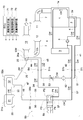
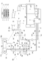
- decompression operation The figure which shows the schematic structure of the engine system of 1st Embodiment, and the flow state of the engine cooling water at the time of cooling operation.
- the DOC unit 11 is configured as an exhaust gas treatment unit in which a DOC (oxidation catalyst: Diesel Oxidation Catalyst) that oxidizes and purifies HC (hydrocarbon) and CO (carbon monoxide) in the exhaust gas EG.
- the DPF unit 12 is configured as an exhaust gas treatment unit in which a DPF (diesel particulate filter) that collects and purifies PM (particulate matter) in the exhaust gas EG is disposed.
- the SCR unit 13 is configured as an exhaust gas processing unit in which an SCR (Selective Catalytic Reduction) that selectively reduces and purifies NOx (nitrogen oxide) in the exhaust gas EG is disposed. Further, a dosing module 20 (an example of a reducing agent addition unit) that is added to the exhaust passage 7 in a form of injecting urea water UW (an example of a reducing agent) is provided on the upstream side of the SCR unit 13 in the exhaust passage 7. Yes. That is, as shown in FIG. 2, when urea water UW is injected from the dosing module 20 into the exhaust passage 7, ammonia is generated by the hydrolysis of the injected urea water UW by the heat of the exhaust gas EG. Then, in the SCR unit 13, NOx in the exhaust gas EG is selectively reduced to water and nitrogen by the reducing action of the generated ammonia, and as a result, the exhaust gas EG is purified.
- SCR Selective Catalytic Reduction
- a tank module 31 (an example of a reducing agent storage unit) that stores urea water UW supplied to the dosing module 20 is provided.
- the urea water UW stored in the tank module 31 is taken out by the supply module 32 and then supplied to the dosing module 20.
- the tank module 31 is provided with a temperature sensor 35 that measures the temperature of the stored urea water UW.
- the measurement result of the temperature sensor 35 is input to an ECU 70 (engine control unit) that controls the operation of the engine 1.
- a cooling water circuit 4 for cooling the engine 1 and the oil cooler 2 is provided on the engine 1 side.
- the engine cooling water is connected to the radiator 3 with respect to each of the cooling water channel 1 a provided in the engine 1 and the cooling water channel 2 a provided in the oil cooler 2 with the operation of the pump 5.
- CW is circulated and supplied.
- An engine side extraction pipe 41 (an example of an engine side extraction part) and an engine side return pipe 42 (an example of an engine side return part) are connected to the coolant circuit 4 on the engine 1 side. Then, the engine coolant CW is taken out from the coolant circuit 4 to the engine side extraction pipe 41. On the other hand, the engine coolant CW is returned from the engine side return pipe 42 to the coolant circuit 4.
- the engine side extraction pipe 41 is connected to, for example, the secondary side (discharge side) of the pump 5 in the cooling water circuit 4, specifically, the primary side (inflow side) of the cooling water passage 2 a of the oil cooler 2. Then, a relatively low temperature engine coolant CW is taken out from the connecting portion to the engine side take-out piping 41.
- the engine side return pipe 42 is connected to, for example, the primary side (inflow side) of the pump 5 in the cooling water circuit 4. Then, the engine coolant CW returned to the connection portion circulates through the coolant circuit 4 and flows through the radiator 3 to be appropriately cooled.
- the connection location of the engine side extraction piping 41 and the engine side return piping 42 in the cooling water circuit 4, etc. can be changed suitably.
- the dosing module 20 is provided with a cooling water passage 20a (an example of an addition part heat exchange part).
- the cooling water passage 20 a is circulated and supplied with the engine cooling water CW between the cooling water circuit 4 on the engine 1 side and performs heat exchange between the engine cooling water CW and the dosing module 20. Then, during operation of the engine 1 where the exhaust gas EG is discharged to the exhaust path 7, the engine cooling water CW flows through the cooling water path 20a, whereby the dosing module 20 is cooled by heat exchange with the engine cooling water CW. . This prevents malfunction and damage due to excessive temperature rise of the dosing module 20.
- a dosing module side supply pipe 45 (an example of an addition part side supply part) and a dosing module side discharge pipe 44 (an example of an addition part side discharge part) are connected to the cooling water channel 20a of the dosing module 20. . Then, the engine coolant CW is supplied from the dosing module side supply pipe 45 to the coolant channel 20a. On the other hand, the engine cooling water CW is discharged from the cooling water channel 20a to the dosing module side discharge pipe 44.
- the tank module 31 is provided with a cooling water channel 31a (an example of a reservoir heat exchange unit).
- the cooling water passage 31a is circulated and supplied with the engine cooling water CW between the cooling water circuit 4 on the engine 1 side, and heat exchange is performed between the engine cooling water CW and the urea water UW of the tank module 31.
- the supply module 32 is also provided with a cooling water channel 32a.
- the cooling water passage 32a is circulated and supplied with the engine cooling water CW from the cooling water circuit 4 on the engine 1 side, and heat is generated between the engine cooling water CW and the urea water UW present in the supply module 32. Exchange.
- the cooling water channel 31a of the tank module 31 and the cooling water channel 32a of the supply module 32 are connected in series with the former as the upstream side.
- the urea water UW remaining in the tank module 31 and the supply module 32 may be frozen during the starting operation.
- the urea water UW frozen in the tank module 31 and the like is heated by heat exchange with the engine cooling water CW by flowing the engine cooling water CW through these cooling water channels 31a and 32a. Will be thawed.
- the storage part side supply piping 48 (an example of the storage part side supply part) and the storage part side discharge pipe 47 (an example of the storage part side discharge part) are connected to the cooling water channels 31a and 32a of the tank module 31 and the like. ing. Then, the engine coolant CW is supplied from the reservoir side supply pipe 48 to the coolant channels 31a and 32a. On the other hand, the engine cooling water CW is discharged from the cooling water channels 31 a and 32 a to the storage portion side discharge pipe 47.
- an integrally modularized cooling water distribution module 50 is connected to each connection portion 51i, 51o, 54i, 55o, 56i, 57o provided in the cooling water distribution module 50.
- the pipes 41, 42, 44, 45, 47, and 48 through which the engine coolant CW flows in and out are connected in a form that is connected by a known pipe joint or the like.
- the cooling water distribution module 50 shown in FIGS. 1 and 2 is provided with a supply pipe 51 (an example of a supply path).
- An engine-side extraction pipe 41 is connected to a connection portion 51 i on one end side of the supply pipe 51.
- a dosing module side supply pipe 45 is connected to the connection portion 50 o on the other end side of the supply pipe 51. That is, the supply pipe 51 connects the engine side extraction pipe 41 and the dosing module side supply pipe 45. Therefore, the engine cooling water CW taken out from the cooling water circuit 4 on the engine 1 side to the engine side extraction piping 41 is introduced into the dosing module side supply piping 45 through this supply piping 51, and the cooling water channel of the dosing module 20 20a will be supplied.
- the supply pipe 51 is provided with a filter 52 that removes solid substances that cause a malfunction of a direction switching valve 59 described later.
- a flow rate adjustment valve 53 that is controlled by the ECU 70 is provided downstream of the filter 52 in the supply pipe 51.
- the flow rate adjusting valve 53 adjusts the flow rate of the engine cooling water CW supplied from the supply pipe 51 to the cooling water channel 20a of the engine cooling water CW, that is, the flow rate of the engine cooling water CW flowing through the cooling water channel 20a of the dosing module 20. Is possible.
- the cooling water distribution module 50 is provided with pipes 54, 55, 56, and 57.
- the piping 54 is configured as a piping in which the dosing module side discharge piping 44 is connected to the connecting portion 54i on one end side, and the other end side is connected to a supply port P1 of a direction switching valve 59 described later.
- the piping 55 is configured as a piping in which the storage portion side supply piping 48 is connected to the connecting portion 55o on one end side, and the other end side is connected to a discharge port P2 of a direction switching valve 59 described later.
- the pipe 56 is configured as a pipe in which the storage side discharge pipe 47 is connected to the connection part 56i on one end side, and the other end side is connected to a supply port P3 of a direction switching valve 59 described later.
- the pipe 57 is configured as a pipe in which the engine-side return pipe 42 is connected to the connection part 57o on one end side, and the other end side is connected to a discharge port P4 of a direction switching valve 59 described later.
- the cooling water distribution module 50 is provided with a direction switching valve 59 that can switch the flow direction of the engine cooling water CW.
- the direction switching valve 59 determines whether the return engine cooling water CW is supplied from the cooling water passage 20a of the dosing module 20 in a storage portion supply state (see FIG. 1) and a storage portion non-supply state ( It functions as a supply state switching means that can be switched between (see FIG. 2).
- the direction switching valve 59 has four ports P1 to P4, and is a four-port two-position electromagnetic switching valve that switches the connection state of the respective ports P1 to P4 at two positions when the solenoid is excited and demagnetized. It is configured.
- the dosing module side discharge pipe 44 is connected to the storage part side supply pipe 48 and the storage part side discharge pipe 47 is connected to the engine side return pipe 42. Therefore, the supply state of the return engine cooling water CW from the cooling water passage 20a of the dosing module 20 becomes a state of supplying the returning engine cooling water CW to the cooling water passages 31a and 32a of the tank module 31 and the like.
- the dosing module side discharge pipe 44 is connected to the engine side return pipe 42 and the storage portion side supply pipe 48 and the storage portion side discharge pipe 47 are closed. . Therefore, the supply state of the return engine cooling water CW from the cooling water passage 20a of the dosing module 20 is a state in which the cooling water passages 31a and 32a such as the tank module 31 are bypassed and returned to the cooling water circuit 4 on the engine 1 side. In the storage part supply state described above, the return engine cooling water CW from the cooling water passages 31 a and 32 a of the tank module 31 and the like to the cooling water circuit 4 on the engine 1 side flows through the pipe 57.
- this piping 57 is utilized as piping through which the return engine cooling water CW flows from the cooling water channel 20a of the dosing module 20 to the cooling water circuit 4 on the engine 1 side. That is, it can be said that a part of the circulation circuit of the engine cooling water CW for the cooling water channel 20a of the dosing module 20 and the cooling water channels 31a and 32a of the tank module 31 and the like is shared.
- the ECU 70 that controls the operation of the engine 1 functions as a freezing determination means 71, a switching control means 72, and a flow rate control means 73 by executing a predetermined program.
- the freezing determination means 71 is configured as a means for determining whether or not the urea water UW is frozen in the tank module 31. Specifically, the freezing determination means 71 determines that the temperature of the urea water UW stored in the tank module 31 measured by the temperature sensor 35 (hereinafter referred to as “measured storage temperature”) is frozen by the urea water UW. When the temperature is equal to or lower than the set temperature considered to be, the tank module 31 determines that the urea water UW is frozen.
- the freezing determination means 71 determines that the urea water UW is not frozen in the tank module 31 when the measured storage temperature exceeds the set temperature.
- the set temperature at which the urea water UW is considered to be frozen can be determined based on, for example, the freezing start temperature (about ⁇ 11 ° C.) of the urea water UW. The temperature can be increased.
- the switching control means 72 is configured as means for controlling the operation of the direction switching valve 59 which is a supply state switching means. Specifically, when the freezing determination means 71 determines that the urea water UW is frozen, the switching control means 72 switches the direction switching valve 59 to the storage part supply state (see FIG. 1) to turn the urea water. A thawing operation (an example of a reducing agent thawing operation) is executed. On the other hand, when the freezing determination means 71 determines that the urea water UW is not frozen, the switching control means 72 switches the direction switching valve 59 to the storage section non-supply state (see FIG. 2) and performs a cooling operation ( An example of the reducing agent non-thawing operation) is executed.
- the flow rate control means 73 is configured to control the opening degree of the flow rate adjustment valve 53 in accordance with such state switching of the direction switching valve 59.
- the details of the urea water thawing operation and the cooling operation will be described in order.
- the direction switching valve 59 is switched to the reservoir supply state. Then, the engine coolant CW is circulated and supplied to both the coolant channel 20a of the dosing module 20 and the coolant channels 31a and 32a such as the tank module 31. That is, the engine cooling water CW having a relatively low temperature is taken out from the cooling water circuit 4 on the engine 1 side that has been started to the engine side extraction pipe 41. The engine cooling water CW is supplied to the cooling water passage 20a of the dosing module 20 through the supply pipe 51 and the dosing module side supply pipe 45 of the cooling water distribution module 50.
- the relatively low temperature engine cooling water CW flows through the cooling water passage 20a of the dosing module 20 so that the dosing module 20 exposed to the high temperature exhaust gas EG is in contact with the relatively low temperature engine cooling water CW. It will be sufficiently cooled by heat exchange. As a result, it is possible to prevent malfunction and damage due to excessive temperature rise of the dosing module 20. Then, the relatively high-temperature engine cooling water CW heated through the cooling water passage 20a of the dosing module 20 is discharged to the dosing module side discharge pipe 44 as return engine cooling water CW.
- the relatively high-temperature return engine cooling water CW discharged to the dosing module side discharge pipe 44 is supplied from the pipe 54 of the cooling water distribution module 50, the supply port P1 and discharge port P2 of the direction switching valve 59, the pipe 55, and the storage section.
- the water is supplied to the cooling water channels 31a and 32a of the tank module 31 and the like through the side supply pipe 48.
- the relatively high temperature engine cooling water CW flows through the cooling water passages 31a and 32a of the tank module 31 and the like, so that the urea water UW frozen in the tank module 31 and the like becomes the relatively high temperature engine. It will be heated sufficiently by heat exchange with the cooling water CW.
- the urea water UW frozen in the tank module 31 or the like can be thawed in a short time.
- the engine coolant CW discharged to the storage side discharge pipe 47 after flowing through the cooling water paths 31a and 32a of the tank module 31 and the like is supplied to the pipe 56, the supply port P3 and the discharge port P4 of the direction switching valve 59, and the pipe. 57 and the engine-side return pipe 42 and then returned to the cooling water circuit 4 on the engine 1 side and appropriately cooled by the radiator 3.
- the flow rate control means 73 has a larger opening (for example, fully open) than the cooling operation described later. Status). Then, the flow rate of the engine cooling water CW flowing through the cooling water channel 20a of the dosing module 20 is set to be larger than the flow rate of the engine cooling water CW during the cooling operation described later. And the comparatively high-temperature engine cooling water CW after flowing through the cooling water channel 20a of the dosing module 20 is supplied to the cooling water channels 31a and 32a of the tank module 31 and the like at a relatively large flow rate. As a result, the urea water UW frozen in the tank module 31 or the like can be thawed in a shorter time.
- the direction switching valve 59 is switched to the reservoir non-supply state.
- the engine cooling water CW is circulated and supplied to the cooling water passage 20 a of the dosing module 20. That is, the relatively low temperature engine cooling water CW taken out from the cooling water circuit 4 on the engine 1 side in operation to the engine side extraction piping 41 passes through the supply piping 51 and the dosing module side supply piping 45 of the cooling water distribution module 50.
- the cooling water channel 20a of the dosing module 20 is supplied.
- the relatively low temperature engine cooling water CW flows through the cooling water passage 20a of the dosing module 20 so that the dosing module 20 exposed to the high temperature exhaust gas EG is in contact with the relatively low temperature engine cooling water CW.
- the relatively high-temperature return engine coolant CW discharged to the dosing module side discharge pipe 44 after flowing through the cooling water passage 20a of the dosing module 20 is supplied to the pipe 54, the supply port P1 and the discharge port P4 of the direction switching valve 59, and the pipe. 57 and the engine-side return pipe 42 and then returned to the cooling water circuit 4 on the engine 1 side and appropriately cooled by the radiator 3.
- the discharge port P2 and the supply port P3 of the direction switching valve 59 are closed, the flow of the engine cooling water CW in the cooling water passages 31a and 32a of the tank module 31 and the like is stopped. Become.
- the flow rate control means 73 sets the opening of the flow rate adjustment valve 53 to a smaller side than that during the urea water thawing operation. To do. Then, the flow rate of the engine cooling water CW flowing through the cooling water channel 20a of the dosing module 20 is set to a flow rate smaller than the flow rate of the engine cooling water CW during the urea water thawing operation. And in the dosing module 20, the engine cooling water CW having a large flow rate as in the urea water thawing operation does not flow for a long time. As a result, it is possible to suppress wear or damage of the components of the dosing module 20.
- FIGS. A second embodiment of the present invention will be described with reference to FIGS.
- the passage through which the fluid flows is shown by a thick line
- the passage through which the fluid does not flow is shown by a thin line.
- the engine system of the present embodiment differs from the engine system of the first embodiment described above only in the detailed configuration of the cooling water distribution module. Therefore, in the following description, the same components as those in the first embodiment described above are denoted by the same reference numerals in the drawings, and detailed description may be omitted.
- the cooling water distribution module 50 shown in FIG. 3 and FIG. 4 is provided with a bypass pipe 61 that connects the pipe 54 and a location on the supply pipe 51 downstream of the filter 52 and upstream of the flow rate adjustment valve 53.
- the bypass pipe 61 is provided with a bypass valve 62 that is controlled to be opened and closed by the ECU 70 and can interrupt the flow of the engine coolant CW in the bypass pipe 61.
- the switching control means 72 is comprised so that the opening / closing control of the bypass valve 62 may be performed in accordance with the operation switching between the urea water thawing operation and the cooling operation.
- the details of the urea water thawing operation and the cooling operation will be described in order.
- the remaining portion of the engine cooling water CW supplied to the supply pipe 51 of the cooling water distribution module 50 flows through the bypass pipe 61 to bypass the cooling water passage 20a of the dosing module 20 and is supplied to the pipe 54.
- the part of the engine cooling water CW flows through the cooling water passage 20a of the dosing module 20 so that the dosing module 20 exposed to the high temperature exhaust gas EG is in contact with the relatively low temperature engine cooling water CW. It will be sufficiently cooled by heat exchange. As a result, it is possible to prevent malfunction and damage due to excessive temperature rise of the dosing module 20.
- the relatively high-temperature engine cooling water CW heated through the cooling water passage 20a of the dosing module 20 is discharged to the dosing module side discharge pipe 44 as return engine cooling water CW.
- the relatively high-temperature return engine coolant CW discharged to the dosing module side discharge pipe 44 is supplied to the pipe 54 and merges with the remaining engine coolant CW supplied through the bypass pipe 61.
- the engine cooling water CW after merging is slightly lower in temperature than the engine cooling water CW discharged to the dosing module side discharge pipe 44, but is higher in temperature than the engine cooling water CW taken out from the cooling water circuit 4 on the engine 1 side. And the flow rate is increased. Then, the engine coolant CW whose flow rate has increased at a relatively high temperature flowing through the pipe 54 passes through the supply port P1 and the discharge port P2 of the direction switching valve 59, the pipe 55, and the storage section side supply pipe 48 to the tank.
- the engine coolant CW whose flow rate is increased at a relatively high temperature flows through the coolant channels 31a and 32a of the tank module 31 or the like, so that the urea water UW frozen in the tank module 31 or the like It is sufficiently heated by heat exchange with the engine cooling water CW having a high temperature. As a result, the urea water UW frozen in the tank module 31 or the like can be thawed in a shorter time.
- the flow rate control means 73 may set the opening degree of the flow rate adjustment valve 53 to a larger side than in the cooling operation as in the first embodiment, but in this embodiment, , Set the opening to the same level as during cooling operation. Then, as described above, the flow rate of the engine cooling water CW flowing through the cooling water channel 20a of the dosing module 20 is reduced while supplying a large flow rate of the engine cooling water CW to the cooling water channels 31a and 32a of the tank module 31 and the like. By setting the flow rate, wear or damage of the components of the dosing module 20 can be suppressed.
- the urea water UW is used as the reducing agent.
- other reducing agents such as ammonia water may be used.
- the cooling water channel 32a of the supply module 32 is connected in series to the cooling water channel 31a of the tank module 31 that is the reducing agent reservoir.
- the connection order of the cooling water channels 31a and 32a can be appropriately changed.
- the cooling water channels 31a and 32a may be connected in parallel.
- the cooling water channel 31 a of the tank module 31 may be provided separately from the cooling water channel 32 a of the supply module 32.
- the engine cooling water CW having a high temperature through the cooling water passage 20a of the dosing module 20 is supplied. Can do.
- the engine cooling water CW can be directly supplied from the cooling water circuit 4 on the engine 1 side to the cooling water passage 32a of the supply module 32 in which the frozen urea water UW is small.
- the frozen urea water UW in each of the modules 31 and 32 can be efficiently thawed.
- the configuration relating to the flow state of the engine cooling water CW with respect to the cooling water channels 20a, 31a, and 32a can be appropriately modified.
- the cooling water distribution module 50 that is integrally modularized is adopted.
- the direction switching valve 59 functioning as the supply state switching means and the supply pipes 51, 54, 55, 56, 57, etc. may be installed in the engine system without being modularized.
- the state of the direction switching valve 59 functioning as the supply state switching means is automatically switched, and the urea It was configured to automatically switch between water thawing operation and cooling operation.
- a user of the engine system determines whether or not the reducing agent such as the urea water UW is frozen in the reducing agent storage unit such as the tank module 31, and the direction switching valve 59 or the like.
- the supply state switching means may be manually switched.
- the supply state switching means capable of switching the supply state of the return engine cooling water CW from the cooling water passage 20a of the dosing module 20 between the storage portion supply state and the storage portion non-supply state is the 4-port 2
- the direction switching valve 59 is a position type electromagnetic switching valve.
- the supply state switching means may be configured by combining an on-off valve, a three-way valve, or the like instead of the direction switching valve 59.
- the temperature sensor 35 is provided in the tank module 31, and the freezing determination means 71 determines whether or not the urea water UW is frozen in the tank module 31 based on the measurement result of the temperature sensor 35. Configured to do. However, in the present invention, for example, it may be configured to determine whether or not the urea water UW is frozen in a form estimated from the temperature of the outside air or other parts.
- the present invention can be applied to an engine system provided with a selective reduction catalyst system including a reducing agent addition unit and a reducing agent storage unit.
Landscapes
- Engineering & Computer Science (AREA)
- Chemical & Material Sciences (AREA)
- Combustion & Propulsion (AREA)
- Mechanical Engineering (AREA)
- General Engineering & Computer Science (AREA)
- Exhaust Gas After Treatment (AREA)
Abstract
選択還元触媒システムを備えたエンジンシステムにおいて、合理的且つ簡単な構成を採用しながら、還元剤添加部を適切に冷却可能とすると共に、還元剤貯留部で凍結している還元剤を短時間で解凍可能とする技術を提供する。排気路7における選択還元触媒部13の上流側に還元剤を添加する還元剤添加部20と、還元剤添加部20に供給される還元剤を貯留する還元剤貯留部31と、還元剤添加部20に設けられた添加部熱交換部20aと、還元剤貯留部31に設けられた貯留部熱交換部31aとを備え、添加部熱交換部20aからの戻りエンジン冷却水CWの供給状態を、貯留部熱交換部31aへの往きエンジン冷却水CWとして供給する貯留部供給状態と貯留部熱交換部31aをバイパスしてエンジン1側に戻す貯留部非供給状態とで切換可能な供給状態切換手段59を備える。
Description
本発明は、エンジンから排出された排ガスが通流する排気路における選択還元触媒部の上流側に還元剤を添加する還元剤添加部と、前記還元剤添加部に供給される還元剤を貯留する還元剤貯留部と、前記還元剤添加部に設けられ、前記エンジン側との間でエンジン冷却水が循環供給されて当該エンジン冷却水と前記還元剤添加部との間で熱交換を行う添加部熱交換部と、前記還元剤貯留部に設けられ、前記エンジン側との間でエンジン冷却水が循環供給されて当該エンジン冷却水と前記還元剤貯留部の還元剤との間で熱交換を行う貯留部熱交換部とを備えたエンジンシステムに関する。
従来のエンジンシステムとして、ディーゼルエンジン等から排出される排ガス中のNOx(窒素酸化物)を還元させて当該排ガスを浄化する選択還元触媒システム(以下「SCRシステム」と呼ぶ場合がある。)を備えたものが知られている(特許文献1を参照)。
かかるSCRシステムは、尿素水などを還元剤として利用し、還元剤貯留部に貯留されている還元剤を、エンジンから排出された排ガスが通流する排気路における選択還元触媒部の上流側に、還元剤添加部から添加する。すると、選択還元触媒部において、還元剤の還元作用により、排気ガス中のNOxが選択的に水と窒素に還元され、結果、排ガスが浄化されることになる。
かかるSCRシステムは、尿素水などを還元剤として利用し、還元剤貯留部に貯留されている還元剤を、エンジンから排出された排ガスが通流する排気路における選択還元触媒部の上流側に、還元剤添加部から添加する。すると、選択還元触媒部において、還元剤の還元作用により、排気ガス中のNOxが選択的に水と窒素に還元され、結果、排ガスが浄化されることになる。
このようなSCRシステムは、高温の排ガスに晒された還元剤添加部の過剰昇温による作動不良や損傷を防止する目的で、還元剤添加部に設けられた添加部熱交換部にエンジン冷却水を循環供給して、当該還元剤添加部をエンジン冷却水との熱交換により冷却するように構成されている。また、寒冷地での始動運転時等において、還元剤貯留部で還元剤が凍結している場合には、当該凍結した還元剤を解凍する目的で、還元剤貯留部に設けられた貯留部熱交換部にエンジン冷却水を循環供給して、当該還元剤貯留部で凍結している還元剤をエンジン冷却水との熱交換により加熱し解凍するように構成されている。
また、従来のSRCシステムにおいて、貯留部熱交換部へのエンジン冷却水の循環供給は、通常運転時等に実行される添加部熱交換部へのエンジン冷却水の循環供給とは異なって、還元剤貯留部で還元剤が凍結している始動運転時等に一時的に実行されることから、これらのエンジン冷却水の循環回路は並列状態で各別に設けられている。
また、従来のSRCシステムにおいて、貯留部熱交換部へのエンジン冷却水の循環供給は、通常運転時等に実行される添加部熱交換部へのエンジン冷却水の循環供給とは異なって、還元剤貯留部で還元剤が凍結している始動運転時等に一時的に実行されることから、これらのエンジン冷却水の循環回路は並列状態で各別に設けられている。
従来のSCRシステムでは、始動運転時等において、還元剤貯留部で凍結している還元剤をエンジン冷却水との熱交換により加熱し解凍するにあたり、エンジン側でエンジン冷却水が十分に昇温されていないなどの理由で、還元剤の解凍が完了して還元剤添加部において還元剤を添加可能となるまでに要する時間が長期化するという問題がある。
また、従来のSCRシステムでは、貯留部熱交換部へのエンジン冷却水の循環供給を行うための循環回路と、添加部熱交換部へのエンジン冷却水の循環供給を行うための循環回路とが、並列状態で各別に設けられているので、構造が煩雑となり、レイアウトの自由度が制限されるという問題がある。
また、従来のSCRシステムでは、貯留部熱交換部へのエンジン冷却水の循環供給を行うための循環回路と、添加部熱交換部へのエンジン冷却水の循環供給を行うための循環回路とが、並列状態で各別に設けられているので、構造が煩雑となり、レイアウトの自由度が制限されるという問題がある。
この実情に鑑み、本発明の主たる課題は、還元剤添加部及び還元剤貯留部等からなる選択還元触媒システムを備えたエンジンシステムにおいて、合理的且つ簡単な構成を採用しながら、還元剤添加部を適切に冷却可能とすると共に、還元剤貯留部で凍結している還元剤を短時間で解凍可能とする技術を提供する点にある。
本発明の第1特徴構成は、エンジンから排出された排ガスが通流する排気路における選択還元触媒部の上流側に還元剤を添加する還元剤添加部と、
前記還元剤添加部に供給される還元剤を貯留する還元剤貯留部と、
前記還元剤添加部に設けられ、前記エンジン側との間でエンジン冷却水が循環供給されて当該エンジン冷却水と前記還元剤添加部との間で熱交換を行う添加部熱交換部と、
前記還元剤貯留部に設けられ、前記エンジン側との間でエンジン冷却水が循環供給されて当該エンジン冷却水と前記還元剤貯留部の還元剤との間で熱交換を行う貯留部熱交換部とを備えたエンジンシステムであって、
前記添加部熱交換部からの戻りエンジン冷却水の供給状態を、前記貯留部熱交換部への往きエンジン冷却水として供給する貯留部供給状態と前記貯留部熱交換部をバイパスして前記エンジン側に戻す貯留部非供給状態とで切換可能な供給状態切換手段を備えた点にある。
前記還元剤添加部に供給される還元剤を貯留する還元剤貯留部と、
前記還元剤添加部に設けられ、前記エンジン側との間でエンジン冷却水が循環供給されて当該エンジン冷却水と前記還元剤添加部との間で熱交換を行う添加部熱交換部と、
前記還元剤貯留部に設けられ、前記エンジン側との間でエンジン冷却水が循環供給されて当該エンジン冷却水と前記還元剤貯留部の還元剤との間で熱交換を行う貯留部熱交換部とを備えたエンジンシステムであって、
前記添加部熱交換部からの戻りエンジン冷却水の供給状態を、前記貯留部熱交換部への往きエンジン冷却水として供給する貯留部供給状態と前記貯留部熱交換部をバイパスして前記エンジン側に戻す貯留部非供給状態とで切換可能な供給状態切換手段を備えた点にある。
本構成によれば、上記供給状態切換手段を備えることで、添加部熱交換部及び貯留部熱交換部の夫々に対するエンジン冷却水の循環回路の一部を共通化して合理的且つ簡単な構成を採用しながら、添加部熱交換部からの戻りエンジン冷却水の供給状態を、上記貯留部供給状態と上記貯留部非供給状態とで切り換えることができる。
そして、始動運転時等において還元剤貯留部で凍結している還元剤の解凍を行う場合には、上記供給状態切換手段を上記貯留部供給状態に切り換えることで、還元剤添加部との熱交換により昇温した添加部熱交換部からの戻りエンジン冷却水を、貯留部熱交換部への往きエンジン冷却水として供給することができる。よって、貯留部熱交換部には、エンジン側から直接エンジン冷却水が循環供給される場合と比べて、比較的高温のエンジン冷却水が通流することになり、その比較的高温のエンジン冷却水との熱交換により還元剤貯留部で凍結している還元剤を短時間で解凍することができる。
そして、始動運転時等において還元剤貯留部で凍結している還元剤の解凍を行う場合には、上記供給状態切換手段を上記貯留部供給状態に切り換えることで、還元剤添加部との熱交換により昇温した添加部熱交換部からの戻りエンジン冷却水を、貯留部熱交換部への往きエンジン冷却水として供給することができる。よって、貯留部熱交換部には、エンジン側から直接エンジン冷却水が循環供給される場合と比べて、比較的高温のエンジン冷却水が通流することになり、その比較的高温のエンジン冷却水との熱交換により還元剤貯留部で凍結している還元剤を短時間で解凍することができる。
一方、始動運転時や通常運転時等において還元剤貯留部で還元剤が凍結していない場合には、上記供給状態切換手段を上記貯留部非供給状態に切り換えることで、上記還元剤添加部との熱交換により昇温した添加部熱交換部からの戻りエンジン冷却水を、貯留部熱交換部をバイパスさせてエンジン側に戻すことができる。よって、貯留部熱交換部へのエンジン冷却水の循環供給を停止しながら、添加部熱交換部へのエンジン冷却水の循環供給を継続して、比較的低温のエンジン冷却水との熱交換により還元剤添加部を適切に冷却して当該還元剤添加部の過剰昇温による作動不良や損傷を防止することができる。
従って、本発明により、還元剤添加部及び還元剤貯留部等からなる選択還元触媒システムを備えるにあたり、合理的且つ簡単な構成を採用しながら、還元剤添加部を適切に冷却可能とすると共に、還元剤貯留部で凍結している還元剤を短時間で解凍可能とするエンジンシステムを提供することができる。
従って、本発明により、還元剤添加部及び還元剤貯留部等からなる選択還元触媒システムを備えるにあたり、合理的且つ簡単な構成を採用しながら、還元剤添加部を適切に冷却可能とすると共に、還元剤貯留部で凍結している還元剤を短時間で解凍可能とするエンジンシステムを提供することができる。
本発明の第2特徴構成は、前記還元剤貯留部において還元剤が凍結しているか否かを判定する凍結判定手段と、
前記供給状態切換手段の作動を制御する切換制御手段とを備え、
前記切換制御手段が、前記凍結判定手段により還元剤が凍結していると判定された場合には、前記供給状態切換手段を前記貯留部供給状態に切り換えて、前記添加部熱交換部及び前記貯留部熱交換部の両方にエンジン冷却水を循環供給して、前記還元剤添加部の冷却と前記還元剤貯留部での還元剤の解凍を行う還元剤解凍運転を実行し、一方、前記凍結判定手段により還元剤が凍結していないと判定された場合には、前記供給状態切換手段を前記貯留部非供給状態に切り換えて、前記添加部熱交換部にエンジン冷却水を循環供給して、前記還元剤添加部の冷却を行う還元剤非解凍運転を実行する点にある。
前記供給状態切換手段の作動を制御する切換制御手段とを備え、
前記切換制御手段が、前記凍結判定手段により還元剤が凍結していると判定された場合には、前記供給状態切換手段を前記貯留部供給状態に切り換えて、前記添加部熱交換部及び前記貯留部熱交換部の両方にエンジン冷却水を循環供給して、前記還元剤添加部の冷却と前記還元剤貯留部での還元剤の解凍を行う還元剤解凍運転を実行し、一方、前記凍結判定手段により還元剤が凍結していないと判定された場合には、前記供給状態切換手段を前記貯留部非供給状態に切り換えて、前記添加部熱交換部にエンジン冷却水を循環供給して、前記還元剤添加部の冷却を行う還元剤非解凍運転を実行する点にある。
本構成によれば、上記凍結判定手段及び上記切換制御手段を備えることで、上記切り換え手段による添加部熱交換部からの戻りエンジン冷却水の供給状態の切り換え操作を自動的に実行することができる。
即ち、始動運転時等において上記凍結判定手段により還元剤が凍結していると判定された場合には、上記切換制御手段により自動的に上記供給状態切換手段が上記貯留部供給状態に切り換えられて上記還元剤解凍運転が実行されるので、添加部熱交換部を通流した後の比較的高温のエンジン冷却水との熱交換により、還元剤貯留部で凍結している還元剤を短時間で解凍することができる。
一方、始動運転時や通常運転時等において凍結判定手段により還元剤が凍結していないと判定された場合には、上記切換制御手段により自動的に上記供給状態切換手段が上記貯留部非供給状態に切り換えられて上記還元剤非解凍運転が実行されるので、エンジン側から供給された比較的低温のエンジン冷却水との熱交換により、比較的低温のエンジン冷却水との熱交換により還元剤添加部を適切に冷却して当該還元剤添加部の過剰昇温による作動不良や損傷を防止することができる。
即ち、始動運転時等において上記凍結判定手段により還元剤が凍結していると判定された場合には、上記切換制御手段により自動的に上記供給状態切換手段が上記貯留部供給状態に切り換えられて上記還元剤解凍運転が実行されるので、添加部熱交換部を通流した後の比較的高温のエンジン冷却水との熱交換により、還元剤貯留部で凍結している還元剤を短時間で解凍することができる。
一方、始動運転時や通常運転時等において凍結判定手段により還元剤が凍結していないと判定された場合には、上記切換制御手段により自動的に上記供給状態切換手段が上記貯留部非供給状態に切り換えられて上記還元剤非解凍運転が実行されるので、エンジン側から供給された比較的低温のエンジン冷却水との熱交換により、比較的低温のエンジン冷却水との熱交換により還元剤添加部を適切に冷却して当該還元剤添加部の過剰昇温による作動不良や損傷を防止することができる。
本発明の第3特徴構成は、前記エンジン側に、当該エンジン側からエンジン冷却水が取り出されるエンジン側取出部と、当該エンジン側へエンジン冷却水が戻されるエンジン側戻り部とが設けられ、
前記添加部熱交換部側に、当該添加部熱交換部へエンジン冷却水が供給される添加部側供給部と、当該添加部熱交換部からエンジン冷却水が排出される添加部側排出部とが設けられ、
前記貯留部熱交換部側に、当該貯留部熱交換部へエンジン冷却水が供給される貯留部側供給部と、当該貯留部熱交換部からエンジン冷却水が排出される貯留部側排出部とが設けられ、
前記エンジン側取出部と前記添加部側供給部とを接続する供給路を備え、
前記供給状態切換手段が、前記貯留部供給状態において、前記添加部側排出部を前記貯留部側供給部に接続すると共に前記貯留部側排出部を前記エンジン側戻り部に接続する状態となり、一方、前記貯留部非供給状態において、前記添加部側排出部を前記エンジン側戻り部に接続すると共に前記貯留部側供給部及び前記貯留部側排出部を閉鎖する状態となる方向切換弁で構成されている点にある。
前記添加部熱交換部側に、当該添加部熱交換部へエンジン冷却水が供給される添加部側供給部と、当該添加部熱交換部からエンジン冷却水が排出される添加部側排出部とが設けられ、
前記貯留部熱交換部側に、当該貯留部熱交換部へエンジン冷却水が供給される貯留部側供給部と、当該貯留部熱交換部からエンジン冷却水が排出される貯留部側排出部とが設けられ、
前記エンジン側取出部と前記添加部側供給部とを接続する供給路を備え、
前記供給状態切換手段が、前記貯留部供給状態において、前記添加部側排出部を前記貯留部側供給部に接続すると共に前記貯留部側排出部を前記エンジン側戻り部に接続する状態となり、一方、前記貯留部非供給状態において、前記添加部側排出部を前記エンジン側戻り部に接続すると共に前記貯留部側供給部及び前記貯留部側排出部を閉鎖する状態となる方向切換弁で構成されている点にある。
本構成によれば、上記供給路を備えると共に前述の供給状態切換手段として上記方向切換弁を備えることで、上記供給状態切換手段による添加部熱交換部からの戻りエンジン冷却水の供給状態の切り換え操作に必要な配管等の構成を簡略化しつつ、上記供給路及び上記方向切換弁を一体的にモジュール化された冷却水分配モジュールとして構成することができる。よって、この冷却水分配モジュールをエンジンシステムに設置する形態で、本発明の特徴構成を備えたエンジンシステムを簡単に実現することができる。
本発明の第4特徴構成は、前記供給状態切換手段を前記貯留部供給状態に切り換えたときの前記添加部熱交換部を通流するエンジン冷却水の流量を、前記供給状態切換手段を前記貯留部非供給状態に切り換えたときのエンジン冷却水の流量よりも大きく設定する流量制御手段を備えた点にある。
本構成によれば、始動運転時等において還元剤貯留部で凍結している還元剤の解凍を行う場合には、上記供給状態切換手段による上記貯留部供給状態への切り換えに伴って、上記流量制御手段により、添加部熱交換部を通流した後に貯留部熱交換部に供給されるエンジン冷却水の流量が、上記貯留部非供給状態に切り換えられたときの流量よりも大きく設定される。このことで、尿素水貯留部において、添加部熱交換部を通流した後の比較的高温で比較的大流量のエンジン冷却水との熱交換により、還元剤貯留部で凍結している還元剤をより一層短時間に解凍することができる。
一方、始動運転時や通常運転時等において還元剤貯留部で凍結している還元剤の解凍を行わない場合には、上記供給状態切換手段による上記貯留部非供給状態への切り換えに伴って、添加部熱交換部を通流した後にエンジン側に戻されるエンジン冷却水の流量が、上記貯留部供給状態に切り換えられたときの流量よりも小さく設定される。このことで、尿素水添加部において、大流量のエンジン冷却水が長時間に亘って通流することによる磨耗や損傷等を抑制することができる。
一方、始動運転時や通常運転時等において還元剤貯留部で凍結している還元剤の解凍を行わない場合には、上記供給状態切換手段による上記貯留部非供給状態への切り換えに伴って、添加部熱交換部を通流した後にエンジン側に戻されるエンジン冷却水の流量が、上記貯留部供給状態に切り換えられたときの流量よりも小さく設定される。このことで、尿素水添加部において、大流量のエンジン冷却水が長時間に亘って通流することによる磨耗や損傷等を抑制することができる。
[第1実施形態]
本発明の第1実施形態について、図1及び図2に基づいて説明する。本図において、流体が通流している通路を太線で示し、流体が通流していない通路を細線で示している。
本発明の第1実施形態について、図1及び図2に基づいて説明する。本図において、流体が通流している通路を太線で示し、流体が通流していない通路を細線で示している。
〔エンジンシステムの基本構成〕
先ず、本実施形態のエンジンシステムの基本構成について説明する。
図1及び図2に示すエンジンシステムには、レシプロ式のディーゼルエンジン1(以下単に「エンジン1」と呼ぶ。)から排気路7に排出される排ガスEG中のNOx(窒素酸化物)を還元させて当該排ガスEGを浄化するSCRシステム(選択還元触媒システム)を備える。
即ち、エンジン1から排ガスEGが排出される排気路7には、DOC部11及びDPF部12が上流側から順に配置されている。その下流側には、上記SCRシステムを構成するSCR部13(選択還元触媒部の一例)が配置されている。
先ず、本実施形態のエンジンシステムの基本構成について説明する。
図1及び図2に示すエンジンシステムには、レシプロ式のディーゼルエンジン1(以下単に「エンジン1」と呼ぶ。)から排気路7に排出される排ガスEG中のNOx(窒素酸化物)を還元させて当該排ガスEGを浄化するSCRシステム(選択還元触媒システム)を備える。
即ち、エンジン1から排ガスEGが排出される排気路7には、DOC部11及びDPF部12が上流側から順に配置されている。その下流側には、上記SCRシステムを構成するSCR部13(選択還元触媒部の一例)が配置されている。
尚、DOC部11は、排ガスEG中のHC(炭化水素)やCO(一酸化炭素)を酸化させて浄化するDOC(酸化触媒:Diesel Oxidation Catalyst)が配置された排ガス処理部として構成されている。また、DPF部12は、排ガスEG中のPM(粒子状物質)を捕集して浄化するDPF(ディーゼル微粒子捕集フィルター:Diesel Particulate Filter)が配置された排ガス処理部として構成されている。
SCR部13は、排ガスEG中のNOx(窒素酸化物)を選択的に還元させて浄化するSCR(選択還元触媒:Selective Catalytic Reduction)が配置された排ガス処理部として構成されている。
また、排気路7におけるSCR部13の上流側には、尿素水UW(還元剤の一例)を噴射する形態で排気路7に添加するドージングモジュール20(還元剤添加部の一例)が設けられている。
即ち、図2に示すように、ドージングモジュール20から排気路7に尿素水UWを噴射すると、当該噴射された尿素水UWが排ガスEGの熱により加水分解されることで、アンモニアが生成される。そして、SCR部13において、その生成されたアンモニアの還元作用により、排ガスEG中のNOxが選択的に水と窒素に還元されて、結果、排ガスEGが浄化されることになる。
また、排気路7におけるSCR部13の上流側には、尿素水UW(還元剤の一例)を噴射する形態で排気路7に添加するドージングモジュール20(還元剤添加部の一例)が設けられている。
即ち、図2に示すように、ドージングモジュール20から排気路7に尿素水UWを噴射すると、当該噴射された尿素水UWが排ガスEGの熱により加水分解されることで、アンモニアが生成される。そして、SCR部13において、その生成されたアンモニアの還元作用により、排ガスEG中のNOxが選択的に水と窒素に還元されて、結果、排ガスEGが浄化されることになる。
また、このようなSCRシステムには、ドージングモジュール20に供給される尿素水UWを貯留するタンクモジュール31(還元剤貯留部の一例)が設けられている。また、タンクモジュール31に貯留されている尿素水UWは、サプライモジュール32により取り出された後に、ドージングモジュール20に供給される。
タンクモジュール31には、貯留されている尿素水UWの温度を測定する温度センサ35が設けられている。この温度センサ35の測定結果は、エンジン1の作動を制御するECU70(エンジンコントロールユニット)に入力される。
タンクモジュール31には、貯留されている尿素水UWの温度を測定する温度センサ35が設けられている。この温度センサ35の測定結果は、エンジン1の作動を制御するECU70(エンジンコントロールユニット)に入力される。
エンジン1側には、エンジン1及びオイルクーラ2を冷却するための冷却水回路4が設けられている。この冷却水回路4では、ポンプ5の作動を伴って、エンジン1に設けられた冷却水路1a及びオイルクーラ2に設けられた冷却水路2aの夫々に対して、ラジエータ3との間でエンジン冷却水CWが循環供給される。
エンジン1側の冷却水回路4には、エンジン側取出配管41(エンジン側取出部の一例)とエンジン側戻り配管42(エンジン側戻り部の一例)とが接続されている。そして、冷却水回路4からエンジン側取出配管41へエンジン冷却水CWが取り出される。一方、エンジン側戻り配管42から冷却水回路4へエンジン冷却水CWが戻される。
エンジン1側の冷却水回路4には、エンジン側取出配管41(エンジン側取出部の一例)とエンジン側戻り配管42(エンジン側戻り部の一例)とが接続されている。そして、冷却水回路4からエンジン側取出配管41へエンジン冷却水CWが取り出される。一方、エンジン側戻り配管42から冷却水回路4へエンジン冷却水CWが戻される。
エンジン側取出配管41は、例えば、冷却水回路4におけるポンプ5の二次側(吐出側)、詳しくはオイルクーラ2の冷却水路2aの一次側(流入側)に接続されている。そして、その接続部から比較的低温のエンジン冷却水CWがエンジン側取出配管41に取り出される。
一方、エンジン側戻り配管42は、例えば、冷却水回路4におけるポンプ5の一次側(流入側)に接続されている。そして、その接続部に対して戻されたエンジン冷却水CWは冷却水回路4を循環してラジエータ3を通流し適宜冷却されることになる。尚、冷却水回路4の具体的構成や、冷却水回路4におけるエンジン側取出配管41及びエンジン側戻り配管42の接続箇所等については、適宜変更可能である。
一方、エンジン側戻り配管42は、例えば、冷却水回路4におけるポンプ5の一次側(流入側)に接続されている。そして、その接続部に対して戻されたエンジン冷却水CWは冷却水回路4を循環してラジエータ3を通流し適宜冷却されることになる。尚、冷却水回路4の具体的構成や、冷却水回路4におけるエンジン側取出配管41及びエンジン側戻り配管42の接続箇所等については、適宜変更可能である。
ドージングモジュール20には、冷却水路20a(添加部熱交換部の一例)が設けられている。この冷却水路20aは、エンジン1側の冷却水回路4との間でエンジン冷却水CWが循環供給されて、当該エンジン冷却水CWとドージングモジュール20との間で熱交換を行う。
そして、排ガスEGが排気路7に排出されるエンジン1の作動時において、冷却水路20aにエンジン冷却水CWが通流することで、ドージングモジュール20がエンジン冷却水CWとの熱交換により冷却される。このことで、ドージングモジュール20の過剰昇温による作動不良や損傷が防止されることになる。
そして、排ガスEGが排気路7に排出されるエンジン1の作動時において、冷却水路20aにエンジン冷却水CWが通流することで、ドージングモジュール20がエンジン冷却水CWとの熱交換により冷却される。このことで、ドージングモジュール20の過剰昇温による作動不良や損傷が防止されることになる。
尚、ドージングモジュール20の冷却水路20aには、ドージングモジュール側供給配管45(添加部側供給部の一例)と、ドージングモジュール側排出配管44(添加部側排出部の一例)とが接続されている。そして、ドージングモジュール側供給配管45から冷却水路20aへエンジン冷却水CWが供給される。一方、冷却水路20aからドージングモジュール側排出配管44へエンジン冷却水CWが排出される。
タンクモジュール31には、冷却水路31a(貯留部熱交換部の一例)が設けられている。この冷却水路31aは、エンジン1側の冷却水回路4とのとの間でエンジン冷却水CWが循環供給されて、当該エンジン冷却水CWとタンクモジュール31の尿素水UWとの間で熱交換を行う。
一方、サプライモジュール32にも、冷却水路32aが設けられている。この冷却水路32aは、エンジン1側の冷却水回路4とのとの間でエンジン冷却水CWが循環供給されて、当該エンジン冷却水CWとサプライモジュール32に存在する尿素水UWとの間で熱交換を行う。
これらタンクモジュール31の冷却水路31aとサプライモジュール32の冷却水路32aとは、前者を上流側として直列状態で接続されている。
一方、サプライモジュール32にも、冷却水路32aが設けられている。この冷却水路32aは、エンジン1側の冷却水回路4とのとの間でエンジン冷却水CWが循環供給されて、当該エンジン冷却水CWとサプライモジュール32に存在する尿素水UWとの間で熱交換を行う。
これらタンクモジュール31の冷却水路31aとサプライモジュール32の冷却水路32aとは、前者を上流側として直列状態で接続されている。
そして、始動運転時等においてタンクモジュール31及びサプライモジュール32(以下「タンクモジュール31等」と呼ぶ場合がある。)に残留する尿素水UWが凍結している場合がある。このような場合において、これらの冷却水路31a,32aにエンジン冷却水CWが通流することで、タンクモジュール31等で凍結している尿素水UWがエンジン冷却水CWとの熱交換により加熱されて解凍されることになる。
尚、タンクモジュール31等の冷却水路31a,32aには、貯留部側供給配管48(貯留部側供給部の一例)と貯留部側排出配管47(貯留部側排出部の一例)とが接続されている。そして、貯留部側供給配管48から冷却水路31a,32aへエンジン冷却水CWが供給される。一方、冷却水路31a,32aから貯留部側排出配管47へエンジン冷却水CWが排出される。
以上がSCRシステムを備えた本実施形態のエンジンシステムの基本構成である。そして、本実施形態のエンジンシステムには、一体的にモジュール化された冷却水分配モジュール50が、当該冷却水分配モジュール50に設けられた各接続部51i,51o,54i,55o,56i,57oに対してエンジン冷却水CWが流入出する各配管41,42,44,45,47,48を公知の管継ぎ手等により接続する形態で、設置されている。
以下、冷却水分配モジュール50の構成、及び、ECU70が機能する切換制御手段72が冷却水分配モジュール50の作動制御を伴って実行する各運転の詳細について説明する。
以下、冷却水分配モジュール50の構成、及び、ECU70が機能する切換制御手段72が冷却水分配モジュール50の作動制御を伴って実行する各運転の詳細について説明する。
〔冷却水分配モジュール〕
図1及び図2に示す冷却水分配モジュール50には、供給配管51(供給路の一例)が設けられている。この供給配管51の一端側の接続部51iには、エンジン側取出配管41が接続されている。この供給配管51の他端側の接続部50oには、ドージングモジュール側供給配管45が接続されている。即ち、この供給配管51は、エンジン側取出配管41とドージングモジュール側供給配管45とを接続するものとなる。よって、エンジン1側の冷却水回路4からエンジン側取出配管41に取り出されたエンジン冷却水CWが、この供給配管51を介してドージングモジュール側供給配管45に導入されて、ドージングモジュール20の冷却水路20aに供給されることになる。
図1及び図2に示す冷却水分配モジュール50には、供給配管51(供給路の一例)が設けられている。この供給配管51の一端側の接続部51iには、エンジン側取出配管41が接続されている。この供給配管51の他端側の接続部50oには、ドージングモジュール側供給配管45が接続されている。即ち、この供給配管51は、エンジン側取出配管41とドージングモジュール側供給配管45とを接続するものとなる。よって、エンジン1側の冷却水回路4からエンジン側取出配管41に取り出されたエンジン冷却水CWが、この供給配管51を介してドージングモジュール側供給配管45に導入されて、ドージングモジュール20の冷却水路20aに供給されることになる。
更に、供給配管51には、後述する方向切換弁59の作動不良の原因となる固形物を除去するフィルター52が設けられている。また、供給配管51におけるフィルター52の下流側には、ECU70により作動制御される流量調整弁53が設けられている。この流量調整弁53は、供給配管51からエンジン冷却水CWの冷却水路20aに供給されるエンジン冷却水CWの流量、即ちドージングモジュール20の冷却水路20aを通流するエンジン冷却水CWの流量を調整可能である。
冷却水分配モジュール50には、上記供給配管51とは別に、配管54,55,56,57が設けられている。
配管54は、一端部側の接続部54iにドージングモジュール側排出配管44が接続され、他端側が後述する方向切換弁59の供給ポートP1に接続される配管として構成されている。
配管55は、一端側の接続部55oに貯留部側供給配管48が接続され、他端側が後述する方向切換弁59の排出ポートP2に接続される配管として構成されている。
配管56は、一端側の接続部56iに貯留部側排出配管47が接続され、他端側が後述する方向切換弁59の供給ポートP3に接続される配管として構成されている。
配管57は、一端側の接続部57oにエンジン側戻り配管42が接続され、他端側が後述する方向切換弁59の排出ポートP4に接続される配管として構成されている。
配管54は、一端部側の接続部54iにドージングモジュール側排出配管44が接続され、他端側が後述する方向切換弁59の供給ポートP1に接続される配管として構成されている。
配管55は、一端側の接続部55oに貯留部側供給配管48が接続され、他端側が後述する方向切換弁59の排出ポートP2に接続される配管として構成されている。
配管56は、一端側の接続部56iに貯留部側排出配管47が接続され、他端側が後述する方向切換弁59の供給ポートP3に接続される配管として構成されている。
配管57は、一端側の接続部57oにエンジン側戻り配管42が接続され、他端側が後述する方向切換弁59の排出ポートP4に接続される配管として構成されている。
冷却水分配モジュール50には、エンジン冷却水CWの通流方向を切換可能な方向切換弁59が設けられている。詳細については後述するが、この方向切換弁59が、ドージングモジュール20の冷却水路20aからの戻りエンジン冷却水CWの供給状態を、貯留部供給状態(図1参照)と、貯留部非供給状態(図2参照)とで切換可能な供給状態切換手段として機能する。尚、方向切換弁59は、4つのポートP1~P4を有し、ソレノイドの励磁時と消磁時との2位置で夫々のポートP1~P4の接続状態を切り換える4ポート2位置式電磁切換弁で構成されている。
方向切換弁59の状態を図1に示す貯留部供給状態に切り換えると、供給ポートP1と排出ポートP2とが連通状態となり、且つ、供給ポートP3と排出ポートP4とが連通状態となる。すると、ドージングモジュール側排出配管44が接続された配管54と、貯留部側供給配管48が接続された配管55とが連通状態となる。更に、貯留部側排出配管47が接続された配管56と、エンジン側戻り配管42が接続された配管57とが連通状態となる。
即ち、この図1に示す貯留部供給状態では、ドージングモジュール側排出配管44を貯留部側供給配管48に接続すると共に、貯留部側排出配管47をエンジン側戻り配管42に接続する状態となる。よって、ドージングモジュール20の冷却水路20aからの戻りエンジン冷却水CWの供給状態が、タンクモジュール31等の冷却水路31a,32aへの往きエンジン冷却水CWとして供給する状態となる。
一方、方向切換弁59の状態を図2に示す貯留部非供給状態に切り換えると、供給ポートP1と排出ポートP4とが連通状態となり、且つ、排出ポートP2及び供給ポートP3が閉鎖状態となる。すると、貯留部側供給配管48が接続された配管55と貯留部側排出配管47が接続された配管56が接続された配管56は閉鎖された状態となる。更に、ドージングモジュール側排出配管44が接続された配管54と、エンジン側戻り配管42が接続された配管57とが連通状態となる。
即ち、この図2に示す貯留部非供給状態では、ドージングモジュール側排出配管44をエンジン側戻り配管42に接続すると共に、貯留部側供給配管48及び貯留部側排出配管47を閉鎖する状態となる。よって、ドージングモジュール20の冷却水路20aからの戻りエンジン冷却水CWの供給状態が、タンクモジュール31等の冷却水路31a,32aをバイパスしてエンジン1側の冷却水回路4に戻す状態となる。
尚、上述した貯留部供給状態において、タンクモジュール31等の冷却水路31a,32aからエンジン1側の冷却水回路4への戻りエンジン冷却水CWが配管57を通流する。そして、この貯留部非供給状態では、この配管57が、ドージングモジュール20の冷却水路20aからエンジン1側の冷却水回路4への戻りエンジン冷却水CWが通流する配管として利用されている。即ち、ドージングモジュール20の冷却水路20a及びタンクモジュール31等の冷却水路31a,32aの夫々に対するエンジン冷却水CWの循環回路の一部が共通化されていると言える。
尚、上述した貯留部供給状態において、タンクモジュール31等の冷却水路31a,32aからエンジン1側の冷却水回路4への戻りエンジン冷却水CWが配管57を通流する。そして、この貯留部非供給状態では、この配管57が、ドージングモジュール20の冷却水路20aからエンジン1側の冷却水回路4への戻りエンジン冷却水CWが通流する配管として利用されている。即ち、ドージングモジュール20の冷却水路20a及びタンクモジュール31等の冷却水路31a,32aの夫々に対するエンジン冷却水CWの循環回路の一部が共通化されていると言える。
エンジン1の作動を制御するECU70は、所定のプログラムを実行することにより、凍結判定手段71、切換制御手段72、及び、流量制御手段73として機能する。
凍結判定手段71は、タンクモジュール31において尿素水UWが凍結しているか否かを判定する手段として構成されている。具体的に、凍結判定手段71は、温度センサ35により測定されたタンクモジュール31に貯留されている尿素水UWの温度(以下「測定貯留温度」と呼ぶ。)が、当該尿素水UWが凍結していると考えられる設定温度以下である場合には、タンクモジュール31で尿素水UWが凍結していると判定する。一方、凍結判定手段71は、測定貯留温度が上記設定温度超である場合には、タンクモジュール31で尿素水UWが凍結していないと判定する。尚、上記尿素水UWが凍結していると考えられる設定温度は、例えば尿素水UWの凍結開始温度(約-11℃)を基準に決定することができ、例えば当該凍結開始温度に数℃の余裕を加えた温度とすることができる。
凍結判定手段71は、タンクモジュール31において尿素水UWが凍結しているか否かを判定する手段として構成されている。具体的に、凍結判定手段71は、温度センサ35により測定されたタンクモジュール31に貯留されている尿素水UWの温度(以下「測定貯留温度」と呼ぶ。)が、当該尿素水UWが凍結していると考えられる設定温度以下である場合には、タンクモジュール31で尿素水UWが凍結していると判定する。一方、凍結判定手段71は、測定貯留温度が上記設定温度超である場合には、タンクモジュール31で尿素水UWが凍結していないと判定する。尚、上記尿素水UWが凍結していると考えられる設定温度は、例えば尿素水UWの凍結開始温度(約-11℃)を基準に決定することができ、例えば当該凍結開始温度に数℃の余裕を加えた温度とすることができる。
切換制御手段72は、供給状態切換手段である方向切換弁59の作動を制御する手段として構成されている。具体的に、切換制御手段72は、凍結判定手段71により尿素水UWが凍結していると判定された場合には、方向切換弁59を貯留部供給状態(図1参照)に切り換えて尿素水解凍運転(還元剤解凍運転の一例)を実行する。一方、切換制御手段72は、凍結判定手段71により尿素水UWが凍結していないと判定された場合には、方向切換弁59を貯留部非供給状態(図2参照)に切り換えて冷却運転(還元剤非解凍運転の一例)を実行する。
更に、流量制御手段73は、このような方向切換弁59の状態切換に伴って、流量調整弁53の開度制御を行うように構成されている。
以下、これら尿素水解凍運転と冷却運転の詳細について順に説明する。
更に、流量制御手段73は、このような方向切換弁59の状態切換に伴って、流量調整弁53の開度制御を行うように構成されている。
以下、これら尿素水解凍運転と冷却運転の詳細について順に説明する。
(尿素水解凍運転)
尿素水解凍運転は、始動運転時等において、凍結判定手段71によりタンクモジュール31等にて尿素水UWが凍結していると判定された場合に、高温の排ガスEGに晒されたドージングモジュール20を冷却しながら、タンクモジュール31等にて凍結している尿素水UWを解凍する目的で実行される。
尿素水解凍運転は、始動運転時等において、凍結判定手段71によりタンクモジュール31等にて尿素水UWが凍結していると判定された場合に、高温の排ガスEGに晒されたドージングモジュール20を冷却しながら、タンクモジュール31等にて凍結している尿素水UWを解凍する目的で実行される。
尿素水解凍運転では、図1に示すように、方向切換弁59が貯留部供給状態に切り換えられる。すると、エンジン冷却水CWは、ドージングモジュール20の冷却水路20a及びタンクモジュール31等の冷却水路31a,32aの両方に循環供給されることになる。
即ち、始動運転されたエンジン1側の冷却水回路4からエンジン側取出配管41に比較的低温のエンジン冷却水CWが取り出される。そして、そのエンジン冷却水CWは、冷却水分配モジュール50の供給配管51及びドージングモジュール側供給配管45を通じて、ドージングモジュール20の冷却水路20aに供給される。
このように、比較的低温のエンジン冷却水CWがドージングモジュール20の冷却水路20aを通流することで、高温の排ガスEGに晒されたドージングモジュール20が当該比較的低温のエンジン冷却水CWとの熱交換により十分に冷却されることになる。このことにより、ドージングモジュール20の過剰昇温による作動不良や損傷を防止することができる。
そして、ドージングモジュール20の冷却水路20aを通流して昇温した比較的高温のエンジン冷却水CWは、戻りエンジン冷却水CWとしてドージングモジュール側排出配管44に排出される。
即ち、始動運転されたエンジン1側の冷却水回路4からエンジン側取出配管41に比較的低温のエンジン冷却水CWが取り出される。そして、そのエンジン冷却水CWは、冷却水分配モジュール50の供給配管51及びドージングモジュール側供給配管45を通じて、ドージングモジュール20の冷却水路20aに供給される。
このように、比較的低温のエンジン冷却水CWがドージングモジュール20の冷却水路20aを通流することで、高温の排ガスEGに晒されたドージングモジュール20が当該比較的低温のエンジン冷却水CWとの熱交換により十分に冷却されることになる。このことにより、ドージングモジュール20の過剰昇温による作動不良や損傷を防止することができる。
そして、ドージングモジュール20の冷却水路20aを通流して昇温した比較的高温のエンジン冷却水CWは、戻りエンジン冷却水CWとしてドージングモジュール側排出配管44に排出される。
ドージングモジュール側排出配管44に排出された比較的高温の戻りエンジン冷却水CWは、冷却水分配モジュール50の配管54、方向切換弁59の供給ポートP1及び排出ポートP2、配管55、並びに、貯留部側供給配管48を通じて、タンクモジュール31等の冷却水路31a,32aに供給される。このように、比較的高温のエンジン冷却水CWがタンクモジュール31等の冷却水路31a,32aを通流することで、タンクモジュール31等で凍結している尿素水UWは、当該比較的高温のエンジン冷却水CWとの熱交換により十分に加熱されることになる。このことにより、タンクモジュール31等で凍結している尿素水UWを短時間で解凍することができる。
そして、タンクモジュール31等の冷却水路31a,32aを通流した後に貯留部側排出配管47に排出されたエンジン冷却水CWは、配管56、方向切換弁59の供給ポートP3及び排出ポートP4、配管57、並びに、エンジン側戻り配管42を通じて、エンジン1側の冷却水回路4に戻されて、適宜ラジエータ3で冷却されることになる。
そして、タンクモジュール31等の冷却水路31a,32aを通流した後に貯留部側排出配管47に排出されたエンジン冷却水CWは、配管56、方向切換弁59の供給ポートP3及び排出ポートP4、配管57、並びに、エンジン側戻り配管42を通じて、エンジン1側の冷却水回路4に戻されて、適宜ラジエータ3で冷却されることになる。
流量制御手段73は、方向切換弁59が上記貯留部供給状態(図1参照)に切り換えられる尿素水解凍運転において、流量調整弁53の開度を後述する冷却運転時よりも大きい側(例えば全開状態)に設定する。すると、ドージングモジュール20の冷却水路20aを通流するエンジン冷却水CWの流量が、後述する冷却運転時のエンジン冷却水CWの流量よりも大きい流量に設定される。そして、タンクモジュール31等の冷却水路31a,32aには、ドージングモジュール20の冷却水路20aを通流した後の比較的高温のエンジン冷却水CWが、比較的大流量で供給される。このことにより、タンクモジュール31等で凍結している尿素水UWをより一層短時間で解凍することができる。
(冷却運転)
冷却運転は、始動運転時や通常運転時等において、凍結判定手段71によりタンクモジュール31等にて尿素水UWが凍結していない判定された場合に、高温の排ガスEGに晒されたドージングモジュール20を冷却する目的で実行される。
冷却運転は、始動運転時や通常運転時等において、凍結判定手段71によりタンクモジュール31等にて尿素水UWが凍結していない判定された場合に、高温の排ガスEGに晒されたドージングモジュール20を冷却する目的で実行される。
冷却運転では、図2に示すように、方向切換弁59が貯留部非供給状態に切り換えられる。すると、エンジン冷却水CWは、ドージングモジュール20の冷却水路20aに循環供給されることになる。
即ち、作動中のエンジン1側の冷却水回路4からエンジン側取出配管41に取り出された比較的低温のエンジン冷却水CWは、冷却水分配モジュール50の供給配管51及びドージングモジュール側供給配管45を通じて、ドージングモジュール20の冷却水路20aに供給される。
このように、比較的低温のエンジン冷却水CWがドージングモジュール20の冷却水路20aを通流することで、高温の排ガスEGに晒されたドージングモジュール20が当該比較的低温のエンジン冷却水CWとの熱交換により十分に冷却されることになる。このことにより、ドージングモジュール20の過剰昇温による作動不良や損傷を防止することができる。
そして、ドージングモジュール20の冷却水路20aを通流して昇温した比較的高温のエンジン冷却水CWは、戻りエンジン冷却水CWとしてドージングモジュール側排出配管44に排出される。
即ち、作動中のエンジン1側の冷却水回路4からエンジン側取出配管41に取り出された比較的低温のエンジン冷却水CWは、冷却水分配モジュール50の供給配管51及びドージングモジュール側供給配管45を通じて、ドージングモジュール20の冷却水路20aに供給される。
このように、比較的低温のエンジン冷却水CWがドージングモジュール20の冷却水路20aを通流することで、高温の排ガスEGに晒されたドージングモジュール20が当該比較的低温のエンジン冷却水CWとの熱交換により十分に冷却されることになる。このことにより、ドージングモジュール20の過剰昇温による作動不良や損傷を防止することができる。
そして、ドージングモジュール20の冷却水路20aを通流して昇温した比較的高温のエンジン冷却水CWは、戻りエンジン冷却水CWとしてドージングモジュール側排出配管44に排出される。
ドージングモジュール20の冷却水路20aを通流した後にドージングモジュール側排出配管44に排出された比較的高温の戻りエンジン冷却水CWは、配管54、方向切換弁59の供給ポートP1及び排出ポートP4、配管57、並びに、エンジン側戻り配管42を通じて、エンジン1側の冷却水回路4に戻されて、適宜ラジエータ3で冷却されることになる。
尚、この冷却運転では、方向切換弁59の排出ポートP2及び供給ポートP3が閉鎖状態となることから、タンクモジュール31等の冷却水路31a,32aでのエンジン冷却水CWの通流は停止状態となる。
尚、この冷却運転では、方向切換弁59の排出ポートP2及び供給ポートP3が閉鎖状態となることから、タンクモジュール31等の冷却水路31a,32aでのエンジン冷却水CWの通流は停止状態となる。
流量制御手段73は、方向切換弁59が上記貯留部非供給状態(図2参照)に切り換えられる冷却運転において、流量調整弁53の開度を前述の尿素水解凍運転時よりも小さい側に設定する。すると、ドージングモジュール20の冷却水路20aを通流するエンジン冷却水CWの流量が、前述の尿素水解凍運転時におけるエンジン冷却水CWの流量よりも小さい流量に設定される。そして、ドージングモジュール20において、上記尿素水解凍運転時のような大流量のエンジン冷却水CWが長時間に亘って通流することがなくなる。このことにより、ドージングモジュール20の構成部品の磨耗や損傷等を抑制することができる。
[第2実施形態]
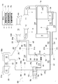
本発明の第2実施形態について、図3及び図4に基づいて説明する。本図において、流体が通流している通路を太線で示し、流体が通流していない通路を細線で示している。
尚、本実施形態のエンジンシステムは、前述の第1実施形態のエンジンシステムに対して、冷却水分配モジュールの詳細構成のみ相違する。よって、以下の説明において、前述の第1実施形態と同様の構成については、図面にて同じ符号を付すと共に、詳細な説明を割愛する場合がある。
本発明の第2実施形態について、図3及び図4に基づいて説明する。本図において、流体が通流している通路を太線で示し、流体が通流していない通路を細線で示している。
尚、本実施形態のエンジンシステムは、前述の第1実施形態のエンジンシステムに対して、冷却水分配モジュールの詳細構成のみ相違する。よって、以下の説明において、前述の第1実施形態と同様の構成については、図面にて同じ符号を付すと共に、詳細な説明を割愛する場合がある。
〔冷却水分配モジュール〕
図3及び図4に示す冷却水分配モジュール50には、供給配管51におけるフィルター52の下流側且つ流量調整弁53の上流側の箇所と配管54とを接続するバイパス配管61が設けられている。このバイパス配管61には、ECU70により開閉制御されて、当該バイパス配管61におけるエンジン冷却水CWの通流を断続可能なバイパス弁62が設けられている。
そして、切換制御手段72は、尿素水解凍運転と冷却運転との運転切り換えに伴って、バイパス弁62の開閉制御を行うように構成されている。以下、これら尿素水解凍運転と冷却運転の詳細について順に説明する。
図3及び図4に示す冷却水分配モジュール50には、供給配管51におけるフィルター52の下流側且つ流量調整弁53の上流側の箇所と配管54とを接続するバイパス配管61が設けられている。このバイパス配管61には、ECU70により開閉制御されて、当該バイパス配管61におけるエンジン冷却水CWの通流を断続可能なバイパス弁62が設けられている。
そして、切換制御手段72は、尿素水解凍運転と冷却運転との運転切り換えに伴って、バイパス弁62の開閉制御を行うように構成されている。以下、これら尿素水解凍運転と冷却運転の詳細について順に説明する。
(尿素水解凍運転)
尿素水解凍運転では、図3に示すように、バイパス弁62は開弁状態に切り換えられる。すると、エンジン1側の冷却水回路4からエンジン側取出配管41に取り出された比較的低温のエンジン冷却水CWは、冷却水分配モジュール50の供給配管51に供給される。その後に、冷却水分配モジュール50の供給配管51に供給されたエンジン冷却水CWの一部が、ドージングモジュール側供給配管45を通じてドージングモジュール20の冷却水路20aに供給される。一方、冷却水分配モジュール50の供給配管51に供給されたエンジン冷却水CWの残部が、バイパス配管61を通流してドージングモジュール20の冷却水路20aバイパスし、配管54に供給される。
このように、上記一部のエンジン冷却水CWがドージングモジュール20の冷却水路20aを通流することで、高温の排ガスEGに晒されたドージングモジュール20が当該比較的低温のエンジン冷却水CWとの熱交換により十分に冷却されることになる。このことにより、ドージングモジュール20の過剰昇温による作動不良や損傷を防止することができる。
そして、ドージングモジュール20の冷却水路20aを通流して昇温した比較的高温のエンジン冷却水CWは、戻りエンジン冷却水CWとしてドージングモジュール側排出配管44に排出される。
尿素水解凍運転では、図3に示すように、バイパス弁62は開弁状態に切り換えられる。すると、エンジン1側の冷却水回路4からエンジン側取出配管41に取り出された比較的低温のエンジン冷却水CWは、冷却水分配モジュール50の供給配管51に供給される。その後に、冷却水分配モジュール50の供給配管51に供給されたエンジン冷却水CWの一部が、ドージングモジュール側供給配管45を通じてドージングモジュール20の冷却水路20aに供給される。一方、冷却水分配モジュール50の供給配管51に供給されたエンジン冷却水CWの残部が、バイパス配管61を通流してドージングモジュール20の冷却水路20aバイパスし、配管54に供給される。
このように、上記一部のエンジン冷却水CWがドージングモジュール20の冷却水路20aを通流することで、高温の排ガスEGに晒されたドージングモジュール20が当該比較的低温のエンジン冷却水CWとの熱交換により十分に冷却されることになる。このことにより、ドージングモジュール20の過剰昇温による作動不良や損傷を防止することができる。
そして、ドージングモジュール20の冷却水路20aを通流して昇温した比較的高温のエンジン冷却水CWは、戻りエンジン冷却水CWとしてドージングモジュール側排出配管44に排出される。
ドージングモジュール側排出配管44に排出された比較的高温の戻りエンジン冷却水CWは、配管54に供給されて、バイパス配管61を通流して供給された上記残部のエンジン冷却水CWと合流する。合流後のエンジン冷却水CWは、ドージングモジュール側排出配管44に排出されたエンジン冷却水CWよりも若干低温となるものの、エンジン1側の冷却水回路4から取り出したエンジン冷却水CWよりも高温となり、且つ、流量が増加した状態となる。
そして、その配管54を通流する比較的高温で流量が増加したエンジン冷却水CWは、方向切換弁59の供給ポートP1及び排出ポートP2、配管55、並びに、貯留部側供給配管48を通じて、タンクモジュール31等の冷却水路31a,32aに供給される。
このように、比較的高温で流量が増加したエンジン冷却水CWがタンクモジュール31等の冷却水路31a,32aを通流することで、タンクモジュール31等で凍結している尿素水UWは、当該比較的高温のエンジン冷却水CWとの熱交換により十分に加熱されることになる。このことにより、タンクモジュール31等で凍結している尿素水UWを一層短時間で解凍することができる。
そして、その配管54を通流する比較的高温で流量が増加したエンジン冷却水CWは、方向切換弁59の供給ポートP1及び排出ポートP2、配管55、並びに、貯留部側供給配管48を通じて、タンクモジュール31等の冷却水路31a,32aに供給される。
このように、比較的高温で流量が増加したエンジン冷却水CWがタンクモジュール31等の冷却水路31a,32aを通流することで、タンクモジュール31等で凍結している尿素水UWは、当該比較的高温のエンジン冷却水CWとの熱交換により十分に加熱されることになる。このことにより、タンクモジュール31等で凍結している尿素水UWを一層短時間で解凍することができる。
尚、尿素水解凍運転において、流量制御手段73は、上記第1実施形態と同様に流量調整弁53の開度を冷却運転時よりも大きい側に設定しても構わないが、本実施形態では、
冷却運転時と同等の開度に設定する。すると、前述のようにタンクモジュール31等の冷却水路31a,32aに対して大流量のエンジン冷却水CWを供給しながら、ドージングモジュール20の冷却水路20aを通流するエンジン冷却水CWの流量を小さい流量に設定して、ドージングモジュール20の構成部品の磨耗や損傷等を抑制することができる。
冷却運転時と同等の開度に設定する。すると、前述のようにタンクモジュール31等の冷却水路31a,32aに対して大流量のエンジン冷却水CWを供給しながら、ドージングモジュール20の冷却水路20aを通流するエンジン冷却水CWの流量を小さい流量に設定して、ドージングモジュール20の構成部品の磨耗や損傷等を抑制することができる。
(冷却運転)
冷却運転では、図4に示すように、バイパス弁62は閉弁状態に切り換えられる。
すると、作動中のエンジン1側の冷却水回路4からエンジン側取出配管41に取り出された比較的低温のエンジン冷却水CWは、上記第1実施形態と同様に、冷却水分配モジュール50の供給配管51及びドージングモジュール側供給配管45を通じて、ドージングモジュール20の冷却水路20aに供給される。そして、ドージングモジュール20の冷却水路20aを通流して昇温した比較的高温のエンジン冷却水CWは、戻りエンジン冷却水CWとしてドージングモジュール側排出配管44に排出される。このことにより、ドージングモジュール20の過剰昇温による作動不良や損傷を防止することができる。
冷却運転では、図4に示すように、バイパス弁62は閉弁状態に切り換えられる。
すると、作動中のエンジン1側の冷却水回路4からエンジン側取出配管41に取り出された比較的低温のエンジン冷却水CWは、上記第1実施形態と同様に、冷却水分配モジュール50の供給配管51及びドージングモジュール側供給配管45を通じて、ドージングモジュール20の冷却水路20aに供給される。そして、ドージングモジュール20の冷却水路20aを通流して昇温した比較的高温のエンジン冷却水CWは、戻りエンジン冷却水CWとしてドージングモジュール側排出配管44に排出される。このことにより、ドージングモジュール20の過剰昇温による作動不良や損傷を防止することができる。
〔別実施形態〕
(1)上記実施形態では、本発明をレシプロ式のディーゼルエンジン1に適用したが、本発明を他の種類のレシプロエンジンやガスタービンエンジン等に適用しても構わない。
(1)上記実施形態では、本発明をレシプロ式のディーゼルエンジン1に適用したが、本発明を他の種類のレシプロエンジンやガスタービンエンジン等に適用しても構わない。
(2)上記実施形態では、還元剤として尿素水UWを利用したが、本発明では、アンモニア水などの他の還元剤を利用しても構わない。
(3)上記実施形態では、還元剤貯留部であるタンクモジュール31の冷却水路31aに対して、サプライモジュール32の冷却水路32aを直列状態で接続した。しかし、本発明では、これら冷却水路31a,32aの接続順序については適宜変更可能であり、例えば、これら冷却水路31a,32aを並列状態で接続しても構わない。
また、タンクモジュール31の冷却水路31aを、サプライモジュール32の冷却水路32aとは別に設けても構わない。この場合には、凍結状態の尿素水UWが多く存在するタンクモジュール31の冷却水路31aに対しては、ドージングモジュール20の冷却水路20aを通流して高温となったエンジン冷却水CWを供給することができる。一方、凍結状態の尿素水UWが少ないサプライモジュール32の冷却水路32aに対しては、エンジン1側の冷却水回路4から直接エンジン冷却水CWを供給することができる。このことで、夫々のモジュール31,32における凍結状態の尿素水UWの解凍を効率良く実施することもできる。
尚、上記構成以外にも、各冷却水路20a,31a,32aに対するエンジン冷却水CWの通流状態に関する構成については、適宜改変可能である。
また、タンクモジュール31の冷却水路31aを、サプライモジュール32の冷却水路32aとは別に設けても構わない。この場合には、凍結状態の尿素水UWが多く存在するタンクモジュール31の冷却水路31aに対しては、ドージングモジュール20の冷却水路20aを通流して高温となったエンジン冷却水CWを供給することができる。一方、凍結状態の尿素水UWが少ないサプライモジュール32の冷却水路32aに対しては、エンジン1側の冷却水回路4から直接エンジン冷却水CWを供給することができる。このことで、夫々のモジュール31,32における凍結状態の尿素水UWの解凍を効率良く実施することもできる。
尚、上記構成以外にも、各冷却水路20a,31a,32aに対するエンジン冷却水CWの通流状態に関する構成については、適宜改変可能である。
(4)上記実施形態では、一体的にモジュール化された冷却水分配モジュール50を採用したが、本発明では、供給状態切換手段として機能する方向切換弁59や各供給配管51,54,55,56,57等を、モジュール化することなくエンジンシステムに設置しても構わない。
(5)上記実施形態では、ECU70が機能する形態で凍結判定手段71や切換制御手段72等を設けることで、供給状態切換手段として機能する方向切換弁59の状態を自動的に切り換えて、尿素水解凍運転と冷却運転との運転切り換えを自動的に行うように構成した。しかし、本発明では、例えばエンジンシステムの利用者等が、タンクモジュール31等の還元剤貯留部で尿素水UW等の還元剤が凍結しているか否かを自ら判断して、方向切換弁59等の供給状態切換手段を手動で切り換えるように構成しても構わない。
(6)上記実施形態では、ドージングモジュール20の冷却水路20aからの戻りエンジン冷却水CWの供給状態を貯留部供給状態と貯留部非供給状態とで切換可能な供給状態切換手段を、4ポート2位置式電磁切換弁で構成された方向切換弁59で構成した。しかし、本発明では、方向切換弁59の代わりに、開閉弁や三方弁等を組み合わせて、供給状態切換手段を構成しても構わない。
(7)上記実施形態では、タンクモジュール31に温度センサ35を設け、凍結判定手段71は、その温度センサ35の測定結果に基づいてタンクモジュール31において尿素水UWが凍結しているか否かを判定するように構成した。しかし、本発明では、例えば外気や他の部位の温度から推定する形態で、尿素水UWが凍結しているか否かを判定するように構成しても構わない。
本発明は、還元剤添加部及び還元剤貯留部等からなる選択還元触媒システムを備えたエンジンシステムに適用できる。
1 ディーゼルエンジン(エンジン)
7 排気路
13 SCR部(選択還元触媒部)
20 ドージングモジュール(還元剤添加部)
20a 冷却水路(添加部熱交換部)
31 タンクモジュール(還元剤貯留部)
31a 冷却水路(貯留部熱交換部)
41 エンジン側取出配管(エンジン側取出部)
42 エンジン側戻り配管(エンジン側戻り部)
44 ドージングモジュール側排出配管(添加部側排出部)
45 ドージングモジュール側供給配管(添加部側供給部)
47 貯留部側排出配管(貯留部側排出部)
48 貯留部側供給配管(貯留部側供給部)
50 冷却水分配モジュール
51 供給配管(供給路)
53 流量調整弁(流量制御手段)
59 方向切換弁(供給状態切換手段)
71 凍結判定手段
72 切換制御手段
73 流量制御手段
CW エンジン冷却水
EG 排ガス
UW 尿素水(還元剤)
7 排気路
13 SCR部(選択還元触媒部)
20 ドージングモジュール(還元剤添加部)
20a 冷却水路(添加部熱交換部)
31 タンクモジュール(還元剤貯留部)
31a 冷却水路(貯留部熱交換部)
41 エンジン側取出配管(エンジン側取出部)
42 エンジン側戻り配管(エンジン側戻り部)
44 ドージングモジュール側排出配管(添加部側排出部)
45 ドージングモジュール側供給配管(添加部側供給部)
47 貯留部側排出配管(貯留部側排出部)
48 貯留部側供給配管(貯留部側供給部)
50 冷却水分配モジュール
51 供給配管(供給路)
53 流量調整弁(流量制御手段)
59 方向切換弁(供給状態切換手段)
71 凍結判定手段
72 切換制御手段
73 流量制御手段
CW エンジン冷却水
EG 排ガス
UW 尿素水(還元剤)
Claims (4)
- エンジンから排出された排ガスが通流する排気路における選択還元触媒部の上流側に還元剤を添加する還元剤添加部と、
前記還元剤添加部に供給される還元剤を貯留する還元剤貯留部と、
前記還元剤添加部に設けられ、前記エンジン側との間でエンジン冷却水が循環供給されて当該エンジン冷却水と前記還元剤添加部との間で熱交換を行う添加部熱交換部と、
前記還元剤貯留部に設けられ、前記エンジン側との間でエンジン冷却水が循環供給されて当該エンジン冷却水と前記還元剤貯留部の還元剤との間で熱交換を行う貯留部熱交換部とを備えたエンジンシステムであって、
前記添加部熱交換部からの戻りエンジン冷却水の供給状態を、前記貯留部熱交換部への往きエンジン冷却水として供給する貯留部供給状態と前記貯留部熱交換部をバイパスして前記エンジン側に戻す貯留部非供給状態とで切換可能な供給状態切換手段を備えたエンジンシステム。 - 前記還元剤貯留部において還元剤が凍結しているか否かを判定する凍結判定手段と、
前記供給状態切換手段の作動を制御する切換制御手段とを備え、
前記切換制御手段が、前記凍結判定手段により還元剤が凍結していると判定された場合には、前記供給状態切換手段を前記貯留部供給状態に切り換えて、前記添加部熱交換部及び前記貯留部熱交換部の両方にエンジン冷却水を循環供給して、前記還元剤添加部の冷却と前記還元剤貯留部での還元剤の解凍を行う還元剤解凍運転を実行し、一方、前記凍結判定手段により還元剤が凍結していないと判定された場合には、前記供給状態切換手段を前記貯留部非供給状態に切り換えて、前記添加部熱交換部にエンジン冷却水を循環供給して、前記還元剤添加部の冷却を行う還元剤非解凍運転を実行する請求項1に記載のエンジンシステム。 - 前記エンジン側に、当該エンジン側からエンジン冷却水が取り出されるエンジン側取出部と、当該エンジン側へエンジン冷却水が戻されるエンジン側戻り部とが設けられ、
前記添加部熱交換部側に、当該添加部熱交換部へエンジン冷却水が供給される添加部側供給部と、当該添加部熱交換部からエンジン冷却水が排出される添加部側排出部とが設けられ、
前記貯留部熱交換部側に、当該貯留部熱交換部へエンジン冷却水が供給される貯留部側供給部と、当該貯留部熱交換部からエンジン冷却水が排出される貯留部側排出部とが設けられ、
前記エンジン側取出部と前記添加部側供給部とを接続する供給路を備え、
前記供給状態切換手段が、前記貯留部供給状態において、前記添加部側排出部を前記貯留部側供給部に接続すると共に前記貯留部側排出部を前記エンジン側戻り部に接続する状態となり、一方、前記貯留部非供給状態において、前記添加部側排出部を前記エンジン側戻り部に接続すると共に前記貯留部側供給部及び前記貯留部側排出部を閉鎖する状態となる方向切換弁で構成されている請求項1又は2に記載のエンジンシステム。 - 前記供給状態切換手段を前記貯留部供給状態に切り換えたときの前記添加部熱交換部を通流するエンジン冷却水の流量を、前記供給状態切換手段を前記貯留部非供給状態に切り換えたときのエンジン冷却水の流量よりも大きく設定する流量制御手段を備えた請求項1~3の何れか1項に記載のエンジンシステム。
Applications Claiming Priority (2)
| Application Number | Priority Date | Filing Date | Title |
|---|---|---|---|
| JP2017085839A JP6748023B2 (ja) | 2017-04-25 | 2017-04-25 | エンジンシステム |
| JP2017-085839 | 2017-04-25 |
Publications (1)
| Publication Number | Publication Date |
|---|---|
| WO2018198554A1 true WO2018198554A1 (ja) | 2018-11-01 |
Family
ID=63920238
Family Applications (1)
| Application Number | Title | Priority Date | Filing Date |
|---|---|---|---|
| PCT/JP2018/009619 Ceased WO2018198554A1 (ja) | 2017-04-25 | 2018-03-13 | エンジンシステム |
Country Status (2)
| Country | Link |
|---|---|
| JP (1) | JP6748023B2 (ja) |
| WO (1) | WO2018198554A1 (ja) |
Citations (5)
| Publication number | Priority date | Publication date | Assignee | Title |
|---|---|---|---|---|
| JP2008101535A (ja) * | 2006-10-19 | 2008-05-01 | Denso Corp | エンジンの排気浄化装置 |
| JP2009097479A (ja) * | 2007-10-19 | 2009-05-07 | Bosch Corp | 還元剤供給装置の制御装置及び制御方法 |
| JP2009185755A (ja) * | 2008-02-08 | 2009-08-20 | Bosch Corp | 温度センサの合理性診断装置及び合理性診断方法、並びに内燃機関の排気浄化装置 |
| JP2012007511A (ja) * | 2010-06-23 | 2012-01-12 | Hino Motors Ltd | 排気浄化装置 |
| JP2014005786A (ja) * | 2012-06-26 | 2014-01-16 | Hino Motors Ltd | 冷却水循環装置 |
-
2017
- 2017-04-25 JP JP2017085839A patent/JP6748023B2/ja not_active Expired - Fee Related
-
2018
- 2018-03-13 WO PCT/JP2018/009619 patent/WO2018198554A1/ja not_active Ceased
Patent Citations (5)
| Publication number | Priority date | Publication date | Assignee | Title |
|---|---|---|---|---|
| JP2008101535A (ja) * | 2006-10-19 | 2008-05-01 | Denso Corp | エンジンの排気浄化装置 |
| JP2009097479A (ja) * | 2007-10-19 | 2009-05-07 | Bosch Corp | 還元剤供給装置の制御装置及び制御方法 |
| JP2009185755A (ja) * | 2008-02-08 | 2009-08-20 | Bosch Corp | 温度センサの合理性診断装置及び合理性診断方法、並びに内燃機関の排気浄化装置 |
| JP2012007511A (ja) * | 2010-06-23 | 2012-01-12 | Hino Motors Ltd | 排気浄化装置 |
| JP2014005786A (ja) * | 2012-06-26 | 2014-01-16 | Hino Motors Ltd | 冷却水循環装置 |
Also Published As
| Publication number | Publication date |
|---|---|
| JP6748023B2 (ja) | 2020-08-26 |
| JP2018184857A (ja) | 2018-11-22 |
Similar Documents
| Publication | Publication Date | Title |
|---|---|---|
| JP5573351B2 (ja) | Scrシステム | |
| JP4706660B2 (ja) | 還元剤供給装置 | |
| JP5787994B2 (ja) | 冷機運転時および/または暖機運転時の冷却用の冷媒集合管を備えた内燃機関 | |
| EP2998536B1 (en) | An arrangement and a control method of an engine cooling system | |
| JP4802811B2 (ja) | エンジンの冷却水回路 | |
| JP2008274900A (ja) | 内燃機関の冷却系装置 | |
| US20130000729A1 (en) | Def pump and tank thawing system and method | |
| EP3249185B1 (en) | Exhaust purification device for engine | |
| JP2010038072A (ja) | 内燃機関用排気処理装置 | |
| JP5593139B2 (ja) | 排気浄化装置 | |
| CN105626203A (zh) | 一种scr尿素加热/冷却系统及方法 | |
| JP6748023B2 (ja) | エンジンシステム | |
| US20150322840A1 (en) | Supply system for a medium into an exhaust system | |
| US10202881B2 (en) | Integration of exhaust gas recirculation (EGR), exhaust heat recovery (EHRS), and latent heat storage in a complete exhaust thermal management module | |
| US10975749B2 (en) | Systems and methods for heating reductant | |
| JP4089380B2 (ja) | エンジン冷却水回路 | |
| JP5918474B2 (ja) | Egr装置 | |
| JP2016135997A (ja) | 内燃機関の冷却システム、内燃機関及び内燃機関の冷却方法 | |
| JP5907275B2 (ja) | 内燃機関の冷却装置 | |
| CN115038856B (zh) | 车辆的还原剂解冻装置 | |
| KR102335346B1 (ko) | 냉각수 유량 제어 방법 | |
| CN221315707U (zh) | 混动车辆的热管理系统、及混动车辆 | |
| JP2007024022A (ja) | 排気浄化装置 | |
| EP3084160B1 (en) | Urea delivery system for scr system | |
| JP2015017576A (ja) | 還元剤供給装置 |
Legal Events
| Date | Code | Title | Description |
|---|---|---|---|
| 121 | Ep: the epo has been informed by wipo that ep was designated in this application |
Ref document number: 18790898 Country of ref document: EP Kind code of ref document: A1 |
|
| NENP | Non-entry into the national phase |
Ref country code: DE |
|
| 122 | Ep: pct application non-entry in european phase |
Ref document number: 18790898 Country of ref document: EP Kind code of ref document: A1 |