WO2018194137A1 - 情報処理装置、情報処理方法、及びプログラム - Google Patents
情報処理装置、情報処理方法、及びプログラム Download PDFInfo
- Publication number
- WO2018194137A1 WO2018194137A1 PCT/JP2018/016196 JP2018016196W WO2018194137A1 WO 2018194137 A1 WO2018194137 A1 WO 2018194137A1 JP 2018016196 W JP2018016196 W JP 2018016196W WO 2018194137 A1 WO2018194137 A1 WO 2018194137A1
- Authority
- WO
- WIPO (PCT)
- Prior art keywords
- related person
- virtual space
- information
- person
- time
- Prior art date
Links
- 230000010365 information processing Effects 0.000 title claims description 56
- 238000003672 processing method Methods 0.000 title claims description 7
- 238000010276 construction Methods 0.000 claims abstract description 122
- 238000012545 processing Methods 0.000 claims description 50
- 238000012423 maintenance Methods 0.000 abstract description 31
- 238000007689 inspection Methods 0.000 abstract description 29
- 230000008859 change Effects 0.000 abstract description 28
- 238000013461 design Methods 0.000 abstract description 26
- 230000006870 function Effects 0.000 description 98
- 238000000034 method Methods 0.000 description 85
- 230000008569 process Effects 0.000 description 73
- 238000004891 communication Methods 0.000 description 51
- 238000010586 diagram Methods 0.000 description 27
- 238000003860 storage Methods 0.000 description 17
- 230000033001 locomotion Effects 0.000 description 16
- 238000012790 confirmation Methods 0.000 description 14
- 238000007726 management method Methods 0.000 description 12
- 210000003128 head Anatomy 0.000 description 11
- 230000005540 biological transmission Effects 0.000 description 6
- 230000004397 blinking Effects 0.000 description 6
- 238000005516 engineering process Methods 0.000 description 6
- 125000002066 L-histidyl group Chemical group [H]N1C([H])=NC(C([H])([H])[C@](C(=O)[*])([H])N([H])[H])=C1[H] 0.000 description 5
- 230000006872 improvement Effects 0.000 description 4
- 238000001514 detection method Methods 0.000 description 3
- 230000001133 acceleration Effects 0.000 description 2
- 230000003190 augmentative effect Effects 0.000 description 2
- 239000000463 material Substances 0.000 description 2
- 238000004088 simulation Methods 0.000 description 2
- 238000012360 testing method Methods 0.000 description 2
- 230000000007 visual effect Effects 0.000 description 2
- 241000282414 Homo sapiens Species 0.000 description 1
- 238000007796 conventional method Methods 0.000 description 1
- 238000012937 correction Methods 0.000 description 1
- 238000003745 diagnosis Methods 0.000 description 1
- 210000005069 ears Anatomy 0.000 description 1
- 230000001747 exhibiting effect Effects 0.000 description 1
- 239000000284 extract Substances 0.000 description 1
- 230000014509 gene expression Effects 0.000 description 1
- XEEYBQQBJWHFJM-UHFFFAOYSA-N iron Substances [Fe] XEEYBQQBJWHFJM-UHFFFAOYSA-N 0.000 description 1
- 229910052742 iron Inorganic materials 0.000 description 1
- 239000004973 liquid crystal related substance Substances 0.000 description 1
- 238000004519 manufacturing process Methods 0.000 description 1
- 238000012986 modification Methods 0.000 description 1
- 230000004048 modification Effects 0.000 description 1
- 230000003287 optical effect Effects 0.000 description 1
- 230000009467 reduction Effects 0.000 description 1
- 230000003014 reinforcing effect Effects 0.000 description 1
- 239000004065 semiconductor Substances 0.000 description 1
- 238000004904 shortening Methods 0.000 description 1
- 210000003454 tympanic membrane Anatomy 0.000 description 1
- 230000016776 visual perception Effects 0.000 description 1
Images


Classifications
-
- G—PHYSICS
- G06—COMPUTING; CALCULATING OR COUNTING
- G06Q—INFORMATION AND COMMUNICATION TECHNOLOGY [ICT] SPECIALLY ADAPTED FOR ADMINISTRATIVE, COMMERCIAL, FINANCIAL, MANAGERIAL OR SUPERVISORY PURPOSES; SYSTEMS OR METHODS SPECIALLY ADAPTED FOR ADMINISTRATIVE, COMMERCIAL, FINANCIAL, MANAGERIAL OR SUPERVISORY PURPOSES, NOT OTHERWISE PROVIDED FOR
- G06Q50/00—Information and communication technology [ICT] specially adapted for implementation of business processes of specific business sectors, e.g. utilities or tourism
- G06Q50/08—Construction
-
- G—PHYSICS
- G06—COMPUTING; CALCULATING OR COUNTING
- G06T—IMAGE DATA PROCESSING OR GENERATION, IN GENERAL
- G06T19/00—Manipulating 3D models or images for computer graphics
- G06T19/003—Navigation within 3D models or images
-
- G—PHYSICS
- G06—COMPUTING; CALCULATING OR COUNTING
- G06F—ELECTRIC DIGITAL DATA PROCESSING
- G06F3/00—Input arrangements for transferring data to be processed into a form capable of being handled by the computer; Output arrangements for transferring data from processing unit to output unit, e.g. interface arrangements
- G06F3/01—Input arrangements or combined input and output arrangements for interaction between user and computer
- G06F3/011—Arrangements for interaction with the human body, e.g. for user immersion in virtual reality
-
- G—PHYSICS
- G06—COMPUTING; CALCULATING OR COUNTING
- G06F—ELECTRIC DIGITAL DATA PROCESSING
- G06F3/00—Input arrangements for transferring data to be processed into a form capable of being handled by the computer; Output arrangements for transferring data from processing unit to output unit, e.g. interface arrangements
- G06F3/01—Input arrangements or combined input and output arrangements for interaction between user and computer
- G06F3/048—Interaction techniques based on graphical user interfaces [GUI]
- G06F3/0481—Interaction techniques based on graphical user interfaces [GUI] based on specific properties of the displayed interaction object or a metaphor-based environment, e.g. interaction with desktop elements like windows or icons, or assisted by a cursor's changing behaviour or appearance
- G06F3/04815—Interaction with a metaphor-based environment or interaction object displayed as three-dimensional, e.g. changing the user viewpoint with respect to the environment or object
-
- G—PHYSICS
- G06—COMPUTING; CALCULATING OR COUNTING
- G06F—ELECTRIC DIGITAL DATA PROCESSING
- G06F30/00—Computer-aided design [CAD]
- G06F30/10—Geometric CAD
- G06F30/13—Architectural design, e.g. computer-aided architectural design [CAAD] related to design of buildings, bridges, landscapes, production plants or roads
-
- G—PHYSICS
- G06—COMPUTING; CALCULATING OR COUNTING
- G06Q—INFORMATION AND COMMUNICATION TECHNOLOGY [ICT] SPECIALLY ADAPTED FOR ADMINISTRATIVE, COMMERCIAL, FINANCIAL, MANAGERIAL OR SUPERVISORY PURPOSES; SYSTEMS OR METHODS SPECIALLY ADAPTED FOR ADMINISTRATIVE, COMMERCIAL, FINANCIAL, MANAGERIAL OR SUPERVISORY PURPOSES, NOT OTHERWISE PROVIDED FOR
- G06Q10/00—Administration; Management
- G06Q10/06—Resources, workflows, human or project management; Enterprise or organisation planning; Enterprise or organisation modelling
- G06Q10/063—Operations research, analysis or management
- G06Q10/0631—Resource planning, allocation, distributing or scheduling for enterprises or organisations
- G06Q10/06313—Resource planning in a project environment
-
- G—PHYSICS
- G06—COMPUTING; CALCULATING OR COUNTING
- G06Q—INFORMATION AND COMMUNICATION TECHNOLOGY [ICT] SPECIALLY ADAPTED FOR ADMINISTRATIVE, COMMERCIAL, FINANCIAL, MANAGERIAL OR SUPERVISORY PURPOSES; SYSTEMS OR METHODS SPECIALLY ADAPTED FOR ADMINISTRATIVE, COMMERCIAL, FINANCIAL, MANAGERIAL OR SUPERVISORY PURPOSES, NOT OTHERWISE PROVIDED FOR
- G06Q10/00—Administration; Management
- G06Q10/10—Office automation; Time management
- G06Q10/103—Workflow collaboration or project management
-
- G—PHYSICS
- G06—COMPUTING; CALCULATING OR COUNTING
- G06T—IMAGE DATA PROCESSING OR GENERATION, IN GENERAL
- G06T15/00—3D [Three Dimensional] image rendering
- G06T15/10—Geometric effects
- G06T15/20—Perspective computation
-
- G—PHYSICS
- G06—COMPUTING; CALCULATING OR COUNTING
- G06T—IMAGE DATA PROCESSING OR GENERATION, IN GENERAL
- G06T19/00—Manipulating 3D models or images for computer graphics
Definitions
- the present invention relates to an information processing apparatus, an information processing method, and a program.
- the present invention has been made in view of such a situation, and an object thereof is to provide a technique for supporting the creation and execution of a more efficient work plan.
- a real object for example, a bridge or the like
- a direction of at least one dimension for example, a time axis direction or a company axis direction
- n dimensions is an integer value of 2 or more.
- coordinate acquisition means for example, the time information acquisition unit 100 in FIG.
- An image generation unit (for example, an image generation unit that generates data of an image that can be viewed from a predetermined viewpoint in the virtual space in which the object corresponding to the real object in the coordinate of the acquired dimension is arranged by the arrangement unit.
- the information processing method and program of one aspect of the present invention are a method and program corresponding to the information processing apparatus of one aspect of the present invention.
- FIG. 1 It is a figure which shows the structure of the information processing system which concerns on one Embodiment of this invention. It is a figure which shows an example of the whole image of the function which the information processing system of FIG. 1 can implement
- achieving a display image generation process among the functional structures of the server of FIG. 5, and HMD of FIG. 6 is a flowchart for explaining a flow of display image generation processing executed by the server of FIG. 5. It is a figure which shows the various information stored in the object DB of the server / HMD of FIG. 7, and is a figure which shows an example different from FIG. It is a figure for demonstrating the relationship with the layer displayed in each period. It is a figure which shows an example of the basic function which can implement
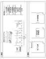
- FIG. 1 is a diagram showing a configuration of an information processing system according to an embodiment of the present invention.
- the present service a service to which an information processing system according to an embodiment of the present invention is applied will be briefly described.
- This service is the following service.
- this service is a service that allows the parties concerned for a given construction project to check various construction processes while experiencing the construction status and the completion status of the target building in the construction project. It is a service.
- the present service can be provided to one or more arbitrary parties.
- the service will be described below using an example provided to two parties Ua and Ub shown in FIG.
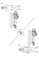
- each of the related parties Ua and Ub when receiving this service, wears HMDs (Head Mounted Displays) 2a and 2b on their heads and, if necessary, the controllers 3a and 3b. Hold each one in hand.
- HMDs Head Mounted Displays
- controllers 3a and 3b when it is not necessary to distinguish between the related parties Ua and Ub, they are collectively referred to as “related party U”.
- HMD2 When collectively calling the related person U, the HMDs 2a and 2b are collectively referred to as “HMD2”, and the controllers 3a and 3b are collectively referred to as “controller 3”.
- the person U wearing the HMD 2 can see the target building (hereinafter referred to as “bridge” as an example) in the construction business and its surroundings when it is located at the actual predetermined location and turned in the predetermined direction. You can experience the visual perception of the scenery.
- the image that the person concerned U visually recognizes through the HMD 2 is a state in which the 3D object corresponding to the actual bridge is arranged in the virtual space corresponding to the real space and the position at the predetermined location in the virtual space. It is an image equivalent to that captured from a viewpoint in a predetermined direction.
- the term “image” simply includes both “moving image” and “still image”.
- the image is not limited to a CG (Computer Graphics) image (computer graphics image) or an AR (Augmented Reality) image (augmented reality image), and may include an image in which a real space is actually captured.
- the person concerned U can issue an instruction to change the time in the virtual space by operating the controller 3. That is, the bridge is constructed over a predetermined period. The bridge at a predetermined time within this predetermined period is in an incomplete state under construction. Therefore, when the predetermined time is designated by the concerned person U, in the virtual space in which the 3D object corresponding to the bridge that is in an incomplete state of construction is arranged, the predetermined position is moved in the predetermined direction. An image equivalent to that captured from the viewpoint is visually recognized by the person U wearing the HMD 2.
- the 3D object of the bridge in the virtual space in this service changes with time according to the construction state in various construction processes. Therefore, the person concerned U can visually recognize the construction status of the bridge at an arbitrary time (the construction process scheduled or carried out at the time). In other words, the person concerned U can visually confirm the image of the construction status of the construction site including the bridge where the construction is scheduled, by moving forward or backward in time.
- the related person U moves the existence position (actual predetermined place) in the real space and moves his / her head to change the direction of the line of sight (predetermined direction), thereby It is possible to change the scenery image (the image that the person concerned U visually recognizes through his / her own naked eye).
- the person U wearing the HMD 2 moves the presence position (position in the virtual space corresponding to a predetermined place in the real space) in the virtual space, moves his / her head and moves the direction of the line of sight ( By changing the (predetermined direction), it is possible to change the image of the bridge and the surrounding scenery (image that the person concerned U visually recognizes through the HMD 2).
- the parties Ua and Ub both correspond to the situation of the construction site including the bridge that can be seen when facing the desired direction at the desired standing position with respect to the scenery of the construction site in the desired construction process.
- Each of the images) can be visually recognized.
- the persons concerned Ua and Ub can share the image of the construction site in arbitrary construction processes, and can aim at communication smoothly.
- the information processing system of FIG. 1 to which the present service is applied is used by the server 1 used by the provider of the service, the HMD 2a and the controller 3a used by the related person Ua, and the related person Ub. HMD2b and controller 3b.
- the server 1, the HMD 2a, and the HMD 2b are connected to each other via a predetermined network N such as the Internet.
- the HMD 2a and the controller 3a, and the HMD 2b and the controller 3b are connected by Bluetooth (registered trademark) or the like.
- FIG. 2 is a diagram showing an example of an overall image of functions that can be realized by the information processing system of FIG.
- Each function that can be operated or browsed by the person U wearing the HMD 2 is provided by each menu.
- FIG. 2 an example of a “TOP menu” for transitioning to each menu is shown.
- the following five menus are prepared as menus that can be changed from the “TOP menu”. That is, a plan menu, a design change menu, an inspection menu, a maintenance menu, and a communication menu are prepared.
- 3 and 4 are diagrams illustrating an example of an inspection menu that can provide the service among the menus illustrated in FIG.
- the person U wearing the HMD 2 uses the controller 3 to select the inspection menu shown in FIG. 3 and FIG. 4 and perform various operations and inspections, so that various conditions of each construction process when performing construction inspection. Can be confirmed easily and reliably.
- a time slider function is provided as a part of this service.
- the time slider function refers to the following functions. In other words, a period in which the 3D data such as a 3D object such as a building (bridge in this example) is arranged in the virtual space is given as a time attribute. Therefore, the person U wearing the HMD 2 designates the time (time point) on the time axis in the process chart showing the construction process of the building.
- 3D data to which a time attribute of a period including a designated time (time point) is given is arranged in the virtual space.
- the person concerned U can visually recognize the 3D data arranged in the virtual space from a desired viewpoint at a desired standing position.
- a 3D object or the like corresponding to a building (bridge) at a specified process stage among the past, present, and future within a predetermined period in the process chart appears in the virtual space in the HMD2. It will be.
- various functions are exhibited in the inspection menu.
- a function shown in FIG. 3 is exerted, in order to select a 3D object (design drawing 3D hologram) corresponding to a completed bridge (building) and various confirmation documents for completion inspection in the virtual space.
- An inspection document menu in which each item is listed is arranged. Items include construction plans, process management, stage confirmations, material confirmations, quality management, product management, photo management, and safety management. The person concerned U can visually recognize the inspection document (data) corresponding to the desired item by selecting a desired item from these.
- the b function shown in FIG. 3 is exhibited. Then, in the virtual space, a 3D object (design drawing 3D hologram) corresponding to the completed bridge (building) and items of various types of work such as work earthwork, frame work, earth retaining and temporary deadline are listed. Menu is arranged.
- the related person U can visually check the inspection document (data) of the desired work type by selecting an item of the desired work type from among these.
- the related person U can select items of a plurality of types of work types.
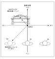
- the c function shown in FIG. 3 is exhibited. Then, in the virtual space, the process table, the time slider T, and the 3D object corresponding to the bridge (building) under construction at the time (time) specified by the time slider T are arranged.
- the time slider T is an operator (data) for designating an arbitrary time (time point) in a predetermined period of the process chart, which is arranged in the virtual space when the time slider function described above is performed.
- the time slider T is composed of a time axis indicating a predetermined period in the process table and a clock icon that can be freely moved on the time axis.
- the position of the clock icon indicates the designated time (time point). That is, the person U wearing the HMD 2 operates the controller 3 to move the clock icon of the time slider T, thereby specifying the time (time point) on the time axis in the process chart. Then, the 3D object corresponding to the bridge under construction at the designated time (time) is arranged in the virtual space. The person concerned U can visually recognize the 3D data arranged in the virtual space from a desired viewpoint at a desired standing position. In other words, for the related person U, only by moving the clock icon of the time slider T, 3D corresponding to a building (bridge) at a desired process stage among the past, present, and future within a predetermined period in the process chart. An object or the like appears on the projection space in the HMD2.
- stage confirmation result document composed of a confirmation note, a finished shape, a photograph, etc. at the time (time point) designated by the clock icon of the time slider T, It becomes possible to select from the menu of each item arranged in the virtual space.
- the function shown in FIG. 4 can be exhibited in the inspection menu.
- the a function shown in FIG. 4 may be exhibited.
- a 3D object design drawing 3D hologram
- a process chart corresponding to a completed bridge
- a time slider T corresponding to a completed bridge
- a time slider T corresponding to a time slider
- an inspection document menu are displayed in the virtual space.
- the person U wearing the HMD 2 can inspect a plurality of inspection documents while visually recognizing the plurality of inspection documents.
- the time slider T the person concerned U can exert the time slider function similarly to the function c shown in FIG.
- the related person U can set a Bookmark on a specific page of an inspection document (construction plan in the example of FIG. 4) to be confirmed later by demonstrating the b function shown in FIG. This makes it possible to return to the Bookmark page instantly.
- FIG. 5 is a block diagram illustrating an example of a hardware configuration of a server in the information processing system of FIG. 1 capable of performing various functions accompanying provision of the service will be described with reference to FIGS. 5 to 8 as appropriate.
- FIG. 5 is a block diagram illustrating an example of a hardware configuration of a server in the information processing system of FIG. 1
- the server 1 includes a CPU (Central Processing Unit) 11, a ROM (Read Only Memory) 12, a RAM (Random Access Memory) 13, a bus 14, an input / output interface 15, an input unit 16, and an output unit 17.
- the CPU 11, ROM 12 and RAM 13 are connected to each other via a bus 14.
- An input / output interface 15 is also connected to the bus 14.
- An input unit 16, an output unit 17, a storage unit 18, a communication unit 19, and a drive 20 are connected to the input / output interface 15.
- a removable medium 21 is also connected to the drive 20.
- the CPU 11 executes various processes according to a program stored in the ROM 12 or a program loaded from the storage unit 18 to the RAM 13.
- the RAM 13 appropriately stores data necessary for the CPU 11 to execute various processes.
- the input unit 16 includes a keyboard, a mouse, and the like, and inputs various information.
- the output unit 17 includes a display, a speaker, and the like, and outputs various types of information as images and sounds.
- the storage unit 18 includes a hard disk, a DRAM (Dynamic Random Access Memory), and the like, and stores various data.
- the communication unit 19 communicates with other apparatuses (HMD 2a and HMD 2b in the example of FIG. 1) via the network N including the Internet.
- a removable medium 21 made of a magnetic disk, an optical disk, a magneto-optical disk, a semiconductor memory, or the like is appropriately attached to the drive 20.
- the program read from the removable medium 21 by the drive 20 is installed in the storage unit 18 as necessary.
- the removable media 21 can also store various data stored in the storage unit 18 in the same manner as the storage unit 18.
- FIG. 6 is a block diagram showing an example of the hardware configuration of the HMD in the information processing system of FIG.
- the HMD 2 includes a CPU 31, a ROM 32, a RAM 33, a bus 34, an input / output interface 35, a display unit 36, a sensor unit 37, a storage unit 38, a communication unit 39, and a drive 40.
- the display unit 36 includes various liquid crystal displays and the like, and projects and displays a 3D object (3D monogram) of a building (bridge, etc.), an operation menu, and the like on a virtual space.
- the sensor unit 37 includes various sensors such as an inclination sensor, an acceleration sensor, and an angular velocity sensor.
- the detection information of the sensor unit 37 is used, for example, as various types of detection information related to the angle (direction) in the virtual space.
- the communication unit 39 communicates with other devices (in the example of FIG. 1, the server 1 or another controller 3) via the network N and also communicates with the controller 3 by a predetermined wireless communication method.
- the controller 3 is an input device that accepts an instruction operation by the person concerned U, for example, a menu selection, a viewpoint operation, a time (time) instruction operation with a time slider function, and the like when various processes are performed by the CPU 31 of the HMD 2.
- the controller 3 is used in the present embodiment, but it is not a particularly essential component for the information processing system.
- a motion sensor may be provided around the related person U, and various instruction operations may be performed by the various gesture operations of the related person U.
- the time slider function can be exhibited by the cooperation of the various hardware and software of the server 1, the HMD 2, and the controller 3.
- the information processing system obtains a predetermined time in the time information indicated in the process table related to the construction process as the coordinate of the time axis, and the actual object (bridge) on the construction site at the coordinate.
- 3D objects corresponding to a building) can be arranged in the virtual space, and display image data that can be viewed from a predetermined viewpoint at a predetermined position in the virtual space can be generated.
- display image generation process a series of processes until the display image data is generated and presented to the related person U (viewed by the related person U) is hereinafter referred to as “display image generation process”. Call it.
- FIG. 7 is a functional block showing an example of a functional configuration for realizing the display image generation process among the functional configurations of the server of FIG. 5 and the HMD of FIG.
- the virtual space construction unit 104, the display image generation unit 105, and the display control unit 106 function.
- An object DB 500 is provided in one area of the storage unit 18 of the server 1.
- the storage unit 18 is also provided with a DB for storing data of the stage confirmation result document, the inspection document displayed in the multi-window, and other various documents.
- the data of these various documents can also be arranged in the virtual space and included in the display image and presented to the related person U.
- FIG. 1 in the CPU 11 of the server 1
- the data of these various documents can also be arranged in the virtual space and included in the display image and presented to the related person U.
- the virtual space construction unit 104 of the server 1 constructs a virtual space for arranging 3D objects and the like of buildings (bridges).
- time slider T (FIG. 3 and the like) described above is arranged in the virtual space constructed by the virtual space construction unit 104. Therefore, the person concerned U operates the controller 3 to move the clock icon of the time slider in the virtual space (the time slider displayed on the display unit 36) on the time axis, thereby instructing a predetermined time. .
- the time information acquisition unit 100 of the server 1 acquires information (hereinafter referred to as “time information”) indicating the time instructed by the related person U through the communication unit 19.
- time information information
- each time information may be the same or different.
- a master user for example, a related person Ua
- a subordinate user for example, a related person Ub
- the time information acquisition unit 100 indicates the time designated by the controller 3 of the master user. Information is acquired as time information.
- the object placement unit 101 of the server 1 Based on the time information acquired by the time information acquisition unit 100, the object placement unit 101 of the server 1 applies an actual object (a building such as a bridge) in a state during or after construction at a specified time (time).
- the corresponding 3D object is extracted from the object DB 500 and arranged in the virtual space.
- the 3D object of the bridge in each state under construction seems to be stored in the object DB 500 in association with each time t1 to t3. Is drawn. However, actually, as will be described later with reference to FIGS.
- each part of the building is divided in units of layers, and each layer is not a single point on the time axis of time, It is stored in the object DB 500 in association with time existing in the virtual space (period having a certain width on the time axis).
- the viewpoint information acquisition unit 102 of the server 1 causes the communication unit 19 to receive the detection information of the sensor unit 37 of the HMD 2 of the person concerned U and the information of the instruction operation from the controller 3, and based on these information, Information indicating the arrangement position of the viewpoint and the direction of the viewpoint (hereinafter referred to as “viewpoint information”) is acquired.
- viewpoint information Information indicating the arrangement position of the viewpoint and the direction of the viewpoint.
- the viewpoint information may be the same or different.
- the viewpoint management unit 103 manages each piece of viewpoint information for each of a plurality of related parties U (related parties Ua and Ub in the example of FIG. 7).
- the direction of the viewpoint of a 3D object such as a bridge is not necessarily from the outside (appearance) of the 3D object to the 3D object, and may be from the inside of the object (inside the building), for example.
- the viewpoint information can have omnidirectionality.
- a 3D object obtained by reducing a large real object in a virtual space, a real-sized 3D object of a real object (building), or a 3D object having an enlarged size can be arbitrarily selected from an arbitrary position. It is possible to generate viewpoint information indicating a line of sight facing the direction.
- the related person U such as a construction worker can perform work simulation in advance in the virtual space. That is, the viewpoint information can have expandability or contractibility with respect to the visual target (3D object).
- a 3D object corresponding to a real object (a building such as a bridge) in a state during or after construction at the time indicated by the time information (time designated by the person concerned U) is arranged.
- image data seen from the viewpoint indicated by the viewpoint information is generated as display image data.
- the display control unit 106 transmits the display image data generated by the display image generation unit 105 via the communication unit 19 so as to display the display image on the display unit 36 of the HMD 2 of the person concerned U. Execute.
- FIG. 8 is a flowchart for explaining the flow of display image generation processing on the server side in FIG.
- step S1 the virtual space construction unit 104 constructs a virtual space.
- step S ⁇ b> 2 the time information acquisition unit 100 acquires time information indicating the time designated by the person concerned U.
- step S ⁇ b> 3 the viewpoint information acquisition unit 102 acquires viewpoint information indicating the position of the viewpoint in the virtual space and the direction of the viewpoint.
- step S4 the object placement unit 101 applies a real object (a building such as a bridge) in the middle of or after the construction at the designated time (time) based on the time information acquired in the process of step S2. A corresponding 3D object is placed in the virtual space.
- a real object a building such as a bridge
- step S5 the display image generation unit 105 displays, in the virtual space in which the 3D object is arranged in the process of step S4, image data that can be seen from the viewpoint indicated by the viewpoint information acquired in the process of step S3. Generate as data.
- step S ⁇ b> 6 the display control unit 106 transmits the display image data generated in step S ⁇ b> 5 via the communication unit 19, thereby presenting the display image to the related person U.
- step S7 the server 1 determines whether or not there is an instruction to end the process.
- An instruction to end the process is not particularly limited, but for example, it can be adopted that an end instruction is transmitted from the HMD 2. If such an end instruction has not been transmitted from the HMD 2, it is determined NO in step S7, the process returns to step S2, and the subsequent processes are repeated. On the other hand, when an end instruction is transmitted from the HMD 2, it is determined as YES in Step S7, and the display image generation process ends.
- time information for example, a predetermined time
- a predetermined 3D object at the construction site for example, a scene that the person concerned U can visually recognize from a predetermined standing position and angle at the predetermined time
- time information for example, a predetermined period
- the layer is a minimum unit constituting various information that can be arranged in a virtual space such as “3D object (including 3D hologram)”, “document data”, and the like, for example, an iron bridge portion of a bridge.
- FIG. 9 is a diagram showing various types of information stored in the server / HMD object DB 500 of FIG. 7, and is a diagram showing an example different from FIG.
- the layers b1 to b5 are associated with time information (predetermined period) and the information is stored in the object DB 500.
- the predetermined period indicates, for example, a certain period from time t1 to time t5, and does not indicate one time point of time t1, for example.
- Layer b1 is, for example, one of the legs of a bridge that is scheduled for construction.
- a period from time t1 to time t5 is designated. That is, the layer b1 is displayed on the virtual space as a part of the bridge scheduled to be constructed at the time t1, and is still displayed on the virtual space at the time t5.
- the layer b5 is, for example, a “scaffold” used by workers at a construction site. In the layer b5, a period from time t2 to time t4 is designated.
- the layer b5 is displayed on the virtual space as a scaffold for construction at time t2, and is not displayed at time t4, that is, when the bridge is completed. This is because in the actual construction site, the scaffold is completely removed at the completion stage of the bridge.
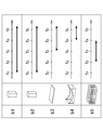
- FIG. 10 is a diagram for explaining the relationship with the layers displayed in each period.
- the image displayed on the person concerned U is displayed in each period from the time t1 to the time t2, the time t2 to the time t3, the time t3 to the time t4, and the time t4 to the time t5.
- the layer b1 and the layer b2 are displayed independently. That is, in the construction process from the time t1 to the time t2, only the leg portion of the bridge is scheduled to be constructed.
- the person concerned U wants to confirm the construction status during the period from the time t1 to the time t2, he can select and display an image of the construction site during the period. In this regard, as described above with reference to FIG.
- the layer b5 (building scaffold) is normally used only during construction and is normally removed when completed.
- the layer b5 is displayed only in the period from time t2 to time t3 and from time t3 to time t4. That is, the layer b5 is installed at the time t2, and is removed at the time t4.
- the person concerned U can, for example, perform the following using the time slider function described above. It becomes. That is, since the person concerned U can visually recognize the 3D object to be constructed on the “designated arbitrary time axis”, it can freely go back and forth between the past and the future (time slide). Further, for example, the related person U can slide the vertical time axis (time slider) on the horizontal time axis (time line), and the 3D object scheduled to be constructed on an arbitrary time axis (for example, period). The image (or the image of the construction site) can be visually recognized.
- the difference between the prior art and the time slider function according to the first and second embodiments described above is as follows. That is, when displaying an image of a 3D object or the like to be constructed, conventionally, data at a predetermined time (time) is usually processed and displayed. On the other hand, in the time slider function, the time axis of each layer can be processed and displayed so as to be a line (period).
- each layer can be defined as only one time point (for example, the latest time point) as a time attribute, whereas a time axis (for example, a period) can be defined as a time attribute for each layer. .
- a time axis for example, a period
- 3D data on a specified arbitrary time axis is constructed without creating 3D data for each specified arbitrary time point. Can do.
- Each layer constructed as in (2) can be displayed on a display medium (for example, the display unit 36 in FIG. 6).
- the inspection function is employed as an example of a basic function that can be realized by the information processing system.
- a “TOP menu” for transitioning to each menu.
- the following five menus are prepared as menus that can be changed from the “TOP menu”. That is, a plan menu, a design change menu, an inspection menu, a maintenance menu, and a communication menu are prepared.
- the information processing system capable of exhibiting the time slider function has been described.
- the function that can be exhibited by the information processing system to which the present invention is applied is not limited thereto. That is, in the above-described embodiment, the direction of change in the virtual space is the direction of the time axis, but is not particularly limited thereto, and an arbitrary axis direction can be adopted.
- an axis indicating each company hereinafter referred to as “company axis” can be defined, and each company can correspond to each coordinate of the company axis.
- the person U can arbitrarily designate the coordinates of the company axis, he can visually recognize a 3D object of a building such as a bridge constructed by the company indicated by the designated coordinates.
- a company in charge of construction of a building such as a bridge can be determined at a competition of multiple companies, it is possible to compare the buildings such as a bridge designed by each of the companies participating in the competition.
- the number of axes that can be designated by the person concerned U is not limited to one, and a plurality of axes can be designated. For example, if two designations of a company axis and a time axis are possible, the person concerned U can compare each state during construction of a plurality of companies for each construction process.
- an information processing apparatus to which the present invention is applied only needs to have the following configuration, and can take various embodiments. That is, an information processing apparatus to which the present invention is applied A 3D object corresponding to a real object (for example, a bridge or the like) whose state changes in a direction of at least one dimension (for example, a time axis direction or a company axis direction) among n dimensions (n is an integer value of 2 or more).
- Arrangement means for example, the object arrangement unit 101 in FIG. 7) arranged in a three-dimensional virtual space; Among the n dimensions, coordinate acquisition means (for example, the time information acquisition unit 100 in FIG.
- Image generation means for generating data of an image that can be viewed from a predetermined viewpoint in the virtual space in which the 3D object corresponding to the real object in the coordinate in the acquired dimension is arranged by the arrangement means (for example, the display image generation unit 105) in FIG.
- An information processing apparatus comprising: Thereby, the person concerned U can be expected to understand the construction process intuitively even if he is not familiar with the construction business.
- the inspection function is employed as an example of a basic function that can be realized by the information processing system according to the embodiment of the present invention.
- basic functions that can be realized by the information processing system according to the embodiment of the present invention include, for example, “TOP menu”, “plan menu”, “design change menu”, “ A "communication menu”, a "maintenance menu”, etc. can also be employed.
- TOP menu “plan menu”
- design change menu “ A "communication menu”
- a "maintenance menu” etc.
- FIG. 11 is a diagram illustrating an example of basic functions that can be realized by the information processing system of FIG. 1. Specifically, the basic functions that can be realized by the information processing system according to the embodiment of the present invention It is a figure which shows an example when the "TOP menu" shown in FIG. 2 is employ
- the “TOP menu” refers to an initial screen of an object (also referred to as a 3D model) displayed in the virtual space, for example.
- the situation a shown in FIG. 11 includes a party U who is a beneficiary of this service and a building (for example, a bridge) to be constructed. That is, the related person Ub can visually recognize the building to be constructed as a 3D object in the virtual space. In addition to the 3D object of the building to be constructed, the related person Ub may project a forklift used for construction, for example, as a support object that is not an inspection object.
- a forklift used for construction, for example, as a support object that is not an inspection object.
- FIG. 11 an example in which the person concerned Ub moves to the left and right of the bridge is shown. That is, the person concerned Ub can visually recognize the building to be constructed from various distances and angles by changing the standing position that he / she moves and visually recognizes.
- the related person Ub when the person concerned Ub wants to move the construction site, more precisely, when he wants to move in the virtual space corresponding to the construction site, the related person Ub actually moves, so that the sensor unit 37 of the HMD 2b shown in FIG. However, it is possible to detect the information and change the standing position in the virtual space.
- the related person Ub may move to a position where the building scheduled for construction can be easily viewed without moving.
- the person concerned Ub moves the building itself to an arbitrary place without moving, in addition to moving himself and changing the standing position. By displaying them, it is possible to visually confirm the buildings at various work stages from various distances and angles.
- the person concerned Ub operates the controller 3b to designate the construction process, and at the desired standing position, the scenery of the construction site including the construction planned to be seen when facing the desired direction (part A photograph showing the scenery) can be visually recognized.
- the related person Ub does not necessarily need to determine the “standing position” or “the direction of the line of sight (predetermined direction)” using the controller 3b.
- the sensor unit 37 of the HMD 2b may detect the movement of the related person Ub and determine the “standing position” or “the direction of the line of sight (predetermined direction)” of the related person Ub.
- FIG. 11 an example is shown in which a plurality of parties visually recognize a building that is scheduled to be constructed.
- the related person Ua and the related person Ub can visually recognize the same building planned for construction.
- the person concerned Ua and the person concerned Ub do not need to select a building scheduled to be constructed on the same time axis. That is, each of the related person Ua and the related person Ub may be able to select and visually recognize a building to be constructed at a different work stage.
- the related person Ua and the related person Ub do not need to select the same building scheduled for construction. That is, for example, the person concerned Ua may visually recognize other buildings (such as other bridges) scheduled to be built.
- FIG. 12 and 13 are diagrams illustrating examples of basic functions that can be realized by the information processing system in FIG. 1, and specifically, the basics that can be realized by the information processing system according to the embodiment of the present invention. It is a figure which shows an example when the "plan menu" is employ
- the a function shown in FIG. 12 shows an example of a display image when an image related to the time slider T function is displayed for a related person (for example, a related person U) not shown. That is, a related person (for example, a related person U) (not shown) can confirm and select the construction status from the time slider function. Specifically, for example, in the example of the a function shown in FIG. 12, the construction date T of “November 1” is selected by a person U (not shown). Then, the person U (not shown) can confirm the building to be constructed corresponding to the construction stage selected by the time slider T, the process schedule, the construction plan, and the construction plan document related thereto. In the example of the a function shown in FIG.
- the status of the building scheduled to be constructed on the time slider T of “November 1” is displayed at the top of the a function shown in FIG.
- the b function shown in FIG. 12 an example in which a person U (not shown) visually recognizes the construction status of the building scheduled for construction on the time slider T on “November 1”. It is shown. That is, the person U (not shown) can determine his / her standing position in the virtual space by operating the humanoid icon P displayed in the image, for example.
- the building to be constructed can be easily confirmed.
- the c function shown in FIG. 12 there is a work experience around the reinforcing bars and a confirmation of the work in the sheet pile.
- the related person Ub can finely adjust the display position on the 3D object while displaying the actual 3D object.
- the e function shown in FIG. 13 it is possible to make the contact between a real-size 3D object and a real person visible by highlighting or sound.
- a construction machine or the like of a full size can be arranged to simulate the construction work.
- the related person U can use the above-described various functions to find in advance problems that are not noticed unless the construction is actually started. Specifically, for example, the person concerned U cannot work without his arms passing through the rebar mesh by visually examining a full-scale bridge before starting construction work or the like. Problems that may occur during actual construction work can be revealed in advance. In other words, because the person concerned U can easily understand the construction process more intuitively by using the various functions described above, even if the person concerned U is not familiar with the construction work, It makes it easier to request corrections to the construction process required before. Therefore, cost reduction, construction period shortening, safety improvement, etc. can be expected in construction work, and as a result, improvement in customer satisfaction is expected.
- 14 and 15 will be described. 14 and 15 are diagrams illustrating an example of a design change menu among functions that can be realized by the information processing system of FIG.
- FIG. 14 and 15 are diagrams illustrating examples of basic functions that can be realized by the information processing system according to the embodiment of the present invention. Specifically, the information processing system according to the embodiment of the present invention is illustrated. It is a figure which shows an example when the "design change menu" is employ
- the situation a shown in FIG. 14 shows a situation in which the concerned person Ua and the concerned person Ub are discussing while visually recognizing the 3D object scheduled to be constructed in the virtual space. Specifically, in the situation a shown in FIG. 14, the related person Ua and the related person Ub can visually recognize the same 3D object from their desired “standing position” and “angle”.
- a person concerned U (orderer, consultant, contractor, etc.) of the construction business predicts a problem that may occur in each step of the construction work while referring to the same 3D object (and related data), It is possible to examine the suitability of each step of the construction work of the 3D object while discussing “whether there is a design change” and in some cases “how to change”. Further, for example, when a plurality of construction work process patterns are assumed in advance, it is also possible to confirm the result of simulating costs, schedules, safety, and the like for each construction work process. Next, the situation b shown in FIG. 14 shows an example in which the 3D object is enlarged or reduced in the virtual space.
- a person U creates a 3D object to be constructed in the virtual space, for example, 1/400 times, 1/200 times, 1/100 times, 1/50 times, 1/25 times, 2 times. It is also possible to visually recognize a 3D object that has been enlarged or reduced at the same magnification. Specifically, for example, in the case of a large building, a geological survey or the like is performed at the time of designing, but it may be found that the construction is different from the assumption at the time of construction. These functions are also sufficient, for example, at a construction facilitation promotion meeting where parties involved in the construction business (orderers, consultants, contractors, etc.) meet and exchange opinions for smooth communication. Can contribute.
- the a function shown in FIG. 15 and the b function shown in FIG. 15 show an example when the design is changed.
- the 3D object can be updated based on the new drawing data.
- the design drawing of the changed part can be identified by highlighting or the like.
- the person U can confirm the costs before and after the above-described design change, the construction period, and the like. Further, the person U (not shown) may be able to confirm, for example, the schedule and safety in addition to the cost and the construction period.
- the U concerned parties orderers, consultants, contractors, etc.
- productivity can be expected to improve.
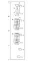
- FIG. 16 is a diagram illustrating an example of basic functions that can be realized by the information processing system of FIG. 1, and specifically, basic functions that can be realized by the information processing system according to an embodiment of the present invention. It is a figure which shows an example when a "maintenance menu" is employ
- the inspection data that can be referred to by a maintenance person is, for example, a check list, a photograph, a drone video, 3D scan data, or the like. That is, in the example of the situation a shown in FIG. 16, the maintenance person refers to the checklist used in the maintenance performed around July 2016, and what kind of maintenance was performed in the maintenance. You can make decisions about your own maintenance. In addition, in the situation b shown in FIG. 16, around September 2015 is selected as the date to be checked.
- the data that can be referred to by the maintenance staff at this time includes, for example, a stage confirmation result document (data) composed of a confirmation note, a completed shape, a photograph, and the like. That is, in the example of the situation b shown in FIG. 16, the person in charge of maintenance refers to various data (confirmation document, completed shape, photograph, etc.) at the time of construction around September 2015, and makes a judgment about his / her own maintenance. Can be defeated.
- a person in charge of maintenance can realize accurate maintenance (maintenance management, diagnosis management), so that it can be expected that quality improvement as a whole will be connected.
- maintenance personnel can perform maintenance (maintenance management, diagnostic management) from a remote location without going to the site without providing scaffolding etc. on the actual object to be constructed. Since it can handle many sites, it can be expected to improve productivity.
- FIG. 17 is a diagram illustrating an example of basic functions that can be realized by the information processing system of FIG. 1. Specifically, the basic functions that can be realized by the information processing system according to an embodiment of the present invention are illustrated. It is a figure which shows an example when a "communication menu" is employ
- the related person Ua and the related person Ub exist in places that are separated from each other by distance.
- the related person Ua and the related person Ub can visually recognize the same 3D object at each place even when they are away from each other.
- the related person Ua for example, a sales representative who is away from home
- the related person Ub for example, a field supervisor at the work site
- such a plurality of parties to have a conversation while instructing a specific part of the 3D object being viewed by marking or the like while looking at the design drawing or the like at a remote place.
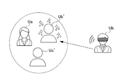
- the communication menu examines the construction status and construction policy of the person concerned Ua and the person concerned Ub who are using the HMD2 while visually observing the 3D objects arranged in the virtual space in common. It is used when doing so. More specifically, for example, it is assumed that the related person Ua and the related person Ub exist within a range where they cannot communicate directly with each other. In such a case, for example, it is possible to visually recognize the 3D object by using each HMD 2. However, for example, when the related person Ua and the related person Ub want to discuss the situation of one area in the object, it is necessary to accurately grasp which part of the 3D object the other party is trying to discuss. For example, it is difficult to discuss.
- the communication menu in the present embodiment employs an avatar arrangement function as a function for each party to smoothly communicate.
- This avatar arrangement function is one of the most important functions among the functions related to the communication menu.
- a humanoid object corresponding to the position or angle in the virtual space of another related person for example, the related person Ub
- avatar a humanoid object corresponding to the position or angle in the virtual space of another related person (for example, the related person Ub) (hereinafter referred to as “avatar”). Is placed in the virtual space.
- the related person Ua can visually grasp the position and angle of the related person Ub in the virtual space by this avatar function, so that the related person Ub can communicate with the related person Ub more smoothly.
- a specific method and process for the HMD 2 to arrange the avatar in the virtual space will be described later with reference to FIG.
- the avatar arrangement process in which the HMD 2 is arranged in the virtual space and a series of processes displayed on the display unit 36 are collectively referred to as an avatar arrangement process is also described with reference to FIG. It will be described later.
- FIG. 18 is a functional block showing an example of the functional configuration of the function related to the “communication menu” described in FIG. 17 and the like out of the functional configuration of the HMD in FIG.
- the hardware configuration of the HMD in FIG. 18 is obtained by adding a voice input / output unit 42 to the hardware configuration in FIG. 6 described above.
- the audio input / output unit 42 is connected to the input / output interface 35 of FIG.
- the audio input / output unit 42 includes a microphone and headphones (headset).
- the microphone receives external sound, converts it into an electrical signal (hereinafter, such signal is referred to as “voice information”), and supplies the converted signal to the processing unit 303 of the CPU 31.
- the headphones convert the sound information supplied from the processing unit 303 of the CPU 31 into sound using a sounding body (speaker or the like) close to the ears (eardrum) of the related person Ua or the related person Ub.
- a display control unit 301 in the CPU 31 of the HMD 2, a display control unit 301, a time information acquisition unit 302, and a processing unit 303 function.
- a three-dimensional data DB 401 In the storage unit 38, a three-dimensional data DB 401, a document data DB 402, and a time attribute definition DB 403 are provided.
- the processing unit 303 performs various processes related to images to be displayed on the display unit 36 and various processes related to audio to be input to and output from the audio input / output unit 42 via the display control unit 301.
- the voice uttered by the related person Ua is input at the voice input / output unit 42, converted into voice information, and supplied to the processing unit 303.
- the processing unit 303 executes control processing for transmitting the audio information from the communication unit 39 to the server 1 via the network N.
- the voice information is transmitted from the server 1 to the HMD 2 attached to the related person Ub via the network N.
- the related person Ub can listen to the sound corresponding to the sound information output from the HMD 2, that is, the sound emitted from the related person Ua.
- the voice uttered by the related person Ub is input to the HMD 2 attached to the related person Ub, converted into sound information, output, and transmitted to the server 1 via the network N.
- the voice information is further transmitted from the server 1 via the network N to the HMD 2 attached to the related person Ua.
- the processing unit 303 causes the communication unit 39 to receive the audio information, performs various processes, and supplies the audio information to the audio input / output unit 42.
- the related person Ua can listen to the sound corresponding to the sound information output from the sound input / output unit 42, that is, the sound emitted from the related person Ub.
- the process performed on the audio information by the processing unit 303 is not particularly limited, and various kinds of processes can be employed.
- the following processing is executed by the processing unit 303.
- the avatar of the conversation partner for example, the related person Ub from the viewpoint of the related person Ua
- the processing unit 303 is executed, the avatar of the conversation partner (for example, the related person Ub from the viewpoint of the related person Ua) is displayed in the virtual space. It is visually recognized by a person wearing the HMD 2 (for example, the related person Ua) so as to be arranged at a position corresponding to a predetermined place in the space. That is, an image that can be viewed as such is displayed on the display unit 36.
- the processing unit 303 assumes that the sound generation source is the position where the avatar is present, and the sound generation source and the sound transmission destination (person wearing the HMD2, for example, the related person Ua).
- the processing for adjusting the balance of the audio output based on the positional relationship is performed on the audio information.
- a voice spoken by the avatar is output from the right speaker of the voice input / output unit 42 and can be heard from the right ear of the voice transmission destination.
- the process relating to the image is a process corresponding to the display image generation process described with reference to FIG.
- the display image generation processing has been described as being executed on the server 1 side, it is not necessarily required to be executed entirely on the server 1 side. Therefore, here, the following description will be given on the assumption that the display image generation processing is executed on the HMD 2 side. That is, as processing relating to a display image, for example, the following processing based on the above-described display image generation processing is executed by the processing unit 303.
- the three-dimensional data DB 401 corresponds to the object DB 500 in FIG.
- the 3D object is divided into layers and associated with time information (predetermined period).
- the document data DB 402 stores stage confirmation result documents, inspection documents displayed in a multi-window, and various other document data (hereinafter collectively referred to as “document data”).
- the time attribute definition DB 403 stores time attribute definition information including correspondence between each layer of the 3D object and time information.
- the storage unit 38 stores 3D objects (3D models) in the 3D data DB 401, document data (2D) in the document data DB 402, and time attribute definition (4D) information in the time attribute definition DB 403, respectively.
- the minimum model unit is a layer.
- the file unit is a layer.
- a time axis (period) represented by a start time and an end time is defined as a time attribute.
- the contents of the definition for each layer are used as time attribute definition information.
- the processing unit 303 is information on each layer associated with an arbitrary time axis (period) or time (for example, as of 10:10 on June 15, 2015) specified by the time information acquisition unit 302 described later. Are obtained by searching the three-dimensional data DB 401 and the time attribute definition DB 403.
- the processing unit 303 generates a 3D object by stacking these layers.
- the processing unit 303 constructs a virtual space and arranges the 3D object described above.
- the processing unit 303 arranges various kinds of information such as the above-described time slider T in addition to the 3D object in the virtual space.
- the processing unit 303 further arranges the avatar of the conversation partner (for example, the related person Ub in the position of the related person Ua) at an existing position in the virtual space (a position corresponding to a predetermined place in the real space). Specifically, for example, the processing unit 303 executes the following process in order to place an avatar in a virtual space under a remote environment. That is, in the HMD 2 of the conversation partner such as the related person Ub, information indicating the existing position and information for specifying the viewpoint at the existing position, that is, the position from the reference point, the height from the reference point, the neck Information such as tilt and line of sight is acquired as avatar information and transmitted to the server 1.
- the reference point is a reference point on the virtual space serving as a reference for grasping the position and information of the arrangement of the avatar and the 3D object in the virtual space of the HMD 2 worn by the person concerned U.
- the processing unit 303 acquires the information via the communication unit 39. Based on this avatar information, the processing unit 303 arranges the avatar of the conversation partner such as the related person Ub in the virtual space.
- the processing unit 303 since the virtual space is also constructed in the conversation partner HMD2 such as the related person Ub, it is necessary to arrange the avatar of the person (the related person Ua, etc.) wearing the HMD2 in the virtual space. is there. Therefore, the processing unit 303 generates avatar information of a person (related person Ua or the like) wearing the HMD 2 based on information from the sensor unit 37 and transmits the avatar information to the server 1 via the communication unit 39.
- the processing unit 303 can execute various processes including an avatar arrangement process for arranging an avatar on the virtual space related to the communication menu.
- Ua and Ub) can communicate more smoothly.
- the time information acquisition unit 302 acquires information on an arbitrary time axis (time) or time (hereinafter referred to as “designated time information”) via the communication unit 39.
- the designated time information may be acquired from, for example, the server 1 or another HMD 2 in addition to an operation by the controller 3 (not shown).
- the designated time information from which the related person Ua and the related person Ub are acquired may or may not be the same.
- a master user for example, the related person Ua
- a subordinate user for example, the related person Ub
- the designated time information may also be acquired by the subordinate user's HMD2.
- the display control unit 301 executes control for displaying three-dimensional data (for example, an object), two-dimensional data (for example, document data), an avatar, and the like on the display unit 36.
- the display control unit 301 may execute not only the display control for the avatar displayed on the display unit 36 but also the following display control. Specifically, for example, the display control unit 301 may execute control for blinking and displaying an avatar corresponding to a person who is emitting a voice.
- the display control unit 301 may execute control for displaying the names of the parties concerned over the avatars corresponding to the respective parties.
- the display control unit 301 may perform control to move the avatar's neck in conjunction with the neck movements of the parties involved.
- FIG. 19 is a diagram showing conditions for transmitting / receiving various information and arranging avatars for realizing the “communication menu” of FIG.
- “local” means a case where the receiver and the sender are within a range where they can communicate directly. Specifically, for example, the receiver and the sender are in a meeting using the HMD 2 in the same conference room.
- “Remote” refers to a case where the receiver and the sender do not exist within a range where direct communication is possible. Specifically, for example, this is a case where a conference is performed using HMD2 in remote places (Tokyo and Osaka, etc.).
- a sender means the person who transmits the avatar information etc. which were acquired by the sensor part 37 grade
- a receiver means the person who acquires the avatar information etc. which were received by the sender.
- “user relationship sender-recipient”, “position”, “height”, “speech”, “operation”, “avatar display” Is displayed.
- the topmost “user relationship sender-recipient” indicates the relationship between the sender and the receiver.
- the left side indicates a sender
- the right side indicates a receiver
- “local-local” is a case where both the sender and the receiver are in a local environment.
- the “position” at the top is information regarding the position from the reference point acquired by the sensor unit 37 of the HMD 2 worn by the sender.
- the “height” at the top is information regarding the height from the reference point acquired by the sensor unit 37 of the HMD 2 worn by the sender.
- the uppermost “voice” is voice information acquired by the voice input / output unit 42 of the HMD 2 worn by the sender.
- the uppermost “operation” is, for example, information (hereinafter referred to as “operation information”) regarding operation of time information for placing a 3D object using a time slider function by the controller 3 on the sender side. is there.
- the uppermost “avatar display” is to display the avatar on the sender side to the receiver, that is, to arrange the avatar.
- “ ⁇ ” is “position”, “height”, “operation”, the sender sends the above information, “voice”, “avatar display”, voice output, avatar It means to arrange.
- “X” means “send”, “height”, “operation” means that the sender does not send the above information
- “voice”, “avatar display” means voice output and avatar arrangement. It means not. (1) About “local-local” case. If both one sender and one or more recipients exist in the local environment, the “Position”, “Height”, and “Operation” columns are “O”, and the sender Information on the position and height from the reference point and operation information are transmitted. On the other hand, the columns of “voice” and “avatar display” are “x”, and output of voice information and arrangement of avatars are not performed for the receiver.
- the sender performs transmission of information regarding the position and height from the reference point, height information, audio information, operation information, and arrangement of the avatar to the receiver.
- the output of the 3D object and the voice of the sender and the avatar are arranged on the HMD 2 worn by the receiver.
- (3) About “Local-Remote” case. Even if one sender exists in the local environment and one or more recipients exist in the remote environment, “position”, “height”, “voice”, “operation” and “avatar display” Is “ ⁇ ”. That is, as in (2) above, the sender transmits the above-described various information to the receiver, and arranges the avatar.
- the output of the 3D object and the voice of the sender and the avatar are arranged on the HMD 2 worn by the receiver.
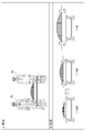
- FIG. 20 is a diagram illustrating an arrangement of 3D objects in the same space according to an existing technology.
- the HMD2 worn by the related person Ua is described as HMD2-a
- the HMD2 worn by the related person Ub is described as HMD2-b.
- the related person Ua exists in a predetermined space (local environment or remote environment) such as an office of the Tokyo head office.
- the related person Ua can visually recognize the 3D object on the virtual space displayed on the display unit 36 of the HMD2-a worn by the related person Ua in the predetermined space.
- the reference point A in the situation a shown in FIG. 20 is on the virtual space serving as a reference for grasping the position and information of the arrangement of the avatar and 3D object in the virtual space of the HMD2-a worn by the person concerned Ua. This is the point of reference.
- the reference point A is fixed in the virtual space by setting the reference point A by the person concerned Ua.
- the 3D object is centered on the reference point A.
- the setting method of the reference point A is not particularly limited.
- the related person Ua uses the controller 3 or the like (not shown) to place an arbitrary position where the 3D object is desired to be arranged in the virtual space. May be set as a reference point.
- an arbitrary position can be set as a reference point regardless of the narrowness and area of the room. Become.
- the related person Ub is in a predetermined space (hereinafter referred to as “remote location”) different from the related person Ua, such as an office of the Osaka branch office.
- remote location a predetermined space
- the person concerned Ub can visually recognize the 3D object on the virtual space displayed on the display unit 36 of the HMD2-b worn by the person concerned Ub, for example, at the above-mentioned remote place.
- the reference point A ′ grasps the position and information of the arrangement of the avatar and 3D object in the virtual space of the HMD2-b worn by the person concerned Ub.
- the reference point A ′ is fixed in the virtual space. Therefore, in the situation b shown in FIG. 20, in the existing technology, the reference point A ′ is the center. 3D objects can be placed.
- the setting method of the reference point A ′ can be set by the person concerned Ub in the same manner as the setting method of the reference point A. Thereby, when the person concerned Ub visually recognizes the 3D object, an arbitrary position can be set as a reference point regardless of the narrowness and area of the room. Become.
- the related person Ua and the related person Ub exist in the same predetermined space.
- the 3D object can be visually recognized in the virtual space displayed on the display unit 36 of the HMD 2-a and 2-b worn by the concerned person Ua and the concerned person Ub, respectively.
- the HMD2-a worn by the related person Ua or the HMD2-b worn by the related person Ub has the same position as the reference point A set by the related person Ua and the reference point A ′ set by the related person Ub.
- the reference point A set by the person concerned Ua and the reference point A ′ set by the person concerned Ub are set at the same position, so that the direction and distance from the reference point A can be changed.
- the same 3D object is placed in the virtual space of the HMDs 2-a and 2-b worn by the concerned person Ua and the concerned person Ub, respectively.
- the object can be visually recognized from the front, and the person concerned Ub can visually recognize the 3D object from the back.
- the related person Ua and the related person Ub can arrange the same 3D object by sharing the same virtual space and can communicate with each other.
- FIG. 21 is a diagram relating to movement of parties in the same space using existing technology.
- the related parties Ua and the related parties Ub move by themselves.
- the same 3D object can be visually recognized in the same virtual space described above.
- the related person Ua and the related person Ub move, since the set reference point A is fixed, the 3D object is arranged based on the fixed reference point A. Therefore, the related person Ua and the related person Ub can visually recognize the same 3D object and the like at various positions and angles in the same virtual space as they move.
- FIG. 22 is a diagram relating to movement of parties in another space using remote communication.
- Remote communication is a conversation in which a plurality of persons U are located at a distance from each other by placing 3D objects, avatars, etc. in the same virtual space using the HMD 2 via the server 1. It is to hold a meeting.
- many related parties U are involved in construction work. Therefore, it is very important that a large number of parties U share the recognition of work processes and the like. Therefore, using the remote communication described above, multiple parties U can simultaneously refer to and operate the same 3D object, etc. in the virtual space, and in addition to detailed meetings for each process, confirmation of on-site safety, etc. Can be done.
- the related person Ua can hold a conversation, a meeting, etc.
- the related person Ua can make communication closer to reality by arranging the related person Ub existing in the remote place as the avatar Ub ′ in the virtual space.
- the related person Ua exists in an office of the Tokyo head office, and the related person Ub exists in a remote place such as an office of the Osaka branch office. Therefore, the related person Ua visually recognizes the 3D object, the related person Ub existing in the remote place as an avatar Ub ′ on the virtual space of the HMD2-a worn by the related person Ua.
- the 3D object visually recognized by the related person Ua and the avatar Ub ′ of the related person Ub will be described.
- the related person Ua can visually recognize the 3D object displayed on the virtual space while moving and the avatar Ub ′ of the related person Ub.
- the HMD 2-b worn by the related person Ub acquires the avatar information (position and angle from the reference point A) of the related person Ub corresponding to the movement of the related person Ub via the sensor unit 37. Then, the acquired avatar information of the related person Ub is transmitted to the HMD 2-a worn by the related person Ua.
- the HMD2-a worn by the related person Ua acquires the avatar information of the related person Ub, arranges (or rearranges) the avatar Ub ′ corresponding to the related person Ub based on the information, and displays the display unit. 36.
- the related person Ua and the related person Ub have the avatars Ua ′ and Ub reflecting the positional relationship from the 3D object in the respective HMDs 2-a and 2-b worn by themselves.
- ′ Can be visually recognized, so that even if the parties Ua and Ub exist in separate spaces where direct communication is not possible, the network N can be used in the same virtual space. Therefore, expressions linked to each other are possible. The same applies to FIG.
- FIG. 23 is a diagram relating to movement of parties in another space using remote communication, and is a diagram illustrating an example different from FIG.
- the related person Ua exists in the office of the Tokyo head office, and the related person Ub exists in a remote place such as the office of the Osaka branch office. Therefore, the related person Ub visually recognizes the related person Ua existing in the 3D object, the office of the Tokyo head office, etc. as the avatar Ua ′ in the virtual space of the HMD2-b worn by the related person Ub.
- the 3D object visually recognized by the related person Ub and the avatar Ua ′ of the related person Ua will be described. Specifically, for example, similarly to FIG.
- the related person Ub can visually recognize the 3D object displayed on the virtual space while moving and the avatar Ua ′ of the related person Ua. Further, the HMD 2-a worn by the related person Ua acquires the avatar information of the related person Ua corresponding to the movement of the related person Ua via the sensor unit 37. Then, the acquired avatar information is transmitted to the HMD 2-b worn by the related person Ub. The HMD2-b worn by the related person Ub acquires the avatar information of the related person Ua, arranges (or rearranges) the avatar Ua ′ corresponding to the related person Ua based on the information, and displays the display unit. 36 can be displayed.
- FIG. 24 is a diagram related to the arrangement of avatars by remote communication in FIGS. 22 and 23.
- the related person U will be described by the related person Ua, the related person Ub, and the related person Uc.
- the HMD2 worn by the related person Ua will be described as HMD2-a, the HMD2 worn by the related person Ub as HMD2-b, and the HMD2 worn by the related person Uc as HMD2-c.
- the server 1 (not shown in FIG. 24) communicates with each of the HMD 2-a, HMD 2-b, and HMD 2-c, and receives various information.
- each of HMD2-a, HMD2-b, and HMD2-c has information to be exchanged with each other such as information indicating its own position, avatar information, and voice information (hereinafter referred to as “exchange information”). It always transmits and receives via the server 1. Therefore, each of HMD2-a, HMD2-b, and HMD2-c performs the following processing based on the exchange information.
- each of the related person Ua, the related person Ub, and the related person Uc can recognize the existence of an actual person. Therefore, each of the HMDs 2-a to 2-c attached to each of the related parties Ua to Uc does not output a voice and can prevent an avatar from being placed in the virtual space. The arrangement of avatars in the virtual space and the presence or absence of audio output will be described.
- each of the HMDs 2-a to 2-c attached to each of the parties Ua to Uc has their own current position using GPS (Global Positioning System) or the like (for example, the above-mentioned It is possible to provide a function for notifying information on the Tokyo head office. Therefore, for example, the HMD 2-a worn by the related person Ua uses the avatar information, voice information, and the like as exchange information in addition to the information on the current position described above, via the server 1 to each of the HMDs 2-b and 2-c. Send to. Similarly, the HMD 2-b transmits the exchange information to each of the HMDs 2-a and 2-c via the server 1.
- GPS Global Positioning System
- the HMD 2-c transmits the exchange information to each of the HMDs 2-a and 2-b via the server 1.
- the server 1 can acquire the exchange information of each of the HMDs 2-a to 2-c, so that, for example, based on the information on the location of each of the HMDs 2-a to 2-c, It is determined that the related person Ua, the related person Ub, and the related person Uc exist within a certain range. That is, the server 1 determines, for example, the case of (1) “local-local” shown in FIG. Therefore, the HMD 2-a worn by the related person Ua receives the exchange information (voice information, avatar information, etc.) from the HMD 2-b and 2-c, but the voices of the related person Ub and the related person Uc.
- the server 1 determines, for example, the case of (1) “local-local” shown in FIG. Therefore, the HMD 2-a worn by the related person Ua receives the exchange information (voice information, avatar information, etc.) from the HMD 2-b and 2-c, but the voices of the related
- the voice output is not performed, and the avatar Ua ′ of the related person Ua and the avatar Uc ′ of the related person Uc are not arranged.
- the 3D object and the like are arranged in the virtual space displayed on the display unit 36 of the HMD 2-b worn by the related person Ub, but the avatar Ua ′ of the related person Ua and the avatar Uc ′ of the related person Uc are The voices of the related person Ua and the related person Uc are not output from the voice input / output unit 42.
- the HMD 2-c worn by the related person Uc receives the exchange information (voice information, avatar information, etc.) from the HMD 2-a and 2-b, but each of the related person Ua and the related person Ub.
- the related person Ua and the related person Uc exist in the same space such as the office of the Tokyo head office, and the related person Ub exists in another space such as the office of the Osaka branch office. Shall exist.
- the related person Ua and the related person Uc can recognize the existence of the actual related person Ua and the related person Uc.
- the related person Ua and the related person Uc cannot recognize the existence of the actual related person Ub. Therefore, the HMD2-a and HMD2-c worn by the related person Ua and the related person Uc can output the voice of the related person Ub, and can place the avatar Ub ′ of the related person Ub in the virtual space. it can.
- each of the HMD2-a and HMD2-c worn by the related person Ua and the related person Uc does not output the voices of the related person Ua and the related person Uc, and the avatar Ua of the related person Ua is displayed in the virtual space. 'And the avatar Uc' of the related person Uc can be prevented from being arranged.
- the arrangement of avatars in the virtual space and the presence or absence of audio output will be described.
- the related person Ua and the HMD 2-a and the HMD 2-c worn by the related person Uc transmit the avatar information, voice information, and the like as exchange information to the HMD 2-b via the server 1 in addition to the current position information. To do.
- the HMD 2-b transmits the exchange information to each of the HMDs 2-a and 2-c via the server 1.
- exchange information is also transmitted between the HMD 2-a and the HMD 2-c via the server 1.
- the server 1 can acquire the exchange information of each of the HMDs 2-a to 2-c, so that, for example, based on the information on the location of each of the HMDs 2-a to 2-c, It is determined that the related person Ua and the related person Uc exist within a certain range, and the related person Ub exists outside the certain range with the related person Ua and the related person Uc.
- the server 1 has, for example, the cases of (2) “Remote-Local” or (3) “Local-Remote” shown in FIG.
- the HMD2-a and HMD2-c worn by the related person Ua and the related person Uc are exchange information (voice information, avatar information, etc.) from the HMD 2-b. Is received, the voice of the related person Ub is output, and the avatar Ub ′ of the related person Ub is arranged.
- a 3D object or the like is arranged, and the avatar Ub ′ of the related person Ub is also displayed.
- the voice of the related person Ub is output from the voice input / output unit 42.
- the HMD 2-b worn by the related person Ub receives the exchange information (voice information, avatar information, etc.) from the HMD 2-a and HMD 2-c, and receives the voices of the related person Ua and the related person Uc.
- the avatar Ua ′ and the avatar Uc ′ of the related person Ua and the related person Uc are arranged.
- 3D objects and the like are arranged, and the avatar Ua ′ and the avatar Uc ′ of the related person Ua and the related person Uc are displayed.
- the voice input / output unit 42 outputs the voices of the related person Ua and the related person Uc.
- the avatar Ua ′ of the related person Ua and the related person Uc are displayed in the virtual space displayed on the display unit 36.
- the avatar Uc ′ is not arranged, and the voice input / output unit 42 does not output the voices of the related person Ua and the related person Uc.
- the relationship between the related person Ua, the related person Ub, the related person Uc, and each avatar is illustrated.
- the number of a plurality of parties U who perform remote communication and the number of avatars U ′ of the plurality of parties are the same.
- each of the HMDs 2-a to 2-c worn by each of the related parties Ua to Uc on the basis of the received avatar information, displays the avatars Ua ′ to Uc ′ of the related parties Ua to Uc that are not in the same space in the virtual space. To place.
- the related person Ua, the related person Ub, and the related person Uc can recognize each other as if they existed in the same space.
- the avatar Ub of the related person Ub in the virtual space that can be visually recognized by the related person Ua.
- the arrangement of ′ is also changed.
- the processing unit 303 of the HMD2-a of the party Ua acquires the avatar information of the party Ub corresponding to the party Ub after movement through the communication unit 39 and displays it on the display unit 36 from the avatar information.
- the position of the arrangement of the avatar can be changed on the virtual space. Therefore, the position of the arrangement of the avatar Ub ′ of the related person Ub changes due to the movement of the related person Ub. Thereby, even if the related person Ub and the related person Uc move and the respective positions change, the related person Ua can recognize that the respective positions have changed.
- FIG. 25 is a diagram illustrating an example of a function that can be realized by the information system according to the embodiment of the present invention when a voice caller is recognized during communication.
- the avatars Ub ′ and Uc ′ of the related person Ub and the related person Uc are arranged on the virtual space displayed on the display unit 36 of the HMD2-a worn by the related person Ua.
- the related person Ua is determined only by visual recognition of the avatar. It is difficult to specify whether the person concerned U has spoken. Therefore, when the related person Ub is a person who utters a voice (hereinafter, referred to as “voice caller”), for example, the boundary between the avatar Ub ′ of the related person Ub and the virtual space (including a trap).
- voice caller a person who utters a voice
- the HMD2-a worn by the related person Ua acquires the sound information of the related person Ub via the server 1 and acquires the sound information. While the user is in the process, the avatar Ub ′ of the person concerned Ub can be changed in blinking, color and the like. That is, when a voice is emitted from the related person Ub, the voice is input and converted into voice information in the voice input / output unit 42 of the HMD2-b worn by the related person Ub, and the voice of the related person Ub is used as voice information. To be acquired.
- the above-described voice information is transmitted to the processing unit 303 of the HMD 2-a worn by the related person Ua via the network N and the server 1. Then, for example, the display control unit 301 of the HMD2-a worn by the related person Ua performs control for blinking the avatar of the related person Ub on the condition that the voice information is acquired. Then, the avatar of the related person Ub can be displayed on the display unit 36 of the related person Ua's HMD2-a. Thereby, since the related person Ua can visually recognize that the avatar Ub ′ of the related person Ub is blinking or the color is changed, the related person Ub can specify that the related person Ub is a voice sender. Thereby, the related person Ua can recognize which related person U is speaking by the avatar of virtual space, and can communicate smoothly. In addition, in the avatar, the names and names of related parties can be displayed, and it is possible to recognize who is speaking and to communicate more smoothly.
- FIG. 26 is a diagram in the case where parties are present in two or more different real spaces.
- the related person Ua exists in the real space RA1 such as the office of the Tokyo head office
- the related person Ub and the related person Uc exist in the real space RA2 such as the office of the Osaka branch office.
- each of the persons concerned Ua to Uc wears the HMD 2 respectively.
- the server 1 controls each of the HMDs 2-a to 2-c attached to the related parties Ua to Uc via the network N.
- the server 1 uses the voice information and the avatar information of the related person Ua as the other related person Ua. This is transmitted to each of the HMDs 2-b and 2-c of the related person Ub and the related person Uc in the example of FIG. Similarly, each avatar information and voice information of the other related parties Ub and Uc are also transmitted to each HMD 2 of the other related parties U. In this way, each avatar information and each voice information of the related parties Ua to Uc are shared by the respective HMDs 2-a to 2-c attached to the related parties Ua to Uc.
- the shared avatar information includes the position (X, Y coordinates) from the reference point and the height (Z coordinate) from the reference point for the avatar in the virtual space. It includes the direction of the neck (up / down / left / right direction) and the line of sight (pointer).
- the voice information includes voice (microphone input) data.
- the information regarding the position from the reference point described above is, for example, information in which a relative distance from a predetermined position in real space to the HMD 2 is expressed as coordinates (X, Y, Z).
- the position information described above is information in which the position from the reference point in the real space to the HMD2 is coordinates (X, Y), and the height from the reference point in the real space to the HMD2 is the coordinate (Z).
- the sensor unit 37 of the HMD 2 is based on the relative distance from the reference point in the real space to the HMD (the coordinate position acquired in the real space), and the position corresponding to the above-described coordinates in the virtual space. Place an avatar on The direction of the neck is information relating to the inclination of the HMD 2 by the sensor unit 37 (for example, an acceleration sensor) of the HMD 2. That is, when the neck of the person who uses each of the HMDs 2 tilts up, down, left and right, the sensor unit 37 acquires a value related to the tilt corresponding to the movement. In the example of FIG.
- each of the HMD2-a worn by the related person Ua existing in the real space RA1 the related person Ub existing in the real space RA2 and the HMD 2-b and 2-c worn by the related person Uc
- Various types of information described above can be shared via the network N.
- each of the HMDs 2-a to 2-c can arrange an avatar corresponding to the position or the like of each related person in the virtual space.
- FIG. 27 is a diagram related to a display object as viewed from the related person Ua in the real space RA1.
- the relative position of the 3D object is (x: -1, y: 1)
- the relative position of the avatar Ub ' is (x: 0, y: -3)
- the relative position of the avatar Uc' is (x : 3, y: -3).
- the position (from the set reference point) in the virtual space where the 3D object, the avatar Ub ′, and the avatar Uc ′ are to be arranged is a relative position.
- the position in the virtual space where the avatar Ub ′ and the avatar Uc ′ are to be arranged is the position of the related person Ub and the related person Uc (from the set reference point) existing in the real space RA2. Determined based on.
- the HMDs 2-a to 2-c worn by the parties Ua to Uc share a 3D object at a position where the relative position from the reference point is (x: -1, y: 1). Is displayed.
- the related person Ub visually recognizes the 3D object displayed in this way from an arbitrary position and angle.
- the HMD 2-b worn by the related person Ub transmits position information corresponding to the movement of the related person Ub to the HMD 2-a worn by the related person Ua via the network. It is possible to share avatar information and the like such as the relative position of the related person Ub.
- the avatar Ub ′ is arranged at a predetermined position in the virtual space based on the relative position of the shared related person Ub.
- FIG. 28 is a diagram related to display objects as viewed from the related person Ub and the related person Uc in the real space RA2.
- FIG. 28 shows that the relative position of the 3D object is (x: -1, y: 1) and the relative position of the avatar Ua 'is (x: -3, y: -3).
- the position (from the set reference point) in the virtual space where the 3D object and the avatar Ua ′ are to be placed is a relative position.
- the position in the virtual space where the avatar Ua ′ is to be arranged is determined based on the position (from the set reference point) of the related person Ua existing in the real space RA1.
- the HMDs 2-a to 2-c worn by the parties Ua to Uc share a 3D object at a position where the relative position from the reference point is (x: -1, y: 1). Is displayed.
- the related person Ub visually recognizes the 3D object displayed in this way from an arbitrary position and angle.
- the HMD 2-b worn by the related person Ub transmits position information corresponding to the movement of the related person Ub to the HMD 2-a worn by the related person Ua via the network. It is possible to share avatar information and the like such as the relative position of the related person Ub. Then, each of the related person Ub and the HMDs 2-b and 2-c worn by the related person Uc arranges the avatar Ua ′ at a predetermined position in the virtual space based on the relative position of the related related person Ua. .
- the object is not limited to an object configured in 3D, and for example, an object configured in 2D (on a plane) may be employed.
- communication is performed by arranging avatars and 3D objects in the virtual space, but the invention is not particularly limited thereto. . That is, not only avatars and 3D objects, but also necessary material data, document data, etc. may be arranged in the virtual space.
- the HMD 2 worn by the person concerned U can store the document data and document data necessary for the above-described remote communication in the document data DB 402 as electronic data. Then, the HMD 2 worn by the person concerned U extracts document data to be arranged in the virtual space from the document data DB 402.
- the HMD 2 worn by the party U can display the above-described document data together with the avatars U ′ and 3D objects of other parties U in the virtual space. Thereby, the related person U can perform confirmation and consultation using a wide space by visualizing the 3D object, necessary data, and the like in the same virtual space.
- a person concerned with a predetermined construction project can perform various construction processes while experiencing a construction state, a completed state, and the like of a target building in the construction project.
- the service that can confirm the above is described as an example, but is not particularly limited to this. That is, the information processing system according to an embodiment of the present invention can be applied in all applicable scenes, for example, not only in the construction business but also in the manufacturing industry, the service industry, and the industry including the financial industry. is there.
- the series of processes described above can be executed by hardware or can be executed by software.
- the functional configurations of FIGS. 7 and 18 are merely examples, and are not particularly limited. That is, it is sufficient that the information processing system has a function capable of executing the above-described series of processes as a whole, and what functional block is used to realize this function is not particularly limited to the example of FIG.
- the location of the functional block is not particularly limited to that shown in FIGS. 7 and 18 and may be arbitrary.
- the three-dimensional data DB 401, the document data DB 402, and the time attribute definition DB 403 stored in the storage unit 38 of FIG. 18 may be stored in the storage unit 18 of the server 1.
- the processing unit 303 may exist in the server 1.
- one functional block may be constituted by hardware alone, software alone, or a combination thereof.
- a program constituting the software is installed in a computer or the like from a network or a recording medium.
- the computer may be a computer incorporated in dedicated hardware.
- the computer may be a computer capable of executing various functions by installing various programs, for example, a general-purpose smartphone or personal computer other than a server.
- the recording medium including such a program is not only constituted by a removable medium (not shown) distributed separately from the apparatus main body in order to provide the program to the user, but is also incorporated in the apparatus main body in advance. And a recording medium provided to the user.
- the step of describing the program recorded on the recording medium is not limited to the processing performed in time series along the order, but is not necessarily performed in time series, either in parallel or individually.
- the process to be executed is also included.
- the term “system” means an overall apparatus configured by a plurality of devices, a plurality of means, and the like.
Landscapes
- Engineering & Computer Science (AREA)
- Theoretical Computer Science (AREA)
- Physics & Mathematics (AREA)
- Business, Economics & Management (AREA)
- General Physics & Mathematics (AREA)
- Human Resources & Organizations (AREA)
- General Engineering & Computer Science (AREA)
- Strategic Management (AREA)
- Entrepreneurship & Innovation (AREA)
- Economics (AREA)
- Geometry (AREA)
- Computer Hardware Design (AREA)
- Computer Graphics (AREA)
- Software Systems (AREA)
- General Business, Economics & Management (AREA)
- Tourism & Hospitality (AREA)
- Marketing (AREA)
- Operations Research (AREA)
- Quality & Reliability (AREA)
- Human Computer Interaction (AREA)
- Remote Sensing (AREA)
- Game Theory and Decision Science (AREA)
- Educational Administration (AREA)
- Development Economics (AREA)
- Biodiversity & Conservation Biology (AREA)
- Life Sciences & Earth Sciences (AREA)
- Computing Systems (AREA)
- Radar, Positioning & Navigation (AREA)
- Civil Engineering (AREA)
- Data Mining & Analysis (AREA)
- Health & Medical Sciences (AREA)
- Evolutionary Computation (AREA)
- Pure & Applied Mathematics (AREA)
- Mathematical Optimization (AREA)
- Mathematical Analysis (AREA)
- Computational Mathematics (AREA)
- Structural Engineering (AREA)
- General Health & Medical Sciences (AREA)
- Architecture (AREA)
- Primary Health Care (AREA)
Abstract
建設現場において、より効率的な作業計画の立案、遂行をサポートすることができる。 現場監督や現場作業員が、計画時に設計図を3Dホログラムとしてリアルサイズで表示し、実際に体験することで施工前に問題点を確認できる。発注者、受注者(現場監督)が、タイムスライダー機能により施工工程が直感的に理解でき、工事に詳しくなくても施工前に必要な変更を依頼できる。発注者、コンサルタント、受注者が、同じデータを参照し、なぜ設計変更が必要か、どう変更するかを議論できる。メンテナンス専門家が、メンテナンス時の点検データだけでなく、施工時の実績データも合わせた、より多くの情報をもとに正確な判断を下す。離れた場所にいる営業と現場監督が、同じ3Dホログラムの設計図を使って、対象箇所を指示しながらコミュニケーションする。
Description
本発明は、情報処理装置、情報処理方法、及びプログラムに関する。
従来より、建設現場において、作業計画の立案や遂行は、非常に重要な要素であり、建設対象の出来や作業員の安全に大きく寄与するものである。
それにもかかわらず、従来の建設現場において、作業計画は、設計図をもとに計画されるのが通常であった。そのため、実際に施工を始めてみないと気が付かない問題も多かった。
また、近年では、建設事業の効率化のため、発注者、各種コンサルタント、受注者等の建設事業関係者間で円滑なコミュニケーションを図ることが必要になっている。
この点、建設計画の立案をサポートする建設シミュレーション装置が提案されている(例えば特許文献1参照)。
それにもかかわらず、従来の建設現場において、作業計画は、設計図をもとに計画されるのが通常であった。そのため、実際に施工を始めてみないと気が付かない問題も多かった。
また、近年では、建設事業の効率化のため、発注者、各種コンサルタント、受注者等の建設事業関係者間で円滑なコミュニケーションを図ることが必要になっている。
この点、建設計画の立案をサポートする建設シミュレーション装置が提案されている(例えば特許文献1参照)。
しかしながら、特許文献1に記載の技術を含め従来の技術では、単に建設現場の様子を3次元化して、例えば、建設機材の搬入、据え付ける各建設機材の制約条件をシミュレーションできるに過ぎず、作業計画の立案、遂行に関して関係者のニーズを十分に満足させるものではないのが実情であった。
本発明は、このような状況に鑑みてなされたものであり、より効率的な作業計画の立案、遂行をサポートするための技術の提供を目的とする。
上記目的を達成するため、n次元(nは2以上の整数値)のうち少なくとも1以上の次元の方向(例えば時間軸の方向や会社軸の方向)に状態が変化する実物体(例えば橋等)に対応するオブジェクトを、3次元の仮想空間に配置させる配置手段(例えば図7のオブジェクト配置部101)と、
前記n次元のうち、状態が変化する次元の座標(例えば時間軸の座標は、指定時刻)を取得する座標取得手段(例えば時間軸の場合には図7の時間情報取得部100)と、
取得された前記次元の前記座標における状態の前記実物体に対応するオブジェクトが、前記配置手段により配置された前記仮想空間において、所定の視点から視認し得る画像のデータを生成する画像生成手段(例えば図7の表示画像生成部105)と、
を備える。
前記n次元のうち、状態が変化する次元の座標(例えば時間軸の座標は、指定時刻)を取得する座標取得手段(例えば時間軸の場合には図7の時間情報取得部100)と、
取得された前記次元の前記座標における状態の前記実物体に対応するオブジェクトが、前記配置手段により配置された前記仮想空間において、所定の視点から視認し得る画像のデータを生成する画像生成手段(例えば図7の表示画像生成部105)と、
を備える。
本発明の一態様の情報処理方法及びプログラムは、本発明の一態様の情報処理装置に対応する方法及びプログラムである。
本発明によれば、建設現場において、より効率的な作業計画の立案、遂行をサポートするための技術を提供することができる。
以下、本発明の実施形態について、図面を用いて説明する。
図1は、本発明の一実施形態に係る情報処理システムの構成を示す図である。
図1は、本発明の一実施形態に係る情報処理システムの構成を示す図である。
まず、本発明の実施形態を説明するに先立ち、本発明の一実施形態に係る情報処理システムの適用対象となるサービス(以下、「本サービス」と呼ぶ)について簡単に説明する。
本サービスとは、次のようなサービスである。即ち、所定の建設事業についての関係者が、当該建設事業で対象となる建造物について施工状態や完成時の状況等を疑似体験しながら、各種施工工程の確認をすることができるサービスが、本サービスである。
本サービスとは、次のようなサービスである。即ち、所定の建設事業についての関係者が、当該建設事業で対象となる建造物について施工状態や完成時の状況等を疑似体験しながら、各種施工工程の確認をすることができるサービスが、本サービスである。
本サービスは、1人以上の任意の人数の関係者に提供され得るが、以下、説明の便宜上、図1に示す2人の関係者Ua,Ubに提供される例で説明する。
図1の例では、関係者Ua,Ubの夫々は、本サービスの提供を受けるにあたり、HMD(Head Mounted Display)2a,2bの夫々を頭部に装着し、必要に応じてコントローラ3a,3bの夫々を手に持つ。
なお、以下、関係者Ua,Ubの夫々を特に区別する必要がない場合、これらをまとめて「関係者U」と呼ぶ。また、関係者Uとまとめて呼んでいる場合、HMD2a,2bをまとめて「HMD2」と呼び、かつ、コントローラ3a,3bをまとめて「コントローラ3」と呼ぶ。
図1の例では、関係者Ua,Ubの夫々は、本サービスの提供を受けるにあたり、HMD(Head Mounted Display)2a,2bの夫々を頭部に装着し、必要に応じてコントローラ3a,3bの夫々を手に持つ。
なお、以下、関係者Ua,Ubの夫々を特に区別する必要がない場合、これらをまとめて「関係者U」と呼ぶ。また、関係者Uとまとめて呼んでいる場合、HMD2a,2bをまとめて「HMD2」と呼び、かつ、コントローラ3a,3bをまとめて「コントローラ3」と呼ぶ。
HMD2を装着した関係者Uは、建設事業で対象となる建造物(以下では「橋」を例とする)及びその周辺物等について、実際の所定場所に位置して所定方向を向いた時に見える景色の視認を擬似体験することができる。つまり、関係者UがHMD2を通して視認する画像は、実空間に対応する仮想空間上に、実際の橋に対応する3Dオブジェクトが配置された状態で、当該仮想空間内における当該所定場所の位置における当該所定方向への視点から撮像したものと等価な画像である。
なお、単に「画像」と呼ぶ場合には、「動画像」と「静止画像」の両方を含むものとする。また、当該画像はCG(Computer Graphics)画像(コンピュータグラフィックス画像)やAR(Augmented Reality)画像(拡張現実画像)に限られず、実際に実空間が撮像された画像も含まれてよい。
なお、単に「画像」と呼ぶ場合には、「動画像」と「静止画像」の両方を含むものとする。また、当該画像はCG(Computer Graphics)画像(コンピュータグラフィックス画像)やAR(Augmented Reality)画像(拡張現実画像)に限られず、実際に実空間が撮像された画像も含まれてよい。
ここで、関係者Uは、コントローラ3を操作することで、仮想空間内の時刻を変更する指示を出すことができる。つまり、橋は、所定期間に渡って施工されるものである。この所定期間内の所定時刻における橋は、建設中の未完成の状態である。従って、関係者Uにより当該所定時刻が指定されると、建設中の未完成の状態である橋に対応する3Dオブジェクトが配置された仮想空間内において、当該所定場所の位置における当該所定方向への視点から撮像したものと等価な画像が、HMD2を装着した関係者Uに視認されることになる。
つまり、本サービスにおける仮想空間内の橋の3Dオブジェクトは、各種施工工程における建設状態に応じて、時間的に変化していく。そのため、関係者Uは、任意の時刻(当該時刻に予定又は実施された施工工程)における橋の施工状況を視認することができるのである。つまり、関係者Uは、建設が予定された橋を含む建設現場の施工状況の画像を時間的に順行又は遡行し、視認することができるのである。
ここで、関係者Uは、実空間内において、存在位置(実際の所定場所)を移動して、自身の頭を動かして視線の方向(所定方向)を変化させることで、橋及びその周辺の景色の画像(関係者Uが自身の裸眼を通じて視認する画像)を変化させることができる。
それと同様に、HMD2を装着した関係者Uは、仮想空間内において、存在位置(実空間の所定場所に対応する仮想空間内の位置)を移動して、自身の頭を動かして視線の方向(所定方向)を変化させることで、橋及びその周辺の景色の画像(関係者UがHMD2を通じて視認する画像)を変化させることができる。
それと同様に、HMD2を装着した関係者Uは、仮想空間内において、存在位置(実空間の所定場所に対応する仮想空間内の位置)を移動して、自身の頭を動かして視線の方向(所定方向)を変化させることで、橋及びその周辺の景色の画像(関係者UがHMD2を通じて視認する画像)を変化させることができる。
即ち、関係者Ua及びUbは、ともに所望する施工工程における建設現場の景色について、夫々が所望の立ち位置で所望の方向を向いた時に見える橋を含む建設現場の状況(夫々の状況に対応する画像の夫々)を視認することができる。
これにより、関係者Ua及びUbは、任意の施工工程における建設現場のイメージを共有することができ、コミュニケーションを円滑に図ることができる。
これにより、関係者Ua及びUbは、任意の施工工程における建設現場のイメージを共有することができ、コミュニケーションを円滑に図ることができる。
このような本サービスが適用される図1の情報処理システムは、本サービスの提供者により利用されるサーバ1と、関係者Uaにより使用されるHMD2a及びコントローラ3aと、関係者Ubにより使用されるHMD2b及びコントローラ3bと、を有している。
サーバ1、HMD2a、及びHMD2bは、インターネット等の所定のネットワークNを介して相互に接続されている。HMD2a及びコントローラ3a、HMD2b及びコントローラ3bの夫々は、Bluetooth(登録商標)等により接続される。
サーバ1、HMD2a、及びHMD2bは、インターネット等の所定のネットワークNを介して相互に接続されている。HMD2a及びコントローラ3a、HMD2b及びコントローラ3bの夫々は、Bluetooth(登録商標)等により接続される。
さらに以下、図2乃至図4を参照して、本サービスで提供可能な各種機能について説明する。
図2は、図1の情報処理システムで実現可能な機能の全体像の一例を示す図である。
HMD2を装着した関係者Uが操作又は閲覧可能な各機能は、各メニューにより提供される。図2の例では、各メニューに遷移するための「TOPメニュー」の一例が示されている。
この「TOPメニュー」から遷移可能なメニューとしては、次の5つのメニューが用意されている。即ち、計画メニュー、設計変更メニュー、検査メニュー、メンテナンスメニュー、及びコミュニケーションメニューが用意されている。
この「TOPメニュー」から遷移可能なメニューとしては、次の5つのメニューが用意されている。即ち、計画メニュー、設計変更メニュー、検査メニュー、メンテナンスメニュー、及びコミュニケーションメニューが用意されている。
図3及び図4は、図2に示すメニューのうち、本サービスの提供が可能になる検査メニューの一例を示す図である。
HMD2を装着した関係者Uは、コントローラ3を用いて、図3及び図4に示す検査メニューを選択して、各種操作や閲覧をすることで、施工検査を行う際における各施工工程の各種状況を容易かつ確実に確認することができる。
具体的には例えば、検査メニューにおいては、本サービスの一部として、タイムスライダー(Time Slider)機能が提供される。
タイムスライダー機能とは、次のような機能をいう。即ち、建造物(本例では橋)の3Dオブジェクト等の3Dデータの夫々に対して、当該仮想空間内に配置される期間が時間属性として与えられている。そこで、HMD2を装着した関係者Uは、当該建造物の施工工程を示す工程表における時間軸上の時刻(時点)を指定する。すると、指定された時刻(時点)を含む期間の時間属性が与えられた3Dデータが仮想空間内に配置される。関係者Uは、その仮想空間内に配置された3Dデータを、所望の立ち位置で所望の視点から視認することができる。つまり、関係者Uにとっては、工程表における所定期間内での過去、現在、未来のうち指定された工程段階時の建造物(橋)に対応する3Dオブジェクト等がHMD2における仮想空間上に出現することになる。
具体的には例えば、検査メニューでは、各種機能が発揮される。
図3に示すa機能が発揮されると、仮想空間内に、完成状態の橋(建造物)に対応する3Dオブジェクト(設計図3Dホログラム)と、竣工検査の各種確認書類の夫々を選択するための各項目が羅列された検査書類メニューとが配置される。項目としては、施工計画書、工程管理、段階確認書、材料確認書、品質管理、出来形管理、写真管理、安全管理等が存在する。
関係者Uは、これらの中から所望の項目を選択することで、当該所望の項目に対応する検査書類(データ)を仮想空間内で視認することができる。
図3に示すa機能が発揮されると、仮想空間内に、完成状態の橋(建造物)に対応する3Dオブジェクト(設計図3Dホログラム)と、竣工検査の各種確認書類の夫々を選択するための各項目が羅列された検査書類メニューとが配置される。項目としては、施工計画書、工程管理、段階確認書、材料確認書、品質管理、出来形管理、写真管理、安全管理等が存在する。
関係者Uは、これらの中から所望の項目を選択することで、当該所望の項目に対応する検査書類(データ)を仮想空間内で視認することができる。
具体的には例えば、段階確認書の項目が選択されると、図3に示すb機能が発揮される。すると、仮想空間内に、完成状態の橋(建造物)に対応する3Dオブジェクト(設計図3Dホログラム)と、作業土工、躯体工、土留・仮締切等の各種工種の項目が羅列された検査書類メニューとが配置される。
関係者Uは、これらの中から所望の工種の項目を選択することで、当該所望の工種の検査書類(データ)を仮想空間内で視認することができる。ここで、関係者Uは、複数種類の工種の項目を選択することができる。
関係者Uは、これらの中から所望の工種の項目を選択することで、当該所望の工種の検査書類(データ)を仮想空間内で視認することができる。ここで、関係者Uは、複数種類の工種の項目を選択することができる。
具体的には例えば、躯体工の項目が選択されると、図3に示すc機能が発揮される。すると、仮想空間内に、工程表と、タイムスライダーTと、当該タイムスライダーTで指定された時刻(時点)における建設中の状態の橋(建造物)に対応する3Dオブジェクトとが配置される。
ここで、タイムスライダーTとは、上述したタイムスライダー機能の発揮時に仮想空間内に配置される、工程表の所定期間における任意の時刻(時点)を指定するための操作子(データ)である。図3に示すc機能の例では、工程表の所定期間を示す時間軸と、当該時間軸上を自在に移動可能な時計のアイコンとから、タイムスライダーTは構成されている。この時計のアイコンの位置が、指定された時刻(時点)を示すことになる。
つまり、HMD2を装着した関係者Uは、コントローラ3を操作して、タイムスライダーTの時計のアイコンを移動させることで、工程表における時間軸上の時刻(時点)を指定する。すると、指定された時刻(時点)における建設中の状態の橋に対応する3Dオブジェクトが、仮想空間内に配置される。関係者Uは、その仮想空間内に配置された3Dデータを、所望の立ち位置で所望の視点から視認することができる。
つまり、関係者Uにとっては、タイムスライダーTの時計のアイコンを動かすだけで、工程表における所定期間内での過去、現在、未来のうち所望の工程段階時の建造物(橋)に対応する3Dオブジェクト等がHMD2における投影空間上に出現することになる。
さらに、図3に示すd機能も発揮され、タイムスライダーTの時計のアイコンで指定された時刻(時点)における、確認書、出来形、写真等で構成された段階確認結果書類(データ)も、仮想空間上に配置された各項目のメニューから選択可能になる。
あるいはまた、検査メニューでは、図4の機能も発揮可能である。
検査メニューでは、図4に示すa機能が発揮される場合がある。この場合、仮想空間内に、完成状態の橋に対応する3Dオブジェクト(設計図3Dホログラム)と、工程表と、タイムスライダーTと、検査書類メニューとが表示される。
この図4に示すa機能により、HMD2を装着した関係者Uは、複数の検査書類をマルチウィンドウで視認しながら検査することができる。また、関係者Uは、タイムスライダーTを操作することで、図3に示すcの機能と同様に、タイムスライダー機能を発揮させることができる。
検査メニューでは、図4に示すa機能が発揮される場合がある。この場合、仮想空間内に、完成状態の橋に対応する3Dオブジェクト(設計図3Dホログラム)と、工程表と、タイムスライダーTと、検査書類メニューとが表示される。
この図4に示すa機能により、HMD2を装着した関係者Uは、複数の検査書類をマルチウィンドウで視認しながら検査することができる。また、関係者Uは、タイムスライダーTを操作することで、図3に示すcの機能と同様に、タイムスライダー機能を発揮させることができる。
さらに、関係者Uは、図4に示すb機能を発揮させることで、後で確認すべき検査書類(図4の例では施工計画書)の特定のページに、Bookmarkを設定することができる。これにより、そのBookmarkのページに瞬時に戻ることが可能になる。
以下、本サービスの提供を伴う各種機能を発揮可能な図1の情報処理システムの構成及び処理について、図5乃至図8を適宜参照しつつ説明する。
図5は、図1の情報処理システムのうちサーバのハードウェア構成の一例を示すブロック図である。
図5は、図1の情報処理システムのうちサーバのハードウェア構成の一例を示すブロック図である。
サーバ1は、CPU(Central Processing Unit)11と、ROM(Read Only Memory)12と、RAM(Random Access Memory)13と、バス14と、入出力インターフェース15と、入力部16と、出力部17と、記憶部18と、通信部19と、ドライブ20と、リムーバブルメディア21とを備えている。
CPU11、ROM12及びRAM13は、バス14を介して相互に接続されている。このバス14には、また、入出力インターフェース15も接続されている。入出力インターフェース15には、入力部16、出力部17、記憶部18、通信部19及びドライブ20が接続されている。なお、ドライブ20には、また、リムーバブルメディア21も接続されている。
CPU11は、ROM12に記憶されているプログラム、又は記憶部18からRAM13にロードされたプログラムに従って各種の処理を実行する。
RAM13には、CPU11が各種の処理を実行する上において必要なデータ等も適宜記憶される。
RAM13には、CPU11が各種の処理を実行する上において必要なデータ等も適宜記憶される。
入力部16は、キーボードやマウス等で構成され、各種情報を入力する。
出力部17は、ディスプレイやスピーカ等で構成され、各種情報を画像や音声として出力する。
出力部17は、ディスプレイやスピーカ等で構成され、各種情報を画像や音声として出力する。
記憶部18は、ハードディスクやDRAM(Dynamic Random Access Memory)等で構成され、各種データを記憶する。
通信部19は、インターネットを含むネットワークNを介して他の装置(図1の例では、HMD2a及びHMD2b)との間で通信を行う。
通信部19は、インターネットを含むネットワークNを介して他の装置(図1の例では、HMD2a及びHMD2b)との間で通信を行う。
ドライブ20には、磁気ディスク、光ディスク、光磁気ディスク、あるいは半導体メモリ等よりなる、リムーバブルメディア21が適宜装着される。ドライブ20によってリムーバブルメディア21から読み出されたプログラムは、必要に応じて記憶部18にインストールされる。
また、リムーバブルメディア21は、記憶部18に記憶されている各種データも、記憶部18と同様に記憶することができる。
また、リムーバブルメディア21は、記憶部18に記憶されている各種データも、記憶部18と同様に記憶することができる。
図6は、図1の情報処理システムのうちHMDのハードウェア構成の一例を示すブロック図である。
HMD2は、CPU31と、ROM32と、RAM33と、バス34と、入出力インターフェース35と、表示部36と、センサ部37と、記憶部38と、通信部39と、ドライブ40とを備えている。
なお、図5のサーバ1と同様の構成については、ここではその説明を省略し、以下サーバ1と差異がある点だけを説明する。
表示部36は、各種液晶ディスプレイ等で構成され、仮想空間上に建造物(橋等)の3Dオブジェクト(3Dモノグラム)や、操作メニュー等を投影して表示する。
センサ部37は、傾斜センサ、加速度センサ、角速度センサ等の各種センサ等で構成される。センサ部37の検出情報は、例えば、仮想空間内での角度(方向)に関する各種検出情報として利用される。
センサ部37は、傾斜センサ、加速度センサ、角速度センサ等の各種センサ等で構成される。センサ部37の検出情報は、例えば、仮想空間内での角度(方向)に関する各種検出情報として利用される。
通信部39は、ネットワークNを介する他の装置(図1の例では、サーバ1若しくは、他のコントローラ3)との間で通信を行う他、所定の無線通信方式によりコントローラ3とも通信を行う。
コントローラ3は、HMD2のCPU31による各種処理の実行に際し、関係者Uによる指示操作、例えば、メニュー選択、視点操作、タイムスライダー機能での時刻(時点)の指示操作等を受け付ける入力機器である。
なお、説明の便宜上、本実施形態ではコントローラ3を用いているが、情報処理システムにとって特に必須な構成要素ではない。その他例えば、関係者Uの周囲にモーションセンサを設けて、関係者Uの各種ジェスチャー動作で各種指示操作をさせるようにしてもよい。
コントローラ3は、HMD2のCPU31による各種処理の実行に際し、関係者Uによる指示操作、例えば、メニュー選択、視点操作、タイムスライダー機能での時刻(時点)の指示操作等を受け付ける入力機器である。
なお、説明の便宜上、本実施形態ではコントローラ3を用いているが、情報処理システムにとって特に必須な構成要素ではない。その他例えば、関係者Uの周囲にモーションセンサを設けて、関係者Uの各種ジェスチャー動作で各種指示操作をさせるようにしてもよい。
このようなサーバ1、HMD2及びコントローラ3の各種ハードウェアと各種ソフトウェアとの協働により、タイムスライダー機能の発揮が可能になる。タイムスライダー機能の発揮により、情報処理システムは、施工過程に係る工程表の中に示される時間情報の内の所定時刻を、時間軸の座標として取得し、当該座標における建設現場の実物体(橋等の建造物)に対応する3Dオブジェクトを仮想空間内に配置させ、当該仮想空間内の所定位置における所定の視点から視認可能な表示画像のデータを生成することができる。
このようなタイムスライダー機能の発揮により、当該表示画像のデータが生成されて、関係者Uに提示される(関係者Uが視認する)までの一連の処理を、以下、「表示画像生成処理」と呼ぶ。
即ち、サーバ1及びHMD2やコントローラ3は、表示画像生成処理を実行するにあたり、図7に示すような機能的構成を有する。
図7は、図5のサーバ及び図6のHMDの機能的構成のうち、表示画像生成処理を実現するための機能的構成の一例を示す機能ブロックである。
このようなタイムスライダー機能の発揮により、当該表示画像のデータが生成されて、関係者Uに提示される(関係者Uが視認する)までの一連の処理を、以下、「表示画像生成処理」と呼ぶ。
即ち、サーバ1及びHMD2やコントローラ3は、表示画像生成処理を実行するにあたり、図7に示すような機能的構成を有する。
図7は、図5のサーバ及び図6のHMDの機能的構成のうち、表示画像生成処理を実現するための機能的構成の一例を示す機能ブロックである。
図7に示すように、サーバ1のCPU11においては、表示画像生成処理が実行される場合には、時間情報取得部100と、オブジェクト配置部101と、視点情報取得部102と、視点管理部103と、仮想空間構築部104と、表示画像生成部105と、表示制御部106とが機能する。
サーバ1の記憶部18の一領域には、オブジェクトDB500が設けられている。さらに、図示しないが、段階確認結果書類や、マルチウィンドウに表示される検査書類、その他各種書類のデータが格納されるDBも記憶部18に設けられている。上述及び後述するように、これらの各種書類のデータも、仮想空間内に配置させて、表示画像に含めて関係者Uに提示することは当然に可能である。ただし、図8までの説明においては、説明の便宜上、仮想空間内には、建造物(橋)等の3Dオブジェクトのみが配置されるものとする。
ここで、関係者Uaが使用するHMD2aとコントローラ3aを併せてUMaと呼び、関係者Ubが使用するHMD2bとコントローラ3bを併せてUMbと呼ぶ。
以下、時間情報取得部100乃至表示制御部106の各機能ブロックの詳細について、順不同に説明する。
サーバ1の仮想空間構築部104は、建造物(橋)の3Dオブジェクト等を配置するための仮想空間を構築する。
図7での図示は省略するが、仮想空間構築部104により構築された仮想空間には、上述したタイムスライダーT(図3等)が配置される。そこで、関係者Uは、コントローラ3を操作することで、仮想空間におけるタイムスライダー(表示部36に表示されているタイムスライダー)の時計のアイコンを時間軸上で移動させて、所定時刻を指示する。
サーバ1の時間情報取得部100は、このようにして関係者Uにより指示された時刻を示す情報(以下、「時間情報」と呼ぶ)を、通信部19を介して取得する。
ここで、複数の関係者Uが存在する場合、夫々の時間情報は、同一であってもよいし異なっていてもよい。同一の場合には、例えば、マスタユーザ(例えば関係者Ua)と従属ユーザ(例えば関係者Ub)を予め決めておき、時間情報取得部100は、マスタユーザのコントローラ3から指定された時刻を示す情報を、時間情報として取得する。
サーバ1の時間情報取得部100は、このようにして関係者Uにより指示された時刻を示す情報(以下、「時間情報」と呼ぶ)を、通信部19を介して取得する。
ここで、複数の関係者Uが存在する場合、夫々の時間情報は、同一であってもよいし異なっていてもよい。同一の場合には、例えば、マスタユーザ(例えば関係者Ua)と従属ユーザ(例えば関係者Ub)を予め決めておき、時間情報取得部100は、マスタユーザのコントローラ3から指定された時刻を示す情報を、時間情報として取得する。
サーバ1のオブジェクト配置部101は、時間情報取得部100により取得された時間情報に基づいて、指定された時刻(時点)における建設途中又は建設後の状態の実物体(橋等の建造物)に対応する3Dオブジェクトを、オブジェクトDB500から抽出して、仮想空間に配置させる。
なお、図7においては、本発明の理解を容易なものとすべく、建設途中の各状態の橋の3Dオブジェクトが、あたかも各時刻t1乃至t3に対応付けられてオブジェクトDB500に記憶されているように描画されている。しかしながら、実際には、後述する図9及び図10で説明するように、建造物の各部品等がレイヤーという単位で分割されて、各レイヤー毎に、時刻という時間軸上の1点ではなく、仮想空間内に存在する時間(時間軸上で一定の幅を有する期間)と対応付けられてオブジェクトDB500に記憶されている。
なお、図7においては、本発明の理解を容易なものとすべく、建設途中の各状態の橋の3Dオブジェクトが、あたかも各時刻t1乃至t3に対応付けられてオブジェクトDB500に記憶されているように描画されている。しかしながら、実際には、後述する図9及び図10で説明するように、建造物の各部品等がレイヤーという単位で分割されて、各レイヤー毎に、時刻という時間軸上の1点ではなく、仮想空間内に存在する時間(時間軸上で一定の幅を有する期間)と対応付けられてオブジェクトDB500に記憶されている。
サーバ1の視点情報取得部102は、関係者UのHMD2のセンサ部37の検出情報やコントローラ3からの指示操作の情報を通信部19に受信させ、これらの情報に基づいて、仮想空間内の視点の配置位置及び当該視点の方向を示す情報(以下、「視点情報」と呼ぶ)を取得する。
ここで、複数の関係者Uが存在する場合、視点情報は、同一であってもよいし、異なっていてもよい。ただし、疑似体験をさせるという観点では、複数の関係者U毎に夫々異なると好適である。
そこで、視点管理部103は、複数の関係者U(図7の例では関係者Ua,Ub)毎の視点情報の夫々を管理する。
なお、橋等の3Dオブジェクトに対し、視点の方向は、必ずしも3Dオブジェクトの外側(外観)から3Dオブジェクトへ向かう必要はなく、例えばオブジェクトの内側(建造物の内部)からであってもよい。これにより、例えば、施工が進むにつれ、人間が現実の視認ができなくなる実物体(建造物)の内部の状態を確認することができる。即ち、視点情報は、全方位性を有することができる。
さらに、例えば、大きな実物体を仮想空間内で縮小した3Dオブジェクト、実物体(建造物)の実物大の3Dオブジェクト、さらに拡大した大きさの3Dオブジェクトの何れに対しても、任意の位置から任意の方向を向いた視線を示す視点情報を生成可能である。これにより、建設作業従事者等の関係者Uは、仮想空間内で作業シミュレーションを事前に行うことが可能となる。つまり、視点情報は、視認対象物(3Dオブジェクト)に対して拡大性若しくは縮小性を有することができる。
表示画像生成部105は、時間情報で示される時刻(関係者Uにより指定された時刻)における建設途中又は建設後の状態の実物体(橋等の建造物)に対応する3Dオブジェクトが配置された仮想空間において、視点情報で示される視点からみえる画像のデータを、表示画像のデータとして生成する。
表示制御部106は、表示画像生成部105により生成された表示画像のデータを、通信部19を介して送信することで、関係者UのHMD2の表示部36に当該表示画像を表示させる制御を実行する。
次に、図8を参照して、図5のサーバ1により実行される表示画像生成処理について説明する。
即ち、図8は、図5のサーバ側の表示画像生成処理の流れを説明するフローチャートである。
即ち、図8は、図5のサーバ側の表示画像生成処理の流れを説明するフローチャートである。
ステップS1において、仮想空間構築部104は、仮想空間を構築する。
ステップS2において、時間情報取得部100は、関係者Uにより指示された時刻を示す時間情報を取得する。
ステップS3において、視点情報取得部102は、仮想空間内の視点の配置位置及び当該視点の方向を示す視点情報を取得する。
ステップS4において、オブジェクト配置部101は、ステップS2の処理で取得された時間情報に基づいて、指定された時刻(時点)における建設途中又は建設後の状態の実物体(橋等の建造物)に対応する3Dオブジェクトを、仮想空間に配置させる。
ステップS5において、表示画像生成部105は、ステップS4の処理で3Dオブジェクトが配置された仮想空間において、ステップS3の処理で取得された視点情報で示される視点からみえる画像のデータを、表示画像のデータとして生成する。
ステップS6において、表示制御部106は、ステップS5の処理で生成された表示画像のデータを、通信部19を介して送信することで、関係者Uに当該表示画像を提示する。
ステップS7において、サーバ1は、処理の終了の指示があったか否かを判定する。
処理の終了の指示は特に限定されないが、例えばHMD2から終了指示が送信されてきたことを採用することができる。
このような終了指示がHMD2から送信されてこない場合、ステップS7においてNOであると判定されて、処理はステップS2に戻され、それ以降の処理が繰り返される。
これに対して、終了指示がHMD2から送信されてきた場合、ステップS7においてYESであると判定されて、表示画像生成処理は終了となる。
処理の終了の指示は特に限定されないが、例えばHMD2から終了指示が送信されてきたことを採用することができる。
このような終了指示がHMD2から送信されてこない場合、ステップS7においてNOであると判定されて、処理はステップS2に戻され、それ以降の処理が繰り返される。
これに対して、終了指示がHMD2から送信されてきた場合、ステップS7においてYESであると判定されて、表示画像生成処理は終了となる。
以上、本発明の一実施形態について説明したが、本発明は、上述の実施形態に限定されるものではなく、本発明の目的を達成できる範囲での変形、改良等は本発明に含まれるものである。
ここで、上述の第1実施形態では、時間情報(例えば所定の時刻)と建設現場の所定の3Dオブジェクト(例えば、所定の時刻に関係者Uが、所定の立ち位置及び角度から視認し得る景色)を紐付けることで、関係者Uが視認し得る仮想空間上の3Dオブジェクト等を決定している例を採用して説明を行った。
しかしながら、上述の3Dオブジェクト等を構成する各種レイヤーを時間情報(例えば所定の期間)と紐付けることで、関係者Uが視認し得る仮想空間上の3Dオブジェクト及び、文書データ、画像及びその他のデータを決定してもよい。
以下、タイムスライダー機能を構成するデータの処理方法について、上述の第1実施形態とは異なる処理方法を採用した第2実施形態について説明する。なお、レイヤーとは、「3Dオブジェクト(3Dホログラムを含む)」、「文書データ」等、仮想空間上に配置し得る各種情報を構成する最小単位であり、例えば、橋の鉄橋部分等である。
しかしながら、上述の3Dオブジェクト等を構成する各種レイヤーを時間情報(例えば所定の期間)と紐付けることで、関係者Uが視認し得る仮想空間上の3Dオブジェクト及び、文書データ、画像及びその他のデータを決定してもよい。
以下、タイムスライダー機能を構成するデータの処理方法について、上述の第1実施形態とは異なる処理方法を採用した第2実施形態について説明する。なお、レイヤーとは、「3Dオブジェクト(3Dホログラムを含む)」、「文書データ」等、仮想空間上に配置し得る各種情報を構成する最小単位であり、例えば、橋の鉄橋部分等である。
図9は、図7のサーバ/HMDのオブジェクトDB500に格納されている各種情報を示している図であり、図7とは異なる一例を示す図である。図9の例では、レイヤーb1乃至レイヤーb5は、時間情報(所定の期間)と紐付けられて、その情報がオブジェクトDB500に格納されている。
ここで、所定の期間とは、例えば、時刻t1から時刻t5までの一定の期間を示しており、例えば、時刻t1の1時点を示すものではない。
ここで、所定の期間とは、例えば、時刻t1から時刻t5までの一定の期間を示しており、例えば、時刻t1の1時点を示すものではない。
図9の表の1段目を見ると、レイヤーb1についての情報が表示されている。レイヤーb1は、例えば、建設が予定されている橋の脚の1つである。このレイヤーb1は、時刻t1乃至時刻t5の期間が指定されている。つまりレイヤーb1は、時刻t1の時点では、建設予定の橋の一部として仮想空間上に表示され、さらに時刻t5の時点においても依然として仮想空間上に表示されていることを示している。
他方、表の5段目を見ると、レイヤーb5についての情報が表示されている。レイヤーb5は、例えば、建設現場で作業員に利用される「足場」である。このレイヤーb5は、時刻t2乃至時刻t4の期間が指定されている。つまりレイヤーb5は、t2の時点で建設のための足場として仮想空間上に表示され、時刻t4、即ち橋の完成時点においては表示されないことを示している。実際の建設現場において、橋の完成段階においては、足場は完全に撤去されることになるためである。
他方、表の5段目を見ると、レイヤーb5についての情報が表示されている。レイヤーb5は、例えば、建設現場で作業員に利用される「足場」である。このレイヤーb5は、時刻t2乃至時刻t4の期間が指定されている。つまりレイヤーb5は、t2の時点で建設のための足場として仮想空間上に表示され、時刻t4、即ち橋の完成時点においては表示されないことを示している。実際の建設現場において、橋の完成段階においては、足場は完全に撤去されることになるためである。
次に、図10を参照して、上述のオブジェクトDB500に格納された各種情報とタイムスライダー機能との関係について簡単に説明する。
図10は、各期間において表示されるレイヤーとの関係を説明するための図である。
図10は、各期間において表示されるレイヤーとの関係を説明するための図である。
図10を見ると、時刻t1から時刻t2、時刻t2から時刻t3、時刻t3から時刻t4、時刻t4から時刻t5までの夫々の期間において、関係者Uに表示される画像が表示されている。
例えば、時刻t1から時刻t2までの期間においては、レイヤーb1及びレイヤーb2が夫々単独で表示されている。つまり、時刻t1から時刻t2の期間の建設工程では、橋の脚部分のみが建設されている予定であることを示している。関係者Uは、時刻t1から時刻t2の期間の建設状況を確認したい場合には、当該期間の建設現場の画像を選択して表示させることができる。
この点、図9を参照して上述したように、例えば、レイヤーb5(建造用の足場)については、建設途中でのみ利用され、完成時には撤去されるのが通常である。図10を見ると、レイヤーb5は、時刻t2から時刻t3及び時刻t3から時刻t4の期間においてのみ表示されている。
つまり、レイヤーb5は、時刻t2の時点で設置され、時刻t4の時点で撤去されるということを意味している。
このように上述の第1実施形態、図9及び図10で示した第2実施形態をまとめると、関係者Uは、例えば、上述のタイムスライダー機能を利用して、以下のようなことが可能となる。
即ち、関係者Uは、「指定された任意の時間軸」における建設予定の3Dオブジェクトの視認が可能となるため、いわば過去、未来を自由に行き来する(タイムスライドする)ことができる。
さらに例えば、関係者Uは、横方向の時間軸(タイムライン)上において、縦方向の時間軸(タイムスライダー)をスライドさせることができ、任意の時間軸(例えば期間)における建設予定の3Dオブジェクトの画像(又は建設現場の画像)を視認することができる。
即ち、関係者Uは、「指定された任意の時間軸」における建設予定の3Dオブジェクトの視認が可能となるため、いわば過去、未来を自由に行き来する(タイムスライドする)ことができる。
さらに例えば、関係者Uは、横方向の時間軸(タイムライン)上において、縦方向の時間軸(タイムスライダー)をスライドさせることができ、任意の時間軸(例えば期間)における建設予定の3Dオブジェクトの画像(又は建設現場の画像)を視認することができる。
ここで、従来技術と上述の第1実施形態及び第2実施形態に係るタイムスライダー機能との差異は以下の通りである。
即ち、建設予定の3Dオブジェクト等の画像を表示させるような場合、従来では、通常、所定の1時刻(時点)のデータを処理、表示していた。これに対して、タイムスライダー機能では、各レイヤーの時間軸をライン(期間)となるように処理、表示することも出来るため、時間属性として、結合、連続性を有している。
即ち、建設予定の3Dオブジェクト等の画像を表示させるような場合、従来では、通常、所定の1時刻(時点)のデータを処理、表示していた。これに対して、タイムスライダー機能では、各レイヤーの時間軸をライン(期間)となるように処理、表示することも出来るため、時間属性として、結合、連続性を有している。
また、上述の第1実施形態及び第2実施形態に係るタイムスライダー機能をまとめると、以下のようにまとめることもできる。
即ち、
(1)従来技術においては、各レイヤーを時間属性として1時点(例えば最新の時点)しか定義できなかったのに対して、各レイヤーに時間属性として時間軸(例えば期間)を定義することができる。
(2)各レイヤーについて時間軸(期間)を定義することができるため、指定された任意の時点毎に3Dデータを作成することなく、指定された任意の時間軸における3次元データを構築することができる。
(3)(2)のように構築した各レイヤーを表示媒体(例えば図6の表示部36)で表示させることができる。
(4)(2)において指定された任意の時間軸によって、自由にタイムスライドできる4次元データ(空間情報+時間情報)を処理することができる。
(5)(4)で処理された4次元(空間情報+時間情報)を表示媒体(例えば図6の表示部36)で表示させることができる。
(6)さらに2次元データ(例えば文書データ)等をさらに紐付けて、表示させることもできる。
また、上述の第1実施形態及び第2実施形態では、情報処理システムが実現可能な基本的な機能の一例として、検査機能を採用して説明を行った。しかしながら、図2で上述の通り、各メニューに遷移するための「TOPメニュー」が存在する。
この「TOPメニュー」から遷移可能なメニューとしては、次の5つのメニューが用意されている。即ち、計画メニュー、設計変更メニュー、検査メニュー、メンテナンスメニュー、及びコミュニケーションメニューが用意されている。
この「TOPメニュー」から遷移可能なメニューとしては、次の5つのメニューが用意されている。即ち、計画メニュー、設計変更メニュー、検査メニュー、メンテナンスメニュー、及びコミュニケーションメニューが用意されている。
上述の実施形態では、タイムスライダー機能を発揮可能な情報処理システムについて説明したが、本発明が適用される情報処理システムが発揮可能な機能は、これに限定されない。
即ち、上述の実施形態では、仮想空間の変化の方向は、時間軸の方向であったが、特にこれに限定されず、任意の軸の方向を採用することができる。
例えば、各会社を示す軸(以下、「会社軸」と呼ぶ)を定義し、この会社軸の各座標に各会社を対応させることができる。関係者Uは、この会社軸の各座標の指定を任意にできるならば、指定された座標が示す会社が建設する橋等の建造物の3Dオブジェクトを視認することができる。つまり、例えば、複数の会社のコンペで、橋等の建造物の建設担当会社が決められるならば、そのコンペに参加する複数の会社の夫々が設計した橋等の建造物を見比べることが可能になる。
さらに、関係者Uが指定可能な軸は、1つに限定されず、複数の軸を指定することもできる。例えば、会社軸と時間軸の2つの指定が可能ならば、関係者Uは、施工工程毎に、複数の会社の建設途中の夫々の状態を見比べることもできるようになる。
つまり、本発明が適用される情報処理装置は、次のような構成を取れば足り、各種各様な実施の形態をとることができる。
即ち、本発明が適用される情報処理装置は、
n次元(nは2以上の整数値)のうち少なくとも1以上の次元の方向(例えば時間軸の方向や会社軸の方向)に状態が変化する実物体(例えば橋等)に対応する3Dオブジェクトを、3次元の仮想空間に配置させる配置手段(例えば図7のオブジェクト配置部101)と、
前記n次元のうち、状態が変化する次元の座標(例えば時間軸の座標は、指定時刻)を取得する座標取得手段(例えば時間軸の場合には図7の時間情報取得部100)と、
取得された前記次元の前記座標における状態の前記実物体に対応する3Dオブジェクトが、前記配置手段により配置された前記仮想空間において、所定の視点から視認し得る画像のデータを生成する画像生成手段(例えば図7の表示画像生成部105)と、
を備える情報処理装置。
これにより、関係者Uは、建設事業に詳しくなくても施工工程が直感的に理解することが期待できる。
ここで、上述の第1実施形態及び第2実施形態では、本発明の一実施形態に係る情報処理システムが実現可能な基本的な機能の一例として、検査機能を採用して説明を行った。しかしながら、図2で上述の通り、本発明の一実施形態に係る情報処理システムが実現可能な基本的な機能としては、例えば、「TOPメニュー」、「計画メニュー」、「設計変更メニュー」、「コミュニケーションメニュー」、「メンテナンスメニュー」等も採用可能である。
以降、図11乃至図25を参照しつつ、本サービスの提供者が採用可能な各機能の夫々について、説明していく。
以降、図11乃至図25を参照しつつ、本サービスの提供者が採用可能な各機能の夫々について、説明していく。
図11は、図1の情報処理システムが実現可能な基本的な機能の一例を示す図であり、具体的には、本発明の一実施形態に係る情報処理システムが実現可能な基本的な機能のうち図2に表す「TOPメニュー」が採用された場合の一例を示す図である。
なお、「TOPメニュー」とは、例えば、仮想空間上で表示されるオブジェクト(3Dモデルとも呼ぶ)の初期画面をいう。
なお、「TOPメニュー」とは、例えば、仮想空間上で表示されるオブジェクト(3Dモデルとも呼ぶ)の初期画面をいう。
図11に示すa状況では、本サービスの受益者である関係者Uと、建設予定の建造物(例えば、橋)と、で構成されている。つまり、関係者Ubは、建設予定の建造物を仮想空間上で3Dオブジェクトとして視認し得る。
なお、関係者Ubは、建設予定の建造物の3Dオブジェクトの他に、検査対象物でないものを支援オブジェクトとして、例えば、建設に利用されるフォークリフト等を投影し得るものとしてもよい。
図11に示すb状況では、関係者Ubが橋の左右に移動したような場合の例が示されている。
つまり、関係者Ubは、自らが移動して視認する立ち位置を変更することで、建設予定の建造物を様々な距離や角度から視認することができる。即ち、関係者Ubは、建設現場を移動したいとき、より正確には建設現場に対応する仮想空間内を移動したいときに、自身が実際に移動することで、図6に表すHMD2bのセンサ部37が、その情報を検知して、仮想空間内での立ち位置を変更することができる。
他方、図11に示すc状況では、関係者Ubは自らが移動することなく、建設予定の建造物を見やすい位置に移動して表示させてもよい。
即ち、関係者Ubは、図11に示すb状況の場合と異なり、自ら移動して、立ち位置を変更する場合の他に、自らが移動することなく当該建造物自体を任意の場所に移動して表示させることで、様々な作業段階における建造物を様々な距離や角度から視認して、確認することができる。
本実施形態では、関係者Ubが、コントローラ3bを操作して施工工程を指定しつつ、所望の立ち位置で、所望の方向を向いた時に見える建設予定の建造物を含む建設現場の景色(その景色を写した写真)を視認することができる。
ただし、関係者Ubは、必ずしもコントローラ3bを使用して、「立ち位置」や「視線の方向(所定方向)」を決定する必要はない。例えば、HMD2bのセンサ部37が、関係者Ubの動きを検知して、関係者Ubの「立ち位置」や「視線の方向(所定方向)」を決定しても良い。
さらに、図11に示すd状況では、複数人の関係者が建設予定の建造物を視認する場合の例が示されている。つまり、図11に示すd状況で示されるように、関係者Ua及び関係者Ubは、同一の建設予定の建造物を視認することができる。ただし、関係者Ua及び関係者Ubは、同一の時間軸の建設予定の建造物を選択しなくてもよい。即ち、関係者Ua及び関係者Ubの夫々は、異なる作業段階の建設予定の建造物を選択して、視認することができてもよい。
さらに言えば、関係者Ua及び関係者Ubは、同一の建設予定の建造物を選択しなくてもよい。即ち、例えば、関係者Uaは、他の建設予定の建造物(他の橋等)を視認してもよい。
図12及び図13は、図1の情報処理システムが実現可能な基本的な機能の一例を示す図であり、具体的には、本発明の一実施形態に係る情報処理システムが実現可能な基本的な機能のうち「計画メニュー」が採用された場合の一例を示す図である。
図12に示すa機能は、図示せぬ関係者(例えば関係者U)に対して、タイムスライダーT機能に関する画像が表示される場合の表示画像の一例を示している。即ち、図示せぬ関係者(例えば関係者U)は、このタイムスライダー機能から施工の状況を確認、選択することができる。
具体的に例えば、図12に示すa機能の例では、図示せぬ関係者Uにより「11月1日」の施工日Tが選択されている。そして、図示せぬ関係者Uは、タイムスライダーTで選択された施工段階に対応する建設予定の建造物、工程表及び施工計画等やそれに関する施工計画書等を確認することができる。
そして、図12に示すa機能の例では、「11月1日」のタイムスライダーTでの建設予定の建造物の状況が、図12に示すa機能の上部に表示されている。
また、図12に示すb機能の例では、この「11月1日」のタイムスライダーTにおける建設予定の建造物の施工状況を、図示せぬ関係者Uが任意の場所から視認する場合の例が示されている。
即ち、図示せぬ関係者Uは、例えば、画像に表示された人型のアイコンPを操作することで、仮想空間上での自身の立ち位置を決定することができる。
これにより、建設予定の建造物が大きく、自身が確認したい場所に移動して、実際に確認するのが難しいような場合であっても、容易に建設予定の建造物を確認することができる。
具体的には、例えば、図12に示すc機能に示すように、鉄筋周りの作業体験やシートパイル内での作業の確認が挙げられる。
また、図13に示すd機能乃至f機能では、関係者Ubが利用可能な各種カスタマイズ機能が示されている。
即ち、図13に示すd機能を見ると、関係者Ubは、実物大の3Dオブジェクトを表示しつつ、3Dオブジェクト上の表示位置を微調整できる。図13に示すe機能に示すように、実物大の3Dオブジェクトと現実の人との接触をハイライトや音で分かるようにすることができる。図13に示すf機能に示すように、実物大の建機等を配置し工事作業をシミュレーションすることができる。
即ち、図13に示すd機能を見ると、関係者Ubは、実物大の3Dオブジェクトを表示しつつ、3Dオブジェクト上の表示位置を微調整できる。図13に示すe機能に示すように、実物大の3Dオブジェクトと現実の人との接触をハイライトや音で分かるようにすることができる。図13に示すf機能に示すように、実物大の建機等を配置し工事作業をシミュレーションすることができる。
以上をまとめると、関係者Uは、上述の各種機能を利用して、例えば、実際に施工を始めてみないと気が付かないような問題を予め発見することができる。
具体的には、例えば、関係者Uは、建設作業の開始前等に実物大の橋を視認して事前に検討を行うことで、鉄筋の網目に腕が通らずに作業ができないというような実際の建設作業時に生じ得る問題を、予め顕在化することができる。
つまり、関係者Uは、上述の各種機能を利用することで、より施工工程を直感的に理解しやすくなるため、仮に、関係者Uが建設作業に詳しくないような場合であっても、施工前に必要な建設工程の修正を依頼しやすくなる。
そのため、建設作業における、コストの削減、工期の短縮、安全性の向上等が期待でき、結果として、顧客満足度の向上が期待される。
具体的には、例えば、関係者Uは、建設作業の開始前等に実物大の橋を視認して事前に検討を行うことで、鉄筋の網目に腕が通らずに作業ができないというような実際の建設作業時に生じ得る問題を、予め顕在化することができる。
つまり、関係者Uは、上述の各種機能を利用することで、より施工工程を直感的に理解しやすくなるため、仮に、関係者Uが建設作業に詳しくないような場合であっても、施工前に必要な建設工程の修正を依頼しやすくなる。
そのため、建設作業における、コストの削減、工期の短縮、安全性の向上等が期待でき、結果として、顧客満足度の向上が期待される。
図14及び図15について説明する。図14及び図15は、図1の情報処理システムが実現可能な機能のうち設計変更メニューの一例を示す図である。
図14及び図15は、本発明の一実施形態に係る情報処理システムが実現可能な基本的な機能の一例を示す図であり、具体的には、本発明の一実施形態に係る情報処理システムが実現可能な基本的な機能のうち「設計変更メニュー」が採用された場合の一例を示す図である。
図14に示すa状況では、関係者Uaと関係者Ubが、仮想空間上で建設予定の3Dオブジェクトを視認しながら議論している状況が示されている。
具体的には、図14に示すa状況では、関係者Uaと関係者Ubは、同一の3Dオブジェクトについて、夫々の希望する「立ち位置」及び「角度」から視認することができる。
つまり、当該建設事業の関係者U(発注者、コンサルタント、受注者等)は、同一の3Dオブジェクト(及び関連するデータ)を参照しながら、建設作業の各工程で生じ得る問題を予想して、「設計変更の必要があるか」、ある場合には「どのように変更するか」を議論しながら、当該3Dオブジェクトの建設作業の各工程の適否について検討することができる。
また例えば、予め複数の建設作業の工程のパターンが想定されるような場合等には、各建設作業の工程について、コスト、スケジュール、安全性等をシミュレーションした結果を確認することもできる。
次に、図14に示すb状況は、仮想空間上において、3Dオブジェクトを拡大又は縮小する場合の例を示している。
即ち、図示せぬ関係者Uは、仮想空間上で建設予定の3Dオブジェクトを、例えば、1/400倍、1/200倍、1/100倍、1/50倍、1/25倍、2倍等の倍率で拡大若しくは縮小した3Dオブジェクトを視認することもできる。
具体的に例えば、大型の建造物の場合、設計時に地質調査等を行うが、施工を始めてから設計時の想定とは異なることが判明することがある。また、これらの機能は、例えば、円滑なコミュニケーションのため、当該建設事業の関係者(発注者、コンサルタント、受注者等)が一堂に会し、意見交換を行う工事円滑化推進会議等においても十分に貢献できる。
図15に示すa機能及び図15に示すb機能は、設計変更を行う場合の一例を示している。
図15に示すa機能を見ると、新しい図面データをもとに3Dオブジェクトを更新できる。変更箇所の設計図がハイライト等で判別できる。なお、図面上の変更箇所は原寸大で確認できるとよい。
つまり、例えば、上述の図14の場合のように、当該建設事業の関係者U(発注者、コンサルタント、受注者等)が意見交換を行った結果として、設計変更が必要だと判断した場合、設計変更に対応した新たな3Dオブジェクトを視認して、確認することができる。
さらに、図15に示すb機能を見ると、上述の設計変更を行った場合に、設計変更前のコスト及び設計変更後のコスト、設計変更前の工期及び設計変更後の工期が表示されている。
つまり、例えば、図示せぬ関係者Uは、上述の設計変更前後のコストや工期等を確認することができる。また、図示せぬ関係者Uは、コストや工期の他にも、例えば、スケジュールや安全性等についても確認できるものとしてもよい。
換言すれば、当該建設事業の関係者U(発注者、コンサルタント、受注者等)は、同じデータを共有し、かつ3Dオブジェクト(3Dモデル)で直感的な表現を行うことで、コミュニケーションの円滑化や、生産性の向上が期待できる。
図16は、図1の情報処理システムが実現可能な基本的な機能の一例を示す図であり、具体的には、本発明の一実施形態に係る情報処理システムが実現可能な基本的な機能のうち「メンテナンスメニュー」が採用された場合の一例を示す図である。
ここで、従来の建設事業におけるメンテナンスにおける問題点について簡単に説明する。従来のメンテナンスでは、メンテナンス担当者が取得できる施工時の実績データが少なく、点検時の限られたデータをもとにメンテナンスの内容等を判断する必要があった。さらに言えば、現場に行かなければメンテナンスの内容等を判断できないため、1人の専門家が担当できる現場数が限られてしまうという課題があった。
この点、メンテナンスの担当者が、上述の情報処理システムを利用すれば、メンテナンス時の点検データだけでなく、施工時の実績データを含んで取得することができるため、より多くの情報をもとに正確な判断を下すことができるようになる。
具体的には、メンテナンス担当者は、図16に示すa状況で示すように、自身の点検したい日付をタイムスライダーTとして選択し、選択した点検データを参照することができる。図16に示すa状況の例では、点検したい日付として2016年6月頃が選択されている。
ここで、メンテナンス担当者が参照できる点検データとは、例えば、チェックリスト、写真、ドローン映像、3Dスキャンデータ等である。
つまり、図16に示すa状況の例では、メンテナンス担当者は、2016年7月頃に行われたメンテナンスで使用されたチェックリスト等を参照して、当該メンテナンスでどのようなメンテナンスが行われていたかを把握して、自身のメンテナンスについての判断を下すことができる。
また、図16に示すb状況を見ると、点検したい日付として2015年9月頃が選択されている。なお、この時メンテナンス担当者が参照できるデータは、例えば、確認書、出来形、写真等で構成された段階確認結果書類(データ)がある。
つまり、図16に示すb状況の例では、メンテナンス担当者は、2015年9月頃の時点における施工時の各種データ(確認書、出来形、写真等)を参照して、自身のメンテナンスについての判断を下すことができるのである。
このような「メンテナンスメニュー」の採用により、例えば、メンテナンスの担当者は、正確なメンテナンス(維持管理、診断管理)を実現することができるため、全体として品質向上がつながることが期待できる。
また、メンテナンス担当者が、建築される実物体に足場等を設けることなく、現地に赴くことなく遠隔地からメンテナンス(維持管理、診断管理)を行うことができるので、1人の担当者でより多くの現場を担当することができるため、生産性の向上が期待できる。
また、メンテナンス担当者が、建築される実物体に足場等を設けることなく、現地に赴くことなく遠隔地からメンテナンス(維持管理、診断管理)を行うことができるので、1人の担当者でより多くの現場を担当することができるため、生産性の向上が期待できる。
図17は、図1の情報処理システムが実現可能な基本的な機能の一例を示す図であり、具体的には、本発明の一実施形態に係る情報処理システムが実現可能な基本的な機能のうち「コミュニケーションメニュー」が採用された場合の一例を示す図である。
図17の例では、関係者Uaと関係者Ubが、距離的に離れた場所に存在する場合の例を示している。
即ち、本発明の一実施形態に係る情報処理システムを利用することで、関係者Uaと関係者Ubは、離れた場所にいる場合であっても、夫々の場所で同一の3Dオブジェクトを視認して、互いに建設現場のイメージを共有することができる。
具体的には、関係者Ua(例えば、外出先にいる営業担当者)と関係者Ub(例えば、現場にいる現場監督)は、夫々の場所で建設予定の3Dオブジェクトを視認しながら、互いにコミュニケーションを図ることで、実際の建設現場での作業やその工程について具体的にイメージの共有を図ることができる。
さらに言えば、このような複数の関係者が遠隔地で設計図等を見ながら、視認している3Dオブジェクトの特定箇所をマーキング等で指示しながら会話を行うというようなことも可能となる。
以下、図17等を参照して説明した「コミュニケーションメニュー」の内容について、その機能の概略及び変形例等について、図18乃至図25を参照して説明していく。
まず、「コミュニケーションメニュー」の内容について簡単に説明する。
コミュニケーションメニューは、例えば、HMD2を利用している関係者Uaや関係者Ubが、仮想空間内に配置されている3Dオブジェクト等を、共通して視認しつつ、工事の施工状況や施工方針について検討するような場合に利用される。
具体的に説明すると、例えば、関係者Uaと関係者Ubは、互いに直接的コミュニケーションをとることができない範囲に存在するとする。
このような場合、例えば、互いに夫々のHMD2を利用して、3Dオブジェクトを視認することは可能である。しかしながら、例えば、関係者Uaと関係者Ubが、対象物の中の一領域の状況について議論をしようとする場合、相手が3Dオブジェクトのどの部分について議論をしようとしているのかを正確に把握しなければ、議論を行うことは難しい。
そこで、本実施形態におけるコミュニケーションメニューは、各関係者が円滑にコミュニケーションを図るための機能として、アバター配置機能を採用する。
このアバター配置機能は、コミュニケーションメニューに関連する機能のうち最も重要な機能のうちの1つである。アバター配置機能では、例えば、関係者Uaが装着するHMD2において、他の関係者(例えば関係者Ub)の仮想空間内における位置や角度に対応する人型のオブジェクト(以下、「アバター」と呼ぶ)を仮想空間内に配置する。
つまり、関係者Uaは、このアバタ―機能により、関係者Ubの仮想空間内における位置や角度を視覚的に把握することができるので、よりスムーズに関係者Ubとコミュニケーションをとることができるのである。
なお、HMD2が仮想空間内にアバターを配置するための具体的な方法や処理については、図18等を参照しつつ後述する。また、このHMD2が、仮想空間内に配置し、それを表示部36に表示される一連の処理を合わせてアバタ―配置処理と呼ぶ、このアバタ―配置処理についても、図18等を参照しつつ後述する。
図18は、図6のHMDの機能的構成のうち、図17等で説明した「コミュニケーションメニュー」に関する機能についての機能的構成の一例を示す機能ブロックである。
ここで、図18のHMDのハードウェア構成は、上述の図6のハードウェア構成に対して、音声入出力部42を付加したものである。図示はしないが、音声入出力部42は、図6の入出力インターフェース35に接続されている。
具体的に例えば、音声入出力部42は、マイクロフォンとヘッドフォン(ヘッドセット)により構成される。
マイクロフォンは、外部の音声を入力し、電気的な信号(このような信号を以下、「音声情報」と呼ぶ)に変換してCPU31の処理部303に供給する。
ヘッドフォンは、CPU31の処理部303から供給された音声情報を、関係者Uaや関係者Ub等の耳(鼓膜)に近接した発音体(スピーカ等)を用いて音声に変換する。
マイクロフォンは、外部の音声を入力し、電気的な信号(このような信号を以下、「音声情報」と呼ぶ)に変換してCPU31の処理部303に供給する。
ヘッドフォンは、CPU31の処理部303から供給された音声情報を、関係者Uaや関係者Ub等の耳(鼓膜)に近接した発音体(スピーカ等)を用いて音声に変換する。
また、図18に示すように、HMD2のCPU31においては、表示制御部301と、時間情報取得部302と、処理部303とが機能する。
記憶部38においては、3次元データDB401と、文書データDB402と、時間属性定義DB403とが設けられている。
記憶部38においては、3次元データDB401と、文書データDB402と、時間属性定義DB403とが設けられている。
処理部303は、表示制御部301を介して、表示部36に表示させる画像に関する各種処理と、音声入出力部42に入出力させる音声に関する各種処理を実行する。
まず、音声に関する各種処理について、上述の図17で説明した「会話」を例として説明する。
離れた場所に夫々存在する関係者Uaと関係者Ubとの間で会話を成立させるためには、関係者Uaと関係者Ubとは、図18に示す機能的構成を有するHMD2を夫々装着している必要がある。
ここでは、説明の便宜上、関係者Uaに装着されたHMD2側の構成及び処理について説明する。当然ながら関係者Ubに装着されたHMD2についても、以下の説明と同様の構成及び処理が実現される。
離れた場所に夫々存在する関係者Uaと関係者Ubとの間で会話を成立させるためには、関係者Uaと関係者Ubとは、図18に示す機能的構成を有するHMD2を夫々装着している必要がある。
ここでは、説明の便宜上、関係者Uaに装着されたHMD2側の構成及び処理について説明する。当然ながら関係者Ubに装着されたHMD2についても、以下の説明と同様の構成及び処理が実現される。
関係者Uaが発した音声は、音声入出力部42において入力されて音声情報に変換されて、処理部303に供給される。処理部303は、当該音声情報を、通信部39からネットワークNを介してサーバ1に送信させる制御処理を実行する。
当該音声情報は、サーバ1からネットワークNを介して関係者Ubに装着されたHMD2に送信される。これにより、関係者Ubは、当該HMD2から出力される、当該音声情報に対応する音声、即ち、関係者Uaが発した音声を聴くことができる。
当該音声情報は、サーバ1からネットワークNを介して関係者Ubに装着されたHMD2に送信される。これにより、関係者Ubは、当該HMD2から出力される、当該音声情報に対応する音声、即ち、関係者Uaが発した音声を聴くことができる。
一方、関係者Ubが発した音声は、当該関係者Ubに装着されるHMD2において入力され、音声情報に変換されて出力され、ネットワークNを介してサーバ1に送信される。当該音声情報は、さらに、サーバ1からネットワークNを介して、関係者Uaに装着されたHMD2に送信される。
処理部303は、当該音声情報を通信部39において受信させ、各種処理を施したうえ、音声入出力部42に供給する。これにより、関係者Uaは、音声入出力部42から出力される、当該音声情報に対応する音声、即ち、関係者Ubが発した音声を聴くことができる。
処理部303は、当該音声情報を通信部39において受信させ、各種処理を施したうえ、音声入出力部42に供給する。これにより、関係者Uaは、音声入出力部42から出力される、当該音声情報に対応する音声、即ち、関係者Ubが発した音声を聴くことができる。
ここで、処理部303により音声情報に施される処理は、特に限定されず、各種各様な処理を採用することができる。例えば、次のような処理が処理部303により実行される。
即ち、処理部303による画像に関する処理(詳細については、後述する)が実行されると、会話の相手(例えば関係者Uaの立場では関係者Ub)のアバターが、仮想空間内の存在位置(実空間の所定場所に対応する位置)に配置されているように、HMD2を装着した人(例えば関係者Ua)に視認される。即ち、そのように視認されるような画像が、表示部36に表示される。
この場合、処理部303は、仮想空間内において、音声の発生元が当該アバターの存在位置であるとして、当該音声の発生元と、音声の送信先(HMD2を装着した人、例えば関係者Ua)との位置関係を元に音声出力のバランスを調整する処理を、音声情報に対して施す。これにより、例えば仮想空間内において、音声の送信先(HMD2を装着した人、例えば関係者Ua)の右側にアバターが存在する場合、当該アバターが発話した音声(実際には、例えば関係者Ub等の会話の相手が離れた場所で発話した音声)が、音声入出力部42の右側のスピーカから出力されて、音声の送信先の右の耳から聴聞できるようになる。
以上、処理部303による処理のうち、音声に関する処理の一例について説明した。次に、処理部303による処理のうち、画像に関する処理の一例について説明する。
画像に関する処理とは、上述の図7を用いて説明した表示画像生成処理に対応する処理である。表示画像生成処理は、サーバ1側で実行されるものとして説明したが、必ずしもサーバ1側で全て実行される必要はない。そこで、ここでは、表示画像生成処理は、HMD2側で実行されると仮定して、以下の説明を行う。
即ち、表示画像に関する処理として、例えば、上述の表示画像生成処理を基盤とする次のような処理が処理部303により実行される。
画像に関する処理とは、上述の図7を用いて説明した表示画像生成処理に対応する処理である。表示画像生成処理は、サーバ1側で実行されるものとして説明したが、必ずしもサーバ1側で全て実行される必要はない。そこで、ここでは、表示画像生成処理は、HMD2側で実行されると仮定して、以下の説明を行う。
即ち、表示画像に関する処理として、例えば、上述の表示画像生成処理を基盤とする次のような処理が処理部303により実行される。
このため、ここでは、図7の例ではサーバ1の記憶部18に設けられていた各種DBに対応するものが、HMD2の記憶部38に設けられているものとする。
即ち、3次元データDB401は、図7のオブジェクトDB500に対応するものである。ここでは、図9や図10で説明したように、3Dオブジェクトは、各レイヤーに区分されて、時間情報(所定の期間)と紐付けられている。
文書データDB402は、段階確認結果書類や、マルチウィンドウに表示される検査書類、その他各種書類のデータ(以下、これらをまとめて「文書データ」と呼ぶ)を格納している。
時間属性定義DB403は、3Dオブジェクトの各レイヤーと、時間情報との対応付け等を含む時間属性定義の情報を格納している。
換言すると、記憶部38は、3Dオブジェクト(3Dモデル)を3次元データDB401に、文書データ(2次元)を文書データDB402に、時間属性定義(4次元)の情報を時間属性定義DB403に、夫々格納している。
ここで、3Dオブジェクト(3Dモデル)については、最小モデル単位がレイヤーとされている。文書データについては、ファイル単位がレイヤーとされている。
そして、各レイヤーに対して、開始時刻と終了時刻により表される時間軸(期間)が、時間属性として定義される。これらの各レイヤー毎の定義の内容が、時間属性定義の情報とされている。
処理部303は、後述の時間情報取得部302より指示された任意の時間軸(期間)又は時刻(例えば、2015年6月15日 午前10時10分時点)に紐付けられた各レイヤーの情報を、3次元データDB401及び時間属性定義DB403を検索して取得する。処理部303は、これらの各レイヤーを積層することで、3Dオブジェクトを生成する。
処理部303は、仮想空間を構築し、上述の3Dオブジェクトを配置させる。
処理部303は、この仮想空間内に、3Dオブジェクトの他、上述のタイムスライダーT等各種各様な情報を配置させる。
処理部303は、仮想空間を構築し、上述の3Dオブジェクトを配置させる。
処理部303は、この仮想空間内に、3Dオブジェクトの他、上述のタイムスライダーT等各種各様な情報を配置させる。
ここではさらに、処理部303は、会話の相手(例えば関係者Uaの立場では関係者Ub)のアバターを、仮想空間内の存在位置(実空間の所定場所に対応する位置)に配置させる。
具体的には例えば、処理部303は、リモート環境下における仮想空間上にアバターを配置するため、次のような処理を実行する。
即ち、関係者Ub等の会話の相手のHMD2においては、存在位置を示す情報や当該存在位置における視点を特定するための情報、即ち、基準点からの位置、基準点からの高さ、首の傾き、視線等の情報が、アバター情報として取得されて、サーバ1に送信される。
ここで、基準点とは、関係者Uが装着するHMD2の仮想空間におけるアバターや3Dオブジェクトの配置の位置や情報を把握するための基準となる仮想空間上の基準の点である。
処理部303は、このアバター情報がサーバ1から送信されてくるので、通信部39を介して取得する。処理部303は、このアバター情報に基づいて、関係者Ub等の会話の相手のアバターを仮想空間内に配置させる。
ここで、関係者Ub等の会話の相手のHMD2においても、仮想空間が構築されているので、当該仮想空間内に、HMD2が装着された者(関係者Ua等)のアバターを配置させる必要がある。そこで、処理部303は、センサ部37からの情報等に基づいて、HMD2が装着された者(関係者Ua等)のアバター情報を生成し、通信部39を介してサーバ1に送信させる。
以上のように、処理部303では、コミュニケーションメニューに関する仮想空間上にアバタ―を配置するアバタ―配置処理を含む、各種処理を実行可能であり、これにより、HMD2を利用する各関係者(例えば、UaとUb)は、より円滑にコミュニケーションをとることができる。
時間情報取得部302は、任意の時間軸(時間)又は時刻に関する情報(以下、「指定時間情報」と呼ぶ)を、通信部39を介して取得する。
ここで、指定時間情報は、例えば、図示しないコントローラ3による操作のほか、サーバ1や、他のHMD2から、取得されてもよい。
さらに言えば、例えば、関係者Uaと関係者Ubが取得される指定時間情報は、同一であってもよいし、必ずしも同一でなくともよい。関係者Uaと関係者Ubに同一の指定時間情報を取得させる場合、例えば、マスタユーザ(例えば関係者Ua)と従属ユーザ(例えば関係者Ub)を予め決めておき、マスタユーザのHMD2で取得された指定時間情報を、従属ユーザのHMD2でも取得されるものとしてもよい。
ここで、指定時間情報は、例えば、図示しないコントローラ3による操作のほか、サーバ1や、他のHMD2から、取得されてもよい。
さらに言えば、例えば、関係者Uaと関係者Ubが取得される指定時間情報は、同一であってもよいし、必ずしも同一でなくともよい。関係者Uaと関係者Ubに同一の指定時間情報を取得させる場合、例えば、マスタユーザ(例えば関係者Ua)と従属ユーザ(例えば関係者Ub)を予め決めておき、マスタユーザのHMD2で取得された指定時間情報を、従属ユーザのHMD2でも取得されるものとしてもよい。
表示制御部301は、3次元データ(例えば、オブジェクト)、2次元データ(例えば、文書データ)、アバター等を表示部36に表示する制御を実行する。
なお、表示制御部301は、表示部36に表示するアバタ―について、単に表示する制御を実行するだけでなく、以下のように表示する制御を実行してもよい。
具体的に例えば、表示制御部301は、音声を発している関係者に対応するアバタ―を点滅して表示する制御を実行してもよい。
また、表示制御部301は、各関係者の氏名を、夫々の関係者に対応するアバタ―の頭上に表示する制御を実行してもよい。
また、例えば、表示制御部301は、各関係者の首の動きに連動してアバタ―の首を動かす制御を実行してもよい。
なお、表示制御部301は、表示部36に表示するアバタ―について、単に表示する制御を実行するだけでなく、以下のように表示する制御を実行してもよい。
具体的に例えば、表示制御部301は、音声を発している関係者に対応するアバタ―を点滅して表示する制御を実行してもよい。
また、表示制御部301は、各関係者の氏名を、夫々の関係者に対応するアバタ―の頭上に表示する制御を実行してもよい。
また、例えば、表示制御部301は、各関係者の首の動きに連動してアバタ―の首を動かす制御を実行してもよい。
図19は、図18の「コミュニケーションメニュー」を実現するための各種情報の送受信及びアバターの配置の条件を示す図である。
ここで、「ローカル」とは、受信者及び送信者が直接コミュニケーションできる範囲に存在する場合をいう。具体的に例えば、受信者及び送信者が同じ会議室でHMD2を利用して会議を行っているような場合である。
「リモート」とは、受信者及び送信者が直接コミュニケーションできる範囲に存在しない場合をいう。具体的に例えば、遠隔地(東京と大阪等)で互いにHMD2を利用して会議を行っている場合である。
また、送信者とは、センサ部37等で取得されたアバター情報等を送信する者をいい、受信者とは、送信者により受信されたアバター情報等を取得する者をいう。
ここで、「ローカル」とは、受信者及び送信者が直接コミュニケーションできる範囲に存在する場合をいう。具体的に例えば、受信者及び送信者が同じ会議室でHMD2を利用して会議を行っているような場合である。
「リモート」とは、受信者及び送信者が直接コミュニケーションできる範囲に存在しない場合をいう。具体的に例えば、遠隔地(東京と大阪等)で互いにHMD2を利用して会議を行っている場合である。
また、送信者とは、センサ部37等で取得されたアバター情報等を送信する者をいい、受信者とは、送信者により受信されたアバター情報等を取得する者をいう。
具体的には、以下の通りである。
図19に示すように、例えば、最上段の欄には、左から「ユーザの関係 送信者―受信者」、「位置」、「高さ」、「音声」、「操作」、「アバター表示」が表示されている。
最上段の「ユーザの関係 送信者―受信者」は、送信者と受信者の関係を示している。
具体的に例えば、左側が送信者を示し、右側が受信者を示しており、「ローカル―ローカル」は、送信者、受信者の両者がローカル環境にいる場合である。
また、最上段の「位置」は、送信者側が装着するHMD2のセンサ部37で取得された基準点からの位置に関する情報である。
また、最上段の「高さ」は、送信者側が装着するHMD2のセンサ部37で取得された基準点からの高さに関する情報である。
また、最上段の「音声」は、送信者側が装着するHMD2の音声入出力部42で取得された音声情報である。
また、最上段の「操作」とは、例えば、送信者側のコントローラ3等によるタイムスライダー機能を用いた3Dオブジェクトを配置させるための時間情報の操作に関する情報(以下、「操作情報」という)である。
また、最上段の「アバター表示」は、送信者側のアバターを受信者に対して表示、即ち、アバターの配置をすることである。
ここで、「○」は、「位置」、「高さ」、「操作」の場合、送信者が上述の情報を送信すること、「音声」、「アバター表示」の場合、音声の出力、アバターの配置をすることを意味する。「×」は、「位置」、「高さ」、「操作」の場合、送信者が上述の情報を送信しないこと、「音声」、「アバター表示」の場合、音声の出力、アバターの配置をしないことを意味する。
(1)「ローカル―ローカル」の場合について。
送信者1名と1名以上の受信者の両者が共にローカル環境に存在する場合は、「位置」、「高さ」、「操作」の欄が「○」となっており、送信者は、基準点からの位置、高さに関する情報、操作情報を送信する。一方、「音声」、及び「アバター表示」の欄は、「×」となっており、音声情報の出力、アバターの配置を受信者に対して行わない。
これは、発信者と受信者が共にローカル環境に存在するため、発信者は、基準点からの位置、高さに関する情報を送信するものの、アバターを配置する必要がないからである。また、音声情報についても、発信者と受信者が共にローカル環境に存在するため、音声情報を受信者へ送信するものの、出力する必要はないためである。
これにより、(1)の場合、受信者が装着するHMD2には、3Dオブジェクトが配置され、送信者のアバターは配置されない。
(2)「リモート―ローカル」の場合について。
送信者1名がリモート環境に存在して、他方、1名以上の受信者がローカル環境に存在する場合は、「位置」、「高さ」、「音声」、「操作」及び「アバター表示」が「○」となっている。即ち、送信者が、基準点からの位置、高さに関する情報、音声情報、操作情報の送信、アバターの配置を受信者に対して行う。これにより、(2)の場合、受信者が装着するHMD2には、3Dオブジェクト及び送信者の音声の出力やアバターが配置される。
(3)「ローカル―リモート」の場合について。
送信者1名がローカル環境に存在して、他方、1名以上の受信者がリモート環境に存在する場合も、「位置」、「高さ」、「音声」、「操作」及び「アバター表示」が「○」となっている。即ち、上記(2)と同様に、送信者が上述の各種情報を受信者に対して送信、アバターの配置を行う。これにより、(3)の場合、(2)と同様、受信者が装着するHMD2には、3Dオブジェクト及び送信者の音声の出力やアバターが配置される。
図20は、既存の技術による同一空間における3Dオブジェクトの配置を示す図である。
ここで、説明の便宜上、関係者Uaが装着するHMD2をHMD2-a、関係者Ubが装着するHMD2をHMD2-bとして説明する。
ここで、説明の便宜上、関係者Uaが装着するHMD2をHMD2-a、関係者Ubが装着するHMD2をHMD2-bとして説明する。
図20に示すa状況において、ここでは、例えば、関係者Uaは、東京本社のオフィス等の所定の空間(ローカル環境又はリモート環境)に存在する。
図20に示すa状況では、関係者Uaは、上述の所定の空間で、関係者Uaが装着するHMD2-aの表示部36で表示される仮想空間上で3Dオブジェクトを視認できる。
ここで、図20に示すa状況における基準点Aは、関係者Uaが装着するHMD2-aの仮想空間におけるアバターや3Dオブジェクトの配置の位置や情報を把握するための基準となる仮想空間上の基準の点である。そして、関係者Uaが基準点Aを設定することで、仮想空間上で基準点Aは固定されるので、図20に示すa状況において、既存の技術では、基準点Aを中心に、3Dオブジェクトを配置することができる。
ここで、基準点Aの設定方法については、特に限定されず、具体的に例えば、関係者Uaは、ここでは図示しないコントローラ3等を用いて、仮想空間上で3Dオブジェクトを配置したい任意の位置を基準点として設定してもよい。
これにより、関係者Uaは、3Dオブジェクトを視認する際に、部屋の狭さ、広さに関係なく任意の位置を基準点として設定できるので、自分の見やすい位置に3Dオブジェクト等の配置が可能となる。
また、同様に、図20に示すb状況において、ここでは、例えば、関係者Ubは、大阪支社のオフィス等の、関係者Uaとは異なる所定の空間(以下、「遠隔地」と呼ぶ)に存在する。
図20に示すb状況では、関係者Ubは、例えば、上述の遠隔地で、関係者Ubが装着するHMD2-bの表示部36で表示される仮想空間上で3Dオブジェクトを視認できる。
ここで、図20に示すb状況では、基準点A´は、基準点Aと同様に、関係者Ubが装着するHMD2-bの仮想空間におけるアバターや3Dオブジェクトの配置の位置や情報を把握するための基準となる仮想空間上の基準の点である。そして、関係者Ubが基準点A´を設定することで、仮想空間上で基準点A´は固定されるので、図20に示すb状況において、既存の技術では、基準点A´を中心に、3Dオブジェクトを配置することができる。基準点A´の設定方法については、基準点Aの設定方法と同様の方法で、関係者Ubが設定を行うことができる。
これにより、関係者Ubは、3Dオブジェクトを視認する際に、部屋の狭さ、広さに関係なく任意の位置を基準点として設定できるので、自分の見やすい位置に3Dオブジェクト等の配置が可能となる。
また、図20に示すc状況において、ここでは、例えば、関係者Ua及び関係者Ubが同一の所定の空間に存在する。
そして、図20に示すc状況において、関係者Ua及び関係者Ubが夫々装着するHMD2-a及び2-bの表示部36で表示される仮想空間上で3Dオブジェクトを視認できる。
ここで、例えば、関係者Uaが装着するHMD2-a又は関係者Ubが装着するHMD2-bは、関係者Uaが設定した基準点Aと、関係者Ubが設定した基準点A´を同じ位置にすることができる。
これにより、既存の技術において、関係者Uaが設定した基準点Aと、関係者Ubが設定した基準点A´を同じ位置にすることで、当該基準点Aからの方向、距離を既存の技術のデバイスが認識し、同一の仮想空間上に3Dオブジェクト等の配置が可能となる。
これにより、図20に示すc状況において、関係者Ua及び関係者Ubが夫々装着するHMD2-a及び2-bの仮想空間上に同一の3Dオブジェクトを配置して、関係者Uaは、当該3Dオブジェクトを、正面から視認することができ、関係者Ubは、当該3Dオブジェクトを、裏面から視認することができる。
また、関係者Ua及び関係者Ubは、同一の仮想空間を共有することで同一の3Dオブジェクトを配置して、コミュニケーションを図ることができる。
図21について説明する。
図21は、既存の技術による同一空間における関係者の移動に関する図である。
図21は、既存の技術による同一空間における関係者の移動に関する図である。
図21に示すように、既存の技術では、同一の空間に、複数の関係者U(例えば、関係者Ua及び関係者Ub)が存在する場合、関係者Ua及び関係者Ubは、自らが移動しながら上述の同一の仮想空間上で、同一の3Dオブジェクトを視認することができる。
また、関係者Ua及び関係者Ubが夫々移動した場合でも上述の設定された基準点Aは固定されているため、固定された基準点Aに基づいて3Dオブジェクトが配置される。よって、関係者Ua及び関係者Ubは、自らが移動することで、同一の仮想空間上で同一の3Dオブジェクト等を様々な位置、角度で視認することができる。
また、関係者Ua及び関係者Ubが夫々移動した場合でも上述の設定された基準点Aは固定されているため、固定された基準点Aに基づいて3Dオブジェクトが配置される。よって、関係者Ua及び関係者Ubは、自らが移動することで、同一の仮想空間上で同一の3Dオブジェクト等を様々な位置、角度で視認することができる。
図22は、リモートコミュニケーションを用いた別空間における関係者の移動に関する図である。
リモートコミュニケーションとは、複数の関係者Uが夫々離れた距離にいる場合に、HMD2を用いてサーバ1を介して複数人夫々で同一仮想空間内にて3Dオブジェクト、アバター等を配置させて会話、会議等を行うことである。
例えば、建設業務には、多数の関係者Uが関わっている。そのため、多数の関係者Uが作業工程等の認識の共有化を行うことは非常に重要である。そこで、上述のリモートコミュニケーションを用いて複数の関係者Uが同一の3Dオブジェクト等を仮想空間上で同時に参照、操作等を行いながら、工程毎の詳細な打ち合わせの他、現場の安全性の確認等が行える。
また、例えば関係者Uaは、遠隔地に存在する関係者UbともネットワークNを介し、同一の3Dオブジェクト等を配置しながら、お互いの位置や目線などを認識しながら会話、会議等を行うことができる。
なお、関係者Uaは、遠隔地に存在する関係者Ubを仮想空間上にアバターUb´として配置させることで、より現実に近いコミュニケーションが可能となる。
図22に示すように、ここでは、例えば、関係者Uaが東京本社のオフィス等に、関係者Ubが、大阪支社のオフィス等の遠隔地に存在する場合である。
そのため、関係者Uaは、関係者Uaが装着するHMD2-aの仮想空間上で、3Dオブジェクト、遠隔地に存在する関係者UbをアバターUb´として視認する。
図22の例では、関係者Uaが視認する3Dオブジェクト及び関係者UbのアバターUb´について説明する。
具体的に例えば、関係者Uaは、自らが移動しながら仮想空間上に表示された3Dオブジェクト、関係者UbのアバターUb´を視認することができる。また、関係者Ubが装着するHMD2-bは、この関係者Ubの動きに対応した関係者Ubのアバター情報(基準点Aからの位置や角度等)をセンサ部37を介して取得する。そして取得された関係者Ubのアバター情報を関係者Uaが装着するHMD2-aに送信する。
関係者Uaが装着するHMD2-aは、この関係者Ubのアバター情報を取得して、その情報に基づいて、関係者Ubに対応するアバターUb´を配置(又は再配置)して、表示部36に表示する。
つまり、このようなやりとりを行うことで、関係者Ua及び関係者Ubは、自身が装着する夫々のHMD2-a及び2-bにおいて、3Dオブジェクトからの位置関係等を反映したアバターUa´及びUb´を視認することができるので、関係者Uaと関係者Ubとが直接コミュニケーションをとることができないような離れた空間に夫々存在した場合であっても、ネットワークNを通じて、同一の仮想空間内おいて、互いに連動した表現が可能となる。なお、図23のについても同様である。
図23は、リモートコミュニケーションを用いた別空間における関係者の移動に関する図であって、図22とは異なる例を示す図である。
図23に示すように、図22の例と同様に、関係者Uaが東京本社のオフィス等に、関係者Ubが、大阪支社のオフィス等の遠隔地に存在する場合である。
そのため、関係者Ubは、関係者Ubが装着するHMD2-bの仮想空間上で、3Dオブジェクト、東京本社のオフィス等に存在する関係者UaをアバターUa´として視認する。
図23の例では、図22の例とは異なり、関係者Ubが視認する3Dオブジェクト及び関係者UaのアバターUa´について説明する。
具体的に例えば、図22と同様に、関係者Ubは、自らが移動しながら仮想空間上に表示された3Dオブジェクト、関係者UaのアバターUa´を視認することができる。また、関係者Uaが装着するHMD2-aは、この関係者Uaの動きに対応した関係者Uaのアバター情報をセンサ部37を介して取得する。そして取得されたアバター情報を関係者Ubが装着するHMD2-bに送信する。
関係者Ubが装着するHMD2-bは、この関係者Uaのアバター情報を取得して、その情報に基づいて、関係者Uaに対応するアバターUa´を配置(又は再配置)して、表示部36に表示することができる。
図24は、図22及び図23のリモートコミュニケーションによるアバターの配置に関する図である。
ここでは、アバターの音声発信者認識について、説明の便宜上、関係者Uを関係者Ua、関係者Ub及び関係者Ucの3名で説明を行う。
また、関係者Uaが装着するHMD2をHMD2-a、関係者Ubが装着するHMD2をHMD2-b、関係者Ucが装着するHMD2をHMD2-cとして説明する。
ここでは、アバターの音声発信者認識について、説明の便宜上、関係者Uを関係者Ua、関係者Ub及び関係者Ucの3名で説明を行う。
また、関係者Uaが装着するHMD2をHMD2-a、関係者Ubが装着するHMD2をHMD2-b、関係者Ucが装着するHMD2をHMD2-cとして説明する。
なお、前提として、図24には図示せぬサーバ1は、HMD2-a、HMD2-b、及びHMD2-cの夫々と通信をしており、各種情報を受持している。換言すると、HMD2-a、HMD2-b、及びHMD2-cの夫々は、自身の位置を示す情報、アバター情報、音声情報等の相互に交換すべき情報(以下、「交換情報」と呼ぶ)を常にサーバ1を介して送受信している。
そこで、HMD2-a、HMD2-b、及びHMD2-cの夫々は、これらの交換情報に基づいて、次のような処理を行っている。
そこで、HMD2-a、HMD2-b、及びHMD2-cの夫々は、これらの交換情報に基づいて、次のような処理を行っている。
図24に示すa状況においては、例えば関係者Ua、関係者Ub及び関係者Ucが、東京本社のオフィス等の同一の空間に存在するものとする。
この場合、関係者Ua、関係者Ub及び関係者Ucの夫々は、実際の人物の存在を認識することができる。そこで、関係者Ua乃至Ucの夫々に装着される各HMD2-a乃至2-cは、音声を出力せず、また、仮想空間上にアバターを配置させないようにすることができる。
仮想空間上のアバターの配置、音声の出力の有無について説明する。
この場合、関係者Ua、関係者Ub及び関係者Ucの夫々は、実際の人物の存在を認識することができる。そこで、関係者Ua乃至Ucの夫々に装着される各HMD2-a乃至2-cは、音声を出力せず、また、仮想空間上にアバターを配置させないようにすることができる。
仮想空間上のアバターの配置、音声の出力の有無について説明する。
図18では説明を省略したが、例えば、関係者Ua乃至Ucの夫々に装着される各HMD2-a乃至2-cは、GPS(Global Positioning System)等を利用した自身の現在位置(例えば、上述の東京本社のオフィス)の情報を通知する機能を備えることができる。
そこで、例えば関係者Uaが装着するHMD2-aは、上述の現在位置の情報に加えて、アバター情報や音声情報等を交換情報として、サーバ1を介して、HMD2-b、2-cの夫々に送信する。
同様に、HMD2-bは、交換情報を、サーバ1を介してHMD2-a、2-cの夫々に送信する。HMD2-cは、交換情報を、サーバ1を介してHMD2-a、2-bの夫々に送信する。
このようにして、サーバ1は、各HMD2-a乃至2-cの夫々の交換情報を取得することができるので、例えば各HMD2-a乃至2-cの夫々の存在位置の情報に基づいて、関係者Ua、関係者Ub及び関係者Ucが一定の範囲内に存在すると判断する。即ち、サーバ1は、例えば、図19に示す(1)「ローカル―ローカル」の場合と判断する。
そのため、関係者Uaが装着するHMD2-aは、HMD2-b及び2-cからの交換情報(音声情報やアバター情報等)を受信しているものの、関係者Ub及び関係者Ucの夫々の音声出力をせず、また、関係者UbのアバターUb´及び関係者UcのアバターUc´の配置をしない。
これにより、関係者Uaが装着するHMD2-aの表示部36に表示される仮想空間には、3Dオブジェクト等は配置されるが、関係者UbのアバターUb´及び関係者UcのアバターUc´は配置されず、音声入出力部42から関係者Ub及び関係者Ucの音声の出力もされない。
同様に、関係者Ubが装着するHMD2-bは、HMD2-a及び2-cからの交換情報(音声情報やアバター情報等)を受信しているものの、関係者Ua及び関係者Ucの夫々の音声出力をせず、また、関係者UaのアバターUa´及び関係者UcのアバターUc´の配置をしない。
これにより、関係者Ubが装着するHMD2-bの表示部36に表示される仮想空間には、3Dオブジェクト等は配置されるが、関係者UaのアバターUa´及び関係者UcのアバターUc´は配置されず、音声入出力部42から関係者Ua及び関係者Ucの音声の出力もされない。
同様に、関係者Ucが装着するHMD2-cは、HMD2-a及び2-bからの交換情報(音声情報やアバター情報等)を受信しているものの、関係者Ua及び関係者Ubの夫々の音声出力をせず、また、関係者UaのアバターUa´及び関係者UbのアバターUb´の配置をしない。
これにより、関係者Ucが装着するHMD2-cの表示部36に表示される仮想空間には、3Dオブジェクト等は配置されるが、関係者UaのアバターUa´及び関係者UbのアバターUb´は配置されず、音声入出力部42から関係者Ua及び関係者Ubの音声の出力もされない。
なお、上述の存在位置の情報は、GPS機能に限られず、例えば、ビーコン等の機能による存在位置の取得、送信であってもよい。
また、図24に示すb状況の上側図においては、例えば、関係者Ua及び関係者Ucが東京本社のオフィス等の同一の空間に存在し、関係者Ubが大阪支社のオフィス等の別の空間に存在するものとする。この場合、関係者Ua及び関係者Ucは、実際の関係者Ua及び関係者Ucの存在を認識することができる。しかし、関係者Ua及び関係者Ucは、実際の関係者Ubの存在を認識することができない。
そこで、関係者Ua及び関係者Ucの夫々が装着するHMD2-a及びHMD2-cは、関係者Ubの音声を出力し、また、仮想空間上に関係者UbのアバターUb´を配置することができる。また、関係者Ua及び関係者Ucの夫々が装着する各HMD2-a及びHMD2-cは、関係者Ua及び関係者Ucの音声を出力せず、また、仮想空間上に関係者UaのアバターUa´及び関係者UcのアバターUc´を配置させないようにすることができる。
ここで、仮想空間上のアバターの配置、音声の出力の有無について説明する。
例えば関係者Ua及び関係者Ucが装着するHMD2-a及びHMD2-cは、現在位置の情報に加えて、アバター情報や音声情報等を交換情報として、サーバ1を介して、HMD2-bに送信する。
同様に、HMD2-bは、交換情報を、サーバ1を介してHMD2-a、2-cの夫々に送信する。なお、HMD2-aとHMD2-cとの間においても、交換情報を、サーバ1を介して、相互に送信する。
このようにして、サーバ1は、各HMD2-a乃至2-cの夫々の交換情報を取得することができるので、例えば各HMD2-a乃至2-cの夫々の存在位置の情報に基づいて、関係者Ua及び関係者Ucが一定の範囲内に存在し、関係者Ubが関係者Ua及び関係者Ucと一定の範囲外に存在すると判断する。即ち、サーバ1は、関係者Ua及び関係者Ucと、関係者Ubの存在位置について、例えば、図19に示す(2)「リモート―ローカル」、又は(3)「ローカル―リモート」の場合と判断する。
そのため、図24に示すb状況の下側図のように、関係者Ua及び関係者Ucが装着するHMD2-a及びHMD2-cは、HMD2-bからの交換情報(音声情報やアバター情報等)を受信して、関係者Ubの音声を出力し、また、関係者UbのアバターUb´の配置をする。
これにより、関係者Ua及び関係者Ucが装着するHMD2-a及びHMD2-cの表示部36に表示される仮想空間には、3Dオブジェクト等が配置される他、関係者UbのアバターUb´が配置され、音声入出力部42から関係者Ubの音声が出力される。
また、同様に、関係者Ubが装着するHMD2-bは、HMD2-a及びHMD2-cからの交換情報(音声情報やアバター情報等)を受信して、関係者Ua及び関係者Ucの音声を出力し、また、関係者Ua及び関係者UcのアバターUa´及びアバターUc´の配置をする。
これにより、関係者Ubが装着するHMD2-bの表示部36に表示される仮想空間には、3Dオブジェクト等が配置される他、関係者Ua及び関係者UcのアバターUa´及びアバターUc´が配置され、音声入出力部42から関係者Ua及び関係者Ucの音声が出力される。
なお、同一の空間に存在する関係者Ua及び関係者Ucが装着するHMD2-a及びHMD2-cでは、表示部36に表示される仮想空間には、関係者UaのアバターUa´及び関係者UcのアバターUc´は配置されず、音声入出力部42から関係者Ua及び関係者Ucの音声の出力もされない。
図24に示すc状況では、関係者Ua、関係者Ub及び関係者Ucと、夫々のアバターとの関係が示されている。
ここで、図24に示すc状況の上側図では、リモートコミュニケーションを行う複数の関係者Uの数と、複数の関係者のアバターU´の数は同一である。
例えば関係者Ua乃至Ucの夫々が装着する各HMD2-a乃至2-cは、受信したアバター情報を基に、同一の空間にいない関係者Ua乃至UcのアバターUa´乃至Uc´を仮想空間上に配置する。
即ち、関係者Ua乃至Ucの夫々が装着する各HMD2-a乃至2-cの表示部36で表示される仮想空間上でアバターとして配置され、音声入出力部42から音声が出力されるため、関係者Ua、関係者Ub及び関係者Ucは、同一の空間に存在するかのようにお互いを認識することができる。
また、図24に示すc状況の下側図では、例えば、関係者Ub及び関係者Ucが移動することにより位置が入れ替わった場合、関係者Uaが視認できる仮想空間上の関係者UbのアバターUb´の配置も入れ替わるものである。
つまり、関係者UaのHMD2-aの処理部303は、通信部39を介して移動後の関係者Ubに対応する関係者Ubのアバター情報を取得、当該アバター情報から表示部36で表示される仮想空間上でアバターの配置の位置を変化させることができる。したがって、関係者Ubの移動により関係者UbのアバターUb´の配置の位置が変化する。
これにより、関係者Ub及び関係者Ucが移動し、夫々の位置が変わったとしても、関係者Uaは、夫々の位置が変わったことを認識することができる。
図25は、本発明の一実施形態に係る情報システムが実現可能な機能のうち、コミュニケーション時の音声発信者の認識時の一例を示す図である。
図25では、関係者Uaが装着するHMD2-aの表示部36で表示される仮想空間上に、関係者Ub及び関係者UcのアバターUb´及びUc´が、配置されている。
図25に示すように、関係者Uaが装着するHMD2-aの表示部36で表示される仮想空間で配置されるアバターが複数である場合、当該アバターの視認だけでは、関係者Uaは、どの関係者Uが発言したのか特定することは困難である。
そこで、関係者Ubが音声を発する者(以下、「音声発信者」と呼ぶ。)である場合は、例えば、関係者UbのアバターUb´と仮想空間上との境目(際、淵を含む。)をアバターの点滅や色彩等を変化させる。
アバターの点滅や色彩等を変化させる方法として、具体的に例えば、関係者Uaが装着するHMD2-aは、関係者Ubの音声情報を、サーバ1を介して取得し、当該音声情報を取得している間は、関係者UbのアバターUb´を点滅や色彩等を変化させることができる。
即ち、関係者Ubから音声が発せられると、当該音声は、関係者Ubが装着するHMD2-bの音声入出力部42において入力、音声情報に変換されて、関係者Ubの音声を音声情報として取得される。上述の音声情報は、ネットワークN、サーバ1を介して、関係者Uaの装着するHMD2-aの処理部303に送信される。そして、例えば、関係者Uaの装着するHMD2-aの表示制御部301は、音声情報を取得したことを条件として、関係者Ubのアバターを点滅等させるための制御をする。そして、上述の関係者Ubのアバターを関係者UaのHMD2-aの表示部36に表示させることができる。
これにより、関係者Uaは、関係者UbのアバターUb´を点滅や色彩が変化していることを視認できるので、関係者Ubが音声発信者であることを特定することができる。
これにより、関係者Uaは、どの関係者Uが発言をしているのか仮想空間のアバターで認識することができ、円滑にコミュニケーションをとることができる。また、アバターにおいて、関係者の氏名、名称等が表示することも可能であり、誰が発言しているのか認識することができ、より円滑にコミュニケーションをとることができる。
さらに以下、図26乃至図28を参照して、アバターの配置及び音声の認識について詳細に説明する。
図26は、異なる2以上の実空間に関係者が存在する場合の図である。
図26の例では、東京本社のオフィス等の実空間RA1には、関係者Uaが存在しており、大阪支社のオフィス等の実空間RA2には、関係者Ubと関係者Ucとが存在している。
図26に図示はしないが、関係者Ua乃至Ucの夫々は、HMD2を夫々装着している。サーバ1は、関係者Ua乃至Ucの夫々に装着される各HMD2-a乃至2-cをネットワークNを介して制御する。例えば関係者Uaに装着されるHMD2-aからは、関係者Uaの音声情報とアバター情報が送信されてくるので、サーバ1は、関係者Uaの音声情報とアバター情報を、他の関係者U(図26の例では関係者Ubと関係者Uc)の各HMD2-b及び2-cの夫々に送信する。その他の関係者Ubと関係者Ucの各アバター情報と音声情報も同様に、他の関係者Uの各HMD2に送信される。このようにして、関係者Ua乃至Ucの各アバター情報と各音声情報は、関係者Ua乃至Ucの夫々に装着された各HMD2-a乃至2-cにおいて共有される。
ここで、図26に示すように、共有されるアバター情報は、仮想空間内におけるアバターについての、基準点からの位置(X,Y座標)と、基準点からの高さ(Z座標)と、首の向き(上下左右方向)と、視線(ポインター)とを含む。音声情報は、音声(マイク入力)のデータを含む。
なお、上述の基準点からの位置に関する情報は、例えば、実空間上において予め定められた位置からHMD2までの相対的な距離を座標(X、Y、Z)として表した情報である。具体的には、上述の位置情報は、実空間上の基準点からHMD2までの位置を座標(X、Y)、実空間上の基準点からHMD2までの高さを座標(Z)とする情報である。
即ち、HMD2のセンサ部37部は、実空間上の基準点からHMDまでの相対的な距離(実空間上で取得された座標位置)に基づいて、仮想空間内の上述の座標に対応する位置にアバターを配置する。
また、首の向きは、HMD2のセンサ部37(例えば加速度センサ)によるHMD2の傾きに関する情報である。即ち、センサ部37は、HMD2の夫々を使用する関係者の首が上下左右に傾いた場合、その動きに対応した傾きに関する値を取得する。
図26の例では、実空間RA1に存在する関係者Uaが装着するHMD2-aと、実空間RA2に存在する関係者Ubと関係者Ucが装着するHMD2-b及び2-cの夫々において、上述の各種情報をネットワークNを介して共有することができる。これによりHMD2-a乃至2-cの夫々は、仮想空間内に夫々の関係者の位置等に対応したアバタ―を配置することができる。
次に、基準点と取得する各種情報との関係について、図27を参照しつつ、より詳細に説明する。図27は、実空間RA1の関係者Uaから見た場合の表示オブジェクトに関する図である。
図27の例では、図26の例と同様に、実空間RA1に関係者Uaのみが存在し、実空間RA2には関係者Ub及びUcが存在するものとする。
図27を見ると、3Dオブジェクトの相対位置が(x:-1,y:1)、アバターUb´の相対位置が(x:0,y:-3)、アバターUc´の相対位置が(x:3,y:-3)である旨が示されている。
即ち、3Dオブジェクト、アバターUb´、アバターUc´を配置すべき仮想空間内の(設定された基準点からの)位置が、夫々の相対位置であることを示している。ここで、上述の通り、アバターUb´及びアバターUc´を配置すべき仮想空間内の位置は、実空間RA2に存在する関係者Ub及び関係者Ucの(設定された基準点からの)位置に基づいて定められる。
ここで、前提として、関係者Ua乃至Ucが装着するHMD2-a乃至2-cには、基準点からの相対位置が(x:-1,y:1)の位置に3Dオブジェクトが共通して表示される。そして、例えば、関係者Ubは、このようにして表示された3Dオブジェクトを任意の位置及び角度から視認する。関係者Ubが装着するHMD2-bは、上述の通り、このような関係者Ubの動きに対応する位置情報等をネットワークを介して、関係者Uaの装着するHMD2-a等に送信することで、関係者Ubの相対位置等アバター情報等を共有することができる。
そして、関係者Uaの装着するHMD2-aでは、共有された関係者Ubの相対位置に基づいて、仮想空間内の所定の位置にアバターUb´を配置する。
また、図27と同様に、基準点と取得する各種情報との関係について、図28を参照しつつ、詳細に説明する。図28は、実空間RA2の関係者Ub及び関係者Ucから見た場合の表示オブジェクトに関する図である。
図28の例では、図26の例と同様に、実空間RA1に関係者Uaのみが存在し、実空間RA2には関係者Ub及びUcが存在するものとする。
図28を見ると、3Dオブジェクトの相対位置が(x:-1,y:1)、アバターUa´の相対位置が(x:-3,y:-3)である旨が示されている。
即ち、3Dオブジェクト、アバターUa´を配置すべき仮想空間内の(設定された基準点からの)位置が、夫々の相対位置であることを示している。ここで、上述の通り、アバターUa´を配置すべき仮想空間内の位置は、実空間RA1に存在する関係者Uaの(設定された基準点からの)位置に基づいて定められる。
ここで、前提として、関係者Ua乃至Ucが装着するHMD2-a乃至2-cには、基準点からの相対位置が(x:-1,y:1)の位置に3Dオブジェクトが共通して表示される。そして、例えば、関係者Ubは、このようにして表示された3Dオブジェクトを任意の位置及び角度から視認する。関係者Ubが装着するHMD2-bは、上述の通り、このような関係者Ubの動きに対応する位置情報等をネットワークを介して、関係者Uaの装着するHMD2-a等に送信することで、関係者Ubの相対位置等アバター情報等を共有することができる。
そして、関係者Ub及び関係者Ucの装着するHMD2-b及び2-cの夫々では、共有された関係者Uaの相対位置に基づいて、仮想空間内の所定の位置にアバターUa´を配置する。
また例えば、上述の実施形態(特に図1乃至図8で示した実施形態)では、仮想空間内に配置されるオブジェクトとして3Dオブジェクト若しくは3Dモデルを採用して説明を行ったが、特にこれに限定されない。
即ち、オブジェクトとは、3Dで構成されたオブジェクトに限られず、例えば、2D(平面上)で構成されたオブジェクトを採用してもよい。
即ち、オブジェクトとは、3Dで構成されたオブジェクトに限られず、例えば、2D(平面上)で構成されたオブジェクトを採用してもよい。
また例えば、上述の実施形態(特に図17、図22乃至図28で示した実施形態)では、仮想空間内にアバターや3Dオブジェクトを配置して、コミュニケーションを行っているが、特にこれに限定されない。
即ち、アバターや3Dオブジェクトに限らず、例えば、必要な資料データや文書データ等を仮想空間上に配置してもよい。
ここで、関係者Uが装着するHMD2は、上述のリモートコミュニケーションに必要な資料データや文書データを、電子データとして文書データDB402に格納することができる。そして、関係者Uが装着するHMD2は、文書データDB402から仮想空間上に配置したい文書データを抽出する。関係者Uが装着するHMD2は、仮想空間上に、上述の文書データを、他の関係者UのアバターU´や3Dオブジェクトと共に表示できる。これにより、関係者Uは、3Dオブジェクトや必要なデータ等を同一の仮想空間上で可視化することで、広いスペ-スを使用した確認や協議を行うことができる。
また例えば、上述の実施形態において、本サービスとして、所定の建設事業についての関係者が、当該建設事業で対象となる建造物について施工状態や完成時の状況等を疑似体験しながら、各種施工工程の確認をすることができるサービスを一例としてあげて説明しているが、特にこれに限定されない。即ち、本発明の一実施形態に係る情報処理システムは、例えば、建設事業だけでなく、製造業、サービス業等、金融業等を含む産業等、適用可能なあらゆる場面で適用することが可能である。
また例えば、上述した一連の処理は、ハードウェアにより実行させることもできるし、ソフトウェアにより実行させることもできる。
換言すると、図7及び図18の機能的構成は例示に過ぎず、特に限定されない。
即ち、上述した一連の処理を全体として実行できる機能が情報処理システムに備えられていれば足り、この機能を実現するためにどのような機能ブロックを用いるのかは特に図2の例に限定されない。また、機能ブロックの存在場所も、図7及び図18に特に限定されず、任意でよい。
具体的に例えば、図18の記憶部38に格納された3次元データDB401、文書データDB402、時間属性定義DB403をサーバ1の記憶部18に格納してもよい。また、処理部303をサーバ1に存在させてもよい。
また、1つの機能ブロックは、ハードウェア単体で構成してもよいし、ソフトウェア単体で構成してもよいし、それらの組み合わせで構成してもよい。
また例えば、一連の処理をソフトウェアにより実行させる場合には、そのソフトウェアを構成するプログラムが、コンピュータ等にネットワークや記録媒体からインストールされる。
コンピュータは、専用のハードウェアに組み込まれているコンピュータであっても良い。
また、コンピュータは、各種のプログラムをインストールすることで、各種の機能を実行することが可能なコンピュータ、例えばサーバの他汎用のスマートフォンやパーソナルコンピュータであってもよい。
コンピュータは、専用のハードウェアに組み込まれているコンピュータであっても良い。
また、コンピュータは、各種のプログラムをインストールすることで、各種の機能を実行することが可能なコンピュータ、例えばサーバの他汎用のスマートフォンやパーソナルコンピュータであってもよい。
また例えば、このようなプログラムを含む記録媒体は、ユーザにプログラムを提供するために装置本体とは別に配布される図示せぬリムーバブルメディアにより構成されるだけでなく、装置本体に予め組み込まれた状態でユーザに提供される記録媒体等で構成される。
なお、本明細書において、記録媒体に記録されるプログラムを記述するステップは、その順序に沿って時系列的に行われる処理はもちろん、必ずしも時系列的に処理されなくとも、並列的或いは個別に実行される処理をも含むものである。
また、本明細書において、システムの用語は、複数の装置や複数の手段等より構成される全体的な装置を意味するものとする。
また、本明細書において、システムの用語は、複数の装置や複数の手段等より構成される全体的な装置を意味するものとする。
1・・・サーバ、2・・・HMD、3・・・コントローラ、11・・・CPU、18・・・記憶部、36・・・表示部、37・・・センサ部、42・・・音声入出力部、100・・・時間情報取得部、101・・・オブジェクト配置部、102・・・視点情報取得部、103・・・視点管理部、104・・・仮想空間構築部、105・・・表示画像生成部、106・・・表示制御部、303・・・処理部、401・・・3次元データDB、402・・・文書データDB、403・・・時間属性定義DB、500・・・オブジェクトDB
Claims (6)
- n次元(nは2以上の整数値)のうち少なくとも1以上の次元の方向に状態が変化する実物体に対応するオブジェクトを、3次元の仮想空間に配置させる配置手段と、
前記n次元のうち、状態が変化する次元の座標を取得する座標取得手段と、
取得された前記次元の前記座標における状態の前記実物体に対応するオブジェクトが、前記配置手段により配置された前記仮想空間において、所定の視点から視認し得る画像のデータを生成する画像生成手段と、
を備える情報処理装置。 - 前記n次元のうち前記状態が変化する次元は、時間方向の次元であり、
前記実物体は、所定時間内に建設される建造物であり、
前記座標取得手段は、前記所定時間内の所定時刻を、前記時間方向の座標として取得し、
前記画像生成手段は、取得された前記所定時刻における建設途中又は建設後の状態の前記実物体に対応するオブジェクトが、前記配置手段により配置された前記仮想空間において、所定の視点からみえる画像のデータを生成する、
請求項1に記載の情報処理装置。 - 前記仮想空間内での所定のユーザの視点を取得する視点取得手段をさらに備え、
前記画像生成手段は、前記視点取得手段により取得された前記視点からみえる画像のデータを生成する、
請求項2に記載の情報処理装置。 - 前記実物体の一部又は関連するものの夫々について、レイヤーが定義され、
各レイヤー毎に、前記時間方向について、仮想空間に存在し得る期間が対応付けられており、
前記画像生成手段は、前記各レイヤーのうち、取得された前記所定時刻を含む期間が対応付けられたレイヤーが前記配置手段により配置された前記仮想空間において、前記所定の視点からみえる前記画像のデータを生成する、
請求項2又は3に記載の情報処理装置。 - 情報処理装置が実行する情報処理方法において、
n次元(nは2以上の整数値)のうち少なくとも1以上の次元の方向に状態が変化する実物体に対応するオブジェクトを、3次元の仮想空間に配置させる配置ステップと、
前記n次元のうち、状態が変化する次元の座標を取得する座標取得ステップと、
取得された前記次元の前記座標における状態の前記実物体に対応するオブジェクトが、前記配置ステップにおいて配置された前記仮想空間において、所定の視点から視認し得る画像のデータを生成する画像生成ステップと、
を含む情報処理方法。 - コンピュータに、
n次元(nは2以上の整数値)のうち少なくとも1以上の次元の方向に状態が変化する実物体に対応するオブジェクトを、3次元の仮想空間に配置させる配置ステップと、
前記n次元のうち、状態が変化する次元の座標を取得する座標取得ステップと、
取得された前記次元の前記座標における状態の前記実物体に対応するオブジェクトが、前記配置ステップにおいて配置された前記仮想空間において、所定の視点から視認し得る画像のデータを生成する画像生成ステップと、
を含む制御処理を実行させるプログラム。
Priority Applications (4)
| Application Number | Priority Date | Filing Date | Title |
|---|---|---|---|
| CN201880025502.6A CN110770798B (zh) | 2017-04-19 | 2018-04-19 | 信息处理装置、信息处理方法及计算机可读存储介质 |
| US16/605,660 US10950050B2 (en) | 2017-04-19 | 2018-04-19 | Information processing device, information processing method, and program for planning and execution of work plan |
| JP2019513688A JP6814878B2 (ja) | 2017-04-19 | 2018-04-19 | 情報処理装置、情報処理方法、及びプログラム |
| EP18788005.9A EP3614345A4 (en) | 2017-04-19 | 2018-04-19 | INFORMATION PROCESSING DEVICE, INFORMATION PROCESSING METHOD, AND PROGRAM |
Applications Claiming Priority (4)
| Application Number | Priority Date | Filing Date | Title |
|---|---|---|---|
| JP2017083028 | 2017-04-19 | ||
| JP2017-083028 | 2017-04-19 | ||
| JP2017-214245 | 2017-11-06 | ||
| JP2017214245 | 2017-11-06 |
Publications (1)
| Publication Number | Publication Date |
|---|---|
| WO2018194137A1 true WO2018194137A1 (ja) | 2018-10-25 |
Family
ID=63856634
Family Applications (1)
| Application Number | Title | Priority Date | Filing Date |
|---|---|---|---|
| PCT/JP2018/016196 WO2018194137A1 (ja) | 2017-04-19 | 2018-04-19 | 情報処理装置、情報処理方法、及びプログラム |
Country Status (5)
| Country | Link |
|---|---|
| US (1) | US10950050B2 (ja) |
| EP (1) | EP3614345A4 (ja) |
| JP (1) | JP6814878B2 (ja) |
| CN (1) | CN110770798B (ja) |
| WO (1) | WO2018194137A1 (ja) |
Cited By (5)
| Publication number | Priority date | Publication date | Assignee | Title |
|---|---|---|---|---|
| JP2020126455A (ja) * | 2019-02-05 | 2020-08-20 | 凸版印刷株式会社 | 空間情報管理装置 |
| JP2020190971A (ja) * | 2019-05-23 | 2020-11-26 | 株式会社インフォマティクス | 空間認識システム、空間認識装置、空間認識方法及びプログラム |
| JP2021081943A (ja) * | 2019-11-19 | 2021-05-27 | 株式会社桑山瓦 | 仮想現実(vr)と拡張現実(ar)の画像情報を共有する画像共有システム |
| JP2021085739A (ja) * | 2019-11-27 | 2021-06-03 | 株式会社インフォマティクス | 空間認識システム、空間認識装置、空間認識方法及びプログラム |
| WO2023189603A1 (ja) * | 2022-03-28 | 2023-10-05 | 日本電気通信システム株式会社 | 情報処理システム |
Citations (4)
| Publication number | Priority date | Publication date | Assignee | Title |
|---|---|---|---|---|
| JPH10280685A (ja) | 1997-04-01 | 1998-10-20 | Jgc Corp | 建設シミュレーション装置及び記録媒体 |
| JP2001249985A (ja) * | 1999-12-27 | 2001-09-14 | Ohbayashi Corp | 施工計画支援システム、施工計画支援方法、および、施工計画支援システムを実現するためのコンピュータプログラムを記録した記録媒体 |
| JP2002266498A (ja) * | 2001-03-08 | 2002-09-18 | Toshiba Corp | 発電所の建設計画装置 |
| WO2011081193A1 (ja) * | 2009-12-28 | 2011-07-07 | サイバーアイ・エンタテインメント株式会社 | 画像表示システム |
Family Cites Families (7)
| Publication number | Priority date | Publication date | Assignee | Title |
|---|---|---|---|---|
| JPH1091057A (ja) * | 1996-09-17 | 1998-04-10 | Mitsubishi Electric Corp | 技術相談支援システム |
| US7042468B2 (en) | 2001-05-04 | 2006-05-09 | Disney Enterprises, Inc. | Text overlay for multi-dimensional construction project models |
| JP4739309B2 (ja) * | 2007-11-09 | 2011-08-03 | 株式会社リコー | 情報処理装置、及び情報処理方法 |
| JP2011008351A (ja) * | 2009-06-23 | 2011-01-13 | Canon Inc | 画像処理方法及び画像処理装置 |
| JP6235327B2 (ja) * | 2013-12-18 | 2017-11-22 | 大成建設株式会社 | 施工情報管理システムおよび施工情報管理方法 |
| JP5881022B1 (ja) * | 2014-09-11 | 2016-03-09 | パナソニックIpマネジメント株式会社 | 商品モニタリング装置、商品モニタリングシステムおよび商品モニタリング方法 |
| JP6730577B2 (ja) * | 2015-09-25 | 2020-07-29 | キヤノンマーケティングジャパン株式会社 | 情報処理装置、情報処理システム、その制御方法及びプログラム |
-
2018
- 2018-04-19 WO PCT/JP2018/016196 patent/WO2018194137A1/ja unknown
- 2018-04-19 CN CN201880025502.6A patent/CN110770798B/zh active Active
- 2018-04-19 EP EP18788005.9A patent/EP3614345A4/en not_active Withdrawn
- 2018-04-19 JP JP2019513688A patent/JP6814878B2/ja active Active
- 2018-04-19 US US16/605,660 patent/US10950050B2/en active Active
Patent Citations (4)
| Publication number | Priority date | Publication date | Assignee | Title |
|---|---|---|---|---|
| JPH10280685A (ja) | 1997-04-01 | 1998-10-20 | Jgc Corp | 建設シミュレーション装置及び記録媒体 |
| JP2001249985A (ja) * | 1999-12-27 | 2001-09-14 | Ohbayashi Corp | 施工計画支援システム、施工計画支援方法、および、施工計画支援システムを実現するためのコンピュータプログラムを記録した記録媒体 |
| JP2002266498A (ja) * | 2001-03-08 | 2002-09-18 | Toshiba Corp | 発電所の建設計画装置 |
| WO2011081193A1 (ja) * | 2009-12-28 | 2011-07-07 | サイバーアイ・エンタテインメント株式会社 | 画像表示システム |
Non-Patent Citations (1)
| Title |
|---|
| See also references of EP3614345A4 |
Cited By (6)
| Publication number | Priority date | Publication date | Assignee | Title |
|---|---|---|---|---|
| JP2020126455A (ja) * | 2019-02-05 | 2020-08-20 | 凸版印刷株式会社 | 空間情報管理装置 |
| JP2020190971A (ja) * | 2019-05-23 | 2020-11-26 | 株式会社インフォマティクス | 空間認識システム、空間認識装置、空間認識方法及びプログラム |
| WO2020235694A1 (ja) * | 2019-05-23 | 2020-11-26 | 株式会社インフォマティクス | 空間認識システム、空間認識装置、空間認識方法及びプログラム |
| JP2021081943A (ja) * | 2019-11-19 | 2021-05-27 | 株式会社桑山瓦 | 仮想現実(vr)と拡張現実(ar)の画像情報を共有する画像共有システム |
| JP2021085739A (ja) * | 2019-11-27 | 2021-06-03 | 株式会社インフォマティクス | 空間認識システム、空間認識装置、空間認識方法及びプログラム |
| WO2023189603A1 (ja) * | 2022-03-28 | 2023-10-05 | 日本電気通信システム株式会社 | 情報処理システム |
Also Published As
| Publication number | Publication date |
|---|---|
| CN110770798B (zh) | 2024-03-19 |
| EP3614345A4 (en) | 2020-04-08 |
| JP6814878B2 (ja) | 2021-01-20 |
| US10950050B2 (en) | 2021-03-16 |
| EP3614345A1 (en) | 2020-02-26 |
| CN110770798A (zh) | 2020-02-07 |
| US20200118336A1 (en) | 2020-04-16 |
| JPWO2018194137A1 (ja) | 2019-11-07 |
Similar Documents
| Publication | Publication Date | Title |
|---|---|---|
| WO2018194137A1 (ja) | 情報処理装置、情報処理方法、及びプログラム | |
| EP3457253B1 (en) | Collaboration methods to improve use of 3d models in mixed reality environments | |
| US20110134204A1 (en) | System and methods for facilitating collaboration of a group | |
| US11758090B1 (en) | Virtual environment generation for collaborative building assessment | |
| US20230128659A1 (en) | Three-Dimensional Modeling Inside a Virtual Video Conferencing Environment with a Navigable Avatar, and Applications Thereof | |
| CN113196239A (zh) | 对与在通信会话内所显示的对象相关的内容的智能管理 | |
| Nakanishi et al. | Transcendent communication: location-based guidance for large-scale public spaces | |
| US11928384B2 (en) | Systems and methods for virtual and augmented reality | |
| Ayyanchira et al. | Toward cross-platform immersive visualization for indoor navigation and collaboration with augmented reality | |
| JP2024028853A (ja) | 動画処理方法、サーバ装置及びコンピュータプログラム | |
| JP6691631B1 (ja) | 動画処理方法、サーバ装置及びコンピュータプログラム | |
| WO2023190344A1 (ja) | 情報処理装置、情報処理方法、及びプログラム | |
| Schmidt et al. | A layer-based 3d virtual environment for architectural collaboration | |
| TW201918940A (zh) | 資訊處理裝置、資訊處理方法及程式 | |
| JP7329114B1 (ja) | 情報処理装置、情報処理方法及びプログラム | |
| WO2023190091A1 (ja) | 仮想現実会議システム | |
| TWI799195B (zh) | 利用虛擬物件實現第三人稱視角的方法與系統 | |
| KR102467017B1 (ko) | 다중 사용자 간의 증강현실 커뮤니케이션 방법 | |
| Lee et al. | Mirage: A touch screen based mixed reality interface for space planning applications | |
| US11921970B1 (en) | Coordinating virtual interactions with a mini-map | |
| Lin | Augmented Reality Solution for Facility Maintenance with BIM | |
| Danilov et al. | Implantation of Mixed Reality Tools in Design Enhancement Application | |
| JP2023123913A (ja) | 情報処理装置、情報処理システム、情報処理方法、およびプログラム | |
| JP2022155553A (ja) | 業務管理支援装置、業務管理支援システム、業務管理支援方法および業務管理支援プログラム | |
| WO2019105002A1 (en) | Systems and methods for creating virtual 3d environment |
Legal Events
| Date | Code | Title | Description |
|---|---|---|---|
| 121 | Ep: the epo has been informed by wipo that ep was designated in this application |
Ref document number: 18788005 Country of ref document: EP Kind code of ref document: A1 |
|
| ENP | Entry into the national phase |
Ref document number: 2019513688 Country of ref document: JP Kind code of ref document: A |
|
| NENP | Non-entry into the national phase |
Ref country code: DE |
|
| ENP | Entry into the national phase |
Ref document number: 2018788005 Country of ref document: EP Effective date: 20191119 |