WO2018194097A1 - 運動案内装置のモーメント検知装置 - Google Patents
運動案内装置のモーメント検知装置 Download PDFInfo
- Publication number
- WO2018194097A1 WO2018194097A1 PCT/JP2018/016016 JP2018016016W WO2018194097A1 WO 2018194097 A1 WO2018194097 A1 WO 2018194097A1 JP 2018016016 W JP2018016016 W JP 2018016016W WO 2018194097 A1 WO2018194097 A1 WO 2018194097A1
- Authority
- WO
- WIPO (PCT)
- Prior art keywords
- moment
- motion guide
- axial direction
- axis direction
- guide device
- Prior art date
- Legal status (The legal status is an assumption and is not a legal conclusion. Google has not performed a legal analysis and makes no representation as to the accuracy of the status listed.)
- Ceased
Links
Images







Classifications
-
- F—MECHANICAL ENGINEERING; LIGHTING; HEATING; WEAPONS; BLASTING
- F16—ENGINEERING ELEMENTS AND UNITS; GENERAL MEASURES FOR PRODUCING AND MAINTAINING EFFECTIVE FUNCTIONING OF MACHINES OR INSTALLATIONS; THERMAL INSULATION IN GENERAL
- F16C—SHAFTS; FLEXIBLE SHAFTS; ELEMENTS OR CRANKSHAFT MECHANISMS; ROTARY BODIES OTHER THAN GEARING ELEMENTS; BEARINGS
- F16C41/00—Other accessories, e.g. devices integrated in the bearing not relating to the bearing function as such
-
- G—PHYSICS
- G01—MEASURING; TESTING
- G01L—MEASURING FORCE, STRESS, TORQUE, WORK, MECHANICAL POWER, MECHANICAL EFFICIENCY, OR FLUID PRESSURE
- G01L5/00—Apparatus for, or methods of, measuring force, work, mechanical power, or torque, specially adapted for specific purposes
Definitions
- the present invention relates to a moment detecting device in a two-axis motion guide device that movably supports a transported object to be transported in a first axis direction and a second axis direction orthogonal to the first axis.
- a motion guide device that movably supports a workpiece such as a workpiece may be used.
- the motion guide device for example, a first guide portion that supports the movable body so as to be movable along the first axis direction, and a movable body can be moved along the second axis direction orthogonal to the first axis.
- a two-axis motion guide device is known which is combined with a second guide portion supported on the base (for example, see Patent Document 1).
- the first guide portion includes a first race member in which a rolling groove extending in the first axial direction is formed, and a rolling element that is arranged to roll in the rolling groove of the first race member.
- the second guide portion is supported by the first guide portion so as to be movable in the first axial direction, and has a second raceway member formed with a rolling groove extending along the second axial direction.
- a second moving member that is arranged via a rolling element that is arranged to roll in the rolling groove of the raceway member and that is relatively movable along the second axial direction.
- a transport table is attached to the second moving member, and the transported object is placed on the table, so that the transported object is moved in the first axial direction and the first axial direction. It can be supported movably in two axial directions.
- the present invention has been made in view of the above-described circumstances, and an object of the present invention is to provide a biaxial motion guide that movably supports a conveyed product in a first axis direction and a second axis direction orthogonal to the first axis. It is an object of the present invention to provide a technique capable of detecting a rolling moment acting around the first axis of the motion guide device when moving a conveyed product in the second axis direction.
- the present invention provides a motion guide device that movably supports a conveyed product in a first axis direction and a second axis direction orthogonal to the first axis, and a proximal end side in the second axis direction.
- a support member that is fixed to the first guide portion and the tip side portion in the second axial direction is fixed to the second guide portion, and attaching a strain gauge to the intermediate portion of the support member, Based on the strain of the support member when the conveyed product is moved in the second axis direction, moment information regarding the rolling moment acting around the first axis of the motion guide device is obtained.
- the present invention provides a first track member extending along a first axis direction, and a first movement assembled so as to be relatively movable along the first axis direction with respect to the first track member.
- a first guide part having a member; and a first guide part supported by the first guide part so as to be relatively movable along the first axis direction and extending along a second axis direction orthogonal to the first axis.
- a second guide member having two track members, a second moving member that is assembled to be movable relative to the second track member in the second axial direction, and that supports a transported object to be transported; , A moment detecting device applied to a motion guide device.
- the moment detecting device has a proximal end portion in the second axial direction fixed to the first moving member, and a distal end portion in the second axial direction protrudes from the first moving member while the first portion is in the protruding portion. 2 is attached to an intermediate portion between a support member to which the race member is fixed, a portion of the support member to which the first moving member is fixed, and a portion to which the second track member is fixed; Based on a strain gauge for detecting strain in the second axis direction and the detected value of the strain gauge when the conveyed product is moved from the proximal end side to the distal end side in the second axis direction by the motion guide device, the motion An acquisition unit that acquires moment information related to a rolling moment acting around the first axis of the guide device.
- the moment detecting device of the motion guide device configured as described above, when the conveyed product is moved from the proximal end side to the distal end side in the second axis direction, a rolling moment acting around the first axis of the motion guide device is generated.
- part of the base end side in a 2nd axial direction is fixed to a 1st moving member, and the protrusion part of the front end side in a 2nd axial direction is fixed to a 2nd track member. Therefore, when the rolling moment is generated, a bending stress corresponding to the magnitude of the rolling moment acts on the support member, and the support member bends accordingly.
- the detected value of the strain gauge when the conveyed product is moved from the proximal end side to the distal end side in the second axis direction by the motion guide device is a value correlated with the rolling moment acting around the first axis of the motion guide device.
- the moment related to the rolling moment acting around the first axis of the motion guide device based on the detected value of the strain gauge when the conveyed product is moved from the proximal end side to the distal end side in the second axis direction by the motion guide device. It becomes possible to acquire information.
- the conveyed product in a two-axis motion guide device that supports a conveyed product movably in a first axial direction and a second axial direction orthogonal to the first axis, the conveyed product is moved in the second axial direction.
- FIG. 1 It is a figure which shows schematic structure of the positioning device to which this invention is applied. It is a figure which shows schematic structure of a motion guidance apparatus.
- A is a perspective view when the motion guide device is viewed from an oblique front
- (b) is a perspective view when the motion guide device is viewed from an oblique rear.
- (A) is a top view of a 1st rail
- (b) is sectional drawing of a 1st rail
- (c) is a figure which shows the AA 'cross section in (b).
- FIG. It is the figure which imaged the functional part implement
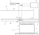
- FIG. 1 is a diagram showing a schematic configuration of a positioning device 20 when applied to a positioning device 20 to which a motion guide device 1 according to the present invention is applied.
- the positioning device 20 includes actuators 17 and 170 for changing the position of the table 80 on which the conveyed product 40 is placed, a control device 30 for controlling the moving speed of the table 80 by the actuators 17 and 170, and the like. It has. Further, the positioning device 20 includes the motion guide device 1 for supporting the table 80 on which the conveyed product 40 is placed movably in the first axis direction and the second axis direction orthogonal to the first axis direction. Used.
- the first axis is referred to as “X-axis” and the second axis is referred to as “Y-axis”.
- FIG. 2 is a diagram illustrating a schematic configuration of the motion guide apparatus 1.
- the motion guide device 1 includes a first guide portion 1a, a second guide portion 1b, strain gauges 2a to 2b, 3a to 3b, a linear encoder 4, and an information processing device 10. Prepare.
- FIG. 3 is a diagram illustrating an appearance of the motion guide device 1.
- 3A is an external perspective view when the motion guide apparatus 1 is viewed from an oblique front
- FIG. 3B is an external perspective view when the motion guide apparatus 1 is viewed from an oblique back.
- the first guide portion 1a in the present embodiment is an example of the first rail 11 (the “first track member” in the present application) extending in the X-axis direction.
- a first carriage 12 assembled so as to be relatively movable along the X-axis direction of the first rail 11, a table 8 fixed to the first carriage 12, a support member 13 fixed to the table 8, and a support And a back plate 130 attached to the member 13 via stays 131a and 131b.
- FIG. 4 is a diagram showing the structure of the first rail 11.
- 4 (a) is a plan view of the first rail 11
- FIG. 4 (b) is a cross-sectional view of the first rail 11
- FIG. 4 (c) is an AA view in FIG. 4 (b). It is a figure which shows a cross section.
- the first rail 11 includes an outer rail 11a having a substantially U-shaped cross section.
- Two pairs of upper and lower rolling grooves 11b are provided on a pair of inner surfaces facing each other of the outer rail 11a.
- the cross section of the rolling groove 11b is arcuate.
- the outer rail 11a accommodates an inner block 11c that is movable in the longitudinal direction (X-axis direction) of the outer rail 11a.
- the first carriage 12 is fixed to the upper surface of the inner block 11c with a bolt or the like (the combination of the inner block 11c and the first carriage 12 is an example of the “first moving member” in the present application).
- On both side surfaces of the inner block 11c there are provided two upper and lower rolling grooves 11d facing the rolling grooves 11b of the outer rail 11a.
- the load transfer path formed by the rolling groove 11b of the outer rail 11a and the rolling groove 11d of the inner block 11c is a return path 11e formed inside the inner block 11c as shown in FIG.
- a pair of direction change paths 11f constitute a circulation path of the track strip, and a plurality of balls 16 (an example of the “rolling element” in the present application) are accommodated in the circulation path.
- the screw shaft 11g is accommodated in the central portion inside the outer rail 11a so as to be rotatable in the circumferential direction.
- the screw shaft 11g is screwed into a ball screw portion 11h formed at the central portion of the inner block 11c.
- the inner block 11c is moved in the longitudinal direction (X-axis direction) of the outer rail 11a.
- bowl 16 interposed between them rolls a load rolling path.
- the ball 16 rolled to one end of the load rolling path is introduced into one direction changing path 11f, and then returns to the other end of the load rolling path via the return path 11e and the other direction changing path 11f in order.
- the second guide portion 1b is supported by the first guide portion 1a so as to be relatively movable along the X-axis direction and extends along the Y-axis direction (referred to as “second” in the present application).
- a second carriage 120 that is assembled so as to be relatively movable along the Y-axis direction of the second rail 110.
- An L-shaped table 80 is attached to the second carriage 120, and the conveyed product 40 is placed on the table 80.
- the structure of the second rail 110 is the same as that of the first rail 11 described above.
- the combination of the inner block accommodated in the second rail 110 and the second carriage 120 corresponds to the “second moving member” of the present invention.
- the motion guide device 1 of the present embodiment in a state where the base end side (the right side in FIG. 3A) of the second rail 110 in the Y-axis direction is placed on the support member 13, The first guide portion 1a and the second guide portion 1b are connected to each other by fixing the second rail 110 to the back plate 130 with a bolt or the like.
- the plate-like table 8 is attached to the first carriage 12 of the first guide portion 1 a, and the support member 13 is fixed to the table 8.
- the support member 13 of this embodiment is a plate-like member formed so that the length in the Y-axis direction is longer than that of the table 8.
- the support member 13 has the same position as the base end of the table 8 at the base end (left end portion in FIG. 5) in the Y-axis direction, and the position of the tip end (right end portion in FIG. 5) in the Y-axis direction.
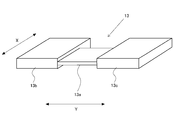
- the support member 13 has a base portion 13b and a tip portion where the thickness and width of the intermediate portion (intermediate portion) 13a between the base end and the tip end in the Y-axis direction are the same. It is formed to be smaller than 13c. That is, the support member 13 is formed so that the rigidity of the intermediate portion 13a described above is smaller than that of the proximal end portion 13b and the distal end portion 13c.
- the length of the intermediate portion 13a in the Y-axis direction is such that when the back plate 130 is attached to the support member 13, the position of the base end of the intermediate portion 13a in the Y-axis direction is closer to the base end side than the tip of the table 8.
- the position of the tip of the intermediate portion 13a in the Y-axis direction is determined so as to be located on the tip side from the tip of the table 8. More preferably, as shown in FIG. 7, the position of the center line C of the intermediate portion 13a in the Y-axis direction is within a range in which the second carriage 120 is movable in the second guide portion 1b (a range indicated by an arrow Rm in FIG. 7).
- the length of the intermediate portion 13a is determined so that it is positioned on the base end side in the Y-axis direction from the base end side end point (left end point Ep in FIG. 7).
- the support member 13 configured as described above is connected to the table 8 by fixing the base end portion 13b of the support member 13 and the table 8 with bolts or the like. Further, the support member 13 is connected to the back plate 130 by fixing a portion 13c on the front end side of the support member 13 and the back plate 130 via stays 131a and 131b.
- the part 13b on one end side of the support member 13 is referred to as “table fixing part 13b”
- the part 13c on the other end side of the support member 13 is referred to as “back plate fixing part 13c”.
- a stopper 131c is attached to the base end portion of the back plate 130 in the Y-axis direction.
- the stopper 131c is fixed to the back plate 130 and a bolt or the like, but is not fixed to the table fixing portion 13b of the support member 13. Further, the shape and attachment position of the stopper 131c are determined so that the bottom surface of the stopper 131c contacts the surface of the table fixing portion 13b in a state where the support member 13 is not bent or distorted.
- the base ends of the table 8 and the support member 13 in the Y-axis direction protrude from the base end of the first carriage 12.
- the 2nd actuator 170 attached to the end of the 2nd rail 110 is mounted in the protrusion part. This is because the load resulting from the weight of the second actuator 170 is applied to the approximate center of the first carriage 12 in the Y-axis direction.
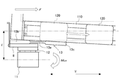
- the table fixing portion 13b of the support member 13 is not fixed to the back plate 130, and the back plate fixing portion 13c of the support member 13 is fixed to the back plate 130. Therefore, as shown in FIG.
- the rolling moment Mcx acting clockwise with respect to the X axis of the motion guide device 1 is generated, the base end portion of the second rail 110 is allowed to be separated from the support member 13. Thereby, a bending stress corresponding to the rolling moment Mcx acts on the support member 13.
- the support member 13 of this embodiment is comprised so that the rigidity of the intermediate part 13a may become relatively small, when the bending stress according to said rolling moment Mcx acts on the support member 13, this said The intermediate portion 13a of the support member 13 can be locally bent. That is, a bending stress corresponding to the rolling moment Mcx can be applied locally to the intermediate portion 13a of the support member 13.
- the support member 13 bends when the rolling moment Mcx acting clockwise in FIG. 12 is generated.
- the bending of the support member 13 when a rolling moment acting counterclockwise in FIG. 12 is generated can be restricted.
- each of the strain gauges 2a to 2b and 3a to 3b is, for example, a metal strain gauge using an isotropic conductor or a semiconductor strain gauge using a piezoresistance effect, and detects a bending stress applied to the support member 13.
- the four strain gauges 2 a to 2 b and 3 a to 3 b are attached to the intermediate portion 13 a of the support member 13.
- the two strain gauges 2a to 2b are attached to the surface of the intermediate portion 13a of the support member 13 as shown in FIG.
- the mounting positions of the strain gauges 2a and 2b in the Y-axis direction are positions where the strain is most likely to increase in the intermediate portion 13a (for example, on the center line C of the intermediate portion 13a in the Y-axis direction).
- the attachment positions of the strain gauges 2a and 2b in the X-axis direction are symmetrical with respect to the center line C ′ of the second rail 110.
- the remaining two strain gauges 3a and 3b are attached to the back surface of the intermediate portion 13a as shown in FIG. 8B.
- strain detection circuit configured using the four strain gauges 2a to 2b and 3a to 3b is referred to as a “stress detection circuit”.
- the attachment positions of the strain gauges 2a to 2b and 3a to 3b in the Y-axis direction in other words, the position of the center line C of the intermediate portion 13a in the Y-axis direction are as shown in FIG.
- the second carriage 120 is disposed closer to the base end side in the Y-axis direction than the end point Ep on the base end side in the movable range of the second carriage 120, the amount of bending at the mounting position of the strain gauges 2a to 2b and 3a to 3b tends to be large. . As a result, the correlation between the bending stress detected by the stress detection circuit and the rolling moment Mcx can be further enhanced.
- the linear encoder 4 detects the position of the second carriage 120 in the X-axis direction and the Y-axis direction, and outputs the detection result to the information processing apparatus 10.
- the linear encoder 4 includes, for example, a first scale attached to the first rail 11, a second scale attached to the second rail 110, a first head attached to the first carriage 12 and reading the first scale, and a second scale. A second head that is attached to the carriage 120 and reads the second scale is provided.
- the position detecting means for detecting the position of the second carriage 120 is not limited to the linear encoder, and the angle of the motor that drives the ball screw of the first rail 11 and the ball screw of the second rail 110 are driven. It is also possible to use a rotary encoder that detects the angle of each motor to be operated.
- FIG. 9 is a block diagram in which a functional unit realized by the information processing apparatus 10 included in the motion guide apparatus 1 is imaged.
- the information processing apparatus 10 includes an arithmetic device for processing the detection value of the stress detection circuit described above, a memory for temporarily storing the information, and various functions by executing predetermined control programs by the arithmetic device. Is demonstrated.
- the information processing apparatus 10 according to the present embodiment includes an acquisition unit 101 and an output unit 102 as main functional units.
- the acquisition unit 101 reads the detection value of the stress detection circuit when the table 80 is moved in the Y-axis direction with the conveyed product 40 placed on the table 80, and the moment information is obtained from the detection position. To get.
- the moment information here is information related to the rolling moment Mcx acting around the X axis of the motion guide device 1. A specific method for acquiring this moment information will be described later.
- the output unit 102 Based on the moment information acquired by the acquisition unit 101, the output unit 102 generates correction information for correcting the control parameter used when the control device 30 moves the conveyed product 40 in the Y-axis direction, The correction information is output to the control device 30. A specific method for generating correction information will be described later.
- Mcx m * a * L (3)
- the information processing device 10 of the motion guide device 1 displays moment information regarding the rolling moment Mcx. Acquisition information is generated, and correction information for correcting the target speed is generated based on the moment information. Further, the generated correction information is output from the information processing apparatus 10 to the control apparatus 30 side.
- the acquisition process illustrated in FIG. 11 is a process that is executed by the acquisition unit 101 when triggered by the movement of the conveyed product 40 from the proximal end side to the distal end side in the Y-axis direction.
- the acquisition unit 101 reads the detection value (the bending stress acting on the support member 13) of the stress detection circuit.
- the movement is performed as described above.
- a rolling moment Mcx acting around the X axis of the guide device 1 is generated.
- the rolling moment Mcx that works clockwise with respect to the X axis is generated.
- a bending stress corresponding to the rolling moment Mcx acts on the support member 13, and the intermediate portion 13a of the support member 13 is locally bent.
- the strain gauges 2a to 2b and 3a to 3b constituting the stress detection circuit are attached to the most flexible position in the intermediate portion 13a of the support member 13, the bending detected by the stress detection circuit is provided.
- the correlation between the stress and the rolling moment Mcx increases.
- the acquisition unit 101 acquires moment information based on the detection value of the stress detection circuit read in S101.
- the magnitude of the rolling moment Mcx is used as the moment information.
- the correlation between the magnitude of the bending stress detected by the stress detection circuit and the magnitude of the rolling moment Mcx is obtained in advance based on the results of experiments and simulations, and the information processing apparatus 10 is in the form of a map or a functional expression. You may make it memorize
- the acquisition unit 101 may derive the magnitude of the rolling moment Mcx by accessing the map or the function expression using the magnitude of the bending stress read in the process of S101 as an argument.
- FIG. 13 is a process executed by the output unit 102 triggered by the moment information generated by the acquisition unit 101.
- the output unit 102 determines whether or not the magnitude of the rolling moment Mcx acquired by the acquisition unit 101 is greater than a predetermined threshold value.
- the predetermined threshold here is a value that is assumed to cause performance degradation or failure of the motion guide device 1 when the rolling moment Mcx is larger than the predetermined threshold, and is obtained in advance based on results of experiments, simulations, and the like. Shall be kept. If a negative determination is made in S201, the output unit 102 does not execute the correction information generation process and output process. On the other hand, if an affirmative determination is made in S201, the output unit 102 proceeds to S202, and performs correction information generation processing and correction processing.
- the output unit 102 first generates correction information based on the magnitude of the rolling moment Mcx acquired by the acquisition unit 101.
- the correction information is information for correcting a control parameter used when the conveyed product 40 is moved in the Y-axis direction. Specifically, the target speed when the conveyed product 40 is moved in the Y-axis direction is decelerated. It is information for correcting to the side.
- the output unit 102 calculates a correction value ⁇ v based on the difference ⁇ Mcx.
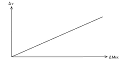
- the correction value ⁇ v is determined so as to increase as the difference ⁇ Mcx increases. 14 may be obtained in advance based on the results of experiments and simulations and stored in the memory of the information processing apparatus 10 in the form of a function equation or a map.
- the output unit 102 outputs the correction value ⁇ v obtained by the above-described procedure to the control device 30 side as correction information.
- the output unit 102 outputs the correction information generated in S202 to the control device 30.
- the correction process illustrated in FIG. 15 is a process executed by the control device 30 when the correction information is output from the output unit 102 as a trigger.
- the control device 30 corrects the target speed of the conveyed product 40 in the Y-axis direction based on the correction information output from the output unit 102. Specifically, the control device 30 corrects the target speed by a method of subtracting a correction value ⁇ v as correction information output from the output unit 102 from the current target speed.
- control device 30 controls the second actuator 170 for moving the conveyed product 40 to the Y axis according to the corrected target speed obtained in S301.
- the control device 30 when the rolling moment Mcx acting around the X axis of the motion guide device 1 becomes larger than a predetermined threshold, the control device 30 outputs from the output unit 102.
- the target speed used when moving the conveyed product 40 in the Y-axis direction can be corrected to the deceleration side using the correction information. As a result, it is possible to suppress the performance degradation and failure of the motion guide apparatus 1 due to the excessive rolling moment Mcx.
- the output unit 102 relates to the movement of the conveyed product 40 in the Y-axis direction separately from the correction information as described above when the magnitude of the rolling moment Mcx becomes larger than the predetermined threshold.
- the alarm information may be output to the control device 30 side.
- the movement of the conveyed product 40 is stopped on the control device 30 side, the target speed of the conveyed product 40 is adjusted, or the movement guide device 1 is inspected. It becomes possible to do.
- the acquisition unit 101 performs the rolling moment Mcx for each position of the second carriage 120 detected by the linear encoder 4. May be obtained.
- the output unit 102 may identify the position where the rolling moment Mcx exceeds the predetermined threshold by comparing the rolling moment Mcx at each position of the second carriage 120 with a predetermined threshold.
- the output part 102 may output the information regarding the position where the rolling moment Mcx exceeded the predetermined threshold with the above-mentioned correction information to the control apparatus 30 side.
- the control device 30 side can also perform inspections, repairs, and the like of the location specified by the position information.
- the configuration in which the inner block is assembled to the first rail (or the second rail) via the rolling elements is taken as an example.
- the inner block is in contrast to the first rail (or the second rail).
- And may be assembled so as to be relatively slidable in the X-axis direction.
- the configuration in which the thickness and width of the intermediate portion of the obstacle member are made smaller than those of the table fixing portion and the back plate fixing portion is exemplified.
- only one of the thickness and width of the intermediate portion is described. May be smaller than the table fixing portion and the back plate fixing portion.
Landscapes
- Engineering & Computer Science (AREA)
- General Engineering & Computer Science (AREA)
- Physics & Mathematics (AREA)
- General Physics & Mathematics (AREA)
- Mechanical Engineering (AREA)
- Bearings For Parts Moving Linearly (AREA)
- Force Measurement Appropriate To Specific Purposes (AREA)
Abstract
第1軸方向及び第2軸方向へ搬送物を移動自在に支持する2軸式の運動案内装置において、搬送物を第2軸方向へ移動させる際に該運動案内装置の第1軸まわりに働くローリングモーメントを検知可能にする。第1軸方向及び第2軸方向へ搬送物を移動自在に支持する運動案内装置において、第1案内部と第2案内部との間に支承部材を介設する。支承部材は、第2軸方向における基端側の部位が第1案内部に固定され、且つ第2軸方向における先端側の部位が第2案内部に固定され、且つそれら2カ所の固定箇所の中間部にひずみゲージが配置される。そして、搬送物が第2軸方向の基端側から先端側へ移動される際のひずみゲージの検出値に基づいて、該運動案内装置の第1軸まわりに働くローリングモーメントに関するモーメント情報を取得する。
Description
本発明は、第1軸方向及び該第1軸と直交する第2軸方向へ搬送対象たる搬送物を移動可能に支持する2軸式の運動案内装置における、モーメント検知装置に関する。
位置決め装置等では、ワーク等の搬送物を移動自在に支持する運動案内装置が用いられる場合がある。その場合の運動案内装置としては、例えば、第1軸方向に沿って移動体を移動可能に支持する第1案内部と、第1軸と直交する第2軸方向に沿って移動体を移動可能に支持する第2案内部と、を組み合わせた2軸式の運動案内装置が知られている(例えば、特許文献1を参照)。その際、第1案内部は、第1軸方向に延在する転動溝が形成された第1軌道部材と、該第1軌道部材の転動溝内を転動可能に配置された転動体を介して配置され且つ第1軸方向に沿って相対的に移動可能な第1移動部材と、を備える。また、第2案内部は、第1案内部によって第1軸方向へ移動自在に支持され且つ第2軸方向に沿って延在する転動溝が形成された第2軌道部材と、該第2軌道部材の転動溝内を転動可能に配置された転動体を介して配置され且つ第2軸方向に沿って相対的に移動自在な第2移動部材と、を備える。このような2軸式の運動案内装置を用いる位置決め装置等では、第2移動部材に搬送用のテーブルを取り付け、そのテーブルに搬送物を載置することで、搬送物を第1軸方向及び第2軸方向へ移動自在に支持することができる。
上記した2軸式の運動案内装置において搬送物が載置された第2移動部材が第2軸方向へ移動すると、該運動案内装置の第1軸まわりに働くモーメント(ローリングモーメント)が発生する。その際、搬送物の第2軸方向への移動速度が過大になると、それに伴って上記のローリングモーメントが過大になることで、運動案内装置の性能低下や故障を招く可能性がある。このような問題を解決するためには、第2移動部材の第2軸方向への移動速度を適正な速度に調整すべく、運動案内装置の第1軸まわりに働くローリングモーメントを検知する必要がある。
本発明は、上記した実情に鑑みてなされたものであり、その目的は、第1軸方向及び第1軸に直交する第2軸方向へ搬送物を移動自在に支持する2軸式の運動案内装置において、搬送物を第2軸方向へ移動させる際に該運動案内装置の第1軸まわりに働くローリングモーメントを検知することができる技術を提供することにある。
本発明は、上記課題を解決するために、第1軸方向及び該第1軸に直交する第2軸方向へ搬送物を移動自在に支持する運動案内装置において、第2軸方向における基端側の部位が第1案内部に固定され、且つ第2軸方向における先端側の部位が第2案内部に固定される支承部材を設けて、該支承部材の中間部にひずみゲージを取り付けることで、搬送物が第2軸方向へ移動される際の支承部材のひずみに基づいて、該運動案内装置の第1軸まわりに働くローリングモーメントに関するモーメント情報を取得するようにした。
詳細には、本発明は、第1軸方向に沿って延在する第1軌道部材と、前記第1軌道部材に対して第1軸方向に沿って相対的に移動可能に組み付けられる第1移動部材と、を有する第1案内部と、前記第1案内部によって第1軸方向に沿って相対的に移動可能に支持され且つ第1軸に直交する第2軸方向に沿って延在する第2軌道部材と、前記第2軌道部材に対して第2軸方向に沿って相対的に移動可能に組み付けられ且つ搬送対象である搬送物を支持する第2移動部材と、有する第2案内部と、を備える運動案内装置に適用されるモーメント検知装置である。該モーメント検知装置は、第2軸方向における基端側の部位が前記第1移動部材に固定され且つ第2軸方向における先端側の部位が前記第1移動部材から突出しつつその突出部分に前記第2軌道部材が固定される支承部材と、前記支承部材における前記第1移動部材が固定される部位と前記第2軌道部材が固定される部位との間の中間部に取り付けられ、該中間部の第2軸方向におけるひずみを検出するひずみゲージと、前記運動案内装置により搬送物が第2軸方向の基端側から先端側へ移動される際の前記ひずみゲージの検出値に基づいて、該運動案内装置の第1軸まわりに働くローリングモーメントに関するモーメント情報を取得する取得部と、を備える。
このように構成される運動案内装置のモーメント検知装置において、搬送物が第2軸方向の基端側から先端側へ移動させられると、該運動案内装置の第1軸まわりに働くローリングモーメントが発生する。ここで、本発明の支承部材は、第2軸方向における基端側の部位が第1移動部材に固定され、且つ第2軸方向における先端側の突出部分が第2軌道部材に固定される。そのため、上記のローリングモーメントが発生した際に、該ローリングモーメントの大きさに応じた曲げ応力が支承部材に作用することになり、それに応じて該支承部材が撓むことになる。その際の中間部の撓み量は、上記のローリングモーメントの大きさに相関する。よって、運動案内装置により搬送物が第2軸方向の基端側から先端側へ移動される際のひずみゲージの検出値は、該運動案内装置の第1軸まわりに働くローリングモーメントに相関した値になる。その結果、運動案内装置により搬送物が第2軸方向の基端側から先端側へ移動される際のひずみゲージの検出値に基づいて、運動案内装置の第1軸まわりに働くローリングモーメントに関するモーメント情報を取得することが可能になる。
本発明によれば、第1軸方向及び該第1軸と直交する第2軸方向へ搬送物を移動自在に支持する2軸式の運動案内装置において、搬送物を第2軸方向へ移動させる際に該運動案内装置の第1軸まわりに働くローリングモーメントを検知することができる。
以下、本発明の具体的な実施形態について図面に基づいて説明する。本実施形態に記載されている構成部品の寸法、材質、形状、その相対配置等は、特に記載がない限りは発明の技術的範囲をそれらのみに限定する趣旨のものではない。
図1は、本発明に係わる運動案内装置1を適用する位置決め装置20に適用する場合における、該位置決め装置20の概略構成を示す図である。位置決め装置20は、搬送物40が載置されるテーブル80の位置を変更するためのアクチュエータ17、170と、それらアクチュエータ17、170によるテーブル80の移動速度等を制御するための制御装置30と、を備えている。また、上記した位置決め装置20には、搬送物40が載置されるテーブル80を第1軸方向及び第1軸方向に直交する第2軸方向に移動自在に支持するための運動案内装置1が用いられる。なお、以下では、第1軸を「X軸」と称し、第2軸を「Y軸」と称するものとする。
<運動案内装置の概略構成>
図2は、運動案内装置1の概略構成を示す図である。運動案内装置1は、図2に示すように、第1案内部1aと、第2案内部1bと、ひずみゲージ2a~2b、3a~3bと、リニアエンコーダ4と、情報処理装置10と、を備える。
図2は、運動案内装置1の概略構成を示す図である。運動案内装置1は、図2に示すように、第1案内部1aと、第2案内部1bと、ひずみゲージ2a~2b、3a~3bと、リニアエンコーダ4と、情報処理装置10と、を備える。
ここで、第1案内部1aの構成について、図3~図4に基づいて説明する。図3は、運動案内装置1の外観を示す図である。図3中(a)は運動案内装置1を斜め正面から見たときの外観斜視図であり、図3中(b)は運動案内装置1を斜め背面から見たときの外観斜視図である。
本実施形態における第1案内部1aは、図3中(a)、(b)に示すように、X軸方向に延在する第1レール11(本願でいう「第1軌道部材」の一例である)と、第1レール11のX軸方向沿いに相対移動可能に組み付けられる第1キャリッジ12と、第1キャリッジ12に固定されるテーブル8と、テーブル8に固定される支承部材13と、支承部材13にステー131a、131bを介して取り付けられる背板130と、を備える。
図4は、第1レール11の構造を示す図である。なお、図4中(a)は第1レール11の平面図であり、図4中(b)は第1レール11の断面図であり、図4中(c)は(b)におけるA-A'断面を示す図である。
第1レール11は、図4中(b)に示すように、その断面が略U字型に形成されたアウターレール11aを備える。アウターレール11aの互いに対向する一対の内側面には、上下二条の転動溝11bがそれぞれ設けられる。転動溝11bの断面は円弧状である。アウターレール11aには、該アウターレール11aの長手方向(X軸方向)に移動自在なインナーブロック11cが収容される。
インナーブロック11cの上面には、第1キャリッジ12がボルト等によって固定される(これらインナーブロック11cと第1キャリッジ12との組合せは、本願でいう「第1移動部材」の一例である)。インナーブロック11cの両側面には、アウターレール11aの転動溝11bに対向する上下二条の転動溝11dがそれぞれ設けられる。
アウターレール11aの転動溝11bとインナーブロック11cの転動溝11dとによって形成される負荷転送路は、図4中(c)に示すように、インナーブロック11cの内部に形成される戻し路11eと一対の方向転換路11fとによってトラック条の循環路を構成しており、その循環路に複数の玉16(本願でいう「転動体」の一例である)が収容される。
また、アウターレール11aの内部の中央部には、図4中(a)に示すように、ねじ軸11gが周方向へ回転自在に収容される。このねじ軸11gは、インナーブロック11cの中央部に形成されたボールねじ部11hに螺合されている。このように構成される第1レール11において、第1アクチュエータ17によりねじ軸11gが回転させられると、インナーブロック11cがアウターレール11aの長手方向(X軸方向)へ移動せしめられる。そして、アウターレール11aに対してインナーブロック11cが相対的に移動すると、それらの間に介在する玉16が負荷転走路を転がる。負荷転走路の一端まで転がった玉16は、一方の方向転換路11fに導入され、次いで戻し路11e及び他方の方向転換路11fを順次経由して負荷転走路の他端に戻る。
一方、第2案内部1bは、第1案内部1aによってX軸方向に沿って相対的に移動可能に支持され且つY軸方向に沿って延在する第2レール110(本願でいう「第2軌道部材」の一例である)と、第2レール110のY軸方向に沿いに相対移動可能に組み付けられる第2キャリッジ120と、を備える。第2キャリッジ120には、断面L字型のテーブル80が取り付けられ、そのテーブル80に搬送物40が載置される。ここで、第2レール110の構造は、前述した第1レール11と同様である。そして、第2レール110に収容されるインナーブロックと第2キャリッジ120との組合せが本発明の「第2移動部材」に相当する。
また、本実施形態の運動案内装置1では、第2レール110のY軸方向における基端側(図3中(a)における右側)の部位を上記の支承部材13に載置した状態で、該第2レール110を上記の背板130にボルト等で固定することで、第1案内部1aと第2案内部1bとを相互に連結している。
<第1案内部と第2案内部の連結方法>
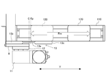
ここで、本実施形態における、第1案内部1aと第2案内部1bとの連結方法について詳説する。先ず、第1案内部1aの第1キャリッジ12には、図5に示すように、板状のテーブル8が取り付けられ、そのテーブル8に支承部材13が固定される。本実施形態の支承部材13は、Y軸方向における長さがテーブル8より長くなるように形成された、板状の部材である。該支承部材13は、Y軸方向における基端(図5中の左端部)の位置がテーブル8の基端と同位置となり、且つY軸方向における先端(図5中の右端部)の位置がテーブル8の先端よりも突出するように、テーブル8に固定される。また、該支承部材13は、図6に示すように、Y軸方向における基端と先端との中間の部位(中間部)13aの厚さ及び幅が基端側の部位13b及び先端側の部位13cより小さくなるように形成される。すなわち、該支承部材13は、上記した中間部13aの剛性が基端側の部位13b及び先端側の部位13cより小さくなるように形成される。中間部13aのY軸方向の長さは、支承部材13に背板130が取り付けられた際に、Y軸方向における中間部13aの基端の位置がテーブル8の先端より基端側に位置し、且つY軸方向における中間部13aの先端の位置がテーブル8の先端より先端側に位置するように定められる。より好ましくは、図7に示すように、Y軸方向における中間部13aの中心線Cの位置が、第2案内部1bにおいて第2キャリッジ120が可動する範囲(図7中の矢印Rmで示す範囲)の基端側の端点(図7中の左側の端点Ep)よりもY軸方向における基端側の位置となるように、中間部13aの長さが定められる。
ここで、本実施形態における、第1案内部1aと第2案内部1bとの連結方法について詳説する。先ず、第1案内部1aの第1キャリッジ12には、図5に示すように、板状のテーブル8が取り付けられ、そのテーブル8に支承部材13が固定される。本実施形態の支承部材13は、Y軸方向における長さがテーブル8より長くなるように形成された、板状の部材である。該支承部材13は、Y軸方向における基端(図5中の左端部)の位置がテーブル8の基端と同位置となり、且つY軸方向における先端(図5中の右端部)の位置がテーブル8の先端よりも突出するように、テーブル8に固定される。また、該支承部材13は、図6に示すように、Y軸方向における基端と先端との中間の部位(中間部)13aの厚さ及び幅が基端側の部位13b及び先端側の部位13cより小さくなるように形成される。すなわち、該支承部材13は、上記した中間部13aの剛性が基端側の部位13b及び先端側の部位13cより小さくなるように形成される。中間部13aのY軸方向の長さは、支承部材13に背板130が取り付けられた際に、Y軸方向における中間部13aの基端の位置がテーブル8の先端より基端側に位置し、且つY軸方向における中間部13aの先端の位置がテーブル8の先端より先端側に位置するように定められる。より好ましくは、図7に示すように、Y軸方向における中間部13aの中心線Cの位置が、第2案内部1bにおいて第2キャリッジ120が可動する範囲(図7中の矢印Rmで示す範囲)の基端側の端点(図7中の左側の端点Ep)よりもY軸方向における基端側の位置となるように、中間部13aの長さが定められる。
上記したように構成される支承部材13は、該支承部材13の基端側の部位13bとテーブル8とをボルト等で固定することにより、テーブル8に連結される。また、支承部材13は、該支承部材13の先端側の部位13cと背板130とをステー131a、131bを介して固定することにより、背板130と連結される。以下では、支承部材13の一端側の部位13bを「テーブル固定部13b」と称し、支承部材13の他端側の部位13cを「背板固定部13c」と称する。
ここで図5に戻り、背板130のY軸方向における基端部には、ストッパ131cが取り付けられる。ストッパ131cは、背板130とボルト等によって固定される一方で、支承部材13のテーブル固定部13bとは固定されないものとする。さらに、支承部材13に撓みや歪みが発生していない状態において、該ストッパ131cの底面がテーブル固定部13bの表面と当接するように、ストッパ131cの形状や取り付け位置が定められる。
また、本実施形態においては、テーブル8及び支承部材13のY軸方向における基端は、第1キャリッジ12の基端より突出している。そして、その突出部分には、第2レール110の一端に取り付けられる第2アクチュエータ170が載置される。これは、第2アクチュエータ170の重量に起因する荷重がY軸方向における第1キャリッジ12の略中心にかかるようにするためである。
上記した連結方法によると、支承部材13のテーブル固定部13bが背板130に固定されず、且つ支承部材13の背板固定部13cが背板130に固定されるため、図12に示すように、運動案内装置1のX軸に対して時計回りに働くローリングモーメントMcxが発生した際に、第2レール110の基端部が支承部材13から離間することが許容される。それにより、上記のローリングモーメントMcxに応じた曲げ応力が支承部材13に作用することになる。そして、本実施形態の支承部材13は、中間部13aの剛性が相対的に小さくなるように構成されるため、上記のローリングモーメントMcxに応じた曲げ応力が支承部材13に作用した際に、該支承部材13の中間部13aを局所的に撓ませることができる。つまり、上記のローリングモーメントMcxに応じた曲げ応力を、支承部材13の中間部13aへ局所的に働かせることができる。
また、上記した連結方法によると、背板130のY軸方向における基端部にストッパ131cが取り付けられるため、図12中の時計回りに働くローリングモーメントMcxが発生した際に支承部材13が撓むことを許容する一方で、図12中の反時計回りに働くローリングモーメントが発生した際に支承部材13が撓むことを規制することができる。
<ひずみゲージの構成>
次に、運動案内装置1に組み込まれるひずみゲージ2a~2b、3a~3bの構成について述べる。各ひずみゲージ2a~2b、3a~3bは、例えば、等方性導体を用いた金属ひずみゲージ、又はピエゾ抵抗効果を利用した半導体ひずみゲージであり、支承部材13にかかる曲げ応力を検出する。本実施形態では、4つのひずみゲージ2a~2b、3a~3bは、支承部材13の中間部13aに取り付けられる。4つのひずみゲージ2a~2b、3a~3bのうち、2つのひずみゲージ2a~2bは、図8中(a)に示すように、支承部材13における中間部13aの表面に取り付けられる。ひずみゲージ2a、2bのY軸方向における取り付け位置は、該中間部13aにおいてひずみが最も大きくなり易い位置(例えば、Y軸方向における中間部13aの中心線C上)とする。また、ひずみゲージ2a、2bのX軸方向における取り付け位置は、第2レール110の中心線C'を基準として対称になる位置とする。次に、4つのひずみゲージ2a~2b、3a~3bのうち、残りの2つのひずみゲージ3a、3bは、図8中(b)に示すように、中間部13aの裏面に取り付けられる。これら2つのひずみゲージ3a、3bのX軸方向及びY軸方向における取り付け位置は、上記したひずみゲージ2a、2bと同様である。そして、上記したように配置される4つのひずみゲージ2a~2b、3a~3bは、図8中(c)に示すようなブリッジ回路を構成することで、支承部材13にかかる曲げ応力に応じた電圧を出力する。以下では、4つのひずみゲージ2a~2b、3a~3bを用いて構成されるブリッジ回路を「応力検出回路」と称する。
次に、運動案内装置1に組み込まれるひずみゲージ2a~2b、3a~3bの構成について述べる。各ひずみゲージ2a~2b、3a~3bは、例えば、等方性導体を用いた金属ひずみゲージ、又はピエゾ抵抗効果を利用した半導体ひずみゲージであり、支承部材13にかかる曲げ応力を検出する。本実施形態では、4つのひずみゲージ2a~2b、3a~3bは、支承部材13の中間部13aに取り付けられる。4つのひずみゲージ2a~2b、3a~3bのうち、2つのひずみゲージ2a~2bは、図8中(a)に示すように、支承部材13における中間部13aの表面に取り付けられる。ひずみゲージ2a、2bのY軸方向における取り付け位置は、該中間部13aにおいてひずみが最も大きくなり易い位置(例えば、Y軸方向における中間部13aの中心線C上)とする。また、ひずみゲージ2a、2bのX軸方向における取り付け位置は、第2レール110の中心線C'を基準として対称になる位置とする。次に、4つのひずみゲージ2a~2b、3a~3bのうち、残りの2つのひずみゲージ3a、3bは、図8中(b)に示すように、中間部13aの裏面に取り付けられる。これら2つのひずみゲージ3a、3bのX軸方向及びY軸方向における取り付け位置は、上記したひずみゲージ2a、2bと同様である。そして、上記したように配置される4つのひずみゲージ2a~2b、3a~3bは、図8中(c)に示すようなブリッジ回路を構成することで、支承部材13にかかる曲げ応力に応じた電圧を出力する。以下では、4つのひずみゲージ2a~2b、3a~3bを用いて構成されるブリッジ回路を「応力検出回路」と称する。
上記したように、ひずみゲージ2a~2b、3a~3bが中間部13aに取り付けられると、運動案内装置1のX軸まわり働くローリングモーメントMcxが発生した際に、応力検出回路により検出される曲げ応力と上記のローリングモーメントMcxとの相関が高くなる。特に、本実施形態では、Y軸方向におけるひずみゲージ2a~2b、3a~3bの取り付け位置、言い換えると、Y軸方向における中間部13aの中心線Cの位置は、前述の図7に示したように、第2キャリッジ120の可動範囲における基端側の端点EpよりもY軸方向の基端側に配置されるため、ひずみゲージ2a~2b、3a~3bの取り付け位置における撓み量が大きくなり易い。その結果、応力検出回路によって検出される曲げ応力と上記のローリングモーメントMcxとの相関を一層高めることができる。
<リニアエンコーダの構成>
リニアエンコーダ4は、第2キャリッジ120のX軸方向及びY軸方向の位置を検出して、その検出結果を情報処理装置10へ出力する。このリニアエンコーダ4は、例えば、第1レール11に取り付けられる第1スケール、第2レール110に取り付けられる第2スケール、第1キャリッジ12に取り付けられて第1スケールを読み取る第1ヘッド、及び第2キャリッジ120に取り付けられて第2スケールを読み取る第2ヘッドを備える。なお、第2キャリッジ120の位置を検出する位置検出手段は、リニアエンコーダに限定されるものではなく、第1レール11のボールねじを駆動するモータの角度、及び第2レール110のボールねじを駆動するモータの角度をそれぞれ検出するロータリーエンコーダを用いることもできる。
リニアエンコーダ4は、第2キャリッジ120のX軸方向及びY軸方向の位置を検出して、その検出結果を情報処理装置10へ出力する。このリニアエンコーダ4は、例えば、第1レール11に取り付けられる第1スケール、第2レール110に取り付けられる第2スケール、第1キャリッジ12に取り付けられて第1スケールを読み取る第1ヘッド、及び第2キャリッジ120に取り付けられて第2スケールを読み取る第2ヘッドを備える。なお、第2キャリッジ120の位置を検出する位置検出手段は、リニアエンコーダに限定されるものではなく、第1レール11のボールねじを駆動するモータの角度、及び第2レール110のボールねじを駆動するモータの角度をそれぞれ検出するロータリーエンコーダを用いることもできる。
<情報処理装置の機能構成>
図9は、運動案内装置1に含まれる、情報処理装置10により実現される機能部をイメージ化したブロック図である。情報処理装置10は、上記した応力検出回路の検出値を処理するための演算装置や一時的に記憶するメモリ等を有し、当該演算装置により所定の制御プログラムが実行されることで様々な機能が発揮される。本実施形態における情報処理装置10は、その主な機能部として、取得部101と出力部102とを備えている。
図9は、運動案内装置1に含まれる、情報処理装置10により実現される機能部をイメージ化したブロック図である。情報処理装置10は、上記した応力検出回路の検出値を処理するための演算装置や一時的に記憶するメモリ等を有し、当該演算装置により所定の制御プログラムが実行されることで様々な機能が発揮される。本実施形態における情報処理装置10は、その主な機能部として、取得部101と出力部102とを備えている。
取得部101は、テーブル80に搬送物40が載置された状態で該テーブル80をY軸方向へ移動させているときに、上記の応力検出回路の検出値を読み込み、その検出置からモーメント情報を取得する。ここでいうモーメント情報は、運動案内装置1のX軸まわりに働くローリングモーメントMcxに関わる情報である。このモーメント情報の具体的な取得方法については後述する。
出力部102は、取得部101により取得されたモーメント情報に基づいて、制御装置30が搬送物40をY軸方向へ移動させる際に用いられる制御パラメータを補正するための補正情報を生成して、その補正情報を制御装置30へ出力する。補正情報の具体的な生成方法については後述する。
<ローリングモーメントMcxの発生とその影響>
搬送物40を載置した状態のテーブル8が制御装置30によってY軸方向の基端側から先端側へ移動されると、図12に示すように、運動案内装置1のX軸まわりに働くローリングモーメントMcxが発生する。その場合のローリングモーメントMcxの大きさは、第2案内部1bが水平状態にある場合における第1案内部1aの軸心と第2案内部1bの軸心との距離をL、運動案内装置1のY軸方向に働く荷重をFとすると、例えば以下の式(1)で与えられる。
Mcx=F*L・・・(1)
搬送物40を載置した状態のテーブル8が制御装置30によってY軸方向の基端側から先端側へ移動されると、図12に示すように、運動案内装置1のX軸まわりに働くローリングモーメントMcxが発生する。その場合のローリングモーメントMcxの大きさは、第2案内部1bが水平状態にある場合における第1案内部1aの軸心と第2案内部1bの軸心との距離をL、運動案内装置1のY軸方向に働く荷重をFとすると、例えば以下の式(1)で与えられる。
Mcx=F*L・・・(1)
なお、Y軸方向の荷重Fは、搬送物40、テーブル8、及び第2移動部材を含む移動体の総質量をM、該移動体の加速度をaとすると、以下の式(2)で与えられる。
F=m*a・・・(2)
F=m*a・・・(2)
上記の式(1)、(2)から、上記のローリングモーメントMcxは、以下の式(3)で与えられることになる。
Mcx=m*a*L・・・(3)
Mcx=m*a*L・・・(3)
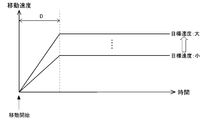
上記の式(3)によれば、搬送物40、テーブル80、及び第2キャリッジ120を含む移動体の加速度が大きくなると、それに伴って運動案内装置1のX軸まわりに働くローリングモーメントMcxが大きくなる。ここで、上記した移動体の移動速度が目標速度に達するまでの時間(時定数)を一定とすると、図10に示すように、該移動体がY軸方向へ移動し始めてから該移動体の移動速度が目標速度に到達するまでの期間(図10中の期間D)における、移動速度の増加率(加速度)は、目標速度が大きくなるほど大きくなる。そのため、制御装置30が搬送物40をY軸方向へ移動させる際の目標速度が過大になると、上記の期間Dにおける移動体の加速度が過大になることで、上記のローリングモーメントMcxが過大になる可能性がある。このようにしてローリングモーメントMcxが過大になると、運動案内装置1の性能低下や故障を招く可能性がある。
そこで、本実施形態では、制御装置30が搬送物40をY軸方向の基端側から先端側移動させているときに、運動案内装置1の情報処理装置10において、ローリングモーメントMcxに関するモーメント情報を取得し、そのモーメント情報に基づいて上記の目標速度を補正するための補正情報を生成するようにした。さらに、生成された補正情報は、情報処理装置10から制御装置30側へ出力されるようにした。
<取得部の機能>
ここで、情報処理装置10の取得部101による、モーメント情報の取得処理について、図11に基づいて説明する。図11に示す取得処理は、搬送物40がY軸方向の基端側から先端側への移動を開始したことをトリガとして、取得部101によって実行される処理である。
ここで、情報処理装置10の取得部101による、モーメント情報の取得処理について、図11に基づいて説明する。図11に示す取得処理は、搬送物40がY軸方向の基端側から先端側への移動を開始したことをトリガとして、取得部101によって実行される処理である。
S101の処理では、取得部101は、上記の応力検出回路の検出値(支承部材13に働く曲げ応力)を読み込む。ここで、搬送物40がY軸方向の基端側から先端側への移動を開始してから該搬送物40の移動速度が目標速度に到達するまでの期間Dでは、前述したように、運動案内装置1のX軸まわりに働くローリングモーメントMcxが発生する。詳細には、上記の期間Dでは、前述の図12に示したように、X軸に対して時計回りに働くローリングモーメントMcxが発生する。このようなローリングモーメントMcxが発生すると、該ローリングモーメントMcxに応じた曲げ応力が支承部材13に作用することで、支承部材13の中間部13aが局所的に撓むことになる。そして、本実施形態では、応力検出回路を構成するひずみゲージ2a~2b、3a~3bが、支承部材13の中間部13aにおいて最も撓み易い位置に取り付けられるため、該応力検出回路により検出される曲げ応力と上記のローリングモーメントMcxとの相関が高くなる。
次に、S102の処理では、取得部101は、S101で読み込まれた、応力検出回路の検出値に基づいて、モーメント情報を取得する。ここでは、モーメント情報として、上記のローリングモーメントMcxの大きさを用いるものとする。その際、応力検出回路により検出される曲げ応力の大きさとローリングモーメントMcxの大きさとの相関は、予め実験やシミュレーション等の結果に基づいて求めておき、マップ又は関数式の形態で情報処理装置10のメモリに記憶させておくようにしてもよい。そして、取得部101は、S101の処理で読み込まれた曲げ応力の大きさを引数として、上記のマップ又は関数式にアクセスすることで、ローリングモーメントMcxの大きさを導出してもよい。
<出力部の機能>
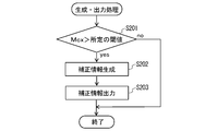
次に、情報処理装置10の出力部102による、補正情報の生成から出力までの処理の流れについて、図13に基づいて説明する。図13に示す処理は、取得部101によってモーメント情報が生成されたことをトリガとして、出力部102によって実行される処理である。
次に、情報処理装置10の出力部102による、補正情報の生成から出力までの処理の流れについて、図13に基づいて説明する。図13に示す処理は、取得部101によってモーメント情報が生成されたことをトリガとして、出力部102によって実行される処理である。
S201の処理では、出力部102は、取得部101により取得されたローリングモーメントMcxの大きさが所定の閾値より大きいか否かを判別する。ここでいう所定の閾値は、ローリングモーメントMcxが該所定の閾値より大きくなると、運動案内装置1の性能低下や故障を招くと想定される値であり、予め実験やシミュレーション等の結果に基づいて求めておくものとする。S201で否定判定された場合は、出力部102は、補正情報の生成処理及び出力処理を実行しない。一方、S201で肯定判定された場合は、出力部102は、S202へ進み、補正情報の生成処理及び補正処理を行う。
S202の処理では、出力部102は、先ず取得部101により取得されたローリングモーメントMcxの大きさに基づいて、補正情報を生成する。補正情報は、搬送物40をY軸方向へ移動させる際に用いられる制御パラメータを補正するための情報であり、具体的には、搬送物40をY軸方向へ移動させる際の目標速度を減速側へ補正するための情報である。ここで、目標速度を減速側へ補正するための情報を生成するにあたり、出力部102は、取得部101により取得されたローリングモーメントMcxと上記の所定の閾値との差ΔMcx(=(ローリングモーメントMcx)-(所定の閾値))を演算する。続いて、出力部102は、上記差ΔMcxに基づいて、補正値Δvを演算する。その際、補正値Δvは、図14に示すように、上記の差ΔMcxが大きくなるほど、大きな値になるように定められる。なお、図14に示すような相関は、予め実験やシミュレーションの結果に基づいて求めておき、関数式やマップの形態で情報処理装置10のメモリに記憶させておくようにしてもよい。出力部102は、上記した手順で求められた補正値Δvを補正情報として制御装置30側へ出力する。
S203の処理では、出力部102は、S202で生成された補正情報を、制御装置30へ出力する。
<NC装置側で実行される目標速度の補正処理>
次に、制御装置30側による、搬送物40をY軸方向へ移動させる際の目標速度の補正処理について、図15に基づいて説明する。図15に示す補正処理は、上記の出力部102から補正情報が出力されたことをトリガとして、制御装置30によって実行される処理である。
次に、制御装置30側による、搬送物40をY軸方向へ移動させる際の目標速度の補正処理について、図15に基づいて説明する。図15に示す補正処理は、上記の出力部102から補正情報が出力されたことをトリガとして、制御装置30によって実行される処理である。
S301の処理では、制御装置30は、上記の出力部102から出力された補正情報に基づいて、Y軸方向における搬送物40の目標速度を補正する。具体的には、制御装置30は、出力部102から出力された補正情報としての補正値Δvを現時点の目標速度から減算する方法によって、目標速度の補正を行う。
S302の処理では、制御装置30は、S301で求められた、補正後の目標速度に従って、搬送物40をY軸へ移動させるための第2アクチュエータ170を制御する。
以上述べたような運動案内装置1を備える位置決め装置20では、運動案内装置1のX軸まわりに働くローリングモーメントMcxが所定の閾値より大きくなった場合に、制御装置30は、出力部102から出力される補正情報を利用して、搬送物40をY軸方向へ移動させる際に用いられる目標速度を減速側へ補正することができる。その結果、ローリングモーメントMcxが過大になることに起因する、運動案内装置1の性能低下や故障を抑制することが可能になる。
なお、上記の出力部102は、ローリングモーメントMcxの大きさが上記の所定の閾値より大きくなったときに、上記したような補正情報とは別途に、搬送物40のY軸方向への移動に関するアラーム情報を制御装置30側へ出力するようにしてもよい。出力部102から制御装置30へアラーム情報が出力されると、制御装置30側において搬送物40の移動を停止させて、搬送物40の目標速度を調整したり、運動案内装置1を点検したりすることが可能となる。
また、前述の図2に示したように、運動案内装置1がリニアエンコーダ4を具備する構成においては、取得部101は、リニアエンコーダ4によって検出される第2キャリッジ120の位置毎にローリングモーメントMcxを取得してもよい。そして、出力部102は、第2キャリッジ120の各位置におけるローリングモーメントMcxを所定の閾値と比較することで、ローリングモーメントMcxが所定の閾値を上回る位置を特定するようにしてもよい。そして、出力部102は、前述の補正情報とともに、ローリングモーメントMcxが所定の閾値を上回った位置に関する情報を、制御装置30側へ出力してもよい。その場合、制御装置30側では、補正情報に基づく目標速度の補正処理に加え、上記の位置情報で特定される箇所の点検や補修等を行うことも可能になる。
なお、上記の実施形態では、インナーブロックが転動体を介して第1レール(又は第2レール)に組み付けられる構成を例に挙げたが、インナーブロックが第1レール(又は第2レール)に対してX軸方向へ相対的に摺動可能に組み付けられてもよい。また、上記の実施形態では、支障部材における中間部の厚さ及び幅をテーブル固定部及び背板固定部より小さくする構成を例に挙げたが、該中間部の厚さと幅の何れか一方のみをテーブル固定部及び背板固定部より小さくしてもよい。
1…運動案内装置、2a、2b、3a、3b…ひずみゲージ、10…情報処理装置、11…第1レール、12…第1キャリッジ、13…支承部材、13a…中間部、17…第1アクチュエータ、110…第2レール、120…第2キャリッジ、170…第2アクチュエータ
Claims (9)
- 第1軸方向に沿って延在する第1軌道部材と、前記第1軌道部材に対して第1軸方向に沿って相対的に移動可能に組み付けられる第1移動部材と、を有する第1案内部と、
前記第1案内部によって第1軸方向に沿って相対的に移動可能に支持され且つ第1軸に直交する第2軸方向に沿って延在する第2軌道部材と、前記第2軌道部材に対して第2軸方向に沿って相対的に移動可能に組み付けられ且つ搬送対象である搬送物を支持する第2移動部材と、有する第2案内部と、
を備える運動案内装置に適用されるモーメント検知装置であって、
第2軸方向における基端側の部位が前記第1移動部材に固定され且つ第2軸方向における先端側の部位が前記第1移動部材から突出しつつその突出部分に前記第2軌道部材が固定される支承部材と、
前記支承部材における前記第1移動部材が固定される部位と前記第2軌道部材が固定される部位との間の中間部に取り付けられ、該中間部の第2軸方向におけるひずみを検出するひずみゲージと、
前記運動案内装置により搬送物が第2軸方向の基端側から先端側へ移動される際の前記ひずみゲージの検出値に基づいて、該運動案内装置の第1軸まわりに働くローリングモーメントに関するモーメント情報を取得する取得部と、
を備える、
運動案内装置のモーメント検知装置。 - 前記支承部材は、前記第1移動部材が固定される部位及び前記第2軌道部材が固定される部位に比べ、前記中間部の剛性が小さくなるように形成される、
請求項1に記載の運動案内装置のモーメント検知装置。 - 前記支承部材は、前記第1移動部材が固定される部位及び前記第2軌道部材が固定される部位に比べ、前記中間部の厚さが薄くなるように形成される、
請求項2に記載の運動案内装置のモーメント検知装置。 - 前記支承部材は、前記第1移動部材が固定される部位及び前記第2軌道部材が固定される部位に比べ、前記中間部の幅が狭くなるように形成される、
請求項2又は3に記載の運動案内装置のモーメント検知装置。 - 前記中間部において前記ひずみゲージが取り付けられる位置は、前記第2移動部材の第2軸方向における可動範囲の基端側の端点よりも第2軸方向における基端側に配置される、
請求項2から4の何れか1項に記載の運動案内装置のモーメント検知装置。 - 前記第2軌道部材において前記支承部材と固定される部位より第2軸方向の基端側の部位には、前記運動案内装置により搬送物が第2軸方向の先端側から基端側へ移動される際の前記支承部材のひずみを規制するストッパが取り付けられる、
請求項1から5の何れか1項に記載の運動案内装置のモーメント検知装置。 - 前記モーメント検知装置は、
前記取得部により取得されたモーメント情報に基づいて、前記運動案内装置による搬送物の第2軸方向への移動に関わる所定の制御パラメータを補正するための補正情報を生成して、該搬送物の移動を制御するための制御装置側に出力する出力部を更に備える、
請求項1から6の何れか1項に記載の運動案内装置のモーメント検知装置。 - 前記出力部は、前記取得部によって取得されたモーメント情報に応じて、搬送物を第2軸方向へ移動させる際に用いられる目標速度を補正するための情報を生成し、その情報を前記補正情報として出力する、
請求項7に記載の運動案内装置のモーメント検知装置。 - 前記出力部は、前記取得部により取得された前記モーメント情報に基づいて、前記第1案内部に働くローリングモーメントが所定の閾値より大きいかを判別して、前記ローリングモーメントが前記所定の閾値より大きければ、前記搬送物の移動速度に関するアラーム情報を前記制御装置側へ出力する、
請求項7に記載の運動案内装置のモーメント検知装置。
Applications Claiming Priority (2)
| Application Number | Priority Date | Filing Date | Title |
|---|---|---|---|
| JP2017-083630 | 2017-04-20 | ||
| JP2017083630A JP2018179904A (ja) | 2017-04-20 | 2017-04-20 | 運動案内装置のモーメント検知装置 |
Publications (1)
| Publication Number | Publication Date |
|---|---|
| WO2018194097A1 true WO2018194097A1 (ja) | 2018-10-25 |
Family
ID=63856672
Family Applications (1)
| Application Number | Title | Priority Date | Filing Date |
|---|---|---|---|
| PCT/JP2018/016016 Ceased WO2018194097A1 (ja) | 2017-04-20 | 2018-04-18 | 運動案内装置のモーメント検知装置 |
Country Status (2)
| Country | Link |
|---|---|
| JP (1) | JP2018179904A (ja) |
| WO (1) | WO2018194097A1 (ja) |
Citations (4)
| Publication number | Priority date | Publication date | Assignee | Title |
|---|---|---|---|---|
| JPH07334245A (ja) * | 1994-06-13 | 1995-12-22 | Yotaro Hatamura | 超精密送り装置およびこれを用いたxyテ−ブル並びにテ−ブル移送装置 |
| JP2007263286A (ja) * | 2006-03-29 | 2007-10-11 | Nippon Thompson Co Ltd | 直動案内ユニットおよびそのひずみ検出方法 |
| JP2015218888A (ja) * | 2014-05-21 | 2015-12-07 | 日本精工株式会社 | 直動案内装置 |
| EP3078452A1 (en) * | 2015-04-09 | 2016-10-12 | Ideko, S. Coop | System for suppressing chatter in a machine tool |
-
2017
- 2017-04-20 JP JP2017083630A patent/JP2018179904A/ja active Pending
-
2018
- 2018-04-18 WO PCT/JP2018/016016 patent/WO2018194097A1/ja not_active Ceased
Patent Citations (4)
| Publication number | Priority date | Publication date | Assignee | Title |
|---|---|---|---|---|
| JPH07334245A (ja) * | 1994-06-13 | 1995-12-22 | Yotaro Hatamura | 超精密送り装置およびこれを用いたxyテ−ブル並びにテ−ブル移送装置 |
| JP2007263286A (ja) * | 2006-03-29 | 2007-10-11 | Nippon Thompson Co Ltd | 直動案内ユニットおよびそのひずみ検出方法 |
| JP2015218888A (ja) * | 2014-05-21 | 2015-12-07 | 日本精工株式会社 | 直動案内装置 |
| EP3078452A1 (en) * | 2015-04-09 | 2016-10-12 | Ideko, S. Coop | System for suppressing chatter in a machine tool |
Also Published As
| Publication number | Publication date |
|---|---|
| JP2018179904A (ja) | 2018-11-15 |
Similar Documents
| Publication | Publication Date | Title |
|---|---|---|
| JP5418272B2 (ja) | 工作機械の熱変位補正方法および熱変位補正装置 | |
| CN104908047B (zh) | 感知与外部环境的接触的机器人控制装置 | |
| KR102428628B1 (ko) | 가공 제어 시스템, 및 운동 안내 장치 | |
| US11067382B2 (en) | Three-dimensional coordinate measurement apparatus | |
| JP5816475B2 (ja) | 産業機械 | |
| EP2647477A1 (en) | Device for error correction for CNC machines | |
| TW201124230A (en) | Mechanical displacement compensation system of machine tool. | |
| JP4443891B2 (ja) | ステージ装置 | |
| JP2009184077A (ja) | 工作機械 | |
| KR20110004788A (ko) | 머니퓰레이터를 작동시키기 위한 방법 및 장치 | |
| EP2397815B1 (en) | Industrial machine | |
| TWI746777B (zh) | 工件搬送控制系統、及運動導引裝置 | |
| JP2018119840A (ja) | 測定装置 | |
| JP2014087880A (ja) | ボールねじの伸縮量に基づいて補正処理を実行するサーボ制御装置 | |
| JP2018179904A (ja) | 運動案内装置のモーメント検知装置 | |
| JP7141847B2 (ja) | 撓み量推定装置、ロボット制御装置、及び撓み量推定方法 | |
| JP2017223574A (ja) | 産業機械 | |
| US11472034B2 (en) | Lifetime estimation device for robot | |
| JP2021077118A (ja) | たわみ量算出装置及びプログラム | |
| JP2001287137A (ja) | 送りねじ装置の変位補正方法及び装置 | |
| JP2019158385A (ja) | 測定装置 | |
| JP2005299813A (ja) | 磁気支持装置 | |
| JPS60149909A (ja) | 三次元測定機の測定方法 |
Legal Events
| Date | Code | Title | Description |
|---|---|---|---|
| 121 | Ep: the epo has been informed by wipo that ep was designated in this application |
Ref document number: 18787128 Country of ref document: EP Kind code of ref document: A1 |
|
| NENP | Non-entry into the national phase |
Ref country code: DE |
|
| 122 | Ep: pct application non-entry in european phase |
Ref document number: 18787128 Country of ref document: EP Kind code of ref document: A1 |