WO2018193641A1 - 発電機能付きダンパ - Google Patents
発電機能付きダンパ Download PDFInfo
- Publication number
- WO2018193641A1 WO2018193641A1 PCT/JP2017/025674 JP2017025674W WO2018193641A1 WO 2018193641 A1 WO2018193641 A1 WO 2018193641A1 JP 2017025674 W JP2017025674 W JP 2017025674W WO 2018193641 A1 WO2018193641 A1 WO 2018193641A1
- Authority
- WO
- WIPO (PCT)
- Prior art keywords
- rod
- damper
- power generation
- generation function
- cylinder
- Prior art date
- Legal status (The legal status is an assumption and is not a legal conclusion. Google has not performed a legal analysis and makes no representation as to the accuracy of the status listed.)
- Ceased
Links
Images





Classifications
-
- F—MECHANICAL ENGINEERING; LIGHTING; HEATING; WEAPONS; BLASTING
- F16—ENGINEERING ELEMENTS AND UNITS; GENERAL MEASURES FOR PRODUCING AND MAINTAINING EFFECTIVE FUNCTIONING OF MACHINES OR INSTALLATIONS; THERMAL INSULATION IN GENERAL
- F16F—SPRINGS; SHOCK-ABSORBERS; MEANS FOR DAMPING VIBRATION
- F16F15/00—Suppression of vibrations in systems; Means or arrangements for avoiding or reducing out-of-balance forces, e.g. due to motion
- F16F15/02—Suppression of vibrations of non-rotating, e.g. reciprocating systems; Suppression of vibrations of rotating systems by use of members not moving with the rotating systems
-
- F—MECHANICAL ENGINEERING; LIGHTING; HEATING; WEAPONS; BLASTING
- F16—ENGINEERING ELEMENTS AND UNITS; GENERAL MEASURES FOR PRODUCING AND MAINTAINING EFFECTIVE FUNCTIONING OF MACHINES OR INSTALLATIONS; THERMAL INSULATION IN GENERAL
- F16F—SPRINGS; SHOCK-ABSORBERS; MEANS FOR DAMPING VIBRATION
- F16F15/00—Suppression of vibrations in systems; Means or arrangements for avoiding or reducing out-of-balance forces, e.g. due to motion
- F16F15/02—Suppression of vibrations of non-rotating, e.g. reciprocating systems; Suppression of vibrations of rotating systems by use of members not moving with the rotating systems
- F16F15/03—Suppression of vibrations of non-rotating, e.g. reciprocating systems; Suppression of vibrations of rotating systems by use of members not moving with the rotating systems using magnetic or electromagnetic means
-
- F—MECHANICAL ENGINEERING; LIGHTING; HEATING; WEAPONS; BLASTING
- F16—ENGINEERING ELEMENTS AND UNITS; GENERAL MEASURES FOR PRODUCING AND MAINTAINING EFFECTIVE FUNCTIONING OF MACHINES OR INSTALLATIONS; THERMAL INSULATION IN GENERAL
- F16F—SPRINGS; SHOCK-ABSORBERS; MEANS FOR DAMPING VIBRATION
- F16F15/00—Suppression of vibrations in systems; Means or arrangements for avoiding or reducing out-of-balance forces, e.g. due to motion
- F16F15/02—Suppression of vibrations of non-rotating, e.g. reciprocating systems; Suppression of vibrations of rotating systems by use of members not moving with the rotating systems
- F16F15/04—Suppression of vibrations of non-rotating, e.g. reciprocating systems; Suppression of vibrations of rotating systems by use of members not moving with the rotating systems using elastic means
-
- F—MECHANICAL ENGINEERING; LIGHTING; HEATING; WEAPONS; BLASTING
- F16—ENGINEERING ELEMENTS AND UNITS; GENERAL MEASURES FOR PRODUCING AND MAINTAINING EFFECTIVE FUNCTIONING OF MACHINES OR INSTALLATIONS; THERMAL INSULATION IN GENERAL
- F16F—SPRINGS; SHOCK-ABSORBERS; MEANS FOR DAMPING VIBRATION
- F16F7/00—Vibration-dampers; Shock-absorbers
- F16F7/01—Vibration-dampers; Shock-absorbers using friction between loose particles, e.g. sand
-
- H—ELECTRICITY
- H02—GENERATION; CONVERSION OR DISTRIBUTION OF ELECTRIC POWER
- H02N—ELECTRIC MACHINES NOT OTHERWISE PROVIDED FOR
- H02N15/00—Holding or levitation devices using magnetic attraction or repulsion, not otherwise provided for
Definitions
- the present invention relates to a damper with a power generation function.
- the damper of Patent Document 1 includes a cylinder, a piston that is movably inserted into the cylinder, and a rod that is movably inserted into the cylinder and connected to the piston.
- the damper includes an extension side chamber and a pressure side chamber provided in the cylinder, a damping passage and a pump passage that communicate the extension side chamber and the pressure side chamber in parallel, and a fluid that is provided in the middle of the damping passage.
- a resistance element that gives resistance to the flow and a bidirectional discharge type pump provided in the middle of the pump passage are provided.
- the damper pump is driven by a motor. When the damper is driven by a motor, the damper can send fluid from the expansion side chamber to the compression side chamber or from the compression side chamber to the expansion side chamber.
- Patent Document 1 discloses that each of the pump and motor of the damper functions as a fluid motor and a generator, and the generator can be driven by the flow of fluid passing through the pump passage to generate power. Yes.
- this damper has a small flow rate of fluid flowing through the pump passage, the pump and the motor are difficult to rotate, and the amount of power generated by the motor functioning as a generator is small. For this reason, this damper cannot generate electricity well.
- the present invention has been made in view of the above-described conventional situation, and it is an object to be solved to provide a damper with a power generation function that can generate a damping force and can generate electric power satisfactorily.
- the damper with a power generation function of the present invention includes a case, a rod, magnet particles, and a coil part.
- the case protrudes to the outside with a rod that can reciprocate in the axial direction or can rotate about the axis.
- the magnet particles have the characteristics of a permanent magnet, and a plurality of magnet particles are filled in the case.
- the direction of the magnetic force lines formed by the plurality of magnet particles changes in accordance with the reciprocating movement of the rod or the rotation around the axis, so that the number of magnetic force lines penetrating the coil portion changes to generate an induced electromotive force.
- the magnet particles of the damper with a power generation function of the present invention can have elasticity.
- a coil portion can be arranged in the rod.
- a permanent magnet may be disposed in the rod, and the coil portion may be disposed in the case.
- the damper with a power generation function of the present invention may be provided in a case, and may include a piston that is connected to the rod and reciprocates with the rod.
- a permanent magnet may be disposed in a piston, and a coil portion may be disposed in a case.
- a coil portion can be arranged in the piston.
- the damper with a power generation function of the present invention may be provided in a case, connected to a rod rotatable around an axis, and provided with a rotor that rotates in the case together with the rod.
- FIG. It is a schematic diagram of the magnet particle with which the case of the damper with an electric power generation function of Embodiment 1 is filled.
- frequency the speed for reciprocating the rod and piston of the damper with power generation function of the first embodiment in the direction of the central axis of the case
- the magnitude of the induced electromotive force generated in the coil portion It is a graph (graph) which shows change, (A) shows change with respect to time of the size of the induced electromotive force of the 1st cycle, and (B) shows change with respect to time of the size of the induced electromotive force of the 10th cycle. Indicates.
- (A) shows the magnitude of the induced electromotive force generated in the coil section with respect to the frequency
- (B) shows the power generated based on the induced electromotive force generated in the coil section with respect to the frequency.
- FIG. 10 is a cross-sectional view showing a damper according to a sixth embodiment, where (A) is a cross-sectional view in the central axis direction of the rotor, and (B) is a cross-sectional view along AA in FIG. 10 (A).
- (A) is the elements on larger scale which show the state of the magnet particle which contact
- (B) is an electric power generation function which does not have a piston. It is a partial enlarged view which shows the state of the magnet particle contact
- the damper 1 with the power generation function of the first embodiment includes a cylinder 10, a piston 30, a rod 50, a pair of rod guides 70, a plurality of magnet particles 90, and a coil unit 20. It has.
- the cylinder 10 has a cylindrical shape with both ends open.
- the piston 30 has a central portion 30A and both end portions 30B.
- the central portion 30A has a cylindrical shape.
- Both end portions 30B have a truncated cone shape whose outer diameter gradually decreases in a direction away from both end surfaces of the central portion 30A.
- a predetermined gap is formed between the outer peripheral surface of the piston 30 and the inner peripheral surface of the cylinder 10.
- the piston 30 is disposed in the cylinder 10.
- the rod 50 has a cylindrical shape.
- the rod 50 is continuous with the tip of both end portions 30 ⁇ / b> B of the piston 30 and extends in both directions of the piston 30.
- the rod 50 extends in the direction of the central axis of the cylinder 10 and protrudes from the open end portions 10 ⁇ / b> A at both ends of the cylinder 10 to the outside of the cylinder 10. That is, the piston 30 is connected to the rod 50.
- the rod guide 70 has a disk shape having a flange 70B on the outer periphery, and is connected to each open end 10A so as to close each open end 10A at both ends of the cylinder 10.
- These rod guides 70 are provided with through holes 70 ⁇ / b> A penetrating in the disc-like thickness direction at the disc-like center.
- the inner diameter of the through hole 70 ⁇ / b> A is slightly larger than the outer diameter of the rod 50.
- the through hole 70 ⁇ / b> A penetrates in the direction of the central axis of the cylinder 10 in a state where the rod guide 70 is fixed to the respective open end portions 10 ⁇ / b> A at both ends of the cylinder 10.
- the rod 50 is inserted into the through holes 70A of the rod guides 70 so as to be reciprocally movable. Both the rod 50 and the piston 30 can reciprocate within the cylinder 10 in the direction of the center axis of the cylinder 10.
- the cylinder 10, the piston 30, the rod 50, and the pair of rod guides 70 are nonmagnetic materials.
- the plurality of magnet particles 90 have a spherical shape as shown in FIG.
- These magnet particles 90 are elastic bodies made of silicone rubber, which is an elastomer having a durometer type A hardness (hereinafter referred to as hardness) of 60.
- the magnet particles 90 contain neodymium (Nd) particles 90A.
- the amount of neodymium (Nd) particles 90A contained in the magnet particles 90 is about 60 wt. % (17.78 vol.%).
- Neodymium (Nd) particles 90A have magnetism. That is, the magnet particle 90 has magnetism and elasticity.
- These magnet particles 90 thus formed are magnetized and have a magnetic force. That is, these magnet particles 90 have the characteristics of permanent magnets.
- the magnet particles 90 are filled in a space surrounded by the cylinder 10 and the pair of rod guides 70 (that is, in the cylinder 10) at a filling rate of 60%.
- the filling rate is expressed by the following equation (1).
- the filling volume is the volume of the space in which the magnet particles 90 are filled.
- the coil portion 20 is a metal wire whose surface is covered with an insulating film, which is coaxially wound a plurality of times and bundled in a cylindrical shape having a predetermined width in the radial direction and an inner diameter slightly larger than the outer diameter of the cylinder 10 It is. Further, both ends of the metal wire of the coil part 20 are drawn out, and a current generated based on the induced electromotive force generated in the coil part 20 is supplied to an electric device or the like provided outside the damper 1 with the power generation function. (Not shown).
- the coil portion 20 is disposed on the outer peripheral surface of the cylinder 10 so that the cylindrical inner side of the coil portion 20 inserts the cylinder 10 and is along the outer peripheral surface of the cylinder 10.
- the magnet particles 90 pass through a predetermined gap between the outer peripheral surface of the piston 30 and the inner peripheral surface of the cylinder 10. Then move. At this time, between the inner peripheral surface of the cylinder 10 and the magnet particles 90 in contact with the inner peripheral surface of the cylinder 10, between the adjacent magnet particles 90, and the outer peripheral surfaces of the rod 50 and the piston 30, and the rod 50 and the piston 30. A frictional force is generated between the magnet particles 90 and the outer peripheral surface of the magnet particles 90. Further, the magnet particles 90 positioned on the moving side of the piston 30 are crushed by the piston 30.
- the piston 30 is pushed back by the elastic repulsive force generated by the magnet particles 90 crushed by the piston 30. That is, the damper 1 with the power generation function generates a damping force based on the frictional force thus generated and the elastic repulsive force.
- a pressing force F is applied to the magnet particle 90.
- the direction of the pressing force F is a direction perpendicular to the inclined surfaces of the both end portions 30B.
- the pressing force F can be divided into a component force F1 in the direction of the center axis of the cylinder 10 and a component force F2 in a direction away from the center axis of the cylinder 10.
- the magnet particles 90 crushed by the piston 30 move in a direction away from the center axis of the cylinder 10 by the component force F2.
- the rod 550 moves in the central axis direction of the cylinder 10 when the piston 550 is not provided as in the damper 61 with a power generation function shown in FIG. 11B, the rod 550 contacts the outer peripheral surface of the rod 550.
- the magnet particles 90 roll due to the frictional force generated between the magnet particles 90 and the outer peripheral surface of the rod 550 or move together with the rod 550. That is, when the piston is not provided, the magnet particle 90 is not crushed by the rod 550 that moves in the central axis direction of the cylinder 10. For this reason, no pressing force is applied to the magnet particles 90, and the flow of the magnet particles 90 is smaller than when a piston is provided. That is, by providing the piston 30, the magnet particles 90 filled in the cylinder 10 can be more actively flowed.
- the induced electromotive force is generated in the entire region where the rod 50 and the piston 30 move in the direction of the central axis of the cylinder 10.
- the waveforms of the induced electromotive force generated in the first period and the tenth period are different from each other. This is because each time the rod 50 and the piston 30 are repeatedly reciprocated in the central axis direction of the cylinder 10, the direction of the magnetic force lines of the plurality of magnet particles 90 changes, and therefore the number of magnetic force lines penetrating the coil portion 20 is changed. This is thought to be because the way is different.
- FIGS. graphs showing changes with time in the magnitude of the induced electromotive force generated in the coil portion 20 when the rod 50 and the piston 30 of the damper 1 with the power generation function are set to a frequency of 5 Hz are shown in FIGS. ). Specifically, (A) shows the change of the magnitude of the induced electromotive force in the first period with respect to time, and (B) shows the change of the magnitude of the induced electromotive force in the 10th period with respect to time.
- an induced electromotive force is generated in the entire region in which the rod 50 and the piston 30 move in the central axis direction of the cylinder 10.
- size of an induced electromotive force is large compared with the case where the rod 50 and piston 30 are frequency 1Hz. This is considered to be because the magnet particles 90 filled in the cylinder 10 flow more actively than in the case of a frequency of 1 Hz, and the number of lines of magnetic force penetrating through the coil portion 20 changes more actively.
- the waveforms of the induced electromotive force generated in the first period and the tenth period are different from each other.
- the frequency is generated based on the induced electromotive force generated in the coil unit 20 and the induced electromotive force generated in the coil unit 20.
- the amount of power that has been increased This is because as the frequency of the rod 50 and the piston 30 increases, the magnet particles 90 filled in the cylinder 10 flow more actively, and the number of magnetic lines penetrating the coil portion 20 changes more actively. It is thought that.
- the damper 1 with the power generation function is configured such that when the rod 50 and the piston 30 reciprocate in the central axis direction of the cylinder 10, the magnet particles 90 filled in the cylinder 10 move in the cylinder 10 to thereby reduce the damping force. Is generated. Further, when the direction of the magnetic force lines formed by the plurality of magnet particles 90 moving in the cylinder 10 changes, the number of magnetic force lines penetrating through the coil portion 20 changes. As a result, an induced electromotive force is generated in the coil portion 20. That is, the damper 1 with the power generation function generates power.
- the damper 1 with the power generation function of the present invention can generate a good damping force and can generate electric power satisfactorily.
- the magnet particle 90 of the damper 1 with a power generation function has elasticity. For this reason, when the rod 50 reciprocates in the axial direction or rotates around the axis, the plurality of magnet particles 90 filled in the cylinder 10 are elastically deformed. The damper 1 with a power generation function generates a damping force by the frictional force between the magnet particles 90 generated at this time and the elastic repulsion force of the magnet particles 90. In addition, since the magnet particles 90 have elasticity, the magnet particles 90 are unlikely to be burned by the elastic deformation of the adjacent magnet particles 90 with each other. For this reason, it is difficult for the damper 1 with a power generation function to prevent the rod 50 from reciprocating in the axial direction or rotating around the axis.
- the damper 1 with the power generation function is disposed in the cylinder 10 and includes a piston 30 that is connected to the rod 50 and reciprocates together with the rod 50. For this reason, the damper 1 with a power generation function can flow the magnet particles 90 filled in the cylinder 10 by the piston 30 more actively. For this reason, in the damper 1 with the power generation function, the magnetic lines of force of the magnet particles 90 pass through the coil portion 20 more actively. Thereby, the damper 1 with a power generation function is more likely to change the number of lines of magnetic force penetrating through the coil portion 20 more actively, and a large induced electromotive force is likely to be generated in the coil portion 20.
- the damper 11 with the power generation function of the second embodiment is different from the first embodiment in that a magnet 40 that is a permanent magnet is provided on the piston 130.
- Other configurations are the same as those of the first embodiment, the same configurations are denoted by the same reference numerals, and detailed description thereof is omitted.
- the damper 11 with a power generation function is provided with a magnet 40 in a piston 130.
- the magnet 40 has the characteristics of a permanent magnet, for example, is formed in a columnar shape, and the central axis is disposed in the piston 130 coaxially with the central axis of the rod 50 and the piston 130.
- the magnet 40 is magnetized so that, for example, one end of the columnar shape has an N pole and the other end has an S pole.
- the damper 11 with a power generation function formed in this way passes through a predetermined gap between the outer peripheral surface of the piston 130 and the inner peripheral surface of the cylinder 10. Then move. At this time, between the inner peripheral surface of the cylinder 10 and the magnet particles 90 contacting the inner peripheral surface of the cylinder 10, between the adjacent magnet particles 90, and the outer peripheral surfaces of the rod 50 and the piston 130 and the rod 50 and the piston 130. A frictional force is generated between the magnet particles 90 and the outer peripheral surface of the magnet particles 90. Further, the magnet particles 90 located on the moving side of the piston 130 are crushed by the piston 130.
- the piston 130 is pushed back by the elastic repulsive force generated by the magnet particles 90 crushed by the piston 130. That is, the damper 11 with the power generation function generates a damping force based on the frictional force thus generated and the elastic repulsive force.
- the damper 11 with the power generation function is configured such that when the rod 50 and the piston 130 reciprocate in the central axis direction of the cylinder 10, the magnet particle 90 filled in the cylinder 10 moves in the cylinder 10 to thereby reduce the damping force. Is generated. Further, when the direction of the magnetic force lines formed by the plurality of magnet particles 90 moving in the cylinder 10 changes, the number of magnetic force lines penetrating through the coil portion 20 changes. As a result, an induced electromotive force is generated in the coil portion 20. That is, the damper 11 with the power generation function generates power.
- the damper 11 with the power generation function of the present invention can also generate a good damping force and generate electric power satisfactorily.
- the damper 11 with the power generation function aligns the direction of the magnetic particles 90 so that the direction of the magnetic lines of force of the magnet particles 90 filled in the cylinder 10 by the magnets 40 in the piston 130 is aligned,
- the magnet particles 90 filled in can be more actively flowed.
- the damper 11 with the power generation function is more likely to change more actively the number of magnetic lines of force that pass through the coil part 20, and a large induced electromotive force is generated in the coil part 20 arranged in the cylinder 10. It becomes easy.
- the damper 21 with the power generation function of the third embodiment is different from the first and second embodiments in that a coil portion 120 is provided in the piston 230.
- Other configurations are the same as those of the first and second embodiments, and the same configurations are denoted by the same reference numerals and detailed description thereof is omitted.
- the coil portion 120 is provided in the piston 230. Specifically, as shown in FIG. 7, the coil portion 120 is arranged in the piston 230 so that the central axis of the cylindrical coil portion 120 is coaxial with the central axis of the rod 150 and the piston 230. Yes. Further, both ends of the metal wire drawn from the coil part 120 are drawn to the outside of the damper 21 with the power generation function via the inner side of one side of the rod 150, and the induced electromotive force generated in the coil part 120 is The electric current generated based on this is supplied to an electric device or the like provided outside the damper 21 with the power generation function (not shown).
- the magnetic material 90 passes through a predetermined gap between the outer peripheral surface of the piston 230 and the inner peripheral surface of the cylinder 10. Then move. At this time, between the inner peripheral surface of the cylinder 10 and the magnet particles 90 in contact with the inner peripheral surface of the cylinder 10, between the adjacent magnet particles 90, and the outer peripheral surfaces of the rod 150 and the piston 230, and the rod 150 and the piston 230. A frictional force is generated between the magnet particles 90 in contact with the outer peripheral surface. Further, the magnet particles 90 located on the moving side of the piston 230 are crushed by the piston 230.
- the piston 230 is pushed back by the elastic repulsive force generated by the magnet particles 90 crushed by the piston 230. That is, the damper 21 with the power generation function generates a damping force based on the frictional force thus generated and the elastic repulsion force.
- the damper 21 with the power generation function is configured such that when the rod 150 and the piston 230 reciprocate in the direction of the central axis of the cylinder 10, the magnet particles 90 filled in the cylinder 10 move in the cylinder 10 to reduce the damping force. Is generated. Further, when the direction of the magnetic force lines formed by the plurality of magnet particles 90 moving in the cylinder 10 changes, the number of magnetic force lines penetrating the coil part 120 changes. As a result, an induced electromotive force is generated in the coil unit 120. That is, the damper 21 with the power generation function generates power.
- the damper 21 with the power generation function of the present invention also generates a good damping force and can generate power well.
- the coil part 120 is disposed in the piston 230.
- the position with respect to the magnet particle 90 in the cylinder 10 can change reliably the coil part 120 arrange
- the damper 21 with a power generation function the magnetic lines of force of the magnet particles 90 surely pass through the coil part 120.
- the damper 21 with a power generation function easily changes the number of lines of magnetic force penetrating through the coil part 120, and a large induced electromotive force is easily generated in the coil part 120.
- the damper 21 with the power generation function can actively flow the magnet particles 90 filled in the cylinder 10 by the piston 230, a large induced electromotive force is easily generated in the coil portion 120.
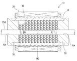
- the damper 31 with the power generation function of the fourth embodiment is different from the first to third embodiments in that a piston is not provided and a magnet 140, which is a permanent magnet, is provided in the rod 250. To do.
- Other configurations are the same as those in the first to third embodiments. The same configurations are denoted by the same reference numerals, and detailed description thereof is omitted.
- the damper 31 with a power generation function includes a magnet 140 in a rod 250.
- the magnet 140 has the characteristics of a permanent magnet, for example, is formed in a columnar shape, and the central axis is disposed in the rod 250 coaxially with the central axis of the rod 250.
- the magnet 140 is magnetized so that, for example, one end of the columnar shape has an N pole and the other end has an S pole.
- the magnetic particle 90 moves in a predetermined gap between the outer peripheral surface of the rod 250 and the inner peripheral surface of the cylinder 10.
- the magnet particles 90 that come into contact with the outer peripheral surface of the rod 250 move together with the rod 250 by the frictional force generated between the rod 250 and the outer peripheral surface.
- a frictional force is also generated between the inner peripheral surface of the cylinder 10 and the magnet particles 90 in contact with the inner peripheral surface of the cylinder 10 and between adjacent magnet particles 90. That is, the damper 31 with the power generation function generates a damping force based on the frictional force thus generated.
- the number of lines of magnetic force formed by the plurality of magnet particles 90 penetrating through the coil portion 20 changes as the direction of the lines of magnetic force formed by the plurality of magnet particles 90 changes as the rod 250 reciprocates. Therefore, an induced electromotive force is generated in the coil unit 20. That is, the damper 31 with the power generation function generates power with the coil unit 20.
- the damper 31 with the power generation function generates a damping force by moving the magnet particles 90 filled in the cylinder 10 in the cylinder 10 when the rod 250 reciprocates in the central axis direction of the cylinder 10. . Further, when the direction of the magnetic force lines formed by the plurality of magnet particles 90 moving in the cylinder 10 changes, the number of magnetic force lines penetrating through the coil portion 20 changes. As a result, an induced electromotive force is generated in the coil portion 20. That is, the damper 31 with a power generation function generates power.
- the damper 31 with the power generation function of the present invention can also generate a good damping force and can generate electric power satisfactorily.
- the damper 31 with the power generation function the magnet 140 is disposed in the rod 250, and the coil portion 20 is disposed in the cylinder 10.
- the damper 31 with a power generation function can align the direction of the magnet particles 90 so that the direction of the magnetic lines of force of the magnet particles 90 is aligned by the magnet 140 in the rod 250.
- the number of magnetic lines of force that pass through the coil portion 20 changes in the damper 31 with the power generation function, so that a large induced electromotive force is easily generated in the coil portion 20 disposed in the cylinder 10.
- the damper 41 with the power generation function of the fifth embodiment is different from the first to fourth embodiments in that the piston is not provided and the coil portion 220 is provided in the rod 350.
- Other configurations are the same as those of the first to fourth embodiments. The same configurations are denoted by the same reference numerals, and detailed description thereof is omitted.
- a coil part 220 is provided in a rod 350.
- the coil portion 220 is disposed in the rod 350 so that the central axis of the coil portion 220 having a cylindrical shape is coaxial with the central axis of the rod 350.
- both ends of the metal wire drawn from the coil part 220 are drawn to the outside of the damper 41 with the power generation function via the inner side of one side of the rod 350, and the induced electromotive force generated in the coil part 220 is The current generated based on this is configured to be supplied to an electric device or the like provided outside the damper 41 with the power generation function (not shown).
- the magnetic particle 90 moves in a predetermined gap between the outer peripheral surface of the rod 350 and the inner peripheral surface of the cylinder 10.
- the magnet particles 90 that abut on the outer peripheral surface of the rod 350 move together with the rod 350 by the frictional force generated between the rod 350 and the outer peripheral surface.
- a frictional force is also generated between the inner peripheral surface of the cylinder 10 and the magnet particles 90 in contact with the inner peripheral surface of the cylinder 10 and between adjacent magnet particles 90. That is, the damper 41 with the power generation function generates a damping force based on the frictional force thus generated.
- the damper 41 with the power generation function generates a damping force by moving the magnet particles 90 filled in the cylinder 10 in the cylinder 10 when the rod 350 reciprocates in the central axis direction of the cylinder 10. . Further, when the direction of the magnetic force lines formed by the plurality of magnet particles 90 moving in the cylinder 10 changes, the number of magnetic force lines penetrating through the coil part 220 changes. As a result, an induced electromotive force is generated in the coil unit 220. That is, the damper 41 with the power generation function generates power.
- the damper 41 with the power generation function of the present invention also generates a good damping force and can generate electric power satisfactorily.
- the damper 41 with a power generation function has a coil portion 220 disposed in a rod 350. For this reason, the position of the coil part 220 disposed in the rod 350 with respect to the magnet particle 90 in the cylinder 10 can be reliably changed. For this reason, in the damper 41 with a power generation function, the magnetic lines of force of the magnet particles 90 surely pass through the coil part 220. Thereby, the damper 41 with a power generation function easily changes the number of lines of magnetic force penetrating through the coil part 220, and a large induced electromotive force is easily generated in the coil part 220.
- the damper 51 with the power generation function of the sixth embodiment includes the shape of the cylinder 110, the shape of the rod guide 170, the rod 450 and the rotor 35 of the cylinder 110 around the axis.
- the point of rotation around the central axis, the shape of the coil part 320, the arrangement of the coil part 320 with respect to the cylinder 110, and the like are different from those of the first to fifth embodiments.
- Other configurations are the same as those of the first to fifth embodiments. The same configurations are denoted by the same reference numerals, and detailed description thereof is omitted.
- the cylinder 110 has a cylindrical shape with both ends opened.
- the first rod guide 171 which is the rod guide 170, has a disc shape, and is connected to the cylinder 110 so that one end surface of the cylinder 110 is brought into contact with the other surface to close one side of the cylinder 110.
- a first through hole 171A is provided at the center of the disk shape of the first rod guide 171 so as to penetrate in the thickness direction.
- the first through hole 171A on the other surface side of the first rod guide 171 is formed with a first abutting portion 171B extending in a flat plate shape inward from the inner peripheral surface of the first through hole 171A.
- the inner diameter of the first abutting portion 171B is slightly larger than the outer diameter of the rod 450 described later.
- a shield bearing 60 is fitted in the first through hole 171A, and one surface of the shield bearing 60 is in contact with one surface of the first abutting portion 171B.
- the second rod guide 172 which is the rod guide 170, has a disk shape and is connected to the cylinder 110 so that one surface abuts the other end surface of the cylinder 110 and the other side of the cylinder 110 is closed.
- a second through hole 172A is provided at the center of the disc shape of the second rod guide 172 so as to penetrate in the thickness direction.
- a second abutting portion 172B extending in a flat plate shape inward from the inner peripheral surface of the second through hole 172A is formed at an intermediate portion of the second through hole 172A penetrating in the plate thickness direction.
- the inner diameter of the second abutting portion 172B is slightly larger than the outer diameter of the rod 450.
- the inner diameter of the second through hole 172A is larger than the distance from one surface of the second attaching portion 172B to one surface of the second rod guide 172 (hereinafter referred to as one side of the second through hole 172A).
- the distance from the other surface of the second attaching portion 172B to the other surface of the second rod guide 172 (hereinafter referred to as the other side of the second through hole 172A) is smaller.
- the shield bearing 60 is fitted on the other side of the second through hole 172A, and one surface of the shield bearing 60 is in contact with the other surface of the second abutting portion 172B.
- the third rod guide 173 which is the rod guide 170 has a disk shape thicker than the first rod guide 171 and the second rod guide 172.
- the third rod guide 173 has a disc-shaped outer diameter that is substantially the same as the inner diameter of the cylinder 110.
- the third rod guide 173 has one disk-shaped surface abutted against the other surface of the first rod guide 171 and is fitted into one open end 110 ⁇ / b> A of the cylinder 110 and coupled to the first rod guide 171. Yes.
- a third through hole 173A is provided in the center of the disc shape of the third rod guide 173 so as to penetrate in the thickness direction.
- the third through hole 173A on the other surface side of the third rod guide 173 is formed with a third abutting portion 173B extending in a flat plate shape inward from the inner peripheral surface of the third through hole 173A.
- the inner diameter of the third abutting portion 173B is slightly larger than the outer diameter of the first end portion 35B of the rotor 35 described later.
- the 4th rod guide 174 which is the rod guide 170 is a disk shape thicker than the 1st rod guide 171 and the 2nd rod guide 172, and thinner than the 3rd rod guide 173.
- the fourth rod guide 174 has a disc-shaped outer diameter that is substantially the same as the inner diameter of the cylinder 110.
- the fourth rod guide 174 is connected to the second rod guide 172 by fitting the other disc-shaped surface into one surface of the second rod guide 172 and fitting into the other opening end 110A of the cylinder 110. Yes.
- a fourth through hole 174A is provided in the disc-shaped center of the fourth rod guide 174 so as to penetrate in the thickness direction.
- the fourth through hole 174A on one surface side of the fourth rod guide 174 is formed with a fourth abutting portion 174B extending in a flat plate shape inward from the inner peripheral surface of the fourth through hole 174A.
- the inner diameter of the fourth abutting portion 174B is slightly larger than the outer diameter of the second end portion 35C of the rotor 35.
- the rotor 35 has a central portion 35A, a first end portion 35B, and a second end portion 35C.
- the central portion 35A is disposed between the other surface of the third rod guide 173 and one surface of the fourth rod guide 174, and the cross-sectional shape perpendicular to the central axis of the cylinder 110 is a square shape ( (See FIG. 10B). Further, a ridge (hereinafter referred to as a ridge) is formed between two adjacent surfaces of the four surfaces forming the square shape.
- a first plane 35D orthogonal to the central axis of the cylinder 110 is formed at each end of the central portion 35A in the central axis direction of the cylinder 110.
- the first end portion 35B and the second end portion 35C each have a cylindrical shape and extend in opposite directions from the centers of the two first planes 35D of the central portion 35A.
- a second flat surface 35E perpendicular to the central axis of the cylinder 110 is formed on the side of the first end portion 35B and the second end portion 35C away from the central portion 35A.
- the rod 450 extends from the center of the second plane 35E of the first end 35B and the second end 35C. That is, the rotor 35 is connected to the rod 450.
- the rod 450 and the first end 35B and the second end 35C are coaxial with each other.
- the rotor 35 is disposed in the cylinder 110.
- the rod 450 is rotatably connected to the first rod guide 171 and the second rod guide 172 via shield bearings 60 fitted in the first rod guide 171 and the second rod guide 172, respectively.
- Each of the first end portion 35B and the second end portion 35C includes the third abutting portion 173B of the third through hole 173A of the third rod guide 173 and the fourth through hole 174A of the fourth rod guide 174.
- the abutting portion 174B is rotatably inserted.
- a thrust bearing 80 is disposed inside the third through hole 173A of the third rod guide 173, and the second flat surface 35E of the first end portion 35B inserted through the third abutting portion 173B. And the other surface of the first rod guide 171 sandwich the thrust bearing 80.
- a thrust bearing 80 is also arranged inside the fourth through hole 174A of the fourth rod guide 174, and the second flat surface 35E of the second end 35C inserted into the fourth abutting portion 174B and the second rod.
- a thrust bearing 80 is sandwiched between one surface of the guide 172.
- the coil part 320 is formed by winding a metal wire whose surface is covered with an insulating film a plurality of times coaxially, having a predetermined width in the radial direction, and bundling in an annular shape.
- four coil portions 320 are arranged on the outer peripheral surface of the cylinder 110 so that one end of each annular shape is along the outer peripheral surface of the cylinder 110.
- the damper 51 with the power generation function generates a damping force in a direction opposite to the direction in which the rotor 35 rotates based on the frictional force thus generated and the elastic repulsive force.
- the magnetic lines of force formed by the plurality of magnet particles 90 penetrate through the four coil portions 320 by changing the direction of the lines of magnetic force formed by the plurality of magnet particles 90 as the rod 450 and the rotor 35 rotate. Since the number to be changed changes, an induced electromotive force is generated in these coil portions 320. That is, the damper 51 with the power generation function generates power with the four coil portions 320.
- the damper 51 with the power generation function is configured such that when the rod 450 and the rotor 35 rotate around the central axis of the cylinder 110, the magnet particles 90 filled in the cylinder 110 move in the cylinder 110, thereby reducing the damping force. Is generated. Further, when the direction of the magnetic force lines formed by the plurality of magnet particles 90 moving in the cylinder 110 changes, the number of magnetic force lines penetrating through the four coil portions 320 changes. As a result, an induced electromotive force is generated in the coil section 320. That is, the damper 51 with the power generation function generates power.
- the damper 51 with a power generation function of the present invention can also generate a good damping force and can generate power well.
- the damper 51 with a power generation function is disposed in the cylinder 110, is connected to a rod 450 that is rotatable around the central axis of the cylinder 110, and includes a rotor 35 that rotates in the cylinder 110 together with the rod 450. For this reason, when the rod 450 and the rotor 35 rotate around the central axis of the cylinder 110, the magnet particles 90 filled in the cylinder 110 flow in the direction in which the rod 450 and the rotor 35 rotate. Thereby, the damper 51 with a power generation function can generate an induced electromotive force in the coil part 320 while generating a damping force in a direction opposite to the direction in which the rod 450 and the rotor 35 rotate.
- the present invention is not limited to the first to sixth embodiments described with reference to the above description and the drawings.
- the following embodiments are also included in the technical scope of the present invention.
- the coil portion is provided on the outer peripheral surface of the cylinder, the piston, and the rod, but the coil portion may be provided on the outer peripheral surface of the cylinder, the rod, and the piston.
- the magnet particle is an elastic body made of silicone rubber which is an elastomer having a hardness of 60, but other materials may be used as long as they have magnetism. May be used in combination. Also, the hardness of the magnet particles may be about 40 to 90. Moreover, the material which does not elastically deform may be sufficient.
- the size of the plurality of magnet particles filled in the cylinder is uniform, but magnet particles having a plurality of types of particle diameters may be filled in the cylinder.
- neodymium (Nd) particles are contained in the magnet particles, but other materials may be contained as long as they are magnetic materials. Moreover, you may contain these materials in combination.
- the rod protrudes from the cylinder opening end to the outside of the cylinder. However, the rod protrudes from one of the pistons (rotors), and the rod extends from one opening end of the cylinder. It may protrude from the part to the outside of the cylinder.
- one cylindrical coil portion is provided, but a plurality of coil portions may be provided.
- ridges are formed between two adjacent surfaces among the four surfaces forming a square shape, but these ridges are not limited to strict corners, and chamfering is performed.
- the two surfaces may be formed as curved surfaces so as to be continuous.
Landscapes
- Engineering & Computer Science (AREA)
- General Engineering & Computer Science (AREA)
- Mechanical Engineering (AREA)
- Physics & Mathematics (AREA)
- Acoustics & Sound (AREA)
- Aviation & Aerospace Engineering (AREA)
- Chemical & Material Sciences (AREA)
- Combustion & Propulsion (AREA)
- Electromagnetism (AREA)
- Vibration Dampers (AREA)
- Vibration Prevention Devices (AREA)
- Vehicle Body Suspensions (AREA)
Abstract
良好に減衰力を発生し、且つ良好に発電することができる発電機能付きダンパを提供する。 発電機能付きダンパ(1)は、シリンダ(10)、ロッド(50)、磁石粒子(90)、及びコイル部(20)を備えている。シリンダ(10)は、軸方向に往復移動自在なロッド(50)が外部に突出している。磁石粒子(90)は永久磁石の特性を有しており、複数がシリンダ(10)内に充填されている。コイル部(20)はロッド(50)の往復移動に伴って複数の磁石粒子(90)が形成する磁力線の向きが変化することによってコイル部(20)内を貫通する磁力線の数が変化して誘導起電力が発生する。
Description
本発明は発電機能付きダンパに関するものである。
特許文献1のダンパ(damper)はシリンダ(cylinder)と、シリンダ内に移動自在に挿入されるピストン(piston)と、シリンダ内に移動自在に挿入されてピストンに連結されるロッド(rod)とを備えている。このダンパは、シリンダ内に設けた伸側室及び圧側室と、伸側室と圧側室とを並列して連通する減衰通路とポンプ(pump)通路と、減衰通路の途中に設けられて通過する流体の流れに抵抗を与える抵抗要素と、ポンプ通路の途中に設けた双方向吐出型のポンプとを備えている。また、このダンパのポンプはモータ(motor)によって駆動されるようになっている。このダンパはモータでポンプを駆動すると、流体を伸側室から圧側室へ、或いは、圧側室から伸側室へ送り込むことができる。つまり、このダンパは自ら積極的に伸縮し、発生力(減衰力)を調節することができる。
また、特許文献1には、このダンパのポンプ及びモータのそれぞれを流体モータ及び発電機として機能し、ポンプ通路を通過する流体の流れによって発電機を駆動して発電することができることが開示されている。
また、特許文献1には、このダンパのポンプ及びモータのそれぞれを流体モータ及び発電機として機能し、ポンプ通路を通過する流体の流れによって発電機を駆動して発電することができることが開示されている。
しかし、このダンパはポンプ通路を流れる流体の流量が少ないため、ポンプ及びモータが回転し難く、発電機として機能するモータが発電する発電量が少ない。
このため、このダンパは良好に発電できない。
このため、このダンパは良好に発電できない。
本発明は、上記従来の実情に鑑みてなされたものであって、良好に減衰力を発生し、且つ良好に発電することができる発電機能付きダンパを提供することを解決すべき課題としている。
本発明の発電機能付きダンパは、ケース(case)、ロッド、磁石粒子、及びコイル(coil)部を備えている。ケースは、軸方向に往復移動自在又は軸周りに回転自在なロッドが外部に突出している。磁石粒子は永久磁石の特性を有しており、複数がケース内に充填されている。コイル部はロッドの往復移動、又は軸周りの回転に伴って複数の磁石粒子が形成する磁力線の向きが変化することによってコイル部内を貫通する磁力線の数が変化して誘導起電力が発生する。
本発明の発電機能付きダンパの磁石粒子は弾性を有し得る。
本発明の発電機能付きダンパはロッド内にコイル部が配置され得る。
本発明の発電機能付きダンパはロッド内に永久磁石が配置され、コイル部はケースに配置され得る。
本発明の発電機能付きダンパはケース内に配置され、ロッドに連結されてロッドと共に往復移動するピストンを備え得る。
本発明の発電機能付きダンパはピストン(piston)内に永久磁石が配置され、コイル部はケースに配置され得る。
本発明の発電機能付きダンパはピストン内にコイル部が配置され得る。
本発明の発電機能付きダンパはケース内に配置され、軸周りに回転自在なロッドに連結され、ロッドと共にケース内で回転する回転子を備え得る。
本発明の発電機能付きダンパを具体化した実施形態について、図面を参照しつつ説明する。
<実施形態1>
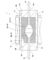
実施形態1の発電機能付きダンパ1は、図1に示すように、ケースであるシリンダ10、ピストン30、ロッド50、一対のロッドガイド(rod guide)70、複数の磁石粒子90、及びコイル部20を備えている。
実施形態1の発電機能付きダンパ1は、図1に示すように、ケースであるシリンダ10、ピストン30、ロッド50、一対のロッドガイド(rod guide)70、複数の磁石粒子90、及びコイル部20を備えている。
シリンダ10は両端が開口した筒状である。ピストン30は中央部30A及び両端部30Bを有している。中央部30Aは円柱形状である。両端部30Bは中央部30Aの両端面から離れる方向に外径が徐々に小さくなる円錐台形状である。ピストン30の外周面とシリンダ10の内周面との間には所定の隙間が形成されている。ピストン30はシリンダ10内に配置されている。
ロッド50は円柱状をなしている。ロッド50は、ピストン30の両端部30Bの先端に連続し、ピストン30の両方向に伸びている。ロッド50はシリンダ10の中心軸方向に伸びてシリンダ10の両端のそれぞれの開口端部10Aからシリンダ10の外部に突出している。つまり、ピストン30はロッド50に連結されている。ロッドガイド70は外周に鍔部70Bを有した円盤状をなしており、シリンダ10の両端部のそれぞれの開口端部10Aを閉鎖するようにそれぞれの開口端部10Aに連結されている。これらロッドガイド70は、円盤状の中心に円盤状の板厚方向に貫通して貫通孔70Aが設けられている。貫通孔70Aの内径はロッド50の外径より僅かに大きい。貫通孔70Aは、ロッドガイド70がシリンダ10の両端のそれぞれの開口端部10Aに固定された状態で、シリンダ10の中心軸方向に貫通している。これらロッドガイド70の貫通孔70Aにはロッド50が往復移動自在に挿通している。ロッド50及びピストン30は共にシリンダ10内をシリンダ10の中心軸方向に往復移動自在である。また、シリンダ10、ピストン30、ロッド50、及び一対のロッドガイド70は非磁性体である。
複数の磁石粒子90は、図2に示すように、球形状をなしている。これら磁石粒子90はデュロメータタイプ(durometer type)A硬度(以下、硬度という)が60のエラストマ(elastomer)であるシリコーンゴム(silicone rubber)製の弾性体である。また、これら磁石粒子90にはネオジム(neodymium)(Nd)粒子90Aが含有されている。これら磁石粒子90に含有されているネオジム(Nd)粒子90Aの量はおよそ60wt.%(17.78vol.%)である。ネオジム(Nd)粒子90Aは磁性を有している。つまり、磁石粒子90は磁性及び弾性を有している。こうして形成されたこれら磁石粒子90は着磁されて磁力を有している。すなわち、これら磁石粒子90は永久磁石の特性を有している。これら磁石粒子90は60%の充填率でシリンダ10と一対のロッドガイド70とで囲まれた空間(すなわち、シリンダ10内)に充填されている。
ここで、充填率は下記(1)式にて表される。なお、充填体積とは磁石粒子90を充填する空間の体積である。
ここで、充填率は下記(1)式にて表される。なお、充填体積とは磁石粒子90を充填する空間の体積である。

コイル部20は表面を絶縁膜で被覆した金属線を同軸に複数回巻いて、径方向に所定の幅を有し、シリンダ10の外径よりも僅かに大きい内径である円筒状に束ねたものである。また、コイル部20の金属線は両端のそれぞれが引き出されており、コイル部20で発生した誘導起電力に基づいて発生した電流を発電機能付きダンパ1の外部に設けられた電気機器等に供給する構成となっている(図示せず。)。コイル部20は、コイル部20の円筒状の内側がシリンダ10を挿入し、シリンダ10の外周面に沿うようにシリンダ10の外周面に配置されている。
こうして形成された発電機能付きダンパ1はシリンダ10の中心軸方向にピストン30が往復移動する際、磁石粒子90がピストン30の外周面とシリンダ10の内周面との間の所定の隙間を通過して移動する。このとき、シリンダ10の内周面とシリンダ10の内周面に当接する磁石粒子90との間、隣接する磁石粒子90同士の間、及びロッド50及びピストン30の外周面とロッド50及びピストン30の外周面に当接する磁石粒子90との間に摩擦力が発生する。また、ピストン30の移動する側に位置する磁石粒子90がピストン30によって押し潰される。このとき、ピストン30によって押し潰された磁石粒子90が発生する弾性反発力によってピストン30を押し返す。つまり、発電機能付きダンパ1はこうして生じる摩擦力や、弾性反発力に基づいて減衰力が発生する。
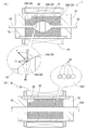
また、図11(A)に示すように、ピストン30の移動する側に位置する磁石粒子90がピストン30によって押し潰された際、磁石粒子90に対して、押圧力Fが加えられる。押圧力Fの向きは両端部30Bの傾斜面に対して垂直な向きである。押圧力Fはシリンダ10の中心軸方向の分力F1とシリンダ10の中心軸から離れる方向の分力F2とに分けることができる。ピストン30によって押し潰された磁石粒子90は分力F2によってシリンダ10の中心軸から離れる方向に移動する。
これに対して、図11(B)に示す発電機能付きダンパ61のように、ピストンを有していない場合、ロッド550がシリンダ10の中心軸方向に移動すると、ロッド550の外周面に当接する磁石粒子90がロッド550の外周面との間に発生する摩擦力によって転がったり、ロッド550と共に移動したりする。つまり、ピストンを有していない場合、磁石粒子90はシリンダ10の中心軸方向に移動するロッド550によって押し潰されない。このため、磁石粒子90に押圧力が加えられることがなく、ピストンが設けられた場合に比べて、磁石粒子90の流動は小さい。
つまり、ピストン30を設けることによってシリンダ10内に充填された磁石粒子90をより活発に流動させることができる。
また、図11(A)に示すように、ピストン30の移動する側に位置する磁石粒子90がピストン30によって押し潰された際、磁石粒子90に対して、押圧力Fが加えられる。押圧力Fの向きは両端部30Bの傾斜面に対して垂直な向きである。押圧力Fはシリンダ10の中心軸方向の分力F1とシリンダ10の中心軸から離れる方向の分力F2とに分けることができる。ピストン30によって押し潰された磁石粒子90は分力F2によってシリンダ10の中心軸から離れる方向に移動する。
これに対して、図11(B)に示す発電機能付きダンパ61のように、ピストンを有していない場合、ロッド550がシリンダ10の中心軸方向に移動すると、ロッド550の外周面に当接する磁石粒子90がロッド550の外周面との間に発生する摩擦力によって転がったり、ロッド550と共に移動したりする。つまり、ピストンを有していない場合、磁石粒子90はシリンダ10の中心軸方向に移動するロッド550によって押し潰されない。このため、磁石粒子90に押圧力が加えられることがなく、ピストンが設けられた場合に比べて、磁石粒子90の流動は小さい。
つまり、ピストン30を設けることによってシリンダ10内に充填された磁石粒子90をより活発に流動させることができる。
また、このとき、ロッド50及びピストン30の往復移動に伴って複数の磁石粒子90が形成する磁力線の向きが変化することによって複数の磁石粒子90が形成する磁力線がコイル部20内を貫通する数が変化するため、コイル部20に誘導起電力が発生する。つまり、発電機能付きダンパ1はコイル部20で発電する。
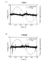
次に、発電機能付きダンパ1のロッド50及びピストン30を周波数1Hzにした場合における、コイル部20に発生する誘導起電力の大きさの時間に対する変化を示すグラフを図3(A)、(B)に示す。具体的には、(A)は1周期目の誘導起電力の大きさの時間に対する変化を示し、(B)は10周期目の誘導起電力の大きさの時間に対する変化を示す。
図3(A)、(B)に示すように、ロッド50及びピストン30がシリンダ10の中心軸方向に移動する全領域において、誘導起電力が発生している。また、1周期目と10周期目とで発生する誘導起電力の波形は互いに異なっている。これは、ロッド50及びピストン30がシリンダ10の中心軸方向に繰り返し往復移動する度に、複数の磁石粒子90が有する磁力線の向きが変化するため、コイル部20を貫通する磁力線の数の変化の仕方が異なるためであると考えられる。
次に、発電機能付きダンパ1のロッド50及びピストン30を周波数5Hzにした場合における、コイル部20に発生する誘導起電力の大きさの時間に対する変化を示すグラフを図4(A)、(B)に示す。具体的には、(A)は1周期目の誘導起電力の大きさの時間に対する変化を示し、(B)は10周期目の誘導起電力の大きさの時間に対する変化を示す。
図4(A)、(B)に示すように、ロッド50及びピストン30がシリンダ10の中心軸方向に移動する全領域において誘導起電力が発生している。また、ロッド50及びピストン30が周波数1Hzの場合に比べて誘導起電力の大きさが大きい。これは、周波数1Hzの場合に比べてシリンダ10内に充填された磁石粒子90がより活発に流動して、コイル部20内を貫通する磁力線の数がより活発に変化するためであると考えられる。また、1周期目と10周期目とで発生する誘導起電力の波形は互いに異なっている。これは、ロッド50及びピストン30がシリンダ10の中心軸方向に繰り返し往復移動する度に、複数の磁石粒子90が有する磁力線の向きが変化するため、コイル部20を貫通する磁力線の数の変化の仕方が異なるためであると考えられる。
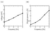
次に、発電機能付きダンパ1のロッド50及びピストン30を周波数1~5Hzの間で1Hz毎に変化させた場合のそれぞれにおけるコイル部20で発生する誘導起電力、及び誘導起電力に基づいて発生した電力の大きさを図5(A)、(B)に示す。具体的には、図5(A)はロッド50及びピストン30を所定の回数往復移動させた間にコイル部20で発生する誘導起電力の平均値の大きさを示し、図5(B)はコイル部20で発生した誘導起電力に基づいて発生した電力の大きさを示す。具体的には、図5(A)におけるそれぞれの周波数における誘導起電力の平均値を2乗した値をコイル部20が有する抵抗値(およそ6.5Ω(オーム(ohm)))で除した値である。
図5(A)、(B)に示すように、ロッド50及びピストン30の周波数が大きくなるにつれて、コイル部20で発生する誘導起電力、及びコイル部20で発生した誘導起電力に基づいて発生した電力の大きさが大きくなっている。これは、ロッド50及びピストン30の周波数が大きくなるにつれて、シリンダ10内に充填された磁石粒子90がより活発に流動して、コイル部20内を貫通する磁力線の数がより活発に変化するためであると考えられる。
このように、発電機能付きダンパ1は、ロッド50及びピストン30がシリンダ10の中心軸方向に往復移動する際、シリンダ10内に充填された磁石粒子90がシリンダ10内を移動することによって減衰力を発生する。
また、シリンダ10内を移動する複数の磁石粒子90が形成する磁力線の向きが変化すると、コイル部20内を貫通する磁力線の数が変化する。これによりコイル部20には誘導起電力が発生する。つまり、発電機能付きダンパ1は発電する。
また、シリンダ10内を移動する複数の磁石粒子90が形成する磁力線の向きが変化すると、コイル部20内を貫通する磁力線の数が変化する。これによりコイル部20には誘導起電力が発生する。つまり、発電機能付きダンパ1は発電する。
したがって、本発明の発電機能付きダンパ1は良好に減衰力を発生し、且つ良好に発電することができる。
また、発電機能付きダンパ1の磁石粒子90は弾性を有している。このため、ロッド50が軸方向に往復移動又は軸周りに回転する際、シリンダ10内に充填された複数の磁石粒子90が弾性変形する。この際に生じる磁石粒子90同士の摩擦力や、磁石粒子90の弾性反発力によって、発電機能付きダンパ1は減衰力を発生する。また、磁石粒子90が弾性を有しているため、隣り合う磁石粒子90同士が互いに弾性変形することによって、磁石粒子90同士が焼きつき難い。このため、発電機能付きダンパ1はロッド50の軸方向の往復移動又は軸周りの回転を妨げ難い。
また、発電機能付きダンパ1はシリンダ10内に配置され、ロッド50に連結されてロッド50と共に往復移動するピストン30を備えている。このため、発電機能付きダンパ1はピストン30によってシリンダ10内に充填された磁石粒子90をより活発に流動させることができる。このため、発電機能付きダンパ1は磁石粒子90が有する磁力線がコイル部20内をより活発に通過する。これにより、発電機能付きダンパ1はコイル部20内を貫通する磁力線の数がより活発に変化し易くなり、コイル部20により大きな誘導起電力が発生し易くなる。
<実施形態2>
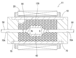
実施形態2の発電機能付きダンパ11は、図6に示すように、ピストン130に永久磁石である磁石40が設けられている点が実施形態1と相違する。他の構成は実施形態1と同一であり、同一の構成は同一の符号を付し、詳細な説明を省略する。
実施形態2の発電機能付きダンパ11は、図6に示すように、ピストン130に永久磁石である磁石40が設けられている点が実施形態1と相違する。他の構成は実施形態1と同一であり、同一の構成は同一の符号を付し、詳細な説明を省略する。
実施形態2の発電機能付きダンパ11は、図6に示すように、ピストン130内に磁石40が設けられている。磁石40は永久磁石の特性を有しており、例えば、円柱状をなして形成されており、中心軸がロッド50及びピストン130の中心軸に同軸にピストン130内に配置されている。また、磁石40は、例えば、円柱状の一端側がN極、他端側がS極になるように着磁されている。
こうして形成された発電機能付きダンパ11はシリンダ10の中心軸方向にピストン130が往復移動する際、磁石粒子90がピストン130の外周面とシリンダ10の内周面との間の所定の隙間を通過して移動する。このとき、シリンダ10の内周面とシリンダ10の内周面に当接する磁石粒子90との間、隣接する磁石粒子90同士の間、及びロッド50及びピストン130の外周面とロッド50及びピストン130の外周面に当接する磁石粒子90との間に摩擦力が発生する。また、ピストン130の移動する側に位置する磁石粒子90がピストン130によって押し潰される。このとき、ピストン130によって押し潰された磁石粒子90が発生する弾性反発力によってピストン130を押し返す。つまり、発電機能付きダンパ11はこうして生じる摩擦力や、弾性反発力に基づいて減衰力が発生する。
また、このとき、ロッド50及びピストン130の往復移動に伴って複数の磁石粒子90が形成する磁力線の向きが変化することによって複数の磁石粒子90が形成する磁力線がコイル部20内を貫通する数が変化するため、コイル部20に誘導起電力が発生する。つまり、発電機能付きダンパ11はコイル部20で発電する。
このように、発電機能付きダンパ11は、ロッド50及びピストン130がシリンダ10の中心軸方向に往復移動する際、シリンダ10内に充填された磁石粒子90がシリンダ10内を移動することによって減衰力を発生する。
また、シリンダ10内を移動する複数の磁石粒子90が形成する磁力線の向きが変化すると、コイル部20内を貫通する磁力線の数が変化する。これによりコイル部20には誘導起電力が発生する。つまり、この発電機能付きダンパ11は発電する。
また、シリンダ10内を移動する複数の磁石粒子90が形成する磁力線の向きが変化すると、コイル部20内を貫通する磁力線の数が変化する。これによりコイル部20には誘導起電力が発生する。つまり、この発電機能付きダンパ11は発電する。
したがって、本発明の発電機能付きダンパ11も良好に減衰力を発生し、且つ良好に発電することができる。
また、この発電機能付きダンパ11はピストン130内に磁石40が配置され、コイル部20はシリンダ10に配置されている。このため、発電機能付きダンパ11はピストン130内の磁石40によってシリンダ10内に充填された磁石粒子90が有する磁力線の向きが揃うように磁石粒子90の向きを揃えつつ、ピストン130によってシリンダ10内に充填された磁石粒子90をより活発に流動させることができる。これにより、この発電機能付きダンパ11は向きが揃った磁力線がコイル部20内を貫通する数がより活発に変化し易くなり、シリンダ10に配置されたコイル部20により大きな誘導起電力が発生し易くなる。
<実施形態3>
実施形態3の発電機能付きダンパ21は、図7に示すように、ピストン230内にコイル部120が設けられている点が実施形態1、2と相違する。他の構成は実施形態1、2と同一であり、同一の構成は同一の符号を付し、詳細な説明を省略する。
実施形態3の発電機能付きダンパ21は、図7に示すように、ピストン230内にコイル部120が設けられている点が実施形態1、2と相違する。他の構成は実施形態1、2と同一であり、同一の構成は同一の符号を付し、詳細な説明を省略する。
実施形態3の発電機能付きダンパ21は、ピストン230内にコイル部120が設けられている。具体的には、図7に示すように、円筒状をなしたコイル部120の中心軸が、ロッド150及びピストン230の中心軸に同軸になるようにコイル部120がピストン230内に配置されている。また、コイル部120から引き出された金属線の両端は、ロッド150の片方側の内側を経由して、発電機能付きダンパ21の外部に引き出されており、コイル部120で発生した誘導起電力に基づいて発生した電流を発電機能付きダンパ21の外部に設けられた電気機器等に供給する構成となっている(図示せず。)。
こうして形成された発電機能付きダンパ21はシリンダ10の中心軸方向にピストン230が往復移動する際、磁石粒子90がピストン230の外周面とシリンダ10の内周面との間の所定の隙間を通過して移動する。このとき、シリンダ10の内周面とシリンダ10の内周面に当接する磁石粒子90との間、隣接する磁石粒子90の間、及びロッド150及びピストン230の外周面とロッド150及びピストン230の外周面に当接する磁石粒子90との間に摩擦力が発生する。また、ピストン230の移動する側に位置する磁石粒子90がピストン230によって押し潰される。このとき、ピストン230によって押し潰された磁石粒子90が発生する弾性反発力によってピストン230を押し返す。つまり、発電機能付きダンパ21はこうして発生する摩擦力や、弾性反発力に基づいて減衰力が発生する。
また、このとき、ロッド150及びピストン230の往復移動に伴って複数の磁石粒子90が形成する磁力線の向きが変化することによって複数の磁石粒子90が形成する磁力線がコイル部120内を貫通する数が変化するため、コイル部120に誘導起電力が発生する。つまり、発電機能付きダンパ21はコイル部120で発電する。
このように、発電機能付きダンパ21は、ロッド150及びピストン230がシリンダ10の中心軸方向に往復移動する際、シリンダ10内に充填された磁石粒子90がシリンダ10内を移動することによって減衰力を発生する。
また、シリンダ10内を移動する複数の磁石粒子90が形成する磁力線の向きが変化すると、コイル部120内を貫通する磁力線の数が変化する。これによりコイル部120には誘導起電力が発生する。つまり、発電機能付きダンパ21は発電する。
また、シリンダ10内を移動する複数の磁石粒子90が形成する磁力線の向きが変化すると、コイル部120内を貫通する磁力線の数が変化する。これによりコイル部120には誘導起電力が発生する。つまり、発電機能付きダンパ21は発電する。
したがって、本発明の発電機能付きダンパ21も良好に減衰力を発生し、且つ良好に発電することができる。
また、発電機能付きダンパ21はピストン230内にコイル部120が配置されている。このため、ピストン230内に配置されたコイル部120が、シリンダ10内の磁石粒子90に対する位置が確実に変化することができる。このため、発電機能付きダンパ21は磁石粒子90が有する磁力線がコイル部120内を確実に通過する。これにより、発電機能付きダンパ21はコイル部120内を貫通する磁力線の数が変化し易く、コイル部120により大きな誘導起電力が発生し易くなる。さらに、発電機能付きダンパ21はピストン230によってシリンダ10内に充填された磁石粒子90を活発に流動させることができるため、コイル部120により大きな誘導起電力が発生し易くなる。
<実施形態4>
実施形態4の発電機能付きダンパ31は、図8に示すように、ピストンを備えていない点、及びロッド250内に永久磁石である磁石140が設けられている点が実施形態1~3と相違する。他の構成は実施形態1~3と同一であり、同一の構成は同一の符号を付し、詳細な説明を省略する。
実施形態4の発電機能付きダンパ31は、図8に示すように、ピストンを備えていない点、及びロッド250内に永久磁石である磁石140が設けられている点が実施形態1~3と相違する。他の構成は実施形態1~3と同一であり、同一の構成は同一の符号を付し、詳細な説明を省略する。
実施形態4の発電機能付きダンパ31は、図8に示すように、ロッド250内に磁石140が設けられている。磁石140は永久磁石の特性を有しており、例えば、円柱状をなして形成されており、中心軸がロッド250の中心軸に同軸にロッド250内に配置されている。また、磁石140は、例えば、円柱状の一端側がN極、他端側がS極になるように着磁されている。
こうして形成された発電機能付きダンパ31はシリンダ10の中心軸方向にロッド250が往復移動する際、磁石粒子90がロッド250の外周面とシリンダ10の内周面との間の所定の隙間を移動する。具体的には、ロッド250の外周面に当接する磁石粒子90がロッド250の外周面との間に発生する摩擦力によってロッド250と共に移動する。このとき、シリンダ10の内周面とシリンダ10の内周面に当接する磁石粒子90との間、及び隣接する磁石粒子90同士の間にも摩擦力が発生する。つまり、発電機能付きダンパ31はこうして生じる摩擦力に基づいて減衰力が発生する。
また、このとき、ロッド250の往復移動に伴って複数の磁石粒子90が形成する磁力線の向きが変化することによって複数の磁石粒子90が形成する磁力線がコイル部20内を貫通する数が変化するため、コイル部20に誘導起電力が発生する。つまり、発電機能付きダンパ31はコイル部20で発電する。
このように、発電機能付きダンパ31は、ロッド250がシリンダ10の中心軸方向に往復移動する際、シリンダ10内に充填された磁石粒子90がシリンダ10内を移動することによって減衰力を発生する。
また、シリンダ10内を移動する複数の磁石粒子90が形成する磁力線の向きが変化すると、コイル部20内を貫通する磁力線の数が変化する。これによりコイル部20には誘導起電力が発生する。つまり、発電機能付きダンパ31は発電する。
また、シリンダ10内を移動する複数の磁石粒子90が形成する磁力線の向きが変化すると、コイル部20内を貫通する磁力線の数が変化する。これによりコイル部20には誘導起電力が発生する。つまり、発電機能付きダンパ31は発電する。
したがって、本発明の発電機能付きダンパ31も良好に減衰力を発生し、且つ良好に発電することができる。
また、発電機能付きダンパ31はロッド250内に磁石140が配置され、コイル部20はシリンダ10に配置されている。このため、発電機能付きダンパ31はロッド250内の磁石140によって磁石粒子90が有する磁力線の向きが揃うように磁石粒子90の向きを揃えることができる。これにより、この発電機能付きダンパ31は向きが揃った磁力線がコイル部20内を貫通する数が変化するため、シリンダ10に配置されたコイル部20により大きな誘導起電力が発生し易くなる。
<実施形態5>
実施形態5の発電機能付きダンパ41は、図9に示すように、ピストンを備えていない点、及びロッド350内にコイル部220が設けられている点が実施形態1~4と相違する。他の構成は実施形態1~4と同一であり、同一の構成は同一の符号を付し、詳細な説明を省略する。
実施形態5の発電機能付きダンパ41は、図9に示すように、ピストンを備えていない点、及びロッド350内にコイル部220が設けられている点が実施形態1~4と相違する。他の構成は実施形態1~4と同一であり、同一の構成は同一の符号を付し、詳細な説明を省略する。
実施形態5の発電機能付きダンパ41はロッド350内にコイル部220が設けられている。具体的には、図9に示すように、円筒状をなしたコイル部220の中心軸が、ロッド350の中心軸に同軸になるようにコイル部220がロッド350内に配置されている。また、コイル部220から引き出された金属線の両端は、ロッド350の片方側の内側を経由して、発電機能付きダンパ41の外部に引き出されており、コイル部220で発生した誘導起電力に基づいて発生した電流を発電機能付きダンパ41の外部に設けられた電気機器等に供給する構成となっている(図示せず。)。
こうして形成された発電機能付きダンパ41はシリンダ10の中心軸方向にロッド350が往復移動する際、磁石粒子90がロッド350の外周面とシリンダ10の内周面との間の所定の隙間を移動する。具体的には、ロッド350の外周面に当接する磁石粒子90がロッド350の外周面との間に発生する摩擦力によってロッド350と共に移動する。このとき、シリンダ10の内周面とシリンダ10の内周面に当接する磁石粒子90との間、及び隣接する磁石粒子90同士の間にも摩擦力が発生する。つまり、発電機能付きダンパ41はこうして生じる摩擦力に基づいて減衰力が発生する。
また、このとき、ロッド350の往復移動に伴って複数の磁石粒子90が形成する磁力線の向きが変化することによって複数の磁石粒子90が形成する磁力線がコイル部220内を貫通する数が変化するため、コイル部220に誘導起電力が発生する。つまり、発電機能付きダンパ41はコイル部220で発電する。
このように、発電機能付きダンパ41は、ロッド350がシリンダ10の中心軸方向に往復移動する際、シリンダ10内に充填された磁石粒子90がシリンダ10内を移動することによって減衰力を発生する。
また、シリンダ10内を移動する複数の磁石粒子90が形成する磁力線の向きが変化すると、コイル部220内を貫通する磁力線の数が変化する。これによりコイル部220には誘導起電力が発生する。つまり、発電機能付きダンパ41は発電する。
また、シリンダ10内を移動する複数の磁石粒子90が形成する磁力線の向きが変化すると、コイル部220内を貫通する磁力線の数が変化する。これによりコイル部220には誘導起電力が発生する。つまり、発電機能付きダンパ41は発電する。
したがって、本発明の発電機能付きダンパ41も良好に減衰力を発生し、且つ良好に発電することができる。
また、この発電機能付きダンパ41はロッド350内にコイル部220が配置されている。このため、ロッド350内に配置されたコイル部220が、シリンダ10内の磁石粒子90に対する位置が確実に変化することができる。このため、発電機能付きダンパ41は磁石粒子90が有する磁力線がコイル部220内を確実に通過する。これにより、発電機能付きダンパ41はコイル部220内を貫通する磁力線の数が変化し易く、コイル部220により大きな誘導起電力が発生し易くなる。
<実施形態6>
実施形態6の発電機能付きダンパ51は、図10(A)、(B)に示すように、シリンダ110の形状、ロッドガイド170の形状、ロッド450及び回転子35が軸周りであるシリンダ110の中心軸周りに回転する点、コイル部320の形状、及びコイル部320のシリンダ110に対する配置等が実施形態1~5と相違する。他の構成は実施形態1~5と同一であり、同一の構成は同一の符号を付し、詳細な説明を省略する。
実施形態6の発電機能付きダンパ51は、図10(A)、(B)に示すように、シリンダ110の形状、ロッドガイド170の形状、ロッド450及び回転子35が軸周りであるシリンダ110の中心軸周りに回転する点、コイル部320の形状、及びコイル部320のシリンダ110に対する配置等が実施形態1~5と相違する。他の構成は実施形態1~5と同一であり、同一の構成は同一の符号を付し、詳細な説明を省略する。
シリンダ110は、図10(A)、(B)に示すように、両端が開口した筒状である。
ロッドガイド170である第1ロッドガイド171は円盤状であり、シリンダ110の一方の端面に他方の面を当接させてシリンダ110の一方側を閉鎖するようにシリンダ110に連結されている。第1ロッドガイド171の円盤状の中心には板厚方向に貫通して第1貫通孔171Aが設けられている。また、第1ロッドガイド171の他方の面側の第1貫通孔171Aには第1貫通孔171Aの内周面から内方向に平板状に伸びる第1付当て部171Bが形成されている。第1付当て部171Bの内径は後述するロッド450の外径より僅かに大きい。第1貫通孔171Aにはシールドベアリング(shield bearing)60が嵌め込まれており、シールドベアリング60の片方の面が第1付当て部171Bの一方の面に当接している。
ロッドガイド170である第2ロッドガイド172は円盤状であり、シリンダ110の他方の端面に一方の面を当接させてシリンダ110の他方側を閉鎖するようにシリンダ110に連結されている。第2ロッドガイド172の円盤状の中心には板厚方向に貫通して第2貫通孔172Aが設けられている。また、板厚方向に貫通する第2貫通孔172Aの中間部には第2貫通孔172Aの内周面から内方向に平板状に伸びる第2付当て部172Bが形成されている。第2付当て部172Bの内径はロッド450の外径より僅かに大きい。また、第2貫通孔172Aの内径は、第2付当て部172Bの一方の面から第2ロッドガイド172の一方の面までの間(以降、第2貫通孔172Aの一方側という)に比べて、第2付当て部172Bの他方の面から第2ロッドガイド172の他方の面までの間(以降、第2貫通孔172Aの他方側という)の方が小さい。第2貫通孔172Aの他方側にはシールドベアリング60が嵌め込まれており、シールドベアリング60の片方の面が第2付当て部172Bの他方の面に当接している。
ロッドガイド170である第3ロッドガイド173は第1ロッドガイド171、及び第2ロッドガイド172より厚い円盤状である。また、第3ロッドガイド173は円盤状の外径がシリンダ110の内径とほぼ同じである。第3ロッドガイド173は円盤状の一方の面を第1ロッドガイド171の他方の面に当接させて、シリンダ110の一方の開口端部110Aに嵌め込まれて第1ロッドガイド171に連結されている。第3ロッドガイド173の円盤状の中心には板厚方向に貫通して第3貫通孔173Aが設けられている。また、第3ロッドガイド173の他方の面側の第3貫通孔173Aには第3貫通孔173Aの内周面から内方向に平板状に伸びる第3付当て部173Bが形成されている。第3付当て部173Bの内径は後述する回転子35の第1端部35Bの外径より僅かに大きい。
ロッドガイド170である第4ロッドガイド174は第1ロッドガイド171、及び第2ロッドガイド172より厚く、第3ロッドガイド173より薄い円盤状である。また、第4ロッドガイド174は円盤状の外径がシリンダ110の内径とほぼ同じである。第4ロッドガイド174は円盤状の他方の面を第2ロッドガイド172の一方の面に当接させて、シリンダ110の他方の開口端部110Aに嵌め込まれて第2ロッドガイド172に連結されている。第4ロッドガイド174の円盤状の中心には板厚方向に貫通して第4貫通孔174Aが設けられている。また、第4ロッドガイド174の一方の面側の第4貫通孔174Aには第4貫通孔174Aの内周面から内方向に平板状に伸びる第4付当て部174Bが形成されている。第4付当て部174Bの内径は回転子35の第2端部35Cの外径より僅かに大きい。
回転子35は中央部35A、第1端部35B、及び第2端部35Cを有している。中央部35Aは第3ロッドガイド173の他方の面と第4ロッドガイド174の一方の面との間に配置されており、シリンダ110の中心軸に直交する断面形状が正方形状をなしている(図10(B)参照。)。また、正方形状を形成する四つの面の内の隣り合う二面の間には稜(以降、稜という)が形成されている。
また、中央部35Aのシリンダ110の中心軸方向の両端のそれぞれにはシリンダ110の中心軸に直交する第1平面35Dが形成されている。
第1端部35B及び第2端部35Cはそれぞれが円柱状をなして、中央部35Aの2つの第1平面35Dのそれぞれの中央から互いに反対向きに伸びている。また、これら第1端部35B及び第2端部35Cの中央部35Aから離れた側にはシリンダ110の中心軸に直交する第2平面35Eが形成されている。
ロッド450は第1端部35B及び第2端部35Cの第2平面35Eの中央のそれぞれから伸びている。つまり、回転子35はロッド450に連結されている。ロッド450と第1端部35B及び第2端部35Cとは互いに同軸である。回転子35はシリンダ110内に配置されている。
ロッド450は第1ロッドガイド171、及び第2ロッドガイド172のそれぞれに嵌め込まれたシールドベアリング60を介して第1ロッドガイド171、及び第2ロッドガイド172に回転自在に連結されている。また、第1端部35B及び第2端部35Cのそれぞれは第3ロッドガイド173の第3貫通孔173Aの第3付当て部173B、及び第4ロッドガイド174の第4貫通孔174Aの第4付当て部174Bに回転自在に挿通されている。
また、第3ロッドガイド173の第3貫通孔173Aの内側にはスラストベアリング(thrust bearing)80が配置されており、第3付当て部173Bに挿通された第1端部35Bの第2平面35Eと第1ロッドガイド171の他方の面とでスラストベアリング80が挟まれている。また、第4ロッドガイド174の第4貫通孔174Aの内側にもスラストベアリング80が配置されており、第4付当て部174Bに挿通された第2端部35Cの第2平面35Eと第2ロッドガイド172の一方の面とでスラストベアリング80が挟まれている。これにより、ロッド450及び回転子35は共にシリンダ110の中心軸回りに回転自在である。
コイル部320は表面を絶縁膜で被覆した金属線を同軸に複数回巻いて、径方向に所定の幅を有し、円環状に束ねたものである。発電機能付きダンパ51はシリンダ110の外周面に4つのコイル部320がそれぞれの円環状の一端側をシリンダ110の外周面に沿うように配置されている。
こうして形成された発電機能付きダンパ51はシリンダ110の中心軸周りにロッド450及び回転子35が回転する際、シリンダ110内に充填された磁石粒子90が流動する。このとき、シリンダ110の内周面とシリンダ110の内周面に当接する磁石粒子90との間、隣接する磁石粒子90同士の間、及び回転子35の中央部35Aの表面と回転子35の中央部35Aの表面に当接する磁石粒子90との間に摩擦力が発生する。また、磁石粒子90は回転する回転子35の中央部35Aによって押し潰される。このとき、回転子35の中央部35Aによって押し潰された磁石粒子90が発生する弾性反発力によって回転子35の中央部35Aを押し返す。つまり、発電機能付きダンパ51はこうして生じる摩擦力や、弾性反発力に基づいて回転子35が回転する方向と反対の方向に減衰力が発生する。
また、このとき、ロッド450及び回転子35の回転に伴って複数の磁石粒子90が形成する磁力線の向きが変化することによって複数の磁石粒子90が形成する磁力線が4つのコイル部320内を貫通する数が変化するため、これらコイル部320に誘導起電力が発生する。つまり、発電機能付きダンパ51は4つのコイル部320で発電する。
このように、発電機能付きダンパ51は、ロッド450及び回転子35がシリンダ110の中心軸周りに回転する際、シリンダ110内に充填された磁石粒子90がシリンダ110内を移動することによって減衰力を発生する。
また、シリンダ110内を移動する複数の磁石粒子90が形成する磁力線の向きが変化すると、4つのコイル部320内を貫通する磁力線の数が変化する。これによりコイル部320には誘導起電力が発生する。つまり、発電機能付きダンパ51は発電する。
また、シリンダ110内を移動する複数の磁石粒子90が形成する磁力線の向きが変化すると、4つのコイル部320内を貫通する磁力線の数が変化する。これによりコイル部320には誘導起電力が発生する。つまり、発電機能付きダンパ51は発電する。
したがって、本発明の発電機能付きダンパ51も良好に減衰力を発生し、且つ良好に発電することができる。
また、発電機能付きダンパ51はシリンダ110に配置され、シリンダ110の中心軸周りに回転自在なロッド450に連結され、ロッド450と共にシリンダ110内で回転する回転子35を備えている。このため、ロッド450と回転子35とがシリンダ110の中心軸周りに回転する際、シリンダ110内に充填された磁石粒子90がロッド450と回転子35とが回転する方向に流動する。これにより、発電機能付きダンパ51はロッド450と回転子35とが回転する方向と反対の方向に減衰力を発生しつつ、コイル部320に誘導起電力を発生することができる。
本発明は上記記述及び図面によって説明した実施形態1~6に限定されるものではなく、例えば次のような実施形態も本発明の技術的範囲に含まれる。
(1)実施形態1、3、5では、コイル部をシリンダの外周面や、ピストン内やロッド内にそれぞれ設けているが、コイル部をシリンダの外周面、ロッド、及びピストンに併設してもよい。
(2)実施形態1~6では、磁石粒子が硬度60のエラストマであるシリコーンゴム製の弾性体であったが、磁性を有するものであれば他の材料であってもよく、また、これら材料を複合的に用いてもよい。また、磁石粒子の硬度がおよそ40~90でもよい。また、弾性変形しない材料であってもよい。
(3)実施形態1~6では、シリンダ内に充填する複数の磁石粒子の互いの大きさは一様であったが、複数種類の粒子径の磁石粒子をシリンダ内に充填してもよい。
(1)実施形態1、3、5では、コイル部をシリンダの外周面や、ピストン内やロッド内にそれぞれ設けているが、コイル部をシリンダの外周面、ロッド、及びピストンに併設してもよい。
(2)実施形態1~6では、磁石粒子が硬度60のエラストマであるシリコーンゴム製の弾性体であったが、磁性を有するものであれば他の材料であってもよく、また、これら材料を複合的に用いてもよい。また、磁石粒子の硬度がおよそ40~90でもよい。また、弾性変形しない材料であってもよい。
(3)実施形態1~6では、シリンダ内に充填する複数の磁石粒子の互いの大きさは一様であったが、複数種類の粒子径の磁石粒子をシリンダ内に充填してもよい。
(4)実施形態1~6では、磁石粒子にネオジム(Nd)の粒子が含有されているが、磁性を有する材料であれば他の材料を含有してもよい。また、これら材料を複合的に含有してもよい。
(5)実施形態1~6では、シリンダの開口端部のそれぞれからシリンダの外部にロッドが突出しているが、ピストン(回転子)の一方からロッドが突出して、ロッドがシリンダの一方の開口端部からシリンダの外部に突出していてもよい。
(6)実施形態1~5では、円筒形状のコイル部が1つ設けられているが、コイル部を複数設けてもよい。
(7)実施形態6では、正方形状を形成する四つの面の内の隣り合う二面の間には稜が形成されているが、これら稜は厳密な角に限らず、面取りを施したり、二つの面を連続するように曲面で形成したりしてもよい。
(5)実施形態1~6では、シリンダの開口端部のそれぞれからシリンダの外部にロッドが突出しているが、ピストン(回転子)の一方からロッドが突出して、ロッドがシリンダの一方の開口端部からシリンダの外部に突出していてもよい。
(6)実施形態1~5では、円筒形状のコイル部が1つ設けられているが、コイル部を複数設けてもよい。
(7)実施形態6では、正方形状を形成する四つの面の内の隣り合う二面の間には稜が形成されているが、これら稜は厳密な角に限らず、面取りを施したり、二つの面を連続するように曲面で形成したりしてもよい。
10,110…シリンダ(ケース)、20,120,220,320…コイル部、30,130,230…ピストン、35…回転子、40,140…磁石(永久磁石)、50,150,250,350,450,550…ロッド、90…磁石粒子
Claims (20)
- ケースと、
前記ケースから外部に突出し、軸方向に往復移動自在又は軸周りに回転自在なロッドと、
前記ケース内に充填され、永久磁石の特性を有した複数の磁石粒子と、
前記ロッドの往復移動、又は軸周りの回転に伴って複数の前記磁石粒子が形成する磁力線の向きが変化することによって前記コイル部内を貫通する前記磁力線の数が変化して誘導起電力が発生するコイル部と、
を備えていることを特徴とする発電機能付きダンパ。 - 前記磁石粒子は弾性を有していることを特徴とする請求項1に記載の発電機能付きダンパ。
- 前記ロッド内に前記コイル部が配置されていることを特徴とする請求項1に記載の発電機能付きダンパ。
- 前記ロッド内に永久磁石が配置され、前記コイル部は前記ケースに配置されていることを特徴とする請求項1に記載の発電機能付きダンパ。
- 前記ケース内に配置され、前記ロッドに連結されて前記ロッドと共に往復移動するピストンを備えていることを特徴とする請求項1に記載の発電機能付きダンパ。
- 前記ロッド内に前記コイル部が配置されていることを特徴とする請求項2に記載の発電機能付きダンパ。
- 前記ロッド内に永久磁石が配置され、前記コイル部は前記ケースに配置されていることを特徴とする請求項2に記載の発電機能付きダンパ。
- 前記ケース内に配置され、軸周りに回転自在な前記ロッドに連結され、前記ロッドと共にケース内を回転する回転子を備えていることを特徴とする請求項1に記載の発電機能付きダンパ。
- 前記ケース内に配置され、前記ロッドに連結されて前記ロッドと共に往復移動するピストンを備えていることを特徴とする請求項2に記載の発電機能付きダンパ。
- 前記ケース内に配置され、前記ロッドに連結されて前記ロッドと共に往復移動するピストンを備えていることを特徴とする請求項6に記載の発電機能付きダンパ。
- 前記ケース内に配置され、前記ロッドに連結されて前記ロッドと共に往復移動するピストンを備えていることを特徴とする請求項7に記載の発電機能付きダンパ。
- 前記ピストン内に永久磁石が配置され、前記コイル部は前記ケースに配置されていることを特徴とする請求項9に記載の発電機能付きダンパ。
- 前記ピストン内に永久磁石が配置され、前記コイル部は前記ケースに配置されていることを特徴とする請求項10に記載の発電機能付きダンパ。
- 前記ピストン内に永久磁石が配置され、前記コイル部は前記ケースに配置されていることを特徴とする請求項11に記載の発電機能付きダンパ。
- 前記ピストン内に前記コイル部が配置されていることを特徴とする請求項9に記載の発電機能付きダンパ。
- 前記ピストン内に前記コイル部が配置されていることを特徴とする請求項10に記載の発電機能付きダンパ。
- 前記ピストン内に前記コイル部が配置されていることを特徴とする請求項11に記載の発電機能付きダンパ。
- 前記ケース内に配置され、軸周りに回転自在な前記ロッドに連結され、前記ロッドと共にケース内を回転する回転子を備えていることを特徴とする請求項2に記載の発電機能付きダンパ。
- 前記ケース内に配置され、軸周りに回転自在な前記ロッドに連結され、前記ロッドと共にケース内を回転する回転子を備えていることを特徴とする請求項6に記載の発電機能付きダンパ。
- 前記ケース内に配置され、軸周りに回転自在な前記ロッドに連結され、前記ロッドと共にケース内を回転する回転子を備えていることを特徴とする請求項7に記載の発電機能付きダンパ。
Priority Applications (1)
| Application Number | Priority Date | Filing Date | Title |
|---|---|---|---|
| KR1020177035297A KR20190140490A (ko) | 2017-04-19 | 2017-07-14 | 발전 기능 부착 댐퍼 |
Applications Claiming Priority (2)
| Application Number | Priority Date | Filing Date | Title |
|---|---|---|---|
| JP2017-082521 | 2017-04-19 | ||
| JP2017082521A JP6343060B1 (ja) | 2017-04-19 | 2017-04-19 | 発電機能付きダンパ |
Publications (1)
| Publication Number | Publication Date |
|---|---|
| WO2018193641A1 true WO2018193641A1 (ja) | 2018-10-25 |
Family
ID=62555262
Family Applications (1)
| Application Number | Title | Priority Date | Filing Date |
|---|---|---|---|
| PCT/JP2017/025674 Ceased WO2018193641A1 (ja) | 2017-04-19 | 2017-07-14 | 発電機能付きダンパ |
Country Status (4)
| Country | Link |
|---|---|
| JP (1) | JP6343060B1 (ja) |
| KR (1) | KR20190140490A (ja) |
| TW (1) | TW201839289A (ja) |
| WO (1) | WO2018193641A1 (ja) |
Families Citing this family (5)
| Publication number | Priority date | Publication date | Assignee | Title |
|---|---|---|---|---|
| JP2020026822A (ja) * | 2018-08-10 | 2020-02-20 | Kyb株式会社 | 粒状体ダンパ |
| CN111469532B (zh) * | 2020-05-29 | 2023-12-08 | 湖北科技学院 | 一种悬浮式印刷辊在线扭矩监测方法 |
| CN115143218B (zh) * | 2022-06-30 | 2024-06-04 | 重庆大学 | 磁流变调谐颗粒质量阻尼器 |
| WO2024089901A1 (ja) * | 2022-10-28 | 2024-05-02 | 株式会社イノアックコーポレーション | 電気機器 |
| CN119633484B (zh) * | 2025-02-14 | 2025-09-05 | 杭州泰恩智达装备科技有限公司 | 一种过滤系统 |
Citations (5)
| Publication number | Priority date | Publication date | Assignee | Title |
|---|---|---|---|---|
| JP2003223220A (ja) * | 2002-01-31 | 2003-08-08 | Tokico Ltd | 電磁サスペンション装置 |
| JP4418998B2 (ja) * | 2000-04-28 | 2010-02-24 | 日立オートモティブシステムズ株式会社 | 電磁サスペンション制御装置 |
| JP2013032714A (ja) * | 2011-08-01 | 2013-02-14 | Daikin Industries Ltd | 空気圧縮機及び太陽光追尾システム |
| JP2013159204A (ja) * | 2012-02-03 | 2013-08-19 | Kyb Co Ltd | サスペンション装置 |
| JP2015028365A (ja) * | 2013-07-30 | 2015-02-12 | 国立大学法人 名古屋工業大学 | 傾斜して設置可能な粒状体を用いたダンパ装置 |
-
2017
- 2017-04-19 JP JP2017082521A patent/JP6343060B1/ja active Active
- 2017-07-14 KR KR1020177035297A patent/KR20190140490A/ko not_active Withdrawn
- 2017-07-14 WO PCT/JP2017/025674 patent/WO2018193641A1/ja not_active Ceased
- 2017-08-11 TW TW106127317A patent/TW201839289A/zh unknown
Patent Citations (5)
| Publication number | Priority date | Publication date | Assignee | Title |
|---|---|---|---|---|
| JP4418998B2 (ja) * | 2000-04-28 | 2010-02-24 | 日立オートモティブシステムズ株式会社 | 電磁サスペンション制御装置 |
| JP2003223220A (ja) * | 2002-01-31 | 2003-08-08 | Tokico Ltd | 電磁サスペンション装置 |
| JP2013032714A (ja) * | 2011-08-01 | 2013-02-14 | Daikin Industries Ltd | 空気圧縮機及び太陽光追尾システム |
| JP2013159204A (ja) * | 2012-02-03 | 2013-08-19 | Kyb Co Ltd | サスペンション装置 |
| JP2015028365A (ja) * | 2013-07-30 | 2015-02-12 | 国立大学法人 名古屋工業大学 | 傾斜して設置可能な粒状体を用いたダンパ装置 |
Also Published As
| Publication number | Publication date |
|---|---|
| JP2018179228A (ja) | 2018-11-15 |
| TW201839289A (zh) | 2018-11-01 |
| JP6343060B1 (ja) | 2018-06-13 |
| KR20190140490A (ko) | 2019-12-20 |
Similar Documents
| Publication | Publication Date | Title |
|---|---|---|
| JP6343060B1 (ja) | 発電機能付きダンパ | |
| JP6085173B2 (ja) | 電磁発電機 | |
| DE102008001657B4 (de) | Vorrichtung zum Erzeugen einer linearen Vibration | |
| KR101524028B1 (ko) | 공진 모터에 사용을 위한 자기 스프링 시스템 | |
| JP2021519569A (ja) | 機械的振動エネルギーを電気エネルギーに変換するための電気機械発電機 | |
| JP2021519568A (ja) | 機械的振動エネルギーを電気エネルギーに変換するための電気機械発電機 | |
| KR20110042745A (ko) | 선형 진동 발생장치 | |
| KR100906072B1 (ko) | 자성 유체 밀봉 부재 및 이를 포함하는 진공 장치의 밀봉 장치 | |
| JP2014117149A (ja) | リニアドライブ装置ならびにピストンポンプ装置 | |
| JP2021519571A (ja) | 機械的振動エネルギーを電気エネルギーに変換するための電気機械発電機 | |
| KR100866696B1 (ko) | 자성유체밀봉장치 | |
| WO2018193640A1 (ja) | ダンパ | |
| US6466119B1 (en) | Magnetic circuit | |
| EP3428477A1 (en) | Damper | |
| CN105736800B (zh) | 一种微小型单线圈驱动自锁阀 | |
| EP3428474A1 (en) | Damper with power generating function | |
| JP2005164013A (ja) | 回転ダンパ装置 | |
| JP2013055717A (ja) | 振動発電機 | |
| JP5667480B2 (ja) | ロッドのシール構造 | |
| JP2019011788A (ja) | 磁気粘性流体装置 | |
| JP7162112B2 (ja) | 磁気粘性流体装置 | |
| Olaru et al. | Design and experiment of an electromagnetic vibrational inertial actuator using linearized magnetic spring | |
| CN104482218B (zh) | 基于磁致变形橡胶的自愈合密封装置 | |
| CN211144808U (zh) | 压缩机 | |
| JP5362398B2 (ja) | タイヤ内発電装置 |
Legal Events
| Date | Code | Title | Description |
|---|---|---|---|
| ENP | Entry into the national phase |
Ref document number: 20177035297 Country of ref document: KR Kind code of ref document: A |
|
| 121 | Ep: the epo has been informed by wipo that ep was designated in this application |
Ref document number: 17906274 Country of ref document: EP Kind code of ref document: A1 |
|
| NENP | Non-entry into the national phase |
Ref country code: DE |
|
| 122 | Ep: pct application non-entry in european phase |
Ref document number: 17906274 Country of ref document: EP Kind code of ref document: A1 |