WO2018193564A1 - 非線形多自由度系の動的応答解析法 - Google Patents
非線形多自由度系の動的応答解析法 Download PDFInfo
- Publication number
- WO2018193564A1 WO2018193564A1 PCT/JP2017/015794 JP2017015794W WO2018193564A1 WO 2018193564 A1 WO2018193564 A1 WO 2018193564A1 JP 2017015794 W JP2017015794 W JP 2017015794W WO 2018193564 A1 WO2018193564 A1 WO 2018193564A1
- Authority
- WO
- WIPO (PCT)
- Prior art keywords
- response
- degree
- mode
- freedom
- nonlinear
- Prior art date
- Legal status (The legal status is an assumption and is not a legal conclusion. Google has not performed a legal analysis and makes no representation as to the accuracy of the status listed.)
- Ceased
Links
Images








Classifications
-
- G—PHYSICS
- G06—COMPUTING OR CALCULATING; COUNTING
- G06F—ELECTRIC DIGITAL DATA PROCESSING
- G06F30/00—Computer-aided design [CAD]
Definitions
- the present invention relates to a dynamic response analysis method for a nonlinear multi-degree-of-freedom system. More specifically, the present invention relates to a dynamic response analysis method for a nonlinear multi-degree-of-freedom system using a constant plastic modulus response spectrum.
- Typical response analysis methods for nonlinear multi-degree-of-freedom systems are “Time history response analysis method by direct integration method” that can obtain exact solution of response and “Response spectrum analysis method using equivalent linearization method” that is simple method.
- the simplified response spectrum analysis method using the equivalent linearization method is a nonlinear multi-degree-of-freedom method that expresses stiffness reduction and hysteresis damping due to the elasto-plastic response of the system as equivalent linear stiffness and linear damping.
- response spectrum analysis method using equivalent linearization method replaces nonlinear multi-degree-of-freedom system with equivalent linear multi-degree-of-freedom system, so compared to “time history response analysis method by direct integration method” Although the calculation cost is reduced, the accuracy is not clear.
- the present invention has been made in view of the above problems, and an object of the present invention is to provide a dynamic response analysis method for a nonlinear multi-degree-of-freedom system with relatively high accuracy of analysis while having a relatively low calculation cost. .
- the present invention ignores the interaction between modes in the plastic region, assumes a mode superposition rule for mode superposition, and mode-expands a non-linear multi-degree-of-freedom system by the natural vibration mode in the elastic region.
- the present invention relates to a dynamic response analysis method of a nonlinear multi-degree-of-freedom system that grasps the maximum deformation of each mode by using a mode plasticity factor obtained from a constant plasticity rate response spectrum prepared by a time history response analysis of a one-degree-of-freedom system.
- the dynamic response analysis method of the above-described nonlinear multi-degree-of-freedom system is such that in the nonlinear multi-degree-of-freedom system, the springs i 1 r -j 1 r to springs i n r -j n r are sequentially generated by the r- th mode displacement.
- each r-th order frequency is ⁇ r
- the r-th order mode yield displacement is .
- the stimulation index was ⁇ r
- the implementation condition is that the r-order mode yield acceleration calculated by is equal to or greater than the elastic response spectrum a e (T r , h r ) where the r-order natural period is T r and the damping ratio is h r. It is preferable to do.
- the dynamic response analysis method of the above-mentioned nonlinear multi-degree-of-freedom system calculates the plasticity ratio of a linear single-degree-of-freedom system, , Where the stiffness ratio is ⁇ r and the maximum response acceleration of the building floor is A 0 , It is preferable that the assumption is that the assumed load coefficient ⁇ ( ar y ) defined by is equal to or greater than the threshold value ⁇ .
- the maximum response can be grasped, and the predictability of the degree of influence of changes in analysis parameters on the analysis results is excellent.
- it is easy to give maintainability to the acceleration response spectrum and the response spectrum analysis method is widely used in seismic design of equipment and piping systems.
- the inventors propose an elasto-plastic response evaluation method used for seismic design of equipment and piping systems.
- the inventors have already analyzed a constant ductility response spectrum and reported on an elastoplastic response characteristic of a single-degree-of-freedom system with respect to a floor response due to an earthquake (Non-patent Document 9).
- Non-patent Document 9 a response spectrum analysis method for a nonlinear multi-degree-of-freedom system using a constant plastic modulus response spectrum is proposed.
- the constant plastic modulus response spectrum is a spectrum in which the yield strength of a system necessary for stopping the plastic modulus generated in the nonlinear single-degree-of-freedom system by a response to a specific value can be easily obtained (Non-Patent Document 11).
- This response spectrum which is one of the elastic-plastic response spectra, has the following characteristics. (1) The elasto-plastic response of a one-degree-of-freedom system is strictly calculated by response analysis including the effect of stiffness reduction and hysteresis damping.
- the natural period of the elastic response of the one-degree-of-freedom system is plotted on the horizontal axis, and the period of interest can be specified on the response spectrum by the natural period of the elastic response of the system of interest regardless of the degree of the elastic-plastic response.
- the yield strength of a one-degree-of-freedom system (or the yield acceleration obtained by dividing this by the mass of the system) is taken as the vertical axis, and by giving this, the maximum response of the system is continuously obtained from the elastic response to the elastic-plastic response. It is given in the form of plastic modulus.
- the response spectrum analysis method using the equivalent linearization method of nonlinear multi-degree-of-freedom system replaces the non-linear multi-degree-of-freedom system with an equivalent linear multi-degree-of-freedom system, and expands the mode to linear response analysis of linear single-degree-of-freedom system.
- the results are used (Non-Patent Documents 4 and 7).
- the proposed response spectrum analysis method for non-linear multi-degree-of-freedom systems does not replace non-linear systems with linear systems. Is used.
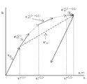
- the relationship between the proposed analysis method and the time history response analysis method that gives an exact solution is shown in FIG. The following two assumptions were used to construct this analysis method.
- the first is an assumption for deriving the equation of motion that is the basis of the analysis method
- the second is an assumption for performing response spectrum analysis. .
- (1) When the mode is expanded in the natural vibration mode of the elastic response, the interaction between the modes occurs when the rigidity is lowered due to the elastic-plastic response, but this is ignored.
- (2) Since only the maximum response of each mode can be obtained from the constant plastic modulus response spectrum, a mode superposition rule is assumed for mode superposition similarly to the response spectrum analysis of a linear multi-degree-of-freedom system.
- the proposed analysis method is used, the maximum response of each mode can be grasped from the constant plastic modulus response spectrum used in the analysis, so the prediction of the degree of influence that the natural period of the system and changes in the ground motion have on the analysis results is excellent.
- the elasto-plastic response characteristics of each mode with respect to the floor response due to an earthquake have been confirmed as elasto-plastic response characteristics of a one-degree-of-freedom system (Non-Patent Document 9). Therefore, it is easy to give conservativeness to the constant plastic modulus response spectrum used for the design and conservative setting of analysis parameters such as the yield strength of the system used for the design. I think that it is effective to use it for seismic design. From now on, the proposed response spectrum analysis method for nonlinear multi-degree-of-freedom system is called elasto-plastic response spectrum analysis method, and the conventional response spectrum analysis method for linear multi-degree-of-freedom system is called elastic response spectrum analysis method.
- linear response analysis can be used as a simple method of nonlinear response analysis.
- This linear response analysis as a simple method of nonlinear response analysis has the meaning that linear response analysis is used in the current seismic design in that it guarantees that conservative results can be obtained from nonlinear response analysis.
- an acceptance criterion applied to the result of nonlinear response analysis can be applied.
- Non-Patent Document 10 A condition for determining whether the response of the corresponding linear system is larger than that of the nonlinear system is proposed.
- a linear system corresponding to the nonlinear system will be described later.
- a y ⁇ n 2 x y is the yield acceleration of the system.
- ⁇ of the system is determined by four parameters: a y , for a given external force F (t), It can be seen that it is determined by T n , h, and ⁇ .
- x max is the maximum deformation
- ⁇ k ′ / k is the stiffness ratio.
- the one-degree-of-freedom system considered in this specification is a non-linear one-degree-of-freedom system having a stiffness ratio range of 0 ⁇ ⁇ ⁇ 1 and a corresponding linear one-degree-of-freedom system.
- the corresponding linear single-degree-of-freedom system is a system in which the mass, initial rigidity, damping ratio, and yield point are equal to those of the non-linear single-degree-of-freedom system and the rigidity ratio is 1, and even if the deformation exceeds the yield deformation It is a virtual system whose rigidity does not decrease.
- a nonlinear one-degree-of-freedom system is a system in which the rigidity decreases when the deformation exceeds the yield deformation, but a corresponding linear one-degree-of-freedom system can be considered as a system in which the rigidity decrease is minimized.
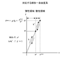
- the nonlinear one-degree-of-freedom system and the corresponding linear one-degree-of-freedom system correspond to FIGS. 2A and 2B, respectively, and both are inelastic systems having a yield point. Therefore, both the nonlinear one-degree-of-freedom system and the corresponding linear one-degree-of-freedom system can express the maximum response of the system using the plasticity ratio indicating the magnitude of the maximum deformation of the system with reference to the yield deformation.
- the plasticity ratio ⁇ is usually used for a system that makes an elastic-plastic response ( ⁇ > 1), but can also be used for a system that responds elastically (0 ⁇ ⁇ ⁇ 1).
- the constant plasticity rate response spectrum indicates the yield acceleration ay of the one-degree-of-freedom system with the damping ratio h and the rigidity ratio ⁇ applied by the external force F (t) with respect to a specific plasticity ratio ⁇ . This is illustrated as a function a y (T n , h, ⁇ , ⁇ ) of the natural period T n .
- the yield strength f y of the system the use of certain ductility factor response spectrum, the natural period of the system, the damping ratio, from ductility factor that allows the rigidity ratio and systems, yield strength necessary for the system Can be obtained. Further, the plasticity ratio generated in the system can be obtained from the yield strength, natural period, damping ratio, and rigidity ratio of the system.
- the constant plastic modulus response spectrum is also referred to as a necessary yield spectrum and is often used in the former, but in this specification, the latter is used.
- the acceleration response spectrum A (T n , h) illustrates the maximum response acceleration A of a linear single-degree-of-freedom system with a damping ratio h on which an external force F (t) acts as a function of the natural period T n .
- This elastic response spectrum a e (T n , h) matches the acceleration response spectrum A (T n , h) as follows: (Strictly speaking, the elastic response spectrum matches the pseudo acceleration response spectrum. The pseudo acceleration response spectrum and the acceleration response spectrum are approximately equal (Non-patent Document 3).)
- the constant plastic modulus response spectrum is usually drawn for a system that has an elasto-plastic response in which the plastic modulus ⁇ is greater than 1, but can also be drawn for a system that has an elastic response with a plastic modulus ⁇ of 1 or less.
- the response of the system that stops at the elastic response is a linear response, and the response of a virtual system that responds to an elasto-plastic response but does not decrease in rigidity after yielding is also a linear response.
- A is the maximum response acceleration
- a e is the yield acceleration required for the elastic system
- a y is the system yield acceleration
- h is the system damping ratio
- T n is the natural period of the system
- xy is The yield deformation amount of the system
- x max is the maximum deformation amount
- ⁇ is the plasticity factor
- ⁇ n is the natural angular frequency of the system.
- the results obtained from the elastic response spectrum analysis method and the elasto-plastic response spectrum analysis method are in accordance with the equation (9).
- the elasto-plastic response spectrum analysis method uses the elasto-plastic response spectrum analysis method to analyze the time history response analysis of a nonlinear one-degree-of-freedom system, regardless of whether the yield acceleration a y of the system exceeds or falls below the yield acceleration a e required for an elastic system
- the plasticity factor ⁇ is obtained, and from this, the maximum deformation of the system can be obtained.
- Elasto-plastic response spectrum analysis method for nonlinear multi-degree-of-freedom system The constant plastic modulus response spectrum gives the maximum response of the system in the form of the plastic modulus continuously from the elastic response to the elasto-plastic response by giving the natural period and the yield acceleration of the elastic response of the system with one degree of freedom.
- a conventional elastic response spectrum analysis method is an analysis method in which the maximum response acceleration of each mode is read from the acceleration response spectrum and the maximum response of the system is obtained using the mode superposition rule based on these equations.
- the authors developed a mode of a nonlinear N-degree-of-freedom system, and used the newly defined mode yield displacement and mode yield acceleration in the mode coordinate system for time-dependent mode plasticity in the form of equations (5) and (6).
- the equations of motion of N independent single-degree-of-freedom systems were obtained. Based on these equations, we have developed a method to obtain the maximum response of the system using the mode superposition rule by reading the mode plastic modulus of each mode from the constant plastic modulus response spectrum.
- the developed elasto-plastic response spectrum analysis method is shown below.
- An N-degree-of-freedom displacement vector ⁇ X ⁇ can be expressed by the following equation as a mode superposition.
- Equation (12) the equation of motion of mode coordinates ⁇ q ⁇ is obtained as follows.
- ⁇ r , h r , and ⁇ r are the r-order mode angular frequency, mode damping ratio, and stimulation coefficient, respectively.
- the deformation of the spring i 1 -j 1 is the yield deformation
- the first breakdown occurs in the nonlinear N-degree-of-freedom system.
- the deformation of the spring i 2 -j 2 is the yield deformation
- a second yielding occurs in the system.
- the yielding of the system advances and the nth yielding occurs at the spring i n -j n .
- the equation of motion in which the n points of the nonlinear N-degree-of-freedom system yield and are in the plastic region is as follows. here,
- Equation (18) The n + 1 terms after the third term on the left side of Equation (18) represent the restoring force of the system where n places yielded.
- the mode yield displacement q r y (ij) of the spring ij is introduced, and the definition is as follows.
- Equation of motion of nonlinear multi-degree-of-freedom system without interaction between modes The equation of motion (22) in the plastic region of the mode coordinate ⁇ q ⁇ obtained in the previous section is s ⁇ r in the sum of the third term on the left side.
- a certain N ⁇ 1 terms represents the interaction between the r-th mode and other modes.
- the yielded springs i 1 -j 1 to springs i n -j n are not yielded by only the response of the r- th mode, but by the total response obtained by superimposing the responses of the respective modes, And surrendered.
- the displacement of the nonlinear N-degree-of-freedom system due to the r-order mode is given by ⁇ r ⁇ r ⁇ r ⁇ .
- ⁇ r is increased from 0, the deformation of the spring i 1 r -j 1 r The first surrender occurs in the system.
- the deformation of the spring i 2 r -j 2 r is the yield deformation
- the second surrender of the system occurs.
- the yield of the system advances, and the n'th yield occurs at the spring i n ' r -j n' r .
- the equation of motion in which the n ′ part of the nonlinear N-degree-of-freedom system yields and is in the plastic region is as follows.
- (I o j o ) represents a spring that yields due to the superposition of responses of all modes
- (i o r j o r ) represents a spring that yields due to a response of only the r th mode
- each mode of the mode coordinate ⁇ has a restoring force characteristic in which the load / mode displacement relationship is a polylinear skeleton curve and follows the kinematic hardening law.
- the polyline skeleton curve is approximated by a bilinear skeleton curve having an elastic stiffness of K ⁇ r and a secondary stiffness of K ′′ ⁇ r as shown in FIG. ) Yields: here,
- Equations (17) and (28) are expressed as ⁇ r.
- ⁇ r max can be obtained by convergence calculation to give max .
- equations (17) and (28) The equation of motion of the time-dependent mode plasticity ratio D r (t) is obtained as follows. here, Is the mode yield acceleration.
- D r (t) and a r y are respectively the time-dependent mode plasticity rate and mode yield acceleration of the spring i 1 r -j i r that yields first in the r-th order, which is simply the r-th order time-dependent mode plasticity. Called rate and mode yield acceleration.
- Expressions (30) and (31) have the same format as expressions (5) and (6). Therefore, the r-th order mode plasticity ratio ⁇ r can be obtained from the mode yield acceleration a r y and the natural period T r using a constant plastic ratio response spectrum of the mode damping ratio h r and the mode rigidity ratio ⁇ r .
- Time-dependent plasticity index D ij x i -x j / x ij y spring ij from the definition formula for modal displacements (21), and r next time the spring ij dependent mode ductility factor D r ij It turns out that there is the following relationship.
- the plasticity ratio ⁇ ij max ⁇
- ⁇ of the spring ij can be obtained as follows.
- the elasto-plastic response spectrum analysis method of the nonlinear multi-degree-of-freedom system developed by the inventors.
- This analysis method is derived using the assumption that there is no interaction between modes in the plastic region and the assumption of the mode superposition rule. Yes, it can be said that the response spectrum analysis method of the linear multi-degree-of-freedom system is extended to the response spectrum analysis method of the non-linear multi-degree-of-freedom system using the constant plastic modulus response spectrum.
- the load / mode displacement relationship approximated a multi-line skeleton curve with a bi-line skeleton curve.
- Non-Patent Document 9 Since the difference in the quadratic stiffness of the bilinear skeleton curve does not significantly affect the constant plastic modulus response spectrum (Non-Patent Document 9), it is considered that the influence on the analysis result of the bilinear skeleton curve used for the analysis is small.
- 8A and 8B show how to determine the maximum deformation of a multi-degree-of-freedom system by the elastic response spectrum analysis method and the elasto-plastic response spectrum analysis method.
- the plastic modulus of the spring ij is It becomes.
- a r is the maximum response acceleration in the r-order mode
- a r e is the yield acceleration of the r-order mode required for the elastic system
- a r y is the r-order mode yield acceleration of the system
- h r is the system r-th order mode damping ratio
- i, j are mass point numbers (1... N)
- r is mode order (1...
- T r is the r-th natural period of the system
- x i r is The displacement of the mass point i in the r-th mode
- x ij max is the maximum deformation amount of the spring ij
- x ij y is the yield deformation amount of the spring ij
- ⁇ r is the stimulation coefficient of the r-order mode
- ⁇ r is the stiffness coefficient of the r-order mode
- ⁇ r y (ij) is the displacement of the r-order mode when the spring ij yields
- spring i 1 r -j 1 r is the r order mode displacement is that of the spring to yield initially in the system.
- mu ij is ductility factor of the spring ij
- mu r is r order mode ductility factor
- ⁇ phi r ⁇ is the order r of the system
- the natural mode, ⁇ r, is the r-order natural angular frequency of the system.
- the results obtained from the elastic response spectrum analysis method and the elasto-plastic response spectrum analysis method are in accordance with the equation (9).
- elastoplastic response spectrum analysis method when the mode yield acceleration a r y of the system exceeds the yield acceleration a e required for an elastic system, in any of the cases below, the time history of the non-linear single degree of freedom system response mode ductility factor mu r from a certain ductility factor response spectrum created obtained by analysis, it is possible to determine the than the maximum deformation of each mode this.
- Nonlinear system based on floor response and corresponding plasticity of linear system A condition for determining whether the plasticity rate of a linear system corresponding to a floor response due to an earthquake is larger than that of a nonlinear system with one degree of freedom has been confirmed (Non-Patent Document 10). Using this one-degree-of-freedom system judgment condition, the condition for judging whether the plasticity rate of the corresponding linear system is larger than the multi-degree-of-freedom nonlinear system for the floor response due to an earthquake will be examined.
- One-degree-of-freedom plastic modulus An elastic-plastic response is caused by a floor response caused by an earthquake, that is, the yield acceleration a y is The plasticity factor ⁇ of a linear single-degree-of-freedom system corresponding to the plasticity factor ⁇ Compare The yield acceleration a y and the natural period T n of the nonlinear one-degree-of-freedom system are When Holds. This relationship is obtained from the analysis of the constant plastic modulus response spectrum (hereinafter referred to as the constant plastic modulus floor response spectrum) to the floor response of the structure and the elastic response spectrum (hereinafter referred to as the elastic floor response spectrum) to the floor response of the structure. (Non-Patent Document 10).
- the constant plastic modulus response spectrum hereinafter referred to as the constant plastic modulus floor response spectrum
- the elastic response spectrum hereinafter referred to as the elastic floor response spectrum
- T s is the primary natural period of the structure that supports the one-degree-of-freedom system
- ⁇ (a y ) is an assumed load coefficient defined by the following expression for the one-degree-of-freedom system that is equal to or less than the first natural period of the structure.
- F 0 max ⁇ F (t) ⁇ is the maximum external force value
- a 0 is the maximum response acceleration of the building floor.
- the assumed load coefficient ⁇ (a y ) is the assumed load with respect to the maximum external force F 0 Represents the ratio.
- the assumed load represents the magnitude of the load when it is assumed that the same plasticity factor as that of the linear one degree of freedom system corresponding to the nonlinear one degree of freedom system is generated. That assume the load factor is greater than 1, means that the load acting on the system by the response is assumed to amplify the external force maximum value F 0, the size is indicative of the degree of amplification of the assumed load.
- Plastic modulus of the corresponding linear single-degree-of-freedom system Is given by: here, Is a spectrum in which the elastic floor response spectrum a e (T n , h) is widened in the short axis direction of the periodic axis with a widening ratio ⁇ (> 0), and the plastic modulus Is Is a plasticity ratio generated in the corresponding linear single-degree-of-freedom system by the floor response corresponding to. From FIG. 4, the constant plastic modulus floor response spectrum having a plastic modulus ⁇ larger than 1 tends to be larger on the short period side than the long period side in the response amplification region of the elastic floor response spectrum (for example, 0 in FIG. 4).
- Non-Patent Document 10 the expansion of the elastic floor response spectrum a e (T n , h) in the short axis direction of the periodic axis is to cope with this.
- the inventors examined a constant plastic modulus floor response spectrum of earthquake observation records, and recommended 1.5 and 0.1 as the threshold value ⁇ and the widening rate ⁇ of the assumed load coefficient, respectively (Non-Patent Document 10).
- the region above the elastic floor response spectrum is an elastic response region
- the region below the elastic response spectrum is an elastic-plastic response region.
- the elastoplastic response region is divided into region I and region II according to the condition of equation (38).
- the region I satisfying the condition of the equation (38) indicates the response amplification region of the elastic floor response spectrum and the long-period region longer than the primary natural period of the structure, and the system in this region is It becomes.
- the system in the region II excluding the region close to the boundary with the region I is It becomes.
- the assumed load is the yield strength fy .
- the elastic response is caused by the floor response due to the earthquake, that is, the yield acceleration a y is
- the response of the one-degree-of-freedom system is a linear response, and the plasticity ratio ⁇ is given by the equation (10), so the equation (39) is satisfied.
- Plasticity of multi-degree-of-freedom system The relationship between the plasticity ratio of a nonlinear system with one degree of freedom and the corresponding linear system is applied to the relationship between the modal plasticity ratio of the nonlinear system with multiple degrees of freedom and the corresponding linear system. From equations (37) to (42), the mode yield acceleration a r y and the natural period T r are determined as Is satisfied, the r-th order mode plasticity ratio ⁇ r of the nonlinear multi-degree-of-freedom system is the r-th order mode plasticity ratio of the corresponding linear multi-degree-of-freedom system. It becomes as follows. That is, Holds.
- the corresponding linear multi-degree-of-freedom system is a system in which each non-linear spring of the non-linear multi-degree-of-freedom system is a spring whose rigidity does not decrease after yielding, that is, a spring having a stiffness ratio of 1, and its mode plasticity ratio Is given by:
- the r-th order mode plasticity ratio ⁇ r ij of the spring ij of the nonlinear multi-degree-of-freedom system is expressed as follows. It becomes as follows.
- the elasto-plastic response spectrum analysis method gives an analysis result with good accuracy, it is possible to determine whether the plasticity rate of the corresponding linear system is larger than that of the multi-degree-of-freedom nonlinear system according to the determination condition of Equation (43). it can. If this determination condition is valid, a linear response analysis of a multi-degree-of-freedom system can be used as a simple method of a non-linear response analysis of a multi-degree-of-freedom system when this determination condition is satisfied.
- Dynamic Response Analysis of Nonlinear Two-Degree-of-Freedom System for Floor Response> Suggested allowable plastic ratios for designing equipment and piping systems are 1.2 to 2 for heavy equipment, 1.5 to 3 for piping systems, and 2.5 to 10 for steel material tension and bending. (Non-patent Document 8). Assuming that the elasto-plastic response spectrum analysis method is applied to the dynamic response analysis of a system that generates this degree of plasticity, the elasticity of the nonlinear two-degree-of-freedom system with respect to the floor response is evaluated. It is calculated by the plastic response spectrum analysis method and the time history response analysis method. In addition, the plastic modulus of the corresponding linear two-degree-of-freedom system is calculated by an elastic response spectrum analysis method using an elastic floor response spectrum with a widening ratio ⁇ 0.1.
- Non-linear two-degree-of-freedom system for analysis model and condition analysis is a system in which two mass points are combined with non-linear springs and with each other or the floor. Suppose that it has a restoring force characteristic that follows the law.
- the external force is the floor response of the Tottori-ken Seibu Earthquake (NS-) observed at the Shimane Nuclear Power Station Unit 2 reactor building (primary natural period T s : 0.21 s , secondary natural period: 0.13 s) shown in Fig. 3.
- 2R / Bch24 is multiplied by a factor, and the natural period of the analysis model is added to the constant plastic modulus floor response spectrum of the floor response (NS-2R / Bch24) as shown in Fig. 12.
- Model A is the primary mode of the building
- the model B has a natural period in the region where the floor response is greatly amplified by the primary mode of the building (the peak region of the spectrum), and Model B has a region where the floor response is greatly amplified by the primary and secondary modes of the building (spectrum).
- Model C is a system having a natural period in a region where the amplification of the floor response is small and the floor response is small (the valley region of the spectrum).
- EP-RSA bar graph and dotted line with bar
- E-RSA solid line and alternate long and short dashed line
- RHA double dotted line with bar
- the plasticity factor obtained is shown.
- the first-order and second-order mode plasticity ratios obtained from the elastoplastic response spectrum analysis are shown in black and white in the bar graph, respectively.
- the SRS rule is used to indicate the plasticity rate as a dotted line with a bar.
- the plastic modulus obtained from the elastic response spectrum analysis is a straight line
- the plastic modulus using the mode superposition rule as an absolute value sum rule is indicated by a solid line
- the plastic modulus using the mode superposition rule as an SRSS rule is indicated by a one-dot chain line.
- the plasticity ratio is smaller in value based on the SRSS rule than the value obtained using the mode superposition rule as the absolute value sum rule.
- EL indicates an external force at which the system becomes an elastic limit
- EL ⁇ 1.5, 2, 3, 6 indicates an external force that is 1.5, 2, 3, 6 times the external force at which the system becomes an elastic limit, respectively.
- the secondary assumed load coefficient ⁇ 2 ⁇ (a 2 y ) for Model A
- the primary assumed load coefficient ⁇ having a smaller value among the primary and secondary assumed load coefficients for Models B and C. 1 ⁇ (a 1 y ) is indicated by a dotted line with white circles in the Spring2-2 diagram of each model.
- the primary natural period of Model A is T s ⁇ T 1 and is in a period band that does not define an assumed load coefficient.
- Model A and B show that the plastic modulus of each spring obtained from the time history response analysis is smaller than the plastic modulus obtained from the elastic response spectrum analysis. There is a tendency for the increase in the plasticity rate to be small. This can be understood because Models A and B have a natural period in a region where floor response amplification is large, and the effect of hysteresis attenuation is large.
- Model C the plastic ratio of each spring obtained from the time history response analysis is larger than the plastic ratio obtained from the elastic response spectrum analysis, and the increase in the plastic ratio with respect to the increase in seismic force tends to be large. This can be understood because Model C is a system having a natural period in a region where the floor response amplification is small and the effect of hysteresis damping is small.
- the absolute value sum rule gives a value greater than the response value of time history response analysis.
- the plastic modulus of each spring using the absolute value sum rule in the elasto-plastic response spectrum analysis of the nonlinear multi-degree-of-freedom system is generally higher than the plastic modulus obtained from the time history response analysis, but some of them are lower. This is considered to be an effect assuming that there is no interaction between the modes used in the construction of this analysis method.
- the minimum value of the ratio of plasticity in the elasto-plastic response spectrum analysis (mode superposition rule: absolute value sum rule) for time history response analysis is 0.97 (Spring2-2, EL x 1.5) for Model A, Model B 0.84 (Spring2-2, EL ⁇ 6) and 0.73 (Spring2-2, EL ⁇ 3) for Model C.
- the elasto-plastic response spectrum analysis (mode superposition law: absolute value sum rule, SRSS law) of the nonlinear two-degree-of-freedom system implemented in this chapter is the following analysis model, analysis conditions, and analysis results
- mode superposition rule absolute value sum rule, SRSS rule
- the calculation result of the plasticity ratio may be non-conservative up to about 30%.
- the system vibrates with an external force up to 6 times the external force that is the elastic limit.
- Models A, B, and C are systems that each have a natural period in a characteristic region of the floor response spectrum.
- These analysis results include a response that yields one spring, a response that yields two springs, and a response that yields all three springs (4)
- the system has a plasticity ratio up to the upper limit applicable to seismic design.
- the elastic-plastic response spectrum analysis method is considered to be effective as a dynamic response analysis method for equipment and piping systems used in seismic design.
- the primary assumed load coefficient ⁇ 1 is 1. Less than 5 and smaller than other analysis cases. Also, in the analysis cases of Model A and B (Spring2-2, EL ⁇ 6), the plastic modulus of the elasto-plastic response spectrum analysis becomes smaller than that of the time history response analysis as the assumed load factor decreases. Tend.
- the elastic response spectrum analysis gives a larger plasticity than the elastoplastic response spectrum analysis (comparison using the same mode superposition rule), and the time history response analysis It can be seen that the elastic response spectrum analysis gives a large plasticity ratio.
- the mode superposition rule is slightly smaller than the plastic rate of the time history response analysis. This is considered to be an influence of the accuracy of the SRSS rule.
- the inventors have developed an elastic-plastic response spectrum analysis method as a dynamic response analysis method for nonlinear multi-degree-of-freedom systems.
- This analysis method is an extension of the elastic response spectrum analysis method, which is a dynamic response analysis method for linear multi-degree-of-freedom systems, to a dynamic response analysis method for nonlinear multi-degree-of-freedom systems using a constant plastic modulus response spectrum. It is based on the equation of motion of the nonlinear one-degree-of-freedom system for the newly defined time-dependent mode plasticity.
- the results of dynamic response analysis using a elasto-plastic response spectrum analysis method and a time history response analysis method for a nonlinear two-degree-of-freedom system in which the load-deformation relationship is a bilinear skeleton curve are consistent with certain accuracy.
- the elasto-plastic response spectrum analysis method is considered to be effective as a dynamic response analysis method for a multi-degree-of-freedom system that responds to elasto-plastic response and to understand the response of such a system from the mode concept of the elastic region.
- the inventors have proposed a determination condition that can determine whether the plasticity rate of a corresponding linear system is larger than that of a multi-degree-of-freedom nonlinear system.
- a linear response analysis of a multi-degree-of-freedom system can be used as a simple method of a non-linear response analysis of a multi-degree-of-freedom system.
- equipment and piping systems are hypothetical systems whose rigidity does not decrease after yielding in seismic design, that is, they are generally treated as linear systems and their responses are obtained by linear response analysis. In many cases, it is an overly conservative seismic design. If seismic design by this method becomes possible, rational seismic design that takes into account the hysteresis damping that occurs in the system will be possible.
- This analysis method is applicable not only to seismic response analysis, but also to dynamic response analysis in general for nonlinear multi-degree-of-freedom systems.
Landscapes
- Engineering & Computer Science (AREA)
- Physics & Mathematics (AREA)
- Theoretical Computer Science (AREA)
- Computer Hardware Design (AREA)
- Evolutionary Computation (AREA)
- Geometry (AREA)
- General Engineering & Computer Science (AREA)
- General Physics & Mathematics (AREA)
- Measurement Of Mechanical Vibrations Or Ultrasonic Waves (AREA)
Abstract
計算コストが比較的低い一方で、解析の精度が比較的高い非線形多自由度系の動的応答解析法を提供する。 塑性領域におけるモード間の相互作用を無視し、モードの重ね合わせにモード重ね合わせ則を仮定した上で、弾性領域の固有振動モードにより非線形多自由度系をモード展開して、非線形一自由度系の時刻歴応答解析により作成した一定塑性率応答スペクトルから得たモード塑性率を用いることにより、各モードの最大変形を把握する。
Description
本発明は、非線形多自由度系の動的応答解析法に関する。より詳しくは、本発明は、一定塑性率応答スペクトルを用いた非線形多自由度系の動的応答解析法に関する。
地震等により弾塑性応答する機器・配管系の応答は、非線形多自由度系の応答解析により求める必要がある。非線形多自由度系の応答解析法には、応答の厳密解が得られる「直接積分法による時刻歴応答解析法」と簡易法である「等価線形化法を用いた応答スペクトル解析法」が代表的である。簡易法である「等価線形化法を用いた応答スペクトル解析法」は、系の弾塑性応答による剛性の低下と履歴減衰を、等価な線形剛性と線形減衰とで表わすことにより、非線形多自由度系をそれと等価な線形多自由度系に置き換え、線形多自由度系の応答スペクトル解析法を用いる方法である。「等価線形化法を用いた応答スペクトル解析法」については、例えば、特許文献1及び2に、等価な線形剛性と線形減衰の与え方の例が記載されている。
Caughey, T. K., Sinusoidal excitation of a system with bilinear hysteresis, Journal of Applied Mechanics, ASME, Vol.27 (1960a), pp.640-643.
Caughey, T. K., Random excitation of a system with bilinear hysteresis, Journal of Applied Mechanics, ASME, Vol.27 (1960b), pp.649-652.
Chopra, A. K., Dynamics of Structures, 4th ed. (2011), pp.244-245, pp. 276-278, Prentice Hall, New Jersey, USA.
飯島唯司、 小野悟、 等価線形化法による配管系の簡易的な弾塑性地震応答解析、 日本機械学会論文集、 C編、 Vol.68,No.673(2002), pp.2542-2548.
Iwan, W. D. and Gates, N. C., Estimating Earthquake Response of simple hysteretic structures, Journal of the Engineering Mechanics Division, ASCE, Vol.105, No.3 (1979), pp391-405.
Jennings, P. C., Equivalent Viscous Damping for yielding structures, Proceedings of ASCE, Vol.94 (1968), pp.103-116.
浪田芳郎、 川畑淳一、 市橋一郎、 福田俊彦、 弾塑性ダンパ支持配管系の耐震設計手法の開発 : 第3報, 三次元配管モデル試験とその応答解析、 日本機械学会論文集 C編、 Vol.61, No.590(1995), pp.3881-3888.
Newmark, N. M., Inelastic design of nuclear reactor structures and its implication on design of critical equipment, Proceedings of International Conference on Structural Mechanics in Reactor Technology(1977), K 4/1.
田村伊知郎、 松浦真一、 地震力に対する機器・配管系の弾塑性応答評価法(一自由度系の弾塑性応答特性の考察、 日本機械学会論文集、 Vol.82, No.835 (2016), DOI:10.1299/transjsme.15・00467.
Tamura, I., Matsuura, S. and Shimazu, R., Yield strength reduction factor of nonlinear SDOF systems on the supporting structures, Proceedings of the ASME 2016 Pressure Vessels and Piping Conference (2016), Canada, PVP2016・63944.
Veletsos, A. S. and Newmark, N. M., Effect of inelastic behavior on the response of simple systems to earthquake motions, Proceedings of the 2nd World Conference on Earthquake Engineering, Vol.2 (1960), pp.895-912.
しかし、「直接積分法による時刻歴応答解析法」は、厳密解が得られるものの、機器・配管系を非線形の有限要素モデルにより詳細にモデル化する必要があるため、非線形有限要素モデルの直接積分法による解析は、多くの計算量を必要とし、計算コストが大きなものとなる。
また、「等価線形化法を用いた応答スペクトル解析法」は、非線形多自由度系を等価な線形多自由度系に置き換えるため、「直接積分法による時刻歴応答解析法」に比較して、計算コストは少なくなるものの、その精度は明らかではない。
このため、非線形多自由度系の地震応答解析は、これまで、機器・配管系の耐震設計において実用化されておらず、線形多自由度系の地震応答解析法が用いられているのが現状である。
本発明は、上記課題に鑑みてなされたものであり、計算コストが比較的低い一方で、解析の精度が比較的高い非線形多自由度系の動的応答解析法を提供することを目的とする。
本発明は、塑性領域におけるモード間の相互作用を無視し、モードの重ね合わせにモード重ね合わせ則を仮定した上で、弾性領域の固有振動モードにより非線形多自由度系をモード展開して、非線形一自由度系の時刻歴応答解析により作製した一定塑性率応答スペクトルから得たモード塑性率を用いることにより、各モードの最大変形を把握する、非線形多自由度系の動的応答解析法に関する。
更に、多自由度の非線形系に比べ、対応する線形系の塑性率が大きくなるか判定し、非線形応答解析の簡易法として、線形応答解析を用いることが好ましい。
また、上記の非線形多自由度系の動的応答解析法は、非線形多自由度系において、r次のモード変位によりばねi1
r-j1
rから、ばねin
r-jn
rまで順次降伏する際、r次の各振動数をωr、r次のモード降伏変位を

、刺激係数をβrとしたとき、

によって算出されるr次のモード降伏加速度が、r次の固有周期をTr、減衰比をhrとしたときの弾性応答スペクトルae(Tr,hr)以上であることを実施条件とすることが好ましい。
また、上記の非線形多自由度系の動的応答解析法は、線形一自由度系の塑性率を、

、剛性比をγr、構築物床の最大応答加速度をA0としたとき、構築物の一次固有周期以下の一自由度系に対して、

によって定義される想定荷重係数ε(ar
y)が、閾値α以上であることを実施条件とすることが好ましい。
また、上記の非線形多自由度系の動的応答解析法は、系を支持する構築物の一次固有周期をTs、非線形多自由度系のr次の固有周期をTrとしたとき、Ts≦Trであることを実施条件とすることが好ましい。
本発明により、計算コストが低い一方で、解析の精度が高い非線形多自由度系の動的応答解析法を提供することが可能となる。
<1.発明の概要>
耐震設計において、機器・配管系は降伏後も剛性が低下しない仮想的な系、即ち、線形系として扱いその応答を線形応答解析により求めることが一般的である。線形多自由度系の応答解析法には、時刻歴応答解析法と応答スペクトル解析法がある。前者は系の最大応答の厳密解が得られるが、解析パラメータの変化が解析結果に及ぼす影響程度の予見性がない。後者は各モードが最大応答となる同時性について仮定し、モード重ね合わせ則を用いることにより系の最大応答が得られるため、厳密解は得られないが、解析に用いる加速度応答スペクトルから各モードの最大応答が把握でき、解析パラメータの変化が解析結果に及ぼす影響程度の予見性に優れている。また、加速度応答スペクトルへの保守性の付与も容易であり、機器・配管系の耐震設計においては、応答スペクトル解析法が広く用いられている。
耐震設計において、機器・配管系は降伏後も剛性が低下しない仮想的な系、即ち、線形系として扱いその応答を線形応答解析により求めることが一般的である。線形多自由度系の応答解析法には、時刻歴応答解析法と応答スペクトル解析法がある。前者は系の最大応答の厳密解が得られるが、解析パラメータの変化が解析結果に及ぼす影響程度の予見性がない。後者は各モードが最大応答となる同時性について仮定し、モード重ね合わせ則を用いることにより系の最大応答が得られるため、厳密解は得られないが、解析に用いる加速度応答スペクトルから各モードの最大応答が把握でき、解析パラメータの変化が解析結果に及ぼす影響程度の予見性に優れている。また、加速度応答スペクトルへの保守性の付与も容易であり、機器・配管系の耐震設計においては、応答スペクトル解析法が広く用いられている。
弾塑性応答する機器・配管系を線形系として扱うと解析は容易になるが、系に生じる履歴減衰や塑性変形による固有周期の変化が考慮できない等の課題がある。弾塑性応答する機器・配管系を実現象に即して降伏後に剛性が低下する系、即ち非線形として扱うと、その応答を非線形応答解析により求める必要がある。非線形多自由度系の応答解析法にも、時刻歴応答解析法と応答スペクトル解析法があるが、次に述べる課題がある。前者は系の最大応答の厳密解が得られるが、線形系と同じく解析パラメータの変化が解析結果に及ぼす影響程度の予見性がない。後者の代表例に等価線形化法を用いた応答スペクトル解析法がある。この解析法は系の弾塑性応答による剛性の低下と履歴減衰を、等価な線形剛性と線形減衰で表し、加速度応答スペクトルを用いて応答スペクトル解析を行う方法である。等価な線形剛性と線形減衰の与え方は幾つかの提案がなされているが、厳密解を与える時刻歴応答解析法との理論的な関係は明らかでない(非特許文献1、5、及び6)。
発明者らは、機器・配管系の耐震設計に用いる弾塑性応答評価法を提案する。発明者らは、既に、その第一段階として、一定塑性率応答スペクトル(Constant ductility response spectrum)を分析し、地震による床応答に対する一自由度系の弾塑性応答特性について報告した(非特許文献9)。本明細書では、その第二段階として、一定塑性率応答スペクトルを用いる非線形多自由度系の応答スペクトル解析法を提案する。一定塑性率応答スペクトルは、応答により非線形一自由度系に生じる塑性率を、ある特定の値に止めるために必要な系の降伏耐力が簡単に得られるスペクトルである(非特許文献11)。弾塑性応答スペクトルの一つであるこの応答スペクトルには、以下の特徴がある。
(1)一自由度系の弾塑性応答は、剛性の低下や履歴減衰の影響を含め応答解析により厳密に計算されている。
(2)一自由度系の弾性応答の固有周期を横軸としており、弾塑性応答の程度に係わらず着目する系の弾性応答の固有周期により、応答スペクトル上で着目する周期を特定できる。
(3)一自由度系の降伏耐力(又はこれを系の質量で除した降伏加速度)を縦軸としており、これを与えることにより、弾性応答から弾塑性応答まで連続的に系の最大応答を塑性率という形で与える。
(1)一自由度系の弾塑性応答は、剛性の低下や履歴減衰の影響を含め応答解析により厳密に計算されている。
(2)一自由度系の弾性応答の固有周期を横軸としており、弾塑性応答の程度に係わらず着目する系の弾性応答の固有周期により、応答スペクトル上で着目する周期を特定できる。
(3)一自由度系の降伏耐力(又はこれを系の質量で除した降伏加速度)を縦軸としており、これを与えることにより、弾性応答から弾塑性応答まで連続的に系の最大応答を塑性率という形で与える。
非線形多自由度系の等価線形化法を用いた応答スペクトル解析法は、非線形多自由度系を等価な線形多自由度系に置き換え、これをモード展開して線形一自由度系の応答解析の結果を用いるものである(非特許文献4及び7)。これに対し、提案する非線形多自由度系の応答スペクトル解析法は、非線形系から線形系への置き換えを行わず、非線形多自由度系をモード展開して非線形一自由度系の応答解析の結果を用いるものである。提案する解析法と厳密解を与える時刻歴応答解析法の関係を図1に示す。この解析法の構築に当たり用いた仮定は以下の二つであり、一つ目は解析法の基礎となる運動方程式を導出するための仮定、二つ目は応答スペクトル解析を行うための仮定である。
(1)弾性応答の固有振動モードでモード展開すると、弾塑性応答により剛性が低下した際にはモード間の相互作用を生じるが、これを無視する。
(2)一定塑性率応答スペクトルからは各モードの最大応答のみ得られるため、線形多自由度系の応答スペクトル解析と同様に、モードの重ね合わせにモード重ね合わせ則を仮定する。
(1)弾性応答の固有振動モードでモード展開すると、弾塑性応答により剛性が低下した際にはモード間の相互作用を生じるが、これを無視する。
(2)一定塑性率応答スペクトルからは各モードの最大応答のみ得られるため、線形多自由度系の応答スペクトル解析と同様に、モードの重ね合わせにモード重ね合わせ則を仮定する。
提案する解析法を用いると、解析に用いる一定塑性率応答スペクトルから各モードの最大応答が把握できるため、系の固有周期や地震動の変化が解析結果へ及ぼす影響程度の予見性に優れている。また、地震による床応答に対する各モードの弾塑性応答特性は、一自由度系の弾塑性応答特性として確認されている(非特許文献9)。従って、設計に用いる一定塑性率応答スペクトルへの保守性の付与や設計に用いる系の降伏耐力等の解析パラメータの保守的な設定が容易であり、この解析法を弾塑性応答する機器・配管系の耐震設計に用いることは有効であると考える。これ以降、提案する非線形多自由度系の応答スペクトル解析法を弾塑性応答スペクトル解析法といい、従来の線形多自由度系の応答スペクトル解析法を弾性応答スペクトル解析法という。
弾塑性応答する機器・配管系を実現象に即して非線形系として扱うと、その応答を非線形応答解析により求める必要があるが、非線形応答解析より線形応答解析の結果が保守的である条件が明らかであれば、非線形応答解析の簡易法として線形応答解析を用いることができる。この非線形応答解析の簡易法としての線形応答解析は、非線形応答解析より保守的な結果が得られることを担保している点で、現在の耐震設計において線形応答解析を用いていることと意味合いが異なる。非線形応答解析の簡易法としての線形応答解析の結果に対しては、非線形応答解析の結果に対して適用する許容基準を適用することができる。著者らは、一自由度の非線形系に比べ、対応する線形系の応答が大きくなるか判定する条件を明らかにしており(非特許文献10)、この知見に基づき、本報では多自由度の非線形系に比べ、対応する線形系の応答が大きくなるか判定する条件を提案する。非線形系に対応する線形系については後述する。
<2.一自由度系の弾塑性応答と一定塑性率応答スペクトル>
2.1 一自由度系の運動方程式
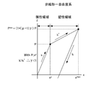
荷重・変形関係が二直線骨格曲線であり移動硬化則に従う復元力特性をもつ一自由度系を考える。応答が弾性領域にある系の運動方程式は次式となる。

ここで、xは変形、mは質量、cは減衰係数、kは初期剛性、tは時間、F(t)は外力、xyは降伏変形である。
2.1 一自由度系の運動方程式
荷重・変形関係が二直線骨格曲線であり移動硬化則に従う復元力特性をもつ一自由度系を考える。応答が弾性領域にある系の運動方程式は次式となる。
変形xが降伏変形xyを超えると、系が降伏する。応答が塑性領域にある系の運動方程式は次式となる。

ここで、kは二次剛性である。
式(1)、(2)を質量mで除すと次式が得られる。
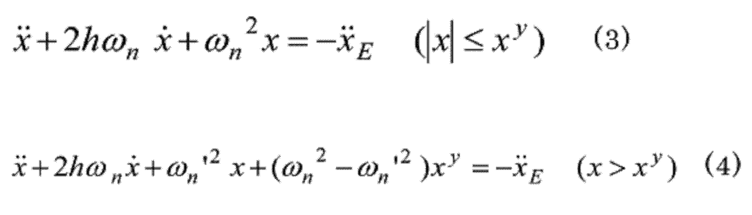
ここで、

は固有角振動数、

は二次剛性に対応した固有角振動数、

は減衰比、

は入力加速度である。
式(3)、(4)を降伏変形xyで除すと、系の時間依存塑性率D=x/xyに対する運動方程式が次の通り得られる。


ここで、ay=ωn
2xyは系の降伏加速度である。
式(5)、(6)より、系の塑性率μ=xmax/xy=max{|D(t)|}は、与えられた外力F(t)に対し4つのパラメータ:ay、Tn、h、γにより定まることがわかる。ここで、xmaxは最大変形、Tn=2π/ωnは固有周期、γ=k’/kは剛性比である。
本明細書で考える一自由度系は、剛性比の範囲が0≦γ<1の非線形一自由度系及びこれに対応する線形一自由度系とする。ここで、対応する線形一自由度系とは、非線形一自由度系と質量、初期剛性、減衰比及び降伏点が等しく、剛性比を1とした系であり、変形が降伏変形を超えても剛性が低下しない仮想的な系である。非線形一自由度系は変形が降伏変形を超えると剛性が低下する系であるが、対応する線形一自由度系はこの剛性低下が極限まで小さくなった系と考えることができる。非線形一自由度系及び対応する線形一自由度系は、各々、図2A及び図2Bが該当し、いずれも降伏点を有する非弾性系である。従って、非線形一自由度系及び対応する線形一自由度系ともに、降伏変形を基準に系の最大変形の大きさを表す塑性率を用いて系の最大応答を表すことができる。このように、降伏点を持つ仮想的な線形一自由度系という概念を導入することにより、非線形一自由度系と対応する線形一自由度系の塑性率による応答の比較が可能となる。なお、塑性率μは、通常、弾塑性応答する系に対して用いる(μ>1)が、弾性応答する系に対しても用いる(0≦μ<1)ことができる。
2.2 一定塑性率応答スペクトル
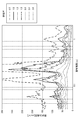
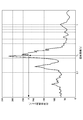
一定塑性率応答スペクトルは、外力F(t)が作用する減衰比h、剛性比γの一自由度系の降伏加速度ayを、特定の塑性率μに対して固有周期Tnの関数ay(Tn,h,γ,μ)として図示するものである。この図は、固有周期Tn毎に、外力F(t)が作用する減衰比h、剛性比γの一自由度系に対して降伏加速度を変化させ時刻歴応答解析を行い、その応答が特定の塑性率μとなる系の降伏加速度ayを収束計算により求め、作成する(非特許文献3)。島根原子力発電所2号機原子炉建物で観測した鳥取県西部地震の床応答を図3に、この一定塑性率応答スペクトルを図4に示す。なお、式(5)、(6)より、系の降伏加速度ayと入力加速度

には次式の関係があり、一定塑性率応答スペクトルは系の降伏加速度に代えて入力加速度を変化させて計算することもできる。

一定塑性率応答スペクトルは、外力F(t)が作用する減衰比h、剛性比γの一自由度系の降伏加速度ayを、特定の塑性率μに対して固有周期Tnの関数ay(Tn,h,γ,μ)として図示するものである。この図は、固有周期Tn毎に、外力F(t)が作用する減衰比h、剛性比γの一自由度系に対して降伏加速度を変化させ時刻歴応答解析を行い、その応答が特定の塑性率μとなる系の降伏加速度ayを収束計算により求め、作成する(非特許文献3)。島根原子力発電所2号機原子炉建物で観測した鳥取県西部地震の床応答を図3に、この一定塑性率応答スペクトルを図4に示す。なお、式(5)、(6)より、系の降伏加速度ayと入力加速度
系の降伏耐力fyとするとfy=mayであるため、一定塑性率応答スペクトルを用いると、系の固有周期、減衰比、剛性比及び系に許容する塑性率から、系に必要な降伏耐力を得ることができる。また、系の降伏耐力、固有周期、減衰比及び剛性比から、系に生じる塑性率を得ることができる。一定塑性率応答スペクトルは必要耐力スペクトルともいわれ、前者の使い方をすることが多いが、本明細書では後者の使い方をする。
一定塑性率応答スペクトルay(Tn,h,γ,μ)と加速度応答スペクトルA(Tn,h)の関係を考える。加速度応答スペクトルA(Tn,h)は、外力F(t)が作用する減衰比hの線形一自由度系の最大応答加速度Aを、固有周期Tnの関数として図示するものである。系が弾性に止まるために必要な降伏加速度aeは,塑性率μ=1の一定塑性率応答スペクトルにより与えられる。このスペクトルを次式の通り弾性応答スペクトルae(Tn,h)と定義する。

この弾性応答スペクトルae(Tn,h)は、次式の通り加速度応答スペクトルA(Tn,h)に一致する。(厳密には弾性応答スペクトルは疑似加速度応答スペクトルと一致する。疑似加速度応答スペクトルと加速度応答スペクトルは近似的に等しい(非特許文献3)。)

一定塑性率応答スペクトルは、通常、塑性率μが1より大きい弾塑性応答する系に対して描くが、塑性率μが1以下の弾性応答に止まる系に対しても描くことができる。弾性応答に止まる系の応答は線形応答であり、また、弾塑性応答するが降伏後も剛性が低下しない仮想的な系の応答も線形応答である。系が弾性に止まるために必要な降伏加速度ae=ωn
2xmaxと系の降伏加速度ay=ωn
2xyを用いると、線形応答する系の塑性率μ=xmax/xyは次式で与えられる。

従って、線形応答する系の一定塑性率応答スペクトルay(Tn,γ,h;μ)は、弾性応答スペクトルae(Tn,h)を用いて次式で与えられる。

2.3 応答スペクトル解析法
弾性応答スペクトル解析法と弾塑性応答スペクトル解析法による一自由度系の最大変形の求め方を図5A及び図5Bを用いて示す。
弾性応答スペクトル解析法と弾塑性応答スペクトル解析法による一自由度系の最大変形の求め方を図5A及び図5Bを用いて示す。
まず、弾性応答スペクトル解析法について説明する。図5Aのグラフは、加速度応答スペクトルを示す。このスペクトルより、最大加速度A=A(Tn,h)が得られる。更に、最大加速度Aから、最大変形量xmax=A/ωn
2が得られる。
次に、弾塑性応答スペクトル解析法について説明する。図5Bのグラフは、一定塑性率応答スペクトルを示す。このスペクトルより、塑性率μ=μ(ay,Tn,h,γ)が得られる。更に、この塑性率μから、最大変形量xmax=μxyが得られる。仮に系が線形であれば、
xmax=μxy=(ae/ay)xy=ae/(ωn 2)
となる。ここで、式(11)よりμ=ae/ayである。
xmax=μxy=(ae/ay)xy=ae/(ωn 2)
となる。ここで、式(11)よりμ=ae/ayである。
なお、Aは最大応答加速度、aeは、弾性系に必要とされる降伏加速度、ayは系の降伏加速度、hは、系の減衰比、Tnは系の固有周期、xyは、系の降伏変形量、xmaxは最大変形量、μは塑性率、ωnは系の固有角振動数である。
系が線形である場合、式(9)より弾性応答スペクトル解析法と弾塑性応答スペクトル解析法から得られる結果は一致する。弾塑性応答スペクトル解析法を用いると、系の降伏加速度ayが弾性系であるために必要な降伏加速度aeを上回る場合、下回る場合のいずれにおいても、非線形一自由度系の時刻歴応答解析により作成した一定塑性率応答スペクトルから塑性率μが得られ、これより系の最大変形を求めることができる。
<3.非線形多自由度系の弾塑性応答スペクトル解析法>
一定塑性率応答スペクトルは、一自由度系の弾性応答の固有周期と降伏加速度を与えることにより、弾性応答から弾塑性応答まで連続的に系の最大応答を塑性率という形で与える。この優れた特性を有する一定塑性率応答スペクトルを用いる非線形多自由度系の応答スペクトル法を考える。
一定塑性率応答スペクトルは、一自由度系の弾性応答の固有周期と降伏加速度を与えることにより、弾性応答から弾塑性応答まで連続的に系の最大応答を塑性率という形で与える。この優れた特性を有する一定塑性率応答スペクトルを用いる非線形多自由度系の応答スペクトル法を考える。
線形N自由度系をモード展開すると、式(3)の形式のモード変位に対する独立したN個の線形一自由度系の運動方程式が得られる。これらの式に基づき、各モードの最大応答加速度を加速度応答スペクトルから読み取り、モード重ね合わせ則を用いて系の最大応答を求める解析法が、従来の弾性応答スペクトル解析法である。著者らは、非線形N自由度系をモード展開し、モード座標系において新たに定義したモード降伏変位及びモード降伏加速度を用いて、式(5)、(6)の形式の時間依存モード塑性率に対する独立したN個の非線形一自由度系の運動方程式を得た。これらの式に基づき、各モードのモード塑性率を一定塑性率応答スペクトルから読み取り、モード重ね合わせ則を用いて系の最大応答を求める方法を開発した。開発した弾塑性応答スペクトル解析法を以下に示す。
3.1 線形多自由度系のモード展開
N個の質点を線形ばねで、互いに又は床と結合した線形N自由度系を考える。質点iの質量をmi、質点i-j間のばねi-jの剛性をkijとすると、この系の運動方程式は次式となる(i,j=1,2・・・N)。ただし、質点i-i間のばねi-iは質点iと床の間のばねを表す。

ここで、


{X}は変位ベクトル、[M]は質量行列、[C]は減衰行列、[K]は剛性行列、

は外力F(t)の加速度ベクトルを示す。
N個の質点を線形ばねで、互いに又は床と結合した線形N自由度系を考える。質点iの質量をmi、質点i-j間のばねi-jの剛性をkijとすると、この系の運動方程式は次式となる(i,j=1,2・・・N)。ただし、質点i-i間のばねi-iは質点iと床の間のばねを表す。
ここで、行列の各列が系の固有角振動数ωiに対応する固有振動モード[Φ]i={φi}である行列[Φ]を定義する。N自由度系の変位ベクトル{X}はモードの重ね合わせとして、次式で表すことができる。

式(12)と(15)より、モード座標{q}の運動方程式が次のように得られる。

ここで、ωr,hr,βrは,各々r次のモード角振動数、モード減衰比及び刺激係数である。
式(16)をβrで除すとモード座標{η}の運動方程式が次のように得られる。ここで、ηr=qr/βrである。

3.2 非線形多自由度系のモード展開
前節の線形N自由度系のばねを非線形ばねとした非線形N自由度系を考える。非線形ばねは、荷重・変形関係が二直線骨格曲線であり移動硬化則に従う復元力特性を持つとする。一例として非線形N自由度系のモデル図を図6に示す。応答が弾性領域である系の運動方程式は、式(12)、(16)及び(17)に等しい。次に、非線形N自由度系の応答が弾性領域から塑性領域に入り、ばねi1-j1からばねin-jnでまで順次降伏する運動を考える。この運動は、ばねi-jの降伏変形をxij y、降伏したばねの二次剛性をk’ijとすると、以下のように記述することができる。
前節の線形N自由度系のばねを非線形ばねとした非線形N自由度系を考える。非線形ばねは、荷重・変形関係が二直線骨格曲線であり移動硬化則に従う復元力特性を持つとする。一例として非線形N自由度系のモデル図を図6に示す。応答が弾性領域である系の運動方程式は、式(12)、(16)及び(17)に等しい。次に、非線形N自由度系の応答が弾性領域から塑性領域に入り、ばねi1-j1からばねin-jnでまで順次降伏する運動を考える。この運動は、ばねi-jの降伏変形をxij y、降伏したばねの二次剛性をk’ijとすると、以下のように記述することができる。
ばねi1-j1の変形が降伏変形

となり非線形N自由度系に最初の降伏が生じる。次にばねi2-j2の変形が降伏変形

となり系に2番目の降伏が生じる。そして、系の降伏が進みn番目の降伏がばねin-jnで生じる。このとき、非線形N自由度系のn箇所が降伏し塑性領域にある運動方程式は次式となる。
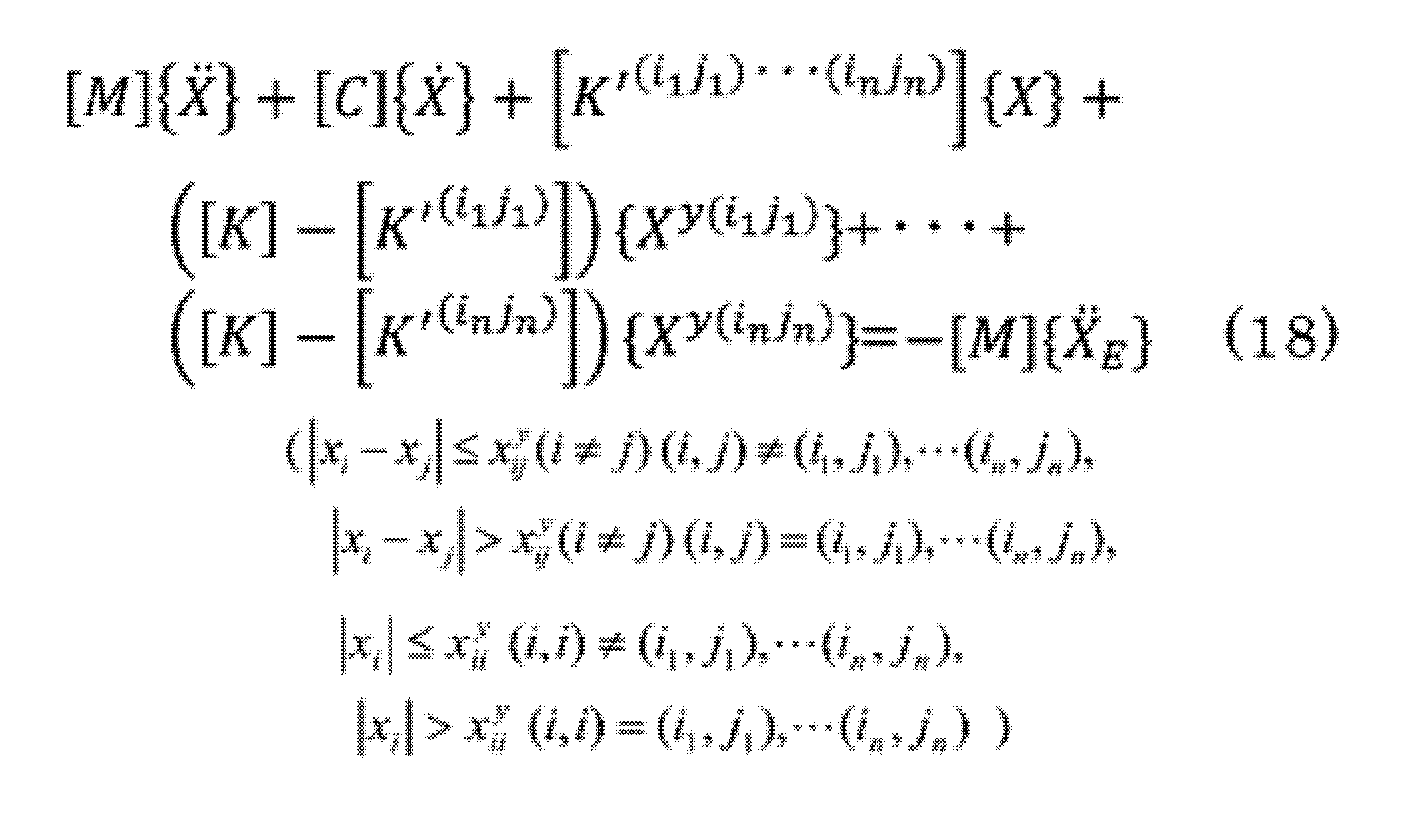
ここで、


式(18)の左辺の第3項以降のn+1個の項が、n箇所が降伏した系の復元力を表す。モード座標{q}において、ばねi-jのモード降伏変位qr
y(ij)を導入することとし、その定義は次式とする。

r次のモード変位がqr
y(ij)となると、r次の固有振動モード{φr}の変位によりばねi-jが降伏する。式(18)に式(15)を代入し、式(18)の各項に前から{Φ}Tを乗じて式(21)を用いると、モード座標{q}の運動方程式が次のように得られる。
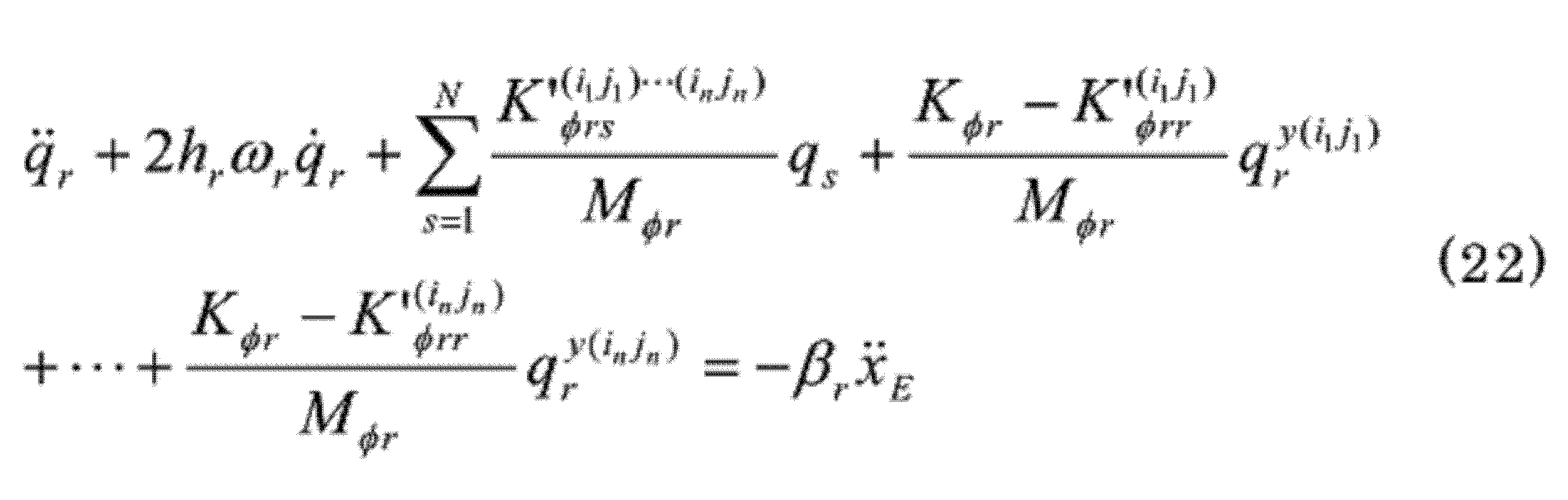
ここで、

である。
3.3 モード間の相互作用のない非線形多自由度系の運動方程式
前節で得たモード座標{q}の塑性領域の運動方程式(22)は、左辺第3項の総和のうちs≠rであるN-1個の項が、r次モードと他のモードの相互作用を表す。また、降伏したばねi1-j1からばねin-jnは、r次モードの応答のみにより降伏したものではなく、各モードの応答を重ね合わせた全応答により、各ばねがその降伏変位となり降伏したものである。
前節で得たモード座標{q}の塑性領域の運動方程式(22)は、左辺第3項の総和のうちs≠rであるN-1個の項が、r次モードと他のモードの相互作用を表す。また、降伏したばねi1-j1からばねin-jnは、r次モードの応答のみにより降伏したものではなく、各モードの応答を重ね合わせた全応答により、各ばねがその降伏変位となり降伏したものである。
最初に、モード間の相互作用を陽に含まないモード座標{q}の運動方程式を得るために次式の仮定をする。

この仮定を用いると、式(22)よりモード座標{q}の運動方程式が次のように得られる。

ここで、ωr
2=Kφr/Mφr、

である。
式(25)をβrで除すと、モード座標{η}の運動方程式が次のように得られる。ここで、

である。
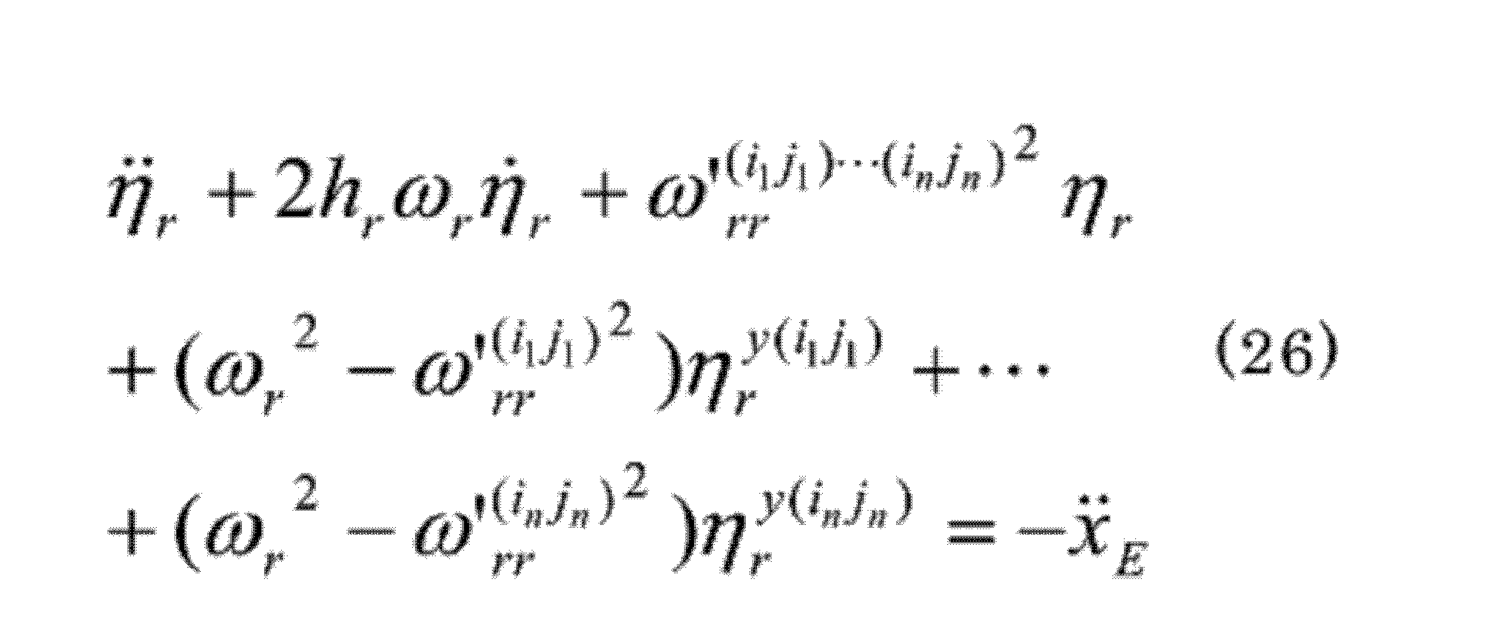
次に、r次モードのみ運動する非線形N自由度系を仮想的に考える。この系の応答が弾性領域から塑性領域に入り、ばねi1
r-j1
rからばねin
r-jn
rまで順次降伏する運動を考えると、この運動は以下のように記述することができる。
r次モードによる非線形N自由度系の変位はηrβr{φr}で与えられる。ηrを0から大きくすると、ばねi1
r-j1
rの変形が降伏変形

となり系に最初の降伏が生じる。次にばねi2
r-j2
rの変形が降伏変形

となり系の2番目の降伏が生じる。そして、系の降伏が進みn’番目の降伏がばねin’
r-jn’
rで生じる。非線形N自由度系のn’箇所が降伏し塑性領域にある運動方程式は次式となる。
式(26)と(27)において、(iojo)と(io
rjo
r)は各々系のうちo番目に降伏が生じるばねを表す。(iojo)は全てのモードの応答の重ね合わせにより降伏が生じるばねを表すのに対し、(io
rjo
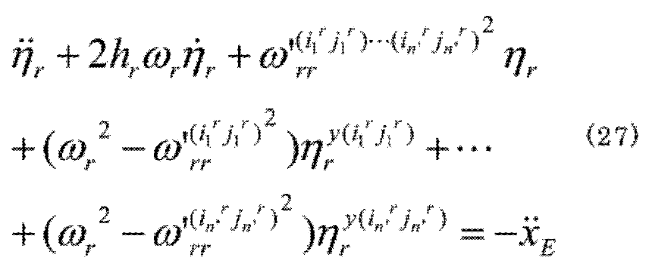
r)はr次モードのみの応答により降伏が生じるばねを表すため、両式は一般に等しくないが、式(26)をモード間の相互作用がない、即ち各モードの運動を独立して規定する式(27)に置き換えることとする。
式(27)より、モード座標{η}の各モードは、荷重・モード変位関係が多直線骨格曲線であり移動硬化則に従う復元力特性を持つことがわかる。この復元力特性を単純化するため、多直線骨格曲線を図7に示すように弾性剛性がKφrで二次剛性がK”φrである二直線骨格曲線で近似する。この近似により式(27)から次式が得られる。

ここで、

ηr
max=max{|ηr(t)|}はr次のモード変位ηrの最大値で、K”φrはηr
maxの関数となる。式(17)と(28)がηr
maxを与えるためηr
maxは収束計算により得ることができる。時間依存モード塑性率を

とすると、式(17)と(28)を

で除すと、時間依存モード塑性率Dr(t)の運動方程式が次の通り得られる。


ここで、

はモード降伏加速度である。Dr(t)とar
yは各々r次で最初に降伏するばねi1
r-ji
rの時間依存モード塑性率とモード降伏加速度であるが、これを単にr次の時間依存モード塑性率とモード降伏加速度という。
3.4 弾塑性応答スペクトル解析法
式(30)、(31)より、ある外力に対するr次のモード塑性率μr=max{|Dr(t)|}は次式で表される。

ここで、
である。
式(30)、(31)より、ある外力に対するr次のモード塑性率μr=max{|Dr(t)|}は次式で表される。
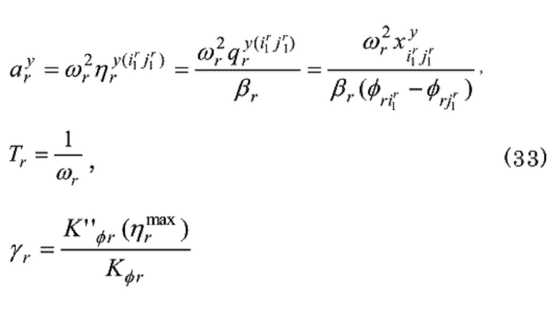
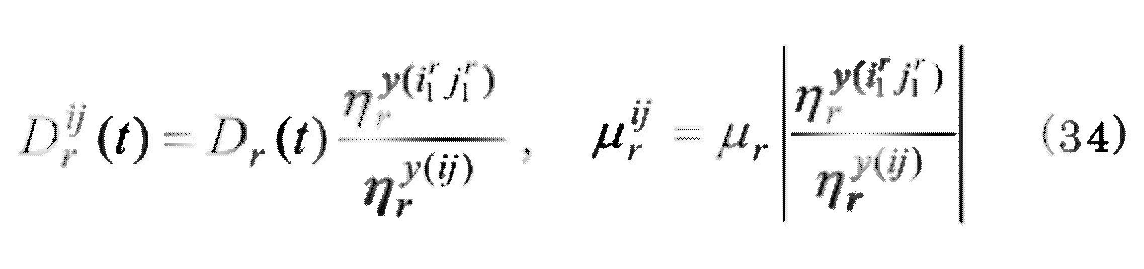
式(30)と(31)は式(5)と(6)と同じ形式である。従って、r次のモード塑性率μrは、モード減衰比hr、モード剛性比γrの一定塑性率応答スペクトルを用いて、モード降伏加速度ar
yと固有周期Trから得ることができる。ばねi-rのr次の時間依存モード塑性率Dr
ij(t)=ηr(t)/ηr
y(ij)及びモード塑性率μr
ij=max{|Dr
ij(t)|}は、

より次式で表すことができる。
ばねi-jの時間依存塑性率Dij=xi-xj/xij
yは、モード変位の定義式(21)から、ばねi-jのr次の時間依存モード塑性率Dr
ijと次の関係にあることがわかる。
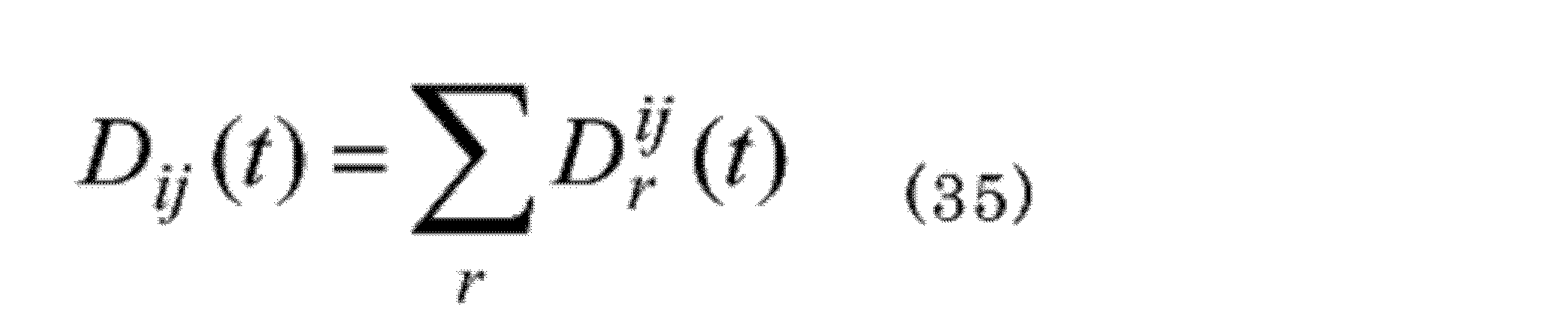
従って、モード重ね合わせ則を用いると、ばねi-jの塑性率μij=max{|Dij(t)|}は次の通り得ることができる。

以上が、発明者らが開発した非線形多自由度系の弾塑性応答スペクトル解析法である。この解析法は、弾性領域の固有振動モードにより非線形多自由度系をモード展開し、塑性領域においてもモード間の相互作用がないとの仮定及びモード重ね合わせ則の仮定を用いて導出したものであり、線形多自由度系の応答スペクトル解析法を、一定塑性率応答スペクトルを用いて非線形多自由度系の応答スペクトル解析法に拡張したものといえる。また、解析に用いる一定塑性率応答スペクトルにあわせて、荷重・モード変位関係は多直線骨格曲線を二直線骨格曲線で近似した。二直線骨格曲線の二次剛性の違いは一定塑性率応答スペクトルにさほど大きな影響を与えないため(非特許文献9)、解析に用いる二直線骨格曲線の解析結果への影響は小さいと考える。
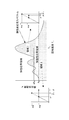
弾性応答スペクトル解析法と弾塑性応答スペクトル解析法による多自由度系の最大変形の求め方を図8A及び図8Bを用いて示す。
まず、弾性応答スペクトル解析法について説明する。図8Aのグラフは、加速度応答スペクトルを示す。このスペクトルより、r次の最大加速度Ar=A(Tr,hr)が得られる。更に、r次の最大加速度Arからr次のモードでの質点iの変位xi
r=(Arβrφri)/ωr
2が得られる。また、モード重ね合わせ則により、ばねi-jの最大変形量

が得られる。
次に、弾塑性応答スペクトル解析法について説明する。図8Bのグラフは、一定塑性率応答スペクトルを示す。このスペクトルより、r次モードの塑性率μr=μ(ar
y,Tr,hr,γr)が得られる。更に、この塑性率μrから、ばねi-jのr次モードの塑性率

が得られる。
モード重ね合わせ則により、ばねi-jの塑性率は、

となる。
塑性率μijから、ばねi-jの最大変形量

が得られる。
仮に系が線形であるなら、

となる。ここで、式(11)より、

である。
なお、Arはr次モードでの最大応答加速度、ar
eは弾性系に必要とされるr次モードの降伏加速度、ar
yは系のr次のモード降伏加速度、hrは系のr次のモード減衰比、i,jは質点の番号(1・・・N)、rはモードの次数(1・・・N)、Trは系のr次の固有周期、xi
rはr次モードにおける質点iの変位、xij
maxは、ばねi-jの最大変形量、xij
yはばねi-jの降伏変形量、

は、モード重ね合わせ則、βrは、r次モードの刺激係数、γrはr次モードの剛性率、ηr
y(ij)は、ばねi-jの降伏時におけるr次モードの変位、

は、ばねi1
r-j1
rの降伏時におけるr次モードの変位であり、ばねi1
r-j1
rは、r次モード変位により、系において最初に降伏するばねのことである。また、μijは、ばねi-jの塑性率、μrはr次のモード塑性率、μr
ijはばねi-jのr次のモード塑性率、{φr}は系のr次の固有モード、ωrは系のr次の固有角振動数である。
系が線形である場合、式(9)より弾性応答スペクトル解析法と弾塑性応答スペクトル解析法から得られた結果は一致する。弾塑性応答スペクトル解析法を用いると、系のモード降伏加速度ar
yが弾性系であるために必要な降伏加速度aeを上回る場合、下回る場合のいずれにおいても、非線形一自由度系の時刻歴応答解析により作成した一定塑性率応答スペクトルからモード塑性率μrが得られ、これより各モードの最大変形を求めることができる。
<4.床応答による非線形系と対応する線形系の塑性率>
地震による床応答に対して、一自由度の非線形系より対応する線形系の塑性率が大きくなるか判定する条件が確認されている(非特許文献10)。この一自由度系の判定条件を用い、地震による床応答に対して、多自由度の非線形系より対応する線形系の塑性率が大きくなるか判定する条件を検討する。
地震による床応答に対して、一自由度の非線形系より対応する線形系の塑性率が大きくなるか判定する条件が確認されている(非特許文献10)。この一自由度系の判定条件を用い、地震による床応答に対して、多自由度の非線形系より対応する線形系の塑性率が大きくなるか判定する条件を検討する。
4.1 一自由度系の塑性率
地震による床応答により弾塑性応答する、即ち、降伏加速度ayが

である非線形一自由度系の塑性率μと対応する線形一自由度系の塑性率

を比較する。非線形一自由度系の降伏加速度ay及び固有周期Tnが

であるとき、

が成り立つ。この関係は、構築物の床応答に対する一定塑性率応答スペクトル(以下、一定塑性率床応答スペクトルという)と構築物の床応答に対する弾性応答スペクトル(以下、弾性床応答スペクトルという)を分析した結果から得られたものである(非特許文献10)。ここで、Tsは一自由度系を支持する構築物の一次固有周期、ε(ay)は構築物の一次固有周期以下の一自由度系に対して、次式で定義する想定荷重係数である。

ここで、F0=max{F(t)}は外力最大値、A0は構築物床の最大応答加速度である。
地震による床応答により弾塑性応答する、即ち、降伏加速度ayが
想定荷重係数ε(ay)は、外力最大値F0に対する想定荷重

の比を表す。想定荷重は、非線形一自由度系に対応する線形一自由度系と同じ塑性率が生じると想定した場合の荷重の大きさを表す。想定荷重係数が1より大きいということは、応答により系に作用する荷重が外力最大値F0から増幅すると想定されることを意味し、その大きさが想定荷重の増幅の程度を表す。対応する線形一自由度系の塑性率

は次式で与えられる。

ここで、

は、弾性床応答スペクトルae(Tn,h)を拡幅率Δ(>0)で周期軸短周期方向に拡幅したスペクトルであり、塑性率

は

に相当する床応答により、対応する線形一自由度系に生じる塑性率である。図4より、塑性率μが1より大きい一定塑性率床応答スペクトルは、弾性床応答スペクトルの応答増幅領域のうち長周期側に比べ短周期側で大きくなる傾向があり(例えば、図4の0.2s付近)、弾性床応答スペクトルae(Tn,h)の周期軸短周期方向への拡幅はこれに対応するためのものである。発明者らは地震観測記録の一定塑性率床応答スペクトルを検討し、想定荷重係数の閾値 α及び拡幅率Δとして各々1.5及び0.1を推奨した(非特許文献10)。
式(38)の条件を満たす弾完全塑性型の系(γ=0)の領域を図9の一定塑性率床応答スペクトル上に示す。この図で、弾性床応答スペクトルより上の領域は弾性応答領域であり、弾性応答スペクトルより下の領域は弾塑性応答領域である。弾塑性応答領域は、式(38)の条件により領域Iと領域IIに区分される。式(38)の条件を満たす領域Iは、弾性床応答スペクトルの応答増幅領域及び構築物の一次固有周期より長周期領域を示しており、この領域にある系は

となる。一方、領域Iとの境界に近い領域を除く領域IIにある系は

となる。また、剛性比γの系は想定荷重が降伏耐力fyの

倍となるため、図9の領域Iと領域IIの境界は

となる。
なお、地震による床応答により弾性応答する、即ち、降伏加速度ayが

である一自由度系の応答は線形応答であり、その塑性率μは式(10)により与えられるため式(39)を満たす。
4.2 多自由度系の塑性率
一自由度の非線形系と対応する線形系の塑性率の関係を、多自由度の非線形系と対応する線形系のモード塑性率の関係に当てはめる。式(37)から(42)より、モード降伏加速度ar y及び固有周期Trが次の判定条件

を満足するとき、非線形多自由度系のr次のモード塑性率μrは対応する線形多自由度系のr次のモード塑性率

以下となる。即ち、

が成り立つ。ここで、対応する線形多自由度系とは、非線形多自由度系の各非線形ばねを降伏後も剛性が低下しないばね、即ち剛性比1のばねとした系であり、そのモード塑性率

は次式で与えられる。

一自由度の非線形系と対応する線形系の塑性率の関係を、多自由度の非線形系と対応する線形系のモード塑性率の関係に当てはめる。式(37)から(42)より、モード降伏加速度ar y及び固有周期Trが次の判定条件
このとき、非線形多自由度系のばねi-jのr次のモード塑性率μr
ijは、次式に示す通り、対応する線形多自由度系のばねi-jのr次のモード塑性率

以下となる。
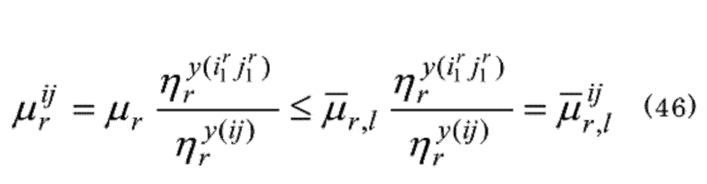
以上より、各モードの固有周期Tr及びモード降伏加速度ar
yが式(43)の判定条件を満たすとき、非線形多自由度系の弾塑性応答スペクトル解析法により得られるばねi-jの塑性率は、次式に示す通り、対応する線形多自由度系の弾性応答スペクトル解析により得られるばねi-jの塑性率以下となる。

従って、弾塑性応答スペクトル解析法がよい精度で解析結果を与える場合、式(43)の判定条件により、多自由度の非線形系より、対応する線形系の塑性率が大きくなるか判定することができる。この判定条件が有効であれば、この判定条件を満たす場合、多自由度系の線形応答解析を多自由度系の非線形応答解析の簡易法として用いることができる。
<5.床応答に対する非線形二自由度系の動的応答解析>
機器・配管系の設計に適用する許容塑性率として、重量機器に対し1.2~2、配管系に対し1.5~3、鋼材の引張りと曲げに対して2.5~10等が提案されている(非特許文献8)。この程度の塑性率を生じる系の動的応答解析に、弾塑性応答スペクトル解析法を適用することを想定し、その有効性を確認するため、床応答に対する非線形二自由度系の塑性率を弾塑性応答スペクトル解析法及び時刻歴応答解析法により計算する。また、対応する線形二自由度系の塑性率を、拡幅率Δ=0.1の弾性床応答スペクトルを用いて弾性応答スペクトル解析法により計算する。
機器・配管系の設計に適用する許容塑性率として、重量機器に対し1.2~2、配管系に対し1.5~3、鋼材の引張りと曲げに対して2.5~10等が提案されている(非特許文献8)。この程度の塑性率を生じる系の動的応答解析に、弾塑性応答スペクトル解析法を適用することを想定し、その有効性を確認するため、床応答に対する非線形二自由度系の塑性率を弾塑性応答スペクトル解析法及び時刻歴応答解析法により計算する。また、対応する線形二自由度系の塑性率を、拡幅率Δ=0.1の弾性床応答スペクトルを用いて弾性応答スペクトル解析法により計算する。
5.1 解析モデルと条件
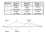
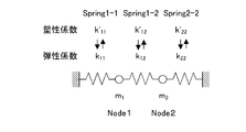
解析する非線形二自由度系は、2個の質点を非線形ばねで、互いに又は床と結合した系とし、非線形ばねは荷重・変形関係が二直線骨格曲線であり移動硬化則に従う復元力特性を持つとする。解析モデルと固有振動モード及びモデル図を図10、11に示す(m1=m2=1kg,k11=k12=k,k22=2k,f11 y=f12 y=f22 y=2N,γ=0.2,h=0.02)。外力は、図3に示す島根原子力発電所2号機原子炉建物(1次固有周期Ts:0.21s,2次固有周期:0.13s)で観測した鳥取県西部地震の床応答(NS-2R/Bch24を係数倍したものとした。床応答(NS-2R/Bch24)の一定塑性率床応答スペクトルに解析モデルの固有周期を追記した図を図12に示す。Model Aは建物の一次モードを超えた領域および建物の一次モードにより床応答の増幅が大きい領域(スペクトルの山領域)に固有周期を持つ系、Model Bは建物の一次及び二次モードにより床応答の増幅が大きい領域(スペクトルの山領域)に固有周期を持つ系、Model Cは建物の振動モードから外れ床応答の増幅が小さい領域(スペクトルの谷領域)に固有周期を持つ系である。これらのモデルで最初に降伏するばねは一次モード、二次モード共に、Spring2-2である。
解析する非線形二自由度系は、2個の質点を非線形ばねで、互いに又は床と結合した系とし、非線形ばねは荷重・変形関係が二直線骨格曲線であり移動硬化則に従う復元力特性を持つとする。解析モデルと固有振動モード及びモデル図を図10、11に示す(m1=m2=1kg,k11=k12=k,k22=2k,f11 y=f12 y=f22 y=2N,γ=0.2,h=0.02)。外力は、図3に示す島根原子力発電所2号機原子炉建物(1次固有周期Ts:0.21s,2次固有周期:0.13s)で観測した鳥取県西部地震の床応答(NS-2R/Bch24を係数倍したものとした。床応答(NS-2R/Bch24)の一定塑性率床応答スペクトルに解析モデルの固有周期を追記した図を図12に示す。Model Aは建物の一次モードを超えた領域および建物の一次モードにより床応答の増幅が大きい領域(スペクトルの山領域)に固有周期を持つ系、Model Bは建物の一次及び二次モードにより床応答の増幅が大きい領域(スペクトルの山領域)に固有周期を持つ系、Model Cは建物の振動モードから外れ床応答の増幅が小さい領域(スペクトルの谷領域)に固有周期を持つ系である。これらのモデルで最初に降伏するばねは一次モード、二次モード共に、Spring2-2である。
5.2 解析結果
ModelA,B及びCの塑性率の計算結果を図13A~13Cに示す。EP-RSA(棒グラフとバー付き点線)、E-RSA(実線と一点鎖線)及びRHA(バー付き二点鎖線)は、各々、弾塑性応答スペクトル解析、弾性応答スペクトル解析及び時刻歴応答解析から得られた塑性率を示す。弾塑性応答スペクトル解析から得られた一次と二次のモード塑性率を各々棒グラフの黒と白で示しており、モード重ね合わせ則を絶対値和則とした塑性率は積み重ね棒グラフで、モード重ね合わせ則をSRSS則とした塑性率はバー付き点線で示す。弾性応答スペクトル解析から得られた塑性率は直線であり、モード重ね合わせ則を絶対値和則とした塑性率は実線で、モード重ね合わせ則をSRSS則とした塑性率は一点鎖線で示す。塑性率はモード重ね合わせ則を絶対値和則とした値よりSRSS則とした値が小さい。また、ELは系が弾性限界となる外力を示し、EL×1.5,2,3,6は系が弾性限界となる外力の各々1.5,2,3,6倍の外力を示す。あわせて、Model Aについては2次の想定荷重係数ε2=ε(a2 y)を、ModelB,Cについては1次と2次の想定荷重係数のうち値が小さい1次の想定荷重係数ε1=ε(a1 y)を、各ModelのSpring2-2の図に白丸付き点線で示した。なお、Model Aの1次固有周期はTs<T1であり想定荷重係数を定義していない周期帯にある。
ModelA,B及びCの塑性率の計算結果を図13A~13Cに示す。EP-RSA(棒グラフとバー付き点線)、E-RSA(実線と一点鎖線)及びRHA(バー付き二点鎖線)は、各々、弾塑性応答スペクトル解析、弾性応答スペクトル解析及び時刻歴応答解析から得られた塑性率を示す。弾塑性応答スペクトル解析から得られた一次と二次のモード塑性率を各々棒グラフの黒と白で示しており、モード重ね合わせ則を絶対値和則とした塑性率は積み重ね棒グラフで、モード重ね合わせ則をSRSS則とした塑性率はバー付き点線で示す。弾性応答スペクトル解析から得られた塑性率は直線であり、モード重ね合わせ則を絶対値和則とした塑性率は実線で、モード重ね合わせ則をSRSS則とした塑性率は一点鎖線で示す。塑性率はモード重ね合わせ則を絶対値和則とした値よりSRSS則とした値が小さい。また、ELは系が弾性限界となる外力を示し、EL×1.5,2,3,6は系が弾性限界となる外力の各々1.5,2,3,6倍の外力を示す。あわせて、Model Aについては2次の想定荷重係数ε2=ε(a2 y)を、ModelB,Cについては1次と2次の想定荷重係数のうち値が小さい1次の想定荷重係数ε1=ε(a1 y)を、各ModelのSpring2-2の図に白丸付き点線で示した。なお、Model Aの1次固有周期はTs<T1であり想定荷重係数を定義していない周期帯にある。
5.3 弾塑性応答スペクトル解析法の有効性
Model A,Bは、時刻歴応答解析から得られた各ばねの塑性率が弾性応答スペクトル解析から得られた塑性率より小さく、地震力の増加に対する塑性率の増加が小さい傾向にある。これは、Model A,Bが床応答の増幅が大きい領域に固有周期を持つ系であり、履歴減衰の効果が大きいためであると理解できる。Model Cは、時刻歴応答解析から得られた各ばねの塑性率が弾性応答スペクトル解析から得られた塑性率より大きく、地震力の増加に対する塑性率の増加が大きい傾向にある。これは、Model Cが床応答の増幅が小さい領域に固有周期を持つ系であり、履歴減衰の効果が小さいためであると理解できる。
Model A,Bは、時刻歴応答解析から得られた各ばねの塑性率が弾性応答スペクトル解析から得られた塑性率より小さく、地震力の増加に対する塑性率の増加が小さい傾向にある。これは、Model A,Bが床応答の増幅が大きい領域に固有周期を持つ系であり、履歴減衰の効果が大きいためであると理解できる。Model Cは、時刻歴応答解析から得られた各ばねの塑性率が弾性応答スペクトル解析から得られた塑性率より大きく、地震力の増加に対する塑性率の増加が大きい傾向にある。これは、Model Cが床応答の増幅が小さい領域に固有周期を持つ系であり、履歴減衰の効果が小さいためであると理解できる。
弾性応答スペクトル解析と弾塑性応答スペクトル解析の結果を比較すると、弾塑性応答スペクトル解析の結果は、いずれのモデルにおいても時刻歴応答解析から得られた各ばねの塑性率に近く(Model CのSpring1-2を除く)、前述の時刻歴応答解析から得られた地震力の増加に対する各ばねの塑性率の増加の傾向を表している。これは、弾塑性応答スペクトル解析の結果に履歴減衰等の弾塑性応答特性が適切に反映されていること、従って、非線形系の弾塑性応答を弾性領域の固有振動モードにより理解できることを示している。
線形多自由度系のモードの重ね合わせでは、絶対値和則は時刻歴応答解析の応答値以上の値を与える。しかし、非線形多自由度系の弾塑性応答スペクトル解析において絶対値和則を用いた各ばねの塑性率は、時刻歴応答解析から得られた塑性率を概ね上回るが、一部に下回るものがある。これは、この解析法の構築に当たり用いたモード間の相互作用がないと仮定した影響と考えられる。時刻歴応答解析に対する弾塑性応答スペクトル解析(モード重ね合わせ則:絶対値和則)の塑性率の比の最低値は、Model Aで0.97(Spring2-2,EL×1.5)、Model Bで0.84(Spring2-2,EL×6)、そしてModel Cで0.73(Spring2-2,EL×3)である。
本章で実施した非線形二自由度系の弾塑性応答スペクトル解析(モード重ね合わせ則:絶対値和則、SRSS則)が、以下の解析モデル、解析条件及び解析結果であることを考えると、耐震設計に弾塑性応答スペクトル解析(モード重ね合わせ則:絶対値和則、SRSS則)を用いる場合、塑性率の算出結果は最大3割程度非保守的になることがあると考える。
(1)系が弾性限界となる外力の6倍までの外力で加振していること
(2)Model A,B,Cは各々床応答スペクトルの特徴的な領域に固有周期を持つ系であること
(3) これらの解析結果にはばね1か所が降伏する応答、ばね2か所が降伏する応答、ばね3か所全てが降伏する応答を含んでいること
(4) 機器・配管系の耐震設計に適用する上限程度までの塑性率が系に生じていること
(1)系が弾性限界となる外力の6倍までの外力で加振していること
(2)Model A,B,Cは各々床応答スペクトルの特徴的な領域に固有周期を持つ系であること
(3) これらの解析結果にはばね1か所が降伏する応答、ばね2か所が降伏する応答、ばね3か所全てが降伏する応答を含んでいること
(4) 機器・配管系の耐震設計に適用する上限程度までの塑性率が系に生じていること
耐震設計において、応答値である塑性率の3割程度の過小評価は、一定塑性率応答スペクトルの拡幅や許容値に考慮する安全率等により設計上の保守性は十分担保することが可能であり、弾塑性応答スペクトル解析法は耐震設計に用いる機器・配管系の動的応答解析法として有効であると考える。
また、弾塑性応答スペクトル解析の塑性率が過小となり、比較的精度が悪くなるModelC、外力EL×2~6の解析ケース(Spring2-2)は、いずれも1次の想定荷重係数ε1が1.5以下と他の解析ケースに比べて小さい。また、Model A,Bの解析ケース(Spring2-2,EL×6)においても、想定荷重係数の低下に伴い、時刻歴応答解析の塑性率に比べ弾塑性応答スペクトル解析の塑性率が過小となる傾向がある。想定荷重係数が小さい、即ち構築物の一次固有周期以下のモードに作用する荷重の増幅が小さい場合、モード間の相互作用がないと仮定した影響により、弾塑性応答スペクトル解析法の精度が非保守側に悪くなる。
5.4 簡易法としての線形応答解析の有効性
多自由度の非線形系より対応する線形系の塑性率が大きくなるか、判定する条件の有効性を解析結果から確認する。解析モデルと外力毎に(系が弾性限界であるEL×1は除く)、判定条件式(43)への適合性を確認した結果を表1に示す。ここでα=1.5とした。Model A,Bの全ての外力の解析ケース及びModel CのEL×1.5の外力の解析ケースが判定条件式(43)を満たす。図13A~13Cより、これら判定条件を満たす全ての解析ケースで、弾塑性応答スペクトル解析より弾性応答スペクトル解析が大きな塑性率を与える(同じモード重ね合わせ則で比較)こと、さらに、時刻歴応答解析より弾性応答スペクトル解析が大きな塑性率を与えることがわかる。なお、Model A,EL×1.5,2,Model C,EL×1.5の弾塑性応答スペクトル解析においてモード重ね合わせ則がSRSS則の塑性率は、時刻歴応答解析の塑性率より少し小さいが、これはSRSS則の精度の影響と考える。
多自由度の非線形系より対応する線形系の塑性率が大きくなるか、判定する条件の有効性を解析結果から確認する。解析モデルと外力毎に(系が弾性限界であるEL×1は除く)、判定条件式(43)への適合性を確認した結果を表1に示す。ここでα=1.5とした。Model A,Bの全ての外力の解析ケース及びModel CのEL×1.5の外力の解析ケースが判定条件式(43)を満たす。図13A~13Cより、これら判定条件を満たす全ての解析ケースで、弾塑性応答スペクトル解析より弾性応答スペクトル解析が大きな塑性率を与える(同じモード重ね合わせ則で比較)こと、さらに、時刻歴応答解析より弾性応答スペクトル解析が大きな塑性率を与えることがわかる。なお、Model A,EL×1.5,2,Model C,EL×1.5の弾塑性応答スペクトル解析においてモード重ね合わせ則がSRSS則の塑性率は、時刻歴応答解析の塑性率より少し小さいが、これはSRSS則の精度の影響と考える。

<6 本実施形態の効果>
発明者らは、非線形多自由度系の動的応答解析法として弾塑性応答スペクトル解析法を開発した。この解析法は、線形多自由度系の動的応答解析法である弾性応答スペクトル解析法を、一定塑性率応答スペクトルを用いて非線形多自由度系の動的応答解析法に拡張したものであり、新たに定義した時間依存モード塑性率に対する非線形一自由度系の運動方程式を基礎とするものである。荷重・変形関係が二直線骨格曲線である非線形二自由度系について、弾塑性応答スペクトル解析法と時刻歴応答解析法により動的応答解析を行った結果は、一定の精度で合致した。弾塑性応答スペクトル解析法は、弾塑性応答する多自由度系の動的応答解析法として、また、このような系の応答を弾性領域のモード概念により理解する上で有効であると考える。
発明者らは、非線形多自由度系の動的応答解析法として弾塑性応答スペクトル解析法を開発した。この解析法は、線形多自由度系の動的応答解析法である弾性応答スペクトル解析法を、一定塑性率応答スペクトルを用いて非線形多自由度系の動的応答解析法に拡張したものであり、新たに定義した時間依存モード塑性率に対する非線形一自由度系の運動方程式を基礎とするものである。荷重・変形関係が二直線骨格曲線である非線形二自由度系について、弾塑性応答スペクトル解析法と時刻歴応答解析法により動的応答解析を行った結果は、一定の精度で合致した。弾塑性応答スペクトル解析法は、弾塑性応答する多自由度系の動的応答解析法として、また、このような系の応答を弾性領域のモード概念により理解する上で有効であると考える。
さらに発明者らは、多自由度の非線形系に比べ、対応する線形系の塑性率が大きくなるか判定することのできる判定条件を提案した。この判定条件を満たす場合、多自由度系の線形応答解析を多自由度系の非線形応答解析の簡易法として用いることができる。
とりわけ、機器・配管系は、耐震設計において降伏後も剛性が低下しない仮想的な系、即ち、線形系として扱いその応答を線形応答解析により求めることが一般的であるが、系に生じる履歴減衰を考慮できないため、過度に保守的な耐震設計となることが多い。本手法による耐震設計が可能となれば、系に生じる履歴減衰を考慮した合理的な耐震設計が可能となる。また、本解析法は地震応答解析だけでなく、非線形多自由度系の動的応答解析全般に適用可能な解析法である。
以上、本発明の好適な実施形態について説明したが、本発明は、上述した実施形態に限定されることなく、種々の形態で実施することができる。
Claims (5)
- 塑性領域におけるモード間の相互作用を無視し、モードの重ね合わせにモード重ね合わせ則を仮定した上で、弾性領域の固有振動モードにより非線形多自由度系をモード展開して、非線形一自由度系の時刻歴応答解析により作製した一定塑性率応答スペクトルから得たモード塑性率を用いることにより、各モードの最大変形を把握する、非線形多自由度系の動的応答解析法。
- 更に、多自由度の非線形系に比べ、対応する線形系の塑性率が大きくなるか判定し、非線形応答解析の簡易法として、線形応答解析を用いる、請求項1に記載の動的応答解析法。
- 非線形多自由度系において、ばねi1 r-i1 rから、ばねin r-jn rまで順次降伏する際、r次の各振動数をωr、r次のモード変位を


- 線形一自由度系の塑性率を、


- 系を支持する構築物の一次固有周期をTs、非線形多自由度系のr次の固有周期をTrとしたとき、Ts≦Trであることを実施条件とする、請求項1又は2に記載の動的応答解析法。
Priority Applications (2)
| Application Number | Priority Date | Filing Date | Title |
|---|---|---|---|
| PCT/JP2017/015794 WO2018193564A1 (ja) | 2017-04-19 | 2017-04-19 | 非線形多自由度系の動的応答解析法 |
| JP2017551722A JP6358404B1 (ja) | 2017-04-19 | 2017-04-19 | 非線形多自由度系の動的応答解析法 |
Applications Claiming Priority (1)
| Application Number | Priority Date | Filing Date | Title |
|---|---|---|---|
| PCT/JP2017/015794 WO2018193564A1 (ja) | 2017-04-19 | 2017-04-19 | 非線形多自由度系の動的応答解析法 |
Publications (1)
| Publication Number | Publication Date |
|---|---|
| WO2018193564A1 true WO2018193564A1 (ja) | 2018-10-25 |
Family
ID=62904963
Family Applications (1)
| Application Number | Title | Priority Date | Filing Date |
|---|---|---|---|
| PCT/JP2017/015794 Ceased WO2018193564A1 (ja) | 2017-04-19 | 2017-04-19 | 非線形多自由度系の動的応答解析法 |
Country Status (2)
| Country | Link |
|---|---|
| JP (1) | JP6358404B1 (ja) |
| WO (1) | WO2018193564A1 (ja) |
Cited By (4)
| Publication number | Priority date | Publication date | Assignee | Title |
|---|---|---|---|---|
| JP2020522071A (ja) * | 2018-02-12 | 2020-07-27 | 青▲島▼理工大学Qingdao University Of Technology | 性能双スペクトルに基づくマルチモーダル性能指向型耐震設計方法 |
| JP2021131704A (ja) * | 2020-02-19 | 2021-09-09 | 三菱重工業株式会社 | 評価装置、評価方法及び評価プログラム |
| CN113484911A (zh) * | 2021-04-30 | 2021-10-08 | 石家庄学院 | 一种基于地震动演化功率谱的地震位移反应计算方法 |
| WO2024240007A1 (zh) * | 2023-05-23 | 2024-11-28 | 甘肃省城乡规划设计研究院有限公司 | 多自由度弯剪耦合非线性分析模型的建立方法及其应用 |
Citations (2)
| Publication number | Priority date | Publication date | Assignee | Title |
|---|---|---|---|---|
| JP2001290848A (ja) * | 2000-04-05 | 2001-10-19 | Hitachi Ltd | 配管の地震応答解析方法 |
| JP2015222232A (ja) * | 2014-05-23 | 2015-12-10 | 三菱重工業株式会社 | プラント機器の健全性評価装置及び方法 |
-
2017
- 2017-04-19 WO PCT/JP2017/015794 patent/WO2018193564A1/ja not_active Ceased
- 2017-04-19 JP JP2017551722A patent/JP6358404B1/ja active Active
Patent Citations (2)
| Publication number | Priority date | Publication date | Assignee | Title |
|---|---|---|---|---|
| JP2001290848A (ja) * | 2000-04-05 | 2001-10-19 | Hitachi Ltd | 配管の地震応答解析方法 |
| JP2015222232A (ja) * | 2014-05-23 | 2015-12-10 | 三菱重工業株式会社 | プラント機器の健全性評価装置及び方法 |
Non-Patent Citations (1)
| Title |
|---|
| ICHIRO TAMURA ET AL.: "Evaluation methods of elastoplastic response of components to earthquake motions", TRANSACTIONS OF THE JAPAN SOCIETY OF MECHANICAL ENGINEERS, vol. 82, no. 835, 25 March 2016 (2016-03-25), XP055545430, Retrieved from the Internet <URL:https://www.jstage.jst.go.jp/article/transjsme/82/835/82_15-00467/-article/-char/ja> [retrieved on 20170714] * |
Cited By (6)
| Publication number | Priority date | Publication date | Assignee | Title |
|---|---|---|---|---|
| JP2020522071A (ja) * | 2018-02-12 | 2020-07-27 | 青▲島▼理工大学Qingdao University Of Technology | 性能双スペクトルに基づくマルチモーダル性能指向型耐震設計方法 |
| JP2021131704A (ja) * | 2020-02-19 | 2021-09-09 | 三菱重工業株式会社 | 評価装置、評価方法及び評価プログラム |
| JP7393968B2 (ja) | 2020-02-19 | 2023-12-07 | 三菱重工業株式会社 | 評価装置、評価方法及び評価プログラム |
| CN113484911A (zh) * | 2021-04-30 | 2021-10-08 | 石家庄学院 | 一种基于地震动演化功率谱的地震位移反应计算方法 |
| CN113484911B (zh) * | 2021-04-30 | 2022-11-15 | 石家庄学院 | 一种基于地震动演化功率谱的地震位移反应计算方法 |
| WO2024240007A1 (zh) * | 2023-05-23 | 2024-11-28 | 甘肃省城乡规划设计研究院有限公司 | 多自由度弯剪耦合非线性分析模型的建立方法及其应用 |
Also Published As
| Publication number | Publication date |
|---|---|
| JPWO2018193564A1 (ja) | 2019-04-25 |
| JP6358404B1 (ja) | 2018-07-18 |
Similar Documents
| Publication | Publication Date | Title |
|---|---|---|
| Vukobratović et al. | A method for the direct determination of approximate floor response spectra for SDOF inelastic structures | |
| Zordan et al. | Improved equivalent viscous damping model for base-isolated structures with lead rubber bearings | |
| Zhang et al. | Passive control of bilinear hysteretic structures by tuned mass damper for narrow band seismic motions | |
| Occhiuzzi | Additional viscous dampers for civil structures: Analysis of design methods based on effective evaluation of modal damping ratios | |
| Gill et al. | Robustness of multi-mode control using tuned mass dampers for seismically excited structures | |
| JP6358404B1 (ja) | 非線形多自由度系の動的応答解析法 | |
| Lavan et al. | Full resources utilization seismic design of irregular structures using multiple tuned mass dampers | |
| Cimellaro et al. | Optimal softening and damping design for buildings | |
| Morales‐Beltran et al. | Distribution of strong earthquake input energy in tall buildings equipped with damped outriggers | |
| Bohlouli et al. | Seismic evaluation of geometrically irregular steel moment resisting frames with setbacks considering their dynamic characteristics | |
| Li et al. | Effects of brace stiffness and nonlinearity of viscous dampers on seismic performance of structures | |
| Xiang et al. | An extended modal pushover procedure for estimating the in-plane seismic responses of latticed arches | |
| Surh et al. | Seismic response analysis of a piping system subjected to multiple support excitations in a base isolated NPP building | |
| Alaa et al. | New definition for torsional irregularity based on floors rotations of reinforced concrete buildings | |
| Shi et al. | Second‐mode tuned mass dampers in base‐isolated structures for reduction of floor acceleration | |
| Kiran et al. | A novel approach for vibration control of base-isolated structures under seismic load using a tuned mass damper-clutching inerter | |
| Oh et al. | Evaluation of the damage distribution of buildings considering the characteristics of far-fault long-period ground motions | |
| Behnamfar et al. | Enhanced nonlinear static analysis with the drift pushover procedure for tall buildings | |
| Sorace et al. | Non-linear dynamic design procedure of FV spring-dampers for base isolation—frame building applications | |
| Val et al. | Effect of damping model on pre-yielding earthquake response of structures | |
| Tamura et al. | Response spectrum analysis using unidirectional seismic motions effective to excite natural modes | |
| Lin et al. | Simplified seismic analysis of one‐way asymmetric elastic systems with supplemental damping | |
| Tamura et al. | Seismic Evaluation Method of Piping Systems by Inelastic Response Spectrum Analysis: Part 1—Response Analysis | |
| Vimal et al. | Effects of fundamental natural time periods on the seismic performance of base isolated multistorey buildings | |
| Sebaq et al. | Plastic energy evaluation of bilinear SDOF systems with fluid viscous dampers |
Legal Events
| Date | Code | Title | Description |
|---|---|---|---|
| ENP | Entry into the national phase |
Ref document number: 2017551722 Country of ref document: JP Kind code of ref document: A |
|
| 121 | Ep: the epo has been informed by wipo that ep was designated in this application |
Ref document number: 17906109 Country of ref document: EP Kind code of ref document: A1 |
|
| NENP | Non-entry into the national phase |
Ref country code: DE |
|
| 122 | Ep: pct application non-entry in european phase |
Ref document number: 17906109 Country of ref document: EP Kind code of ref document: A1 |