WO2018189949A1 - 内視鏡用高周波処置具 - Google Patents
内視鏡用高周波処置具 Download PDFInfo
- Publication number
- WO2018189949A1 WO2018189949A1 PCT/JP2017/043828 JP2017043828W WO2018189949A1 WO 2018189949 A1 WO2018189949 A1 WO 2018189949A1 JP 2017043828 W JP2017043828 W JP 2017043828W WO 2018189949 A1 WO2018189949 A1 WO 2018189949A1
- Authority
- WO
- WIPO (PCT)
- Prior art keywords
- wire
- sheath
- tip
- bent portion
- conductive
- Prior art date
- Legal status (The legal status is an assumption and is not a legal conclusion. Google has not performed a legal analysis and makes no representation as to the accuracy of the status listed.)
- Ceased
Links
Images


Classifications
-
- A—HUMAN NECESSITIES
- A61—MEDICAL OR VETERINARY SCIENCE; HYGIENE
- A61B—DIAGNOSIS; SURGERY; IDENTIFICATION
- A61B18/00—Surgical instruments, devices or methods for transferring non-mechanical forms of energy to or from the body
- A61B18/04—Surgical instruments, devices or methods for transferring non-mechanical forms of energy to or from the body by heating
- A61B18/12—Surgical instruments, devices or methods for transferring non-mechanical forms of energy to or from the body by heating by passing a current through the tissue to be heated, e.g. high-frequency current
- A61B18/14—Probes or electrodes therefor
Definitions
- the present invention relates to a high-frequency treatment instrument introduced into a living body via an endoscope. More specifically, the present invention relates to an endoscope high-frequency treatment instrument that includes a wire-shaped cutting portion.
- a treatment instrument that is inserted into the human body, is equipped with an objective lens and illumination lens at the tip, and performs treatment in the body cavity via a treatment tool insertion channel that leads from the proximal side to the tip side while observing the inside of the body cavity.
- Endoscopic submucosal dissection (ESD) and endoscopic mucosal resection (EMR) are known as treatments using such an endoscope.
- the knife is for incising the surface of the body cavity.
- the knife In order to perform a fine excision work, the knife is stably fixed to the sheath, and it is necessary to reliably transmit the operation by the operation unit on the proximal side to the distal end side.
- the snare is provided with a loop-shaped wire, and surrounds the bulge on the surface of the body cavity with a loop, reduces the loop diameter, narrows the root of the bulge, and excises it.
- each of the treatment tools is used as a high-frequency treatment tool that supplies electric power from the hand side and generates an electric current to excise and cauterize the surface of the body cavity.
- a high-frequency treatment tool disclosed in Patent Document 1 as a knife used through an endoscope.
- This knife includes a sheath and a needle-like electrode provided so as to protrude from the inside of the sheath and to which a high-frequency current is applied to the tip.
- This knife is a rigid cylindrical body having a hole diameter larger than the outer diameter of the knife in the sheath in order to regulate the protruding amount of the knife made of needle-like electrodes and ensure the stability of the knife part where the incision treatment is performed.
- a plurality of stopper projections are provided at the proximal side of the knife.
- the protruding length of the knife from the distal end surface of the sheath can be regulated, and the knife can be stably held on the center of the long axis of the sheath.
- the snare includes a sheath and a conductive loop wire that is inserted into the sheath so as to be able to advance and retract.
- This snare is provided with a tip electrode at the tip of the sheath in order to reliably ablate the root part of the lesioned part with high-frequency current to the center part without bleeding.
- the snare has a tip inserted through the tip of the loop wire in order to reduce the degree of stress concentration on the bent back portion of the tip of the loop wire.
- Knives are used for ESD.
- ESD has an advantage that a lesion can be excised finely by a technique of gradually detaching the lesion in the digestive organs endoscopically. On the other hand, treatment takes time and the skill of the operator is also required.
- Snare is used for EMR.
- EMR can be easily excised over a wide area by a technique that encircles the lesioned part by a loop and encircles it. However, it is difficult to accurately excise only the target location, and the shape of the lesion that can be used is limited.
- Patent Document 3 discloses a high-frequency snare for an endoscope that includes a sheath and a snare loop that is elastically deformed and narrowed when drawn into the sheath.
- an electrically insulating tip is fixedly attached to the tip of the snare loop so that the tip of the wire penetrates, and the wire protrudes forward from the tip. Let it be an electrode.
- This rod-shaped tip electrode of the snare can be used as a knife. When used as an incision knife, the snare loop is drawn into the sheath leaving the tip, and only the tip is projected from the sheath.
- JP 2007-044393 A Japanese Patent Laid-Open No. 11-347045 JP 2010-131100 A
- the tip of the knife does not shake during the procedure in order to finely remove the lesion. Further, in order to reliably transmit the movement of the operation unit at hand to the operation unit at the tip, it is necessary that the tip is stably fixed.
- the treatment section is sheathed regardless of whether it is energized or not energized except during treatment so that the treatment instrument insertion channel of the endoscope and the inside of the body cavity are not inadvertently damaged while the treatment instrument is transported to the lesion. It is desirable to be retained within and to be able to protrude from the sheath tip during treatment.
- the hand side of the knife is a snare composed of an elastically deformable wire, and the snare loop is developed after incision at the knife part.
- the knife part needs to be fixed to the sheath.
- Patent Document 2 Since the high-frequency snare shown in Patent Document 2 is not planned to use the tip electrode as a knife, there is no disclosure of a tip electrode fixing mechanism.
- the distal knife portion is fixed by contact between the distal tip and the sheath distal end.
- the electrically insulating tip is provided in the snare loop on the tip side from the sheath tip surface. For this reason, when a treatment is performed in a body cavity using the distal knife portion, the distal end surface of the sheath and the distal tip come into contact with each other, so that the knife portion is not drawn into the sheath and the knife position can be stabilized. .
- the present invention has been made in view of these problems, and in a treatment instrument in which a knife part is provided at the tip of a snare, an endoscopic high-frequency treatment instrument that can stably fix the knife part is provided.
- the purpose is to provide.
- An endoscopic high-frequency treatment instrument of the present invention includes a sheath; a linear object disposed in the sheath; and a first wire portion and a second wire portion that respectively extend in the perspective direction of the sheath.
- a conductive wire having a proximal end portion of the first wire portion and a proximal end portion of the second wire portion fixed to the linear object; a distal end portion of the first wire portion; A conductive tip connected to the distal end of each of the two wire portions; and a conductive member connecting the wire, the first wire portion, and the second wire portion; In a state in which the portion protrudes from the sheath, at least one of the conductive connector, the first wire portion, the second wire portion, and the conductive tip is in contact with the inner wall of the sheath.
- the conductive tip can be stably fixed to the sheath tip, and only the conductive tip can be protruded from the sheath. .
- the treatment tool since the conductive tip of the endoscope high-frequency treatment tool having the conductive tip as a knife portion provided at the tip of the snare is stably fixed to the sheath tip, the treatment tool is used as a knife. In use, only the conductive tip can protrude from the sheath.
- the endoscope high-frequency treatment instrument of the present invention is inserted into a treatment instrument insertion channel of an endoscope, and is used for procedures such as marking, incision and strangulation in a body cavity, and surgical procedures such as ESD and EMR. is there.
- the high-frequency treatment instrument has a knife portion and a snare portion on the distal side.
- a high-frequency treatment instrument as a knife, only the knife part at the tip can be stably protruded from the sheath tip, and when using as a snare, a conductive wire formed in a loop shape, for example, is used as the snare part. It can protrude from the sheath.
- the high-frequency treatment instrument for an endoscope may be simply referred to as a “treatment instrument”.
- the high-frequency treatment instrument for an endoscope of the present invention includes: a sheath; a linear object disposed in the sheath; and a first extending in the perspective direction of the sheath.
- a conductive wire having a first wire portion and a second wire portion, wherein the proximal end portion of the first wire portion and the proximal end portion of the second wire portion are fixed to a linear object;
- the parts arranged in the sheath are in contact with the inner wall of the sheath, so that the conductive tip can be stably fixed to the sheath tip and only the conductive tip can protrude from the sheath. it can.
- the distal side is the tip side inserted into the body cavity of the endoscope
- the proximal side is the side opposite to the distal side
- the proximal side for operating the endoscope and treatment instrument is Say.
- first wire portion and the second wire portion include, for example, the proximal end, and are preferably a portion within 30 mm from the proximal end, and more preferably a portion within 20 mm.
- distal end portions of the first wire portion and the second wire portion include, for example, the distal end, and are preferably portions within 30 mm from the distal end, and more preferably portions within 20 mm.
- the sheath of the high-frequency treatment instrument for endoscope of the present invention is a long hollow member that can accommodate a linear object or wire inside.
- the inner surface of the sheath is in contact with at least one or all of the connection tool, the wire, and the distal tip housed inside the sheath, and has a surface property and strength that can fix the connection tool, the wire, or the distal tip.
- the sheath is slidable on the outer surface that can be inserted through the treatment instrument insertion channel of the endoscope, flexible to bend along the shape of the treatment instrument insertion channel lumen, and reliably reaches the tissue to be treated. It is desirable to have a well-balanced rigidity.
- the sheath for example, a coil body made of metal or synthetic resin, a cylindrical body made of a plurality of short cylindrical joint pieces connected in the long axis direction to be rotatable, a cylindrical body made of synthetic resin, or These combinations are used.
- the synthetic resin constituting the sheath include polyamide resins such as nylon, polyolefin resins such as polypropylene (PP) and polyethylene (PE), polyester resins such as polyethylene terephthalate (PET), and polyether ether ketone (PEEK).
- Fluorocarbon resins such as aromatic polyether ketone resin, polyimide resin, polytetrafluoroethylene (PTFE), tetrafluoroethylene-perfluoroalkyl vinyl ether copolymer (PFA), ethylene-tetrafluoroethylene copolymer (ETFE), etc. Can be used.
- PTFE polytetrafluoroethylene
- PFA tetrafluoroethylene-perfluoroalkyl vinyl ether copolymer
- ETFE ethylene-tetrafluoroethylene copolymer
- the length of the sheath can be appropriately set according to the length of the endoscope used in combination, but in general, it is often 1650 mm to 2300 mm.
- the outer diameter of the sheath is preferably 1.8 mm to 3.5 mm, and the inner diameter of the sheath is preferably 1.2 mm to 3.0 mm.
- the flexibility and rigidity of the sheath can be controlled not only by the sheath material but also by the thickness.
- the thickness of the sheath can be selected depending on the material used, but is preferably 0.2 mm or more when the sheath is made of a fluororesin.
- the outer diameter and inner diameter of the sheath may be constant, or the diameter may be changed at a plurality of locations by providing the sheath with a tapered portion.
- At least one of the diameter (outer diameter) of the connector perpendicular to the perspective direction of the sheath and the diameter (outer diameter) of the distal tip in the direction perpendicular to the perspective direction of the sheath is larger than the inner diameter of the sheath. It is preferable that it is larger than the inner diameter of the sheath.
- the difference between the diameter of the connector and the inner diameter of the sheath, or the difference between the diameter of the tip and the inner diameter of the sheath is preferably within 0.5 mm.
- the diameter of the connector and the diameter of the tip may be the same or different.
- the linear object is a long object arranged in the sheath.
- the linear object is used to connect the operation unit and the wire to move the wire in and out of the sheath and to transmit the rotation operation on the operation unit side to the wire side. As the wire moves, the linear object may move out of the sheath. Note that the length of the linear object needs to be longer than the treatment instrument insertion channel of the endoscope.
- the linear object stored in the sheath is preferably made of an elastically deformable material.
- the elasticity of the linear object only needs to be such that the shape changes along the sheath following the deformation of the treatment instrument insertion channel of the endoscope.
- the material constituting the linear material is not particularly limited as long as it is an elastically deformable material.
- a super elastic alloy such as a Ni—Ti alloy, a metal such as stainless steel such as SUS303 and SUS304, or a polyamide material such as nylon. Resins such as resins, or combinations thereof can be used.
- the linear object may be formed of one member, or a plurality of members may be joined in the middle of the long axis direction of the linear object. What is necessary is just to join between wires by a normal joining method, when joining a some wire in the middle of the major axis direction of a linear object.
- a joining method for example, there are methods such as caulking with a metal pipe, welding, welding, and bonding.
- the linear object may be a single wire or a stranded wire obtained by combining single wires.
- a single wire is easy to manufacture. If it is a stranded wire, the strength of the linear object can be increased, so that an operation such as rotation on the operation unit side can be more reliably transmitted to the tip portion.
- the wire is a long object extending in the perspective direction, and is used as a snare of the treatment instrument by exposing at least a part of the wire from the distal side of the sheath.
- the wire has a first wire portion and a second wire portion respectively extending in the perspective direction of the sheath, and the proximal end portion of the first wire portion and the proximal end portion of the second wire portion are It is fixed to a linear object.
- At least one portion of the first wire portion is in contact with the inner wall of the sheath and at least one portion of the second wire portion is in contact with the inner wall of the sheath.
- the tip is stably fixed to the sheath tip.
- at least two portions of either the first wire portion or the second wire portion are in contact with the inner wall of the sheath, so that the tip can be stably fixed to the tip of the sheath.
- the first wire portion and the second wire portion may be formed symmetrically with respect to a line extending in the perspective direction of the sheath, or may be formed asymmetrically.
- first wire portion and the second wire portion are integrally formed at the distal end portion of the wire.
- first wire portion and the second wire portion may be separate members.
- the freedom degree of the design of a snare can be increased, such as making the shape of a snare complicated by changing the material which comprises a 1st wire part and a 2nd wire part.
- the wire fixed to the linear object is preferably made of an electrically conductive and elastically deformable material.
- the elasticity of the wire needs to be restored to the shape of the snare after protruding from the sheath tip, for example, a loop shape.
- the wire is comprised from the material which can be bent easily.
- a superelastic alloy such as a Ni—Ti alloy or a metal such as stainless steel such as SUS303 or SUS304.
- the length and diameter of the wire can be appropriately selected according to the use of the snare.
- the length of the wire is preferably 60 mm to 200 mm.
- the length of the connecting portion with the linear object is preferably 2 mm to 10 mm.
- the diameter of the wire is preferably 0.2 mm to 1.0 mm.
- the linear object and the wire can be connected by a normal joining method, and may be connected directly or via another member.
- a joining method for example, there are methods such as caulking with metal pipes, welding, welding and adhesion.
- the connecting tool can be a connecting part used for connecting the above-described linear object and the wire.
- the connection tool may be a connection member used for connection, or may be a conductive member provided near the connection portion on the proximal end side of the wire.
- the connection tool is preferably made of a metal material such as stainless steel such as SUS303 or SUS304.
- the shape of the connection tool can be a circular shape, an elliptical shape, a columnar shape, a conical shape, a shape obtained by combining these shapes, a partially bent shape, a widened shape, or the like.
- the length of the connection tool in the perspective direction of the sheath is preferably 2.0 to 10.0 mm.
- the shape of the wire is preferably a loop shape, and more preferably a loop shape in which both ends are fixed to the distal end of the linear object.
- the loop shape means, for example, an annular shape in which a snare portion including a knife portion is closed, and can be a circular shape, an elliptical shape, a polygonal shape, or the like.
- the shape can be changed by providing a bent portion to be described later by bending or bending the wire. Since a part of the wire is preferably in contact with the sheath, the tip of the tip connected to the wire can be fixed so as to protrude from the tip of the sheath.
- each of the first wire portion and the second wire portion on the distal end side of the wire is in contact with the sheath. This is because the wire can be more firmly fixed to the sheath when the tip is protruded from the sheath. A plurality of locations may contact the sheath at the proximal side of the wire or between the distal side and the proximal side. Since the loop-shaped wire has a larger loop diameter than the inner diameter of the sheath, when the wire is stored in the sheath, the loop is folded and a plurality of portions of the wire come into contact with the sheath.
- the tip is a part used as a high frequency knife.
- the tip is connected to the distal end of the first wire portion and the distal end of the second wire portion, respectively.
- the tip is composed of a conductive material.
- the tip is preferably made of a metal material such as stainless steel such as SUS303 or SUS304.
- the shape of the tip can be appropriately selected according to the use of the knife. For example, it can be spherical, elliptical, columnar, conical, or a combination thereof, or the tip side can be bent or widened. it can.
- the length of the distal tip in the sheath perspective direction can be appropriately selected according to the use of the treatment instrument and the length of protrusion from the sheath distal end surface, but is preferably 2.0 mm to 5.0 mm.
- the distal tip is disposed at the most distal end of the treatment instrument.
- the wire and the tip can be connected by a normal connection method, and may be directly connected or connected via another member.
- the wire and the tip are connected by caulking with a metal tube, welding, welding, or bonding.
- the tip has an opening, and the tip and the wire are connected by positioning a part of the wire in the opening.
- a tip and a wire are connected efficiently. More preferably, an opening is provided on the proximal side of the tip, and a part of the wire is positioned in the opening to connect the tip and the wire.
- the method in which the opening is provided in the tip and the wire and the tip are connected by inserting the wire into the opening is the first wire portion and the second wire portion at the distal end of the wire.
- the opening can be formed by providing a through hole or a recess in the tip.
- the tip may be rotatable with respect to the wire, may be movable along the long axis direction of the wire, or may be completely fixed.
- the major axis direction of the wire refers to a direction along the extending direction of the wire.
- That the tip is movable along the long axis direction of the wire means that the tip is movable along the circumferential direction of the circle when the wire has a circular shape with both ends fixed to a linear object.
- tip tip are connected by welding, welding, and adhesion
- the depth direction of the opening of the tip is preferably a direction different from the perspective direction of the sheath, more preferably a direction perpendicular to the perspective direction of the sheath.
- the distal end of the tip can be arranged on the distal side of the wire.
- the distal tip 1 can be provided with an opening 11 penetrating in a direction perpendicular to the perspective direction of the sheath.
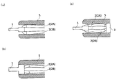
- FIG. 4A at least one of the first wire portion 2A and the second wire portion 2B is in contact with the inner wall of the sheath 5, so that the position of the distal tip 1 can be fixed. Further, as shown in FIG.
- the tip 1 has an opening 11 as an insertion passage through which the wire 2 is inserted, and an inlet and an outlet of the insertion passage are provided on the proximal end surface of the tip 1. Good. Thereby, it can be set as the aspect by which a part of wire 2 is arrange
- the distal tip 1 Since the distal tip 1 has such an embodiment and the outer diameter of the distal tip 1 is larger than the inner diameter of the sheath 5, the distal tip 1 comes into contact with the inner wall of the sheath 5 as shown in FIG. The tip 1 can be fixed. Further, as shown in FIG.
- the position of the tip 1 is fixed because the connecting tool contacts the inner wall of the sheath by making the outer diameter of the connecting tool 3 larger than the inner diameter of the sheath 5. Can do. By combining these modes, a plurality of locations may contact the inner wall of the sheath.
- the wire may be provided with a bent portion.
- the bent portion is formed, for example, by bending a wire or joining two or more wires at an angle. Only one bent portion may be provided, or a plurality of bent portions may be provided.
- the bending part may be formed in the shape of a broken line, and may be formed in the shape of a curve.
- the wire has a first bent portion in the first wire portion and a second bent portion in the second wire portion.
- the degree of freedom in designing the shape of the snare of the treatment instrument can be increased, and the distal tip can be reliably projected and more stably fixed to the sheath distal end.
- the first bent portion 21 and the second bent portion 22 are provided on the distal side of the center of the wire 2 in the perspective direction.
- the first bent portion and the second bent portion are preferably in contact with the inner wall of the sheath. Thereby, a wire can be more stably fixed with a sheath.
- the first bent portion and the second bent portion are preferably formed so as to be convex inward in the radial direction of the sheath.
- the wire tends to extend radially outward in the first wire portion on the proximal side of the first bent portion and in the second wire portion on the proximal side of the second bent portion.
- the diameter of the snare in the direction perpendicular to the perspective direction of the sheath can be increased.
- the convexity of the bent part toward the radially inner side of the sheath means that the convex part of the bent part is arranged toward the inside of the sheath.
- the fact that the wire is convex outward in the radial direction of the sheath means that the wire has a loop shape that bulges outward and spreads.
- the position where the first bent portion and the second bent portion are provided can be appropriately set according to the shape of the snare, but at least one of the first bent portion and the second bent portion is
- the wire is provided at the distal end portion, and more preferably, the first bent portion and the second bent portion are both provided at the distal end portion.
- the diameter of a snare can be enlarged in the comparatively wide range of the perspective direction of a sheath.
- the first bent portion and the second bent portion may be arranged facing each other. Thereby, when the wire is accommodated in the sheath, twisting of the wire can be reduced, and an unnecessary load is not applied to fixing the tip. Further, the first bent portion and the second bent portion may be formed symmetrically with respect to a line extending in the perspective direction of the sheath, or may be formed asymmetrically. Furthermore, the 1st bending part and the 2nd bending part may be arrange
- the first bent portion and the second bent portion are provided close to each other.
- the first bent portion to the second bent portion are constituted by one wire and the tip is disposed between the first bent portion and the second bent portion, the wire extending direction (the long axis of the wire) In the direction)
- the length from the first bent portion to the second bent portion is preferably 1 to 3 times the length of the tip. This hardly affects the shape of the other part of the snare and increases the degree of freedom in designing the shape of the snare.
- the first bent portion and the second bent portion may be formed before the wire and the tip end are connected, or may be formed after the wire and the tip end are connected.
- the wire is a first wire portion and a third bent portion closer to the proximal side than the first bent portion, and a second wire portion and a fourth bent portion closer to the proximal side than the second bent portion. You may have. Furthermore, by providing the third bent portion and the fourth bent portion, twisting of the wire can be reduced when the wire is accommodated in the sheath. Further, the pressing force applied to the sheath from the wire resulting from the deformation of the wire caused by being housed in the sheath can be controlled so that the contact between the sheath and the wire is not adversely affected.
- the position where the third bent portion and the fourth bent portion are provided can be appropriately set according to the shape of the snare, but the third bent portion and the fourth bent portion face each other. It is preferable that they are arranged. Thereby, when the wire is accommodated in the sheath, twisting of the wire can be reduced, and an unnecessary load is not applied to fixing the tip.
- the 3rd bending part and the 4th bending part may be formed in line symmetry with respect to the line extended in the perspective direction of a sheath, and may be formed asymmetrically.
- the 3rd bending part and the 4th bending part may be arrange
- the third bent portion 23 and the fourth bent portion 24 may be provided closer to the proximal side than the center of the wire 2 in the perspective direction. Thereby, the diameter of the snare in the direction perpendicular to the perspective direction of the sheath can be increased at the center of the wire 2 in the perspective direction.
- the third bent portion and the fourth bent portion are preferably formed so as to be convex inward in the radial direction of the sheath.
- the wire tends to extend outward in the radial direction on the distal side of the third bent portion and on the second wire portion on the distal side of the fourth bent portion. Therefore, the diameter of the snare in the direction perpendicular to the perspective direction of the sheath can be increased.
- the bent portions may be in contact with each other like the third bent portion 23 and the fourth bent portion 24 shown in FIG. 2, and the bent portions like the first bent portion 21 and the second bent portion 22 shown in FIG. They may be arranged apart from each other.
- the first bent portion, the second bent portion, the third bent portion, and the fourth bent portion of the wire are preferably formed in substantially the same plane. This is because the shape of the wire can be made simpler and the twist of the wire can be reduced.
- the distance between the first bent portion and the second bent portion in the same plane may be greater than the distance between the third bent portion and the fourth bent portion.
- the third bent portion and the fourth bent portion may be formed before fixing the wire and the connection tool, or may be formed after fixing the wire and the connection tool.
- the wire has one or more bent portions (hereinafter referred to as a fifth bent portion) at the distal end portion.
- the fifth bent portion may be provided distal to the first bent portion and distal to the second bent portion. That is, it is preferable that the fifth bent portion is provided between the first bent portion and the second bent portion.
- the fifth bent portion is preferably formed to be convex toward the distal side.
- the fifth bent portions are preferably formed so as to be convex outward in the radial direction of the sheath.
- the fifth bent portion may be disposed in the opening.
- the tip is disposed at the most distal end of the snare, and the tip is projected from the sheath and is easily fixed.
- the position of the tip tip with respect to the wire can be made constant by arranging the tip tip at the most distal end of the wire and arranging the first bent portion and the second bent portion at both ends of the opening.
- the plurality of fifth bent portions may be formed line-symmetrically or asymmetrically with respect to a line extending in the perspective direction of the sheath. Further, the plurality of fifth bent portions may be disposed at the same position in the perspective direction of the sheath or may be disposed at different positions.
- the proximal side of the wire and the sheath are connected to the operation handle.
- the operation handle performs protrusion, retraction, and rotation of the wire from the sheath.
- the handle preferably has a first fixing part to which the sheath is fixed and a second fixing part to which the linear object is fixed.
- the force that the tip of the tip fixed to the sheath tip receives from the living body by the incision is smaller than the force required for the advancement / retraction operation of the tip by the handle operation, so the tip of the tip is not fixed to the sheath tip at the time of incision never do.
- the handle is connected to a high frequency power source and supplies power to the wire and the tip through a linear object.
- ⁇ / RTI> By inserting the treatment instrument of the present invention through the treatment instrument insertion channel of the endoscope, it can be introduced into the body and used. In order not to damage the treatment instrument insertion channel and other than the lesioned part in the body, it is desirable that the tip and the wire are accommodated in the sheath even when the power is not supplied.
- a part of the tip, at least one of the first wire part and the second wire part, or one or more of the connecting tools are in contact with the inner wall of the sheath, and the tip is used as a high-frequency knife for treatment.
- the tip tip, the first wire portion, the second wire portion, or the connection tool is fixed to the sheath, so that a normal handle can be used unless an excessive force is applied to the tip tip. Operations such as incision and marking with a knife can be performed.
- the wire is protruded from the sheath tip by operating the handle.
- the pressing force for operating the handle decreases.
- the connecting tool is made smaller than the inner diameter of the sheath, the wire can be smoothly projected after at least one of the tip, first wire portion, and second wire portion protrudes from the sheath.
- the location where the force for fixing the wire to the sheath acts is at least one of the tip tip and the first wire portion and the second wire portion, in order to fix the tip tip to the sheath after these protrude.
- the power of is hard to work.
- Example 1 As the treatment instrument of Example 1, the treatment instrument shown in FIGS.
- the treatment instrument As the tip 1, a stainless steel cylinder having a height (length in the left-right direction in FIG. 2) of 2.2 mm, a proximal diameter of 1.9 mm, and a distal diameter of 0.4 mm.
- a through hole 11 having a diameter of 0.5 mm was provided on the proximal side of the tip 1.
- the wire 2 a wire in which seven stainless steel wires having a length of 110 mm and a diameter of 0.1 mm were twisted together was used.
- As the wire 4 one in which five stainless steel wires having a diameter of 0.5 mm were twisted together was used.
- the wire 2 was connected to the through hole 11 of the tip 1.
- the wire 2 was inserted into both ends of the wire 2 from one end of a stainless steel pipe as a connection tool 3, and the pipe was caulked to fix the wire 2 to the pipe in a loop shape.
- the outer diameter of the pipe was 1.9 mm.
- the pipe was placed on the proximal side, and the tip tip 1 was placed at the most distal end of the wire 2.
- the tip tip 1 and the wire 2 are pinched so that the loop area is increased.
- the first wire portion 2A and the second wire portion 2B of the wire 2 are 5.0 mm proximal from the distal end 20 of the wire 2.
- the wire 2 was bent so that a portion proximal to the base point extended outward in the radial direction of the sheath.
- the first bent portion 21 was formed on the first wire portion 2A
- the second bent portion 22 was formed on the second wire portion 2B.
- the first bent portion 21 and the second bent portion 22 are arranged to face each other in the open state of the loop.
- the distal side of the base point is set so as to increase the loop area.
- the wire 2 was bent so that the portion extended outward in the radial direction of the sheath 5. Thereby, the 3rd bending part 23 was formed in the 1st wire part 2A, and the 4th bending part 24 was formed in the 2nd wire part 2B. Thereafter, the wire 4 was inserted from the other end of the pipe, the pipe was caulked, and the wire 2 was fixed to the distal side of the wire 4 via the pipe.
- the sheath 5 As the sheath 5, a tube made of polytetrafluoroethylene having an outer diameter of 2.5 mm and an inner diameter of 1.8 mm was used.
- the linear object 4 was inserted from the distal side of the sheath 5, and the linear object 4 and the sheath 5 were each fixed to the handle 6.
- the tip 1 and the wire 2 could be inserted and removed from the sheath tip.
- the treatment tool was introduced into the body through an endoscope, and only the distal tip 1 protruded from the sheath, so that the lesioned part could be stably incised.
- the lesion part partially incised with a knife could be excised by squeezing with a wire protruding entirely from the sheath, and cauterized.
Landscapes
- Health & Medical Sciences (AREA)
- Surgery (AREA)
- Engineering & Computer Science (AREA)
- Life Sciences & Earth Sciences (AREA)
- Biomedical Technology (AREA)
- Otolaryngology (AREA)
- Nuclear Medicine, Radiotherapy & Molecular Imaging (AREA)
- Plasma & Fusion (AREA)
- Physics & Mathematics (AREA)
- Heart & Thoracic Surgery (AREA)
- Medical Informatics (AREA)
- Molecular Biology (AREA)
- Animal Behavior & Ethology (AREA)
- General Health & Medical Sciences (AREA)
- Public Health (AREA)
- Veterinary Medicine (AREA)
- Surgical Instruments (AREA)
Abstract
本発明の内視鏡用高周波処置具は;シース(5)と;シース(5)内に配置されている線状物(4)と;シース(5)の遠近方向にそれぞれ延在している第1ワイヤ部(2A)および第2ワイヤ部(2B)とを有しており、第1ワイヤ部(2A)の近位端部と第2ワイヤ部(2B)の近位端部が線状物(4)に固定されている導電性ワイヤ(2)と;第1ワイヤ部(2A)の遠位端部と、第2ワイヤ部(2B)の遠位端部にそれぞれ連結されている導電性先端チップ(1)と;線状物(4)と第1ワイヤ部(2A)と第2ワイヤ部(2B)をつなぐ導電性接続具(3)と;を備え;導電性先端チップ(1)の一部がシース(5)から突出した状態で、導電性接続具(3)、第1ワイヤ部(2A)、第2ワイヤ部(2B)、導電性先端チップ(1)の少なくともいずれか1つが、シース(5)の内壁と接している。
Description
本発明は、内視鏡を経由して生体内に導入される高周波処置具に関するものである。より詳しくは、内視鏡用高周波処置具であって、ワイヤ状の切断部を備えるものに関する。
従来、人体内に挿入し、先端に対物レンズや照明レンズを備え、体腔内を観察しつつ、手元側から先端側に通じる処置具挿通チャンネルを経由して体腔内で処置を行う処置具を導入する内視鏡がある。このような内視鏡を用いた処置として内視鏡的粘膜下層剥離術(Endoscopic Submucosal Dissection:ESD)や、内視鏡的粘膜切除術(Endoscopic Mucosal Resection:EMR)が知られている。
内視鏡を通じて用いる処置具には、ナイフやスネアがある。ナイフは、体腔表面を切開するためのものである。細かい切除作業を行うためには、ナイフはシースに安定的に固定されており、手元側の操作部による操作を先端側に確実に伝達する必要がある。スネアは、ループ状のワイヤを備え、体腔表面の隆起部をループで囲い、ループ径を小さくして隆起部の根元を絞り、切除するためのものである。スネアのループワイヤは、病変部の根元部分を引き絞って絞扼するため、ループワイヤがシースから出し入れ可能であり、ループワイヤは弾性変形可能なワイヤで構成される必要がある。いずれの処置具も、手元側から電力を供給し、電流を発生させて体腔表面を切除、焼灼等する高周波処置具として用いられる。
内視鏡を通じて用いるナイフとして、特許文献1に開示される高周波処置具がある。このナイフは、シースと、シース内部から突出可能に設けられ先端に高周波電流が印加される針状の電極を備える。このナイフは、針状電極からなるナイフの突出量を規制し、切開の処置が行われるナイフの部位の安定性を確保するために、シース内にナイフの外径より大きい孔径を有する硬質筒体を設け、ナイフの手元側の箇所に複数のストッパ突起を設けている。硬質筒体と、ストッパ突起とが面接触することにより、シースの先端面からのナイフの突出長を規制し、ナイフをシースの長軸中心上に安定的に保持できる。
内視鏡を通じて用いるスネアとして、特許文献2に開示される高周波スネアがある。このスネアは、シースと、シース内に進退可能に挿通配置された導電性のループワイヤを備える。このスネアは、病変部の根元部分を高周波電流で中心部分まで出血なく確実に焼灼絞断するために、シース先端に先端電極を設けている。また、このスネアは、ループワイヤ先端の曲げ戻し部分への応力集中の程度を小さくするために、ループワイヤの先端に先端チップを通している。
ナイフはESDに用いられる。ESDは、経内視鏡的に消化器の病変部を徐々に剥離させていく手技で病変部を細かに切除できる利点がある。一方で、処置に時間がかかり、術者の技術も要求される。スネアはEMRに用いられる。EMRは、経内視鏡的に病変部をループで囲い、引き絞ることで切除する手技で広範囲を容易に切除できる。しかし、狙った箇所のみを正確に切除することが困難であり、使用できる病変部の形状も限られる。
そこで、まずナイフを用いて狙った病変部の周りを切開して少量剥離させ、一旦ナイフを内視鏡から引き抜いた後、スネアに交換し、ナイフで剥離した箇所にスネアのループを当て、病変部を引き絞ることで病変部の切除の精度を維持しつつ、手技の時間の短縮を図る手法が検討されている。
このような手技に用いるための処置具として、スネアのループワイヤの先端に尖頭部を設けたものが提案されている。特許文献3では、シースと、シース内に引き込まれた際には弾性変形して窄まるスネアループを備える内視鏡用高周波スネアが開示されている。このスネアは、このスネアループの先端部分に、ワイヤの先端部分が貫通する状態に電気絶縁性の先端チップを固定的に取り付けて、ワイヤを先端チップから前方へ突出させ、その突出部分を棒状先端電極とする。このスネアの棒状先端電極はナイフとして用いることができる。切開用ナイフとして用いる場合には、スネアループを先端部分を残してシース内に引き込み、先端部分のみをシースから突出させる。
ナイフを用いてESDを行う場合には、病変部を細かく切除するために、手技中にナイフ先端がぶれない構造であることが必要である。また、手元の操作部の動きを確実に先端の操作部に伝えるためには、先端部が安定的に固定されていることが必要である。一方で、処置具を病変部まで搬送する間に不用意に内視鏡の処置具挿通チャンネル内や、体腔内を傷つけないように、処置時以外は通電、非通電に関わらず処置部はシース内に保持され、処置時にシース先端から突出可能であることが望ましい。
また、スネアの先端にナイフ部を設けた処置具をナイフとして使用する場合には、ナイフの手元側は弾性変形可能なワイヤで構成させるスネアであること、ナイフ部で切開後にスネアループを展開し、病変部を絞扼することを考慮して、ナイフ部がシースに固定される必要がある。
特許文献1に示される高周波ナイフでは、ナイフをシース先端に固定するために、シースに硬質筒体を設け、ナイフにストッパ突起を設けている。硬質筒体とストッパとの面接触により、ナイフが固定される。このような構成とした場合、処置具の部品点数が増えることとなる。また、ナイフは硬質筒体とストッパとの面接触により完全に固定されるため、シース先端面から所定長突出した後は、それ以上ナイフを突出させることはできない。
特許文献2に示される高周波スネアは、先端電極をナイフとして使用することが予定されていないため、先端電極の固定機構について開示がない。
特許文献3に示される内視鏡用高周波スネアでは、先端ナイフ部は、先端チップとシース先端との接触により固定される。電気絶縁性の先端チップは、シース先端面より先端側のスネアループに設けられている。このため、先端ナイフ部を用いて体腔内で処置を行う場合には、シース先端面と先端チップとが接触するためナイフ部がシース内部に引き込まれることがなく、ナイフ位置を安定させることができる。しかし、本処置具を内視鏡の処置具挿通チャンネルに挿通する際や、体腔内の非処置部に処置具が位置する場合には、ナイフ部が常にシースから露出しているため、非通電時であっても周囲を傷つける恐れがある。
そこで本発明は、これらの課題に鑑みてなされたものであり、スネアの先端部にナイフ部を設けた処置具において、ナイフ部を安定的に固定することができる内視鏡用高周波処置具を提供することを目的とする。
本発明の内視鏡用高周波処置具は、前記課題を解決するために以下の構成を備える。本発明の内視鏡用高周波処置具は、シースと;該シース内に配置されている線状物と;シースの遠近方向にそれぞれ延在している第1ワイヤ部および第2ワイヤ部とを有しており、第1ワイヤ部の近位端部と第2ワイヤ部の近位端部が線状物に固定されている導電性ワイヤと;第1ワイヤ部の遠位端部と、第2ワイヤ部の遠位端部にそれぞれ連結されている導電性先端チップと;線状物と第1ワイヤ部と第2ワイヤ部をつなぐ導電性接続具と;を備え;導電性先端チップの一部がシースから突出した状態で、導電性接続具、第1ワイヤ部、第2ワイヤ部および導電性先端チップの少なくともいずれか1つが、シースの内壁と接していることを特徴とする。このように、シース内に配置される部品がシースの内壁と接する構成とすることで、導電性先端チップをシース先端に安定的に固定し、導電性先端チップのみをシースから突出させることができる。
本発明によれば、スネア先端にナイフ部としての導電性先端チップが設けられた内視鏡用高周波処置具の導電性先端チップがシース先端に安定的に固定されるため、処置具をナイフとして用いる際には導電性先端チップのみをシースから突出させることができる。
本発明の内視鏡用高周波処置具は、内視鏡の処置具挿通チャンネルに挿通され、体腔内のマーキング、切開、絞扼などの処置や、ESD、EMRなどの術式に用いられるものである。高周波処置具は、遠位側にナイフ部とスネア部とを有する。高周波処置具をナイフとして用いる際には、先端のナイフ部のみをシース先端から安定的に突出させることができ、スネアとして用いる際には、スネア部として例えばループ状に形成された導電性ワイヤをシースから突出させることができる。以下では、内視鏡用高周波処置具を単に「処置具」と称することがある。
図1~図4に示すように、本発明の内視鏡用高周波処置具は;シースと;該シース内に配置されている線状物と;シースの遠近方向にそれぞれ延在している第1ワイヤ部および第2ワイヤ部とを有しており、第1ワイヤ部の近位端部と第2ワイヤ部の近位端部が線状物に固定されている導電性ワイヤと;第1ワイヤ部の遠位端部と、第2ワイヤ部の遠位端部にそれぞれ連結されている導電性先端チップと;線状物と第1ワイヤ部と第2ワイヤ部をつなぐ導電性接続具と;を備える。導電性先端チップの一部がシースから突出した状態で、導電性接続具、第1ワイヤ部、第2ワイヤ部および導電性先端チップの少なくともいずれか1つが、シースの内壁と接している。このように、シース内に配置される部品が、シースの内壁と接する構成とすることで、導電性先端チップをシース先端に安定的に固定し、導電性先端チップのみをシースから突出させることができる。なお、遠位側とは内視鏡の体腔内に挿入される先端側であり、近位側とは遠位側と反対側であって、内視鏡や処置具の操作を行う手元側をいう。また、「長さ」とは特記しない場合はシースの遠近方向(シースの長軸方向)における長さを指す。以下では「導電性接続具」を「接続具」、「導電性ワイヤ」を「ワイヤ」、「導電性先端チップ」を「先端チップ」と称することがある。第1ワイヤ部および第2ワイヤ部の近位端部は、例えば近位端を含み、近位端から30mm以内の部分であることが好ましく、より好ましくは20mm以内の部分である。また、第1ワイヤ部および第2ワイヤ部の遠位端部は、例えば遠位端を含み、遠位端から30mm以内の部分であることが好ましく、より好ましくは20mm以内の部分である。
本発明の内視鏡用高周波処置具のシースは、内部に線状物やワイヤを収納可能な長尺の中空部材である。シースの内表面は、シース内部に収納される接続具、ワイヤ、先端チップの少なくともいずれか1つ、または全部と接触し、接続具、ワイヤまたは先端チップを固定できる程度の表面性と強度を有する。さらに、シースは、内視鏡の処置具挿通チャンネル内を挿通可能な外表面の滑り性と、処置具挿通チャンネル内腔の形状に沿って屈曲する可撓性と、処置対象組織まで確実に到達する剛性をバランス良く兼ね備えていることが望ましい。
シースとしては、例えば、金属や合成樹脂から構成されたコイル体、短筒状の関節駒を長軸方向に複数連結して回動可能にした筒体、合成樹脂から構成された筒体、またはこれらの組み合わせが用いられる。シースを構成する合成樹脂としては、例えば、ナイロン等のポリアミド樹脂、ポリプロピレン(PP)、ポリエチレン(PE)等のポリオレフィン樹脂、ポリエチレンテレフタレート(PET)等のポリエステル樹脂、ポリエーテルエーテルケトン(PEEK)等の芳香族ポリエーテルケトン樹脂、ポリイミド樹脂、ポリテトラフルオロエチレン(PTFE)、テトラフルオロエチレン-パーフルオロアルキルビニルエーテル共重合体(PFA)、エチレン-テトラフルオロエチレン共重合体(ETFE)等のフッ素樹脂等を用いることができる。
シースの長さは、併用する内視鏡の長さに従って適宜設定することができるが、一般的には1650mmから2300mmであることが多い。シースの外径は、1.8mmから3.5mm、シースの内径は1.2mmから3.0mmであることが好ましい。シースの可撓性や剛性は、シースの材料だけでなく厚さによっても制御することができる。シースの厚さは用いる材料によって選択できるが、シースがフッ素樹脂から構成される場合は0.2mm以上であることが好ましい。シースの外径および内径は、一定であってもよく、シースにテーパ部を設けることで複数の箇所で径が変化していてもよい。
シースの遠近方向に垂直な方向の接続具の径(外径)と、シースの遠近方向に垂直な方向の先端チップの径(外径)の少なくともいずれか一方が、シースの内径以上の大きさであることが好ましく、シースの内径より大きいことがより好ましい。先端チップの一部が前記シースから突出したときに、接続具と先端チップの少なくともいずれか一方が、シース内径を広げるように接触することで、先端チップをシース先端に更に安定的に固定し、先端チップのみをシースから突出させることができる。
接続具の径とシースの内径との差や、先端チップの径とシースの内径との差は0.5mm以内であることが好ましい。接続具の径と先端チップの径は同じでもよく、異なっていてもよい。
線状物は、シース内に配置されている長尺物である。線状物は、操作部とワイヤとを接続して、ワイヤをシース内外に移動させたり、操作部側の回転操作をワイヤ側に伝えるために用いられる。ワイヤの移動に伴い、線状物がシース外に移動してもよい。なお、線状物の長さは、内視鏡の処置具挿通チャンネルより長いことが必要である。
シース内に収納される線状物は、弾性変形可能な材料から構成されることが好ましい。線状物の弾性は、内視鏡の処置具挿通チャンネルの変形に追随するシースに沿って形状が変化する程度の弾性であれば足りる。線状物を構成する材料としては、弾性変形可能な材料であれば特に限定されないが、Ni-Ti系合金などの超弾性合金や、SUS303、SUS304などのステンレスなどの金属、ナイロンなどのポリアミド系樹脂などの樹脂、またはこれらの組み合わせを用いることができる。
線状物は、1の部材で形成されていてもよく、複数の部材が線状物の長軸方向の途中で接合されて形成されていてもよい。線状物の長軸方向の途中で複数の線材を接合する場合は、線材間を通常の接合方法で接合すればよい。接合方法は、例えば、金属管でかしめて結合する、溶接、溶着や接着するなどの方法がある。
線状物は、単線であっても、単線をより合わせた撚線であってもよい。単線であれば、製造が容易である。撚線であれば、線状物の強度を上げることができるので、操作部側の回転などの操作をより確実に先端部に伝えることができる。
ワイヤは、遠近方向に延在している長尺物であり、少なくともその一部をシースの遠位側から露出させることによって処置具のスネアとして用いられる。ワイヤは、シースの遠近方向にそれぞれ延在している第1ワイヤ部および第2ワイヤ部とを有しており、第1ワイヤ部の近位端部と第2ワイヤ部の近位端部が線状物に固定されている。
第1ワイヤ部の少なくとも1箇所がシースの内壁と接しており、第2ワイヤ部の少なくとも1箇所がシースの内壁と接していることが好ましい。これにより、先端チップがシース先端により安定的に固定される。なお、第1ワイヤ部または第2ワイヤ部のいずれか一方の少なくとも2箇所が、シースの内壁と接していることにより、先端チップをシースの先端により安定的に固定することもできる。
第1ワイヤ部と第2ワイヤ部が、シースの遠近方向に延びる線に対して線対称に形成されていてもよく、非対称に形成されていてもよい。
ワイヤは、遠位端部において第1ワイヤ部と第2ワイヤ部が一体形成されていることが好ましい。これにより、ワイヤの構成を簡素化することができる。また、ワイヤは、第1ワイヤ部と第2ワイヤ部が別部材であってもよい。これにより、第1ワイヤ部と第2ワイヤ部を構成する材料を異ならせてスネアの形状を複雑にするなど、スネアの設計の自由度を増すことができる。
線状物に固定されるワイヤは、導電性があり、弾性変形可能な材料から構成されることが好ましい。ワイヤの弾性は、シース先端から突出した後のスネアの形状、例えばループ状の形状に復元する程度である必要がある。また、適宜屈曲部を設けるため、ワイヤは曲げ加工が容易である材料から構成されていることが好ましい。ワイヤの材料としては、Ni-Ti系合金などの超弾性合金や、SUS303、SUS304などのステンレスなどの金属を用いることが好ましい。
ワイヤの長さや直径は、スネアの用途に応じて適宜選択することができる。ワイヤの長さは、60mmから200mmであることが好ましい。そのうち、線状物との接続部の長さは、2mmから10mmであることが好ましい。ワイヤの直径は、0.2mmから1.0mmであることが好ましい。
線状物とワイヤは、通常の接合方法で接続することができ、直接接続しても別の部材を介して接続してもよい。接合方法としては、例えば、金属管でかしめて結合する、溶接、溶着や接着するなどの方法がある。弾性変形可能な金属製のワイヤの両端を線状物に接続する場合は、金属管を介して接続することが好ましい。
接続具は、前述の線状物とワイヤとの接続に用いた接続部とすることができる。接続具は、接続に用いた接続部材でもよく、ワイヤの近位端側の接続部付近に設けられた導電性部材であってもよい。接続具は、SUS303、SUS304などのステンレスなどの金属材料から構成されることが好ましい。接続具の形状は、円状、楕円状、柱状、錐状やこれらを組み合わせた形状としたり、一部が屈曲している形状や拡幅している形状などにすることができる。シースの遠近方向における接続具の長さは2.0~10.0mmであることが好ましい。
ワイヤの形状は、ループ状が好ましく、中でも両端が線状物の遠位端に固定されたループ状がより好ましい。ループ状は、例えば、ナイフ部を含むスネア部が閉じた環状であることをいい、円形状、楕円形状、多角形状などとすることができる。ワイヤの途中を折ったり、曲げたりするなどして、後述する屈曲部を設けることにより形状を変化させることができる。ワイヤの一部は、好ましくはシースに接するため、ワイヤに連結された先端チップをシースの先端から突出するように固定することができる。
ワイヤの遠位端側であって第1ワイヤ部と第2ワイヤ部の一箇所ずつが、シースに接していることが好ましい。先端チップをシースから突出させるときに、より強固にワイヤをシースに固定できるためである。ワイヤの近位側や遠位側と近位側の間の部分で、複数箇所がシースに接してもよい。ループ状のワイヤは、シース内径よりも大きいループ径を有するため、ワイヤをシース内で収納すると、ループがたたまれてワイヤの複数箇所がシースに接することとなる。
先端チップは、高周波ナイフとして用いられる部分である。先端チップは、第1ワイヤ部の遠位端部と、第2ワイヤ部の遠位端部にそれぞれ連結されている。先端チップは、導電性の材料から構成される。先端チップは、SUS303、SUS304などのステンレスなどの金属材料から構成されることが好ましい。先端チップの形状はナイフの用途に合わせて適宜選択することができ、例えば、球状、楕円球状、柱状、錐状やこれらを組み合わせた形状としたり、先端側を屈曲させたり拡幅したりすることができる。先端チップのシース遠近方向の長さは、処置具の用途やシース先端面からの突出長さに応じて適宜選択することができるが、2.0mmから5.0mmであることが好ましい。先端チップは処置具の最遠位に配置される。
ワイヤと先端チップは、通常の連結方法で連結することができ、直接接続しても別の部材を介して接続してもよく、例えば、金属管でかしめて結合する、溶接、溶着や接着するなどの方法がある。中でも、先端チップが開口部を有し、該開口部内にワイヤの一部が位置することにより先端チップとワイヤが連結されていることが好ましい。これにより、先端チップとワイヤが効率よく連結される。より好ましくは、先端チップの近位側に開口部が設けられ、該開口部内にワイヤの一部が位置することにより先端チップとワイヤが連結される。このように、先端チップに開口部が設けられて、該開口部にワイヤを挿通することでワイヤと先端チップを連結する方法は、ワイヤの遠位端部において第1ワイヤ部と第2ワイヤ部が一体形成されている場合に好適に使用できる。開口部は、先端チップに貫通孔やくぼみを設けるなどして形成することができる。先端チップはワイヤに対して回転可能であってもよく、ワイヤの長軸方向に沿って移動可能でもよく、完全に固定されていてもよい。ワイヤの長軸方向とは、ワイヤの延在方向に沿った方向をいう。先端チップがワイヤの長軸方向に沿って移動可能とは、ワイヤが両端を線状物に固定された円形状である場合、先端チップがその円の周方向に沿って移動可能であることをいう。また、ワイヤの第1ワイヤ部と第2ワイヤ部が別部材である場合、ワイヤと先端チップは、溶接、溶着、接着によって連結されていることが好ましい。
先端チップの開口部の深さ方向が、シースの遠近方向と異なる方向であることが好ましく、シースの遠近方向と垂直な方向であることがより好ましい。これにより、ワイヤよりも遠位側に先端チップの遠位端を配置することができる。図2に示すように、先端チップ1には、シースの遠近方向と垂直な方向に向かって貫通している開口部11を設けることができる。これにより、図4(a)に示すように、第1ワイヤ部2Aおよび第2ワイヤ部2Bの少なくともいずれか一方がシース5の内壁に接するため、先端チップ1の位置を固定することができる。また、図3に示すように、先端チップ1はワイヤ2が挿通される挿通路としての開口部11を有し、挿通路の入口と出口が先端チップ1の近位端面に設けられていてもよい。これにより、ワイヤ2の一部がシース5の遠近方向と垂直な方向に配置される態様とすることができる。先端チップ1をこのような態様とし、先端チップ1の外径をシース5の内径以上の大きさにすることで、図4(b)に示すように先端チップ1がシース5の内壁に接するため、先端チップ1を固定することができる。また、図4(c)に示すように、接続具3の外径をシース5の内径以上の大きさにすることで接続具がシースの内壁に接するため、先端チップ1の位置を固定することができる。これらの態様を組み合わせて、複数箇所がシースの内壁に接するようにしてもよい。
スネアとして用いるワイヤと、ナイフとして用いる先端チップをともに導電性とすることで、本発明の処置具をスネアとして用いる際に、ワイヤの遠位側に非導電性の箇所がなく効率的に絞扼、焼灼を行うことができる。
ワイヤには屈曲部が設けられていてもよい。これにより、病変部の大きさや形状、手技の種類に応じてスネアの形状を適切に設計することができるとともに、先端チップを確実に突出させ、かつシース先端に一層安定して固定することができる。屈曲部は、例えば、ワイヤを折り曲げたり、2つ以上のワイヤを、角度を付けて接合することで形成される。屈曲部は、1つのみ設けられていてもよく、複数設けられていてもよい。また、屈曲部は、折れ線状に形成されていてもよく、曲線状に形成されていてもよい。
ワイヤは、第1ワイヤ部に第1屈曲部を有し、第2ワイヤ部に第2屈曲部を有していることが好ましい。このようにワイヤに屈曲部を設けることにより、処置具のスネアの形状設計の自由度が増すとともに、先端チップを確実に突出させ、かつシース先端に一層安定して固定することができる。図2では、第1屈曲部21と第2屈曲部22は、ワイヤ2の遠近方向の中心よりも遠位側に設けられている。
ワイヤがシース内に収容されている場合、第1屈曲部と第2屈曲部が、シースの内壁と接していることが好ましい。これによりワイヤをシースでより安定的に固定することができる。
ワイヤがシース外に露出するときに、第1屈曲部と第2屈曲部は、シースの径方向内方に向かって凸となるように形成されていることが好ましい。これにより、第1ワイヤ部では、第1屈曲部よりも近位側、第2ワイヤ部では第2屈曲部よりも近位側において、ワイヤがそれぞれ径方向の外方側に延在しやすくなり、シースの遠近方向に垂直な方向におけるスネアの径を大きくすることができる。なお、屈曲部がシースの径方向内方に向かって凸とは、シースの内側に向かって屈曲部の凸部が配置されていることをいう。ワイヤがシースの径方向外方に向かって凸とは、ワイヤが外側に膨らんで広がったループ状であることをいう。
シースの遠近方向において、第1屈曲部と第2屈曲部が設けられる位置は、スネアの形状にあわせて適宜設定することができるが、第1屈曲部と第2屈曲部の少なくともいずれか一方が、ワイヤの遠位端部に設けられていることが好ましく、第1屈曲部と第2屈曲部がいずれも遠位端部に設けられていることがより好ましい。これにより、シースの遠近方向の比較的広い範囲でスネアの径を大きくすることができる。
第1屈曲部と第2屈曲部は互いに面して配置されていてもよい。これにより、ワイヤをシース内に収納する時に、ワイヤのねじれを低減でき、先端チップの固定に不要な負荷がかかることがない。また、第1屈曲部と第2屈曲部は、シースの遠近方向に延びる線に対して線対称に形成されていてもよく、非対称に形成されていてもよい。さらに、第1屈曲部と第2屈曲部は、シースの遠近方向の同じ位置に配置されていてもよく、異なる位置に配置されていてもよい。
また、第1屈曲部と第2屈曲部は近接して設けられていることが好ましい。第1屈曲部から第2屈曲部までが1本のワイヤで構成され、第1屈曲部と第2屈曲部の間に先端チップが配置されている場合、ワイヤの延在方向(ワイヤの長軸方向)において、第1屈曲部から第2屈曲部までの長さは、先端チップの長さの1倍以上3倍以下であることが好ましい。これにより、スネアの他の部分の形状に影響を与えることが少なく、スネアの形状設計の自由度も増す。
第1屈曲部と第2屈曲部は、ワイヤと先端チップを連結する前に形成してもよく、ワイヤと先端チップを連結した後で形成してもよい。
さらに、ワイヤは、第1ワイヤ部であって第1屈曲部よりも近位側に第3屈曲部と、第2ワイヤ部であって第2屈曲部よりも近位側に第4屈曲部とを有していてもよい。さらに第3屈曲部および第4屈曲部を設けることにより、ワイヤをシース内に収納する際にワイヤのねじれを低減することができる。また、シース内に収納されることにより生じるワイヤの変形から生じるワイヤからシースに対する押圧力を制御し、シースとワイヤとの接触に悪影響を及ぼさないようにすることができる。シースの遠近方向において、第3屈曲部と第4屈曲部が設けられる位置は、スネアの形状にあわせて適宜設定することができるが、第3屈曲部と第4屈曲部は、互いに面して配置されていることが好ましい。これにより、ワイヤをシース内に収納する時に、ワイヤのねじれを低減でき、先端チップの固定に不要な負荷がかかることがない。また、第3屈曲部と第4屈曲部は、シースの遠近方向に延びる線に対して線対称に形成されていてもよく、非対称に形成されていてもよい。また、第3屈曲部と第4屈曲部は、シースの遠近方向の同じ位置に配置されていてもよく、異なる位置に配置されていてもよい。
図2に示すように、第3屈曲部23と第4屈曲部24は、ワイヤ2の遠近方向の中心よりも近位側に設けられていてもよい。これにより、ワイヤ2の遠近方向の中心において、シースの遠近方向と垂直な方向のスネアの径を大きくすることができる。
ワイヤがシース外に露出するときに、第3屈曲部と第4屈曲部は、シースの径方向内方に向かって凸となるように形成されていることが好ましい。これにより、第1ワイヤ部では、第3屈曲部よりも遠位側、第2ワイヤ部では第4屈曲部よりも遠位側において、ワイヤがそれぞれ径方向の外方側に延在しやすくなるため、シースの遠近方向と垂直な方向におけるスネアの径を大きくすることができる。
図2に示す第3屈曲部23と第4屈曲部24のように、屈曲部同士が接していてもよく、図2に示す第1屈曲部21と第2屈曲部22のように、屈曲部同士は離れて配置されていてもよい。ワイヤの第1屈曲部、第2屈曲部、第3屈曲部、第4屈曲部は、略同一平面状に形成されることが好ましい。ワイヤの形状をより単純にすることができ、ワイヤのねじれを低減することができるからである。同一平面状における第1屈曲部と第2屈曲部の離間距離が、第3屈曲部と第4屈曲部の離間距離より大きくてもよい。このように屈曲部間の距離を設定することで、ワイヤが径方向の外方に延在しやすくなり、シース内にワイヤを収納しやすくなる。
第3屈曲部および第4屈曲部は、ワイヤと接続具を固定する前に形成してもよく、ワイヤと接続具を固定した後で形成してもよい。
ワイヤが、遠位端部において第1ワイヤ部と第2ワイヤ部が一体形成されている場合、ワイヤは、遠位端部に1または2以上の屈曲部(以下では第5屈曲部と称する)を有していてもよい。例えば、第5屈曲部は、第1屈曲部よりも遠位側かつ第2屈曲部よりも遠位側に設けられていてもよい。すなわち、第5屈曲部は、第1屈曲部と第2屈曲部の間に設けられることが好ましい。このようにワイヤに第5屈曲部を設けることにより、処置具のスネアの形状設計の自由度が増すとともに、先端チップを確実に突出させ、かつシース先端に一層安定して固定することができる。
第5屈曲部が1つのみ設けられる場合、第5屈曲部は、遠位側に向かって凸となるように形成されていることが好ましい。また、第5屈曲部が複数設けられる場合、第5屈曲部は、それぞれシースの径方向外方に向かって凸となるように形成されていることが好ましい。このように第5屈曲部を設けることにより、ワイヤが遠位側から近位側に折り返されやすいため、第1ワイヤ部と第2ワイヤ部が好適に形成される。
先端チップに開口部が設けられて、該開口部にワイヤを挿通することでワイヤと先端チップが連結されている場合、第5屈曲部が開口部内に配置されていてもよい。これにより、先端チップがスネアの最遠位に配置され、先端チップをシースから突出させて固定しやすくなる。また、先端チップをワイヤの最遠位に配置し、その開口部の両端に第1屈曲部および第2屈曲部を配置することにより、ワイヤに対する先端チップの位置を一定にすることができる。
第5屈曲部が複数設けられる場合、複数の第5屈曲部は、シースの遠近方向に延びる線に対して線対称に形成されていてもよく、非対称に形成されていてもよい。また、複数の第5屈曲部は、シースの遠近方向の同じ位置に配置されていてもよく、異なる位置に配置されていてもよい。
線状物およびシースの近位側は操作用ハンドルにそれぞれ接続される。操作用ハンドルは、ワイヤのシースからの突出、引き込み、および回転操作を行う。ハンドルは、シースが固定されている第1固定部と、線状物が固定されている第2固定部を有することが好ましい。第1固定部に対して第2固定部を押し引きする操作を行うことにより、シース先端でナイフ部やスネア部を突出させたり、これらをシースに収納したりすることができる。なお、シース先端に固定されている先端チップが切開によって生体から受ける力は、ハンドル操作による先端チップの進退操作に必要な力に比べて小さいため、切開時にシース先端への先端チップの固定が不足することはない。ハンドルは高周波電源に接続され、線状物を介してワイヤおよび先端チップに電力を供給する。
本発明の処置具を内視鏡の処置具挿通チャンネルに挿通することで、体内に導入して使用できる。処置具挿通チャンネル内や、体内の病変部以外を傷つけないようにするために、非通電時であっても先端チップやワイヤはシース内に収納されていることが望ましい。
処置具を体腔内の病変部まで導入し、処置を行う際にハンドルを操作してシース先端から先端チップを突出させる。このとき、先端チップの一部、第1ワイヤ部と第2ワイヤ部の少なくとも一方、接続具のいずれかまたは複数がシースの内壁に接した状態で、通電し先端チップを高周波ナイフとして処置に用いる。ナイフ使用時は、先端チップの一部、第1ワイヤ部、第2ワイヤ部、接続具の少なくともいずれか1つがシースに固定されているので、先端チップに無理な力がかからない限り、通常のハンドル操作でナイフによる切開、マーキングなどの処置を行うことができる。
さらに、処置具をスネアとして用いる場合は、ハンドルを操作してシース先端からワイヤを突出させる。シース内壁に接する、先端チップ、第1ワイヤ部、第2ワイヤ部、接続具の少なくともいずれか1つが、シース先端から突出するたびにハンドルを操作する押圧力は減少していく。接続具をシース内径より小さくした場合は、先端チップ、第1ワイヤ部、第2ワイヤ部の少なくとも一方がシースより突出した後は、スムーズにワイヤを突出させることができる。この場合、シースにワイヤを固定するための力が働く箇所は先端チップと、第1ワイヤ部と第2ワイヤ部の少なくとも一方であるため、これらが突出した後はシースに先端チップを固定するための力が働きにくい。
ハンドルを操作して、絞扼が必要な病変部にスネアのループを回しかけ、ハンドルを操作してスネアを近位側に引き込みつつ電力を印加することにより、スネアのループが接する病変部が焼灼される。焼灼後は、スネア部およびナイフ部をシース内に収納し、処置具を体内から抜去する。
本願は、2017年4月12日に出願された日本国特許出願第2017-079242号に基づく優先権の利益を主張するものである。2017年4月12日に出願された日本国特許出願第2017-079242号の明細書の全内容が、本願に参考のため援用される。
(実施例1)
実施例1の処置具として、図1~図2に示す処置具を作製した。処置具において、先端チップ1として、ステンレスで高さ(図2の紙面左右方向における長さ)が2.2mm、近位側の直径が1.9mm、遠位側の直径が0.4mmの円柱体を用いた。先端チップ1の近位側に直径0.5mmの貫通孔11を設けた。ワイヤ2として、長さ110mm、直径0.1mmのステンレスの線材を7本撚り合わせたものを用いた。線状物4として、直径0.5mmのステンレスの線材を5本撚り合わせたものを用いた。
実施例1の処置具として、図1~図2に示す処置具を作製した。処置具において、先端チップ1として、ステンレスで高さ(図2の紙面左右方向における長さ)が2.2mm、近位側の直径が1.9mm、遠位側の直径が0.4mmの円柱体を用いた。先端チップ1の近位側に直径0.5mmの貫通孔11を設けた。ワイヤ2として、長さ110mm、直径0.1mmのステンレスの線材を7本撚り合わせたものを用いた。線状物4として、直径0.5mmのステンレスの線材を5本撚り合わせたものを用いた。
先端チップ1の貫通孔11に、ワイヤ2を通して連結した。該ワイヤ2の両末端に接続具3としてステンレスのパイプの一端から挿入し、パイプをかしめて、パイプにワイヤ2をループ状に固定した。パイプの外径は1.9mmのものを用いた。パイプを近位側に配置し、ワイヤ2の最遠位に先端チップ1を配置した。先端チップ1とワイヤ2をつまみ、ループ面積が大きくなるように、ワイヤ2の第1ワイヤ部2Aおよび第2ワイヤ部2Bに対して、ワイヤ2の遠位端20から5.0mm近位側の位置を基点として、該基点よりも近位側の部分がシースの径方向外方に延在するようにワイヤ2を折り曲げた。これにより、第1ワイヤ部2Aに第1屈曲部21を、第2ワイヤ部2Bに第2屈曲部22を形成した。この際、第1屈曲部21および第2屈曲部22は、ループの開放状態で互いに面して配置されていた。
さらに、ループ面積が大きくなるように、ワイヤ2の第1ワイヤ部2Aおよび第2ワイヤ部2Bに対して、パイプから1.0mm遠位側の位置を基点として、該基点よりも遠位側の部分がシース5の径方向外方に延在するようにワイヤ2を折り曲げた。これにより、第1ワイヤ部2Aに第3屈曲部23を、第2ワイヤ部2Bに第4屈曲部24を形成した。その後、線状物4をパイプの他端から挿入し、パイプをかしめて、パイプを介して、ワイヤ2を線状物4の遠位側に固定した。
シース5として、外径2.5mm、内径1.8mmのポリテトラフルオロエチレン製のチューブを用いた。線状物4をシース5の遠位側から挿入し、線状物4とシース5をそれぞれハンドル6に固定した。ハンドル6を操作することにより、シース先端から先端チップ1、ワイヤ2を出し入れ可能に操作することができた。処置具を内視鏡を通じて体内に導入し、先端チップ1のみをシースから突出させて安定的に病変部を切開することができた。また、ナイフで一部切開した病変部を、シースから全体を突出させたワイヤで絞扼し、焼灼して切除することができた。
1 導電性先端チップ
11 貫通孔(開口部)
2 導電性ワイヤ
2A 第1ワイヤ部
2B 第2ワイヤ部
21 第1屈曲部
22 第2屈曲部
23 第3屈曲部
24 第4屈曲部
3 導電性接続具
4 線状物
5 シース
6 ハンドル
11 貫通孔(開口部)
2 導電性ワイヤ
2A 第1ワイヤ部
2B 第2ワイヤ部
21 第1屈曲部
22 第2屈曲部
23 第3屈曲部
24 第4屈曲部
3 導電性接続具
4 線状物
5 シース
6 ハンドル
Claims (9)
- シースと、
該シース内に配置されている線状物と、
前記シースの遠近方向にそれぞれ延在している第1ワイヤ部および第2ワイヤ部とを有しており、前記第1ワイヤ部の近位端部と前記第2ワイヤ部の近位端部が前記線状物に固定されている導電性ワイヤと、
前記第1ワイヤ部の遠位端部と、前記第2ワイヤ部の遠位端部にそれぞれ連結されている導電性先端チップと、
前記線状物と前記第1ワイヤ部と前記第2ワイヤ部をつなぐ導電性接続具と、を備え、
前記導電性先端チップの一部が前記シースから突出した状態で、前記導電性接続具、前記第1ワイヤ部、前記第2ワイヤ部および前記導電性先端チップの少なくともいずれか1つが、前記シースの内壁と接している内視鏡用高周波処置具。 - 前記シースの遠近方向に垂直な方向の前記導電性接続具の径と、前記シースの遠近方向に垂直な方向の前記導電性先端チップの径の少なくともいずれか一方が、前記シースの内径以上の大きさである請求項1に記載の内視鏡用高周波処置具。
- 前記第1ワイヤ部の少なくとも1箇所が、前記シースの内壁と接しており、
前記第2ワイヤ部の少なくとも1箇所が、前記シースの内壁と接している請求項1または2に記載の内視鏡用高周波処置具。 - 前記導電性ワイヤは、前記第1ワイヤ部に第1屈曲部を有し、前記第2ワイヤ部に第2屈曲部を有している請求項1から3のいずれか1項に記載の内視鏡用高周波処置具。
- 前記第1屈曲部と前記第2屈曲部が、前記シースの内壁と接している請求項4に記載の内視鏡用高周波処置具。
- 前記導電性ワイヤは、前記第1ワイヤ部であって前記第1屈曲部よりも近位側に第3屈曲部と、前記第2ワイヤ部であって前記第2屈曲部よりも近位側に第4屈曲部とを有しており、
前記第3屈曲部と前記第4屈曲部は、互いに面して配置されている請求項4または5に記載の内視鏡用高周波処置具。 - 前記導電性先端チップは開口部を有し、該開口部内に前記導電性ワイヤの一部が位置することにより前記導電性先端チップと前記導電性ワイヤが連結されている請求項1から6のいずれか1項に記載の内視鏡用高周波処置具。
- 前記導電性ワイヤは、遠位端部において前記第1ワイヤ部と前記第2ワイヤ部が一体形成されている請求項1から7のいずれか1項に記載の内視鏡用高周波処置具。
- 前記導電性ワイヤは、前記遠位端部に屈曲部を有している請求項8に記載の内視鏡用高周波処置具。
Priority Applications (1)
| Application Number | Priority Date | Filing Date | Title |
|---|---|---|---|
| JP2019512347A JP6944996B2 (ja) | 2017-04-12 | 2017-12-06 | 内視鏡用高周波処置具 |
Applications Claiming Priority (2)
| Application Number | Priority Date | Filing Date | Title |
|---|---|---|---|
| JP2017-079242 | 2017-04-12 | ||
| JP2017079242 | 2017-04-12 |
Publications (1)
| Publication Number | Publication Date |
|---|---|
| WO2018189949A1 true WO2018189949A1 (ja) | 2018-10-18 |
Family
ID=63793203
Family Applications (1)
| Application Number | Title | Priority Date | Filing Date |
|---|---|---|---|
| PCT/JP2017/043828 Ceased WO2018189949A1 (ja) | 2017-04-12 | 2017-12-06 | 内視鏡用高周波処置具 |
Country Status (2)
| Country | Link |
|---|---|
| JP (1) | JP6944996B2 (ja) |
| WO (1) | WO2018189949A1 (ja) |
Citations (6)
| Publication number | Priority date | Publication date | Assignee | Title |
|---|---|---|---|---|
| US4503855A (en) * | 1981-12-31 | 1985-03-12 | Harald Maslanka | High frequency surgical snare electrode |
| JPH10146345A (ja) * | 1996-11-21 | 1998-06-02 | Olympus Optical Co Ltd | 内視鏡用高周波切除具 |
| JPH1170122A (ja) * | 1997-08-29 | 1999-03-16 | Olympus Optical Co Ltd | 高周波切開切除具 |
| JP2000041996A (ja) * | 1998-07-27 | 2000-02-15 | Asahi Optical Co Ltd | 内視鏡用高周波スネア |
| JP2009125344A (ja) * | 2007-11-26 | 2009-06-11 | Fujifilm Corp | 内視鏡用高周波スネア装置、内視鏡用高周波スネア及びその駆動装置 |
| JP2013230299A (ja) * | 2012-05-01 | 2013-11-14 | Hoya Corp | 内視鏡用スネア |
Family Cites Families (2)
| Publication number | Priority date | Publication date | Assignee | Title |
|---|---|---|---|---|
| US7951073B2 (en) * | 2004-01-21 | 2011-05-31 | Boston Scientific Limited | Endoscopic device having spray mechanism and related methods of use |
| CN102573685B (zh) * | 2010-01-29 | 2015-04-01 | 奥林巴斯医疗株式会社 | 电手术用处理器具 |
-
2017
- 2017-12-06 JP JP2019512347A patent/JP6944996B2/ja active Active
- 2017-12-06 WO PCT/JP2017/043828 patent/WO2018189949A1/ja not_active Ceased
Patent Citations (6)
| Publication number | Priority date | Publication date | Assignee | Title |
|---|---|---|---|---|
| US4503855A (en) * | 1981-12-31 | 1985-03-12 | Harald Maslanka | High frequency surgical snare electrode |
| JPH10146345A (ja) * | 1996-11-21 | 1998-06-02 | Olympus Optical Co Ltd | 内視鏡用高周波切除具 |
| JPH1170122A (ja) * | 1997-08-29 | 1999-03-16 | Olympus Optical Co Ltd | 高周波切開切除具 |
| JP2000041996A (ja) * | 1998-07-27 | 2000-02-15 | Asahi Optical Co Ltd | 内視鏡用高周波スネア |
| JP2009125344A (ja) * | 2007-11-26 | 2009-06-11 | Fujifilm Corp | 内視鏡用高周波スネア装置、内視鏡用高周波スネア及びその駆動装置 |
| JP2013230299A (ja) * | 2012-05-01 | 2013-11-14 | Hoya Corp | 内視鏡用スネア |
Also Published As
| Publication number | Publication date |
|---|---|
| JPWO2018189949A1 (ja) | 2020-02-20 |
| JP6944996B2 (ja) | 2021-10-06 |
Similar Documents
| Publication | Publication Date | Title |
|---|---|---|
| US8702701B2 (en) | Treatment device for electrosurgery | |
| CN102413786B (zh) | 内窥镜用处理器具 | |
| JP6737816B2 (ja) | 内視鏡用高周波処置具 | |
| JP2022132156A (ja) | 内視鏡用術具 | |
| JP5186346B2 (ja) | 内視鏡用高周波スネア | |
| US12144536B2 (en) | Endoscopic treatment instrument | |
| JP7807949B2 (ja) | 内視鏡用高周波処置具 | |
| JP2022139260A (ja) | 高周波処置具 | |
| JP7029454B2 (ja) | 内視鏡用高周波処置具 | |
| JP2000262537A (ja) | 内視鏡用処置具 | |
| KR102190435B1 (ko) | 의료용 천공소작 장치 | |
| JP6944996B2 (ja) | 内視鏡用高周波処置具 | |
| JP7439550B2 (ja) | 内視鏡用針状メス | |
| JP2004275785A (ja) | 高周波切開具 | |
| JP2024139520A (ja) | 内視鏡用高周波処置具 | |
| JP2020163000A (ja) | 内視鏡用マイクロ波照射器具 | |
| JP2020162999A (ja) | 内視鏡用マイクロ波照射器具 | |
| JPH11342133A (ja) | 内視鏡用処置具 | |
| JP2022169939A (ja) | 内視鏡用針状メス | |
| JP2002209909A (ja) | 内視鏡用高周波スネア | |
| WO2020195209A1 (ja) | 内視鏡用処置具 | |
| JP2016002402A (ja) | 高周波処置具 |
Legal Events
| Date | Code | Title | Description |
|---|---|---|---|
| 121 | Ep: the epo has been informed by wipo that ep was designated in this application |
Ref document number: 17905506 Country of ref document: EP Kind code of ref document: A1 |
|
| ENP | Entry into the national phase |
Ref document number: 2019512347 Country of ref document: JP Kind code of ref document: A |
|
| NENP | Non-entry into the national phase |
Ref country code: DE |
|
| 122 | Ep: pct application non-entry in european phase |
Ref document number: 17905506 Country of ref document: EP Kind code of ref document: A1 |