WO2018189918A1 - Fermoir pour accessoires et accessoire l'utilisant - Google Patents
Fermoir pour accessoires et accessoire l'utilisant Download PDFInfo
- Publication number
- WO2018189918A1 WO2018189918A1 PCT/JP2017/025703 JP2017025703W WO2018189918A1 WO 2018189918 A1 WO2018189918 A1 WO 2018189918A1 JP 2017025703 W JP2017025703 W JP 2017025703W WO 2018189918 A1 WO2018189918 A1 WO 2018189918A1
- Authority
- WO
- WIPO (PCT)
- Prior art keywords
- accessory
- closing member
- fastener
- opening
- holder
- Prior art date
Links
Images


Classifications
-
- A—HUMAN NECESSITIES
- A44—HABERDASHERY; JEWELLERY
- A44C—PERSONAL ADORNMENTS, e.g. JEWELLERY; COINS
- A44C11/00—Watch chains; Ornamental chains
- A44C11/005—Watch chains; Ornamental chains with friction boxes adjustments
-
- A—HUMAN NECESSITIES
- A44—HABERDASHERY; JEWELLERY
- A44C—PERSONAL ADORNMENTS, e.g. JEWELLERY; COINS
- A44C25/00—Miscellaneous fancy ware for personal wear, e.g. pendants, crosses, crucifixes, charms
- A44C25/001—Pendants
-
- A—HUMAN NECESSITIES
- A44—HABERDASHERY; JEWELLERY
- A44C—PERSONAL ADORNMENTS, e.g. JEWELLERY; COINS
- A44C5/00—Bracelets; Wrist-watch straps; Fastenings for bracelets or wrist-watch straps
- A44C5/18—Fasteners for straps, chains or the like
- A44C5/20—Fasteners for straps, chains or the like for open straps, chains or the like
- A44C5/2019—Hooks
- A44C5/2033—Hooks provided with pivoting closure means
- A44C5/2038—Swivels
-
- A—HUMAN NECESSITIES
- A44—HABERDASHERY; JEWELLERY
- A44C—PERSONAL ADORNMENTS, e.g. JEWELLERY; COINS
- A44C15/00—Other forms of jewellery
- A44C15/0045—Jewellery specially adapted to be worn on a specific part of the body not fully provided for in groups A44C1/00 - A44C9/00
- A44C15/005—Necklaces
-
- A—HUMAN NECESSITIES
- A44—HABERDASHERY; JEWELLERY
- A44D—INDEXING SCHEME RELATING TO BUTTONS, PINS, BUCKLES OR SLIDE FASTENERS, AND TO JEWELLERY, BRACELETS OR OTHER PERSONAL ADORNMENTS
- A44D2200/00—General types of fasteners
- A44D2200/10—Details of construction
-
- Y—GENERAL TAGGING OF NEW TECHNOLOGICAL DEVELOPMENTS; GENERAL TAGGING OF CROSS-SECTIONAL TECHNOLOGIES SPANNING OVER SEVERAL SECTIONS OF THE IPC; TECHNICAL SUBJECTS COVERED BY FORMER USPC CROSS-REFERENCE ART COLLECTIONS [XRACs] AND DIGESTS
- Y10—TECHNICAL SUBJECTS COVERED BY FORMER USPC
- Y10T—TECHNICAL SUBJECTS COVERED BY FORMER US CLASSIFICATION
- Y10T24/00—Buckles, buttons, clasps, etc.
- Y10T24/45—Separable-fastener or required component thereof [e.g., projection and cavity to complete interlock]
- Y10T24/45225—Separable-fastener or required component thereof [e.g., projection and cavity to complete interlock] including member having distinct formations and mating member selectively interlocking therewith
- Y10T24/45272—Projection passes through cavity then moves toward noninserted portion of its member to complete interlock [e.g., snap hook]
- Y10T24/45288—Hook type projection member
- Y10T24/45304—Noninserted portion of projection member includes movably connected gate for closing access throat
- Y10T24/45319—Pivotally connected gate
- Y10T24/45335—Pivotally connected gate having means biasing gate about pivot
- Y10T24/4534—Pivotally connected gate having means biasing gate about pivot and position locking-means for gate
Definitions
- the present invention relates to an accessory fastener for annularly locking an accessory such as a necklace when attached to a body, and more particularly to an accessory capable of attaching a long chain-like accessory to the body while adjusting a fastening position.
- the present invention relates to a fastener and an accessory using the same.
- the decorative device of patent document 1 is disclosed as an accessory which can adjust the fastening position of this kind.
- This accessory is an accessory for a decoration chain of a necklace, and a cylinder made of a resin material having elasticity is provided in the decoration.
- the small hole of the cylinder is provided smaller than the diameter of the decoration chain, and this structure allows the end of the decoration chain to be inserted into the cylinder and allows the decoration chain to slide in a locked state relative to the cylinder. The locking position is changed to adjust the fastening position at the time of mounting.
- the fastener for the accessory of Patent Document 2 has a decorative member main body having a decoration on the surface, and the decorative member main body is provided with first and second engagement members engaged with each other.
- the second engagement member is rotatably provided on the first engagement member about a fulcrum, and a magnet is provided on one engagement member and a magnet or a metal member is provided on the other engagement member.
- the engagement members are provided so as to be engageable, and the elongated accessory main body is fastened in the space between the engagement members in a state where the fastening position can be adjusted.
- a necklace fastener consisting of a plate and slide parts having a ring ring and a hole, which is widely used, inserts the pin of the ring into the hole of the plate while pulling the pin of the ring, and further, The slide parts have to be adjusted to adjust the annulus ring of the chain, forcing the work of fasteners to be extremely laborious, especially when using an elderly necklace, these points are a serious issue,
- the development of a fastener for a necklace that eliminates these problems is eagerly awaited.
- the fastener for the accessory of Patent Document 2 since the decorative member main body is provided with the engaging magnet and the metal member, the decorative member main body is enlarged and the integrity with the chain is lost, and the decorativeness is impaired. It was In this fastener, the accessory body is provided by a pearl necklace, and the fastening position can be adjusted because the pearl is sized so as not to pass through the space provided by the arc portion of the engagement member. There is. As described above, since this fastener does not have a structure in which the accessory body is directly pinched and fixed by the engaging member, in the case where the accessory body is a thin chain, a loose position occurs with the accessory body. There is a possibility that the mounting performance may be lowered due to shifting.
- the present invention has been developed in view of the above situation, and the purpose of the present invention is to solve the troublesome handling of the conventional fastener at once, and one-touch while adjusting the fastening position. It is a fastener for accessories that can easily attach and detach a long accessory to the body, and even when the accessory is a thin chain, it is possible to prevent displacement by holding the attachment position firmly without damaging the accessory without damaging the accessory. SUMMARY OF THE INVENTION An object of the present invention is to provide an accessory fastener which makes the detachable portion compact and exhibits excellent decorativeness, and an accessory using the same.
- the invention according to claim 1 is a holder on the fixed side having an arc-shaped holding portion at one end side of which an elongated chain-like accessory body is held via an opening, and an opening
- the movable side closing member which is rotatably attached to the holder via the bearing at the other end side of the side and is locked from the inside of the opening to make the closed state, and at least the accessory of the closing member
- the soft member is silicone or rubber having a frictional resistance, and is a fastener for accessories that is mounted in a state of slightly protruding from the closing member to the holding space.
- the invention according to claim 3 is the fastener for an accessory, wherein the flexible member is formed into a flat shape and is fitted inside the closing member in a state of being surrounded.
- the invention according to claim 4 is that the holder on the fixed side has an arc-shaped holding portion at one end side in which the long chain-like accessory body is held via the opening, and the other end on the opening side
- a movable closing member which is rotatably attached to the holder via the bearing portion and which is locked from the inside to the closed state to be closed, and a flexible member mounted on the inner periphery of the holding portion;
- the soft member is an accessory fastener made of silicone or rubber having a frictional resistance.
- the invention according to claim 6 is an accessory using the accessory fastener in which the accessory fastener is provided on one end side of the accessory body.
- the invention according to claim 7 is an accessory using an accessory fastener in which a decorative member larger than the holding space is attached to the other end side of the accessory body.
- the fixture on the fixed side having the arc-like holding part at one end through the opening and A resilient member which is locked from the inside of the opening through the bearing portion to be in a closed state, a flexible member mounted on the nipping side of the resilient member, and a holder and the resilient member in the direction of closing A spring is provided, and the accessory body is provided in the holding space between the flexible member and the holding portion so as to be able to hold the accessory main body by the elastic force of the spring, whereby the holder, the closing against the elastic force of the spring.
- a light pressing force is applied to pinch the member with a finger to open the holding space, and the accessory body is dropped from the opening into the holding space, whereby the desired position of the accessory body can be set.
- the elongated accessory body can be easily mounted with one touch while adjusting to an arbitrary fastening position.
- the accessory main body is held between the soft member and the holding part by the elastic force of the spring, and even when the accessory main body is a thin chain, the elastic force and frictional resistance of the soft member without damaging the accessory main body. Hold the mounting position of the accessory main body firmly to prevent shifting or falling off.
- the combination of the holding portion and the closing member makes the whole thin and long and can improve the integrity with the chain, and further, the holding member and the closing member do not expand outward after the accessory body is held, and the whole decoration It is possible to cope with chains of different thickness while maintaining its properties, and provide a compact accessory fastener with excellent functional beauty.
- the pull ring, plate and slide parts which are essential parts for the conventional fasteners, are completely unnecessary, and the complicated position of the chain can be extremely easily achieved without the need for the conventional troublesome work.
- it is possible to easily fasten the fastener with one action and it is possible to provide a fastener and its jewelry of extremely high commercial value as compared with the prior art.
- the accessory main body can be attached and detached without damaging the surface. Since the soft member is mounted in a slightly projecting state in the holding space, the soft member can be held in a reliable contact with the accessory body while holding the accessory body firmly by the frictional resistance of the soft member It can prevent slippage and falling off and maintain fit to the body.
- the soft member can be attached to the inside of the closing member at the same time when the closing member is formed by pressing or the like, mass production can be achieved while reducing the number of parts and the number of processing steps. At that time, the soft member can be attached at the correct position, and the loosening and falling off after the attachment can be prevented, and the assembly becomes easy.
- the holder on the fixed side having the arc-shaped holding portion at one end side through the opening and the lock from the inside of the opening through the shaft attachment portion to be in the closed state
- the elongated accessory body can be easily mounted with one touch while adjusting to an arbitrary fastening position.
- the accessory main body is held between the soft member and the holding part, and even when the accessory main body is a thin chain, it is strongly held through the elastic force and frictional resistance of the soft member without damaging the accessory main body.
- the attachment position of the accessory main body is held to prevent shifting or falling off.
- the combination of the holding portion and the closing member makes the whole thin and long and can improve the integrity with the chain, and further, the holding member and the closing member do not expand outward after the accessory body is held, and the whole decoration It is possible to correspond to chains of different thickness while maintaining the quality, and can provide compact fasteners with excellent functional beauty.
- the accessory main body can be attached and detached without damaging the surface. After the attachment main body is attached, the attachment main body is firmly held by the frictional resistance of the soft member to prevent the shift and the detachment after the attachment, and the fit to the body can be maintained.
- the accessory main body can be easily attached to and detached from the body by one touch while adjusting the fastening position, and after wearing, the wearing state according to the body can be maintained.
- the width of the decoration is expanded.
- the decoration member larger than the holding space on the other end side of the fastener of the accessory body, temporarily, the force in the disengaging direction is applied to the other end side after being attached to the body. Even when it is added, the decorative member is locked to the holder to prevent it from coming off and to prevent it from falling off from the body, and the decorative member further enhances the decorativeness as an accessory.
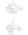
- FIG. 1st Embodiment of the fastener for accessories in this invention It is a longitudinal cross-sectional view of the fastener for accessories of FIG. It is a partially omitted isolation perspective view of the fastener for accessories of FIG. It is an external view which shows 2nd Embodiment of the fastener for accessories in this invention. It is an external view which shows 3rd Embodiment of the fastener for accessories in this invention.
- FIG. 1 shows an embodiment of the accessory using the fastener of the present invention
- FIG. 2 shows the attached state of the accessory
- FIG. 3 shows the fastener used for the accessory.
- the accessory fastener (hereinafter referred to as the fastener body 1) in the present invention is attached to the accessory body 2 consisting of a long chain-like necklace shown in FIGS. 1 and 2, and the fastener body 1 enables the accessory body 2 are annularly connected and provided detachably on the body.
- the fastener body 1 is provided with a holder 10, a flexible member 11, a closing member 12 and a spring 13.
- the holder 10 is provided with a substantially U-shaped cross section and a substantially bowl-like external appearance by using an appropriate noble metal material or metal material having a decorative property, and is provided as a side for fixing the accessory main body 2.
- An arc-shaped holding portion 20 is formed on one end side to which the accessory main body 2 is attached, and an opening 21 is provided on the opening side of the holding portion 20.
- the opening 21 is formed so that the accessory main body 2 can be attached to and detached from the holder 20 slightly larger than the thickness of the accessory main body 2, and the accessory main body 2 can be held by the holder 20 through the opening 21.
- a holding space S described later is provided between the holder 10 and the closing member 12 to which the flexible member 11 is attached, and the accessory main body 2 is attached to the holding portion 20 through the flexible member 11 in the holding space S. Be done.
- a curved end 22 forming a gentle curved surface is formed to be connected from the holding portion 20, and the accessory main body 2 can be guided to the holding portion 20 from the opening 21 through the curved end 22. ing.
- a curved portion 23 which is recessed near the center is formed.
- two communication holes 24 are formed so as to intersect the opening and closing direction of the closing member 12.
- an attachment hole 25 for attaching the fixed side of the accessory main body 2 is formed on the end side of the communication hole 24.
- the closing member 12 has a curved upper surface side and a curved lower surface side in the front view of FIG. 4 and is formed into a U-shaped cross section that can be accommodated inside the holder, and the flexible member 11 is formed inside this U-shaped portion. Is attached.
- a through hole 26 is formed at a position corresponding to the communication hole 24 of the closing member 12, and the closing member 12 is temporarily attached to the holder 10 in a state where the through hole 26 is in communication with the communication hole 24. 24, the pin 27 is inserted into the through hole 26. Both end portions of the pin 27 are fixed to the holder 10 by caulking or laser welding or the like, and the bearing portion 28 is provided.
- the closing member 12 is rotatably attached to the holder 10 as the movable side on the other end side with the opening 21 via the bearing portion 28, and the tip end side thereof is from the inside of the opening 21. It can be locked.
- the locking member 28 is rotated around and the locking of the opening 10 on the tip end side of the closing member 12 is released, opening the opening 10
- the holder 10 and the closing member 12 are respectively integrally formed by a processing means such as press processing using, for example, a thin plate-like noble metal such as 0.1 mm thick 18K or silver.
- the flexible member 11 of FIG. 5 is formed in a long shape by a flat shape including a plate-like portion 30 and a wide portion 31 wider than the plate-like portion 30 by silicone having frictional resistance.
- the plate-like portion 30 is formed to a thickness that can be fitted into the U-shaped inside of the closing member 12.
- the wide portion 31 is formed on the front and back surfaces of the front end side (right side in FIG. 4A) of the plate-like portion 30 so as to have a thickness substantially equal to the width of the closing member 12.
- An appropriate smooth convex arc portion 32 is formed on the tip end side of the wide portion 31, and a concave arc portion 33 engageable with the tip end side of the closing member 12 is formed on the rear end side of the wide portion 31. .
- the flexible member 11 is fitted to the closing member 12 with the plate-like portion 30 enclosed inside, the concave arc portion 33 engages with the tip end surface of the closing member 12, and the convex arc portion 32 of the wide portion 31 is a holding space It is attached to the closing member 12 by means such as adhesion in a state of slightly projecting (bulging) to S. Thereby, the flexible member 11 is mounted so as to protrude from at least the sandwiching side of the accessory main body 2 of the closing member 12.
- the spring 13 in FIG. 4 is a torsion coil spring, and has a coil portion 40, a free end portion 41 on one end side sandwiching the coil portion 40, and a bending portion 42 on the other end side.
- the spring 13 In the state where the coil portion 40 is attached to the shaft attachment portion 28, the free end portion 41 is in contact with the inner surface of the closing member 12, and the bending portion 42 is pierced by the soft member 11, the spring 13 is closed. They are mounted between the member 12 so as to repel each other.
- the closing member 12 is urged in the direction of closing the opening 21 by the spring 13.
- the closing member 12 is urged in the left rotation direction of FIG. 4A by the elastic force of the spring 13, and normally, the tip end side of the closing member 12 is locked in the opening 21 to close it It becomes.
- the closing member 12 and the holder 10 are pinched against each other and pressed against the elastic force of the spring 13, the soft member 11 slides on the inner periphery of the holder 10, and the closing member 12 rotates clockwise, as shown in FIG. As shown in b), the opening 21 is opened.
- the holding space S is provided as a space for holding the accessory main body 2 between the flexible member 11 and the holding portion 20, and the accessory main body 2 is held in the holding space S in the direction of the spring 13 It is possible to hold it by being done. Specifically, when the closing member 12 is pressed toward the holder 10 from the state of FIG. 4A and the closing member 12 moves into the holder 10 as shown in FIG. A sandwiching space S is provided between the and the closing member 12 via the soft member 11, and the accessory main body 2 is attached to the holding portion 20 in the sandwiching space S as shown by a two-dot chain line in FIG. By releasing the pressure between the closing member 12 and the holder 10 in this state, the accessory main body 2 is held between the holding portion 20 and the flexible member 11 by the elastic force of the spring 13.
- the accessory main body 2 shown in FIG. 1 is formed in a long chain shape with a noble metal such as gold, silver, platinum or the like, or other metal material, and a general purpose one can be used.
- the accessory body 2 has a chain element 2 a, and the chain element 2 a at one end is attached to the attachment hole 25 of the fastener body 1.
- a decorative member 50 having appropriate decorativeness is attached to the chain element 2 a on the other end side, and the decorative member 50 is formed larger than the holding space S of the fastener main body 1.
- the soft member 11 is mounted on the closing member 12 side, but if it protrudes to the holding space S side and the accessory main body 2 can be detached between the holder 10 and the closing member 12 , May be attached to the holder 10 side.
- the flexible member 11 may be provided in a compact shape that can be disposed only on the holding space S side.
- the soft member is positioned and fixed to the closing member by these locks. It becomes possible. This reduces the material of the flexible member and facilitates the installation. Furthermore, since it is not necessary to provide the spring with a bent portion for fixing to the flexible member, the degree of freedom in processing the spring is also improved.
- the soft member 11 may be a material other than silicone as long as it is a material capable of generating a suitable frictional resistance, and may be formed of, for example, rubber.
- the flexible member 11 is formed in a long shape and disposed over substantially the entire closure member 12, but if the accessory main body 2 can be gripped, only near the tip end side of the closure member 12 It may be of a shape that can be arranged.
- the accessory main body 2 is not limited to a chain shape, and may have a suitable decoration such as a string shape.
- the decorative member 50 may be removable, integrally provided, or omitted from the accessory main body 2.
- the fastener main body 1 is a fastening structure that sandwiches the accessory main body 2 in the sandwiching space S via the flexible member 11 between the holding portion 20 and the closing member 12, the fastener main body 1 is provided in an appropriate shape or any decoration
- the size of the holding space S may be appropriately set in accordance with the thickness of the accessory main body 2.
- the fastener main body 1 described above is attached to the body, first, in FIG. 1, the fastener main body 1 and the decorative member 50 are attached to the body with the fastener body 1 and the accessory main body 2 being unlocked. (The chest and abdomen), and while adjusting the length of both ends of the fastener body 1, the accessory body 2 is hung on the neck.
- the accessory body 2 After the accessory body 2 is attached, the accessory body 2 is firmly held between the flexible member 11 and the holding portion 20 by the elastic force and frictional resistance of the flexible member 11 in addition to the elastic force of the spring 13. suppress.
- the chain element 2a forming the accessory body 2 is different in thickness, a strong holding force can be exerted according to the thickness to be able to maintain the mountability, so that versatility is excellent, temporarily an external force is applied after mounting. Even if it does, the shift
- the pinched portion does not expand outward, and the compactness of the fastener main body 1 is maintained.
- the closing member 12 to which the flexible member 11 is attached can be made compact while being entirely accommodated while being stored in the inside of the holder 10, and since it does not have an outwardly pointed projection, it does not interfere with the attachment Also, it is excellent in functional beauty, such as being able to prevent clothing and hair from getting caught and misoperation.
- the attachment position and left / right length of the accessory main body 2 can be easily adjusted at the time of attachment and after attachment, and in this case, the closure member 12 and the holder 10 are pinched with a finger and pressure is applied to the accessory main body The clamping force to 2 is released, and in this state, the accessory main body 2 can be slid to the holding portion 20 to adjust the mounting position.
- the accessory body 2 can be easily adjusted without removing it, and by suppressing the sliding between the accessory body 2 and the flexible member 11, the accessory body 2 can be damaged or the consumption of the flexible member 11 can be suppressed.
- the closing member 12 Since the closing member 12 is always biased in the closing direction by the torsion coil spring 13, the closing member 12 is prevented from being loosened naturally and the opening 21 is opened, thereby preventing the accessory main body 2 from coming off. As described above, since the accessory main body 2 is held using the elastic force of the torsion coil spring 13, the holding force is maintained even when the closing member 12 is repeatedly opened and closed. In a normal state, the distal end side of the closing member 12 is locked from the inside of the opening 21 so that although the elastic force of the torsion coil spring 13 is applied to the closing member 12, the closing member 12 Prevent outward protrusion of
- the soft member 11 Since the soft member 11 is formed into a flat shape and is fitted into the inside of the closing member 12 while being enclosed, the soft member 11 is formed on the inside of the closing member 12 simultaneously with the forming process of the closing member 12 by pressing or the like. It can be fixed in place. Moreover, since the plate-like portion 30 of the flexible member 11 is formed in a long shape and the plate-like portion 30 is fitted inside the closing member 12, the contact area between the flexible member 11 and the closing member 12 is increased. Thus, the displacement of the flexible member 11 after the fixing is prevented, and the durability against repeated use is enhanced. Furthermore, productivity, assemblability and processability are also good.
- FIG. 6 2nd Embodiment of the fastener for accessories in this invention is shown.
- the same parts as those of the above-described embodiments are denoted by the same reference numerals, and the description thereof will be omitted.
- a grooved portion is formed inside the holding portion 61, and the flexible member 62 made of silicone is accommodated in the grooved portion.
- the flexible member 62 made of silicone is accommodated in the grooved portion.
- a plurality of claws are provided at both edges of the groove, and the flexible members 62 are mounted in a state fixed in the holding portion 61 by folding the claws after the soft members 62 are accommodated. Ru.
- a smooth rounded surface 63 is provided on the inner peripheral side of the flexible member 62 after attachment to the holding portion 61, and a space for attaching the accessory main body 2 is provided by the rounded surface 63.
- the flexible member 62 is mounted on the holder 10 on the fixed side, and the holding space S in which the accessory main body 2 is held between the flexible member 62 and the closing member 12 is provided.
- a spring which is a plate spring (not shown), is mounted between the holder 10 and the closing member 12, and the closing member 12 is biased in the direction of closing the opening 21 by the elastic force of the spring.
- the accessory main body 2 By closing the opening 21 by pressing the closing member 12 so as to pinch the closing member 12, the accessory main body 2 can be held between the closing member 12 and the flexible member 62 of the holder 10 as in the above-described case.
- 6A shows the closed state of the fastener main body 60
- FIG. 6B shows the open state of the fastener main body 60, and the embodiment according to the closed state of FIG. 6A.
- the accessory main body 2 can be firmly held.
- a leaf spring is used as a spring as in this example, it is possible to exert the same elastic force as the torsion coil spring while suppressing the cost compared to the torsion coil spring.
- the fastener main body 70 is provided by shortening the fastener main body 60 of FIG. 6 in the length direction, and also in this case, the fastener main body 60 is shown in the closed state of FIG. 7A and in the open state of FIG.
- the closing member 12 can be pressed so as to open and close the opening / closing portion.
- the closure body 60 can be made more compact than the fastener body 60 of FIG.
Landscapes
- Adornments (AREA)
Abstract
L'invention concerne: un fermoir pour accessoires avec lequel il est possible d'attacher et d'enlever facilement un accessoire long sur et hors du corps par une simple pression du doigt tout en ajustant une position de serrage, et même lorsque l'accessoire est une chaîne étroite, il est possible de serrer fermement cet accessoire sans endommager l'accessoire, et maintenir la position attachée pour empêcher le glissement, la partie amovible étant compactée pour montrer une excellente décoration; et un accessoire utilisant celui-ci. Un corps d'accessoire (2) comporte: un élément de retenue côté fixe (10) ayant une partie de retenue (20) retenue par l'intermédiaire d'une ouverture (21); un élément de fermeture côté mobile (12) fixé rotatif au dispositif de retenue (10) par l'intermédiaire d'un support axial (28), pour un verrouillage à partir de l'intérieur de l'ouverture (21) et se plaçant dans un état fermé; un élément souple (11) monté sur au moins le côté de l'élément de fermeture (12) qui maintient le corps d'accessoire (2); et un ressort (13) monté dans un état élastique entre l'élément de retenue (10) et l'élément de fermeture (12), pour solliciter l'élément de fermeture (12) dans la direction de fermeture de l'ouverture (21). Un espace de maintien (S) est disposé entre l'élément souple (11) et la partie de retenue (20), dans lequel l'espace entre le corps d'accessoire (2) est maintenu dans la direction élastique du ressort (13).
Priority Applications (4)
| Application Number | Priority Date | Filing Date | Title |
|---|---|---|---|
| CN201780002154.6A CN109068817A (zh) | 2017-04-10 | 2017-07-14 | 人身装饰品用卡扣和使用其的人身装饰品 |
| US15/736,584 US10709217B2 (en) | 2017-04-10 | 2017-07-14 | Personal-ornament clasp and personal ornament using the same |
| EP17811174.6A EP3415032B1 (fr) | 2017-04-10 | 2017-07-14 | Fermoir pour accessoires et accessoire l'utilisant |
| JP2017558754A JP6596513B2 (ja) | 2017-04-10 | 2017-07-14 | 装身具用留め具とこれを用いた装身具 |
Applications Claiming Priority (2)
| Application Number | Priority Date | Filing Date | Title |
|---|---|---|---|
| JP2017-077500 | 2017-04-10 | ||
| JP2017077500 | 2017-04-10 |
Publications (1)
| Publication Number | Publication Date |
|---|---|
| WO2018189918A1 true WO2018189918A1 (fr) | 2018-10-18 |
Family
ID=63792646
Family Applications (1)
| Application Number | Title | Priority Date | Filing Date |
|---|---|---|---|
| PCT/JP2017/025703 WO2018189918A1 (fr) | 2017-04-10 | 2017-07-14 | Fermoir pour accessoires et accessoire l'utilisant |
Country Status (5)
| Country | Link |
|---|---|
| US (1) | US10709217B2 (fr) |
| EP (1) | EP3415032B1 (fr) |
| JP (1) | JP6596513B2 (fr) |
| CN (1) | CN109068817A (fr) |
| WO (1) | WO2018189918A1 (fr) |
Families Citing this family (5)
| Publication number | Priority date | Publication date | Assignee | Title |
|---|---|---|---|---|
| US11317684B1 (en) * | 2018-10-25 | 2022-05-03 | Misa Design, LLC | Necklace having integrated pendant anchor |
| CN109757836B (zh) * | 2019-01-03 | 2020-12-25 | 郑海宁 | 一种链扣及其制造设备和制造方法 |
| US10858222B1 (en) | 2019-06-18 | 2020-12-08 | Christopher Laarman | Couplers with partially open gates |
| US20210259165A1 (en) * | 2020-02-24 | 2021-08-26 | Lillian C. Rauch | Clothing and fashion accessories for plants |
| USD989657S1 (en) * | 2022-02-26 | 2023-06-20 | Cartier International Ag | Charm |
Citations (7)
| Publication number | Priority date | Publication date | Assignee | Title |
|---|---|---|---|---|
| JPH03132896A (ja) | 1989-10-19 | 1991-06-06 | Fuji Electric Co Ltd | 飲料自動販売機の飲料水殺菌装置 |
| JP3041020U (ja) * | 1997-02-28 | 1997-09-05 | 株式会社ムラオ | 長さ調節式ネックレス |
| JPH09271407A (ja) * | 1996-04-04 | 1997-10-21 | Yoshiaki Kanamori | 装身具用ジョイント |
| JPH10295421A (ja) | 1997-05-01 | 1998-11-10 | J C S:Kk | 装飾チエーン用の装飾具と止め具 |
| JP2001224412A (ja) * | 2000-02-18 | 2001-08-21 | Kosaikogei Co Ltd | 装身具用止め金具 |
| JP2006325657A (ja) * | 2005-05-23 | 2006-12-07 | Yasuo Kawahara | 装身具用留め具 |
| WO2016121088A1 (fr) * | 2015-01-30 | 2016-08-04 | 雅弘 星野 | Élément de fixation |
Family Cites Families (8)
| Publication number | Priority date | Publication date | Assignee | Title |
|---|---|---|---|---|
| US731162A (en) * | 1902-12-31 | 1903-06-16 | Charles W Carter | Snap-hook. |
| US1746054A (en) * | 1927-02-09 | 1930-02-04 | Ridabock Alice Budd | Holding device for necklaces |
| US4628708A (en) * | 1983-02-24 | 1986-12-16 | Ivey Alma T | Jewelry chain organizer |
| US4754534A (en) * | 1987-01-15 | 1988-07-05 | Helwick Carol S | Jewelry clip |
| US5117539A (en) * | 1991-09-03 | 1992-06-02 | Shrader James P | Clasp mechanism |
| US5687585A (en) * | 1996-02-09 | 1997-11-18 | Ferrell; Kathryn L. | Necklace chain separation device and a multiple strand necklace unit |
| US6308385B1 (en) * | 1999-11-29 | 2001-10-30 | Peter Franklin Ball | Jewelry clasp |
| US9777763B2 (en) * | 2010-09-14 | 2017-10-03 | Lucy A. Mitchell | Hook with magnetic closure |
-
2017
- 2017-07-14 JP JP2017558754A patent/JP6596513B2/ja active Active
- 2017-07-14 EP EP17811174.6A patent/EP3415032B1/fr active Active
- 2017-07-14 WO PCT/JP2017/025703 patent/WO2018189918A1/fr unknown
- 2017-07-14 US US15/736,584 patent/US10709217B2/en active Active
- 2017-07-14 CN CN201780002154.6A patent/CN109068817A/zh active Pending
Patent Citations (7)
| Publication number | Priority date | Publication date | Assignee | Title |
|---|---|---|---|---|
| JPH03132896A (ja) | 1989-10-19 | 1991-06-06 | Fuji Electric Co Ltd | 飲料自動販売機の飲料水殺菌装置 |
| JPH09271407A (ja) * | 1996-04-04 | 1997-10-21 | Yoshiaki Kanamori | 装身具用ジョイント |
| JP3041020U (ja) * | 1997-02-28 | 1997-09-05 | 株式会社ムラオ | 長さ調節式ネックレス |
| JPH10295421A (ja) | 1997-05-01 | 1998-11-10 | J C S:Kk | 装飾チエーン用の装飾具と止め具 |
| JP2001224412A (ja) * | 2000-02-18 | 2001-08-21 | Kosaikogei Co Ltd | 装身具用止め金具 |
| JP2006325657A (ja) * | 2005-05-23 | 2006-12-07 | Yasuo Kawahara | 装身具用留め具 |
| WO2016121088A1 (fr) * | 2015-01-30 | 2016-08-04 | 雅弘 星野 | Élément de fixation |
Also Published As
| Publication number | Publication date |
|---|---|
| US20180352917A1 (en) | 2018-12-13 |
| EP3415032A1 (fr) | 2018-12-19 |
| US10709217B2 (en) | 2020-07-14 |
| JPWO2018189918A1 (ja) | 2019-06-27 |
| JP6596513B2 (ja) | 2019-10-23 |
| EP3415032B1 (fr) | 2020-02-12 |
| EP3415032A4 (fr) | 2019-04-24 |
| CN109068817A (zh) | 2018-12-21 |
Similar Documents
| Publication | Publication Date | Title |
|---|---|---|
| WO2018189918A1 (fr) | Fermoir pour accessoires et accessoire l'utilisant | |
| GB2325488A (en) | Retaining clip | |
| JP2001349308A (ja) | プラスチック製挟持具 | |
| US8256070B2 (en) | Split arm clip | |
| TWI461159B (zh) | 卡扣具 | |
| JP3129475U (ja) | 吊下げ式装身具 | |
| JP4431066B2 (ja) | 耳止具 | |
| JPH09299117A (ja) | 装身具の止め金具 | |
| JP2017202081A (ja) | 装身具用留め具とこれを用いた装身具 | |
| JP6679953B2 (ja) | バンド、美錠付き時計バンドおよび時計 | |
| CN220898110U (zh) | 一种皮带扣的弹性定位结构 | |
| JP2016043109A (ja) | 耳用装身具 | |
| JP3138571U (ja) | 装身具の留め具 | |
| JP3131016U (ja) | 装身具用連結金具 | |
| JP3166723U (ja) | 装身具用引き輪の装飾構造 | |
| US643317A (en) | Garment-supporter. | |
| JP3726157B2 (ja) | 合成樹脂製クリップ | |
| JP2012125267A (ja) | 装身具兼襟巻き保持具 | |
| JPH09191912A (ja) | 装身具用留め金具 | |
| JP3060035U (ja) | 装身具の止め金具 | |
| JP2007195606A (ja) | 装身具用留め具及びこれを備える装身具 | |
| JP3119007U (ja) | ブレスレット装着の際の補助具 | |
| JP2005118324A (ja) | ネックレスのずれ防止具及び該ずれ防止具を備えたネックレスセット | |
| WO2021117152A1 (fr) | Élément de fixation pour accessoire à porter sur soi | |
| JP3052869U (ja) | 装身具用留め具 |
Legal Events
| Date | Code | Title | Description |
|---|---|---|---|
| ENP | Entry into the national phase |
Ref document number: 2017558754 Country of ref document: JP Kind code of ref document: A |
|
| 121 | Ep: the epo has been informed by wipo that ep was designated in this application |
Ref document number: 17811174 Country of ref document: EP Kind code of ref document: A1 |
|
| NENP | Non-entry into the national phase |
Ref country code: DE |