WO2018189918A1 - Clasp for accessories and accessory using same - Google Patents
Clasp for accessories and accessory using same Download PDFInfo
- Publication number
- WO2018189918A1 WO2018189918A1 PCT/JP2017/025703 JP2017025703W WO2018189918A1 WO 2018189918 A1 WO2018189918 A1 WO 2018189918A1 JP 2017025703 W JP2017025703 W JP 2017025703W WO 2018189918 A1 WO2018189918 A1 WO 2018189918A1
- Authority
- WO
- WIPO (PCT)
- Prior art keywords
- accessory
- closing member
- fastener
- opening
- holder
- Prior art date
Links
Images


Classifications
-
- A—HUMAN NECESSITIES
- A44—HABERDASHERY; JEWELLERY
- A44C—PERSONAL ADORNMENTS, e.g. JEWELLERY; COINS
- A44C11/00—Watch chains; Ornamental chains
- A44C11/005—Watch chains; Ornamental chains with friction boxes adjustments
-
- A—HUMAN NECESSITIES
- A44—HABERDASHERY; JEWELLERY
- A44C—PERSONAL ADORNMENTS, e.g. JEWELLERY; COINS
- A44C25/00—Miscellaneous fancy ware for personal wear, e.g. pendants, crosses, crucifixes, charms
- A44C25/001—Pendants
-
- A—HUMAN NECESSITIES
- A44—HABERDASHERY; JEWELLERY
- A44C—PERSONAL ADORNMENTS, e.g. JEWELLERY; COINS
- A44C5/00—Bracelets; Wrist-watch straps; Fastenings for bracelets or wrist-watch straps
- A44C5/18—Fasteners for straps, chains or the like
- A44C5/20—Fasteners for straps, chains or the like for open straps, chains or the like
- A44C5/2019—Hooks
- A44C5/2033—Hooks provided with pivoting closure means
- A44C5/2038—Swivels
-
- A—HUMAN NECESSITIES
- A44—HABERDASHERY; JEWELLERY
- A44C—PERSONAL ADORNMENTS, e.g. JEWELLERY; COINS
- A44C15/00—Other forms of jewellery
- A44C15/0045—Jewellery specially adapted to be worn on a specific part of the body not fully provided for in groups A44C1/00 - A44C9/00
- A44C15/005—Necklaces
-
- A—HUMAN NECESSITIES
- A44—HABERDASHERY; JEWELLERY
- A44D—INDEXING SCHEME RELATING TO BUTTONS, PINS, BUCKLES OR SLIDE FASTENERS, AND TO JEWELLERY, BRACELETS OR OTHER PERSONAL ADORNMENTS
- A44D2200/00—General types of fasteners
- A44D2200/10—Details of construction
-
- Y—GENERAL TAGGING OF NEW TECHNOLOGICAL DEVELOPMENTS; GENERAL TAGGING OF CROSS-SECTIONAL TECHNOLOGIES SPANNING OVER SEVERAL SECTIONS OF THE IPC; TECHNICAL SUBJECTS COVERED BY FORMER USPC CROSS-REFERENCE ART COLLECTIONS [XRACs] AND DIGESTS
- Y10—TECHNICAL SUBJECTS COVERED BY FORMER USPC
- Y10T—TECHNICAL SUBJECTS COVERED BY FORMER US CLASSIFICATION
- Y10T24/00—Buckles, buttons, clasps, etc.
- Y10T24/45—Separable-fastener or required component thereof [e.g., projection and cavity to complete interlock]
- Y10T24/45225—Separable-fastener or required component thereof [e.g., projection and cavity to complete interlock] including member having distinct formations and mating member selectively interlocking therewith
- Y10T24/45272—Projection passes through cavity then moves toward noninserted portion of its member to complete interlock [e.g., snap hook]
- Y10T24/45288—Hook type projection member
- Y10T24/45304—Noninserted portion of projection member includes movably connected gate for closing access throat
- Y10T24/45319—Pivotally connected gate
- Y10T24/45335—Pivotally connected gate having means biasing gate about pivot
- Y10T24/4534—Pivotally connected gate having means biasing gate about pivot and position locking-means for gate
Definitions
- the present invention relates to an accessory fastener for annularly locking an accessory such as a necklace when attached to a body, and more particularly to an accessory capable of attaching a long chain-like accessory to the body while adjusting a fastening position.
- the present invention relates to a fastener and an accessory using the same.
- the decorative device of patent document 1 is disclosed as an accessory which can adjust the fastening position of this kind.
- This accessory is an accessory for a decoration chain of a necklace, and a cylinder made of a resin material having elasticity is provided in the decoration.
- the small hole of the cylinder is provided smaller than the diameter of the decoration chain, and this structure allows the end of the decoration chain to be inserted into the cylinder and allows the decoration chain to slide in a locked state relative to the cylinder. The locking position is changed to adjust the fastening position at the time of mounting.
- the fastener for the accessory of Patent Document 2 has a decorative member main body having a decoration on the surface, and the decorative member main body is provided with first and second engagement members engaged with each other.
- the second engagement member is rotatably provided on the first engagement member about a fulcrum, and a magnet is provided on one engagement member and a magnet or a metal member is provided on the other engagement member.
- the engagement members are provided so as to be engageable, and the elongated accessory main body is fastened in the space between the engagement members in a state where the fastening position can be adjusted.
- a necklace fastener consisting of a plate and slide parts having a ring ring and a hole, which is widely used, inserts the pin of the ring into the hole of the plate while pulling the pin of the ring, and further, The slide parts have to be adjusted to adjust the annulus ring of the chain, forcing the work of fasteners to be extremely laborious, especially when using an elderly necklace, these points are a serious issue,
- the development of a fastener for a necklace that eliminates these problems is eagerly awaited.
- the fastener for the accessory of Patent Document 2 since the decorative member main body is provided with the engaging magnet and the metal member, the decorative member main body is enlarged and the integrity with the chain is lost, and the decorativeness is impaired. It was In this fastener, the accessory body is provided by a pearl necklace, and the fastening position can be adjusted because the pearl is sized so as not to pass through the space provided by the arc portion of the engagement member. There is. As described above, since this fastener does not have a structure in which the accessory body is directly pinched and fixed by the engaging member, in the case where the accessory body is a thin chain, a loose position occurs with the accessory body. There is a possibility that the mounting performance may be lowered due to shifting.
- the present invention has been developed in view of the above situation, and the purpose of the present invention is to solve the troublesome handling of the conventional fastener at once, and one-touch while adjusting the fastening position. It is a fastener for accessories that can easily attach and detach a long accessory to the body, and even when the accessory is a thin chain, it is possible to prevent displacement by holding the attachment position firmly without damaging the accessory without damaging the accessory. SUMMARY OF THE INVENTION An object of the present invention is to provide an accessory fastener which makes the detachable portion compact and exhibits excellent decorativeness, and an accessory using the same.
- the invention according to claim 1 is a holder on the fixed side having an arc-shaped holding portion at one end side of which an elongated chain-like accessory body is held via an opening, and an opening
- the movable side closing member which is rotatably attached to the holder via the bearing at the other end side of the side and is locked from the inside of the opening to make the closed state, and at least the accessory of the closing member
- the soft member is silicone or rubber having a frictional resistance, and is a fastener for accessories that is mounted in a state of slightly protruding from the closing member to the holding space.
- the invention according to claim 3 is the fastener for an accessory, wherein the flexible member is formed into a flat shape and is fitted inside the closing member in a state of being surrounded.
- the invention according to claim 4 is that the holder on the fixed side has an arc-shaped holding portion at one end side in which the long chain-like accessory body is held via the opening, and the other end on the opening side
- a movable closing member which is rotatably attached to the holder via the bearing portion and which is locked from the inside to the closed state to be closed, and a flexible member mounted on the inner periphery of the holding portion;
- the soft member is an accessory fastener made of silicone or rubber having a frictional resistance.
- the invention according to claim 6 is an accessory using the accessory fastener in which the accessory fastener is provided on one end side of the accessory body.
- the invention according to claim 7 is an accessory using an accessory fastener in which a decorative member larger than the holding space is attached to the other end side of the accessory body.
- the fixture on the fixed side having the arc-like holding part at one end through the opening and A resilient member which is locked from the inside of the opening through the bearing portion to be in a closed state, a flexible member mounted on the nipping side of the resilient member, and a holder and the resilient member in the direction of closing A spring is provided, and the accessory body is provided in the holding space between the flexible member and the holding portion so as to be able to hold the accessory main body by the elastic force of the spring, whereby the holder, the closing against the elastic force of the spring.
- a light pressing force is applied to pinch the member with a finger to open the holding space, and the accessory body is dropped from the opening into the holding space, whereby the desired position of the accessory body can be set.
- the elongated accessory body can be easily mounted with one touch while adjusting to an arbitrary fastening position.
- the accessory main body is held between the soft member and the holding part by the elastic force of the spring, and even when the accessory main body is a thin chain, the elastic force and frictional resistance of the soft member without damaging the accessory main body. Hold the mounting position of the accessory main body firmly to prevent shifting or falling off.
- the combination of the holding portion and the closing member makes the whole thin and long and can improve the integrity with the chain, and further, the holding member and the closing member do not expand outward after the accessory body is held, and the whole decoration It is possible to cope with chains of different thickness while maintaining its properties, and provide a compact accessory fastener with excellent functional beauty.
- the pull ring, plate and slide parts which are essential parts for the conventional fasteners, are completely unnecessary, and the complicated position of the chain can be extremely easily achieved without the need for the conventional troublesome work.
- it is possible to easily fasten the fastener with one action and it is possible to provide a fastener and its jewelry of extremely high commercial value as compared with the prior art.
- the accessory main body can be attached and detached without damaging the surface. Since the soft member is mounted in a slightly projecting state in the holding space, the soft member can be held in a reliable contact with the accessory body while holding the accessory body firmly by the frictional resistance of the soft member It can prevent slippage and falling off and maintain fit to the body.
- the soft member can be attached to the inside of the closing member at the same time when the closing member is formed by pressing or the like, mass production can be achieved while reducing the number of parts and the number of processing steps. At that time, the soft member can be attached at the correct position, and the loosening and falling off after the attachment can be prevented, and the assembly becomes easy.
- the holder on the fixed side having the arc-shaped holding portion at one end side through the opening and the lock from the inside of the opening through the shaft attachment portion to be in the closed state
- the elongated accessory body can be easily mounted with one touch while adjusting to an arbitrary fastening position.
- the accessory main body is held between the soft member and the holding part, and even when the accessory main body is a thin chain, it is strongly held through the elastic force and frictional resistance of the soft member without damaging the accessory main body.
- the attachment position of the accessory main body is held to prevent shifting or falling off.
- the combination of the holding portion and the closing member makes the whole thin and long and can improve the integrity with the chain, and further, the holding member and the closing member do not expand outward after the accessory body is held, and the whole decoration It is possible to correspond to chains of different thickness while maintaining the quality, and can provide compact fasteners with excellent functional beauty.
- the accessory main body can be attached and detached without damaging the surface. After the attachment main body is attached, the attachment main body is firmly held by the frictional resistance of the soft member to prevent the shift and the detachment after the attachment, and the fit to the body can be maintained.
- the accessory main body can be easily attached to and detached from the body by one touch while adjusting the fastening position, and after wearing, the wearing state according to the body can be maintained.
- the width of the decoration is expanded.
- the decoration member larger than the holding space on the other end side of the fastener of the accessory body, temporarily, the force in the disengaging direction is applied to the other end side after being attached to the body. Even when it is added, the decorative member is locked to the holder to prevent it from coming off and to prevent it from falling off from the body, and the decorative member further enhances the decorativeness as an accessory.
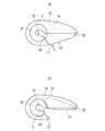
- FIG. 1st Embodiment of the fastener for accessories in this invention It is a longitudinal cross-sectional view of the fastener for accessories of FIG. It is a partially omitted isolation perspective view of the fastener for accessories of FIG. It is an external view which shows 2nd Embodiment of the fastener for accessories in this invention. It is an external view which shows 3rd Embodiment of the fastener for accessories in this invention.
- FIG. 1 shows an embodiment of the accessory using the fastener of the present invention
- FIG. 2 shows the attached state of the accessory
- FIG. 3 shows the fastener used for the accessory.
- the accessory fastener (hereinafter referred to as the fastener body 1) in the present invention is attached to the accessory body 2 consisting of a long chain-like necklace shown in FIGS. 1 and 2, and the fastener body 1 enables the accessory body 2 are annularly connected and provided detachably on the body.
- the fastener body 1 is provided with a holder 10, a flexible member 11, a closing member 12 and a spring 13.
- the holder 10 is provided with a substantially U-shaped cross section and a substantially bowl-like external appearance by using an appropriate noble metal material or metal material having a decorative property, and is provided as a side for fixing the accessory main body 2.
- An arc-shaped holding portion 20 is formed on one end side to which the accessory main body 2 is attached, and an opening 21 is provided on the opening side of the holding portion 20.
- the opening 21 is formed so that the accessory main body 2 can be attached to and detached from the holder 20 slightly larger than the thickness of the accessory main body 2, and the accessory main body 2 can be held by the holder 20 through the opening 21.
- a holding space S described later is provided between the holder 10 and the closing member 12 to which the flexible member 11 is attached, and the accessory main body 2 is attached to the holding portion 20 through the flexible member 11 in the holding space S. Be done.
- a curved end 22 forming a gentle curved surface is formed to be connected from the holding portion 20, and the accessory main body 2 can be guided to the holding portion 20 from the opening 21 through the curved end 22. ing.
- a curved portion 23 which is recessed near the center is formed.
- two communication holes 24 are formed so as to intersect the opening and closing direction of the closing member 12.
- an attachment hole 25 for attaching the fixed side of the accessory main body 2 is formed on the end side of the communication hole 24.
- the closing member 12 has a curved upper surface side and a curved lower surface side in the front view of FIG. 4 and is formed into a U-shaped cross section that can be accommodated inside the holder, and the flexible member 11 is formed inside this U-shaped portion. Is attached.
- a through hole 26 is formed at a position corresponding to the communication hole 24 of the closing member 12, and the closing member 12 is temporarily attached to the holder 10 in a state where the through hole 26 is in communication with the communication hole 24. 24, the pin 27 is inserted into the through hole 26. Both end portions of the pin 27 are fixed to the holder 10 by caulking or laser welding or the like, and the bearing portion 28 is provided.
- the closing member 12 is rotatably attached to the holder 10 as the movable side on the other end side with the opening 21 via the bearing portion 28, and the tip end side thereof is from the inside of the opening 21. It can be locked.
- the locking member 28 is rotated around and the locking of the opening 10 on the tip end side of the closing member 12 is released, opening the opening 10
- the holder 10 and the closing member 12 are respectively integrally formed by a processing means such as press processing using, for example, a thin plate-like noble metal such as 0.1 mm thick 18K or silver.
- the flexible member 11 of FIG. 5 is formed in a long shape by a flat shape including a plate-like portion 30 and a wide portion 31 wider than the plate-like portion 30 by silicone having frictional resistance.
- the plate-like portion 30 is formed to a thickness that can be fitted into the U-shaped inside of the closing member 12.
- the wide portion 31 is formed on the front and back surfaces of the front end side (right side in FIG. 4A) of the plate-like portion 30 so as to have a thickness substantially equal to the width of the closing member 12.
- An appropriate smooth convex arc portion 32 is formed on the tip end side of the wide portion 31, and a concave arc portion 33 engageable with the tip end side of the closing member 12 is formed on the rear end side of the wide portion 31. .
- the flexible member 11 is fitted to the closing member 12 with the plate-like portion 30 enclosed inside, the concave arc portion 33 engages with the tip end surface of the closing member 12, and the convex arc portion 32 of the wide portion 31 is a holding space It is attached to the closing member 12 by means such as adhesion in a state of slightly projecting (bulging) to S. Thereby, the flexible member 11 is mounted so as to protrude from at least the sandwiching side of the accessory main body 2 of the closing member 12.
- the spring 13 in FIG. 4 is a torsion coil spring, and has a coil portion 40, a free end portion 41 on one end side sandwiching the coil portion 40, and a bending portion 42 on the other end side.
- the spring 13 In the state where the coil portion 40 is attached to the shaft attachment portion 28, the free end portion 41 is in contact with the inner surface of the closing member 12, and the bending portion 42 is pierced by the soft member 11, the spring 13 is closed. They are mounted between the member 12 so as to repel each other.
- the closing member 12 is urged in the direction of closing the opening 21 by the spring 13.
- the closing member 12 is urged in the left rotation direction of FIG. 4A by the elastic force of the spring 13, and normally, the tip end side of the closing member 12 is locked in the opening 21 to close it It becomes.
- the closing member 12 and the holder 10 are pinched against each other and pressed against the elastic force of the spring 13, the soft member 11 slides on the inner periphery of the holder 10, and the closing member 12 rotates clockwise, as shown in FIG. As shown in b), the opening 21 is opened.
- the holding space S is provided as a space for holding the accessory main body 2 between the flexible member 11 and the holding portion 20, and the accessory main body 2 is held in the holding space S in the direction of the spring 13 It is possible to hold it by being done. Specifically, when the closing member 12 is pressed toward the holder 10 from the state of FIG. 4A and the closing member 12 moves into the holder 10 as shown in FIG. A sandwiching space S is provided between the and the closing member 12 via the soft member 11, and the accessory main body 2 is attached to the holding portion 20 in the sandwiching space S as shown by a two-dot chain line in FIG. By releasing the pressure between the closing member 12 and the holder 10 in this state, the accessory main body 2 is held between the holding portion 20 and the flexible member 11 by the elastic force of the spring 13.
- the accessory main body 2 shown in FIG. 1 is formed in a long chain shape with a noble metal such as gold, silver, platinum or the like, or other metal material, and a general purpose one can be used.
- the accessory body 2 has a chain element 2 a, and the chain element 2 a at one end is attached to the attachment hole 25 of the fastener body 1.
- a decorative member 50 having appropriate decorativeness is attached to the chain element 2 a on the other end side, and the decorative member 50 is formed larger than the holding space S of the fastener main body 1.
- the soft member 11 is mounted on the closing member 12 side, but if it protrudes to the holding space S side and the accessory main body 2 can be detached between the holder 10 and the closing member 12 , May be attached to the holder 10 side.
- the flexible member 11 may be provided in a compact shape that can be disposed only on the holding space S side.
- the soft member is positioned and fixed to the closing member by these locks. It becomes possible. This reduces the material of the flexible member and facilitates the installation. Furthermore, since it is not necessary to provide the spring with a bent portion for fixing to the flexible member, the degree of freedom in processing the spring is also improved.
- the soft member 11 may be a material other than silicone as long as it is a material capable of generating a suitable frictional resistance, and may be formed of, for example, rubber.
- the flexible member 11 is formed in a long shape and disposed over substantially the entire closure member 12, but if the accessory main body 2 can be gripped, only near the tip end side of the closure member 12 It may be of a shape that can be arranged.
- the accessory main body 2 is not limited to a chain shape, and may have a suitable decoration such as a string shape.
- the decorative member 50 may be removable, integrally provided, or omitted from the accessory main body 2.
- the fastener main body 1 is a fastening structure that sandwiches the accessory main body 2 in the sandwiching space S via the flexible member 11 between the holding portion 20 and the closing member 12, the fastener main body 1 is provided in an appropriate shape or any decoration
- the size of the holding space S may be appropriately set in accordance with the thickness of the accessory main body 2.
- the fastener main body 1 described above is attached to the body, first, in FIG. 1, the fastener main body 1 and the decorative member 50 are attached to the body with the fastener body 1 and the accessory main body 2 being unlocked. (The chest and abdomen), and while adjusting the length of both ends of the fastener body 1, the accessory body 2 is hung on the neck.
- the accessory body 2 After the accessory body 2 is attached, the accessory body 2 is firmly held between the flexible member 11 and the holding portion 20 by the elastic force and frictional resistance of the flexible member 11 in addition to the elastic force of the spring 13. suppress.
- the chain element 2a forming the accessory body 2 is different in thickness, a strong holding force can be exerted according to the thickness to be able to maintain the mountability, so that versatility is excellent, temporarily an external force is applied after mounting. Even if it does, the shift
- the pinched portion does not expand outward, and the compactness of the fastener main body 1 is maintained.
- the closing member 12 to which the flexible member 11 is attached can be made compact while being entirely accommodated while being stored in the inside of the holder 10, and since it does not have an outwardly pointed projection, it does not interfere with the attachment Also, it is excellent in functional beauty, such as being able to prevent clothing and hair from getting caught and misoperation.
- the attachment position and left / right length of the accessory main body 2 can be easily adjusted at the time of attachment and after attachment, and in this case, the closure member 12 and the holder 10 are pinched with a finger and pressure is applied to the accessory main body The clamping force to 2 is released, and in this state, the accessory main body 2 can be slid to the holding portion 20 to adjust the mounting position.
- the accessory body 2 can be easily adjusted without removing it, and by suppressing the sliding between the accessory body 2 and the flexible member 11, the accessory body 2 can be damaged or the consumption of the flexible member 11 can be suppressed.
- the closing member 12 Since the closing member 12 is always biased in the closing direction by the torsion coil spring 13, the closing member 12 is prevented from being loosened naturally and the opening 21 is opened, thereby preventing the accessory main body 2 from coming off. As described above, since the accessory main body 2 is held using the elastic force of the torsion coil spring 13, the holding force is maintained even when the closing member 12 is repeatedly opened and closed. In a normal state, the distal end side of the closing member 12 is locked from the inside of the opening 21 so that although the elastic force of the torsion coil spring 13 is applied to the closing member 12, the closing member 12 Prevent outward protrusion of
- the soft member 11 Since the soft member 11 is formed into a flat shape and is fitted into the inside of the closing member 12 while being enclosed, the soft member 11 is formed on the inside of the closing member 12 simultaneously with the forming process of the closing member 12 by pressing or the like. It can be fixed in place. Moreover, since the plate-like portion 30 of the flexible member 11 is formed in a long shape and the plate-like portion 30 is fitted inside the closing member 12, the contact area between the flexible member 11 and the closing member 12 is increased. Thus, the displacement of the flexible member 11 after the fixing is prevented, and the durability against repeated use is enhanced. Furthermore, productivity, assemblability and processability are also good.
- FIG. 6 2nd Embodiment of the fastener for accessories in this invention is shown.
- the same parts as those of the above-described embodiments are denoted by the same reference numerals, and the description thereof will be omitted.
- a grooved portion is formed inside the holding portion 61, and the flexible member 62 made of silicone is accommodated in the grooved portion.
- the flexible member 62 made of silicone is accommodated in the grooved portion.
- a plurality of claws are provided at both edges of the groove, and the flexible members 62 are mounted in a state fixed in the holding portion 61 by folding the claws after the soft members 62 are accommodated. Ru.
- a smooth rounded surface 63 is provided on the inner peripheral side of the flexible member 62 after attachment to the holding portion 61, and a space for attaching the accessory main body 2 is provided by the rounded surface 63.
- the flexible member 62 is mounted on the holder 10 on the fixed side, and the holding space S in which the accessory main body 2 is held between the flexible member 62 and the closing member 12 is provided.
- a spring which is a plate spring (not shown), is mounted between the holder 10 and the closing member 12, and the closing member 12 is biased in the direction of closing the opening 21 by the elastic force of the spring.
- the accessory main body 2 By closing the opening 21 by pressing the closing member 12 so as to pinch the closing member 12, the accessory main body 2 can be held between the closing member 12 and the flexible member 62 of the holder 10 as in the above-described case.
- 6A shows the closed state of the fastener main body 60
- FIG. 6B shows the open state of the fastener main body 60, and the embodiment according to the closed state of FIG. 6A.
- the accessory main body 2 can be firmly held.
- a leaf spring is used as a spring as in this example, it is possible to exert the same elastic force as the torsion coil spring while suppressing the cost compared to the torsion coil spring.
- the fastener main body 70 is provided by shortening the fastener main body 60 of FIG. 6 in the length direction, and also in this case, the fastener main body 60 is shown in the closed state of FIG. 7A and in the open state of FIG.
- the closing member 12 can be pressed so as to open and close the opening / closing portion.
- the closure body 60 can be made more compact than the fastener body 60 of FIG.
Abstract
Provided are: a clasp for accessories with which it is possible to easily attach and remove a long accessory to and from the body by a touch of a finger while adjusting a clasping position, and even when the accessory is a narrow chain, it is possible to firmly clamp this accessory without damaging the accessory, and retain the attached position to prevent slippage, the removable part being compacted to exhibit excellent decorativeness; and an accessory using same. An accessory body (2) is provided with: a stationary-side retainer (10) having a retaining part (20) retained via an opening (21); a movable-side closing member (12) rotatably attached to the retainer (10) via an axial support (28), for locking from the inside of the opening (21) and placing into a closed state; a flexible member (11) mounted to at least the side of the closing member (12) that holds the accessory body (2); and a spring (13) mounted in a resilient state between the retainer (10) and the closing member (12), for biasing the closing member (12) in the closing direction of the opening (21). A holding space (S) is provided between the flexible member (11) and the retaining part (20), in which space the accessory body (2) is held in the resilient direction of the spring (13).
Description
本発明は、ネックレスなどの装身具を身体に装着する際に環状に係止するための装身具用留め具に関し、特に、留め位置を調節しながら長尺のチェーン状の装身具を身体に装着できる装身具用留め具とこれを用いた装身具に関する。
The present invention relates to an accessory fastener for annularly locking an accessory such as a necklace when attached to a body, and more particularly to an accessory capable of attaching a long chain-like accessory to the body while adjusting a fastening position. The present invention relates to a fastener and an accessory using the same.
一般に、ネックレスの留め具には、チェーンの両端部に止め輪を介して孔のあいたプレートと引き輪を連結し、更にチェーンにスライドパーツを設けたものが普及している。また、この種の留め位置を調節可能な装身具として、特許文献1の装飾具が開示されている。この装飾具は、ネックレスの装飾チェーン用の装身具であり、装飾体の中に弾力性を有する樹脂材料からなる筒体が設けられている。筒体の小孔は、装飾チェーンの直径よりも小さく設けられ、この構造により、装飾チェーンの端部が筒体に挿入され、この筒体に対して装飾チェーンが係止状態で摺動可能に設けられ、その係止位置が変えられて装着時の留め位置が調節される。
Generally, as a fastener of a necklace, one having a holed plate and a pull ring connected to both ends of the chain via a snap ring and a slide part provided on the chain is in widespread use. Moreover, the decorative device of patent document 1 is disclosed as an accessory which can adjust the fastening position of this kind. This accessory is an accessory for a decoration chain of a necklace, and a cylinder made of a resin material having elasticity is provided in the decoration. The small hole of the cylinder is provided smaller than the diameter of the decoration chain, and this structure allows the end of the decoration chain to be inserted into the cylinder and allows the decoration chain to slide in a locked state relative to the cylinder. The locking position is changed to adjust the fastening position at the time of mounting.
特許文献2の装身具用の留め具は、表面に装飾を有する装飾部材本体を有し、この装飾部材本体には、互いに係合する第1、第2の係合部材が設けられている。第2の係合部材は、第1の係合部材に支点を中心に回動可能に設けられ、一方の係合部材に磁石、他方の係合部材に磁石または金属部材が設けられている。この構造により、係合部材同士が係合可能に設けられ、係合部材同士の空間部に長尺状の装身具本体が留め位置が調節可能な状態で留められる。
The fastener for the accessory of Patent Document 2 has a decorative member main body having a decoration on the surface, and the decorative member main body is provided with first and second engagement members engaged with each other. The second engagement member is rotatably provided on the first engagement member about a fulcrum, and a magnet is provided on one engagement member and a magnet or a metal member is provided on the other engagement member. With this structure, the engagement members are provided so as to be engageable, and the elongated accessory main body is fastened in the space between the engagement members in a state where the fastening position can be adjusted.
しかしながら、一般に普及している止め輪と孔のあいたプレートとスライドパーツからなるネックレスの留め具は、引き輪のピンを引いた状態でプレートの孔に引き輪のピンを挿入し、しかも、チェーンのスライドパーツを調節してチェーンの環状輪を調節しなければならず、極めて面倒な留め具の作業を強いられ、特に、高齢者のネックレスの使用に際して、これらの点が重大な課題点であり、これらを解消したネックレスの留め具の開発が熱望されている。また、特許文献1の装飾具においては、装飾チェーンの筒体への挿脱によりこれらが係止可能に設けられ、これを満足するために筒体の小孔が装飾チェーンの直径よりも小さく設けられている。そのため、着脱に手間がかかり、ワンタッチで装着することができない。さらに、樹脂材料の筒体に装飾チェーンを繰り返し挿脱して摺動させると筒体の消耗が激しくなり、これによって、係止力が弱くなったり装飾チェーンが傷付く可能性も生じる。所定の係止力を得るために筒体が長くなったり、この筒体を外部から隠すために装飾体が大型になることにより、装飾チェーンと装飾体とのバランスが失われて全体の装飾性も低下していた。
However, a necklace fastener consisting of a plate and slide parts having a ring ring and a hole, which is widely used, inserts the pin of the ring into the hole of the plate while pulling the pin of the ring, and further, The slide parts have to be adjusted to adjust the annulus ring of the chain, forcing the work of fasteners to be extremely laborious, especially when using an elderly necklace, these points are a serious issue, The development of a fastener for a necklace that eliminates these problems is eagerly awaited. Moreover, in the accessory of patent document 1, these are provided so that latching is possible by insertion and removal to the cylinder of a decoration chain, and in order to satisfy this, the small hole of a cylinder is provided smaller than the diameter of a decoration chain It is done. Therefore, it takes time to attach and detach, and can not be attached by one touch. Furthermore, if the decorative chain is repeatedly inserted into and removed from the cylindrical cylinder made of resin material and it slides, the cylinder will be worn out to a great extent, which may weaken the locking force or damage the decorative chain. The balance between the decoration chain and the decoration is lost due to the cylinder becoming long in order to obtain a predetermined locking force or the decoration becoming large in order to hide the cylinder from the outside, and the overall decoration property is lost. Was also down.
特許文献2の装身具用の留め具についても、装飾部材本体に係合用の磁石や金属部材が設けられているため、装飾部材本体が大型化してチェーンとの一体性が失われ、装飾性が損なわれていた。この留め具では、装身具本体が真珠のネックレスにより設けられ、この真珠が、係合部材の円弧部で設けられた空間部を通過できない大きさになっていることで留め位置が調節可能になっている。このように、この留め具は係合部材で装身具本体を直接挟着して固定する構造ではないため、装身具本体が細いチェーンの場合には装身具本体との間に緩みが生じることで留め位置がずれて装着性が低下することがあった。
Also in the fastener for the accessory of Patent Document 2, since the decorative member main body is provided with the engaging magnet and the metal member, the decorative member main body is enlarged and the integrity with the chain is lost, and the decorativeness is impaired. It was In this fastener, the accessory body is provided by a pearl necklace, and the fastening position can be adjusted because the pearl is sized so as not to pass through the space provided by the arc portion of the engagement member. There is. As described above, since this fastener does not have a structure in which the accessory body is directly pinched and fixed by the engaging member, in the case where the accessory body is a thin chain, a loose position occurs with the accessory body. There is a possibility that the mounting performance may be lowered due to shifting.
本発明は、上記の実情に鑑みて開発に至ったものであり、その目的とするところは、従来の留め具の面倒な取り扱いを一挙に解消したものであり、留め位置を調節しつつワンタッチで長尺状の装身具を容易に身体に着脱可能な装身具用留め具であり、装身具が細いチェーンの場合にも、この装身具を傷付けることなく強く挟持して装着位置を保持することでずれを防止でき、着脱部分をコンパクト化して優れた装飾性を発揮する装身具用留め具とこれを用いた装身具を提供することにある。
The present invention has been developed in view of the above situation, and the purpose of the present invention is to solve the troublesome handling of the conventional fastener at once, and one-touch while adjusting the fastening position. It is a fastener for accessories that can easily attach and detach a long accessory to the body, and even when the accessory is a thin chain, it is possible to prevent displacement by holding the attachment position firmly without damaging the accessory without damaging the accessory. SUMMARY OF THE INVENTION An object of the present invention is to provide an accessory fastener which makes the detachable portion compact and exhibits excellent decorativeness, and an accessory using the same.
上記目的を達成するため、請求項1に係る発明は、長尺のチェーン状の装身具本体が開口部を介して保持される円弧状の保持部を一端側に有する固定側の保持具と、開口部側との他端側で軸着部を介して保持具に回動可能に取付けられ、開口部の内側から係止して閉止状態とする可動側の閉止部材と、この閉止部材の少なくとも装身具本体の挟持側に装着された軟性部材と、保持具と閉止部材との間に弾発状態で装着され、閉止部材を開口部の閉止方向に付勢するバネとが備えられ、軟性部材と前記保持部との間にバネの弾発方向に装身具本体が挟持される挟持空間が設けられている装身具用留め具である。
In order to achieve the above object, the invention according to claim 1 is a holder on the fixed side having an arc-shaped holding portion at one end side of which an elongated chain-like accessory body is held via an opening, and an opening The movable side closing member which is rotatably attached to the holder via the bearing at the other end side of the side and is locked from the inside of the opening to make the closed state, and at least the accessory of the closing member A flexible member mounted on the sandwiching side of the main body, and a spring mounted in a resilient state between the holder and the closing member and biasing the closing member in the closing direction of the opening, It is the fastener for accessories provided with the clamping space where the accessory main body is clamped in the elastic direction of a spring between the holding | maintenance part.
請求項2に係る発明は、軟性部材は、摩擦抵抗を有するシリコーン或はゴムであり、閉止部材から挟持空間にやや突出した状態で装着されている装身具用留め具である。
In the invention according to claim 2, the soft member is silicone or rubber having a frictional resistance, and is a fastener for accessories that is mounted in a state of slightly protruding from the closing member to the holding space.
請求項3に係る発明は、軟性部材は、扁平形状に形成され、閉止部材の内側に包囲された状態で嵌め込まれている装身具用留め具である。
The invention according to claim 3 is the fastener for an accessory, wherein the flexible member is formed into a flat shape and is fitted inside the closing member in a state of being surrounded.
請求項4に係る発明は、長尺のチェーン状の装身具本体が開口部を介して保持される円弧状の保持部を一端側に有する固定側の保持具と、開口部側との他端側で軸着部を介して保持具に回動可能に取付けられ、開口部に内側から係止して閉止状態とする可動側の閉止部材と、保持部の内周に装着された軟性部材と、保持具と閉止部材との間に弾発状態で装着され、閉止部材を開口部の閉止方向に付勢するバネとが備えられ、軟性部材と閉止部材との間に装身具本体が挟持される挟持空間が設けられている装身具用留め具である。
The invention according to claim 4 is that the holder on the fixed side has an arc-shaped holding portion at one end side in which the long chain-like accessory body is held via the opening, and the other end on the opening side A movable closing member which is rotatably attached to the holder via the bearing portion and which is locked from the inside to the closed state to be closed, and a flexible member mounted on the inner periphery of the holding portion; There is provided a spring mounted between the holder and the closing member in a resilient state and biasing the closing member in the closing direction of the opening, and the sandwiching tool main body is sandwiched between the soft member and the closing member It is an accessory fastener provided with a space.
請求項5に係る発明は、軟性部材は、摩擦抵抗を有するシリコーン或はゴムからなる装身具用留め具である。
In the invention according to claim 5, the soft member is an accessory fastener made of silicone or rubber having a frictional resistance.
請求項6に係る発明は、装身具用留め具が、装身具本体の一端側に設けられている装身具用留め具を用いた装身具である。
The invention according to claim 6 is an accessory using the accessory fastener in which the accessory fastener is provided on one end side of the accessory body.
請求項7に係る発明は、装身具本体の他端側に、挟持空間よりも大きい装飾部材が取付けられている装身具用留め具を用いた装身具である。
The invention according to claim 7 is an accessory using an accessory fastener in which a decorative member larger than the holding space is attached to the other end side of the accessory body.
請求項1に係る発明によると、従来のネックレスの留め具のような煩わしい取り扱いが全くなく、具体的には、開口部を介して円弧状の保持部を一端側に有する固定側の保持具と、軸着部を介して開口部の内側から係止して閉止状態とする閉止部材と、閉止部材の挟持側に装着された軟性部材と、保持具と閉止部材とを閉止方向に弾発付勢するバネとを備え、軟性部材と保持部との間の挟持空間にバネの弾発力で装身具本体を挟持可能に設けていることにより、バネの弾発力に抗して保持具、閉止部材を指でつまむように軽い押圧力を加えて挟持空間を開放状態にし、この挟持空間に装身具本体を開口部から落とし込むようにすれば、この装身具本体の所望の位置をセットできる。この状態で保持具、閉止部材から指を離して押圧力を解除すれば、任意の留め位置に調節しつつワンタッチで長尺状の装身具本体を容易に装着可能になる。装着後には、バネの弾発力で軟性部材と保持部との間に装身具本体を挟持し、装身具本体が細いチェーンの場合にも、この装身具本体を傷付けることなく軟性部材の弾性力及び摩擦抵抗を介して強く挟持し、装身具本体の装着位置を保持してずれや脱落を防止する。保持部と閉止部材との組合わせにより全体を細い長尺状としてチェーンとの一体性を向上でき、しかも、装身具本体の挟持後に保持具と閉止部材とが外側に広がることがなく、全体の装飾性を保ちながら太さの異なるチェーンにも対応でき、機能美に優れたコンパクトな装身具用留め具を提供できる。特に、本発明によると、従来の留め具で必須なパーツであった引き輪、プレート、スライドパーツが全く不要であり、しかも従来の面倒な作業を必要とせず、極めて簡易にチェーンの自由な位置にワンアクションで容易に留め具で止めることが可能となり、従来に比して極めて商品価値の高い留め具とその装身具を提供することができる。
According to the invention of claim 1, there is no troublesome handling like the fastener of the conventional necklace, and more specifically, the fixture on the fixed side having the arc-like holding part at one end through the opening and A resilient member which is locked from the inside of the opening through the bearing portion to be in a closed state, a flexible member mounted on the nipping side of the resilient member, and a holder and the resilient member in the direction of closing A spring is provided, and the accessory body is provided in the holding space between the flexible member and the holding portion so as to be able to hold the accessory main body by the elastic force of the spring, whereby the holder, the closing against the elastic force of the spring. A light pressing force is applied to pinch the member with a finger to open the holding space, and the accessory body is dropped from the opening into the holding space, whereby the desired position of the accessory body can be set. In this state, when the holding tool and the closing member are released from the finger to release the pressing force, the elongated accessory body can be easily mounted with one touch while adjusting to an arbitrary fastening position. After mounting, the accessory main body is held between the soft member and the holding part by the elastic force of the spring, and even when the accessory main body is a thin chain, the elastic force and frictional resistance of the soft member without damaging the accessory main body. Hold the mounting position of the accessory main body firmly to prevent shifting or falling off. The combination of the holding portion and the closing member makes the whole thin and long and can improve the integrity with the chain, and further, the holding member and the closing member do not expand outward after the accessory body is held, and the whole decoration It is possible to cope with chains of different thickness while maintaining its properties, and provide a compact accessory fastener with excellent functional beauty. In particular, according to the present invention, the pull ring, plate and slide parts, which are essential parts for the conventional fasteners, are completely unnecessary, and the complicated position of the chain can be extremely easily achieved without the need for the conventional troublesome work. Thus, it is possible to easily fasten the fastener with one action, and it is possible to provide a fastener and its jewelry of extremely high commercial value as compared with the prior art.
請求項2に係る発明によると、軟性部材をシリコーン或はゴムとすることにより、表面を傷付けることなく装身具本体を着脱できる。軟性部材が挟持空間にやや突出した状態で装着されていることにより、この軟性部材を装身具本体に確実に当接させながら挟持でき、軟性部材の摩擦抵抗により装身具本体を強固に保持して装着後のずれや脱落を防止し、身体へのフィット性を維持できる。
According to the second aspect of the present invention, by setting the soft member to silicone or rubber, the accessory main body can be attached and detached without damaging the surface. Since the soft member is mounted in a slightly projecting state in the holding space, the soft member can be held in a reliable contact with the accessory body while holding the accessory body firmly by the frictional resistance of the soft member It can prevent slippage and falling off and maintain fit to the body.
請求項3に係る発明によると、プレス加工等により閉止部材を成形加工すると同時にこの閉止部材の内側に軟性部材を装着できるため、部品点数や加工工数を削減しつつ大量生産が可能となる。その際、軟性部材を正確な位置に取付けでき、その取付け後の緩みや脱落も防止し、組立ても容易になる。
According to the third aspect of the present invention, since the soft member can be attached to the inside of the closing member at the same time when the closing member is formed by pressing or the like, mass production can be achieved while reducing the number of parts and the number of processing steps. At that time, the soft member can be attached at the correct position, and the loosening and falling off after the attachment can be prevented, and the assembly becomes easy.
請求項4に係る発明によると、開口部を介して円弧状の保持部を一端側に有する固定側の保持具と、軸着部を介して開口部の内側から係止して閉止状態とする閉止部材と、保持部の内周に装着された軟性部材と、保持具と閉止部材とを閉止方向に弾発付勢するバネとを備え、軟性部材と保持部との間の挟持空間に装身具本体を挟持可能に設けていることにより、バネの弾発力に抗して保持具、閉止部材を指でつまむように押圧力を加えて挟持空間を開放状態にし、この挟持空間に装身具本体を開口部から落とし込むようにすれば、この装身具の所望の位置をセットできる。この状態で保持具、閉止部材から指を離して押圧力を解除すれば、任意の留め位置に調節しつつワンタッチで長尺状の装身具本体を容易に装着可能になる。装着後には、軟性部材と保持部との間に装身具本体を挟持し、装身具本体が細いチェーンの場合にも、この装身具本体を傷付けることなく軟性部材の弾性力及び摩擦抵抗を介して強く挟持し、装身具本体の装着位置を保持してずれや脱落を防止する。保持部と閉止部材との組合わせにより全体を細い長尺状としてチェーンとの一体性を向上でき、しかも、装身具本体の挟持後に保持具と閉止部材とが外側に広がることがなく、全体の装飾性を保ちながら太さの異なるチェーンにも対応でき、機能美に優れたコンパクトな留め具を提供できる。
According to the invention as set forth in claim 4, the holder on the fixed side having the arc-shaped holding portion at one end side through the opening and the lock from the inside of the opening through the shaft attachment portion to be in the closed state A closure member, a soft member mounted on the inner periphery of the holding portion, and a spring resiliently urging the holder and the closing member in the closing direction, the accessory in the holding space between the soft member and the holding portion By providing the main body so as to be able to hold the main body, the holding space is made open by applying a pressing force so as to hold the holding member and the closing member with fingers against the elastic force of the spring. If it is dropped from the opening, the desired position of the accessory can be set. In this state, when the holding tool and the closing member are released from the finger to release the pressing force, the elongated accessory body can be easily mounted with one touch while adjusting to an arbitrary fastening position. After mounting, the accessory main body is held between the soft member and the holding part, and even when the accessory main body is a thin chain, it is strongly held through the elastic force and frictional resistance of the soft member without damaging the accessory main body. , The attachment position of the accessory main body is held to prevent shifting or falling off. The combination of the holding portion and the closing member makes the whole thin and long and can improve the integrity with the chain, and further, the holding member and the closing member do not expand outward after the accessory body is held, and the whole decoration It is possible to correspond to chains of different thickness while maintaining the quality, and can provide compact fasteners with excellent functional beauty.
請求項5に係る発明によると、軟性部材をシリコーン或はゴムとすることにより、表面を傷付けることなく装身具本体を着脱できる。装身具本体の装着後には、軟性部材の摩擦抵抗により装身具本体を強固に保持して装着後のずれや脱落を防止し、身体へのフィット性を維持できる。
According to the fifth aspect of the present invention, by setting the soft member to silicone or rubber, the accessory main body can be attached and detached without damaging the surface. After the attachment main body is attached, the attachment main body is firmly held by the frictional resistance of the soft member to prevent the shift and the detachment after the attachment, and the fit to the body can be maintained.
請求項6に係る発明によると、留め位置を調節しつつワンタッチで装身具本体を簡単に身体に着脱でき、装着後には身体に合わせた装着状態を維持できる。装身具本体に様々な装飾性を付加させたり装身具本体を任意の長さに形成できることで、装飾の幅が広がる。
According to the sixth aspect of the present invention, the accessory main body can be easily attached to and detached from the body by one touch while adjusting the fastening position, and after wearing, the wearing state according to the body can be maintained. By adding various decorative properties to the accessory body or forming the accessory body to any length, the width of the decoration is expanded.
請求項7に係る発明によると、装身具本体の留め具の他端側に挟持空間よりも大きい装飾部材を設けていることにより、仮に、身体への装着後に他端部側に抜け出し方向の力が加わった場合にも、装飾部材が保持具に係止することでその抜け出しを防いで身体からの脱落を防止でき、この装飾部材により装身具としての装飾性が一層高まる。
According to the invention as set forth in claim 7, by providing the decoration member larger than the holding space on the other end side of the fastener of the accessory body, temporarily, the force in the disengaging direction is applied to the other end side after being attached to the body. Even when it is added, the decorative member is locked to the holder to prevent it from coming off and to prevent it from falling off from the body, and the decorative member further enhances the decorativeness as an accessory.
以下、本発明における装身具用留め具とこれを用いた装身具の実施形態を図面に基づいて説明する。図1においては、本発明の装身具用留め具を用いた装身具の実施形態、図2においては、装身具の装着状態、図3においては、この装身具に用いられている装身具用留め具を示している。
BEST MODE FOR CARRYING OUT THE INVENTION Embodiments of the fastener for the accessory and the accessory using the same according to the present invention will be described below based on the drawings. FIG. 1 shows an embodiment of the accessory using the fastener of the present invention, FIG. 2 shows the attached state of the accessory, and FIG. 3 shows the fastener used for the accessory. .
本発明における装身具用留め具(以下、留め具本体1という)は、図1、図2に示す長尺のチェーン状のネックレスからなる装身具本体2に取付けられ、この留め具本体1により、装身具本体2が環状に接続されて身体に着脱可能に設けられる。
The accessory fastener (hereinafter referred to as the fastener body 1) in the present invention is attached to the accessory body 2 consisting of a long chain-like necklace shown in FIGS. 1 and 2, and the fastener body 1 enables the accessory body 2 are annularly connected and provided detachably on the body.
図3~図5において、留め具本体1は、保持具10、軟性部材11、閉止部材12、バネ13が備えられている。
保持具10は、装飾性を有する適宜の貴金属材料や金属材料により、断面略U字形状で略鉤型の外観形状に設けられ、装身具本体2を固定する側として設けられる。装身具本体2が装着される一端側には、円弧状の保持部20が形成され、この保持部20の開口側には開口部21が設けられる。 In FIGS. 3 to 5, thefastener body 1 is provided with a holder 10, a flexible member 11, a closing member 12 and a spring 13.
Theholder 10 is provided with a substantially U-shaped cross section and a substantially bowl-like external appearance by using an appropriate noble metal material or metal material having a decorative property, and is provided as a side for fixing the accessory main body 2. An arc-shaped holding portion 20 is formed on one end side to which the accessory main body 2 is attached, and an opening 21 is provided on the opening side of the holding portion 20.
保持具10は、装飾性を有する適宜の貴金属材料や金属材料により、断面略U字形状で略鉤型の外観形状に設けられ、装身具本体2を固定する側として設けられる。装身具本体2が装着される一端側には、円弧状の保持部20が形成され、この保持部20の開口側には開口部21が設けられる。 In FIGS. 3 to 5, the
The
開口部21は、保持部20に装身具本体2を着脱可能にこの装身具本体2の太さよりもやや広く形成され、この開口部21を介して、装身具本体2が保持部20に保持可能になっている。保持具10と軟性部材11が装着された閉止部材12との間には、後述の挟持空間Sが設けられ、この挟持空間Sにおいて、軟性部材11を介して装身具本体2が保持部20に装着される。
The opening 21 is formed so that the accessory main body 2 can be attached to and detached from the holder 20 slightly larger than the thickness of the accessory main body 2, and the accessory main body 2 can be held by the holder 20 through the opening 21. There is. A holding space S described later is provided between the holder 10 and the closing member 12 to which the flexible member 11 is attached, and the accessory main body 2 is attached to the holding portion 20 through the flexible member 11 in the holding space S. Be done.
保持具10には、ゆるやかな曲面を成す曲面端部22が保持部20からつながるように形成され、この曲面端部22を介して開口部21より装身具本体2を保持部20に案内可能になっている。保持具10の曲面端部22との反対側には、中央付近が凹んだ湾曲部23が形成される。また、装身具本体2の取付け側との他端部側には、閉止部材12の開閉方向と交差するように2つの連通孔24、24が形成される。さらに、この連通孔24よりも端部側には、装身具本体2の固着側を取付けるための取付穴25が形成されている。
In the holder 10, a curved end 22 forming a gentle curved surface is formed to be connected from the holding portion 20, and the accessory main body 2 can be guided to the holding portion 20 from the opening 21 through the curved end 22. ing. On the opposite side of the curved end 22 of the holder 10, a curved portion 23 which is recessed near the center is formed. Further, on the other end side with respect to the attachment side of the accessory main body 2, two communication holes 24 are formed so as to intersect the opening and closing direction of the closing member 12. Further, an attachment hole 25 for attaching the fixed side of the accessory main body 2 is formed on the end side of the communication hole 24.
閉止部材12は、図4の正面視において、上面側が曲面状、下面側が湾曲形状であり、保持具の内側に収容可能な断面U字形状に形成され、このU字形部分の内側に軟性部材11が取付けられる。閉止部材12の前記連通孔24との対応位置には貫通孔26が形成され、この貫通孔26を連通孔24に連通させた状態で閉止部材12が保持具10に仮着され、これら連通孔24、貫通孔26にピン27が挿入される。ピン27の両端部は、カシメ或はレーザ溶接等により保持具10に固着されることで軸着部28が設けられる。
The closing member 12 has a curved upper surface side and a curved lower surface side in the front view of FIG. 4 and is formed into a U-shaped cross section that can be accommodated inside the holder, and the flexible member 11 is formed inside this U-shaped portion. Is attached. A through hole 26 is formed at a position corresponding to the communication hole 24 of the closing member 12, and the closing member 12 is temporarily attached to the holder 10 in a state where the through hole 26 is in communication with the communication hole 24. 24, the pin 27 is inserted into the through hole 26. Both end portions of the pin 27 are fixed to the holder 10 by caulking or laser welding or the like, and the bearing portion 28 is provided.
このようにして、閉止部材12は、開口部21との他端側で軸着部28を介して、可動側として保持具10に回動自在に取付けられ、その先端側が開口部21の内側から係止可能になっている。閉止部材12、保持具10を互いにつまむ方向に手動操作により押圧したときには、軸着部28を中心に回転し、閉止部材12先端側の開口部10への係止が外れ、開口部10を開口させることが可能になっている。
保持具10、閉止部材12は、それぞれ、例えば、0.1mm厚の18Kやシルバーなどの薄板状貴金属を材料として、プレス加工等の加工手段で一体成形される。 In this manner, the closingmember 12 is rotatably attached to the holder 10 as the movable side on the other end side with the opening 21 via the bearing portion 28, and the tip end side thereof is from the inside of the opening 21. It can be locked. When the closing member 12 and the holding member 10 are manually pressed in a direction to pinch each other, the locking member 28 is rotated around and the locking of the opening 10 on the tip end side of the closing member 12 is released, opening the opening 10 It is possible to
Theholder 10 and the closing member 12 are respectively integrally formed by a processing means such as press processing using, for example, a thin plate-like noble metal such as 0.1 mm thick 18K or silver.
保持具10、閉止部材12は、それぞれ、例えば、0.1mm厚の18Kやシルバーなどの薄板状貴金属を材料として、プレス加工等の加工手段で一体成形される。 In this manner, the closing
The
図5の軟性部材11は、摩擦抵抗を有するシリコーンにより、板状部30と、この板状部30よりも幅が広い幅広部31とを備えた扁平形状により長尺状に形成される。このように軟性部材11をシリコーンで形成することで装身具本体2が食い込むことが可能な硬さになっている。
The flexible member 11 of FIG. 5 is formed in a long shape by a flat shape including a plate-like portion 30 and a wide portion 31 wider than the plate-like portion 30 by silicone having frictional resistance. By forming the flexible member 11 of silicone in this manner, the hardness of the accessory main body 2 can be set.
板状部30は、閉止部材12のコ字形状の内部に嵌合可能な厚さに形成される。幅広部31は、板状部30の先端側(図4(a)における右側)の表裏面に、閉止部材12の幅と略同じ幅になる厚さに形成される。幅広部31の先端側には、適宜の滑らかな凸円弧部32が形成され、幅広部31の後端側には、閉止部材12の先端側に係合可能な凹円弧部33が形成される。
The plate-like portion 30 is formed to a thickness that can be fitted into the U-shaped inside of the closing member 12. The wide portion 31 is formed on the front and back surfaces of the front end side (right side in FIG. 4A) of the plate-like portion 30 so as to have a thickness substantially equal to the width of the closing member 12. An appropriate smooth convex arc portion 32 is formed on the tip end side of the wide portion 31, and a concave arc portion 33 engageable with the tip end side of the closing member 12 is formed on the rear end side of the wide portion 31. .
軟性部材11は、板状部30が内側に包囲された状態で閉止部材12に嵌め込まれ、凹円弧部33が閉止部材12先端面に係合し、幅広部31の凸円弧部32が挟持空間Sにやや突出(膨出)した状態で閉止部材12に接着等の手段で装着される。これにより、軟性部材11は、閉止部材12の少なくとも装身具本体2の挟持側から突出するように装着されている。
The flexible member 11 is fitted to the closing member 12 with the plate-like portion 30 enclosed inside, the concave arc portion 33 engages with the tip end surface of the closing member 12, and the convex arc portion 32 of the wide portion 31 is a holding space It is attached to the closing member 12 by means such as adhesion in a state of slightly projecting (bulging) to S. Thereby, the flexible member 11 is mounted so as to protrude from at least the sandwiching side of the accessory main body 2 of the closing member 12.
図4のバネ13は、ねじりコイルばねからなり、コイル部40と、このコイル部40を挟んで一端側の自由端部41と、他端部側の折り曲げ部42とを有している。バネ13は、コイル部40が軸着部28に装着され、自由端部41が閉止部材12の内面に当接され、折り曲げ部42が軟性部材11に突き刺された状態で、保持具10と閉止部材12との間にこれらを相互に弾発するように装着される。このバネ13により、閉止部材12が開口部21を閉止する方向に付勢される。
The spring 13 in FIG. 4 is a torsion coil spring, and has a coil portion 40, a free end portion 41 on one end side sandwiching the coil portion 40, and a bending portion 42 on the other end side. In the state where the coil portion 40 is attached to the shaft attachment portion 28, the free end portion 41 is in contact with the inner surface of the closing member 12, and the bending portion 42 is pierced by the soft member 11, the spring 13 is closed. They are mounted between the member 12 so as to repel each other. The closing member 12 is urged in the direction of closing the opening 21 by the spring 13.
具体的には、閉止部材12は、バネ13の弾発力で図4(a)の左回転方向に付勢され、通常時には、閉止部材12の先端側が開口部21に係止して閉止状態となる。閉止部材12と保持具10とを互いにつまんでバネ13の弾発力に抗して押圧すると、軟性部材11が保持具10内周を摺動しながら閉止部材12が右回転し、図4(b)に示すように開口部21が開状態となる。
Specifically, the closing member 12 is urged in the left rotation direction of FIG. 4A by the elastic force of the spring 13, and normally, the tip end side of the closing member 12 is locked in the opening 21 to close it It becomes. When the closing member 12 and the holder 10 are pinched against each other and pressed against the elastic force of the spring 13, the soft member 11 slides on the inner periphery of the holder 10, and the closing member 12 rotates clockwise, as shown in FIG. As shown in b), the opening 21 is opened.
挟持空間Sは、軟性部材11と保持部20との間に、装身具本体2を挟持するための空間として設けられ、この挟持空間Sに、装身具本体2がバネ13の弾発方向に向けて挟持されることで保持可能になっている。具体的には、図4(a)の状態から閉止部材12を保持具10側に押圧し、図4(b)のように閉止部材12が保持具10内に移動したときに、保持部20と閉止部材12との間に軟性部材11を介して挟持空間Sが設けられ、この挟持空間S内の保持部20に図4(c)の二点鎖線に示すように装身具本体2が装着され、この状態で閉止部材12と保持具10との押圧を解除することで、バネ13の弾発力で装身具本体2が保持部20と軟性部材11との間に挟持される。
The holding space S is provided as a space for holding the accessory main body 2 between the flexible member 11 and the holding portion 20, and the accessory main body 2 is held in the holding space S in the direction of the spring 13 It is possible to hold it by being done. Specifically, when the closing member 12 is pressed toward the holder 10 from the state of FIG. 4A and the closing member 12 moves into the holder 10 as shown in FIG. A sandwiching space S is provided between the and the closing member 12 via the soft member 11, and the accessory main body 2 is attached to the holding portion 20 in the sandwiching space S as shown by a two-dot chain line in FIG. By releasing the pressure between the closing member 12 and the holder 10 in this state, the accessory main body 2 is held between the holding portion 20 and the flexible member 11 by the elastic force of the spring 13.
図1に示す装身具本体2は、金、銀、プラチナ等の貴金属やその他金属材料などにより長尺のチェーン状に形成され、汎用のものが使用可能になっている。装身具本体2は、鎖素子2aを有し、一端側の鎖素子2aは、留め具本体1の取付穴25に取付けられる。他端側の鎖素子2aには、適宜の装飾性を有する装飾部材50が取付けられ、この装飾部材50は、留め具本体1の挟持空間Sよりも大きく形成されている。
The accessory main body 2 shown in FIG. 1 is formed in a long chain shape with a noble metal such as gold, silver, platinum or the like, or other metal material, and a general purpose one can be used. The accessory body 2 has a chain element 2 a, and the chain element 2 a at one end is attached to the attachment hole 25 of the fastener body 1. A decorative member 50 having appropriate decorativeness is attached to the chain element 2 a on the other end side, and the decorative member 50 is formed larger than the holding space S of the fastener main body 1.
なお、上記実施形態において、軟性部材11は、閉止部材12側に装着されているが、挟持空間S側に突出し、保持具10と閉止部材12との間に装身具本体2を着脱可能であれば、保持具10側に取付けられていてもよい。何れの側に設けられている場合にも、軟性部材11を挟持空間S側のみに配置可能なコンパクト形状に設けるようにしてもよい。この場合、図示しないが、例えば、閉止部材に係止孔、軟性部材にこの係止孔に係止可能なストッパ片を設けるようにすれば、これらの係止により軟性部材を閉止部材に位置決め固定可能となる。これによると、軟性部材の材料を少なくし、取付けも容易になる。さらに、バネに軟性部材への固定用の折り曲げ部を設ける必要もなくなるため、バネを加工するときの自由度も向上する。
In the above embodiment, the soft member 11 is mounted on the closing member 12 side, but if it protrudes to the holding space S side and the accessory main body 2 can be detached between the holder 10 and the closing member 12 , May be attached to the holder 10 side. Even when provided on any side, the flexible member 11 may be provided in a compact shape that can be disposed only on the holding space S side. In this case, although not shown, for example, if a locking hole is provided in the closing member and a stopper piece that can be locked in the locking hole is provided in the soft member, the soft member is positioned and fixed to the closing member by these locks. It becomes possible. This reduces the material of the flexible member and facilitates the installation. Furthermore, since it is not necessary to provide the spring with a bent portion for fixing to the flexible member, the degree of freedom in processing the spring is also improved.
軟性部材11は、適度の摩擦抵抗を発生可能な材質であれば、シリコーン以外の材料であってもよく、例えば、ゴムにより形成してもよい。本実施形態では、軟性部材11が長尺状に形成され、閉止部材12のほぼ全体に渡って配置されているが、装身具本体2を挟持可能であれば、閉止部材12の先端側付近のみに配置可能な形状であってもよい。
The soft member 11 may be a material other than silicone as long as it is a material capable of generating a suitable frictional resistance, and may be formed of, for example, rubber. In the present embodiment, the flexible member 11 is formed in a long shape and disposed over substantially the entire closure member 12, but if the accessory main body 2 can be gripped, only near the tip end side of the closure member 12 It may be of a shape that can be arranged.
図示しないが、装身具本体2は、チェーン状に限らず、例えば、紐状などの適宜の装飾性を有するものであってもよい。装飾部材50は、装身具本体2に着脱可能、或は一体に設けられていたり、又は、省略されていてもよい。
Although not shown in the drawings, the accessory main body 2 is not limited to a chain shape, and may have a suitable decoration such as a string shape. The decorative member 50 may be removable, integrally provided, or omitted from the accessory main body 2.
さらに、留め具本体1は、保持部20と閉止部材12との間に軟性部材11を介して挟持空間Sに装身具本体2を挟持する留め構造であれば、適宜の形状に設けたり任意の装飾を施すこともでき、装身具本体2の太さに合わせて挟持空間Sの大きさを適宜設定してもよい。
Furthermore, as long as the fastener main body 1 is a fastening structure that sandwiches the accessory main body 2 in the sandwiching space S via the flexible member 11 between the holding portion 20 and the closing member 12, the fastener main body 1 is provided in an appropriate shape or any decoration The size of the holding space S may be appropriately set in accordance with the thickness of the accessory main body 2.
続いて、本発明の装身具用留め具の上記実施形態における作用を説明する。
上述した留め具本体1を身体に装着する際には、先ず、図1において、留め具本体1と装身具本体2との係止を外した状態で、留め具本体1と装飾部材50とを身体の前(胸部、腹部側)に位置させ、留め具本体1の両端の長さを調整しながら装身具本体2を首に掛けるようにする。 Then, the effect | action in the said embodiment of the fastener for accessories of this invention is demonstrated.
When the fastenermain body 1 described above is attached to the body, first, in FIG. 1, the fastener main body 1 and the decorative member 50 are attached to the body with the fastener body 1 and the accessory main body 2 being unlocked. (The chest and abdomen), and while adjusting the length of both ends of the fastener body 1, the accessory body 2 is hung on the neck.
上述した留め具本体1を身体に装着する際には、先ず、図1において、留め具本体1と装身具本体2との係止を外した状態で、留め具本体1と装飾部材50とを身体の前(胸部、腹部側)に位置させ、留め具本体1の両端の長さを調整しながら装身具本体2を首に掛けるようにする。 Then, the effect | action in the said embodiment of the fastener for accessories of this invention is demonstrated.
When the fastener
次に、図3(a)、図4(a)の閉止部材12と保持具10とを指でつまむように持ち、これらをねじりコイルばね13の弾性力に抗して押圧することで、図4において、閉止部材12を軸着部28を中心に右回転させ、閉止部材12の上面側が保持具10の上面付近と略同じになる程度まで開口部21を開口させる。このとき、閉止部材12と保持具10とを片手の指の軽い力で容易に開操作可能になっている。ねじりコイルばね13は、図4(b)に示すように、その自由端部41が保持具10内周の湾曲部位に沿って変形して弾発力を発揮可能になっている。
Next, hold the closing member 12 and the holder 10 of FIG. 3A and FIG. 4A so as to pinch them with a finger, and press these against the elastic force of the torsion coil spring 13. 4, the closing member 12 is rotated to the right around the bearing portion 28, and the opening 21 is opened to such an extent that the upper surface side of the closing member 12 is substantially the same as the upper surface of the holder 10. At this time, the closing member 12 and the holder 10 can be easily opened by the light force of the finger of one hand. As shown in FIG. 4B, the free end portion 41 of the torsion coil spring 13 is deformed along the curved portion on the inner periphery of the holder 10 to be able to exert a resilient force.
この状態で、装身具本体2の装着箇所を開口部21から落とし込むように装入すれば、装身具本体2が閉止部材12上面の曲面部位を滑るように保持部20の位置までスムーズに到達する。このため、装身具本体2の留め位置を指で把持し、開口部21の留め位置まで案内する必要がない。装身具本体2の保持部20への案内後には、閉止部材12、保持具10から指を離して押圧を解除すれば、バネ13の弾発力で閉止部材12が軸着部28を中心に左回転し、挟持空間S内において保持部20と軟性部材11とにより装身具本体2を挟着する。このように、片方の手で閉止部材12と保持具10とを開操作しつつ、他方の手で装身具本体2をその留め位置で開口部12から案内させることによりワンタッチで簡単に装着できる。
In this state, when the attachment portion of the accessory main body 2 is inserted from the opening 21 so as to drop, the accessory main body 2 smoothly reaches the position of the holding portion 20 so as to slide on the curved portion of the upper surface of the closing member 12. Therefore, it is not necessary to hold the fastening position of the accessory main body 2 with a finger and guide it to the fastening position of the opening 21. After guiding the accessory main body 2 to the holding portion 20, if the finger is released from the closing member 12 and the holding member 10 to release the pressure, the closing member 12 is left around the bearing portion 28 by the elastic force of the spring 13. The accessory body 2 is held between the holding portion 20 and the flexible member 11 in the holding space S by rotating. As described above, while the closing member 12 and the holder 10 are opened with one hand, the accessory main body 2 can be easily guided by the one-touch operation by guiding the accessory main body 2 from the opening 12 at the fastening position with the other hand.
装身具本体2の装着後には、バネ13の弾発力に加え、軟性部材11が有する弾性力と摩擦抵抗とにより装身具本体2を軟性部材11、保持部20の間に強固に保持し、すべりも抑える。これにより、装身具本体2を成す鎖素子2aの太さが異なる場合でも、その太さに応じて強い挟持力を発揮して装着性を保持できることから汎用性に優れ、仮に、装着後に外力が加わったとしても、留め具本体1と装身具本体2とのずれや脱落を防止して装着状態を維持する。装身具本体2を軟性部材11と保持部20との間に挟んだ後に、その挟持部分が外方に膨らむことがなく、留め具本体1のコンパクト性を維持する。
After the accessory body 2 is attached, the accessory body 2 is firmly held between the flexible member 11 and the holding portion 20 by the elastic force and frictional resistance of the flexible member 11 in addition to the elastic force of the spring 13. suppress. By this, even when the chain element 2a forming the accessory body 2 is different in thickness, a strong holding force can be exerted according to the thickness to be able to maintain the mountability, so that versatility is excellent, temporarily an external force is applied after mounting. Even if it does, the shift | offset | difference and drop-off | omission of the fastener main body 1 and the accessory main body 2 are prevented, and a mounting state is maintained. After the accessory main body 2 is sandwiched between the flexible member 11 and the holding portion 20, the pinched portion does not expand outward, and the compactness of the fastener main body 1 is maintained.
留め具本体1は、全体が滑らかな曲線形状であることから、装身具本体2との一体性が向上し、この装身具本体2とともに身体に沿って人間工学的にフィットする。軟性部材11を装着した閉止部材12を保持具10の内部に収納しつつ全体を細くしながらコンパクト化でき、外方に尖った突起部を有することもないために装着の邪魔になることがなく、衣服や頭髪に引っ掛かりや誤操作も防止できるなど、機能美に優れている。
Since the clasp body 1 has a smooth curved shape as a whole, the integrity with the accessory body 2 is improved, and the clasp body 1 is ergonomically fitted along the body together with the accessory body 2. The closing member 12 to which the flexible member 11 is attached can be made compact while being entirely accommodated while being stored in the inside of the holder 10, and since it does not have an outwardly pointed projection, it does not interfere with the attachment Also, it is excellent in functional beauty, such as being able to prevent clothing and hair from getting caught and misoperation.
さらに、装着時や装着後に装身具本体2の留め位置や左右の長さを簡単に調節でき、この場合、前述の場合と同様に閉止部材12、保持具10を指でつまんで押圧力により装身具本体2への挟圧力を解除し、この状態で装身具本体2を保持部20にスライドさせて取付位置を調整できる。このように装身具本体2を取外すことなく簡単に調節可能であり、装身具本体2と軟性部材11との摺動を抑えることで装身具本体2が傷ついたり、軟性部材11の消耗を抑えることができる。
Furthermore, the attachment position and left / right length of the accessory main body 2 can be easily adjusted at the time of attachment and after attachment, and in this case, the closure member 12 and the holder 10 are pinched with a finger and pressure is applied to the accessory main body The clamping force to 2 is released, and in this state, the accessory main body 2 can be slid to the holding portion 20 to adjust the mounting position. As described above, the accessory body 2 can be easily adjusted without removing it, and by suppressing the sliding between the accessory body 2 and the flexible member 11, the accessory body 2 can be damaged or the consumption of the flexible member 11 can be suppressed.
閉止部材12をねじりコイルばね13で閉止方向に常時付勢していることで、閉止部材12が自然に緩んで開口部21が開口することを抑え、装身具本体2の抜けを防止する。このようにねじりコイルばね13の弾発力を利用して装身具本体2を挟持しているため、閉止部材12を繰り返し開閉操作した場合にも挟持力を維持する。通常時においては、閉止部材12の先端側が開口部21の内側から係止していることで、この閉止部材12にねじりコイルばね13の弾発力が加わっているにもかかわらず、閉止部材12の外方への突出を防止する。
Since the closing member 12 is always biased in the closing direction by the torsion coil spring 13, the closing member 12 is prevented from being loosened naturally and the opening 21 is opened, thereby preventing the accessory main body 2 from coming off. As described above, since the accessory main body 2 is held using the elastic force of the torsion coil spring 13, the holding force is maintained even when the closing member 12 is repeatedly opened and closed. In a normal state, the distal end side of the closing member 12 is locked from the inside of the opening 21 so that although the elastic force of the torsion coil spring 13 is applied to the closing member 12, the closing member 12 Prevent outward protrusion of
軟性部材11を扁平形状に形成し、閉止部材12の内側に包囲しながら嵌め込んだ構造であるため、プレス加工等により閉止部材12の成形加工と同時に軟性部材11をこの閉止部材12の内側の所定位置に固着できる。しかも、軟性部材11の板状部30を長尺状に形成し、この板状部30を閉止部材12の内側に嵌め込んでいるため、軟性部材11と閉止部材12との接触面積を大きくして固着後の軟性部材11のずれを防止し、繰り返しの使用に対する耐久性が高くなる。さらに、生産性や組立性、加工性もよい。
Since the soft member 11 is formed into a flat shape and is fitted into the inside of the closing member 12 while being enclosed, the soft member 11 is formed on the inside of the closing member 12 simultaneously with the forming process of the closing member 12 by pressing or the like. It can be fixed in place. Moreover, since the plate-like portion 30 of the flexible member 11 is formed in a long shape and the plate-like portion 30 is fitted inside the closing member 12, the contact area between the flexible member 11 and the closing member 12 is increased. Thus, the displacement of the flexible member 11 after the fixing is prevented, and the durability against repeated use is enhanced. Furthermore, productivity, assemblability and processability are also good.
図6においては、本発明における装身具用留め具の第2実施形態を示している。なお、これ以降の実施形態において、前記実施形態と同一部分は同一符号によって表し、その説明を省略する。
In FIG. 6, 2nd Embodiment of the fastener for accessories in this invention is shown. In the following embodiments, the same parts as those of the above-described embodiments are denoted by the same reference numerals, and the description thereof will be omitted.
この留め具本体60では、保持部61の内側に溝状部位が形成され、この溝状部位内にシリコーンからなる軟性部材62が収容される。溝部の両縁には、例えば、図示しない複数の爪部が設けられ、軟性部材62の収容後に、これら爪部が折り曲げられることで軟性部材62が保持部61内に固定された状態で装着される。
In the fastener body 60, a grooved portion is formed inside the holding portion 61, and the flexible member 62 made of silicone is accommodated in the grooved portion. For example, a plurality of claws (not shown) are provided at both edges of the groove, and the flexible members 62 are mounted in a state fixed in the holding portion 61 by folding the claws after the soft members 62 are accommodated. Ru.
保持部61への取付後の軟性部材62の内周側には滑らかなアール面63が設けられ、このアール面63により、装身具本体2装着用の空隙が設けられる。このように、この実施形態では、軟性部材62が固定側である保持具10に装着され、軟性部材62と閉止部材12との間に装身具本体2が挟持される挟持空間Sが設けられる。
A smooth rounded surface 63 is provided on the inner peripheral side of the flexible member 62 after attachment to the holding portion 61, and a space for attaching the accessory main body 2 is provided by the rounded surface 63. Thus, in this embodiment, the flexible member 62 is mounted on the holder 10 on the fixed side, and the holding space S in which the accessory main body 2 is held between the flexible member 62 and the closing member 12 is provided.
保持具10と閉止部材12との間には、図示しない板ばねからなるバネが装着され、このバネの弾発力で閉止部材12が開口部21を閉止する方向に付勢されている。閉止部材12をつまむように押圧して開口部21を開閉することにより、前述の場合と同様に閉止部材12と保持具10の軟性部材62との間に装身具本体2を挟持できる。図6(a)においては、留め具本体60の閉止状態、図6(b)においては、留め具本体60の開口状態を示しており、図6(a)の閉止状態により、前記の実施形態と同様に装身具本体2を強固に挟持可能となる。
本例のように板ばねをバネとして用いた場合、ねじりコイルばねに比較してコストを抑えながらねじりコイルばねと同等の弾発力を発揮可能となる。 A spring, which is a plate spring (not shown), is mounted between theholder 10 and the closing member 12, and the closing member 12 is biased in the direction of closing the opening 21 by the elastic force of the spring. By closing the opening 21 by pressing the closing member 12 so as to pinch the closing member 12, the accessory main body 2 can be held between the closing member 12 and the flexible member 62 of the holder 10 as in the above-described case. 6A shows the closed state of the fastener main body 60, and FIG. 6B shows the open state of the fastener main body 60, and the embodiment according to the closed state of FIG. 6A. Similarly, the accessory main body 2 can be firmly held.
When a leaf spring is used as a spring as in this example, it is possible to exert the same elastic force as the torsion coil spring while suppressing the cost compared to the torsion coil spring.
本例のように板ばねをバネとして用いた場合、ねじりコイルばねに比較してコストを抑えながらねじりコイルばねと同等の弾発力を発揮可能となる。 A spring, which is a plate spring (not shown), is mounted between the
When a leaf spring is used as a spring as in this example, it is possible to exert the same elastic force as the torsion coil spring while suppressing the cost compared to the torsion coil spring.
図7においては、本発明における装身具用留め具の第3実施形態を示している。
この留め具本体70は、図6の留め具本体60を長さ方向に短く設けたものであり、この場合にも、図7(a)の閉止状態、図7(b)の開口状態に示すように、図6の留め具本体60と同様に、閉止部材12をつまむように押圧して開閉部を開閉操作でき、この場合、図6の止め具本体60に比較してコンパクト化できる。 In FIG. 7, 3rd Embodiment of the fastener for accessories in this invention is shown.
The fastenermain body 70 is provided by shortening the fastener main body 60 of FIG. 6 in the length direction, and also in this case, the fastener main body 60 is shown in the closed state of FIG. 7A and in the open state of FIG. Thus, as in the case of the fastener body 60 of FIG. 6, the closing member 12 can be pressed so as to open and close the opening / closing portion. In this case, the closure body 60 can be made more compact than the fastener body 60 of FIG.
この留め具本体70は、図6の留め具本体60を長さ方向に短く設けたものであり、この場合にも、図7(a)の閉止状態、図7(b)の開口状態に示すように、図6の留め具本体60と同様に、閉止部材12をつまむように押圧して開閉部を開閉操作でき、この場合、図6の止め具本体60に比較してコンパクト化できる。 In FIG. 7, 3rd Embodiment of the fastener for accessories in this invention is shown.
The fastener
以上、本発明の実施の形態について詳述したが、本発明は、従来のような留め具の不便さが解消され、使用者が満足する留め具の提供が可能となり、特に、前記実施の形態記載に限定されるものではなく、本発明の特許請求の範囲に記載されている発明の精神を逸脱しない範囲で、種々の変更ができるものである。
As mentioned above, although the embodiment of the present invention has been described in detail, according to the present invention, the inconvenience of the conventional fastener can be eliminated, and the user can be provided with a fastener which is satisfactory. The present invention is not limited to the description, and various modifications can be made without departing from the spirit of the invention described in the claims of the present invention.
1 留め具本体
2 装身具本体
10 保持具
11、62 シリコーン(軟性部材)
12 閉止部材
13 ねじりコイルばね(バネ)
20、61 保持部
21 開口部
28 軸着部
50 装飾部材
S 挟持空間Reference Signs List 1 fastener body 2 accessory body 10 holder 11, 62 silicone (soft member)
12 closingmember 13 torsion coil spring (spring)
20, 61Holding portion 21 Opening 28 Bearing portion 50 Decorative member S Holding space
2 装身具本体
10 保持具
11、62 シリコーン(軟性部材)
12 閉止部材
13 ねじりコイルばね(バネ)
20、61 保持部
21 開口部
28 軸着部
50 装飾部材
S 挟持空間
12 closing
20, 61
Claims (7)
- 長尺のチェーン状の装身具本体が開口部を介して保持される円弧状の保持部を一端側に有する固定側の保持具と、前記開口部側との他端側で軸着部を介して前記保持具に回動可能に取付けられ、前記開口部の内側から係止して閉止状態とする可動側の閉止部材と、この閉止部材の少なくとも前記装身具本体の挟持側に装着された軟性部材と、前記保持具と前記閉止部材との間に弾発状態で装着され、前記閉止部材を前記開口部の閉止方向に付勢するバネとが備えられ、前記軟性部材と前記保持部との間に前記バネの弾発方向に前記装身具本体が挟持される挟持空間が設けられていることを特徴とする装身具用留め具。 A holder on the fixed side having an arc-shaped holding portion at one end side of which a long chain-like accessory body is held via the opening, and a pivoting portion on the other end side of the opening side A movable closing member which is rotatably attached to the holder and is locked from the inside of the opening to be in a closed state, and a flexible member attached to at least the holding side of the accessory body of the closing member. A spring mounted between the holder and the closing member in a resilient state to urge the closing member in the closing direction of the opening; and between the flexible member and the holding portion A fastener for accessories, comprising a holding space in which the accessory body is held in the direction of springing of the spring.
- 前記軟性部材は、摩擦抵抗を有するシリコーン或はゴムであり、前記閉止部材から前記挟持空間にやや突出した状態で装着されている請求項1に記載の装身具用留め具。 The fastener according to claim 1, wherein the flexible member is silicone or rubber having a frictional resistance, and is mounted so as to slightly protrude from the closing member to the holding space.
- 前記軟性部材は、扁平形状に形成され、前記閉止部材の内側に包囲された状態で嵌め込まれている請求項1又は2に記載の装身具用留め具。 The fastener according to claim 1 or 2, wherein the flexible member is formed into a flat shape and is fitted inside the closing member.
- 長尺のチェーン状の装身具本体が開口部を介して保持される円弧状の保持部を一端側に有する固定側の保持具と、前記開口部側との他端側で軸着部を介して前記保持具に回動可能に取付けられ、前記開口部に内側から係止して閉止状態とする可動側の閉止部材と、前記保持部の内周に装着された軟性部材と、前記保持具と前記閉止部材との間に弾発状態で装着され、前記閉止部材を前記開口部の閉止方向に付勢するバネとが備えられ、前記軟性部材と前記閉止部材との間に前記装身具本体が挟持される挟持空間が設けられていることを特徴とする装身具用留め具。 A holder on the fixed side having an arc-shaped holding portion at one end side of which a long chain-like accessory body is held via the opening, and a pivoting portion on the other end side of the opening side A movable closing member that is rotatably attached to the holder and that locks from the inside to the closed position to be in a closed state, a flexible member attached to the inner periphery of the holder, and the holder A spring mounted between the closing member and the closing member in a resilient state and urging the closing member in the closing direction of the opening is provided, and the accessory main body is held between the flexible member and the closing member. A fastener for accessories, characterized in that a sandwiching space is provided.
- 前記軟性部材は、摩擦抵抗を有するシリコーン或はゴムからなる請求項4に記載の装身具用留め具。 The fastener according to claim 4, wherein the flexible member is made of silicone or rubber having a frictional resistance.
- 請求項1乃至5の何れか1項に記載の装身具用留め具が、装身具本体の一端側に設けられていることを特徴とする装身具用留め具を用いた装身具。 An accessory using the accessory fastener characterized in that the accessory fastener according to any one of claims 1 to 5 is provided on one end side of the accessory body.
- 前記装身具本体の他端側に、前記挟持空間よりも大きい装飾部材が取付けられている請求項6に記載の装身具用留め具を用いた装身具。 The accessory according to claim 6, wherein a decoration member larger than the holding space is attached to the other end side of the accessory body.
Priority Applications (4)
| Application Number | Priority Date | Filing Date | Title |
|---|---|---|---|
| US15/736,584 US10709217B2 (en) | 2017-04-10 | 2017-07-14 | Personal-ornament clasp and personal ornament using the same |
| EP17811174.6A EP3415032B1 (en) | 2017-04-10 | 2017-07-14 | Clasp for accessories and accessory using same |
| JP2017558754A JP6596513B2 (en) | 2017-04-10 | 2017-07-14 | Trinkets for jewelry and jewelry using the same |
| CN201780002154.6A CN109068817A (en) | 2017-04-10 | 2017-07-14 | Personal ornament buckle and the personal ornament using it |
Applications Claiming Priority (2)
| Application Number | Priority Date | Filing Date | Title |
|---|---|---|---|
| JP2017077500 | 2017-04-10 | ||
| JP2017-077500 | 2017-04-10 |
Publications (1)
| Publication Number | Publication Date |
|---|---|
| WO2018189918A1 true WO2018189918A1 (en) | 2018-10-18 |
Family
ID=63792646
Family Applications (1)
| Application Number | Title | Priority Date | Filing Date |
|---|---|---|---|
| PCT/JP2017/025703 WO2018189918A1 (en) | 2017-04-10 | 2017-07-14 | Clasp for accessories and accessory using same |
Country Status (5)
| Country | Link |
|---|---|
| US (1) | US10709217B2 (en) |
| EP (1) | EP3415032B1 (en) |
| JP (1) | JP6596513B2 (en) |
| CN (1) | CN109068817A (en) |
| WO (1) | WO2018189918A1 (en) |
Families Citing this family (5)
| Publication number | Priority date | Publication date | Assignee | Title |
|---|---|---|---|---|
| US11317684B1 (en) * | 2018-10-25 | 2022-05-03 | Misa Design, LLC | Necklace having integrated pendant anchor |
| CN109757836B (en) * | 2019-01-03 | 2020-12-25 | 郑海宁 | Zipper buckle and manufacturing equipment and manufacturing method thereof |
| US10858222B1 (en) | 2019-06-18 | 2020-12-08 | Christopher Laarman | Couplers with partially open gates |
| US20210259165A1 (en) * | 2020-02-24 | 2021-08-26 | Lillian C. Rauch | Clothing and fashion accessories for plants |
| USD989657S1 (en) * | 2022-02-26 | 2023-06-20 | Cartier International Ag | Charm |
Citations (7)
| Publication number | Priority date | Publication date | Assignee | Title |
|---|---|---|---|---|
| JPH03132896A (en) | 1989-10-19 | 1991-06-06 | Fuji Electric Co Ltd | Drinking water sterilizing device for automatic drink vending machine |
| JP3041020U (en) * | 1997-02-28 | 1997-09-05 | 株式会社ムラオ | Adjustable necklace |
| JPH09271407A (en) * | 1996-04-04 | 1997-10-21 | Yoshiaki Kanamori | Joint for accessories |
| JPH10295421A (en) | 1997-05-01 | 1998-11-10 | J C S:Kk | Adornment and clasp for adornment chain |
| JP2001224412A (en) * | 2000-02-18 | 2001-08-21 | Kosaikogei Co Ltd | Metal pin for accessories |
| JP2006325657A (en) * | 2005-05-23 | 2006-12-07 | Yasuo Kawahara | Clasp for accessory |
| WO2016121088A1 (en) * | 2015-01-30 | 2016-08-04 | 雅弘 星野 | Fastener |
Family Cites Families (8)
| Publication number | Priority date | Publication date | Assignee | Title |
|---|---|---|---|---|
| US731162A (en) * | 1902-12-31 | 1903-06-16 | Charles W Carter | Snap-hook. |
| US1746054A (en) * | 1927-02-09 | 1930-02-04 | Ridabock Alice Budd | Holding device for necklaces |
| US4628708A (en) * | 1983-02-24 | 1986-12-16 | Ivey Alma T | Jewelry chain organizer |
| US4754534A (en) * | 1987-01-15 | 1988-07-05 | Helwick Carol S | Jewelry clip |
| US5117539A (en) * | 1991-09-03 | 1992-06-02 | Shrader James P | Clasp mechanism |
| US5687585A (en) * | 1996-02-09 | 1997-11-18 | Ferrell; Kathryn L. | Necklace chain separation device and a multiple strand necklace unit |
| US6308385B1 (en) * | 1999-11-29 | 2001-10-30 | Peter Franklin Ball | Jewelry clasp |
| US9777763B2 (en) * | 2010-09-14 | 2017-10-03 | Lucy A. Mitchell | Hook with magnetic closure |
-
2017
- 2017-07-14 US US15/736,584 patent/US10709217B2/en active Active
- 2017-07-14 JP JP2017558754A patent/JP6596513B2/en active Active
- 2017-07-14 CN CN201780002154.6A patent/CN109068817A/en active Pending
- 2017-07-14 WO PCT/JP2017/025703 patent/WO2018189918A1/en unknown
- 2017-07-14 EP EP17811174.6A patent/EP3415032B1/en active Active
Patent Citations (7)
| Publication number | Priority date | Publication date | Assignee | Title |
|---|---|---|---|---|
| JPH03132896A (en) | 1989-10-19 | 1991-06-06 | Fuji Electric Co Ltd | Drinking water sterilizing device for automatic drink vending machine |
| JPH09271407A (en) * | 1996-04-04 | 1997-10-21 | Yoshiaki Kanamori | Joint for accessories |
| JP3041020U (en) * | 1997-02-28 | 1997-09-05 | 株式会社ムラオ | Adjustable necklace |
| JPH10295421A (en) | 1997-05-01 | 1998-11-10 | J C S:Kk | Adornment and clasp for adornment chain |
| JP2001224412A (en) * | 2000-02-18 | 2001-08-21 | Kosaikogei Co Ltd | Metal pin for accessories |
| JP2006325657A (en) * | 2005-05-23 | 2006-12-07 | Yasuo Kawahara | Clasp for accessory |
| WO2016121088A1 (en) * | 2015-01-30 | 2016-08-04 | 雅弘 星野 | Fastener |
Also Published As
| Publication number | Publication date |
|---|---|
| JPWO2018189918A1 (en) | 2019-06-27 |
| EP3415032A4 (en) | 2019-04-24 |
| EP3415032B1 (en) | 2020-02-12 |
| EP3415032A1 (en) | 2018-12-19 |
| JP6596513B2 (en) | 2019-10-23 |
| US20180352917A1 (en) | 2018-12-13 |
| US10709217B2 (en) | 2020-07-14 |
| CN109068817A (en) | 2018-12-21 |
Similar Documents
| Publication | Publication Date | Title |
|---|---|---|
| WO2018189918A1 (en) | Clasp for accessories and accessory using same | |
| GB2325488A (en) | Retaining clip | |
| JP2001349308A (en) | Plastic-made clamper | |
| US20080302382A1 (en) | Hair hoop structure | |
| US8256070B2 (en) | Split arm clip | |
| KR930008624B1 (en) | Clip ring-type ornamental clasp | |
| TWI461159B (en) | Clasp | |
| JP3129475U (en) | Hanging jewelry | |
| JP4431066B2 (en) | Ear stop | |
| JPH09299117A (en) | Clamp for personal ornament | |
| JP2017202081A (en) | Fastener for accessory and accessory using the same | |
| CN220898110U (en) | Elastic positioning structure of belt buckle | |
| JP2016043109A (en) | Ear accessory | |
| JP3138571U (en) | Trinkets for jewelry | |
| JP3131016U (en) | Trinkets for jewelry | |
| JP3166723U (en) | Decorative structure of pull ring for jewelry | |
| JP2012125267A (en) | Accessory and scarf holder | |
| JPH09191912A (en) | Clasp for accessories | |
| JP3060035U (en) | Jewelry fastener | |
| JP2007195606A (en) | Clasp for accessory and accessory provided with the same | |
| JP2005118324A (en) | Necklace stopper and necklace with the stopper | |
| WO2021117152A1 (en) | Fastener for wearable accessory | |
| JP3052869U (en) | Jewelry fastener | |
| US2579588A (en) | Ear ornament clasp | |
| JP2015198793A (en) | Pinching tool |
Legal Events
| Date | Code | Title | Description |
|---|---|---|---|
| ENP | Entry into the national phase |
Ref document number: 2017558754 Country of ref document: JP Kind code of ref document: A |
|
| 121 | Ep: the epo has been informed by wipo that ep was designated in this application |
Ref document number: 17811174 Country of ref document: EP Kind code of ref document: A1 |
|
| NENP | Non-entry into the national phase |
Ref country code: DE |