WO2018185876A1 - 部品実装機、部品認識方法、外観検査機、外観検査方法 - Google Patents
部品実装機、部品認識方法、外観検査機、外観検査方法 Download PDFInfo
- Publication number
- WO2018185876A1 WO2018185876A1 PCT/JP2017/014225 JP2017014225W WO2018185876A1 WO 2018185876 A1 WO2018185876 A1 WO 2018185876A1 JP 2017014225 W JP2017014225 W JP 2017014225W WO 2018185876 A1 WO2018185876 A1 WO 2018185876A1
- Authority
- WO
- WIPO (PCT)
- Prior art keywords
- component
- imaging range
- image
- solder
- camera
- Prior art date
- Legal status (The legal status is an assumption and is not a legal conclusion. Google has not performed a legal analysis and makes no representation as to the accuracy of the status listed.)
- Ceased
Links
Images





Classifications
-
- G—PHYSICS
- G01—MEASURING; TESTING
- G01B—MEASURING LENGTH, THICKNESS OR SIMILAR LINEAR DIMENSIONS; MEASURING ANGLES; MEASURING AREAS; MEASURING IRREGULARITIES OF SURFACES OR CONTOURS
- G01B11/00—Measuring arrangements characterised by the use of optical techniques
- G01B11/24—Measuring arrangements characterised by the use of optical techniques for measuring contours or curvatures
-
- G—PHYSICS
- G06—COMPUTING OR CALCULATING; COUNTING
- G06T—IMAGE DATA PROCESSING OR GENERATION, IN GENERAL
- G06T1/00—General purpose image data processing
-
- H—ELECTRICITY
- H05—ELECTRIC TECHNIQUES NOT OTHERWISE PROVIDED FOR
- H05K—PRINTED CIRCUITS; CASINGS OR CONSTRUCTIONAL DETAILS OF ELECTRIC APPARATUS; MANUFACTURE OF ASSEMBLAGES OF ELECTRICAL COMPONENTS
- H05K13/00—Apparatus or processes specially adapted for manufacturing or adjusting assemblages of electric components
- H05K13/08—Monitoring manufacture of assemblages
Definitions
- the present invention relates to a technology for obtaining three-dimensional information of a component or solder that joins the component to a substrate.
- a component mounter that mounts a component supplied from a feeder on a substrate by a mounting head, an appearance inspection device that inspects the quality of solder that joins the component to the substrate, and the like are generally used. Further, in such a production process, three-dimensional information of parts or solder is appropriately determined. For example, in a component mounter, three-dimensional information of a component is required in order to measure the coplanarity of a plurality of terminals included in the component. Alternatively, in the appearance inspection machine, three-dimensional information of the solder is required to confirm the solder fillet.
- Patent Document 1 discloses a component mounter having a configuration for acquiring three-dimensional information of a component.
- this component mounter a plurality of cameras that capture images of components from different angles are provided, and three-dimensional information of the components is obtained by performing stereo matching on the component images captured by each camera.
- Patent Document 1 it is necessary to equip a plurality of cameras.
- the difference in optical characteristics of each camera affects the accuracy of the three-dimensional information, so that an operation for correcting the difference in optical characteristics is necessary.
- the cost of the apparatus increases with the number of cameras.
- the present invention has been made in view of the above problems, and has as its first object the provision of a technique that makes it possible to easily acquire three-dimensional information of high-precision parts while suppressing an increase in cost, while suppressing an increase in cost.
- the second object is to apply a technique that makes it possible to easily obtain highly accurate three-dimensional information of solder.
- the component mounter includes a mounting unit that holds components, and a first imaging range and a second imaging that are linearly extended in the extending direction intersecting the scanning direction and aligned in the scanning direction.
- a camera that captures a one-dimensional image of each of the first imaging range and the second imaging range by imaging light from the range on the imaging element with an optical system having non-telecentricity on the component side;
- a drive unit that sequentially passes the component to the first imaging range and the second imaging range, and the first imaging range to the camera as the component passes through the first imaging range.
- the first image of the component is acquired by repeatedly capturing the image
- the second image of the component is acquired by causing the camera to repeatedly capture the second imaging range as the component passes through the second imaging range.
- Second image And a controller for determining the three-dimensional information of Luo parts.
- the component recognition method includes a step of starting relative movement of a component in the scanning direction with respect to the camera, and a linearly extending direction extending in the scanning direction.
- the first imaging range and the second imaging range are arranged on the imaging element with an optical system having non-telecentricity on the component side, thereby one-dimensional images of the first imaging range and the second imaging range, respectively.
- Imaging a component using a camera that captures the image of the component and acquiring a first image of the component by causing the camera to repeatedly capture the first imaging range as the component passes through the first imaging range.
- a second image of the component is acquired by causing the camera to repeatedly capture the second imaging range as the second imaging range passes, and three-dimensional information of the component is obtained from the first image and the second image.
- the first aspect (component mounter, component recognition method) of the present invention configured as described above has components in each of the first imaging range and the second imaging range arranged in the scanning direction while relatively moving the components in the scanning direction. Pass through.
- Each of the first imaging range and the second imaging range is linearly extended in the extending direction that intersects the scanning direction, and the camera uses the optical system to transmit light from the first imaging range and the second imaging range.
- the first image which is a two-dimensional image of the component, is acquired by causing the camera to repeatedly capture the first imaging range as the component passes through the first imaging range, and as the component passes through the second imaging range.
- a second image which is a two-dimensional image of a component
- the first image and the second image correspond to two images of the component viewed from different angles, and are based on the first image and the second image. 3D information of parts can be obtained.
- the first image and the second image of the component viewed from different angles can be captured by one camera, and the three-dimensional information of the component can be obtained. As a result, it is possible to suppress an increase in cost.
- the third order of the high-accuracy component can be obtained without requiring a correction operation to cope with the difference in optical characteristics of the plurality of cameras as described above.
- the original information can be acquired. In this way, it is possible to easily obtain highly accurate three-dimensional information of a component while suppressing an increase in cost.
- the component mounter may be configured so that the distance between the optical axis of the optical system and the first imaging range and the distance between the optical axis and the second imaging range are equal in the scanning direction. Thereby, the first image and the second image having the same width in the extending direction can be taken. Therefore, when obtaining the three-dimensional information of the part, the calculation for matching the widths of these images can be omitted.
- the controller may configure the component mounter so as to measure the coplanarity of a plurality of terminals of the component based on the three-dimensional shape. As a result, it is possible to measure the coplanarity of the terminal of the component with high accuracy while suppressing an increase in cost.
- the camera forms an image on the image sensor with the optical system from the third imaging range linearly extending in the extending direction between the first imaging range and the second imaging range.
- the drive unit captures a one-dimensional image in the three imaging ranges, and the drive unit moves the components in the scanning direction relative to the camera, thereby sequentially placing the components in the first imaging range, the third imaging range, and the second imaging range.
- the component scanning is performed, and the controller obtains a third image of the component by causing the camera to repeatedly capture the third imaging range as the component passes through the third imaging range, and positions the mounting unit and the component.
- the component mounter may be configured to measure the relationship based on the third image. In such a configuration, the measurement of the coplanarity of the terminal of the component and the measurement of the positional relationship between the mounting unit and the component can be executed by one camera, and the increase in cost can be effectively suppressed. .
- the camera has an area sensor as an image sensor, and selects a linear area in which light from each of the first imaging range, the second imaging range, and the third imaging range is formed as a region of interest of the area sensor.
- the component mounter may be configured to capture one-dimensional images of the first imaging range, the second imaging range, and the third imaging range, respectively. That is, by using the region of interest setting function of the area sensor, each measurement can be performed by one camera, and the coplanarity of the terminal of the component can be measured with high accuracy while suppressing an increase in cost.
- the camera forms a two-dimensional image in the fourth imaging range by imaging light from the fourth imaging range in which the components can be included on the imaging device by an optical system
- the controller scans the components in the drive unit.
- the first mode in which the first image, the second image, and the third image are acquired while performing the measurement, and the positional relationship between the coplanarity and the mounting unit and the component is measured, and the component is placed in the fourth imaging range by the drive unit.
- a component mounter may be configured.
- both the measurement of the coplanarity and the measurement of the positional relationship between the mounting unit and the component are required, both measurements can be accurately executed by executing the first mode.
- the measurement can be accurately performed by executing the second mode.
- a component supply unit that supplies the component and a storage unit that stores the necessity of measuring the coplanarity according to the type of the component are further provided, and the mounting unit sucks the component from the component supply unit and mounts it on the substrate.
- the mounting turn is repeatedly executed, and the controller executes the first mode in the mounting turn if there is a part that needs to be measured for coplanarity in the part sucked by the mounting unit, and the coplanarity of the part sucked by the mounting unit is detected.
- the component mounter may be configured to execute the second mode if there is no component that needs to be measured.
- the first mode is executed to measure the coplanarity and the positional relationship between the mounting unit and the part. Measurement can be performed accurately.
- the positional relationship between the mounting unit and the parts is accurately measured by executing the second mode. it can.
- the second mode it is sufficient to place the component in the fourth imaging range, and it is not necessary to perform component scanning that scans the component in the scanning direction from the first imaging range to the second imaging range. Therefore, the time required for component scanning can be omitted, and the mounting turn can be executed promptly.
- An appearance inspection machine includes a board holding unit that holds a board to which components are joined by solder, and linearly extending in an extending direction that intersects the scanning direction and arranged in the scanning direction.
- the light from the first imaging range and the second imaging range is imaged on the imaging element by an optical system having non-telecentricity on the substrate side, thereby capturing a one-dimensional image of each of the first imaging range and the second imaging range.
- a camera that moves the solder in the scanning direction relative to the camera, a drive unit that sequentially passes the solder through the first imaging range and the second imaging range, and the solder passing through the first imaging range
- the first image of the solder is acquired by repeatedly capturing the first image capturing range with the camera
- the second image of the solder is acquired by repeatedly capturing the second image capturing range with the camera as the solder passes through the second image capturing range.
- the visual inspection method includes a step of starting a relative movement in the scanning direction of the solder for joining the component to the substrate with respect to the camera, and a straight line in the extending direction that intersects the scanning direction.
- the light from the first imaging range and the second imaging range that are extended and aligned in the scanning direction is imaged on the imaging element by an optical system having non-telecentricity on the substrate side, so that the first imaging range and the second imaging range are formed.
- a first image of the solder by causing the camera to repeatedly image the first imaging range as the solder passes through the first imaging range.
- the second image of the solder is acquired by causing the camera to repeatedly image the second imaging range as the solder passes through the second imaging range, and the three-dimensional information of the solder is obtained from the first image and the second image.
- the solder is moved to each of the first imaging range and the second imaging range arranged in the scanning direction while relatively moving the solder in the scanning direction. Pass through.
- Each of the first imaging range and the second imaging range is linearly extended in the extending direction that intersects the scanning direction, and the camera uses the optical system to transmit light from the first imaging range and the second imaging range. By forming an image on the imaging element, it is possible to capture a one-dimensional image of each of the first imaging range and the second imaging range.
- the first image which is a two-dimensional image of the solder
- the first image is acquired by causing the camera to repeatedly capture the first imaging range as the solder passes through the first imaging range, and the solder passes through the second imaging range.
- a second image that is a two-dimensional image of solder can be acquired.
- the first image and the second image correspond to two images of the solder viewed from different angles, and are based on the first image and the second image. 3D information of solder can be obtained.
- the first image and the second image of the solder viewed from different angles can be taken with one camera, and the three-dimensional information of the solder can be obtained.
- the first image and the second image are acquired by the same optical system, it is possible to obtain a highly accurate third-order solder without requiring a correction operation to cope with the difference in optical characteristics of the plurality of cameras as described above.
- the original shape can be acquired. In this way, highly accurate three-dimensional information of solder can be easily acquired while suppressing an increase in cost.
- the first aspect of the present invention it is possible to easily obtain highly accurate three-dimensional information of a component while suppressing an increase in cost.
- the second aspect of the present invention it is possible to easily obtain highly accurate three-dimensional information of solder while suppressing an increase in cost.
- the partial top view which shows typically the component mounting machine which concerns on this invention.
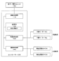
- the block diagram which shows the electrical constitution with which the component mounting machine of FIG. 1 is provided.
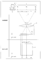
- the figure which shows typically an example of a structure of the recognition camera with which the component mounting machine of FIG. 1 is provided.
- the flowchart which shows an example of scanning imaging.
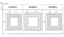
- the figure which shows typically the image of the components C acquired by the scanning imaging of FIG. The flowchart which shows the 1st example of component mounting.
- the flowchart which shows the 2nd example of component mounting.
- the flowchart which shows an example of scanning imaging.
- FIG. 1 is a partial plan view schematically showing a component mounter according to the present invention.
- FIG. 2 is a block diagram showing an electrical configuration of the component mounter of FIG.
- an XYZ orthogonal coordinate system composed of an X direction, a Y direction, and a Z direction orthogonal to each other is shown as appropriate.
- the X direction and the Y direction are horizontal directions
- the Z direction is a vertical direction.
- the component mounter 1 includes a controller 100 that controls the entire apparatus.
- the controller 100 is a computer having an arithmetic processing unit 110, which is a processor composed of a CPU (Central Processing Unit) and a RAM (Random Access Memory), and a storage unit 120 composed of an HDD (Hard Disk Drive). Further, the controller 100 includes a drive control unit 130 that controls the drive system of the component mounter 1 and an imaging control unit 140 that controls the imaging system of the component mounter 1.
- the storage unit 120 stores component information I indicating information about a component such as a package type, and the arithmetic processing unit 110 controls the drive control unit 130 and the imaging control unit 140 while referring to the component information I. Execute component mounting. At this time, the arithmetic processing unit 110 controls component mounting based on the image captured by the imaging control unit 140 by the recognition camera 5. Further, the component mounter 1 is provided with a display / operation unit 150, and the arithmetic processing unit 110 displays the status of the component mounter 1 on the display / operation unit 150, or inputs it to the display / operation unit 150. Or accepting instructions from a designated worker.
- the component mounter 1 includes a pair of conveyors 12 and 12 provided on a base 11. And the component mounting machine 1 mounts components on the board
- the completed board B is carried out from the mounting processing position to the downstream side in the X direction by the conveyor 12.
- the component mounter 1 includes a pair of Y-axis rails 21 and 21 extending in the Y direction, a Y-axis ball screw 22 extending in the Y direction, and a Y-axis motor My (servo motor) that rotationally drives the Y-axis ball screw 22.
- the X-axis rail 23 is fixed to the nut of the Y-axis ball screw 22 while being supported by the pair of Y-axis rails 21 and 21 so as to be movable in the Y direction.
- An X-axis ball screw 24 extending in the X direction and an X-axis motor Mx (servo motor) that rotationally drives the X-axis ball screw 24 are attached to the X-axis rail 23, and the head unit 20 is attached to the X-axis rail 23.
- the nut is fixed to the nut of the X-axis ball screw 24 while being supported so as to be movable in the direction. Therefore, the drive control unit 130 rotates the Y-axis ball screw 22 by the Y-axis motor My to move the head unit 20 in the Y direction, or rotates the X-axis ball screw 24 by the X-axis motor Mx to move the head unit 20 to X. Can be moved in the direction.
- the two component supply units 3 are arranged in the X direction on each side of the pair of conveyors 12 and 12 in the Y direction.
- a plurality of tape feeders 31 are detachably mounted side by side in the X direction on each component supply unit 3.
- the tape feeder 31 extends in the Y direction, and has a component supply location 32 at the tip on the head unit 20 side in the Y direction.
- a tape containing small piece parts such as an integrated circuit, a transistor, and a capacitor at predetermined intervals is loaded in the tape feeder 31.
- Each tape feeder 31 intermittently feeds the tape toward the head unit 20 in the Y direction. As a result, the components in the tape are sent out in the Y direction (feed direction), and are sequentially supplied to the component supply locations 32 of each tape feeder 31.
- the head unit 20 has a plurality of mounting heads 4 arranged in a line at an equal pitch in the X direction.
- a nozzle 41 is detachably attached to the lower end of the mounting head 4, and the mounting head 4 sucks and mounts components by the nozzle 41. That is, the mounting head 4 moves the nozzle 41 above the component supply location 32 of the tape feeder 31, and sucks (picks up) the component supplied to the component supply location 32 by the nozzle 41.
- the mounting head 4 moves above the substrate B at the mounting processing position and mounts the component on the substrate B while holding the component on the nozzle 41.
- the component mounting machine 1 includes a recognition camera 5 mounted on the base 11 facing upward between two component supply units 3 arranged in the X direction.
- the mounting head 4 that has picked up the component from the component supply unit 3 moves above the recognition camera 5 that is the closest of the recognition cameras 5 and passes the component above the recognition camera 5.
- the recognition camera 5 captures an image of a part passing above from below.
- the arithmetic processing unit 110 determines the state of the component attracted by the nozzle 41 based on the imaging result of the recognition camera 5 obtained via the imaging control unit 140.
- FIG. 3 is a diagram schematically showing an example of the configuration of the recognition camera provided in the component mounter of FIG.
- an overall schematic view and a partial plan view are shown.
- a component C adsorbed by the nozzle 41 of the mounting head 4 is also shown.
- the recognition camera 5 includes an image sensor 51 and a lens 52, and images the field F by imaging light from the field F on the image sensor 51 by the lens 52.
- the image sensor 51 is an area sensor composed of a CMOS (Complementary MOS) image sensor.
- the lens 52 is a macro lens having non-telecentricity on the object side, and has an optical axis O parallel to the Z direction.
- a region of interest that is, ROI (Region of Interest) can be set for the image sensor 51 which is an area sensor.
- ROI Region of Interest
- three regions of interest Ac, Aa, Ab are set in this order in the X direction with respect to the image sensor 51.
- Each of the regions of interest Aa, Ab, and Ac is a linear region having a width of one pixel in the X direction, which is composed of a plurality of pixels arranged in a line parallel to the Y direction.
- the region of interest Aa is provided so as to intersect the optical axis O of the lens 52, and the regions of interest Ab and Ac are provided across the optical axis O of the lens 52.
- the distance Lab between the optical axis O of the lens 52 and the region of interest Ab is equal to the distance Lac between the optical axis O of the lens 52 and the region of interest Ac.
- each of the imaging ranges Ra, Rb, and Rc in the field of view F is imaged by the lens 52 onto the regions of interest Aa, Ab, and Ac. That is, by setting the regions of interest Aa, Ab, and Ac, the imaging ranges Ra, Rb, and Rc corresponding to the regions of interest Aa, Ab, and Ac in the visual field F can be selectively imaged.
- Each of the imaging ranges Ra, Rb, and Rc extends in a straight line parallel to the Y direction, and has a width obtained by dividing the width of one pixel of the imaging element 51 by the magnification of the lens 52 in the X direction.
- the imaging range Ra is provided so as to intersect the optical axis O of the lens 52, and the imaging ranges Rb and Rc are provided with the optical axis O of the lens 52 interposed therebetween.
- the distance Lrb between the optical axis O of the lens 52 and the imaging range Rb is equal to the distance Lrc between the optical axis O of the lens 52 and the imaging range Rc.
- the one-dimensional image is an image picked up by a linear region that is composed of a plurality of pixels arranged in a row and has a width of one pixel, in other words, an image for one line of the sensor. .
- the controller 100 acquires the image of the component C by scanning imaging that causes the imaging control unit 140 to perform imaging by the recognition camera 5 while causing the drive control unit 130 to scan the component C by the X-axis motor Mx.
- the component C that is the object of scanning imaging has a BGA (Ball grid) type package in which a plurality of terminals Ct are arranged in a grid pattern on the bottom surface.
- FIG. 4 is a flowchart showing an example of scanning imaging
- FIG. 5 is a diagram schematically showing an image of the component C acquired by the scanning imaging of FIG. 4 is executed under the control of the controller 100.
- the X-axis motor Mx starts component scanning for sequentially passing the component C through the imaging ranges Rb, Ra, and Rc by translating the component C attracted by the nozzle 41 of the mounting head 4 in the X direction. .
- the region of interest Ab of the image sensor 51 repeatedly captures the part C passing through the imaging range Rb at the exposure interval T (step S103).
- the exposure interval T is a time obtained by dividing the width of the imaging range Rb in the X direction by the moving speed V of the part C.
- the moving speed V of the part C is determined based on the output of the encoder of the X-axis motor Mx. .
- step S105 When the part C reaches the imaging range Ra (step S105), the region of interest Aa of the image sensor 51 repeatedly captures the part C passing through the imaging range Ra at the exposure interval T (step S106).
- step S106 By executing step S106 over a period in which the component C passes the imaging range Ra, a two-dimensional component image Ga obtained by imaging the bottom surface of the component C from the direction of the optical axis O is acquired (step S107).
- step S108 When the component C reaches the imaging range Rc (step S108), the region of interest Ac of the image sensor 51 repeatedly captures the component C passing through the imaging range Rc at the exposure interval T (step S109).
- step S109 By executing step S109 over a period in which the part C passes the imaging range Rc, a two-dimensional part image Gc obtained by imaging the bottom surface of the part C from an oblique direction that forms an angle ⁇ c with the optical axis O is acquired. (Step S110).
- FIG. 6 is a flowchart showing a first example of component mounting.
- the flowchart in FIG. 6 is executed under the control of the controller 100.
- step S ⁇ b> 201 the mounting head 4 sucks the component C supplied from the component supply unit 3 to each of the plurality of nozzles 41. Subsequently, the mounting head 4 moves from the component supply unit 3 toward the recognition camera 5 and executes scanning imaging for each component C (step S202). As a result, three component images Ga, Gb, and Gc are acquired for each of the plurality of components C attracted by the mounting head 4.
- step S203 the controller 100 performs stereo matching on the two component images Gb and Gc of each component C using the arithmetic processing unit 110, thereby acquiring three-dimensional information that is information regarding the three-dimensional shape of each component C. To do. Specifically, the position of the vertex of each terminal Ct of the component C is acquired as the three-dimensional information of the component C. Then, the controller 100 determines the quality of each component C by measuring the coplanarity of the terminal Ct of each component C based on this three-dimensional information (step S204). In step S205, the controller 100 measures the position of the component C by calculating the position of the component C with respect to the nozzle 41 by the arithmetic processing unit 110 based on the component image Ga of each component C.
- step S206 the mounting head 4 moves above the substrate B and mounts the component C attracted by each nozzle 41 on the substrate B (step S206).
- step S204 only the component C determined to be non-defective is mounted on the substrate B, and the component C determined to be defective is discarded later.
- the position where the component C is mounted on the substrate B is controlled by adjusting the position of the nozzle 41 based on the position of the component C with respect to the nozzle 41 measured in step S205.
- Step S207 when the mounting turn (steps S201 to S206) in which the mounting head 4 sucks the component C from the component supply unit 3 and mounts it on the substrate B is completed, it is determined whether all the components C have been mounted on the substrate B. (Step S207). If the mounting of all components C has not been completed (in the case of “NO” in step S207), the mounting turns in steps S201 to S206 are repeated. On the other hand, when the mounting of all the components C is completed (in the case of “YES” in step S207), the component mounting in FIG. 6 ends.
- the component C is passed through each of the imaging range Rb and the imaging range Rc aligned in the X direction while relatively moving the component C in the X direction.
- Each of the imaging range Rb and the imaging range Rc extends linearly in the Y direction, and the recognition camera 5 forms an image of light from the imaging range Rb and the imaging range Rc on the imaging element 51 by the lens 52.
- the one-dimensional images of the imaging range Rb and the imaging range Rc can be taken. Therefore, a part image Gb which is a two-dimensional image of the part C is acquired by causing the recognition camera 5 to repeatedly capture the imaging range Rb as the part C passes through the imaging range Rb, and the part C passes through the imaging range Rc.
- the part image Gc that is a two-dimensional image of the part C can be acquired by causing the recognition camera 5 to repeatedly capture the imaging range Rc.
- the part image Gb and the part image Gc correspond to two images of the part C viewed from different angles. Based on the image Gc, the three-dimensional information of the part C can be obtained. In this way, two component images Gb and Gc obtained by viewing the component C from different angles can be captured by the single recognition camera 5 to obtain the three-dimensional information of the component C. As a result, it is possible to suppress an increase in cost.
- the high-accuracy component C can be obtained without requiring a correction operation to cope with the difference in optical characteristics of the plurality of cameras as described above. 3D information can be acquired. In this way, it is possible to easily obtain highly accurate three-dimensional information of a component while suppressing an increase in cost.
- the technique of obtaining a two-dimensional image by repeatedly capturing one-dimensional images of the imaging ranges Rb and Rc through which the component C passes in this way captures the component C in the field of view F at one time without setting an ROI.
- the component image Gc is formed by arranging the one-dimensional images extending in the Y direction captured in the same imaging ranges Rb and Rc in the X direction, the component images Gb and Gc are distorted. Therefore, no tilt correction is required.
- a configuration different from the above is conceivable when two images obtained by capturing parts from different angles are acquired by one camera.
- a two-dimensional imaging range in which the part C can be included is provided at a position off the optical axis O, the part C is imaged once in the imaging range, and further rotated 180 ° about the vertical center.
- the part C may be imaged once in the imaging range.
- this configuration requires not only correction as described above, but also the accuracy of the mechanism for rotating the nozzles may affect the image of the component C.
- the above embodiment has an advantage that such influence can be eliminated.
- the distance Lrb between the optical axis O of the lens 52 and the imaging range Rb is equal to the distance Lrc between the optical axis O of the lens 52 and the imaging range Rc.
- the component image Gb and the component image Gc having the same width W (FIG. 5) in the Y direction can be captured. Therefore, when obtaining the three-dimensional information of the component C, the calculation for matching the width W of these component images Gb and Gc can be omitted.
- the controller 100 measures the coplanarity of the plurality of terminals Ct included in the component C based on the three-dimensional shape. This makes it possible to measure the coplanarity of the terminal Ct of the component C with high accuracy while suppressing an increase in cost.
- the recognition camera 5 forms an image on the image sensor 51 by using the lens 52 with the light from the imaging range Ra linearly extending in the Y direction between the imaging range Rb and the imaging range Rc. A one-dimensional image of Ra is captured.
- the X-axis motor Mx moves the component C in the X direction with respect to the recognition camera 5, thereby executing component scanning that sequentially passes the component C through the imaging range Rb, the imaging range Ra, and the imaging range Rc.
- the controller 100 acquires the component image Ga of the component C by causing the recognition camera 5 to repeatedly capture the imaging range Ra as the component C passes through the imaging range Ra, and determines the positional relationship between the nozzle 41 and the component C. Measurement is performed based on the component image Ga.
- the measurement of the coplanarity of the terminal Ct of the component C and the measurement of the positional relationship between the nozzle 41 and the component C can be performed by the single recognition camera 5, and the increase in cost can be effectively suppressed. It becomes possible.
- the recognition camera 5 includes an area sensor as the image sensor 51, and linear areas where light from each of the imaging ranges Ra, Rb, and Rc is imaged are areas of interest Aa, Ab, and Ac of the area sensor. By selecting, one-dimensional images of the imaging ranges Ra, Rb, and Rc are taken. In other words, by using the region of interest setting function of the area sensor, each measurement in steps S204 and S205 can be performed by one recognition camera 5, and the coplanarity of the terminal Ct of the component C is highly accurate while suppressing cost increase. It becomes possible to measure.
- FIG. 7 is a flowchart showing a second example of component mounting.
- the flowchart in FIG. 7 is executed under the control of the controller 100.
- differences from the above-described embodiment will be mainly described, and common points will be denoted by corresponding reference numerals, and description thereof will be omitted as appropriate.
- the same effect can be achieved by providing a common configuration.
- the part information I includes information indicating whether or not coplanarity measurement is necessary according to the type of the part C.
- the component information I stipulates that measurement of coplanarity is required for a component C having a package such as BGA or QFP (Quad Flat Package), whereas a chip capacitor, chip resistance, etc. It is stipulated that the measurement of coplanarity is unnecessary for the part C.
- steps S202 to S206 are executed in the same manner as described above, and the component C is mounted on the board B.
- the X-axis motor Mx and the Y-axis motor My drive the mounting head 4 to each nozzle 41.
- the part C to be picked up is moved directly above the recognition camera 5 and placed in the field of view F of the recognition camera 5 (step S302). Specifically, the part C is placed in the field of view F by passing the part C through the field of view F through the part C on the way from the component supply unit 3 to the upper side of the substrate B.
- the recognition camera 5 captures the field of view F without setting the region of interest of the image sensor 51, thereby executing area imaging for capturing the two-dimensional component image Gf of each component C once (see FIG. Step S303).
- step S304 the controller 100 measures the position of the component C by calculating the position of the component C with respect to the nozzle 41 by the arithmetic processing unit 110 based on the component image Gf of each component C. Then, the mounting head 4 moves above the board B and mounts the component C attracted by each nozzle 41 on the board B (step S305). At this time, the position where the component C is mounted on the substrate B is controlled by adjusting the position of the nozzle 41 based on the position of the component C with respect to the nozzle 41 measured in step S304.
- step S207 it is determined whether or not the mounting of all components C on the board B is completed. If the mounting of all the parts C is not completed (“NO” in step S207), the process returns to step S201 and the mounting turn is repeated. On the other hand, when the mounting of all the components C is completed (in the case of “YES” in step S207), the component mounting in FIG. 7 ends.
- the recognition camera 5 can capture a two-dimensional image of the field of view F by forming the light from the field of view F including the component C on the image sensor 51 by the lens 52.
- the controller 100 can selectively execute the first mode including steps S201, S301, and S202 to S206 and the second mode including steps S201 and S301 to S305.
- the first mode is a mode in which component images Ga, Gb, and Gc are acquired while causing the X-axis motor Mx to perform component scanning, and the positional relationship between the coplanarity and the nozzle 41 and the component C is measured.
- the component C is captured by the recognition camera 5 while the component C is placed in the field of view F by the X-axis motor Mx and the Y-axis motor My, and the component image Gf of the component C is acquired.
- This is a second mode in which the positional relationship with the part C is measured based on the part image Gf.
- both the measurement of the coplanarity and the measurement of the positional relationship between the nozzle 41 and the part C are required, both measurements can be accurately executed by executing the first mode.
- the measurement can be accurately performed by executing the second mode.
- the storage unit 120 stores part information I that defines the necessity of measuring the coplanarity according to the type of the part C. Then, the controller 100 executes the first mode if there is a component C that requires measurement of coplanarity in the component C attracted by the mounting head 4 in the mounting turn. Thereby, the measurement of the coplanarity and the measurement of the positional relationship between the nozzle 41 and the part C can be accurately executed. Further, in the mounting turn, the second mode is executed if there is no component C that needs to be measured for coplanarity in the component C sucked by the mounting head 4. Thereby, the measurement of the positional relationship between the nozzle 41 and the component C can be accurately performed.
- the time required for component scanning can be omitted, and the mounting turn can be executed promptly.
- the embodiment according to the component mounter 1 corresponds to the first aspect of the present invention.
- the component mounter 1 corresponds to an example of the “component mounter” of the present invention
- the head unit 20 corresponds to an example of the “mounting unit” of the present invention
- the component C corresponds to an example of the “component” of the present invention.
- the recognition camera 5 corresponds to an example of the “camera” of the present invention
- the image sensor 51 corresponds to an example of each of the “image sensor” and the “area sensor” of the present invention
- the lens 52 corresponds to the “optical system” of the present invention.
- the optical axis O corresponds to an example of the “optical axis” of the present invention
- the X direction corresponds to an example of the “scanning direction” of the present invention
- the Y direction corresponds to the “extending direction” of the present invention.
- the imaging range Rb corresponds to an example of the “first imaging range” of the present invention
- the imaging range Rc corresponds to an example of the “second imaging range” of the present invention
- the imaging range Ra corresponds to the actual imaging range Ra.
- This corresponds to an example of the “third imaging range” of the invention
- the field of view F corresponds to an example of the “fourth imaging range” of the present invention.
- the component image Gb corresponds to an example of the “first image” of the present invention
- the component image Gc corresponds to an example of the “second image” of the present invention
- the component image Ga corresponds to the “third image” of the present invention.
- the component image Gf corresponds to an example of the “fourth image” of the present invention
- the X-axis motor Mx and the Y-axis motor My function as an example of the “drive unit” of the present invention.
- the controller 100 corresponds to an example of the “controller” of the present invention
- the component supply unit 3 corresponds to an example of the “component supply unit” of the present invention
- the storage unit 120 corresponds to an example of the “storage unit” of the present invention. .
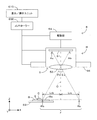
- FIG. 8 is a diagram schematically showing an example of an appearance inspection machine according to the present invention.
- the appearance inspection machine 6 is a solder inspection apparatus that determines the quality of the solder S bonded to the substrate B based on the appearance of the solder S, and includes a controller 600 and a display / operation unit 610.
- the controller 600 is a computer having a processor constituted by a CPU, a RAM, and the like, and an HDD, and controls the inspection of the solder S bonded to the substrate B.
- the display / operation unit 610 is constituted by, for example, a touch panel, and the user can set the inspection condition of the solder S and confirm the inspection result of the solder S via the display / operation unit 610.
- the appearance inspection machine 6 includes a substrate transport unit 62 that transports the substrate B, an inspection head H that faces the substrate B from above, and a drive unit 64 that drives the inspection head H.
- the substrate transport unit 62 is composed of, for example, a pair of conveyors, and fixes the substrate B loaded from the outside to a predetermined holding position (the position of the substrate B in FIG. 8), or unloads the substrate B from the holding position to the outside. To do.
- the component C is joined to the surface Bs of the substrate B by the solder S, and the substrate transport unit 62 fixes the substrate B at the holding position while holding the surface Bs of the substrate B horizontally.
- the drive unit 64 is configured by, for example, an XY robot, and drives the inspection head H two-dimensionally in the horizontal direction so that the inspection head H is opposed to a predetermined inspection position of the substrate B held at the holding position.
- the inspection head H includes a recognition camera 5 and an illumination 66 provided around the recognition camera 5.
- the recognition camera 5 is held toward the board B below. Then, the recognition camera 5 selectively captures one-dimensional images in the imaging ranges Rb and Rc in the field of view F.
- the illumination 66 has an annular shape centered on the optical axis O, and irradiates light onto the field of view F of the recognition camera 5. Then, the appearance inspection machine 6 performs scanning imaging on the solder S that joins the component C to the surface Bs of the substrate B.
- FIG. 9 is a flowchart showing an example of scanning imaging. 9 is executed under the control of the controller 600.
- the drive unit 64 starts solder scanning for sequentially passing the solder S through the imaging ranges Rb and Rc by translating the inspection head H in the X direction (opposite the arrow in the drawing).
- step S403 When the solder S reaches the imaging range Rb (step S402), the region of interest Ab of the image sensor 51 repeatedly images the solder S passing through the imaging range Rb at the exposure interval T (step S403).
- step S403 By executing step S403 over a period in which the solder S passes through the imaging range Rb, a two-dimensional solder image Gsb obtained by imaging the solder S from an oblique direction that forms an angle ⁇ b with the optical axis O is acquired. (Step S404).
- step S406 When the solder S reaches the imaging range Rc (step S405), the region of interest Ac of the image sensor 51 repeatedly images the solder S passing through the imaging range Rc at the exposure interval T (step S406).
- step S406 By executing step S406 over a period in which the solder S passes through the imaging range Rc, a two-dimensional solder image Gsc obtained by imaging the solder S from an oblique direction that forms an angle ⁇ c with the optical axis O is acquired. (Step S407).
- the scanning imaging of FIG. 8 ends.
- the controller 600 acquires the three-dimensional information which is the information regarding the three-dimensional shape of the solder S by performing stereo matching with respect to the solder images Gsb and Gsc obtained by scanning imaging. Specifically, the distance (height) between the surface of the solder S and the substrate B is acquired as three-dimensional information of the solder S. Then, the controller 600 determines the quality of the solder S by inspecting the fillet of the solder S based on the three-dimensional information.
- the solder S is passed through each of the imaging range Rb and the imaging range Rc aligned in the X direction while relatively moving the solder S in the X direction.
- Each of the imaging range Ra and the imaging range Rb extends linearly in the Y direction, and the recognition camera 5 forms an image of light from the imaging range Rb and the imaging range Rc on the imaging element 51 by the lens 52.
- the recognition camera 5 forms an image of light from the imaging range Rb and the imaging range Rc on the imaging element 51 by the lens 52.
- the recognition camera 5 by causing the recognition camera 5 to repeatedly capture the imaging range Rb as the solder S passes through the imaging range Rb, a solder image Gsb that is a two-dimensional image of the solder S is obtained, and the solder S passes through the imaging range Rc.
- the recognition camera 5 repeatedly captures the imaging range Rc, whereby a solder image Gsc that is a two-dimensional image of the solder S can be acquired.
- these solder images Gsb and Gsc correspond to two images of the solder S viewed from different angles, and the solder images Gsb and Gsc The three-dimensional information of the solder S can be obtained based on the above.
- the two solder images Gsb and Gsc obtained by viewing the solder S from different angles can be imaged by the single recognition camera 5 to obtain the three-dimensional information of the solder S.
- the solder images Gsb and Gsc are acquired by the same lens 52, the three-dimensional solder S can be obtained with high accuracy without requiring a correction operation for dealing with the difference in optical characteristics of the plurality of cameras as described above.
- the shape can be acquired. In this way, it is possible to easily obtain highly accurate three-dimensional information of the solder S while suppressing an increase in cost.
- the embodiment according to the appearance inspection machine 6 corresponds to the second aspect of the present invention.
- the appearance inspection machine 6 corresponds to an example of the “appearance inspection machine” of the present invention
- the substrate transport unit 62 corresponds to an example of the “substrate holding unit” of the present invention
- the substrate B corresponds to an example of the “substrate” of the present invention.
- the component C corresponds to an example of the “component” of the present invention
- the solder S corresponds to an example of the “solder” of the present invention
- the recognition camera 5 corresponds to an example of the “camera” of the present invention
- the imaging element 51 corresponds to an example of the “imaging element” of the present invention
- the lens 52 corresponds to an example of the “lens” of the present invention
- the X direction corresponds to an example of the “scanning direction” of the present invention
- the Y direction corresponds to an example of the “extending direction” of the present invention
- the imaging range Rb corresponds to an example of the “first imaging range” of the present invention
- the imaging range Rc corresponds to an example of the “second imaging range” of the present invention.
- the drive unit 64 corresponds to an example of the “drive unit” of the present invention
- the controller 600 corresponds to the “controller” of the present invention.
- the solder image Gsb corresponds to an example of the "first image” in the present invention
- a solder image Gsc corresponds to an example of the "second image” in the present invention.
- the present invention is not limited to the above embodiment, and various modifications can be made to the above without departing from the spirit of the present invention.
- the component C is moved relative to the recognition camera 5 by driving the head unit 20.
- the component C may be moved relative to the recognition camera 5 by driving the recognition camera 5 mounted on the head unit 20.
- the arrangement of the imaging ranges Rb and Rc is not limited to the example of FIG. Therefore, the distance Lrb between the optical axis O of the lens 52 and the imaging range Rb and the distance Lrc between the optical axis O of the lens 52 and the imaging range Rc may be different. Alternatively, one of the imaging ranges Rb and Rc may be arranged so as to intersect the optical axis O of the lens 52. Even in this case, the three-dimensional information of the component C can be obtained by performing stereo matching on the component images Gb and Gc.
- a camera for measuring the position of the component C with respect to the nozzle 41 is provided separately from the recognition camera 5, and only the imaging of the component images Gb and Gc for acquiring the three-dimensional information of the component C is performed on the recognition camera 5. You may let them. In this case, steps S105 to S107 may be omitted in the scanning imaging of FIG.
- the use of the three-dimensional information of the part C is not limited to the above-described measurement of coplanarity.
- the three-dimensional information of the part C may be used to determine the inclination of the part C attracted by the nozzle 41.
- the arrangement of the nozzles 41 in the head unit 20 is not limited to a linear shape as described above. Therefore, as shown in Japanese Patent Application Laid-Open No. 2012-054384, a rotary head in which nozzles 41 are arranged circumferentially may be mounted on the head unit 20. Alternatively, a single nozzle 41 may be attached to the head unit 20.
- the solder S is moved relative to the recognition camera 5 by driving the inspection head H.
- the solder S may be moved relative to the recognition camera 5 by driving the substrate B by the substrate transport unit 62.
- the arrangement of the imaging ranges Rb and Rc is not limited to the example of FIG. Therefore, the distance Lrb between the optical axis O of the lens 52 and the imaging range Rb and the distance Lrc between the optical axis O of the lens 52 and the imaging range Rc may be different. Alternatively, one of the imaging ranges Rb and Rc may be arranged so as to intersect the optical axis O of the lens 52. Even in this case, stereo matching can be performed on the solder images Gsb and Gsc, and the three-dimensional information of the solder S can be obtained.
- the image sensor 51 is constituted by a CMOS image sensor.
- the image sensor 51 may be constituted by another solid-state image sensor such as a CCD (Charge-Coupled Device) image sensor.
- the component mounter 1 and the appearance inspection machine 6 capture one-dimensional images of the imaging ranges Rb and Rc by setting the regions of interest Ab and Ac for the area sensor.
- a one-dimensional image of each of the imaging ranges Rb and Rc may be selectively captured by arranging a line sensor at a position corresponding to the regions of interest Ab and Ac.
- a one-dimensional image may be captured by the line sensor.
- the scanning direction of the component C or the solder S and the extending direction of the imaging ranges Rb and Rc are not limited to the above examples. Therefore, for example, it is not always necessary that the scanning direction and the extending direction are orthogonal to each other.
- SYMBOLS 1 ... Component mounting machine, 20 ... Head unit (mounting unit), 3 ... Component supply part, 5 ... Recognition camera (camera), 51 ... Image sensor (area sensor), 52 ... Lens (optical system), 100 ... Controller, 120 ... Storage unit, Mx ... X-axis motor (drive unit), My ... Y-axis motor (drive unit)) C ... Parts, F ... Field of view (fourth imaging range), Ra ... Imaging range (third imaging range), Rb ... Imaging range (first imaging range), Rc ... Imaging range (second imaging range), Gb ... Component image (first image), Gc ... Component image (second image), Ga ... Component image (third image) ), O ...
- optical axis X ... X direction (scanning direction), Y ... Y direction (extending direction), S201, S301, S202 to S206 ... first mode, S201, S301 to S305 ... second mode, S201 ... S206 ... Mounting turn, S201, 301, S202 to S206 ... Mounting turn, S201, S301 to S305 ... Mounting turn, 6 ... Appearance inspection machine, 62 ... Substrate transport unit (substrate holding unit), 64 ... Drive unit, 600 ... Controller, Gsb ... Solder image (No. 1) 1 image), Gsc ... solder image (second image), S ... solder
Landscapes
- Engineering & Computer Science (AREA)
- Physics & Mathematics (AREA)
- General Physics & Mathematics (AREA)
- Theoretical Computer Science (AREA)
- Operations Research (AREA)
- Manufacturing & Machinery (AREA)
- Microelectronics & Electronic Packaging (AREA)
- Supply And Installment Of Electrical Components (AREA)
- Length Measuring Devices By Optical Means (AREA)
- Image Input (AREA)
Abstract
認識カメラ5に対して部品C(半田S)を移動させながら、認識カメラ5が、撮像範囲Rb、Rcからの光をレンズ52により撮像素子51に結像することで、撮像範囲Rb、Rcそれぞれの一次元画像を繰り返し撮像して、部品C(半田S)の二次元画像を撮像する。しかも、認識カメラ5のレンズ52は物体側に非テレセントリック性を有するため、これらの二次元画像に基づき部品C(半田S)の三次元情報を求めることができる。こうして、異なる角度から見た2枚の画像を1台の認識カメラ5で撮像して、部品C(半田S)の三次元情報を求めることができる。その結果、コストアップを抑えつつ高精度な部品C(半田S)の三次元情報を簡便に取得することが可能となっている。
Description
この発明は、部品あるいは部品を基板に接合する半田の三次元情報を求める技術に関する。
電子基板の生産プロセスでは、フィーダーから供給された部品を実装ヘッドにより基板に実装する部品実装機や、基板へ部品を接合する半田の良否を検査する外観検査機等が一般に用いられる。また、このような生産プロセスにおいては、部品あるいは半田の三次元情報が適宜求められる。例えば部品実装機では、部品が有する複数の端子のコプラナリティを測定するために、部品の三次元情報が求められる。あるいは、外観検査機では、半田のフィレットを確認するために、半田の三次元情報が求められる。
これに対して、特許文献1では、部品の三次元情報を取得する構成を備えた部品実装機が示されている。この部品実装機では、それぞれ異なる角度から部品を撮像する複数のカメラが設けられ、各カメラが撮像した部品の画像に対してステレオマッチングを実行することで部品の三次元情報が求められる。
しかしながら、特許文献1の構成によると、複数のカメラを装備する必要がある。かかる構成により部品あるいは半田の三次元情報を取得した場合、各カメラの光学特性の差が三次元情報の精度に影響するため、光学特性の差を補正するための演算が適宜必要になる。また、カメラの台数に応じて装置のコストも高くなる。
この発明は上記課題に鑑みなされたものであり、コストアップを抑えつつ、高精度な部品の三次元情報を簡便に取得可能とする技術の提供を第1目的とするとともに、コストアップを抑えつつ、高精度な半田の三次元情報を簡便に取得可能とする技術の適用を第2目的とする。
本発明の第1態様に係る部品実装機は、部品を保持する実装ユニットと、それぞれ走査方向に交差する延設方向に直線状に延設されて走査方向に並ぶ第1撮像範囲および第2撮像範囲からの光を、部品側に非テレセントリック性を有する光学系により撮像素子に結像することで、第1撮像範囲および第2撮像範囲それぞれの一次元画像を撮像するカメラと、カメラに対して相対的に部品を走査方向に移動させることで、第1撮像範囲および第2撮像範囲に順に部品を通過させる駆動部と、部品の第1撮像範囲の通過に伴ってカメラに第1撮像範囲を繰り返し撮像させることで部品の第1画像を取得し、部品の第2撮像範囲の通過に伴ってカメラに第2撮像範囲を繰り返し撮像させることで部品の第2画像を取得し、第1画像および第2画像から部品の三次元情報を求めるコントローラーとを備える。
本発明の第1態様に係る部品認識方法は、カメラに対する部品の走査方向への相対的な移動を開始する工程と、それぞれ走査方向に交差する延設方向に直線状に延設されて走査方向に並ぶ第1撮像範囲および第2撮像範囲からの光を、部品側に非テレセントリック性を有する光学系により撮像素子に結像することで、第1撮像範囲および第2撮像範囲それぞれの一次元画像を撮像するカメラを用いて部品を撮像する工程とを備え、部品の第1撮像範囲の通過に伴ってカメラに第1撮像範囲を繰り返し撮像させることで部品の第1画像を取得し、部品の第2撮像範囲の通過に伴ってカメラに第2撮像範囲を繰り返し撮像させることで部品の第2画像を取得し、第1画像および第2画像から部品の三次元情報を求める。
このように構成された本発明の第1態様(部品実装機、部品認識方法)は、走査方向に部品を相対移動させながら、走査方向に並ぶ第1撮像範囲および第2撮像範囲のそれぞれに部品を通過させる。第1撮像範囲および第2撮像範囲のそれぞれは、走査方向に交差する延設方向に直線状に延設されており、カメラは、第1撮像範囲および第2撮像範囲からの光を光学系により撮像素子に結像することで、第1撮像範囲および第2撮像範囲それぞれの一次元画像を撮像可能である。したがって、部品の第1撮像範囲の通過に伴ってカメラに第1撮像範囲を繰り返し撮像させることで部品の二次元画像である第1画像を取得し、部品の第2撮像範囲の通過に伴ってカメラに第2撮像範囲を繰り返し撮像させることで部品の二次元画像である第2画像を取得することができる。しかも、カメラの光学系は部品側に非テレセントリック性を有するため、第1画像および第2画像は、異なる角度から部品を見た2枚の画像に相当し、第1画像および第2画像に基づき部品の三次元情報を求めることができる。こうして本発明では、異なる角度から部品を見た第1画像および第2画像を1台のカメラで撮像して、部品の三次元情報を求めることができる。その結果、コストアップを抑えることが可能となっている。しかも、第1画像および第2画像を同一の光学系により取得しているため、上述のような複数のカメラの光学特性の差に対応するための補正演算を要することなく高精度な部品の三次元情報を取得できる。こうして、コストアップを抑えつつ、高精度な部品の三次元情報を簡便に取得することが可能となっている。
また、走査方向において、光学系の光軸と第1撮像範囲との距離と、光軸と第2撮像範囲との距離とが等しいように、部品実装機を構成しても良い。これによって、延設方向に同じ幅を有する第1画像および第2画像を撮像することができる。そのため、部品の三次元情報を求める際に、これらの画像の幅を合わせるための演算を省略することができる。
また、コントローラーは、部品が有する複数の端子のコプラナリティを三次元形状に基づき測定するように、部品実装機を構成しても良い。これによって、コストアップを抑えつつ、部品の端子のコプラナリティを高精度に測定することが可能となる。
また、カメラは、第1撮像範囲と第2撮像範囲との間で延設方向に直線状に延設された第3撮像範囲からの光を光学系により撮像素子に結像することで、第3撮像範囲の一次元画像を撮像し、駆動部は、カメラに対して相対的に部品を走査方向に移動させることで、第1撮像範囲、第3撮像範囲および第2撮像範囲に順に部品を通過させる部品走査を実行し、コントローラーは、部品の第3撮像範囲の通過に伴ってカメラに第3撮像範囲を繰り返し撮像させることで部品の第3画像を取得し、実装ユニットと部品との位置関係を第3画像に基づき測定するように、部品実装機を構成しても良い。かかる構成では、部品の端子のコプラナリティの測定と、実装ユニットと部品との位置関係の測定とを1台のカメラで実行することができ、コストアップの抑制を効果的に図ることが可能となる。
また、カメラは、撮像素子としてエリアセンサーを有し、第1撮像範囲、第2撮像範囲および第3撮像範囲のそれぞれからの光が結像される直線状の領域をエリアセンサーの関心領域に選択することで、第1撮像範囲、第2撮像範囲および第3撮像範囲それぞれの一次元画像を撮像するように、部品実装機を構成しても良い。つまり、エリアセンサーが有する関心領域の設定機能を用いることで、各測定を1台のカメラで実行でき、コストアップを抑えつつ、部品の端子のコプラナリティを高精度に測定することが可能となる。
また、カメラは、部品を包括可能な第4撮像範囲からの光を光学系により撮像素子に結像することで、第4撮像範囲の二次元画像を撮像し、コントローラーは、駆動部に部品走査を実行させつつ第1画像、第2画像および第3画像を取得して、コプラナリティおよび実装ユニットと部品との位置関係を測定する第1モードと、駆動部により部品を第4撮像範囲に収めつつカメラに第4撮像範囲を撮像させることで部品の第4画像を取得して、実装ユニットと部品との位置関係を第4画像に基づき測定する第2モードとを選択的に実行するように、部品実装機を構成しても良い。かかる構成では、コプラナリティの測定および実装ユニットと部品との位置関係の測定の両測定が必要な場合は、第1モードを実行することで、両測定を的確に実行できる。また、両測定のうち実装ユニットと部品との位置関係の測定のみが必要な場合には、第2モードを実行することで当該測定を的確に実行できる。しかも、第2モードでは、部品を第4撮像範囲に収めれば足り、第1撮像範囲から第2撮像範囲へ走査方向に部品を走査する部品走査を実行する必要が無い。そのため、部品走査に要する時間を省略でき、基板への部品の実装を速やかに実行可能となる。
また、部品を供給する部品供給部と、部品の種類に応じてコプラナリティの測定の要否を記憶する記憶部とをさらに備え、実装ユニットは、部品供給部から部品を吸着して基板に実装する実装ターンを繰り返し実行し、コントローラーは、実装ターンにおいて、実装ユニットにより吸着された部品にコプラナリティの測定が必要な部品が存在すれば第1モードを実行し、実装ユニットにより吸着された部品にコプラナリティの測定が必要な部品が存在しなければ第2モードを実行するように、部品実装機を構成しても良い。かかる構成では、実装ターンにおいて、実装ユニットにより吸着された部品にコプラナリティの測定が必要な部品が存在すれば、第1モードを実行することで、コプラナリティの測定および実装ユニットと部品との位置関係の測定を的確に実行できる。また、実装ターンにおいて、実装ユニットにより吸着された部品にコプラナリティの測定が必要な部品が存在しなければ、第2モードを実行することで、実装ユニットと部品との位置関係の測定を的確に実行できる。しかも、第2モードでは、部品を第4撮像範囲に収めれば足り、第1撮像範囲から第2撮像範囲へ走査方向に部品を走査する部品走査を実行する必要が無い。そのため、部品走査に要する時間を省略でき、実装ターンを速やかに実行可能となる。
本発明の第2態様に係る外観検査機は、半田により部品が接合された基板を保持する基板保持部と、それぞれ走査方向に交差する延設方向に直線状に延設されて走査方向に並ぶ第1撮像範囲および第2撮像範囲からの光を、基板側に非テレセントリック性を有する光学系により撮像素子に結像することで、第1撮像範囲および第2撮像範囲それぞれの一次元画像を撮像するカメラと、カメラに対して相対的に半田を走査方向に移動させることで、第1撮像範囲および第2撮像範囲に順に半田を通過させる駆動部と、半田の第1撮像範囲の通過に伴ってカメラに第1撮像範囲を繰り返し撮像させることで半田の第1画像を取得し、半田の第2撮像範囲の通過に伴ってカメラに第2撮像範囲を繰り返し撮像させることで半田の第2画像を取得し、第1画像および第2画像から半田の三次元情報を求めるコントローラーとを備える。
本発明の第2態様に係る外観検査方法は、基板に部品を接合する半田のカメラに対する走査方向への相対的な移動を開始する工程と、それぞれ走査方向に交差する延設方向に直線状に延設されて走査方向に並ぶ第1撮像範囲および第2撮像範囲からの光を、基板側に非テレセントリック性を有する光学系により撮像素子に結像することで、第1撮像範囲および第2撮像範囲それぞれの一次元画像を撮像するカメラを用いて半田を撮像する工程とを備え、半田の第1撮像範囲の通過に伴ってカメラに第1撮像範囲を繰り返し撮像させることで半田の第1画像を取得し、半田の第2撮像範囲の通過に伴ってカメラに第2撮像範囲を繰り返し撮像させることで半田の第2画像を取得し、第1画像および第2画像から半田の三次元情報を求める。
このように構成された本発明の第2態様(外観検査機、外観検査方法)は、走査方向に半田を相対移動させながら、走査方向に並ぶ第1撮像範囲および第2撮像範囲のそれぞれに半田を通過させる。第1撮像範囲および第2撮像範囲のそれぞれは、走査方向に交差する延設方向に直線状に延設されており、カメラは、第1撮像範囲および第2撮像範囲からの光を光学系により撮像素子に結像することで、第1撮像範囲および第2撮像範囲それぞれの一次元画像を撮像可能である。したがって、半田の第1撮像範囲の通過に伴ってカメラに第1撮像範囲を繰り返し撮像させることで半田の二次元画像である第1画像を取得し、半田の第2撮像範囲の通過に伴ってカメラに第2撮像範囲を繰り返し撮像させることで半田の二次元画像である第2画像を取得することができる。しかも、カメラの光学系は基板側に非テレセントリック性を有するため、第1画像および第2画像は、異なる角度から半田を見た2枚の画像に相当し、第1画像および第2画像に基づき半田の三次元情報を求めることができる。こうして本発明では、異なる角度から半田を見た第1画像および第2画像を1台のカメラで撮像して、半田の三次元情報を求めることができる。その結果、コストアップを抑えることが可能となっている。しかも、第1画像および第2画像を同一の光学系により取得しているため、上述のような複数のカメラの光学特性の差に対応するための補正演算を要することなく高精度な半田の三次元形状を取得できる。こうして、コストアップを抑えつつ、高精度な半田の三次元情報を簡便に取得することが可能となっている。
本発明の第1態様によれば、コストアップを抑えつつ、高精度な部品の三次元情報を簡便に取得することが可能となる。本発明の第2態様によれば、コストアップを抑えつつ、高精度な半田の三次元情報を簡便に取得することが可能となる。
図1は本発明に係る部品実装機を模式的に示す部分平面図である。図2は図1の部品実装機が備える電気的構成を示すブロック図である。図1および以下の図では、互いに直交するX方向、Y方向およびZ方向で構成されるXYZ直交座標系を適宜示す。なお、この座標系において、X方向およびY方向は水平方向であり、Z方向は鉛直方向である。
図2に示すように、部品実装機1は、装置全体を統括的に制御するコントローラー100を備える。コントローラー100は、CPU(Central Processing Unit)やRAM(Random Access Memory)で構成されたプロセッサーである演算処理部110およびHDD(Hard Disk Drive)で構成された記憶部120を有するコンピューターである。さらに、コントローラー100は、部品実装機1の駆動系を制御する駆動制御部130と、部品実装機1の撮像系を制御する撮像制御部140とを有する。
記憶部120には、パッケージタイプ等の部品に関する情報を示す部品情報Iが記憶されており、演算処理部110は部品情報Iを参照しつつ、駆動制御部130および撮像制御部140を制御することで部品実装を実行する。この際、演算処理部110は撮像制御部140が認識カメラ5により撮像した画像に基づき、部品実装を制御する。また、部品実装機1には、表示/操作ユニット150が設けられており、演算処理部110は、部品実装機1の状況を表示/操作ユニット150に表示したり、表示/操作ユニット150に入力された作業者からの指示を受け付けたりする。
図1に示すように、部品実装機1は、基台11の上に設けられた一対のコンベア12、12を備える。そして、部品実装機1は、コンベア12によりX方向(基板搬送方向)の上流側から実装処理位置(図1の基板Bの位置)に搬入した基板Bに対して部品を実装し、部品実装を完了した基板Bをコンベア12により実装処理位置からX方向の下流側へ搬出する。
部品実装機1では、Y方向に延びる一対のY軸レール21、21と、Y方向に延びるY軸ボールネジ22と、Y軸ボールネジ22を回転駆動するY軸モーターMy(サーボモーター)とが設けられ、X軸レール23が一対のY軸レール21、21にY方向に移動可能に支持された状態でY軸ボールネジ22のナットに固定されている。X軸レール23には、X方向に延びるX軸ボールネジ24と、X軸ボールネジ24を回転駆動するX軸モーターMx(サーボモーター)とが取り付けられており、ヘッドユニット20がX軸レール23にX方向に移動可能に支持された状態でX軸ボールネジ24のナットに固定されている。したがって、駆動制御部130は、Y軸モーターMyによりY軸ボールネジ22を回転させてヘッドユニット20をY方向に移動させ、あるいはX軸モーターMxによりX軸ボールネジ24を回転させてヘッドユニット20をX方向に移動させることができる。
一対のコンベア12、12のY方向の両側それぞれでは、2つの部品供給部3がX方向に並んでいる。各部品供給部3に対しては、複数のテープフィーダー31がX方向に並んで着脱可能に装着されている。テープフィーダー31はY方向に延設されており、Y方向におけるヘッドユニット20側の先端部に部品供給箇所32を有する。そして、集積回路、トランジスター、コンデンサ等の小片状の部品を所定間隔おきに収納したテープがテープフィーダー31に装填されている。各テープフィーダー31は、テープをヘッドユニット20側へ向けてY方向に間欠的に送り出す。これによって、テープ内の部品がY方向(フィード方向)に送り出されて、各テープフィーダー31の部品供給箇所32に順番に供給される。
ヘッドユニット20は、X方向に等ピッチで一列に並ぶ複数の実装ヘッド4を有する。実装ヘッド4の下端にはノズル41が着脱可能に取り付けられており、実装ヘッド4はノズル41により部品の吸着・実装を行う。つまり、実装ヘッド4はノズル41をテープフィーダー31の部品供給箇所32の上方へ移動させて、部品供給箇所32に供給された部品をノズル41により吸着(ピックアップ)する。また、実装ヘッド4はノズル41に部品を保持した状態で、実装処理位置の基板Bの上方に移動して基板Bに部品を実装する。
さらに、部品実装機1は、上方を向いて基台11に取り付けられた認識カメラ5をX方向に並ぶ2個の部品供給部3の間に備える。部品供給部3から部品を吸着した実装ヘッド4は、これらの認識カメラ5のうち近い方の認識カメラ5の上方へ移動し、部品に認識カメラ5の上方を通過させる。これに対して、認識カメラ5は、上方を通過する部品を下方から撮像する。そして、演算処理部110は、撮像制御部140を介して取得した認識カメラ5の撮像結果に基づき、ノズル41に吸着される部品の状態を判断する。
図3は図1の部品実装機が備える認識カメラの構成の一例を模式的に示す図である。同図では、全体概略図と部分平面図とが示され、全体概略図では、実装ヘッド4のノズル41に吸着された部品Cが併記されている。認識カメラ5は、撮像素子51およびレンズ52を備え、視野Fからの光をレンズ52により撮像素子51に結像することで視野Fを撮像する。撮像素子51は、CMOS(Complementary MOS)イメージセンサーで構成されたエリアセンサーである。また、レンズ52は、物体側に非テレセントリック性を有するマクロレンズであり、Z方向に平行な光軸Oを有する。
エリアセンサーである撮像素子51対しては、関心領域、すなわちROI(Region of Interest)を設定することができる。図3の「部分平面図」の例では、撮像素子51に対して、3個の関心領域Ac、Aa、AbがX方向にこの順で並んで設定されている。関心領域Aa、Ab、Acのそれぞれは、Y方向に平行に一列に並ぶ複数の画素で構成された、X方向に1画素の幅を有する直線状の領域である。関心領域Aaはレンズ52の光軸Oと交差するように設けられ、関心領域Ab、Acはレンズ52の光軸Oを挟んで設けられている。また、X方向において、レンズ52の光軸Oと関心領域Abとの距離Labと、レンズ52の光軸Oと関心領域Acとの距離Lacとは等しい。
こうして、関心領域Aa、Ab、Acを設定することで、関心領域Aa、Ab、Acに結像された光を選択的に撮像することができる。図3の「全体外略図」の例では、視野Fのうちの撮像範囲Ra、Rb、Rcのそれぞれが、レンズ52によって関心領域Aa、Ab、Acに結像される。つまり、関心領域Aa、Ab、Acを設定することで、視野Fのうち、関心領域Aa、Ab、Acに対応する撮像範囲Ra、Rb、Rcを選択的に撮像することができる。撮像範囲Ra、Rb、Rcのそれぞれは、Y方向に平行に直線状に延設され、X方向において撮像素子51の1画素の幅をレンズ52の倍率で除算した幅を有する。撮像範囲Raはレンズ52の光軸Oと交差するように設けられ、撮像範囲Rb、Rcはレンズ52の光軸Oを挟んで設けられている。また、X方向において、レンズ52の光軸Oと撮像範囲Rbとの距離Lrbと、レンズ52の光軸Oと撮像範囲Rcとの距離Lrcとは等しい。
このように、複数の画素が一列に並ぶ関心領域Aa、Ab、Acを設定することで、撮像範囲Ra、Rb、Rcそれぞれの一次元画像を撮像することができる。ここで、一次元画像とは、1列に並ぶ複数の画素により構成されて1画素の幅を有する直線状の領域により撮像された画像であり、換言すればセンサーの1ライン分の画像である。
そして、コントローラー100は、X軸モーターMxによる部品Cの走査を駆動制御部130に実行させつつ認識カメラ5による撮像を撮像制御部140に実行させる走査撮像により、部品Cの画像を取得する。なお、図3の例では、走査撮像の対象である部品Cは、複数の端子Ctが底面に格子状に配列されたBGA (Ball grid array)型のパッケージを有する。
図4は走査撮像の一例を示すフローチャートであり、図5は図4の走査撮像により取得される部品Cの画像を模式的に示す図である。図4の走査撮像は、コントローラー100の制御により実行される。ステップS101では、実装ヘッド4のノズル41に吸着される部品CをX方向に平行移動させることで撮像範囲Rb、Ra、Rcに順に部品Cを通過させる部品走査を、X軸モーターMxが開始する。
撮像範囲Rbに部品Cが到達すると(ステップS102)、撮像素子51の関心領域Abが撮像範囲Rbを通過する部品Cを露光間隔Tで繰り返し撮像する(ステップS103)。この露光間隔Tは、撮像範囲RbのX方向への幅を部品Cの移動速度Vで除算した時間であり、部品Cの移動速度Vは、X軸モーターMxのエンコーダーの出力に基づき判断される。部品Cが撮像範囲Rbを通過する期間に渡ってステップS103を実行することで、光軸Oとの間に角度θbを成す斜め方向から部品Cの底面を撮像した二次元の部品画像Gbが取得される(ステップS104)。
撮像範囲Raに部品Cが到達すると(ステップS105)、撮像素子51の関心領域Aaが撮像範囲Raを通過する部品Cを露光間隔Tで繰り返し撮像する(ステップS106)。部品Cが撮像範囲Raを通過する期間に渡ってステップS106を実行することで、光軸Oの方向から部品Cの底面を撮像した二次元の部品画像Gaが取得される(ステップS107)。
撮像範囲Rcに部品Cが到達すると(ステップS108)、撮像素子51の関心領域Acが撮像範囲Rcを通過する部品Cを露光間隔Tで繰り返し撮像する(ステップS109)。部品Cが撮像範囲Rcを通過する期間に渡ってステップS109を実行することで、光軸Oとの間に角度θcを成す斜め方向から部品Cの底面を撮像した二次元の部品画像Gcが取得される(ステップS110)。
こうして、それぞれ異なる方向から部品Cを撮像した部品画像Ga、Gb、Gcが取得されると、図4の走査撮像が終了する。この走査撮像は、次に示すように、部品供給部3により供給された部品Cを基板Bに実装する部品実装において実行することができる。
図6は部品実装の第1例を示すフローチャートである。図6のフローチャートは、コントローラー100の制御により実行される。ステップS201では、部品供給部3により供給された部品Cを、実装ヘッド4が複数のノズル41のそれぞれに吸着する。続いて、実装ヘッド4は、部品供給部3から認識カメラ5へ向かって移動して、各部品Cに対して走査撮像を実行する(ステップS202)。これによって、実装ヘッド4が吸着する複数の部品Cのそれぞれについて、3枚の部品画像Ga、Gb、Gcが取得される。
ステップS203では、コントローラー100は、各部品Cの2枚の部品画像Gb、Gcに対するステレオマッチングを演算処理部110により実行することで、各部品Cの三次元形状に関する情報である三次元情報を取得する。具体的には、部品Cの各端子Ctの頂点の位置が、部品Cの三次元情報として取得される。そして、コントローラー100は、この三次元情報に基づき各部品Cの端子Ctのコプラナリティを測定することで、各部品Cの良否を判断する(ステップS204)。また、ステップS205では、コントローラー100は、各部品Cの部品画像Gaに基づき、ノズル41に対する部品Cの位置を演算処理部110により算出することで、部品Cの位置を測定する。
そして、実装ヘッド4は基板Bの上方へ移動し、各ノズル41に吸着される部品Cを基板Bに実装する(ステップS206)。この際、ステップS204のコプラナリティ測定の結果、良品と判断された部品Cのみが基板Bに実装され、不良と判断された部品Cは後に廃棄される。また、ステップS205で測定されたノズル41に対する部品Cの位置に基づきノズル41の位置を調整することで、部品Cを基板Bに実装する位置が制御される。
こうして、実装ヘッド4が部品供給部3から部品Cを吸着して基板Bに実装する実装ターン(ステップS201~S206)が完了すると、基板Bに対して全部品Cの実装が完了したかが判断される(ステップS207)。全部品Cの実装が完了していない場合(ステップS207で「NO」の場合)には、ステップS201~S206の実装ターンが繰り返される。一方、全部品Cの実装が完了した場合(ステップS207で「YES」の場合)には、図6の部品実装が終了する。
以上に示した実施形態によれば、X方向に部品Cを相対移動させながら、X方向に並ぶ撮像範囲Rbおよび撮像範囲Rcのそれぞれに部品Cを通過させる。撮像範囲Rbおよび撮像範囲RcのそれぞれはY方向に直線状に延設されており、認識カメラ5は、撮像範囲Rbおよび撮像範囲Rcからの光をレンズ52により撮像素子51に結像することで、撮像範囲Rbおよび撮像範囲Rcそれぞれの一次元画像を撮像可能である。したがって、部品Cの撮像範囲Rbの通過に伴って認識カメラ5に撮像範囲Rbを繰り返し撮像させることで部品Cの二次元画像である部品画像Gbを取得し、部品Cの撮像範囲Rcの通過に伴って認識カメラ5に撮像範囲Rcを繰り返し撮像させることで部品Cの二次元画像である部品画像Gcを取得することができる。しかも、認識カメラ5のレンズ52は部品C側に非テレセントリック性を有するため、部品画像Gbおよび部品画像Gcは、異なる角度から部品Cを見た2枚の画像に相当し、部品画像Gbおよび部品画像Gcに基づき部品Cの三次元情報を求めることができる。こうして、異なる角度から部品Cを見た2枚の部品画像Gb、Gcを1台の認識カメラ5で撮像して、部品Cの三次元情報を求めることができる。その結果、コストアップを抑えることが可能となっている。しかも、部品画像Gbおよび部品画像Gcを同一のレンズ52により取得しているため、上述のような複数のカメラの光学特性の差に対応するための補正演算を要することなく高精度な部品Cの三次元情報を取得できる。こうして、コストアップを抑えつつ、高精度な部品の三次元情報を簡便に取得することが可能となっている。
また、このように部品Cが通過する撮像範囲Rb、Rcの一次元画像を繰り返し撮像することで二次元画像を得る手法は、ROIを設定せずに視野F内の部品Cを一回で撮像することで二次元画像を得る手法と比べて、あおり補正が不要となる利点がある。つまり、後者の手法では、認識カメラ5から見て奥に行くほど部品Cの幅が狭くなるといったあおりが生じる。したがって、部品Cの画像から三次元情報を算出するにあたり、あおり補正が必要となる。これに対して、前者の手法では、同一の撮像範囲Rb、Rcで撮像されたY方向に延びる一次元画像をX方向に並べて部品画像Gcを構成するため、部品画像Gb、Gcにあおりは生じず、あおり補正が不要となる。
ちなみに、異なる角度から部品を撮像した2枚の画像を1台のカメラで取得するにあたっては、上記とは異なる構成も考えられる。具体的には、部品Cを包括可能な二次元の撮像範囲を光軸Oから外れた位置に設け、部品Cを当該撮像範囲で1回的に撮像し、さらに鉛直中心に180°回転させた部品Cを当該撮像範囲で1回的に撮像しても良い。ただし、かかる構成は、上記のようにあおり補正が必要となるのみならず、ノズルを回転させる機構の精度が部品Cの画像に影響するおそれがある。これに対して、上記の実施形態では、かかる影響を排除できるといった利点がある。
また、上記の実施形態では、X方向において、レンズ52の光軸Oと撮像範囲Rbとの距離Lrbと、レンズ52の光軸Oと撮像範囲Rcとの距離Lrcとが等しい。これによって、Y方向に同じ幅W(図5)を有する部品画像Gbおよび部品画像Gcを撮像することができる。そのため、部品Cの三次元情報を求める際に、これらの部品画像Gb、Gcの幅Wを合わせるための演算を省略することができる。
また、コントローラー100は、部品Cが有する複数の端子Ctのコプラナリティを三次元形状に基づき測定する。これによって、コストアップを抑えつつ、部品Cの端子Ctのコプラナリティを高精度に測定することが可能となる。
また、認識カメラ5は、撮像範囲Rbと撮像範囲Rcとの間でY方向に直線状に延設された撮像範囲Raからの光をレンズ52により撮像素子51に結像することで、撮像範囲Raの一次元画像を撮像する。また、X軸モーターMxは、認識カメラ5に対して部品CをX方向に移動させることで、撮像範囲Rb、撮像範囲Raおよび撮像範囲Rcに順に部品Cを通過させる部品走査を実行する。そして、コントローラー100は、部品Cの撮像範囲Raの通過に伴って認識カメラ5に撮像範囲Raを繰り返し撮像させることで部品Cの部品画像Gaを取得し、ノズル41と部品Cとの位置関係を部品画像Gaに基づき測定する。かかる構成では、部品Cの端子Ctのコプラナリティの測定と、ノズル41と部品Cとの位置関係の測定とを1台の認識カメラ5で実行することができ、コストアップの抑制を効果的に図ることが可能となる。
また、認識カメラ5は、撮像素子51としてエリアセンサーを有し、撮像範囲Ra、Rb、Rcのそれぞれからの光が結像される直線状の領域をエリアセンサーの関心領域Aa、Ab、Acに選択することで、撮像範囲Ra、Rb、Rcそれぞれの一次元画像を撮像する。つまり、エリアセンサーが有する関心領域の設定機能を用いることで、ステップS204、S205の各測定を1台の認識カメラ5で実行でき、コストアップを抑えつつ、部品Cの端子Ctのコプラナリティを高精度に測定することが可能となる。
図7は部品実装の第2例を示すフローチャートである。図7のフローチャートは、コントローラー100の制御により実行される。なお、以下では、上記の実施形態との差異点を中心に説明することとし、共通点については相当符号を付して適宜説明を省略する。ただし、共通する構成を備えることで、同様の効果が奏されることは言うまでもない。
この部品実装の第2例では、ステップS201で実装ヘッド4が複数の部品Cを吸着すると、ステップS201で吸着された複数の部品Cのうちに、コプラナリティの測定が必要な部品Cが存在するかが判断される(ステップS301)。つまり、部品情報Iには、部品Cの種類に応じてコプラナリティの測定の要否を示す情報が含まれている。具体的には、部品情報Iでは、BGAやQFP (Quad Flat Package)等のパッケージを有する部品Cに対してはコプラナリティの測定が必要と規定されているのに対して、チップコンデンサーやチップ抵抗等の部品Cに対しては、コプラナリティの測定が不要と規定される。
コプラナリティの測定が必要な部品Cが存在する場合(ステップS301で「YES」の場合)には、上述の同じ要領でステップS202~S206が実行されて、基板Bに部品Cが実装される。一方、コプラナリティの測定が必要な部品Cが存在しない場合(ステップS301で「NO」の場合)には、X軸モーターMxおよびY軸モーターMyが実装ヘッド4を駆動することで、各ノズル41に吸着される部品Cを認識カメラ5の真上に移動させ、認識カメラ5の視野Fに収める(ステップS302)。具体的には、部品供給部3から基板Bの上方へ到る途中に部品Cに視野Fを経由させて、部品Cに視野F内を通過させることで、部品Cを視野Fに収める。そして、認識カメラ5は、撮像素子51の関心領域の設定を行わずに視野Fを撮像することで、各部品Cの二次元の部品画像Gfを一回的に撮像するエリア撮像を実行する(ステップS303)。
ステップS304では、コントローラー100は、各部品Cの部品画像Gfに基づき、ノズル41に対する部品Cの位置を演算処理部110により算出することで、部品Cの位置を測定する。そして、実装ヘッド4は基板Bの上方へ移動し、各ノズル41に吸着される部品Cを基板Bに実装する(ステップS305)。この際、ステップS304で測定されたノズル41に対する部品Cの位置に基づきノズル41の位置を調整することで、部品Cを基板Bに実装する位置が制御される。
こうしてステップS201、S301、S202~S206の実装ターン、あるいはS201、S301~S305の実装ターンが完了すると、基板Bに対して全部品Cの実装が完了したかが判断される(ステップS207)。全部品Cの実装が完了していない場合(ステップS207で「NO」の場合)には、ステップS201に戻って、実装ターンが繰り返される。一方、全部品Cの実装が完了した場合(ステップS207で「YES」の場合)には、図7の部品実装が終了する。
このように、認識カメラ5は、部品Cを包括可能な視野Fからの光をレンズ52により撮像素子51に結像することで、視野Fの二次元画像を撮像可能である。これに対して、コントローラー100は、ステップS201、S301、S202~S206からなる第1モードと、ステップS201、S301~S305からなる第2モードとを選択的に実行可能である。ここで、第1モードは、X軸モーターMxに部品走査を実行させつつ、部品画像Ga、Gb、Gcを取得して、コプラナリティおよびノズル41と部品Cとの位置関係を測定するモードである。また、第2モードは、X軸モーターMxおよびY軸モーターMyにより部品Cを視野Fに収めつつ認識カメラ5に視野Fを撮像させることで部品Cの部品画像Gfを取得して、ノズル41と部品Cとの位置関係を部品画像Gfに基づき測定する第2モードである。
かかる構成では、コプラナリティの測定およびノズル41と部品Cとの位置関係の測定の両測定が必要な場合は、第1モードを実行することで、両測定を的確に実行できる。また、両測定のうちノズル41と部品Cとの位置関係の測定のみが必要な場合には、第2モードを実行することで当該測定を的確に実行できる。しかも、第2モードでは、部品Cを視野Fに収めれば足り、撮像範囲Rbから撮像範囲RcへX方向に部品Cを走査する部品走査を実行する必要が無い。そのため、部品走査に要する時間を省略でき、基板Bへの部品Cの実装を速やかに実行可能となる。
また、部品Cの種類に応じてコプラナリティの測定の要否を規定した部品情報Iが記憶部120に記憶されている。そして、コントローラー100は、実装ターンにおいて、実装ヘッド4により吸着された部品Cにコプラナリティの測定が必要な部品Cが存在すれば第1モードを実行する。これによって、コプラナリティの測定およびノズル41と部品Cとの位置関係の測定を的確に実行することができる。また、実装ターンにおいて、実装ヘッド4により吸着された部品Cにコプラナリティの測定が必要な部品Cが存在しなければ第2モードを実行する。これによって、ノズル41と部品Cとの位置関係の測定を的確に実行できる。しかも、第2モードでは、部品Cを視野Fに収めれば足り、撮像範囲Rbから撮像範囲RcへX方向に部品Cを走査する部品走査を実行する必要が無い。そのため、部品走査に要する時間を省略でき、実装ターンを速やかに実行可能となる。
このように部品実装機1に係る実施形態が本発明の第1態様に対応する。特に部品実装機1が本発明の「部品実装機」の一例に相当し、ヘッドユニット20が本発明の「実装ユニット」の一例に相当し、部品Cが本発明の「部品」の一例に相当し、認識カメラ5が本発明の「カメラ」の一例に相当し、撮像素子51が本発明の「撮像素子」および「エリアセンサー」それぞれの一例に相当し、レンズ52が本発明の「光学系」の一例に相当し、光軸Oが本発明の「光軸」の一例に相当し、X方向が本発明の「走査方向」の一例に相当し、Y方向が本発明の「延設方向」の一例に相当し、撮像範囲Rbが本発明の「第1撮像範囲」の一例に相当し、撮像範囲Rcが本発明の「第2撮像範囲」の一例に相当し、撮像範囲Raが本発明の「第3撮像範囲」の一例に相当し、視野Fが本発明の「第4撮像範囲」の一例に相当し、部品画像Gbが本発明の「第1画像」の一例に相当し、部品画像Gcが本発明の「第2画像」の一例に相当し、部品画像Gaが本発明の「第3画像」の一例に相当し、部品画像Gfが本発明の「第4画像」の一例に相当し、X軸モーターMxおよびY軸モーターMyが協働して本発明の「駆動部」の一例として機能し、コントローラー100が本発明の「コントローラー」の一例に相当し、部品供給部3が本発明の「部品供給部」の一例に相当し、記憶部120が本発明の「記憶部」の一例に相当する。
図8は本発明に係る外観検査機の一例を模式的に示す図である。外観検査機6は基板Bに接合された半田Sの外観に基づきその良否を判断する半田検査装置であり、コントローラー600および表示/操作ユニット610を備える。コントローラー600は、CPUやRAM等で構成されたプロセッサーと、HDDとを有するコンピューターであり、基板Bに接合された半田Sの検査を制御する。表示/操作ユニット610は、例えばタッチパネルで構成され、ユーザーは表示/操作ユニット610を介して半田Sの検査条件を設定したり、半田Sの検査結果を確認したりすることができる。
さらに、外観検査機6は、基板Bを搬送する基板搬送部62と、基板Bに上方から対向する検査ヘッドHと、検査ヘッドHを駆動する駆動部64とを備える。基板搬送部62は、例えば一対のコンベアで構成され、外部から搬入した基板Bを所定の保持位置(図8の基板Bの位置)に固定したり、基板Bを保持位置から外部へ搬出したりする。基板Bの表面Bsには部品Cが半田Sにより接合されており、基板搬送部62は、基板Bの表面Bsを水平に保持した状態で、基板Bを保持位置に固定する。駆動部64は、例えばXYロボットで構成され、水平方向に二次元的に検査ヘッドHを駆動することで、保持位置に保持される基板Bの所定の検査位置に検査ヘッドHを対向させる。
検査ヘッドHは、認識カメラ5と、認識カメラ5の周囲に設けられた照明66とを有する。上述の部品実装機1と異なり、この外観検査機6では認識カメラ5が下方の基板Bに向けて保持されている。そして、認識カメラ5は、視野Fのうち撮像範囲Rb、Rcの一次元画像を選択的に撮像する。照明66は、光軸Oを中心とした円環形状を有し、認識カメラ5の視野Fに光を照射する。そして、外観検査機6は、基板Bの表面Bsに部品Cを接合する半田Sに対して走査撮像を実行する。
図9は走査撮像の一例を示すフローチャートである。図9の走査撮像は、コントローラー600の制御により実行される。ステップS401では、検査ヘッドHをX方向(図の矢印の反対側)に平行移動させることで、撮像範囲Rb、Rcに順に半田Sを通過させる半田走査を、駆動部64が開始する。
撮像範囲Rbに半田Sが到達すると(ステップS402)、撮像素子51の関心領域Abが撮像範囲Rbを通過する半田Sを露光間隔Tで繰り返し撮像する(ステップS403)。半田Sが撮像範囲Rbを通過する期間に渡ってステップS403を実行することで、光軸Oとの間に角度θbを成す斜め方向から半田Sを撮像した二次元の半田画像Gsbが取得される(ステップS404)。
撮像範囲Rcに半田Sが到達すると(ステップS405)、撮像素子51の関心領域Acが撮像範囲Rcを通過する半田Sを露光間隔Tで繰り返し撮像する(ステップS406)。半田Sが撮像範囲Rcを通過する期間に渡ってステップS406を実行することで、光軸Oとの間に角度θcを成す斜め方向から半田Sを撮像した二次元の半田画像Gscが取得される(ステップS407)。
こうして、それぞれ異なる方向から半田Sを撮像した半田画像Gsb、Gscが取得されると、図8の走査撮像が終了する。そして、コントローラー600は、走査撮像により得られた半田画像Gsb、Gscに対してステレオマッチングを実行することで、半田Sの三次元形状に関する情報である三次元情報を取得する。具体的には、半田Sの表面と基板Bとの距離(高さ)が、半田Sの三次元情報として取得される。そして、コントローラー600は、この三次元情報に基づき半田Sのフィレットを検査することで、半田Sの良否を判断する。
以上に示した実施形態によれば、X方向に半田Sを相対移動させながら、X方向に並ぶ撮像範囲Rbおよび撮像範囲Rcのそれぞれに半田Sを通過させる。撮像範囲Raおよび撮像範囲Rbのそれぞれは、Y方向に直線状に延設されており、認識カメラ5は、撮像範囲Rbおよび撮像範囲Rcからの光をレンズ52により撮像素子51に結像することで、撮像範囲Rbおよび撮像範囲Rcそれぞれの一次元画像を撮像可能である。したがって、半田Sの撮像範囲Rbの通過に伴って認識カメラ5に撮像範囲Rbを繰り返し撮像させることで半田Sの二次元画像である半田画像Gsbを取得し、半田Sの撮像範囲Rcの通過に伴って認識カメラ5に撮像範囲Rcを繰り返し撮像させることで半田Sの二次元画像である半田画像Gscを取得することができる。しかも、認識カメラ5のレンズ52は基板B側に非テレセントリック性を有するため、これらの半田画像Gsb、Gscは、異なる角度から半田Sを見た2枚の画像に相当し、半田画像Gsb、Gscに基づき半田Sの三次元情報を求めることができる。こうして、異なる角度から半田Sを見た2枚の半田画像Gsb、Gscを1台の認識カメラ5で撮像して、半田Sの三次元情報を求めることができる。その結果、コストアップを抑えることが可能となっている。しかも、半田画像Gsb、Gscを同一のレンズ52により取得しているため、上述のような複数のカメラの光学特性の差に対応するための補正演算を要することなく高精度な半田Sの三次元形状を取得できる。こうして、コストアップを抑えつつ、高精度な半田Sの三次元情報を簡便に取得することが可能となっている。
このように外観検査機6に係る実施形態が本発明の第2態様に対応する。特に外観検査機6が本発明の「外観検査機」の一例に相当し、基板搬送部62が本発明の「基板保持部」の一例に相当し、基板Bが本発明の「基板」の一例に相当し、部品Cが本発明の「部品」の一例に相当し、半田Sが本発明の「半田」の一例に相当し、認識カメラ5が本発明の「カメラ」の一例に相当し、撮像素子51が本発明の「撮像素子」の一例に相当し、レンズ52が本発明の「レンズ」の一例に相当し、X方向が本発明の「走査方向」の一例に相当し、Y方向が本発明の「延設方向」の一例に相当し、撮像範囲Rbが本発明の「第1撮像範囲」の一例に相当し、撮像範囲Rcが本発明の「第2撮像範囲」の一例に相当し、駆動部64が本発明の「駆動部」の一例に相当し、コントローラー600が本発明の「コントローラー」の一例に相当し、半田画像Gsbが本発明の「第1画像」の一例に相当し、半田画像Gscが本発明の「第2画像」の一例に相当する。
なお、本発明は上記実施形態に限定されるものではなく、その趣旨を逸脱しない限りにおいて上述したものに対して種々の変更を加えることが可能である。例えば、部品実装機1では、ヘッドユニット20を駆動することで認識カメラ5に対して部品Cを相対移動させていた。しかしながら、例えばヘッドユニット20に搭載された認識カメラ5を駆動することで、認識カメラ5に対して部品Cを相対移動させても良い。
また、撮像範囲Rb、Rcの配置は図3の例に限られない。したがって、レンズ52の光軸Oと撮像範囲Rbとの距離Lrbと、レンズ52の光軸Oと撮像範囲Rcとの距離Lrcとの距離が異なっていても良い。あるいは、撮像範囲Rb、Rcの一方をレンズ52の光軸Oに交差するように配置しても良い。この場合であっても、部品画像Gb、Gcに対してステレオマッチングを実行して、部品Cの三次元情報を得ることができる。
また、ノズル41に対する部品Cの位置を測定するためのカメラを認識カメラ5とは別に設けて、部品Cの三次元情報を取得するための部品画像Gb、Gcの撮像のみを認識カメラ5に実行させても良い。この場合には、図4の走査撮像において、ステップS105~S107を省略すれば良い。
また、部品Cの三次元情報の用途は、上述のコプラナリティの測定に限られず、例えばノズル41に吸着される部品Cの傾き等の判断に、部品Cの三次元情報を用いても構わない。
また、ヘッドユニット20におけるノズル41の配列は上述のように直線状に限られない。そこで、特開2012-054384号公報に示されるように、円周状にノズル41を配列したロータリーヘッドをヘッドユニット20に搭載しても良い。あるいは、ヘッドユニット20に単一のノズル41を装着するように構成しても良い。
また、外観検査機6では、検査ヘッドHを駆動することで認識カメラ5に対して半田Sを相対移動させていた。しかしながら、基板搬送部62によって基板Bを駆動することで、認識カメラ5に対して半田Sを相対移動させても良い。
また、撮像範囲Rb、Rcの配置は図8の例に限られない。したがって、レンズ52の光軸Oと撮像範囲Rbとの距離Lrbと、レンズ52の光軸Oと撮像範囲Rcとの距離Lrcとの距離が異なっていても良い。あるいは、撮像範囲Rb、Rcの一方をレンズ52の光軸Oに交差するように配置しても良い。この場合であっても、半田画像Gsb、Gscに対してステレオマッチングを実行して、半田Sの三次元情報を得ることができる。
また、部品実装機1および外観検査機6では、撮像素子51をCMOSイメージセンサーにより構成していた。しかしながら、撮像素子51をCCD(Charge-Coupled Device)イメージセンサー等の他の固体撮像素子により構成しても良い。
また、部品実装機1および外観検査機6では、エリアセンサーに対して関心領域Ab、Acを設定することで、撮像範囲Rb、Rcそれぞれの一次元画像を撮像していた。しかしながら、関心領域Ab、Acに対応する位置にラインセンサーを配置することで、撮像範囲Rb、Rcそれぞれの一次元画像を選択的に撮像しても良い。部品実装機1における撮像範囲Raについても同様にラインセンサーにより一次元画像を撮像しても良い。
また、部品実装機1あるいは外観検査機6において、部品Cあるいは半田Sの走査方向や撮像範囲Rb、Rcの延設方向は、上述の例に限られない。したがって、例えば走査方向と延設方向とが直交する必要も必ずしも無い。
1…部品実装機、20…ヘッドユニット(実装ユニット)、3…部品供給部、5…認識カメラ(カメラ)、51…撮像素子(エリアセンサー)、52…レンズ(光学系)、100…コントローラー、120…記憶部、Mx…X軸モーター(駆動部)、My…Y軸モーター(駆動部))C…部品、F…視野(第4撮像範囲)、Ra…撮像範囲(第3撮像範囲)、Rb…撮像範囲(第1撮像範囲)、Rc…撮像範囲(第2撮像範囲)、Gb…部品画像(第1画像)、Gc…部品画像(第2画像)、Ga…部品画像(第3画像)、O…光軸、X…X方向(走査方向)、Y…Y方向(延設方向)、S201、S301、S202~S206…第1モード、S201、S301~S305…第2モード、S201~S206…実装ターン、S201、S301、S202~S206…実装ターン、S201、S301~S305…実装ターン、6…外観検査機、62…基板搬送部(基板保持部)、64…駆動部、600…コントローラー、Gsb…半田画像(第1画像)、Gsc…半田画像(第2画像)、S…半田
Claims (10)
- 部品を保持する実装ユニットと、
それぞれ走査方向に交差する延設方向に直線状に延設されて前記走査方向に並ぶ第1撮像範囲および第2撮像範囲からの光を、前記部品側に非テレセントリック性を有する光学系により撮像素子に結像することで、前記第1撮像範囲および前記第2撮像範囲それぞれの一次元画像を撮像するカメラと、
前記カメラに対して相対的に前記部品を前記走査方向に移動させることで、前記第1撮像範囲および前記第2撮像範囲に順に前記部品を通過させる駆動部と、
前記部品の前記第1撮像範囲の通過に伴って前記カメラに前記第1撮像範囲を繰り返し撮像させることで前記部品の第1画像を取得し、前記部品の前記第2撮像範囲の通過に伴って前記カメラに前記第2撮像範囲を繰り返し撮像させることで前記部品の第2画像を取得し、前記第1画像および前記第2画像から前記部品の三次元情報を求めるコントローラーと
を備える部品実装機。 - 前記走査方向において、前記光学系の光軸と前記第1撮像範囲との距離と、前記光軸と前記第2撮像範囲との距離とが等しい請求項1に記載の部品実装機。
- 前記コントローラーは、前記部品が有する複数の端子のコプラナリティを前記三次元形状に基づき測定する請求項1または2に記載の部品実装機。
- 前記カメラは、前記第1撮像範囲と前記第2撮像範囲との間で前記延設方向に直線状に延設された第3撮像範囲からの光を前記光学系により前記撮像素子に結像することで、前記第3撮像範囲の一次元画像を撮像し、
前記駆動部は、前記カメラに対して相対的に前記部品を前記走査方向に移動させることで、前記第1撮像範囲、前記第3撮像範囲および前記第2撮像範囲に順に前記部品を通過させる部品走査を実行し、
前記コントローラーは、前記部品の前記第3撮像範囲の通過に伴って前記カメラに前記第3撮像範囲を繰り返し撮像させることで前記部品の第3画像を取得し、前記実装ユニットと前記部品との位置関係を前記第3画像に基づき測定する請求項3に記載の部品実装機。 - 前記カメラは、前記撮像素子としてエリアセンサーを有し、前記第1撮像範囲、前記第2撮像範囲および前記第3撮像範囲のそれぞれからの光が結像される直線状の領域を前記エリアセンサーの関心領域に選択することで、前記第1撮像範囲、前記第2撮像範囲および前記第3撮像範囲それぞれの一次元画像を撮像する請求項4に記載の部品実装機。
- 前記カメラは、前記部品を包括可能な第4撮像範囲からの光を前記光学系により前記撮像素子に結像することで、前記第4撮像範囲の二次元画像を撮像し、
前記コントローラーは、前記駆動部に前記部品走査を実行させつつ前記第1画像、前記第2画像および前記第3画像を取得して、前記コプラナリティおよび前記実装ユニットと前記部品との位置関係を測定する第1モードと、前記駆動部により前記部品を前記第4撮像範囲に収めつつ前記カメラに前記第4撮像範囲を撮像させることで前記部品の第4画像を取得して、前記実装ユニットと前記部品との位置関係を前記第4画像に基づき測定する第2モードとを選択的に実行する請求項5に記載の部品実装機。 - 前記部品を供給する部品供給部と、
前記部品の種類に応じて前記コプラナリティの測定の要否を記憶する記憶部と
をさらに備え、
前記実装ユニットは、前記部品供給部から前記部品を吸着して基板に実装する実装ターンを繰り返し実行し、
前記コントローラーは、前記実装ターンにおいて、前記実装ユニットにより吸着された前記部品に前記コプラナリティの測定が必要な前記部品が存在すれば前記第1モードを実行し、前記実装ユニットにより吸着された前記部品に前記コプラナリティの測定が必要な前記部品が存在しなければ前記第2モードを実行する請求項6に記載の部品実装機。 - カメラに対する部品の走査方向への相対的な移動を開始する工程と、
それぞれ前記走査方向に交差する延設方向に直線状に延設されて前記走査方向に並ぶ第1撮像範囲および第2撮像範囲からの光を、前記部品側に非テレセントリック性を有する光学系により撮像素子に結像することで、前記第1撮像範囲および前記第2撮像範囲それぞれの一次元画像を撮像するカメラを用いて前記部品を撮像する工程と
を備え、
前記部品の前記第1撮像範囲の通過に伴って前記カメラに前記第1撮像範囲を繰り返し撮像させることで前記部品の第1画像を取得し、前記部品の前記第2撮像範囲の通過に伴って前記カメラに前記第2撮像範囲を繰り返し撮像させることで前記部品の第2画像を取得し、前記第1画像および前記第2画像から前記部品の三次元情報を求める部品認識方法。 - 半田により部品が接合された基板を保持する基板保持部と、
それぞれ走査方向に交差する延設方向に直線状に延設されて前記走査方向に並ぶ第1撮像範囲および第2撮像範囲からの光を、前記基板側に非テレセントリック性を有する光学系により撮像素子に結像することで、前記第1撮像範囲および前記第2撮像範囲それぞれの一次元画像を撮像するカメラと、
前記カメラに対して相対的に前記半田を前記走査方向に移動させることで、前記第1撮像範囲および前記第2撮像範囲に順に前記半田を通過させる駆動部と、
前記半田の前記第1撮像範囲の通過に伴って前記カメラに前記第1撮像範囲を繰り返し撮像させることで前記半田の第1画像を取得し、前記半田の前記第2撮像範囲の通過に伴って前記カメラに前記第2撮像範囲を繰り返し撮像させることで前記半田の第2画像を取得し、前記第1画像および前記第2画像から前記半田の三次元情報を求めるコントローラーと
を備える外観検査機。 - 基板に部品を接合する半田のカメラに対する走査方向への相対的な移動を開始する工程と、
それぞれ前記走査方向に交差する延設方向に直線状に延設されて前記走査方向に並ぶ第1撮像範囲および第2撮像範囲からの光を、前記基板側に非テレセントリック性を有する光学系により撮像素子に結像することで、前記第1撮像範囲および前記第2撮像範囲それぞれの一次元画像を撮像するカメラを用いて前記半田を撮像する工程と
を備え、
前記半田の前記第1撮像範囲の通過に伴って前記カメラに前記第1撮像範囲を繰り返し撮像させることで前記半田の第1画像を取得し、前記半田の前記第2撮像範囲の通過に伴って前記カメラに前記第2撮像範囲を繰り返し撮像させることで前記半田の第2画像を取得し、前記第1画像および前記第2画像から前記半田の三次元情報を求める外観検査方法。
Priority Applications (2)
| Application Number | Priority Date | Filing Date | Title |
|---|---|---|---|
| JP2019510559A JP6759450B2 (ja) | 2017-04-05 | 2017-04-05 | 部品実装機、部品認識方法、外観検査機、外観検査方法 |
| PCT/JP2017/014225 WO2018185876A1 (ja) | 2017-04-05 | 2017-04-05 | 部品実装機、部品認識方法、外観検査機、外観検査方法 |
Applications Claiming Priority (1)
| Application Number | Priority Date | Filing Date | Title |
|---|---|---|---|
| PCT/JP2017/014225 WO2018185876A1 (ja) | 2017-04-05 | 2017-04-05 | 部品実装機、部品認識方法、外観検査機、外観検査方法 |
Publications (1)
| Publication Number | Publication Date |
|---|---|
| WO2018185876A1 true WO2018185876A1 (ja) | 2018-10-11 |
Family
ID=63713386
Family Applications (1)
| Application Number | Title | Priority Date | Filing Date |
|---|---|---|---|
| PCT/JP2017/014225 Ceased WO2018185876A1 (ja) | 2017-04-05 | 2017-04-05 | 部品実装機、部品認識方法、外観検査機、外観検査方法 |
Country Status (2)
| Country | Link |
|---|---|
| JP (1) | JP6759450B2 (ja) |
| WO (1) | WO2018185876A1 (ja) |
Citations (7)
| Publication number | Priority date | Publication date | Assignee | Title |
|---|---|---|---|---|
| JPH1114316A (ja) * | 1997-06-18 | 1999-01-22 | Koa:Kk | 外観状態観察装置 |
| JP2003214824A (ja) * | 2002-01-24 | 2003-07-30 | Fuji Mach Mfg Co Ltd | 物体形状認識方法及び装置 |
| US20070023716A1 (en) * | 2005-07-26 | 2007-02-01 | Icos Vision Systems N.V. | Apparatus for three dimensional measuring on an electronic component |
| JP2009527953A (ja) * | 2006-02-22 | 2009-07-30 | アイトレス リサーチ リミテッド | 光多重化撮像システムおよび操作方法 |
| JP2009170536A (ja) * | 2008-01-11 | 2009-07-30 | Fuji Mach Mfg Co Ltd | 電気回路部品高さ方向情報取得方法およびシステム |
| JP2010157539A (ja) * | 2008-12-26 | 2010-07-15 | Yamaha Motor Co Ltd | 部品検査装置および部品移載装置 |
| JP4733001B2 (ja) * | 2006-11-20 | 2011-07-27 | パナソニック株式会社 | 部品実装装置、部品実装方法及びプログラム |
Family Cites Families (1)
| Publication number | Priority date | Publication date | Assignee | Title |
|---|---|---|---|---|
| JP5051082B2 (ja) * | 2008-09-26 | 2012-10-17 | パナソニック株式会社 | 電子部品実装装置および電子部品実装装置における画像読取り方法 |
-
2017
- 2017-04-05 JP JP2019510559A patent/JP6759450B2/ja active Active
- 2017-04-05 WO PCT/JP2017/014225 patent/WO2018185876A1/ja not_active Ceased
Patent Citations (7)
| Publication number | Priority date | Publication date | Assignee | Title |
|---|---|---|---|---|
| JPH1114316A (ja) * | 1997-06-18 | 1999-01-22 | Koa:Kk | 外観状態観察装置 |
| JP2003214824A (ja) * | 2002-01-24 | 2003-07-30 | Fuji Mach Mfg Co Ltd | 物体形状認識方法及び装置 |
| US20070023716A1 (en) * | 2005-07-26 | 2007-02-01 | Icos Vision Systems N.V. | Apparatus for three dimensional measuring on an electronic component |
| JP2009527953A (ja) * | 2006-02-22 | 2009-07-30 | アイトレス リサーチ リミテッド | 光多重化撮像システムおよび操作方法 |
| JP4733001B2 (ja) * | 2006-11-20 | 2011-07-27 | パナソニック株式会社 | 部品実装装置、部品実装方法及びプログラム |
| JP2009170536A (ja) * | 2008-01-11 | 2009-07-30 | Fuji Mach Mfg Co Ltd | 電気回路部品高さ方向情報取得方法およびシステム |
| JP2010157539A (ja) * | 2008-12-26 | 2010-07-15 | Yamaha Motor Co Ltd | 部品検査装置および部品移載装置 |
Also Published As
| Publication number | Publication date |
|---|---|
| JPWO2018185876A1 (ja) | 2019-11-07 |
| JP6759450B2 (ja) | 2020-09-23 |
Similar Documents
| Publication | Publication Date | Title |
|---|---|---|
| TWI622754B (zh) | Three-dimensional measuring device | |
| JP6333250B2 (ja) | 部品保持状態検出方法および部品実装装置 | |
| CN112639395B (zh) | 三维测定装置 | |
| CN105309064B (zh) | 元件安装装置和元件安装方法 | |
| TWI661176B (zh) | 三次元測定裝置、三次元測定方法及基板之製造方法 | |
| US11119122B2 (en) | Position correction method, inspection apparatus, and probe card | |
| JPWO2017006416A1 (ja) | 実装装置、撮像処理方法及び撮像ユニット | |
| JP2019011960A (ja) | 電子部品搬送装置および電子部品検査装置 | |
| JP6571116B2 (ja) | 検査支援装置 | |
| JP7181292B2 (ja) | 平坦度取得システムおよび実装機 | |
| CN105075419B (zh) | 元件安装机的元件识别系统 | |
| CN108702867B (zh) | 安装装置及拍摄处理方法 | |
| JPWO2019064428A1 (ja) | 部品実装装置、撮影方法、実装順序の決定方法 | |
| WO2014155658A1 (ja) | 生産設備 | |
| JP6031265B2 (ja) | 部品検査装置 | |
| JP6759450B2 (ja) | 部品実装機、部品認識方法、外観検査機、外観検査方法 | |
| JP2012247720A (ja) | 半導体製造装置に使用するカメラ | |
| JP2014165209A (ja) | 部品実装装置、および、部品実装方法 | |
| JP6896859B2 (ja) | 撮像装置、表面実装機及び検査装置 | |
| JP7122456B2 (ja) | 計測装置および表面実装機 | |
| CN112314065B (zh) | 安装机及安装系统 | |
| KR101325634B1 (ko) | 반도체 패키지용 회로기판의 검사방법 | |
| JP2018098404A (ja) | 判定装置、及び、表面実装機 | |
| JP6804905B2 (ja) | 基板作業装置 | |
| JP7094366B2 (ja) | 検査設定装置および検査設定方法 |
Legal Events
| Date | Code | Title | Description |
|---|---|---|---|
| 121 | Ep: the epo has been informed by wipo that ep was designated in this application |
Ref document number: 17904419 Country of ref document: EP Kind code of ref document: A1 |
|
| ENP | Entry into the national phase |
Ref document number: 2019510559 Country of ref document: JP Kind code of ref document: A |
|
| NENP | Non-entry into the national phase |
Ref country code: DE |
|
| 122 | Ep: pct application non-entry in european phase |
Ref document number: 17904419 Country of ref document: EP Kind code of ref document: A1 |