WO2018181786A1 - 車両用制動装置 - Google Patents
車両用制動装置 Download PDFInfo
- Publication number
- WO2018181786A1 WO2018181786A1 PCT/JP2018/013388 JP2018013388W WO2018181786A1 WO 2018181786 A1 WO2018181786 A1 WO 2018181786A1 JP 2018013388 W JP2018013388 W JP 2018013388W WO 2018181786 A1 WO2018181786 A1 WO 2018181786A1
- Authority
- WO
- WIPO (PCT)
- Prior art keywords
- brake
- hydraulic
- vehicle
- braking
- braking force
- Prior art date
- Legal status (The legal status is an assumption and is not a legal conclusion. Google has not performed a legal analysis and makes no representation as to the accuracy of the status listed.)
- Ceased
Links
Images



Classifications
-
- B—PERFORMING OPERATIONS; TRANSPORTING
- B60—VEHICLES IN GENERAL
- B60T—VEHICLE BRAKE CONTROL SYSTEMS OR PARTS THEREOF; BRAKE CONTROL SYSTEMS OR PARTS THEREOF, IN GENERAL; ARRANGEMENT OF BRAKING ELEMENTS ON VEHICLES IN GENERAL; PORTABLE DEVICES FOR PREVENTING UNWANTED MOVEMENT OF VEHICLES; VEHICLE MODIFICATIONS TO FACILITATE COOLING OF BRAKES
- B60T13/00—Transmitting braking action from initiating means to ultimate brake actuator with power assistance or drive; Brake systems incorporating such transmitting means, e.g. air-pressure brake systems
- B60T13/74—Transmitting braking action from initiating means to ultimate brake actuator with power assistance or drive; Brake systems incorporating such transmitting means, e.g. air-pressure brake systems with electrical assistance or drive
-
- B—PERFORMING OPERATIONS; TRANSPORTING
- B60—VEHICLES IN GENERAL
- B60T—VEHICLE BRAKE CONTROL SYSTEMS OR PARTS THEREOF; BRAKE CONTROL SYSTEMS OR PARTS THEREOF, IN GENERAL; ARRANGEMENT OF BRAKING ELEMENTS ON VEHICLES IN GENERAL; PORTABLE DEVICES FOR PREVENTING UNWANTED MOVEMENT OF VEHICLES; VEHICLE MODIFICATIONS TO FACILITATE COOLING OF BRAKES
- B60T7/00—Brake-action initiating means
- B60T7/12—Brake-action initiating means for automatic initiation; for initiation not subject to will of driver or passenger
Definitions
- the present invention relates to a vehicle braking device.
- the hydraulic braking force is reduced when the electric parking brake is operated in order to reduce the load caused by the hydraulic braking force generated by the hydraulic brake and the parking braking force generated by the electric parking brake overlapping the predetermined wheels.
- Techniques to make it have been proposed.
- the control is performed with a higher target torque in anticipation of the looseness of the cable that generates the pressing force of the pressing lever.
- an object of the present invention is to provide a vehicular braking device having a simple configuration capable of maintaining a desired braking force even when switching from a hydraulic brake to an electric parking brake when stopping on a slope.
- a vehicular braking apparatus provides a hydraulic braking unit capable of generating hydraulic braking force by controlling hydraulic pressure independently for each of front and rear wheels of a vehicle, and a drum provided on a rear wheel of the vehicle.
- a braking lever for a vehicle having a pressing lever that presses a relatively movable braking shoe toward the drum, and an electric actuator that drives the pressing lever, and a vehicle that detects a road gradient, and a vehicle
- a control unit that controls the hydraulic pressure corresponding to the front wheel in the hydraulic braking unit to be reduced to a predetermined pressure corresponding to the slope of the road surface at the time of parking, and controls the electric lever to be driven by the electric actuator after completion of the pressure reduction.
- the pressure lever is driven after the hydraulic pressure corresponding to the front wheel is reduced to a predetermined pressure, the amount of pressure reduction of the front wheel hydraulic pressure when the brake shoe is pressed against the drum can be reduced. As a result, it is possible to suppress the relative movement of the brake shoe accompanying the reduction of the front wheel hydraulic pressure, and to suppress the decrease in the braking force to ensure the necessary braking force.
- FIG. 1 is a schematic configuration diagram of a brake device that is a control target of the brake control device of the embodiment.
- FIG. 2 is a side view of the brake device provided on the right rear wheel from the outside in the vehicle width direction.
- FIG. 3 is an exemplary block diagram illustrating a functional configuration of the brake control device according to the embodiment.
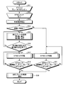
- FIG. 4 is an exemplary flowchart showing a series of processes executed by the brake control device according to the first embodiment.
- FIG. 5 is an exemplary flowchart showing a series of processes executed by the brake control device according to the second embodiment.
- FIG. 1 is a schematic configuration diagram of a brake device that is a control target of the brake control device of the embodiment.
- the brake device 100 is provided, for example, in a four-wheel general vehicle.
- the brake device 100 is configured such that a braking force (friction braking torque) can be applied to both the front wheels 2FL and 2FR and the rear wheels 2RL and 2RR.
- a braking force (friction braking torque) can be applied to both the front wheels 2FL and 2FR and the rear wheels 2RL and 2RR.
- (Hydraulic braking unit) 1 and an electric parking brake 2 configured to be able to apply braking force only to the wheels 2RL and 2RR which are rear wheels.
- the braking force generated by the hydraulic brake 1 is hydraulically controlled. It is expressed as power, and the braking force generated by the electric parking brake 2 is expressed as parking braking force.
- the hydraulic brake 1 includes a pressure generating unit 32, wheel cylinders 38FL, 38FR, 38RL and 38RR, pressure adjusting units 34FL, 34FR, 34RL and 34RR, and a reflux mechanism 37.
- the pressure generator 32 is a mechanism that generates a pressure (hydraulic pressure) according to the operation of the brake pedal 31 by the driver of the vehicle.
- the wheel cylinders 38FL, 38FR, 38RL, and 38RR are mechanisms that apply braking force to the wheels 2FL, 2FR, 2RL, and 2RR by pressurizing the friction braking member, respectively.
- the pressure adjusting units 34FL, 34FR, 34RL and 34RR are mechanisms for adjusting the hydraulic pressure applied to the wheel cylinders 38FL, 38FR, 38RL and 38RR, respectively.
- the reflux mechanism 37 is a mechanism that returns fluid (working fluid) as a medium for generating hydraulic pressure to the upstream side.
- the pressure generating unit 32 includes a master cylinder 32a and a reservoir tank 32b.
- the master cylinder 32a is pushed in along with the operation (depression) of the brake pedal 31 to discharge the fluid replenished from the reservoir tank 32b to the two discharge ports.
- These two discharge ports are respectively connected to the front-side pressure adjusting unit 34FR and the rear-side pressure adjusting unit 34RL, and the front-side pressure via an electromagnetic valve 33 that can be electrically switched between an open state and a closed state.
- the adjustment unit 34FL and the rear pressure adjustment unit 34RR are connected to each other.
- the electromagnetic valve 33 opens and closes based on the control of a brake control device 200 (see FIG. 3) described later.
- the pressure adjustment units 34FL, 34FR, 34RL, and 34RR have electromagnetic valves 35 and 36 that can be electrically switched between an open state and a closed state, respectively.
- the electromagnetic valves 35 and 36 are provided between the electromagnetic valve 33 and the reservoir 41.
- the electromagnetic valve 35 is connected to the electromagnetic valve 33, and the electromagnetic valve 36 is connected to the reservoir 41.
- the electromagnetic valves 35 and 36 are opened and closed based on the control of the brake control device 200 (see FIG. 3), thereby increasing or maintaining the pressure generated in the wheel cylinders 38FL, 38FR, 38RL and 38RR, or reducing the pressure. It is possible to do.
- the wheel cylinder 38FL is connected between the electromagnetic valves 35 and 36 of the pressure adjusting unit 34FL
- the wheel cylinder 38FR is connected between the electromagnetic valves 35 and 36 of the pressure adjusting unit 34FR.
- the wheel cylinder 38RL is connected between the electromagnetic valves 35 and 36 of the pressure adjustment unit 34RL
- the wheel cylinder 38RR is connected between the electromagnetic valves 35 and 36 of the pressure adjustment unit 34RR.
- the reflux mechanism 37 includes a reservoir 41 and a pump 39, and a pump motor 40 that rotates the front and rear pumps 39 to transport the fluid upstream.
- One reservoir 41 and one pump 39 are provided corresponding to the combination of the pressure adjustment units 34FR and 34RL and the combination of the pressure adjustment units 34FL and 34RR, respectively.
- the hydraulic brake 1 includes a stroke sensor 51 that can detect the operation amount (stroke) of the brake pedal 31, a pressure sensor (not shown in FIG. 1) that can detect the pressure generated in the master cylinder 32a, and the like. Is provided.
- an electric parking brake (EPB: Electric) that is driven on each of the rear wheel cylinders 38RL and 38RR based on the control of the brake control device 200 (see FIG. 3).
- Parking Brake A motor 60 is connected.
- the braking force is applied to the rear wheels 2RL and 2RR by pressurizing the friction braking members of the wheel cylinders 38RL and 38RR on the rear side according to the driving of the electric parking brake motor 60. Is done.
- the rear side wheel cylinders 38RL and 38RR and the two electric parking brake motors 60 connected to the two wheel cylinders 38RL and 38RR represent the hydraulic braking force by the hydraulic brake 1. It functions as an electric parking brake 2 capable of generating a separate parking braking force.
- the driver operates the hydraulic brake 1 to generate a hydraulic braking force (hydraulic brake operation) and the electric parking brake 2.
- a hydraulic braking force hydraulic brake operation
- parking brake operation By appropriately using an operation for generating a parking braking force (parking brake operation), it is possible to generate an appropriate braking force on the vehicle according to the situation. For example, in a situation where the vehicle is stopped only by hydraulic brake operation, if sufficient parking braking force is obtained by subsequent parking brake operation, the hydraulic brake operation is canceled and the hydraulic braking force becomes zero. Even if it becomes, the parking state is maintained as it is.
- the brake device 3RL and the brake device 3RR configured as the electric parking brake 2 will be described.
- the brake device 3RR provided on the right rear wheel 2RR will be described as an example.
- FIG. 2 is a side view of the brake device provided on the right rear wheel from the outside in the vehicle width direction.
- the brake device 3RR is configured as a drum brake, and is accommodated inside a peripheral wall (not shown) of a cylindrical wheel of the right rear wheel 2RR.
- the brake device 3RR includes two brake shoes 13L and 13T that are separated from each other in the front-rear direction.
- the two brake shoes 13L and 13T extend in an arc shape along the inner peripheral surface 12a of the cylindrical drum 12.
- the drum 12 rotates integrally with the wheel of the right rear wheel 2RR around the rotation center C along the vehicle width direction.
- the brake device 3RR moves the two brake shoes 13L and 13T so as to come into contact with the inner peripheral surface 12a of the cylindrical drum 12, and the friction between the brake shoes 13L and 13T and the drum 12 causes the drum 12 and thus the right side.
- the rear wheel 2RR is braked.
- the right brake shoe 13L in FIG. 2 is an example of a leading shoe
- the left brake shoe 13T is an example of a trailing shoe.
- the brake shoes 13L and 13T are examples of a braking member.
- the brake device 3RR includes a wheel cylinder 38RR that operates by hydraulic pressure and an electric parking brake motor 60 that operates by energization (see FIG. 1) as actuators that move the brake shoes 13L and 13T.
- the wheel cylinder 38RR and the electric parking brake motor 60 can move the two brake shoes 3L and 3T, respectively.
- the wheel cylinder 38RR is used, for example, for braking while traveling, and the electric parking brake motor 60 is used, for example, for braking during parking. That is, the brake device 1 is an example of an electric parking brake.
- the electric parking brake motor 60 may be used for braking during traveling.
- the brake device 3RR includes a disc-shaped back plate 14.
- the back plate 14 is provided in a posture intersecting with the rotation center C. That is, the back plate 14 extends substantially along the direction intersecting with the rotation center C, specifically, substantially along the direction orthogonal to the rotation center C.
- the back plate 14 directly or indirectly supports each component of the brake device 3RR.
- the back plate 14 supports components positioned outward in the vehicle width direction from the back plate 14 as shown in FIG. Further, the back plate 14 supports components (not shown) positioned inward in the vehicle width direction with respect to the back plate 14.
- the parts positioned inward in the vehicle width direction supported by the back plate 14 are, for example, an electric parking brake motor 60 and a movement that converts the rotation of the electric parking brake motor 60 into a linear movement of the cable 62 (or rod).
- a conversion mechanism (not shown).
- the back plate 4 is an example of a support member.
- the cable 62 can also be referred to as an operating member.
- the back plate 14 is coupled to a connection member (not shown) with the vehicle body.
- the connection member is, for example, a part of the suspension (for example, an arm, a link, an attachment member, etc.).
- the opening 14a provided in the back plate 14 is used for coupling with the connection member.
- axle shaft (not shown) passes through the opening 14b provided at the approximate center of the back plate 14.
- the rotation center C1 is substantially parallel to the rotation center C of the wheel of the right rear wheel 2RR.
- the rotation center C1 is also referred to as a rotation support point.
- the wheel cylinder 38RR is supported on the upper part of the back plate 14.
- the wheel cylinder 38RR has two pressing portions 21L and 21T that can project in the vehicle front-rear direction (left-right direction in FIG. 1).
- the wheel cylinder 38RR protrudes the two pressing portions 1L and 21T in accordance with the pressurization of the internal pressure chamber.
- the protruding two pressing portions 21L and 21T press the upper portions 13b of the brake shoes 13L and 13T, respectively. Due to the protrusion of the two pressing portions 21L and 21T, the two brake shoes 13L and 13T respectively rotate about the rotation center C1 and move so that the upper portions 13b are separated from each other in the vehicle front-rear direction. Accordingly, the two brake shoes 13L and 13T move outward in the radial direction of the rotation center C of the wheel of the right rear wheel 2RR.
- a belt-like lining 13c along the cylindrical surface is provided on the outer periphery of each brake shoe 13L, 13T.
- the lining 13c and the inner peripheral surface 12a of the drum 12 come into contact with each other by the movement of the two brake shoes 13L and 13T radially outward of the rotation center C, and the friction between the lining 13c and the inner peripheral surface 12a.
- the stroke between the non-braking position and the braking position of the brake shoes 13L and 13T is very small, for example, 1 mm or less.
- the brake device 3RR includes a return member 15.
- the return member 15 removes the two brake shoes 13L and 13T from the drum 12 It acts so as to return from a position (braking position) in contact with the inner peripheral surface 12a to a position not in contact with the inner peripheral surface 12a of the drum 12 (non-braking position).
- the return member 15 is an elastic member such as a coil spring, for example, and applies a force in a direction in which the brake shoe 13L approaches the brake shoe 13T and a force in a direction in which the brake shoe 13T approaches the brake shoe 13L. That is, the return member 15 applies a force in the direction in which the two brake shoes 13L and 13T are separated from the inner peripheral surface 12a of the drum 12.
- the return member 15 is also referred to as an urging member or an elastic member.
- the brake device 3RR includes a moving mechanism 16 as the electric parking brake 2. Based on the operation of an electric parking brake motor 60 and a drive mechanism (not shown) including a motion conversion mechanism, the moving mechanism 16 moves the two brake shoes 13L and 13T from the non-braking position to the braking position.
- the moving mechanism 16 is provided outside the back plate 14 in the vehicle width direction.
- the moving mechanism 16 includes a pressing lever 61, a cable 62, and a wheel cylinder 38RR.
- the pressing lever 61 is provided between one of the two brake shoes 13L and 13T, for example, the left brake shoe 13T and the back plate 14 in FIG. 2, and rotates around the rotation center C2 around the brake shoe 13T. It is supported movably.
- the rotation center C2 is located at the end of the brake shoe 13L opposite to the rotation center C1 (upper side in FIG. 2) and is substantially parallel to the rotation center C1.
- the cable 62 moves substantially along the back plate 14, and moves the lower end portion 61a of the pressing lever 61 on the side far from the rotation center C2 on the other side, for example, in the direction approaching the right brake shoe 3L in FIG. Will move.
- the operating position PL1 where the pressing lever 61 is moved by the cable 62 is indicated by a two-dot chain line in FIG.
- the pressing lever 61 has a protrusion 61b that contacts the inner peripheral surface of the brake shoe 13T. By this protrusion 61b, the initial position PL0 in a state before being moved by the cable 62 of the pressing lever 61 is determined.
- the protrusion 61b is also referred to as an initial position setting unit.
- the pressing portions 21L and 21T which are movable parts movably accommodated in the wheel cylinder 38RR, include a pressing lever 61 that is moved by the cable 62, and a brake shoe 13T that is connected to the pressing lever 61. Can be stretched by being interposed between another brake shoe 13L.
- the connection position P1 between the pressing lever 61 and the pressing portion 21T which is a movable part, is set between the rotation center C2 and the connection position P2 between the cable 62 and the pressing lever 61.
- the brake shoe 13L rotates around the rotation center C1 from the non-braking position (arrow c) and moves to the braking position in contact with the inner peripheral surface 12a of the drum 12.
- the connection position P2 between the cable 62 and the pressing lever 61 corresponds to a force point
- the rotation center C2 corresponds to a fulcrum
- the connection position P1 between the pressing lever 61 and the pressing parts 21L and 21T that are movable parts corresponds to an action point.
- the pressing lever 61 moves to the right in FIG. 1, that is, in the direction in which the movable part 110 pushes the brake shoe 3L (arrow b), with the brake shoe 3L in contact with the inner peripheral surface 2a, the movable part 110 is moved.
- the pressing lever 61 rotates in the direction opposite to the direction in which the pressing lever 61 moves, that is, counterclockwise in FIG. 2 (arrow d), with the connection position P1 with the movable part 110 as a fulcrum.
- the brake shoe 13T rotates around the rotation center C1 from the non-braking position, and moves to the braking position where it comes into contact with the inner peripheral surface 12a of the drum 12.
- the brake shoes 13L and 13T are moved from the non-braking position to the braking position by the operation of the moving mechanism 16.
- the connection position P1 between the pressing lever 61 and the movable component 110 serves as a fulcrum.
- the protrusion 61b of the pressing lever 61 contacts the inner peripheral surface of the brake shoe 13T, and the pressing lever 61 returns to the initial position.
- the pressing portions 21L and 21T that are movable parts of the wheel cylinder 38RR are interposed between the brake shoes 13L and 13T together with the pressing lever 61. Functions as a strut to
- the electric parking brake is locked when the driver depresses the brake pedal (when it is turned on) when the vehicle stops on the slope.
- the four-wheel hydraulic stoppage holding state with the hydraulic brake 1 shifts to a state where the vehicle stops with the axial force of only the electric parking brake for the two rear wheels.
- the torque increases due to the self-boosting action (servo), and the input of the pressing lever 61 (see FIG. 2) decreases due to the torque load on the two rear wheels.
- the brake control device 200 avoids a situation in which the braking force is insufficient in the stopped state based on the configuration described below, and maintains the stopped state of the vehicle more reliably. Reduce the load on the mechanism.
- FIG. 3 is an exemplary block diagram illustrating a functional configuration of the brake control device according to the embodiment.
- the brake control device 200 constitutes a part of a brake ECU (Electronic Control Unit) including hardware similar to a normal computer such as a processor or a memory. Note that the brake control device 200 may be integrated with other parts of the brake ECU, or may be configured separately from the other parts.
- a brake ECU Electronic Control Unit
- the brake control device 200 may be integrated with other parts of the brake ECU, or may be configured separately from the other parts.
- the brake control device 200 is configured to be able to control the hydraulic brake 1 and the electric parking brake 2. More specifically, the brake control device 200 includes a detection unit 201 and a control unit 202 including a hydraulic brake control unit 203 and a parking brake control unit 204 as functional configurations.
- the brake control device 200 functions as a gradient detection unit based on the output of the gradient detection sensor 3 configured as an acceleration sensor, a gyro sensor, or the like that detects a road surface gradient (tilt in the front-rear direction of the vehicle).
- the hydraulic brake control unit 203 of the control unit 202 is configured to be able to control the hydraulic braking force generated by the hydraulic brake 1.
- the parking brake control unit 204 is configured to be able to control the parking braking force generated by the electric parking brake 2.
- the detection unit 201 performs an operation such as an operation (hydraulic brake operation) for generating a hydraulic braking force in the hydraulic brake 1 or an operation (parking brake operation) for setting the parking brake force in a state where the parking brake force can be generated.
- the braking operation by the person is detected.
- the hydraulic brake operation is an operation of the brake pedal 31 by the driver, for example.
- the parking brake operation is, for example, an operation of an EPB switch or a lever (not shown in FIG. 1) provided near the driver's seat. That is, the detection unit 201 detects a hydraulic brake operation based on a detection result of the stroke sensor 51 and the like, and detects a parking brake operation based on an electric signal output in response to an operation of an EPB switch or a lever. .
- the control unit 202 When the parking brake operation is detected in a state where the vehicle stop state is maintained only by the hydraulic braking force generated in both the front wheels 2FR, 2FL and the rear wheels 2RR, 2RL, the control unit 202 Before the parking braking force is generated in the vehicle 2, the hydraulic braking force generated on the front wheels 2FR and 2FL is reduced to a predetermined hydraulic braking force corresponding to the road surface inclination, and the fluid generated on the rear wheels 2RR and 2RL. The pressure braking force is adjusted to a size that can maintain the stopped state. That is, the control unit 202 increases the hydraulic braking force of the rear wheels 2RR and 2RL so as to compensate for the braking force that is insufficient due to the decrease in the hydraulic braking force of the front wheels 2FR and 2FL. Thereby, for example, even when the hydraulic braking force of the front wheels 2FR and 2FL is reduced to a predetermined hydraulic braking force, the stopped state can be reliably maintained.
- the hydraulic braking force generated in the front wheels 2FR and 2FL is set to a predetermined hydraulic braking force according to the road surface gradient
- the predetermined hydraulic braking force is set. Set to zero.
- the stationary state can be maintained only by the hydraulic braking force of the rear wheels 2RR and 2RL, and the pressure depressurization amount of the wheel cylinder in the state in which the pressing lever is pressed to the drum side can be eliminated. It becomes possible to almost eliminate the decrease in the pressing force.
- the control unit 202 causes the electric parking brake 2 to generate a parking braking force on the rear wheels 2RR and 2RL. . Accordingly, even when a torque that changes the position of the parking lever is applied due to a decrease in the hydraulic braking force generated on the front wheels 2FR and 2FL, at that time, the parking control for the rear wheels 2RR and 2RL by the electric parking brake 2 is performed. Without affecting the power, it prevents the parking lever input from dropping due to the torque load on the rear wheels 2RR and 2RL, and locks the electric parking brake with a small parkin lever input considering self-boost action (servo) Slope parking is possible.
- servo self-boost action
- control unit 202 sets the electric parking brake so that the timing at which the hydraulic braking force generated on the front wheels 2FR, 2FL decreases to a predetermined hydraulic braking force coincides with the timing at which the parking braking force starts to be generated.
- the timing for driving the second electric parking brake motor 60 may be controlled. By controlling the timing in this way, it is possible to quickly shift from a stopping state using only the hydraulic braking force to a stopping state using only the parking braking force.
- control unit 202 reduces the hydraulic braking force generated in the front wheels 2FR and 2FL when the magnitude of the parking braking force reaches a level capable of maintaining the stop state only by the parking braking force.
- the control and the control for adjusting the hydraulic braking force generated in the rear wheels 2RR and 2RL are released. Accordingly, by releasing the control for reducing the hydraulic braking force of the rear wheel, unnecessary control burden can be reduced, and by releasing the control for adjusting the hydraulic braking force of the front wheel, the brake mechanism for the front wheel is released. It is possible to suppress an unnecessary load from being applied.
- the control unit 202 determines that the magnitude of the hydraulic braking force generated on the rear wheels 2RR and 2RL is in the stopped state.
- the size is larger than the maintainable size, the adjustment of the hydraulic braking force generated in the rear wheels 2RR and 2RL is omitted, and the hydraulic braking force generated in the front wheels 2FR and 2FL is reduced.
- adjustment of the hydraulic braking force of the rear wheels 2RR and 2RL is not performed until the hydraulic braking force sufficient to maintain the stop state is already secured, thereby reducing unnecessary control burden. be able to.
- control unit 202 as an example, the hydraulic brake 1 and the electric parking brake 2 so that the load applied to the front wheels and the rear wheels changes along a timing chart as described below. To control.
- FIG. 4 is an exemplary flowchart showing a series of processes executed by the brake control device according to the first embodiment.
- the brake control device 200 includes an acceleration sensor and a gyro sensor. Based on the output of the gradient detection sensor 3 or the like, the inclination of the vehicle in the front-rear direction, that is, the gradient of the road surface is detected (step S13).
- step S14 it is determined whether or not the vehicle is parked on the slope on the basis of the detected forward / backward inclination of the vehicle, that is, the gradient of the road surface (step S14). If it is determined in step S14 that the vehicle is parked on the slope (step S14; Yes), first, the control unit 202 of the brake control device 200 functions as the hydraulic brake control unit 203 and detects the detected road surface. The hydraulic pressure supplied to the front wheel cylinders 38FR, 38FL in the two front wheels 2FR, 2FL is reduced by hydraulic brake control according to the gradient, and the rear wheel cylinders 38RR, 38RL in the two rear wheels 2RR, 2RL are applied. Control to pressurize the supplied hydraulic pressure is started.
- the target value for the pressure reduction of the hydraulic pressure supplied to the front wheel cylinders 38FR and 38FL in the two front wheels 2FR and 2FL is a value corresponding to the road surface gradient of the slope. Specifically, the smaller the road surface gradient, the smaller the value is set. This is because as the road surface gradient increases, the relative movement of the brake shoes 13L and 13T with respect to the drum 12 in the brake devices 3RR and 3RL on the rear side increases due to the pressure reduction of the two front wheels 2FR and 2FL. This is because it becomes larger.
- the target value of pressurization of the hydraulic pressure supplied to the rear wheel cylinders 38RR and 38RL in the two rear wheels 2RR and 2RL is determined by the vehicle on the slope when the pressure reduction in the two front wheels 2FR and 2FL is completed. It is the pressure that can obtain the hydraulic braking force that can be parked. In other words, the amount of pressure is set according to the amount of pressure reduction in the two front wheels 2FR, 2FL. Subsequently, the hydraulic brake control unit 203 determines whether or not the pressure reduction corresponding to the two front wheels 2FR and 2FL and the pressurization corresponding to the two rear wheels 2RR and 2RL have ended (step S16).
- step S16 If it is determined in step S16 that the pressure reduction corresponding to the two front wheels 2FR and 2FL and the pressurization corresponding to the two rear wheels 2RR and 2RL have not been completed yet (step S16; No), the process is performed again in step S15. Then, the hydraulic pressure of the two front wheels 2FR, 2FL is reduced by the hydraulic brake control, and the control of increasing the hydraulic pressure of the two rear wheels 2RR, 2RL is continued. In the determination of step S16, when the pressure reduction corresponding to the two front wheels 2FR, 2FL and the pressure application corresponding to the two rear wheels 2RR, 2RL are completed, the vehicle caused by the pressure reduction corresponding to the two front wheels 2FR, 2FL.
- the control unit 202 of the brake control device 200 functions as the parking brake control unit 204 and activates the electric parking brake lock (step S17).
- the control unit 202 of the brake control device 200 functions as the parking brake control unit 204 and activates the electric parking brake lock (step S17).
- the control unit 202 of the brake control device 200 functions as the parking brake control unit 204 and activates the electric parking brake lock (step S17).
- the control unit 202 of the brake control device 200 functions as the parking brake control unit 204 and activates the electric parking brake lock (step S17).
- the control unit 202 of the brake control device 200 functions as the parking brake control unit 204 and activates the electric parking brake lock (step S17).
- a time point when the pitching amount becomes smaller than a predetermined threshold may be detected by an acceleration sensor or a gyro sensor capable of measuring pitching.
- the electric parking brake motor 60 is operated, and the operation of the electric parking brake motor 60 pulls the cable 62 and moves it to the right in FIG.
- the brake shoe 13L rotates around the rotation center C1 from the non-braking position (arrow c), moves to the braking position in contact with the inner peripheral surface 12a of the drum 12, and generates a braking force.
- connection position P2 between the cable 62 and the pressing lever 61 corresponds to a force point
- the rotation center C2 corresponds to a fulcrum
- the connection position P1 between the pressing lever 61 and the pressing parts 21L and 21T, which are movable parts corresponds to an action point.
- the pressing lever 61 moves to the right in FIG. 2, that is, in the direction in which the movable part 110 pushes the brake shoe 3L (arrow b), with the brake shoe 13L in contact with the inner peripheral surface 12a, the movable part 110 is moved. Will be stretched.
- the pressing lever 61 pivots in the direction opposite to the direction in which the pressing lever 61 moves, that is, counterclockwise in FIG. 2 (arrow d), with the connection position P1 with the movable part 110 as a fulcrum. Rotates from the non-braking position around the rotation center C1, moves to the braking position in contact with the inner peripheral surface 12a of the drum 12, and generates a braking force.
- step S18 determines whether control of the electric parking brake lock was complete
- step S18 when the control of the electric parking brake lock is finished and the brake pedal is turned off by the driver, the control unit 202 of the brake control device 200 functions as the hydraulic brake control unit 203. Then, pressure reduction is performed so that the hydraulic braking force of the two front wheels 2FR, 2FL and the hydraulic braking force of the two rear wheels 2RR, 2RL are made zero (step S19), and the process is terminated.
- step S14 if it is determined in step S14 that the vehicle is not parked on the slope (step S14; No), the control unit 202 of the brake control device 200 functions as the parking brake control unit 204 according to the above-described procedure.
- the parking brake lock is activated (step S17), and it is determined whether or not the control of the electric parking brake lock is finished and the brake pedal is turned off by the driver (step S21).
- step S21 If it is determined in step S21 that the electric parking brake lock control has not yet been completed or the brake pedal has not been turned off by the driver, the process proceeds to step S20 again.
- step S21 when the control of the electric parking brake lock is finished and the brake pedal is turned off by the driver (step S21; Yes), the control unit 202 of the brake control device 200 performs the hydraulic brake. It functions as the control unit 203, performs pressure reduction to make the hydraulic braking force of the two rear wheels 2RR, 2RL zero (step S19), and ends the process.
- the brake shoe of the drum brake of the rear wheel that functions as the electric parking brake is pressed by the pressing lever.
- the braking force hydroaulic braking force
- the liquid in the wheel cylinder of the front wheel when the pressing lever is pressed toward the drum side is reduced.
- the amount of pressure reduction can be reduced, the reduction of the pressing force by the pressing lever can be suppressed, and the braking force can be ensured more reliably.
- the electric parking brake lock is activated after the pressure reduction of the front wheels 2FR and 2FL and the pressure increase of the rear wheels 2RR and 2RL are completed. Electric parking brake lock control takes some time.
- the second embodiment is an embodiment for shortening the effective time until the end of the electric parking brake lock control while suppressing the decrease of the O pressure by the pressing lever.
- FIG. 5 is an exemplary flowchart showing a series of processes executed by the brake control device according to the second embodiment.
- the brake control device 200 includes an acceleration sensor and a gyro sensor. Based on the output of the gradient detection sensor 3 or the like, the vehicle front-rear direction inclination, that is, the road surface gradient is detected (step S33). Subsequently, it is determined whether or not the vehicle is parked on the slope on the basis of the detected forward / backward inclination of the vehicle, that is, the gradient of the road surface (step S34).
- step S34 If it is determined in step S34 that the vehicle is parked on the slope (step S34; Yes), first, the control unit 202 of the brake control device 200 functions as the hydraulic brake control unit 203 and detects the detected road surface.
- the hydraulic pressure supplied to the front wheel cylinders 38FR, 38FL in the two front wheels 2FR, 2FL is reduced by hydraulic brake control according to the gradient, and the rear wheel cylinders 38RR, 38RL in the two rear wheels 2RR, 2RL are applied.
- Control for pressurizing the supplied hydraulic pressure is started with a pressure reduction target value and a pressure target value similar to those in the first embodiment (step S35).
- the parking brake control unit 204 operates the EPB lock (step S36).
- the pressing lever 61 moves from the initial position PL0 in a direction approaching the brake shoe 13L, but the position immediately before the pressing lever 61 contacts the pressing portion 21L that is a movable part of the wheel cylinder 38RR or the pressing portion 21L.
- the brake shoe 13L is pushed through the pressing portion 21L, but the brake shoe 13L is gradually moved to a position where it does not contact the inner peripheral surface 12a of the drum 12.
- step S37 determines whether or not the pressure reduction corresponding to the two front wheels 2FR and 2FL and the pressurization corresponding to the two rear wheels 2RR and 2RL have ended. If it is determined in step S37 that the pressure reduction corresponding to the two front wheels 2FR and 2FL and the pressurization corresponding to the two rear wheels 2RR and 2RL have not been completed yet (step S37; No), the process is performed again in step S15. Then, the hydraulic pressure of the two front wheels 2FR, 2FL is reduced by the hydraulic brake control, and the control of increasing the hydraulic pressure of the two rear wheels 2RR, 2RL is continued.
- step S37 If the pressure reduction corresponding to the two front wheels 2FR, 2FL and the pressure reduction corresponding to the two rear wheels 2RR, 2RL are completed in the determination in step S37, the vehicle caused by the pressure reduction corresponding to the two front wheels 2FR, 2FL.
- the control unit 202 of the brake control device 200 functions as the parking brake control unit 204, and the electric parking brake lock of the electric parking brake motor 60 is
- the drive current becomes the target current, and the brake shoe 13L and the brake shoe 13T move to the braking position where they come into contact with the inner peripheral surface 12a of the drum 12, and are operated until a predetermined braking force can be generated (step S38).
- step S39 determines whether control of the electric parking brake lock was complete
- step S39 when the control of the electric parking brake lock is finished and the brake pedal is turned off by the driver, the control unit 202 of the brake control device 200 functions as the hydraulic brake control unit 203. Then, pressure reduction is performed so that the hydraulic braking force of the two front wheels 2FR, 2FL and the hydraulic braking force of the two rear wheels 2RR, 2RL are made zero (step S40), and the process is terminated.
- step S34 if it is determined in step S34 that the vehicle is not parked on the slope (step S34; No), it immediately shifts to the electric parking brake lock operating state, resulting from the decompression corresponding to the two front wheels 2FR, 2FL.
- the control unit 202 of the brake control device 200 functions as the parking brake control unit 204, and the electric parking brake lock is set to the electric parking brake motor 60.
- the drive current becomes the target current, and the brake shoe 13L and the brake shoe 13T move to the braking position where they come into contact with the inner peripheral surface 12a of the drum 12, and are operated until a predetermined braking force can be generated (step S41).
- step S42 determines whether control of the electric parking brake lock was complete
- step S42 when the control of the electric parking brake lock is finished and the brake pedal is turned off by the driver, the control unit 202 of the brake control device 200 functions as the hydraulic brake control unit 203. Then, pressure reduction is performed so that the hydraulic braking force of the two front wheels 2FR, 2FL and the hydraulic braking force of the two rear wheels 2RR, 2RL are made zero (step S40), and the process is terminated.
- the brake shoe of the rear wheel drum brake that functions as the electric parking brake is pressed by the pressing lever.
- the braking force (hydraulic braking force) on the front wheel side of the vehicle is reduced based on the gradient of the road surface on which the vehicle is to park, and the pressing lever 61 is moved to the pressing portion 21L which is a movable part of the wheel cylinder 38RR. Since the brake shoe 13L is pressed through the pressing portion 21L and the brake shoe 13L is gradually moved to a position immediately before the contact or the pressing portion 21L, the brake shoe 13L is gradually moved to a position where it does not contact the inner peripheral surface 12a of the drum 12.
- the pressing lever 61 After the electric parking brake switch is turned on, the pressing lever 61 The amount of time until the lock control termination of the dynamic parking brake can be effectively shortened.
Landscapes
- Engineering & Computer Science (AREA)
- Transportation (AREA)
- Mechanical Engineering (AREA)
- Regulating Braking Force (AREA)
- Braking Systems And Boosters (AREA)
Abstract
車両用制動装置は、車両の前輪および後輪のそれぞれに独立して液圧を制御し液圧制動力を発生可能な液圧制動部と、車両の後輪に設けられたドラムに対して相対的に移動可能な制動シューをドラム側に押圧する押圧レバーと、押圧レバーを駆動する電動アクチュエータと、路面の勾配を検出する勾配検出部と、車両の駐車時に液圧制動部における前輪に対応する液圧を路面の勾配に対応する所定圧まで減圧させる制御を行い、前記減圧の完了後に前記電動アクチュエータにより前記押圧レバーを駆動する制御を行う制御部と、を備える。
Description
本発明は、車両用制動装置に関する。
従来、液圧ブレーキによる液圧制動力と、電動駐車ブレーキによる駐車制動力とが所定の車輪に重複して発生することに起因する負荷を低減するため、電動駐車ブレーキの作動時に液圧制動力を低下させる技術が提案されている。
ところで、ドラムブレーキを有する電動駐車ブレーキを備えた車両において、勾配のある路面に駐車する場合に、液圧ブレーキから電動駐車ブレーキに切り替える際に、制動シューがドラムに押圧された状態で前輪の液圧が減圧されることに伴って制動シューがドラムに対して相対移動してしまい、押圧レバーによる押圧力、ひいては、制動力が低下して必要な制動力を確保できなくなる虞があった。
これを解決するため、ドラムブレーキの押圧レバーを電動アクチュエータにより駆動されるケーブルにより駆動する電動駐車ブレーキ装置において、押圧レバーの押圧力を発生させるケーブルの緩みを見越した、より高い目標トルクで制御を行う技術が提案されている。
しかしながら、このような電動駐車ブレーキ装置は、目標トルクを達成するために必要な強度を持たせる必要があり、信頼性向上のためのコストがかかる虞があった。また、ケーブルの緩みを検出するセンサを設けるとした場合には、装置構成が複雑化するとともに、部品点数の増大によるコストが増大する虞があった。
そこで、本発明は、坂路停車時に液圧ブレーキから電動駐車ブレーキに切り替える場合でも、所望の制動力を維持することができる簡素な構成の車両用制動装置を提供することを目的としている。
本発明による車両用制動装置は、車両の前輪および後輪のそれぞれに独立して液圧を制御し液圧制動力を発生可能な液圧制動部と、車両の後輪に設けられたドラムに対して相対的に移動可能な制動シューをドラム側に押圧する押圧レバーと、押圧レバーを駆動する電動アクチュエータと、を有する車両用制動装置であって、路面の勾配を検出する勾配検出部と、車両の駐車時に液圧制動部における前輪に対応する液圧を路面の勾配に対応する所定圧まで減圧させる制御を行い、減圧の完了後に電動アクチュエータにより押圧レバーを駆動する制御を行う制御部と、を備える。
前輪に対応する液圧を所定圧まで減圧させた後で押圧レバーを駆動するので、制動シューがドラムに押圧された状態における前輪液圧の減圧量を低減させることができる。これにより、前輪液圧の減圧に伴う制動シューの相対移動を抑制し、制動力の低下を抑制して必要な制動力を確保することができる。
前輪に対応する液圧を所定圧まで減圧させた後で押圧レバーを駆動するので、制動シューがドラムに押圧された状態における前輪液圧の減圧量を低減させることができる。これにより、前輪液圧の減圧に伴う制動シューの相対移動を抑制し、制動力の低下を抑制して必要な制動力を確保することができる。
以下、本発明の実施形態を図面に基づいて説明する。以下に記載する実施形態の構成、ならびに当該構成によってもたらされる作用および結果(効果)は、あくまで一例であって、以下の記載内容に限られるものではない。
図1は、実施形態のブレーキ制御装置の制御対象であるブレーキ装置の概要構成図である。
ブレーキ装置100は、例えば、たとえば四輪の一般的な車両に設けられる。
ブレーキ装置100は、例えば、たとえば四輪の一般的な車両に設けられる。
実施形態によるブレーキ装置100は、前輪である車輪2FLおよび2FRと、後輪である車輪2RLおよび2RRと、の両方に制動力(摩擦制動トルク)を付与することが可能に構成された液圧ブレーキ(液圧制動部)1と、後輪である車輪2RLおよび2RRのみに制動力を付与することが可能に構成された電動駐車ブレーキ2と、を備える。
以下の説明においては、液圧ブレーキ1が発生する制動力と、電動駐車ブレーキ2が発生する制動力と、を区別する必要がある場合には、液圧ブレーキ1が発生する制動力を液圧制動力と表記し、電動駐車ブレーキ2が発生する制動力を駐車制動力と表記するものとする。
液圧ブレーキ1は、圧力発生部32と、ホイールシリンダ38FL、38FR、38RLおよび38RRと、圧力調整部34FL、34FR、34RLおよび34RRと、還流機構37と、を備える。
圧力発生部32は、車両の運転者によるブレーキペダル31の操作に応じた圧力(液圧)を発生させる機構である。
ホイールシリンダ38FL、38FR、38RLおよび38RRは、それぞれ、摩擦制動部材を加圧することで車輪2FL、2FR、2RL、および2RRに制動力を付与する機構である。
圧力調整部34FL、34FR、34RLおよび34RRは、それぞれ、ホイールシリンダ38FL、38FR、38RLおよび38RRに与えられる液圧を調整する機構である。還流機構37は、液圧を発生させる媒体としてのフルード(作動流体)を上流側へ戻す機構である。
上記構成において、圧力発生部32は、マスタシリンダ32aと、リザーバタンク32bと、を備える。マスタシリンダ32aは、ブレーキペダル31の操作(踏み込み)に伴って押し込まれることで、リザーバタンク32bから補充されるフルードを2つの吐出ポートに吐出する。これら2つの吐出ポートは、それぞれ、開状態と閉状態とを電気的に切り替え可能な電磁弁33を介して、フロント側の圧力調整部34FRおよびリヤ側の圧力調整部34RLと、フロント側の圧力調整部34FLおよびリヤ側の圧力調整部34RRと、に接続される。なお、電磁弁33は、後述するブレーキ制御装置200(図3参照)の制御に基づいて開閉する。
また、圧力調整部34FL、34FR、34RL、および34RRは、それぞれ、開状態と閉状態とを電気的に切り替え可能な電磁弁35および36を有している。電磁弁35および36は、電磁弁33と、リザーバ41と、の間に設けられている。電磁弁35は、電磁弁33に接続され、電磁弁36は、リザーバ41に接続されている。
電磁弁35および36は、ブレーキ制御装置200(図3参照)の制御に基づいて開閉することで、ホイールシリンダ38FL、38FR、38RLおよび38RRで発生する圧力を、昇圧したり、維持したり、減圧したりすることが可能である。なお、ホイールシリンダ38FLは、圧力調整部34FLの電磁弁35および36の間に接続され、ホイールシリンダ38FRは、圧力調整部34FRの電磁弁35および36の間に接続されている。また、ホイールシリンダ38RLは、圧力調整部34RLの電磁弁35および36の間に接続され、ホイールシリンダ38RRは、圧力調整部34RRの電磁弁35および36の間に接続されている。
還流機構37は、リザーバ41およびポンプ39と、フロント側およびリヤ側のポンプ39を回転してフルードを上流側に輸送するポンプモータ40と、を備える。リザーバ41およびポンプ39は、圧力調整部34FRおよび34RLの組み合わせと、圧力調整部34FLおよび34RRの組み合わせと、に対応してそれぞれ1つずつ設けられる。
なお、液圧ブレーキ1には、ブレーキペダル31の操作量(ストローク)を検出可能なストロークセンサ51や、マスタシリンダ32aで発生する圧力を検出可能な圧力センサ(図1には不図示)などが設けられている。
ここで、実施形態では、リヤ側のホイールシリンダ38RLおよび38RRの各々に、ブレーキ制御装置200(図3参照)の制御に基づいて駆動する電動駐車ブレーキ(EPB:Electric
Parking
Brake)モータ60が接続されている。これにより、実施形態では、リヤ側のホイールシリンダ38RLおよび38RRの摩擦制動部材が電動駐車ブレーキモータ60の駆動に応じて加圧されることで、後輪である車輪2RLおよび2RRに制動力が付与される。
Parking
Brake)モータ60が接続されている。これにより、実施形態では、リヤ側のホイールシリンダ38RLおよび38RRの摩擦制動部材が電動駐車ブレーキモータ60の駆動に応じて加圧されることで、後輪である車輪2RLおよび2RRに制動力が付与される。
したがって、実施形態では、リヤ側のホイールシリンダ38RLおよび38RRと、これら2個のホイールシリンダ38RLおよび38RRに接続された2個の電動駐車ブレーキモータ60とが、液圧ブレーキ1による液圧制動力とは別個の駐車制動力を発生可能な電動駐車ブレーキ2として機能する。
ところで、上記のような液圧ブレーキ1および電動駐車ブレーキ2が設けられた車両では、運転者は、液圧ブレーキ1に液圧制動力を発生させる操作(液圧ブレーキ操作)と、電動駐車ブレーキ2に駐車制動力を発生させる操作(駐車ブレーキ操作)と、を適宜使い分けることで、状況に応じて適切な制動力を車両に発生させることが可能である。たとえば、液圧ブレーキ操作のみによって車両が停車状態になっている状況では、その後の駐車ブレーキ操作によって十分な駐車制動力が得られた場合、液圧ブレーキ操作が解除されて液圧制動力がゼロになったとしても、駐車状態がそのまま維持される。
ここで、電動駐車ブレーキ2として構成されたブレーキ装置3RL及びブレーキ装置3RRについて説明する。
この場合において、ブレーキ装置3RL及びブレーキ装置3RRは、同様の構成であるので、右後輪2RRに設けられたブレーキ装置3RRを例として説明する。
この場合において、ブレーキ装置3RL及びブレーキ装置3RRは、同様の構成であるので、右後輪2RRに設けられたブレーキ装置3RRを例として説明する。
図2は、右後輪に設けられたブレーキ装置の車幅方向外方からの側面図である。
ブレーキ装置3RRは、ドラムブレーキとして構成されており、右後輪2RRの円筒状のホイールの周壁(不図示)の内側に収容されている。
ブレーキ装置3RRは、図2に示されるように、前後に離間した二つのブレーキシュー13L、13Tを備えている。二つのブレーキシュー13L、13Tは、円筒状のドラム12の内周面12aに沿って円弧状に伸びている。
ブレーキ装置3RRは、ドラムブレーキとして構成されており、右後輪2RRの円筒状のホイールの周壁(不図示)の内側に収容されている。
ブレーキ装置3RRは、図2に示されるように、前後に離間した二つのブレーキシュー13L、13Tを備えている。二つのブレーキシュー13L、13Tは、円筒状のドラム12の内周面12aに沿って円弧状に伸びている。
ドラム12は、車幅方向に沿う回転中心C回りに、右後輪2RRのホイールと一体に回転する。
そして、ブレーキ装置3RRは、二つのブレーキシュー13L、13Tを、円筒状のドラム12の内周面12aに接触するよう移動させ、ブレーキシュー13L、13Tとドラム12との摩擦によって、ドラム12ひいては右後輪2RRのホイールを制動する。
そして、ブレーキ装置3RRは、二つのブレーキシュー13L、13Tを、円筒状のドラム12の内周面12aに接触するよう移動させ、ブレーキシュー13L、13Tとドラム12との摩擦によって、ドラム12ひいては右後輪2RRのホイールを制動する。
なお、車両の前進時における右後輪2RRのホイールの回転方向Rwが図2において、時計回り方向である場合、図2の右側のブレーキシュー13Lが、リーディングシューの一例であり、左側のブレーキシュー13Tが、トレーリングシューの一例である。
また、ブレーキシュー13L、13Tは、制動部材の一例である。
また、ブレーキシュー13L、13Tは、制動部材の一例である。
ブレーキ装置3RRは、ブレーキシュー13L、13Tを動かすアクチュエータとして、油圧によって作動するホイールシリンダ38RRと、通電によって作動する電動駐車ブレーキモータ60(図1参照)と、を備えている。ホイールシリンダ38RRおよび電動駐車ブレーキモータ60は、それぞれ、二つのブレーキシュー3L,3Tを動かすことができる。ホイールシリンダ38RRは、例えば、走行中の制動に用いられ、電動駐車ブレーキモータ60は、例えば、駐車時の制動に用いられる。すなわち、ブレーキ装置1は、電動パーキングブレーキの一例である。なお、電動駐車ブレーキモータ60は、走行中の制動に用いられてもよい。
ブレーキ装置3RRは、円盤状のバックプレート14を備えている。バックプレート14は、回転中心Cと交差した姿勢で設けられている。すなわち、バックプレート14は、回転中心Cと交差する方向に略沿って、具体的には回転中心Cと直交する方向に略沿って、広がっている。
バックプレート14は、ブレーキ装置3RRの各構成部品を直接的または間接的に支持する。バックプレート14は、図2に示されるような当該バックプレート14よりも車幅方向外方に位置される部品を支持する。また、バックプレート14は、当該バックプレート14よりも車幅方向内方に位置される部品(不図示)を支持する。バックプレート14に支持される車幅方向内方に位置される部品は、例えば、電動駐車ブレーキモータ60や、電動駐車ブレーキモータ60の回動をケーブル62(あるいはロッド)の直動に変換する運動変換機構(不図示)等である。バックプレート4は、支持部材の一例である。また、ケーブル62は、作動部材とも称されうる。
また、バックプレート14は、車体との接続部材(不図示)に結合されている。接続部材は、例えば、サスペンションの一部(例えば、アーム、リンク、取付部材等)である。バックプレート14に設けられた開口部14aは、接続部材との結合に用いられる。
図2のブレーキ装置3RRは、駆動輪および非駆動輪のいずれにも用いることができる。ブレーキ装置3RRが駆動輪に用いられる場合、バックプレート14の略中央に設けられた開口部14bを不図示の車軸が貫通することとなる。
(ホイールシリンダによるブレーキシューの作動)
図2に示されるように、ブレーキシュー13L,13Tの下端部13aは、回動中心C1回りに回動可能に、バックプレート14に支持されている。回動中心C1は、右後輪2RRのホイールの回転中心Cと略平行である。回動中心C1は、回動支持点とも称される。
図2に示されるように、ブレーキシュー13L,13Tの下端部13aは、回動中心C1回りに回動可能に、バックプレート14に支持されている。回動中心C1は、右後輪2RRのホイールの回転中心Cと略平行である。回動中心C1は、回動支持点とも称される。
ホイールシリンダ38RRは、バックプレート14の上部に支持されている。ホイールシリンダ38RRは、車両前後方向(図1の左右方向)に突出可能な二つの押圧部21L、21Tを有する。ホイールシリンダ38RRは、内部の圧力室の与圧に応じて、二つの押圧部1L、21Tを突出させる。
突出した二つの押圧部21L、21Tは、それぞれ、ブレーキシュー13L,13Tの上部13bを押す。二つの押圧部21L、21Tの突出により、二つのブレーキシュー13L,13Tは、それぞれ、回動中心C1回りに回動し、上部13b同士が車両前後方向に互いに離間するように移動する。これにより、二つのブレーキシュー13L,13Tは、右後輪2RRのホイールの回転中心Cの径方向外方に移動する。
各ブレーキシュー13L、13Tの外周部には、円筒面に沿う帯状のライニング13cが設けられている。これにより、二つのブレーキシュー13L、13Tの、回転中心Cの径方向外方への移動により、ライニング13cとドラム12の内周面12aとが接触し、ライニング13cと内周面12aとの摩擦により、ドラム12ひいては、右後輪2RRのホイールが制動される。なお、ブレーキシュー13L,13Tの非制動位置と制動位置との間のストロークは微少であり、例えば1mm以下である。
また、ブレーキ装置3RRは、復帰部材15を備えている。復帰部材15は、ホイールシリンダ38RR内の圧力室が除圧され、押圧部21L、21Tによる二つのブレーキシュー13L、13Tの押圧が解除された場合に、二つのブレーキシュー13L、13Tを、ドラム12の内周面12aと接触する位置(制動位置)からドラム12の内周面12aとは接触しない位置(非制動位置)へ戻すように作用する。
復帰部材15は、例えば、コイルスプリング等の弾性部材であり、ブレーキシュー13Lがブレーキシュー13Tに近づく方向の力及びブレーキシュー13Tがブレーキシュー13Lに近付く方向の力を与える。すなわち、復帰部材15は、二つのブレーキシュー13L、13Tがドラム12の内周面12aから離れる方向の力を与えている。復帰部材15は、付勢部材や弾性部材とも称される。
復帰部材15は、例えば、コイルスプリング等の弾性部材であり、ブレーキシュー13Lがブレーキシュー13Tに近づく方向の力及びブレーキシュー13Tがブレーキシュー13Lに近付く方向の力を与える。すなわち、復帰部材15は、二つのブレーキシュー13L、13Tがドラム12の内周面12aから離れる方向の力を与えている。復帰部材15は、付勢部材や弾性部材とも称される。
また、ブレーキ装置3RRは、電動駐車ブレーキ2として、移動機構16を備えている。電動駐車ブレーキモータ60および運動変換機構を含む駆動機構(不図示)の作動に基づいて、移動機構16は、二つのブレーキシュー13L、13Tを非制動位置から制動位置に移動させる。
移動機構16は、バックプレート14の車幅方向外方に設けられている。移動機構16は、押圧レバー61と、ケーブル62と、ホイールシリンダ38RRと、を含む。
押圧レバー61は、二つのブレーキシュー13L、13Tのうち一方、例えば図2において、左側のブレーキシュー13Tと、バックプレート14との間に設けられ、当該ブレーキシュー13Tに回動中心C2回りに回動可能に支持されている。ここで、回動中心C2は、ブレーキシュー13Lの、回動中心C1とは反対側(図2では上側)の端部に位置され、回動中心C1と略平行である。
ケーブル62は、バックプレート14に略沿って移動し、押圧レバー61の、回動中心C2から遠い側の下端部61aを、他方、例えば、図2においては、右側のブレーキシュー3Lに近付く方向に動かすこととなる。押圧レバー61がケーブル62によって動かされた作動位置PL1は、図2中に二点鎖線で示されている。
ケーブル62は、バックプレート14に略沿って移動し、押圧レバー61の、回動中心C2から遠い側の下端部61aを、他方、例えば、図2においては、右側のブレーキシュー3Lに近付く方向に動かすこととなる。押圧レバー61がケーブル62によって動かされた作動位置PL1は、図2中に二点鎖線で示されている。
押圧レバー61は、ブレーキシュー13Tの内周面に当接する突起61bを有している。この突起61bにより、押圧レバー61のケーブル62によって動かされる前の状態での初期位置PL0が定まっている。突起61bは、初期位置設定部とも称される。
そして、本実施形態では、ホイールシリンダ38RRに移動可能に収容された可動部品である押圧部21L、21Tが、ケーブル62によって動かされる押圧レバー61と、当該押圧レバー61と連結されたブレーキシュー13Tとは別のブレーキシュー13Lと、の間に介在して突っ張ることができる。ここで、押圧レバー61と可動部品である押圧部21Tとの接続位置P1は、回動中心C2と、ケーブル62と押圧レバー61との接続位置P2と、の間に設定されている。
このような構成において、電動駐車ブレーキモータ60の作動によりケーブル62が引かれて図2の右方へ動くことにより、押圧レバー61が、初期位置PL0からブレーキシュー13Lに近付く方向へ動くと(矢印a、作動位置PL1)、押圧レバー61はホイールシリンダ38RRの可動部品である押圧部21Lを介してブレーキシュー13Lを押す(矢印b)。
これにより、ブレーキシュー13Lは、非制動位置から回動中心C1回りに回動し(矢印c)、ドラム12の内周面12aと接触する制動位置へ動く。この状態では、ケーブル62と押圧レバー61との接続位置P2は力点、回動中心C2は支点、押圧レバー61と可動部品である押圧部21L、21Tとの接続位置P1は作用点に相当する。さらに、ブレーキシュー3Lが、内周面2aに接触した状態で、押圧レバー61が図1の右方、すなわち、可動部品110がブレーキシュー3Lを押す方向へ動くと(矢印b)、可動部品110が突っ張ることにより、押圧レバー61は可動部品110との接続位置P1を支点として、押圧レバー61の動く方向とは逆方向、すなわち、図2における反時計回りに回動する(矢印d)。
これにより、ブレーキシュー13Tは、非制動位置から回動中心C1回りに回動し、ドラム12の内周面12aと接触する制動位置へ動く。
上述したように、移動機構16の作動により、ブレーキシュー13L、13Tは、いずれも非制動位置から制動位置へ動くこととなる。なお、ブレーキシュー13Lがドラム12の内周面12aに接触した以降の状態では、押圧レバー61と可動部品110との接続位置P1が支点となる。
また、ブレーキシュー13Lが非制動位置に戻ると同時に押圧レバー61の突起61bがブレーキシュー13Tの内周面に当接し、押圧レバー61が初期位置に戻る。
このように、本実施形態では、ホイールシリンダ38RRの可動部品である押圧部21L、21Tが、ブレーキ装置3RRが電動駐車ブレーキ2として作動する際に、押圧レバー61とともにブレーキシュー13L、13T間に介在するストラットとして機能する。
上述したように、移動機構16の作動により、ブレーキシュー13L、13Tは、いずれも非制動位置から制動位置へ動くこととなる。なお、ブレーキシュー13Lがドラム12の内周面12aに接触した以降の状態では、押圧レバー61と可動部品110との接続位置P1が支点となる。
また、ブレーキシュー13Lが非制動位置に戻ると同時に押圧レバー61の突起61bがブレーキシュー13Tの内周面に当接し、押圧レバー61が初期位置に戻る。
このように、本実施形態では、ホイールシリンダ38RRの可動部品である押圧部21L、21Tが、ブレーキ装置3RRが電動駐車ブレーキ2として作動する際に、押圧レバー61とともにブレーキシュー13L、13T間に介在するストラットとして機能する。
ところで、従来のドラムブレーキを用いた電動駐車ブレーキにおいては、坂路停車時にドライバがブレーキペダルを踏んだ時(オンした時)に、電動駐車ブレーキをロック作動させていたため、電動駐車ブレーキのロック作動終了後にブレーキペダルを踏むのをやめて(オフして)足を離すと、液圧ブレーキ1による4輪液圧停車保持状態から、後輪2輪の電動駐車ブレーキのみの軸力で停車する状態に移行するため、自己倍力作用(サーボ)によるトルクの増加、後輪2輪へのトルク負荷による押圧レバー61(図2参照)の入力低下が発生し、制動力が不足する虞があった。
そこで、実施形態によるブレーキ制御装置200は、以下に説明するような構成に基づき、停車状態で制動力が不足する事態が起こるのを回避し、車両の停車状態をより確実に維持しつつ、ブレーキ機構に加わる負荷を低減する。
図3は、実施形態によるブレーキ制御装置の機能的構成を示した例示的なブロック図である。
ブレーキ制御装置200は、たとえば、プロセッサやメモリなどといった通常のコンピュータと同様のハードウェアを備えたブレーキECU(Electronic Control Unit)の一部を構成する。なお、ブレーキ制御装置200は、ブレーキECUの他の部分と一体化されてもよいし、当該他の部分とは別個に構成されてもよい。
ブレーキ制御装置200は、たとえば、プロセッサやメモリなどといった通常のコンピュータと同様のハードウェアを備えたブレーキECU(Electronic Control Unit)の一部を構成する。なお、ブレーキ制御装置200は、ブレーキECUの他の部分と一体化されてもよいし、当該他の部分とは別個に構成されてもよい。
図3に例示されるように、ブレーキ制御装置200は、液圧ブレーキ1と電動駐車ブレーキ2とを制御可能に構成されている。より具体的に、ブレーキ制御装置200は、機能的構成として、検出部201と、液圧ブレーキ制御部203および駐車ブレーキ制御部204を含んだ制御部202と、を備えている。
また、ブレーキ制御装置200は、路面の勾配(車両の前後方向の傾き)を検出する加速度センサ、ジャイロセンサ等として構成された勾配検知センサ3の出力に基づいて勾配検知部として機能する。
制御部202の液圧ブレーキ制御部203は、液圧ブレーキ1に発生させる液圧制動力を制御可能に構成されている。また、駐車ブレーキ制御部204は、電動駐車ブレーキ2に発生させる駐車制動力を制御可能に構成されている。これらの機能的構成は、たとえば、ブレーキ制御装置200のプロセッサがメモリに格納された種々のプログラムを実行した結果として実現される。なお、実施形態では、これらの機能的構成の一部または全部が専用の回路などによって実現されてもよい。
検出部201は、液圧ブレーキ1に液圧制動力を発生させるための操作(液圧ブレーキ操作)や、駐車制動力を発生可能な状態に設定するための操作(駐車ブレーキ操作)などといった、運転者による制動操作を検出する。
ここで、液圧ブレーキ操作とは、たとえば、運転者によるブレーキペダル31の操作である。一方、駐車ブレーキ操作とは、たとえば、運転席付近に設けられるEPBスイッチやレバー(図1には不図示)などの操作である。
すなわち、検出部201は、ストロークセンサ51などの検出結果に基づいて液圧ブレーキ操作を検出し、EPBスイッチやレバーなどの操作に応じて出力される電気信号などに基づいて駐車ブレーキ操作を検出する。
ここで、液圧ブレーキ操作とは、たとえば、運転者によるブレーキペダル31の操作である。一方、駐車ブレーキ操作とは、たとえば、運転席付近に設けられるEPBスイッチやレバー(図1には不図示)などの操作である。
すなわち、検出部201は、ストロークセンサ51などの検出結果に基づいて液圧ブレーキ操作を検出し、EPBスイッチやレバーなどの操作に応じて出力される電気信号などに基づいて駐車ブレーキ操作を検出する。
制御部202は、前輪2FR、2FLおよび後輪2RR、2RLの両方に発生している液圧制動力のみによって車両の停車状態が維持されている状況で駐車ブレーキ操作が検出された場合、電動駐車ブレーキ2に駐車制動力を発生させる前に、前輪2FR、2FLに発生している液圧制動力を路面の傾斜に応じた所定の液圧制動力まで減少させ、後輪2RR、2RLに発生している液圧制動力を、停車状態を維持可能な大きさに調整する。すなわち、制御部202は、前輪2FR、2FLの液圧制動力の低下によって不足する制動力を補うように、後輪2RR、2RLの液圧制動力を上昇させる。これにより、たとえば前輪2FR、2FLの液圧制動力を所定の液圧制動力まで減少させた場合でも、停車状態を確実に維持することができる。
この場合において、前輪2FR、2FLにおいて発生している液圧制動力を路面の勾配に応じた所定の液圧制動力とするに際し、路面の勾配により設定可能である場合には、所定の液圧制動力をゼロに設定する。これにより、後輪2RR、2RLの液圧制動力のみで停車状態を維持することができ、押圧レバーをドラム側に押圧下状態におけるホイールシリンダの液圧減圧量をなくすことができるので、押圧レバーの押圧力の低下をほぼなくすことが可能となる。
そして、制御部202は、前輪2FR、2FLに発生していた液圧制動力が所定の液圧制動力まで低下した以後に、電動駐車ブレーキ2により後輪2RR、2RLに対し、駐車制動力を発生させる。したがって、前輪2FR、2FLに発生している液圧制動力の減少によりパーキングレバーの位置を変化するようなトルクがかかった場合でも、その時点では、電動駐車ブレーキ2による後輪2RR、2RLに対する駐車制動力に影響を与えることがなく、後輪2RR、2RLへのトルク負荷によるパーキングレバーの入力低下を防止し、自己倍力作用(サーボ)を考慮した少ないパーキンレバー入力で電動駐車ブレーキをロックさせて坂路駐車が可能となる。
なお、制御部202は、前輪2FR、2FLに発生している液圧制動力が所定の液圧制動力まで低下したタイミングと、駐車制動力が発生し始めるタイミングと、が一致するように、電動駐車ブレーキ2の電動駐車ブレーキモータ60を駆動するタイミングを制御してもよい。このようにタイミングを制御すれば、液圧制動力のみによる停車状態から、駐車制動力のみによる停車状態へと速やかに移行することができる。
さらに、制御部202は、駐車制動力の大きさが、当該駐車制動力のみによって停車状態を維持可能な大きさに達した場合に、前輪2FR、2FLに発生している液圧制動力を低下させる制御と、後輪2RR、2RLに発生している液圧制動力を調整する制御と、を解除する。これにより、後輪の液圧制動力を低下させる制御を解除することで、不要な制御負担を低減することができるとともに、前輪の液圧制動力を調整する制御を解除することで、前輪のブレーキ機構に不要な負荷が加わるのを抑制することができる。
なお、一般に、液圧ブレーキ1および電動駐車ブレーキ2の機構上、駐車制動力が停車状態を維持可能な大きさまで上昇して保持された以後は、運転者が液圧ブレーキ操作を行ったとしても、当該液圧ブレーキ操作に応じた液圧制動力が駐車制動力に上乗せされることはない。このため、駐車制動力のみによって停車状態を維持可能な状態になった場合、後輪に発生している液圧制動力を低下させる制御を終了しても、後輪のブレーキ機構に加わる負荷が上昇することはない。
さらに制御部202は、液圧制動力のみによって停車状態が維持されている状況で駐車ブレーキ操作が検出された場合において、後輪2RR、2RLに発生している液圧制動力の大きさが停車状態を維持可能な大きさ以上であるとき、後輪2RR、2RLに発生している液圧制動力の調整を省略し、前輪2FR、2FLに発生している液圧制動力を減少させる。これにより、停車状態を維持するのに十分な液圧制動力が既に確保されている場合にまで後輪2RR、2RLの液圧制動力の調整が行われることがないので、不要な制御負担を低減することができる。
以上の構成により、実施形態による制御部202は、一例として、前輪および後輪に加わる負荷が、以下に説明するようなタイミングチャートに沿って変化するように、液圧ブレーキ1および電動駐車ブレーキ2を制御する。
[1]第1実施形態
次に、第1実施形態によるブレーキ制御装置200の動作についてより詳細に説明する。
図4は、第1実施形態によるブレーキ制御装置が実行する一連の処理を示した例示的なフローチャートである。
次に、第1実施形態によるブレーキ制御装置200の動作についてより詳細に説明する。
図4は、第1実施形態によるブレーキ制御装置が実行する一連の処理を示した例示的なフローチャートである。
まず、ドライバによりブレーキペダルがオンにされ(ステップS11)、電動駐車ブレーキ(図4中、EPBと表記)スイッチがオンにされると(ステップS12)、ブレーキ制御装置200は、加速度センサ、ジャイロセンサ等の勾配検知センサ3の出力に基づいて車両の前後方向の傾き、すなわち、路面の勾配を検出する(ステップS13)。
続いて、検出した車両の前後方向の傾き、すなわち、路面の勾配に基づいて、車両が坂路に駐車しているか否かを判別する(ステップS14)。
ステップS14の判別において、車両が坂路に駐車している場合には(ステップS14;Yes)、まず、ブレーキ制御装置200の制御部202は、液圧ブレーキ制御部203として機能し、検出した路面の勾配に応じて液圧ブレーキ制御により二つの前輪2FR、2FLにおけるフロント側のホイールシリンダ38FR、38FLに供給する油圧を減圧するとともに、二つの後輪2RR、2RLにおけるリヤ側のホイールシリンダ38RR、38RLに供給する油圧を加圧する制御を開始する。
ステップS14の判別において、車両が坂路に駐車している場合には(ステップS14;Yes)、まず、ブレーキ制御装置200の制御部202は、液圧ブレーキ制御部203として機能し、検出した路面の勾配に応じて液圧ブレーキ制御により二つの前輪2FR、2FLにおけるフロント側のホイールシリンダ38FR、38FLに供給する油圧を減圧するとともに、二つの後輪2RR、2RLにおけるリヤ側のホイールシリンダ38RR、38RLに供給する油圧を加圧する制御を開始する。
この場合において、二つの前輪2FR、2FLおけるフロント側のホイールシリンダ38FR、38FLに供給する油圧の減圧の目標値は、坂路の路面勾配に応じた値とされる。具体的には、路面勾配が大きいほど小さい値に設定される。これは、路面勾配が大きいほど二つの前輪2FR、2FLの減圧の影響でリヤ側のブレーキ装置3RR、3RLにおけるブレーキシュー13L、13Tのドラム12に対する相対的な移動量が大きくなり、制動力の変動が大きくなるからである。
また、同じ路面勾配の坂路の場合、降坂路の場合には、登坂路の場合よりも小さい値に設定される。これは、降坂路の場合には二つの前輪2FR、2FLの減圧の影響により車両における荷重移動がより発生しやすく、リヤ側のブレーキ装置3RR、3RLにおけるブレーキシュー13L、13Tのドラム12に対する相対的な移動量が大きくなり、制動力の変動が大きくなるからである。
そして、二つの後輪2RR、2RLおけるリヤ側のホイールシリンダ38RR、38RLに供給する液圧の加圧の目標値は、二つの前輪2FR、2FLにおける減圧が完了した場合に当該車両が当該坂路で駐車が可能な液圧制動力を得られる圧力である。換言すれば、二つの前輪2FR、2FLにおける減圧量に応じた加圧量とされている。
続いて、液圧ブレーキ制御部203は、二つの前輪2FR、2FLに対応する減圧及び二つの後輪2RR、2RLに対応する加圧が終了したか否かを判別する(ステップS16)。
ステップS16の判別において、未だ二つの前輪2FR、2FLに対応する減圧及び二つの後輪2RR、2RLに対応する加圧が終了していない場合には(ステップS16;No)、再び処理をステップS15に移行し、液圧ブレーキ制御により二つの前輪2FR、2FLの油圧を減圧するとともに、二つの後輪2RR、2RLの油圧を加圧する制御を継続する。
ステップS16の判別において、二つの前輪2FR、2FLに対応する減圧及び二つの後輪2RR、2RLに対応する加圧が終了した場合には、二つの前輪2FR、2FLに対応する減圧に起因する車両の揺れ(車両のピッチング)が収まると想定される所定の時間が経過後、ブレーキ制御装置200の制御部202は、駐車ブレーキ制御部204として機能し、電動駐車ブレーキロックを作動させる(ステップS17)。この場合において、車両の揺れ(車両のピッチング)が収まると想定される所定の時間については、車種毎に予め設定しておけば良い。あるいは、ピッチングを測定可能な加速度センサあるいはジャイロセンサによりピッチング量が所定の閾値よりも小さくなった時点を検出するようにしてもよい。
具体的には、電動駐車ブレーキモータ60を作動させ、電動駐車ブレーキモータ60の作動により、ケーブル62が引かれて図2の右方へ動くことにより、押圧レバー61が、初期位置PL0からブレーキシュー13Lに近付く方向へ動き(矢印a、作動位置PL1)、押圧レバー61はホイールシリンダ38RRの可動部品である押圧部21Lを介してブレーキシュー13Lを押す(矢印b)。
続いて、液圧ブレーキ制御部203は、二つの前輪2FR、2FLに対応する減圧及び二つの後輪2RR、2RLに対応する加圧が終了したか否かを判別する(ステップS16)。
ステップS16の判別において、未だ二つの前輪2FR、2FLに対応する減圧及び二つの後輪2RR、2RLに対応する加圧が終了していない場合には(ステップS16;No)、再び処理をステップS15に移行し、液圧ブレーキ制御により二つの前輪2FR、2FLの油圧を減圧するとともに、二つの後輪2RR、2RLの油圧を加圧する制御を継続する。
ステップS16の判別において、二つの前輪2FR、2FLに対応する減圧及び二つの後輪2RR、2RLに対応する加圧が終了した場合には、二つの前輪2FR、2FLに対応する減圧に起因する車両の揺れ(車両のピッチング)が収まると想定される所定の時間が経過後、ブレーキ制御装置200の制御部202は、駐車ブレーキ制御部204として機能し、電動駐車ブレーキロックを作動させる(ステップS17)。この場合において、車両の揺れ(車両のピッチング)が収まると想定される所定の時間については、車種毎に予め設定しておけば良い。あるいは、ピッチングを測定可能な加速度センサあるいはジャイロセンサによりピッチング量が所定の閾値よりも小さくなった時点を検出するようにしてもよい。
具体的には、電動駐車ブレーキモータ60を作動させ、電動駐車ブレーキモータ60の作動により、ケーブル62が引かれて図2の右方へ動くことにより、押圧レバー61が、初期位置PL0からブレーキシュー13Lに近付く方向へ動き(矢印a、作動位置PL1)、押圧レバー61はホイールシリンダ38RRの可動部品である押圧部21Lを介してブレーキシュー13Lを押す(矢印b)。
これにより、ブレーキシュー13Lは、非制動位置から回動中心C1回りに回動し(矢印c)、ドラム12の内周面12aと接触する制動位置へ動き、制動力を発生させることとなる。
この状態では、ケーブル62と押圧レバー61との接続位置P2は力点、回動中心C2は支点、押圧レバー61と可動部品である押圧部21L、21Tとの接続位置P1は作用点に相当する。さらに、ブレーキシュー13Lが、内周面12aに接触した状態で、押圧レバー61が図2の右方、すなわち、可動部品110がブレーキシュー3Lを押す方向へ動くと(矢印b)、可動部品110が突っ張ることとなる。
この結果、押圧レバー61は可動部品110との接続位置P1を支点として、押圧レバー61の動く方向とは逆方向、すなわち、図2における反時計回りに回動し(矢印d)、ブレーキシュー13Tは、非制動位置から回動中心C1回りに回動し、ドラム12の内周面12aと接触する制動位置へ動き、制動力を発生させることとなる。
そして、電動駐車ブレーキロックの制御が終了し、かつ、ドライバによりブレーキペダルがオフにされたか否かを判別する(ステップS18)。
ステップS18の判別において、未だ電動駐車ブレーキロックの制御が終了しておらず、あるいは、ドライバによりブレーキペダルがオフにされていない場合には、処理を再びステップS17に移行する。
ステップS18の判別において、未だ電動駐車ブレーキロックの制御が終了しておらず、あるいは、ドライバによりブレーキペダルがオフにされていない場合には、処理を再びステップS17に移行する。
ステップS18の判別において、電動駐車ブレーキロックの制御が終了し、かつ、ドライバによりブレーキペダルがオフにされた場合には、ブレーキ制御装置200の制御部202は、液圧ブレーキ制御部203として機能し、二つの前輪2FR、2FLの液圧制動力及び二つの後輪2RR、2RLの液圧制動力をゼロとするための減圧を行い(ステップS19)、処理を終了する。
一方、ステップS14の判別において、車両が坂路に駐車していない場合には(ステップS14;No)、上述した手順によりブレーキ制御装置200の制御部202は、駐車ブレーキ制御部204として機能し、電動駐車ブレーキロックを作動させ(ステップS17)、電動駐車ブレーキロックの制御が終了し、かつ、ドライバによりブレーキペダルがオフにされたか否かを判別する(ステップS21)。
ステップS21の判別において、未だ電動駐車ブレーキロックの制御が終了しておらず、あるいは、ドライバによりブレーキペダルがオフにされていない場合には、処理を再びステップS20に移行する。
ステップS21の判別において、電動駐車ブレーキロックの制御が終了し、かつ、ドライバによりブレーキペダルがオフにされた場合には(ステップS21;Yes)、ブレーキ制御装置200の制御部202は、液圧ブレーキ制御部203として機能し、二つの後輪2RR、2RLの液圧制動力をゼロとするための減圧を行い(ステップS19)、処理を終了する。
以上の説明のように、本第1実施形態によれば、液圧ブレーキによる制動から電動駐車ブレーキに切り替える際に、電動駐車ブレーキとして機能する後輪のドラムブレーキのブレーキシューを押圧レバーで押圧するのに先だって、車両が駐車しようとしている路面の勾配に基づいて、車両の前輪側の制動力(液圧制動力)を減少させるので、押圧レバーをドラム側に押圧した状態における前輪のホイールシリンダの液圧減圧量が低減され、押圧レバーによる押圧力の低下を抑制でき、より確実に制動力を確保することができる。
[2]第2実施形態
上記第1実施形態においては、前輪2FR、2FLの減圧及び後輪2RR、2RLの加圧が終了してから、電動駐車ブレーキロックを作動する構成を採っていたが、電動駐車ブレーキロック制御にはそれなりの時間がかかる。本第2実施形態は、押圧レバーによるO圧力の低下を抑制しつつ、電動駐車ブレーキロック制御終了までの実効的な時間を短縮するための実施形態である。
上記第1実施形態においては、前輪2FR、2FLの減圧及び後輪2RR、2RLの加圧が終了してから、電動駐車ブレーキロックを作動する構成を採っていたが、電動駐車ブレーキロック制御にはそれなりの時間がかかる。本第2実施形態は、押圧レバーによるO圧力の低下を抑制しつつ、電動駐車ブレーキロック制御終了までの実効的な時間を短縮するための実施形態である。
図5は、第2実施形態によるブレーキ制御装置が実行する一連の処理を示した例示的なフローチャートである。
まず、ドライバによりブレーキペダルがオンにされ(ステップS31)、電動駐車ブレーキ(図5中、EPBと表記)スイッチがオンにされると(ステップS32)、ブレーキ制御装置200は、加速度センサ、ジャイロセンサ等の勾配検知センサ3の出力に基づいて車両の前後方向の傾き、すなわち、路面の勾配を検出する(ステップS33)。
続いて、検出した車両の前後方向の傾き、すなわち、路面の勾配に基づいて、車両が坂路に駐車しているか否かを判別する(ステップS34)。
続いて、検出した車両の前後方向の傾き、すなわち、路面の勾配に基づいて、車両が坂路に駐車しているか否かを判別する(ステップS34)。
ステップS34の判別において、車両が坂路に駐車している場合には(ステップS34;Yes)、まず、ブレーキ制御装置200の制御部202は、液圧ブレーキ制御部203として機能し、検出した路面の勾配に応じて液圧ブレーキ制御により二つの前輪2FR、2FLにおけるフロント側のホイールシリンダ38FR、38FLに供給する油圧を減圧するとともに、二つの後輪2RR、2RLにおけるリヤ側のホイールシリンダ38RR、38RLに供給する油圧を加圧する制御を第1実施形態と同様の減圧目標値及び加圧目標値で開始する(ステップS35)。
続いて駐車ブレーキ制御部204は、EPBロック作動させる(ステップS36)。
続いて駐車ブレーキ制御部204は、EPBロック作動させる(ステップS36)。
この場合において、押圧レバー61は、初期位置PL0からブレーキシュー13Lに近付く方向へ動かすが、押圧レバー61がホイールシリンダ38RRの可動部品である押圧部21Lに当接する直前の位置、あるいは、押圧部21Lに当接し、押圧部21Lを介してブレーキシュー13Lを押すが、ブレーキシュー13Lがドラム12の内周面12aと接触しない位置まで徐々に動かされることとなる。
続いて、液圧ブレーキ制御部203は、二つの前輪2FR、2FLに対応する減圧及び二つの後輪2RR、2RLに対応する加圧が終了したか否かを判別する(ステップS37)。
ステップS37の判別において、未だ二つの前輪2FR、2FLに対応する減圧及び二つの後輪2RR、2RLに対応する加圧が終了していない場合には(ステップS37;No)、再び処理をステップS15に移行し、液圧ブレーキ制御により二つの前輪2FR、2FLの油圧を減圧するとともに、二つの後輪2RR、2RLの油圧を加圧する制御を継続する。
ステップS37の判別において、二つの前輪2FR、2FLに対応する減圧及び二つの後輪2RR、2RLに対応する加圧が終了した場合には、二つの前輪2FR、2FLに対応する減圧に起因する車両の揺れ(車両のピッチング)が収まると想定される所定の時間が経過後、ブレーキ制御装置200の制御部202は、駐車ブレーキ制御部204として機能し、電動駐車ブレーキロックを電動駐車ブレーキモータ60の駆動電流が目標電流となり、ブレーキシュー13L及びブレーキシュー13Tがドラム12の内周面12aと接触する制動位置まで動き、所定の制動力を発生可能となるまで作動させる(ステップS38)。
ステップS37の判別において、未だ二つの前輪2FR、2FLに対応する減圧及び二つの後輪2RR、2RLに対応する加圧が終了していない場合には(ステップS37;No)、再び処理をステップS15に移行し、液圧ブレーキ制御により二つの前輪2FR、2FLの油圧を減圧するとともに、二つの後輪2RR、2RLの油圧を加圧する制御を継続する。
ステップS37の判別において、二つの前輪2FR、2FLに対応する減圧及び二つの後輪2RR、2RLに対応する加圧が終了した場合には、二つの前輪2FR、2FLに対応する減圧に起因する車両の揺れ(車両のピッチング)が収まると想定される所定の時間が経過後、ブレーキ制御装置200の制御部202は、駐車ブレーキ制御部204として機能し、電動駐車ブレーキロックを電動駐車ブレーキモータ60の駆動電流が目標電流となり、ブレーキシュー13L及びブレーキシュー13Tがドラム12の内周面12aと接触する制動位置まで動き、所定の制動力を発生可能となるまで作動させる(ステップS38)。
そして、電動駐車ブレーキロックの制御が終了し、かつ、ドライバによりブレーキペダルがオフにされたか否かを判別する(ステップS39)。
ステップS39の判別において、未だ電動駐車ブレーキロックの制御が終了しておらず、あるいは、ドライバによりブレーキペダルがオフにされていない場合には、処理を再びステップS38に移行する。
ステップS39の判別において、未だ電動駐車ブレーキロックの制御が終了しておらず、あるいは、ドライバによりブレーキペダルがオフにされていない場合には、処理を再びステップS38に移行する。
ステップS39の判別において、電動駐車ブレーキロックの制御が終了し、かつ、ドライバによりブレーキペダルがオフにされた場合には、ブレーキ制御装置200の制御部202は、液圧ブレーキ制御部203として機能し、二つの前輪2FR、2FLの液圧制動力及び二つの後輪2RR、2RLの液圧制動力をゼロとするための減圧を行い(ステップS40)、処理を終了する。
一方、ステップS34の判別において、車両が坂路に駐車していない場合には(ステップS34;No)、直ちに電動駐車ブレーキロック作動状態に移行し、二つの前輪2FR、2FLに対応する減圧に起因する車両の揺れ(車両のピッチング)が収まると想定される所定の時間が経過後、ブレーキ制御装置200の制御部202は、駐車ブレーキ制御部204として機能し、電動駐車ブレーキロックを電動駐車ブレーキモータ60の駆動電流が目標電流となり、ブレーキシュー13L及びブレーキシュー13Tがドラム12の内周面12aと接触する制動位置まで動き、所定の制動力を発生可能となるまで作動させる(ステップS41)。
そして、電動駐車ブレーキロックの制御が終了し、かつ、ドライバによりブレーキペダルがオフにされたか否かを判別する(ステップS42)。
ステップS42の判別において、未だ電動駐車ブレーキロックの制御が終了しておらず、あるいは、ドライバによりブレーキペダルがオフにされていない場合には、処理を再びステップS41に移行する。
ステップS42の判別において、未だ電動駐車ブレーキロックの制御が終了しておらず、あるいは、ドライバによりブレーキペダルがオフにされていない場合には、処理を再びステップS41に移行する。
ステップS42の判別において、電動駐車ブレーキロックの制御が終了し、かつ、ドライバによりブレーキペダルがオフにされた場合には、ブレーキ制御装置200の制御部202は、液圧ブレーキ制御部203として機能し、二つの前輪2FR、2FLの液圧制動力及び二つの後輪2RR、2RLの液圧制動力をゼロとするための減圧を行い(ステップS40)、処理を終了する。
以上の説明のように、本第2実施形態によれば、液圧ブレーキによる制動から電動駐車ブレーキに切り替える際に、電動駐車ブレーキとして機能する後輪のドラムブレーキのブレーキシューを押圧レバーで押圧するのに先だって、車両が駐車しようとしている路面の勾配に基づいて、車両の前輪側の制動力(液圧制動力)を減少させるとともに、押圧レバー61をホイールシリンダ38RRの可動部品である押圧部21Lに当接する直前の位置、あるいは、押圧部21Lに当接し、押圧部21Lを介してブレーキシュー13Lを押すが、ブレーキシュー13Lがドラム12の内周面12aと接触しない位置まで徐々に動かしておくので、第1実施形態の効果に加えて、電動駐車ブレーキスイッチがオンにされてから、押圧レバー61による電動駐車ブレーキのロック制御終了までの時間を実効的に短くすることができる。
以上、本発明の実施形態を説明したが、上述した実施形態はあくまで一例であって、発明の範囲を限定することは意図していない。上述した新規な実施形態は、様々な形態で実施されることが可能であり、発明の要旨を逸脱しない範囲で、種々の省略、置き換え、または変更を行うことができる。また、上述した実施形態およびその変形は、発明の範囲や要旨に含まれるとともに、請求の範囲に記載された発明とその均等の範囲に含まれる。
Claims (7)
- 車両の前輪および後輪のそれぞれに独立して液圧を制御し液圧制動力を発生可能な液圧制動部と、前記車両の後輪に設けられたドラムに対して相対的に移動可能な制動シューを前記ドラム側に押圧する押圧レバーと、前記押圧レバーを駆動する電動アクチュエータと、を有する車両用制動装置であって、
路面の勾配を検出する勾配検出部と、
前記車両の駐車時に前記液圧制動部における前記前輪に対応する前記液圧を前記路面の勾配に対応する所定圧まで減圧させる制御を行い、前記減圧の完了後に前記電動アクチュエータにより前記押圧レバーを駆動する制御を行う制御部と、
を備えた車両用制動装置。 - 前記所定圧は、前記路面の勾配が大きいほど相対的に小さい値に設定される、
請求項1記載の車両用制動装置。 - 同一の前記路面の勾配において、前記路面が降坂路の路面である場合には、前記路面が登坂路である場合と比較して、前記所定圧は相対的に小さい値に設定される、
請求項1または2記載の車両用制動装置。 - 前記制御部は、前記減圧部による前記減圧の完了後、前記車両のピッチング量が所定の閾値以下となる時間が経過後に前記電動アクチュエータにより前記押圧レバーを駆動する、
請求項1乃至請求項3のいずれか一項記載の車両用制動装置。 - 前記制御部は、前記前輪に対応する前記液圧を減圧させる制御時に前記後輪に対応する前記液圧を前記減圧の量に応じた所定量増圧させる制御を行う、
請求項1乃至請求項4のいずれか一項記載の車両用制動装置。 - 前記減圧の量に応じた所定量とは、前記減圧前の前記車両の制動状態を維持できる量である、
請求項5記載の車両用制動装置。 - 前記制御部は、前記減圧の完了に先立って、前記電動アクチュエータにより前記押圧レバーを押圧側に予め駆動する、
請求項1乃至請求項6のいずれか一項記載の車両用制動装置。
Priority Applications (1)
| Application Number | Priority Date | Filing Date | Title |
|---|---|---|---|
| CN201880017306.4A CN110461673A (zh) | 2017-03-29 | 2018-03-29 | 车辆用制动装置 |
Applications Claiming Priority (2)
| Application Number | Priority Date | Filing Date | Title |
|---|---|---|---|
| JP2017-066372 | 2017-03-29 | ||
| JP2017066372A JP6677205B2 (ja) | 2017-03-29 | 2017-03-29 | 車両用制動装置 |
Publications (1)
| Publication Number | Publication Date |
|---|---|
| WO2018181786A1 true WO2018181786A1 (ja) | 2018-10-04 |
Family
ID=63678166
Family Applications (1)
| Application Number | Title | Priority Date | Filing Date |
|---|---|---|---|
| PCT/JP2018/013388 Ceased WO2018181786A1 (ja) | 2017-03-29 | 2018-03-29 | 車両用制動装置 |
Country Status (3)
| Country | Link |
|---|---|
| JP (1) | JP6677205B2 (ja) |
| CN (1) | CN110461673A (ja) |
| WO (1) | WO2018181786A1 (ja) |
Families Citing this family (1)
| Publication number | Priority date | Publication date | Assignee | Title |
|---|---|---|---|---|
| WO2022091929A1 (ja) * | 2020-10-28 | 2022-05-05 | 日立Astemo株式会社 | ブレーキ制御装置 |
Citations (3)
| Publication number | Priority date | Publication date | Assignee | Title |
|---|---|---|---|---|
| JP2006240497A (ja) * | 2005-03-03 | 2006-09-14 | Honda Motor Co Ltd | 車両用ブレーキ装置 |
| JP2013154674A (ja) * | 2012-01-27 | 2013-08-15 | Hitachi Automotive Systems Ltd | 車両制御装置 |
| JP2016030568A (ja) * | 2014-07-30 | 2016-03-07 | 株式会社デンソー | 車両用ブレーキ装置 |
Family Cites Families (3)
| Publication number | Priority date | Publication date | Assignee | Title |
|---|---|---|---|---|
| KR101701125B1 (ko) * | 2009-06-18 | 2017-02-01 | 콘티넨탈 테베스 아게 운트 코. 오하게 | 유압 작동식 서비스 제동 시스템 및 전자기계 작동식 제동 시스템을 구비한 모터 차량 제동 시스템 |
| JP5673639B2 (ja) * | 2012-03-22 | 2015-02-18 | 株式会社アドヴィックス | 電動駐車ブレーキ制御装置 |
| CN105299105A (zh) * | 2015-12-01 | 2016-02-03 | 潍坊埃锐制动系统有限公司 | 用于鼓式制动器的电子驻车制动装置 |
-
2017
- 2017-03-29 JP JP2017066372A patent/JP6677205B2/ja not_active Expired - Fee Related
-
2018
- 2018-03-29 WO PCT/JP2018/013388 patent/WO2018181786A1/ja not_active Ceased
- 2018-03-29 CN CN201880017306.4A patent/CN110461673A/zh active Pending
Patent Citations (3)
| Publication number | Priority date | Publication date | Assignee | Title |
|---|---|---|---|---|
| JP2006240497A (ja) * | 2005-03-03 | 2006-09-14 | Honda Motor Co Ltd | 車両用ブレーキ装置 |
| JP2013154674A (ja) * | 2012-01-27 | 2013-08-15 | Hitachi Automotive Systems Ltd | 車両制御装置 |
| JP2016030568A (ja) * | 2014-07-30 | 2016-03-07 | 株式会社デンソー | 車両用ブレーキ装置 |
Also Published As
| Publication number | Publication date |
|---|---|
| JP2018167688A (ja) | 2018-11-01 |
| JP6677205B2 (ja) | 2020-04-08 |
| CN110461673A (zh) | 2019-11-15 |
Similar Documents
| Publication | Publication Date | Title |
|---|---|---|
| KR102113933B1 (ko) | 브레이크 시스템 및 브레이크 시스템을 작동시키기 위한 방법 | |
| CN100404332C (zh) | 用于操作车辆制动装置的方法和车辆制动装置 | |
| JP5737224B2 (ja) | 車両用ブレーキ装置 | |
| CN103124660B (zh) | 机动车车辆制动系统和在启用驻车制动功能时控制该车辆制动系统的方法 | |
| CN102256843B (zh) | 用于汽车的制动装置及其控制方法 | |
| CN102458941B (zh) | 具有液压操作的行车制动系统和机电操作的制动系统的机动车制动系统 | |
| US8991943B2 (en) | Automatic parking brake having a slip controller | |
| CN102015395A (zh) | 致动液压驻车制动器的过程 | |
| JP5431303B2 (ja) | 液圧式の車両ブレーキ装置と車両ブレーキ装置を運転する方法 | |
| JP2009126501A (ja) | 駐車ブレーキ装置 | |
| KR20200100840A (ko) | 전동 브레이크 및 제어 장치 | |
| JP5498716B2 (ja) | 制動制御装置 | |
| CN109963756A (zh) | 用于自动地将车辆制动的方法 | |
| JP5059619B2 (ja) | 自動車用の油圧ブレーキ装置を運転するための方法 | |
| WO2018056392A1 (ja) | ブレーキ制御装置 | |
| US11858490B2 (en) | Brake control device | |
| US9403515B2 (en) | Pressure transmission device for a vehicle, power-assisted braking system and method | |
| JP6677205B2 (ja) | 車両用制動装置 | |
| JP2019520253A (ja) | 電気機械式のブレーキ装置を運転するための方法 | |
| JP7155876B2 (ja) | 制動制御装置 | |
| CN113874262B (zh) | 制动控制装置 | |
| JP2015163486A (ja) | ブレーキシステム | |
| JP6605154B2 (ja) | 車両においてブレーキ力を提供する方法 | |
| JP5011679B2 (ja) | 車両用制動制御装置 | |
| JP2008168785A (ja) | ブレーキ制御装置 |
Legal Events
| Date | Code | Title | Description |
|---|---|---|---|
| 121 | Ep: the epo has been informed by wipo that ep was designated in this application |
Ref document number: 18775757 Country of ref document: EP Kind code of ref document: A1 |
|
| NENP | Non-entry into the national phase |
Ref country code: DE |
|
| 122 | Ep: pct application non-entry in european phase |
Ref document number: 18775757 Country of ref document: EP Kind code of ref document: A1 |