WO2018181730A1 - 斜板式コンプレッサの斜板およびその製造方法、並びに斜板式コンプレッサ - Google Patents
斜板式コンプレッサの斜板およびその製造方法、並びに斜板式コンプレッサ Download PDFInfo
- Publication number
- WO2018181730A1 WO2018181730A1 PCT/JP2018/013293 JP2018013293W WO2018181730A1 WO 2018181730 A1 WO2018181730 A1 WO 2018181730A1 JP 2018013293 W JP2018013293 W JP 2018013293W WO 2018181730 A1 WO2018181730 A1 WO 2018181730A1
- Authority
- WO
- WIPO (PCT)
- Prior art keywords
- swash plate
- resin
- shoe
- base material
- less
- Prior art date
Links
Images

Classifications
-
- F—MECHANICAL ENGINEERING; LIGHTING; HEATING; WEAPONS; BLASTING
- F04—POSITIVE - DISPLACEMENT MACHINES FOR LIQUIDS; PUMPS FOR LIQUIDS OR ELASTIC FLUIDS
- F04B—POSITIVE-DISPLACEMENT MACHINES FOR LIQUIDS; PUMPS
- F04B27/00—Multi-cylinder pumps specially adapted for elastic fluids and characterised by number or arrangement of cylinders
- F04B27/08—Multi-cylinder pumps specially adapted for elastic fluids and characterised by number or arrangement of cylinders having cylinders coaxial with, or parallel or inclined to, main shaft axis
- F04B27/10—Multi-cylinder pumps specially adapted for elastic fluids and characterised by number or arrangement of cylinders having cylinders coaxial with, or parallel or inclined to, main shaft axis having stationary cylinders
- F04B27/12—Multi-cylinder pumps specially adapted for elastic fluids and characterised by number or arrangement of cylinders having cylinders coaxial with, or parallel or inclined to, main shaft axis having stationary cylinders having plural sets of cylinders or pistons
Definitions
- the present invention relates to a swash plate for a swash plate compressor used for an air conditioner and the like, a manufacturing method thereof, and a swash plate compressor including the swash plate.
- a shoe is slid on a swash plate mounted at a right angle or diagonally, either directly on a rotating shaft or indirectly through a connecting member in a housing where refrigerant is present,
- the rotary motion of the swash plate is converted into the reciprocating motion of the piston, and the refrigerant is compressed and expanded.
- Such swash plate compressors include a double swash plate type that compresses and expands refrigerant on both sides using a double-headed piston, and a single-slope that compresses and expands refrigerant only on one side using a single-headed piston.
- the metal swash plate and the shoe may slide in the initial stage of operation before the lubricant reaches the housing where the refrigerant is present. There is no dry lubrication and seizure is likely to occur.
- the pressure in the compressor reaches 8 to 10 MPa, so the sliding pressure between the swash plate and the shoe is higher than before, and the swash plate compressor There is a problem that seizure is more likely to occur in the sliding portion of the plate than ever.
- both surfaces of a swash plate substrate obtained by pressing a rolled steel plate into a disk shape are excellent as seizure resistance and can be used in a swash plate compressor using carbon dioxide gas as a refrigerant.
- a swash plate for a swash plate compressor has been proposed in which a polishing surface is used as a sliding surface on which a shoe slides, and a low friction resin coating layer containing 40 to 50% by weight of a fluorine resin is formed on the sliding surface. (See Patent Document 1).
- both surfaces of the swash plate substrate obtained by pressing a rolled steel plate into a disk shape are polished to form sliding surfaces on which the shoe slides.
- Patent Document 2 has been proposed (see Patent Document 2).
- the swash plate substrate has been subjected to a polishing process and then proceeds to a shot blasting process. This is because by increasing the accuracy of the substrate thickness dimension and the geometrical tolerance, it is possible to suppress variations in the coating film thickness and reduce the thickness of the coating film.
- polishing the surface of the swash plate substrate has concerns such as an increase in cost and an increase in environmental load due to generation of sludge.
- the swash plate has been downsized due to the light weight and compactness, and has been changed to a higher speed and higher load specification.
- cavitation impact due to rupture of generated bubbles
- the swash plate slides at high surface pressure and high speed, cavitation (impact due to rupture of generated bubbles) is likely to occur in the lubricating oil. Must have.
- the present invention has been made to cope with these problems, and can prevent an increase in cost and sludge from occurring during production, and conditions such as extreme pressure and lubrication oil are exhausted due to the contact of a piece of sliding shoe. Excellent seizure resistance under conditions, and prevents erosion of the coating due to cavitation in the presence of lubricating oil at high surface pressure and high speed, balancing low friction properties, wear resistance, coating adhesion strength, and economic efficiency It is an object of the present invention to provide a swash plate compressor which can be satisfactorily satisfied, a method for manufacturing the swash plate, and a swash plate compressor including the swash plate.
- the swash plate of the swash plate compressor slides a shoe on a swash plate attached at a right angle or obliquely so as to be directly fixed to a rotating shaft or indirectly through a connecting member in a housing in which a refrigerant exists.
- a swash plate of a swash plate type compressor that compresses and expands the refrigerant by converting the rotational movement of the swash plate into a reciprocating motion of the piston through the shoe, and the swash plate slides on the shoe.
- a resin coating containing at least 25 to 70 parts by weight of fluororesin powder and 1 to 20 parts by weight of graphite is formed on both surfaces of the base material of the swash plate serving as the moving surface with respect to 100 parts by weight of the matrix resin.
- the fluororesin powder has a maximum particle size of 16 ⁇ m or less and a 50% particle size of 3 to 5 ⁇ m.
- the swash plate can eliminate polishing of both surfaces of the base material of the swash plate, which is a sliding surface with the shoe. It is characterized by being.
- the tensile shear bond strength (based on JIS K6850) of the resin coating is 30 MPa or more.
- Both surfaces of the base material have a flatness of 0.012 mm or less, and a parallelism of both surfaces is 0.012 mm or less.
- the matrix resin is a polyamideimide (PAI) resin
- the fluororesin is a polytetrafluoroethylene (PTFE) resin
- the graphite is graphite having 97.5% or more of fixed carbon.
- the surfaces of the resin coatings formed on both surfaces of the substrate have a flatness of 0.015 mm or less on each surface and a parallelism of both surfaces of 0.015 mm or less.
- the arithmetic average roughness Ra of the surface of the resin coating is 0.1 to 0.9 ⁇ m.
- “flatness” and “parallelism” are defined by JIS B0182, and “arithmetic mean roughness Ra” is defined by JIS B0601.
- the method for producing a swash plate for a swash plate compressor according to the present invention is a method of manufacturing a swash plate that is fixed at a right angle or obliquely so as to be directly fixed to a rotating shaft or indirectly through a connecting member in a housing in which refrigerant exists.
- a method for manufacturing a swash plate for a swash plate compressor that compresses and expands a refrigerant by sliding a shoe and converting the rotational movement of the swash plate to a reciprocating motion of a piston through the shoe.
- the resin paint contains at least 25 to 70 parts by weight of fluororesin powder with respect to 100 parts by weight of the matrix resin, graphite.
- the Comprises 1-20 parts by weight, the fluorine resin powder has a maximum particle diameter of at 16 ⁇ m or less, and wherein the particle diameter of 50% are 3 ⁇ 5 [mu] m.
- the substrate turning step is a step of turning both surfaces of the substrate so that the flatness is 0.012 mm or less and the parallelism of both surfaces is 0.012 mm or less. To do.
- a shot blasting process is performed on a portion of the base material that is a base immediately below the resin film.
- the surface of the resin film is polished by a double-head polishing machine.
- a shoe is slid on a swash plate that is fixed at a right angle or obliquely so as to be directly fixed to a rotating shaft or indirectly through a connecting member in a housing in which refrigerant exists.
- a swash plate compressor that compresses and expands the refrigerant by converting the rotational motion of the swash plate into reciprocating motion of the piston through the shoe, wherein the swash plate of the present invention is used as the swash plate.
- the swash plate of the swash plate compressor according to the present invention has at least 25 to 70 parts by weight of fluororesin powder and 1 to 1 part of graphite with respect to 100 parts by weight of the matrix resin on both surfaces of the base material serving as a sliding surface with the shoe.
- a resin coating containing 20 parts by weight is formed.
- this fluororesin powder has a maximum particle size of 16 ⁇ m or less and a 50% particle size of 3 to 5 ⁇ m, even when the substrate surface is turned and finished,
- the resin film is excellent in low friction characteristics and wear resistance, and the tensile shear bond strength of the resin film is high (for example, 30 MPa or more), and the adhesion strength of the film to the swash plate substrate is also high.
- both surfaces of the substrate have a flatness of 0.012 mm or less and a parallelism of both surfaces of 0.012 mm or less, variations in the film thickness of the resin film can be suppressed, and seizure due to substrate exposure is prevented. be able to.
- the matrix resin is a PAI resin, it is excellent in heat resistance, wear resistance and adhesion to a swash plate substrate. Moreover, since the fluororesin is PTFE resin and the graphite is graphite with fixed carbon of 97.5% or more, it is easily available and relatively inexpensive, leading to cost reduction of the swash plate.
- both surfaces of the swash plate sliding surface Excellent flatness and parallelism.
- the arithmetic average roughness Ra of the surface of the resin coating is 0.1 to 0.9 ⁇ m, the real contact area on the sliding surface of the resin coating sliding with the shoe increases, and the actual surface pressure can be lowered. it can. Therefore, burn-in can be prevented.
- the manufacturing method of the swash plate of the swash plate compressor according to the present invention is a base material turning process in which a metal material is pressed into a disk shape and then both surfaces thereof are finished into a swash plate shape only by turning to form a swash plate base material.
- the base material has a resin film forming step of forming a resin film using a predetermined resin paint on the surface of the turning process that is a sliding surface with the shoe. The process can be omitted, leading to significant reduction in lead time and cost reduction. In addition, generation of sludge due to polishing can be prevented.
- the substrate turning process is a process in which both surfaces of the substrate are turned so that the flatness is 0.012 mm or less and the parallelism of both surfaces is 0.012 mm or less. Variations in thickness can be suppressed, and image sticking due to substrate exposure can be prevented.
- the shot blast treatment is applied to the base layer directly under the resin film, so the adhesion strength to the resin film can be improved without providing an intermediate layer such as a metal sprayed layer. Excellent.
- the surface of the resin film is polished by a double-head polishing machine, so that the parallelism of both surfaces of the swash plate sliding surface can be processed with high accuracy, and the actual surface pressure can be lowered. Therefore, burn-in can be prevented.
- the swash plate compressor of the present invention is provided with the swash plate described above, an inexpensive shoe such as SUJ2 whose surface is in a state where a small-diameter shoe is in local contact, or whose surface is not specially processed.
- an inexpensive shoe such as SUJ2 whose surface is in a state where a small-diameter shoe is in local contact, or whose surface is not specially processed.
- it has excellent seizure resistance, can avoid troubles caused by seizure of the swash plate, and provides a swash plate compressor that is safe and has a long service life.
- it can be used also for high surface pressure specifications, it is suitable for the one using carbon dioxide gas or HFC1234yf as a refrigerant.
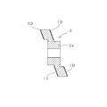
- FIG. 1 is a longitudinal sectional view showing an example of a swash plate compressor of the present invention.
- the swash plate type compressor shown in FIG. 1 uses carbon dioxide gas as a refrigerant.
- the swash plate 3 attached obliquely so as to be directly fixed to the rotary shaft 2 in the housing 1 in which the refrigerant exists is inclined.
- the reciprocating motion of the double-headed piston 5 is converted through the shoes 4 that slide on both sides of the plate 3, and the refrigerant is supplied to both sides of each piston 5 in the cylinder bore 6 formed at equal intervals in the circumferential direction of the housing 1.
- a swash plate type that compresses and expands.
- the rotary shaft 2 that is rotationally driven at high speed is supported by a needle roller bearing 7 in the radial direction and supported by a thrust needle roller bearing 8 in the thrust direction.
- the swash plate 3 may be fixed to the rotary shaft 2 indirectly via a connecting member. Moreover, the aspect attached rather than diagonally may be sufficient.
- the main feature of the swash plate of the swash plate compressor of the present invention is that a predetermined resin film is formed on the sliding surface with the shoe, so that it can be applied to any swash plate compressor of any of these modes.
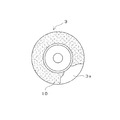
- Each piston 5 is formed with a recess 5a so as to straddle the outer periphery of the swash plate 3, and a hemispherical shoe 4 is seated on a spherical seat 9 formed on the axially opposed surface of the recess 5a. 5 is supported so as to be movable relative to the rotation of the swash plate 3. Thereby, the conversion from the rotational movement of the swash plate 3 to the reciprocating movement of the piston 5 is performed smoothly. If necessary, the surface of the shoe 4 may be subjected to processing for improving sliding characteristics such as nickel plating.
- the material of the base material 3a of the swash plate 3 is not particularly limited.
- a SAPH steel plate such as SAPH 440
- the base material 3a is formed by pressing a metal material into a disk shape to form a disk-shaped steel plate, and both surfaces thereof are finished into a swash plate shape by only turning, and the polishing process is omitted.
- the flat portions of both surfaces of the base material 3a of the swash plate 3 become sliding surfaces on which the shoes 4 slide.
- the base part 3a of the swash plate 3 which is a base (turning finished surface) immediately below the resin coating.
- shot blasting on the base part 3a of the swash plate 3 which is a base (turning finished surface) immediately below the resin coating.
- the sliding surface of the base plate 3a of the swash plate 3 with the shoe i.e., the flat portions (turning finished surfaces) of both surfaces of the base plate 3a has at least fluorine on the matrix resin.
- a resin film 10 containing resin powder and graphite is formed.
- the resin coating 10 is characterized by containing 25 to 70 parts by weight of a predetermined fluororesin powder and 1 to 20 parts by weight of graphite with respect to 100 parts by weight of the matrix resin.
- the tensile shear bond strength (according to JIS K6850) is 30 MPa or more.
- the resin film can be used without peeling even when the surface pressure received by the swash plate is 10 MPa or more, low friction characteristics, wear resistance characteristics, coating adhesion strength, and The cavitation resistance in the presence of lubricating oil can be satisfied in a well-balanced manner.
- the matrix resin should be a heat-resistant resin that has heat resistance that does not cause thermal degradation when the swash plate is used, and that can bind the fluororesin powder and firmly adhere the resin coating to the swash plate substrate. Can be used.
- the matrix resin include polyphenylene sulfide resin, polyether ether ketone resin, polyimide resin, polyamide resin, PAI resin, epoxy resin, and phenol resin. Among these, it is preferable to use a PAI resin because of excellent heat resistance, wear resistance, and adhesion to a swash plate substrate.
- the PAI resin is a resin having an imide bond and an amide bond in the polymer main chain.
- an aromatic PAI resin in which an imide bond and an amide bond are bonded via an aromatic group is preferable.
- the imide bond of the aromatic PAI resin may be a precursor such as polyamic acid, a closed imide ring, or a state in which they are mixed.
- aromatic PAI resins include PAI resins produced from aromatic primary diamines such as diphenylmethanediamine and aromatic tribasic acid anhydrides, such as mono- or diacyl halide derivatives of trimellitic acid anhydride, aromatic There are PAI resins produced from tribasic acid anhydrides and aromatic diisocyanate compounds such as diphenylmethane diisocyanate. Furthermore, as a PAI resin having a larger ratio of imide bonds than amide bonds, it is produced from aromatic, aliphatic or alicyclic diisocyanate compounds and aromatic tetrabasic acid dianhydrides and aromatic tribasic acid anhydrides. Any PAI resin can be used.
- Any fluororesin powder can be used as long as it is in the form of a fluororesin powder that has low friction and can impart non-adhesiveness to the resin film and has heat resistance that can withstand the operating temperature atmosphere of the swash plate.
- the fluororesin include PTFE resin, tetrafluoroethylene-perfluoroalkyl vinyl ether (PFA) copolymer resin, tetrafluoroethylene-hexafluoropropylene (FEP) copolymer resin, and tetrafluoroethylene-ethylene (ETFE) copolymer.
- PFA tetrafluoroethylene-perfluoroalkyl vinyl ether
- FEP tetrafluoroethylene-hexafluoropropylene copolymer resin
- ETFE tetrafluoroethylene-ethylene copolymer.
- Polymer resin etc. are mentioned. Among these, it is preferable to use PTFE resin powder.
- PTFE resin has a high melt viscosity of about 10 10 to 10 11 Pa ⁇ s at about 340 to 380 ° C., hardly flows even when the melting point is exceeded, has the highest heat resistance among fluororesins, and is excellent even at low temperatures It exhibits properties and excellent friction and wear characteristics.
- a general PTFE resin represented by — (CF 2 —CF 2 ) n— can be used, and a perfluoroalkyl ether group (—C p F 2p —O— is added to the general PTFE resin.
- P is an integer of 1-4
- These PTFE resins and modified PTFE resins may be obtained by employing either a suspension polymerization method for obtaining a general molding powder or an emulsion polymerization method for obtaining a fine powder.
- the maximum particle size of fluororesin powder such as PTFE resin powder is 16 ⁇ m or less.
- the maximum particle diameter exceeds 16 ⁇ m, a large stress concentration occurs at the interface between the matrix resin and the fluororesin powder. Since the fluororesin (particularly PTFE resin) has poor adhesion to other materials, cracks are likely to occur from this interface and cause peeling. Further, when the fluororesin powder overlaps in the swash plate axis direction, there may be a portion where the matrix resin does not exist from the base material to the surface, thereby reducing the adhesion strength of the coating.
- the 50% particle diameter of fluororesin powder such as PTFE resin powder is 3 to 5 ⁇ m.
- the fluororesin powder can be uniformly dispersed in the matrix resin, the stress concentration can be relaxed, and the adhesion strength of the coating can be improved.
- the 50% particle size is less than 3 ⁇ m, the cohesiveness is increased and it may be difficult to uniformly disperse in the solvent.
- the “50% particle size” is determined when the particle size of the powder and its distribution (particle size distribution) are measured using a known particle size distribution (particle size distribution) are measured using a known particle size distribution measuring device (for example, laser diffraction particle size distribution measuring device). This is the particle diameter when the frequency (%) of the particle diameter is accumulated from the smaller particle diameter side and the accumulated value is 50%.
- the polishing of the substrate is omitted, and the flatness of the substrate is inferior. Therefore, in order to obtain a sufficient limit surface pressure and the like, the maximum particle size in the fluororesin powder in the resin film It is important that the 50% particle diameter is within the above range.
- PTFE resin powder a PTFE resin obtained by heating and baking at a melting point or higher can be used. Further, a powder obtained by further irradiating a heat-fired powder with ⁇ rays or electron beams can also be used. These PTFE resin powders are more excellent in uniform dispersibility in the resin coating that forms the resin film than PTFE resins (molding powder, fine powder) that are not heated and fired, and the resistance of the formed resin film. Excellent wear characteristics.
- Fluorine resin powder such as PTFE resin powder is blended in an amount of 25 to 70 parts by weight with respect to 100 parts by weight of the matrix resin in the resin coating.
- the blending amount of the fluororesin powder is less than 25 parts by weight, the low friction characteristic is deteriorated, and there is a possibility that wear promotion due to heat generation occurs. In addition, workability during coating is also deteriorated.
- the blending amount of the fluororesin powder exceeds 70 parts by weight, the low friction characteristics are excellent, but the coating strength and wear resistance are deteriorated, and abnormal wear may occur under extreme pressure when the sliding shoe comes into contact with one piece. There is.
- the blending amount of the fluororesin is 65 parts by weight or less, the tensile shear adhesive strength exceeds 35 MPa, and a sufficient safety factor against the extreme pressure conditions due to the per side of the sliding shoe piece can be sufficiently secured.
- the amount of the fluororesin powder exceeds 70 parts by weight with respect to 100 parts by weight of the matrix resin when it exceeds about 40% by weight when converted to the content of the fluororesin powder in the resin film. is there.
- graphite has excellent properties as a solid lubricant, and is also used as a solid lubricant for swash plates.
- Graphite is roughly classified into natural graphite and artificial graphite. The shape includes flakes, granules, and spheres, but any of them can be used.
- graphite graphite having 97.5% or more of fixed carbon is preferably used, and artificial graphite having 98.5% or more of fixed carbon is more preferable.
- Such graphite has high compatibility with the lubricating oil, and even if the lubricating oil does not adhere to the surface, the lubricating property is maintained by the lubricating oil impregnated in a trace amount in the graphite.
- Graphite is blended in an amount of 1 to 20 parts by weight with respect to 100 parts by weight of the matrix resin in the resin coating for the purpose of improving the friction and wear characteristics.
- the amount of graphite is less than 1 part by weight, the effect of improving the friction and wear characteristics when graphite is blended is not recognized.
- the blending amount of graphite exceeds 20 parts by weight, the adhesion of the film may be impaired, and peeling may occur.
- the total amount of additives such as fluororesin powder and graphite with respect to the matrix resin is less than 15 parts by weight, unevenness occurs in the resin film, and it becomes difficult to obtain the required dimensional accuracy.
- the resin film may contain other additives in addition to the matrix resin, fluororesin powder, and graphite as long as the necessary characteristics of the swash plate of the present invention are not significantly reduced.
- the strength, the low friction characteristic, the wear resistance characteristic, and the cavitation resistance can be obtained in a most balanced manner when it is formed substantially by three components of matrix resin, fluororesin powder and graphite.
- the matrix resin is PAI resin
- the fluororesin powder is PTFE resin powder
- the graphite is graphite with fixed carbon of 97.5% or more. Yes, leading to cost reduction of the swash plate.
- the resin film is required to have cavitation resistance so that erosion due to cavitation does not occur.
- the manufacturing method of the swash plate of the swash plate compressor of the present invention is as follows. (1) After pressing a metal material into a disk shape, both surfaces thereof are finished into a swash plate shape only by turning and used as a base material for the swash plate. A material turning step; and (2) a resin film forming step of forming the above-described resin film on the finished surface of the base material, which is a sliding surface with the shoe, using a resin paint.
- a shot blasting process for performing shot blasting on the base layer immediately below the resin coating of the base material, and a resin coating after the process (2) It is preferable to include a resin polishing step in which the surface of the substrate is polished by a double-head polishing machine.
- a preferable manufacturing process is as follows. (1) As a substrate turning process, after pressing a metal material into a disk shape, both surfaces thereof are finished into a swash plate shape only by turning. Thereafter, a shot blasting process is performed on the resin film forming portion in order to improve the adhesion of the resin film. (2) As the resin film forming step, the shot blast surface is coated on both sides by spraying, the solvent in the coating solution is volatilized, and preliminary drying and main baking are performed in order to cure and adhere. (3) As a resin polishing step, the surface of the resin coating is polished with a double-head polishing machine and finished to a predetermined dimensional accuracy.
- Substrate turning step it is preferable that both surfaces of the substrate, which is the finished surface of the turning process, have a flatness of 0.012 mm or less and a parallelism of both surfaces of 0.012 mm or less. Thereby, the dispersion
- the arithmetic average roughness Ra on each surface is 1.5 ⁇ m or less.
- Resin film formation process This process is a process of forming a resin film by spray coating using a resin paint. Roll coating or the like is also possible.
- the resin coating is obtained by dispersing or dissolving solid matrix resin, fluororesin powder and graphite in the above-mentioned blending ratio in solvents.
- Solvents include ketones such as acetone and methyl ethyl ketone, esters such as methyl acetate and ethyl acetate, aromatic hydrocarbons such as toluene and xylene, and organic halogenated compounds such as methyl chloroform, trichloroethylene, and trichlorotrifluoroethane.
- Aprotic polar solvents such as N-methyl-2-pyrrolidone (NMP), methylisopyrrolidone (MIP), dimethylformamide (DMF), and dimethylacetamide (DMAC) can be used. These solvents can be used alone or as a mixture.
- preliminary drying and main baking are performed.
- a drying process 100 degreeC or more and 150 degrees C or less are preferable, and as a baking process, 200 degreeC or more and less than 250 degreeC are preferable.
- the drying step 100 ° C. or more and 150 ° C. or less, it is possible to effectively volatilize the solvents contained in the resin coating without curing the resin, and to suppress the foaming phenomenon in the firing step.
- the baking step to 200 ° C. or higher and lower than 250 ° C., the resin film is cured without being thermally decomposed, and a strong film can be obtained.
- the resin coating obtained in the resin coating forming step is preferably 20 to 50 ⁇ m in thickness after firing.
- This resin film having a film thickness of 20 to 50 ⁇ m is preferably processed into a film thickness of 8 to 30 ⁇ m by a double-head polishing machine so that the final finishing accuracy, flatness is 0.015 mm or less, and parallelism is 0.015 mm or less. Since the resin film is polished (finished) by a double-head polishing machine, the parallelism of both surfaces of the swash plate sliding surface can be processed with high accuracy.
- the arithmetic average roughness Ra of the surface of the resin coating can be changed by the number of the grinding wheel, and is preferably 0.1 to 0.9 ⁇ m. If the surface roughness is less than 0.1 ⁇ mRa, the supply of lubricating oil to the sliding surface will be insufficient, and if it exceeds 0.9 ⁇ mRa, the surface area will be locally high due to a decrease in the real contact area on the sliding surface, and seizure will occur. There is concern about the occurrence of More preferably, it is 0.2 to 0.8 ⁇ mRa.
- the swash plate type compressor of the present invention is provided with the swash plate as described above, it is inexpensive such as when the small-diameter shoe is in a locally contacted state or when the surface is not specially processed. Excellent seizure resistance even when using shoes or when lubricating oil is exhausted. Further, the coating can be prevented from being eroded by cavitation in the presence of lubricating oil at high surface pressure and high speed. Further, the polishing of the base material in the swash plate can be omitted, so that the cost can be reduced.
- the solid contents of the resin coatings used in the examples and comparative examples are as follows.
- a PAI resin varnish in which a PAI resin was dispersed in N-methylpyrrolidone was used, and this was mixed with a PTFE resin powder and a graphite powder and diluted.
- PTFE resin powder PTFE resin (heated and fired material, particle diameter, etc. are described in each table)
- PAI resin Glass transition temperature 245 ° C.
- Graphite powder Artificial graphite (average particle size 10 ⁇ m)
- Examples 1 to 5 After forming the SAPH440 steel plate into a disk shape by press working, thickness 6.36 mm ⁇ diameter ⁇ 90 mm, surface roughness of both surfaces 1.5 ⁇ mRa or less, flatness 0.012 mm or less, parallelism 0.012 mm or less Lathe processing was performed. Next, shot blasting (targeted at Rz 5.0 ⁇ m) was performed on the turning surface of the disk substrate to increase the surface roughness. Furthermore, the resin paint having a solid content shown in Table 1 was applied to both surfaces of the disk substrate shot blasted by spray coating so that it would be 30 ⁇ m after firing, and after preliminary drying at 100 ° C., 240 Baked at °C.
- both surfaces are polished by a double-head polishing machine (grinding stone: for resin # 400) and final finishing (flatness: 0.015 mm or less, parallelism: 0.015 mm or less, thickness 6.40 mm, surface roughness 0) 0.6-0.7 ⁇ m Ra) was performed to obtain a test piece.
- Comparative Examples 1 to 7 The substrate of the comparative example was processed in the same manner as in Example 1. Next, after applying the resin coating having a solid content of Table 2 on the both surfaces of the disk substrate shot blasted by spray coating method so as to be 30 ⁇ m after firing, preliminarily drying at 100 ° C., Baked at 240 ° C. Thereafter, both surfaces are polished by a flat polishing machine (grinding stone: for resin # 400) and final finishing (flatness: 0.015 mm or less, parallelism: 0.015 mm or less, thickness 6.40 mm, surface roughness 0) 0.6-0.7 ⁇ m Ra) was performed to obtain a test piece.
- a flat polishing machine grinding stone: for resin # 400
- final finishing flatness: 0.015 mm or less, parallelism: 0.015 mm or less, thickness 6.40 mm, surface roughness 0
- Example 6 and Comparative Example 8 The SAPH440 steel plate was formed into a disk shape by press working, and then roughed with a lathe with a thickness of 6.5 mm and a diameter of ⁇ 90 mm. Thereafter, both surfaces were polished by a double-head polishing machine (grinding stone: # 80) so that the flatness was 0.005 mm or less, the parallelism was 0.005 mm or less, and the thickness was 6.36 mm. Next, shot blasting (targeted at Rz 5.0 ⁇ m) was performed on the polished surface of the disk substrate to increase the surface roughness. In the subsequent steps, test pieces were obtained in the same manner as in other examples or comparative examples.
- Friction and wear test using a thrust type tester (3 shoe-on-type) that slides three steel shoes (SUJ2, ⁇ 13 mm (effective sliding part)) for each test piece of Example and Comparative Example And the coefficient of friction after 60 minutes was measured.
- the test conditions are as follows. Load: 400N Sliding speed: 32m / min Lubrication condition: Dry Test time: 60 minutes
- Cavitation resistance was evaluated by a cavitation test / opposite type.
- the test conditions are as follows. A flat plate with a resin coating on the surface is set in water, a vibrator is set immediately above, and the vibrator is deliberately generated cavitation, attacking the resin coating for durability. evaluated. The state of the resin coating after the test was confirmed visually and with a needle-touch type shape measuring instrument, and “ ⁇ ” was observed only for minute erosion that was not affected by discoloration or the like, and there was erosion at a depth of 10 ⁇ m or more. Each was recorded as an “x”. Frequency: 18 kHz Test time: 10min Test environment: Underwater (room temperature)
- each example has a stable coefficient of friction from the beginning of the test to 60 minutes later, ensuring a balance between the critical surface pressure (wear characteristics), the adhesion strength of the coating, and the resistance to cavitation. Has been.
- Example 2 has been confirmed to reduce friction and improve the cohesive strength within the film, so that the overall balance is better.
- Example 2 is the same result as Example 6, and has confirmed that a difference was not recognized by the test result by the presence or absence of the grinding
- Comparative Example 1 was excellent in tensile shear adhesive strength and limit surface pressure, but had a high coefficient of friction. In Comparative Examples 2 and 3, although the friction coefficient was excellent, the tensile shear bond strength and the limit surface pressure were low. In Comparative Examples 4 to 8, although the tensile shear bond strength was excellent, the limit surface pressure was lower than that of the Examples.
- the swash plate according to the present invention has a sufficient balance of low friction characteristics, wear resistance characteristics, coating adhesion strength, and cavitation resistance, and is resistant to extreme pressures such as per piece of sliding shoe. It was found that it has excellent wear characteristics and seizure resistance under conditions where the refrigerator oil is exhausted. Furthermore, since the limit surface pressure was higher than 10 MPa, it was found that the carbon dioxide gas whose pressure in the compressor reached 10 MPa was sufficiently usable even when used in a swash plate type compressor using a refrigerant.
- the swash plate of the present invention is more economical (lower cost) than the conventional product, and in the operation of the swash plate compressor, the extreme pressure conditions such as per piece of the sliding shoe and the refrigerating machine oil are depleted. It was confirmed that this is an effective measure for obtaining a stable boundary lubrication state even under such conditions.
- the solid content of the resin paint in this test is as follows.
- a PAI resin varnish in which a PAI resin was dispersed in N-methylpyrrolidone was used, and this was mixed with a PTFE resin powder and a graphite powder and diluted.
- PTFE resin powder PTFE resin (maximum particle diameter of 16 ⁇ m or less, 50% particle diameter of 3 to 5 ⁇ m, heat-fired material)
- PAI resin Glass transition temperature 245 ° C.
- Graphite powder Artificial graphite (average particle size 10 ⁇ m)
- Production Example 1 to Production Example 4 After forming the SAPH440 steel plate into a disk shape by pressing, the thickness is 6.36 mm ⁇ diameter ⁇ 90 mm, the surface roughness of both surfaces is 1.75 ⁇ mRa or less, the flatness is 0.015 mm or less, and the parallelism is 0.015 mm or less. Lathe processing was performed. Next, Production Example 2 was a double-head polishing machine (grinding stone: # 80), and both surfaces were polished so that the flatness was 0.005 ⁇ m or less, the parallelism was 0.005 ⁇ m or less, and the thickness was 6.36 mm.
- Shot blasting (targeted at Rz 5.0 ⁇ m) was performed on the turning surface and the polished surface of the disk substrate to increase the surface roughness. Further, the resin coating material of Example 2 was applied as a solid content on both surfaces of the disk substrate shot blasted by spray coating so as to be 30 ⁇ m after firing, dried at 100 ° C., and fired at 240 ° C. Thereafter, both surfaces are polished by a double-head polishing machine (grinding stone: for resin # 400) and final finishing (flatness: 0.015 mm or less, parallelism: 0.015 mm or less, thickness 6.40 mm, surface roughness 0) 0.6-0.7 ⁇ m Ra) was performed to obtain a test piece. About the obtained test piece, the above-mentioned limit surface pressure test was implemented on the same conditions.
- the swash plate of the swash plate compressor according to the present invention can satisfy a good balance of low friction characteristics, wear resistance characteristics, coating adhesion strength, cavitation resistance, and economic efficiency. It can also be suitably used for some recent swash plate compressors.
Landscapes
- Engineering & Computer Science (AREA)
- Mechanical Engineering (AREA)
- General Engineering & Computer Science (AREA)
- Compressors, Vaccum Pumps And Other Relevant Systems (AREA)
Abstract
製造時におけるコストアップやスラッジの発生を防止でき、摺接するシューの片当たりによる極圧下での条件や潤滑油が枯渇するような条件での耐焼き付き性に優れ、かつ、高面圧・高速で潤滑油存在下においてキャビテーションによる被膜の壊食を防止できる斜板式コンプレッサの斜板、およびその製造方法、並びに該斜板を備えた斜板式コンプレッサを提供する。斜板式コンプレッサの斜板3であり、シューとの摺動面となる該斜板の基材3aの両表面に、マトリックス樹脂100重量部にフッ素樹脂粉末を25~70重量部、黒鉛を1~20重量部含む樹脂被膜10が形成されており、このフッ素樹脂粉末は、最大粒子径が16μm以下であり50%粒子径が3~5μmである。
Description
本発明はエアコンディショナなどに用いられる斜板式コンプレッサの斜板およびその製造方法、さらに該斜板を備えた斜板式コンプレッサに関する。
斜板式コンプレッサは、冷媒が存在するハウジング内で、回転軸に直接固定するように、または連結部材を介して間接的に、直角または斜めに取り付けた斜板にシューを摺動させ、このシューを介して斜板の回転運動をピストンの往復運動に変換して、冷媒を圧縮、膨張させるものである。このような斜板式コンプレッサには、両頭形のピストンを用いて冷媒を両側で圧縮、膨張させる両斜板タイプのものと、片頭形のピストンを用いて冷媒を片側のみで圧縮、膨張させる片斜板タイプのものとがある。また、シューは斜板の片側面のみで摺動するものと、斜板の両側面で摺動するものとがある。
これらの斜板式コンプレッサでは、運転初期において、冷媒が存在するハウジング内へ潤滑油が到達する前に金属製の斜板とシューが摺動する場合があるため、これらの摺動部が潤滑油のないドライ潤滑状態となり、焼付きが発生しやすい。特に、近年開発が行なわれている炭酸ガスを冷媒に用いる斜板式コンプレッサでは、コンプレッサ内の圧力が8~10MPaにも達するため、斜板とシューとの摺動圧力もこれまでより高くなり、斜板の摺動部にはこれまで以上に焼付きが発生しやすくなるという問題がある。
この焼付きを防止する手段として、耐焼付き性に優れ、炭酸ガスを冷媒に用いる斜板式コンプレッサにも耐用可能なものとして、圧延された鋼板を円盤状にプレス加工した斜板基板の両表面を、研磨加工してシューが摺動する摺動面とし、この摺動面にフッ素樹脂が40~50重量%配合された低摩擦樹脂被覆層を形成した斜板式コンプレッサの斜板が提案されている(特許文献1参照)。
また、さらに耐久性を向上させるために、圧延された鋼板を円盤状にプレス加工した斜板基板の両表面を、研磨加工してシューが摺動する摺動面とし、この摺動面に、マトリックス樹脂100重量部に対してフッ素樹脂を25~70重量部、黒鉛を1~20重量部含み、引張せん断接着強さが25MPa以上である低摩擦樹脂被覆層を形成した斜板式コンプレッサの斜板が提案されている(特許文献2参照)。
特許文献1や特許文献2のように、従来、斜板基材に研磨加工を施した後、ショットブラスト工程へ進んでいた。これは、基材厚みの寸法および幾何公差を高精度化することで、コーティング膜厚のばらつきを抑え、コーティング膜の薄膜化が図れるためである。しかし、斜板基材の表面を研磨加工することは、コストアップやスラッジの発生による地球環境負荷の増大などの懸念がある。
また、自家用自動車のエアコンディショナ(エアコン)用として搭載される斜板式コンプレッサにおいては、近年において、さらなる省エネ化や軽量コンパクト化を求められており、シューの小径化によって斜板に局所的にシューが当接し、焼き付きを発生させるおそれがある。また、電気系自動車への対応もあり、電動化に伴う低摩擦化も強く要望されるものの、低摩擦特性、耐摩耗特性、斜板などに形成する被膜の密着強度のバランスを満足することは容易ではない。
さらに、軽量コンパクト化により斜板が小型化し、より高速高負荷仕様へと変更されてきている。斜板が高面圧、高速で摺動する場合、潤滑油中にキャビテーション(発生した気泡の破裂による衝撃性)が発生し易い環境となるため、摺動被膜が壊食しないよう耐キャビテーション性を有するものでなければならない。
本発明はこれらの問題に対処するためになされたものであり、製造時におけるコストアップやスラッジの発生を防止でき、摺接するシューの片当たりによる極圧下での条件や潤滑油が枯渇するような条件での耐焼き付き性に優れ、かつ、高面圧・高速で潤滑油存在下においてキャビテーションによる被膜の壊食を防止でき、低摩擦特性、耐摩耗特性、被膜の密着強度、および経済性をバランスよく満足できる斜板式コンプレッサの斜板、およびその製造方法、並びに該斜板を備えた斜板式コンプレッサを提供することを目的とする。
本発明の斜板式コンプレッサの斜板は、冷媒が存在するハウジング内で、回転軸に直接固定するように、または連結部材を介して間接的に、直角または斜めに取り付けた斜板にシューを摺動させ、このシューを介して上記斜板の回転運動をピストンの往復運動に変換して、冷媒を圧縮、膨張させる斜板式コンプレッサの斜板であって、上記斜板は、上記シューとの摺動面となる該斜板の基材の両表面に、マトリックス樹脂100重量部に対して、少なくともフッ素樹脂粉末を25~70重量部、黒鉛を1~20重量部含む樹脂被膜が形成されており、上記フッ素樹脂粉末は、最大粒子径が16μm以下であり、50%粒子径が3~5μmであることを特徴とする。また、上記斜板は、上記シューとの摺動面となる該斜板の基材の両表面を研磨不要とすることができ、特に、上記斜板の基材の両表面が旋削加工仕上げ面であることを特徴とする。
上記樹脂被膜の引張せん断接着強さ(JIS K6850準拠)が30MPa以上であることを特徴とする。
上記基材の両表面は、平面度が0.012mm以下であり、両表面の平行度が0.012mm以下であることを特徴とする。
上記マトリックス樹脂が、ポリアミドイミド(PAI)樹脂であり、上記フッ素樹脂がポリテトラフルオロエチレン(PTFE)樹脂であり、上記黒鉛が固定炭素97.5%以上の黒鉛であることを特徴とする。
上記基材の両表面に形成された上記樹脂被膜の表面は、それぞれの面における平面度が0.015mm以下であり、両表面の平行度が0.015mm以下であることを特徴とする。また、上記樹脂被膜の表面の算術平均粗さRaは、0.1~0.9μmであることを特徴とする。なお、本発明において「平面度」と「平行度」は、JIS B0182で定義されるものであり、「算術平均粗さRa」は、JIS B0601で定義されるものである。
本発明の斜板式コンプレッサの斜板の製造方法は、冷媒が存在するハウジング内で、回転軸に直接固定するように、または連結部材を介して間接的に、直角または斜めに取り付けた斜板にシューを摺動させ、このシューを介して上記斜板の回転運動をピストンの往復運動に変換して、冷媒を圧縮、膨張させる斜板式コンプレッサの斜板の製造方法であって、金属素材を円盤状にプレス加工した後、その両表面を旋削加工のみで斜板形状に仕上げて上記斜板の基材とする基材旋削工程と、上記基材において、上記シューとの摺動面となる旋削加工仕上げ面に、樹脂塗料を用いて樹脂被膜を形成する樹脂被膜形成工程とを有し、上記樹脂塗料は、マトリックス樹脂100重量部に対して、少なくともフッ素樹脂粉末を25~70重量部、黒鉛を1~20重量部含み、上記フッ素樹脂粉末は、最大粒子径が16μm以下であり、50%粒子径が3~5μmであることを特徴とする。
上記基材旋削工程は、上記基材の両表面を、平面度が0.012mm以下であり、両表面の平行度が0.012mm以下となるように旋削加工を施す工程であることを特徴とする。
上記基材旋削工程後、上記樹脂被膜形成工程前において、上記基材の上記樹脂被膜直下の下地となる部分にショットブラスト処理を施すことを特徴とする。
上記樹脂被膜形成工程後において、上記樹脂被膜の表面を両頭研磨機によって研磨加工することを特徴とする。
本発明の斜板式コンプレッサは、冷媒が存在するハウジング内で、回転軸に直接固定するように、または連結部材を介して間接的に、直角または斜めに取り付けた斜板にシューを摺動させ、このシューを介して上記斜板の回転運動をピストンの往復運動に変換して、冷媒を圧縮、膨張させる斜板式コンプレッサであって、上記斜板として本発明の斜板を用いることを特徴とする。
本発明の斜板式コンプレッサの斜板は、シューとの摺動面となる基材の両表面に、マトリックス樹脂100重量部に対して、少なくともフッ素樹脂粉末を25~70重量部、黒鉛を1~20重量部含む樹脂被膜が形成されており、特にこのフッ素樹脂粉末が最大粒子径16μm以下かつ50%粒子径3~5μmであるので、基材表面を旋削加工仕上げとする場合でも、樹脂被膜の低摩擦特性と耐摩耗特性に優れ、かつ、該樹脂被膜の引張せん断接着強さが高く(例えば30MPa以上)、斜板基材との被膜の密着強度も高くなる。このため、斜板が受ける面圧が10MPa以上の斜板式コンプレッサにも樹脂被膜が剥がれることなく使用できる。さらに、耐キャビテーション性に優れ、潤滑油存在下でのキャビテーションによる樹脂被膜の壊食を防止することができる。また、基材表面を旋削加工仕上げとして研磨加工の省略が可能であり、製造時におけるコストアップやスラッジの発生を防止することができる。
基材の両表面は、平面度が0.012mm以下であり、両表面の平行度が0.012mm以下であるので、樹脂被膜の膜厚のばらつきを抑制でき、基材露出による焼き付きを防止することができる。
マトリックス樹脂がPAI樹脂であるので、耐熱性、耐摩耗特性および斜板基材との密着性に優れる。また、フッ素樹脂がPTFE樹脂であり、黒鉛が固定炭素97.5%以上の黒鉛であるので、入手が容易であるとともに比較的安価であり、斜板のコストダウンに繋がる。
基材の両表面に形成された樹脂被膜の表面は、それぞれの面における平面度が0.015mm以下であり、両表面の平行度が0.015mm以下であるので、斜板摺動面の両面の平面度と平行度に優れる。また、樹脂被膜の表面の算術平均粗さRaが、0.1~0.9μmであるので、シューと摺動する樹脂被膜摺動面における真実接触面積が大きくなり、実面圧を下げることができる。そのため、焼き付きを防止することができる。
本発明の斜板式コンプレッサの斜板の製造方法は、金属素材を円盤状にプレス加工した後、その両表面を旋削加工のみで斜板形状に仕上げて斜板の基材とする基材旋削工程と、この基材において、シューとの摺動面となる旋削加工仕上げ面に、所定の樹脂塗料を用いて樹脂被膜を形成する樹脂被膜形成工程とを有するので、基材を旋削加工仕上げとして研磨工程を省略でき、大幅なリードタイムの短縮およびコストダウンに繋がる。また、研磨加工によるスラッジの発生も防止することができる。
基材旋削工程が、基材の両表面を、平面度が0.012mm以下であり、両表面の平行度が0.012mm以下となるように旋削加工を施す工程であるので、樹脂被膜の膜厚のばらつきを抑制でき、基材露出による焼き付きを防止することができる。
基材旋削工程後、樹脂被膜形成工程前において、基材の樹脂被膜直下の下地となる部分にショットブラスト処理を施すので、金属溶射層などの中間層を設けなくとも樹脂被膜との密着強度に優れる。
樹脂被膜形成工程後において、樹脂被膜の表面を両頭研磨機によって研磨加工するので、斜板摺動面の両面の平行度を精度よく加工することができ、実面圧を下げることができる。そのため、焼き付きを防止することができる。
本発明の斜板式コンプレッサは、上述した斜板を備えたものであるので、小径のシューが局所的に当接した状態となる場合や、表面が特殊加工していないSUJ2などの安価なシューを使用した場合、潤滑油が枯渇するような場合でも、耐焼き付き性に優れ、斜板の焼き付きに起因したトラブルを回避可能であり、安心、長寿命な斜板式コンプレッサとなる。また、高面圧仕様にも使用可能であるため、炭酸ガスあるいはHFC1234yfを冷媒に用いたものに好適である。
本発明の斜板式コンプレッサの一実施例を図面に基づき説明する。図1は、本発明の斜板式コンプレッサの一例を示す縦断面図である。図1に示す斜板式コンプレッサは、炭酸ガスを冷媒に用いるものであり、冷媒が存在するハウジング1内で、回転軸2に直接固定するように斜めに取り付けた斜板3の回転運動を、斜板3の両側面で摺動するシュー4を介して両頭形ピストン5の往復運動に変換し、ハウジング1の周方向に等間隔で形成されたシリンダボア6内の各ピストン5の両側で、冷媒を圧縮、膨張させる両斜板タイプのものである。高速で回転駆動される回転軸2は、ラジアル方向を針状ころ軸受7で支持され、スラスト方向をスラスト針状ころ軸受8で支持されている。
斜板3は、連結部材を介して間接的に回転軸2に固定される態様でもよい。また、斜めではなく直角に取り付けられる態様であってもよい。本発明の斜板式コンプレッサの斜板の主な特徴は、シューとの摺動面に所定の樹脂被膜を形成する点にあるので、これらいずれの態様の斜板式コンプレッサについても適用可能である。
各ピストン5には斜板3の外周部を跨ぐように凹部5aが形成され、この凹部5aの軸方向対向面に形成された球面座9に、半球状のシュー4が着座されており、ピストン5を斜板3の回転に対して相対移動自在に支持する。これによって、斜板3の回転運動からピストン5の往復運動への変換が円滑に行われる。また、必要に応じて、シュー4の表面は、ニッケルめっきなどの摺動特性改善のための加工が施されていてもよい。
斜板3の基材3aの材質としては、特に限定されない。例えば、SAPH440等のSAPH鋼板とすることで、機械的強度に優れプレス加工が可能で斜板の製造が簡略化可能となり、コストダウンに繋がる。基材3aは、金属素材を円盤状にプレス加工して円盤状鋼板とし、その両表面を旋削加工のみで斜板形状に仕上げ、研磨加工を省略している。斜板3の基材3aにおける両表面の平面部が、シュー4が摺動する摺動面となる。
また、斜板3の基材3aにおいて、樹脂被膜直下の下地となる部分(旋削加工仕上げ面)にショットブラスト処理を施すことが好ましい。これにより、金属溶射層などの中間層を設けなくとも樹脂被膜との密着強度に優れ、剥がれも少なくなる。また、溶射層を形成しないことで、コストダウンに繋がり、斜板の平面精度の低下も防止することができる。
図2および図3に示すように、斜板3の基材3aにおけるシューとの摺動面、すなわち、基材3aの両表面の平面部(旋削加工仕上げ面)には、マトリックス樹脂に少なくともフッ素樹脂粉末と黒鉛とを含む樹脂被膜10が形成されている。本発明では、この樹脂被膜10が、マトリックス樹脂100重量部に対して、所定のフッ素樹脂粉末を25~70重量部、黒鉛を1~20重量部含むことを特徴としている。特に、引張せん断接着強さ(JIS K6850準拠)が30MPa以上である。斜板3にこのような樹脂被膜を形成することで、斜板が受ける面圧が10MPa以上の場合でも樹脂被膜が剥がれることなく使用でき、低摩擦特性、耐摩耗特性、被膜の密着強度、および、潤滑油存在下での耐キャビテーション性をバランスよく満足させることができる。
マトリックス樹脂としては、斜板の使用時に熱劣化することのない耐熱性を有し、フッ素樹脂粉末を結着させ、樹脂被膜を斜板基材に強固に密着させることのできる耐熱性樹脂であれば使用できる。マトリックス樹脂としては、例えば、ポリフェニレンサルファイド樹脂、ポリエーテルエーテルケトン樹脂、ポリイミド樹脂、ポリアミド樹脂、PAI樹脂、エポキシ樹脂、フェノール樹脂などが挙げられる。これらの中でも、耐熱性、耐摩耗特性および斜板基材との密着性に優れることから、PAI樹脂を用いることが好ましい。
PAI樹脂は、高分子主鎖内にイミド結合とアミド結合とを有する樹脂である。PAI樹脂の中でも、イミド結合、アミド結合が芳香族基を介して結合している芳香族系PAI樹脂が好ましい。芳香族系PAI樹脂であると、下地である斜板基材との結着性に優れ、かつ得られる樹脂被膜の耐熱性が特に優れる。ここで、芳香族系PAI樹脂のイミド結合は、ポリアミド酸などの前駆体であっても、また閉環したイミド環であってもよく、さらにはそれらが混在している状態であってもよい。
このような芳香族系PAI樹脂は、芳香族第一級ジアミン、例えばジフェニルメタンジアミンと芳香族三塩基酸無水物、例えばトリメリット酸無水物のモノまたはジアシルハライド誘導体から製造されるPAI樹脂、芳香族三塩基酸無水物と芳香族ジイソシアネート化合物、例えばジフェニルメタンジイソシアネートとから製造されるPAI樹脂などがある。さらに、アミド結合に比べてイミド結合の比率を大きくしたPAI樹脂として、芳香族、脂肪族または脂環族ジイソシアネート化合物と芳香族四塩基酸二無水物および芳香族三塩基酸無水物とから製造されるPAI樹脂などがあり、いずれのPAI樹脂であっても使用することができる。
フッ素樹脂粉末としては、低摩擦で非粘着性を樹脂被膜に付与でき、かつ斜板の使用温度雰囲気に耐える耐熱性を有するフッ素樹脂の粉末状のものであれば使用できる。フッ素樹脂としては、例えば、PTFE樹脂、テトラフルオロエチレン-パーフルオロアルキルビニルエーテル(PFA)共重合体樹脂、テトラフルオロエチレン-ヘキサフルオロプロピレン(FEP)共重合体樹脂、テトラフルオロエチレン-エチレン(ETFE)共重合体樹脂などが挙げられる。これらの中でも、PTFE樹脂の粉末を用いることが好ましい。PTFE樹脂は、約340~380℃の溶融粘度が約1010~1011Pa・sと高く、融点をこえても流動し難く、フッ素樹脂の中では最も耐熱性に優れ、低温下でも優れた性質を示し、摩擦摩耗特性にも優れる。
PTFE樹脂としては、-(CF2-CF2)n-で表される一般のPTFE樹脂を用いることができ、また、一般のPTFE樹脂にパーフルオロアルキルエーテル基(-CpF2p-O-)(pは1-4の整数)あるいはポリフルオロアルキル基(H(CF2)q-)(qは1-20の整数)などを導入した変性PTFE樹脂も使用できる。これらのPTFE樹脂および変性PTFE樹脂は、一般的なモールディングパウダーを得る懸濁重合法、ファインパウダーを得る乳化重合法のいずれを採用して得られたものでもよい。
PTFE樹脂粉末などのフッ素樹脂粉末の最大粒子径は16μm以下である。最大粒子径が16μmをこえると、マトリックス樹脂とフッ素樹脂粉末との界面に大きな応力集中が生じる。フッ素樹脂(特にPTFE樹脂)は他材料との密着性が悪いので、この界面からき裂が発生しやすくなり、剥がれの原因となる。また、斜板軸方向にフッ素樹脂粉末が重なると基材から表面にかけてマトリックス樹脂が存在しない箇所が存在する可能性があり、それによって被膜の密着強度が低下してしまう。
また、PTFE樹脂粉末などのフッ素樹脂粉末の50%粒子径は3~5μmである。これにより、マトリックス樹脂中に均質にフッ素樹脂粉末を分散することができ、また、応力集中を緩和することができ被膜の密着強度を向上することができる。50%粒子径が3μm未満であると、凝集性が高まり、溶剤中に均質に分散させることが困難になるおそれがある。なお、「50%粒子径」は、公知の粒度分布測定装置(例えば、レーザー回析式粒度分布測定装置)を用いて、この粉末の粒子径およびその分布(粒度分布)を測定した際に、粒子径の頻度(%)を粒子径が小さい側から累積し、累積値が50%である場合の粒子径である。
特に、本発明では基材の研磨加工を省略しており、基材の平面度などが劣るため、十分な限界面圧などを得るためには、樹脂被膜中の上記フッ素樹脂粉末において最大粒子径や50%粒子径を上記範囲にすることが重要となる。
PTFE樹脂粉末としては、PTFE樹脂をその融点以上で加熱焼成したものを使用できる。また、加熱焼成した粉末に、さらにγ線または電子線などを照射した粉末も使用できる。これらのPTFE樹脂粉末は、加熱焼成等されていないPTFE樹脂(モールディングパウダー、ファインパウダー)と比較して、樹脂被膜を形成する樹脂塗料中での均一分散性に優れ、形成された樹脂被膜の耐摩耗特性が優れる。
PTFE樹脂粉末などのフッ素樹脂粉末は、樹脂被膜においてマトリックス樹脂100重量部に対して25~70重量部配合される。フッ素樹脂粉末の配合量が25重量部未満であると、低摩擦特性が劣化し、発熱による摩耗促進が発生するおそれがある。また、コーティング時の作業性も悪化する。一方、フッ素樹脂粉末の配合量が70重量部をこえると低摩擦特性は優れるが、被膜強度および耐摩耗特性が劣化し、摺接するシューが片当たりした場合の極圧下においては異常摩耗を生じるおそれがある。特に、フッ素樹脂の配合量を65重量部以下にした場合、引張せん断接着強さは35MPaをこえ、摺接するシューの片あたりによる極圧下条件などへの安全率が十二分に確保できる。なお、マトリックス樹脂100重量部に対して、フッ素樹脂粉末の配合量が70重量部をこえるとは、樹脂被膜中に占めるフッ素樹脂粉末の含有量に換算すると約40重量%をこえるような場合である。
黒鉛は固体潤滑剤として優れた特性を有することは周知であり、斜板の固体潤滑剤としても使用されている。黒鉛は、天然黒鉛と人造黒鉛に大別される。また、形状としては、りん片状、粒状、球状などがあるが、いずれも使用できる。黒鉛としては、固定炭素97.5%以上の黒鉛の使用が好ましく、さらには、固定炭素98.5%以上の人造黒鉛が好ましい。このような黒鉛は、潤滑油とのなじみ性が高く、表面に潤滑油が付着していなくても黒鉛中に微量に含浸された潤滑油によって潤滑性が維持される。
黒鉛は、摩擦摩耗特性を改質する目的で、樹脂被膜においてマトリックス樹脂100重量部に対して1~20重量部配合される。黒鉛の配合量が1重量部未満であると黒鉛を配合した場合の摩擦摩耗特性の改質効果が認められない。一方、黒鉛の配合量が20重量部をこえると被膜の密着性を損ない、剥がれの原因となるおそれがある。なお、マトリックス樹脂に対するフッ素樹脂粉末や黒鉛などの添加剤の総量が15重量部より少ないと樹脂被膜にムラが発生し、所要の寸法精度を得ることが難しくなる。
樹脂被膜は、上記マトリックス樹脂、フッ素樹脂粉末、黒鉛の他に、本発明の斜板の必要特性を著しく低下させない範囲であれば他の添加剤を含んでも構わないが、樹脂被膜の引張せん断接着強さ、低摩擦特性、耐摩耗特性、耐キャビテーション性を最もバランスよく得ることができるのは、実質的にマトリックス樹脂とフッ素樹脂粉末と黒鉛との3成分によって形成される場合である。
また、樹脂被膜において、マトリックス樹脂をPAI樹脂とし、フッ素樹脂粉末をPTFE樹脂粉末とし、黒鉛を固定炭素97.5%以上の黒鉛とすることで、それぞれの入手が容易であるとともに比較的安価であり、斜板のコストダウンに繋がる。
コンプレッサの軽量化、小型化に伴い斜板自身も小型化し、高出力を維持すべく高速高荷重での仕様特性が求められる。潤滑油中での高速高荷重運転ではキャビテーションが発生し易いため、キャビテーションによる壊食が生じないよう樹脂被膜には耐キャビテーション性が求められる。耐キャビテーション性を保つためには、マトリックス樹脂であるPAI樹脂などの配合比率を、固体潤滑剤に対して高める必要がある。フッ素樹脂粉末の配合量が25重量部未満であると、耐キャビテーション性が十分でない。
本発明の斜板式コンプレッサの斜板の製造方法は、(1)金属素材を円盤状にプレス加工した後、その両表面を旋削加工のみで斜板形状に仕上げて斜板の基材とする基材旋削工程と、(2)この基材において、シューとの摺動面となる旋削加工仕上げ面に、樹脂塗料を用いて上述の樹脂被膜を形成する樹脂被膜形成工程とを有する。また、これに加えて、(1)と(2)の間に、基材の樹脂被膜直下の下地となる部分にショットブラスト処理を施すショットブラスト工程と、(2)の工程後において、樹脂被膜の表面を両頭研磨機によって研磨加工する樹脂研磨工程を含むことが好ましい。
よって、好ましい製造工程としては、以下のようになる。
(1)基材旋削工程として、金属素材を円盤状にプレス加工した後、その両表面を旋削加工のみで斜板形状に仕上げる。その後、樹脂被膜形成箇所に対して、樹脂被膜の密着力を向上させるためにショットブラスト処理を施す。
(2)樹脂被膜形成工程として、ショットブラスト面に対して、スプレーなどで両面コーティングし、コーティング液中の溶剤を揮発させ、硬化密着させるために予備乾燥および本焼成を行なう。
(3)樹脂研磨工程として、樹脂被膜の表面を両頭研磨機で研磨し、所定の寸法精度に仕上げる。
(1)基材旋削工程として、金属素材を円盤状にプレス加工した後、その両表面を旋削加工のみで斜板形状に仕上げる。その後、樹脂被膜形成箇所に対して、樹脂被膜の密着力を向上させるためにショットブラスト処理を施す。
(2)樹脂被膜形成工程として、ショットブラスト面に対して、スプレーなどで両面コーティングし、コーティング液中の溶剤を揮発させ、硬化密着させるために予備乾燥および本焼成を行なう。
(3)樹脂研磨工程として、樹脂被膜の表面を両頭研磨機で研磨し、所定の寸法精度に仕上げる。
(1)基材旋削工程
この工程では、旋削加工仕上げ面である基材の両表面は、平面度を0.012mm以下とし、両表面の平行度を0.012mm以下とすることが好ましい。これにより、樹脂被膜の膜厚のばらつきが抑制され、基材露出による焼き付きを防止することができる等、基材の研磨工程を省略しながらも優れた性能を発揮できる。 また、限界面圧をより高くするため、それぞれの面における算術平均粗さRaを1.5μm以下とすることがより好ましい。
この工程では、旋削加工仕上げ面である基材の両表面は、平面度を0.012mm以下とし、両表面の平行度を0.012mm以下とすることが好ましい。これにより、樹脂被膜の膜厚のばらつきが抑制され、基材露出による焼き付きを防止することができる等、基材の研磨工程を省略しながらも優れた性能を発揮できる。 また、限界面圧をより高くするため、それぞれの面における算術平均粗さRaを1.5μm以下とすることがより好ましい。
(2)樹脂被膜形成工程
この工程は、樹脂塗料を用いてスプレーコーティングして樹脂被膜を形成する工程である。なお、ロールコートなども可能である。樹脂塗料は固形分であるマトリックス樹脂、フッ素樹脂粉末および黒鉛を、上述の配合割合で、溶剤類に分散または溶解させることにより得られる。溶剤類としては、アセトン、メチルエチルケトンなどのケトン類、酢酸メチル、酢酸エチルなどのエステル類、トルエン、キシレンなどの芳香族炭化水素類、メチルクロロホルム、トリクロロエチレン、トリクロロトリフルオロエタンなどの有機ハロゲン化化合物類、N-メチル-2-ピロリドン(NMP)、メチルイソピロリドン(MIP)、ジメチルホルムアミド(DMF)、ジメチルアセトアミド(DMAC)などの非プロトン系極性溶剤類などを使用することができる。これらの溶剤類は、単独または混合物として使用することができる。
この工程は、樹脂塗料を用いてスプレーコーティングして樹脂被膜を形成する工程である。なお、ロールコートなども可能である。樹脂塗料は固形分であるマトリックス樹脂、フッ素樹脂粉末および黒鉛を、上述の配合割合で、溶剤類に分散または溶解させることにより得られる。溶剤類としては、アセトン、メチルエチルケトンなどのケトン類、酢酸メチル、酢酸エチルなどのエステル類、トルエン、キシレンなどの芳香族炭化水素類、メチルクロロホルム、トリクロロエチレン、トリクロロトリフルオロエタンなどの有機ハロゲン化化合物類、N-メチル-2-ピロリドン(NMP)、メチルイソピロリドン(MIP)、ジメチルホルムアミド(DMF)、ジメチルアセトアミド(DMAC)などの非プロトン系極性溶剤類などを使用することができる。これらの溶剤類は、単独または混合物として使用することができる。
この樹脂塗料を塗布後、予備乾燥および本焼成を行なう。乾燥工程としては100℃以上150℃以下が好ましく、焼成工程としては200℃以上250℃未満が好ましい。乾燥工程を100℃以上150℃以下とすることで、樹脂が硬化せずに樹脂塗料中に含まれる溶剤類を効果的に揮発させることができ、焼成工程における発泡現象を抑制できる。また、焼成工程を200℃以上250℃未満とすることで、樹脂被膜が熱分解せずに硬化し、強固な被膜を得られる。
(3)樹脂研磨工程
樹脂被膜形成工程で得られる樹脂被膜は、焼成後の厚さで20~50μmの膜厚とすることが好ましい。この膜厚20~50μmの樹脂被膜を、両頭研磨機によって8~30μmの膜厚に加工し、最終の仕上げ精度、平面度0.015mm以下、平行度0.015mm以下とすることが好ましい。樹脂被膜が、両頭研磨機によって研磨加工(仕上げ加工)されているので、斜板摺動面の両面の平行度を精度よく加工することができる。これにより、樹脂被膜の均膜性が確保され、潤滑油による安定した境界潤滑状態を実現し、潤滑油が枯渇した際にも、境界潤滑状態で摩擦摩耗特性を安定化させることができる。
樹脂被膜形成工程で得られる樹脂被膜は、焼成後の厚さで20~50μmの膜厚とすることが好ましい。この膜厚20~50μmの樹脂被膜を、両頭研磨機によって8~30μmの膜厚に加工し、最終の仕上げ精度、平面度0.015mm以下、平行度0.015mm以下とすることが好ましい。樹脂被膜が、両頭研磨機によって研磨加工(仕上げ加工)されているので、斜板摺動面の両面の平行度を精度よく加工することができる。これにより、樹脂被膜の均膜性が確保され、潤滑油による安定した境界潤滑状態を実現し、潤滑油が枯渇した際にも、境界潤滑状態で摩擦摩耗特性を安定化させることができる。
樹脂被膜の表面の算術平均粗さRaは、研磨砥石の番手により変えることが可能であり、0.1~0.9μmが好ましい。表面粗さが、0.1μmRa未満では摺動面への潤滑油の供給が不足し、0.9μmRaをこえると摺動面での真実接触面積の低下により、局部的に高面圧となり、焼き付きの発生が懸念される。さらに好ましくは、0.2~0.8μmRaである。
本発明の斜板式コンプレッサは、以上のような斜板を備えたものであるので、小径のシューが局所的に当接した状態となる場合や、表面が特殊加工していないSUJ2などの安価なシューを使用した場合や、潤滑油が枯渇するような場合でも、耐焼き付き性に優れる。また、高面圧・高速で潤滑油存在下においてキャビテーションによる被膜の壊食を防止することができる。さらに、斜板において基材の研磨加工が省略できるので、コストダウンが図れる。
実施例と比較例に用いた樹脂塗料の固形分は以下のとおりである。樹脂塗料は、PAI樹脂をN-メチルピロリドンに分散させたPAI樹脂ワニスを用い、これにPTFE樹脂粉末と黒鉛粉末を配合して希釈して調整した。
(a)PTFE樹脂粉末:PTFE樹脂(加熱焼成材、粒子径などは各表記載)
(b)PAI樹脂:ガラス転移温度245℃品
(c)黒鉛粉末:人造黒鉛(平均粒子径10μm)
(a)PTFE樹脂粉末:PTFE樹脂(加熱焼成材、粒子径などは各表記載)
(b)PAI樹脂:ガラス転移温度245℃品
(c)黒鉛粉末:人造黒鉛(平均粒子径10μm)
実施例1~実施例5
SAPH440鋼板をプレス加工によって円盤状に成形した後、厚さ6.36mm×直径φ90mm、両表面の表面粗さ1.5μmRa以下、平面度0.012mm以下、平行度0.012mm以下となるように旋盤加工を行なった。次に、円板基材の旋削面にショットブラスト(Rz5.0μm狙い)を行ない、表面粗度を高めた。さらに、固形分が表1の配合の樹脂塗料を、スプレーコート法で円板基材のショットブラストされた両面に焼成後30μmとなるように塗布し、100℃で予備乾燥を行った後、240℃で焼成した。その後、両頭研磨機(砥石:樹脂用#400)にて両面を研磨して最終仕上げ加工(平面度:0.015mm以下、平行度:0.015mm以下、厚さ6.40mm、表面粗さ0.6~0.7μmRa)を行ない試験片を得た。
SAPH440鋼板をプレス加工によって円盤状に成形した後、厚さ6.36mm×直径φ90mm、両表面の表面粗さ1.5μmRa以下、平面度0.012mm以下、平行度0.012mm以下となるように旋盤加工を行なった。次に、円板基材の旋削面にショットブラスト(Rz5.0μm狙い)を行ない、表面粗度を高めた。さらに、固形分が表1の配合の樹脂塗料を、スプレーコート法で円板基材のショットブラストされた両面に焼成後30μmとなるように塗布し、100℃で予備乾燥を行った後、240℃で焼成した。その後、両頭研磨機(砥石:樹脂用#400)にて両面を研磨して最終仕上げ加工(平面度:0.015mm以下、平行度:0.015mm以下、厚さ6.40mm、表面粗さ0.6~0.7μmRa)を行ない試験片を得た。
比較例1~比較例7
実施例1と同方法で比較例の基材を加工した。次に、固形分が表2の配合の樹脂塗料を、スプレーコート法で円板基材のショットブラストされた両面に焼成後30μmとなるように塗布し、100℃で予備乾燥を行った後、240℃で焼成した。その後、平面研磨機(砥石:樹脂用#400)にて両面を研磨して最終仕上げ加工(平面度:0.015mm以下、平行度:0.015mm以下、厚さ6.40mm、表面粗さ0.6~0.7μmRa)を行ない試験片を得た。
実施例1と同方法で比較例の基材を加工した。次に、固形分が表2の配合の樹脂塗料を、スプレーコート法で円板基材のショットブラストされた両面に焼成後30μmとなるように塗布し、100℃で予備乾燥を行った後、240℃で焼成した。その後、平面研磨機(砥石:樹脂用#400)にて両面を研磨して最終仕上げ加工(平面度:0.015mm以下、平行度:0.015mm以下、厚さ6.40mm、表面粗さ0.6~0.7μmRa)を行ない試験片を得た。
実施例6および比較例8
SAPH440鋼板をプレス加工によって円盤状に成形した後、旋盤にて厚さ6.5mm×直径φ90mmの粗加工を行なった。その後、両頭研磨機(砥石:#80)で平面度:0.005mm以下、平行度:0.005mm以下、厚さ6.36mmとなるように両面を研磨した。次に円盤基材の研磨面にショットブラスト(Rz5.0μm狙い)を行い、表面粗度を高めた。その後の工程は、他の実施例または比較例と同方法で試験片を得た。
SAPH440鋼板をプレス加工によって円盤状に成形した後、旋盤にて厚さ6.5mm×直径φ90mmの粗加工を行なった。その後、両頭研磨機(砥石:#80)で平面度:0.005mm以下、平行度:0.005mm以下、厚さ6.36mmとなるように両面を研磨した。次に円盤基材の研磨面にショットブラスト(Rz5.0μm狙い)を行い、表面粗度を高めた。その後の工程は、他の実施例または比較例と同方法で試験片を得た。
<摩擦摩耗試験>
実施例と比較例の各試験片に対して、3つの鋼製シュー(SUJ2,φ13mm(有効すべり部位))を摺動させるスラスト型試験機(3シュー・オン・タイプ)を用いた摩擦摩耗試験を行い、60分後の摩擦係数を測定した。試験条件は以下のとおりである。
荷重 :400N
摺動速度:32m/min
潤滑条件:乾式
試験時間:60分間
実施例と比較例の各試験片に対して、3つの鋼製シュー(SUJ2,φ13mm(有効すべり部位))を摺動させるスラスト型試験機(3シュー・オン・タイプ)を用いた摩擦摩耗試験を行い、60分後の摩擦係数を測定した。試験条件は以下のとおりである。
荷重 :400N
摺動速度:32m/min
潤滑条件:乾式
試験時間:60分間
<限界面圧試験>
摩擦摩耗試験と同じスラスト型試験機(3シュー・オン・タイプ)を用いて限界面圧を確認した。試験条件は以下のとおりである。急激な摩擦係数の変動、局部も含めた下地露出が発生した面圧の1つ手前の面圧を限界面圧(MPa)として定義した。摺接するシューの片あたりによる極圧下状態への耐力として判断する。
面圧 :8MPaから1時間毎に1MPaを付与
摺動速度:25m/sec
潤滑条件:冷凍機油中(100℃、循環あり)
摩擦摩耗試験と同じスラスト型試験機(3シュー・オン・タイプ)を用いて限界面圧を確認した。試験条件は以下のとおりである。急激な摩擦係数の変動、局部も含めた下地露出が発生した面圧の1つ手前の面圧を限界面圧(MPa)として定義した。摺接するシューの片あたりによる極圧下状態への耐力として判断する。
面圧 :8MPaから1時間毎に1MPaを付与
摺動速度:25m/sec
潤滑条件:冷凍機油中(100℃、循環あり)
<引張せん断試験>
被膜強度を測定するため、実施例と比較例の各試験片のすべり面を表面処理剤(テトラH)にて表面処理し、SPCC鋼材(15×45×2mm)を2液性エポキシ接着剤により接着した。接着条件は、試験片を0.5MPaで固定し、そのまま電気炉内に入れ、110℃×45分間放置して硬化させた。接着面積は2cm2である。得られた各試験片について引張り試験機(島津製作所製オートグラフ)で5mm/分の速度で金属板を引っぱり、引張せん断接着強さ(MPa)を測定した。なお、表中の剥離部位における「素材破壊」とは、樹脂被膜自体が破壊されたものであり、「界面剥離」とは、樹脂被膜と斜板基材との界面で剥離したものである。
被膜強度を測定するため、実施例と比較例の各試験片のすべり面を表面処理剤(テトラH)にて表面処理し、SPCC鋼材(15×45×2mm)を2液性エポキシ接着剤により接着した。接着条件は、試験片を0.5MPaで固定し、そのまま電気炉内に入れ、110℃×45分間放置して硬化させた。接着面積は2cm2である。得られた各試験片について引張り試験機(島津製作所製オートグラフ)で5mm/分の速度で金属板を引っぱり、引張せん断接着強さ(MPa)を測定した。なお、表中の剥離部位における「素材破壊」とは、樹脂被膜自体が破壊されたものであり、「界面剥離」とは、樹脂被膜と斜板基材との界面で剥離したものである。
<耐キャビテーション試験>
キャビテーション試験・対向式にて耐キャビテーション性を評価した。試験条件は下記のとおりである。表面に樹脂被膜を形成した平面板を水中にセットし、すぐ上方に振動子をセットし、振動子を超音波振動させることで故意的にキャビテーションを発生させ、樹脂被膜を攻撃して耐久性を評価した。試験後の樹脂被膜の状態を目視および針触型の形状測定器で確認し、変色等影響のない程度の微小な壊食のみのものを「○」、深さ10μm以上の壊食があったものを「×」としてそれぞれ記録した。
振動数 :18kHz
試験時間:10min
試験環境:水中(常温)
キャビテーション試験・対向式にて耐キャビテーション性を評価した。試験条件は下記のとおりである。表面に樹脂被膜を形成した平面板を水中にセットし、すぐ上方に振動子をセットし、振動子を超音波振動させることで故意的にキャビテーションを発生させ、樹脂被膜を攻撃して耐久性を評価した。試験後の樹脂被膜の状態を目視および針触型の形状測定器で確認し、変色等影響のない程度の微小な壊食のみのものを「○」、深さ10μm以上の壊食があったものを「×」としてそれぞれ記録した。
振動数 :18kHz
試験時間:10min
試験環境:水中(常温)


表1に示すように、各実施例は、いずれも試験初期から60分後までの摩擦係数が安定しており、限界面圧(摩耗特性)、被膜の密着強度、耐キャビテーション性のバランスも確保されている。特に、実施例2は摩擦軽減と膜内凝集力の向上が確認され、より全体のバランスが取れている。また、実施例2は、実施例6と同様の結果であり、基材の研磨加工の有無で試験結果に差が認められないことが確認できた。
一方、表2に示すように、比較例1は、引張せん断接着強さや限界面圧は優れていたが摩擦係数が高かった。比較例2、3は、摩擦係数は優れていたものの引張せん断接着強さや限界面圧が低かった。比較例4~8は、引張せん断接着強さは優れているものの、限界面圧が実施例と比較すると低かった。
以上の結果より、本発明に係る斜板は、低摩擦特性、耐摩耗特性、被膜の密着強度、耐キャビテーション性のバランスが充分であり、摺接するシューの片あたりなどの極圧化での耐摩耗特性、冷凍機油が枯渇するような条件での耐焼付き性に優れたものであることが分かった。さらに、限界面圧が10MPaより高い結果であったため、コンプレッサ内の圧力が10MPaにも達する炭酸ガスを冷媒に用いる斜板式コンプレッサに使用しても、十分に耐用可能であることが分かった。これにより、本発明の斜板は、従来品よりも経済的(低コスト)であるとともに、斜板式コンプレッサの運転において、摺接するシューの片あたりなどの極圧化条件、および冷凍機油が枯渇したような条件でも安定した境界潤滑状態を得る有効な対策であることが確認された。
次に、基材の旋削加工仕上げ面の表面状態による影響を調べた。
この試験における樹脂塗料の固形分は以下のとおりである。樹脂塗料は、PAI樹脂をN-メチルピロリドンに分散させたPAI樹脂ワニスを用い、これにPTFE樹脂粉末と黒鉛粉末を配合して希釈して調整した。
(a)PTFE樹脂粉末:PTFE樹脂(最大粒子径16μm以下、50%粒子径3~5μm、加熱焼成材)
(b)PAI樹脂:ガラス転移温度245℃品
(c)黒鉛粉末:人造黒鉛(平均粒子径10μm)
この試験における樹脂塗料の固形分は以下のとおりである。樹脂塗料は、PAI樹脂をN-メチルピロリドンに分散させたPAI樹脂ワニスを用い、これにPTFE樹脂粉末と黒鉛粉末を配合して希釈して調整した。
(a)PTFE樹脂粉末:PTFE樹脂(最大粒子径16μm以下、50%粒子径3~5μm、加熱焼成材)
(b)PAI樹脂:ガラス転移温度245℃品
(c)黒鉛粉末:人造黒鉛(平均粒子径10μm)
製造例1~製造例4
SAPH440鋼板をプレス加工によって円盤状に成形した後、厚さ6.36mm×直径φ90mm、両表面の表面粗さ1.75μmRa以下、平面度0.015mm以下、平行度0.015mm以下となるように旋盤加工を行なった。次に、製造例2は両頭研磨機(砥石:#80)で、平面度:0.005μm以下、平行度:0.005μm以下、厚さ6.36mmとなるように両面を研磨した。円板基材の旋削面および研磨面にショットブラスト(Rz5.0μm狙い)を行ない、表面粗度を高めた。さらに、固形分として実施例2の樹脂塗料を、スプレーコート法で円板基材のショットブラストされた両面に焼成後30μmとなるように塗布し、100℃で乾燥し、240℃で焼成した。その後、両頭研磨機(砥石:樹脂用#400)にて両面を研磨して最終仕上げ加工(平面度:0.015mm以下、平行度:0.015mm以下、厚さ6.40mm、表面粗さ0.6~0.7μmRa)を行ない試験片を得た。得られた試験片について、上述の限界面圧試験を同条件で実施した。

SAPH440鋼板をプレス加工によって円盤状に成形した後、厚さ6.36mm×直径φ90mm、両表面の表面粗さ1.75μmRa以下、平面度0.015mm以下、平行度0.015mm以下となるように旋盤加工を行なった。次に、製造例2は両頭研磨機(砥石:#80)で、平面度:0.005μm以下、平行度:0.005μm以下、厚さ6.36mmとなるように両面を研磨した。円板基材の旋削面および研磨面にショットブラスト(Rz5.0μm狙い)を行ない、表面粗度を高めた。さらに、固形分として実施例2の樹脂塗料を、スプレーコート法で円板基材のショットブラストされた両面に焼成後30μmとなるように塗布し、100℃で乾燥し、240℃で焼成した。その後、両頭研磨機(砥石:樹脂用#400)にて両面を研磨して最終仕上げ加工(平面度:0.015mm以下、平行度:0.015mm以下、厚さ6.40mm、表面粗さ0.6~0.7μmRa)を行ない試験片を得た。得られた試験片について、上述の限界面圧試験を同条件で実施した。
表3に示すように、製造例1、2は、製造例3、4と比較して、限界面圧が高くなった。このように、基材表面の算術平均粗さ、基材表面の平面度および平行度を制御することで研磨工程を省略しても優れた性能を示した。なお、製造例1、2よりも製造例3、4の限界面圧が低くなったのは、製造例3では基材表面の算術平均粗さが粗いことにより、製造例4では基材表面の平面度および平行度が大きいことにより、局所的に膜厚が厚い箇所が生じたことに起因するものと考えられる。
本発明の斜板式コンプレッサの斜板は、低摩擦特性、耐摩耗特性、被膜の密着強度、耐キャビテーション性、および経済性をバランスよく満足できるので、炭酸ガスなどを冷媒とし、高速高負荷仕様である近年の斜板式コンプレッサにも好適に利用することができる。
1 ハウジング
2 回転軸
3 斜板
3a 基材
4 シュー
5 ピストン
5a 凹部
6 シリンダボア
7 針状ころ軸受
8 スラスト針状ころ軸受
9 球面座
10 樹脂被膜
2 回転軸
3 斜板
3a 基材
4 シュー
5 ピストン
5a 凹部
6 シリンダボア
7 針状ころ軸受
8 スラスト針状ころ軸受
9 球面座
10 樹脂被膜
Claims (13)
- 冷媒が存在するハウジング内で、回転軸に直接固定するように、または連結部材を介して間接的に、直角または斜めに取り付けた斜板にシューを摺動させ、このシューを介して前記斜板の回転運動をピストンの往復運動に変換して、冷媒を圧縮、膨張させる斜板式コンプレッサの斜板であって、
前記斜板は、前記シューとの摺動面となる該斜板の基材の両表面に、マトリックス樹脂100重量部に対して、少なくともフッ素樹脂粉末を25~70重量部、黒鉛を1~20重量部含む樹脂被膜が形成されており、
前記フッ素樹脂粉末は、最大粒子径が16μm以下であり、50%粒子径が3~5μmであることを特徴とする斜板式コンプレッサの斜板。 - 前記樹脂被膜の引張せん断接着強さが30MPa以上であることを特徴とする請求項1記載の斜板式コンプレッサの斜板。
- 前記基材の両表面は、平面度が0.012mm以下であり、両表面の平行度が0.012mm以下であることを特徴とする請求項1記載の斜板式コンプレッサの斜板。
- 前記マトリックス樹脂が、ポリアミドイミド樹脂であり、前記フッ素樹脂がポリテトラフルオロエチレン樹脂であり、前記黒鉛が固定炭素97.5%以上の黒鉛であることを特徴とする請求項1記載の斜板式コンプレッサの斜板。
- 前記基材の両表面に形成された前記樹脂被膜の表面は、それぞれの面における平面度が0.015mm以下であり、両表面の平行度が0.015mm以下であることを特徴とする請求項1記載の斜板式コンプレッサの斜板。
- 前記樹脂被膜の表面の算術平均粗さRaは、0.1~0.9μmであることを特徴とする請求項1記載の斜板式コンプレッサの斜板。
- 前記斜板は、前記シューとの摺動面となる該斜板の基材の両表面を研磨不要とすることができる請求項1記載の斜板式コンプレッサの斜板。
- 前記斜板は、前記シューとの摺動面となる該斜板の基材の両表面が旋削加工仕上げ面であることを特徴とする請求項1記載の斜板式コンプレッサの斜板。
- 冷媒が存在するハウジング内で、回転軸に直接固定するように、または連結部材を介して間接的に、直角または斜めに取り付けた斜板にシューを摺動させ、このシューを介して前記斜板の回転運動をピストンの往復運動に変換して、冷媒を圧縮、膨張させる斜板式コンプレッサの斜板の製造方法であって、
金属素材を円盤状にプレス加工した後、その両表面を旋削加工のみで斜板形状に仕上げて前記斜板の基材とする基材旋削工程と、
前記基材において、前記シューとの摺動面となる旋削加工仕上げ面に、樹脂塗料を用いて樹脂被膜を形成する樹脂被膜形成工程とを有し、
前記樹脂塗料は、マトリックス樹脂100重量部に対して、少なくともフッ素樹脂粉末を25~70重量部、黒鉛を1~20重量部含み、前記フッ素樹脂粉末は、最大粒子径が16μm以下であり、50%粒子径が3~5μmであることを特徴とする斜板式コンプレッサの斜板の製造方法。 - 前記基材旋削工程は、前記基材の両表面を、平面度が0.012mm以下であり、両表面の平行度が0.012mm以下となるように仕上げる工程であることを特徴とする請求項9記載の斜板式コンプレッサの斜板の製造方法。
- 前記基材旋削工程後、前記樹脂被膜形成工程前において、前記基材の前記樹脂被膜直下の下地となる部分にショットブラスト処理を施すことを特徴とする請求項9記載の斜板式コンプレッサの斜板の製造方法。
- 前記樹脂被膜形成工程後において、前記樹脂被膜の表面を両頭研磨機によって研磨加工することを特徴とする請求項9記載の斜板式コンプレッサの斜板の製造方法。
- 冷媒が存在するハウジング内で、回転軸に直接固定するように、または連結部材を介して間接的に、直角または斜めに取り付けた斜板にシューを摺動させ、このシューを介して前記斜板の回転運動をピストンの往復運動に変換して、冷媒を圧縮、膨張させる斜板式コンプレッサであって、
前記斜板が、請求項1記載の斜板であることを特徴とする斜板式コンプレッサ。
Applications Claiming Priority (4)
| Application Number | Priority Date | Filing Date | Title |
|---|---|---|---|
| JP2017068899 | 2017-03-30 | ||
| JP2017-068899 | 2017-03-30 | ||
| JP2018-063861 | 2018-03-29 | ||
| JP2018063861A JP2018173078A (ja) | 2017-03-30 | 2018-03-29 | 斜板式コンプレッサの斜板およびその製造方法、並びに斜板式コンプレッサ |
Publications (1)
| Publication Number | Publication Date |
|---|---|
| WO2018181730A1 true WO2018181730A1 (ja) | 2018-10-04 |
Family
ID=63678251
Family Applications (1)
| Application Number | Title | Priority Date | Filing Date |
|---|---|---|---|
| PCT/JP2018/013293 WO2018181730A1 (ja) | 2017-03-30 | 2018-03-29 | 斜板式コンプレッサの斜板およびその製造方法、並びに斜板式コンプレッサ |
Country Status (1)
| Country | Link |
|---|---|
| WO (1) | WO2018181730A1 (ja) |
Citations (2)
| Publication number | Priority date | Publication date | Assignee | Title |
|---|---|---|---|---|
| JP2014013036A (ja) * | 2012-06-07 | 2014-01-23 | Ntn Corp | 斜板式コンプレッサの斜板およびその製造方法、並びに斜板式コンプレッサ |
| JP2017008209A (ja) * | 2015-06-22 | 2017-01-12 | 三菱鉛筆株式会社 | フッ素系樹脂含有ポリイミド前駆体溶液組成物、それを用いたポリイミド、ポリイミドフィルム、およびそれらの製造方法 |
-
2018
- 2018-03-29 WO PCT/JP2018/013293 patent/WO2018181730A1/ja active Application Filing
Patent Citations (2)
| Publication number | Priority date | Publication date | Assignee | Title |
|---|---|---|---|---|
| JP2014013036A (ja) * | 2012-06-07 | 2014-01-23 | Ntn Corp | 斜板式コンプレッサの斜板およびその製造方法、並びに斜板式コンプレッサ |
| JP2017008209A (ja) * | 2015-06-22 | 2017-01-12 | 三菱鉛筆株式会社 | フッ素系樹脂含有ポリイミド前駆体溶液組成物、それを用いたポリイミド、ポリイミドフィルム、およびそれらの製造方法 |
Similar Documents
| Publication | Publication Date | Title |
|---|---|---|
| JP6030822B2 (ja) | 斜板式コンプレッサの斜板および斜板式コンプレッサ | |
| JP4583750B2 (ja) | 摺動材料 | |
| US9808894B2 (en) | Swash plate of a swash plate type compressor and the swash plate type compressor | |
| US20110174094A1 (en) | Swash plate and production method of the same | |
| WO2011120348A1 (zh) | 热固性聚酰亚胺耐磨自润滑斜盘及制备方法 | |
| KR20100092026A (ko) | 스러스트 베어링용 슬라이딩 부재 | |
| KR20060024423A (ko) | 습동부재, 습동부재의 제조방법 및 습동부재용 도료 | |
| WO2013183586A1 (ja) | 斜板式コンプレッサの斜板およびその製造方法、並びに斜板式コンプレッサ | |
| KR20210038282A (ko) | 폴리이미드 슬라이딩 층을 갖는 슬라이딩 베어링 | |
| WO2018181730A1 (ja) | 斜板式コンプレッサの斜板およびその製造方法、並びに斜板式コンプレッサ | |
| JP2018173078A (ja) | 斜板式コンプレッサの斜板およびその製造方法、並びに斜板式コンプレッサ | |
| JPWO2014103067A1 (ja) | 斜板式圧縮機 | |
| CN103881560B (zh) | 一种基于氰酸酯的斜盘 | |
| CN103881561B (zh) | 一种基于氰酸酯的斜盘的制备方法 | |
| JP2011137528A (ja) | 複層軸受 | |
| JP2015113457A (ja) | 潤滑被膜および滑り軸受 | |
| JP2019100185A (ja) | 斜板式コンプレッサの斜板の製造方法 | |
| KR20070026144A (ko) | 경사판식 압축기용 경사판과 경사판식 압축기 | |
| JP2007231941A (ja) | 斜板式コンプレッサの斜板および斜板式コンプレッサ | |
| JPS587861B2 (ja) | ピストン | |
| JP2007205333A (ja) | 斜板式コンプレッサの斜板および斜板式コンプレッサ | |
| JP2007064090A (ja) | 斜板式コンプレッサの斜板および斜板式コンプレッサ | |
| JP2013014703A (ja) | 摺動部材、および、摺動部材の製造方法 | |
| JP2007205335A (ja) | 斜板式コンプレッサの斜板および斜板式コンプレッサ | |
| JP2007231939A (ja) | 斜板式コンプレッサの斜板および斜板式コンプレッサ |
Legal Events
| Date | Code | Title | Description |
|---|---|---|---|
| 121 | Ep: the epo has been informed by wipo that ep was designated in this application |
Ref document number: 18774473 Country of ref document: EP Kind code of ref document: A1 |
|
| NENP | Non-entry into the national phase |
Ref country code: DE |
|
| 122 | Ep: pct application non-entry in european phase |
Ref document number: 18774473 Country of ref document: EP Kind code of ref document: A1 |