WO2018180975A1 - 無機膜及びガスバリアフィルム - Google Patents
無機膜及びガスバリアフィルム Download PDFInfo
- Publication number
- WO2018180975A1 WO2018180975A1 PCT/JP2018/011677 JP2018011677W WO2018180975A1 WO 2018180975 A1 WO2018180975 A1 WO 2018180975A1 JP 2018011677 W JP2018011677 W JP 2018011677W WO 2018180975 A1 WO2018180975 A1 WO 2018180975A1
- Authority
- WO
- WIPO (PCT)
- Prior art keywords
- film
- gas barrier
- inorganic
- inorganic film
- present
- Prior art date
- Legal status (The legal status is an assumption and is not a legal conclusion. Google has not performed a legal analysis and makes no representation as to the accuracy of the status listed.)
- Ceased
Links
Images
Classifications
-
- B—PERFORMING OPERATIONS; TRANSPORTING
- B32—LAYERED PRODUCTS
- B32B—LAYERED PRODUCTS, i.e. PRODUCTS BUILT-UP OF STRATA OF FLAT OR NON-FLAT, e.g. CELLULAR OR HONEYCOMB, FORM
- B32B27/00—Layered products comprising a layer of synthetic resin
-
- B—PERFORMING OPERATIONS; TRANSPORTING
- B32—LAYERED PRODUCTS
- B32B—LAYERED PRODUCTS, i.e. PRODUCTS BUILT-UP OF STRATA OF FLAT OR NON-FLAT, e.g. CELLULAR OR HONEYCOMB, FORM
- B32B9/00—Layered products comprising a layer of a particular substance not covered by groups B32B11/00 - B32B29/00
-
- C—CHEMISTRY; METALLURGY
- C23—COATING METALLIC MATERIAL; COATING MATERIAL WITH METALLIC MATERIAL; CHEMICAL SURFACE TREATMENT; DIFFUSION TREATMENT OF METALLIC MATERIAL; COATING BY VACUUM EVAPORATION, BY SPUTTERING, BY ION IMPLANTATION OR BY CHEMICAL VAPOUR DEPOSITION, IN GENERAL; INHIBITING CORROSION OF METALLIC MATERIAL OR INCRUSTATION IN GENERAL
- C23C—COATING METALLIC MATERIAL; COATING MATERIAL WITH METALLIC MATERIAL; SURFACE TREATMENT OF METALLIC MATERIAL BY DIFFUSION INTO THE SURFACE, BY CHEMICAL CONVERSION OR SUBSTITUTION; COATING BY VACUUM EVAPORATION, BY SPUTTERING, BY ION IMPLANTATION OR BY CHEMICAL VAPOUR DEPOSITION, IN GENERAL
- C23C14/00—Coating by vacuum evaporation, by sputtering or by ion implantation of the coating forming material
- C23C14/06—Coating by vacuum evaporation, by sputtering or by ion implantation of the coating forming material characterised by the coating material
- C23C14/08—Oxides
Definitions
- the present invention relates to an inorganic film that is excellent in gas barrier properties and hardly lowers light transmittance even when laminated with a resin material.
- the present invention also relates to a gas barrier film having the inorganic film.
- an organic substance such as a resin is used for a base material or an element itself.
- a gas barrier film is used as a sealing member.
- the gas barrier film is required to have gas barrier properties, transparency, flexibility and the like.
- the gas barrier film include a film in which an inorganic film is formed on a resin film made of polyethylene terephthalate (PET) or the like.
- PET polyethylene terephthalate
- Patent Document 1 discloses a gas barrier film having both gas barrier properties and flexibility. In Patent Document 1, zinc tin oxide is used to improve gas barrier properties.
- the zinc tin oxide disclosed in Patent Document 1 has a high refractive index, and when laminated with a resin material such as a resin film or an anchor coat layer, optical interference occurs due to a difference in refractive index between these materials. Therefore, there is a problem that the light transmittance is lowered.
- An object of this invention is to provide the inorganic film which is excellent in gas-barrier property and cannot reduce a light transmittance easily even when laminated
- stacked with a resin material. Another object of the present invention is to provide a gas barrier film having the inorganic film.
- the present invention contains a double oxide containing silicon (Si), carbon (C), zinc (Zn) and tin (Sn), and has a carbon (C) concentration in the film thickness direction from the center of the film toward the film surface. Is an inorganic film that continuously increases. The present invention is described in detail below.
- the inventor contains a double oxide containing silicon (Si), carbon (C), zinc (Zn) and tin (Sn), and carbon (C) in the film thickness direction from the center of the film toward the film surface. It has been found that an inorganic film having a continuously increasing concentration is excellent in gas barrier properties, and it is difficult to reduce light transmittance even when laminated with a resin material, and the present invention has been completed.
- the inorganic film of the present invention contains a double oxide containing silicon (Si), carbon (C), zinc (Zn), and tin (Sn).
- the inorganic film of the present invention has excellent gas barrier properties.
- the gas barrier property means a characteristic that sufficiently reduces the permeation of gases such as carbon dioxide, oxygen, and water vapor.
- the double oxide is not particularly limited as long as it is an oxide containing silicon (Si), carbon (C), zinc (Zn), and tin (Sn).
- the inorganic film of the present invention includes, for example, In, Ti, Mg, Zr, Ni, Ta, W, Cu, or an oxide or oxynitride of an alloy containing two or more of these. May be.
- the Sn weight ratio Xs to the sum of Zn and Sn preferably satisfies 70> Xs> 0, and 50 ⁇ Xs> 0. Is more preferable, 30> Xs ⁇ 5 is more preferable, and 10 ⁇ Xs ⁇ 5 is particularly preferable.
- the types and concentrations of elements in the inorganic film can be determined by, for example, depositing carbon on the sample surface, preparing a thin film section by focused ion beam (FIB), and transmitting electron microscope FE-TEM (for example, JEOL Ltd.) It can be measured by energy dispersive X-ray analysis (EDS ray analysis) by JEM-2010FEF).
- FIB focused ion beam
- EDS ray analysis energy dispersive X-ray analysis
- the carbon (C) concentration continuously increases in the film thickness direction from the film center to the film surface.
- the film surface means the film surface on both sides.
- the inorganic film of the present invention has a relatively small refractive index near the film surface, and the refractive index difference between the resin material and the resin material when laminated can be reduced. For this reason, the fall of the light transmittance by optical interference can be reduced.
- the inorganic film of the present invention has a relatively high refractive index in the vicinity of the center of the film and can have a composition that can exhibit high gas barrier properties.
- the C concentration is not particularly limited as long as it continuously increases in the film thickness direction from the center of the film toward the surface of the film, but the preferable lower limit is 0% by weight and the preferable upper limit is 5% by weight in the center of the film. A more preferred upper limit is 1% by weight.
- the lower limit of the C concentration is preferably 5% by weight and preferably 30% by weight, more preferably 10% by weight, and more preferably 25% by weight on the film surface.
- the concentration ratio (Sn / Si concentration ratio) of tin (Sn) to silicon (Si) continuously decreases in the film thickness direction from the center of the film toward the film surface.
- the Sn / Si concentration ratio is not particularly limited as long as it continuously decreases in the film thickness direction from the center of the film toward the surface of the film, but is preferably 1 ⁇ 2 or more at the center of the film.
- the Sn / Si concentration ratio has a preferable lower limit of 0 on the film surface, a preferable upper limit of 1/5, and a more preferable upper limit of 1/10.
- the carbon (C) concentration in the film excluding the film surface is preferably lower than the silicon (Si) concentration.
- the thickness of the inorganic film of the present invention is not particularly limited, but from the viewpoint of obtaining sufficient gas barrier properties, the preferred lower limit is 30 nm, the preferred upper limit is 3000 nm, the more preferred lower limit is 50 nm, and the more preferred upper limit is 1000 nm.
- the method for producing the inorganic film of the present invention is not particularly limited.
- physical vapor deposition (PVD) such as sputtering, vapor deposition, or ion plating, chemical vapor deposition (CVD), etc. Is mentioned.
- the film forming conditions may be adjusted so as to continuously increase the C concentration in the film thickness direction from the center of the film toward the film surface.
- the method for producing the inorganic film of the present invention includes, for example, a method using an apparatus in which a roll-to-roll type sputtering apparatus and a gas spraying apparatus are combined.
- a target containing Zn and Sn is attached to a cathode provided in a film forming chamber of a roll-to-roll type sputtering apparatus, and sputtering is performed while passing a substrate film.
- the source gas containing Si and C is sprayed by a gas spraying device before and after sputtering.
- the inorganic film has a higher Si concentration and C concentration near the center of the film than near the center of the film and a higher Zn concentration and Sn concentration near the center of the film than the surface of the film without impairing the production rate Can be obtained.
- the inorganic film having such a composition has a refractive index that continuously decreases as it approaches the film surface.
- the sputtering method in the above method is not particularly limited, but the magnetron sputtering method is preferable.
- the magnetron sputtering method is a method of performing sputtering in a state where a magnetic field is generated by a magnet disposed on a cathode and plasma is generated in front of a target.
- the magnetron sputtering method since the plasma density in the vicinity of the target can be increased, the sputtering deposition rate can be increased. Of these, the unbalanced magnetron (UBM) sputtering method is more preferable.
- the plasma is diffused in the direction of the base film by intentionally breaking the balance of the magnetic field by moving the magnet, etc., and plasma irradiation on the surface of the base film and the sputtering film formation surface In this method, sputtering is performed in an increased amount.
- the unbalanced magnetron (UBM) sputtering method a denser inorganic film can be obtained, and the gas barrier property of the inorganic film is further improved.
- it is easy to adjust the Sn / Si concentration ratio at the center of the film and the film surface within the above range.
- sputtering method in the above method a denser inorganic film can be obtained, and the gas barrier property of the inorganic film is further improved. Therefore, ion assist is performed to irradiate the surface of the base film simultaneously with sputtering.
- a sputtering method, a bias sputtering method in which a bias is applied to the base film side, and the like are also preferable.
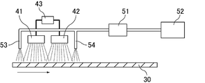
- FIG. 1 the schematic diagram which shows an example of the method of manufacturing the inorganic film
- Zn and Sn are both added to the first cathode 41 and the second cathode 42 provided in the film forming chamber of the roll-to-roll type sputtering apparatus.
- Sputtering is performed while attaching the target including the substrate film 30.
- the film forming chamber of the sputtering apparatus is depressurized by a vacuum pump, and argon gas and oxygen gas are supplied at a predetermined flow rate.
- the same target may be attached to the first cathode 41 and the second cathode 42, or different targets may be attached.
- the first cathode 41 and the second cathode 42 are connected to a bipolar power source 43, and pulse power is supplied to the first cathode 41 and the second cathode 42 by the bipolar power source 43, so that Zn Then, the target material is ejected from the target containing Sn and deposited on the surface of the base film 30 to form a thin film.
- the ratio of the number of pulses supplied from the bipolar power supply 43 to the first cathode 41 and the second cathode 42 it is ejected from the target attached to the first cathode 41 and the second cathode 42.
- the ratio of the amount of target material can be adjusted.
- the composition of the alloy oxide deposited on the surface of the base film 30 can be adjusted by controlling the pulse number ratio.
- the raw material gas containing Si and C is supplied from the first gas supply line 53 and the second gas supply line 54 of the gas spraying apparatus before and after sputtering. Spray.
- the first gas supply line 53 and the second gas supply line 54 are connected to a liquid source supply unit 52 and a vaporizer 51 that vaporizes the liquid source.
- the source gas containing Si and C is preferably supplied by vaporizing a liquid source. Examples of such a liquid source include hexamethyldisiloxane (HMDSO) hexamethyldisilazane (HMDS), tetraethoxy. Silane (TEOS) etc. are mentioned.
- the inorganic film of the present invention is excellent in gas barrier properties and hardly reduces the light transmittance even when laminated with a resin material.
- a gas barrier film in which the inorganic film of the present invention is formed on a resin film is also one aspect of the present invention.
- the refractive index of the said resin film is not specifically limited, Usually, it becomes a value below the refractive index of the film
- the material constituting the resin film is not particularly limited.
- acrylic resins such as polymethyl methacrylate, polyethyl methacrylate, polybutyl acrylate, polyethylene terephthalate, polybutylene terephthalate, isophthalate copolymer, etc.
- polyester-based resins polyester-based resins.
- polyolefin resin such as a polyethylene-type resin and a polypropylene-type resin, etc. are mentioned. Only 1 type may be used for these and 2 or more types may be used together.
- the gas barrier film of the present invention may further have a planarizing layer made of an organic substance between the resin film and the inorganic film of the present invention.
- the refractive index of the said planarization layer is not specifically limited, Usually, it becomes a value below the refractive index of the film
- the planarization layer is not particularly limited as long as it can obtain surface smoothness. For example, a composition containing an alkoxysilane having a radical polymerizable group, an alkoxysilane not having a radical polymerizable group, and water is prepared. Then, after applying the composition, those obtained by irradiating the applied composition with active energy rays may be mentioned.
- the thickness of the planarizing layer is not particularly limited, but a preferable lower limit is 0.01 ⁇ m and a preferable upper limit is 100 ⁇ m. When the thickness is less than 0.01 ⁇ m, the gas barrier property of the planarizing layer may be lowered. When the thickness exceeds 100 ⁇ m, the rigidity of the planarizing layer becomes too high, and the handleability of the gas barrier film may be lowered.
- the more preferable lower limit of the thickness is 0.1 ⁇ m, the more preferable upper limit is 50 ⁇ m, the still more preferable lower limit is 1 ⁇ m, and the still more preferable upper limit is 10 ⁇ m.
- a resin layer may be further formed on the surface of the inorganic film of the present invention opposite to the resin film.
- the gas barrier film can be flattened, stress-relaxed, adhesion improved, and the like, and the gas barrier film can be laminated to other members.
- the refractive index of the said resin layer is not specifically limited, Usually, it becomes a value below the refractive index of the film
- the resin layer is not particularly limited as long as it is made of an organic material.
- Examples of the material constituting the resin layer include ethylene-unsaturated carboxylic acid-acrylic acid ester copolymer, ethylene-unsaturated carboxylic acid-methacrylic acid ester copolymer, thermoplastic elastomer, low density polyethylene, ethylene -Vinyl acetate copolymer, polyvinylidene chloride, ionomer, vinyl chloride-vinyl acetate copolymer, ethylene-vinyl alcohol copolymer, nitrocellulose, cellulose acetate, silicone and the like.
- polyurethane-based resins such as polyether polyurethane, which is a condensate of diisocyanate and polyether polyol, and polyester polyurethane, which is a condensate of diisocyanate and polyester polyol, can be used. Only 1 type may be used for these and 2 or more types may be used together.
- the gas barrier film of the present invention has excellent gas barrier properties, and its water vapor transmission rate is not particularly limited, but is preferably less than 1.0 ⁇ 10 ⁇ 2 g / m 2 / day, and is preferably 1.0 ⁇ 10 ⁇ 3 g. Less than / m 2 / day is more preferable.
- the water vapor permeability of the gas barrier film can be measured based on the JIS K7126A method (differential pressure method). Specifically, the water vapor permeability of the gas barrier film can be measured at 40 ° C. and 90% using a differential pressure type moisture permeability measuring device (for example, GTR-300XASC, manufactured by GTR Tech).
- the gas barrier film of the present invention is excellent in transparency, and its total light transmittance is not particularly limited, but is preferably 85% or more, more preferably 90% or more.
- the total light transmittance of the gas barrier film can be measured based on JIS K7361. Specifically, the total light transmittance of the gas barrier film can be measured with a haze meter (for example, Hazeguard 2 manufactured by Toyo Seiki Seisakusho Co., Ltd.).
- the use of the inorganic film of the present invention and the gas barrier film of the present invention is not particularly limited, but it is preferably used for a flexible device that is lightweight and can be bent freely.
- a flexible device is not particularly limited, and examples thereof include display devices such as flexible solar cells and flexible displays, sensors, and the like.
- stacked with a resin material can be provided.
- membrane can be provided.
- FIG. 1 is a schematic view showing an example of a method for producing an inorganic film of the present invention.
- Example 1 Formation of flattening layer A composition containing 80 parts by weight of 3-methacryloxypropyltrimethoxysilane, 53 parts by weight of tetraethoxysilane, 30 parts by weight of titanium tetrabutoxide and 4.9 parts by weight of water was prepared. To this composition, 0.1 part by weight of 2-methyl-1 [4- (methylthio) phenyl] -2-morpholinopropan-1-one (manufactured by Ciba Specialty Chemicals, Irgacure 907) was added to add 9 W The prepolymerization was performed by irradiating with ultraviolet rays for 15 minutes using an ultraviolet lamp.
- 2-methyl-1 [4- (methylthio) phenyl] -2-morpholinopropan-1-one manufactured by Ciba Specialty Chemicals, Irgacure 907
- This composition was applied onto one surface of a PET film (Lumirror 50T60, manufactured by Toray Industries, Inc.) using a gravure coater.
- a gravure coater By irradiating the applied composition with an electron beam under the conditions of an acceleration voltage of 175 kV and an irradiation dose of 150 kGy using an electron beam irradiation apparatus (EC300 / 165/800 manufactured by ESI), 3-methacryloxypropyltrimethoxysilane
- the radical polymerization was performed to form a radical polymer.
- the main chain of the above radical polymer is obtained by allowing a PET film having a composition subjected to electron beam irradiation on one side to stand in an environment of 45 ° C.
- first cathode and second cathode first cathodes
- second cathode second cathode
- the sputtering apparatus was evacuated with a vacuum pump, and the pressure was reduced to 3.0 ⁇ 10 ⁇ 4 Pa.
- HMDSO hexamethyldisiloxane
- Sputtering was performed under the following conditions while passing a PET film having a flattening layer formed on one side.
- Example 2 A gas barrier film was obtained in the same manner as in Example 1 except that a SiCZnSnO thin film having a thickness of 250 nm was formed by balanced magnetron (BM) sputtering in “(2) Formation of inorganic film”.
- BM balanced magnetron
- Example 1 By adding only argon gas and oxygen gas as process gases without spraying hexamethyldisiloxane (HMDSO) by balanced magnetron (BM) sputtering in “(2) Formation of inorganic film”, the film thickness is 200 nm.
- a gas barrier film was obtained in the same manner as in Example 1 except that a ZnSnO thin film was formed.
- the argon gas flow rate was 50 sccm and the oxygen gas flow rate was 100 sccm.
- Example 2 By adding only argon gas and oxygen gas as process gases without spraying hexamethyldisiloxane (HMDSO) by unbalanced magnetron (UBM) sputtering in “(2) Formation of inorganic film”, the film thickness is 200 nm.
- a gas barrier film was obtained in the same manner as in Example 1 except that the ZnSnO thin film was formed.
- the argon gas flow rate was 50 sccm and the oxygen gas flow rate was 100 sccm.
- the water vapor permeability of the gas barrier film was measured at 40 ° C. and 90% with a gas barrier differential pressure type moisture permeability measuring device (GTR-300XASC, manufactured by GTR Tech). ⁇ a case the water vapor transmission rate is less than 1.0 ⁇ 10 -3 (g / m 2 / day), 1.0 ⁇ 10 -3 (g / m 2 / day) or 1.0 ⁇ 10 -2 (g / M 2 / day) was judged as ⁇ , and 1.0 ⁇ 10 ⁇ 2 (g / m 2 / day) or more was judged as ⁇ .
- GTR-300XASC gas barrier differential pressure type moisture permeability measuring device
- the total light transmittance of the gas barrier film was measured based on JIS K7361 with a transparency haze meter (manufactured by Toyo Seiki Seisakusho, Hazeguard 2). A case where the total light transmittance was 85% or more was judged as ⁇ , and a case where it was less than 85% was judged as ⁇ .
- stacked with a resin material can be provided.
- membrane can be provided.
Landscapes
- Chemical & Material Sciences (AREA)
- Chemical Kinetics & Catalysis (AREA)
- Engineering & Computer Science (AREA)
- Materials Engineering (AREA)
- Mechanical Engineering (AREA)
- Metallurgy (AREA)
- Organic Chemistry (AREA)
- Laminated Bodies (AREA)
- Physical Vapour Deposition (AREA)
Abstract
本発明は、ガスバリア性に優れ、樹脂材料と積層された際にも光線透過率を低下させにくい無機膜を提供することを目的とする。また、本発明は、該無機膜を有するガスバリアフィルムを提供することを目的とする。本発明は、ケイ素(Si)、炭素(C)、亜鉛(Zn)及びスズ(Sn)を含む複酸化物を含有し、膜中央部から膜表面に向けて膜厚方向に炭素(C)濃度が連続的に増加する無機膜である。
Description
本発明は、ガスバリア性に優れ、樹脂材料と積層された際にも光線透過率を低下させにくい無機膜に関する。また、本発明は、該無機膜を有するガスバリアフィルムに関する。
軽量で自在に曲げることのできるフレキシブルデバイスにおいては、基材や素子自体に樹脂等の有機物が用いられている。このようなフレキシブルデバイスにおいては、封止部材としてガスバリアフィルムが用いられる。
ガスバリアフィルムには、ガスバリア性、透明性、フレキシブル性等を兼ね備えることが要求されている。ガスバリアフィルムとして、例えば、ポリエチレンテレフタレート(PET)等からなる樹脂フィルム上に無機膜が形成されたフィルムが挙げられる。
特許文献1には、ガスバリア性及びフレキシブル性を併せもったガスバリアフィルムが開示されている。特許文献1では、ガスバリア性を高めるために、亜鉛スズ酸化物が用いられている。
特許文献1には、ガスバリア性及びフレキシブル性を併せもったガスバリアフィルムが開示されている。特許文献1では、ガスバリア性を高めるために、亜鉛スズ酸化物が用いられている。
しかしながら、特許文献1に開示されている亜鉛スズ酸化物は屈折率が高く、樹脂フィルムやアンカーコート層等の樹脂材料と積層された場合、それらの材料との屈折率差から光学干渉を生じる。従って、光線透過率が低下してしまうという問題点を有している。
本発明は、ガスバリア性に優れ、樹脂材料と積層された際にも光線透過率を低下させにくい無機膜を提供することを目的とする。また、本発明は、該無機膜を有するガスバリアフィルムを提供することを目的とする。
本発明は、ケイ素(Si)、炭素(C)、亜鉛(Zn)及びスズ(Sn)を含む複酸化物を含有し、膜中央部から膜表面に向けて膜厚方向に炭素(C)濃度が連続的に増加する無機膜である。
以下、本発明を詳述する。
以下、本発明を詳述する。
本発明者は、ケイ素(Si)、炭素(C)、亜鉛(Zn)及びスズ(Sn)を含む複酸化物を含有し、膜中央部から膜表面に向けて膜厚方向に炭素(C)濃度が連続的に増加する無機膜であれば、ガスバリア性に優れ、樹脂材料と積層された際にも光線透過率を低下させにくいことを見出し、本発明を完成させるに至った。
本発明の無機膜は、ケイ素(Si)、炭素(C)、亜鉛(Zn)及びスズ(Sn)を含む複酸化物を含有する。
上記複酸化物を含有することにより、本発明の無機膜は、ガスバリア性に優れたものとなる。本明細書中、ガスバリア性とは、二酸化炭素、酸素、水蒸気等の気体の透過を充分に低減させる特性を意味する。
上記複酸化物は、ケイ素(Si)、炭素(C)、亜鉛(Zn)及びスズ(Sn)を含む酸化物であればよく、特に限定されない。
上記複酸化物を含有することにより、本発明の無機膜は、ガスバリア性に優れたものとなる。本明細書中、ガスバリア性とは、二酸化炭素、酸素、水蒸気等の気体の透過を充分に低減させる特性を意味する。
上記複酸化物は、ケイ素(Si)、炭素(C)、亜鉛(Zn)及びスズ(Sn)を含む酸化物であればよく、特に限定されない。
本発明の無機膜は、上記複酸化物に加えて、例えば、In、Ti、Mg、Zr、Ni、Ta、W、Cu若しくはこれらを2種以上含む合金の酸化物又は酸化窒化物を含んでいてもよい。
本発明の無機膜において、高いガスバリア性及び屈曲性を得るためには、ZnとSnの総和に対するSnの重量比Xsが、70>Xs>0を満たしていることが好ましく、50≧Xs>0を満たしていることがより好ましく、30>Xs≧5を満たしていることが更に好ましく、10≧Xs≧5を満たしていることが特に好ましい。
なお、無機膜における元素の種類、及び、濃度は、例えば、試料表面にカーボンを蒸着後、集束イオンビーム(FIB)により薄膜切片を作製し、透過型電子顕微鏡FE-TEM(例えば、日本電子社製、JEM-2010FEF)によるエネルギー分散型X線分析(EDS線分析)等により測定することができる。
本発明の無機膜は、膜中央部から膜表面に向けて膜厚方向に炭素(C)濃度が連続的に増加する。なお、膜表面とは、両側の膜表面を意味する。
このような組成を有することにより、本発明の無機膜は、膜表面付近では比較的屈折率が小さくなり、樹脂材料と積層された際の樹脂材料との屈折率差を小さくすることができる。このため、光学干渉による光線透過率の低下を低減することができる。一方、本発明の無機膜は、膜の中心付近では比較的屈折率が大きくなり、高いガスバリア性を発揮できる組成を有することができる。
上記C濃度は、膜中央部から膜表面に向けて膜厚方向に連続的に増加していれば特に限定されないが、膜中央部では好ましい下限が0重量%、好ましい上限が5重量%であり、より好ましい上限が1重量%である。上記C濃度は、膜表面では好ましい下限が5重量%、好ましい上限が30重量%であり、より好ましい下限が10重量%、より好ましい上限が25重量%である。
このような組成を有することにより、本発明の無機膜は、膜表面付近では比較的屈折率が小さくなり、樹脂材料と積層された際の樹脂材料との屈折率差を小さくすることができる。このため、光学干渉による光線透過率の低下を低減することができる。一方、本発明の無機膜は、膜の中心付近では比較的屈折率が大きくなり、高いガスバリア性を発揮できる組成を有することができる。
上記C濃度は、膜中央部から膜表面に向けて膜厚方向に連続的に増加していれば特に限定されないが、膜中央部では好ましい下限が0重量%、好ましい上限が5重量%であり、より好ましい上限が1重量%である。上記C濃度は、膜表面では好ましい下限が5重量%、好ましい上限が30重量%であり、より好ましい下限が10重量%、より好ましい上限が25重量%である。
本発明の無機膜は、膜中央部から膜表面に向けて膜厚方向にケイ素(Si)に対するスズ(Sn)の濃度比(Sn/Si濃度比)が連続的に低下することが好ましい。これにより、光学干渉による光線透過率の低下をより低減できるとともに、ガスバリア性がより向上する。
上記Sn/Si濃度比は、膜中央部から膜表面に向けて膜厚方向に連続的に低下していれば特に限定されないが、膜中央部では1/2以上が好ましい。上記Sn/Si濃度比は、膜表面では好ましい下限が0、好ましい上限が1/5であり、より好ましい上限が1/10である。
上記Sn/Si濃度比は、膜中央部から膜表面に向けて膜厚方向に連続的に低下していれば特に限定されないが、膜中央部では1/2以上が好ましい。上記Sn/Si濃度比は、膜表面では好ましい下限が0、好ましい上限が1/5であり、より好ましい上限が1/10である。
本発明の無機膜は、膜表面を除く膜中の炭素(C)濃度がケイ素(Si)濃度よりも低いことが好ましい。これにより、光学干渉による光線透過率の低下をより低減できるとともに、ガスバリア性がより向上する。
本発明の無機膜の膜厚は特に限定されないが、充分なガスバリア性を得る観点から、好ましい下限は30nm、好ましい上限は3000nmであり、より好ましい下限は50nm、より好ましい上限は1000nmである。
本発明の無機膜を製造する方法は特に限定されず、例えば、スパッタリング法、蒸着法、イオンプレーティング法等の物理的気相成長法(PVD)や、化学的気相成長法(CVD)等が挙げられる。これらの製造方法において、膜中央部から膜表面に向けて膜厚方向にC濃度を連続的に増加させるように成膜条件を調整すればよい。
本発明の無機膜を製造する方法として、より具体的には例えば、ロールtoロール方式のスパッタリング装置と、ガス吹き付け装置とを組み合わせた装置を用いる方法が挙げられる。
上記方法では、ロールtoロール方式のスパッタリング装置の成膜室に備えられたカソードに、Zn及びSnを含むターゲットを取り付け、基材フィルムを通過させながらスパッタリングを行う。この際、スパッタリングの前後で、ガス吹き付け装置によりSi及びCを含む原料ガスの吹き付けを行う。上記方法によれば、生産速度を損なうことなく、膜の中心付近よりも膜表面においてSi濃度及びC濃度が大きく、かつ、膜表面よりも膜の中心付近においてZn濃度及びSn濃度が大きい無機膜を得ることができる。このような組成を有する無機膜は、膜表面に近づくにつれて屈折率が連続的に小さくなる。
上記方法では、ロールtoロール方式のスパッタリング装置の成膜室に備えられたカソードに、Zn及びSnを含むターゲットを取り付け、基材フィルムを通過させながらスパッタリングを行う。この際、スパッタリングの前後で、ガス吹き付け装置によりSi及びCを含む原料ガスの吹き付けを行う。上記方法によれば、生産速度を損なうことなく、膜の中心付近よりも膜表面においてSi濃度及びC濃度が大きく、かつ、膜表面よりも膜の中心付近においてZn濃度及びSn濃度が大きい無機膜を得ることができる。このような組成を有する無機膜は、膜表面に近づくにつれて屈折率が連続的に小さくなる。
上記方法におけるスパッタリング法は特に限定されないが、マグネトロンスパッタリング法が好ましい。マグネトロンスパッタリング法は、カソードに配置した磁石により磁場を生じさせ、ターゲットの前方にプラズマを発生させた状態でスパッタリングを行う方法である。マグネトロンスパッタリング法では、ターゲット近傍のプラズマ密度を高めることができるため、スパッタリング成膜速度を高めることができる。
なかでも、アンバランスドマグネトロン(UBM)スパッタリング法がより好ましい。アンバランスドマグネトロン(UBM)スパッタリング法は、磁石の移動等により意図的に磁場のバランスを崩すことにより、基材フィルム方向にプラズマを拡散させ、基材フィルムの表面及びスパッタリング成膜面のプラズマ照射量を増やした状態でスパッタリングを行う方法である。アンバランスドマグネトロン(UBM)スパッタリング法によれば、より緻密な無機膜を得ることができ、無機膜のガスバリア性がより向上する。また、アンバランスドマグネトロン(UBM)スパッタリング法によれば、膜中央部及び膜表面でのSn/Si濃度比を上記範囲に調整しやすい。
また、上記方法におけるスパッタリング法としては、より緻密な無機膜を得ることができ、無機膜のガスバリア性がより向上することから、スパッタリングと同時に基材フィルムの表面へのイオンビーム照射を行うイオンアシストスパッタリング法、基材フィルム側にバイアスを付加するバイアススパッタリング法等も好ましい。
なかでも、アンバランスドマグネトロン(UBM)スパッタリング法がより好ましい。アンバランスドマグネトロン(UBM)スパッタリング法は、磁石の移動等により意図的に磁場のバランスを崩すことにより、基材フィルム方向にプラズマを拡散させ、基材フィルムの表面及びスパッタリング成膜面のプラズマ照射量を増やした状態でスパッタリングを行う方法である。アンバランスドマグネトロン(UBM)スパッタリング法によれば、より緻密な無機膜を得ることができ、無機膜のガスバリア性がより向上する。また、アンバランスドマグネトロン(UBM)スパッタリング法によれば、膜中央部及び膜表面でのSn/Si濃度比を上記範囲に調整しやすい。
また、上記方法におけるスパッタリング法としては、より緻密な無機膜を得ることができ、無機膜のガスバリア性がより向上することから、スパッタリングと同時に基材フィルムの表面へのイオンビーム照射を行うイオンアシストスパッタリング法、基材フィルム側にバイアスを付加するバイアススパッタリング法等も好ましい。
図1に、本発明の無機膜を製造する方法の一例を示す模式図を示す。
図1に示す本発明の無機膜を製造する方法においては、ロールtoロール方式のスパッタリング装置の成膜室に備えられた第1のカソード41及び第2のカソード42に、いずれもZn及びSnを含むターゲットを取り付け、基材フィルム30を通過させながらスパッタリングを行う。スパッタリング装置の成膜室は、真空ポンプにより減圧され、また、アルゴンガス及び酸素ガスが所定の流量で供給されている。
第1のカソード41及び第2のカソード42には、同一のターゲットが取り付けられてもよいし、異なるターゲットが取り付けられてもよい。第1のカソード41及び第2のカソード42は、バイポーラー電源43に接続されており、バイポーラー電源43により第1のカソード41及び第2のカソード42にパルス電力が供給されることで、Zn及びSnを含むターゲットからターゲット材料が弾き出され、基材フィルム30の表面に堆積して薄膜が形成される。
なお、バイポーラー電源43からの第1のカソード41及び第2のカソード42に供給するパルス数比を制御することにより、第1のカソード41及び第2のカソード42に取り付けられたターゲットから弾き出されるターゲット材料の量の比を調整することができる。第1のカソード41及び第2のカソード42に異なるターゲットを取り付けた場合、パルス数比を制御することにより、基材フィルム30の表面に堆積する合金酸化物の組成を調整することができる。
図1に示す本発明の無機膜を製造する方法においては、ロールtoロール方式のスパッタリング装置の成膜室に備えられた第1のカソード41及び第2のカソード42に、いずれもZn及びSnを含むターゲットを取り付け、基材フィルム30を通過させながらスパッタリングを行う。スパッタリング装置の成膜室は、真空ポンプにより減圧され、また、アルゴンガス及び酸素ガスが所定の流量で供給されている。
第1のカソード41及び第2のカソード42には、同一のターゲットが取り付けられてもよいし、異なるターゲットが取り付けられてもよい。第1のカソード41及び第2のカソード42は、バイポーラー電源43に接続されており、バイポーラー電源43により第1のカソード41及び第2のカソード42にパルス電力が供給されることで、Zn及びSnを含むターゲットからターゲット材料が弾き出され、基材フィルム30の表面に堆積して薄膜が形成される。
なお、バイポーラー電源43からの第1のカソード41及び第2のカソード42に供給するパルス数比を制御することにより、第1のカソード41及び第2のカソード42に取り付けられたターゲットから弾き出されるターゲット材料の量の比を調整することができる。第1のカソード41及び第2のカソード42に異なるターゲットを取り付けた場合、パルス数比を制御することにより、基材フィルム30の表面に堆積する合金酸化物の組成を調整することができる。
図1に示す本発明の無機膜を製造する方法においては、スパッタリングの前後で、ガス吹き付け装置の第1のガス供給ライン53及び第2のガス供給ライン54から、Si及びCを含む原料ガスの吹き付けを行う。第1のガス供給ライン53及び第2のガス供給ライン54は、液体原料供給器52、及び、液体原料を気化する気化器51に接続している。
上記Si及びCを含む原料ガスは、液体原料を気化させることにより供給されることが好ましく、このような液体原料として、例えば、ヘキサメチルジシロキサン(HMDSO)ヘキサメチルジシラザン(HMDS)、テトラエトキシシラン(TEOS)等が挙げられる。
上記Si及びCを含む原料ガスは、液体原料を気化させることにより供給されることが好ましく、このような液体原料として、例えば、ヘキサメチルジシロキサン(HMDSO)ヘキサメチルジシラザン(HMDS)、テトラエトキシシラン(TEOS)等が挙げられる。
本発明の無機膜は、ガスバリア性に優れ、樹脂材料と積層された際にも光線透過率を低下させにくいものである。
樹脂フィルム上に本発明の無機膜が形成されているガスバリアフィルムもまた、本発明の1つである。
樹脂フィルム上に本発明の無機膜が形成されているガスバリアフィルムもまた、本発明の1つである。
上記樹脂フィルムの屈折率は特に限定されないが、通常、本発明の無機膜の膜表面の屈折率以下の値となる。
上記樹脂フィルムを構成している材料は特に限定されず、例えば、ポリメタクリル酸メチル、ポリメタクリル酸エチル、ポリアクリル酸ブチル等のアクリル系樹脂、ポリエチレンテレフタレート、ポリブチレンテレフタレート、イソフタレート共重合体等のポリエステル系樹脂等が挙げられる。また、ポリエチレン系樹脂、ポリプロピレン系樹脂等のポリオレフィン系樹脂等が挙げられる。これらは1種のみが用いられてもよく、2種以上が併用されてもよい。
上記樹脂フィルムを構成している材料は特に限定されず、例えば、ポリメタクリル酸メチル、ポリメタクリル酸エチル、ポリアクリル酸ブチル等のアクリル系樹脂、ポリエチレンテレフタレート、ポリブチレンテレフタレート、イソフタレート共重合体等のポリエステル系樹脂等が挙げられる。また、ポリエチレン系樹脂、ポリプロピレン系樹脂等のポリオレフィン系樹脂等が挙げられる。これらは1種のみが用いられてもよく、2種以上が併用されてもよい。
本発明のガスバリアフィルムは、上記樹脂フィルムと本発明の無機膜との間に、更に、有機物からなる平坦化層を有していてもよい。
上記平坦化層の屈折率は特に限定されないが、通常、本発明の無機膜の膜表面の屈折率以下の値となる。
上記平坦化層は、表面の平滑性を得られるものであれば特に限定されず、例えば、ラジカル重合性基を有するアルコキシシラン、ラジカル重合性基を有しないアルコキシシラン及び水を含む組成物を作製し、該組成物を塗布した後、塗布した上記組成物に活性エネルギー線を照射することにより得られるものが挙げられる。
上記平坦化層の屈折率は特に限定されないが、通常、本発明の無機膜の膜表面の屈折率以下の値となる。
上記平坦化層は、表面の平滑性を得られるものであれば特に限定されず、例えば、ラジカル重合性基を有するアルコキシシラン、ラジカル重合性基を有しないアルコキシシラン及び水を含む組成物を作製し、該組成物を塗布した後、塗布した上記組成物に活性エネルギー線を照射することにより得られるものが挙げられる。
上記平坦化層の厚みは特に限定されないが、好ましい下限は0.01μm、好ましい上限は100μmである。上記厚みが0.01μm未満であると、上記平坦化層のガスバリア性が低下することがある。上記厚みが100μmを超えると、上記平坦化層の剛性が高くなり過ぎて、ガスバリアフィルムの取扱性が低下することがある。上記厚みのより好ましい下限は0.1μm、より好ましい上限は50μmであり、更に好ましい下限は1μm、更に好ましい上限は10μmである。
本発明のガスバリアフィルムは、更に、本発明の無機膜の上記樹脂フィルムとは反対の面に樹脂層が形成されていてもよい。
上記樹脂層が形成されていることにより、ガスバリアフィルムの平坦化、応力緩和、密着性向上等を行うことができ、また、ガスバリアフィルムを他の部材に対してラミネートすることが可能となる。
上記樹脂層が形成されていることにより、ガスバリアフィルムの平坦化、応力緩和、密着性向上等を行うことができ、また、ガスバリアフィルムを他の部材に対してラミネートすることが可能となる。
上記樹脂層の屈折率は特に限定されないが、通常、本発明の無機膜の膜表面の屈折率以下の値となる。
上記樹脂層は特に限定されず、有機物により構成されていればよい。上記樹脂層を構成している材料として、例えば、エチレン-不飽和カルボン酸-アクリル酸エステル共重合体、エチレン-不飽和カルボン酸-メタクリル酸エステル共重合体、熱可塑性エラストマー、低密度ポリエチレン、エチレン-酢酸ビニル共重合体、ポリ塩化ビニリデン、アイオノマー、塩化ビニル-酢酸ビニル共重合体、エチレン-ビニルアルコール共重合体、ニトロセルロース、酢酸セルロース、シリコーン等が挙げられる。また、ジイソシアネートとポリエーテルポリオールの縮合体であるポリエーテルポリウレタン、ジイソシアネートとポリエステルポリオールの縮合体であるポリエステルポリウレタン等のポリウレタン系樹脂等が挙げられる。これらは1種のみが用いられてもよく、2種以上が併用されてもよい。
上記樹脂層は特に限定されず、有機物により構成されていればよい。上記樹脂層を構成している材料として、例えば、エチレン-不飽和カルボン酸-アクリル酸エステル共重合体、エチレン-不飽和カルボン酸-メタクリル酸エステル共重合体、熱可塑性エラストマー、低密度ポリエチレン、エチレン-酢酸ビニル共重合体、ポリ塩化ビニリデン、アイオノマー、塩化ビニル-酢酸ビニル共重合体、エチレン-ビニルアルコール共重合体、ニトロセルロース、酢酸セルロース、シリコーン等が挙げられる。また、ジイソシアネートとポリエーテルポリオールの縮合体であるポリエーテルポリウレタン、ジイソシアネートとポリエステルポリオールの縮合体であるポリエステルポリウレタン等のポリウレタン系樹脂等が挙げられる。これらは1種のみが用いられてもよく、2種以上が併用されてもよい。
本発明のガスバリアフィルムは、ガスバリア性に優れるものであり、その水蒸気透過率は特に限定されないが、1.0×10⁻²g/m2/day未満が好ましく、1.0×10-3g/m2/day未満がより好ましい。
なお、ガスバリアフィルムの水蒸気透過率は、JIS K7126A法(差圧法)に基づいて測定することができる。具体的には、差圧式透湿度測定装置(例えば、GTRテック社製、GTR-300XASC)により40℃,90%の条件でガスバリアフィルムの水蒸気透過率を測定することができる。
なお、ガスバリアフィルムの水蒸気透過率は、JIS K7126A法(差圧法)に基づいて測定することができる。具体的には、差圧式透湿度測定装置(例えば、GTRテック社製、GTR-300XASC)により40℃,90%の条件でガスバリアフィルムの水蒸気透過率を測定することができる。
本発明のガスバリアフィルムは、透明性にも優れるものであり、その全光線透過率は特に限定されないが、85%以上が好ましく、90%以上がより好ましい。
なお、ガスバリアフィルムの全光線透過率は、JIS K7361に基づいて測定することができる。具体的には、ヘイズメーター(例えば、東洋精機製作所社製、ヘイズガード2)によりガスバリアフィルムの全光線透過率を測定することができる。
なお、ガスバリアフィルムの全光線透過率は、JIS K7361に基づいて測定することができる。具体的には、ヘイズメーター(例えば、東洋精機製作所社製、ヘイズガード2)によりガスバリアフィルムの全光線透過率を測定することができる。
本発明の無機膜及び本発明のガスバリアフィルムの用途は特に限定されないが、軽量で自在に曲げることのできるフレキシブルデバイスに用いられることが好ましい。このようなフレキシブルデバイスは特に限定されず、例えば、フレキシブル太陽電池、フレキシブルディスプレイ等の表示装置、センサー等が挙げられる。
本発明によれば、ガスバリア性に優れ、樹脂材料と積層された際にも光線透過率を低下させにくい無機膜を提供することができる。また、本発明によれば、該無機膜を有するガスバリアフィルムを提供することができる。
以下に実施例を挙げて本発明を更に詳しく説明するが、本発明はこれら実施例のみに限定されない。
(実施例1)
(1)平坦化層の形成
3-メタクリロキシプロピルトリメトキシシラン80重量部、テトラエトキシシラン53重量部、チタニウムテトラブトキシド30重量部及び水4.9重量部含む組成物を作製した。この組成物に2-メチル-1[4-(メチルチオ)フェニル]-2-モリフォリノプロパン-1-オン(チバ・スペシャリティーケミカルズ社製、イルガキュア907)0.1重量部を加えて、9Wの紫外線ランプを用いて紫外線を15分間照射して予備重合を行った。
この組成物を、グラビアコーターによりPETフィルム(東レ社製、ルミラー50T60)の一面に塗布した。塗布した組成物に電子線照射装置(ESI社製、EC300/165/800)を用いて、加速電圧175kV、照射線量150kGyの条件で電子線を照射することによって、3-メタクリロキシプロピルトリメトキシシランのラジカル重合を行ってラジカル重合体を形成した。
電子線照射を行った組成物を一面に有するPETフィルムを45℃、相対湿度65%RHの環境下に1時間放置し、加水分解及び脱水縮合反応を促進することにより上記ラジカル重合体の主鎖間を架橋するテトラエトキシシランの脱水縮合物を形成し、平坦化層(厚み8μm)を得た。
(1)平坦化層の形成
3-メタクリロキシプロピルトリメトキシシラン80重量部、テトラエトキシシラン53重量部、チタニウムテトラブトキシド30重量部及び水4.9重量部含む組成物を作製した。この組成物に2-メチル-1[4-(メチルチオ)フェニル]-2-モリフォリノプロパン-1-オン(チバ・スペシャリティーケミカルズ社製、イルガキュア907)0.1重量部を加えて、9Wの紫外線ランプを用いて紫外線を15分間照射して予備重合を行った。
この組成物を、グラビアコーターによりPETフィルム(東レ社製、ルミラー50T60)の一面に塗布した。塗布した組成物に電子線照射装置(ESI社製、EC300/165/800)を用いて、加速電圧175kV、照射線量150kGyの条件で電子線を照射することによって、3-メタクリロキシプロピルトリメトキシシランのラジカル重合を行ってラジカル重合体を形成した。
電子線照射を行った組成物を一面に有するPETフィルムを45℃、相対湿度65%RHの環境下に1時間放置し、加水分解及び脱水縮合反応を促進することにより上記ラジカル重合体の主鎖間を架橋するテトラエトキシシランの脱水縮合物を形成し、平坦化層(厚み8μm)を得た。
(2)無機膜の形成
ロールtoロール方式のスパッタリング装置の成膜室に備えられた2つのカソード(第1のカソード、第2のカソード)に、いずれもZnSn合金(Zn:Sn=50:50重量%)ターゲットを取り付けた。スパッタリング装置を真空ポンプにより排気し、3.0×10⁻⁴Paまで減圧した。
一方、ガス吹き付け装置の液体原料供給器に、液体原料としてヘキサメチルジシロキサン(HMDSO)を投入した。
平坦化層が片面に形成されたPETフィルムを通過させながら、以下に示す条件でスパッタリングを行った。この際、スパッタリングの前後で、ガス吹き付け装置の2つのガス供給ライン(第1のガス供給ライン、第2のガス供給ライン)から、気化器により気化されたヘキサメチルジシロキサン(HMDSO)の吹き付けを行い、平坦化層上に膜厚250nmのSiCZnSnO薄膜を形成した。
(成膜条件A)
方式:アンバランスドマグネトロン(UBM)スパッタリング
基材搬送速度:0.1m/分,張力:100N,キャンロール冷却温度:10℃
アルゴンガス流量:50sccm,酸素ガス流量:100sccm,HMDSOガス流量:40sccm
電源出力:5kW
ロールtoロール方式のスパッタリング装置の成膜室に備えられた2つのカソード(第1のカソード、第2のカソード)に、いずれもZnSn合金(Zn:Sn=50:50重量%)ターゲットを取り付けた。スパッタリング装置を真空ポンプにより排気し、3.0×10⁻⁴Paまで減圧した。
一方、ガス吹き付け装置の液体原料供給器に、液体原料としてヘキサメチルジシロキサン(HMDSO)を投入した。
平坦化層が片面に形成されたPETフィルムを通過させながら、以下に示す条件でスパッタリングを行った。この際、スパッタリングの前後で、ガス吹き付け装置の2つのガス供給ライン(第1のガス供給ライン、第2のガス供給ライン)から、気化器により気化されたヘキサメチルジシロキサン(HMDSO)の吹き付けを行い、平坦化層上に膜厚250nmのSiCZnSnO薄膜を形成した。
(成膜条件A)
方式:アンバランスドマグネトロン(UBM)スパッタリング
基材搬送速度:0.1m/分,張力:100N,キャンロール冷却温度:10℃
アルゴンガス流量:50sccm,酸素ガス流量:100sccm,HMDSOガス流量:40sccm
電源出力:5kW
(3)無機膜の組成分析
得られた無機膜について、集束イオンビーム(FIB)により薄膜切片を作製し、透過型電子顕微鏡FE-TEM(日本電子社製、JEM-2010FEF)によるエネルギー分散型X線分析(EDS線分析)を行うことにより、組成分析を行った。
得られた無機膜について、集束イオンビーム(FIB)により薄膜切片を作製し、透過型電子顕微鏡FE-TEM(日本電子社製、JEM-2010FEF)によるエネルギー分散型X線分析(EDS線分析)を行うことにより、組成分析を行った。
(実施例2)
「上記(2)無機膜の形成」においてバランスドマグネトロン(BM)スパッタリングにより、膜厚250nmのSiCZnSnO薄膜を形成したこと以外は実施例1と同様にしてガスバリアフィルムを得た。
「上記(2)無機膜の形成」においてバランスドマグネトロン(BM)スパッタリングにより、膜厚250nmのSiCZnSnO薄膜を形成したこと以外は実施例1と同様にしてガスバリアフィルムを得た。
(比較例1)
「上記(2)無機膜の形成」においてバランスドマグネトロン(BM)スパッタリングにより、ヘキサメチルジシロキサン(HMDSO)の吹き付けを行わずプロセスガスとしてアルゴンガス及び酸素ガスのみ添加することで、膜厚200nmのZnSnO薄膜を形成したこと以外は実施例1と同様にしてガスバリアフィルムを得た。なお、アルゴンガス流量50sccm、酸素ガス流量100sccmとした。
「上記(2)無機膜の形成」においてバランスドマグネトロン(BM)スパッタリングにより、ヘキサメチルジシロキサン(HMDSO)の吹き付けを行わずプロセスガスとしてアルゴンガス及び酸素ガスのみ添加することで、膜厚200nmのZnSnO薄膜を形成したこと以外は実施例1と同様にしてガスバリアフィルムを得た。なお、アルゴンガス流量50sccm、酸素ガス流量100sccmとした。
(比較例2)
「上記(2)無機膜の形成」においてアンバランスドマグネトロン(UBM)スパッタリングにより、ヘキサメチルジシロキサン(HMDSO)の吹き付けを行わずプロセスガスとしてアルゴンガス及び酸素ガスのみ添加することで、膜厚200nmのZnSnO薄膜を形成したこと以外は実施例1と同様にしてガスバリアフィルムを得た。なお、アルゴンガス流量50sccm、酸素ガス流量100sccmとした。
「上記(2)無機膜の形成」においてアンバランスドマグネトロン(UBM)スパッタリングにより、ヘキサメチルジシロキサン(HMDSO)の吹き付けを行わずプロセスガスとしてアルゴンガス及び酸素ガスのみ添加することで、膜厚200nmのZnSnO薄膜を形成したこと以外は実施例1と同様にしてガスバリアフィルムを得た。なお、アルゴンガス流量50sccm、酸素ガス流量100sccmとした。
<評価>
実施例、比較例で得られたガスバリアフィルムについて、以下の評価を行った。結果を表1に示した。
実施例、比較例で得られたガスバリアフィルムについて、以下の評価を行った。結果を表1に示した。
(1)ガスバリア性
差圧式透湿度測定装置(GTRテック社製、GTR-300XASC)により40℃,90%の条件でガスバリアフィルムの水蒸気透過率を測定した。
水蒸気透過率が1.0×10⁻³(g/m2/day)未満の場合を○、1.0×10-3(g/m2/day)以上1.0×10-2(g/m2/day)未満の場合を△、1.0×10-2(g/m2/day)以上の場合を×と判定した。
差圧式透湿度測定装置(GTRテック社製、GTR-300XASC)により40℃,90%の条件でガスバリアフィルムの水蒸気透過率を測定した。
水蒸気透過率が1.0×10⁻³(g/m2/day)未満の場合を○、1.0×10-3(g/m2/day)以上1.0×10-2(g/m2/day)未満の場合を△、1.0×10-2(g/m2/day)以上の場合を×と判定した。
(2)透明性
ヘイズメーター(東洋精機製作所社製、ヘイズガード2)によりJIS K7361に基づいてガスバリアフィルムの全光線透過率を測定した。
全光線透過率が85%以上の場合を○、85%未満の場合を×と判定した。
ヘイズメーター(東洋精機製作所社製、ヘイズガード2)によりJIS K7361に基づいてガスバリアフィルムの全光線透過率を測定した。
全光線透過率が85%以上の場合を○、85%未満の場合を×と判定した。

本発明によれば、ガスバリア性に優れ、樹脂材料と積層された際にも光線透過率を低下させにくい無機膜を提供することができる。また、本発明によれば、該無機膜を有するガスバリアフィルムを提供することができる。
30 基材フィルム
41 第1のカソード
42 第2のカソード
43 バイポーラー電源
51 気化器
52 液体原料供給器
53 第1のガス供給ライン
54 第2のガス供給ライン
41 第1のカソード
42 第2のカソード
43 バイポーラー電源
51 気化器
52 液体原料供給器
53 第1のガス供給ライン
54 第2のガス供給ライン
Claims (5)
- ケイ素(Si)、炭素(C)、亜鉛(Zn)及びスズ(Sn)を含む複酸化物を含有し、
膜中央部から膜表面に向けて膜厚方向に炭素(C)濃度が連続的に増加する
ことを特徴とする無機膜。 - 膜中央部から膜表面に向けて膜厚方向にケイ素(Si)に対するスズ(Sn)の濃度比(Sn/Si濃度比)が連続的に低下することを特徴とする請求項1記載の無機膜。
- 樹脂フィルム上に請求項1又は2記載の無機膜が形成されていることを特徴とするガスバリアフィルム。
- 樹脂フィルムと無機膜との間に、更に、有機物からなる平坦化層を有することを特徴とする請求項3記載のガスバリアフィルム。
- 更に、無機膜の樹脂フィルムとは反対の面に樹脂層が形成されていることを特徴とする請求項3又は4記載のガスバリアフィルム。
Priority Applications (1)
| Application Number | Priority Date | Filing Date | Title |
|---|---|---|---|
| JP2018530185A JP6606614B2 (ja) | 2017-03-31 | 2018-03-23 | 無機膜及びガスバリアフィルム |
Applications Claiming Priority (2)
| Application Number | Priority Date | Filing Date | Title |
|---|---|---|---|
| JP2017-072769 | 2017-03-31 | ||
| JP2017072769 | 2017-03-31 |
Publications (1)
| Publication Number | Publication Date |
|---|---|
| WO2018180975A1 true WO2018180975A1 (ja) | 2018-10-04 |
Family
ID=63677129
Family Applications (1)
| Application Number | Title | Priority Date | Filing Date |
|---|---|---|---|
| PCT/JP2018/011677 Ceased WO2018180975A1 (ja) | 2017-03-31 | 2018-03-23 | 無機膜及びガスバリアフィルム |
Country Status (3)
| Country | Link |
|---|---|
| JP (1) | JP6606614B2 (ja) |
| TW (1) | TW201841736A (ja) |
| WO (1) | WO2018180975A1 (ja) |
Cited By (2)
| Publication number | Priority date | Publication date | Assignee | Title |
|---|---|---|---|---|
| JP2020114667A (ja) * | 2019-01-17 | 2020-07-30 | 凸版印刷株式会社 | ガスバリア性積層体およびその製造方法 |
| WO2022190929A1 (ja) * | 2021-03-10 | 2022-09-15 | 日東電工株式会社 | 透明バリアフィルム |
Citations (4)
| Publication number | Priority date | Publication date | Assignee | Title |
|---|---|---|---|---|
| JP2005293821A (ja) * | 2004-03-10 | 2005-10-20 | Matsushita Electric Ind Co Ltd | 情報記録媒体とその製造方法 |
| WO2015002089A1 (ja) * | 2013-07-01 | 2015-01-08 | 積水化学工業株式会社 | 無機膜及び積層体 |
| JP2015223784A (ja) * | 2014-05-29 | 2015-12-14 | 積水化学工業株式会社 | バリアフィルム、積層バリアフィルム及びそれらの製造方法 |
| JP2016124219A (ja) * | 2015-01-05 | 2016-07-11 | 積水化学工業株式会社 | 積層無機膜及びバリアフィルム |
Family Cites Families (2)
| Publication number | Priority date | Publication date | Assignee | Title |
|---|---|---|---|---|
| JP5691947B2 (ja) * | 2011-09-02 | 2015-04-01 | コニカミノルタ株式会社 | ガスバリア性フィルム及びガスバリア性フィルムの製造方法 |
| JP6003799B2 (ja) * | 2013-05-15 | 2016-10-05 | コニカミノルタ株式会社 | ガスバリア性フィルムの製造方法 |
-
2018
- 2018-03-23 JP JP2018530185A patent/JP6606614B2/ja active Active
- 2018-03-23 WO PCT/JP2018/011677 patent/WO2018180975A1/ja not_active Ceased
- 2018-03-26 TW TW107110196A patent/TW201841736A/zh unknown
Patent Citations (4)
| Publication number | Priority date | Publication date | Assignee | Title |
|---|---|---|---|---|
| JP2005293821A (ja) * | 2004-03-10 | 2005-10-20 | Matsushita Electric Ind Co Ltd | 情報記録媒体とその製造方法 |
| WO2015002089A1 (ja) * | 2013-07-01 | 2015-01-08 | 積水化学工業株式会社 | 無機膜及び積層体 |
| JP2015223784A (ja) * | 2014-05-29 | 2015-12-14 | 積水化学工業株式会社 | バリアフィルム、積層バリアフィルム及びそれらの製造方法 |
| JP2016124219A (ja) * | 2015-01-05 | 2016-07-11 | 積水化学工業株式会社 | 積層無機膜及びバリアフィルム |
Cited By (4)
| Publication number | Priority date | Publication date | Assignee | Title |
|---|---|---|---|---|
| JP2020114667A (ja) * | 2019-01-17 | 2020-07-30 | 凸版印刷株式会社 | ガスバリア性積層体およびその製造方法 |
| JP7618960B2 (ja) | 2019-01-17 | 2025-01-22 | Toppanホールディングス株式会社 | ガスバリア性積層体およびその製造方法 |
| WO2022190929A1 (ja) * | 2021-03-10 | 2022-09-15 | 日東電工株式会社 | 透明バリアフィルム |
| JP2022138696A (ja) * | 2021-03-10 | 2022-09-26 | 日東電工株式会社 | 透明バリアフィルム |
Also Published As
| Publication number | Publication date |
|---|---|
| JP6606614B2 (ja) | 2019-11-13 |
| JPWO2018180975A1 (ja) | 2019-04-04 |
| TW201841736A (zh) | 2018-12-01 |
Similar Documents
| Publication | Publication Date | Title |
|---|---|---|
| CN1756856B (zh) | 电介质阻挡层膜 | |
| JP5667732B1 (ja) | 無機膜及び積層体 | |
| KR102255614B1 (ko) | 가스 배리어성 필름 | |
| CN111511814B (zh) | 有机无机杂化膜 | |
| Spee et al. | Using hot wire and initiated chemical vapor deposition for gas barrier thin film encapsulation | |
| JP5538361B2 (ja) | 透明バリア層システム | |
| JPWO2005100014A1 (ja) | 透明ガスバリア性積層フィルム | |
| JP6606614B2 (ja) | 無機膜及びガスバリアフィルム | |
| TWI691412B (zh) | 氣阻性層積體及其製造方法、電子裝置用元件以及電子裝置 | |
| JP6310316B2 (ja) | バリアフィルム | |
| JP5930341B2 (ja) | 透明なバリア層系を析出する方法 | |
| JP6709171B2 (ja) | 透明導電膜及び透明導電膜の製造方法 | |
| JP6413539B2 (ja) | ガスバリア性積層フィルム及び該ガスバリア性積層フィルムの製造方法 | |
| JP5930340B2 (ja) | 透明なバリア層系を析出する方法 | |
| JP2003251732A (ja) | 透明ガスバリア薄膜被覆フィルム | |
| JP5452209B2 (ja) | 透明体およびその製造方法 | |
| JP2016124219A (ja) | 積層無機膜及びバリアフィルム | |
| CN101756626A (zh) | 一种窗帘 | |
| KR102732322B1 (ko) | 가스 배리어성 금속산화물 증착 필름 | |
| JP7823351B2 (ja) | 積層体 | |
| JP2012057237A (ja) | ガスバリアフィルムの製造方法 | |
| JP2017119362A (ja) | ガスバリアフィルムおよびその製造方法 | |
| Taga et al. | Sputter joining of TiO2/SiO2 thin film system | |
| Lee et al. | Characteristics of Silicon Oxynitride Barrier Films Grown on Poly (ethylene naphthalate) by Ion-Beam-Assisted Deposition | |
| JP2014188884A (ja) | ガスバリア積層フィルム |
Legal Events
| Date | Code | Title | Description |
|---|---|---|---|
| ENP | Entry into the national phase |
Ref document number: 2018530185 Country of ref document: JP Kind code of ref document: A |
|
| 121 | Ep: the epo has been informed by wipo that ep was designated in this application |
Ref document number: 18776115 Country of ref document: EP Kind code of ref document: A1 |
|
| NENP | Non-entry into the national phase |
Ref country code: DE |
|
| 122 | Ep: pct application non-entry in european phase |
Ref document number: 18776115 Country of ref document: EP Kind code of ref document: A1 |