WO2018180558A1 - Internal combustion engine - Google Patents
Internal combustion engine Download PDFInfo
- Publication number
- WO2018180558A1 WO2018180558A1 PCT/JP2018/010294 JP2018010294W WO2018180558A1 WO 2018180558 A1 WO2018180558 A1 WO 2018180558A1 JP 2018010294 W JP2018010294 W JP 2018010294W WO 2018180558 A1 WO2018180558 A1 WO 2018180558A1
- Authority
- WO
- WIPO (PCT)
- Prior art keywords
- decompression
- camshaft
- follower
- concave
- internal combustion
- Prior art date
Links
Images


Classifications
-
- F—MECHANICAL ENGINEERING; LIGHTING; HEATING; WEAPONS; BLASTING
- F01—MACHINES OR ENGINES IN GENERAL; ENGINE PLANTS IN GENERAL; STEAM ENGINES
- F01L—CYCLICALLY OPERATING VALVES FOR MACHINES OR ENGINES
- F01L13/00—Modifications of valve-gear to facilitate reversing, braking, starting, changing compression ratio, or other specific operations
- F01L13/08—Modifications of valve-gear to facilitate reversing, braking, starting, changing compression ratio, or other specific operations for decompression, e.g. during starting; for changing compression ratio
-
- F—MECHANICAL ENGINEERING; LIGHTING; HEATING; WEAPONS; BLASTING
- F01—MACHINES OR ENGINES IN GENERAL; ENGINE PLANTS IN GENERAL; STEAM ENGINES
- F01L—CYCLICALLY OPERATING VALVES FOR MACHINES OR ENGINES
- F01L1/00—Valve-gear or valve arrangements, e.g. lift-valve gear
- F01L1/02—Valve drive
- F01L1/04—Valve drive by means of cams, camshafts, cam discs, eccentrics or the like
- F01L1/08—Shape of cams
-
- F—MECHANICAL ENGINEERING; LIGHTING; HEATING; WEAPONS; BLASTING
- F01—MACHINES OR ENGINES IN GENERAL; ENGINE PLANTS IN GENERAL; STEAM ENGINES
- F01L—CYCLICALLY OPERATING VALVES FOR MACHINES OR ENGINES
- F01L13/00—Modifications of valve-gear to facilitate reversing, braking, starting, changing compression ratio, or other specific operations
- F01L13/08—Modifications of valve-gear to facilitate reversing, braking, starting, changing compression ratio, or other specific operations for decompression, e.g. during starting; for changing compression ratio
- F01L13/085—Modifications of valve-gear to facilitate reversing, braking, starting, changing compression ratio, or other specific operations for decompression, e.g. during starting; for changing compression ratio the valve-gear having an auxiliary cam protruding from the main cam profile
Definitions
- the present invention relates to a decompression device for an internal combustion engine.
- Patent Document 1 discloses a decompression device for an internal combustion engine.
- the decompression device includes a decompression cam having a small-diameter partial cylindrical surface having an axis parallel to the rotation axis of the camshaft.
- the decompression cam causes a part of the partial cylindrical surface to protrude from the virtual cylindrical surface coaxial with the camshaft at a rotation speed less than a preset value.
- the slipper of the exhaust side rocker arm contacts the protruding decompression cam and opens the exhaust valve. By opening the exhaust valve during the compression stroke in the low rotation range, the driving resistance of the piston is reduced and the vibration of the internal combustion engine is suppressed.
- the present invention has been made in view of the above circumstances, and an object thereof is to provide an internal combustion engine that can further reduce the collision noise between the decompression cam and the exhaust-side rocker arm and the seating noise of the exhaust valve.
- a base surface having a shape of a partial cylindrical surface coaxial with the rotation axis of the camshaft, and the base surface is provided on the camshaft continuously to the base surface in the rotation direction.
- a lift surface that swells outward in the radial direction and defines the lift amount of the exhaust valve, and an exhaust-side rocker arm that maintains contact with the base surface and the lift surface to maintain the exhaust-side rocker arm.
- a cam follower that causes rocking, a decompression cam that projects a curved projecting surface having a generatrix parallel to the rotational axis of the camshaft from a virtual cylindrical surface that is coaxial with the camshaft and is less than a preset number of revolutions, and Provided on the exhaust-side rocker arm outside the virtual cylindrical surface, facing the virtual cylindrical surface at a position closest to the virtual cylindrical surface and contacting the curved projecting surface A curved convex convex follower surface and a concave curved surface provided in the forward rotation direction of the camshaft and upstream of the convex decompression follower surface and having a generatrix parallel to the rotational axis of the camshaft.
- An internal combustion engine is provided that includes a concave decompressor follower surface that contacts the projecting surface.
- the upstream end of the concave decompression follower surface is provided at a position farther from the rotational axis of the camshaft than the curved projecting surface.
- the concave decompression follower surface moves away from the rotation axis of the camshaft as the distance from the convex decompression follower surface increases.
- the internal combustion engine is formed between the convex decompression follower surface and the concave decompression follower surface, and more than the curved projecting surface.
- An auxiliary concave decompressor follower surface composed of a concave curved surface having a small curvature is further provided.
- the auxiliary concave decompression follower surface is formed by a part of a cylindrical surface having a larger curvature than the concave decompression follower surface.
- the internal combustion engine is provided downstream of the convex decompression follower surface in the forward rotation direction of the camshaft, It further includes a second concave decompression follower surface that is formed on a concave curved surface having a generatrix parallel to the rotation axis and contacts the curved convex surface.
- the base surface having a shape of a partial cylindrical surface coaxial with the rotation axis of the camshaft, and the camshaft is provided on the camshaft continuously to the base surface in the rotation direction, and has a diameter larger than that of the base surface.
- a lift surface that swells outward in the direction and defines the lift amount of the exhaust valve, and an exhaust-side rocker arm that maintains contact with the base surface and the lift surface to swing the exhaust-side rocker arm.
- a follower surface is provided downstream of the convex decompression follower surface in the forward rotation direction of the camshaft, and is formed as a concave curved surface having a generatrix parallel to the rotation axis of the camshaft and contacts the curved projecting surface
- An internal combustion engine having a concave decompressor follower surface is provided.
- the downstream end of the concave decompression follower surface is provided at a position farther from the rotational axis of the camshaft than the curved projecting surface.
- the concave decompression follower surface is further away from the rotational axis of the camshaft as the distance from the convex decompression follower surface is increased.
- the internal combustion engine is formed between the convex decompression follower surface and the concave decompression follower surface, and more than the curved projecting surface.
- An auxiliary concave decompressor follower surface composed of a concave curved surface having a small curvature is further provided.
- the auxiliary concave decompression follower surface is formed by a part of a cylindrical surface having a larger curvature than the concave decompression follower surface.
- the internal combustion engine is coupled to the crankshaft and generates electric power in accordance with the rotation of the crankshaft, and the supplied electric power. Accordingly, an AC generator for driving the crankshaft around its rotational axis is further provided.
- a base surface having a shape of a partial cylindrical surface coaxial with the rotation axis of the camshaft, and provided on the camshaft continuously to the base surface in the rotation direction, the diameter is larger than the base surface.
- a convex decompression follower surface of the convex curved surface that is provided on the exhaust-side rocker arm on the outer side and faces the virtual cylindrical surface and contacts the curved convex surface.
- the curved projecting surface has a top surface that protrudes most from the virtual cylindrical surface, and a generatrix that is provided upstream of the top surface in the forward rotation direction of the camshaft and is parallel to the rotation axis of the camshaft.
- an internal combustion engine having a buffer surface formed on a concave curved surface and contacting the convex decompression follower surface.
- the curved projecting surface is provided downstream of the top surface in the normal rotation direction of the camshaft and is parallel to the rotation axis of the camshaft. And a second buffer surface formed on the concave curved surface.
- the base surface having the shape of a partial cylindrical surface coaxial with the rotation axis of the camshaft, and the camshaft is provided on the camshaft continuously to the base surface in the rotation direction, and has a diameter larger than that of the base surface.
- a lift surface that swells outward in the direction and defines the lift amount of the exhaust valve, and an exhaust-side rocker arm that maintains contact with the base surface and the lift surface to swing the exhaust-side rocker arm.
- a convex decompression follower surface of the convex curved surface that is provided on the exhaust-side rocker arm on the outer side and faces the virtual cylindrical surface and contacts the curved convex surface.
- the curved projecting surface has a top surface that protrudes most from the virtual cylindrical surface and a generatrix that is provided downstream of the top surface in the normal rotation direction of the camshaft and is parallel to the rotation axis of the camshaft.
- an internal combustion engine having a buffer surface formed on a concave curved surface and contacting the convex decompression follower surface.
- the curved protrusion surface of the decompression cam protrudes in the centrifugal direction of the camshaft in a low rotation range less than the set rotation speed.
- the curved protrusion surface of the decompression cam contacts the concave decompression follower surface and the convex decompression follower surface of the exhaust side rocker arm one after another. Since the concave decompression follower surface is formed into a concave curved surface, the curved convex surface of the decompression cam can slide in a tangential direction with respect to the concave curved surface at the start of contact. Therefore, the collision sound between the decompression cam and the exhaust side rocker arm can be suppressed.
- the curved protrusion surface of the decompression cam contacts the concave curved surface.
- the collision noise between the decompression cam and the exhaust side rocker arm can be suppressed.
- the curved surface of the decompression cam slides in the tangential direction with respect to the concave curved surface at the start of contact. Can do. Therefore, the collision sound between the decompression cam and the exhaust side rocker arm can be suppressed.
- the curved convex surface of the decompression cam can smoothly follow the convex decompression follower surface from the concave decompression follower surface. it can. The collision noise between the decompression cam and the exhaust side rocker arm can be suppressed.
- the curved protrusion surface of the decompression cam can smoothly follow the convex decompression follower surface from the concave decompression follower surface in accordance with the change in curvature.
- the collision noise between the decompression cam and the exhaust side rocker arm can be suppressed.
- the curved convex surface of the decompression cam contacts the second concave decompression follower surface following the convex decompression follower surface. Since the second concave decompression follower surface is formed as a concave curved surface, the lift amount of the exhaust valve changes gently when the decompression cam is detached from the second concave decompression follower surface. As a result, the seating sound of the exhaust valve is reduced.
- the curved protrusion surface of the decompression cam successively contacts the second concave decompression follower surface and the convex decompression follower surface.
- the second concave decompression follower surface is formed into a concave curved surface, the curved convex surface of the decompression cam can slide in a tangential direction with respect to the concave curved surface at the start of contact. Therefore, when the camshaft reverses without overcoming the compression top dead center, the collision noise between the decompression cam and the exhaust-side rocker arm can be suppressed.
- the curved protrusion surface of the decompression cam contacts the concave decompression follower surface following the convex decompression follower surface. Since the concave decompression follower surface is formed as a concave curved surface, the lift amount of the exhaust valve changes gently when the decompression cam is detached from the concave decompression follower. As a result, the seating sound of the exhaust valve is reduced.
- the curved protrusion surface of the decompression cam contacts the concave decompression follower surface and the convex decompression follower surface one after another.
- the concave decompression follower surface is formed into a concave curved surface, the curved convex surface of the decompression cam can slide in a tangential direction with respect to the concave curved surface at the start of contact. Therefore, when the camshaft reverses without overcoming the compression top dead center, the collision noise between the decompression cam and the exhaust-side rocker arm can be suppressed.
- the curved projecting surface of the decompression cam separates from the rocker arm with a concave curved surface.
- the lift amount of the exhaust valve surely changes slowly.
- the seating noise of the exhaust valve can be reduced.
- the lift amount of the exhaust valve changes gently when seated even if the curved protrusion surface of the decompression cam is slightly displaced based on dimensional tolerance or assembly error.
- the seating noise of the exhaust valve can be reduced.
- the convex decompression follower surface, the auxiliary concave decompression follower surface, and the concave decompression follower surface are continuous, the curved convex surface of the decompression cam can smoothly follow the convex decompression follower surface to the concave decompression follower surface. it can. The collision noise between the decompression cam and the exhaust side rocker arm can be suppressed.
- the curved protrusion surface of the decompression cam can smoothly follow the concave decompression follower surface from the convex decompression follower surface in accordance with the change in curvature.
- the collision noise between the decompression cam and the exhaust side rocker arm can be suppressed.
- such an alternator can establish an idling state of the internal combustion engine.
- the AC generator In idling, the AC generator can realize the reciprocating motion of the piston without going through the combustion stroke. Fuel consumption is suppressed and exhaust noise of the internal combustion engine is reduced.
- the curved protrusion surface of the decompression cam protrudes in the centrifugal direction of the camshaft in a low rotation range less than the set rotation speed.
- the curved protrusion surface of the decompression cam successively contacts the convex decompression follower surface of the exhaust side rocker arm at the buffer surface and the top surface. Since the buffer surface of the decompression cam is formed as a concave curved surface, the convex decompression follower surface can slide in a tangential direction with respect to the concave curved surface of the decompression cam at the start of contact. Therefore, the collision sound between the decompression cam and the exhaust side rocker arm can be suppressed.
- the convex decompression follower surface can slide in the tangential direction with respect to the second buffer surface at the start of contact. Therefore, when the camshaft reverses without overcoming the compression top dead center, the collision noise between the decompression cam and the exhaust-side rocker arm can be suppressed.
- the curved protrusion surface of the decompression cam protrudes in the centrifugal direction of the camshaft in a low rotation range less than the set rotation speed.
- the curved surface of the decompression cam successively contacts the top surface and the buffer surface. Since the buffer surface is formed as a concave curved surface, the lift amount of the exhaust valve changes gently when the convex decompression follower surface is detached from the buffer surface. As a result, the seating sound of the exhaust valve is reduced.
- the curved protrusion surface of the decompression cam successively contacts the buffer surface and the top surface.
- the buffer surface is formed as a concave curved surface, the convex decompression follower surface can slide in a tangential direction with respect to the buffer surface at the start of contact. Therefore, when the camshaft reverses without overcoming the compression top dead center, the collision noise between the decompression cam and the exhaust-side rocker arm can be suppressed.
- FIG. 1 is a side view schematically showing a scooter type motorcycle according to an embodiment of a saddle-ride type vehicle.
- FIG. 2 is a horizontal sectional view taken along line 2-2 in FIG.
- First embodiment 3 is an enlarged vertical sectional view of the cylinder head taken along line 3-3 in FIG.
- First embodiment 4 is a cross-sectional view taken along line 4-4 of FIG.
- FIG. 5 is an enlarged vertical sectional view of a part of FIG.
- FIG. 6 is an enlarged vertical sectional view of a part of FIG. (First embodiment)
- FIG. 7 corresponds to FIG.
- FIG. 5 is a vertical sectional view showing the position of the decompression cam when the cam pin is displaced from the first position to the second position in the decompression device according to the first embodiment.
- FIG. 8 corresponds to FIG. 6 and is an enlarged vertical sectional view schematically showing the configuration of the decompression device according to the second embodiment.
- FIG. 9 corresponds to FIG. 6 and is an enlarged vertical sectional view schematically showing the configuration of the decompression device according to the third embodiment.
- front and rear, up and down, and left and right directions refer to directions viewed from a passenger on a motorcycle.
- FIG. 1 schematically shows a scooter type motorcycle according to an embodiment of a saddle type vehicle.
- the motorcycle 11 includes a body frame 12 and a body cover 13.
- the vehicle body frame 12 includes a head pipe 14 at the front end, a main frame 15 coupled to the head pipe 14 at the front end, a cross pipe 16 coupled to the rear portion of the main frame 15 and extending in the vehicle width direction, and the cross pipe 16 And a pair of left and right rear frames 17 extending in the vehicle front-rear direction.
- the head pipe 14 supports a front fork 18 that supports the front wheel WF so as to be rotatable about a horizontal axis, and a rod-shaped steering handle 19 that can be steered.
- the body cover 13 is attached to the body frame 12.
- An occupant seat 21 is mounted on the vehicle body cover 13 above the rear frame 17.
- the body cover 13 includes a front cover 22 that covers the head pipe 14 from the front, a leg shield 23 that is continuous from the front cover 22, and a main frame 15 between the passenger seat 21 and the front wheel WF that is continuous from the lower end of the leg shield 23. And a step floor 24 disposed above.
- a unit swing type drive unit 25 is disposed in a space below the rear frame 17.
- the drive unit 25 is coupled to a bracket 26 coupled to the front end of the rear frame 17 via a link 27 so as to be swingable in the vertical direction.
- a rear wheel WR is supported at the rear end of the drive unit 25 so as to be rotatable about a horizontal axis.
- a rear cushion unit 28 is disposed between the rear frame 17 and the drive unit 25 at a position away from the link 27 and the bracket 26.
- the drive unit 25 includes an air-cooled single-cylinder internal combustion engine 29 and a transmission 31 that is connected to the internal combustion engine 29 and the rear wheel WR and transmits the output of the internal combustion engine 29 to the rear wheel WR.
- a transmission case 31 a of the transmission device 31 is coupled to the engine body 29 a of the internal combustion engine 29.
- An engine main body 29a of the internal combustion engine 29 includes a crankcase 33 that supports a crankshaft 32 so as to be rotatable about a rotation axis, a cylinder block 34 coupled to the crankcase 33, and a cylinder head 35 coupled to the cylinder block 34. And a head cover 36 coupled to the cylinder head 35.
- An intake device 37 and an exhaust device 38 are connected to the cylinder head 35.
- the intake device 37 includes an air cleaner 39 supported by the transmission case 31 a and a throttle body 41 disposed between the air cleaner 39 and the cylinder head 35.
- a fuel injection valve 42 is attached to the upper side wall of the cylinder head 35.
- the exhaust device 38 includes an exhaust pipe 43 extending rearward from the lower side wall of the cylinder head 35 through the lower part of the engine body 29a, and an exhaust muffler (not shown) connected to the downstream end of the exhaust pipe 43 and coupled to the crankcase 33. Z)).
- a cylinder bore 44 is defined in the cylinder block 34.
- a piston 45 is fitted into the cylinder bore 44 so as to be slidable along the cylinder axis C.
- the cylinder axis C is slightly inclined upward.
- the crankshaft 32 is connected to the piston 45.
- the rotation axis Xis of the crankshaft 32 is directed in the vehicle width direction.
- a combustion chamber 46 is defined in the cylinder head 35.
- the combustion chamber 46 continues from the cylinder bore 44.
- the piston 45 faces the cylinder head 35 and partitions the combustion chamber 46 between the piston 45 and the cylinder head 35.
- An air-fuel mixture is introduced into the combustion chamber 46 via an intake device 37.
- the exhaust gas in the combustion chamber 46 is discharged through the exhaust device 38.
- the crankcase 33 is divided into a first case half 33a and a second case half 33b.
- the first case half 33a and the second case half 33b cooperate to partition the crank chamber 47.
- a crank of the crankshaft 32 is accommodated in the crank chamber 47.
- the first case half 33 a has a bearing 48 a that rotatably supports the crankshaft 32
- the second case half 33 b has a bearing 48 b that rotatably supports the crankshaft 32.
- the AC generator starter 49 is coupled to the crankcase 33.
- the alternator starter 49 includes an outer rotor 51 that is fixed to the crankshaft 32 that passes through the first case half 33a of the crankcase 33 and protrudes from the first case half 33a, and is surrounded by the outer rotor 51. 32 and an inner stator 52 disposed around 32.
- the inner stator 52 is fixed to a support plate 53 fastened to the first case half 33a.
- An electromagnetic coil 52 a is wound around the inner stator 52.
- a magnet 51 a is fixed to the outer rotor 51. When the outer rotor 51 rotates relative to the inner stator 52, electric power is generated by the electromagnetic coil 52a.
- the AC generator starter 49 functions as a motor.
- the AC generator starter 49 can rotationally drive the crankshaft 32 without using a gear or the like.
- the AC generator starter 49 is connected to a control circuit (ECU).
- the control circuit controls the supply of power to the electromagnetic coil 52a.
- the driving force of the alternator starter 49 may be used, for example, as a starter when the internal combustion engine 29 is started to rotate the crankshaft 32, and is used when the motorcycle 11 is smoothly restarted at an idle stop. Also good.
- the control circuit includes, for example, an idle stop determination unit, an idle stop control unit, and a motor idle drive processing unit.
- the idle stop determination unit has a function of determining whether or not to perform idle stop control when the vehicle stops temporarily during traveling.
- the throttle stop calculated by the throttle opening calculator and the traveling speed of the vehicle calculated by the vehicle speed calculator are input to the idle stop determination unit while traveling.
- the idle stop determination unit outputs an instruction signal for idle stop control to the idle stop control unit when the throttle opening and the traveling speed are equal to or less than predetermined values.
- An instruction signal is supplied to the idle stop determination unit from the idle stop SW determination unit. When it is confirmed by the instruction signal that the idle stop switch is ON, the idle stop determination unit prompts the execution of the idle stop control.
- the idle stop control unit performs idle stop control based on the instruction signal from the idle stop determination unit.
- the idle stop control unit stops the operation of the fuel injection valve 42 and the operation of the spark plug. Thereby, the combustion operation of the internal combustion engine 29 is interrupted.
- the idle stop control unit performs the reverse rotation driving of the crankshaft 32 based on the rotation angle of the crankshaft 32 and performs the control to ensure the forward rotation driving of the crankshaft 32.
- the motor idle drive processing unit maintains the engine rotational speed at a predetermined rotational speed while the motorcycle 11 is stopped in a state where the combustion operation of the internal combustion engine 29 is stopped by the idle stop determination unit and the idle stop control unit. Carry out motor idle control.
- the motor idle drive processing unit stops the motor idle control when an accelerator request is not detected after a predetermined time has elapsed. If an accelerator request is detected before a predetermined time elapses, the crankshaft 32 is rotationally driven by the alternator starter 49 to start the motorcycle 11. Simultaneously with the start of the motorcycle 11, the combustion stroke of the internal combustion engine 29 is restarted.
- a cylindrical generator cover 54 surrounding the AC generator starter 49 is coupled to the first case half 33a.
- An air inlet 54 a is defined at the open end of the generator cover 54.
- a radiator 55 is disposed at the air inlet 54a.
- a cooling fan 56 is coupled to the outer surface of the outer rotor 51. The cooling fan 56 rotates in accordance with the rotation of the crankshaft 32, and the cooling air flows through the radiator 55.
- the transmission device 31 is housed in a transmission case 31a, and an electronically controlled V-belt continuously variable transmission (hereinafter referred to as "transmission") 57 that continuously changes the rotational power transmitted from the crankshaft 32, and a transmission A reduction gear mechanism 59 that is housed in the case 31a and decelerates the rotational power of the transmission 57 and transmits it to the axle 58 of the rear wheel WR.
- the rear wheel WR is disposed between the transmission case 31 a and the support arm 61.
- the support arm 61 extends continuously from the crankcase 33 toward the rear of the vehicle.
- the aforementioned exhaust muffler is attached to the support arm 61.
- the axle 58 of the rear wheel WR is supported at both ends by the transmission case 31a and the support arm 61 so as to be rotatable about the axis.
- the transmission case 31 a includes a case main body 62 that is continuous from the second case half 33 b of the crankcase 33, a case cover 64 that is fastened to the case main body 62 and divides the transmission chamber 63 between the case main body 62, A gear cover 66 is provided that is fastened to the case main body 62 and defines a gear chamber 65 between the case main body 62 and the case main body 62.
- a transmission 57 is accommodated in the transmission chamber 63.
- a reduction gear mechanism 59 is accommodated in the gear chamber 65.
- the case main body 62 and the case cover 64 together constitute a mission case.
- the transmission 57 is disposed in the transmission chamber 63 and is installed in the transmission chamber 63 and the drive pulley device 67 attached to the crankshaft 32 as a drive shaft.
- the transmission chamber 63 is moved from the transmission chamber 63 to the gear chamber 65.
- a driven pulley device 69 attached to the protruding driven shaft 68.
- the V belt 71 is wound around.
- a V-belt 71 is provided between a fixed sheave 78 that is coaxially mounted on the driven shaft 68 and a movable sheave 79 that is coaxially mounted on the driven shaft 68 while facing the fixed sheave 78. Is wrapped around.
- the belt pulley diameter is variably electronically controlled in the drive pulley device 67 by the action of the actuator unit 72.
- the belt winding diameter of the driven pulley device 69 changes according to the change in the belt winding diameter of the driving pulley device 67.
- the movable sheave 74 is disposed between the second case half 33 b of the crankcase 33 and the fixed sheave 73.
- the movable sheave 74 has a movable sheave boss 74 a that receives the crankshaft 32.
- the movable sheave boss 74 a extends from the sheave body that receives the V-belt 71 toward the second case half 33 b of the crankcase 24.
- the transmission 57 includes a first shift mechanism 75a including a centrifugal weight and a cam plate, and a second shift mechanism 75b including the actuator unit 72 described above. In accordance with the functions of the first shift mechanism 75a and the second shift mechanism 75b, the axial movement of the movable sheave 74 is realized, and the winding radius of the V-belt 71 changes.
- the driven pulley device 69 has a cylindrical shape coaxial with the driven shaft 68, and has an inner cylinder 76 attached to the coaxial driven shaft 68, a cylindrical shape coaxial with the driven shaft 68, and coaxially with the inner cylinder 76. And an outer cylinder 77 to be mounted.
- the inner cylinder 76 is supported by the driven shaft 68 so as to be relatively rotatable.
- the outer cylinder 77 is supported by the inner cylinder 76 so as to be relatively rotatable and axially displaceable.
- a fixed sheave 78 is coaxially fixed to the inner cylinder 76.
- the inner cylinder 76 and the fixed sheave 78 are integrally formed from a material lighter than steel, such as aluminum.
- a movable sheave 79 is coaxially fixed to the outer cylinder 77.
- the outer cylinder 77 and the movable sheave 79 are integrally formed from a material lighter than steel, such as aluminum.
- the movable sheave 79 approaches or moves away from the fixed sheave 78 in accordance with the axial relative displacement of the outer cylinder 77 and the inner cylinder 76.
- a centrifugal clutch 81 is attached to the driven shaft 68.
- the centrifugal clutch 81 includes a clutch plate 81 a fixed to the inner cylinder 76.
- a string spring 82 is disposed between the clutch plate 81a and the movable sheave 79.
- the string spring 82 exerts an elastic force that presses the movable sheave 79 toward the fixed sheave 78.
- the centrifugal clutch 81 includes an outer plate 81b fixed to the driven shaft 68.
- the outer plate 81b is opposed to the clutch plate 81a.
- the clutch plate 81a rotates
- the outer plate 81b is coupled to the clutch plate 81a by the action of centrifugal force.
- the rotation of the driven pulley device 69 is transmitted to the driven shaft 68.
- the centrifugal clutch 81 establishes a power transmission state.
- the reduction gear mechanism 59 is disposed between the drive gear 83 fixed to the driven shaft 68 protruding into the gear chamber 65, the final gear 84 fixed to the axle 58 of the rear wheel WR, and the drive gear 83 and the final gear 84.
- the idle gears 85a and 85b are fixed to a common intermediate shaft 86.
- the drive gear 83 meshes with the idle gear 85a
- the final gear 84 meshes with the idle gear 85b.
- the internal combustion engine 29 has a valve operating mechanism 87.
- the valve operating mechanism 87 includes an intake valve 88 supported by the cylinder head 35 so as to be axially displaceable by a valve shaft 88 b extending from the valve body 88 a while disposing the valve body 88 a in the combustion chamber 46, and the combustion chamber 46.
- An exhaust valve 89 is supported by the cylinder head 35 so as to be axially displaceable by a valve shaft 89b extending from the valve body 89a while disposing the valve body 89a.
- valve body 88a of the intake valve 88 is seated on a valve seat 92a that is embedded in the cylinder head 35 at the opening of the intake port 91a connected to the combustion chamber 46 and partitions the intake port.
- the valve body 89 a of the exhaust valve 89 is seated on a valve seat 92 b that is embedded in the cylinder head 35 at the opening of the exhaust port 91 b connected to the combustion chamber 46 and defines an exhaust port.
- valve shafts 88b and 89b are supported by the cylinder head 35 so as to be slidable in the axial direction.
- the valve shafts 88 b and 89 b have one end (outer end) that penetrates the cylinder head 35 and is disposed outside the combustion chamber 46.
- a flange 93 is fixed to the outer ends of the valve shafts 88b and 89b.
- a string-wound spring 94 which is an elastic member, is sandwiched between the flange 93 and the outer surface of the cylinder head 35.
- the string spring 94 exerts an elastic force in the extending direction that keeps the flange 93 away from the outer surface of the cylinder head 35. Based on the elastic force of the string spring 94, the valve bodies 88a and 89a are seated on the valve seats 92a and 92b.
- the valve operating mechanism 87 has a camshaft 95 supported by the cylinder head 35 so as to be rotatable about an axis Xc parallel to the rotation axis Xis of the crankshaft 32, and an axis Xk parallel to the rotation axis Xis of the crankshaft 32.
- the pair of rocker shafts 96 are supported by the cylinder head 35, and the intake side rocker arm 97a and the exhaust side rocker arm 97b are supported by the rocker shaft 96 so as to be swingable about the axis Xk.
- Each rocker arm 97a, 97b extends from the rocker shaft 96 in the centrifugal direction and has a first arm 99 having an operating point 98 at the tip, and extends from the rocker shaft 96 in the centrifugal direction in the opposite direction to the first arm 99. And a second arm 102 having a cam follower 101.
- the rocker arms 97a and 97b are in contact with the outer ends of the intake valve 88 and the exhaust valve 89, respectively, at the operating point 98 of the first arm 99.
- the rocker arms 97a and 97b come into contact with the camshaft 95 by the cam follower 101, respectively. Details of the camshaft 95 and the rocker arms 97a and 97b will be described later.
- the valve operating mechanism 87 includes a timing chain 103.
- the timing chain 103 is wound around a crank sprocket (not shown) fixed to the crankshaft 32 and a cam sprocket 104 fixed to the camshaft 95.
- the timing chain 103 transmits the rotation of the crankshaft 32 to the camshaft 95.
- the camshaft 95 rotates in synchronization with the rotation of the crankshaft 32.
- the internal combustion engine 29 includes a spark plug 105.
- the spark plug 105 is supported by the cylinder head 35.
- the spark plug 105 passes through the cylinder head 35 so that the electrode 105 a at the tip is exposed in the combustion chamber 46.
- the spark plug 105 ignites the air-fuel mixture in the combustion chamber 46 by a spark generated at the electrode 105a in accordance with the supplied electric signal.
- the camshaft 95 is rotatably supported by the cylinder head 35 via a pair of bearings 106.
- a ball bearing is used for the bearing 106.
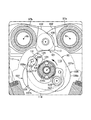
- a first cam 107 for the intake side rocker arm 97a and a second cam 108 for the exhaust side rocker arm 97b are formed on the camshaft 95 between the bearings 106.
- the first cam 107 and the second cam 108 are arranged so as to be shifted in the axial direction of the cam shaft 95.
- the cam follower 101 includes a roller 109 that is supported by the second arm 102 so as to be rotatable about a rotation axis parallel to the axis Xc of the camshaft 95.
- the outer peripheral surface of the roller 109 is in contact with the first cam 107 and the second cam 108, respectively.
- the roller 109 can rotate.
- the roller 109 follows the profiles of the first cam 107 and the second cam 108 while rotating.
- the opening and closing of the intake valve 88 and the exhaust valve 89 are controlled as the roller 109 approaches or moves away from the axis Xc of the camshaft 95.
- the first cam 107 is provided on the camshaft 95 so as to be continuous with the base surface 107a in the rotation direction, and has a base surface 107a having a shape of a partial cylindrical surface coaxial with the axis Xc of the camshaft 95. And a lift surface 107b that rises radially outward and defines the lift amount of the intake valve 88.
- the cam follower 101 of the intake side rocker arm 97a maintains contact with the base surface 107a and the lift surface 107b and causes the intake side rocker arm 97a to swing.
- the second cam 108 is provided on the camshaft 95 continuously to the base surface 108a in the rotational direction and is formed on the camshaft 95 in a rotational direction, and is more than the base surface 108a. And a lift surface 108b that swells radially outward and defines the lift amount of the exhaust valve 89.
- the cam follower 101 of the exhaust side rocker arm 97b maintains the contact with the base surface 108a and the lift surface 108b and causes the exhaust side rocker arm 97b to swing.
- the valve mechanism 97 includes a decompression device 111 according to the first embodiment.
- the decompression device 111 is assembled to the camshaft 95, the decompression cam 112 assembled to the camshaft 95, the decompression follower 113 defined on the exhaust-side rocker arm 97b so as to be in contact with the decompression cam 112, and the camshaft 95.
- the decompression cam 112 and the driving arm 114 are supported by a step surface 115 formed on the camshaft 95 between the second cam 108 and the bearing 106.
- the step surface 115 is partitioned between a large-diameter shaft 116a that defines the second cam 108 and a small-diameter shaft 116b that is continuous with the large-diameter shaft 116a and has a smaller diameter than the large-diameter shaft 116a and is received by the bearing 106, It faces the bearing 106.
- the step surface 115 is connected to the edges of the base surface 108a and the lift surface 108b of the second cam 108 perpendicular to the axis Xc of the cam shaft 95.
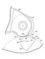
- the decompression cam 112 includes a shaft body 117 having an axis parallel to the axis Xc of the camshaft 95.
- the decompression cam 112 is supported by the camshaft 95 so as to be rotatable about the rotation axis Xd.
- the decompression cam 112 includes a cam body 119 that is coaxial with the shaft body 117.
- the cam body 119 has a cylindrical surface 121 that is concentric with the shaft body 117 and is continuous around the axis of the shaft body 117.
- the cylindrical surface 121 is arranged at a position shifted in the axial direction of the camshaft 95 from the virtual cylindrical surface 122 drawn coaxially with the axis Xc of the camshaft 95 and facing the decompression follower 113.
- the virtual cylindrical surface 122 is a cylindrical surface coaxial with the cylindrical surface 121 and continuous from the cylindrical surface 121 in the axial direction.
- the decompression cam 112 has a cam groove 124 that receives the cam pin 123.
- the cam pin 123 is configured by a cylindrical body having an axis parallel to the axis Xc of the camshaft 95.
- the cam groove 124 is formed on the end surface of the cam body 119 and extends linearly from the cylindrical surface 121 toward the axis.
- the drive arm 114 is supported by the camshaft 95 so as to be swingable about the swing shaft 125.
- the swing shaft 125 has an axis parallel to the axis Xc of the camshaft 95.
- the swing shaft 125 is pushed into the step surface 115 by press-fitting, for example.
- a spacer 126 is mounted on the swing shaft 125 between the step surface 115 and the drive arm 114.
- the size of the spacer 126 in the axial direction of the camshaft 95 corresponds to the size of the virtual cylindrical surface 122.
- the virtual cylindrical surface 122 is disposed between the drive arm 114 and the step surface 115.
- the oscillating shaft 125 is disposed at a position away from the rotational axis Xd of the decompression cam 112 at least in the circumferential direction of the camshaft 95. It is desirable that the swing shaft 125 be separated from the decompression cam 112 as much as possible.
- the rotation axis Xd of the swing shaft 125 and the decompression cam 112 is arranged on both sides of the axis Xc on one diameter line.
- the cam pin 123 is fixed to the tip of the drive arm 114.
- the cam pin 123 moves between a first position that establishes the operating position of the decompression cam 112 and a second position that establishes the non-operating position of the decompression cam 112.
- a torsion spring 127 is attached to the spacer 126.
- One end of the torsion spring 127 is hooked on the drive arm 114.
- the other end of the torsion spring 127 is hooked on the small diameter shaft 116b.
- the torsion spring 127 exhibits an elastic force that drives the cam pin 123 toward the first position.
- the drive arm 114 is curved between the swing shaft 125 and the cam pin 123, bypassing the small diameter shaft 116b.
- a centrifugal weight 128 is attached to the drive arm 114 between the swing shaft 125 and the cam pin 123. The centrifugal weight 128 exerts a centrifugal force that moves the cam pin 123 from the first position to the second position against the elastic force of the torsion spring 127 when the rotation of the camshaft 95 reaches a preset number of rotations.
- the cam body 119 of the decompression cam 112 is disposed in a space inside the virtual cylindrical surface 122, and a partial cylindrical surface 129 that is coaxially continuous with the shaft body 117 from the cylindrical surface 121, and buses at both ends of the partial cylindrical surface 129. And a plane 131 to be connected.
- the decompression cam 112 projects a part of the partial cylindrical surface 129 outward from the virtual cylindrical surface 122 at the operating position.
- the partial cylindrical surface 129 corresponds to a curved projecting surface having a generatrix parallel to the axis Xc of the camshaft 95.
- the decompression follower 113 is provided on the exhaust-side rocker arm 97 b outside the virtual cylindrical surface 122, and faces the virtual cylindrical surface 122 at a position closest to the virtual cylindrical surface 122.
- a convex decompression follower surface 133 having a convex curved surface in contact with the camshaft 95 and a concave curved surface provided upstream of the convex decompression follower surface 133 in the forward rotation direction of the camshaft 95 and having a generatrix parallel to the axis Xc of the camshaft 95.
- a first concave decompression follower surface 134 that is formed and contacts the partial cylindrical surface 129 and a downstream line of the convex decompression follower surface 133 in the forward rotation direction of the camshaft 95, and generates a bus parallel to the axis Xc of the camshaft 95.
- a second concave decompress follower surface 135 that contacts the partial cylindrical surface 129.
- a first auxiliary concave decompression follower surface 136 configured by a concave curved surface having a smaller curvature than the partial cylindrical surface 129 is formed between the convex decompression follower surface 133 and the first concave decompression follower surface 134.
- a second auxiliary concave decompression follower surface 137 is formed between the convex decompression follower surface 133 and the second concave decompression follower surface 135.
- the second auxiliary concave decompression follower surface 137 is a concave curved surface having a smaller curvature than the partial cylindrical surface 129.
- the upstream end 134a of the first concave decompression follower surface 134 is disposed at a position away from the axis Xc of the camshaft 95 in the radial direction as compared with the partial cylindrical surface 129.
- the downstream end 135a of the second concave decompression follower surface 135 is disposed at a position radially away from the axis Xc of the camshaft 95 as compared to the partial cylindrical surface 129.
- the first concave decompression follower surface 134 moves away from the axis Xc of the camshaft 95 as it moves away from the convex decompression follower surface 133 in the circumferential direction of the virtual cylindrical surface 122.
- the second concave decompression follower surface 135 moves away from the axis Xc of the camshaft 95 as it moves away from the convex decompression follower surface 133 in the circumferential direction of the virtual cylindrical surface 122.
- the first concave decompression follower surface 134 is formed by a part of a cylindrical surface having a smaller curvature than the partial cylindrical surface 129.
- the second concave decompression follower surface 135 is formed by a part of a cylindrical surface having a smaller curvature than the partial cylindrical surface 129.
- the first auxiliary concave decompression follower surface 136 is formed by a part of a cylindrical surface having a smaller curvature than the partial cylindrical surface 129.
- the second auxiliary concave decompression follower surface 137 is formed by a part of a cylindrical surface having a smaller curvature than the partial cylindrical surface 129.
- the first auxiliary concave decompression follower surface 136 is formed of a part of a cylindrical surface having a larger curvature than the first concave decompression follower surface 134.
- the second auxiliary concave decompression follower surface 137 is formed of a part of a cylindrical surface having a larger curvature than the second concave decompression follower surface 135.
- the first auxiliary concave decompression follower surface 136 and the second auxiliary concave decompression follower surface 137 may be formed of a part of a cylindrical surface having a smaller curvature than the convex decompression follower surface 133, and have a larger curvature than the convex decompression follower surface 133. You may form with a part of cylindrical surface which has.
- the convex decompression follower surface 133 is further away from the axis Xc of the camshaft 95 than the outer peripheral surface of the roller 109. Since the cylindrical surface 121 and the virtual cylindrical surface 122 have the same diameter, the convex decompression follower surface 133 is maintained at a constant interval from the virtual cylindrical surface 122. As shown in FIG. 7, when the flat surface 131 continuing to the partial cylindrical surface 129 is disposed inside the virtual cylindrical surface 122 at the non-operating position of the decompression cam 112, contact between the decompression cam 112 and the decompression follower 113 is avoided.
- the intake stroke, the compression stroke, the combustion stroke, and the exhaust stroke are repeated in order.
- the intake stroke the intake stroke, the intake valve 88 is opened.
- the piston 45 is lowered by the inertial force of the crankshaft 32.
- An air-fuel mixture is introduced into the combustion chamber 46.
- Fuel is injected from the fuel injection valve 42 by the throttle body 41 into the air introduced from the intake device 37.
- the compression stroke the piston 45 is lifted by the inertial force of the crankshaft 32.
- the intake valve 88 and the exhaust valve 89 are kept closed.
- the air-fuel mixture is compressed in the combustion chamber 46.
- the air-fuel mixture is ignited in the combustion chamber 46.
- the intake valve 88 and the exhaust valve 89 are kept closed.
- the piston 45 descends due to the explosion in the combustion chamber 46.
- a driving force is transmitted to the crankshaft 32.
- the exhaust stroke the exhaust valve 89 is opened.
- the piston 45 is raised by the inertial force of the crankshaft 32.
- the exhaust gas after combustion is released to the exhaust pipe 43.
- the intake stroke is performed again as the piston 45 continues to descend.
- a driving force is transmitted from the alternator starter 49 to the crankshaft 32.
- the AC generator starter 49 generates a driving force in accordance with power supplied from, for example, a battery (not shown).
- the valve mechanism 87 operates in conjunction with the rotation of the crankshaft 32. Opening and closing of the intake valve 88 is controlled by swinging of the intake side rocker arm 97a. The rocker arm 97 a swings according to the contact between the roller 109 and the first cam 107. While the roller 109 is in contact with the base surface 107a of the first cam 107, the rocker arm 97a maintains the closed state of the intake valve 88. When the roller 109 follows the lift surface 107b, the intake valve 88 opens. Opening and closing of the exhaust valve 89 is controlled by swinging of the exhaust side rocker arm 97b. The rocker arm 97 b swings according to the contact between the roller 109 and the second cam 108. While the roller 109 is in contact with the base surface 108 a of the second cam 108, the rocker arm 97 b maintains the exhaust valve 89 in the closed state. When the roller 109 follows the lift surface 108b, the exhaust valve 89 opens.
- the decompression device 111 does not generate sufficient centrifugal force in the centrifugal weight 128 according to the rotation of the camshaft 95. Therefore, the drive arm 114 maintains the cam pin 123 in the first position according to the elastic force of the torsion spring 127.
- the decompression cam 112 is located at the operating position.
- the partial cylindrical surface 129 protrudes from the virtual cylindrical surface including the virtual cylindrical surface 122.
- the partial cylindrical surface 129 becomes the first concave decompression follower surface 134, the first auxiliary concave decompression follower surface 136, the convex decompression follower surface 133, the second auxiliary concave decompression follower surface 137 and the first auxiliary concave decompression follower surface 137.
- the two-concave decompressor follower surface 135 is successively contacted.
- the exhaust valve 89 opens during the compression stroke.
- the pressure in the combustion chamber 46 is released.
- the driving resistance of the piston 45 is reduced, and the vibration of the internal combustion engine is suppressed.
- the decompression device 111 When the engine speed of the internal combustion engine 29 reaches or exceeds a predetermined speed, the decompression device 111 generates a sufficient centrifugal force in the centrifugal weight 128 according to the rotation of the camshaft 95. Therefore, the drive arm 114 drives the cam pin 123 from the first position to the second position against the elastic force of the torsion spring 127.
- the decompression cam 112 changes its posture to the non-operating position.
- the decompression cam 112 fits inside the virtual cylindrical surface including the virtual cylindrical surface 122. Contact between the decompression follower 113 and the decompression cam 112 during the rotation of the camshaft 95 is avoided.
- the exhaust valve 89 is kept closed during the compression stroke. The driving force of the piston 45 based on the explosion is maximized.
- the internal combustion engine 29 generates power efficiently.
- the partial cylindrical surface 129 of the decompression cam 112 protrudes in the centrifugal direction of the camshaft 95 in a low rotational speed range less than the set rotational speed.
- the partial cylindrical surface 129 of the decompression cam 112 successively contacts the first concave decompression follower surface 134 and the convex decompression follower surface 133 of the exhaust side rocker arm 97b. Since the first concave decompression follower surface 134 is formed as a concave curved surface, the partial cylindrical surface 129 of the decompression cam 112 can slide in a tangential direction with respect to the concave curved surface at the start of contact. Therefore, the collision sound between the decompression cam 112 and the exhaust side rocker arm 97b can be suppressed.
- the upstream end 134a of the first concave decompression follower surface 134 is disposed at a position farther from the axis Xc of the camshaft 95 than the partial cylindrical surface 129 of the rocker arm 97b.
- the partial cylindrical surface 129 of the decompression cam 112 reliably contacts the concave curved surface of the first concave decompression follower surface 134.
- the collision sound between the decompression cam 112 and the exhaust side rocker arm 97b can be suppressed.
- the first concave decompression follower surface 134 moves away from the axis Xc of the camshaft 95 as the distance from the convex decompression follower surface 133 increases. Therefore, even if the partial cylindrical surface 129 of the decompression cam 112 is slightly displaced based on dimensional tolerances or assembly errors, the partial cylindrical surface 129 of the decompression cam 112 is tangential to the first concave decompression follower surface 134 at the start of contact. You can slide into. Therefore, the collision sound between the decompression cam 112 and the exhaust side rocker arm 97b can be suppressed.
- the first auxiliary concave decompression follower configured by a concave curved surface having a smaller curvature than the partial cylindrical surface 129 of the decompression cam 112 between the convex decompression follower surface 133 and the first concave decompression follower surface 134.
- a surface 136 is formed. Since the first concave decompression follower surface 134, the first auxiliary concave decompression follower surface 136 and the convex decompression follower surface 133 are continuous, the partial cylindrical surface 129 of the decompression cam 112 is changed from the first concave decompression follower surface 134 to the convex decompression follower surface 133. It can follow smoothly. The collision sound between the decompression cam 112 and the exhaust side rocker arm 97b can be suppressed.
- the first auxiliary concave decompression follower surface 136 is formed by a part of a cylindrical surface having a larger curvature than the first concave decompression follower surface 134.
- the partial cylindrical surface 129 of the decompression cam 112 smoothly follows the convex decompression follower surface 133 from the first concave decompression follower surface 134 in accordance with the change in curvature.
- the collision sound between the decompression cam 112 and the exhaust side rocker arm 97b can be suppressed.
- the partial cylindrical surface 129 of the decompression cam 112 contacts the second concave decompression follower surface 135 following the convex decompression follower surface 133. Since the second concave decompression follower surface 135 is formed as a concave curved surface, the lift amount of the exhaust valve 89 gradually changes when the decompression cam 112 is detached from the second concave decompression follower surface 135. As a result, the seating sound (seat noise) of the exhaust valve 89 is reduced.
- the partial cylindrical surface 129 of the decompression cam 112 successively contacts the second concave decompression follower surface 135 and the convex decompression follower surface 133 when the piston 45 does not pass over the compression top dead center and the camshaft 95 reverses. Since the second concave decompression follower surface 135 is formed as a concave curved surface, the partial cylindrical surface 129 of the decompression cam 112 can slide in a tangential direction with respect to the concave curved surface at the start of contact. Therefore, when the camshaft 95 reverses without the piston 45 overcoming the compression top dead center, the collision noise between the decompression cam 112 and the exhaust-side rocker arm 97b can be suppressed.
- the downstream end 135a of the second concave decompression follower surface 135 is disposed at a position farther from the axis Xc of the camshaft 95 than the partial cylindrical surface 129 of the decompression cam 112.
- the partial cylindrical surface 129 of the decompression cam 112 moves away from the rocker arm 97b with a concave curved surface.
- the lift amount of the exhaust valve 89 changes gradually.
- the seating noise of the exhaust valve 89 can be reduced.
- the second concave decompression follower surface 135 moves away from the axis Xc of the camshaft 95 as the distance from the convex decompression follower surface 133 increases. Therefore, even if the partial cylindrical surface 129 of the decompression cam 112 is slightly displaced based on dimensional tolerances, assembly errors, etc., the lift amount of the exhaust valve 89 changes gently upon seating. Thus, the seating noise of the exhaust valve 89 can be reduced.
- a second auxiliary concave decompression follower surface 137 configured by a concave curved surface having a smaller curvature than the partial cylindrical surface 129 of the decompression cam 112 is provided between the convex decompression follower surface 133 and the second concave decompression follower surface 135. It is formed. Since the convex decompression follower surface 133, the second auxiliary concave decompression follower surface 137, and the second concave decompression follower surface 135 are continuous, the partial cylindrical surface 129 of the decompression cam 112 changes from the convex decompression follower surface 133 to the second concave decompression follower surface 135. It can follow smoothly. The collision sound between the decompression cam 112 and the exhaust side rocker arm 97b can be suppressed.
- the second auxiliary concave decompression follower surface 137 is formed by a part of a cylindrical surface having a larger curvature than the second concave decompression follower surface 135.
- the partial cylindrical surface 129 of the decompression cam 112 can smoothly follow the second concave decompression follower surface 135 from the convex decompression follower surface 133 in accordance with the change in curvature.
- the collision sound between the decompression cam 112 and the exhaust side rocker arm 97b can be suppressed.
- the internal combustion engine 29 employs motor idling control.
- fuel is not injected from the fuel injection valve 42 into the air introduced from the intake device 37 into the combustion chamber 46 when the accelerator is off (the accelerator is not operated).
- a driving force is transmitted from the alternator starter 49 to the crankshaft 32 in maintaining idling.
- the AC generator starter 49 generates a driving force in accordance with power supplied from, for example, a battery (not shown).
- the AC generator starter 49 can realize the reciprocating motion of the piston 45 without going through a combustion stroke. Fuel consumption is suppressed and the exhaust noise of the internal combustion engine 29 is reduced.
- FIG. 8 schematically shows the configuration of the decompression device 141 according to the second embodiment.
- the decompression follower 142 includes the first concave decompression follower surface 134, the first auxiliary concave decompression follower surface 136, the convex decompression follower surface 133, the second auxiliary concave decompression follower surface 137, and the second concave decompression follower surface.
- a convex decompression follower surface 143 having a single convex curved surface is provided.
- the curved projecting surface 145 of the decompression cam 144 is provided upstream of the top surface 146 that protrudes most from the virtual cylindrical surface 122 and the top surface 146 in the forward rotation direction of the camshaft 95, and the axis Xc of the camshaft 95.
- a second buffer surface 148 formed on the concave curved surface.
- Other configurations are the same as those of the above-described embodiment.
- the convex decompression follower surface 143 of the decompression follower 142 is constituted by a part of a cylindrical surface that is coaxial with the rotation axis of the roller 109 and has a smaller diameter than the roller 109. Therefore, the convex decompression follower surface 143 faces the virtual cylindrical surface 122 at a set interval.
- the top surface 146 of the decompression cam 144 is configured as a part of a cylindrical surface having the same diameter as the partial cylindrical surface 129.
- the first buffer surface 147 and the second buffer surface 148 of the decompression cam 144 are each formed of a partial cylindrical surface having a smaller curvature than the convex decompression follower surface 143.
- the upstream end 147a of the first buffer surface 147 is disposed at a position closer to the axis Xc of the camshaft 95 than the convex decompression follower surface 143 when the decompression cam 144 is located at the operating position.
- the downstream end 148a of the second buffer surface 148 is disposed closer to the axis Xc of the camshaft 95 than the convex decompression follower surface 143 when the decompression cam 144 is located at the operating position.
- the curved projecting surface 145 of the decompression cam 144 successively contacts the convex decompression follower surface 143 of the exhaust-side rocker arm 97b at the first buffer surface 147 and the top surface 146. Since the first buffer surface 147 of the decompression cam 144 is formed in a concave curved surface, the convex decompression follower surface 143 can slide in a tangential direction with respect to the first buffer surface 147 of the decompression cam 144 at the start of contact. Therefore, the collision sound between the decompression cam 144 and the exhaust side rocker arm 97b can be suppressed.
- the curved projection surface 145 of the decompression cam 144 contacts the convex decompression follower surface 143 at the second buffer surface 148 following the top surface 146. Since the second buffer surface 148 is formed as a concave curved surface, when the convex decompression follower surface 143 is detached from the second buffer surface 148, the lift amount of the exhaust valve 89 gradually changes. As a result, the seating sound (seat noise) of the exhaust valve 89 is reduced. Moreover, during the reverse rotation of the camshaft 95, the curved projecting surface 145 of the decompression cam 144 contacts the second buffer surface 148 and the top surface 146 one after another.
- the convex decompression follower surface 143 can slide in the tangential direction with respect to the second buffer surface 148 at the start of contact. Therefore, when the piston 45 does not pass over the compression top dead center and the camshaft 95 is reversed, the collision noise between the decompression cam 144 and the exhaust-side rocker arm 97b can be suppressed.
- FIG. 9 schematically shows a configuration of a decompression device 151 according to the third embodiment.
- the cam follower 101 also serves as the decompression follower 142. That is, the roller 109 of the cam follower 101 functions as the convex decompression follower surface 143 having the above-described convex curved surface over the entire circumference of the cylindrical surface.
- the roller 109 faces the virtual cylindrical surface 122 at a set interval.
- the top surface 146 of the decompression cam 144 is configured as a part of a cylindrical surface having the same diameter as the partial cylindrical surface 129.
- the first buffer surface 147 and the second buffer surface 148 of the decompression cam 144 are each configured by a partial cylindrical surface having a smaller curvature than the cylindrical surface of the roller 109.
- the upstream end 147a of the first buffer surface 147 is disposed at a position closer to the axis Xc of the camshaft 95 than the roller 109 when the decompression cam 144 is positioned at the operating position.
- the downstream end 148a of the second buffer surface 148 is disposed at a position closer to the axis Xc of the camshaft 95 than the roller 109 when the decompression cam 144 is positioned at the operating position.
- Other configurations are the same as those of the second embodiment.
- the curved projecting surface 145 of the decompression cam 144 successively contacts the roller 109 of the exhaust-side rocker arm 97b at the first buffer surface 147 and the top surface 146. Since the first buffer surface 147 of the decompression cam 144 is formed in a concave curved surface, the roller 109 can slide in the tangential direction with respect to the first buffer surface 147 of the decompression cam 144 at the start of contact. Therefore, the collision sound between the decompression cam 144 and the exhaust side rocker arm 97b can be suppressed.
- the curved projection surface 145 of the decompression cam 144 comes into contact with the roller 109 at the second buffer surface 148 following the top surface 146. Since the second buffer surface 148 is formed in a concave curved surface, when the roller 109 is detached from the second buffer surface 148, the lift amount of the exhaust valve 89 gradually changes. As a result, the seating sound (seat noise) of the exhaust valve 89 is reduced. Moreover, during the reverse rotation of the camshaft 95, the curved projecting surface 145 of the decompression cam 144 contacts the second buffer surface 148 and the top surface 146 one after another.
- the roller 109 can slide in the tangential direction with respect to the second buffer surface 148 at the start of contact. Therefore, when the piston 45 does not pass over the compression top dead center and the camshaft 95 is reversed, the collision noise between the decompression cam 144 and the exhaust-side rocker arm 97b can be suppressed.
Abstract
Provided is an internal combustion engine that comprises: a decompression cam (112) that causes a curved protruding surface (129), which has a generating line that is parallel to a rotational axis of a cam shaft, to protrude from an imaginary cylindrical surface (122), which is coaxial with the camshaft, at a rotational speed less than a preset rotational speed; a convex decompression follower surface (133) that is a convex curved surface that is provided on an exhaust-side rocker arm (97b) outside the imaginary cylindrical surface (122), and that faces the imaginary cylindrical surface (122) and contacts the curved protruding surface (129) at a position closest to the imaginary cylindrical surface (122); and a concave decompression follower surface (134) that is provided upstream from the convex decompression follower surface (133) in the positive rotation direction of the camshaft, that is formed into a concave curved surface having a generating line that is parallel to the rotational axis of the camshaft, and that contacts the curved protruding surface (129). Due to this configuration, provided is an internal combustion engine that can further reduce a collision sound between a decompression cam and an exhaust-side rocker arm and a seat sound of an exhaust valve.
Description
本発明は内燃機関のデコンプ装置に関する。
The present invention relates to a decompression device for an internal combustion engine.
特許文献1は内燃機関のデコンプ装置を開示する。デコンプ装置は、カムシャフトの回転軸線に平行な軸心を有する小径の部分円筒面を有するデコンプカムを備える。デコンプカムは、予め設定された回転数未満で、カムシャフトに同軸の仮想円筒面よりも部分円筒面の一部を突出させる。排気側ロッカーアームのスリッパーは突出するデコンプカムに接触して排気弁を開く。低回転域で圧縮行程中に排気弁が開くことで、ピストンの駆動抵抗が軽減され、内燃機関の振動は抑制される。
Patent Document 1 discloses a decompression device for an internal combustion engine. The decompression device includes a decompression cam having a small-diameter partial cylindrical surface having an axis parallel to the rotation axis of the camshaft. The decompression cam causes a part of the partial cylindrical surface to protrude from the virtual cylindrical surface coaxial with the camshaft at a rotation speed less than a preset value. The slipper of the exhaust side rocker arm contacts the protruding decompression cam and opens the exhaust valve. By opening the exhaust valve during the compression stroke in the low rotation range, the driving resistance of the piston is reduced and the vibration of the internal combustion engine is suppressed.
ピストンが圧縮上死点を乗り越えきらずカムシャフトが逆転する際に、デコンプカムと排気側ロッカーアームとの衝突音は低減される。こうした衝突音の低減だけでなく、カムシャフトの正転時に、デコンプカムと排気側ロッカーアームとの衝突音や排気弁の着座音の低減が要求される。
¡When the piston rotates over the compression top dead center and the camshaft reverses, the collision noise between the decompression cam and the exhaust side rocker arm is reduced. In addition to reducing the impact noise, it is required to reduce the impact noise between the decompression cam and the exhaust side rocker arm and the seating noise of the exhaust valve when the camshaft rotates forward.
本発明は、上記実状に鑑みてなされたもので、デコンプカムと排気側ロッカーアームとの衝突音や排気弁の着座音をさらに低減することができる内燃機関を提供することを目的とする。
The present invention has been made in view of the above circumstances, and an object thereof is to provide an internal combustion engine that can further reduce the collision noise between the decompression cam and the exhaust-side rocker arm and the seating noise of the exhaust valve.
本発明の第1側面によれば、カムシャフトの回転軸線に同軸の部分円筒面の形状を有するベース面と、回転方向に前記ベース面に連続して前記カムシャフトに設けられて、前記ベース面よりも径方向外方に盛り上がって排気弁のリフト量を規定するリフト面と、排気側ロッカーアームに設けられて、前記ベース面および前記リフト面との接触を維持して前記排気側ロッカーアームの揺動を引き起こすカムフォロワーと、予め設定された回転数未満で、前記カムシャフトに同軸の仮想円筒面から、前記カムシャフトの回転軸線に平行な母線を有する湾曲突面を突出させるデコンプカムと、前記仮想円筒面の外側で前記排気側ロッカーアームに設けられて、前記仮想円筒面に最も近い位置で前記仮想円筒面に向き合って前記湾曲突面に接触する凸湾曲面の凸デコンプフォロワー面と、前記カムシャフトの正転方向に前記凸デコンプフォロワー面の上流に設けられて、前記カムシャフトの回転軸線に平行な母線を有する凹湾曲面に形成されて前記湾曲突面に接触する凹デコンプフォロワー面とを備える内燃機関は提供される。
According to the first aspect of the present invention, a base surface having a shape of a partial cylindrical surface coaxial with the rotation axis of the camshaft, and the base surface is provided on the camshaft continuously to the base surface in the rotation direction. A lift surface that swells outward in the radial direction and defines the lift amount of the exhaust valve, and an exhaust-side rocker arm that maintains contact with the base surface and the lift surface to maintain the exhaust-side rocker arm. A cam follower that causes rocking, a decompression cam that projects a curved projecting surface having a generatrix parallel to the rotational axis of the camshaft from a virtual cylindrical surface that is coaxial with the camshaft and is less than a preset number of revolutions, and Provided on the exhaust-side rocker arm outside the virtual cylindrical surface, facing the virtual cylindrical surface at a position closest to the virtual cylindrical surface and contacting the curved projecting surface A curved convex convex follower surface and a concave curved surface provided in the forward rotation direction of the camshaft and upstream of the convex decompression follower surface and having a generatrix parallel to the rotational axis of the camshaft. An internal combustion engine is provided that includes a concave decompressor follower surface that contacts the projecting surface.
第2側面によれば、第1側面の構成に加えて、前記凹デコンプフォロワー面の上流端は、前記湾曲突面に比べて前記カムシャフトの回転軸線から離れた位置に設けられる。
According to the second side surface, in addition to the configuration of the first side surface, the upstream end of the concave decompression follower surface is provided at a position farther from the rotational axis of the camshaft than the curved projecting surface.
第3側面によれば、第1または第2側面の構成に加えて、前記凹デコンプフォロワー面は、前記凸デコンプフォロワー面から遠ざかるにつれて前記カムシャフトの回転軸線から遠ざかる。
According to the third aspect, in addition to the configuration of the first or second side surface, the concave decompression follower surface moves away from the rotation axis of the camshaft as the distance from the convex decompression follower surface increases.
第4側面によれば、第1~第3側面のいずれかの構成に加えて、内燃機関は、前記凸デコンプフォロワー面および前記凹デコンプフォロワー面の間に形成されて、前記湾曲突面よりも小さい曲率の凹湾曲面で構成される補助凹デコンプフォロワー面をさらに備える。
According to the fourth aspect, in addition to the configuration of any one of the first to third aspects, the internal combustion engine is formed between the convex decompression follower surface and the concave decompression follower surface, and more than the curved projecting surface. An auxiliary concave decompressor follower surface composed of a concave curved surface having a small curvature is further provided.
第5側面によれば、第4側面の構成に加えて、前記補助凹デコンプフォロワー面は、前記凹デコンプフォロワー面よりも大きい曲率を有する円筒面の一部で形成される。
According to the fifth aspect, in addition to the configuration of the fourth side surface, the auxiliary concave decompression follower surface is formed by a part of a cylindrical surface having a larger curvature than the concave decompression follower surface.
第6側面によれば、第1~第5側面のいずれかの構成に加えて、内燃機関は、前記カムシャフトの正転方向に前記凸デコンプフォロワー面の下流に設けられて、前記カムシャフトの回転軸線に平行な母線を有する凹湾曲面に形成されて前記湾曲突面に接触する第2の凹デコンプフォロワー面をさらに備える。
According to the sixth aspect, in addition to the configuration of any one of the first to fifth aspects, the internal combustion engine is provided downstream of the convex decompression follower surface in the forward rotation direction of the camshaft, It further includes a second concave decompression follower surface that is formed on a concave curved surface having a generatrix parallel to the rotation axis and contacts the curved convex surface.
第7側面によれば、カムシャフトの回転軸線に同軸の部分円筒面の形状を有するベース面と、回転方向に前記ベース面に連続して前記カムシャフトに設けられて、前記ベース面よりも径方向外方に盛り上がって排気弁のリフト量を規定するリフト面と、排気側ロッカーアームに設けられて、前記ベース面および前記リフト面との接触を維持して前記排気側ロッカーアームの揺動を引き起こすカムフォロワーと、予め設定された回転数未満で、前記カムシャフトに同軸の仮想円筒面から、前記カムシャフトの回転軸線に平行な母線を有する湾曲突面を突出させるデコンプカムと、前記仮想円筒面の外側で前記排気側ロッカーアームに設けられて、前記仮想円筒面に最も近い位置で前記仮想円筒面に向き合って前記湾曲突面に接触する凸デコンプフォロワー面と、前記カムシャフトの正転方向に前記凸デコンプフォロワー面の下流に設けられて、前記カムシャフトの回転軸線に平行な母線を有する凹湾曲面に形成されて前記湾曲突面に接触する凹デコンプフォロワー面とを備える内燃機関は提供される。
According to the seventh aspect, the base surface having a shape of a partial cylindrical surface coaxial with the rotation axis of the camshaft, and the camshaft is provided on the camshaft continuously to the base surface in the rotation direction, and has a diameter larger than that of the base surface. A lift surface that swells outward in the direction and defines the lift amount of the exhaust valve, and an exhaust-side rocker arm that maintains contact with the base surface and the lift surface to swing the exhaust-side rocker arm. A cam follower, a decompression cam projecting a curved projecting surface having a generatrix parallel to the rotation axis of the camshaft from a virtual cylindrical surface coaxial with the camshaft at a rotation speed less than a preset rotational speed, and the virtual cylindrical surface A convex decon that is provided on the exhaust-side rocker arm on the outer side and contacts the curved projecting surface facing the virtual cylindrical surface at a position closest to the virtual cylindrical surface A follower surface is provided downstream of the convex decompression follower surface in the forward rotation direction of the camshaft, and is formed as a concave curved surface having a generatrix parallel to the rotation axis of the camshaft and contacts the curved projecting surface An internal combustion engine having a concave decompressor follower surface is provided.
第8側面によれば、第7側面の構成に加えて、前記凹デコンプフォロワー面の下流端は、前記湾曲突面に比べて前記カムシャフトの回転軸線から離れた位置に設けられる。
According to the eighth aspect, in addition to the configuration of the seventh side surface, the downstream end of the concave decompression follower surface is provided at a position farther from the rotational axis of the camshaft than the curved projecting surface.
第9側面によれば、第7または第8側面の構成に加えて、前記凹デコンプフォロワー面は、前記凸デコンプフォロワー面から遠ざかるにつれて前記カムシャフトの回転軸線から遠ざかる。
According to the ninth aspect, in addition to the configuration of the seventh or eighth aspect, the concave decompression follower surface is further away from the rotational axis of the camshaft as the distance from the convex decompression follower surface is increased.
第10側面によれば、第7~第9側面のいずれかの構成に加えて、内燃機関は、前記凸デコンプフォロワー面および前記凹デコンプフォロワー面の間に形成されて、前記湾曲突面よりも小さい曲率の凹湾曲面で構成される補助凹デコンプフォロワー面をさらに備える。
According to the tenth aspect, in addition to the configuration of any one of the seventh to ninth aspects, the internal combustion engine is formed between the convex decompression follower surface and the concave decompression follower surface, and more than the curved projecting surface. An auxiliary concave decompressor follower surface composed of a concave curved surface having a small curvature is further provided.
第11側面によれば、第10側面の構成に加えて、前記補助凹デコンプフォロワー面は、前記凹デコンプフォロワー面よりも大きい曲率を有する円筒面の一部で形成される。
According to the eleventh aspect, in addition to the configuration of the tenth side surface, the auxiliary concave decompression follower surface is formed by a part of a cylindrical surface having a larger curvature than the concave decompression follower surface.
第12側面によれば、第1~第11側面のいずれかの構成に加えて、内燃機関は、クランクシャフトに結合されて、前記クランクシャフトの回転に応じて発電するとともに、供給される電力に応じて前記クランクシャフトをその回転軸線回りに駆動する交流発電機をさらに備える。
According to the twelfth aspect, in addition to the structure of any one of the first to eleventh aspects, the internal combustion engine is coupled to the crankshaft and generates electric power in accordance with the rotation of the crankshaft, and the supplied electric power. Accordingly, an AC generator for driving the crankshaft around its rotational axis is further provided.
第13側面によれば、カムシャフトの回転軸線に同軸の部分円筒面の形状を有するベース面と、回転方向に前記ベース面に連続して前記カムシャフトに設けられて、前記ベース面よりも径方向外方に盛り上がって排気弁のリフト量を規定するリフト面と、排気側ロッカーアームに設けられて、前記ベース面および前記リフト面との接触を維持して前記排気側ロッカーアームの揺動を引き起こすカムフォロワーと、予め設定された回転数未満で、前記カムシャフトに同軸の仮想円筒面から、前記カムシャフトの回転軸線に平行な母線を有する湾曲突面を突出させるデコンプカムと、前記仮想円筒面の外側で前記排気側ロッカーアームに設けられて、前記仮想円筒面に向き合って前記湾曲突面に接触する凸湾曲面の凸デコンプフォロワー面とを備え、前記湾曲突面は、前記仮想円筒面から最も突出する頂上面と、前記カムシャフトの正転方向に前記頂上面の上流に設けられて、前記カムシャフトの回転軸線に平行な母線を有する凹湾曲面に形成されて前記凸デコンプフォロワー面に接触する緩衝面とを有する内燃機関は提供される。
According to the thirteenth aspect, a base surface having a shape of a partial cylindrical surface coaxial with the rotation axis of the camshaft, and provided on the camshaft continuously to the base surface in the rotation direction, the diameter is larger than the base surface. A lift surface that swells outward in the direction and defines the lift amount of the exhaust valve, and an exhaust-side rocker arm that maintains contact with the base surface and the lift surface to swing the exhaust-side rocker arm. A cam follower, a decompression cam projecting a curved projecting surface having a generatrix parallel to the rotation axis of the camshaft from a virtual cylindrical surface coaxial with the camshaft at a rotation speed less than a preset rotational speed, and the virtual cylindrical surface A convex decompression follower surface of the convex curved surface that is provided on the exhaust-side rocker arm on the outer side and faces the virtual cylindrical surface and contacts the curved convex surface. The curved projecting surface has a top surface that protrudes most from the virtual cylindrical surface, and a generatrix that is provided upstream of the top surface in the forward rotation direction of the camshaft and is parallel to the rotation axis of the camshaft. There is provided an internal combustion engine having a buffer surface formed on a concave curved surface and contacting the convex decompression follower surface.
第14側面によれば、第13側面の構成に加えて、前記湾曲突面は、前記カムシャフトの正転方向に前記頂上面の下流に設けられて、前記カムシャフトの回転軸線に平行な母線を有する凹湾曲面に形成される第2の緩衝面をさらに有する。
According to the fourteenth aspect, in addition to the configuration of the thirteenth side surface, the curved projecting surface is provided downstream of the top surface in the normal rotation direction of the camshaft and is parallel to the rotation axis of the camshaft. And a second buffer surface formed on the concave curved surface.
第15側面によれば、カムシャフトの回転軸線に同軸の部分円筒面の形状を有するベース面と、回転方向に前記ベース面に連続して前記カムシャフトに設けられて、前記ベース面よりも径方向外方に盛り上がって排気弁のリフト量を規定するリフト面と、排気側ロッカーアームに設けられて、前記ベース面および前記リフト面との接触を維持して前記排気側ロッカーアームの揺動を引き起こすカムフォロワーと、予め設定された回転数未満で、前記カムシャフトに同軸の仮想円筒面から、前記カムシャフトの回転軸線に平行な母線を有する湾曲突面を突出させるデコンプカムと、前記仮想円筒面の外側で前記排気側ロッカーアームに設けられて、前記仮想円筒面に向き合って前記湾曲突面に接触する凸湾曲面の凸デコンプフォロワー面とを備え、前記湾曲突面は、前記仮想円筒面から最も突出する頂上面と、前記カムシャフトの正転方向に前記頂上面の下流に設けられて、前記カムシャフトの回転軸線に平行な母線を有する凹湾曲面に形成されて前記凸デコンプフォロワー面に接触する緩衝面とを有する内燃機関は提供される。
According to the fifteenth aspect, the base surface having the shape of a partial cylindrical surface coaxial with the rotation axis of the camshaft, and the camshaft is provided on the camshaft continuously to the base surface in the rotation direction, and has a diameter larger than that of the base surface. A lift surface that swells outward in the direction and defines the lift amount of the exhaust valve, and an exhaust-side rocker arm that maintains contact with the base surface and the lift surface to swing the exhaust-side rocker arm. A cam follower, a decompression cam projecting a curved projecting surface having a generatrix parallel to the rotation axis of the camshaft from a virtual cylindrical surface coaxial with the camshaft at a rotation speed less than a preset rotational speed, and the virtual cylindrical surface A convex decompression follower surface of the convex curved surface that is provided on the exhaust-side rocker arm on the outer side and faces the virtual cylindrical surface and contacts the curved convex surface. The curved projecting surface has a top surface that protrudes most from the virtual cylindrical surface and a generatrix that is provided downstream of the top surface in the normal rotation direction of the camshaft and is parallel to the rotation axis of the camshaft. There is provided an internal combustion engine having a buffer surface formed on a concave curved surface and contacting the convex decompression follower surface.
第1側面によれば、設定された回転数未満の低回転域ではデコンプカムの湾曲突面がカムシャフトの遠心方向に突出する。カムシャフトの正転中、デコンプカムの湾曲突面は排気側ロッカーアームの凹デコンプフォロワー面および凸デコンプフォロワー面に相次いで接触する。凹デコンプフォロワー面は凹湾曲面に形成されることから、接触の開始にあたってデコンプカムの湾曲突面は凹湾曲面に対して接線方向に滑ることができる。したがって、デコンプカムと排気側ロッカーアームとの衝突音は抑制されることができる。
According to the first aspect, the curved protrusion surface of the decompression cam protrudes in the centrifugal direction of the camshaft in a low rotation range less than the set rotation speed. During forward rotation of the camshaft, the curved protrusion surface of the decompression cam contacts the concave decompression follower surface and the convex decompression follower surface of the exhaust side rocker arm one after another. Since the concave decompression follower surface is formed into a concave curved surface, the curved convex surface of the decompression cam can slide in a tangential direction with respect to the concave curved surface at the start of contact. Therefore, the collision sound between the decompression cam and the exhaust side rocker arm can be suppressed.
第2側面によれば、接触の開始にあたって、デコンプカムの湾曲突面は凹湾曲面に接触する。デコンプカムと排気側ロッカーアームとの衝突音は抑制されることができる。
According to the second aspect, at the start of contact, the curved protrusion surface of the decompression cam contacts the concave curved surface. The collision noise between the decompression cam and the exhaust side rocker arm can be suppressed.
第3側面によれば、寸法公差や組み立て誤差などに基づいてデコンプカムの湾曲突面が多少位置ずれしても、接触の開始にあたってデコンプカムの湾曲突面は凹湾曲面に対して接線方向に滑ることができる。したがって、デコンプカムと排気側ロッカーアームとの衝突音は抑制されることができる。
According to the third aspect, even if the curved surface of the decompression cam is slightly displaced due to dimensional tolerances or assembly errors, the curved surface of the decompression cam slides in the tangential direction with respect to the concave curved surface at the start of contact. Can do. Therefore, the collision sound between the decompression cam and the exhaust side rocker arm can be suppressed.
第4側面によれば、凹デコンプフォロワー面、補助凹デコンプフォロワー面および凸デコンプフォロワー面は連続することから、デコンプカムの湾曲突面は凹デコンプフォロワー面から凸デコンプフォロワー面にスムースに追従することができる。デコンプカムと排気側ロッカーアームとの衝突音は抑制されることができる。
According to the fourth aspect, since the concave decompression follower surface, the auxiliary concave decompression follower surface and the convex decompression follower surface are continuous, the curved convex surface of the decompression cam can smoothly follow the convex decompression follower surface from the concave decompression follower surface. it can. The collision noise between the decompression cam and the exhaust side rocker arm can be suppressed.
第5側面によれば、曲率の変化に応じてデコンプカムの湾曲突面は凹デコンプフォロワー面から凸デコンプフォロワー面にスムースに追従することができる。デコンプカムと排気側ロッカーアームとの衝突音は抑制されることができる。
According to the fifth aspect, the curved protrusion surface of the decompression cam can smoothly follow the convex decompression follower surface from the concave decompression follower surface in accordance with the change in curvature. The collision noise between the decompression cam and the exhaust side rocker arm can be suppressed.
第6側面によれば、カムシャフトの正転中、デコンプカムの湾曲突面は凸デコンプフォロワー面に続いて第2の凹デコンプフォロワー面に接触する。第2の凹デコンプフォロワー面は凹湾曲面に形成されることから、第2の凹デコンプフォロワー面からデコンプカムが離脱する際に、排気弁のリフト量は緩やかに変化する。その結果、排気弁の着座音(シーティング音)は低減される。しかも、カムシャフトの逆転中、デコンプカムの湾曲突面は第2の凹デコンプフォロワー面および凸デコンプフォロワー面に相次いで接触する。第2の凹デコンプフォロワー面は凹湾曲面に形成されることから、接触の開始にあたってデコンプカムの湾曲突面は凹湾曲面に対して接線方向に滑ることができる。したがって、ピストンが圧縮上死点を乗り越えきらずカムシャフトが逆転する際に、デコンプカムと排気側ロッカーアームとの衝突音は抑制されることができる。
According to the sixth aspect, during the forward rotation of the camshaft, the curved convex surface of the decompression cam contacts the second concave decompression follower surface following the convex decompression follower surface. Since the second concave decompression follower surface is formed as a concave curved surface, the lift amount of the exhaust valve changes gently when the decompression cam is detached from the second concave decompression follower surface. As a result, the seating sound of the exhaust valve is reduced. In addition, during the reverse rotation of the camshaft, the curved protrusion surface of the decompression cam successively contacts the second concave decompression follower surface and the convex decompression follower surface. Since the second concave decompression follower surface is formed into a concave curved surface, the curved convex surface of the decompression cam can slide in a tangential direction with respect to the concave curved surface at the start of contact. Therefore, when the camshaft reverses without overcoming the compression top dead center, the collision noise between the decompression cam and the exhaust-side rocker arm can be suppressed.
第7側面によれば、カムシャフトの正転中、デコンプカムの湾曲突面は凸デコンプフォロワー面に続いて凹デコンプフォロワー面に接触する。凹デコンプフォロワー面は凹湾曲面に形成されることから、凹デコンプフォロワーからデコンプカムが離脱する際に、排気弁のリフト量は緩やかに変化する。その結果、排気弁の着座音(シーティング音)は低減される。しかも、カムシャフトの逆転中、デコンプカムの湾曲突面は凹デコンプフォロワー面および凸デコンプフォロワー面に相次いで接触する。凹デコンプフォロワー面は凹湾曲面に形成されることから、接触の開始にあたってデコンプカムの湾曲突面は凹湾曲面に対して接線方向に滑ることができる。したがって、ピストンが圧縮上死点を乗り越えきらずカムシャフトが逆転する際に、デコンプカムと排気側ロッカーアームとの衝突音は抑制されることができる。
According to the seventh aspect, during the forward rotation of the camshaft, the curved protrusion surface of the decompression cam contacts the concave decompression follower surface following the convex decompression follower surface. Since the concave decompression follower surface is formed as a concave curved surface, the lift amount of the exhaust valve changes gently when the decompression cam is detached from the concave decompression follower. As a result, the seating sound of the exhaust valve is reduced. In addition, during the reverse rotation of the camshaft, the curved protrusion surface of the decompression cam contacts the concave decompression follower surface and the convex decompression follower surface one after another. Since the concave decompression follower surface is formed into a concave curved surface, the curved convex surface of the decompression cam can slide in a tangential direction with respect to the concave curved surface at the start of contact. Therefore, when the camshaft reverses without overcoming the compression top dead center, the collision noise between the decompression cam and the exhaust-side rocker arm can be suppressed.
第8側面によれば、カムシャフトの回転に応じて、デコンプカムの湾曲突面は凹湾曲面でロッカーアームから離れる。着座にあたって排気弁のリフト量は確実に緩やかに変化する。こうして排気弁の着座音は低減されることができる。
According to the eighth aspect, according to the rotation of the camshaft, the curved projecting surface of the decompression cam separates from the rocker arm with a concave curved surface. When lifted, the lift amount of the exhaust valve surely changes slowly. Thus, the seating noise of the exhaust valve can be reduced.
第9側面によれば、寸法公差や組み立て誤差などに基づいてデコンプカムの湾曲突面が多少位置ずれしても、着座にあたって排気弁のリフト量は緩やかに変化する。こうして排気弁の着座音は低減されることができる。
According to the ninth aspect, the lift amount of the exhaust valve changes gently when seated even if the curved protrusion surface of the decompression cam is slightly displaced based on dimensional tolerance or assembly error. Thus, the seating noise of the exhaust valve can be reduced.
第10側面によれば、凸デコンプフォロワー面、補助凹デコンプフォロワー面および凹デコンプフォロワー面は連続することから、デコンプカムの湾曲突面は凸デコンプフォロワー面から凹デコンプフォロワー面にスムースに追従することができる。デコンプカムと排気側ロッカーアームとの衝突音は抑制されることができる。
According to the tenth aspect, since the convex decompression follower surface, the auxiliary concave decompression follower surface, and the concave decompression follower surface are continuous, the curved convex surface of the decompression cam can smoothly follow the convex decompression follower surface to the concave decompression follower surface. it can. The collision noise between the decompression cam and the exhaust side rocker arm can be suppressed.
第11側面によれば、曲率の変化に応じてデコンプカムの湾曲突面は凸デコンプフォロワー面から凹デコンプフォロワー面にスムースに追従することができる。デコンプカムと排気側ロッカーアームとの衝突音は抑制されることができる。
According to the eleventh aspect, the curved protrusion surface of the decompression cam can smoothly follow the concave decompression follower surface from the convex decompression follower surface in accordance with the change in curvature. The collision noise between the decompression cam and the exhaust side rocker arm can be suppressed.
第12側面によれば、こうした交流発電機は内燃機関のアイドリング状態を確立することができる。アイドリングにあたって交流発電機は燃焼行程を経ずにピストンの往復運動を実現することができる。燃料消費は抑制されるとともに、内燃機関の排気音は低減される。
According to the twelfth aspect, such an alternator can establish an idling state of the internal combustion engine. In idling, the AC generator can realize the reciprocating motion of the piston without going through the combustion stroke. Fuel consumption is suppressed and exhaust noise of the internal combustion engine is reduced.
第13側面によれば、設定された回転数未満の低回転域ではデコンプカムの湾曲突面がカムシャフトの遠心方向に突出する。カムシャフトの正転中、デコンプカムの湾曲突面は相次いで緩衝面および頂上面で排気側ロッカーアームの凸デコンプフォロワー面に接触する。デコンプカムの緩衝面は凹湾曲面に形成されることから、接触の開始にあたって凸デコンプフォロワー面はデコンプカムの凹湾曲面に対して接線方向に滑ることができる。したがって、デコンプカムと排気側ロッカーアームとの衝突音は抑制されることができる。
According to the thirteenth aspect, the curved protrusion surface of the decompression cam protrudes in the centrifugal direction of the camshaft in a low rotation range less than the set rotation speed. During the forward rotation of the camshaft, the curved protrusion surface of the decompression cam successively contacts the convex decompression follower surface of the exhaust side rocker arm at the buffer surface and the top surface. Since the buffer surface of the decompression cam is formed as a concave curved surface, the convex decompression follower surface can slide in a tangential direction with respect to the concave curved surface of the decompression cam at the start of contact. Therefore, the collision sound between the decompression cam and the exhaust side rocker arm can be suppressed.
第14側面によれば、カムシャフトの正転中、デコンプカムの湾曲突面は頂上面に続いて第2の緩衝面で凸デコンプフォロワー面に接触する。第2の緩衝面は凹湾曲面に形成されることから、第2の緩衝面から凸デコンプフォロワー面が離脱する際に、排気弁のリフト量は緩やかに変化する。その結果、排気弁の着座音(シーティング音)は低減される。しかも、カムシャフトの逆転中、デコンプカムの湾曲突面は第2の緩衝面および頂上面に相次いで接触する。第2の緩衝面は凹湾曲面に形成されることから、接触の開始にあたって凸デコンプフォロワー面は第2の緩衝面に対して接線方向に滑ることができる。したがって、ピストンが圧縮上死点を乗り越えきらずカムシャフトが逆転する際に、デコンプカムと排気側ロッカーアームとの衝突音は抑制されることができる。
According to the fourteenth aspect, during the forward rotation of the camshaft, the curved protrusion surface of the decompression cam contacts the convex decompression follower surface at the second buffer surface following the top surface. Since the second buffer surface is formed as a concave curved surface, the lift amount of the exhaust valve changes gently when the convex decompression follower surface is detached from the second buffer surface. As a result, the seating sound of the exhaust valve is reduced. In addition, during the reverse rotation of the camshaft, the curved protrusion surface of the decompression cam successively contacts the second buffer surface and the top surface. Since the second buffer surface is formed as a concave curved surface, the convex decompression follower surface can slide in the tangential direction with respect to the second buffer surface at the start of contact. Therefore, when the camshaft reverses without overcoming the compression top dead center, the collision noise between the decompression cam and the exhaust-side rocker arm can be suppressed.
第15側面によれば、設定された回転数未満の低回転域ではデコンプカムの湾曲突面がカムシャフトの遠心方向に突出する。カムシャフトの正転中、デコンプカムの湾曲突面は相次いで頂上面および緩衝面に接触する。緩衝面は凹湾曲面に形成されることから、緩衝面から凸デコンプフォロワー面が離脱する際に、排気弁のリフト量は緩やかに変化する。その結果、排気弁の着座音(シーティング音)は低減される。しかも、カムシャフトの逆転中、デコンプカムの湾曲突面は緩衝面および頂上面に相次いで接触する。緩衝面は凹湾曲面に形成されることから、接触の開始にあたって凸デコンプフォロワー面は緩衝面に対して接線方向に滑ることができる。したがって、ピストンが圧縮上死点を乗り越えきらずカムシャフトが逆転する際に、デコンプカムと排気側ロッカーアームとの衝突音は抑制されることができる。
According to the fifteenth aspect, the curved protrusion surface of the decompression cam protrudes in the centrifugal direction of the camshaft in a low rotation range less than the set rotation speed. During the forward rotation of the camshaft, the curved surface of the decompression cam successively contacts the top surface and the buffer surface. Since the buffer surface is formed as a concave curved surface, the lift amount of the exhaust valve changes gently when the convex decompression follower surface is detached from the buffer surface. As a result, the seating sound of the exhaust valve is reduced. In addition, during the reverse rotation of the camshaft, the curved protrusion surface of the decompression cam successively contacts the buffer surface and the top surface. Since the buffer surface is formed as a concave curved surface, the convex decompression follower surface can slide in a tangential direction with respect to the buffer surface at the start of contact. Therefore, when the camshaft reverses without overcoming the compression top dead center, the collision noise between the decompression cam and the exhaust-side rocker arm can be suppressed.
49…交流発電機(交流発電機スターター)
89…排気弁
95…カムシャフト
97b…排気側ロッカーアーム
101…カムフォロワー
108a…ベース面
108b…リフト面
109…(凸デコンプフォロワー面として機能する)ローラー
112…デコンプカム
122…仮想円筒面
129…湾曲突面(部分円筒面)
133…凸デコンプフォロワー面
134…凹デコンプフォロワー面
134a…上流端
135…(第2の)凹デコンプフォロワー面
135a…下流端
136…補助凹デコンプフォロワー面
137…(第2の)補助凹デコンプフォロワー面
143…凸デコンプフォロワー面
144…デコンプカム
145…湾曲突面
146…頂上面
147…緩衝面
148…(第2の)緩衝面
151…デコンプ装置
Xc…(カムシャフトの)回転軸線 49 ... Alternator (alternator starter)
89 ...Exhaust valve 95 ... Cam shaft 97b ... Exhaust-side rocker arm 101 ... Cam follower 108a ... Base surface 108b ... Lift surface 109 ... (functioning as a convex decompression follower surface) Roller 112 ... Decompression cam 122 ... Virtual cylindrical surface 129 ... Curved projection Surface (partial cylindrical surface)
133 ... Convexdecompression follower surface 134 ... Concave decompression follower surface 134a ... Upstream end 135 ... (Second) concave decompression follower surface 135a ... Downstream end 136 ... Auxiliary concave decompression follower surface 137 ... (Second) supplementary concave decompression follower surface 143 ... convex decompression follower surface 144 ... decompression cam 145 ... curved projection surface 146 ... top surface 147 ... cushioning surface 148 ... (second) cushioning surface 151 ... decompression device Xc ... rotation axis (of the camshaft)
89…排気弁
95…カムシャフト
97b…排気側ロッカーアーム
101…カムフォロワー
108a…ベース面
108b…リフト面
109…(凸デコンプフォロワー面として機能する)ローラー
112…デコンプカム
122…仮想円筒面
129…湾曲突面(部分円筒面)
133…凸デコンプフォロワー面
134…凹デコンプフォロワー面
134a…上流端
135…(第2の)凹デコンプフォロワー面
135a…下流端
136…補助凹デコンプフォロワー面
137…(第2の)補助凹デコンプフォロワー面
143…凸デコンプフォロワー面
144…デコンプカム
145…湾曲突面
146…頂上面
147…緩衝面
148…(第2の)緩衝面
151…デコンプ装置
Xc…(カムシャフトの)回転軸線 49 ... Alternator (alternator starter)
89 ...
133 ... Convex
以下、添付図面を参照しつつ本発明の一実施形態を説明する。なお、以下の説明では、前後、上下および左右の各方向は自動二輪車に搭乗した乗員から見た方向をいう。
Hereinafter, an embodiment of the present invention will be described with reference to the accompanying drawings. In the following description, front and rear, up and down, and left and right directions refer to directions viewed from a passenger on a motorcycle.
図1は鞍乗り型車両の一実施形態に係るスクーター型自動二輪車を概略的に示す。自動二輪車11は車体フレーム12および車体カバー13を備える。車体フレーム12は、その前端のヘッドパイプ14と、前端でヘッドパイプ14に結合されるメインフレーム15と、メインフレーム15の後部に結合されて車幅方向に延びるクロスパイプ16と、該クロスパイプ16の両端部に前端部がそれぞれ接続されて車両前後方向に延びる左右一対のリアフレーム17とを備える。ヘッドパイプ14には、水平軸回りに回転自在に前輪WFを支持するフロントフォーク18と棒状の操向ハンドル19とが操向可能に支持される。
FIG. 1 schematically shows a scooter type motorcycle according to an embodiment of a saddle type vehicle. The motorcycle 11 includes a body frame 12 and a body cover 13. The vehicle body frame 12 includes a head pipe 14 at the front end, a main frame 15 coupled to the head pipe 14 at the front end, a cross pipe 16 coupled to the rear portion of the main frame 15 and extending in the vehicle width direction, and the cross pipe 16 And a pair of left and right rear frames 17 extending in the vehicle front-rear direction. The head pipe 14 supports a front fork 18 that supports the front wheel WF so as to be rotatable about a horizontal axis, and a rod-shaped steering handle 19 that can be steered.
車体カバー13は車体フレーム12に装着される。車体カバー13にはリアフレーム17の上方で乗員シート21が搭載される。車体カバー13は、ヘッドパイプ14を前方から覆うフロントカバー22と、フロントカバー22から連続するレッグシールド23と、レッグシールド23の下端から連続して、乗員シート21および前輪WFの間でメインフレーム15の上方に配置されるステップフロア24とを備える。
The body cover 13 is attached to the body frame 12. An occupant seat 21 is mounted on the vehicle body cover 13 above the rear frame 17. The body cover 13 includes a front cover 22 that covers the head pipe 14 from the front, a leg shield 23 that is continuous from the front cover 22, and a main frame 15 between the passenger seat 21 and the front wheel WF that is continuous from the lower end of the leg shield 23. And a step floor 24 disposed above.
リアフレーム17の下方の空間にはユニットスイング式の駆動ユニット25が配置される。駆動ユニット25は、リアフレーム17の前端に結合されるブラケット26に、リンク27を介して上下方向に揺動自在に連結される。駆動ユニット25の後端には水平軸回りで回転自在に後輪WRが支持される。リンク27およびブラケット26から離れた位置でリアフレーム17と駆動ユニット25との間にはリアクッションユニット28が配置される。駆動ユニット25は、空冷式単気筒の内燃機関29と、内燃機関29および後輪WRに接続されて、内燃機関29の出力を後輪WRに伝達する伝動装置31とを備える。内燃機関29の機関本体29aに伝動装置31の伝動ケース31aが結合される。
A unit swing type drive unit 25 is disposed in a space below the rear frame 17. The drive unit 25 is coupled to a bracket 26 coupled to the front end of the rear frame 17 via a link 27 so as to be swingable in the vertical direction. A rear wheel WR is supported at the rear end of the drive unit 25 so as to be rotatable about a horizontal axis. A rear cushion unit 28 is disposed between the rear frame 17 and the drive unit 25 at a position away from the link 27 and the bracket 26. The drive unit 25 includes an air-cooled single-cylinder internal combustion engine 29 and a transmission 31 that is connected to the internal combustion engine 29 and the rear wheel WR and transmits the output of the internal combustion engine 29 to the rear wheel WR. A transmission case 31 a of the transmission device 31 is coupled to the engine body 29 a of the internal combustion engine 29.
内燃機関29の機関本体29aは、回転軸線回りで回転自在にクランクシャフト32を支持するクランクケース33と、クランクケース33に結合されるシリンダーブロック34と、シリンダーブロック34に結合されるシリンダーヘッド35と、シリンダーヘッド35に結合されるヘッドカバー36とを備える。シリンダーヘッド35には吸気装置37および排気装置38が接続される。吸気装置37は、伝動ケース31aに支持されるエアクリーナー39と、エアクリーナー39およびシリンダーヘッド35の間に配置されるスロットルボディ41とを備える。シリンダーヘッド35の上部側壁には燃料噴射弁42が取り付けられる。排気装置38は、シリンダーヘッド35の下部側壁から機関本体29aの下方を通って後方に延びる排気管43と、排気管43の下流端に接続されてクランクケース33に連結される排気マフラー(図示されず)とを備える。
An engine main body 29a of the internal combustion engine 29 includes a crankcase 33 that supports a crankshaft 32 so as to be rotatable about a rotation axis, a cylinder block 34 coupled to the crankcase 33, and a cylinder head 35 coupled to the cylinder block 34. And a head cover 36 coupled to the cylinder head 35. An intake device 37 and an exhaust device 38 are connected to the cylinder head 35. The intake device 37 includes an air cleaner 39 supported by the transmission case 31 a and a throttle body 41 disposed between the air cleaner 39 and the cylinder head 35. A fuel injection valve 42 is attached to the upper side wall of the cylinder head 35. The exhaust device 38 includes an exhaust pipe 43 extending rearward from the lower side wall of the cylinder head 35 through the lower part of the engine body 29a, and an exhaust muffler (not shown) connected to the downstream end of the exhaust pipe 43 and coupled to the crankcase 33. Z)).
図2に示されるように、シリンダーブロック34にはシリンダーボア44が区画される。シリンダーボア44にはシリンダー軸線Cに沿ってスライド自在にピストン45が嵌め込まれる。シリンダー軸線Cはわずかに前上がりに傾斜する。ピストン45にクランクシャフト32は連結される。クランクシャフト32の回転軸線Xisは車幅方向に向けられる。
As shown in FIG. 2, a cylinder bore 44 is defined in the cylinder block 34. A piston 45 is fitted into the cylinder bore 44 so as to be slidable along the cylinder axis C. The cylinder axis C is slightly inclined upward. The crankshaft 32 is connected to the piston 45. The rotation axis Xis of the crankshaft 32 is directed in the vehicle width direction.
シリンダーヘッド35には燃焼室46が区画される。燃焼室46はシリンダーボア44から連続する。ピストン45はシリンダーヘッド35に向き合ってシリンダーヘッド35との間に燃焼室46を仕切る。燃焼室46には吸気装置37を経て混合気が導入される。燃焼室46内の排ガスは排気装置38を経て排出される。
A combustion chamber 46 is defined in the cylinder head 35. The combustion chamber 46 continues from the cylinder bore 44. The piston 45 faces the cylinder head 35 and partitions the combustion chamber 46 between the piston 45 and the cylinder head 35. An air-fuel mixture is introduced into the combustion chamber 46 via an intake device 37. The exhaust gas in the combustion chamber 46 is discharged through the exhaust device 38.
クランクケース33は第1ケース半体33aおよび第2ケース半体33bに分割される。第1ケース半体33aおよび第2ケース半体33bは協働でクランク室47を区画する。クランク室47にクランクシャフト32のクランクが収容される。第1ケース半体33aは回転自在にクランクシャフト32を支持する軸受け48aを有する一方で、第2ケース半体33bは回転自在にクランクシャフト32を支持する軸受け48bを有する。
The crankcase 33 is divided into a first case half 33a and a second case half 33b. The first case half 33a and the second case half 33b cooperate to partition the crank chamber 47. A crank of the crankshaft 32 is accommodated in the crank chamber 47. The first case half 33 a has a bearing 48 a that rotatably supports the crankshaft 32, while the second case half 33 b has a bearing 48 b that rotatably supports the crankshaft 32.
クランクケース33には交流発電機スターター49が結合される。交流発電機スターター49は、クランクケース33の第1ケース半体33aを貫通して第1ケース半体33aから突き出るクランクシャフト32に固定されるアウターローター51と、アウターローター51に囲まれてクランクシャフト32周りに配置されるインナーステーター52とを備える。インナーステーター52は第1ケース半体33aに締結される支持板53に固定される。インナーステーター52には電磁コイル52aが巻き付けられる。アウターローター51には磁石51aが固定される。インナーステーター52に対してアウターローター51が相対回転すると、電磁コイル52aで電力が生成される。その一方で、電磁コイル52aに電流が流通すると、電磁コイル52aで磁力が生成され、アウターローター51の回転が引き起こされる。このとき、交流発電機スターター49はモーターとして機能する。交流発電機スターター49は、ギア等を介さずにクランクシャフト32を回転駆動することができる。
The AC generator starter 49 is coupled to the crankcase 33. The alternator starter 49 includes an outer rotor 51 that is fixed to the crankshaft 32 that passes through the first case half 33a of the crankcase 33 and protrudes from the first case half 33a, and is surrounded by the outer rotor 51. 32 and an inner stator 52 disposed around 32. The inner stator 52 is fixed to a support plate 53 fastened to the first case half 33a. An electromagnetic coil 52 a is wound around the inner stator 52. A magnet 51 a is fixed to the outer rotor 51. When the outer rotor 51 rotates relative to the inner stator 52, electric power is generated by the electromagnetic coil 52a. On the other hand, when a current flows through the electromagnetic coil 52a, a magnetic force is generated in the electromagnetic coil 52a, causing the outer rotor 51 to rotate. At this time, the AC generator starter 49 functions as a motor. The AC generator starter 49 can rotationally drive the crankshaft 32 without using a gear or the like.
交流発電機スターター49には制御回路(ECU)が接続される。制御回路は電磁コイル52aに対して電力の供給を制御する。交流発電機スターター49の駆動力は、例えば、内燃機関29の始動時にスターターとしてクランクシャフト32の回転駆動に用いられてもよく、アイドルストップ時にスムースに自動二輪車11を再発進する際に利用されてもよい。ここで、制御回路は、例えば、アイドルストップ判別部、アイドルストップ制御部およびモーターアイドル駆動処理部を有する。
The AC generator starter 49 is connected to a control circuit (ECU). The control circuit controls the supply of power to the electromagnetic coil 52a. The driving force of the alternator starter 49 may be used, for example, as a starter when the internal combustion engine 29 is started to rotate the crankshaft 32, and is used when the motorcycle 11 is smoothly restarted at an idle stop. Also good. Here, the control circuit includes, for example, an idle stop determination unit, an idle stop control unit, and a motor idle drive processing unit.
アイドルストップ判別部は、走行中に一時停車した際に、アイドルストップ制御を実施するか否かを判別する機能を有する。アイドルストップ判別部には、走行中に、スロットル開度算出部で算出されたスロットル開度と、車速算出部で算出された車両の走行速度とが入力される。アイドルストップ判別部は、スロットル開度と走行速度とが所定値以下となった場合に、アイドルストップ制御の指示信号をアイドルストップ制御部に向けて出力する。アイドルストップ判別部にはアイドルストップSW判別部から指示信号が供給される。指示信号でアイドルストップスイッチのONが確認されると、アイドルストップ判別部はアイドルストップ制御の実施を促す。
The idle stop determination unit has a function of determining whether or not to perform idle stop control when the vehicle stops temporarily during traveling. The throttle stop calculated by the throttle opening calculator and the traveling speed of the vehicle calculated by the vehicle speed calculator are input to the idle stop determination unit while traveling. The idle stop determination unit outputs an instruction signal for idle stop control to the idle stop control unit when the throttle opening and the traveling speed are equal to or less than predetermined values. An instruction signal is supplied to the idle stop determination unit from the idle stop SW determination unit. When it is confirmed by the instruction signal that the idle stop switch is ON, the idle stop determination unit prompts the execution of the idle stop control.
アイドルストップ制御部は、アイドルストップ判別部の指示信号に基づき、アイドルストップ制御を実施する。アイドルストップ制御部は燃料噴射弁42の動作および点火プラグの動作を停止する。これにより、内燃機関29の燃焼動作を中断する。一時停車から自動二輪車11が再発進する際に、アイドルストップ制御部は、クランクシャフト32の回転角度に基づきクランクシャフト32を逆転駆動し、クランクシャフト32の正転駆動を確保する制御を実施する。
The idle stop control unit performs idle stop control based on the instruction signal from the idle stop determination unit. The idle stop control unit stops the operation of the fuel injection valve 42 and the operation of the spark plug. Thereby, the combustion operation of the internal combustion engine 29 is interrupted. When the motorcycle 11 restarts from the temporary stop, the idle stop control unit performs the reverse rotation driving of the crankshaft 32 based on the rotation angle of the crankshaft 32 and performs the control to ensure the forward rotation driving of the crankshaft 32.
モーターアイドル駆動処理部は、アイドルストップ判別部とアイドルストップ制御部とにより内燃機関29の燃焼動作が停止した状態において、自動二輪車11の停車中に予め決められた回転数に機関回転数を維持するモーターアイドル制御を実施する。モーターアイドル駆動処理部は、予め決められた時間の経過後にアクセル要求が検出されない場合にモーターアイドル制御を停止する。予め決められた時間の経過前に、アクセル要求が検出されると、交流発電機スターター49でクランクシャフト32を回転駆動し、自動二輪車11を発進させる。自動二輪車11の発進と同時に内燃機関29の燃焼行程を再開する。
The motor idle drive processing unit maintains the engine rotational speed at a predetermined rotational speed while the motorcycle 11 is stopped in a state where the combustion operation of the internal combustion engine 29 is stopped by the idle stop determination unit and the idle stop control unit. Carry out motor idle control. The motor idle drive processing unit stops the motor idle control when an accelerator request is not detected after a predetermined time has elapsed. If an accelerator request is detected before a predetermined time elapses, the crankshaft 32 is rotationally driven by the alternator starter 49 to start the motorcycle 11. Simultaneously with the start of the motorcycle 11, the combustion stroke of the internal combustion engine 29 is restarted.
第1ケース半体33aには、交流発電機スターター49を囲む筒状の発電機カバー54が結合される。発電機カバー54の開放端に空気導入口54aが区画される。空気導入口54aにはラジエーター55が配置される。アウターローター51の外面には冷却ファン56が結合される。クランクシャフト32の回転に応じて冷却ファン56は回転し、ラジエーター55に冷却風は流通する。
A cylindrical generator cover 54 surrounding the AC generator starter 49 is coupled to the first case half 33a. An air inlet 54 a is defined at the open end of the generator cover 54. A radiator 55 is disposed at the air inlet 54a. A cooling fan 56 is coupled to the outer surface of the outer rotor 51. The cooling fan 56 rotates in accordance with the rotation of the crankshaft 32, and the cooling air flows through the radiator 55.
伝動装置31は、伝動ケース31a内に収容されて、クランクシャフト32から伝達される回転動力を無段階に変速する電子制御Vベルト式無段変速機(以下「変速機」という)57と、伝動ケース31a内に収容されて、変速機57の回転動力を減速して後輪WRの車軸58に伝達する減速ギア機構59とを備える。後輪WRは伝動ケース31aと支持アーム61との間に配置される。支持アーム61はクランクケース33から連続して車両後方に向かって延びる。支持アーム61に前述の排気マフラーは取り付けられる。後輪WRの車軸58は軸心回りに回転自在に伝動ケース31aおよび支持アーム61に両持ち支持される。
The transmission device 31 is housed in a transmission case 31a, and an electronically controlled V-belt continuously variable transmission (hereinafter referred to as "transmission") 57 that continuously changes the rotational power transmitted from the crankshaft 32, and a transmission A reduction gear mechanism 59 that is housed in the case 31a and decelerates the rotational power of the transmission 57 and transmits it to the axle 58 of the rear wheel WR. The rear wheel WR is disposed between the transmission case 31 a and the support arm 61. The support arm 61 extends continuously from the crankcase 33 toward the rear of the vehicle. The aforementioned exhaust muffler is attached to the support arm 61. The axle 58 of the rear wheel WR is supported at both ends by the transmission case 31a and the support arm 61 so as to be rotatable about the axis.
伝動ケース31aは、クランクケース33の第2ケース半体33bから連続するケース主体62と、ケース主体62に締結されて、ケース主体62との間に変速機室63を区画するケースカバー64と、ケース主体62に締結されて、ケース主体62との間にギア室65を区画するギアカバー66とを備える。変速機室63には変速機57が収容される。ギア室65には減速ギア機構59が収容される。ケース主体62およびケースカバー64は協働でミッションケースを構成する。
The transmission case 31 a includes a case main body 62 that is continuous from the second case half 33 b of the crankcase 33, a case cover 64 that is fastened to the case main body 62 and divides the transmission chamber 63 between the case main body 62, A gear cover 66 is provided that is fastened to the case main body 62 and defines a gear chamber 65 between the case main body 62 and the case main body 62. A transmission 57 is accommodated in the transmission chamber 63. A reduction gear mechanism 59 is accommodated in the gear chamber 65. The case main body 62 and the case cover 64 together constitute a mission case.
変速機57は、変速機室63内に配置されて、駆動軸としてのクランクシャフト32に取り付けられる駆動プーリー装置67と、変速機室63内に配置されて、変速機室63からギア室65に突き出る従動軸68に取り付けられる従動プーリー装置69とを備える。駆動プーリー装置67では、クランクシャフト32に固定される固定シーブ73と、固定シーブ73に向き合わせられながらクランクシャフト32の軸方向に移動可能にクランクシャフト32に支持される可動シーブ74との間にVベルト71が巻き掛けられる。同様に、従動プーリー装置69では、従動軸68に同軸に装着される固定シーブ78と、固定シーブ78に向き合わせられながら、従動軸68に同軸装着される可動シーブ79との間にVベルト71が巻き掛けられる。アクチュエーターユニット72の働きで駆動プーリー装置67ではベルト巻き掛け径は可変に電子制御される。駆動プーリー装置67のベルト巻き掛け径の変化に応じて従動プーリー装置69のベルト巻き掛け径は変化する。
The transmission 57 is disposed in the transmission chamber 63 and is installed in the transmission chamber 63 and the drive pulley device 67 attached to the crankshaft 32 as a drive shaft. The transmission chamber 63 is moved from the transmission chamber 63 to the gear chamber 65. And a driven pulley device 69 attached to the protruding driven shaft 68. In the drive pulley device 67, a fixed sheave 73 fixed to the crankshaft 32 and a movable sheave 74 supported by the crankshaft 32 so as to be movable in the axial direction of the crankshaft 32 while facing the fixed sheave 73. The V belt 71 is wound around. Similarly, in the driven pulley device 69, a V-belt 71 is provided between a fixed sheave 78 that is coaxially mounted on the driven shaft 68 and a movable sheave 79 that is coaxially mounted on the driven shaft 68 while facing the fixed sheave 78. Is wrapped around. The belt pulley diameter is variably electronically controlled in the drive pulley device 67 by the action of the actuator unit 72. The belt winding diameter of the driven pulley device 69 changes according to the change in the belt winding diameter of the driving pulley device 67.
駆動プーリー装置67では、可動シーブ74はクランクケース33の第2ケース半体33bと固定シーブ73との間に配置される。可動シーブ74は、クランクシャフト32を受け入れる可動シーブボス74aを有する。可動シーブボス74aは、Vベルト71を受け止めるシーブ体からクランクケース24の第2ケース半体33bに向かって延びる。変速機57は、遠心ウエイトおよびカムプレートを含む第1シフト機構75aと、前述のアクチュエーターユニット72を含む第2シフト機構75bとを備える。第1シフト機構75aおよび第2シフト機構75bの働きに応じて、可動シーブ74の軸方向移動は実現され、Vベルト71の巻き掛け半径は変化する。
In the driving pulley device 67, the movable sheave 74 is disposed between the second case half 33 b of the crankcase 33 and the fixed sheave 73. The movable sheave 74 has a movable sheave boss 74 a that receives the crankshaft 32. The movable sheave boss 74 a extends from the sheave body that receives the V-belt 71 toward the second case half 33 b of the crankcase 24. The transmission 57 includes a first shift mechanism 75a including a centrifugal weight and a cam plate, and a second shift mechanism 75b including the actuator unit 72 described above. In accordance with the functions of the first shift mechanism 75a and the second shift mechanism 75b, the axial movement of the movable sheave 74 is realized, and the winding radius of the V-belt 71 changes.
従動プーリー装置69は、従動軸68に同軸の円筒形を有し、同軸に従動軸68に装着される内筒76と、従動軸68に同軸の円筒形を有し、同軸に内筒76に装着される外筒77とを備える。内筒76は従動軸68に相対回転自在に支持される。外筒77は内筒76に相対回転自在かつ軸方向相対変位自在に支持される。内筒76に固定シーブ78は同軸に固定される。内筒76と固定シーブ78とは例えばアルミニウムといった鉄鋼よりも軽い材料から一体として成形される。外筒77に可動シーブ79は同軸に固定される。外筒77と可動シーブ79とは例えばアルミニウムといった鉄鋼よりも軽い材料から一体として成形される。外筒77および内筒76の軸方向相対変位に応じて可動シーブ79は固定シーブ78に近づいたり固定シーブ78から遠ざかったりする。
The driven pulley device 69 has a cylindrical shape coaxial with the driven shaft 68, and has an inner cylinder 76 attached to the coaxial driven shaft 68, a cylindrical shape coaxial with the driven shaft 68, and coaxially with the inner cylinder 76. And an outer cylinder 77 to be mounted. The inner cylinder 76 is supported by the driven shaft 68 so as to be relatively rotatable. The outer cylinder 77 is supported by the inner cylinder 76 so as to be relatively rotatable and axially displaceable. A fixed sheave 78 is coaxially fixed to the inner cylinder 76. The inner cylinder 76 and the fixed sheave 78 are integrally formed from a material lighter than steel, such as aluminum. A movable sheave 79 is coaxially fixed to the outer cylinder 77. The outer cylinder 77 and the movable sheave 79 are integrally formed from a material lighter than steel, such as aluminum. The movable sheave 79 approaches or moves away from the fixed sheave 78 in accordance with the axial relative displacement of the outer cylinder 77 and the inner cylinder 76.
従動軸68には遠心クラッチ81が装着される。遠心クラッチ81は内筒76に固定されるクラッチプレート81aを備える。クラッチプレート81aと可動シーブ79との間には弦巻ばね82が配置される。弦巻ばね82は固定シーブ78に向かって可動シーブ79を押し付ける弾性力を発揮する。駆動プーリー装置67でVベルト71の巻き掛け半径が増大すると、従動プーリー装置69では弦巻ばね82の弾性力に抗して可動シーブ79は固定シーブ78から遠ざかりVベルト71の巻き掛け半径は減少する。
A centrifugal clutch 81 is attached to the driven shaft 68. The centrifugal clutch 81 includes a clutch plate 81 a fixed to the inner cylinder 76. A string spring 82 is disposed between the clutch plate 81a and the movable sheave 79. The string spring 82 exerts an elastic force that presses the movable sheave 79 toward the fixed sheave 78. When the winding radius of the V belt 71 is increased by the driving pulley device 67, the movable sheave 79 is moved away from the fixed sheave 78 against the elastic force of the string winding spring 82 in the driven pulley device 69, and the winding radius of the V belt 71 is decreased. .
遠心クラッチ81は従動軸68に固定されるアウタープレート81bを備える。アウタープレート81bはクラッチプレート81aに向き合わせられる。クラッチプレート81aが回転すると、遠心力の働きでクラッチプレート81aにアウタープレート81bは結合される。こうして従動プーリー装置69の回転は従動軸68に伝達される。機関回転数が設定回転数を超えると、遠心クラッチ81は動力伝達状態を確立する。
The centrifugal clutch 81 includes an outer plate 81b fixed to the driven shaft 68. The outer plate 81b is opposed to the clutch plate 81a. When the clutch plate 81a rotates, the outer plate 81b is coupled to the clutch plate 81a by the action of centrifugal force. Thus, the rotation of the driven pulley device 69 is transmitted to the driven shaft 68. When the engine speed exceeds the set speed, the centrifugal clutch 81 establishes a power transmission state.
減速ギア機構59は、ギア室65に突き出る従動軸68に固定されるドライブギア83と、後輪WRの車軸58に固定されるファイナルギア84と、ドライブギア83およびファイナルギア84の間に配置されるアイドルギア85a、85bとを備える。アイドルギア85a、85bは共通の中間軸86に固定される。アイドルギア85aにドライブギア83が噛み合い、アイドルギア85bにファイナルギア84が噛み合う。こうして従動軸68の回転は減速されて後輪WRの車軸58に伝達される。
The reduction gear mechanism 59 is disposed between the drive gear 83 fixed to the driven shaft 68 protruding into the gear chamber 65, the final gear 84 fixed to the axle 58 of the rear wheel WR, and the drive gear 83 and the final gear 84. Idle gears 85a and 85b. The idle gears 85a and 85b are fixed to a common intermediate shaft 86. The drive gear 83 meshes with the idle gear 85a, and the final gear 84 meshes with the idle gear 85b. Thus, the rotation of the driven shaft 68 is decelerated and transmitted to the axle 58 of the rear wheel WR.
図3に示されるように、内燃機関29は動弁機構87を有する。動弁機構87は、燃焼室46内に弁体88aを配置しつつ弁体88aから延びる弁軸88bで軸方向に変位自在にシリンダーヘッド35に支持される吸気弁88と、燃焼室46内に弁体89aを配置しつつ弁体89aから延びる弁軸89bで軸方向に変位自在にシリンダーヘッド35に支持される排気弁89とを備える。吸気弁88の弁体88aは、燃焼室46に接続される吸気ポート91aの開口でシリンダーヘッド35に埋め込まれて吸気口を区画する弁座92aに着座する。排気弁89の弁体89aは、燃焼室46に接続される排気ポート91bの開口でシリンダーヘッド35に埋め込まれて排気口を区画する弁座92bに着座する。
As shown in FIG. 3, the internal combustion engine 29 has a valve operating mechanism 87. The valve operating mechanism 87 includes an intake valve 88 supported by the cylinder head 35 so as to be axially displaceable by a valve shaft 88 b extending from the valve body 88 a while disposing the valve body 88 a in the combustion chamber 46, and the combustion chamber 46. An exhaust valve 89 is supported by the cylinder head 35 so as to be axially displaceable by a valve shaft 89b extending from the valve body 89a while disposing the valve body 89a. The valve body 88a of the intake valve 88 is seated on a valve seat 92a that is embedded in the cylinder head 35 at the opening of the intake port 91a connected to the combustion chamber 46 and partitions the intake port. The valve body 89 a of the exhaust valve 89 is seated on a valve seat 92 b that is embedded in the cylinder head 35 at the opening of the exhaust port 91 b connected to the combustion chamber 46 and defines an exhaust port.
弁軸88b、89bは、軸方向にスライド自在にシリンダーヘッド35に支持される。弁軸88b、89bは、シリンダーヘッド35を貫通し燃焼室46の外側に配置される一端(外端)を有する。弁軸88b、89bの外端にはフランジ93が固定される。フランジ93とシリンダーヘッド35の外面との間に弾性部材である弦巻ばね94が挟まれる。弦巻ばね94は、シリンダーヘッド35の外面からフランジ93を遠ざける伸張方向に弾性力を発揮する。弦巻ばね94の弾性力に基づき弁体88a、89aは弁座92a、92bに着座する。
The valve shafts 88b and 89b are supported by the cylinder head 35 so as to be slidable in the axial direction. The valve shafts 88 b and 89 b have one end (outer end) that penetrates the cylinder head 35 and is disposed outside the combustion chamber 46. A flange 93 is fixed to the outer ends of the valve shafts 88b and 89b. A string-wound spring 94, which is an elastic member, is sandwiched between the flange 93 and the outer surface of the cylinder head 35. The string spring 94 exerts an elastic force in the extending direction that keeps the flange 93 away from the outer surface of the cylinder head 35. Based on the elastic force of the string spring 94, the valve bodies 88a and 89a are seated on the valve seats 92a and 92b.
動弁機構87は、クランクシャフト32の回転軸線Xisに平行な軸線Xc回りで回転自在にシリンダーヘッド35に支持されるカムシャフト95と、クランクシャフト32の回転軸線Xisに平行な軸心Xkを有してシリンダーヘッド35に支持される1対のロッカーシャフト96と、ロッカーシャフト96にその軸心Xk回りで揺動自在に支持される吸気側ロッカーアーム97aおよび排気側ロッカーアーム97bとを備える。個々のロッカーアーム97a、97bは、ロッカーシャフト96から遠心方向に延びて先端に動作点98を有する第1腕99と、第1腕99とは反対向きにロッカーシャフト96から遠心方向に延びて先端にカムフォロワー101を有する第2腕102とを備える。ロッカーアーム97a、97bは第1腕99の動作点98で吸気弁88および排気弁89の外端にそれぞれ接触する。ロッカーアーム97a、97bはカムフォロワー101でカムシャフト95にそれぞれ接触する。カムシャフト95およびロッカーアーム97a、97bの詳細は後述される。
The valve operating mechanism 87 has a camshaft 95 supported by the cylinder head 35 so as to be rotatable about an axis Xc parallel to the rotation axis Xis of the crankshaft 32, and an axis Xk parallel to the rotation axis Xis of the crankshaft 32. The pair of rocker shafts 96 are supported by the cylinder head 35, and the intake side rocker arm 97a and the exhaust side rocker arm 97b are supported by the rocker shaft 96 so as to be swingable about the axis Xk. Each rocker arm 97a, 97b extends from the rocker shaft 96 in the centrifugal direction and has a first arm 99 having an operating point 98 at the tip, and extends from the rocker shaft 96 in the centrifugal direction in the opposite direction to the first arm 99. And a second arm 102 having a cam follower 101. The rocker arms 97a and 97b are in contact with the outer ends of the intake valve 88 and the exhaust valve 89, respectively, at the operating point 98 of the first arm 99. The rocker arms 97a and 97b come into contact with the camshaft 95 by the cam follower 101, respectively. Details of the camshaft 95 and the rocker arms 97a and 97b will be described later.
図4に示されるように、動弁機構87はタイミングチェーン103を備える。タイミングチェーン103は、クランクシャフト32に固定されるクランクスプロケット(図示されず)と、カムシャフト95に固定されるカムスプロケット104とに巻き掛けられる。タイミングチェーン103はクランクシャフト32の回転をカムシャフト95に伝える。クランクシャフト32の回転に同期してカムシャフト95は回転する。
As shown in FIG. 4, the valve operating mechanism 87 includes a timing chain 103. The timing chain 103 is wound around a crank sprocket (not shown) fixed to the crankshaft 32 and a cam sprocket 104 fixed to the camshaft 95. The timing chain 103 transmits the rotation of the crankshaft 32 to the camshaft 95. The camshaft 95 rotates in synchronization with the rotation of the crankshaft 32.
内燃機関29は点火プラグ105を備える。点火プラグ105はシリンダーヘッド35に支持される。点火プラグ105はシリンダーヘッド35を貫通して燃焼室46内に先端の電極105aを臨ませる。点火プラグ105は、供給される電気信号に応じて、電極105aに生じる火花で燃焼室46内の混合気に着火する。
The internal combustion engine 29 includes a spark plug 105. The spark plug 105 is supported by the cylinder head 35. The spark plug 105 passes through the cylinder head 35 so that the electrode 105 a at the tip is exposed in the combustion chamber 46. The spark plug 105 ignites the air-fuel mixture in the combustion chamber 46 by a spark generated at the electrode 105a in accordance with the supplied electric signal.
カムシャフト95は1対の軸受け106を介してシリンダーヘッド35に回転自在に支持される。軸受け106には例えばボールベアリングが用いられる。軸受け106の間でカムシャフト95には吸気側ロッカーアーム97a用の第1カム107と排気側ロッカーアーム97b用の第2カム108とが形作られる。第1カム107と第2カム108とはカムシャフト95の軸線方向にずれて配置される。
The camshaft 95 is rotatably supported by the cylinder head 35 via a pair of bearings 106. For example, a ball bearing is used for the bearing 106. A first cam 107 for the intake side rocker arm 97a and a second cam 108 for the exhaust side rocker arm 97b are formed on the camshaft 95 between the bearings 106. The first cam 107 and the second cam 108 are arranged so as to be shifted in the axial direction of the cam shaft 95.
図5を併せて参照し、カムフォロワー101は、カムシャフト95の軸線Xcに平行な回転軸線回りで回転自在に第2腕102に支持されるローラー109を備える。ローラー109の外周面は第1カム107および第2カム108にそれぞれ接触する。第1カム107および第2カム108の回転を受けてローラー109は回転することができる。ローラー109は回転しながら第1カム107および第2カム108のプロファイルに追従する。ローラー109がカムシャフト95の軸線Xcに対して近づいたり遠ざかったりすることで吸気弁88および排気弁89の開閉は制御される。
Referring also to FIG. 5, the cam follower 101 includes a roller 109 that is supported by the second arm 102 so as to be rotatable about a rotation axis parallel to the axis Xc of the camshaft 95. The outer peripheral surface of the roller 109 is in contact with the first cam 107 and the second cam 108, respectively. In response to the rotation of the first cam 107 and the second cam 108, the roller 109 can rotate. The roller 109 follows the profiles of the first cam 107 and the second cam 108 while rotating. The opening and closing of the intake valve 88 and the exhaust valve 89 are controlled as the roller 109 approaches or moves away from the axis Xc of the camshaft 95.
第1カム107は、カムシャフト95の軸線Xcに同軸の部分円筒面の形状を有するベース面107aと、回転方向にベース面107aに連続してカムシャフト95に設けられて、ベース面107aよりも径方向外方に盛り上がって吸気弁88のリフト量を規定するリフト面107bとを備える。吸気側ロッカーアーム97aのカムフォロワー101は、ベース面107aおよびリフト面107bとの接触を維持して吸気側ロッカーアーム97aの揺動を引き起こす。
The first cam 107 is provided on the camshaft 95 so as to be continuous with the base surface 107a in the rotation direction, and has a base surface 107a having a shape of a partial cylindrical surface coaxial with the axis Xc of the camshaft 95. And a lift surface 107b that rises radially outward and defines the lift amount of the intake valve 88. The cam follower 101 of the intake side rocker arm 97a maintains contact with the base surface 107a and the lift surface 107b and causes the intake side rocker arm 97a to swing.
第2カム108は、カムシャフト95の軸線Xcに同軸の部分円筒面の形状を有するベース面108aと、回転方向にベース面108aに連続してカムシャフト95に設けられて、ベース面108aよりも径方向外方に盛り上がって排気弁89のリフト量を規定するリフト面108bとを備える。排気側ロッカーアーム97bのカムフォロワー101は、ベース面108aおよびリフト面108bとの接触を維持して排気側ロッカーアーム97bの揺動を引き起こす。
The second cam 108 is provided on the camshaft 95 continuously to the base surface 108a in the rotational direction and is formed on the camshaft 95 in a rotational direction, and is more than the base surface 108a. And a lift surface 108b that swells radially outward and defines the lift amount of the exhaust valve 89. The cam follower 101 of the exhaust side rocker arm 97b maintains the contact with the base surface 108a and the lift surface 108b and causes the exhaust side rocker arm 97b to swing.
図4および図5に示されるように、動弁機構97は第1実施形態に係るデコンプ装置111を備える。デコンプ装置111は、カムシャフト95に組み付けられるデコンプカム112と、デコンプカム112に接触可能に排気側ロッカーアーム97bに規定されるデコンプフォロワー113と、カムシャフト95に組み付けられて、作動位置および非作動位置の間でデコンプカム112を駆動する駆動腕114とを備える。
4 and 5, the valve mechanism 97 includes a decompression device 111 according to the first embodiment. The decompression device 111 is assembled to the camshaft 95, the decompression cam 112 assembled to the camshaft 95, the decompression follower 113 defined on the exhaust-side rocker arm 97b so as to be in contact with the decompression cam 112, and the camshaft 95. And a drive arm 114 for driving the decompression cam 112 therebetween.
デコンプカム112および駆動腕114は第2カム108と軸受け106との間でカムシャフト95に形成される段差面115に支持される。段差面115は、第2カム108を規定する大径軸116aと、大径軸116aに連続して大径軸116aよりも小径で軸受け106に受け入れられる小径軸116bとの間に区画されて、軸受け106に向き合わせられる。段差面115は、カムシャフト95の軸線Xcに直交して第2カム108のベース面108aおよびリフト面108bの縁に接続される。
The decompression cam 112 and the driving arm 114 are supported by a step surface 115 formed on the camshaft 95 between the second cam 108 and the bearing 106. The step surface 115 is partitioned between a large-diameter shaft 116a that defines the second cam 108 and a small-diameter shaft 116b that is continuous with the large-diameter shaft 116a and has a smaller diameter than the large-diameter shaft 116a and is received by the bearing 106, It faces the bearing 106. The step surface 115 is connected to the edges of the base surface 108a and the lift surface 108b of the second cam 108 perpendicular to the axis Xc of the cam shaft 95.
デコンプカム112はカムシャフト95の軸線Xcに平行な軸心を有する軸体117を備える。軸体117は、カムシャフト95に形成されて、軸体115に同軸の円柱空間を区画する貫通孔118に軸心(=回転軸線Xd)回りで回転自在に受け入れられる。こうしてデコンプカム112は回転軸線Xd回りで回転自在にカムシャフト95に支持される。
The decompression cam 112 includes a shaft body 117 having an axis parallel to the axis Xc of the camshaft 95. The shaft body 117 is formed in the camshaft 95 and is received in a through hole 118 that defines a cylindrical space coaxial with the shaft body 115 so as to be rotatable about an axis (= rotation axis Xd). In this way, the decompression cam 112 is supported by the camshaft 95 so as to be rotatable about the rotation axis Xd.
デコンプカム112は軸体117に同軸のカム本体119を備える。カム本体119には、軸体117に同軸に軸体117の軸心回りで連続する円筒面121が区画される。円筒面121は、カムシャフト95の軸線Xcに同軸に描かれてデコンプフォロワー113に向き合う仮想円筒面122からカムシャフト95の軸方向にずれた位置に配置される。ここでは、仮想円筒面122は、円筒面121に同軸であって軸方向に円筒面121から連続する円筒面である。
The decompression cam 112 includes a cam body 119 that is coaxial with the shaft body 117. The cam body 119 has a cylindrical surface 121 that is concentric with the shaft body 117 and is continuous around the axis of the shaft body 117. The cylindrical surface 121 is arranged at a position shifted in the axial direction of the camshaft 95 from the virtual cylindrical surface 122 drawn coaxially with the axis Xc of the camshaft 95 and facing the decompression follower 113. Here, the virtual cylindrical surface 122 is a cylindrical surface coaxial with the cylindrical surface 121 and continuous from the cylindrical surface 121 in the axial direction.
デコンプカム112はカムピン123を受け入れるカム溝124を有する。カムピン123はカムシャフト95の軸線Xcに平行な軸心を有する円柱体で構成される。カム溝124は、カム本体119の端面に形成されて、円筒面121から軸心に向かって線形に延びる。カムピン123がカムシャフト95の軸線Xc回りで周方向に移動すると、デコンプカム112はその軸心回りに動作位置および非動作位置の間で姿勢変化する。
The decompression cam 112 has a cam groove 124 that receives the cam pin 123. The cam pin 123 is configured by a cylindrical body having an axis parallel to the axis Xc of the camshaft 95. The cam groove 124 is formed on the end surface of the cam body 119 and extends linearly from the cylindrical surface 121 toward the axis. When the cam pin 123 moves in the circumferential direction around the axis Xc of the camshaft 95, the decompression cam 112 changes its posture between its operating position and non-operating position about its axis.
駆動腕114は揺動軸125回りに揺動自在にカムシャフト95に支持される。揺動軸125はカムシャフト95の軸線Xcに平行な軸心を有する。揺動軸125は段差面115に例えば圧入で押し込まれる。揺動軸125には段差面115と駆動腕114との間でスペーサー126が装着される。カムシャフト95の軸方向にスペーサー126の大きさは仮想円筒面122の大きさに相当する。こうして駆動腕114と段差面115との間に仮想円筒面122は配置される。
The drive arm 114 is supported by the camshaft 95 so as to be swingable about the swing shaft 125. The swing shaft 125 has an axis parallel to the axis Xc of the camshaft 95. The swing shaft 125 is pushed into the step surface 115 by press-fitting, for example. A spacer 126 is mounted on the swing shaft 125 between the step surface 115 and the drive arm 114. The size of the spacer 126 in the axial direction of the camshaft 95 corresponds to the size of the virtual cylindrical surface 122. Thus, the virtual cylindrical surface 122 is disposed between the drive arm 114 and the step surface 115.
揺動軸125は少なくともカムシャフト95の周方向にデコンプカム112の回転軸線Xdから離れた位置に配置される。揺動軸125はできる限りデコンプカム112から引き離されることが望まれる。ここでは、揺動軸125およびデコンプカム112の回転軸線Xdは1直径線上で軸線Xcの両側に配置される。
The oscillating shaft 125 is disposed at a position away from the rotational axis Xd of the decompression cam 112 at least in the circumferential direction of the camshaft 95. It is desirable that the swing shaft 125 be separated from the decompression cam 112 as much as possible. Here, the rotation axis Xd of the swing shaft 125 and the decompression cam 112 is arranged on both sides of the axis Xc on one diameter line.
駆動腕114の先端にカムピン123は固定される。カムピン123は、デコンプカム112の動作位置を確立する第1位置と、デコンプカム112の非動作位置を確立する第2位置との間で移動する。スペーサー126には捻りばね127が装着される。捻りばね127の一端は駆動腕114に引っ掛けられる。捻りばね127の他端は小径軸116bに引っ掛けられる。捻りばね127は、第1位置に向かってカムピン123を駆動する弾性力を発揮する。
The cam pin 123 is fixed to the tip of the drive arm 114. The cam pin 123 moves between a first position that establishes the operating position of the decompression cam 112 and a second position that establishes the non-operating position of the decompression cam 112. A torsion spring 127 is attached to the spacer 126. One end of the torsion spring 127 is hooked on the drive arm 114. The other end of the torsion spring 127 is hooked on the small diameter shaft 116b. The torsion spring 127 exhibits an elastic force that drives the cam pin 123 toward the first position.
駆動腕114は揺動軸125とカムピン123との間で小径軸116bを迂回して湾曲する。駆動腕114には、揺動軸125とカムピン123との間で遠心ウエイト128が取り付けられる。遠心ウエイト128は、カムシャフト95の回転が予め設定された回転数に達すると捻りばね127の弾性力に抗して第1位置から第2位置にカムピン123を移動させる遠心力を発揮する。
The drive arm 114 is curved between the swing shaft 125 and the cam pin 123, bypassing the small diameter shaft 116b. A centrifugal weight 128 is attached to the drive arm 114 between the swing shaft 125 and the cam pin 123. The centrifugal weight 128 exerts a centrifugal force that moves the cam pin 123 from the first position to the second position against the elastic force of the torsion spring 127 when the rotation of the camshaft 95 reaches a preset number of rotations.
デコンプカム112のカム本体119は、仮想円筒面122の内側の空間内に配置されて、軸体117に同軸に円筒面121から連続する部分円筒面129と、部分円筒面129の両端の母線同士を接続する平面131とを有する。デコンプカム112は、その動作位置で、仮想円筒面122から外側に部分円筒面129の一部を突出させる。部分円筒面129は、カムシャフト95の軸線Xcに平行な母線を有する湾曲突面に相当する。
The cam body 119 of the decompression cam 112 is disposed in a space inside the virtual cylindrical surface 122, and a partial cylindrical surface 129 that is coaxially continuous with the shaft body 117 from the cylindrical surface 121, and buses at both ends of the partial cylindrical surface 129. And a plane 131 to be connected. The decompression cam 112 projects a part of the partial cylindrical surface 129 outward from the virtual cylindrical surface 122 at the operating position. The partial cylindrical surface 129 corresponds to a curved projecting surface having a generatrix parallel to the axis Xc of the camshaft 95.
図6に示されるように、デコンプフォロワー113は、仮想円筒面122の外側で排気側ロッカーアーム97bに設けられて、仮想円筒面122に最も近い位置で仮想円筒面122に向き合って部分円筒面129に接触する凸湾曲面の凸デコンプフォロワー面133と、カムシャフト95の正転方向に凸デコンプフォロワー面133の上流に設けられて、カムシャフト95の軸線Xcに平行な母線を有する凹湾曲面に形成されて部分円筒面129に接触する第1凹デコンプフォロワー面134と、カムシャフト95の正転方向に凸デコンプフォロワー面133の下流に設けられて、カムシャフト95の軸線Xcに平行な母線を有する凹湾曲面に形成されて部分円筒面129に接触する第2凹デコンプフォロワー面135とを備える。デコンプフォロワー113では、凸デコンプフォロワー面133および第1凹デコンプフォロワー面134の間に、部分円筒面129よりも小さい曲率の凹湾曲面で構成される第1補助凹デコンプフォロワー面136が形成される。同様に、凸デコンプフォロワー面133および第2凹デコンプフォロワー面135の間に、部分円筒面129よりも小さい曲率の凹湾曲面で構成される第2補助凹デコンプフォロワー面137が形成される。
As shown in FIG. 6, the decompression follower 113 is provided on the exhaust-side rocker arm 97 b outside the virtual cylindrical surface 122, and faces the virtual cylindrical surface 122 at a position closest to the virtual cylindrical surface 122. A convex decompression follower surface 133 having a convex curved surface in contact with the camshaft 95 and a concave curved surface provided upstream of the convex decompression follower surface 133 in the forward rotation direction of the camshaft 95 and having a generatrix parallel to the axis Xc of the camshaft 95. A first concave decompression follower surface 134 that is formed and contacts the partial cylindrical surface 129 and a downstream line of the convex decompression follower surface 133 in the forward rotation direction of the camshaft 95, and generates a bus parallel to the axis Xc of the camshaft 95. And a second concave decompress follower surface 135 that contacts the partial cylindrical surface 129. In the decompression follower 113, a first auxiliary concave decompression follower surface 136 configured by a concave curved surface having a smaller curvature than the partial cylindrical surface 129 is formed between the convex decompression follower surface 133 and the first concave decompression follower surface 134. . Similarly, a second auxiliary concave decompression follower surface 137 is formed between the convex decompression follower surface 133 and the second concave decompression follower surface 135. The second auxiliary concave decompression follower surface 137 is a concave curved surface having a smaller curvature than the partial cylindrical surface 129.
第1凹デコンプフォロワー面134の上流端134aは部分円筒面129に比べてカムシャフト95の軸線Xcから径方向に離れた位置に配置される。第2凹デコンプフォロワー面135の下流端135aは、部分円筒面129に比べてカムシャフト95の軸線Xcから径方向に離れた位置に配置される。第1凹デコンプフォロワー面134は、仮想円筒面122の周方向に凸デコンプフォロワー面133から遠ざかるにつれてカムシャフト95の軸線Xcから遠ざかる。第2凹デコンプフォロワー面135は、仮想円筒面122の周方向に凸デコンプフォロワー面133から遠ざかるにつれてカムシャフト95の軸線Xcから遠ざかる。第1凹デコンプフォロワー面134は部分円筒面129よりも小さい曲率を有する円筒面の一部で形成される。第2凹デコンプフォロワー面135は部分円筒面129よりも小さい曲率を有する円筒面の一部で形成される。第1補助凹デコンプフォロワー面136は部分円筒面129よりも小さい曲率を有する円筒面の一部で形成される。第2補助凹デコンプフォロワー面137は部分円筒面129よりも小さい曲率を有する円筒面の一部で形成される。第1補助凹デコンプフォロワー面136は、第1凹デコンプフォロワー面134より大きい曲率を有する円筒面の一部で形成される。第2補助凹デコンプフォロワー面137は第2凹デコンプフォロワー面135より大きい曲率を有する円筒面の一部で形成される。第1補助凹デコンプフォロワー面136および第2補助凹デコンプフォロワー面137は、凸デコンプフォロワー面133より小さい曲率を有する円筒面の一部で形成されてもよく、凸デコンプフォロワー面133より大きい曲率を有する円筒面の一部で形成されてもよい。
The upstream end 134a of the first concave decompression follower surface 134 is disposed at a position away from the axis Xc of the camshaft 95 in the radial direction as compared with the partial cylindrical surface 129. The downstream end 135a of the second concave decompression follower surface 135 is disposed at a position radially away from the axis Xc of the camshaft 95 as compared to the partial cylindrical surface 129. The first concave decompression follower surface 134 moves away from the axis Xc of the camshaft 95 as it moves away from the convex decompression follower surface 133 in the circumferential direction of the virtual cylindrical surface 122. The second concave decompression follower surface 135 moves away from the axis Xc of the camshaft 95 as it moves away from the convex decompression follower surface 133 in the circumferential direction of the virtual cylindrical surface 122. The first concave decompression follower surface 134 is formed by a part of a cylindrical surface having a smaller curvature than the partial cylindrical surface 129. The second concave decompression follower surface 135 is formed by a part of a cylindrical surface having a smaller curvature than the partial cylindrical surface 129. The first auxiliary concave decompression follower surface 136 is formed by a part of a cylindrical surface having a smaller curvature than the partial cylindrical surface 129. The second auxiliary concave decompression follower surface 137 is formed by a part of a cylindrical surface having a smaller curvature than the partial cylindrical surface 129. The first auxiliary concave decompression follower surface 136 is formed of a part of a cylindrical surface having a larger curvature than the first concave decompression follower surface 134. The second auxiliary concave decompression follower surface 137 is formed of a part of a cylindrical surface having a larger curvature than the second concave decompression follower surface 135. The first auxiliary concave decompression follower surface 136 and the second auxiliary concave decompression follower surface 137 may be formed of a part of a cylindrical surface having a smaller curvature than the convex decompression follower surface 133, and have a larger curvature than the convex decompression follower surface 133. You may form with a part of cylindrical surface which has.
ここでは、凸デコンプフォロワー面133はローラー109の外周面よりもカムシャフト95の軸線Xcから遠ざかる。円筒面121と仮想円筒面122とは同一径であることから、凸デコンプフォロワー面133は仮想円筒面122から一定の間隔で維持される。図7に示されるように、デコンプカム112の非動作位置で、部分円筒面129に連続する平面131が仮想円筒面122の内側に配置されると、デコンプカム112とデコンプフォロワー113との接触は回避される。
Here, the convex decompression follower surface 133 is further away from the axis Xc of the camshaft 95 than the outer peripheral surface of the roller 109. Since the cylindrical surface 121 and the virtual cylindrical surface 122 have the same diameter, the convex decompression follower surface 133 is maintained at a constant interval from the virtual cylindrical surface 122. As shown in FIG. 7, when the flat surface 131 continuing to the partial cylindrical surface 129 is disposed inside the virtual cylindrical surface 122 at the non-operating position of the decompression cam 112, contact between the decompression cam 112 and the decompression follower 113 is avoided. The
次にデコンプ装置111の動作を説明する。内燃機関29では吸気行程、圧縮行程、燃焼行程および排気行程が順番に繰り返される。吸気行程では吸気弁88は開く。クランクシャフト32の慣性力でピストン45は下降する。燃焼室46内に混合気は導入される。吸気装置37から導入される空気にスロットルボディ41で燃料噴射弁42から燃料が噴射される。圧縮行程ではクランクシャフト32の慣性力でピストン45は上昇する。吸気弁88および排気弁89は閉じ状態に維持される。燃焼室46内で混合気は圧縮される。燃焼行程では燃焼室46内で混合気は着火される。吸気弁88および排気弁89は閉じ状態に維持される。燃焼室46内の爆発の働きでピストン45は下降する。クランクシャフト32に駆動力が伝達される。排気行程では排気弁89は開く。クランクシャフト32の慣性力でピストン45は上昇する。燃焼後の排ガスは排気管43に逃される。続くピストン45の下降に応じて再び吸気行程は実施される。内燃機関29の始動時、クランクシャフト32には交流発電機スターター49から駆動力が伝達される。交流発電機スターター49は例えばバッテリー(図示されず)から供給される電力に応じて駆動力を生成する。
Next, the operation of the decompression device 111 will be described. In the internal combustion engine 29, the intake stroke, the compression stroke, the combustion stroke, and the exhaust stroke are repeated in order. In the intake stroke, the intake valve 88 is opened. The piston 45 is lowered by the inertial force of the crankshaft 32. An air-fuel mixture is introduced into the combustion chamber 46. Fuel is injected from the fuel injection valve 42 by the throttle body 41 into the air introduced from the intake device 37. In the compression stroke, the piston 45 is lifted by the inertial force of the crankshaft 32. The intake valve 88 and the exhaust valve 89 are kept closed. The air-fuel mixture is compressed in the combustion chamber 46. In the combustion stroke, the air-fuel mixture is ignited in the combustion chamber 46. The intake valve 88 and the exhaust valve 89 are kept closed. The piston 45 descends due to the explosion in the combustion chamber 46. A driving force is transmitted to the crankshaft 32. In the exhaust stroke, the exhaust valve 89 is opened. The piston 45 is raised by the inertial force of the crankshaft 32. The exhaust gas after combustion is released to the exhaust pipe 43. The intake stroke is performed again as the piston 45 continues to descend. When the internal combustion engine 29 is started, a driving force is transmitted from the alternator starter 49 to the crankshaft 32. The AC generator starter 49 generates a driving force in accordance with power supplied from, for example, a battery (not shown).
動弁機構87はクランクシャフト32の回転に連動して動作する。吸気弁88の開閉は吸気側ロッカーアーム97aの揺動で制御される。ロッカーアーム97aはローラー109と第1カム107との接触に応じて揺動する。ローラー109が第1カム107のベース面107aに接触するあいだ、ロッカーアーム97aは吸気弁88の閉弁状態を維持する。ローラー109がリフト面107bを辿ると、吸気弁88は開く。排気弁89の開閉は排気側ロッカーアーム97bの揺動で制御される。ロッカーアーム97bはローラー109と第2カム108との接触に応じて揺動する。ローラー109が第2カム108のベース面108aに接触するあいだ、ロッカーアーム97bは排気弁89の閉弁状態を維持する。ローラー109がリフト面108bを辿ると、排気弁89は開く。
The valve mechanism 87 operates in conjunction with the rotation of the crankshaft 32. Opening and closing of the intake valve 88 is controlled by swinging of the intake side rocker arm 97a. The rocker arm 97 a swings according to the contact between the roller 109 and the first cam 107. While the roller 109 is in contact with the base surface 107a of the first cam 107, the rocker arm 97a maintains the closed state of the intake valve 88. When the roller 109 follows the lift surface 107b, the intake valve 88 opens. Opening and closing of the exhaust valve 89 is controlled by swinging of the exhaust side rocker arm 97b. The rocker arm 97 b swings according to the contact between the roller 109 and the second cam 108. While the roller 109 is in contact with the base surface 108 a of the second cam 108, the rocker arm 97 b maintains the exhaust valve 89 in the closed state. When the roller 109 follows the lift surface 108b, the exhaust valve 89 opens.
内燃機関29の機関回転数が予め決められた回転数未満であると、デコンプ装置111ではカムシャフト95の回転に応じて十分な遠心力が遠心ウエイト128で生じない。したがって、捻りばね127の弾性力に応じて駆動腕114は第1位置にカムピン123を維持する。デコンプカム112は動作位置に位置する。仮想円筒面122を含む仮想円筒面から部分円筒面129は突出する。カムシャフト95の回転に応じて部分円筒面129はデコンプフォロワー113の第1凹デコンプフォロワー面134、第1補助凹デコンプフォロワー面136、凸デコンプフォロワー面133、第2補助凹デコンプフォロワー面137および第2凹デコンプフォロワー面135に相次いで接触する。こうして圧縮行程中に排気弁89は開く。燃焼室46内の圧力は逃される。ピストン45の駆動抵抗が軽減され、内燃機関の振動は抑制される。
If the engine speed of the internal combustion engine 29 is less than a predetermined speed, the decompression device 111 does not generate sufficient centrifugal force in the centrifugal weight 128 according to the rotation of the camshaft 95. Therefore, the drive arm 114 maintains the cam pin 123 in the first position according to the elastic force of the torsion spring 127. The decompression cam 112 is located at the operating position. The partial cylindrical surface 129 protrudes from the virtual cylindrical surface including the virtual cylindrical surface 122. In response to the rotation of the camshaft 95, the partial cylindrical surface 129 becomes the first concave decompression follower surface 134, the first auxiliary concave decompression follower surface 136, the convex decompression follower surface 133, the second auxiliary concave decompression follower surface 137 and the first auxiliary concave decompression follower surface 137. The two-concave decompressor follower surface 135 is successively contacted. Thus, the exhaust valve 89 opens during the compression stroke. The pressure in the combustion chamber 46 is released. The driving resistance of the piston 45 is reduced, and the vibration of the internal combustion engine is suppressed.
内燃機関29の機関回転数が予め決められた回転数以上に達すると、デコンプ装置111ではカムシャフト95の回転に応じて十分な遠心力が遠心ウエイト128に発生する。したがって、捻りばね127の弾性力に抗して駆動腕114は第1位置から第2位置にカムピン123を駆動する。デコンプカム112は非動作位置に姿勢変化する。デコンプカム112は仮想円筒面122を含む仮想円筒面の内側に収まる。カムシャフト95の回転中にデコンプフォロワー113とデコンプカム112との接触は回避される。圧縮行程中に排気弁89は閉じ状態に維持される。爆発に基づくピストン45の駆動力は最大限に発揮される。内燃機関29は効率的に動力を生み出す。
When the engine speed of the internal combustion engine 29 reaches or exceeds a predetermined speed, the decompression device 111 generates a sufficient centrifugal force in the centrifugal weight 128 according to the rotation of the camshaft 95. Therefore, the drive arm 114 drives the cam pin 123 from the first position to the second position against the elastic force of the torsion spring 127. The decompression cam 112 changes its posture to the non-operating position. The decompression cam 112 fits inside the virtual cylindrical surface including the virtual cylindrical surface 122. Contact between the decompression follower 113 and the decompression cam 112 during the rotation of the camshaft 95 is avoided. The exhaust valve 89 is kept closed during the compression stroke. The driving force of the piston 45 based on the explosion is maximized. The internal combustion engine 29 generates power efficiently.
本実施形態によれば、設定された回転数未満の低回転域ではデコンプカム112の部分円筒面129がカムシャフト95の遠心方向に突出する。カムシャフト95の正転中、デコンプカム112の部分円筒面129は排気側ロッカーアーム97bの第1凹デコンプフォロワー面134および凸デコンプフォロワー面133に相次いで接触する。第1凹デコンプフォロワー面134は凹湾曲面に形成されることから、接触の開始にあたってデコンプカム112の部分円筒面129は凹湾曲面に対して接線方向に滑ることができる。したがって、デコンプカム112と排気側ロッカーアーム97bとの衝突音は抑制されることができる。
According to the present embodiment, the partial cylindrical surface 129 of the decompression cam 112 protrudes in the centrifugal direction of the camshaft 95 in a low rotational speed range less than the set rotational speed. During the forward rotation of the camshaft 95, the partial cylindrical surface 129 of the decompression cam 112 successively contacts the first concave decompression follower surface 134 and the convex decompression follower surface 133 of the exhaust side rocker arm 97b. Since the first concave decompression follower surface 134 is formed as a concave curved surface, the partial cylindrical surface 129 of the decompression cam 112 can slide in a tangential direction with respect to the concave curved surface at the start of contact. Therefore, the collision sound between the decompression cam 112 and the exhaust side rocker arm 97b can be suppressed.
第1凹デコンプフォロワー面134の上流端134aは、ロッカーアーム97bの部分円筒面129に比べてカムシャフト95の軸線Xcから離れた位置に配置される。接触の開始にあたって、デコンプカム112の部分円筒面129は確実に第1凹デコンプフォロワー面134の凹湾曲面に接触する。デコンプカム112と排気側ロッカーアーム97bとの衝突音は抑制されることができる。
The upstream end 134a of the first concave decompression follower surface 134 is disposed at a position farther from the axis Xc of the camshaft 95 than the partial cylindrical surface 129 of the rocker arm 97b. At the start of contact, the partial cylindrical surface 129 of the decompression cam 112 reliably contacts the concave curved surface of the first concave decompression follower surface 134. The collision sound between the decompression cam 112 and the exhaust side rocker arm 97b can be suppressed.
本実施形態に係る第1凹デコンプフォロワー面134は、凸デコンプフォロワー面133から遠ざかるにつれてカムシャフト95の軸線Xcから遠ざかる。したがって、寸法公差や組み立て誤差などに基づいてデコンプカム112の部分円筒面129が多少位置ずれしても、接触の開始にあたってデコンプカム112の部分円筒面129は第1凹デコンプフォロワー面134に対して接線方向に滑ることができる。したがって、デコンプカム112と排気側ロッカーアーム97bとの衝突音は抑制されることができる。
The first concave decompression follower surface 134 according to the present embodiment moves away from the axis Xc of the camshaft 95 as the distance from the convex decompression follower surface 133 increases. Therefore, even if the partial cylindrical surface 129 of the decompression cam 112 is slightly displaced based on dimensional tolerances or assembly errors, the partial cylindrical surface 129 of the decompression cam 112 is tangential to the first concave decompression follower surface 134 at the start of contact. You can slide into. Therefore, the collision sound between the decompression cam 112 and the exhaust side rocker arm 97b can be suppressed.
加えて、デコンプフォロワー113では、凸デコンプフォロワー面133および第1凹デコンプフォロワー面134の間に、デコンプカム112の部分円筒面129よりも小さい曲率の凹湾曲面で構成される第1補助凹デコンプフォロワー面136が形成される。第1凹デコンプフォロワー面134、第1補助凹デコンプフォロワー面136および凸デコンプフォロワー面133は連続することから、デコンプカム112の部分円筒面129は第1凹デコンプフォロワー面134から凸デコンプフォロワー面133にスムースに追従することができる。デコンプカム112と排気側ロッカーアーム97bとの衝突音は抑制されることができる。
In addition, in the decompression follower 113, the first auxiliary concave decompression follower configured by a concave curved surface having a smaller curvature than the partial cylindrical surface 129 of the decompression cam 112 between the convex decompression follower surface 133 and the first concave decompression follower surface 134. A surface 136 is formed. Since the first concave decompression follower surface 134, the first auxiliary concave decompression follower surface 136 and the convex decompression follower surface 133 are continuous, the partial cylindrical surface 129 of the decompression cam 112 is changed from the first concave decompression follower surface 134 to the convex decompression follower surface 133. It can follow smoothly. The collision sound between the decompression cam 112 and the exhaust side rocker arm 97b can be suppressed.
第1補助凹デコンプフォロワー面136は、第1凹デコンプフォロワー面134よりも大きい曲率を有する円筒面の一部で形成される。その結果、曲率の変化に応じてデコンプカム112の部分円筒面129は第1凹デコンプフォロワー面134から凸デコンプフォロワー面133にスムースに追従する。デコンプカム112と排気側ロッカーアーム97bとの衝突音は抑制されることができる。
The first auxiliary concave decompression follower surface 136 is formed by a part of a cylindrical surface having a larger curvature than the first concave decompression follower surface 134. As a result, the partial cylindrical surface 129 of the decompression cam 112 smoothly follows the convex decompression follower surface 133 from the first concave decompression follower surface 134 in accordance with the change in curvature. The collision sound between the decompression cam 112 and the exhaust side rocker arm 97b can be suppressed.
さらに、カムシャフト95の正転中、デコンプカム112の部分円筒面129は凸デコンプフォロワー面133に続いて第2凹デコンプフォロワー面135に接触する。第2凹デコンプフォロワー面135は凹湾曲面に形成されることから、第2凹デコンプフォロワー面135からデコンプカム112が離脱する際に、排気弁89のリフト量は緩やかに変化する。その結果、排気弁89の着座音(シーティング音)は低減される。しかも、ピストン45が圧縮上死点を乗り越えきらずカムシャフト95が逆転する際に、デコンプカム112の部分円筒面129は第2凹デコンプフォロワー面135および凸デコンプフォロワー面133に相次いで接触する。第2凹デコンプフォロワー面135は凹湾曲面に形成されることから、接触の開始にあたってデコンプカム112の部分円筒面129は凹湾曲面に対して接線方向に滑ることができる。したがって、ピストン45が圧縮上死点を乗り越えきらずカムシャフト95が逆転する際に、デコンプカム112と排気側ロッカーアーム97bとの衝突音は抑制されることができる。
Furthermore, during the forward rotation of the camshaft 95, the partial cylindrical surface 129 of the decompression cam 112 contacts the second concave decompression follower surface 135 following the convex decompression follower surface 133. Since the second concave decompression follower surface 135 is formed as a concave curved surface, the lift amount of the exhaust valve 89 gradually changes when the decompression cam 112 is detached from the second concave decompression follower surface 135. As a result, the seating sound (seat noise) of the exhaust valve 89 is reduced. Moreover, the partial cylindrical surface 129 of the decompression cam 112 successively contacts the second concave decompression follower surface 135 and the convex decompression follower surface 133 when the piston 45 does not pass over the compression top dead center and the camshaft 95 reverses. Since the second concave decompression follower surface 135 is formed as a concave curved surface, the partial cylindrical surface 129 of the decompression cam 112 can slide in a tangential direction with respect to the concave curved surface at the start of contact. Therefore, when the camshaft 95 reverses without the piston 45 overcoming the compression top dead center, the collision noise between the decompression cam 112 and the exhaust-side rocker arm 97b can be suppressed.
第2凹デコンプフォロワー面135の下流端135aは、デコンプカム112の部分円筒面129に比べてカムシャフト95の軸線Xcから離れた位置に配置される。カムシャフト95の回転に応じて、デコンプカム112の部分円筒面129は凹湾曲面でロッカーアーム97bから離れる。着座にあたって排気弁89のリフト量は緩やかに変化する。こうして排気弁89の着座音は低減されることができる。
The downstream end 135a of the second concave decompression follower surface 135 is disposed at a position farther from the axis Xc of the camshaft 95 than the partial cylindrical surface 129 of the decompression cam 112. In response to the rotation of the camshaft 95, the partial cylindrical surface 129 of the decompression cam 112 moves away from the rocker arm 97b with a concave curved surface. When seated, the lift amount of the exhaust valve 89 changes gradually. Thus, the seating noise of the exhaust valve 89 can be reduced.
本実施形態に係る第2凹デコンプフォロワー面135は、凸デコンプフォロワー面133から遠ざかるにつれてカムシャフト95の軸線Xcから遠ざかる。したがって、寸法公差や組み立て誤差などに基づいてデコンプカム112の部分円筒面129が多少位置ずれしても、着座にあたって排気弁89のリフト量は緩やかに変化する。こうして排気弁89の着座音は低減されることができる。
The second concave decompression follower surface 135 according to the present embodiment moves away from the axis Xc of the camshaft 95 as the distance from the convex decompression follower surface 133 increases. Therefore, even if the partial cylindrical surface 129 of the decompression cam 112 is slightly displaced based on dimensional tolerances, assembly errors, etc., the lift amount of the exhaust valve 89 changes gently upon seating. Thus, the seating noise of the exhaust valve 89 can be reduced.
デコンプフォロワー113では、凸デコンプフォロワー面133および第2凹デコンプフォロワー面135の間に、デコンプカム112の部分円筒面129よりも小さい曲率の凹湾曲面で構成される第2補助凹デコンプフォロワー面137が形成される。凸デコンプフォロワー面133、第2補助凹デコンプフォロワー面137および第2凹デコンプフォロワー面135は連続することから、デコンプカム112の部分円筒面129は凸デコンプフォロワー面133から第2凹デコンプフォロワー面135にスムースに追従することができる。デコンプカム112と排気側ロッカーアーム97bとの衝突音は抑制されることができる。
In the decompression follower 113, a second auxiliary concave decompression follower surface 137 configured by a concave curved surface having a smaller curvature than the partial cylindrical surface 129 of the decompression cam 112 is provided between the convex decompression follower surface 133 and the second concave decompression follower surface 135. It is formed. Since the convex decompression follower surface 133, the second auxiliary concave decompression follower surface 137, and the second concave decompression follower surface 135 are continuous, the partial cylindrical surface 129 of the decompression cam 112 changes from the convex decompression follower surface 133 to the second concave decompression follower surface 135. It can follow smoothly. The collision sound between the decompression cam 112 and the exhaust side rocker arm 97b can be suppressed.
第2補助凹デコンプフォロワー面137は、第2凹デコンプフォロワー面135よりも大きい曲率を有する円筒面の一部で形成される。その結果、曲率の変化に応じてデコンプカム112の部分円筒面129は凸デコンプフォロワー面133から第2凹デコンプフォロワー面135にスムースに追従することができる。デコンプカム112と排気側ロッカーアーム97bとの衝突音は抑制されることができる。
The second auxiliary concave decompression follower surface 137 is formed by a part of a cylindrical surface having a larger curvature than the second concave decompression follower surface 135. As a result, the partial cylindrical surface 129 of the decompression cam 112 can smoothly follow the second concave decompression follower surface 135 from the convex decompression follower surface 133 in accordance with the change in curvature. The collision sound between the decompression cam 112 and the exhaust side rocker arm 97b can be suppressed.
本実施形態では内燃機関29はモーターアイドリング制御を採用する。モーターアイドリング制御ではアクセルオフ(アクセル操作がされていない状態)で吸気装置37から燃焼室46に導入される空気中に燃料噴射弁42から燃料は噴射されない。アイドリングの維持にあたってクランクシャフト32には交流発電機スターター49から駆動力が伝達される。交流発電機スターター49は例えばバッテリー(図示されず)から供給される電力に応じて駆動力を生成する。アイドリングにあたって交流発電機スターター49は燃焼行程を経ずにピストン45の往復運動を実現することができる。燃料消費は抑制されるとともに、内燃機関29の排気音は低減される。
In this embodiment, the internal combustion engine 29 employs motor idling control. In the motor idling control, fuel is not injected from the fuel injection valve 42 into the air introduced from the intake device 37 into the combustion chamber 46 when the accelerator is off (the accelerator is not operated). A driving force is transmitted from the alternator starter 49 to the crankshaft 32 in maintaining idling. The AC generator starter 49 generates a driving force in accordance with power supplied from, for example, a battery (not shown). In idling, the AC generator starter 49 can realize the reciprocating motion of the piston 45 without going through a combustion stroke. Fuel consumption is suppressed and the exhaust noise of the internal combustion engine 29 is reduced.
図8は第2実施形態に係るデコンプ装置141の構成を概略的に示す。デコンプ装置141では、デコンプフォロワー142は、前述の第1凹デコンプフォロワー面134、第1補助凹デコンプフォロワー面136、凸デコンプフォロワー面133、第2補助凹デコンプフォロワー面137および第2凹デコンプフォロワー面135に代えて、単一の凸湾曲面の凸デコンプフォロワー面143を有する。その一方で、デコンプカム144の湾曲突面145は、仮想円筒面122から最も突出する頂上面146と、カムシャフト95の正転方向に頂上面146の上流に設けられて、カムシャフト95の軸線Xcに平行な母線を有する凹湾曲面に形成される第1緩衝面147と、カムシャフト95の正転方向に頂上面146の下流に設けられて、カムシャフト95の軸線Xcに平行な母線を有する凹湾曲面に形成される第2緩衝面148とを有する。その他の構成は前述の実施形態と同様である。
FIG. 8 schematically shows the configuration of the decompression device 141 according to the second embodiment. In the decompression device 141, the decompression follower 142 includes the first concave decompression follower surface 134, the first auxiliary concave decompression follower surface 136, the convex decompression follower surface 133, the second auxiliary concave decompression follower surface 137, and the second concave decompression follower surface. In place of 135, a convex decompression follower surface 143 having a single convex curved surface is provided. On the other hand, the curved projecting surface 145 of the decompression cam 144 is provided upstream of the top surface 146 that protrudes most from the virtual cylindrical surface 122 and the top surface 146 in the forward rotation direction of the camshaft 95, and the axis Xc of the camshaft 95. A first buffer surface 147 formed on a concave curved surface having a generatrix parallel to the camshaft 95, and provided downstream of the top surface 146 in the forward rotation direction of the camshaft 95 and having a generatrix parallel to the axis Xc of the camshaft 95 And a second buffer surface 148 formed on the concave curved surface. Other configurations are the same as those of the above-described embodiment.
ここでは、デコンプフォロワー142の凸デコンプフォロワー面143は、ローラー109の回転軸線に同軸であってローラー109よりも小径の円筒面の一部で構成される。したがって、凸デコンプフォロワー面143は設定された間隔で仮想円筒面122に向き合わせられる。その一方で、デコンプカム144の頂上面146は部分円筒面129と同径の円筒面の一部として構成される。デコンプカム144の第1緩衝面147および第2緩衝面148はそれぞれ凸デコンプフォロワー面143よりも小さい曲率を有する部分円筒面で構成される。第1緩衝面147の上流端147aは、デコンプカム144が動作位置に位置する際に、凸デコンプフォロワー面143に比べてカムシャフト95の軸線Xcに近い位置に配置される。第2緩衝面148の下流端148aは、デコンプカム144が動作位置に位置する際に、凸デコンプフォロワー面143に比べてカムシャフト95の軸線Xcに近い位置に配置される。
Here, the convex decompression follower surface 143 of the decompression follower 142 is constituted by a part of a cylindrical surface that is coaxial with the rotation axis of the roller 109 and has a smaller diameter than the roller 109. Therefore, the convex decompression follower surface 143 faces the virtual cylindrical surface 122 at a set interval. On the other hand, the top surface 146 of the decompression cam 144 is configured as a part of a cylindrical surface having the same diameter as the partial cylindrical surface 129. The first buffer surface 147 and the second buffer surface 148 of the decompression cam 144 are each formed of a partial cylindrical surface having a smaller curvature than the convex decompression follower surface 143. The upstream end 147a of the first buffer surface 147 is disposed at a position closer to the axis Xc of the camshaft 95 than the convex decompression follower surface 143 when the decompression cam 144 is located at the operating position. The downstream end 148a of the second buffer surface 148 is disposed closer to the axis Xc of the camshaft 95 than the convex decompression follower surface 143 when the decompression cam 144 is located at the operating position.
カムシャフト95の正転中、デコンプカム144の湾曲突面145は相次いで第1緩衝面147および頂上面146で排気側ロッカーアーム97bの凸デコンプフォロワー面143に接触する。デコンプカム144の第1緩衝面147は凹湾曲面に形成されることから、接触の開始にあたって凸デコンプフォロワー面143はデコンプカム144の第1緩衝面147に対して接線方向に滑ることができる。したがって、デコンプカム144と排気側ロッカーアーム97bとの衝突音は抑制されることができる。
During the forward rotation of the camshaft 95, the curved projecting surface 145 of the decompression cam 144 successively contacts the convex decompression follower surface 143 of the exhaust-side rocker arm 97b at the first buffer surface 147 and the top surface 146. Since the first buffer surface 147 of the decompression cam 144 is formed in a concave curved surface, the convex decompression follower surface 143 can slide in a tangential direction with respect to the first buffer surface 147 of the decompression cam 144 at the start of contact. Therefore, the collision sound between the decompression cam 144 and the exhaust side rocker arm 97b can be suppressed.
カムシャフト95の正転中、デコンプカム144の湾曲突面145は頂上面146に続いて第2緩衝面148で凸デコンプフォロワー面143に接触する。第2緩衝面148は凹湾曲面に形成されることから、第2緩衝面148から凸デコンプフォロワー面143が離脱する際に、排気弁89のリフト量は緩やかに変化する。その結果、排気弁89の着座音(シーティング音)は低減される。しかも、カムシャフト95の逆転中、デコンプカム144の湾曲突面145は第2緩衝面148および頂上面146に相次いで接触する。第2緩衝面148は凹湾曲面に形成されることから、接触の開始にあたって凸デコンプフォロワー面143は第2緩衝面148に対して接線方向に滑ることができる。したがって、ピストン45が圧縮上死点を乗り越えきらずカムシャフト95が逆転する際に、デコンプカム144と排気側ロッカーアーム97bとの衝突音は抑制されることができる。
During the forward rotation of the camshaft 95, the curved projection surface 145 of the decompression cam 144 contacts the convex decompression follower surface 143 at the second buffer surface 148 following the top surface 146. Since the second buffer surface 148 is formed as a concave curved surface, when the convex decompression follower surface 143 is detached from the second buffer surface 148, the lift amount of the exhaust valve 89 gradually changes. As a result, the seating sound (seat noise) of the exhaust valve 89 is reduced. Moreover, during the reverse rotation of the camshaft 95, the curved projecting surface 145 of the decompression cam 144 contacts the second buffer surface 148 and the top surface 146 one after another. Since the second buffer surface 148 is formed as a concave curved surface, the convex decompression follower surface 143 can slide in the tangential direction with respect to the second buffer surface 148 at the start of contact. Therefore, when the piston 45 does not pass over the compression top dead center and the camshaft 95 is reversed, the collision noise between the decompression cam 144 and the exhaust-side rocker arm 97b can be suppressed.
図9は第3実施形態に係るデコンプ装置151の構成を概略的に示す。デコンプ装置151ではカムフォロワー101がデコンプフォロワー142を兼ねる。すなわち、カムフォロワー101のローラー109は円筒面の全周にわたって前述の凸湾曲面の凸デコンプフォロワー面143として機能する。ローラー109は設定された間隔で仮想円筒面122に向き合わせられる。デコンプカム144の頂上面146は部分円筒面129と同径の円筒面の一部として構成される。デコンプカム144の第1緩衝面147および第2緩衝面148はそれぞれローラー109の円筒面よりも小さい曲率を有する部分円筒面で構成される。第1緩衝面147の上流端147aは、デコンプカム144が動作位置に位置する際に、ローラー109に比べてカムシャフト95の軸線Xcに近い位置に配置される。第2緩衝面148の下流端148aは、デコンプカム144が動作位置に位置する際に、ローラー109に比べてカムシャフト95の軸線Xcに近い位置に配置される。その他の構成は前述の第2実施形態と同様である。
FIG. 9 schematically shows a configuration of a decompression device 151 according to the third embodiment. In the decompression device 151, the cam follower 101 also serves as the decompression follower 142. That is, the roller 109 of the cam follower 101 functions as the convex decompression follower surface 143 having the above-described convex curved surface over the entire circumference of the cylindrical surface. The roller 109 faces the virtual cylindrical surface 122 at a set interval. The top surface 146 of the decompression cam 144 is configured as a part of a cylindrical surface having the same diameter as the partial cylindrical surface 129. The first buffer surface 147 and the second buffer surface 148 of the decompression cam 144 are each configured by a partial cylindrical surface having a smaller curvature than the cylindrical surface of the roller 109. The upstream end 147a of the first buffer surface 147 is disposed at a position closer to the axis Xc of the camshaft 95 than the roller 109 when the decompression cam 144 is positioned at the operating position. The downstream end 148a of the second buffer surface 148 is disposed at a position closer to the axis Xc of the camshaft 95 than the roller 109 when the decompression cam 144 is positioned at the operating position. Other configurations are the same as those of the second embodiment.
カムシャフト95の正転中、デコンプカム144の湾曲突面145は相次いで第1緩衝面147および頂上面146で排気側ロッカーアーム97bのローラー109に接触する。デコンプカム144の第1緩衝面147は凹湾曲面に形成されることから、接触の開始にあたってローラー109はデコンプカム144の第1緩衝面147に対して接線方向に滑ることができる。したがって、デコンプカム144と排気側ロッカーアーム97bとの衝突音は抑制されることができる。
During the forward rotation of the camshaft 95, the curved projecting surface 145 of the decompression cam 144 successively contacts the roller 109 of the exhaust-side rocker arm 97b at the first buffer surface 147 and the top surface 146. Since the first buffer surface 147 of the decompression cam 144 is formed in a concave curved surface, the roller 109 can slide in the tangential direction with respect to the first buffer surface 147 of the decompression cam 144 at the start of contact. Therefore, the collision sound between the decompression cam 144 and the exhaust side rocker arm 97b can be suppressed.
カムシャフト95の正転中、デコンプカム144の湾曲突面145は頂上面146に続いて第2緩衝面148でローラー109に接触する。第2緩衝面148は凹湾曲面に形成されることから、第2緩衝面148からローラー109が離脱する際に、排気弁89のリフト量は緩やかに変化する。その結果、排気弁89の着座音(シーティング音)は低減される。しかも、カムシャフト95の逆転中、デコンプカム144の湾曲突面145は第2緩衝面148および頂上面146に相次いで接触する。第2緩衝面148は凹湾曲面に形成されることから、接触の開始にあたってローラー109は第2緩衝面148に対して接線方向に滑ることができる。したがって、ピストン45が圧縮上死点を乗り越えきらずカムシャフト95が逆転する際に、デコンプカム144と排気側ロッカーアーム97bとの衝突音は抑制されることができる。
During the forward rotation of the camshaft 95, the curved projection surface 145 of the decompression cam 144 comes into contact with the roller 109 at the second buffer surface 148 following the top surface 146. Since the second buffer surface 148 is formed in a concave curved surface, when the roller 109 is detached from the second buffer surface 148, the lift amount of the exhaust valve 89 gradually changes. As a result, the seating sound (seat noise) of the exhaust valve 89 is reduced. Moreover, during the reverse rotation of the camshaft 95, the curved projecting surface 145 of the decompression cam 144 contacts the second buffer surface 148 and the top surface 146 one after another. Since the second buffer surface 148 is formed in a concave curved surface, the roller 109 can slide in the tangential direction with respect to the second buffer surface 148 at the start of contact. Therefore, when the piston 45 does not pass over the compression top dead center and the camshaft 95 is reversed, the collision noise between the decompression cam 144 and the exhaust-side rocker arm 97b can be suppressed.
Claims (15)
- カムシャフト(95)の回転軸線(Xc)に同軸の部分円筒面の形状を有するベース面(108a)と、
回転方向に前記ベース面(108a)に連続して前記カムシャフト(95)に設けられて、前記ベース面(108a)よりも径方向外方に盛り上がって排気弁(89)のリフト量を規定するリフト面(108b)と、
排気側ロッカーアーム(97b)に設けられて、前記ベース面(108a)および前記リフト面(108b)との接触を維持して前記排気側ロッカーアーム(97b)の揺動を引き起こすカムフォロワー(101)と、
予め設定された回転数未満で、前記カムシャフト(95)に同軸の仮想円筒面(122)から、前記カムシャフト(95)の回転軸線(Xc)に平行な母線を有する湾曲突面(129)を突出させるデコンプカム(112)と、
前記仮想円筒面(122)の外側で前記排気側ロッカーアーム(97b)に設けられて、前記仮想円筒面(122)に最も近い位置で前記仮想円筒面(122)に向き合って前記湾曲突面(129)に接触する凸湾曲面の凸デコンプフォロワー面(133)と、
前記カムシャフト(95)の正転方向に前記凸デコンプフォロワー面(133)の上流に設けられて、前記カムシャフト(95)の回転軸線(Xc)に平行な母線を有する凹湾曲面に形成されて前記湾曲突面(129)に接触する凹デコンプフォロワー面(134)と
を備えることを特徴とする内燃機関。 A base surface (108a) having a shape of a partial cylindrical surface coaxial with the rotational axis (Xc) of the camshaft (95);
The camshaft (95) is provided on the camshaft (95) continuously to the base surface (108a) in the rotational direction, and rises radially outward from the base surface (108a) to define the lift amount of the exhaust valve (89). A lift surface (108b);
A cam follower (101) provided on the exhaust-side rocker arm (97b) and causing the exhaust-side rocker arm (97b) to swing while maintaining contact with the base surface (108a) and the lift surface (108b). When,
A curved projecting surface (129) having a generatrix parallel to the rotational axis (Xc) of the camshaft (95) from a virtual cylindrical surface (122) coaxial with the camshaft (95) at a rotational speed less than a preset value. A decompression cam (112) for projecting
Provided on the exhaust-side rocker arm (97b) outside the virtual cylindrical surface (122) and facing the virtual cylindrical surface (122) at a position closest to the virtual cylindrical surface (122), the curved projecting surface ( 129) a convex decompression follower surface (133) of a convex curved surface in contact with 129);
The camshaft (95) is formed in a concave curved surface provided upstream of the convex decompression follower surface (133) in the forward rotation direction of the camshaft (95) and having a generatrix parallel to the rotation axis (Xc) of the camshaft (95). An internal combustion engine comprising a concave decompression follower surface (134) that contacts the curved projecting surface (129). - 請求項1に記載の内燃機関において、前記凹デコンプフォロワー面(134)の上流端(134a)は、前記湾曲突面(129)に比べて前記カムシャフト(95)の回転軸線(Xc)から離れた位置に設けられることを特徴とする内燃機関。 The internal combustion engine according to claim 1, wherein the upstream end (134a) of the concave decompression follower surface (134) is separated from the rotational axis (Xc) of the camshaft (95) as compared to the curved projecting surface (129). An internal combustion engine characterized by being provided at a different position.
- 請求項1または2に記載の内燃機関において、前記凹デコンプフォロワー面(134)は、前記凸デコンプフォロワー面(133)から遠ざかるにつれて前記カムシャフト(95)の回転軸線(Xc)から遠ざかることを特徴とする内燃機関。 3. The internal combustion engine according to claim 1, wherein the concave decompression follower surface (134) moves away from the rotational axis (Xc) of the camshaft (95) as the distance from the convex decompression follower surface (133) increases. An internal combustion engine.
- 請求項1~3のいずれか1項に記載の内燃機関において、前記凸デコンプフォロワー面(133)および前記凹デコンプフォロワー面(134)の間に形成されて、前記湾曲突面(129)よりも小さい曲率の凹湾曲面で構成される補助凹デコンプフォロワー面(136)をさらに備えることを特徴とする内燃機関。 The internal combustion engine according to any one of claims 1 to 3, wherein the internal combustion engine is formed between the convex decompression follower surface (133) and the concave decompression follower surface (134), and more than the curved projecting surface (129). The internal combustion engine further comprising an auxiliary concave decompression follower surface (136) constituted by a concave curved surface having a small curvature.
- 請求項4に記載の内燃機関において、前記補助凹デコンプフォロワー面(136)は、前記凹デコンプフォロワー面(134)よりも大きい曲率を有する円筒面の一部で形成されることを特徴とする内燃機関。 5. The internal combustion engine according to claim 4, wherein the auxiliary concave decompression follower surface (136) is formed by a part of a cylindrical surface having a larger curvature than the concave decompression follower surface (134). organ.
- 請求項1~5のいずれか1項に記載の内燃機関において、前記カムシャフト(95)の正転方向に前記凸デコンプフォロワー面(133)の下流に設けられて、前記カムシャフト(95)の回転軸線(Xc)に平行な母線を有する凹湾曲面に形成されて前記湾曲突面(129)に接触する第2の凹デコンプフォロワー面(135)をさらに備えることを特徴とする内燃機関。 The internal combustion engine according to any one of claims 1 to 5, wherein the camshaft (95) is provided downstream of the convex decompression follower surface (133) in a forward rotation direction of the camshaft (95). The internal combustion engine further comprising a second concave decompression follower surface (135) formed on a concave curved surface having a generatrix parallel to the rotation axis (Xc) and contacting the curved convex surface (129).
- カムシャフト(95)の回転軸線(Xc)に同軸の部分円筒面の形状を有するベース面(108a)と、
回転方向に前記ベース面(108a)に連続して前記カムシャフト(95)に設けられて、前記ベース面(108a)よりも径方向外方に盛り上がって排気弁(89)のリフト量を規定するリフト面(108b)と、
排気側ロッカーアーム(97b)に設けられて、前記ベース面(108a)および前記リフト面(108b)との接触を維持して前記排気側ロッカーアーム(97b)の揺動を引き起こすカムフォロワー(101)と、
予め設定された回転数未満で、前記カムシャフト(95)に同軸の仮想円筒面(122)から、前記カムシャフト(95)の回転軸線(Xc)に平行な母線を有する湾曲突面(129)を突出させるデコンプカム(112)と、
前記仮想円筒面(122)の外側で前記排気側ロッカーアーム(97b)に設けられて、前記仮想円筒面(122)に最も近い位置で前記仮想円筒面(122)に向き合って前記湾曲突面(129)に接触する凸デコンプフォロワー面(133)と、
前記カムシャフト(95)の正転方向に前記凸デコンプフォロワー面(133)の下流に設けられて、前記カムシャフト(95)の回転軸線(Xc)に平行な母線を有する凹湾曲面に形成されて前記湾曲突面(129)に接触する凹デコンプフォロワー面(135)と
を備えることを特徴とする内燃機関。 A base surface (108a) having a shape of a partial cylindrical surface coaxial with the rotational axis (Xc) of the camshaft (95);
The camshaft (95) is provided on the camshaft (95) continuously to the base surface (108a) in the rotational direction, and rises radially outward from the base surface (108a) to define the lift amount of the exhaust valve (89). A lift surface (108b);
A cam follower (101) provided on the exhaust-side rocker arm (97b) and causing the exhaust-side rocker arm (97b) to swing while maintaining contact with the base surface (108a) and the lift surface (108b). When,
A curved projecting surface (129) having a generatrix parallel to the rotational axis (Xc) of the camshaft (95) from a virtual cylindrical surface (122) coaxial with the camshaft (95) at a rotational speed less than a preset value. A decompression cam (112) for projecting
Provided on the exhaust-side rocker arm (97b) outside the virtual cylindrical surface (122) and facing the virtual cylindrical surface (122) at a position closest to the virtual cylindrical surface (122), the curved projecting surface ( 129) a convex decompressor follower surface (133) in contact with,
The cam shaft (95) is formed in a concave curved surface provided downstream of the convex decompression follower surface (133) in the forward rotation direction and having a generatrix parallel to the rotation axis (Xc) of the cam shaft (95). An internal combustion engine comprising a concave decompression follower surface (135) that contacts the curved projecting surface (129). - 請求項7に記載の内燃機関において、前記凹デコンプフォロワー面(135)の下流端(135a)は、前記湾曲突面(129)に比べて前記カムシャフト(95)の回転軸線(Xc)から離れた位置に設けられることを特徴とする内燃機関。 The internal combustion engine according to claim 7, wherein the downstream end (135a) of the concave decompression follower surface (135) is separated from the rotational axis (Xc) of the camshaft (95) as compared to the curved projecting surface (129). An internal combustion engine characterized by being provided at a different position.
- 請求項7または8に記載の内燃機関において、前記凹デコンプフォロワー面(135)は、前記凸デコンプフォロワー面(133)から遠ざかるにつれて前記カムシャフト(95)の回転軸線(Xc)から遠ざかることを特徴とする内燃機関。 9. The internal combustion engine according to claim 7, wherein the concave decompression follower surface (135) moves away from the rotational axis (Xc) of the camshaft (95) as the distance from the convex decompression follower surface (133) increases. An internal combustion engine.
- 請求項7~9のいずれか1項に記載の内燃機関において、前記凸デコンプフォロワー面(133)および前記凹デコンプフォロワー面(135)の間に形成されて、前記湾曲突面(129)よりも小さい曲率の凹湾曲面で構成される補助凹デコンプフォロワー面(137)をさらに備えることを特徴とする内燃機関。 The internal combustion engine according to any one of claims 7 to 9, wherein the internal combustion engine is formed between the convex decompression follower surface (133) and the concave decompression follower surface (135), and more than the curved projecting surface (129). An internal combustion engine, further comprising an auxiliary concave decompressor follower surface (137) composed of a concave curved surface with a small curvature.
- 請求項10に記載の内燃機関において、前記補助凹デコンプフォロワー面(137)は、前記凹デコンプフォロワー面(135)よりも大きい曲率を有する円筒面の一部で形成されることを特徴とする内燃機関。 The internal combustion engine according to claim 10, wherein the auxiliary concave decompression follower surface (137) is formed by a part of a cylindrical surface having a larger curvature than the concave decompression follower surface (135). organ.
- 請求項1~11のいずれか1項に記載の内燃機関において、クランクシャフト(32)に結合されて、前記クランクシャフト(32)の回転に応じて発電するとともに、供給される電力に応じて前記クランクシャフト(32)をその回転軸線(Xis)回りに駆動する交流発電機(49)をさらに備えることを特徴とする内燃機関。 The internal combustion engine according to any one of claims 1 to 11, wherein the internal combustion engine is coupled to a crankshaft (32) to generate electric power according to rotation of the crankshaft (32) and to generate electric power according to supplied electric power. An internal combustion engine further comprising an AC generator (49) for driving the crankshaft (32) about its rotational axis (Xis).
- カムシャフト(95)の回転軸線(Xc)に同軸の部分円筒面の形状を有するベース面(108a)と、
回転方向に前記ベース面(108a)に連続して前記カムシャフト(95)に設けられて、前記ベース面(108a)よりも径方向外方に盛り上がって排気弁(89)のリフト量を規定するリフト面(108b)と、
排気側ロッカーアーム(97b)に設けられて、前記ベース面(108a)および前記リフト面(108b)との接触を維持して前記排気側ロッカーアーム(97b)の揺動を引き起こすカムフォロワー(101)と、
予め設定された回転数未満で、前記カムシャフト(95)に同軸の仮想円筒面(122)から、前記カムシャフト(95)の回転軸線(Xc)に平行な母線を有する湾曲突面(145)を突出させるデコンプカム(144)と、
前記仮想円筒面(122)の外側で前記排気側ロッカーアーム(97b)に設けられて、前記仮想円筒面(122)に向き合って前記湾曲突面(145)に接触する凸湾曲面の凸デコンプフォロワー面(143)とを備え、
前記湾曲突面(145)は、前記仮想円筒面(122)から最も突出する頂上面(146)と、前記カムシャフト(95)の正転方向に前記頂上面(146)の上流に設けられて、前記カムシャフト(95)の回転軸線(Xc)に平行な母線を有する凹湾曲面に形成されて前記凸デコンプフォロワー面(143)に接触する緩衝面(147)とを有する
ことを特徴とする内燃機関。 A base surface (108a) having a shape of a partial cylindrical surface coaxial with the rotational axis (Xc) of the camshaft (95);
The camshaft (95) is provided on the camshaft (95) continuously to the base surface (108a) in the rotational direction, and rises radially outward from the base surface (108a) to define the lift amount of the exhaust valve (89). A lift surface (108b);
A cam follower (101) provided on the exhaust-side rocker arm (97b) and causing the exhaust-side rocker arm (97b) to swing while maintaining contact with the base surface (108a) and the lift surface (108b). When,
A curved projecting surface (145) having a generatrix parallel to the rotational axis (Xc) of the camshaft (95) from a virtual cylindrical surface (122) coaxial with the camshaft (95) at a rotational speed less than a preset value. A decompression cam (144) for projecting
A convex decompression follower of a convex curved surface provided on the exhaust-side rocker arm (97b) outside the virtual cylindrical surface (122) and facing the virtual cylindrical surface (122) and contacting the curved convex surface (145). A surface (143),
The curved projecting surface (145) is provided upstream of the top surface (146) in the forward direction of the camshaft (95) and the top surface (146) that protrudes most from the virtual cylindrical surface (122). And a buffer surface (147) formed on a concave curved surface having a generatrix parallel to the rotational axis (Xc) of the camshaft (95) and in contact with the convex decompression follower surface (143). Internal combustion engine. - 請求項13に記載の内燃機関において、前記湾曲突面(145)は、前記カムシャフト(95)の正転方向に前記頂上面(146)の下流に設けられて、前記カムシャフト(95)の回転軸線(Xc)に平行な母線を有する凹湾曲面に形成される第2の緩衝面(148)をさらに有することを特徴とする内燃機関。 The internal combustion engine according to claim 13, wherein the curved projecting surface (145) is provided downstream of the top surface (146) in the forward rotation direction of the camshaft (95), so that the camshaft (95) The internal combustion engine further comprising a second buffer surface (148) formed on a concave curved surface having a generatrix parallel to the rotation axis (Xc).
- カムシャフト(95)の回転軸線(Xc)に同軸の部分円筒面の形状を有するベース面(108a)と、
回転方向に前記ベース面(108a)に連続して前記カムシャフト(95)に設けられて、前記ベース面(108a)よりも径方向外方に盛り上がって排気弁(89)のリフト量を規定するリフト面(108b)と、
排気側ロッカーアーム(97b)に設けられて、前記ベース面(108a)および前記リフト面(108b)との接触を維持して前記排気側ロッカーアーム(97b)の揺動を引き起こすカムフォロワー(101)と、
予め設定された回転数未満で、前記カムシャフト(95)に同軸の仮想円筒面(122)から、前記カムシャフト(95)の回転軸線(Xc)に平行な母線を有する湾曲突面(145)を突出させるデコンプカム(144)と、
前記仮想円筒面(122)の外側で前記排気側ロッカーアーム(97b)に設けられて、前記仮想円筒面(122)に向き合って前記湾曲突面(145)に接触する凸湾曲面の凸デコンプフォロワー面(143)とを備え、
前記湾曲突面(145)は、前記仮想円筒面(122)から最も突出する頂上面(146)と、前記カムシャフト(95)の正転方向に前記頂上面(146)の下流に設けられて、前記カムシャフト(95)の回転軸線(Xc)に平行な母線を有する凹湾曲面に形成されて前記凸デコンプフォロワー面(143)に接触する緩衝面(148)とを有する
ことを特徴とする内燃機関。 A base surface (108a) having a shape of a partial cylindrical surface coaxial with the rotational axis (Xc) of the camshaft (95);
The camshaft (95) is provided on the camshaft (95) continuously to the base surface (108a) in the rotational direction, and rises radially outward from the base surface (108a) to define the lift amount of the exhaust valve (89). A lift surface (108b);
A cam follower (101) provided on the exhaust-side rocker arm (97b) and causing the exhaust-side rocker arm (97b) to swing while maintaining contact with the base surface (108a) and the lift surface (108b). When,
A curved projecting surface (145) having a generatrix parallel to the rotational axis (Xc) of the camshaft (95) from a virtual cylindrical surface (122) coaxial with the camshaft (95) at a rotational speed less than a preset value. A decompression cam (144) for projecting
A convex decompression follower of a convex curved surface provided on the exhaust-side rocker arm (97b) outside the virtual cylindrical surface (122) and facing the virtual cylindrical surface (122) and contacting the curved convex surface (145). A surface (143),
The curved projecting surface (145) is provided downstream from the top surface (146) in the forward rotation direction of the camshaft (95) with the top surface (146) most protruding from the virtual cylindrical surface (122). And a buffer surface (148) formed on a concave curved surface having a generatrix parallel to the rotational axis (Xc) of the camshaft (95) and contacting the convex decompression follower surface (143). Internal combustion engine.
Priority Applications (3)
| Application Number | Priority Date | Filing Date | Title |
|---|---|---|---|
| EP18776638.1A EP3604748B1 (en) | 2017-03-28 | 2018-03-15 | Internal combustion engine |
| CN201880021986.7A CN110506151B (en) | 2017-03-28 | 2018-03-15 | Internal combustion engine |
| JP2019509258A JP6706388B2 (en) | 2017-03-28 | 2018-03-15 | Internal combustion engine |
Applications Claiming Priority (2)
| Application Number | Priority Date | Filing Date | Title |
|---|---|---|---|
| JP2017-063115 | 2017-03-28 | ||
| JP2017063115 | 2017-03-28 |
Publications (1)
| Publication Number | Publication Date |
|---|---|
| WO2018180558A1 true WO2018180558A1 (en) | 2018-10-04 |
Family
ID=63675730
Family Applications (1)
| Application Number | Title | Priority Date | Filing Date |
|---|---|---|---|
| PCT/JP2018/010294 WO2018180558A1 (en) | 2017-03-28 | 2018-03-15 | Internal combustion engine |
Country Status (4)
| Country | Link |
|---|---|
| EP (1) | EP3604748B1 (en) |
| JP (1) | JP6706388B2 (en) |
| CN (1) | CN110506151B (en) |
| WO (1) | WO2018180558A1 (en) |
Cited By (1)
| Publication number | Priority date | Publication date | Assignee | Title |
|---|---|---|---|---|
| US20200173415A1 (en) * | 2018-11-30 | 2020-06-04 | Kwang Yang Motor Co., Ltd. | Depressurization device of internal combustion engine |
Citations (3)
| Publication number | Priority date | Publication date | Assignee | Title |
|---|---|---|---|---|
| JP2012163057A (en) * | 2011-02-08 | 2012-08-30 | Honda Motor Co Ltd | Rocker arm structure |
| JP2014129794A (en) | 2012-12-28 | 2014-07-10 | Honda Motor Co Ltd | Decompression device of internal combustion engine |
| JP6002269B1 (en) * | 2015-03-30 | 2016-10-05 | 本田技研工業株式会社 | Starter for vehicle engine |
Family Cites Families (4)
| Publication number | Priority date | Publication date | Assignee | Title |
|---|---|---|---|---|
| JPH0299706A (en) * | 1988-10-07 | 1990-04-11 | Fuji Heavy Ind Ltd | Reverse turn stopping device for engine |
| FR2688563B1 (en) * | 1992-03-11 | 1995-06-16 | Renault | DEVICE FOR BALANCING A DRIVE SHAFT OF AN INTERNAL COMBUSTION ENGINE. |
| JP4010885B2 (en) * | 2002-06-24 | 2007-11-21 | 本田技研工業株式会社 | Engine decompression device |
| CN201588666U (en) * | 2009-12-30 | 2010-09-22 | 三阳工业股份有限公司 | Engine pressure-release device |
-
2018
- 2018-03-15 EP EP18776638.1A patent/EP3604748B1/en active Active
- 2018-03-15 CN CN201880021986.7A patent/CN110506151B/en active Active
- 2018-03-15 WO PCT/JP2018/010294 patent/WO2018180558A1/en unknown
- 2018-03-15 JP JP2019509258A patent/JP6706388B2/en active Active
Patent Citations (3)
| Publication number | Priority date | Publication date | Assignee | Title |
|---|---|---|---|---|
| JP2012163057A (en) * | 2011-02-08 | 2012-08-30 | Honda Motor Co Ltd | Rocker arm structure |
| JP2014129794A (en) | 2012-12-28 | 2014-07-10 | Honda Motor Co Ltd | Decompression device of internal combustion engine |
| JP6002269B1 (en) * | 2015-03-30 | 2016-10-05 | 本田技研工業株式会社 | Starter for vehicle engine |
Non-Patent Citations (1)
| Title |
|---|
| See also references of EP3604748A4 |
Cited By (1)
| Publication number | Priority date | Publication date | Assignee | Title |
|---|---|---|---|---|
| US20200173415A1 (en) * | 2018-11-30 | 2020-06-04 | Kwang Yang Motor Co., Ltd. | Depressurization device of internal combustion engine |
Also Published As
| Publication number | Publication date |
|---|---|
| EP3604748A1 (en) | 2020-02-05 |
| JPWO2018180558A1 (en) | 2019-11-07 |
| EP3604748B1 (en) | 2021-05-05 |
| JP6706388B2 (en) | 2020-06-03 |
| EP3604748A4 (en) | 2020-03-25 |
| CN110506151A (en) | 2019-11-26 |
| CN110506151B (en) | 2021-08-03 |
Similar Documents
| Publication | Publication Date | Title |
|---|---|---|
| TWI282653B (en) | Electric generation control apparatus and vehicle carrying such apparatus | |
| JP4057976B2 (en) | Variable compression ratio engine | |
| WO2018180558A1 (en) | Internal combustion engine | |
| JP4117816B2 (en) | Vehicle starter and generator | |
| TWI553214B (en) | Engine system and straddle-type vehicle | |
| CN110735684B (en) | Internal combustion engine | |
| JP2000278926A (en) | Starter/generator for 4-cycle internal combustion engine | |
| TWI240040B (en) | Overhead cam engine | |
| JP6191279B2 (en) | Engine decompression device | |
| JP6967029B2 (en) | Internal combustion engine | |
| EP3421839B1 (en) | Electronically controlled v-belt continuously variable transmission | |
| JP4412646B2 (en) | Engine start control device | |
| WO2006038370A1 (en) | Variable valve drive device, engine, and two-wheeled motor vehicle | |
| JP6605354B2 (en) | Electronically controlled V-belt type continuously variable transmission | |
| JP2017150545A5 (en) | ||
| JP2021032233A (en) | Internal combustion engine | |
| JP6594792B2 (en) | Electronically controlled V-belt type continuously variable transmission | |
| JP2018162779A (en) | Internal combustion engine | |
| JP2017150544A5 (en) | ||
| JP2021032234A (en) | Internal combustion engine | |
| JP2017150546A5 (en) | ||
| JPH0318660A (en) | Stater for vehicle with fuel injection type engine | |
| JP2004011464A (en) | Valve system and internal combustion engine equipped therewith | |
| JP2006250094A (en) | Internal combustion engine |
Legal Events
| Date | Code | Title | Description |
|---|---|---|---|
| 121 | Ep: the epo has been informed by wipo that ep was designated in this application |
Ref document number: 18776638 Country of ref document: EP Kind code of ref document: A1 |
|
| ENP | Entry into the national phase |
Ref document number: 2019509258 Country of ref document: JP Kind code of ref document: A |
|
| NENP | Non-entry into the national phase |
Ref country code: DE |
|
| ENP | Entry into the national phase |
Ref document number: 2018776638 Country of ref document: EP Effective date: 20191028 |