EP3604748A1 - Internal combustion engine - Google Patents
Internal combustion engine Download PDFInfo
- Publication number
- EP3604748A1 EP3604748A1 EP18776638.1A EP18776638A EP3604748A1 EP 3604748 A1 EP3604748 A1 EP 3604748A1 EP 18776638 A EP18776638 A EP 18776638A EP 3604748 A1 EP3604748 A1 EP 3604748A1
- Authority
- EP
- European Patent Office
- Prior art keywords
- face
- decompression
- follower
- cam shaft
- cam
- Prior art date
- Legal status (The legal status is an assumption and is not a legal conclusion. Google has not performed a legal analysis and makes no representation as to the accuracy of the status listed.)
- Granted
Links
- 238000002485 combustion reaction Methods 0.000 title claims abstract description 77
- 230000006837 decompression Effects 0.000 claims abstract description 360
- 238000011144 upstream manufacturing Methods 0.000 claims abstract description 14
- 230000004044 response Effects 0.000 claims description 23
- 230000005540 biological transmission Effects 0.000 description 23
- 239000007858 starting material Substances 0.000 description 15
- 230000006835 compression Effects 0.000 description 14
- 238000007906 compression Methods 0.000 description 14
- 239000000446 fuel Substances 0.000 description 13
- 230000007246 mechanism Effects 0.000 description 13
- 230000002093 peripheral effect Effects 0.000 description 6
- 238000004804 winding Methods 0.000 description 6
- 230000008859 change Effects 0.000 description 5
- 239000000203 mixture Substances 0.000 description 5
- 230000009471 action Effects 0.000 description 4
- 238000002347 injection Methods 0.000 description 4
- 239000007924 injection Substances 0.000 description 4
- 238000001816 cooling Methods 0.000 description 3
- 230000009467 reduction Effects 0.000 description 3
- 125000006850 spacer group Chemical group 0.000 description 3
- 229910000831 Steel Inorganic materials 0.000 description 2
- XAGFODPZIPBFFR-UHFFFAOYSA-N aluminium Chemical compound [Al] XAGFODPZIPBFFR-UHFFFAOYSA-N 0.000 description 2
- 229910052782 aluminium Inorganic materials 0.000 description 2
- 238000004880 explosion Methods 0.000 description 2
- 239000000463 material Substances 0.000 description 2
- 239000010959 steel Substances 0.000 description 2
- 230000007423 decrease Effects 0.000 description 1
- 238000006073 displacement reaction Methods 0.000 description 1
- 230000000694 effects Effects 0.000 description 1
- 238000000034 method Methods 0.000 description 1
- 230000008569 process Effects 0.000 description 1
Images


Classifications
-
- F—MECHANICAL ENGINEERING; LIGHTING; HEATING; WEAPONS; BLASTING
- F01—MACHINES OR ENGINES IN GENERAL; ENGINE PLANTS IN GENERAL; STEAM ENGINES
- F01L—CYCLICALLY OPERATING VALVES FOR MACHINES OR ENGINES
- F01L13/00—Modifications of valve-gear to facilitate reversing, braking, starting, changing compression ratio, or other specific operations
- F01L13/08—Modifications of valve-gear to facilitate reversing, braking, starting, changing compression ratio, or other specific operations for decompression, e.g. during starting; for changing compression ratio
-
- F—MECHANICAL ENGINEERING; LIGHTING; HEATING; WEAPONS; BLASTING
- F01—MACHINES OR ENGINES IN GENERAL; ENGINE PLANTS IN GENERAL; STEAM ENGINES
- F01L—CYCLICALLY OPERATING VALVES FOR MACHINES OR ENGINES
- F01L1/00—Valve-gear or valve arrangements, e.g. lift-valve gear
- F01L1/02—Valve drive
- F01L1/04—Valve drive by means of cams, camshafts, cam discs, eccentrics or the like
- F01L1/08—Shape of cams
-
- F—MECHANICAL ENGINEERING; LIGHTING; HEATING; WEAPONS; BLASTING
- F01—MACHINES OR ENGINES IN GENERAL; ENGINE PLANTS IN GENERAL; STEAM ENGINES
- F01L—CYCLICALLY OPERATING VALVES FOR MACHINES OR ENGINES
- F01L13/00—Modifications of valve-gear to facilitate reversing, braking, starting, changing compression ratio, or other specific operations
- F01L13/08—Modifications of valve-gear to facilitate reversing, braking, starting, changing compression ratio, or other specific operations for decompression, e.g. during starting; for changing compression ratio
- F01L13/085—Modifications of valve-gear to facilitate reversing, braking, starting, changing compression ratio, or other specific operations for decompression, e.g. during starting; for changing compression ratio the valve-gear having an auxiliary cam protruding from the main cam profile
Definitions
- the present invention relates to a decompression device of an internal combustion engine.
- Patent Document 1 discloses a decompression device of an internal combustion engine.
- the decompression device includes a decompression cam having a partial cylindrical face with a small diameter having an axis parallel to the rotational axis of a cam shaft.
- the decompression cam has part of the partial cylindrical face projecting further than an imaginary cylindrical face coaxial with the cam shaft when the rotational speed is less than a preset value.
- a slipper of an exhaust side rocker arm makes contact with the projecting decompression cam to thus open an exhaust valve. Due to the exhaust valve opening during a compression stroke in a low rotational speed region, the drive resistance of a piston is reduced, and vibration of the internal combustion engine is suppressed.
- Patent Document 1 Japanese Patent Application Laid-open No. 2014-129794
- the present invention has been accomplished in light of the above circumstances, and it is an object thereof to provide an internal combustion engine that can further reduce the collision noise between a decompression cam and an exhaust side rocker arm and the seating noise of an exhaust valve.
- an internal combustion engine comprising a base face having a shape with a partial cylindrical face that is coaxial with a rotational axis of a cam shaft, a lift face that is provided on the cam shaft so as to be continuous from the base face in a rotational direction and that bulges further radially outward than the base face to define an amount of lift of an exhaust valve, a cam follower that is provided on an exhaust side rocker arm and causes the exhaust side rocker arm to swing while maintaining contact with the base face and the lift face, a decompression cam that makes a curved protruding face having a generatrix parallel to the rotational axis of the cam shaft project from an imaginary cylindrical face coaxial with the cam shaft when the rotational speed is less than a preset value, a convex decompression follower face with a convexly curved face that is provided on the exhaust side rocker arm on an outer side of the imaginary cylindrical face, that faces the imaginary cylindrical face at a position closest to
- an upstream end of the concave decompression follower face is provided at a position spaced from the rotational axis of the cam shaft compared with the curved protruding face.
- the concave decompression follower face is positioned remoter from the rotational axis of the cam shaft in going away from the convex decompression follower face.
- the internal combustion engine further comprises an auxiliary concave decompression follower face that is formed between the convex decompression follower face and the concave decompression follower face and that is formed from a concavely curved face having a curvature smaller than a curvature of the curved protruding face.
- the auxiliary concave decompression follower face is formed from part of a cylindrical face having a curvature larger than a curvature of the concave decompression follower face.
- the internal combustion engine further comprises a second concave decompression follower face that is provided on the downstream of the convex decompression follower face in the normal rotational direction of the cam shaft, that is formed as a concavely curved face having a generatrix parallel to the rotational axis of the cam shaft, and that makes contact with the curved protruding face.
- an internal combustion engine comprising a base face having a shape with a partial cylindrical face that is coaxial with a rotational axis of a cam shaft, a lift face that is provided on the cam shaft so as to be continuous from the base face in a rotational direction and that bulges further radially outward than the base face to define an amount of lift of an exhaust valve, a cam follower that is provided on an exhaust side rocker arm and causes the exhaust side rocker arm to swing while maintaining contact with the base face and the lift face, a decompression cam that makes a curved protruding face having a generatrix parallel to the rotational axis of the cam shaft project from an imaginary cylindrical face coaxial with the cam shaft when the rotational speed is less than a preset value, a convex decompression follower face that is provided on the exhaust side rocker arm on an outer side of the imaginary cylindrical face, that faces the imaginary cylindrical face at a position closest to the imaginary cylindrical face, and that makes contact with
- a downstream end of the concave decompression follower face is provided at a position spaced from the rotational axis of the cam shaft compared with the curved protruding face.
- the concave decompression follower face is positioned remoter from the rotational axis of the cam shaft in going away from the convex decompression follower face.
- the internal combustion engine further comprises an auxiliary concave decompression follower face that is formed between the convex decompression follower face and the concave decompression follower face and that is formed from a concavely curved face having a curvature smaller than a curvature of the curved protruding face.
- the auxiliary concave decompression follower face is formed from part of a cylindrical face having a curvature larger than a curvature of the concave decompression follower face.
- the internal combustion engine further comprises an AC generator that is joined to a crankshaft, that generates electric power in response to rotation of the crankshaft, and that drives the crankshaft around a rotational axis thereof in response to electric power being supplied.
- an internal combustion engine comprising a base face having a shape with a partial cylindrical face that is coaxial with a rotational axis of a cam shaft, a lift face that is provided on the cam shaft so as to be continuous from the base face in a rotational direction and that bulges further radially outward than the base face to define an amount of lift of an exhaust valve, a cam follower that is provided on an exhaust side rocker arm and causes the exhaust side rocker arm to swing while maintaining contact with the base face and the lift face, a decompression cam that makes a curved protruding face having a generatrix parallel to the rotational axis of the cam shaft project from an imaginary cylindrical face coaxial with the cam shaft when the rotational speed is less than a preset value, and a convex decompression follower face with a convexly curved face that is provided on the exhaust side rocker arm on an outer side of the imaginary cylindrical face, that faces the imaginary cylindrical face, and that makes
- the curved protruding face further has a second buffer face that is provided on the downstream of the peak face in the normal rotational direction of the cam shaft and that is formed as a concavely curved face having a generatrix parallel to the rotational axis of the cam shaft.
- an internal combustion engine comprising a base face having a shape with a partial cylindrical face that is coaxial with a rotational axis of a cam shaft, a lift face that is provided on the cam shaft so as to be continuous from the base face in a rotational direction and that bulges further radially outward than the base face to define an amount of lift of an exhaust valve, a cam follower that is provided on an exhaust side rocker arm and causes the exhaust side rocker arm to swing while maintaining contact with the base face and the lift face, a decompression cam that makes a curved protruding face having a generatrix parallel to the rotational axis of the cam shaft project from an imaginary cylindrical face coaxial with the cam shaft when the rotational speed is less than a preset value, and a convex decompression follower face with a convexly curved face that is provided on the exhaust side rocker arm on an outer side of the imaginary cylindrical face, that faces the imaginary cylindrical face, and that makes
- the curved protruding face of the decompression cam projects in the centrifugal direction of the cam shaft. While the cam shaft is rotating normally, the curved protruding face of the decompression cam makes contact with the concave decompression follower face and the convex decompression follower face of the exhaust side of the rocker arm one after another. Since the concave decompression follower face is formed as a concavely curved face, at the start of contact the curved protruding face of the decompression cam can slip against the concavely curved face in a tangential direction. Therefore, noise due to collision between the decompression cam and the exhaust side rocker arm can be suppressed.
- the curved protruding face of the decompression cam makes contact with the concavely curved face. Noise due to collision between the decompression cam and the exhaust side rocker arm can be suppressed.
- the concave decompression follower face, the auxiliary concave decompression follower face, and the convex decompression follower face are continuous, the curved protruding face of the decompression cam can smoothly follow the concave decompression follower face and then the convex decompression follower face. Noise due to collision between the decompression cam and the exhaust side rocker arm can be suppressed.
- the curved protruding face of the decompression cam in response to a change in the curvature can smoothly follow the concave decompression follower face and then the convex decompression follower face. Noise due to collision between the decompression cam and the exhaust side rocker arm can be suppressed.
- the curved protruding face of the decompression cam makes contact with the convex decompression follower face and the second concave decompression follower face in succession. Since the second concave decompression follower face is formed as a concavely curved face, when the decompression cam disengages from the second concave decompression follower face, the amount of lift of the exhaust valve changes gently. As a result, the noise of seating of the exhaust valve (seating noise) is reduced.
- the curved protruding face of the decompression cam makes contact with the second concave decompression follower face and the convex decompression follower face one after another. Since the second concave decompression follower face is formed as a concavely curved face, when starting contact the curved protruding face of the decompression cam can slip against the concavely curved face in a tangential direction. Therefore, when the piston cannot completely ride over compression top dead center and the cam shaft rotates in reverse, noise due to collision between the decompression cam and the exhaust side rocker arm can be suppressed.
- the curved protruding face of the decompression cam makes contact with the convex decompression follower face and the concave decompression follower face in succession. Since the concave decompression follower face is formed as a concavely curved face, when the decompression cam disengages from the concave decompression follower, the amount of lift of the exhaust valve changes gently. As a result, the noise of seating of the exhaust valve (seating noise) is reduced. Moreover, while the cam shaft is rotating in reverse, the curved protruding face of the decompression cam makes contact with the concave decompression follower face and the convex decompression follower face one after another.
- the concave decompression follower face is formed as a concavely curved face, when starting contact the curved protruding face of the decompression cam can slip against the concavely curved face in a tangential direction. Therefore, when the piston cannot completely ride over compression top dead center and the cam shaft rotates in reverse, noise due to collision between the decompression cam and the exhaust side rocker arm can be suppressed.
- the curved protruding face of the decompression cam moves away from the rocker arm via the concavely curved face in response to rotation of the cam shaft.
- the amount of lift of the exhaust valve reliably changes gently. In this way the noise of seating of the exhaust valve can be reduced.
- the convex decompression follower face, the auxiliary concave decompression follower face, and the concave decompression follower face are continuous, the curved protruding face of the decompression cam can smoothly follow the convex decompression follower face and then the concave decompression follower face. Noise due to collision between the decompression cam and the exhaust side rocker arm can be suppressed.
- the curved protruding face of the decompression cam can smoothly follow the convex decompression follower face and then the concave decompression follower face in response to a change in the curvature. Noise due to collision between the decompression cam and the exhaust side rocker arm can be suppressed.
- such an AC generator enables an idling state of an internal combustion engine to be established.
- the AC generator can make the piston move back and forth without going through the combustion stroke. Fuel consumption is suppressed and the exhaust noise of the internal combustion engine is reduced.
- the curved protruding face of the decompression cam projects in the centrifugal direction of the cam shaft. While the cam shaft is rotating normally, the curved protruding face of the decompression cam makes contact with the convex decompression follower face of the exhaust side rocker arm via the buffer face and the peak face one after another. Since the buffer face of the decompression cam is formed as a concavely curved face, when starting contact the convex decompression follower face can slip against the concavely curved face of the decompression cam in a tangential direction. Therefore, noise due to collision between the decompression cam and the exhaust side rocker arm can be suppressed.
- the curved protruding face of the decompression cam makes contact with the convex decompression follower face via the peak face and then via the second buffer face. Since the second buffer face is formed as a concavely curved face, when the convex decompression follower face disengages from the second buffer face, the amount of lift of the exhaust valve changes gently. As a result, the noise of seating of the exhaust valve (seating noise) is reduced. Moreover, while the cam shaft is rotating in reverse, the curved protruding face of the decompression cam makes contact with the second buffer face and the peak face one after another.
- the second buffer face is formed as a concavely curved face, when starting contact the convex decompression follower face can slip against the second buffer face in a tangential direction. Therefore, when the piston cannot completely ride over compression top dead center and the cam shaft rotates in reverse, noise due to collision between the decompression cam and the exhaust side rocker arm can be suppressed.
- the curved protruding face of the decompression cam projects in the centrifugal direction of the cam shaft. While the cam shaft is rotating normally, the curved protruding face of the decompression cam makes contact with the peak face and the buffer face one after another. Since the buffer face is formed as a concavely curved face, when the convex decompression follower face disengages from the buffer face, the amount of lift of the exhaust valve changes gently. As a result, the noise of seating of the exhaust valve (seating noise) is reduced.
- the curved protruding face of the decompression cam makes contact with the buffer face and the peak face one after another. Since the buffer face is formed as a concavely curved face, when starting contact the convex decompression follower face can slip against the buffer face in a tangential direction. Therefore, when the piston cannot completely ride over compression top dead center and the cam shaft rotates in reverse, noise due to collision between the decompression cam and the exhaust side rocker arm can be suppressed.
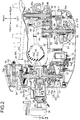
- FIG. 1 schematically shows a scooter type two-wheeled motor vehicle related to one embodiment of a saddle-ridden vehicle.
- the two-wheeled motor vehicle 11 includes a body frame 12 and a body cover 13.
- the body frame 12 includes a head pipe 14 at the front end, a main frame 15 joined to the head pipe 14 via its front end, a cross pipe 16 joined to a rear part of the main frame 15 and extending in the vehicle width direction, and a pair of left and right rear frames 17 having front end parts connected to opposite end parts of the cross pipe 16 and extending in the vehicle fore-and-aft direction.
- a front fork 18 supporting a front wheel WF so that it can rotate around a horizontal axis and rod-shaped handlebars 19 are steerably supported on the head pipe 14.
- the body cover 13 is fitted onto the body frame 12.
- a rider's seat 21 is mounted on the body cover 13 above the rear frame 17.
- the body cover 13 includes a front cover 22 that covers the head pipe 14 from the front, a leg shield 23 that is continuous from the front cover 22, and a step floor 24 that is continuous from the lower end of the leg shield 23 and is disposed above the main frame 15 between the rider's seat 21 and the front wheel WF.
- a unit-swing type drive unit 25 is disposed in a space beneath the rear frame 17.
- the drive unit 25 is vertically swingably linked, via a link 27, to a bracket 26 joined to the front end of the rear frame 17.
- a rear wheel WR is supported by the rear end of the drive unit 25 so that it can rotate around a horizontal axis.
- a rear cushion unit 28 is disposed between the rear frame 17 and the drive unit 25 at a position spaced from the link 27 and the bracket 26.
- the drive unit 25 includes an air-cooled single-cylinder internal combustion engine 29 and a transmission device 31 that is connected to the internal combustion engine 29 and the rear wheel WR and transmits output from the internal combustion engine 29 to the rear wheel WR.
- a transmission case 31a of the transmission device 31 is joined to an engine main body 29a of the internal combustion engine 29.
- the engine main body 29a of the internal combustion engine 29 includes a crankcase 33 that supports a crankshaft 32 so that it can rotate around a rotational axis, a cylinder block 34 that is joined to the crankcase 33, a cylinder head 35 that is joined to the cylinder block 34, and a head cover 36 that is joined to the cylinder head 35.
- An intake device 37 and an exhaust device 38 are connected to the cylinder head 35.
- the intake device 37 includes an air cleaner 39 that is supported on the transmission case 31a and a throttle body 41 that is disposed between the air cleaner 39 and the cylinder head 35.
- a fuel injection valve 42 is mounted on an upper side wall of the cylinder head 35.
- the exhaust device 38 includes an exhaust pipe 43 that extends rearward from a lower side wall of the cylinder head 35 while passing beneath the engine main body 29a, and an exhaust muffler (not illustrated) that is connected to the downstream end of the exhaust pipe 43 and is linked to the crankcase 33.
- a cylinder bore 44 is defined in the cylinder block 34.
- a piston 45 is slidably fitted into the cylinder bore 44 along a cylinder axis C.
- the cylinder axis C is inclined slightly upward to the front.
- the crankshaft 32 is linked to the piston 45.
- a rotational axis X is of the crankshaft 32 is oriented in the vehicle width direction.
- a combustion chamber 46 is defined in the cylinder head 35.
- the combustion chamber 46 is continuous from the cylinder bore 44.
- the piston 45 faces the cylinder head 35 and defines the combustion chamber 46 between itself and the cylinder head 35.
- An air-fuel mixture is introduced into the combustion chamber 46 via the intake device 37.
- Exhaust gas within the combustion chamber 46 is discharged via the exhaust device 38.
- the crankcase 33 is divided into a first case half 33a and a second case half 33b.
- the first case half 33a and the second case half 33b define in cooperation a crank chamber 47.
- a crank of the crankshaft 32 is housed in the crank chamber 47.
- the first case half 33a has a bearing 48a that rotatably supports the crankshaft 32 whereas the second case half 33b has a bearing 48b that rotatably supports the crankshaft 32.
- the AC generator starter 49 is joined to the crankcase 33.
- the AC generator starter 49 includes an outer rotor 51 that is fixed to the crankshaft 32, which extends through the first case half 33a of the crankcase 33 and protrudes out of the first case half 33a, and an inner stator 52 that is surrounded by the outer rotor 51 and is disposed around the crankshaft 32.
- the inner stator 52 is fixed to a support plate 53 fastened to the first case half 33a.
- An electromagnetic coil 52a is wound around the inner stator 52.
- a magnet 51a is fixed to the outer rotor 51. When the outer rotor 51 rotates relative to the inner stator 52, electric power is generated in the electromagnetic coil 52a.
- the AC generator starter 49 functions as a motor.
- the AC generator starter 49 can rotate the crankshaft 32 without employing a gear, etc.
- a control circuit (ECU) is connected to the AC generator starter 49.
- the control circuit controls the supply of electric power to the electromagnetic coil 52a.
- the driving force of the AC generator starter 49 may be used for example for rotating the crankshaft 32 as a starter when starting the internal combustion engine 29 or may be used when smoothly re-starting the two-wheeled motor vehicle 11 when idle stop is performed.
- the control circuit has for example an idle stop determination part, an idle stop control part, and a motor idle drive processing part.
- the idle stop determination part has a function of determining whether or not idle stop control is carried out when the vehicle temporarily stops during travel. Inputted into the idle stop determination part are a throttle degree of opening calculated by a throttle degree of opening calculation part and a travel speed of the vehicle calculated by a vehicle speed calculation part. When the throttle degree of opening and the travel speed attain a predetermined value or below, the idle stop determination part outputs a command signal for idle stop control to the idle stop control part. A command signal is supplied from an idle stop SW determination part to the idle stop determination part. If it is confirmed by the command signal that an idle stop switch is ON, then the idle stop determination part prompts the execution of idle stop control.
- the idle stop control part carries out idle stop control based on the command signal of the idle stop determination part.
- the idle stop control part stops operation of the fuel injection valve 42 and operation of a spark plug. Combustion of the internal combustion engine 29 is thereby suspended.
- the idle stop control part carries out control so that, based on the rotational angle of the crankshaft 32, the crankshaft 32 is driven in reverse and ensures that the crankshaft 32 is driven normally.
- the motor idle drive processing part carries out motor idle control in which the engine rotational speed is maintained at a predetermined rotational speed while the two-wheeled motor vehicle 11 is stopped in a state in which combustion of the internal combustion engine 29 is stopped by the idle stop determination part and the idle stop control part.
- the motor idle drive processing part stops motor idle control when an accelerator demand is not detected after a predetermined time has elapsed. If an accelerator demand is detected before a predetermined time has elapsed, the crankshaft 32 is rotated by the AC generator starter 49, and the two-wheeled motor vehicle 11 is started. At the same time as starting the two-wheeled motor vehicle 11 the combustion stroke of the internal combustion engine 29 is resumed.
- a tubular generator cover 54 surrounding the AC generator starter 49 is joined to the first case half 33a.
- An air inlet 54a is defined at an open end of the generator cover 54.
- a radiator 55 is disposed in the air inlet 54a.
- a cooling fan 56 is joined to an outer face of the outer rotor 51. The cooling fan 56 rotates in response to rotation of the crankshaft 32, and cooling air flows toward the radiator 55.
- the transmission device 31 includes an electronically controlled V-belt-type continuously variable transmission (hereinafter called a 'transmission') 57 that is housed within the transmission case 31a and steplessly changes the speed of rotational power transmitted from the crankshaft 32, and a reduction gear mechanism 59 that is housed within the transmission case 31a, reduces the speed of rotational power of the transmission 57, and transmits it to an axle 58 of the rear wheel WR.
- the rear wheel WR is disposed between the transmission case 31a and a support arm 61.
- the support arm 61 is continuous from the crankcase 33 and extends to the rear of the vehicle.
- the exhaust muffler described above is mounted on the support arm 61.
- the axle 58 of the rear wheel WR is doubly supported, on the transmission case 31a and on the support arm 61, so that it can rotate around its axis.
- the transmission case 31a includes a case main body 62 that is continuous from the second case half 33b of the crankcase 33, a case cover 64 that is fastened to the case main body 62 and defines a transmission chamber 63 between itself and the case main body 62, and a gear cover 66 that is fastened to the case main body 62 and defines a gear chamber 65 between itself and the case main body 62.
- the transmission 57 is housed in the transmission chamber 63.
- the reduction gear mechanism 59 is housed in the gear chamber 65.
- the case main body 62 and the case cover 64 in cooperation form a transmission case.
- the transmission 57 includes a drive pulley device 67 that is disposed within the transmission chamber 63 and is mounted on the crankshaft 32 as a drive shaft, and a driven pulley device 69 that is disposed within the transmission chamber 63 and is mounted on a driven shaft 68 protruding from the transmission chamber 63 into the gear chamber 65.
- a V-belt 71 is wound around a fixed sheave 73 that is fixed to the crankshaft 32 and a movable sheave 74 that is supported on the crankshaft 32 so that it can move in the axial direction of the crankshaft 32 while facing the fixed sheave 73.
- the V-belt 71 is wound around a fixed sheave 78 that is coaxially fitted around the driven shaft 68 and a movable sheave 79 that is coaxially fitted around the driven shaft 68 while facing the fixed sheave 78.
- the belt winding diameter is electronically controlled so as to be variable by the operation of an actuator unit 72.
- the belt winding diameter of the driven pulley device 69 changes in response to a change in the belt winding diameter of the drive pulley device 67.
- the movable sheave 74 is disposed between the second case half 33b of the crankcase 33 and the fixed sheave 73.
- the movable sheave 74 has a movable sheave boss 74a that receives the crankshaft 32.
- the movable sheave boss 74a extends from a sheave body that receives the V belt 71 toward the second case half 33b of the crankcase 24.
- the transmission 57 includes a first shift mechanism 75a, which includes a centrifugal weight and a cam plate, and a second shift mechanism 75b, which includes the actuator unit 72. Axial movement of the movable sheave 74 is realized in response to operation of the first shift mechanism 75a and the second shift mechanism 75b, and the winding radius of the V-belt 71 is changed.
- the driven pulley device 69 includes an inner tube 76 that has a cylindrical shape coaxial with the driven shaft 68 and is coaxially fitted around the driven shaft 68, and an outer tube 77 that has a cylindrical shape coaxial with the driven shaft 68 and is coaxially fitted around the inner tube 76.
- the inner tube 76 is relatively rotatably supported on the driven shaft 68.
- the outer tube 77 is relatively rotatably and axially relatively displaceably supported on the inner tube 76.
- the fixed sheave 78 is coaxially fixed to the inner tube 76.
- the inner tube 76 and the fixed sheave 78 are formed as a unit from a material that is lighter than steel, such as for example aluminum.
- the movable sheave 79 is coaxially fixed to the outer tube 77.
- the outer tube 77 and the movable sheave 79 are formed as a unit from a material that is lighter than steel, such as for example aluminum.
- the movable sheave 79 moves closer to the fixed sheave 78 or moves away from the fixed sheave 78 according to relative displacement in the axial direction between the outer tube 77 and the inner tube 76.
- a centrifugal clutch 81 is fitted around the driven shaft 68.
- the centrifugal clutch 81 includes a clutch plate 81a that is fixed to the inner tube 76.
- a coil spring 82 is disposed between the clutch plate 81a and the movable sheave 79.
- the coil spring 82 exhibits a resilient force that pushes the movable sheave 79 toward the fixed sheave 78.
- the centrifugal clutch 81 includes an outer plate 81b that is fixed to the driven shaft 68.
- the outer plate 81b faces the clutch plate 81a.
- the clutch plate 81a rotates
- the outer plate 81b is joined to the clutch plate 81a by the action of centrifugal force. Rotation of the driven pulley device 69 is thus transmitted to the driven shaft 68.
- the centrifugal clutch 81 establishes a power transmission state.
- the reduction gear mechanism 59 includes a drive gear 83 fixed to the driven shaft 68 protruding into the gear chamber 65, a final gear 84 fixed to the axle 58 of the rear wheel WR, and idle gears 85a and 85b disposed between the drive gear 83 and the final gear 84.
- the idle gears 85a and 85b are fixed to a common intermediate shaft 86.
- the drive gear 83 meshes with the idle gear 85a
- the final gear 84 meshes with the idle gear 85b. In this way, rotation of the driven shaft 68 is reduced in speed and transmitted to the axle 58 of the rear wheel WR.
- the internal combustion engine 29 has a valve operating mechanism 87.
- the valve operating mechanism 87 includes an intake valve 88 that has a valve body 88a disposed within the combustion chamber 46 and is supported on the cylinder head 35 so that it can be displaced in the axial direction via a valve shaft 88b extending from the valve body 88a, and an exhaust valve 89 that has a valve body 89a disposed within the combustion chamber 46 and is supported on the cylinder head 35 so that it can be displaced in the axial direction via a valve shaft 89b extending from the valve body 89a.
- valve body 88a of the intake valve 88 is seated on a valve seat 92a that is embedded in the cylinder head 35 at the opening of an intake port 91a communicating with the combustion chamber 46 and defines an intake aperture.
- valve body 89a of the exhaust valve 89 is seated on a valve seat 92b that is embedded in the cylinder head 35 at the opening of an exhaust port 91b communicating with the combustion chamber 46 and defines an exhaust aperture.
- the valve shafts 88b and 89b are axially slidably supported on the cylinder head 35.
- the valve shafts 88b and 89b extend through the cylinder head 35 and have one end (outer end) disposed outside the combustion chamber 46.
- a flange 93 is fixed to the outer ends of the valve shafts 88b and 89b.
- a coil spring 94 which is an elastic member, is sandwiched between the flange 93 and an outer face of the cylinder head 35.
- the coil spring 94 exerts a resilient force in an expansion direction in which the flange 93 moves away from the outer face of the cylinder head 35.
- the valve bodies 88a and 89a are seated on the valve seats 92a and 92b based on the resilient force of the coil spring 94.
- the valve operating mechanism 87 includes a cam shaft 95 that is supported on the cylinder head 35 so that it can rotate around an axis Xc parallel to the rotational axis Xis of the crankshaft 32, a pair of rocker shafts 96 that have an axis Xk parallel to the rotational axis Xis of the crankshaft 32 and are supported on the cylinder head 35, and an intake side rocker arm 97a and an exhaust side rocker arm 97b that are supported on the rocker shaft 96 so that they can swing around the axis Xk.
- the individual rocker arms 97a and 97b include a first arm 99 that extends from the rocker shaft 96 in the centrifugal direction and has an action point 98 at the extremity, and a second arm 102 that extends from the rocker shaft 96 toward the side opposite to the first arm 99 in the centrifugal direction and has a cam follower 101 at the extremity.
- the rocker arms 97a and 97b make contact with the outer end of the intake valve 88 and the exhaust valve 89 respectively via the action point 98 of the first arm 99.
- the rocker arms 97a and 97b respectively make contact with the cam shaft 95 via the cam follower 101. Details of the cam shaft 95 and the rocker arms 97a and 97b are described later.
- the valve operating mechanism 87 includes a timing chain 103.
- the timing chain 103 is wound around a crank sprocket (not illustrated) fixed to the crankshaft 32 and a cam sprocket 104 fixed to the cam shaft 95.
- the timing chain 103 transmits rotation of the crankshaft 32 to the cam shaft 95.
- the cam shaft 95 rotates in synchronism with rotation of the crankshaft 32.
- the internal combustion engine 29 includes a spark plug 105.
- the spark plug 105 is supported on the cylinder head 35.
- the spark plug 105 extends through the cylinder head 35 and has an electrode 105 a at the extremity extending to the interior of the combustion chamber 46.
- the spark plug 105 ignites the air-fuel mixture within the combustion chamber 46 with a spark generated on the electrode 105a in response to a supplied electric signal.
- the cam shaft 95 is rotatably supported on the cylinder head 35 via a pair of bearings 106.
- the bearing 106 employs for example a ball bearing.
- a first cam 107 for the intake side rocker arm 97a and a second cam 108 for the exhaust side rocker arm 97b are formed on the cam shaft 95 between the bearings 106.
- the first cam 107 and the second cam 108 are disposed so as to be displaced in the axial direction of the cam shaft 95.
- the cam follower 101 includes a roller 109 that is supported on the second arm 102 so that it can rotate around a rotational axis parallel to the axis Xc of the cam shaft 95.
- An outer peripheral face of the roller 109 makes contact with the first cam 107 and the second cam 108 respectively.
- the rollers 109 receive rotation of the first cam 107 and the second cam 108 and can rotate.
- the roller 109 follows the profile of the first cam 107 and the second cam 108 while rotating. Moving the rollers 109 closer to or away from the axis Xc of the cam shaft 95 controls the opening and closing of the intake valve 88 and the exhaust valve 89.
- the first cam 107 includes a base face 107a that has a partial cylindrical face shape that is coaxial with the axis Xc of the cam shaft 95, and a lift face 107b that is provided on the cam shaft 95 so as to be continuous from the base face 107a in the rotational direction and bulges further outward in the radial direction than the base face 107a so as to define an amount of lift of the intake valve 88.
- the cam follower 101 of the intake side rocker arm 97a maintains contact with the base face 107a and the lift face 107b and causes the intake side rocker arm 97a to swing.
- the second cam 108 includes a base face 108a that has a partial cylindrical face shape that is coaxial with the axis Xc of the cam shaft 95, and a lift face 108b that is provided on the cam shaft 95 so as to be continuous from the base face 108a in the rotational direction and bulges further outward in the radial direction than the base face 108a so as to define a lift amount of the exhaust valve 89.
- the cam follower 101 of the exhaust side rocker arm 97b maintains contact with the base face 108a and the lift face 108b and causes the exhaust side rocker arm 97b to swing.
- the valve operating mechanism 97 includes a decompression device 111 related to the first embodiment.
- the decompression device 111 includes a decompression cam 112 that is attached to the cam shaft 95, a decompression follower 113 that is defined on the exhaust side rocker arm 97b so that it can make contact with the decompression cam 112, and a drive arm 114 that is attached to the cam shaft 95 and drives the decompression cam 112 between an operating position and a non-operating position.
- the decompression cam 112 and the drive arm 114 are supported on a step face 115 formed on the cam shaft 95 between the second cam 108 and the bearing 106.
- the step face 115 is defined between a large diameter shaft 116a that defines the second cam 108 and a small diameter shaft 116b that is continuous from the large diameter shaft 116a, has a smaller diameter than that of the large diameter shaft 116a, and is received by the bearing 106, and is made to face the bearing 106.
- the step face 115 is orthogonal to the axis Xc of the cam shaft 95 and is connected to edges of the base face 108a and the lift face 108b of the second cam 108.
- the decompression cam 112 includes a shaft body 117 that has an axis parallel to the axis Xc of the cam shaft 95.
- the decompression cam 112 is supported on the cam shaft 95 so that it can rotate around the rotational axis Xd.
- the decompression cam 112 includes a cam main body 119 that is coaxial with the shaft body 117.
- a cylindrical face 121 is defined on the cam main body 119, the cylindrical face 121 being coaxial with the shaft body 117 and continuous around the axis of the shaft body 117.
- the cylindrical face 121 is disposed at a position displaced, in the axial direction of the cam shaft 95, from an imaginary cylindrical face 122 that is drawn coaxially with the axis Xc of the cam shaft 95 and faces the decompression follower 113.
- the imaginary cylindrical face 122 is a cylindrical face that is coaxial with the cylindrical face 121 and continuous from the cylindrical face 121 in the axial direction.
- the decompression cam 112 has a cam groove 124 that receives a cam pin 123.
- the cam pin 123 is formed from a columnar body that has an axis parallel to the axis Xc of the cam shaft 95.
- the cam groove 124 is formed in an end face of the cam main body 119 and extends linearly from the cylindrical face 121 toward the axis.
- the drive arm 114 is supported on the cam shaft 95 so that it can swing around a swing shaft 125.
- the swing shaft 125 has an axis parallel to the axis Xc of the cam shaft 95.
- the swing shaft 125 is pushed into the step face 115 by for example press fitting.
- a spacer 126 is fitted around the swing shaft 125 between the step face 115 and the drive arm 114.
- the dimension of the spacer 126 in the axial direction of the cam shaft 95 corresponds to the dimension of the imaginary cylindrical face 122.
- the imaginary cylindrical face 122 is thus disposed between the drive arm 114 and the step face 115.
- the swing shaft 125 is disposed at a position spaced from the rotational axis Xd of the decompression cam 112 at least in the peripheral direction of the cam shaft 95.
- the swing shaft 125 is desirably separated from the decompression cam 112 as far as possible.
- the swing shaft 125 and the rotational axis Xd of the decompression cam 112 are disposed on one diameter on opposite sides of the axis Xc.
- the cam pin 123 is fixed to the extremity of the drive arm 114.
- the cam pin 123 moves between a first position where the operating position of the decompression cam 112 is established and a second position where the non-operating position of the decompression cam 112 is established.
- a torsion spring 127 is fitted onto the spacer 126. One end of the torsion spring 127 is latched to the drive arm 114. The other end of the torsion spring 127 is latched to the small diameter shaft 116b.
- the torsion spring 127 exerts a resilient force driving the cam pin 123 toward the first position.
- the drive arm 114 curves so as to bypass the small diameter shaft 116b between the swing shaft 125 and the cam pin 123.
- a centrifugal weight 128 is mounted on the drive arm 114 between the swing shaft 125 and the cam pin 123. When the rotation of the cam shaft 95 attains a preset rotational speed, the centrifugal weight 128 exerts a centrifugal force that moves the cam pin 123 from the first position to the second position against the resilient force of the torsion spring 127.
- the cam main body 119 of the decompression cam 112 has a partial cylindrical face 129 that is disposed within a space on the inner side of the imaginary cylindrical face 122 and is continuous from the cylindrical face 121 coaxially with the shaft body 117, and a flat face 131 that connects generatrices of opposite ends of the partial cylindrical face 129 to each other.
- the decompression cam 112 has part of the partial cylindrical face 129 projecting to the outside from the imaginary cylindrical face 122 in the operating position.
- the partial cylindrical face 129 corresponds to a curved protruding face having a generatrix parallel to the axis Xc of the cam shaft 95.
- the decompression follower 113 includes a convexly curved convex decompression follower face 133 that is provided on the exhaust side rocker arm 97b on the outer side of the imaginary cylindrical face 122, opposes the imaginary cylindrical face 122 at a position closest to the imaginary cylindrical face 122, and makes contact with the partial cylindrical face 129, a first concave decompression follower face 134 that is provided on the upstream of the convex decompression follower face 133 in the normal rotational direction of the cam shaft 95, is formed as a concavely curved face having a generatrix parallel to the axis Xc of the cam shaft 95, and makes contact with the partial cylindrical face 129, and a second concave decompression follower face 135 that is provided on the downstream of the convex decompression follower face 133 in the normal rotational direction of the cam shaft 95, is formed as a concavely curved face having a generatrix parallel to the axis
- a first auxiliary concave decompression follower face 136 formed as a concavely curved face having a smaller curvature than that of the partial cylindrical face 129.
- a second auxiliary concave decompression follower face 137 formed as a concavely curved face having a smaller curvature than that of the partial cylindrical face 129 is formed between the convex decompression follower face 133 and the second concave decompression follower face 135.
- An upstream end 134a of the first concave decompression follower face 134 is disposed at a position further away from the axis Xc of the cam shaft 95 in the radial direction than the partial cylindrical face 129.
- a downstream end 135a of the second concave decompression follower face 135 is disposed at a position further away from the axis Xc of the cam shaft 95 in the radial direction than the partial cylindrical face 129.
- the first concave decompression follower face 134 moves away from the axis Xc of the cam shaft 95 in going away from the convex decompression follower face 133 in the peripheral direction of the imaginary cylindrical face 122.
- the second concave decompression follower face 135 moves away from the axis Xc of the cam shaft 95 in going away from the convex decompression follower face 133 in the peripheral direction of the imaginary cylindrical face 122.
- the first concave decompression follower face 134 is formed from part of a cylindrical face having a smaller curvature than that of the partial cylindrical face 129.
- the second concave decompression follower face 135 is formed from part of a cylindrical face having a smaller curvature than that of the partial cylindrical face 129.
- the first auxiliary concave decompression follower face 136 is formed from part of a cylindrical face having a smaller curvature than that of the partial cylindrical face 129.
- the second auxiliary concave decompression follower face 137 is formed from part of a cylindrical face having a smaller curvature than that of the partial cylindrical face 129.
- the first auxiliary concave decompression follower face 136 is formed from part of a cylindrical face having a larger curvature than that of the first concave decompression follower face 134.
- the second auxiliary concave decompression follower face 137 is formed from part of a cylindrical face having a larger curvature than that of the second concave decompression follower face 135.
- the first auxiliary concave decompression follower face 136 and the second auxiliary concave decompression follower face 137 may be formed from part of a cylindrical face having a smaller curvature than that of the convex decompression follower face 133 or may be formed from part of a cylindrical face having a larger curvature than that of the convex decompression follower face 133.
- the convex decompression follower face 133 moves further away from the axis Xc of the cam shaft 95 than the outer peripheral face of the roller 109. Since the cylindrical face 121 and the imaginary cylindrical face 122 have the same diameter, a constant gap is maintained between the convex decompression follower face 133 and the imaginary cylindrical face 122. As shown in FIG. 7 , when the decompression cam 112 is at the non-operating position, if the flat face 131, which is continuous from the partial cylindrical face 129, is disposed on the inner side of the imaginary cylindrical face 122, contact between the decompression cam 112 and the decompression follower 113 is avoided.
- the intake stroke, the compression stroke, the combustion stroke, and the exhaust stroke are repeated in sequence.
- the intake stroke the intake stroke.
- the piston 45 descends due to the inertial force of the crankshaft 32.
- the air-fuel mixture is introduced into the combustion chamber 46.
- Fuel is injected into air introduced from the air intake device 37 from the fuel injection valve 42 in the throttle body 41.
- the compression stroke the piston 45 ascends due to the inertial force of the crankshaft 32.
- the intake valve 88 and the exhaust valve 89 are maintained in a closed state.
- the air-fuel mixture is compressed within the combustion chamber 46.
- the air-fuel mixture is ignited within the combustion chamber 46.
- the intake valve 88 and the exhaust valve 89 are maintained in a closed state.
- the piston 45 descends due to the action of the explosion within the combustion chamber 46.
- the driving force is transmitted to the crankshaft 32.
- the exhaust stroke the exhaust valve 89 is opened.
- the piston 45 ascends due to the inertial force of the crankshaft 32.
- Exhaust gas after combustion escapes into the exhaust pipe 43.
- the intake stroke is carried out again.
- a driving force is transmitted to the crankshaft 32 from the AC generator starter 49.
- the AC generator starter 49 generates a driving force for example in response to electric power supplied from a battery (not illustrated).
- the valve operating mechanism 87 operates in association with rotation of the crankshaft 32. Opening and closing of the intake valve 88 is controlled by swinging of the intake side rocker arm 97a. The rocker arm 97a swings in response to contact between the roller 109 and the first cam 107. While the roller 109 is in contact with the base face 107a of the first cam 107, the rocker arm 97a maintains a valve-closed state of the intake valve 88. When the roller 109 follows the lift face 107b, the intake valve 88 opens. Opening and closing of the exhaust valve 89 is controlled by swinging of the exhaust side rocker arm 97b. The rocker arm 97b swings in response to contact between the roller 109 and the second cam 108.
- the drive arm 114 therefore maintains the cam pin 123 at the first position in response to the resilient force of the torsion spring 127.
- the decompression cam 112 is positioned at the operating position.
- the partial cylindrical face 129 projects from an imaginary cylindrical face, including the imaginary cylindrical face 122.
- the partial cylindrical face 129 makes contact with the first concave decompression follower face 134, the first auxiliary concave decompression follower face 136, the convex decompression follower face 133, the second auxiliary concave decompression follower face 137, and the second concave decompression follower face 135 of the decompression follower 113 one after another.
- the exhaust valve 89 is opened during the compression stroke.
- the pressure within the combustion chamber 46 is released.
- the drive resistance of the piston 45 is alleviated, and vibration of the internal combustion engine is suppressed.
- the decompression device 111 When the engine rotational speed of the internal combustion engine 29 attains a predetermined rotational speed or greater, in the decompression device 111 a sufficient centrifugal force is generated by the centrifugal weight 128 in response to rotation of the cam shaft 95.
- the drive arm 114 therefore drives the cam pin 123 from the first position to the second position against the resilient force of the torsion spring 127.
- the decompression cam 112 changes its attitude to the non-operating position.
- the decompression cam 112 is contained inside the imaginary cylindrical face, including the imaginary cylindrical face 122.
- the partial cylindrical face 129 of the decompression cam 112 projects in the centrifugal direction of the cam shaft 95. While the cam shaft 95 is rotating normally, the partial cylindrical face 129 of the decompression cam 112 makes contact with the first concave decompression follower face 134 and the convex decompression follower face 133 of the exhaust side of the rocker arm 97b one after another. Since the first concave decompression follower face 134 is formed as a concavely curved face, at the start of contact the partial cylindrical face 129 of the decompression cam 112 can slip against the concavely curved face in a tangential direction. Therefore, noise due to collision between the decompression cam 112 and the exhaust side rocker arm 97b can be suppressed.
- the upstream end 134a of the first concave decompression follower face 134 is disposed at a position further away from the axis Xc of the cam shaft 95 than the partial cylindrical face 129 of the rocker arm 97b.
- the partial cylindrical face 129 of the decompression cam 112 reliably makes contact with the concavely curved face of the first concave decompression follower face 134. Noise due to collision between the decompression cam 112 and the exhaust side rocker arm 97b can be suppressed.
- the first concave decompression follower face 134 related to the present embodiment moves away from the axis Xc of the cam shaft 95 in going away from the convex decompression follower face 133. Therefore, even if the position of the partial cylindrical face 129 of the decompression cam 112 is somehow displaced due to dimensional tolerance or assembly error, when starting contact the partial cylindrical face 129 of the decompression cam 112 can slip against the first concave decompression follower face 134 in a tangential direction. Therefore, noise due to collision between the decompression cam 112 and the exhaust side rocker arm 97b can be suppressed.
- the first auxiliary concave decompression follower face 136 is formed between the convex decompression follower face 133 and the first concave decompression follower face 134, the first auxiliary concave decompression follower face 136 being formed as a concavely curved face having a smaller curvature than that of the partial cylindrical face 129 of the decompression cam 112.
- the partial cylindrical face 129 of the decompression cam 112 can smoothly follow the first concave decompression follower face 134 and then the convex decompression follower face 133. Noise due to collision between the decompression cam 112 and the exhaust side rocker arm 97b can be suppressed.
- the first auxiliary concave decompression follower face 136 is formed from part of a cylindrical face having a larger curvature than that of the first concave decompression follower face 134.
- the partial cylindrical face 129 of the decompression cam 112 makes contact with the convex decompression follower face 133 and the second concave decompression follower face 135 in succession. Since the second concave decompression follower face 135 is formed as a concavely curved face, when the decompression cam 112 disengages from the second concave decompression follower face 135, the amount of lift of the exhaust valve 89 changes gently. As a result, the noise of seating of the exhaust valve 89 (seating noise) is reduced.
- the partial cylindrical face 129 of the decompression cam 112 makes contact with the second concave decompression follower face 135 and the convex decompression follower face 133 one after another. Since the second concave decompression follower face 135 is formed as a concavely curved face, when starting contact the partial cylindrical face 129 of the decompression cam 112 can slip against the concavely curved face in a tangential direction. Therefore, when the piston 45 cannot completely ride over compression top dead center and the cam shaft 95 rotates in reverse, noise due to collision between the decompression cam 112 and the exhaust side rocker arm 97b can be suppressed.
- the downstream end 135a of the second concave decompression follower face 135 is disposed at a position further away from the axis Xc of the cam shaft 95 than the partial cylindrical face 129 of the decompression cam 112.
- the partial cylindrical face 129 of the decompression cam 112 moves away from the rocker arm 97b via the concavely curved face in response to rotation of the cam shaft 95.
- the second concave decompression follower face 135 related to the present embodiment moves away from the axis Xc of the cam shaft 95 in going away from the convex decompression follower face 133. Therefore, even if the position of the partial cylindrical face 129 of the decompression cam 112 is somehow displaced due to dimensional tolerance or assembly error, when being seated the amount of lift of the exhaust valve 89 changes gently. In this way the noise of seating of the exhaust valve 89 can be reduced.
- the second auxiliary concave decompression follower face 137 formed as a concavely curved face having a smaller curvature than that of the partial cylindrical face 129 of the decompression cam 112 is formed between the convex decompression follower face 133 and the second concave decompression follower face 135. Since the convex decompression follower face 133, the second auxiliary concave decompression follower face 137, and the second concave decompression follower face 135 are continuous, the partial cylindrical face 129 of the decompression cam 112 can smoothly follow the convex decompression follower face 133 and then the second concave decompression follower face 135. Noise due to collision between the decompression cam 112 and the exhaust side rocker arm 97b can be suppressed.
- the second auxiliary concave decompression follower face 137 is formed from part of a cylindrical face having a larger curvature than that of the second concave decompression follower face 135.
- the partial cylindrical face 129 of the decompression cam 112 can smoothly follow the convex decompression follower face 133 and then the second concave decompression follower face 135 in response to a change in the curvature. Noise due to collision between the decompression cam 112 and the exhaust side rocker arm 97b can be suppressed.
- the internal combustion engine 29 employs motor idling control.
- motor idling control fuel is not injected from the fuel injection valve 42 into air introduced from the air intake device 37 into the combustion chamber 46 when the accelerator is OFF (a state in which the accelerator is not operated).
- a driving force is transmitted from the AC generator starter 49 to the crankshaft 32.
- the AC generator starter 49 generates a driving force in response to electric power supplied from for example a battery (not illustrated).
- the AC generator starter 49 can make the piston 45 move back and forth without going through the combustion stroke. Fuel consumption is suppressed and the exhaust noise of the internal combustion engine 29 is reduced.
- FIG. 8 schematically shows the arrangement of a decompression device 141 related to a second embodiment.
- a decompression follower 142 has a convex decompression follower face 143 that is a single convexly curved face instead of the first concave decompression follower face 134, the first auxiliary concave decompression follower face 136, the convex decompression follower face 133, the second auxiliary concave decompression follower face 137, and the second concave decompression follower face 135 described above.
- a curved protruding face 145 of a decompression cam 144 has a peak face 146 that project furthest from the imaginary cylindrical face 122, a first buffer face 147 that is provided on the upstream of the peak face 146 in the normal rotational direction of the cam shaft 95 and is formed as a concavely curved face having a generatrix parallel to the axis Xc of the cam shaft 95, and a second buffer face 148 that is provided on the downstream of the peak face 146 in the normal rotational direction of the cam shaft 95 and is formed as a concavely curved face having a generatrix parallel to the axis Xc of the cam shaft 95.
- the arrangement is otherwise the same as that of the preceding embodiment.
- the convex decompression follower face 143 of the decompression follower 142 is formed from part of a cylindrical face that is coaxial with the rotational axis of the roller 109 and has a smaller diameter than that of the roller 109. Therefore, the convex decompression follower face 143 is made to face the imaginary cylindrical face 122 across a set gap.
- the peak face 146 of the decompression cam 144 is formed from part of a cylindrical face having the same diameter as that of the partial cylindrical face 129.
- the first buffer face 147 and the second buffer face 148 of the decompression cam 144 are each formed as a partial cylindrical face having a smaller curvature than that of the convex decompression follower face 143.
- An upstream end 147a of the first buffer face 147 is disposed at a position closer to the axis Xc of the cam shaft 95 than the convex decompression follower face 143 when the decompression cam 144 is positioned at an operating position.
- a downstream end 148a of the second buffer face 148 is disposed at a position closer to the axis Xc of the cam shaft 95 than the convex decompression follower face 143 when the decompression cam 144 is positioned at an operating position.
- the curved protruding face 145 of the decompression cam 144 makes contact with the convex decompression follower face 143 of the exhaust side rocker arm 97b via the first buffer face 147 and the peak face 146 one after another. Since the first buffer face 147 of the decompression cam 144 is formed as a concavely curved face, when starting contact the convex decompression follower face 143 can slip against the first buffer face 147 of the decompression cam 144 in a tangential direction. Therefore, noise due to collision between the decompression cam 114 and the exhaust side rocker arm 97b can be suppressed.
- the curved protruding face 145 of the decompression cam 144 makes contact with the convex decompression follower face 143 via the peak face 146 and then via the second buffer face 148. Since the second buffer face 148 is formed as a concavely curved face, when the convex decompression follower face 143 disengages from the second buffer face 148, the amount of lift of the exhaust valve 89 changes gently. As a result, the noise of seating of the exhaust valve 89 (seating noise) is reduced. Moreover, while the cam shaft 95 is rotating in reverse, the curved protruding face 145 of the decompression cam 144 makes contact with the second buffer face 148 and the peak face 146 one after another.
- the second buffer face 148 is formed as a concavely curved face, when starting contact the convex decompression follower face 143 can slip against the second buffer face 148 in a tangential direction. Therefore, when the piston 45 cannot completely ride over compression top dead center and the cam shaft 95 rotates in reverse, noise due to collision between the decompression cam 114 and the exhaust side rocker arm 97b can be suppressed.
- FIG. 9 schematically shows the arrangement of a decompression device 151 related to a third embodiment.
- the cam follower 101 also functions as the decompression follower 142. That is, the roller 109 of the cam follower 101 functions, over the entire periphery of the cylindrical face, as the convex decompression follower face 143 having the convexly curved face described above.
- the roller 109 is made to face the imaginary cylindrical face 122 across a set gap.
- the peak face 146 of the decompression cam 144 is formed as part of a cylindrical face having the same diameter as that of the partial cylindrical face 129.
- the first buffer face 147 and the second buffer face 148 of the decompression cam 144 are each formed as a partial cylindrical face having a smaller curvature than that of the cylindrical face of the roller 109.
- the upstream end 147a of the first buffer face 147 is disposed at a position closer to the axis Xc of the cam shaft 95 than the roller 109 when the decompression cam 144 is positioned at the operating position.
- the downstream end 148a of the second buffer face 148 is disposed at a position closer to the axis Xc of the cam shaft 95 than the roller 109 when the decompression cam 144 is positioned at the operating position.
- the arrangement is otherwise the same as that of the second embodiment described above.
- the curved protruding face 145 of the decompression cam 144 makes contact with the roller 109 of the exhaust side rocker arm 97b via the first buffer face 147 and the peak face 146 one after another. Since the first buffer face 147 of the decompression cam 144 is formed as a concavely curved face, when starting contact the roller 109 can slip against the first buffer face 147 of the decompression cam 144 in a tangential direction. Therefore, noise due to collision between the decompression cam 144 and the exhaust side rocker arm 97b can be suppressed.
- the curved protruding face 145 of the decompression cam 144 makes contact with the roller 109 via the peak face 146 and then via the second buffer face 148. Since the second buffer face 148 is formed as a concavely curved face, when the roller 109 disengages from the second buffer face 148, the amount of lift of the exhaust valve 89 changes gently. As a result, the noise of seating of the exhaust valve 89 (seating noise) is reduced. Moreover, while the cam shaft 95 is rotating in reverse, the curved protruding face 145 of the decompression cam 144 makes contact with the second buffer face 148 and the peak face 146 one after another.
- the second buffer face 148 is formed as a concavely curved face, when starting contact the roller 109 can slip against the second buffer face 148 in a tangential direction. Therefore, when the piston 45 cannot completely ride over compression top dead center and the cam shaft 95 rotates in reverse, noise due to collision between the decompression cam 144 and the exhaust side rocker arm 97b can be suppressed.
Landscapes
- Engineering & Computer Science (AREA)
- Mechanical Engineering (AREA)
- General Engineering & Computer Science (AREA)
- Valve Device For Special Equipments (AREA)
Abstract
Description
- The present invention relates to a decompression device of an internal combustion engine.
- Patent Document 1 discloses a decompression device of an internal combustion engine. The decompression device includes a decompression cam having a partial cylindrical face with a small diameter having an axis parallel to the rotational axis of a cam shaft. The decompression cam has part of the partial cylindrical face projecting further than an imaginary cylindrical face coaxial with the cam shaft when the rotational speed is less than a preset value. A slipper of an exhaust side rocker arm makes contact with the projecting decompression cam to thus open an exhaust valve. Due to the exhaust valve opening during a compression stroke in a low rotational speed region, the drive resistance of a piston is reduced, and vibration of the internal combustion engine is suppressed.
- Patent Document 1: Japanese Patent Application Laid-open No.
2014-129794 - When a piston does not completely ride over compression top dead center and a cam shaft rotates in reverse, the noise of a collision between a decompression cam and an exhaust side rocker arm is reduced. There is a requirement not only to reduce such collision noise, but also to reduce the collision noise between the decompression cam and the exhaust side rocker arm when the cam shaft rotates normally and the seating noise of an exhaust valve.
- The present invention has been accomplished in light of the above circumstances, and it is an object thereof to provide an internal combustion engine that can further reduce the collision noise between a decompression cam and an exhaust side rocker arm and the seating noise of an exhaust valve.
- According to a first aspect of the present invention, there is provided an internal combustion engine comprising a base face having a shape with a partial cylindrical face that is coaxial with a rotational axis of a cam shaft, a lift face that is provided on the cam shaft so as to be continuous from the base face in a rotational direction and that bulges further radially outward than the base face to define an amount of lift of an exhaust valve, a cam follower that is provided on an exhaust side rocker arm and causes the exhaust side rocker arm to swing while maintaining contact with the base face and the lift face, a decompression cam that makes a curved protruding face having a generatrix parallel to the rotational axis of the cam shaft project from an imaginary cylindrical face coaxial with the cam shaft when the rotational speed is less than a preset value, a convex decompression follower face with a convexly curved face that is provided on the exhaust side rocker arm on an outer side of the imaginary cylindrical face, that faces the imaginary cylindrical face at a position closest to the imaginary cylindrical face, and that makes contact with the curved protruding face, and a concave decompression follower face that is provided on the upstream of the convex decompression follower face in a normal rotational direction of the cam shaft, that is formed as a concavely curved face having a generatrix parallel to the rotational axis of the cam shaft, and that makes contact with the curved protruding face.
- According to a second aspect of the present invention, in addition to the first aspect, an upstream end of the concave decompression follower face is provided at a position spaced from the rotational axis of the cam shaft compared with the curved protruding face.
- According to a third aspect of the present invention, in addition to the first or second aspect, the concave decompression follower face is positioned remoter from the rotational axis of the cam shaft in going away from the convex decompression follower face.
- According to a fourth aspect of the present invention, in addition to any one of the first to third aspects, the internal combustion engine further comprises an auxiliary concave decompression follower face that is formed between the convex decompression follower face and the concave decompression follower face and that is formed from a concavely curved face having a curvature smaller than a curvature of the curved protruding face.
- According to a fifth aspect of the present invention, in addition to the fourth aspect, the auxiliary concave decompression follower face is formed from part of a cylindrical face having a curvature larger than a curvature of the concave decompression follower face.
- According to a sixth aspect of the present invention, in addition to any one of the first to fifth aspects, the internal combustion engine further comprises a second concave decompression follower face that is provided on the downstream of the convex decompression follower face in the normal rotational direction of the cam shaft, that is formed as a concavely curved face having a generatrix parallel to the rotational axis of the cam shaft, and that makes contact with the curved protruding face.
- According to a seventh aspect of the present invention, there is provided an internal combustion engine comprising a base face having a shape with a partial cylindrical face that is coaxial with a rotational axis of a cam shaft, a lift face that is provided on the cam shaft so as to be continuous from the base face in a rotational direction and that bulges further radially outward than the base face to define an amount of lift of an exhaust valve, a cam follower that is provided on an exhaust side rocker arm and causes the exhaust side rocker arm to swing while maintaining contact with the base face and the lift face, a decompression cam that makes a curved protruding face having a generatrix parallel to the rotational axis of the cam shaft project from an imaginary cylindrical face coaxial with the cam shaft when the rotational speed is less than a preset value, a convex decompression follower face that is provided on the exhaust side rocker arm on an outer side of the imaginary cylindrical face, that faces the imaginary cylindrical face at a position closest to the imaginary cylindrical face, and that makes contact with the curved protruding face, and a concave decompression follower face that is provided on the downstream of the convex decompression follower face in a normal rotational direction of the cam shaft, that is formed as a concavely curved face having a generatrix parallel to the rotational axis of the cam shaft, and that makes contact with the curved protruding face.
- According to an eighth aspect of the present invention, in addition to the seventh aspect, a downstream end of the concave decompression follower face is provided at a position spaced from the rotational axis of the cam shaft compared with the curved protruding face.
- According to a ninth aspect of the present invention, in addition to the seventh or eighth aspect, the concave decompression follower face is positioned remoter from the rotational axis of the cam shaft in going away from the convex decompression follower face.
- According to a tenth aspect of the present invention, in addition to any one of the seventh to ninth aspects, the internal combustion engine further comprises an auxiliary concave decompression follower face that is formed between the convex decompression follower face and the concave decompression follower face and that is formed from a concavely curved face having a curvature smaller than a curvature of the curved protruding face.
- According to an eleventh aspect of the present invention, in addition to the tenth aspect, the auxiliary concave decompression follower face is formed from part of a cylindrical face having a curvature larger than a curvature of the concave decompression follower face.
- According to a twelfth aspect of the present invention, in addition to any one of the first to eleventh aspects, the internal combustion engine further comprises an AC generator that is joined to a crankshaft, that generates electric power in response to rotation of the crankshaft, and that drives the crankshaft around a rotational axis thereof in response to electric power being supplied.
- According to a thirteenth aspect of the present invention, there is provided an internal combustion engine comprising a base face having a shape with a partial cylindrical face that is coaxial with a rotational axis of a cam shaft, a lift face that is provided on the cam shaft so as to be continuous from the base face in a rotational direction and that bulges further radially outward than the base face to define an amount of lift of an exhaust valve, a cam follower that is provided on an exhaust side rocker arm and causes the exhaust side rocker arm to swing while maintaining contact with the base face and the lift face, a decompression cam that makes a curved protruding face having a generatrix parallel to the rotational axis of the cam shaft project from an imaginary cylindrical face coaxial with the cam shaft when the rotational speed is less than a preset value, and a convex decompression follower face with a convexly curved face that is provided on the exhaust side rocker arm on an outer side of the imaginary cylindrical face, that faces the imaginary cylindrical face, and that makes contact with the curved protruding face, the curved protruding face having a peak face that projects the furthest from the imaginary cylindrical face, and a buffer face that is provided on the upstream of the peak face in a normal rotational direction of the cam shaft, that is formed as a concavely curved face having a generatrix parallel to the rotational axis of the cam shaft, and that makes contact with the convex decompression follower face.
- According to a fourteenth aspect of the present invention, in addition to the thirteenth aspect, the curved protruding face further has a second buffer face that is provided on the downstream of the peak face in the normal rotational direction of the cam shaft and that is formed as a concavely curved face having a generatrix parallel to the rotational axis of the cam shaft.
- According to a fifteenth aspect of the present invention, there is provided an internal combustion engine comprising a base face having a shape with a partial cylindrical face that is coaxial with a rotational axis of a cam shaft, a lift face that is provided on the cam shaft so as to be continuous from the base face in a rotational direction and that bulges further radially outward than the base face to define an amount of lift of an exhaust valve, a cam follower that is provided on an exhaust side rocker arm and causes the exhaust side rocker arm to swing while maintaining contact with the base face and the lift face, a decompression cam that makes a curved protruding face having a generatrix parallel to the rotational axis of the cam shaft project from an imaginary cylindrical face coaxial with the cam shaft when the rotational speed is less than a preset value, and a convex decompression follower face with a convexly curved face that is provided on the exhaust side rocker arm on an outer side of the imaginary cylindrical face, that faces the imaginary cylindrical face, and that makes contact with the curved protruding face, the curved protruding face having a peak face that projects the furthest from the imaginary cylindrical face, and a buffer face that is provided on the downstream of the peak face in a normal rotational direction of the cam shaft, that is formed as a concavely curved face having a generatrix parallel to the rotational axis of the cam shaft, and that makes contact with the convex decompression follower face.
- In accordance with the first aspect, in a low rotational speed region in which the rotational speed is less than a set value the curved protruding face of the decompression cam projects in the centrifugal direction of the cam shaft. While the cam shaft is rotating normally, the curved protruding face of the decompression cam makes contact with the concave decompression follower face and the convex decompression follower face of the exhaust side of the rocker arm one after another. Since the concave decompression follower face is formed as a concavely curved face, at the start of contact the curved protruding face of the decompression cam can slip against the concavely curved face in a tangential direction. Therefore, noise due to collision between the decompression cam and the exhaust side rocker arm can be suppressed.
- In accordance with the second aspect, at the start of contact the curved protruding face of the decompression cam makes contact with the concavely curved face. Noise due to collision between the decompression cam and the exhaust side rocker arm can be suppressed.
- In accordance with the third aspect, even if the position of the curved protruding face of the decompression cam is somehow displaced due to dimensional tolerance or assembly error, when starting contact the curved protruding face of the decompression cam can slip against the concavely curved face in a tangential direction. Therefore, noise due to collision between the decompression cam and the exhaust side rocker arm can be suppressed.
- In accordance with the fourth aspect, since the concave decompression follower face, the auxiliary concave decompression follower face, and the convex decompression follower face are continuous, the curved protruding face of the decompression cam can smoothly follow the concave decompression follower face and then the convex decompression follower face. Noise due to collision between the decompression cam and the exhaust side rocker arm can be suppressed.
- In accordance with the fifth aspect, in response to a change in the curvature the curved protruding face of the decompression cam can smoothly follow the concave decompression follower face and then the convex decompression follower face. Noise due to collision between the decompression cam and the exhaust side rocker arm can be suppressed.
- In accordance with the sixth aspect, while the cam shaft is rotating normally, the curved protruding face of the decompression cam makes contact with the convex decompression follower face and the second concave decompression follower face in succession. Since the second concave decompression follower face is formed as a concavely curved face, when the decompression cam disengages from the second concave decompression follower face, the amount of lift of the exhaust valve changes gently. As a result, the noise of seating of the exhaust valve (seating noise) is reduced. Moreover, while the cam shaft is rotating in reverse, the curved protruding face of the decompression cam makes contact with the second concave decompression follower face and the convex decompression follower face one after another. Since the second concave decompression follower face is formed as a concavely curved face, when starting contact the curved protruding face of the decompression cam can slip against the concavely curved face in a tangential direction. Therefore, when the piston cannot completely ride over compression top dead center and the cam shaft rotates in reverse, noise due to collision between the decompression cam and the exhaust side rocker arm can be suppressed.
- In accordance with the seventh aspect, while the cam shaft is rotating normally, the curved protruding face of the decompression cam makes contact with the convex decompression follower face and the concave decompression follower face in succession. Since the concave decompression follower face is formed as a concavely curved face, when the decompression cam disengages from the concave decompression follower, the amount of lift of the exhaust valve changes gently. As a result, the noise of seating of the exhaust valve (seating noise) is reduced. Moreover, while the cam shaft is rotating in reverse, the curved protruding face of the decompression cam makes contact with the concave decompression follower face and the convex decompression follower face one after another. Since the concave decompression follower face is formed as a concavely curved face, when starting contact the curved protruding face of the decompression cam can slip against the concavely curved face in a tangential direction. Therefore, when the piston cannot completely ride over compression top dead center and the cam shaft rotates in reverse, noise due to collision between the decompression cam and the exhaust side rocker arm can be suppressed.
- In accordance with the eighth aspect, the curved protruding face of the decompression cam moves away from the rocker arm via the concavely curved face in response to rotation of the cam shaft. When being seated the amount of lift of the exhaust valve reliably changes gently. In this way the noise of seating of the exhaust valve can be reduced.
- In accordance with the ninth aspect, even if the position of the curved protruding face of the decompression cam is somehow displaced due to dimensional tolerance or assembly error, when being seated the amount of lift of the exhaust valve changes gently. In this way the noise of seating of the exhaust valve can be reduced.
- In accordance with the tenth aspect, since the convex decompression follower face, the auxiliary concave decompression follower face, and the concave decompression follower face are continuous, the curved protruding face of the decompression cam can smoothly follow the convex decompression follower face and then the concave decompression follower face. Noise due to collision between the decompression cam and the exhaust side rocker arm can be suppressed.
- In accordance with the eleventh aspect, the curved protruding face of the decompression cam can smoothly follow the convex decompression follower face and then the concave decompression follower face in response to a change in the curvature. Noise due to collision between the decompression cam and the exhaust side rocker arm can be suppressed.
- In accordance with the twelfth aspect, such an AC generator enables an idling state of an internal combustion engine to be established. During idling, the AC generator can make the piston move back and forth without going through the combustion stroke. Fuel consumption is suppressed and the exhaust noise of the internal combustion engine is reduced.
- In accordance with the thirteenth aspect, in a low rotational speed region in which the rotational speed is less than a set value, the curved protruding face of the decompression cam projects in the centrifugal direction of the cam shaft. While the cam shaft is rotating normally, the curved protruding face of the decompression cam makes contact with the convex decompression follower face of the exhaust side rocker arm via the buffer face and the peak face one after another. Since the buffer face of the decompression cam is formed as a concavely curved face, when starting contact the convex decompression follower face can slip against the concavely curved face of the decompression cam in a tangential direction. Therefore, noise due to collision between the decompression cam and the exhaust side rocker arm can be suppressed.
- In accordance with the fourteenth aspect, while the cam shaft is rotating normally, the curved protruding face of the decompression cam makes contact with the convex decompression follower face via the peak face and then via the second buffer face. Since the second buffer face is formed as a concavely curved face, when the convex decompression follower face disengages from the second buffer face, the amount of lift of the exhaust valve changes gently. As a result, the noise of seating of the exhaust valve (seating noise) is reduced. Moreover, while the cam shaft is rotating in reverse, the curved protruding face of the decompression cam makes contact with the second buffer face and the peak face one after another. Since the second buffer face is formed as a concavely curved face, when starting contact the convex decompression follower face can slip against the second buffer face in a tangential direction. Therefore, when the piston cannot completely ride over compression top dead center and the cam shaft rotates in reverse, noise due to collision between the decompression cam and the exhaust side rocker arm can be suppressed.
- In accordance with the fifteenth aspect, in a low rotational speed region in which the rotational speed is less than a set value, the curved protruding face of the decompression cam projects in the centrifugal direction of the cam shaft. While the cam shaft is rotating normally, the curved protruding face of the decompression cam makes contact with the peak face and the buffer face one after another. Since the buffer face is formed as a concavely curved face, when the convex decompression follower face disengages from the buffer face, the amount of lift of the exhaust valve changes gently. As a result, the noise of seating of the exhaust valve (seating noise) is reduced. Moreover, while the cam shaft is rotating in reverse, the curved protruding face of the decompression cam makes contact with the buffer face and the peak face one after another. Since the buffer face is formed as a concavely curved face, when starting contact the convex decompression follower face can slip against the buffer face in a tangential direction. Therefore, when the piston cannot completely ride over compression top dead center and the cam shaft rotates in reverse, noise due to collision between the decompression cam and the exhaust side rocker arm can be suppressed.
-
- [
FIG. 1] FIG. 1 is a side view schematically showing a scooter type two-wheeled motor vehicle related to one embodiment of a saddle-ridden vehicle. (first embodiment) - [
FIG. 2] FIG. 2 is a horizontal sectional view along line 2-2 inFIG. 1 . (first embodiment) - [
FIG. 3] FIG. 3 is an enlarged vertical sectional view of a cylinder head along line 3-3 inFIG. 2 . (first embodiment) - [
FIG. 4] FIG. 4 is a sectional view along line 4-4 inFIG. 3 . (first embodiment) - [
FIG. 5] FIG. 5 is a vertical sectional view in which part ofFIG. 3 is enlarged. (first embodiment) - [
FIG. 6] FIG. 6 is a vertical sectional view in which part ofFIG. 5 is enlarged. (first embodiment) - [
FIG. 7] FIG. 7 is a vertical sectional view, corresponding toFIG. 5 , showing the position of a decompression cam when a cam pin is displaced from a first position to a second position in a decompression device related to a first embodiment. (first embodiment) - [
FIG. 8] FIG. 8 is an enlarged vertical sectional view, corresponding toFIG. 6 , schematically showing the arrangement of a decompression device related to a second embodiment. (second embodiment) - [
FIG. 9] FIG. 9 is an enlarged vertical sectional view, corresponding toFIG. 6 , schematically showing the arrangement of a decompression device related to a third embodiment. (third embodiment) -
- 49
- AC generator (AC generator starter)
- 89
- Exhaust valve
- 95
- Cam shaft
- 97b
- Exhaust side rocker arm
- 101
- Cam follower
- 108a
- Base face
- 108b
- Lift face
- 109
- Roller (functioning as convex decompression follower face)
- 112
- Decompression cam
- 122
- Imaginary cylindrical face
- 129
- Curved protruding face (partial cylindrical face)
- 133
- Convex decompression follower face
- 134
- Concave decompression follower face
- 134a
- Upstream end
- 135
- (Second) concave decompression follower face
- 135a
- Downstream end
- 136
- Auxiliary concave decompression follower face
- 137
- (Second) auxiliary concave decompression follower face
- 143
- Convex decompression follower face
- 144
- Decompression cam
- 145
- Curved protruding face
- 146
- Peak face
- 147
- Buffer face
- 148
- (Second) buffer face
- 151
- Decompression device
- Xc
- Rotational axis (of cam shaft)
- One embodiment of the present invention is explained below by reference to the attached drawings. In the explanation below, the fore-and-aft, up-and-down, and left-and-right directions are directions as viewed by a person riding a two-wheeled motor vehicle.
-
FIG. 1 schematically shows a scooter type two-wheeled motor vehicle related to one embodiment of a saddle-ridden vehicle. The two-wheeledmotor vehicle 11 includes abody frame 12 and abody cover 13. Thebody frame 12 includes ahead pipe 14 at the front end, amain frame 15 joined to thehead pipe 14 via its front end, across pipe 16 joined to a rear part of themain frame 15 and extending in the vehicle width direction, and a pair of left and right rear frames 17 having front end parts connected to opposite end parts of thecross pipe 16 and extending in the vehicle fore-and-aft direction. Afront fork 18 supporting a front wheel WF so that it can rotate around a horizontal axis and rod-shapedhandlebars 19 are steerably supported on thehead pipe 14. - The body cover 13 is fitted onto the
body frame 12. A rider'sseat 21 is mounted on thebody cover 13 above the rear frame 17. The body cover 13 includes afront cover 22 that covers thehead pipe 14 from the front, aleg shield 23 that is continuous from thefront cover 22, and astep floor 24 that is continuous from the lower end of theleg shield 23 and is disposed above themain frame 15 between the rider'sseat 21 and the front wheel WF. - A unit-swing
type drive unit 25 is disposed in a space beneath the rear frame 17. Thedrive unit 25 is vertically swingably linked, via alink 27, to abracket 26 joined to the front end of the rear frame 17. A rear wheel WR is supported by the rear end of thedrive unit 25 so that it can rotate around a horizontal axis. Arear cushion unit 28 is disposed between the rear frame 17 and thedrive unit 25 at a position spaced from thelink 27 and thebracket 26. Thedrive unit 25 includes an air-cooled single-cylinderinternal combustion engine 29 and atransmission device 31 that is connected to theinternal combustion engine 29 and the rear wheel WR and transmits output from theinternal combustion engine 29 to the rear wheel WR. Atransmission case 31a of thetransmission device 31 is joined to an enginemain body 29a of theinternal combustion engine 29. - The engine
main body 29a of theinternal combustion engine 29 includes acrankcase 33 that supports acrankshaft 32 so that it can rotate around a rotational axis, acylinder block 34 that is joined to thecrankcase 33, acylinder head 35 that is joined to thecylinder block 34, and ahead cover 36 that is joined to thecylinder head 35. Anintake device 37 and anexhaust device 38 are connected to thecylinder head 35. Theintake device 37 includes anair cleaner 39 that is supported on thetransmission case 31a and athrottle body 41 that is disposed between theair cleaner 39 and thecylinder head 35. Afuel injection valve 42 is mounted on an upper side wall of thecylinder head 35. Theexhaust device 38 includes anexhaust pipe 43 that extends rearward from a lower side wall of thecylinder head 35 while passing beneath the enginemain body 29a, and an exhaust muffler (not illustrated) that is connected to the downstream end of theexhaust pipe 43 and is linked to thecrankcase 33. - As shown in
FIG. 2 , a cylinder bore 44 is defined in thecylinder block 34. Apiston 45 is slidably fitted into the cylinder bore 44 along a cylinder axis C. The cylinder axis C is inclined slightly upward to the front. Thecrankshaft 32 is linked to thepiston 45. A rotational axis Xis of thecrankshaft 32 is oriented in the vehicle width direction. - A
combustion chamber 46 is defined in thecylinder head 35. Thecombustion chamber 46 is continuous from the cylinder bore 44. Thepiston 45 faces thecylinder head 35 and defines thecombustion chamber 46 between itself and thecylinder head 35. An air-fuel mixture is introduced into thecombustion chamber 46 via theintake device 37. Exhaust gas within thecombustion chamber 46 is discharged via theexhaust device 38. - The
crankcase 33 is divided into a first case half 33a and a second case half 33b. The first case half 33a and the second case half 33b define in cooperation acrank chamber 47. A crank of thecrankshaft 32 is housed in thecrank chamber 47. The first case half 33a has abearing 48a that rotatably supports thecrankshaft 32 whereas the second case half 33b has a bearing 48b that rotatably supports thecrankshaft 32. - An
AC generator starter 49 is joined to thecrankcase 33. TheAC generator starter 49 includes anouter rotor 51 that is fixed to thecrankshaft 32, which extends through the first case half 33a of thecrankcase 33 and protrudes out of the first case half 33a, and aninner stator 52 that is surrounded by theouter rotor 51 and is disposed around thecrankshaft 32. Theinner stator 52 is fixed to asupport plate 53 fastened to the first case half 33a. An electromagnetic coil 52a is wound around theinner stator 52. Amagnet 51a is fixed to theouter rotor 51. When theouter rotor 51 rotates relative to theinner stator 52, electric power is generated in the electromagnetic coil 52a. On the other hand, when current flows through the electromagnetic coil 52a, a magnetic force is generated in the electromagnetic coil 52a, thus causing theouter rotor 51 to rotate. In this process, theAC generator starter 49 functions as a motor. TheAC generator starter 49 can rotate thecrankshaft 32 without employing a gear, etc. - A control circuit (ECU) is connected to the
AC generator starter 49. The control circuit controls the supply of electric power to the electromagnetic coil 52a. The driving force of theAC generator starter 49 may be used for example for rotating thecrankshaft 32 as a starter when starting theinternal combustion engine 29 or may be used when smoothly re-starting the two-wheeledmotor vehicle 11 when idle stop is performed. Here, the control circuit has for example an idle stop determination part, an idle stop control part, and a motor idle drive processing part. - The idle stop determination part has a function of determining whether or not idle stop control is carried out when the vehicle temporarily stops during travel. Inputted into the idle stop determination part are a throttle degree of opening calculated by a throttle degree of opening calculation part and a travel speed of the vehicle calculated by a vehicle speed calculation part. When the throttle degree of opening and the travel speed attain a predetermined value or below, the idle stop determination part outputs a command signal for idle stop control to the idle stop control part. A command signal is supplied from an idle stop SW determination part to the idle stop determination part. If it is confirmed by the command signal that an idle stop switch is ON, then the idle stop determination part prompts the execution of idle stop control.
- The idle stop control part carries out idle stop control based on the command signal of the idle stop determination part. The idle stop control part stops operation of the
fuel injection valve 42 and operation of a spark plug. Combustion of theinternal combustion engine 29 is thereby suspended. When the two-wheeledmotor vehicle 11 re-starts from a temporary stop, the idle stop control part carries out control so that, based on the rotational angle of thecrankshaft 32, thecrankshaft 32 is driven in reverse and ensures that thecrankshaft 32 is driven normally. - The motor idle drive processing part carries out motor idle control in which the engine rotational speed is maintained at a predetermined rotational speed while the two-wheeled
motor vehicle 11 is stopped in a state in which combustion of theinternal combustion engine 29 is stopped by the idle stop determination part and the idle stop control part. The motor idle drive processing part stops motor idle control when an accelerator demand is not detected after a predetermined time has elapsed. If an accelerator demand is detected before a predetermined time has elapsed, thecrankshaft 32 is rotated by theAC generator starter 49, and the two-wheeledmotor vehicle 11 is started. At the same time as starting the two-wheeledmotor vehicle 11 the combustion stroke of theinternal combustion engine 29 is resumed. - A
tubular generator cover 54 surrounding theAC generator starter 49 is joined to the first case half 33a. Anair inlet 54a is defined at an open end of thegenerator cover 54. Aradiator 55 is disposed in theair inlet 54a. A coolingfan 56 is joined to an outer face of theouter rotor 51. The coolingfan 56 rotates in response to rotation of thecrankshaft 32, and cooling air flows toward theradiator 55. - The
transmission device 31 includes an electronically controlled V-belt-type continuously variable transmission (hereinafter called a 'transmission') 57 that is housed within thetransmission case 31a and steplessly changes the speed of rotational power transmitted from thecrankshaft 32, and areduction gear mechanism 59 that is housed within thetransmission case 31a, reduces the speed of rotational power of thetransmission 57, and transmits it to anaxle 58 of the rear wheel WR. The rear wheel WR is disposed between thetransmission case 31a and asupport arm 61. Thesupport arm 61 is continuous from thecrankcase 33 and extends to the rear of the vehicle. The exhaust muffler described above is mounted on thesupport arm 61. Theaxle 58 of the rear wheel WR is doubly supported, on thetransmission case 31a and on thesupport arm 61, so that it can rotate around its axis. - The
transmission case 31a includes a casemain body 62 that is continuous from the second case half 33b of thecrankcase 33, acase cover 64 that is fastened to the casemain body 62 and defines atransmission chamber 63 between itself and the casemain body 62, and agear cover 66 that is fastened to the casemain body 62 and defines agear chamber 65 between itself and the casemain body 62. Thetransmission 57 is housed in thetransmission chamber 63. Thereduction gear mechanism 59 is housed in thegear chamber 65. The casemain body 62 and the case cover 64 in cooperation form a transmission case. - The
transmission 57 includes adrive pulley device 67 that is disposed within thetransmission chamber 63 and is mounted on thecrankshaft 32 as a drive shaft, and a drivenpulley device 69 that is disposed within thetransmission chamber 63 and is mounted on a drivenshaft 68 protruding from thetransmission chamber 63 into thegear chamber 65. In thedrive pulley device 67, a V-belt 71 is wound around a fixed sheave 73 that is fixed to thecrankshaft 32 and a movable sheave 74 that is supported on thecrankshaft 32 so that it can move in the axial direction of thecrankshaft 32 while facing the fixed sheave 73. Similarly, in the drivenpulley device 69 the V-belt 71 is wound around a fixedsheave 78 that is coaxially fitted around the drivenshaft 68 and amovable sheave 79 that is coaxially fitted around the drivenshaft 68 while facing the fixedsheave 78. In thedrive pulley device 67, the belt winding diameter is electronically controlled so as to be variable by the operation of anactuator unit 72. The belt winding diameter of the drivenpulley device 69 changes in response to a change in the belt winding diameter of thedrive pulley device 67. - In the
drive pulley device 67, the movable sheave 74 is disposed between the second case half 33b of thecrankcase 33 and the fixed sheave 73. The movable sheave 74 has a movable sheave boss 74a that receives thecrankshaft 32. The movable sheave boss 74a extends from a sheave body that receives theV belt 71 toward the second case half 33b of thecrankcase 24. Thetransmission 57 includes afirst shift mechanism 75a, which includes a centrifugal weight and a cam plate, and asecond shift mechanism 75b, which includes theactuator unit 72. Axial movement of the movable sheave 74 is realized in response to operation of thefirst shift mechanism 75a and thesecond shift mechanism 75b, and the winding radius of the V-belt 71 is changed. - The driven
pulley device 69 includes aninner tube 76 that has a cylindrical shape coaxial with the drivenshaft 68 and is coaxially fitted around the drivenshaft 68, and an outer tube 77 that has a cylindrical shape coaxial with the drivenshaft 68 and is coaxially fitted around theinner tube 76. Theinner tube 76 is relatively rotatably supported on the drivenshaft 68. The outer tube 77 is relatively rotatably and axially relatively displaceably supported on theinner tube 76. The fixedsheave 78 is coaxially fixed to theinner tube 76. Theinner tube 76 and the fixedsheave 78 are formed as a unit from a material that is lighter than steel, such as for example aluminum. Themovable sheave 79 is coaxially fixed to the outer tube 77. The outer tube 77 and themovable sheave 79 are formed as a unit from a material that is lighter than steel, such as for example aluminum. Themovable sheave 79 moves closer to the fixedsheave 78 or moves away from the fixedsheave 78 according to relative displacement in the axial direction between the outer tube 77 and theinner tube 76. - A
centrifugal clutch 81 is fitted around the drivenshaft 68. The centrifugal clutch 81 includes aclutch plate 81a that is fixed to theinner tube 76. Acoil spring 82 is disposed between theclutch plate 81a and themovable sheave 79. Thecoil spring 82 exhibits a resilient force that pushes themovable sheave 79 toward the fixedsheave 78. When the winding radius of the V-belt 71 increases for thedrive pulley device 67, in the drivenpulley device 69 themovable sheave 79 moves away from the fixedsheave 78 against the resilient force of thecoil spring 82 and the winding radius of the V-belt 71 decreases. - The centrifugal clutch 81 includes an
outer plate 81b that is fixed to the drivenshaft 68. Theouter plate 81b faces theclutch plate 81a. When theclutch plate 81a rotates, theouter plate 81b is joined to theclutch plate 81a by the action of centrifugal force. Rotation of the drivenpulley device 69 is thus transmitted to the drivenshaft 68. When the engine rotational speed exceeds a set rotational speed, the centrifugal clutch 81 establishes a power transmission state. - The
reduction gear mechanism 59 includes adrive gear 83 fixed to the drivenshaft 68 protruding into thegear chamber 65, afinal gear 84 fixed to theaxle 58 of the rear wheel WR, andidle gears drive gear 83 and thefinal gear 84. Theidle gears intermediate shaft 86. Thedrive gear 83 meshes with theidle gear 85a, and thefinal gear 84 meshes with theidle gear 85b. In this way, rotation of the drivenshaft 68 is reduced in speed and transmitted to theaxle 58 of the rear wheel WR. - As shown in
FIG. 3 , theinternal combustion engine 29 has avalve operating mechanism 87. Thevalve operating mechanism 87 includes anintake valve 88 that has avalve body 88a disposed within thecombustion chamber 46 and is supported on thecylinder head 35 so that it can be displaced in the axial direction via avalve shaft 88b extending from thevalve body 88a, and anexhaust valve 89 that has avalve body 89a disposed within thecombustion chamber 46 and is supported on thecylinder head 35 so that it can be displaced in the axial direction via avalve shaft 89b extending from thevalve body 89a. Thevalve body 88a of theintake valve 88 is seated on avalve seat 92a that is embedded in thecylinder head 35 at the opening of anintake port 91a communicating with thecombustion chamber 46 and defines an intake aperture. Thevalve body 89a of theexhaust valve 89 is seated on avalve seat 92b that is embedded in thecylinder head 35 at the opening of anexhaust port 91b communicating with thecombustion chamber 46 and defines an exhaust aperture. - The
valve shafts cylinder head 35. Thevalve shafts cylinder head 35 and have one end (outer end) disposed outside thecombustion chamber 46. Aflange 93 is fixed to the outer ends of thevalve shafts coil spring 94, which is an elastic member, is sandwiched between theflange 93 and an outer face of thecylinder head 35. Thecoil spring 94 exerts a resilient force in an expansion direction in which theflange 93 moves away from the outer face of thecylinder head 35. Thevalve bodies valve seats coil spring 94. - The
valve operating mechanism 87 includes acam shaft 95 that is supported on thecylinder head 35 so that it can rotate around an axis Xc parallel to the rotational axis Xis of thecrankshaft 32, a pair ofrocker shafts 96 that have an axis Xk parallel to the rotational axis Xis of thecrankshaft 32 and are supported on thecylinder head 35, and an intakeside rocker arm 97a and an exhaustside rocker arm 97b that are supported on therocker shaft 96 so that they can swing around the axis Xk. Theindividual rocker arms first arm 99 that extends from therocker shaft 96 in the centrifugal direction and has anaction point 98 at the extremity, and asecond arm 102 that extends from therocker shaft 96 toward the side opposite to thefirst arm 99 in the centrifugal direction and has acam follower 101 at the extremity. Therocker arms intake valve 88 and theexhaust valve 89 respectively via theaction point 98 of thefirst arm 99. Therocker arms cam shaft 95 via thecam follower 101. Details of thecam shaft 95 and therocker arms - As shown in
FIG. 4 , thevalve operating mechanism 87 includes atiming chain 103. Thetiming chain 103 is wound around a crank sprocket (not illustrated) fixed to thecrankshaft 32 and a cam sprocket 104 fixed to thecam shaft 95. Thetiming chain 103 transmits rotation of thecrankshaft 32 to thecam shaft 95. Thecam shaft 95 rotates in synchronism with rotation of thecrankshaft 32. - The
internal combustion engine 29 includes aspark plug 105. Thespark plug 105 is supported on thecylinder head 35. Thespark plug 105 extends through thecylinder head 35 and has anelectrode 105 a at the extremity extending to the interior of thecombustion chamber 46. Thespark plug 105 ignites the air-fuel mixture within thecombustion chamber 46 with a spark generated on theelectrode 105a in response to a supplied electric signal. - The
cam shaft 95 is rotatably supported on thecylinder head 35 via a pair ofbearings 106. Thebearing 106 employs for example a ball bearing. Afirst cam 107 for the intakeside rocker arm 97a and asecond cam 108 for the exhaustside rocker arm 97b are formed on thecam shaft 95 between thebearings 106. Thefirst cam 107 and thesecond cam 108 are disposed so as to be displaced in the axial direction of thecam shaft 95. - Referring in addition to
FIG. 5 , thecam follower 101 includes aroller 109 that is supported on thesecond arm 102 so that it can rotate around a rotational axis parallel to the axis Xc of thecam shaft 95. An outer peripheral face of theroller 109 makes contact with thefirst cam 107 and thesecond cam 108 respectively. Therollers 109 receive rotation of thefirst cam 107 and thesecond cam 108 and can rotate. Theroller 109 follows the profile of thefirst cam 107 and thesecond cam 108 while rotating. Moving therollers 109 closer to or away from the axis Xc of thecam shaft 95 controls the opening and closing of theintake valve 88 and theexhaust valve 89. - The
first cam 107 includes abase face 107a that has a partial cylindrical face shape that is coaxial with the axis Xc of thecam shaft 95, and alift face 107b that is provided on thecam shaft 95 so as to be continuous from thebase face 107a in the rotational direction and bulges further outward in the radial direction than thebase face 107a so as to define an amount of lift of theintake valve 88. Thecam follower 101 of the intakeside rocker arm 97a maintains contact with thebase face 107a and thelift face 107b and causes the intakeside rocker arm 97a to swing. - The
second cam 108 includes abase face 108a that has a partial cylindrical face shape that is coaxial with the axis Xc of thecam shaft 95, and alift face 108b that is provided on thecam shaft 95 so as to be continuous from thebase face 108a in the rotational direction and bulges further outward in the radial direction than thebase face 108a so as to define a lift amount of theexhaust valve 89. Thecam follower 101 of the exhaustside rocker arm 97b maintains contact with thebase face 108a and thelift face 108b and causes the exhaustside rocker arm 97b to swing. - As shown in
FIG. 4 andFIG. 5 , the valve operating mechanism 97 includes adecompression device 111 related to the first embodiment. Thedecompression device 111 includes adecompression cam 112 that is attached to thecam shaft 95, adecompression follower 113 that is defined on the exhaustside rocker arm 97b so that it can make contact with thedecompression cam 112, and adrive arm 114 that is attached to thecam shaft 95 and drives thedecompression cam 112 between an operating position and a non-operating position. - The
decompression cam 112 and thedrive arm 114 are supported on astep face 115 formed on thecam shaft 95 between thesecond cam 108 and thebearing 106. Thestep face 115 is defined between alarge diameter shaft 116a that defines thesecond cam 108 and asmall diameter shaft 116b that is continuous from thelarge diameter shaft 116a, has a smaller diameter than that of thelarge diameter shaft 116a, and is received by thebearing 106, and is made to face thebearing 106. Thestep face 115 is orthogonal to the axis Xc of thecam shaft 95 and is connected to edges of thebase face 108a and thelift face 108b of thesecond cam 108. - The
decompression cam 112 includes ashaft body 117 that has an axis parallel to the axis Xc of thecam shaft 95. Theshaft body 117 is received by a throughhole 118 that is formed in thecam shaft 95 and defines a columnar space coaxial with theshaft body 117, so that theshaft body 117 can rotate around an axis (= rotational axis Xd). In this way, thedecompression cam 112 is supported on thecam shaft 95 so that it can rotate around the rotational axis Xd. - The
decompression cam 112 includes a cammain body 119 that is coaxial with theshaft body 117. Acylindrical face 121 is defined on the cammain body 119, thecylindrical face 121 being coaxial with theshaft body 117 and continuous around the axis of theshaft body 117. Thecylindrical face 121 is disposed at a position displaced, in the axial direction of thecam shaft 95, from an imaginarycylindrical face 122 that is drawn coaxially with the axis Xc of thecam shaft 95 and faces thedecompression follower 113. Here, the imaginarycylindrical face 122 is a cylindrical face that is coaxial with thecylindrical face 121 and continuous from thecylindrical face 121 in the axial direction. - The
decompression cam 112 has acam groove 124 that receives acam pin 123. Thecam pin 123 is formed from a columnar body that has an axis parallel to the axis Xc of thecam shaft 95. Thecam groove 124 is formed in an end face of the cammain body 119 and extends linearly from thecylindrical face 121 toward the axis. When thecam pin 123 moves in a peripheral direction around the axis Xc of thecam shaft 95, thedecompression cam 112 changes its attitude around its axis between the operating position and the non-operating position. - The
drive arm 114 is supported on thecam shaft 95 so that it can swing around aswing shaft 125. Theswing shaft 125 has an axis parallel to the axis Xc of thecam shaft 95. Theswing shaft 125 is pushed into thestep face 115 by for example press fitting. Aspacer 126 is fitted around theswing shaft 125 between thestep face 115 and thedrive arm 114. The dimension of thespacer 126 in the axial direction of thecam shaft 95 corresponds to the dimension of the imaginarycylindrical face 122. The imaginarycylindrical face 122 is thus disposed between thedrive arm 114 and thestep face 115. - The
swing shaft 125 is disposed at a position spaced from the rotational axis Xd of thedecompression cam 112 at least in the peripheral direction of thecam shaft 95. Theswing shaft 125 is desirably separated from thedecompression cam 112 as far as possible. Here, theswing shaft 125 and the rotational axis Xd of thedecompression cam 112 are disposed on one diameter on opposite sides of the axis Xc. - The
cam pin 123 is fixed to the extremity of thedrive arm 114. Thecam pin 123 moves between a first position where the operating position of thedecompression cam 112 is established and a second position where the non-operating position of thedecompression cam 112 is established. Atorsion spring 127 is fitted onto thespacer 126. One end of thetorsion spring 127 is latched to thedrive arm 114. The other end of thetorsion spring 127 is latched to thesmall diameter shaft 116b. Thetorsion spring 127 exerts a resilient force driving thecam pin 123 toward the first position. - The
drive arm 114 curves so as to bypass thesmall diameter shaft 116b between theswing shaft 125 and thecam pin 123. Acentrifugal weight 128 is mounted on thedrive arm 114 between theswing shaft 125 and thecam pin 123. When the rotation of thecam shaft 95 attains a preset rotational speed, thecentrifugal weight 128 exerts a centrifugal force that moves thecam pin 123 from the first position to the second position against the resilient force of thetorsion spring 127. - The cam
main body 119 of thedecompression cam 112 has a partialcylindrical face 129 that is disposed within a space on the inner side of the imaginarycylindrical face 122 and is continuous from thecylindrical face 121 coaxially with theshaft body 117, and aflat face 131 that connects generatrices of opposite ends of the partialcylindrical face 129 to each other. Thedecompression cam 112 has part of the partialcylindrical face 129 projecting to the outside from the imaginarycylindrical face 122 in the operating position. The partialcylindrical face 129 corresponds to a curved protruding face having a generatrix parallel to the axis Xc of thecam shaft 95. - As shown in
FIG. 6 , thedecompression follower 113 includes a convexly curved convexdecompression follower face 133 that is provided on the exhaustside rocker arm 97b on the outer side of the imaginarycylindrical face 122, opposes the imaginarycylindrical face 122 at a position closest to the imaginarycylindrical face 122, and makes contact with the partialcylindrical face 129, a first concavedecompression follower face 134 that is provided on the upstream of the convexdecompression follower face 133 in the normal rotational direction of thecam shaft 95, is formed as a concavely curved face having a generatrix parallel to the axis Xc of thecam shaft 95, and makes contact with the partialcylindrical face 129, and a second concavedecompression follower face 135 that is provided on the downstream of the convexdecompression follower face 133 in the normal rotational direction of thecam shaft 95, is formed as a concavely curved face having a generatrix parallel to the axis Xc of thecam shaft 95, and makes contact with the partialcylindrical face 129. Formed on thedecompression follower 113 between the convexdecompression follower face 133 and the first concavedecompression follower face 134 is a first auxiliary concavedecompression follower face 136 formed as a concavely curved face having a smaller curvature than that of the partialcylindrical face 129. Similarly, a second auxiliary concavedecompression follower face 137 formed as a concavely curved face having a smaller curvature than that of the partialcylindrical face 129 is formed between the convexdecompression follower face 133 and the second concavedecompression follower face 135. - An
upstream end 134a of the first concavedecompression follower face 134 is disposed at a position further away from the axis Xc of thecam shaft 95 in the radial direction than the partialcylindrical face 129. Adownstream end 135a of the second concavedecompression follower face 135 is disposed at a position further away from the axis Xc of thecam shaft 95 in the radial direction than the partialcylindrical face 129. The first concavedecompression follower face 134 moves away from the axis Xc of thecam shaft 95 in going away from the convexdecompression follower face 133 in the peripheral direction of the imaginarycylindrical face 122. The second concavedecompression follower face 135 moves away from the axis Xc of thecam shaft 95 in going away from the convexdecompression follower face 133 in the peripheral direction of the imaginarycylindrical face 122. The first concavedecompression follower face 134 is formed from part of a cylindrical face having a smaller curvature than that of the partialcylindrical face 129. The second concavedecompression follower face 135 is formed from part of a cylindrical face having a smaller curvature than that of the partialcylindrical face 129. The first auxiliary concavedecompression follower face 136 is formed from part of a cylindrical face having a smaller curvature than that of the partialcylindrical face 129. The second auxiliary concavedecompression follower face 137 is formed from part of a cylindrical face having a smaller curvature than that of the partialcylindrical face 129. The first auxiliary concavedecompression follower face 136 is formed from part of a cylindrical face having a larger curvature than that of the first concavedecompression follower face 134. The second auxiliary concavedecompression follower face 137 is formed from part of a cylindrical face having a larger curvature than that of the second concavedecompression follower face 135. The first auxiliary concavedecompression follower face 136 and the second auxiliary concavedecompression follower face 137 may be formed from part of a cylindrical face having a smaller curvature than that of the convexdecompression follower face 133 or may be formed from part of a cylindrical face having a larger curvature than that of the convexdecompression follower face 133. - Here, the convex
decompression follower face 133 moves further away from the axis Xc of thecam shaft 95 than the outer peripheral face of theroller 109. Since thecylindrical face 121 and the imaginarycylindrical face 122 have the same diameter, a constant gap is maintained between the convexdecompression follower face 133 and the imaginarycylindrical face 122. As shown inFIG. 7 , when thedecompression cam 112 is at the non-operating position, if theflat face 131, which is continuous from the partialcylindrical face 129, is disposed on the inner side of the imaginarycylindrical face 122, contact between thedecompression cam 112 and thedecompression follower 113 is avoided. - The operation of the
decompression device 111 is now explained. In theinternal combustion engine 29, the intake stroke, the compression stroke, the combustion stroke, and the exhaust stroke are repeated in sequence. In the intake stroke, theintake valve 88 opens. Thepiston 45 descends due to the inertial force of thecrankshaft 32. The air-fuel mixture is introduced into thecombustion chamber 46. Fuel is injected into air introduced from theair intake device 37 from thefuel injection valve 42 in thethrottle body 41. In the compression stroke, thepiston 45 ascends due to the inertial force of thecrankshaft 32. Theintake valve 88 and theexhaust valve 89 are maintained in a closed state. The air-fuel mixture is compressed within thecombustion chamber 46. In the combustion stroke, the air-fuel mixture is ignited within thecombustion chamber 46. Theintake valve 88 and theexhaust valve 89 are maintained in a closed state. Thepiston 45 descends due to the action of the explosion within thecombustion chamber 46. The driving force is transmitted to thecrankshaft 32. In the exhaust stroke theexhaust valve 89 is opened. Thepiston 45 ascends due to the inertial force of thecrankshaft 32. Exhaust gas after combustion escapes into theexhaust pipe 43. In response to the subsequent descent of thepiston 45 the intake stroke is carried out again. When theinternal combustion engine 29 is started, a driving force is transmitted to thecrankshaft 32 from theAC generator starter 49. TheAC generator starter 49 generates a driving force for example in response to electric power supplied from a battery (not illustrated). - The
valve operating mechanism 87 operates in association with rotation of thecrankshaft 32. Opening and closing of theintake valve 88 is controlled by swinging of the intakeside rocker arm 97a. Therocker arm 97a swings in response to contact between theroller 109 and thefirst cam 107. While theroller 109 is in contact with thebase face 107a of thefirst cam 107, therocker arm 97a maintains a valve-closed state of theintake valve 88. When theroller 109 follows thelift face 107b, theintake valve 88 opens. Opening and closing of theexhaust valve 89 is controlled by swinging of the exhaustside rocker arm 97b. Therocker arm 97b swings in response to contact between theroller 109 and thesecond cam 108. While theroller 109 is in contact with thebase face 108a of thesecond cam 108, therocker arm 97b maintains a valve-closed state of theexhaust valve 89. When theroller 109 follows thelift face 108b, theexhaust valve 89 opens. - When the engine rotational speed of the
internal combustion engine 29 is less than a predetermined rotational speed, in the decompression device 111a sufficient centrifugal force is not generated by thecentrifugal weight 128 in response to rotation of thecam shaft 95. Thedrive arm 114 therefore maintains thecam pin 123 at the first position in response to the resilient force of thetorsion spring 127. Thedecompression cam 112 is positioned at the operating position. The partialcylindrical face 129 projects from an imaginary cylindrical face, including the imaginarycylindrical face 122. In response to rotation of thecam shaft 95 the partialcylindrical face 129 makes contact with the first concavedecompression follower face 134, the first auxiliary concavedecompression follower face 136, the convexdecompression follower face 133, the second auxiliary concavedecompression follower face 137, and the second concavedecompression follower face 135 of thedecompression follower 113 one after another. In this way theexhaust valve 89 is opened during the compression stroke. The pressure within thecombustion chamber 46 is released. The drive resistance of thepiston 45 is alleviated, and vibration of the internal combustion engine is suppressed. - When the engine rotational speed of the
internal combustion engine 29 attains a predetermined rotational speed or greater, in the decompression device 111 a sufficient centrifugal force is generated by thecentrifugal weight 128 in response to rotation of thecam shaft 95. Thedrive arm 114 therefore drives thecam pin 123 from the first position to the second position against the resilient force of thetorsion spring 127. Thedecompression cam 112 changes its attitude to the non-operating position. Thedecompression cam 112 is contained inside the imaginary cylindrical face, including the imaginarycylindrical face 122. During rotation of thecam shaft 95 contact between thedecompression follower 113 and thedecompression cam 112 is avoided. During the compression stroke theexhaust valve 89 is maintained in a closed state. The driving force of thepiston 45 due to explosion is exerted to the maximum. Theinternal combustion engine 29 generates power efficiently. - In accordance with the present embodiment, in a low rotational speed region in which the rotational speed is less than a set value the partial
cylindrical face 129 of thedecompression cam 112 projects in the centrifugal direction of thecam shaft 95. While thecam shaft 95 is rotating normally, the partialcylindrical face 129 of thedecompression cam 112 makes contact with the first concavedecompression follower face 134 and the convexdecompression follower face 133 of the exhaust side of therocker arm 97b one after another. Since the first concavedecompression follower face 134 is formed as a concavely curved face, at the start of contact the partialcylindrical face 129 of thedecompression cam 112 can slip against the concavely curved face in a tangential direction. Therefore, noise due to collision between thedecompression cam 112 and the exhaustside rocker arm 97b can be suppressed. - The
upstream end 134a of the first concavedecompression follower face 134 is disposed at a position further away from the axis Xc of thecam shaft 95 than the partialcylindrical face 129 of therocker arm 97b. At the start of contact the partialcylindrical face 129 of thedecompression cam 112 reliably makes contact with the concavely curved face of the first concavedecompression follower face 134. Noise due to collision between thedecompression cam 112 and the exhaustside rocker arm 97b can be suppressed. - The first concave
decompression follower face 134 related to the present embodiment moves away from the axis Xc of thecam shaft 95 in going away from the convexdecompression follower face 133. Therefore, even if the position of the partialcylindrical face 129 of thedecompression cam 112 is somehow displaced due to dimensional tolerance or assembly error, when starting contact the partialcylindrical face 129 of thedecompression cam 112 can slip against the first concavedecompression follower face 134 in a tangential direction. Therefore, noise due to collision between thedecompression cam 112 and the exhaustside rocker arm 97b can be suppressed. - In addition, in the
decompression follower 113 the first auxiliary concavedecompression follower face 136 is formed between the convexdecompression follower face 133 and the first concavedecompression follower face 134, the first auxiliary concavedecompression follower face 136 being formed as a concavely curved face having a smaller curvature than that of the partialcylindrical face 129 of thedecompression cam 112. Since the first concavedecompression follower face 134, the first auxiliary concavedecompression follower face 136, and the convexdecompression follower face 133 are continuous, the partialcylindrical face 129 of thedecompression cam 112 can smoothly follow the first concavedecompression follower face 134 and then the convexdecompression follower face 133. Noise due to collision between thedecompression cam 112 and the exhaustside rocker arm 97b can be suppressed. - The first auxiliary concave
decompression follower face 136 is formed from part of a cylindrical face having a larger curvature than that of the first concavedecompression follower face 134. As a result, in response to a change in the curvature the partialcylindrical face 129 of thedecompression cam 112 smoothly follows the first concavedecompression follower face 134 and then the convexdecompression follower face 133. Noise due to collision between thedecompression cam 112 and the exhaustside rocker arm 97b can be suppressed. - Furthermore, while the
cam shaft 95 is rotating normally, the partialcylindrical face 129 of thedecompression cam 112 makes contact with the convexdecompression follower face 133 and the second concavedecompression follower face 135 in succession. Since the second concavedecompression follower face 135 is formed as a concavely curved face, when thedecompression cam 112 disengages from the second concavedecompression follower face 135, the amount of lift of theexhaust valve 89 changes gently. As a result, the noise of seating of the exhaust valve 89 (seating noise) is reduced. Moreover, when thepiston 45 cannot completely ride over compression top dead center and thecam shaft 95 rotates in reverse, the partialcylindrical face 129 of thedecompression cam 112 makes contact with the second concavedecompression follower face 135 and the convexdecompression follower face 133 one after another. Since the second concavedecompression follower face 135 is formed as a concavely curved face, when starting contact the partialcylindrical face 129 of thedecompression cam 112 can slip against the concavely curved face in a tangential direction. Therefore, when thepiston 45 cannot completely ride over compression top dead center and thecam shaft 95 rotates in reverse, noise due to collision between thedecompression cam 112 and the exhaustside rocker arm 97b can be suppressed. - The
downstream end 135a of the second concavedecompression follower face 135 is disposed at a position further away from the axis Xc of thecam shaft 95 than the partialcylindrical face 129 of thedecompression cam 112. The partialcylindrical face 129 of thedecompression cam 112 moves away from therocker arm 97b via the concavely curved face in response to rotation of thecam shaft 95. When being seated the amount of lift of theexhaust valve 89 changes gently. In this way the noise of seating of theexhaust valve 89 can be reduced. - The second concave
decompression follower face 135 related to the present embodiment moves away from the axis Xc of thecam shaft 95 in going away from the convexdecompression follower face 133. Therefore, even if the position of the partialcylindrical face 129 of thedecompression cam 112 is somehow displaced due to dimensional tolerance or assembly error, when being seated the amount of lift of theexhaust valve 89 changes gently. In this way the noise of seating of theexhaust valve 89 can be reduced. - In the
decompression follower 113, the second auxiliary concavedecompression follower face 137 formed as a concavely curved face having a smaller curvature than that of the partialcylindrical face 129 of thedecompression cam 112 is formed between the convexdecompression follower face 133 and the second concavedecompression follower face 135. Since the convexdecompression follower face 133, the second auxiliary concavedecompression follower face 137, and the second concavedecompression follower face 135 are continuous, the partialcylindrical face 129 of thedecompression cam 112 can smoothly follow the convexdecompression follower face 133 and then the second concavedecompression follower face 135. Noise due to collision between thedecompression cam 112 and the exhaustside rocker arm 97b can be suppressed. - The second auxiliary concave
decompression follower face 137 is formed from part of a cylindrical face having a larger curvature than that of the second concavedecompression follower face 135. As a result, the partialcylindrical face 129 of thedecompression cam 112 can smoothly follow the convexdecompression follower face 133 and then the second concavedecompression follower face 135 in response to a change in the curvature. Noise due to collision between thedecompression cam 112 and the exhaustside rocker arm 97b can be suppressed. - In the present embodiment the
internal combustion engine 29 employs motor idling control. In motor idling control, fuel is not injected from thefuel injection valve 42 into air introduced from theair intake device 37 into thecombustion chamber 46 when the accelerator is OFF (a state in which the accelerator is not operated). When maintaining idling, a driving force is transmitted from theAC generator starter 49 to thecrankshaft 32. TheAC generator starter 49 generates a driving force in response to electric power supplied from for example a battery (not illustrated). During idling, theAC generator starter 49 can make thepiston 45 move back and forth without going through the combustion stroke. Fuel consumption is suppressed and the exhaust noise of theinternal combustion engine 29 is reduced. -
FIG. 8 schematically shows the arrangement of adecompression device 141 related to a second embodiment. In thedecompression device 141, adecompression follower 142 has a convexdecompression follower face 143 that is a single convexly curved face instead of the first concavedecompression follower face 134, the first auxiliary concavedecompression follower face 136, the convexdecompression follower face 133, the second auxiliary concavedecompression follower face 137, and the second concavedecompression follower face 135 described above. On the other hand, a curvedprotruding face 145 of adecompression cam 144 has apeak face 146 that project furthest from the imaginarycylindrical face 122, afirst buffer face 147 that is provided on the upstream of thepeak face 146 in the normal rotational direction of thecam shaft 95 and is formed as a concavely curved face having a generatrix parallel to the axis Xc of thecam shaft 95, and asecond buffer face 148 that is provided on the downstream of thepeak face 146 in the normal rotational direction of thecam shaft 95 and is formed as a concavely curved face having a generatrix parallel to the axis Xc of thecam shaft 95. The arrangement is otherwise the same as that of the preceding embodiment. - Here, the convex
decompression follower face 143 of thedecompression follower 142 is formed from part of a cylindrical face that is coaxial with the rotational axis of theroller 109 and has a smaller diameter than that of theroller 109. Therefore, the convexdecompression follower face 143 is made to face the imaginarycylindrical face 122 across a set gap. On the other hand, thepeak face 146 of thedecompression cam 144 is formed from part of a cylindrical face having the same diameter as that of the partialcylindrical face 129. Thefirst buffer face 147 and thesecond buffer face 148 of thedecompression cam 144 are each formed as a partial cylindrical face having a smaller curvature than that of the convexdecompression follower face 143. Anupstream end 147a of thefirst buffer face 147 is disposed at a position closer to the axis Xc of thecam shaft 95 than the convexdecompression follower face 143 when thedecompression cam 144 is positioned at an operating position. Adownstream end 148a of thesecond buffer face 148 is disposed at a position closer to the axis Xc of thecam shaft 95 than the convexdecompression follower face 143 when thedecompression cam 144 is positioned at an operating position. - While the
cam shaft 95 is rotating normally, the curvedprotruding face 145 of thedecompression cam 144 makes contact with the convexdecompression follower face 143 of the exhaustside rocker arm 97b via thefirst buffer face 147 and thepeak face 146 one after another. Since thefirst buffer face 147 of thedecompression cam 144 is formed as a concavely curved face, when starting contact the convexdecompression follower face 143 can slip against thefirst buffer face 147 of thedecompression cam 144 in a tangential direction. Therefore, noise due to collision between thedecompression cam 114 and the exhaustside rocker arm 97b can be suppressed. - While the
cam shaft 95 is rotating normally, the curvedprotruding face 145 of thedecompression cam 144 makes contact with the convexdecompression follower face 143 via thepeak face 146 and then via thesecond buffer face 148. Since thesecond buffer face 148 is formed as a concavely curved face, when the convexdecompression follower face 143 disengages from thesecond buffer face 148, the amount of lift of theexhaust valve 89 changes gently. As a result, the noise of seating of the exhaust valve 89 (seating noise) is reduced. Moreover, while thecam shaft 95 is rotating in reverse, the curvedprotruding face 145 of thedecompression cam 144 makes contact with thesecond buffer face 148 and thepeak face 146 one after another. Since thesecond buffer face 148 is formed as a concavely curved face, when starting contact the convexdecompression follower face 143 can slip against thesecond buffer face 148 in a tangential direction. Therefore, when thepiston 45 cannot completely ride over compression top dead center and thecam shaft 95 rotates in reverse, noise due to collision between thedecompression cam 114 and the exhaustside rocker arm 97b can be suppressed. -
FIG. 9 schematically shows the arrangement of adecompression device 151 related to a third embodiment. In thedecompression device 151 thecam follower 101 also functions as thedecompression follower 142. That is, theroller 109 of thecam follower 101 functions, over the entire periphery of the cylindrical face, as the convexdecompression follower face 143 having the convexly curved face described above. Theroller 109 is made to face the imaginarycylindrical face 122 across a set gap. Thepeak face 146 of thedecompression cam 144 is formed as part of a cylindrical face having the same diameter as that of the partialcylindrical face 129. Thefirst buffer face 147 and thesecond buffer face 148 of thedecompression cam 144 are each formed as a partial cylindrical face having a smaller curvature than that of the cylindrical face of theroller 109. Theupstream end 147a of thefirst buffer face 147 is disposed at a position closer to the axis Xc of thecam shaft 95 than theroller 109 when thedecompression cam 144 is positioned at the operating position. Thedownstream end 148a of thesecond buffer face 148 is disposed at a position closer to the axis Xc of thecam shaft 95 than theroller 109 when thedecompression cam 144 is positioned at the operating position. The arrangement is otherwise the same as that of the second embodiment described above. - While the
cam shaft 95 is rotating normally, the curvedprotruding face 145 of thedecompression cam 144 makes contact with theroller 109 of the exhaustside rocker arm 97b via thefirst buffer face 147 and thepeak face 146 one after another. Since thefirst buffer face 147 of thedecompression cam 144 is formed as a concavely curved face, when starting contact theroller 109 can slip against thefirst buffer face 147 of thedecompression cam 144 in a tangential direction. Therefore, noise due to collision between thedecompression cam 144 and the exhaustside rocker arm 97b can be suppressed. - While the
cam shaft 95 is rotating normally, the curvedprotruding face 145 of thedecompression cam 144 makes contact with theroller 109 via thepeak face 146 and then via thesecond buffer face 148. Since thesecond buffer face 148 is formed as a concavely curved face, when theroller 109 disengages from thesecond buffer face 148, the amount of lift of theexhaust valve 89 changes gently. As a result, the noise of seating of the exhaust valve 89 (seating noise) is reduced. Moreover, while thecam shaft 95 is rotating in reverse, the curvedprotruding face 145 of thedecompression cam 144 makes contact with thesecond buffer face 148 and thepeak face 146 one after another. Since thesecond buffer face 148 is formed as a concavely curved face, when starting contact theroller 109 can slip against thesecond buffer face 148 in a tangential direction. Therefore, when thepiston 45 cannot completely ride over compression top dead center and thecam shaft 95 rotates in reverse, noise due to collision between thedecompression cam 144 and the exhaustside rocker arm 97b can be suppressed.
Claims (15)
- An internal combustion engine comprising
a base face (108a) having a shape with a partial cylindrical face that is coaxial with a rotational axis (Xc) of a cam shaft (95),
a lift face (108b) that is provided on the cam shaft (95) so as to be continuous from the base face (108a) in a rotational direction and that bulges further radially outward than the base face (108a) to define an amount of lift of an exhaust valve (89),
a cam follower (101) that is provided on an exhaust side rocker arm (97b) and causes the exhaust side rocker arm (97b) to swing while maintaining contact with the base face (108a) and the lift face (108b),
a decompression cam (112) that makes a curved protruding face (129) having a generatrix parallel to the rotational axis (Xc) of the cam shaft (95) project from an imaginary cylindrical face (122) coaxial with the cam shaft (95) when the rotational speed is less than a preset value,
a convex decompression follower face (133) with a convexly curved face that is provided on the exhaust side rocker arm (97b) on an outer side of the imaginary cylindrical face (122), that faces the imaginary cylindrical face (122) at a position closest to the imaginary cylindrical face (122), and that makes contact with the curved protruding face (129), and
a concave decompression follower face (134) that is provided on the upstream of the convex decompression follower face (133) in a normal rotational direction of the cam shaft (95), that is formed as a concavely curved face having a generatrix parallel to the rotational axis (Xc) of the cam shaft (95), and that makes contact with the curved protruding face (129). - The internal combustion engine according to Claim 1, wherein an upstream end (134a) of the concave decompression follower face (134) is provided at a position spaced from the rotational axis (Xc) of the cam shaft (95) compared with the curved protruding face (129).
- The internal combustion engine according to Claim 1 or 2, wherein the concave decompression follower face (134) is positioned remoter from the rotational axis (Xc) of the cam shaft (95) in going away from the convex decompression follower face (133).
- The internal combustion engine according to any one of Claims 1 to 3, further comprising an auxiliary concave decompression follower face (136) that is formed between the convex decompression follower face (133) and the concave decompression follower face (134) and that is formed from a concavely curved face having a curvature smaller than a curvature of the curved protruding face (129).
- The internal combustion engine according to Claim 4, wherein the auxiliary concave decompression follower face (136) is formed from part of a cylindrical face having a curvature larger than a curvature of the concave decompression follower face (134).
- The internal combustion engine according to any one of Claims 1 to 5, further comprising a second concave decompression follower face (135) that is provided on the downstream of the convex decompression follower face (133) in the normal rotational direction of the cam shaft (95), that is formed as a concavely curved face having a generatrix parallel to the rotational axis (Xc) of the cam shaft (95), and that makes contact with the curved protruding face (129).
- An internal combustion engine comprising
a base face (108a) having a shape with a partial cylindrical face that is coaxial with a rotational axis (Xc) of a cam shaft (95),
a lift face (108b) that is provided on the cam shaft (95) so as to be continuous from the base face (108a) in a rotational direction and that bulges further radially outward than the base face (108a) to define an amount of lift of an exhaust valve (89),
a cam follower (101) that is provided on an exhaust side rocker arm (97b) and causes the exhaust side rocker arm (97b) to swing while maintaining contact with the base face (108a) and the lift face (108b),
a decompression cam (112) that makes a curved protruding face (129) having a generatrix parallel to the rotational axis (Xc) of the cam shaft (95) project from an imaginary cylindrical face (122) coaxial with the cam shaft (95) when the rotational speed is less than a preset value,
a convex decompression follower face (133) that is provided on the exhaust side rocker arm (97b) on an outer side of the imaginary cylindrical face (122), that faces the imaginary cylindrical face (122) at a position closest to the imaginary cylindrical face (122), and that makes contact with the curved protruding face (129), and
a concave decompression follower face (135) that is provided on the downstream of the convex decompression follower face (133) in a normal rotational direction of the cam shaft (95), that is formed as a concavely curved face having a generatrix parallel to the rotational axis (Xc) of the cam shaft (95), and that makes contact with the curved protruding face (129). - The internal combustion engine according to Claim 7, wherein a downstream end (135a) of the concave decompression follower face (135) is provided at a position spaced from the rotational axis (Xc) of the cam shaft (95) compared with the curved protruding face (129).
- The internal combustion engine according to Claim 7 or 8, wherein the concave decompression follower face (135) is positioned remoter from the rotational axis (Xc) of the cam shaft (95) in going away from the convex decompression follower face (133).
- The internal combustion engine according to any one of Claims 7 to 9, further comprising an auxiliary concave decompression follower face (137) that is formed between the convex decompression follower face (133) and the concave decompression follower face (135) and that is formed from a concavely curved face having a curvature smaller than a curvature of the curved protruding face (129).
- The internal combustion engine according to Claim 10, wherein the auxiliary concave decompression follower face (137) is formed from part of a cylindrical face having a curvature larger than a curvature of the concave decompression follower face (135).
- The internal combustion engine according to any one of Claims 1 to 11, further comprising an AC generator (49) that is joined to a crankshaft (32), that generates electric power in response to rotation of the crankshaft (32), and that drives the crankshaft (32) around a rotational axis (Xis) thereof in response to electric power being supplied.
- An internal combustion engine comprising
a base face (108a) having a shape with a partial cylindrical face that is coaxial with a rotational axis (Xc) of a cam shaft (95),
a lift face (108b) that is provided on the cam shaft (95) so as to be continuous from the base face (108a) in a rotational direction and that bulges further radially outward than the base face (108a) to define an amount of lift of an exhaust valve (89),
a cam follower (101) that is provided on an exhaust side rocker arm (97b) and causes the exhaust side rocker arm (97b) to swing while maintaining contact with the base face (108a) and the lift face (108b),
a decompression cam (144) that makes a curved protruding face (145) having a generatrix parallel to the rotational axis (Xc) of the cam shaft (95) project from an imaginary cylindrical face (122) coaxial with the cam shaft (95) when the rotational speed is less than a preset value, and
a convex decompression follower face (143) with a convexly curved face that is provided on the exhaust side rocker arm (97b) on an outer side of the imaginary cylindrical face (122), that faces the imaginary cylindrical face (122), and that makes contact with the curved protruding face (145),
the curved protruding face (145) having a peak face (146) that projects the furthest from the imaginary cylindrical face (122), and a buffer face (147) that is provided on the upstream of the peak face (146) in a normal rotational direction of the cam shaft (95), that is formed as a concavely curved face having a generatrix parallel to the rotational axis (Xc) of the cam shaft (95), and that makes contact with the convex decompression follower face (143). - The internal combustion engine according to Claim 13, wherein the curved protruding face (145) further has a second buffer face (148) that is provided on the downstream of the peak face (146) in the normal rotational direction of the cam shaft (95) and that is formed as a concavely curved face having a generatrix parallel to the rotational axis (Xc) of the cam shaft (95).
- An internal combustion engine comprising
a base face (108a) having a shape with a partial cylindrical face that is coaxial with a rotational axis (Xc) of a cam shaft (95),
a lift face (108b) that is provided on the cam shaft (95) so as to be continuous from the base face (108a) in a rotational direction and that bulges further radially outward than the base face (108a) to define an amount of lift of an exhaust valve (89),
a cam follower (101) that is provided on an exhaust side rocker arm (97b) and causes the exhaust side rocker arm (97b) to swing while maintaining contact with the base face (108a) and the lift face (108b),
a decompression cam (144) that makes a curved protruding face (145) having a generatrix parallel to the rotational axis (Xc) of the cam shaft (95) project from an imaginary cylindrical face (122) coaxial with the cam shaft (95) when the rotational speed is less than a preset value, and
a convex decompression follower face (143) with a convexly curved face that is provided on the exhaust side rocker arm (97b) on an outer side of the imaginary cylindrical face (122), that faces the imaginary cylindrical face (122), and that makes contact with the curved protruding face (145),
the curved protruding face (145) having a peak face (146) that projects the furthest from the imaginary cylindrical face (122), and a buffer face (148) that is provided on the downstream of the peak face (146) in a normal rotational direction of the cam shaft (95), that is formed as a concavely curved face having a generatrix parallel to the rotational axis (Xc) of the cam shaft (95), and that makes contact with the convex decompression follower face (143).
Applications Claiming Priority (2)
| Application Number | Priority Date | Filing Date | Title |
|---|---|---|---|
| JP2017063115 | 2017-03-28 | ||
| PCT/JP2018/010294 WO2018180558A1 (en) | 2017-03-28 | 2018-03-15 | Internal combustion engine |
Publications (3)
| Publication Number | Publication Date |
|---|---|
| EP3604748A1 true EP3604748A1 (en) | 2020-02-05 |
| EP3604748A4 EP3604748A4 (en) | 2020-03-25 |
| EP3604748B1 EP3604748B1 (en) | 2021-05-05 |
Family
ID=63675730
Family Applications (1)
| Application Number | Title | Priority Date | Filing Date |
|---|---|---|---|
| EP18776638.1A Active EP3604748B1 (en) | 2017-03-28 | 2018-03-15 | Internal combustion engine |
Country Status (4)
| Country | Link |
|---|---|
| EP (1) | EP3604748B1 (en) |
| JP (1) | JP6706388B2 (en) |
| CN (1) | CN110506151B (en) |
| WO (1) | WO2018180558A1 (en) |
Families Citing this family (1)
| Publication number | Priority date | Publication date | Assignee | Title |
|---|---|---|---|---|
| TWM580123U (en) * | 2018-11-30 | 2019-07-01 | 光陽工業股份有限公司 | Decompression device of internal combustion engine |
Family Cites Families (7)
| Publication number | Priority date | Publication date | Assignee | Title |
|---|---|---|---|---|
| JPH0299706A (en) * | 1988-10-07 | 1990-04-11 | Fuji Heavy Ind Ltd | Reverse turn stopping device for engine |
| FR2688563B1 (en) * | 1992-03-11 | 1995-06-16 | Renault | DEVICE FOR BALANCING A DRIVE SHAFT OF AN INTERNAL COMBUSTION ENGINE. |
| JP4010885B2 (en) * | 2002-06-24 | 2007-11-21 | 本田技研工業株式会社 | Engine decompression device |
| CN201588666U (en) * | 2009-12-30 | 2010-09-22 | 三阳工业股份有限公司 | Engine pressure-release device |
| JP5905665B2 (en) * | 2011-02-08 | 2016-04-20 | 本田技研工業株式会社 | Rocker arm equipment |
| JP5756454B2 (en) * | 2012-12-28 | 2015-07-29 | 本田技研工業株式会社 | Decompression device for internal combustion engine |
| JP6002269B1 (en) * | 2015-03-30 | 2016-10-05 | 本田技研工業株式会社 | Starter for vehicle engine |
-
2018
- 2018-03-15 WO PCT/JP2018/010294 patent/WO2018180558A1/en unknown
- 2018-03-15 JP JP2019509258A patent/JP6706388B2/en active Active
- 2018-03-15 CN CN201880021986.7A patent/CN110506151B/en active Active
- 2018-03-15 EP EP18776638.1A patent/EP3604748B1/en active Active
Also Published As
| Publication number | Publication date |
|---|---|
| WO2018180558A1 (en) | 2018-10-04 |
| EP3604748B1 (en) | 2021-05-05 |
| CN110506151A (en) | 2019-11-26 |
| JPWO2018180558A1 (en) | 2019-11-07 |
| CN110506151B (en) | 2021-08-03 |
| EP3604748A4 (en) | 2020-03-25 |
| JP6706388B2 (en) | 2020-06-03 |
Similar Documents
| Publication | Publication Date | Title |
|---|---|---|
| JP3925073B2 (en) | Intake control device for fuel injection engine | |
| EP3604748B1 (en) | Internal combustion engine | |
| JP4539538B2 (en) | Energy recovery device | |
| JPH04203226A (en) | Crank angle detecting device of engine for motorcycle | |
| CN110735684B (en) | Internal combustion engine | |
| CN100390391C (en) | Start controller of engine | |
| EP3421839B1 (en) | Electronically controlled v-belt continuously variable transmission | |
| CN214741701U (en) | Internal combustion engine | |
| CN214944564U (en) | Internal combustion engine | |
| KR100843808B1 (en) | Spontaneous intake type internal combustion engine for vehicles | |
| EP3521659B1 (en) | Driven pulley device for v-belt type automatic transmission | |
| JP6967029B2 (en) | Internal combustion engine | |
| JP4781335B2 (en) | On-vehicle power unit | |
| JP3925550B2 (en) | Intake control device for fuel injection engine | |
| JP6542828B2 (en) | Internal combustion engine | |
| JP3925551B2 (en) | Intake control device for fuel injection engine | |
| EP3892887B1 (en) | Belt-type continuously variable transmission | |
| EP3421838B1 (en) | Electronically controlled v-belt continuously variable transmission | |
| JP4379222B2 (en) | Valve train and internal combustion engine | |
| JP2017198321A (en) | Continuously variable transmission | |
| EP3421840A1 (en) | Electronically controlled v-belt continuously variable transmission | |
| JP2001107708A (en) | Valve system for overhead valve type internal combustion engine | |
| JP2021032233A (en) | Internal combustion engine | |
| JPH0318660A (en) | Stater for vehicle with fuel injection type engine | |
| US20100162983A1 (en) | Pneumatic starting system |
Legal Events
| Date | Code | Title | Description |
|---|---|---|---|
| STAA | Information on the status of an ep patent application or granted ep patent |
Free format text: STATUS: THE INTERNATIONAL PUBLICATION HAS BEEN MADE |
|
| PUAI | Public reference made under article 153(3) epc to a published international application that has entered the european phase |
Free format text: ORIGINAL CODE: 0009012 |
|
| STAA | Information on the status of an ep patent application or granted ep patent |
Free format text: STATUS: REQUEST FOR EXAMINATION WAS MADE |
|
| 17P | Request for examination filed |
Effective date: 20190925 |
|
| AK | Designated contracting states |
Kind code of ref document: A1 Designated state(s): AL AT BE BG CH CY CZ DE DK EE ES FI FR GB GR HR HU IE IS IT LI LT LU LV MC MK MT NL NO PL PT RO RS SE SI SK SM TR |
|
| A4 | Supplementary search report drawn up and despatched |
Effective date: 20200224 |
|
| RIC1 | Information provided on ipc code assigned before grant |
Ipc: F01L 13/08 20060101AFI20200218BHEP Ipc: F01L 1/08 20060101ALI20200218BHEP |
|
| GRAP | Despatch of communication of intention to grant a patent |
Free format text: ORIGINAL CODE: EPIDOSNIGR1 |
|
| STAA | Information on the status of an ep patent application or granted ep patent |
Free format text: STATUS: GRANT OF PATENT IS INTENDED |
|
| RIC1 | Information provided on ipc code assigned before grant |
Ipc: F01L 1/08 20060101ALI20201028BHEP Ipc: F01L 13/08 20060101AFI20201028BHEP |
|
| INTG | Intention to grant announced |
Effective date: 20201119 |
|
| GRAS | Grant fee paid |
Free format text: ORIGINAL CODE: EPIDOSNIGR3 |
|
| GRAA | (expected) grant |
Free format text: ORIGINAL CODE: 0009210 |
|
| STAA | Information on the status of an ep patent application or granted ep patent |
Free format text: STATUS: THE PATENT HAS BEEN GRANTED |
|
| AK | Designated contracting states |
Kind code of ref document: B1 Designated state(s): AL AT BE BG CH CY CZ DE DK EE ES FI FR GB GR HR HU IE IS IT LI LT LU LV MC MK MT NL NO PL PT RO RS SE SI SK SM TR |
|
| REG | Reference to a national code |
Ref country code: GB Ref legal event code: FG4D |
|
| REG | Reference to a national code |
Ref country code: CH Ref legal event code: EP |
|
| REG | Reference to a national code |
Ref country code: AT Ref legal event code: REF Ref document number: 1390065 Country of ref document: AT Kind code of ref document: T Effective date: 20210515 |
|
| REG | Reference to a national code |
Ref country code: DE Ref legal event code: R096 Ref document number: 602018016849 Country of ref document: DE |
|
| REG | Reference to a national code |
Ref country code: IE Ref legal event code: FG4D |
|
| REG | Reference to a national code |
Ref country code: LT Ref legal event code: MG9D |
|
| REG | Reference to a national code |
Ref country code: AT Ref legal event code: MK05 Ref document number: 1390065 Country of ref document: AT Kind code of ref document: T Effective date: 20210505 |
|
| PG25 | Lapsed in a contracting state [announced via postgrant information from national office to epo] |
Ref country code: AT Free format text: LAPSE BECAUSE OF FAILURE TO SUBMIT A TRANSLATION OF THE DESCRIPTION OR TO PAY THE FEE WITHIN THE PRESCRIBED TIME-LIMIT Effective date: 20210505 Ref country code: BG Free format text: LAPSE BECAUSE OF FAILURE TO SUBMIT A TRANSLATION OF THE DESCRIPTION OR TO PAY THE FEE WITHIN THE PRESCRIBED TIME-LIMIT Effective date: 20210805 Ref country code: FI Free format text: LAPSE BECAUSE OF FAILURE TO SUBMIT A TRANSLATION OF THE DESCRIPTION OR TO PAY THE FEE WITHIN THE PRESCRIBED TIME-LIMIT Effective date: 20210505 Ref country code: HR Free format text: LAPSE BECAUSE OF FAILURE TO SUBMIT A TRANSLATION OF THE DESCRIPTION OR TO PAY THE FEE WITHIN THE PRESCRIBED TIME-LIMIT Effective date: 20210505 Ref country code: LT Free format text: LAPSE BECAUSE OF FAILURE TO SUBMIT A TRANSLATION OF THE DESCRIPTION OR TO PAY THE FEE WITHIN THE PRESCRIBED TIME-LIMIT Effective date: 20210505 |
|
| PG25 | Lapsed in a contracting state [announced via postgrant information from national office to epo] |
Ref country code: IS Free format text: LAPSE BECAUSE OF FAILURE TO SUBMIT A TRANSLATION OF THE DESCRIPTION OR TO PAY THE FEE WITHIN THE PRESCRIBED TIME-LIMIT Effective date: 20210905 Ref country code: GR Free format text: LAPSE BECAUSE OF FAILURE TO SUBMIT A TRANSLATION OF THE DESCRIPTION OR TO PAY THE FEE WITHIN THE PRESCRIBED TIME-LIMIT Effective date: 20210806 Ref country code: PL Free format text: LAPSE BECAUSE OF FAILURE TO SUBMIT A TRANSLATION OF THE DESCRIPTION OR TO PAY THE FEE WITHIN THE PRESCRIBED TIME-LIMIT Effective date: 20210505 Ref country code: LV Free format text: LAPSE BECAUSE OF FAILURE TO SUBMIT A TRANSLATION OF THE DESCRIPTION OR TO PAY THE FEE WITHIN THE PRESCRIBED TIME-LIMIT Effective date: 20210505 Ref country code: NO Free format text: LAPSE BECAUSE OF FAILURE TO SUBMIT A TRANSLATION OF THE DESCRIPTION OR TO PAY THE FEE WITHIN THE PRESCRIBED TIME-LIMIT Effective date: 20210805 Ref country code: RS Free format text: LAPSE BECAUSE OF FAILURE TO SUBMIT A TRANSLATION OF THE DESCRIPTION OR TO PAY THE FEE WITHIN THE PRESCRIBED TIME-LIMIT Effective date: 20210505 Ref country code: PT Free format text: LAPSE BECAUSE OF FAILURE TO SUBMIT A TRANSLATION OF THE DESCRIPTION OR TO PAY THE FEE WITHIN THE PRESCRIBED TIME-LIMIT Effective date: 20210906 Ref country code: SE Free format text: LAPSE BECAUSE OF FAILURE TO SUBMIT A TRANSLATION OF THE DESCRIPTION OR TO PAY THE FEE WITHIN THE PRESCRIBED TIME-LIMIT Effective date: 20210505 |
|
| REG | Reference to a national code |
Ref country code: NL Ref legal event code: MP Effective date: 20210505 |
|
| PG25 | Lapsed in a contracting state [announced via postgrant information from national office to epo] |
Ref country code: NL Free format text: LAPSE BECAUSE OF FAILURE TO SUBMIT A TRANSLATION OF THE DESCRIPTION OR TO PAY THE FEE WITHIN THE PRESCRIBED TIME-LIMIT Effective date: 20210505 |
|
| PG25 | Lapsed in a contracting state [announced via postgrant information from national office to epo] |
Ref country code: EE Free format text: LAPSE BECAUSE OF FAILURE TO SUBMIT A TRANSLATION OF THE DESCRIPTION OR TO PAY THE FEE WITHIN THE PRESCRIBED TIME-LIMIT Effective date: 20210505 Ref country code: ES Free format text: LAPSE BECAUSE OF FAILURE TO SUBMIT A TRANSLATION OF THE DESCRIPTION OR TO PAY THE FEE WITHIN THE PRESCRIBED TIME-LIMIT Effective date: 20210505 Ref country code: SK Free format text: LAPSE BECAUSE OF FAILURE TO SUBMIT A TRANSLATION OF THE DESCRIPTION OR TO PAY THE FEE WITHIN THE PRESCRIBED TIME-LIMIT Effective date: 20210505 Ref country code: DK Free format text: LAPSE BECAUSE OF FAILURE TO SUBMIT A TRANSLATION OF THE DESCRIPTION OR TO PAY THE FEE WITHIN THE PRESCRIBED TIME-LIMIT Effective date: 20210505 Ref country code: CZ Free format text: LAPSE BECAUSE OF FAILURE TO SUBMIT A TRANSLATION OF THE DESCRIPTION OR TO PAY THE FEE WITHIN THE PRESCRIBED TIME-LIMIT Effective date: 20210505 Ref country code: RO Free format text: LAPSE BECAUSE OF FAILURE TO SUBMIT A TRANSLATION OF THE DESCRIPTION OR TO PAY THE FEE WITHIN THE PRESCRIBED TIME-LIMIT Effective date: 20210505 Ref country code: SM Free format text: LAPSE BECAUSE OF FAILURE TO SUBMIT A TRANSLATION OF THE DESCRIPTION OR TO PAY THE FEE WITHIN THE PRESCRIBED TIME-LIMIT Effective date: 20210505 |
|
| REG | Reference to a national code |
Ref country code: DE Ref legal event code: R097 Ref document number: 602018016849 Country of ref document: DE |
|
| PLBE | No opposition filed within time limit |
Free format text: ORIGINAL CODE: 0009261 |
|
| STAA | Information on the status of an ep patent application or granted ep patent |
Free format text: STATUS: NO OPPOSITION FILED WITHIN TIME LIMIT |
|
| 26N | No opposition filed |
Effective date: 20220208 |
|
| PG25 | Lapsed in a contracting state [announced via postgrant information from national office to epo] |
Ref country code: IS Free format text: LAPSE BECAUSE OF FAILURE TO SUBMIT A TRANSLATION OF THE DESCRIPTION OR TO PAY THE FEE WITHIN THE PRESCRIBED TIME-LIMIT Effective date: 20210905 Ref country code: AL Free format text: LAPSE BECAUSE OF FAILURE TO SUBMIT A TRANSLATION OF THE DESCRIPTION OR TO PAY THE FEE WITHIN THE PRESCRIBED TIME-LIMIT Effective date: 20210505 |
|
| REG | Reference to a national code |
Ref country code: DE Ref legal event code: R119 Ref document number: 602018016849 Country of ref document: DE |
|
| PG25 | Lapsed in a contracting state [announced via postgrant information from national office to epo] |
Ref country code: MC Free format text: LAPSE BECAUSE OF FAILURE TO SUBMIT A TRANSLATION OF THE DESCRIPTION OR TO PAY THE FEE WITHIN THE PRESCRIBED TIME-LIMIT Effective date: 20210505 |
|
| REG | Reference to a national code |
Ref country code: CH Ref legal event code: PL |
|
| GBPC | Gb: european patent ceased through non-payment of renewal fee |
Effective date: 20220315 |
|
| REG | Reference to a national code |
Ref country code: BE Ref legal event code: MM Effective date: 20220331 |
|
| PG25 | Lapsed in a contracting state [announced via postgrant information from national office to epo] |
Ref country code: LU Free format text: LAPSE BECAUSE OF NON-PAYMENT OF DUE FEES Effective date: 20220315 Ref country code: LI Free format text: LAPSE BECAUSE OF NON-PAYMENT OF DUE FEES Effective date: 20220331 Ref country code: IE Free format text: LAPSE BECAUSE OF NON-PAYMENT OF DUE FEES Effective date: 20220315 Ref country code: GB Free format text: LAPSE BECAUSE OF NON-PAYMENT OF DUE FEES Effective date: 20220315 Ref country code: FR Free format text: LAPSE BECAUSE OF NON-PAYMENT OF DUE FEES Effective date: 20220331 Ref country code: DE Free format text: LAPSE BECAUSE OF NON-PAYMENT OF DUE FEES Effective date: 20221001 Ref country code: CH Free format text: LAPSE BECAUSE OF NON-PAYMENT OF DUE FEES Effective date: 20220331 |
|
| PG25 | Lapsed in a contracting state [announced via postgrant information from national office to epo] |
Ref country code: BE Free format text: LAPSE BECAUSE OF NON-PAYMENT OF DUE FEES Effective date: 20220331 |
|
| PGFP | Annual fee paid to national office [announced via postgrant information from national office to epo] |
Ref country code: IT Payment date: 20230213 Year of fee payment: 6 |
|
| PG25 | Lapsed in a contracting state [announced via postgrant information from national office to epo] |
Ref country code: MK Free format text: LAPSE BECAUSE OF FAILURE TO SUBMIT A TRANSLATION OF THE DESCRIPTION OR TO PAY THE FEE WITHIN THE PRESCRIBED TIME-LIMIT Effective date: 20210505 Ref country code: CY Free format text: LAPSE BECAUSE OF FAILURE TO SUBMIT A TRANSLATION OF THE DESCRIPTION OR TO PAY THE FEE WITHIN THE PRESCRIBED TIME-LIMIT Effective date: 20210505 |