【0001】
【発明の属する技術分野】
本発明は、自動二輪車あるいは自動車などにおける内燃機関において、アクセル開度に応じてバルブのリフト量、リフトタイミングおよび作動角を可変制御する動弁装置に関するものである。
【0002】
【従来の技術】
この種の内燃機関において、最近では可変位相とカム切換の組合せが出始め、その後作用角およびリフト量を連続可変する3次元カムを使用する方式が提案されている。たとえば、直打式円筒タペットの頂部に接触角変化に対する追従機構を設け、3次元カムを軸方向にスライドさせることにより、バルブリフト量を無段階に可変するものがある。
【0003】
3次元カム等を用いてリフト特性(バルブリフト量、リフトタイミングおよび作動角)を連続無段段に可変制御する際、バルブの閉弁動作をスプリングの弾力で行なう場合、スプリングの性能がリフト特性に大きく影響する。そのためバルブのジャンプやバランス等を許容範囲内に抑える必要から、エンジン出力が犠牲になる場合がある。特にバルブ径やシリンダ径が大径化されたエンジンでは、高回転化、高バルブリフト量化あるいは高加速度化に対応するのが難しくなる。
【0004】
そこで、たとえば特開平3−156110号公報あるいは特開平5−321617号公報に係る動弁装置において、開弁用カムと閉弁用カムを同一カム軸上に配置し、ロッカーアーム式に吸排気バルブを押圧するようにしたものが知られている。この装置によれば、バルブスプリングを廃止することができる。
【0005】
【発明が解決しようとする課題】
かかる従来例において、上述したように開弁用カムおよび閉弁用カムを同一カム軸上に配置するため、カム軸方向の寸法が大きくなる。特にカム軸方向に長尺な3次元カムもしくは立体カムにあっては、そのようなカム配置構成によりカム軸方向の長さが著しく長くなり、そのままではシリンダヘッドが大型化せざるを得ない等の問題がある。
【0006】
本発明はかかる実情に鑑み、つねに適正かつ円滑なバルブ動作を保証するとともに、有効にコンパクト化等を図り得る動弁装置およびこれを備えた内燃機関を提供することを目的とする。
【0007】
【課題を解決するための手段】
本発明の動弁装置は、カム高さとカム作用角が連続的に変化するように形成され、カムシャフトと一体回転するとともにその軸方向に相対移動可能に構成された立体カムと、前記カムのカム面に押圧されてバルブを進退させるバルブリフタとを備えた動弁装置であって、前記立体カムとして、前記バルブを開弁する開カムおよび前記バルブを閉弁する閉カムを含むとともに、前記カムシャフトとして、前記開カムおよび前記閉カムをそれぞれスライド自在に支持する相互に平行配置された開カムシャフトおよび閉カムシャフトを含み、前記開カムと前記閉カムの間にそれらの双方に摺接する前記バルブリフタの回転摺接部を介置したことを特徴とする。
【0008】
また、本発明の動弁装置において、前記バルブのバルブステムの軸方向に沿って、前記開カムシャフト、前記閉カムシャフトおよび回転摺接部を並設し、前記閉カムシャフトをシリンダの燃焼室寄りに配置したことを特徴とする。
【0009】
また、本発明の動弁装置において、前記バルブリフタは、前記バルブのリフト方向と平行に配設されたガイドピンに沿って移動可能に保持され、前記バルブリフタの内方に前記閉カムシャフトを配置することを特徴とする。
【0010】
また、本発明の動弁装置において、前記バルブリフタは、揺動軸のまわりに揺動可能に支持されたロッカアームを含み、該ロッカアームはその一端に前記回転摺接部を有するとともに、他端で前記バルブに結合することを特徴とする。
【0011】
また、本発明の動弁装置において、前記揺動軸を前記バルブステムの上方かつ外側に配置するとともに、前記回転摺接部を前記揺動軸よりも上方に配置し、前記回転摺接部の外側および内側にそれぞれ、前記開カムシャフトおよび前記閉カムシャフトを配置することを特徴とする。
【0012】
また、本発明の動弁装置において、前記バルブリフタは、前記バルブとプラグホールの間に配置された揺動軸のまわりに揺動可能に支持されスイングアームを含み、該スイングアームはその先端で前記バルブに結合するとともに、途中適所に前記回転摺接部を有し、前記スイングアームを挟んでその上方に前記開カムシャフトを配置し、下方に前記閉カムシャフトを配置することを特徴とする。
【0013】
また、本発明の動弁装置において、前記閉カムシャフトは、エンジンのクランク軸により無端回転手段を介して回転駆動されるとともに、前記開カムシャフトへ回転駆動力を伝達するように構成されていることを特徴とする。
【0014】
また、本発明の動弁装置において、前記開カムシャフトおよび前記閉カムシャフトはアイドルギヤを介して結合し、同一方向に回転駆動されることを特徴とする。
【0015】
また、本発明の動弁装置において、前記開カムおよび前記閉カムは、それぞれ前記開カムシャフトおよび前記閉カムシャフトに沿って同期して変位するようにスライド駆動されることを特徴とする。
【0016】
また、本発明の内燃機関は、吸気バルブおよび排気バルブにより吸排気を制御するようにした内燃機関であって、吸気側または排気側に上記いずれかの動弁装置を備えたことを特徴とする。
【0017】
本発明によれば、この種のエンジンにおいてアクセル開度に応じてバルブリフト量および作動角を無段階可変制御する。この場合、特に吸気バルブを開く際には開カムでタペットローラを押し下げ、閉じる際には閉カムでタペットローラを押し上げる。これにより吸気バルブを押上げ駆動するためバルブスプリングを廃止することができ、バルブ駆動時の機械的損失を大幅に減少する。
【0018】
また、開カムシャフトおよび閉カムシャフトによりカム軸を2元化したことで、開カムおよび閉カムのカム軸方向寸法を大きくとることができる。これにより滑らかなバルブリフト特性を実現可能である。この場合、単一のタペットローラを用いることでタペット重量を軽量化し、吸排気バルブの高リフト化および高加速度化が可能になる。
【0019】
また、たとえば特に開カム、タペットローラおよび閉カムが吸気バルブのバルブステムの軸方向に沿って直線状に配置される。このような配置関係によりバルブリフタの作動方向をバルブステムの方向と合致させ、実質的に直打式バルブを構成することができる。
【0020】
【発明の実施の形態】
以下、図面に基づき、本発明による動弁装置の好適な実施の形態を説明する。
(第1の実施形態)
本発明による動弁装置は、自動二輪車あるいは四輪自動車に搭載される各種のガソリンエンジンに対して有効に適用可能であり、この実施形態ではたとえば図1に示すように自動二輪車のエンジンを例とする。
【0021】
ここで先ず、本実施形態に係る自動二輪車100の全体構成を説明する。図1において、鋼製あるいはアルミニウム合金材でなる車体フレーム101の前部には、ステアリングヘッドパイプ102によって左右に回動可能に支持された2本のフロントフォーク103が設けられる。フロントフォーク103の上端にはハンドルバー104が固定され、ハンドルバー104の両端にグリップ105を有する。フロントフォーク103の下部には前輪106が回転可能に支持されるとともに、前輪106の上部を覆うようにフロントフェンダ107が固定される。前輪106は、前輪106と一体回転するブレーキディスク108を有している。
【0022】
車体フレーム101の後部には、スイングアーム109が揺動可能に設けられるとともに、車体フレーム101とスイングアーム109の間にリヤショックアブソーバ110が装架される。スイングアーム109の後端には後輪111が回転可能に支持され、後輪111はチェーン112が巻回されたドリブンスプロケット113を介して、回転駆動されるようになっている。
【0023】
車体フレーム101に搭載されたエンジンユニット1(実線部)には、エアクリーナ114に結合する吸気管115から混合気が供給されるとともに、燃焼後の排気ガスが排気管116を通って排気される。エアクリーナ114は容量確保のためにエンジンユニット1の後方、かつ燃料タンク117およびシート118の下方にある大きなスペース内に設置される。そのため吸気管115はエンジンユニット1の後部側に結合させ、排気管116はエンジンユニット1の前部側に結合される。また、エンジンユニット1の上方には、燃料タンク117が搭載され、燃料タンク117の後方にシート118およびシートカウル119が連設される。
【0024】
ここで、エンジンユニット1のシリンダヘッド2乃至シリンダヘッドカバー2aの所定部位には、後述するアクセルモータ34が装着される。アクセルモータ34はたとえば図示例のように、シリンダヘッドカバー2aの上面から突設される。その場合、燃料タンク117の下部に設けた凹部内にアクセルモータ34部分が配設されるようになっており、燃料タンク117とシリンダヘッドカバー2aは相互に干渉しないように配置される。
【0025】
アクセルモータ34はリンクを用いれば、吸気側でも排気側でも設置可能であるが、排気側に設ける場合燃料タンク117に形成する凹部が露出されて、そのままでは外観性が低下するので、それを考慮に入れるとアクセルモータ34は吸気側に設ける方が好ましい。
【0026】
さらに図1において、120はヘッドランプ、121はスピードメータ、タコメータあるいは各種インジケータランプ等を含むメータユニット、122はステー123を介してハンドルバー104に支持されるバックミラーである。また、車体フレーム101の下部にはメインスタンド124が揺動自在に取付けられ、後輪111を接地させたり地面から浮かせたりできる。車体フレーム101は、前部に設けたヘッドパイプ102から後斜め下方へ向けて延設され、エンジンユニット1の下方を包むように湾曲した後、スイングアーム109の軸支部であるピボット109aを形成してタンクレール101aおよびシートレール101bに連結している。
【0027】
この車体フレーム101には、フロントフェンダ107との干渉を避けるべく車体フレームと平行にラジエータ125が設けられるとともに、このラジエータ125から車体フレーム101に沿って冷却水ホース126が配設され、排気管116と干渉することなくエンジンユニット1に連通している。
【0028】
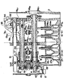
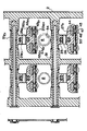
つぎに、図2は本発明装置の要部側断面図、図3は図2のA−A線およびB−B線に沿う断面図である。この実施形態では並列2気筒エンジンであって、各気筒ごとに吸気側(IN)および排気側(EX)にそれぞれ2つのバルブ(つまり4バルブ)を有している。なお、この実施形態では吸気側に適用した例とするが、吸気側および排気側の双方に適用することもできる。シリンダ内で上下に往復動するピストンの上部にシリンダヘッド2が配置され、このシリンダヘッド2内に動弁装置10が収容される。
【0029】
動弁装置10は、気筒の配列方向に沿って配置されるカム/カムシャフトユニットと、カム/カムシャフトユニットにおけるカムのカム面に押されてバルブを進退させるバルブリフタユニットと、この例では吸気制御するバルブユニットと、アクセル開度に応じてカムを変位させるアクセルシャフトユニットとを含んでいる。なお、バルブユニットについては、排気側も同様の構成であってよい。
【0030】
まずカム/カムシャフトユニットにおいて、カム高さとカム作用角が連続的に変化するように形成され、カムシャフトと一体回転するとともにその軸方向に相対移動可能に構成された立体カムを有する。この立体カムとして、バルブを開弁する開カム11およびバルブを閉弁する閉カム12を含むとともに、カムシャフトとして、開カム11および閉カム12をそれぞれスライド自在に支持する相互に平行配置された開カムシャフト13および閉カムシャフト14を含む。
【0031】
開カムシャフト13および閉カムシャフト14はそれぞれ、ベアリング15および16を介してシリンダヘッド2に回転自在に支持される。これらの開カムシャフト13および閉カムシャフト14にはそれぞれ、たとえば3条のボールスプライン13aおよび14aが形成され、そのガイドによって開カム11および閉カム12がボール17,18を介して直線運動(リニアモーション)するようになっている。なお、開カムシャフト13および閉カムシャフト14は中空構造とし、その中空内部に潤滑油路を形成して開カム11および閉カム12等にそれぞれ注油することができる。
【0032】
閉カムシャフト14の一端にはスプロケット19が固着している。排気側のカムシャフト14Exの一端にもスプロケット19Exが固着しており、図4に示すようにこれらのスプロケット19,19Exとクランクシャフト(図示せず)の一端に固着するドライブスプロケット3との間にカムチェーン4が巻回装架される。なお、図4に示されるようにチェーンガイド5、チェーンテンショナ6およびテンショナアジャスタ7等を含み、これらによりカムチェーン4が適正走行するようになっている。
【0033】
ここで、開カム11および閉カム12はいわゆる「3次元カム」として構成され、各気筒に1つずつ設けられる。開カム11および閉カム12には、開カムシャフト13および閉カムシャフト14の軸方向に緩やかに傾斜するカム面が延設され、バルブリフト量を連続的に変化させる形状に成形されている。この場合、カム高さと同時にカム作用角およびリフトタイミングも変化し、すなわちバルブリフト量が大きくなるのに従ってカム作用角も大きくなり、さらにはバルブのリフトタイミングも変化させ得るように設定されている。かかる開カム11および閉カム12を開カムシャフト13および閉カムシャフト14に沿って移動させることにより、吸気バルブのリフト量、作動角およびリフトタイミングを無段階に可変制御することができる。
【0034】
閉カムシャフト14は、エンジンのクランク軸により無端回転手段としてのカムチェーン4を介して回転駆動されるとともに、開カムシャフト13へ回転駆動力を伝達するように構成されている。すなわち開カムシャフト13および閉カムシャフト14のスプロケット19とは反対側の端部には、図3に示されるようにギヤ20,21がそれぞれ固着し、これらのギヤ20,21にアイドルギヤ22が噛合する。開カムシャフト13および閉カムシャフト14はアイドルギヤ22を介して結合し、同一方向に回転駆動される。
【0035】
なお、後述するように開カム11および閉カム12はアクセルシャフトユニットによって、それぞれ開カムシャフト13および閉カムシャフト14に沿って同期して変位するようにスライド駆動される。
【0036】
バルブリフタユニットにおいて、バルブリフタ23は概略環状を呈し、バルブリフト方向と平行に植設されたガイドピン24に沿って移動可能に装着される。この場合バルブリフタ23はその上部に、回転摺接部として構成されたタペットローラ25を有し、開カム11と閉カム12の間にそれらの双方に摺接するタペットローラ25を介置する。
【0037】
ここで、図5はバルブリフタ23の構成例を示している。バルブリフタ23はたとえばアッパハーフ23Aとロアハーフ23Bとが一体的に構成され、両側部にガイドピン24を挿通させるための挿通孔23aを有する。バルブリフタ23のロアハーフ23Bの下部両端には、バルブ(バルブステム)が取り付けられる取付ねじ孔23bが形成された一対の腕部23cが延出する。タペットローラ25はピン26を介して、そのまわりに回転自在に支持される。タペットローラ25の外周面は典型的には円弧状(R状)に形成され、つまり球状接触面を有し、開カム11および閉カム12とは点接触するようになっている。
【0038】
図2に示されるようにバルブのバルブステムの軸方向に沿って、開カムシャフト13、閉カムシャフト14およびタペットローラ25が並設され、閉カムシャフト14がシリンダの燃焼室寄りに配置される。この場合、閉カムシャフト14は、バルブリフタ23の内方もしくは内側に配置される。
【0039】
なお、本実施形態では排気側については、図2あるいは図3(図2のA−A線断面)に示されるように平板状の開カム11Exと閉カム12Exを持ち、タペットローラ25Exがそれらの双方に摺接する。タペットローラ25Exの外周面は接触平面として構成される。その他の構成は、実質的に吸気側と同様である。
【0040】
バルブユニットにおいて、それぞれのバルブステム27aがバルブガイド28によってガイドされる2つの吸気バルブ27を含んでいる。また、各バルブステム27aの上端部は、アジャストボルト29を介してバルブリフタ23の取付ねじ孔23bに取り付けられる。この場合、ロックナット30によって各バルブステム27aの上端部をバルブリフタ23に固定する。そして、図6に示すようにアジャストボルト29の上下にサークリップ201,202を装着するとともに、サークリップ201とアジャストボルト29の間にシールスプリング203(皿バネ)を介装する。このような皿バネを介装することにより、バルブ着座時のシール性を確保するが、特に加工公差によって開カム11Exおよび閉カム12Ex間に生じる隙間のばらつきを吸収し、あるいは運転使用によるバルブ傘座の磨耗に起因する隙間を吸収し得るようにしている。
【0041】
アクセルシャフトユニットにおいて、開カムシャフト13および閉カムシャフト14と平行に配置されたアクセルシャフト31と、アクセルシャフト31に固着するとともに開カムシャフト13および閉カムシャフト14の双方に連結するアクセルフォーク32を含んでいる。アクセルシャフト31はその軸方向にスライド可能にシリンダヘッド2によって支持され、一端側でネジリスプライン31aを介してドリブンギヤ33(ホイール)と係合している。ドリブンギヤ33はシリンダヘッド2に回転自在に支持され、アクセルモータ34の出力軸に固着したドライブギヤ35(ウォーム)と噛合する。
【0042】
アクセルモータ34は、アクセル変化(アクセル開度や加速・減速方向など)に対応してその出力軸が回転し、その回転はドライブギヤ35およびドリブンギヤ33を介して、アクセルシャフト31のスライド運動に変換される。この例ではアクセルモータ34はシリンダ軸線方向に沿って配置され、シリンダヘッドカバー2aによって覆われている。
【0043】
なお、たとえば自動二輪車の場合にあっては、アクセルグリップの回転操作量をアクセルモータ34の出力軸の回転量に対応させるようにしてもよい。また、アクセルモータ34を駆動する際、そのときの走行状況(出力)に合うようにコントローラ(図示せず)によって駆動制御されるようになっている。
【0044】
アクセルフォーク32は、ベアリング36,38を介してそれぞれ開カム11および閉カム12の端部に回転自在に装着されたフォークガイド37,39と係合する。これによりアクセルシャフト31がその軸方向にスライドするのに連動もしくは同期して、開カム11および閉カム12が開カムシャフト13および閉カムシャフト14に沿ってそれぞれスライドする。
【0045】
ここで、閉カムシャフト14の他端には位相センサユニットが設けられる。位相センサユニットは、閉カムシャフト14の他端に植設されたピン40とこのピン40を検出して出力信号を得る位相センサ41を含んでいる。
【0046】
上記構成において、アクセルグリップ(もしくはアクセルペダル)を操作するとアクセルモータ34が作動し、その出力軸の回転によりアクセルシャフト31がスライドする。たとえば、エンジン低速時には図3に示されるようにタペットローラ25は開カム11に対して、カム高さの低い部位に当接している。なお、そのとき閉カム12に対しては、カム高さの高い部位に当接する。この状態で加速、すなわちアクセルを開くと、アクセルモータ34の作動によりドリブンギヤ33が回転して、アクセルシャフト31は図中、右方にスライドする。
【0047】
これにより開カム11および閉カム12はアクセルフォーク32を介して、アクセルシャフト31の動きに連動してそれぞれ開カムシャフト13および閉カムシャフト14に沿って、同様に図中、右方にスライドする。なお、このとき開カム11および閉カム12のスライド量や速度は、アクセルの開度および開く速さに対応している。開カム11のスライドによりタペットローラ25は次第に、カム高さの高い部位に当接し、これにより開カム11のリフト特性に従ってバルブリフト量が増大する。一方、減速時にはアクセルを戻すことで、上記とは逆の動作でバルブリフト量を減少させる。
【0048】
ここで、上述した本発明の動弁装置あるいは内燃機関において特に、まず開カム11および閉カム12の間にタペットローラ25を挟むかたちで、これらが吸気バルブ27のバルブステム27aの軸方向に沿って直線状に配置される。吸気バルブ27を開く際には開カム11でタペットローラ25を押し下げ、閉じる際には閉カム12でタペットローラ25を押し上げる。つまり吸気バルブ27を押上げ駆動するためバルブスプリングを廃止することができ、これによりバルブ駆動時の機械的損失(メカロス)を大幅に減少する。なお、排気側についても同様に、バルブスプリングを廃止することができる。
【0049】
この場合、開カム11および閉カム12のカム形状(凸部および凹部)は、それらに挟まれるタペットローラ25の直径を含む各カム山高さの合計が、実質的に開カムシャフト13および閉カムシャフト14の軸間距離と一致するように形成される。したがって、いかなるカム位相においてもタペットローラ25は、開カム11および閉カム12の間にガタつきなく挟まれ、カム駆動機構の円滑動作が保証される。
【0050】
また、開カムシャフト13および閉カムシャフト14によりカム軸を2元化したことで、開カム11および閉カム12のカム軸方向寸法を大きくとることができる。これにより滑らかなバルブリフト特性を実現可能である。
【0051】
単一のタペットローラ25を用いることでタペット重量を軽量化し、吸排気バルブの高リフト化および高加速度化が可能になる。この場合タペットローラ25の直径を適宜設定することで、開カム11あるいは閉カム12との隙間を調整することができ、これにより吸排気バルブのリフト量を正確に制御する。
【0052】
また、開カム11、タペットローラ25および閉カム12が吸気バルブ27のバルブステム27aの軸方向に沿って直線状に配置される。このような配置関係によりバルブリフタの作動方向をバルブステム27aの方向と合致させ、実質的に直打式バルブを構成することができる。この場合、タペットローラ25と開カム11あるいは閉カム12との接触部を単一化し、軽量化を図ることができる。
【0053】
エンジンのクランク軸に近い側に配置された閉カムシャフト14に対して、カムチェーン4によりその駆動力を入力することで、カムチェーン4を短尺化することができる。この場合、開カムシャフト13および閉カムシャフト14は、アイドルギヤ22を介して同一方向に回転駆動されるため、開カム11および閉カム12に接触するタペットローラ25の回転摺動部の磨耗等を有効に低減することができる。
【0054】
バルブリフタ23は概略環状を呈し、バルブリフト方向と平行に植設されたガイドピン24に沿って移動可能である。バルブリフタ23が環状であるため閉カムシャフト14との干渉を避けるとともに、バルブリフタ23に作用する荷重を分散させて応力を均等にすることができる。
(第2の実施形態)
【0055】
つぎに、本発明による第2の実施形態を説明する。なお、上述の第1の実施形態と同一または対応する部材には同一符号を用いて、図面を参照して説明する。図7は本発明装置の要部側断面図、図8は図7のC−C線およびD−D線に沿う断面図、図9は図7のE−E線に沿う断面図、図10は図7のF−F線に沿う断面図である。この実施形態では吸気側に適用した例とするが、排気側に適用することもできる。また、シリンダ内で上下に往復動するピストンの上部にシリンダヘッド2が配置され、このシリンダヘッド2内に動弁装置が収容される。
【0056】
第2の実施形態による動弁装置は、気筒の配列方向に沿って配置されるカム/カムシャフトユニットと、カム/カムシャフトユニットにおけるカムのカム面に押されてバルブを進退させるバルブリフタユニットと、この例では吸気制御するバルブユニットと、アクセル開度に応じてカムを変位させるアクセルシャフトユニットとを含んでいる。なお、バルブユニットについては、排気側も同様の構成であってよい。
これらのうち第1の実施形態と実質的に同一のものについては、適宜その説明を省略もしくは簡略化するものとする。
【0057】
カム/カムシャフトユニットにおいて、バルブを開弁する開カム11およびバルブを閉弁する閉カム12を含むとともに、カムシャフトとして、開カム11および閉カム12をそれぞれスライド自在に支持する相互に平行配置された開カムシャフト13および閉カムシャフト14を含む。開カムシャフト13および閉カムシャフト14はそれぞれ、ベアリング15および16を介してシリンダヘッド2に回転自在に支持される。これらの開カムシャフト13および閉カムシャフト14にはそれぞれ、たとえば3条のボールスプライン13aおよび14aが形成され、そのガイドによって開カム11および閉カム12がボール17,18を介して直線運動(リニアモーション)するようになっている。なお、開カムシャフト13および閉カムシャフト14は中空構造とし、その中空内部に潤滑油路を形成して開カム11および閉カム12等にそれぞれ注油することができる。
【0058】
この実施形態では特に開カムシャフト13は、吸気側および排気側のそれぞれバルブステム軸によって挟まれる領域(所謂、Vバンク)の外側に配置される。また閉カムシャフト14は、Vバンクの内側に配置される。この場合さらに、開カムシャフト13および閉カムシャフト14が配置される平面は、シリンダ軸線と略直交するように設定される。
【0059】
閉カムシャフト14の一端にはスプロケット19が固着している。排気側のカムシャフト14Exの一端にもスプロケット19Exが固着しており、これらのスプロケット19,19Exとクランクシャフトの一端に固着するドライブスプロケット3との間にカムチェーン4が巻回装架される(図4参照)。なお、図4に示されるようにチェーンガイド5、チェーンテンショナ6およびテンショナアジャスタ7等を含み、これらによりカムチェーン4が適正走行するようになっている。
【0060】
閉カムシャフト14は、エンジンのクランク軸により無端回転手段としてのカムチェーン4を介して回転駆動されるとともに、開カムシャフト13へ回転駆動力を伝達するように構成されている。すなわち開カムシャフト13および閉カムシャフト14のスプロケット19とは反対側の端部には、図8に示されるようにギヤ20,21がそれぞれ固着し、これらのギヤ20,21にアイドルギヤ22が噛合する。開カムシャフト13および閉カムシャフト14はアイドルギヤ22を介して結合し、同一方向に回転駆動される。
【0061】
なお、後述するように開カム11および閉カム12はアクセルシャフトユニットによって、それぞれ開カムシャフト13および閉カムシャフト14に沿って同期して変位するようにスライド駆動される。
【0062】
バルブリフタユニットにおいて、本実施形態ではバルブリフタは、揺動軸のまわりに揺動可能に支持されたロッカアーム42により構成される。揺動軸として図9に示されるようにシリンダヘッド2により支持されたロッカシャフト43を含み、該ロッカシャフト43はバルブステム27aの上方かつ外側に配置される。ロッカアーム42は概略L字状を呈し(図7)、その一端にピン26を介してタペットローラ25が回転自在に支持される。ロッカアーム42はその他端でバルブステム27aに結合する。
【0063】
タペットローラ25は図7に示されるようにロッカシャフト43よりも上方に配置され、その外側および内側にそれぞれ、開カムシャフト13および閉カムシャフト14を配置する。そして、開カム11および閉カム12ならびにタペットローラ25は、シリンダ軸線と略直交する平面上に位置する。また、ロッカシャフト43およびタペットローラ25はVバンクの外側に配置される。
【0064】
ロッカアーム42の他端側においてアーム42aが延出し、このアーム42aにはロッカシャフト43と平行に、バルブステム27aの上部を両側から挟むようにピン44が横架される(図9参照)。各ピン44にはローラ45が装着される。バルブステム27aの上部に形成されたネジ部27bには、鍔部を有するアジャストナット46が螺着し、該アジャストナット46には、鍔部を有するタペットガイド47が外嵌する。アジャストナット46およびタペットガイド47はシールスプリング48を介して、ロックナット49により締付固定される。また、アジャストナット46およびタペットガイド47の鍔部相互間にローラ45を介挿することで、ロッカアーム42およびバルブステム27aが結合する。
図11に詳しく示すようにバルブステム27aのネジ部27b(雄ネジ)に対して、アジャストナット46およびロックナット49(雌ネジ)がダブル(W)ナットを構成し、これらが弛み止めとして機能する。この場合、アジャストナット46およびロックナット49の接触面がロック面となり、それらに対してシールスプリング48(皿バネ)の内径がその外側に位置する。
【0065】
なお、本実施形態では排気側については、図7あるいは図8に示されるように平板状の開カム11Exと閉カム12Exを持ち、タペットローラ25Exがそれらの双方に摺接する。タペットローラ25Exの外周面は接触平面として構成される。その他の構成は、実質的に吸気側と同様である。
排気側のバルブリフタユニットあるいはバルブユニットの構成およびそれらの結合部まわりを図10に示す。
【0066】
アクセルシャフトユニットにおいて、開カムシャフト13および閉カムシャフト14と平行に配置されたアクセルシャフト31と、アクセルシャフト31に固着するとともに開カムシャフト13および閉カムシャフト14の双方に連結するアクセルフォーク32を含んでいる。
【0067】
アクセルモータ34は、アクセル変化(アクセル開度や加速・減速方向など)に対応してその出力軸が回転し、その回転はドライブギヤ35およびドリブンギヤ33を介して、アクセルシャフト31のスライド運動に変換される。この例ではアクセルモータ34はシリンダ軸線方向に沿って配置され、シリンダヘッドカバー2aによって覆われている。
【0068】
アクセルフォーク32は、ベアリング36,38を介してそれぞれ開カム11および閉カム12の端部に回転自在に装着されたフォークガイド37,39と係合する。これによりアクセルシャフト31がその軸方向にスライドするのに連動もしくは同期して、開カム11および閉カム12が開カムシャフト13および閉カムシャフト14に沿ってそれぞれスライドする。
【0069】
第2の実施形態において、開カム11および閉カム12はアクセルフォーク32を介して、アクセルシャフト31の動きに連動してそれぞれ開カムシャフト13および閉カムシャフト14に沿って、左右にスライドする。開カム11および閉カム12の間にタペットローラ25を挟むかたちで配置され、吸気バルブ27を開く際には開カム11でタペットローラ25を揺動させ、閉じる際には閉カム12でタペットローラ25を揺動させる。
【0070】
第2の実施形態ではロッカアーム式のバルブ駆動方式とすることで、バルブリフタの大型化を有効に防止しながら、強制開閉式連続無段階リフト特性を実現する。この場合、特にロッカシャフト43およびタペットローラ25はVバンクの外側に配置され、すなわち揺動軸であるロッカシャフト43をVバンク内に配置しない構成としたことで、動弁系部材とプラグホール8との干渉を回避することができる。そして、Vバンク角を小さくし、燃焼室をコンパクトにして高出力化および高熱効率化を図ることができる。
【0071】
また、開カム11および閉カム12を並設する(シリンダ軸線と直交方向に同一面上に配置する)ことで、直打方式に比べてシリンダヘッド高を低く抑えることができる。さらに、これにより加工が容易になるとともに、加工精度が向上する上、カムホルダまわりの部品点数を削減可能である。
ロッカシャフト43のまわりに揺動するロッカアーム42を含む揺動機構の往復運動相当質量は、小さくなる。これにより鉄製ロッカであっても、往復運動相当質量自体が小さいため、バルブスプリングを用いる場合よりもバルブリフト量やバルブ開閉加速度を大幅に向上することができる。
【0072】
バルブリフタユニットあるいはバルブユニットの結合部において、アジャストナット46およびタペットガイド47はシールスプリング48を介して、ロックナット49により締付固定される。そして、アジャストナット46によってバルブ27の位置を調整可能にし、すなわちバルブシム等を用いることなく、つまりカムシャフトを分解しないでバルブ位置を調整することができる。
【0073】
この場合、シールスプリング48(皿バネ)のストロークをたとえば0.1〜0.3mm程度に設定し、バルブ無リフト域にてシールスプリング48を、その半分程度変位させる位置にアジャストナット46およびロックナット49にてバルブ位置を調整するとよい。これにより無リフト時のバルブシール性能を確保するとともに、磨耗による位置変化を吸収し、シール性能を向上することができる。また、シールスプリング48の初期荷重がある場合でもロックナット49の締付で対応することができ、特殊工具等を用いないで済む。
(第3の実施形態)
【0074】
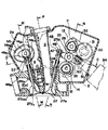
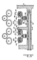
つぎに、本発明による第3の実施形態を説明する。なお、上述の第1の実施形態と同一または対応する部材には同一符号を用いて、図面を参照して説明する。図12は本発明装置の要部側断面図、図13は図12のG−G線およびH−H線に沿う断面図、図14は図12のI−I線に沿う断面図である。この実施形態では吸気側に適用した例とするが、排気側に適用することもできる。また、シリンダ内で上下に往復動するピストンの上部にシリンダヘッド2が配置され、このシリンダヘッド2内に動弁装置が収容される。
【0075】
第3の実施形態による動弁装置は、気筒の配列方向に沿って配置されるカム/カムシャフトユニットと、カム/カムシャフトユニットにおけるカムのカム面に押されてバルブを進退させるバルブリフタユニットと、この例では吸気制御するバルブユニットと、アクセル開度に応じてカムを変位させるアクセルシャフトユニットとを含んでいる。なお、バルブユニットについては、排気側も同様の構成であってよい。
これらのうち第1の実施形態と実質的に同一のものについては、適宜その説明を省略もしくは簡略化するものとする。
【0076】
カム/カムシャフトユニットにおいて、バルブを開弁する開カム11およびバルブを閉弁する閉カム12を含むとともに、カムシャフトとして、開カム11および閉カム12をそれぞれスライド自在に支持する相互に平行配置された開カムシャフト13および閉カムシャフト14を含む。開カムシャフト13および閉カムシャフト14はそれぞれ、ベアリング15および16を介してシリンダヘッド2に回転自在に支持される。これらの開カムシャフト13および閉カムシャフト14にはそれぞれ、たとえば3条のボールスプライン13aおよび14aが形成され、そのガイドによって開カム11および閉カム12がボール17,18を介して直線運動(リニアモーション)するようになっている。
【0077】
この実施形態では特に開カムシャフト13および閉カムシャフト14は、Vバンク内に配置され、この場合開カムシャフト13が閉カムシャフト14よりも上方に隔置される。さらに、開カムシャフト13および閉カムシャフト14の軸間方向が、吸気バルブ27のバルブステム27aの軸方向と略平行になるように設定される。
【0078】
閉カムシャフト14の一端にはスプロケット19が固着している。排気側のカムシャフト14Exの一端にもスプロケット19Exが固着しており、これらのスプロケット19,19Exとクランクシャフトの一端に固着するドライブスプロケット3との間にカムチェーン4が巻回装架される(図4参照)。なお、図4に示されるようにチェーンガイド5、チェーンテンショナ6およびテンショナアジャスタ7等を含み、これらによりカムチェーン4が適正走行するようになっている。
【0079】
閉カムシャフト14は、エンジンのクランク軸により無端回転手段としてのカムチェーン4を介して回転駆動されるとともに、開カムシャフト13へ回転駆動力を伝達するように構成されている。すなわち開カムシャフト13および閉カムシャフト14のスプロケット19とは反対側の端部には、図11に示されるようにギヤ20,21がそれぞれ固着し、これらのギヤ20,21にアイドルギヤ22が噛合する。開カムシャフト13および閉カムシャフト14はアイドルギヤ22を介して結合し、同一方向に回転駆動される。
【0080】
なお、後述するように開カム11および閉カム12はアクセルシャフトユニットによって、それぞれ開カムシャフト13および閉カムシャフト14に沿って同期して変位するようにスライド駆動される。
【0081】
バルブリフタユニットにおいて、本実施形態ではバルブリフタは、吸気バルブ27とプラグホール8の間に配置された揺動軸のまわりに揺動可能に支持されスイングアーム50により構成される。揺動軸として図14に示されるようにシリンダヘッド2により支持されたスイングアームシャフト51を含み、該スイングアームシャフト51はプラグホール8の至近位置に配置される。
【0082】
スイングアーム50はその先端で吸気バルブ27に結合するとともに、その途中適所にはピン26を介してタペットローラ25が回転自在に支持される。またスイングアーム50を挟んでその上方に開カムシャフト13を配置し、下方には閉カムシャフト14を配置する。
【0083】
スイングアーム50の先端にはスイングアームシャフト51と平行に、バルブステム27aの上部を両側から挟むようにピン44が横架される(図14参照)。各ピン44にはローラ45が装着される。バルブステム27aの上部に形成されたネジ部27bには、鍔部を有するアジャストナット46が螺着し、該アジャストナット46には、鍔部を有するタペットガイド47が外嵌する。アジャストナット46およびタペットガイド47はシールスプリング48を介して、ロックナット49により締付固定される。また、アジャストナット46およびタペットガイド47の鍔部相互間にローラ45を介挿することで、ロッカアーム42およびバルブステム27aが結合する。この結合構造は実質的に、第2の実施形態の場合と同様である(図11参照)。
【0084】
図12に示されるようにスイングアーム50の力点(ピン26)、作用点(ピン44)および支点(スイングアームシャフト51)は、略一直線上に配置される。この場合、スイングアーム50は支点であるスイングアームシャフト51のまわりに回動するが、そのストローク範囲内でバルブステム27aの軸線方向に対して略直交するように支点が設定される。
【0085】
なお、本実施形態では排気側については、図12あるいは図13に示されるように平板状の開カム11Exと閉カム12Exを持ち、タペットローラ25Exがそれらの双方に摺接する。タペットローラ25Exの外周面は接触平面として構成される。その他の構成部材自体は、実質的に吸気側と同様である。
排気側のバルブリフタユニットあるいはバルブユニットの構成およびそれらの結合部まわりを図14に示す。
【0086】
本実施形態では特に、排気側のカム/カムシャフトユニット(開カム11Exおよび閉カム12Ex、開カムシャフト13Exおよび閉カムシャフト14Ex等)やバルブリフタユニット(スイングアーム50Ex、スイングアームシャフト51Exおよびタペットローラ25Ex等)をVバンクの外側に配置する。この場合、開カムシャフト13および開カムシャフト13Exの軸間方向と、閉カムシャフト14および閉カムシャフト14Exの軸間方向とが相互に略平行となるように配置される。
【0087】
アクセルシャフトユニットにおいて、開カムシャフト13および閉カムシャフト14と平行に配置されたアクセルシャフト31と、アクセルシャフト31に固着するとともに開カムシャフト13および閉カムシャフト14の双方に連結するアクセルフォーク32を含んでいる。
【0088】
アクセルモータ34は、アクセル変化(アクセル開度や加速・減速方向など)に対応してその出力軸が回転し、その回転はドライブギヤ35およびドリブンギヤ33を介して、アクセルシャフト31のスライド運動に変換される。この例ではアクセルモータ34はシリンダ軸線方向に沿って配置され、シリンダヘッドカバー2aによって覆われている。
【0089】
アクセルフォーク32は、ベアリング52,53(図13参照)を介してそれぞれ開カム11および閉カム12の端部に結合する。ベアリング52およびベアリング53はそれぞれスラストニードルベアリングおよびラジアルニードルベアリングを含み、これらによりスラスト方向およびラジアル方向双方の負荷荷重に対応し得るようになっている。この場合、開カム11および閉カム12のカムロブ傾斜面により発生するスラストを受ける側にのみスラストニードルベアリングが設けられる。これによりアクセルシャフト31がその軸方向にスライドするのに連動もしくは同期して、開カム11および閉カム12が開カムシャフト13および閉カムシャフト14に沿ってそれぞれスライドする。
【0090】
ここでアクセルシャフト31は図12に示されるように、スイングアーム50の支点であるスイングアームシャフト51の上方において、開カムシャフト13および開カムシャフト13Exの軸間を結ぶ線上に配置される。また、開カムシャフト13、ピン26および閉カムシャフト14に沿った配列方向と、アクセルシャフト31、スイングアームシャフト51および閉カムシャフト14に沿った配列方向とによりV字状の配置関係となっている。
【0091】
上記の場合、プラグホール8は着脱可能に構成される。すなわち図12のようにプラグホール8を形成するプラグホールパイプ54が、シリンダヘッド2およびシリンダヘッドカバー2aの所定に着脱可能に取り付けられる。この場合、プラグホールパイプ54の装着部にはOリング55,55′が装着される。
【0092】
第3の実施形態において、開カム11および閉カム12はアクセルフォーク32を介して、アクセルシャフト31の動きに連動してそれぞれ開カムシャフト13および閉カムシャフト14に沿って、左右にスライドする。開カム11および閉カム12の間にタペットローラ25を挟むかたちで配置され、吸気バルブ27を開く際には開カム11でタペットローラ25を介してスイングアーム50を揺動させ、閉じる際には閉カム12でタペットローラ25を介してスイングアーム50を揺動させる。
【0093】
第3の実施形態ではスイングアーム式のバルブ駆動方式とするが、特に吸気系においてスイングアーム50や開カム11および閉カム12等の主要部品は、プラグホール8と吸気バルブ27(バルブステム27a)の間に配置され、すなわち吸気バルブ27の外側には実質的に部品が配置されない。これにより図12に示されるようにシリンダ軸線に対する吸気ポート9の傾斜角度αを小さくし、該吸気ポート9をシリンダ軸線側に起こすことでストレート吸気にすることができる。そしてシリンダ内でのタンブル流を増加させるとともに、吸気の吸入抵抗を小さくすることにより、高出力化およびリーンバーン化等が可能になる。
【0094】
また、スイングアーム50を挟んでその上方に開カムシャフト13を、また下方には閉カムシャフト14を配置することで、動弁機構をシリンダの燃焼室に接近配置することができる。これによりシリンダヘッド高を低く抑え、エンジンのコンパクト化および低重心化等を図ることができる。
特に吸気系の主要部品をVバンク内に配置することで、吸気側におけるシリンダヘッド2の前後長を大幅に短くすることができる。
【0095】
また、前述したようにスイングアーム50の力点、作用点および支点が略一直線上に配置され、スイングアーム50のストローク範囲内でバルブステム27aの軸線方向に対して略直交するように支点が設定される。かかる配置によりスイングアーム50を最大に軽量化し、高リフト、高開閉加速度および高回転化等を可能にする。その場合、スイングアーム50の揺動角のためにバルブステム27aに生じる曲げモーメントを小さくし、これにより該バルブステム27aのストローク作動が円滑化するとともに、バルブガイド28を磨耗を防止することができる。
【0096】
また、アクセルシャフト31をスイングアームシャフト51の上方において、開カムシャフト13および開カムシャフト13Exの軸間を結ぶ線上に配置し、開カムシャフト13、ピン26および閉カムシャフト14に沿った配列方向と、アクセルシャフト31、スイングアームシャフト51および閉カムシャフト14に沿った配列方向とによりV字状の配置関係とする。このような配置構成により、Vバンク内の空間を有効利用し、シリンダヘッド2のコンパクト化を図ることができる。
【0097】
排気側のカム/カムシャフトユニットやバルブリフタユニットをVバンクの外側に配置し、開カムシャフト13および開カムシャフト13Exの軸間方向と、閉カムシャフト14および閉カムシャフト14Exの軸間方向とが相互に略平行となるように配置する。これによりカムホルダの加工が容易になるとともに、Vバンク角を小さくしつつプラグホール8を配設することができる。
【0098】
そのプラグホール8を形成するプラグホールパイプ54を、シリンダヘッド2およびシリンダヘッドカバー2aに着脱可能に取り付けることで、開カム11および閉カム12まわりの部品組付性を向上することができる。また、プラグホールパイプ54を薄肉化することにより、Vバンク角を小さくすることができる。
【0099】
また、アクセルフォーク32と開カム11および閉カム12との間にスラストニードルベアリングおよびラジアルニードルベアリングが装着され、開カム11および閉カム12のカムロブ傾斜面により発生するスラストを受ける側にのみスラストニードルベアリングが設けられる。これによりアクセルフォーク32の爪部の外径を小さくし、Vバンク角を小さくすることができる。また、該爪部のスライドの幅をスラストニードルベアリング1個分狭くすることができ、開カム11および閉カム12のスライド量を大きく確保することができる。
(第4の実施形態)
【0100】
つぎに、本発明による第4の実施形態を説明する。なお、上述の第1の実施形態と同一または対応する部材には同一符号を用いて、図面を参照して説明する。図15は本発明装置の要部側断面図、図16は図15のJ−J線およびK−K線に沿う断面図、図17は図15のL−L線に沿う断面図ある。この実施形態では、シリンダ内で上下に往復動するピストンの上部にシリンダヘッド2が配置され、このシリンダヘッド2内に動弁装置が収容される。
【0101】
第4の実施形態による動弁装置は、気筒の配列方向に沿って配置されるカム/カムシャフトユニットと、カム/カムシャフトユニットにおけるカムのカム面に押されてバルブを進退させるバルブリフタユニットと、この例では吸気制御するバルブユニットと、アクセル開度に応じてカムを変位させるアクセルシャフトユニットとを含んでいる。
これらのうち第1の実施形態と実質的に同一のものについては、適宜その説明を省略もしくは簡略化するものとする。
【0102】
カム/カムシャフトユニットにおいて、バルブを開弁する開カム11およびバルブを閉弁する閉カム12を含むとともに、カムシャフトとして、開カム11および閉カム12をそれぞれスライド自在に支持する相互に平行配置された開カムシャフト13および閉カムシャフト14を含む。開カムシャフト13および閉カムシャフト14はそれぞれ、ベアリング15および16を介してシリンダヘッド2に回転自在に支持される。これらの開カムシャフト13および閉カムシャフト14にはそれぞれ、たとえば3条のボールスプライン13aおよび14aが形成され、そのガイドによって開カム11および閉カム12がボール17,18を介して直線運動(リニアモーション)するようになっている。
【0103】
開カムシャフト13および閉カムシャフト14は、Vバンク内に配置される。この場合開カムシャフト13が閉カムシャフト14よりも上方に隔置される。さらに、開カムシャフト13および閉カムシャフト14の軸間方向が、吸気バルブ27のバルブステム27aの軸方向と略平行になるように設定される。
【0104】
閉カムシャフト14の一端にはスプロケット19が固着している。排気側のカムシャフト14Exの一端にもスプロケット19Exが固着しており、これらのスプロケット19,19Exとクランクシャフトの一端に固着するドライブスプロケット3との間にカムチェーン4が巻回装架される(図4参照)。なお、図4に示されるようにチェーンガイド5、チェーンテンショナ6およびテンショナアジャスタ7等を含み、これらによりカムチェーン4が適正走行するようになっている。
【0105】
閉カムシャフト14は、エンジンのクランク軸により無端回転手段としてのカムチェーン4を介して回転駆動されるとともに、開カムシャフト13へ回転駆動力を伝達するように構成されている。すなわち開カムシャフト13および閉カムシャフト14のスプロケット19とは反対側の端部には、図16に示されるようにギヤ20,21がそれぞれ固着し、これらのギヤ20,21にアイドルギヤ22が噛合する。開カムシャフト13および閉カムシャフト14はアイドルギヤ22を介して結合し、同一方向に回転駆動される。
【0106】
なお、後述するように開カム11および閉カム12はアクセルシャフトユニットによって、それぞれ開カムシャフト13および閉カムシャフト14に沿って同期して変位するようにスライド駆動される。
【0107】
バルブリフタユニットにおいてバルブリフタは、吸気バルブ27とプラグホール8の間に配置された揺動軸のまわりに揺動可能に支持されスイングアーム50により構成される。揺動軸として図17に示されるように、シリンダヘッド2により支持されたスイングアームシャフト51を含み、該スイングアームシャフト51はプラグホール8の至近位置に配置される。
【0108】
スイングアーム50はその先端で吸気バルブ27に結合するとともに、その途中適所にはピン26を介してタペットローラ25が回転自在に支持される。またスイングアーム50を挟んでその上方に開カムシャフト13を配置し、下方には閉カムシャフト14を配置する。
【0109】
スイングアーム50の先端にはスイングアームシャフト51と平行に、バルブステム27aの上部を両側から挟むようにピン44が横架される(図17参照)。各ピン44にはローラ45が装着される。バルブステム27aの上部に形成されたネジ部27bには、鍔部を有するアジャストナット46が螺着し、該アジャストナット46には、鍔部を有するタペットガイド47が外嵌する。アジャストナット46およびタペットガイド47はシールスプリング48を介して、ロックナット49により締付固定される。また、アジャストナット46およびタペットガイド47の鍔部相互間にローラ45を介挿することで、ロッカアーム42およびバルブステム27aが結合する。この結合構造は実質的に、第2の実施形態の場合と同様である(図11参照)。
【0110】
図15に示されるようにスイングアーム50の力点(ピン26)、作用点(ピン44)および支点(スイングアームシャフト51)は、略一直線上に配置される。この場合、スイングアーム50は支点であるスイングアームシャフト51のまわりに回動するが、そのストローク範囲内でバルブステム27aの軸線方向に対して略直交するように支点が設定される。
【0111】
なお、本実施形態では排気側については、図15あるいは図16に示されるように平板状の開カム11Exと閉カム12Exを持ち、タペットローラ25Exがそれらの双方に摺接する。タペットローラ25Exの外周面は接触平面として構成される。その他の構成部材自体は、実質的に吸気側と同様である。
排気側のバルブリフタユニットあるいはバルブユニットの構成およびそれらの結合部まわりを図17に示す。
【0112】
排気側のカム/カムシャフトユニット(開カム11Exおよび閉カム12Ex、開カムシャフト13Exおよび閉カムシャフト14Ex等)やバルブリフタユニット(タペットローラ25Ex等)をVバンクの外側に配置する。この場合、開カムシャフト13および開カムシャフト13Exの軸間方向と、閉カムシャフト14および閉カムシャフト14Exの軸間方向とが相互に略平行となるように配置される。
【0113】
本実施形態では特に、スイングアーム50Exは吸気側のスイングアーム50と同軸に、すなわち吸気側のスイングアームシャフト51のまわりに揺動可能に支持される。この場合、図17に示されるようにプラグホール8の両側を通すかたちで、一対のスイングアーム50Exが支持される。各スイングアーム50Exは、その先端でピン26Exを介してタペットローラ25Exを回転自在に支持するとともに、その途中適所で排気バルブ27Exに結合する。
【0114】
また、スイングアーム50Exを挟んでその上方に開カム11Exを配置し、下方には閉カム12Exを配置する。図15から分かるように、これら開カム11Exおよび閉カム12Exのカム外周部プロフィールとバルブステム27aとが側面視でオーバラップするように配置される。
【0115】
アクセルシャフトユニットにおいて、開カムシャフト13および閉カムシャフト14と平行に配置されたアクセルシャフト31と、アクセルシャフト31に固着するとともに開カムシャフト13および閉カムシャフト14の双方に連結するアクセルフォーク32を含んでいる。
【0116】
アクセルモータ34は、アクセル変化(アクセル開度や加速・減速方向など)に対応してその出力軸が回転し、その回転はドライブギヤ35およびドリブンギヤ33を介して、アクセルシャフト31のスライド運動に変換される。この例ではアクセルモータ34はシリンダ軸線方向に沿って配置され、シリンダヘッドカバー2aによって覆われている。
【0117】
アクセルフォーク32は、ベアリング52,53を介してそれぞれ開カム11および閉カム12の端部に結合する。ベアリング52およびベアリング53はそれぞれスラストニードルベアリングおよびラジアルニードルベアリングを含み、これらによりスラスト方向およびラジアル方向双方の負荷荷重に対応し得るようになっている。この場合、開カム11および閉カム12のカムロブ傾斜面により発生するスラストを受ける側にのみスラストニードルベアリングが設けられる。これによりアクセルシャフト31がその軸方向にスライドするのに連動もしくは同期して、開カム11および閉カム12が開カムシャフト13および閉カムシャフト14に沿ってそれぞれスライドする。
【0118】
ここでアクセルシャフト31は図15に示されるように、スイングアーム50の支点であるスイングアームシャフト51の上方において、開カムシャフト13および開カムシャフト13Exの軸間を結ぶ線上に配置される。また、開カムシャフト13、ピン26および閉カムシャフト14に沿った配列方向と、アクセルシャフト31、スイングアームシャフト51および閉カムシャフト14に沿った配列方向とによりV字状の配置関係となっている。
【0119】
上記の場合、プラグホール8は着脱可能に構成される。すなわち図15のようにプラグホール8を形成するプラグホールパイプ54が、シリンダヘッド2およびシリンダヘッドカバー2aの所定に着脱可能に取り付けられる。この場合、プラグホールパイプ54の装着部にはOリング55,55′が装着される。
【0120】
第4の実施形態において、開カム11および閉カム12はアクセルフォーク32を介して、アクセルシャフト31の動きに連動してそれぞれ開カムシャフト13および閉カムシャフト14に沿って、左右にスライドする。開カム11および閉カム12の間にタペットローラ25を挟むかたちで配置され、吸気バルブ27を開く際には開カム11でタペットローラ25を介してスイングアーム50を揺動させ、閉じる際には閉カム12でタペットローラ25を介してスイングアーム50を揺動させる。
【0121】
また、排気側において排気バルブ27Exを開く際には開カム11Exでタペットローラ25Exを介してスイングアーム50Exを揺動させ、閉じる際には閉カム12Exでタペットローラ25Exを介してスイングアーム50Exを揺動させる。この場合、スイングアーム50Exは吸気側のスイングアームシャフト51のまわりに揺動する。
【0122】
第4の実施形態では特に、排気側のスイングアーム50Exを吸気側のスイングアーム50と同軸に配置することで、閉カムシャフト14および閉カムシャフト14Exを排気バルブ27Exのバルブステム27aと干渉しない限り、シリンダ軸線側に配設することができる。これによりシリンダヘッド2の前後長を大幅に短くすることができる。また、スイングアームシャフト51を吸気側と排気側で共用することで、加工性が向上するとともに軽量化を図ることができる。なお、開カム11Exおよび閉カム12Exのカム外周部プロフィールとバルブステム27aとをオーバラップさせることでも、同様な効果が得られる。
(第5の実施形態)
【0123】
つぎに、本発明による第5の実施形態を説明する。なお、上述の第1の実施形態と同一または対応する部材には同一符号を用いて、図面を参照して説明する。図18は本発明装置の要部側断面図、図19は図18のM−M線およびN−N線に沿う断面図、図20は図18のO−O線に沿う断面図、図21は図18のP−P線に沿う断面図ある。この実施形態ではシリンダ内で上下に往復動するピストンの上部にシリンダヘッド2が配置され、このシリンダヘッド2内に動弁装置が収容される。
【0124】
第5の実施形態による動弁装置は、気筒の配列方向に沿って配置されるカム/カムシャフトユニットと、カム/カムシャフトユニットにおけるカムのカム面に押されてバルブを進退させるバルブリフタユニットと、この例では吸気制御するバルブユニットと、アクセル開度に応じてカムを変位させるアクセルシャフトユニットとを含んでいる。
これらのうち第1の実施形態と実質的に同一のものについては、適宜その説明を省略もしくは簡略化するものとする。
【0125】
カム/カムシャフトユニットにおいて、バルブを開弁する開カム11およびバルブを閉弁する閉カム12を含むとともに、カムシャフトとして、開カム11および閉カム12をそれぞれスライド自在に支持する相互に平行配置された開カムシャフト13および閉カムシャフト14を含む。開カムシャフト13および閉カムシャフト14はそれぞれ、ベアリング15および16を介してシリンダヘッド2に回転自在に支持される。これらの開カムシャフト13および閉カムシャフト14にはそれぞれ、たとえば3条のボールスプライン13aおよび14aが形成され、そのガイドによって開カム11および閉カム12がボール17,18を介して直線運動(リニアモーション)するようになっている。
【0126】
開カムシャフト13および閉カムシャフト14は、Vバンクの外側、すなわち吸気バルブ27のバルブステム27aの外側に配置される。この場合、開カムシャフト13が閉カムシャフト14よりも上方に隔置される。さらに、開カムシャフト13および閉カムシャフト14の軸間方向が、吸気バルブ27のバルブステム27aの軸方向と略平行になるように設定される。
【0127】
閉カムシャフト14の一端にはスプロケット19が固着している。排気側のカムシャフト14Exの一端にもスプロケット19Exが固着しており、これらのスプロケット19,19Exとクランクシャフトの一端に固着するドライブスプロケット3との間にカムチェーン4が巻回装架される(図4参照)。なお、図4に示されるようにチェーンガイド5、チェーンテンショナ6およびテンショナアジャスタ7等を含み、これらによりカムチェーン4が適正走行するようになっている。
【0128】
閉カムシャフト14は、エンジンのクランク軸により無端回転手段としてのカムチェーン4を介して回転駆動されるとともに、開カムシャフト13へ回転駆動力を伝達するように構成されている。すなわち開カムシャフト13および閉カムシャフト14のスプロケット19とは反対側の端部には、図19に示されるようにギヤ20,21がそれぞれ固着し、これらのギヤ20,21にアイドルギヤ22が噛合する。開カムシャフト13および閉カムシャフト14はアイドルギヤ22を介して結合し、同一方向に回転駆動される。
【0129】
なお、後述するように開カム11および閉カム12はアクセルシャフトユニットによって、それぞれ開カムシャフト13および閉カムシャフト14に沿って同期して変位するようにスライド駆動される。
【0130】
バルブリフタユニットにおいてバルブリフタは、開カムシャフト13および閉カムシャフト14の外側に配置された揺動軸のまわりに揺動可能に支持されスイングアーム50により構成される。揺動軸として図20に示されるように、シリンダヘッド2により支持されたスイングアームシャフト51を含む。スイングアーム50はその先端で吸気バルブ27に結合するとともに、その途中適所にはピン26を介してタペットローラ25が回転自在に支持される。またスイングアーム50を挟んでその上方に開カムシャフト13を配置し、下方には閉カムシャフト14を配置する。
【0131】
スイングアーム50の先端にはスイングアームシャフト51と平行に、バルブステム27aの上部を両側から挟むようにピン44が横架される(図20参照)。各ピン44にはローラ45が装着される。バルブステム27aの上部に形成されたネジ部27bには、鍔部を有するアジャストナット46が螺着し、該アジャストナット46には、鍔部を有するタペットガイド47が外嵌する。アジャストナット46およびタペットガイド47はシールスプリング48を介して、ロックナット49により締付固定される。また、アジャストナット46およびタペットガイド47の鍔部相互間にローラ45を介挿することで、ロッカアーム42およびバルブステム27aが結合する。この結合構造は実質的に、第2の実施形態の場合と同様である(図11参照)。
【0132】
なお、本実施形態では排気側については、カムシャフト14Exに所定間隔おいて平板状の溝カム56が支持され、そのカム溝56aに係合するタペット57を介して排気バルブ27Exを駆動するようになっている。
【0133】
この場合、バルブステム27aExのネジ部27bExにアジャストナット46Exが螺着する。タペット57およびバルブステム27aExはシールスプリング48Exを介して、ロックナット49Exにより締付固定される。タペット57の端部は、ローラ58を介してカム溝56aと係合する。タペット57はガイドシャフト59を介して、バルブステム27aExの軸方向にガイドされる。
【0134】
ここで本実施形態では特に、図18に示されるようにプラグホール8および吸気ポート9をVバンク内に配置するとともに、それらを略平行にして傾斜配置する。この場合、プラグホール8および吸気ポート9が側面視で部分的に重なるように、上面視でプラグホール8を吸気ポート9間の中央付近に配置する(図20、図21)。
【0135】
アクセルシャフトユニットにおいて、開カムシャフト13および閉カムシャフト14と平行に配置されたアクセルシャフト31と、アクセルシャフト31に固着するとともに開カムシャフト13および閉カムシャフト14の双方に連結するアクセルフォーク32を含んでいる。
【0136】
アクセルモータ34は、アクセル変化(アクセル開度や加速・減速方向など)に対応してその出力軸が回転し、その回転はドライブギヤ35およびドリブンギヤ33を介して、アクセルシャフト31のスライド運動に変換される。この例ではアクセルシャフト31は開カムシャフト13よりも外側に配置され、アクセルモータ34はシリンダ軸線に対して傾斜して配置される。
【0137】
アクセルフォーク32は、ベアリング52,53を介してそれぞれ開カム11および閉カム12の端部に結合する。ベアリング52およびベアリング53はそれぞれスラストニードルベアリングおよびラジアルニードルベアリングを含み、これらによりスラスト方向およびラジアル方向双方の負荷荷重に対応し得るようになっている。この場合、開カム11および閉カム12のカムロブ傾斜面により発生するスラストを受ける側にのみスラストニードルベアリングが設けられる。これによりアクセルシャフト31がその軸方向にスライドするのに連動もしくは同期して、開カム11および閉カム12が開カムシャフト13および閉カムシャフト14に沿ってそれぞれスライドする。
【0138】
上記構成において、吸気ポート9の軸線を略シリンダ軸線方向に設定することができるため吸入効率を向上させ、出力や燃費性能を大幅に向上することができる。また、開カムシャフト13および閉カムシャフト14を吸気バルブ27の傘部付近に近接配置しても、それらが吸気ポート9と干渉することはない。これによりシリンダヘッド高を低く抑えるとともに、バルブステム27aを短くすることができ、高回転化および高加速度化を可能にするバルブ開閉を行なうことができる。
【0139】
また、プラグホール8および吸気ポート9を略平行に配置することによりVバンク角を狭く設定し、シリンダヘッド2をコンパクトに構成するとともに、燃焼室面積を小さくすることで燃焼効率を向上することができる。
【0140】
つぎに、本発明による動弁装置における典型的な変形例を説明する。
(変形例1)
この例ではバルブステム上部にスイングアーム式の開カム用タペットローラおよび開カムを順に配置し、バルブステム上部に開カム用ロッカアーム作用点(開リフトローラ)を配置する。また、ロッカアーム支点に対して作用点の反対側に力点(タペットローラ)を配置し、これに接する開カムをプラグホールに対して開カムの反対側に配置する。
【0141】
この例によれば、プラグホールと吸気ポートの間には開カムシャフトおよびスイングアームのみの配置となるため、その前後方向寸法を小さくすることができる。これによりシリンダ軸線に対する吸気ポートの傾斜角度を小さくするとともに、シリンダヘッド高を低く抑えることができる。また、タペット部の下側には閉リフトローラのみの配置となるため、バルブステム長を現状のバルブスプリング仕様並みのものと同程度に短くすることができる。
【0142】
また、この例では吸気側の閉ロッカシャフト(支点)をエンジン側面視にて、プラグホールとオーバラップする位置に配置する。
これによりロッカアーム長を短くすることができ、高回転化、高リフト化および高加速度化を図ることができる。また、閉カムをプラグホールに近接配置することができ、シリンダヘッドの前後長をコンパクトにすることができる。
【0143】
また、この例では吸気側閉カムの下側にエンジン側面視にて、吸気側閉タペットローラの揺動軌跡とオーバラップするように排気側にて板状の溝カムを配置する。
これによりバルブステム長を現状のバルブスプリング仕様並みのものよりも実質的に短くすることができる。また、可変ストローク化されてはいないが、開カムおよび閉カムを併用することができ、カム軸を1本省略することでシリンダヘッドまわりをコンパクトにする。
【0144】
また、この例では吸気側開スイングアームの力点(タペットローラ)、作用点(リフトローラ)、開カム軸および吸気側閉ロッカアーム作用点(リフトローラ)の中心を略バルブステム軸上に配置する。
これによりバルブステムに作用する曲げモーメントを小さくすることができ、円滑作動を保証することともに耐久性を向上させる。
【0145】
また、この例では吸気側タペットローラとリフトローラを同軸上に配置する。これにより2つのローラを同一軸に配置することで、軽量化やコストダウンを図ることができる。
【0146】
また、この例では吸気側ロッカアームの形状をプラグホールを囲み、ロの字状とし、すなわち複数のバルブを1つのタペットローラでリフトさせるように一体化する。
これによりタペットローラ1個により複数のバルブをリフトすることができる。また、高剛性化を図ることができる。
【0147】
また、この例ではシリンダ軸線に対してバルブの外側に一対の円板状の溝カムを配置し、タペットを両持ち式にてリフトさせる。
これにより両持ちすることでバルブリフト作動をスムースに行なうことができる。また、溝カムがその外側のベアリング軸受に近く配置されるため、曲げモーメントが小さくなり、カムシャフトの径を小さくし、その分だけ溝カムの外径を小さくしてシリンダヘッドまわりをコンパクトにすることができる。
【0148】
(変形例2)
この例ではバルブステム上部にスイングアーム式の開カム用タペットローラおよび開カムを順に配置し、バルブステム上部に開カム用ロッカアーム作用点(開リフトローラ)を配置する。また、ロッカアーム支点をVバンク内に配置し、その支点に対して作用点の反対側に力点(タペットローラ)を配置し、これに接する閉カムをプラグホールに対して開カムの反対側に配置する。さらに、開スイングアームの支点(軸)をVバンク内に配置する。
【0149】
この例によれば、吸気側バルブステムと吸気ポートの間にスイングアームシャフトがないため、シリンダ軸に対する吸気ポート傾斜角度を小さくすることができ、シリンダヘッドをさらにコンパクトにするとともに、タンブル流を強くするとともに高出力化を図ることができる。
【0150】
また、この例ではロッカアーム支点とスイングアーム支点を同一軸とする。この場合、ロッカアーム支点およびスイングアーム支点をエンジン側面視にて、プラグホールとオーバラップするように配置する。
これによりロッカアームおよびスイングアーム長を短くし、高回転化を図るとともに、シリンダヘッドの前後長をコンパクトにすることができる。また、軸を共用することで加工費用、重量および組立工数等を削減することができる。
【0151】
また、この例では開カム用スイングアームの支点を閉カム用ロッカアームのアーム部に設ける。
これによりスイングアームをさらにコンパクト化し、往復運動量を軽減することで高回転化および高開閉加速度化を図ることができる。また、スイングアームをロッカアームに部組可能にし、組立性を向上することができる。
【0152】
(変形例3)
この例では吸気バルブを強制開閉するが、開カム側を直打式にするとともに、閉カム側をロッカアーム式に構成する。
【0153】
この例によれば、往復運動部の重量を軽減することでリフト量および開閉加速度を高め、高出力化や高回転化および図ることができる。また、開タペットが直線的にストローク作動するため、さらに正確なリフト作動が得られる。
【0154】
また、この例ではタペットガイドを複数のバルブステム軸間に設ける。
これによりタペットガイド溝の開放端がリフト小側、すなわちガイドにかかる負荷が小さい側に配置される。したがって、ガイドの変形を小さくすることができ、軽量化を図ることができる。また、リフト大側では溝の底部となり、剛性を有する部分で負荷が最大となり、負荷が大きくなっても変形量が小さい。
【0155】
ところで、バルブスプリング仕様のエンジンにあってはバルブステム軸間にガイドを排気位置することがでいないため、タペットおよびカム間にガイドを設けていない。ガイドの閉じ端肉厚とリフト分だけタペットローラ径を大きくする必要があり、タペット重量が増加するとともに、シリンダヘッド高が高くなる。これに対して本発明ではステム間にガイドを設けることで、かかる不都合を解消することができる。
【0156】
また、この例ではバルブステム軸方向視にて、閉ロッカアームのプロフィールに重ならないようにタペットガイドを形成する。そして、エンジン側面視にてロッカアームとタペットが重なるように配置する。
これによりシリンダヘッド高が低くなるとともに、ガイドの取付座を高くすることができるためポートの傾斜角度を小さくすることができる。また、ロッカアームを外さなくてもタペットガイドの分解整備が可能になる。
【0157】
(変形例4)
この例では吸気バルブを強制開閉するが、閉カム側をロッカアーム式に構成するとともに、吸気側の開カムおよび閉カムシャフトを近接配置し、プラグホールを閉カムシャフトと排気側のカムシャフトの間に配置する。なお、吸気側においてはスイングアーム式あるいは直打式のいずれであってもよい。
【0158】
この例によれば、アクセルフォークをコンパクトにすることができ、剛性を高めるとともに、開閉カムを正確に同調させることができる。また、装置重量やコストを低減することができる。さらに、閉カム駆動ギヤをコンパクトにするとともに、アイドルギヤを廃止することができる。
【0159】
また、この例ではプラグホールを前後面視にてシリンダ軸線に対して傾斜させ、側面視にては閉タペットローラ軌跡とオーバラップさせる。
これによりVバンク角を小さくすることができ、シリンダヘッドをコンパクト化するとともに、燃焼室容積に対する表面積(SV値)を小さくして燃焼効率や出力を向上させる。
【0160】
以上、本発明を種々の実施形態とともに説明したが、本発明はこれらの実施形態にのみ限定されるものではなく、本発明の範囲内で変更等が可能である。
たとえば上記実施形態で説明した具体的な数値例等は、必ずしもこれに限定されず、必要に応じて変更可能である。また、各実施形態において、2気筒エンジンの場合の例を説明したが、本発明は単気筒または3気筒以上のエンジンに対しても有効に適用可能である。
【0161】
【発明の効果】
以上説明したように本発明によれば、この種の動弁装置においてアクセル開度に応じてバルブリフト量、作動角およびリフトタイミングを無段階可変制御する。この場合、特に吸気バルブを押上げ駆動するためバルブスプリングを廃止することができ、バルブ駆動時の機械的損失を大幅に減少する。また、開カムシャフトおよび閉カムシャフトによりカム軸を2元化したことで、開カムおよび閉カムのカム軸方向寸法を大きくとることができる。これにより滑らかなバルブリフト特性を実現可能である。この場合、単一のタペットローラを用いることでタペット重量を軽量化し、吸排気バルブの高リフト化および高加速度化が可能になる。
【0162】
また、たとえば特に開カム、タペットローラおよび閉カムが吸気バルブのバルブステムの軸方向に沿って直線状に配置される。このような配置関係によりバルブリフタの作動方向をバルブステムの方向と合致させ、実質的に直打式バルブを構成することができる
【図面の簡単な説明】
【図1】本発明の適用例に係るエンジンまわりを含む自動二輪車の構成例を示す図である。
【図2】本発明の第1の実施形態における動弁装置の要部側断面図である。
【図3】図2のA−A線およびB−B線に沿う断面図である。
【図4】本発明の動弁装置に係るカムシャフトの回転駆動系を示す図である。
【図5】本発明の第1の実施形態に係るバルブリフタの構成例を示す正面図および側面図である。
【図6】本発明の実施形態におけるバルブステムおよびバルブリフタの結合構造例を示す図である。
【図7】本発明の第2の実施形態における動弁装置の要部側断面図である。
【図8】図7のC−C線およびD−D線に沿う断面図である。
【図9】図7のE−E線に沿う断面図である。
【図10】図7のF−F線に沿う断面図である。
【図11】本発明の実施形態におけるバルブステムおよびバルブリフタの結合構造例を示す図である。
【図12】本発明の第3の実施形態における動弁装置の要部側断面図である。
【図13】図12のG−G線およびH−H線に沿う断面図である。
【図14】図12のI−I線に沿う断面図である。
【図15】本発明の第4の実施形態における動弁装置の要部側断面図である。
【図16】図15のJ−J線およびK−K線に沿う断面図である。
【図17】図15のL−L線に沿う断面図である。
【図18】本発明の第5の実施形態における動弁装置の要部側断面図である。
【図19】図18のM−M線およびN−N線に沿う断面図である。
【図20】図18のO−O線に沿う断面図である。
【図21】図18のN−P線に沿う断面図である。
【符号の説明】
1 エンジンユニット、2 シリンダヘッド、2a シリンダヘッドカバー、3ドライブスプロケット、4 カムチェーン、5 チェーンガイド、6 チェーンテンショナ、7 テンショナアジャスタ、8 プラグオール、9 吸気ポート、10 動弁装置、11 開カム、12 閉カム、13 開カムシャフト、14 閉カムシャフト、15,16 ベアリング、17,18 ボール、19 スプロケット、20,21 ギヤ、22 アイドルギヤ、23 バルブリフタ、24 ガイドピン、25 タペットローラ、27 吸気バルブ、27a バルブステム、28 バルブガイド、29 アジャストボルト、30 ロックナット、31 アクセルシャフト、32 アクセルフォーク、33 ドリブンギヤ、34 アクセルモータ、35 ドライブギヤ、36,38 ベアリング、37,39 フォークガイド、40 ピン、41 位相センサ、42 ロッカアーム、43 ロッカシャフト、44 ピン、45 ローラ、46 アジャストナット、47 タペットガイド、48 シールスプリング、49 ロックナット、50 スイングアーム、51 スイングアームシャフト、54 プラグホールパイプ、56 溝カム、57 タペット、58 ローラ、59 ガイドシャフト、100 自動二輪車、101 車体フレーム、102 ステアリングヘッドパイプ、103 フロントフォーク、104 ハンドルバー、106 前輪、108 ブレーキディスク、109 スイングアーム、110 リヤショックアブソーバ、111 後輪、112 チェーン、113 ドリブンスプロケット、114 エアクリーナ、115 吸気管、116 排気管、117 燃料タンク、118 シート、119 シートカウル、120 ヘッドランプ、121 メータユニット、125 ラジエータ。[0001]
TECHNICAL FIELD OF THE INVENTION
The present invention relates to a valve train for variably controlling a valve lift, a lift timing, and an operating angle in accordance with an accelerator opening in an internal combustion engine of a motorcycle or an automobile.
[0002]
[Prior art]
In this type of internal combustion engine, recently, a combination of variable phase and cam switching has begun to appear, and thereafter, there has been proposed a system using a three-dimensional cam that continuously varies the operating angle and the lift amount. For example, there is a type in which a follow-up mechanism for a change in contact angle is provided at the top of a direct hit type cylindrical tappet, and a valve lift is continuously variable by sliding a three-dimensional cam in an axial direction.
[0003]
When the lift characteristics (valve lift amount, lift timing and operating angle) are continuously and continuously variablely controlled using a three-dimensional cam or the like, when the valve closing operation is performed by the elasticity of the spring, the performance of the spring is changed to the lift characteristic. It has a significant effect. Therefore, the engine output may be sacrificed because it is necessary to keep the valve jump, balance, and the like within an allowable range. Particularly, in an engine having a large valve diameter or a large cylinder diameter, it is difficult to cope with a high rotation, a high valve lift, or a high acceleration.
[0004]
Therefore, for example, in a valve train according to Japanese Patent Application Laid-Open No. 3-156110 or Japanese Patent Application Laid-Open No. 5-321617, a valve-opening cam and a valve-closing cam are arranged on the same cam shaft, and a rocker arm type intake / exhaust valve is provided. Is known. According to this device, the valve spring can be eliminated.
[0005]
[Problems to be solved by the invention]
In this conventional example, since the valve-opening cam and the valve-closing cam are arranged on the same camshaft as described above, the dimension in the camshaft direction becomes large. Particularly, in the case of a three-dimensional cam or a three-dimensional cam that is long in the cam axis direction, the length of the cam axis direction becomes extremely long due to such a cam arrangement, and the cylinder head must be enlarged as it is. There is a problem.
[0006]
The present invention has been made in view of the above circumstances, and has as its object to provide a valve operating device capable of always ensuring proper and smooth valve operation and effectively achieving compactness and the like, and an internal combustion engine including the same.
[0007]
[Means for Solving the Problems]
The valve gear of the present invention is formed such that a cam height and a cam working angle are continuously changed, and is configured to rotate integrally with a camshaft and to be relatively movable in the axial direction thereof. A valve lifter that is pressed against a cam surface to advance and retract a valve, wherein the three-dimensional cam includes an open cam for opening the valve and a closed cam for closing the valve, and the cam The shaft includes an open cam shaft and a closed cam shaft which are slidably supported on the open cam and the closed cam, respectively, and which are slidably supported between the open cam and the closed cam. The rotary sliding contact portion of the valve lifter is interposed.
[0008]
Further, in the valve gear of the present invention, the open camshaft, the closed camshaft, and the rotary sliding contact portion are arranged side by side along the axial direction of the valve stem of the valve, and the closed camshaft is connected to a combustion chamber of a cylinder. It is characterized by being placed closer.
[0009]
Further, in the valve operating device of the present invention, the valve lifter is movably held along a guide pin provided in parallel with a lift direction of the valve, and the closed camshaft is disposed inside the valve lifter. It is characterized by the following.
[0010]
Further, in the valve gear of the present invention, the valve lifter includes a rocker arm supported so as to be swingable around a swing axis, the rocker arm having the rotary sliding contact portion at one end, and the rocker arm at the other end. It is characterized by being connected to a valve.
[0011]
Further, in the valve gear of the present invention, the swing shaft is arranged above and outside the valve stem, and the rotary sliding contact portion is arranged above the swing shaft, and The open camshaft and the closed camshaft are disposed outside and inside, respectively.
[0012]
Further, in the valve operating device of the present invention, the valve lifter includes a swing arm supported swingably around a swing shaft disposed between the valve and the plug hole, and the swing arm has a tip at the tip thereof. In addition to being connected to a valve, the rotary sliding contact portion is provided at an appropriate position on the way, the open camshaft is disposed above the swing arm, and the closed camshaft is disposed below the swing arm.
[0013]
Further, in the valve train of the present invention, the closed camshaft is configured to be rotationally driven by an engine crankshaft through an endless rotating means, and to transmit a rotational driving force to the open camshaft. It is characterized by the following.
[0014]
Further, in the valve gear of the present invention, the open camshaft and the closed camshaft are connected via an idle gear, and are driven to rotate in the same direction.
[0015]
Further, in the valve gear of the present invention, the open cam and the closed cam are slidably driven so as to be displaced synchronously along the open cam shaft and the closed cam shaft, respectively.
[0016]
Further, an internal combustion engine of the present invention is an internal combustion engine in which intake and exhaust are controlled by an intake valve and an exhaust valve, and is provided with any one of the above-described valve operating devices on an intake side or an exhaust side. .
[0017]
According to the present invention, in this type of engine, the valve lift and the operating angle are steplessly variably controlled in accordance with the accelerator opening. In this case, particularly when the intake valve is opened, the tappet roller is pushed down by the opening cam, and when it is closed, the tappet roller is pushed up by the closing cam. As a result, the valve spring for driving the intake valve up can be eliminated, and the mechanical loss at the time of driving the valve is greatly reduced.
[0018]
In addition, since the camshaft is dualized by the open camshaft and the closed camshaft, the size of the open cam and the closed cam in the camshaft direction can be increased. As a result, smooth valve lift characteristics can be realized. In this case, by using a single tappet roller, the weight of the tappet can be reduced, and the lift and acceleration of the intake / exhaust valve can be increased.
[0019]
Also, for example, in particular, the opening cam, tappet roller and closing cam are arranged linearly along the axial direction of the valve stem of the intake valve. With such an arrangement, the operation direction of the valve lifter matches the direction of the valve stem, and a substantially direct-acting valve can be formed.
[0020]
BEST MODE FOR CARRYING OUT THE INVENTION
Hereinafter, preferred embodiments of a valve train according to the present invention will be described with reference to the drawings.
(1st Embodiment)
The valve gear according to the present invention can be effectively applied to various gasoline engines mounted on a motorcycle or a four-wheeled vehicle. In this embodiment, for example, as shown in FIG. I do.
[0021]
Here, first, the overall configuration of the motorcycle 100 according to the present embodiment will be described. In FIG. 1, two front forks 103 supported rotatably left and right by a steering head pipe 102 are provided at a front portion of a vehicle body frame 101 made of steel or an aluminum alloy material. A handlebar 104 is fixed to the upper end of the front fork 103, and has grips 105 at both ends of the handlebar 104. A front wheel 106 is rotatably supported at a lower portion of the front fork 103, and a front fender 107 is fixed so as to cover an upper portion of the front wheel 106. The front wheel 106 has a brake disc 108 that rotates integrally with the front wheel 106.
[0022]
A swing arm 109 is swingably provided at the rear of the body frame 101, and a rear shock absorber 110 is mounted between the body frame 101 and the swing arm 109. A rear wheel 111 is rotatably supported at the rear end of the swing arm 109. The rear wheel 111 is driven to rotate via a driven sprocket 113 around which a chain 112 is wound.
[0023]
An air-fuel mixture is supplied to an engine unit 1 (solid line portion) mounted on the body frame 101 from an intake pipe 115 connected to an air cleaner 114, and exhaust gas after combustion is exhausted through an exhaust pipe 116. The air cleaner 114 is installed behind the engine unit 1 and in a large space below the fuel tank 117 and the seat 118 to secure a capacity. Therefore, the intake pipe 115 is connected to the rear side of the engine unit 1, and the exhaust pipe 116 is connected to the front side of the engine unit 1. Further, a fuel tank 117 is mounted above the engine unit 1, and a seat 118 and a seat cowl 119 are continuously provided behind the fuel tank 117.
[0024]
Here, an accelerator motor 34, which will be described later, is attached to a predetermined portion of the cylinder head 2 to the cylinder head cover 2a of the engine unit 1. The accelerator motor 34 protrudes from the upper surface of the cylinder head cover 2a, for example, as shown in the figure. In this case, the accelerator motor 34 is arranged in a recess provided in the lower part of the fuel tank 117, and the fuel tank 117 and the cylinder head cover 2a are arranged so as not to interfere with each other.
[0025]
If a link is used, the accelerator motor 34 can be installed on the intake side or the exhaust side. However, when the accelerator motor 34 is provided on the exhaust side, a concave portion formed in the fuel tank 117 is exposed, and if it is used as it is, the external appearance deteriorates. It is preferable that the accelerator motor 34 be provided on the intake side.
[0026]
1, reference numeral 120 denotes a headlamp; 121, a meter unit including a speedometer, a tachometer or various indicator lamps; and 122, a rearview mirror supported on the handlebar 104 via a stay 123. A main stand 124 is attached to the lower part of the vehicle body frame 101 so as to be swingable, so that the rear wheel 111 can be grounded or lifted off the ground. The vehicle body frame 101 extends obliquely rearward and downward from a head pipe 102 provided at a front portion, curves so as to wrap around a lower portion of the engine unit 1, and forms a pivot 109 a which is a pivot support portion of a swing arm 109. It is connected to the tank rail 101a and the seat rail 101b.
[0027]
The body frame 101 is provided with a radiator 125 in parallel with the body frame to avoid interference with the front fender 107, and a cooling water hose 126 is provided from the radiator 125 along the body frame 101, and an exhaust pipe 116 is provided. And is communicated with the engine unit 1 without interference.
[0028]
Next, FIG. 2 is a cross-sectional view of a main part of the device of the present invention, and FIG. 3 is a cross-sectional view taken along lines AA and BB of FIG. In this embodiment, a parallel two-cylinder engine has two valves (in other words, four valves) on each intake side (IN) and each exhaust side (EX) for each cylinder. In this embodiment, an example in which the present invention is applied to the intake side is described. However, the present invention can be applied to both the intake side and the exhaust side. The cylinder head 2 is disposed above a piston that reciprocates up and down in the cylinder, and the valve gear 10 is accommodated in the cylinder head 2.
[0029]
The valve gear 10 includes a cam / camshaft unit arranged along the direction in which the cylinders are arranged, a valve lifter unit which is pushed by a cam surface of a cam in the cam / camshaft unit to advance and retract a valve, and in this example, intake control. And an accelerator shaft unit that displaces the cam according to the accelerator opening. In addition, regarding the valve unit, the exhaust side may have the same configuration.
[0030]
First, the cam / camshaft unit has a three-dimensional cam that is formed so that the cam height and the cam working angle are continuously changed, and is configured to rotate integrally with the camshaft and relatively move in the axial direction. The three-dimensional cams include an open cam 11 for opening a valve and a closed cam 12 for closing a valve, and are arranged in parallel with each other to slidably support the open cam 11 and the closed cam 12, respectively, as a camshaft. An open camshaft 13 and a closed camshaft 14 are included.
[0031]
The open camshaft 13 and the closed camshaft 14 are rotatably supported by the cylinder head 2 via bearings 15 and 16, respectively. The open camshaft 13 and the closed camshaft 14 are formed with, for example, three ball splines 13a and 14a, respectively, and guide the open cam 11 and the closed cam 12 via the balls 17 and 18 for linear movement (linear movement). Motion). The open camshaft 13 and the closed camshaft 14 have a hollow structure, and a lubricating oil passage can be formed inside the hollow to lubricate the open cam 11 and the closed cam 12, respectively.
[0032]
A sprocket 19 is fixed to one end of the closed camshaft 14. Exhaust side camshaft 14 Ex Sprocket 19 at one end Ex Are fixed, and as shown in FIG. Ex A cam chain 4 is wound around the drive sprocket 3 fixed to one end of a crankshaft (not shown). In addition, as shown in FIG. 4, a chain guide 5, a chain tensioner 6, a tensioner adjuster 7, and the like are included so that the cam chain 4 can travel properly.
[0033]
Here, the open cam 11 and the closed cam 12 are configured as so-called "three-dimensional cams", and are provided one for each cylinder. The open cam 11 and the closed cam 12 each have a cam surface that is gently inclined in the axial direction of the open cam shaft 13 and the closed cam shaft 14, and is formed into a shape that continuously changes the valve lift. In this case, the cam working angle and the lift timing change simultaneously with the cam height, that is, the cam working angle increases as the valve lift increases, and the valve lift timing can also be changed. By moving the open cam 11 and the closed cam 12 along the open camshaft 13 and the closed camshaft 14, the lift amount, operating angle and lift timing of the intake valve can be variably controlled steplessly.
[0034]
The closed camshaft 14 is configured to be rotationally driven by the crankshaft of the engine via the cam chain 4 as an endless rotating means, and to transmit a rotational driving force to the open camshaft 13. That is, gears 20 and 21 are fixed to the ends of the open cam shaft 13 and the closed cam shaft 14 opposite to the sprocket 19, respectively, as shown in FIG. Mesh. The open camshaft 13 and the closed camshaft 14 are connected via an idle gear 22, and are driven to rotate in the same direction.
[0035]
As described later, the open cam 11 and the closed cam 12 are slid by the accelerator shaft unit so as to be displaced synchronously along the open cam shaft 13 and the closed cam shaft 14, respectively.
[0036]
In the valve lifter unit, the valve lifter 23 has a substantially annular shape, and is movably mounted along a guide pin 24 implanted in parallel with the valve lift direction. In this case, the valve lifter 23 has a tappet roller 25 formed as a rotary sliding contact portion on its upper part, and the tappet roller 25 slidingly contacting both of them is interposed between the open cam 11 and the close cam 12.
[0037]
Here, FIG. 5 shows a configuration example of the valve lifter 23. The valve lifter 23 has, for example, an upper half 23A and a lower half 23B integrally formed, and has insertion holes 23a for inserting the guide pins 24 on both sides. A pair of arm portions 23c formed with mounting screw holes 23b to which a valve (valve stem) is mounted extend from both lower ends of the lower half 23B of the valve lifter 23. The tappet roller 25 is rotatably supported therearound via a pin 26. The outer peripheral surface of the tappet roller 25 is typically formed in an arc shape (R shape), that is, has a spherical contact surface, and comes into point contact with the open cam 11 and the closed cam 12.
[0038]
As shown in FIG. 2, the open camshaft 13, the closed camshaft 14, and the tappet roller 25 are arranged side by side along the axial direction of the valve stem of the valve, and the closed camshaft 14 is arranged near the combustion chamber of the cylinder. . In this case, the closed camshaft 14 is disposed inside or inside the valve lifter 23.
[0039]
In the present embodiment, as shown in FIG. 2 or FIG. 3 (a cross section taken along line AA in FIG. 2), a flat opening cam 11 is provided on the exhaust side. Ex And closing cam 12 Ex And the tappet roller 25 Ex Are in sliding contact with both of them. Tappet roller 25 Ex Is configured as a contact plane. Other configurations are substantially the same as those on the intake side.
[0040]
In the valve unit, each valve stem 27a includes two intake valves 27 guided by a valve guide 28. The upper end of each valve stem 27a is attached to an attachment screw hole 23b of the valve lifter 23 via an adjustment bolt 29. In this case, the upper end of each valve stem 27a is fixed to the valve lifter 23 by the lock nut 30. Then, as shown in FIG. 6, circlips 201 and 202 are mounted above and below the adjusting bolt 29, and a seal spring 203 (disc spring) is interposed between the circlip 201 and the adjusting bolt 29. By interposing such a disc spring, the sealing performance when the valve is seated is ensured. Ex And closing cam 12 Ex Variations in gaps occurring between them can be absorbed, or gaps caused by wear of the valve umbrella seat due to use during operation can be absorbed.
[0041]
In the accelerator shaft unit, an accelerator shaft 31 arranged parallel to the open camshaft 13 and the closed camshaft 14 and an accelerator fork 32 fixed to the accelerator shaft 31 and connected to both the open camshaft 13 and the closed camshaft 14 are provided. Contains. The accelerator shaft 31 is supported by the cylinder head 2 so as to be slidable in the axial direction, and is engaged at one end with a driven gear 33 (wheel) via a screw respline 31a. The driven gear 33 is rotatably supported by the cylinder head 2 and meshes with a drive gear 35 (worm) fixed to an output shaft of an accelerator motor 34.
[0042]
The output shaft of the accelerator motor 34 is rotated in response to an accelerator change (accelerator opening, acceleration / deceleration direction, etc.), and the rotation is converted into a sliding motion of the accelerator shaft 31 via the drive gear 35 and the driven gear 33. Is done. In this example, the accelerator motor 34 is arranged along the cylinder axis direction, and is covered by the cylinder head cover 2a.
[0043]
In the case of a motorcycle, for example, the rotation amount of the accelerator grip may be made to correspond to the rotation amount of the output shaft of the accelerator motor 34. Further, when driving the accelerator motor 34, the driving is controlled by a controller (not shown) so as to match the running condition (output) at that time.
[0044]
The accelerator fork 32 engages with fork guides 37 and 39 rotatably mounted on ends of the open cam 11 and the closed cam 12 via bearings 36 and 38, respectively. As a result, the open cam 11 and the closed cam 12 slide along the open cam shaft 13 and the closed cam shaft 14, respectively, in synchronization with or in synchronization with the slide of the accelerator shaft 31 in the axial direction.
[0045]
Here, a phase sensor unit is provided at the other end of the closed camshaft 14. The phase sensor unit includes a pin 40 implanted at the other end of the closed camshaft 14 and a phase sensor 41 that detects the pin 40 and obtains an output signal.
[0046]
In the above configuration, when the accelerator grip (or the accelerator pedal) is operated, the accelerator motor 34 operates, and the rotation of the output shaft causes the accelerator shaft 31 to slide. For example, when the engine is running at a low speed, the tappet roller 25 is in contact with the open cam 11 at a position where the cam height is low, as shown in FIG. At this time, the closed cam 12 comes into contact with a portion having a high cam height. When acceleration is performed in this state, that is, when the accelerator is opened, the driven gear 33 rotates by the operation of the accelerator motor 34, and the accelerator shaft 31 slides rightward in the drawing.
[0047]
Thus, the open cam 11 and the closed cam 12 slide rightward in the figure along the open camshaft 13 and the closed camshaft 14 via the accelerator fork 32 in conjunction with the movement of the accelerator shaft 31, respectively. . At this time, the sliding amount and speed of the opening cam 11 and closing cam 12 correspond to the opening degree and opening speed of the accelerator. The sliding of the opening cam 11 causes the tappet roller 25 to gradually come into contact with a portion having a high cam height, whereby the valve lift increases in accordance with the lifting characteristics of the opening cam 11. On the other hand, by returning the accelerator at the time of deceleration, the valve lift amount is reduced by the operation opposite to the above.
[0048]
Here, in the above-described valve gear or the internal combustion engine of the present invention, in particular, first, a tappet roller 25 is sandwiched between the open cam 11 and the close cam 12 so that they are arranged along the axial direction of the valve stem 27 a of the intake valve 27. Are arranged in a straight line. When opening the intake valve 27, the tappet roller 25 is pushed down by the opening cam 11, and when closing, the tappet roller 25 is pushed up by the closing cam 12. In other words, the valve spring for driving the intake valve 27 to be pushed up can be eliminated, thereby greatly reducing the mechanical loss (mechanical loss) at the time of driving the valve. It should be noted that the valve spring can also be omitted on the exhaust side.
[0049]
In this case, the cam shapes (projections and recesses) of the open cam 11 and the close cam 12 are substantially equal to the sum of the heights of the respective cam peaks including the diameter of the tappet roller 25 sandwiched therebetween. It is formed so as to coincide with the distance between the shafts of the shaft 14. Therefore, at any cam phase, the tappet roller 25 is sandwiched between the open cam 11 and the close cam 12 without play, and the smooth operation of the cam drive mechanism is guaranteed.
[0050]
In addition, since the camshafts are made binary by the open camshaft 13 and the closed camshaft 14, the size of the open cam 11 and the closed cam 12 in the camshaft direction can be increased. As a result, smooth valve lift characteristics can be realized.
[0051]
By using a single tappet roller 25, the weight of the tappet can be reduced, and the lift and acceleration of the intake and exhaust valves can be increased. In this case, by appropriately setting the diameter of the tappet roller 25, the gap between the open cam 11 and the closed cam 12 can be adjusted, and thereby the lift amount of the intake / exhaust valve is accurately controlled.
[0052]
Further, the opening cam 11, the tappet roller 25 and the closing cam 12 are linearly arranged along the axial direction of the valve stem 27a of the intake valve 27. With such an arrangement, the operation direction of the valve lifter matches the direction of the valve stem 27a, and a substantially direct-acting valve can be formed. In this case, the contact portion between the tappet roller 25 and the open cam 11 or the closed cam 12 can be unified, and the weight can be reduced.
[0053]
By inputting the driving force of the cam chain 4 to the closed cam shaft 14 arranged on the side closer to the crankshaft of the engine, the cam chain 4 can be shortened. In this case, since the open camshaft 13 and the closed camshaft 14 are driven to rotate in the same direction via the idle gear 22, wear of the rotary sliding portion of the tappet roller 25 that comes into contact with the open cam 11 and the closed cam 12 is performed. Can be effectively reduced.
[0054]
The valve lifter 23 has a substantially annular shape and is movable along a guide pin 24 implanted in parallel with the valve lift direction. Since the valve lifter 23 is annular, interference with the closed camshaft 14 can be avoided, and the load acting on the valve lifter 23 can be dispersed to equalize the stress.
(Second embodiment)
[0055]
Next, a second embodiment according to the present invention will be described. Note that members that are the same as or correspond to those in the above-described first embodiment are denoted by the same reference numerals, and will be described with reference to the drawings. 7 is a cross-sectional view taken along a line CC of FIG. 7, and FIG. 9 is a cross-sectional view taken along a line EE of FIG. FIG. 8 is a sectional view taken along line FF in FIG. 7. In this embodiment, the example is applied to the intake side, but it can also be applied to the exhaust side. A cylinder head 2 is disposed above a piston that reciprocates up and down in the cylinder, and a valve gear is accommodated in the cylinder head 2.
[0056]
The valve gear according to the second embodiment includes a cam / camshaft unit arranged along the direction in which the cylinders are arranged, a valve lifter unit that is pushed by a cam surface of a cam in the cam / camshaft unit to advance and retract the valve, This example includes a valve unit that controls intake air and an accelerator shaft unit that displaces a cam according to the accelerator opening. In addition, regarding the valve unit, the exhaust side may have the same configuration.
Of these, those substantially the same as those in the first embodiment will be omitted or simplified as appropriate.
[0057]
The cam / camshaft unit includes an open cam 11 for opening a valve and a closed cam 12 for closing a valve, and as a camshaft, the open cam 11 and the closed cam 12 are slidably supported, respectively. Open camshaft 13 and closed camshaft 14 are provided. The open camshaft 13 and the closed camshaft 14 are rotatably supported by the cylinder head 2 via bearings 15 and 16, respectively. The open camshaft 13 and the closed camshaft 14 are formed with, for example, three ball splines 13a and 14a, respectively, and guide the open cam 11 and the closed cam 12 via the balls 17 and 18 for linear movement (linear movement). Motion). The open camshaft 13 and the closed camshaft 14 have a hollow structure, and a lubricating oil passage can be formed inside the hollow to lubricate the open cam 11 and the closed cam 12, respectively.
[0058]
In this embodiment, in particular, the open camshaft 13 is disposed outside a region (a so-called V bank) sandwiched between the valve stem shafts on the intake side and the exhaust side, respectively. Further, the closed camshaft 14 is arranged inside the V bank. In this case, the plane on which the open camshaft 13 and the closed camshaft 14 are arranged is set so as to be substantially orthogonal to the cylinder axis.
[0059]
A sprocket 19 is fixed to one end of the closed camshaft 14. Exhaust side camshaft 14 Ex Sprocket 19 at one end Ex Are fixed, and these sprockets 19, 19 Ex A cam chain 4 is wound and mounted between the drive chain and the drive sprocket 3 fixed to one end of the crankshaft (see FIG. 4). In addition, as shown in FIG. 4, a chain guide 5, a chain tensioner 6, a tensioner adjuster 7, and the like are included so that the cam chain 4 can travel properly.
[0060]
The closed camshaft 14 is configured to be rotationally driven by the crankshaft of the engine via the cam chain 4 as an endless rotating means, and to transmit a rotational driving force to the open camshaft 13. That is, gears 20 and 21 are fixed to the ends of the open camshaft 13 and the closed camshaft 14 opposite to the sprocket 19, respectively, as shown in FIG. Mesh. The open camshaft 13 and the closed camshaft 14 are connected via an idle gear 22, and are driven to rotate in the same direction.
[0061]
As described later, the open cam 11 and the closed cam 12 are slid by the accelerator shaft unit so as to be displaced synchronously along the open cam shaft 13 and the closed cam shaft 14, respectively.
[0062]
In the valve lifter unit, in the present embodiment, the valve lifter is configured by a rocker arm 42 that is swingably supported around a swing axis. As shown in FIG. 9, a rocker shaft 43 supported by the cylinder head 2 is provided as a swing shaft, and the rocker shaft 43 is disposed above and outside the valve stem 27a. The rocker arm 42 has a substantially L-shape (FIG. 7), and the tappet roller 25 is rotatably supported at one end via a pin 26. The rocker arm 42 is connected to the valve stem 27a at the other end.
[0063]
The tappet roller 25 is arranged above the rocker shaft 43 as shown in FIG. 7, and the open camshaft 13 and the closed camshaft 14 are arranged outside and inside, respectively. The opening cam 11, the closing cam 12, and the tappet roller 25 are located on a plane substantially orthogonal to the cylinder axis. The rocker shaft 43 and the tappet roller 25 are arranged outside the V bank.
[0064]
An arm 42a extends on the other end side of the rocker arm 42, and a pin 44 is horizontally mounted on the arm 42a so as to sandwich the upper part of the valve stem 27a from both sides in parallel with the rocker shaft 43 (see FIG. 9). A roller 45 is mounted on each pin 44. An adjust nut 46 having a flange is screwed onto a screw portion 27b formed on the upper portion of the valve stem 27a, and a tappet guide 47 having a flange is fitted to the adjust nut 46. The adjustment nut 46 and the tappet guide 47 are tightened and fixed by a lock nut 49 via a seal spring 48. Further, by inserting the roller 45 between the adjustment nut 46 and the flange portion of the tappet guide 47, the rocker arm 42 and the valve stem 27a are connected.
As shown in detail in FIG. 11, the adjust nut 46 and the lock nut 49 (female screw) form a double (W) nut with respect to the screw portion 27b (male screw) of the valve stem 27a, and these function as a slack stop. . In this case, the contact surface between the adjustment nut 46 and the lock nut 49 becomes the lock surface, and the inner diameter of the seal spring 48 (disc spring) is located outside the lock surface.
[0065]
In the present embodiment, as shown in FIG. 7 or FIG. Ex And closing cam 12 Ex And the tappet roller 25 Ex Are in sliding contact with both of them. Tappet roller 25 Ex Is configured as a contact plane. Other configurations are substantially the same as those on the intake side.
FIG. 10 shows the structure of the valve lifter unit or the valve unit on the exhaust side and the vicinity of the joint thereof.
[0066]
In the accelerator shaft unit, an accelerator shaft 31 arranged parallel to the open camshaft 13 and the closed camshaft 14 and an accelerator fork 32 fixed to the accelerator shaft 31 and connected to both the open camshaft 13 and the closed camshaft 14 are provided. Contains.
[0067]
The output shaft of the accelerator motor 34 is rotated in response to an accelerator change (accelerator opening, acceleration / deceleration direction, etc.), and the rotation is converted into a sliding motion of the accelerator shaft 31 via the drive gear 35 and the driven gear 33. Is done. In this example, the accelerator motor 34 is arranged along the cylinder axis direction, and is covered by the cylinder head cover 2a.
[0068]
The accelerator fork 32 engages with fork guides 37 and 39 rotatably mounted on ends of the open cam 11 and the closed cam 12 via bearings 36 and 38, respectively. As a result, the open cam 11 and the closed cam 12 slide along the open cam shaft 13 and the closed cam shaft 14, respectively, in synchronization with or in synchronization with the slide of the accelerator shaft 31 in the axial direction.
[0069]
In the second embodiment, the open cam 11 and the closed cam 12 slide right and left along the open cam shaft 13 and the closed cam shaft 14 via the accelerator fork 32 in conjunction with the movement of the accelerator shaft 31. A tappet roller 25 is interposed between the open cam 11 and the close cam 12. The tappet roller 25 is swung by the open cam 11 when the intake valve 27 is opened, and the tappet roller 25 is closed by the close cam 12 when the intake valve 27 is closed. Swing 25.
[0070]
In the second embodiment, a rocker arm type valve driving method realizes a forced open / close type continuous stepless lift characteristic while effectively preventing an increase in the size of the valve lifter. In this case, in particular, the rocker shaft 43 and the tappet roller 25 are arranged outside the V bank, that is, the rocker shaft 43, which is the swing shaft, is not arranged in the V bank, so that the valve train member and the plug hole 8 are formed. Can be avoided. In addition, the V bank angle can be reduced, the combustion chamber can be made compact, and high output and high thermal efficiency can be achieved.
[0071]
Further, by arranging the open cam 11 and the close cam 12 side by side (arranged on the same surface in a direction orthogonal to the cylinder axis), the cylinder head height can be suppressed lower than in the direct hit type. Further, this facilitates machining, improves machining accuracy, and reduces the number of parts around the cam holder.
The reciprocating equivalent mass of the swing mechanism including the rocker arm 42 swinging around the rocker shaft 43 becomes smaller. As a result, even in the case of an iron rocker, since the reciprocating motion equivalent mass itself is small, the valve lift and the valve opening / closing acceleration can be significantly improved as compared with the case where a valve spring is used.
[0072]
At the valve lifter unit or the joint of the valve units, the adjustment nut 46 and the tappet guide 47 are tightened and fixed by the lock nut 49 via the seal spring 48. The position of the valve 27 can be adjusted by the adjusting nut 46, that is, the valve position can be adjusted without using a valve shim or the like, that is, without disassembling the camshaft.
[0073]
In this case, the stroke of the seal spring 48 (disc spring) is set to, for example, about 0.1 to 0.3 mm, and the adjust nut 46 and the lock nut are moved to a position where the seal spring 48 is displaced about half of the valve spring in the no-lift area. The valve position may be adjusted at 49. As a result, the valve sealing performance at the time of no lift can be ensured, and a change in position due to wear can be absorbed to improve the sealing performance. Further, even when there is an initial load of the seal spring 48, it can be dealt with by tightening the lock nut 49, and it is not necessary to use a special tool or the like.
(Third embodiment)
[0074]
Next, a third embodiment according to the present invention will be described. Note that members that are the same as or correspond to those in the above-described first embodiment are denoted by the same reference numerals, and will be described with reference to the drawings. 12 is a cross-sectional view of a main part of the device of the present invention, FIG. 13 is a cross-sectional view taken along line GG and HH of FIG. 12, and FIG. 14 is a cross-sectional view taken along line II of FIG. In this embodiment, the example is applied to the intake side, but it can also be applied to the exhaust side. A cylinder head 2 is arranged above a piston that reciprocates up and down in the cylinder, and a valve gear is accommodated in the cylinder head 2.
[0075]
The valve train according to the third embodiment includes a cam / camshaft unit arranged along the direction in which the cylinders are arranged, a valve lifter unit that is pushed by the cam surface of the cam in the cam / camshaft unit to advance and retract the valve, This example includes a valve unit that controls intake air and an accelerator shaft unit that displaces a cam according to the accelerator opening. In addition, regarding the valve unit, the exhaust side may have the same configuration.
Of these, those substantially the same as those in the first embodiment will be omitted or simplified as appropriate.
[0076]
The cam / camshaft unit includes an open cam 11 for opening a valve and a closed cam 12 for closing a valve, and as a camshaft, the open cam 11 and the closed cam 12 are slidably supported, respectively. Open camshaft 13 and closed camshaft 14 are provided. The open camshaft 13 and the closed camshaft 14 are rotatably supported by the cylinder head 2 via bearings 15 and 16, respectively. The open camshaft 13 and the closed camshaft 14 are formed with, for example, three ball splines 13a and 14a, respectively, and guide the open cam 11 and the closed cam 12 via the balls 17 and 18 for linear movement (linear movement). Motion).
[0077]
In this embodiment, in particular, the open camshaft 13 and the closed camshaft 14 are arranged in a V-bank, in which case the open camshaft 13 is spaced above the closed camshaft 14. Further, the direction between the axes of the open camshaft 13 and the closed camshaft 14 is set to be substantially parallel to the axial direction of the valve stem 27a of the intake valve 27.
[0078]
A sprocket 19 is fixed to one end of the closed camshaft 14. Exhaust side camshaft 14 Ex Sprocket 19 at one end Ex Are fixed, and these sprockets 19, 19 Ex A cam chain 4 is wound and mounted between the drive chain and the drive sprocket 3 fixed to one end of the crankshaft (see FIG. 4). In addition, as shown in FIG. 4, a chain guide 5, a chain tensioner 6, a tensioner adjuster 7, and the like are included so that the cam chain 4 can travel properly.
[0079]
The closed camshaft 14 is configured to be rotationally driven by the crankshaft of the engine via the cam chain 4 as an endless rotating means, and to transmit a rotational driving force to the open camshaft 13. That is, as shown in FIG. 11, gears 20 and 21 are fixed to the ends of the open camshaft 13 and the closed camshaft 14 opposite to the sprocket 19, and the idle gear 22 is fixed to these gears 20 and 21. Mesh. The open camshaft 13 and the closed camshaft 14 are connected via an idle gear 22, and are driven to rotate in the same direction.
[0080]
As described later, the open cam 11 and the closed cam 12 are slid by the accelerator shaft unit so as to be displaced synchronously along the open cam shaft 13 and the closed cam shaft 14, respectively.
[0081]
In the valve lifter unit, in the present embodiment, the valve lifter is supported by a swing arm 50 that is swingably supported around a swing axis disposed between the intake valve 27 and the plug hole 8. As shown in FIG. 14, the swing arm includes a swing arm shaft 51 supported by the cylinder head 2 as a swing shaft, and the swing arm shaft 51 is arranged at a position very close to the plug hole 8.
[0082]
The tip of the swing arm 50 is connected to the intake valve 27, and a tappet roller 25 is rotatably supported at an appropriate position in the middle of the swing arm 50 via a pin 26. The open camshaft 13 is arranged above the swing arm 50 and the closed camshaft 14 is arranged below the swing arm 50.
[0083]
A pin 44 is laid on the tip of the swing arm 50 in parallel with the swing arm shaft 51 so as to sandwich the upper part of the valve stem 27a from both sides (see FIG. 14). A roller 45 is mounted on each pin 44. An adjust nut 46 having a flange is screwed onto a screw portion 27b formed on the upper portion of the valve stem 27a, and a tappet guide 47 having a flange is fitted to the adjust nut 46. The adjustment nut 46 and the tappet guide 47 are tightened and fixed by a lock nut 49 via a seal spring 48. Further, by inserting the roller 45 between the adjustment nut 46 and the flange portion of the tappet guide 47, the rocker arm 42 and the valve stem 27a are connected. This coupling structure is substantially the same as that of the second embodiment (see FIG. 11).
[0084]
As shown in FIG. 12, the power point (pin 26), the point of action (pin 44) and the fulcrum (swing arm shaft 51) of the swing arm 50 are arranged substantially in a straight line. In this case, the swing arm 50 rotates around the swing arm shaft 51 serving as a fulcrum, but the fulcrum is set so as to be substantially perpendicular to the axial direction of the valve stem 27a within its stroke range.
[0085]
In the present embodiment, as shown in FIG. 12 or FIG. Ex And closing cam 12 Ex And the tappet roller 25 Ex Are in sliding contact with both of them. Tappet roller 25 Ex Is configured as a contact plane. Other components are substantially the same as those on the intake side.
FIG. 14 shows the configuration of the valve lifter unit or the valve unit on the exhaust side and the vicinity of the joint thereof.
[0086]
In the present embodiment, in particular, the cam / camshaft unit (open cam 11 Ex And closing cam 12 Ex , Open camshaft 13 Ex And closed camshaft 14 Ex Etc.) and valve lifter unit (swing arm 50) Ex , Swing arm shaft 51 Ex And tappet roller 25 Ex Etc.) are arranged outside the V bank. In this case, the open camshaft 13 and the open camshaft 13 Ex And the closed camshaft 14 and the closed camshaft 14 Ex Are arranged so that the directions between the axes are substantially parallel to each other.
[0087]
In the accelerator shaft unit, an accelerator shaft 31 arranged parallel to the open camshaft 13 and the closed camshaft 14 and an accelerator fork 32 fixed to the accelerator shaft 31 and connected to both the open camshaft 13 and the closed camshaft 14 are provided. Contains.
[0088]
The output shaft of the accelerator motor 34 is rotated in response to an accelerator change (accelerator opening, acceleration / deceleration direction, etc.), and the rotation is converted into a sliding motion of the accelerator shaft 31 via the drive gear 35 and the driven gear 33. Is done. In this example, the accelerator motor 34 is arranged along the cylinder axis direction, and is covered by the cylinder head cover 2a.
[0089]
The accelerator fork 32 is connected to the ends of the open cam 11 and the closed cam 12 via bearings 52 and 53 (see FIG. 13), respectively. The bearing 52 and the bearing 53 include a thrust needle bearing and a radial needle bearing, respectively, so as to be able to cope with both thrust and radial load. In this case, the thrust needle bearing is provided only on the side receiving the thrust generated by the cam lobe inclined surfaces of the open cam 11 and the closed cam 12. As a result, the open cam 11 and the closed cam 12 slide along the open cam shaft 13 and the closed cam shaft 14, respectively, in synchronization with or in synchronization with the slide of the accelerator shaft 31 in the axial direction.
[0090]
As shown in FIG. 12, the accelerator shaft 31 is located above the swing arm shaft 51 which is the fulcrum of the swing arm 50 and the open cam shaft 13 and the open cam shaft 13. Ex Are arranged on a line connecting the axes of Further, the arrangement direction along the open cam shaft 13, the pin 26 and the closed cam shaft 14 and the arrangement direction along the accelerator shaft 31, the swing arm shaft 51 and the closed cam shaft 14 form a V-shaped arrangement relationship. I have.
[0091]
In the above case, the plug hole 8 is configured to be detachable. That is, the plug hole pipe 54 forming the plug hole 8 as shown in FIG. 12 is detachably attached to the cylinder head 2 and the cylinder head cover 2a. In this case, O-rings 55 and 55 ′ are mounted on the mounting portion of the plug hole pipe 54.
[0092]
In the third embodiment, the open cam 11 and the closed cam 12 slide left and right along the open cam shaft 13 and the closed cam shaft 14 via the accelerator fork 32 in conjunction with the movement of the accelerator shaft 31. A tappet roller 25 is interposed between the open cam 11 and the close cam 12. When the intake valve 27 is opened, the swing arm 50 is swung by the open cam 11 via the tappet roller 25, and when the intake valve 27 is closed, The swing arm 50 is swung by the closing cam 12 via the tappet roller 25.
[0093]
In the third embodiment, the swing arm type valve drive system is used. In the intake system, the main parts such as the swing arm 50, the open cam 11 and the close cam 12 are the plug hole 8 and the intake valve 27 (valve stem 27a). , That is, substantially no components are arranged outside the intake valve 27. As a result, as shown in FIG. 12, the inclination angle α of the intake port 9 with respect to the cylinder axis is reduced, and the intake port 9 is raised toward the cylinder axis to achieve straight intake. By increasing the tumble flow in the cylinder and reducing the suction resistance of the intake air, high output and lean burn can be achieved.
[0094]
Further, by disposing the open camshaft 13 above the swing arm 50 and the closed camshaft 14 below the swing arm 50, the valve train can be arranged close to the combustion chamber of the cylinder. As a result, the cylinder head height can be kept low, and the engine can be made compact and the center of gravity can be lowered.
In particular, by arranging the main components of the intake system in the V bank, the front-rear length of the cylinder head 2 on the intake side can be significantly reduced.
[0095]
Further, as described above, the power point, the action point, and the fulcrum of the swing arm 50 are arranged substantially in a straight line, and the fulcrum is set so as to be substantially orthogonal to the axial direction of the valve stem 27a within the stroke range of the swing arm 50. You. With such an arrangement, the swing arm 50 is reduced in weight to the maximum, and high lift, high opening / closing acceleration, high rotation, and the like are enabled. In this case, the bending moment generated in the valve stem 27a due to the swing angle of the swing arm 50 is reduced, whereby the stroke operation of the valve stem 27a is smoothed and the valve guide 28 can be prevented from being worn. .
[0096]
Further, the accelerator shaft 31 is placed above the swing arm shaft 51 so that the open camshaft 13 and the open camshaft 13 Ex Are arranged on a line connecting the axes of the camshaft 13, the pin 26 and the closing camshaft 14, and the arrangement direction along the accelerator shaft 31, the swing arm shaft 51 and the closing camshaft 14, It is a letter-shaped arrangement relationship. With such an arrangement, the space in the V bank can be effectively used, and the cylinder head 2 can be made compact.
[0097]
The cam / camshaft unit and the valve lifter unit on the exhaust side are arranged outside the V bank, and the open camshaft 13 and the open camshaft 13 are arranged. Ex And the closed camshaft 14 and the closed camshaft 14 Ex Are arranged so that the directions between the axes are substantially parallel to each other. This facilitates the processing of the cam holder and allows the plug hole 8 to be provided while reducing the V bank angle.
[0098]
By attaching the plug hole pipe 54 forming the plug hole 8 to the cylinder head 2 and the cylinder head cover 2a in a detachable manner, it is possible to improve parts assembling properties around the opening cam 11 and the closing cam 12. Also, by making the plug hole pipe 54 thinner, the V bank angle can be reduced.
[0099]
A thrust needle bearing and a radial needle bearing are mounted between the accelerator fork 32 and the open cam 11 and the closed cam 12, and the thrust needle is provided only on the side that receives the thrust generated by the cam lobe inclined surfaces of the open cam 11 and the closed cam 12. Bearings are provided. Thereby, the outer diameter of the claw portion of the accelerator fork 32 can be reduced, and the V bank angle can be reduced. In addition, the width of the slide of the claw portion can be reduced by one thrust needle bearing, and a large slide amount of the open cam 11 and the close cam 12 can be secured.
(Fourth embodiment)
[0100]
Next, a fourth embodiment according to the present invention will be described. Note that members that are the same as or correspond to those in the above-described first embodiment are denoted by the same reference numerals, and will be described with reference to the drawings. 15 is a cross-sectional view of a main part of the device of the present invention, FIG. 16 is a cross-sectional view taken along line JJ and KK of FIG. 15, and FIG. 17 is a cross-sectional view taken along line LL of FIG. In this embodiment, a cylinder head 2 is disposed above a piston that reciprocates up and down in a cylinder, and a valve gear is accommodated in the cylinder head 2.
[0101]
The valve gear according to the fourth embodiment includes a cam / camshaft unit arranged along the direction in which cylinders are arranged, a valve lifter unit which is pushed by a cam surface of a cam in the cam / camshaft unit to advance and retract a valve, This example includes a valve unit that controls intake air and an accelerator shaft unit that displaces a cam according to the accelerator opening.
Of these, those substantially the same as those in the first embodiment will be omitted or simplified as appropriate.
[0102]
The cam / camshaft unit includes an open cam 11 for opening a valve and a closed cam 12 for closing a valve, and as a camshaft, the open cam 11 and the closed cam 12 are slidably supported, respectively. Open camshaft 13 and closed camshaft 14 are provided. The open camshaft 13 and the closed camshaft 14 are rotatably supported by the cylinder head 2 via bearings 15 and 16, respectively. The open camshaft 13 and the closed camshaft 14 are formed with, for example, three ball splines 13a and 14a, respectively, and guide the open cam 11 and the closed cam 12 via the balls 17 and 18 for linear movement (linear movement). Motion).
[0103]
Open camshaft 13 and closed camshaft 14 are arranged in a V bank. In this case, the open camshaft 13 is spaced above the closed camshaft 14. Further, the direction between the axes of the open camshaft 13 and the closed camshaft 14 is set to be substantially parallel to the axial direction of the valve stem 27a of the intake valve 27.
[0104]
A sprocket 19 is fixed to one end of the closed camshaft 14. Exhaust side camshaft 14 Ex Sprocket 19 at one end Ex Are fixed, and these sprockets 19, 19 Ex A cam chain 4 is wound and mounted between the drive chain and the drive sprocket 3 fixed to one end of the crankshaft (see FIG. 4). In addition, as shown in FIG. 4, a chain guide 5, a chain tensioner 6, a tensioner adjuster 7, and the like are included so that the cam chain 4 can travel properly.
[0105]
The closed camshaft 14 is configured to be rotationally driven by the crankshaft of the engine via the cam chain 4 as an endless rotating means, and to transmit a rotational driving force to the open camshaft 13. That is, as shown in FIG. 16, gears 20 and 21 are fixed to the ends of the open camshaft 13 and the closed camshaft 14 opposite to the sprocket 19, and the idle gear 22 is fixed to these gears 20 and 21. Mesh. The open camshaft 13 and the closed camshaft 14 are connected via an idle gear 22, and are driven to rotate in the same direction.
[0106]
As described later, the open cam 11 and the closed cam 12 are slid by the accelerator shaft unit so as to be displaced synchronously along the open cam shaft 13 and the closed cam shaft 14, respectively.
[0107]
In the valve lifter unit, the valve lifter is swingably supported around a swing axis disposed between the intake valve 27 and the plug hole 8, and is constituted by a swing arm 50. As shown in FIG. 17 as a swing axis, the swing arm shaft 51 includes a swing arm shaft 51 supported by the cylinder head 2, and the swing arm shaft 51 is arranged at a position closest to the plug hole 8.
[0108]
The tip of the swing arm 50 is connected to the intake valve 27, and a tappet roller 25 is rotatably supported at an appropriate position in the middle of the swing arm 50 via a pin 26. The open camshaft 13 is arranged above the swing arm 50 and the closed camshaft 14 is arranged below the swing arm 50.
[0109]
A pin 44 is laid on the tip of the swing arm 50 in parallel with the swing arm shaft 51 so as to sandwich the upper part of the valve stem 27a from both sides (see FIG. 17). A roller 45 is mounted on each pin 44. An adjust nut 46 having a flange is screwed onto a screw portion 27b formed on the upper portion of the valve stem 27a, and a tappet guide 47 having a flange is fitted to the adjust nut 46. The adjustment nut 46 and the tappet guide 47 are tightened and fixed by a lock nut 49 via a seal spring 48. Further, by inserting the roller 45 between the adjustment nut 46 and the flange portion of the tappet guide 47, the rocker arm 42 and the valve stem 27a are connected. This coupling structure is substantially the same as that of the second embodiment (see FIG. 11).
[0110]
As shown in FIG. 15, the power point (pin 26), the point of action (pin 44) and the fulcrum (swing arm shaft 51) of the swing arm 50 are arranged substantially in a straight line. In this case, the swing arm 50 rotates around the swing arm shaft 51 serving as a fulcrum, but the fulcrum is set so as to be substantially perpendicular to the axial direction of the valve stem 27a within its stroke range.
[0111]
In this embodiment, as shown in FIG. 15 or FIG. Ex And closing cam 12 Ex And the tappet roller 25 Ex Are in sliding contact with both of them. Tappet roller 25 Ex Is configured as a contact plane. Other components are substantially the same as those on the intake side.
FIG. 17 shows the structure of the valve lifter unit or the valve unit on the exhaust side and the vicinity of the joint thereof.
[0112]
Exhaust cam / camshaft unit (open cam 11 Ex And closing cam 12 Ex , Open camshaft 13 Ex And closed camshaft 14 Ex Etc.) and valve lifter unit (tappet roller 25) Ex Etc.) are arranged outside the V bank. In this case, the open camshaft 13 and the open camshaft 13 Ex And the closed camshaft 14 and the closed camshaft 14 Ex Are arranged so that the directions between the axes are substantially parallel to each other.
[0113]
In the present embodiment, in particular, the swing arm 50 Ex Is supported coaxially with the swing arm 50 on the intake side, that is, swingably around the swing arm shaft 51 on the intake side. In this case, as shown in FIG. 17, a pair of swing arms 50 pass through both sides of the plug hole 8. Ex Is supported. Each swing arm 50 Ex Is a pin 26 Ex Through the tappet roller 25 Ex Is rotatably supported, and the exhaust valve 27 Ex To join.
[0114]
The swing arm 50 Ex Open cam 11 above Ex And a closing cam 12 is provided below. Ex Place. As can be seen from FIG. Ex And closing cam 12 Ex And the valve stem 27a are arranged so as to overlap in side view.
[0115]
In the accelerator shaft unit, an accelerator shaft 31 arranged parallel to the open camshaft 13 and the closed camshaft 14 and an accelerator fork 32 fixed to the accelerator shaft 31 and connected to both the open camshaft 13 and the closed camshaft 14 are provided. Contains.
[0116]
The output shaft of the accelerator motor 34 is rotated in response to an accelerator change (accelerator opening, acceleration / deceleration direction, etc.), and the rotation is converted into a sliding motion of the accelerator shaft 31 via the drive gear 35 and the driven gear 33. Is done. In this example, the accelerator motor 34 is arranged along the cylinder axis direction, and is covered by the cylinder head cover 2a.
[0117]
The accelerator fork 32 is connected to the ends of the open cam 11 and the closed cam 12 via bearings 52 and 53, respectively. The bearing 52 and the bearing 53 include a thrust needle bearing and a radial needle bearing, respectively, so as to be able to cope with both thrust and radial load. In this case, the thrust needle bearing is provided only on the side receiving the thrust generated by the cam lobe inclined surfaces of the open cam 11 and the closed cam 12. As a result, the open cam 11 and the closed cam 12 slide along the open cam shaft 13 and the closed cam shaft 14, respectively, in synchronization with or in synchronization with the slide of the accelerator shaft 31 in the axial direction.
[0118]
Here, as shown in FIG. 15, the accelerator shaft 31 is located above the swing arm shaft 51 which is the fulcrum of the swing arm 50 and the open cam shaft 13 and the open cam shaft 13. Ex Are arranged on a line connecting the axes of Further, the arrangement direction along the open cam shaft 13, the pin 26 and the closed cam shaft 14 and the arrangement direction along the accelerator shaft 31, the swing arm shaft 51 and the closed cam shaft 14 form a V-shaped arrangement relationship. I have.
[0119]
In the above case, the plug hole 8 is configured to be detachable. That is, as shown in FIG. 15, a plug hole pipe 54 forming the plug hole 8 is detachably attached to the cylinder head 2 and the cylinder head cover 2a. In this case, O-rings 55 and 55 ′ are mounted on the mounting portion of the plug hole pipe 54.
[0120]
In the fourth embodiment, the open cam 11 and the closed cam 12 slide right and left along the open cam shaft 13 and the closed cam shaft 14 via the accelerator fork 32 in conjunction with the movement of the accelerator shaft 31. A tappet roller 25 is interposed between the open cam 11 and the close cam 12. When the intake valve 27 is opened, the swing arm 50 is swung by the open cam 11 via the tappet roller 25, and when the intake valve 27 is closed, The swing arm 50 is swung by the closing cam 12 via the tappet roller 25.
[0121]
In addition, the exhaust valve 27 on the exhaust side Ex To open the cam 11 Ex Tappet roller 25 Ex Swing arm 50 through Ex Is swung so that the closing cam 12 Ex Tappet roller 25 Ex Swing arm 50 through Ex Rocks. In this case, the swing arm 50 Ex Swings around the swing arm shaft 51 on the intake side.
[0122]
In the fourth embodiment, in particular, the swing arm 50 on the exhaust side is used. Ex Is arranged coaxially with the swing arm 50 on the intake side, so that the closed camshaft 14 and the closed camshaft 14 Ex Exhaust valve 27 Ex As long as it does not interfere with the valve stem 27a, it can be arranged on the cylinder axis side. As a result, the front-rear length of the cylinder head 2 can be significantly reduced. Further, by using the swing arm shaft 51 for both the intake side and the exhaust side, the workability is improved and the weight can be reduced. The opening cam 11 Ex And closing cam 12 Ex A similar effect can be obtained by overlapping the cam outer peripheral profile with the valve stem 27a.
(Fifth embodiment)
[0123]
Next, a fifth embodiment according to the present invention will be described. Note that members that are the same as or correspond to those in the above-described first embodiment are denoted by the same reference numerals, and will be described with reference to the drawings. 18 is a cross-sectional view of a main part of the device of the present invention, FIG. 19 is a cross-sectional view along line MM and NN in FIG. 18, FIG. 20 is a cross-sectional view along line OO in FIG. FIG. 19 is a sectional view taken along line PP of FIG. 18. In this embodiment, a cylinder head 2 is arranged above a piston that reciprocates up and down in a cylinder, and a valve gear is accommodated in the cylinder head 2.
[0124]
The valve gear according to the fifth embodiment includes a cam / camshaft unit arranged along the direction in which cylinders are arranged, a valve lifter unit which is pushed by a cam surface of a cam in the cam / camshaft unit to advance and retract a valve, This example includes a valve unit that controls intake air and an accelerator shaft unit that displaces a cam according to the accelerator opening.
Of these, those substantially the same as those in the first embodiment will be omitted or simplified as appropriate.
[0125]
The cam / camshaft unit includes an open cam 11 for opening a valve and a closed cam 12 for closing a valve, and as a camshaft, the open cam 11 and the closed cam 12 are slidably supported, respectively. Open camshaft 13 and closed camshaft 14 are provided. The open camshaft 13 and the closed camshaft 14 are rotatably supported by the cylinder head 2 via bearings 15 and 16, respectively. The open camshaft 13 and the closed camshaft 14 are formed with, for example, three ball splines 13a and 14a, respectively, and guide the open cam 11 and the closed cam 12 via the balls 17 and 18 for linear movement (linear movement). Motion).
[0126]
The open camshaft 13 and the closed camshaft 14 are arranged outside the V bank, that is, outside the valve stem 27 a of the intake valve 27. In this case, the open camshaft 13 is spaced above the closed camshaft 14. Further, the direction between the axes of the open camshaft 13 and the closed camshaft 14 is set to be substantially parallel to the axial direction of the valve stem 27a of the intake valve 27.
[0127]
A sprocket 19 is fixed to one end of the closed camshaft 14. Exhaust side camshaft 14 Ex Sprocket 19 at one end Ex Are fixed, and these sprockets 19, 19 Ex A cam chain 4 is wound and mounted between the drive chain and the drive sprocket 3 fixed to one end of the crankshaft (see FIG. 4). In addition, as shown in FIG. 4, a chain guide 5, a chain tensioner 6, a tensioner adjuster 7, and the like are included so that the cam chain 4 can travel properly.
[0128]
The closed camshaft 14 is configured to be rotationally driven by the crankshaft of the engine via the cam chain 4 as an endless rotating means, and to transmit a rotational driving force to the open camshaft 13. That is, gears 20 and 21 are fixed to the ends of the open camshaft 13 and the closed camshaft 14 on the side opposite to the sprocket 19, respectively, as shown in FIG. Mesh. The open camshaft 13 and the closed camshaft 14 are connected via an idle gear 22, and are driven to rotate in the same direction.
[0129]
As described later, the open cam 11 and the closed cam 12 are slid by the accelerator shaft unit so as to be displaced synchronously along the open cam shaft 13 and the closed cam shaft 14, respectively.
[0130]
In the valve lifter unit, the valve lifter is constituted by a swing arm 50 which is swingably supported around a swing shaft disposed outside the open camshaft 13 and the closed camshaft 14. As shown in FIG. 20, the swing arm includes a swing arm shaft 51 supported by the cylinder head 2. The tip of the swing arm 50 is connected to the intake valve 27, and a tappet roller 25 is rotatably supported at an appropriate position in the middle of the swing arm 50 via a pin 26. The open camshaft 13 is arranged above the swing arm 50 and the closed camshaft 14 is arranged below the swing arm 50.
[0131]
At the tip of the swing arm 50, a pin 44 is laid in parallel with the swing arm shaft 51 so as to sandwich the upper part of the valve stem 27a from both sides (see FIG. 20). A roller 45 is mounted on each pin 44. An adjust nut 46 having a flange is screwed onto a screw portion 27b formed on the upper portion of the valve stem 27a, and a tappet guide 47 having a flange is fitted to the adjust nut 46. The adjustment nut 46 and the tappet guide 47 are tightened and fixed by a lock nut 49 via a seal spring 48. Further, by inserting the roller 45 between the adjustment nut 46 and the flange portion of the tappet guide 47, the rocker arm 42 and the valve stem 27a are connected. This coupling structure is substantially the same as that of the second embodiment (see FIG. 11).
[0132]
In this embodiment, the camshaft 14 is disposed on the exhaust side. Ex Are supported at predetermined intervals, and the exhaust valve 27 is supported via a tappet 57 which engages with the cam groove 56a. Ex Is to be driven.
[0133]
In this case, the valve stem 27a Ex Screw part 27b Ex Adjust nut 46 Ex Is screwed. Tappet 57 and valve stem 27a Ex Is the seal spring 48 Ex Through the lock nut 49 Ex Is tightened and fixed. The end of the tappet 57 engages with the cam groove 56a via the roller 58. The tappet 57 is connected to the valve stem 27a via the guide shaft 59. Ex Is guided in the axial direction.
[0134]
Here, in this embodiment, in particular, as shown in FIG. 18, the plug holes 8 and the intake ports 9 are arranged in the V bank, and they are arranged substantially in parallel and inclined. In this case, the plug hole 8 is arranged near the center between the intake ports 9 in a top view so that the plug hole 8 and the intake port 9 partially overlap in a side view (FIGS. 20 and 21).
[0135]
In the accelerator shaft unit, an accelerator shaft 31 arranged parallel to the open camshaft 13 and the closed camshaft 14 and an accelerator fork 32 fixed to the accelerator shaft 31 and connected to both the open camshaft 13 and the closed camshaft 14 are provided. Contains.
[0136]
The output shaft of the accelerator motor 34 is rotated in response to an accelerator change (accelerator opening, acceleration / deceleration direction, etc.), and the rotation is converted into a sliding motion of the accelerator shaft 31 via the drive gear 35 and the driven gear 33. Is done. In this example, the accelerator shaft 31 is arranged outside the open camshaft 13, and the accelerator motor 34 is arranged to be inclined with respect to the cylinder axis.
[0137]
The accelerator fork 32 is connected to the ends of the open cam 11 and the closed cam 12 via bearings 52 and 53, respectively. The bearing 52 and the bearing 53 include a thrust needle bearing and a radial needle bearing, respectively, so as to be able to cope with both thrust and radial load. In this case, the thrust needle bearing is provided only on the side receiving the thrust generated by the cam lobe inclined surfaces of the open cam 11 and the closed cam 12. As a result, the open cam 11 and the closed cam 12 slide along the open cam shaft 13 and the closed cam shaft 14, respectively, in synchronization with or in synchronization with the slide of the accelerator shaft 31 in the axial direction.
[0138]
In the above configuration, since the axis of the intake port 9 can be set substantially in the cylinder axis direction, the suction efficiency can be improved, and the output and fuel efficiency can be greatly improved. Even if the open camshaft 13 and the closed camshaft 14 are arranged close to the head of the intake valve 27, they do not interfere with the intake port 9. As a result, the cylinder head height can be kept low, and the valve stem 27a can be shortened, so that the valve can be opened and closed to enable high rotation and high acceleration.
[0139]
Further, by arranging the plug hole 8 and the intake port 9 substantially in parallel, the V-bank angle is set to be narrow, the cylinder head 2 is made compact, and the combustion chamber area is reduced to improve the combustion efficiency. it can.
[0140]
Next, a typical modification of the valve train according to the present invention will be described.
(Modification 1)
In this example, a swing arm type open cam tappet roller and an open cam are sequentially arranged on the valve stem, and a rocker arm operating point (open lift roller) for the open cam is arranged on the valve stem. In addition, a force point (tappet roller) is arranged on the opposite side of the point of action with respect to the rocker arm fulcrum, and the open cam contacting this is arranged on the opposite side of the plug hole from the open cam.
[0141]
According to this example, since only the open camshaft and the swing arm are arranged between the plug hole and the intake port, the dimension in the front-rear direction can be reduced. Thus, the inclination angle of the intake port with respect to the cylinder axis can be reduced, and the height of the cylinder head can be reduced. Further, since only the closed lift roller is disposed below the tappet portion, the valve stem length can be shortened to the same level as the current valve spring specification.
[0142]
In this example, the closed rocker shaft (fulcrum) on the intake side is arranged at a position overlapping with the plug hole when the engine is viewed from the side.
As a result, the rocker arm length can be reduced, and higher rotation, higher lift, and higher acceleration can be achieved. Further, the closing cam can be arranged close to the plug hole, and the front and rear length of the cylinder head can be made compact.
[0143]
In this example, a plate-like grooved cam is disposed below the intake-side closing cam on the exhaust side so as to overlap with the swing locus of the intake-side closing tappet roller when viewed from the side of the engine.
This allows the valve stem length to be substantially shorter than the current valve spring specification. Although the stroke is not variable, an open cam and a closed cam can be used together, and the area around the cylinder head is made compact by omitting one cam shaft.
[0144]
In this example, the center of the force (tappet roller), the point of application (lift roller), the center of the open camshaft and the point of application of the rocker arm (lift roller) on the intake side open swing arm are arranged substantially on the valve stem axis.
As a result, the bending moment acting on the valve stem can be reduced, ensuring smooth operation and improving durability.
[0145]
In this example, the intake side tappet roller and the lift roller are arranged coaxially. By arranging the two rollers on the same axis, weight reduction and cost reduction can be achieved.
[0146]
In this example, the shape of the intake side rocker arm surrounds the plug hole and has a square shape, that is, the plurality of valves are integrated so as to be lifted by one tappet roller.
Thus, a plurality of valves can be lifted by one tappet roller. In addition, higher rigidity can be achieved.
[0147]
In this example, a pair of disc-shaped groove cams are arranged outside the valve with respect to the cylinder axis, and the tappet is lifted by a double-supported type.
With this configuration, the valve lift operation can be smoothly performed by holding the both ends. In addition, since the groove cam is arranged close to the bearing bearing on the outer side, the bending moment is reduced, the diameter of the cam shaft is reduced, and the outer diameter of the groove cam is reduced correspondingly to make the area around the cylinder head compact. be able to.
[0148]
(Modification 2)
In this example, a swing arm type open cam tappet roller and an open cam are arranged in this order on the valve stem, and a rocker arm action point (open lift roller) for the open cam is arranged on the valve stem. In addition, the rocker arm fulcrum is arranged in the V bank, a force point (tappet roller) is arranged on the side opposite to the point of action with respect to the fulcrum, and the closing cam in contact with this is arranged on the opposite side of the plug hole from the opening cam. I do. Further, the fulcrum (axis) of the open swing arm is arranged in the V bank.
[0149]
According to this example, since there is no swing arm shaft between the intake side valve stem and the intake port, the inclination angle of the intake port with respect to the cylinder axis can be reduced, and the cylinder head is made more compact and the tumble flow is increased. And high output can be achieved.
[0150]
In this example, the rocker arm fulcrum and the swing arm fulcrum are set to the same axis. In this case, the rocker arm fulcrum and the swing arm fulcrum are arranged so as to overlap with the plug holes when the engine is viewed from the side.
As a result, the rocker arm and the swing arm can be shortened to achieve high rotation, and the front and rear length of the cylinder head can be made compact. Further, by sharing the shaft, it is possible to reduce the processing cost, weight, man-hour for assembling, and the like.
[0151]
In this example, the fulcrum of the swing arm for opening cam is provided on the arm portion of the rocker arm for closing cam.
As a result, the swing arm can be made more compact, and the amount of reciprocating movement can be reduced, whereby higher rotation and higher opening / closing acceleration can be achieved. Further, the swing arm can be assembled to the rocker arm, so that the assemblability can be improved.
[0152]
(Modification 3)
In this example, the intake valve is forcibly opened and closed, but the open cam side is a direct hit type and the closed cam side is a rocker arm type.
[0153]
According to this example, by reducing the weight of the reciprocating part, the lift amount and the opening / closing acceleration can be increased, and higher output and higher rotation can be achieved. In addition, since the open tappet performs a linear stroke operation, a more accurate lift operation can be obtained.
[0154]
In this example, a tappet guide is provided between a plurality of valve stem shafts.
Thereby, the open end of the tappet guide groove is arranged on the small lift side, that is, on the side where the load applied to the guide is small. Therefore, the deformation of the guide can be reduced, and the weight can be reduced. In addition, on the large lift side, it becomes the bottom of the groove, and the load becomes maximum in the portion having rigidity, and the deformation amount is small even when the load becomes large.
[0155]
By the way, in the engine of the valve spring specification, since the guide cannot be exhausted between the valve stem shafts, no guide is provided between the tappet and the cam. It is necessary to increase the diameter of the tappet roller by the thickness of the closed end of the guide and the lift, so that the tappet weight increases and the cylinder head height increases. In contrast, in the present invention, such a disadvantage can be solved by providing a guide between the stems.
[0156]
In this example, the tappet guide is formed so as not to overlap the profile of the closed rocker arm when viewed in the valve stem axial direction. Then, the rocker arm and the tappet are arranged so as to overlap each other when viewed from the side of the engine.
As a result, the height of the cylinder head can be reduced, and the mounting seat of the guide can be increased, so that the inclination angle of the port can be reduced. In addition, the tappet guide can be disassembled and maintained without removing the rocker arm.
[0157]
(Modification 4)
In this example, the intake valve is forcibly opened and closed, but the closed cam side is configured as a rocker arm type, and the open and closed camshafts on the intake side are arranged close to each other. To place. The intake side may be either a swing arm type or a direct hit type.
[0158]
According to this example, the accelerator fork can be made compact, rigidity can be increased, and the opening / closing cam can be accurately synchronized. Further, the weight and cost of the apparatus can be reduced. Further, the closed cam drive gear can be made compact and the idle gear can be eliminated.
[0159]
Further, in this example, the plug hole is inclined with respect to the cylinder axis in front and rear views, and overlaps with the closed tappet roller locus in side view.
As a result, the V bank angle can be reduced, the cylinder head can be made compact, and the surface area (SV value) with respect to the volume of the combustion chamber can be reduced to improve the combustion efficiency and output.
[0160]
As described above, the present invention has been described with various embodiments. However, the present invention is not limited to only these embodiments, and can be modified within the scope of the present invention.
For example, the specific numerical examples and the like described in the above embodiment are not necessarily limited thereto, and can be changed as necessary. Further, in each embodiment, the example in the case of the two-cylinder engine has been described, but the present invention can be effectively applied to a single-cylinder engine or an engine having three or more cylinders.
[0161]
【The invention's effect】
As described above, according to the present invention, in this type of valve train, the valve lift, the operating angle, and the lift timing are steplessly variably controlled according to the accelerator opening. In this case, in particular, the valve spring for driving the intake valve to be pushed up can be eliminated, and the mechanical loss at the time of driving the valve is greatly reduced. In addition, since the camshaft is dualized by the open camshaft and the closed camshaft, the size of the open cam and the closed cam in the camshaft direction can be increased. As a result, smooth valve lift characteristics can be realized. In this case, by using a single tappet roller, the weight of the tappet can be reduced, and the lift and acceleration of the intake / exhaust valve can be increased.
[0162]
Also, for example, in particular, the opening cam, tappet roller and closing cam are arranged linearly along the axial direction of the valve stem of the intake valve. With such an arrangement, the operation direction of the valve lifter matches the direction of the valve stem, and a substantially direct-acting valve can be formed.
[Brief description of the drawings]
FIG. 1 is a diagram showing a configuration example of a motorcycle including a periphery of an engine according to an application example of the present invention.
FIG. 2 is a sectional side view of a main part of the valve gear according to the first embodiment of the present invention.
FIG. 3 is a sectional view taken along lines AA and BB in FIG. 2;
FIG. 4 is a diagram showing a camshaft rotation drive system according to the valve train of the present invention.
FIG. 5 is a front view and a side view showing a configuration example of a valve lifter according to the first embodiment of the present invention.
FIG. 6 is a view showing an example of a coupling structure of a valve stem and a valve lifter according to the embodiment of the present invention.
FIG. 7 is a sectional side view of a main part of a valve train according to a second embodiment of the present invention.
FIG. 8 is a sectional view taken along lines CC and DD in FIG. 7;
FIG. 9 is a sectional view taken along line EE in FIG. 7;
FIG. 10 is a sectional view taken along the line FF in FIG. 7;
FIG. 11 is a view showing an example of a coupling structure of a valve stem and a valve lifter according to the embodiment of the present invention.
FIG. 12 is a side sectional view of a main part of a valve train according to a third embodiment of the present invention.
FIG. 13 is a sectional view taken along lines GG and HH in FIG.
FIG. 14 is a sectional view taken along line II of FIG. 12;
FIG. 15 is a side sectional view of a main part of a valve train according to a fourth embodiment of the present invention.
FIG. 16 is a sectional view taken along lines JJ and KK in FIG. 15;
17 is a sectional view taken along line LL in FIG.
FIG. 18 is a sectional side view of a main part of a valve train according to a fifth embodiment of the present invention.
FIG. 19 is a sectional view taken along lines MM and NN in FIG. 18;
20 is a sectional view taken along the line OO in FIG.
FIG. 21 is a sectional view taken along the line NP of FIG. 18;
[Explanation of symbols]
Reference Signs List 1 engine unit, 2 cylinder head, 2a cylinder head cover, 3 drive sprocket, 4 cam chain, 5 chain guide, 6 chain tensioner, 7 tensioner adjuster, 8 plug all, 9 intake port, 10 valve operating device, 11 opening cam, 12 Closed cam, 13 Open camshaft, 14 Closed camshaft, 15, 16 Bearing, 17, 18 Ball, 19 Sprocket, 20, 21 Gear, 22 Idle Gear, 23 Valve Lifter, 24 Guide Pin, 25 Tappet Roller, 27 Intake Valve, 27a valve stem, 28 valve guide, 29 adjust bolt, 30 lock nut, 31 accelerator shaft, 32 accelerator fork, 33 driven gear, 34 accelerator motor, 35 drive gear, 36, 38 bearing, 37, 9 Fork guide, 40 pin, 41 phase sensor, 42 rocker arm, 43 rocker shaft, 44 pin, 45 roller, 46 adjust nut, 47 tappet guide, 48 seal spring, 49 lock nut, 50 swing arm, 51 swing arm shaft, 54 Plug hole pipe, 56 groove cam, 57 tappet, 58 roller, 59 guide shaft, 100 motorcycle, 101 body frame, 102 steering head pipe, 103 front fork, 104 handlebar, 106 front wheel, 108 brake disc, 109 swing arm, 110 rear shock absorber, 111 rear wheel, 112 chain, 113 driven sprocket, 114 air cleaner, 115 intake pipe, 116 exhaust pipe, 117 fuel tank, 1 8 sheets, 119 sheets cowl, 120 headlamps, 121 meter unit, 125 radiator.