WO2018180490A1 - パリソン製造方法およびパリソン製造装置 - Google Patents
パリソン製造方法およびパリソン製造装置 Download PDFInfo
- Publication number
- WO2018180490A1 WO2018180490A1 PCT/JP2018/009929 JP2018009929W WO2018180490A1 WO 2018180490 A1 WO2018180490 A1 WO 2018180490A1 JP 2018009929 W JP2018009929 W JP 2018009929W WO 2018180490 A1 WO2018180490 A1 WO 2018180490A1
- Authority
- WO
- WIPO (PCT)
- Prior art keywords
- parison
- tube
- heating
- balloon
- parison tube
- Prior art date
- Legal status (The legal status is an assumption and is not a legal conclusion. Google has not performed a legal analysis and makes no representation as to the accuracy of the status listed.)
- Ceased
Links
Images









Classifications
-
- A—HUMAN NECESSITIES
- A61—MEDICAL OR VETERINARY SCIENCE; HYGIENE
- A61M—DEVICES FOR INTRODUCING MEDIA INTO, OR ONTO, THE BODY; DEVICES FOR TRANSDUCING BODY MEDIA OR FOR TAKING MEDIA FROM THE BODY; DEVICES FOR PRODUCING OR ENDING SLEEP OR STUPOR
- A61M25/00—Catheters; Hollow probes
- A61M25/10—Balloon catheters
Definitions
- the present invention relates to a parison manufacturing method for manufacturing a balloon included in a balloon catheter used for IABP (intra-aortic balloon pumping) and the like, and a parison manufacturing apparatus suitable for carrying out the manufacturing method.
- IABP intra-aortic balloon pumping
- IABP intra-aortic balloon pumping
- a balloon catheter is inserted into the aorta and the balloon is expanded and contracted in accordance with the pulsation of the heart to assist the cardiac function.
- An IABP balloon catheter used for IABP is inserted from the femoral artery or the like, and is used in a state where the balloon is placed in the descending aorta of the chest.
- the balloon used for such an IABP balloon catheter has a cone portion (shoulder portion) formed in a tapered shape at both ends of the straight barrel portion, and a straight barrel neck portion at the tip of each cone portion. Each has an arranged shape.
- the balloon is mounted by attaching the neck portion to the outer surface of the catheter sheath.
- Such a balloon is manufactured by biaxial stretch blow molding of a parison (tube) formed into a tubular shape by extrusion molding.
- a manufacturing technique of the parison for that purpose although it relates to a balloon catheter for PTCA (angioplasty), not a balloon catheter for IABP, the one described in Patent Document 1 is known.
- a method in which portions near the both ends of a tube formed into a straight tube shape by extrusion molding are heated and stretched is put into practical use.
- a part of one end side of a tube formed in a straight tube shape is heated with a heating mold, tension is applied to both ends of the tube, the heated part on one end side is stretched, and then cooled.
- a part of the other end side of the tube is similarly heated by a heating mold, a tension is applied to both ends of the tube, and the heated part on the other end side is stretched to be cooled.
- the heating mold there is used a substantially cylindrical heating space whose inner wall surface serves as a heating surface, in which a tube is inserted in a non-contact state and heated from the surroundings.
- the heating surface of the heating space may not necessarily have a uniform temperature distribution, and thus the temperature distribution in the circumferential direction of the tube may not be uniform.
- the stretch ratio in the high temperature part becomes larger than the stretch ratio in the low temperature part and the wall thickness becomes non-uniform, and when a balloon is manufactured by blow molding using such a parison, the balloon cone part is not circumferentially aligned.
- a uniform film thickness distribution film thickness unevenness
- the present invention has been made in view of such a situation, and an object thereof is to provide a method and an apparatus for manufacturing a parison capable of manufacturing a balloon having a uniform film thickness distribution.
- the parison manufacturing method includes: A method for producing a parison for producing a balloon for use in a balloon catheter, each having an extending portion at both ends of a straight body portion, A heating step of heating a portion of the parison tube while rotating the straight tube of the parison tube around its axis; A stretching step of applying tension to the parison tube and stretching a portion heated in the heating step of the parison tube.
- the parison manufacturing method since the parison tube is heated while being rotated, the temperature distribution in the circumferential direction of the parison tube becomes more uniform, and at the time of stretching, the parison tube The stretching ratio in the circumferential direction becomes more uniform. Therefore, when a balloon is manufactured by blow molding using the parison manufactured by this method, a balloon having a more uniform film thickness distribution in the circumferential direction of the cone portion of the balloon can be obtained.
- the stretching step can be performed while rotating the parison tube around its axis.
- rotating the parison tube also during stretching deformation of the parison tube due to the action of gravity during stretching can be suppressed, and the film thickness distribution in the circumferential direction can be made more uniform.
- the parison manufacturing method according to the first aspect of the present invention may further include a cooling step of cooling the parison tube after the stretching step while rotating around the axis.
- a cooling step of cooling the parison tube after the stretching step while rotating around the axis By rotating the parison tube also during cooling, deformation of the parison tube due to the action of gravity during cooling can be suppressed, and the film thickness distribution in the circumferential direction can be made more uniform.
- the parison manufacturing apparatus is: A device for manufacturing a parison for manufacturing a balloon to be used for a balloon catheter and having extending portions at both ends of a straight body portion, A pair of fixing mechanisms for releasably fixing both ends of a straight tubular parison tube; A heating mold for heating a part of the parison tube fixed to the fixing mechanism in a non-contact manner; A rotation mechanism that rotates the fixing mechanism so that the parison tube rotates about its axis; And a stretching mechanism that stretches the parison tube by biasing one of the pair of fixing mechanisms away from the other.
- the parison manufacturing apparatus provides a parison manufacturing apparatus that can suitably implement the parison manufacturing method according to the first aspect of the present invention.
- the heating mold is A heating block having a heating space in which the inner wall of the parison tube fixed to the fixing mechanism is substantially cylindrical with a larger diameter than the parison tube inserted and arranged;
- the parison tube is attached to a side surface of the heating block where the opening of the heating space exists, and the parison tube is arranged so that the axis of the parison tube is substantially coaxial with the axis of the heating space.
- a positioning plate for positioning and supporting the tube.
- the positioning plate By providing the positioning plate in this way, it is possible to substantially match the axis of the parison tube with the axis of the heating space of the heating block, and the outer periphery of the parison tube and the heating surface of the heating space Since the distance between them becomes more uniform in the circumferential direction, the temperature distribution in the circumferential direction of the parison tube can be made more uniform.
- the positioning plate can be a heat insulating plate.
- the heat insulation plate as the positioning plate that supports the parison tube, the heat in the heating space is prevented from escaping to the outside, and the inside of the heating space can be heated more efficiently. It is possible to suppress an increase in the ambient temperature of the part other than the heating part.
- the heat insulating plate can be attached slightly spaced from the side surface of the heating block. By attaching the heat insulating plate away from the heating block in this way, an air layer is formed between them, and the heat insulating effect can be further improved, and the atmospheric temperature of the portion other than the heating portion of the parison tube can be improved. The rise can be further suppressed.
- gas can be supplied to the space between the heating block and the heat insulating plate.
- a housing covering the entire device may further include air conditioning means for air conditioning so that the temperature in the housing is substantially constant.
- the influence of the air flow around the device can be reduced, and the temperature of the housing can be kept constant by the air-conditioning means. Even when it is carried out, the atmospheric temperature of the parison tube becomes substantially constant between lots, and it is possible to reduce variations in quality.
- FIG. 1 is a front view of a parison tube as a base material for producing a parison according to an embodiment of the present invention.
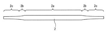
- FIG. 2 is a front view of a parison manufactured by heating and stretching the parison tube shown in FIG.
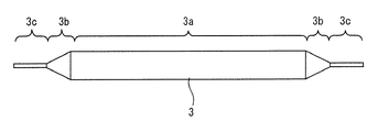
- FIG. 3 is a front view of an IABP balloon manufactured by biaxial stretch blow molding of the parison shown in FIG.
- FIG. 4 is a cross-sectional view of an IABP balloon catheter manufactured using the IABP balloon shown in FIG.
- FIG. 5 is a diagram showing a process for manufacturing a parison according to an embodiment of the present invention.
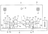
- FIG. 6A is a front view illustrating a schematic configuration of a parison manufacturing apparatus suitable for performing the parison manufacturing process illustrated in FIG. 5.
- FIG. 6A is a front view illustrating a schematic configuration of a parison manufacturing apparatus suitable for performing the parison manufacturing process illustrated in FIG. 5.
- FIG. 6A is a front view illustrating a schematic configuration of
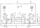
- FIG. 6B is a front view showing the parison manufacturing apparatus shown in FIG. 6A during heating and stretching.
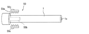
- FIG. 7A is a diagram illustrating a configuration of a chuck mechanism that configures the parison manufacturing apparatus illustrated in FIG. 6A.
- FIG. 7B is a diagram showing a state in the middle of fixing one end of the parison tube to the chuck mechanism shown in FIG. 7A.
- FIG. 7C is a diagram showing a state where one end of the parison tube is fixed to the chuck mechanism shown in FIG. 7A.
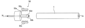
- FIG. 7D is a view showing a modification of the chuck mechanism shown in FIG. 7A.
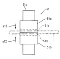
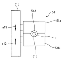
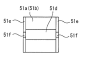
- FIG. 8A is a front view showing a configuration in a state where heating blocks of a heating mold constituting the parison manufacturing apparatus shown in FIG. 6A are separated.
- FIG. 8B is a side view of the heating mold shown in FIG. 8A.
- FIG. 8C is a bottom view of the heating block above the heating mold shown in FIG. 8A or a plan view of the lower heating block.
- FIG. 8D is a front view showing a state in which the heating block of the heating mold shown in FIG. 8A is brought into contact.
- FIG. 8E is a side view of the heating mold shown in FIG. 8D.
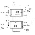
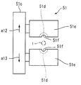
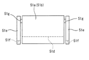
- FIG. 9A is a front view showing a configuration in a state where heating blocks showing an improved example of the heating mold shown in FIG. 8A are separated.
- FIG. 9A is a front view showing a configuration in a state where heating blocks showing an improved example of the heating mold shown in FIG. 8A are separated.
- FIG. 9B is a side view of the heating mold shown in FIG. 9A.
- FIG. 9C is a bottom view of the heating block above the heating mold shown in FIG. 9A or a plan view of the lower heating block.
- FIG. 9D is a front view showing a state in which the heating block of the heating mold shown in FIG. 9A is brought into contact.
- FIG. 9E is a side view of the heating mold shown in FIG. 9D.
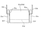
- 10A is a front view of a heating block showing an improved example of the heating mold shown in FIG. 9A.
- FIG. 10B is a front view of a heating block showing an improved example of the heating mold shown in FIG. 10A.
- FIG. 11 is a block diagram showing a configuration of a control system of the parison manufacturing apparatus shown in FIG. 6A.
- FIG. 12 is an enlarged view showing a main part of a parison for explaining an embodiment of the present invention.
- the parison tube 1 as a base material for manufacturing the parison according to the present embodiment will be described.
- the parison tube 1 is a straight tube having a diameter that is substantially constant in the axial direction from one end to the other end.
- thermoplastic resin As the material of the tube 1 for parison, a thermoplastic resin is used, and it is preferable that it is a material excellent in the bending fatigue resistance of the IABP balloon finally produced using this, for example, polyurethane, polyethylene, polyamide Polyamide elastomers, polyesters, and the like can be used, and those made of polyurethane are particularly preferable because they have a high ability to inhibit thrombus generation and high wear resistance.
- the parison tube 1 has an axial dimension of about 50 to 400 mm, an outer diameter of about ⁇ 1 to 8 mm, and a wall thickness of about 0.1 to 1.0 mm.
- the parison (balloon parison) 2 is manufactured by heating and stretching the vicinity of both ends of the above-described parison tube as a base material, and the diameter thereof is substantially constant in the axial direction. It is a double-end stretched tube in which stretched portions (stretch portions) are disposed at both ends of a large diameter straight body portion (unstretched portion) 2a. The extending portions at both ends respectively have a transition portion 2b whose diameter gradually decreases and a small-diameter straight body portion 2c whose diameter hardly changes.
- the axial dimension of the large diameter straight body 2a of the parison 2 is about 20 to 200 mm, and the axial dimension of the transition part 2b is about 2 to 50 mm.
- the outer diameter of the large diameter straight body portion 2a is about the same as the outer diameter of the parison tube 1, and the outer diameter of the small diameter straight body portion 2c is about ⁇ 0.2 to 3.0 mm.
- the balloon (IABP balloon) 3 manufactured using the above-described parison 2 gradually increases in diameter at both ends of the straight body portion 3a whose diameter is substantially constant in the axial direction.
- a cone portion (shoulder portion) 3b that decreases to a minimum and a neck portion 3c having a diameter that is substantially constant in the axial direction and smaller than that of the straight body portion 3a are arranged.
- the balloon 3 is manufactured by biaxial stretch blow molding.
- the straight barrel portion 3a of the balloon 3 is in the large diameter straight barrel portion 2a of the parison 2
- the cone portion 3b of the balloon 3 is in the transition portion 2b of the parison 2
- the neck portion 3c of the balloon 3 is in the small diameter straight barrel portion 2c of the parison 2. It roughly corresponds.
- IABP balloon catheter 4 as a final product manufactured using the above-described balloon 3 is configured as shown in FIG.
- the balloon 3 of the IABP balloon catheter 4 expands and contracts in accordance with the heart beat.
- the balloon 3 is formed of a cylindrical balloon film having a film thickness of about 20 to 200 ⁇ m.
- the shape of the balloon membrane in the expanded state is a cylindrical shape, but is not limited thereto, and may be a polygonal cylindrical shape.
- the outer diameter and length of the balloon 3 for IABP are set according to the inner volume of the balloon 3, which has a great influence on the assist effect of the cardiac function, the inner diameter of the arterial blood vessel, and the like.
- the balloon 3 usually has an inner volume of 5 to 50 cc, an outer diameter when expanded of 8 to 20 mm, and a length of 80 to 270 mm.
- the distal end of the balloon 3 is attached to the outer periphery of the distal end of the inner tube 42 through a short tube 41 or directly by heat fusion or adhesion.
- the proximal end of the balloon 3 is joined to the distal end of the catheter tube 44 via a contrast marker 43 made of a metal tube or the like or directly.
- a contrast marker 43 made of a metal tube or the like or directly.
- the pressure fluid is introduced into or extracted from the balloon 3, and the balloon 3 is expanded or contracted.
- the balloon 3 and the catheter tube 44 are joined by heat fusion or adhesion with an adhesive such as an ultraviolet curable resin.
- the distal end of the inner tube 42 projects farther from the distal end of the catheter tube 44.
- the inner tube 42 is inserted in the balloon 3 and the catheter tube 44 in the axial direction.
- the proximal end of the inner tube 42 is communicated with the second port 46 of the branch portion 45.
- a second lumen that does not communicate with the first lumen formed inside the balloon 3 and the catheter tube 44 is formed inside the inner tube 42.
- the second lumen of the inner tube 42 located in the balloon 3 is also used as a guide wire insertion lumen for conveniently inserting the balloon 3 into the artery.
- the balloon catheter 4 When the balloon catheter 4 is inserted into a body cavity such as a blood vessel, the balloon 3 is folded and wound around the outer periphery of the inner tube 42.
- the inner tube 42 is made of the same material as the catheter tube 44, for example.
- the inner diameter of the inner tube 42 may be any diameter that allows the guide wire to be inserted, and is, for example, 0.15 to 1.5 mm, preferably 0.5 to 1 mm.
- the wall thickness of the inner tube 42 is preferably 0.1 to 0.4 mm.
- the total length of the inner tube 42 is determined according to the axial length of the balloon catheter 4 inserted into the blood vessel and is not particularly limited, but is, for example, about 500 to 1200 mm, preferably about 700 to 1000 mm.
- the catheter tube 44 is preferably made of a material having a certain degree of flexibility.
- the inner diameter of the catheter tube 44 is preferably 1.5 to 4.0 mm, and the wall thickness of the catheter tube 44 is preferably 0.05 to 0.4 mm.
- the length of the catheter tube 44 is preferably about 300 to 800 mm.
- the branch end 45 installed outside the patient's body is connected to the proximal end of the catheter tube 44.
- the branch portion 45 is formed separately from the catheter tube 44 and is fixed by means such as heat fusion or adhesion.
- the branch 45 includes a first port 48 for introducing or derivatizing pressure fluid to and from the first lumen in the catheter tube 44 and the balloon 3, and a second port 46 communicating with the second lumen of the inner tube 42. Is formed.
- the first port 48 is connected to an unillustrated expansion / contraction drive device, and fluid pressure is supplied by the drive device so that the balloon 3 expands or contracts.
- the second port 46 is connected to a blood pressure fluctuation measuring device (not shown), and can measure a blood pressure fluctuation in the artery taken from the opening end 47 at the distal end of the balloon 3. Based on the blood pressure fluctuation measured by the blood pressure fluctuation measuring device, the driving device is controlled according to the heartbeat, and the balloon 3 is expanded and contracted in a short cycle of 0.4 to 1 second. .
- both ends of the unstretched straight tubular parison tube 1 are fixed (supported) in a substantially horizontal state, and as shown in FIG.
- a heating mold 51 is disposed in the vicinity.
- a heating process is performed in which the corresponding portion is heated by the heating mold 51 while rotating the parison tube 1 around its axis.
- the heating mold 51 is not particularly limited, and a non-contact type having a substantially cylindrical heating space (heating surface) having a larger diameter than the parison tube 1 can be used.
- the heating surface of the heating mold 51 has a temperature distribution, the outer periphery of the corresponding part of the parison tube 1 (the part heated by the heating mold 51). Even when the distance between the heating die 1 and the heating surface of the heating mold 1 is not constant, the temperature distribution in the circumferential direction of the corresponding portion of the parison tube 1 can be made more uniform.
- the heating temperature in the heating step is about 180 to 200 ° C., for example, when polyurethane is used as the base material of the parison tube 1, and the heating time is about 20 to 150 seconds.
- the rotation speed of the parison tube 1 around its axis is about 10 to 150 rpm.
- the heating range (a dimension in the axial direction of the heating surface) b1 by the heating mold 51 is set to about 5 to 100 mm so that the portion to be the straight body portion (large diameter straight body portion 2a) of the parison 2 is not heated as much as possible. It is desirable to heat locally.
- the parison tube 1 may be rotated around its axis as indicated by an arrow a1 in FIG.
- the parison tube 1 may be rotated around its axis as indicated by an arrow a1 in FIG.
- the cooling step may be natural cooling in a state where heating by the heating mold 51 is stopped or the heating mold 51 and the parison tube 1 are separated from each other, or cooling inside or outside the parison tube 1.
- Forcible cooling may be performed by blowing a gas.
- the cooling time is about 30 to 300 seconds when the temperature in the housing is 22 to 35 ° C.
- the heating mold 51 is disposed in the vicinity of the other end of the ends of the parison tube 1. Thereafter, as shown by an arrow a1 in the figure, a heating process is performed in which the corresponding portion is heated by the heating mold 51 while rotating the parison tube 1 around its axis.
- the heating mold 51 the same one as used in FIG. 5A may be used, or another one may be used. Heating conditions, rotation conditions, and the like are the same as those at one end shown in FIG.
- parison tube 1 may be rotated around its axis as shown by an arrow a1 in FIG. It is the same as the one end side shown in B).
- a cooling process is performed to fix the shape of the heated and stretched portion of the parison tube 1.
- the cooling method and cooling conditions are the same as those on the one end side shown in FIG.
- the parison manufacturing apparatus 5 includes a pair of chuck mechanisms (fixing mechanisms) 50 and 50, a pair of heating dies 51 and 51, a pair of rotating mechanisms 52 and 52, and a pair of stretching mechanisms 53 and 53.
- the parison manufacturing apparatus 5 includes a tension detection sensor (tension detection means) 54, a support base 55, a casing 56, a pair of fans (air conditioning means) 57 and 57, and a temperature detection sensor (air conditioning means) 58 in the casing. And a control device 59 and the like.
- the pair of chuck mechanisms 50 and 50 are means for supporting and fixing both ends of the parison tube 1 so as to be releasable in a state in which the parison tube 1 extends substantially horizontally. Since the chuck mechanisms 50 are substantially the same except that they are arranged symmetrically, only one chuck mechanism 50 (left side in FIG. 6A) will be described.
- the chuck mechanism 50 includes a substantially cylindrical positioning member having a positioning contact surface (contact portion) 50a, a substantially cylindrical pin member (pin portion) 50b, and a pair of pairs.
- a chuck member (chuck part) 50c is roughly provided.
- a pin member 50b is erected on the contact surface 50a of the positioning member so as to be substantially perpendicular to the corresponding contact surface 50a and substantially coaxial with the positioning member.
- the pin member 50b is a member that is inserted into the lumen 1a at the end of the parison tube 1, and is slightly larger in diameter as long as it is substantially equal to the inner diameter of the lumen 1a of the parison tube 1 or does not hinder insertion. Is formed.
- the distal end portion of the pin member 50b is tapered or rounded at a portion on the distal end side so that the insertion into the lumen 1a of the parison tube 1 can be performed smoothly. It is preferable to have a tinged shape.
- the abutting surface 50a of the positioning member is a surface with which the end surface of the parison tube 1 inserted into the inner cavity 1a of the pin member 50b abuts, and a stretching mechanism 53 described later is at a predetermined initial position.
- the end surface of the parison tube 1 is brought into contact with the corresponding contact surface 50a, whereby the parison tube 1 can be positioned in the extending direction (left-right direction in FIG. 6A). ing.
- the chuck members 50c and 50c are portions in which the pin member 50b is inserted into the inner lumen 1a of the end portion thereof, and the pin member 50b of the parison tube 1 in which the end surface thereof is in contact with the contact surface 50a of the positioning member. It is a member for fixing the end part of the tube 1 for parison by being pressed and clamped from the outside.
- the chuck members 50c, 50c have a plurality of claw portions that are erected on the opposing portions in order to securely fix the parison tube 1. Further, in the present embodiment, the chuck members 50c and 50c are arranged at positions facing each other by 180 degrees, and although not illustrated, they are supported so as to be symmetrically close to and separated from each other, such as an air cylinder or the like. These driving means are configured to be close to or away from each other. The operation or stop of the chuck mechanisms 50, 50 (operation or stop of the driving means) is controlled by a control device 59, which will be described later, in accordance with an operator instruction.
- the operator places one end portion of the parison tube 1 in the vicinity of one chuck member 50c, and as shown in FIG. 7B, the operator inserts a pin member into the lumen 1a on one end side of the parison tube 1.
- 50b is inserted, and the one end surface of the parison tube 1 is brought into contact with the contact surface 50a of the positioning member.
- one end of the parison tube 1 can be fixed as shown in FIG. 7C.
- the parison tube 1 extends between the pair of chuck mechanisms 50 and 50 in a substantially horizontal direction and is fixedly disposed. be able to.
- the parison tube 1 Since the parison tube 1 is sandwiched between the pin member 50b inserted into the lumen 1a and the chuck members 50c and 50c having a plurality of claws pressed against the pin member 50b, the lumen 1a of the parison tube 1 is crushed. Is difficult to occur, and it is possible to realize a strong fixation. For this reason, even when a high tensile load is applied, it is possible to withstand this. In addition, since the parison tube 1 can be accurately positioned, variation in quality between lots can be reduced.
- the number of chuck members 50c is two in the present embodiment, the number of chuck members 50c may be three or more, and they may be arranged radially at equal angular intervals.
- a gas passage 50d opened at the tip of the pin member 50b is formed, and nitrogen is introduced into the lumen 1a of the parison tube 1 through the gas passage 50d. It is preferable that an inert gas such as a gas can be supplied so as to suppress oxidation accompanying heating inside the parison tube 1.
- the chuck mechanisms 50 and 50 are supported and fixed to the rotation mechanisms 52 and 52, respectively, and the rotation mechanisms 52 and 52 are supported and fixed to the stretching mechanisms 53 and 53, respectively.
- the rotation mechanisms 52 and 52 are means for rotating the chuck mechanisms 50 and 50 so that the parison tube 1 supported and fixed therebetween rotates around its axis (see arrow a14). Since the rotation mechanisms 52 and 52 are substantially the same except that they are arranged symmetrically, only one rotation mechanism 52 (left side in FIG. 6A) will be described.
- the rotation mechanism 52 includes a disk-shaped rotation plate, a support member that rotatably supports the rotation plate, a rotation drive mechanism that rotates the rotation plate, and the like.
- the rotary plate is supported and fixed so that the positioning members of the chuck mechanism 50 described above are substantially coaxial with each other, and the support member is supported and fixed to the stretching mechanism 53.
- the rotational drive mechanism includes a drive motor (servo motor or the like) and a power transmission mechanism (timing belt, pulley, gear, or the like).
- the rotation drive mechanism is controlled by a control device 59, which will be described later, for its operation, stop, rotation direction, rotation speed, and the like.
- the rotation speed of the rotation mechanism 52 can be arbitrarily set in the range of about 0 to 150 rpm.
- both By operating the rotation mechanisms 52 and 52 in a state where both ends of the parison tube 1 are fixed to the chuck mechanisms 50 and 50, both can rotate synchronously so that the parison tube 1 can be rotated at a desired rotation speed. It has become.
- the stretching mechanisms 53 and 53 are means for applying tension to the parison tube 1 having both ends fixed to the chuck mechanisms 50 and 50 by separating one of the pair of chuck mechanisms 50 and 50 from the other. . Since the extending mechanisms 53 and 53 are substantially the same except that they are arranged symmetrically, only one extending mechanism 53 (left side in FIG. 6A) will be described.
- the stretching mechanisms 53 and 53 are mechanisms that urge one of the pair of fixing mechanisms 50 and 50 away from the other to stretch the parison tube 1 and are not shown in detail.
- the movable member 53a is configured to include a movable member 53a and a linear drive mechanism 53b that linearly moves the movable member 53a while supporting the movable member 53a so as to be movable (slidable) in the left-right direction (see arrow a16). ing.
- the support member of the rotation mechanism 52 described above is supported and fixed to the movable member 53a, and the linear drive mechanism 53b of the stretching mechanism 53 is supported and fixed to the support base 55.
- the linear drive mechanism 53b includes a drive motor (such as a servo motor) and a ball screw mechanism that converts the rotational motion of the drive motor into linear motion.
- the linear drive mechanism 53b is not limited to such a configuration, and may be a rack and pinion mechanism, a linear motor, or the like.
- the linear drive mechanism 53b is controlled in its operation, stop, moving speed, moving direction, and the like by a control device 59 described later.
- both ends of the parison tube 1 are fixed to the chuck mechanisms 50 and 50, and the stretching mechanisms 53 and 53 are operated, whereby the movable members 53a and 53a are moved. Both move synchronously (or try to move) in directions away from each other, and a desired tension can be applied to the parison tube 1.
- Each stretching mechanism 53, 53 has a tension detection sensor (tension detection means) 54 for detecting the tension generated in the parison tube 1.
- a load cell can be used as the tension detection sensor 54.
- a power transmission member 53c is arranged in parallel to be separated from the movable member 53a in the moving direction, and a coil spring (not shown) and a tension detection sensor (load cell) are arranged between the movable member 53a and the power transmission member 53c. ) 54 and the driving force of the linear drive mechanism 53b is transmitted to the movable member 53a via the power transmission member 53c.
- the detection value of the tension detection sensor 54 is input to the control device 59, and the thrust by the linear drive mechanism 53b is controlled by the control device 59 so that an appropriate preset tension is applied.
- the heating dies 51, 51 have a part on one end side (a part to be an extension part) and a part on the other end side (an extension part) This is a means for heating the portion to be formed in a non-contact manner.
- the heating dies 51, 51 are disposed between the chuck mechanisms 50, 50 and spaced apart from each other in the left-right direction (the direction in which the parison tube 1 extends) in FIG. Since these heating molds 51 and 51 have substantially the same configuration, only one heating mold 51 (left side in FIG. 6A) will be described.
- the heating mold 51 has a pair of upper and lower heating blocks 51a and 51b each made of a metal material such as beryllium copper.
- the heating blocks 51a and 51b are moved up and down synchronously so as to be close to and away from each other in the vertical direction (see arrow a11 in FIG. 6A) by the lifting mechanism 51c.
- the elevating mechanism 51c includes a slide mechanism that holds the heating blocks 51a and 51b so that the heating blocks 51a and 51b can be slid upward and downward, a servo motor for moving the heating blocks 51a and 51b up and down, a ball screw, and the like. Drive mechanism.
- the heating blocks 51a and 51b are configured so that both move symmetrically and are separated from each other, but one (for example, the lower heating block 51b) is fixed, Only the other (for example, the upper heating block 51a) may be configured to move up and down, or vice versa.
- a substantially semi-cylindrical inner wall surface (heating surface 51d) is formed on the lower surface of the upper heating block 51a and the upper surface of the lower heating block 51b, and the lower surface of the upper heating block 51a and the lower heating block 51b When the upper surface comes into contact, the semi-cylindrical heating surfaces 51d and 51d cause the left and right direction (the direction in which the parison tube 1 whose both ends are supported and fixed to the chuck mechanisms 50 and 50 extend). , The central axis extends, and a substantially cylindrical heating space opened at both ends thereof is defined.
- each heating block 51a, 51b incorporates a heater that generates heat when energized and a mold temperature detection sensor (for example, a thermocouple) that detects the temperature of the heating block 51a, 51b.
- the control device 59 controls energization to the heater based on the detection value by the mold temperature detection sensor (see reference numeral 59c in FIG. 11), and is a substantially circle defined by the heating surfaces 51d and 51d of the heating blocks 51a and 51b.
- the columnar heating space is heated so as to have an appropriate temperature.
- the number of heaters and mold temperature detection sensors provided in each of the heating blocks 51a and 51b may be single or plural, but a plurality is more preferable because the temperature distribution on the heating surfaces 51d and 51d can be made more uniform. .
- the inner diameter of the substantially cylindrical heating space defined by the heating surfaces 51d and 51d of the heating blocks 51a and 51b is separated from the outer periphery of the parison tube 1 disposed through the inside by a predetermined dimension.
- the diameter is set larger than the outer diameter of the parison tube 1 so that it can be heated without contact.
- the inner diameter of the substantially cylindrical heating space defined by the heating surfaces 51d and 51d of the heating blocks 51a and 51b is set to about 2 to 12 mm.
- the upper heating block 51a is set upward (see arrow a12) and the lower heating block is set. 51b is moved downward (see arrow a13) to be spaced apart from each other and open.
- the upper heating block 51a is downward (see arrow a13) and the lower heating block 51b is upward (arrow a12).
- the lower surface of the upper heating block 51a and the upper surface of the lower heating block 51b are brought into contact with each other to be in a closed state.
- the upper heating block 51a is moved upward (see arrow a12) and the lower heating block 51b is moved downward (see This can be done by moving to the arrow a13) and making it open.
- FIG. 9A to FIG. 9E are diagrams showing an example in which the heating mold 51 is improved.
- positioning plates 51e and 51e each having a substantially rectangular thin plate shape are attached to both side surfaces where openings of a substantially cylindrical heating space defined by the heating surfaces 51d and 51d of the heating blocks 51a and 51b are present. It has been.
- the positioning plates 51e and 51e are substantially rectangular so as to cover the entire corresponding side surfaces of the heating blocks 51a and 51b.
- the shape need not be rectangular as long as the parison tube 1 can be supported in a predetermined state.
- These positioning plates 51e position and support the parison tube 1 so that its axis is substantially coaxial with the axis of the substantially cylindrical heating space defined by the heating surfaces 51d and 51d of the heating blocks 51a and 51b. It has a substantially semicircular cutout 51f that can contact the outer periphery of the parison tube 1.
- the inner diameter of the notch 51f is set to be slightly larger than the outer diameter of the parison tube 1.
- the cutout 51f may have an arc shape that is less than a semicircle or other shapes as long as it can support the parison tube 1 in a predetermined state.
- the positioning plates 51e and 51e attached to both side surfaces of the upper heating block 51a and the positioning plates 51e and 51e attached to both side surfaces of the lower heating block 51b have their sides (surfaces) having the notch portions 51f up and down. It arrange
- the side having the notch 51f of the positioning plate 51e of the upper heating block 51a and the side having the notch 51f of the positioning plate 51e of the lower heating block 51b Are in contact with each other or in a state of being slightly spaced apart from each other.
- the upper heating block 51a is moved upward and the lower heating block 51b is moved downward so that they are separated from each other.
- the plate 51d is in an open state as shown in FIGS. 9A and 9B. From this state, in order to heat the vicinity of both ends of the parison tube 1, the upper heating block 51a is moved downward and the lower heating block 51b is moved upward, and the lower surface of the upper heating block 51a and the lower When the upper surface of the heating block 51b is in contact with each other, the positioning plate 51d is in a closed state as shown in FIGS. 9D and 9E.
- the parison tube 1 is positioned at corresponding positions on both sides of the heating blocks 51a and 51b by a pair of notches 51f and 51f on the left and right, respectively. Each is positioned and supported. Thereby, the tube 1 for parison can be positioned so that the axial center may become substantially coaxial with the axial center of the substantially cylindrical heating space defined by the heating surfaces 51d and 51d of the heating blocks 51a and 51b. .
- the heating surfaces 51d and 51d of the heating blocks 51a and 51b and the parison tube 1 should be stretched during heating. Since the distance from the outer periphery of the part is substantially equal in the circumferential direction, even when the parison tube 1 is not rotated around its axis during heating, the occurrence of uneven heating can be suppressed.
- the tube 1 for parison 1 when the tube 1 for parison 1 is rotated at the time of a heating, there exists a possibility that the part (supported part) with which the notch parts 51f and 51f of the outer periphery of the tube 1 for parison contact
- abut may be damaged.
- the diameter of the notch 51f is set to be large, and a plurality of short wires having elasticity are radially arranged on the inner surface thereof and brushes are arranged radially and arranged in a plurality of rows. It is good to comprise so that positioning can be performed, preventing sticking. In this way, by combining the rotation of the parison tube 1 and the positioning, it is possible to synergistically suppress the occurrence of heating unevenness in the circumferential direction of the parison tube 1.
- the material of the positioning plate 51e is not particularly limited as long as it is suitable for positioning of the parison tube 1, but preferably has a heat insulating property.
- the positioning plate 51e as a heat insulating plate, it is possible to prevent the temperature in the housing 56 from rising due to heat from the side surfaces of the heating blocks 51a and 51b and heat from the opening of the heating space. be able to.
- As the positioning plate (heat insulating plate) 51e a polyimide resin plate, a glass epoxy laminated plate, a glass fiber laminated plate, or the like can be adopted.
- the thickness of the positioning plate (heat insulating plate) 51e is about 1 to 40 mm.
- the positioning plate (heat insulating plate) 51e can be attached with a spacer member 51g interposed slightly spaced from the side surfaces of the heating blocks 51a and 51b. In this way, by attaching them apart from each other, an air layer is disposed between them, and the heat insulation effect can be improved.
- gas passages 51h and 51h for supplying gas are provided in the space between the heating blocks 51a and 51b and the positioning plate (heat insulating plate) 51e, for example, cooled. Air may be supplied to actively cool this space. By comprising in this way, the heat insulation effect can further be improved.
- the pair of stretching mechanisms 53, 53 (linear drive mechanisms 53b, 53b) and the pair of heating dies 51, 51 (elevating mechanisms 51c, 51c) holding the chuck mechanism 50 and the rotating mechanism 52 are supported by a support base.
- the entirety of these components is housed in a housing 56.
- a housing 56 As the housing 56, a frame made of a metal or the like and a transparent panel (for example, an acrylic plate) attached thereto can be used.
- the casing 56 is provided with an openable / closable door for manually fixing or removing the parison tube 1 with respect to the chuck mechanisms 50, 50, or for other maintenance. Yes.
- a plurality of intake and exhaust (exhaust in this embodiment) fans 57 and 57 and an in-casing temperature detection sensor 58 for detecting the temperature in the casing 56 are attached to the casing 56.
- the control device 59 includes input means 59a and display means 59b.
- the input means 59a includes buttons for operating or releasing the chuck mechanisms 50, 50, an emergency stop button, other buttons, a keyboard for selecting functions and inputting various setting values, and the like.
- the display means 59b includes a liquid crystal monitor and various indicators.
- the operator manually sets the unstretched parison tube 1 to the chuck mechanisms 50 and 50 at both ends thereof.
- the moving devices 53 and 53 are set to predetermined initial positions, and the heating dies 51 and 51 are in a state where the heating blocks 51a and 51b are separated (open). It has become.
- the operation buttons of the chuck mechanisms 50 and 50 are pressed to support and fix the parison tube 1.
- the operator When it is confirmed that the ends of the parison tube 1 are fixed normally, the operator performs a predetermined operation (for example, presses a start button for heating and stretching), thereby performing a series of steps for manufacturing the parison. Operation starts.
- the control device 59 automatically controls each part in accordance with a control sequence previously selected by the operator. Note that this operation may be omitted, and a series of controls including the operation of fixing both ends of the above-described parison tube 1 may be started by pressing the operation buttons of the above-described chuck mechanisms 50 and 50.
- the stretching mechanisms 53 and 53 are driven so as to be separated from each other so that both ends of the parison tube 1 are supported and fixed to the chuck mechanisms 50 and 50 in advance.
- the set tension (initial tension) is applied and the state is maintained.
- the tension generated in the parison tube 1 is detected by a tension detection sensor 54. Based on the detected value, the stretching mechanisms 53 and 53 are controlled so as to have a preset initial tension, and the initial tension is set. After reaching, the feedback control is performed so that the tension becomes constant.
- the initial tension is appropriately determined so that the slack of the parison tube 1 supported at both ends by the chuck mechanisms 50 and 50 (the difference in height between the central portion in the axial direction of the tube and the fixed portions at both ends) is within an allowable range. Set to the correct value. If the initial tension is too small, the slackness increases, and when placed in the heating space of the heating mold 51, there is a risk of contact with the inner wall surface (heating surface 51d) and melting, or uneven heating. It may be a cause. On the other hand, if the initial tension is too large, the slackness is reduced and the above problem can be solved.
- the heating portion of the parison tube 1 is unnecessarily stretched during the heating by the heating mold 51 and is manufactured.
- the unevenness of the transition part 2b of the parison 2 may not be uniform (the inclination becomes two steps), which may cause stretching unevenness.
- the initial tension is set to an appropriate value that both of these allow.
- the initial tension can be about 1 to 10N.
- the tension generated in the parison tube 1 can be detected in real time by the tension detection sensor 54, the initial tension can be accurately maintained constant at a desired value, and the fluctuation of the initial tension can be maintained. It is possible to reduce the occurrence of stretching unevenness.
- the elevating mechanisms 51c and 51c of the heating dies 51 and 51 are operated, the upper heating block 51a is lowered (see arrow a12 in the figure), and the lower heating block 51b is raised. Then (see arrow a13 in the figure), the portions to be stretched in the vicinity of both ends of the parison tube 1 are defined by the heating surfaces 51d and 51d of the heating blocks 51a and 51b. It arrange
- energization is performed to the heaters of the heating molds 51 and 51, and heat generation is started.
- the energization of the heaters of the heating molds 51 and 51 may be performed before the heating blocks 51a and 51b are closed.
- the temperatures of the heating molds 51 and 51 are detected by a mold temperature detection sensor 59c, and energization of the heater is controlled so as to be a predetermined temperature set in advance.
- Simultaneously or before and after the operation of the heating dies 51, 51, synchronous rotation by the rotation mechanisms 52, 52 is started (see arrow a15), and the rotation is maintained at a predetermined rotation speed (rpm). Note that the rotation direction of the rotation mechanisms 52, 52 may be opposite to the arrow a15.
- the movement of the linear drive mechanisms 53b, 53b of the stretching mechanisms 53, 53 is stopped, and this state is maintained for a preset predetermined time.
- the parison tube 1 is cooled. Thereby, the shape of the tube 1 for parison by which the vicinity part of the both ends was extended is fixed. The rotation may be continued or re-executed during cooling. If cooling for a predetermined time has been performed, the operator is notified that a series of operations has been completed, and this sequence is completed.
- the end notification can be displayed on an indicator or the like of the display means 59b, or can be made with a buzzer or the like.
- the operator depresses the release buttons of the chuck mechanisms 50 and 50 to release the fixing of both ends of the parison tube 1 in which the portions near the both ends are extended. Remove this at work.
- the temperature in the casing 56 is detected by the temperature detection sensor 58 in the casing, and the fans 57 and 57 are activated or stopped based on the detected value, whereby the casing 56 is detected.
- the temperature in the body 56 is controlled to be constant.
- the releasing operation of the chuck mechanisms 50, 50 may be omitted, and this operation may be included in a series of sequences.
- the parison 2 as a completed body shown in FIG. 2 is obtained by manually cutting an appropriate portion of the stretched portion of the tube 1 for parison in which the vicinity of both ends is stretched and cutting off both ends. Obtainable.
- a straight tube made of polyurethane is cut at 250 mm (a dimension between the contact surfaces 50a and 50a of the chuck mechanisms 50 and 50 when the stretching mechanisms 53 and 53 are set to the initial positions).
- a plurality of parison tubes 1 were manufactured.
- the outer diameter of the tube was 4 mm and the wall thickness was 0.5 mm.
- the parison tube 1 was set in the parison manufacturing apparatus 5 shown in FIG. 6A, the rotation mechanisms 52 and 52 were operated, and the parison tube 1 was heated while rotating around its axis.
- the rotation speed was 30 rpm
- the mold temperature was 190 ° C.
- the heating time was 55 seconds.
- the stretching speed was 140 mm / second
- the stretching length was 60 mm.
- the applied tension (initial tension) was 5 N, and the moving speed was 25 mm / second.
- the cooling time was 60 seconds.
- casing 56 during manufacture was controlled to 30 degreeC. Five test pieces were manufactured under the same conditions.
- the average value of the angle difference is 1.63 °
- the average value of the angle difference is 3 It was .54 °, and it was confirmed that the example with rotation at the time of heating had a smaller average value of the angle difference and was superior to the comparative example.
- Extension mechanism 53a Movable member 53b ... Linear drive mechanism 54 .
- Tension detection sensor (tension detection means) 55 ... Support stand 56 ... Case 57 ... Fan (air conditioning means) 58 ... In-case temperature detection sensor (air conditioning means) 59 ... Control device 59a ... Input means 59b ... Output means 59c ... Mold temperature detection sensor
Landscapes
- Health & Medical Sciences (AREA)
- Life Sciences & Earth Sciences (AREA)
- Heart & Thoracic Surgery (AREA)
- Engineering & Computer Science (AREA)
- Biophysics (AREA)
- Pulmonology (AREA)
- Child & Adolescent Psychology (AREA)
- Anesthesiology (AREA)
- Biomedical Technology (AREA)
- Hematology (AREA)
- Animal Behavior & Ethology (AREA)
- General Health & Medical Sciences (AREA)
- Public Health (AREA)
- Veterinary Medicine (AREA)
- Media Introduction/Drainage Providing Device (AREA)
Abstract
【課題】均一な膜厚分布を有するバルーンを製造すること。 【解決手段】バルーンカテーテルに用いられるバルーンを製造するための、直胴部の両端に延伸部を有するパリソンの製造方法である。直管状のパリソン用チューブ1をその軸心周りに回転させつつ(矢印a1)、該パリソン用チューブ1の一部を加熱金型51で加熱する加熱工程(A)と、パリソン用チューブ1に張力を印加して(矢印a2)、パリソン用チューブ1の加熱工程で加熱された部分を延伸する延伸工程(B)と、を含む。
Description
本発明は、IABP(大動脈内バルーンポンピング)等に用いられるバルーンカテーテルに具備されるバルーンを製造するためのパリソン製造方法および該製造方法を実施するのに好適なパリソン製造装置に関する。
心機能低下時の治療として、大動脈内にバルーンカテーテルを挿入し、心臓の拍動に合わせてバルーンを拡張および収縮させて心機能の補助を行うIABP(大動脈内バルーンポンピング)が行われている。IABPに用いられるIABP用バルーンカテーテルは、大腿動脈等から挿入され、バルーンを胸部下行大動脈に留置した状態で使用される。
このようなIABP用バルーンカテーテルに用いられるバルーンは、直胴部の両端にそれぞれ先細テーパ状に形成されたコーン部(ショルダー部)が配置され、各コーン部の先端に直胴状のネック部がそれぞれ配置された形状を有する。バルーンは、ネック部がカテーテルシースの外面に取り付けられることにより、装着される。
このようなバルーンは、押出成形により管状に形成されたパリソン(チューブ)を二軸延伸ブロー成形することにより製造される。そのためのパリソンの製造技術としては、IABP用バルーンカテーテルではなく、PTCA(脈管成形術)用バルーンカテーテルに関するものではあるが、特許文献1に記載のものが知られている。
この技術では、バルーンの膜厚の均一性を向上させるため、ブロー成形に用いるパリソンとして、その両端部が直胴部よりも細径化された両端異径(細径)チューブが用いられている。この両端異径チューブは、特許文献1では、押出成形する際に、押出機による押出条件や引取機による引取条件等を適宜に変更制御して、細い部分と太い部分を交互に形成することにより、製造されている。
このような両端異形チューブの他の製法としては、押出成形により直管状に形成されたチューブの両端の近傍部分をそれぞれ加熱・延伸するものが実用されている。この方法では、直管状に形成されたチューブの一端側の一部を加熱金型で加熱し、該チューブの両端に張力を印加して該一端側の加熱部分を延伸した後に冷却し、次いで、該チューブの他端側の一部を同様に加熱金型で加熱し、該チューブの両端に張力を印加して該他端側の加熱部分を延伸した後に冷却している。
加熱金型としては、その内壁面が加熱面となる略円柱状の加熱空間を有し、この中に非接触状態でチューブを挿通して周囲から加熱するものが用いられている。しかしながら、加熱空間の加熱面は必ずしも一様な温度分布とはならない場合があり、そのためチューブの周方向における温度分布が均一とはならない場合があった。これにより、高温部における延伸率が低温部における延伸率よりも大きくなって肉厚が不均一となり、かかるパリソンを用いてブロー成形してバルーンを製造すると、バルーンのコーン部において、周方向に不均一な膜厚分布(膜厚ムラ)が生じる場合があるという問題があった。
本発明は、このような実状に鑑みてなされ、その目的は、均一な膜厚分布を有するバルーンを製造することができるパリソンの製造方法および装置を提供することである。
本発明の第1の観点に係るパリソン製造方法は、
バルーンカテーテルに用いられるバルーンを製造するための、直胴部の両端にそれぞれ延伸部を有するパリソンの製造方法であって、
直管状のパリソン用チューブをその軸心周りに回転させつつ、該パリソン用チューブの一部を加熱する加熱工程と、
前記パリソン用チューブに張力を印加して、前記パリソン用チューブの前記加熱工程で加熱された部分を延伸する延伸工程と、を含む。
バルーンカテーテルに用いられるバルーンを製造するための、直胴部の両端にそれぞれ延伸部を有するパリソンの製造方法であって、
直管状のパリソン用チューブをその軸心周りに回転させつつ、該パリソン用チューブの一部を加熱する加熱工程と、
前記パリソン用チューブに張力を印加して、前記パリソン用チューブの前記加熱工程で加熱された部分を延伸する延伸工程と、を含む。
本発明の第1の観点に係るパリソン製造方法では、パリソン用チューブを回転させつつ、加熱するようにしたので、パリソン用チューブの周方向における温度分布がより均一となり、延伸時において、パリソン用チューブの周方向における延伸率がより均一となる。したがって、この方法で製造されたパリソンを用いてブロー成形してバルーンを製造すると、バルーンのコーン部の周方向における膜厚分布がより均一なバルーンを得ることができる。
本発明の第1の観点に係るパリソン製造方法において、前記延伸工程を、前記パリソン用チューブをその軸心周りに回転させつつ行うようにできる。延伸時にもパリソン用チューブを回転させることで、延伸中における重力の作用によるパリソン用チューブの変形を抑制することができ、周方向における膜厚分布をさらに均一化することができる。
本発明の第1の観点に係るパリソン製造方法において、前記延伸工程後の前記パリソン用チューブをその軸心周りに回転させつつ冷却する冷却工程をさらに含むことができる。冷却時にもパリソン用チューブを回転させることで、冷却中における重力の作用によるパリソン用チューブの変形を抑制することができ、周方向における膜厚分布をさらに均一化することができる。
本発明の第2の観点に係るパリソン製造装置は、
バルーンカテーテルに用いられるバルーンを製造するための、直胴部の両端にそれぞれ延伸部を有するパリソンの製造装置であって、
直管状のパリソン用チューブの両端をそれぞれ解除可能に固定する一対の固定機構と、
前記固定機構に固定された前記パリソン用チューブの一部を非接触で加熱する加熱金型と、
前記固定機構を、前記パリソン用チューブがその軸心周りに回転するように、回転させる回転機構と、
前記一対の固定機構の一方を他方に対して離間するように付勢して、前記パリソン用チューブを延伸させる延伸機構と、を有する。
バルーンカテーテルに用いられるバルーンを製造するための、直胴部の両端にそれぞれ延伸部を有するパリソンの製造装置であって、
直管状のパリソン用チューブの両端をそれぞれ解除可能に固定する一対の固定機構と、
前記固定機構に固定された前記パリソン用チューブの一部を非接触で加熱する加熱金型と、
前記固定機構を、前記パリソン用チューブがその軸心周りに回転するように、回転させる回転機構と、
前記一対の固定機構の一方を他方に対して離間するように付勢して、前記パリソン用チューブを延伸させる延伸機構と、を有する。
本発明の第2の観点に係るパリソン製造装置によると、本発明の第1の観点に係るパリソン製造方法を好適に実施し得るパリソン製造装置が提供される。
本発明の第2の観点に係るパリソン製造装置において、
前記加熱金型は、
前記固定機構に固定された前記パリソン用チューブが挿通配置される該パリソン用チューブよりも大径の略円柱状であって、その内面が加熱面となっている加熱空間を備える加熱ブロックと、
前記加熱ブロックの前記加熱空間の開口部が存在する側面に取り付けられ、前記パリソン用チューブを該パリソン用チューブの軸心が該加熱空間の軸心と実質的に同軸となるように、該パリソン用チューブを位置決め支持する位置決め板と、を有することができる。
前記加熱金型は、
前記固定機構に固定された前記パリソン用チューブが挿通配置される該パリソン用チューブよりも大径の略円柱状であって、その内面が加熱面となっている加熱空間を備える加熱ブロックと、
前記加熱ブロックの前記加熱空間の開口部が存在する側面に取り付けられ、前記パリソン用チューブを該パリソン用チューブの軸心が該加熱空間の軸心と実質的に同軸となるように、該パリソン用チューブを位置決め支持する位置決め板と、を有することができる。
このように位置決め板を設けることにより、加熱ブロックの加熱空間の軸心にパリソン用チューブの軸心を実質的に一致させることが可能であり、パリソン用チューブの外周と加熱空間の加熱面との間の距離が周方向においてより均等となるので、パリソン用チューブの周方向における温度分布をより均一化することができる。
本発明の第2の観点に係るパリソン製造装置において、前記位置決め板を、断熱板とすることができる。このようにパリソン用チューブを支持する位置決め板を、断熱板とすることにより、加熱空間内の熱が外に逃げることが抑制され、加熱空間内をより効率的に加熱し得るとともに、パリソン用チューブの該加熱部以外の部分の雰囲気温度の上昇を抑制し得る。
この場合において、前記断熱板は、前記加熱ブロックの前記側面から僅かに離間して取り付けることができる。このように断熱板を加熱ブロックから離間して取り付けることにより、これらの間に空気層が形成され、断熱効果をより向上することができ、パリソン用チューブの該加熱部以外の部分の雰囲気温度の上昇をさらに抑制し得る。
この場合において、前記加熱ブロックと前記断熱板との間の空間に、気体を供給するようにできる。このように気体を供給することにより、パリソン用チューブの該加熱部以外の部分の雰囲気温度の上昇をさらに抑制し得る。
本発明の第2の観点に係るパリソン製造装置において、
当該装置全体を覆う筐体と、
前記筐体内の温度を実質的に一定となるように空調する空調手段と、をさらに有することができる。
当該装置全体を覆う筐体と、
前記筐体内の温度を実質的に一定となるように空調する空調手段と、をさらに有することができる。
装置全体を筐体で覆うことにより、装置周囲の空気の流れによる影響を小さくすることができるとともに、空調手段により筐体の温度を一定に保つことができるため、パリソンの製造を継続的に繰り返し行った場合でも、パリソン用チューブの雰囲気温度がロット間で略一定となり、品質のバラツキを少なくすることが可能である。
以下、本発明の一実施形態として、IABP(大動脈内バルーンポンピング)に用いられるバルーンカテーテルに具備されるバルーンを製造する場合を例にとり、図面を参照して説明する。
まず、本実施形態に係るパリソンを製造するための母材としてのパリソン用チューブ1について説明する。パリソン用チューブ1は、図1に示すように、その一端から他端に渡ってその径が軸方向に実質的に一定である直管状のチューブである。
パリソン用チューブ1の材料としては、熱可塑性樹脂が用いられ、これを用いて最終的に製造されるIABP用バルーンの耐屈曲疲労特性に優れた材質であることが好ましく、たとえばポリウレタン、ポリエチレン、ポリアミド、ポリアミドエラストマー、ポリエステル等を用いることができ、特にポリウレタンで形成されたものが血栓の発生抑止能が高く、耐摩耗性も高いので好適である。
パリソン用チューブ1の製造方法は特に限定されないが、押出成形により製造されたものを用いることができる。パリソン用チューブ1の軸方向の寸法は50~400mm程度であり、外径はφ1~8mm程度であり、肉厚は0.1~1.0mm程度である。
上述したパリソン用チューブを母材とし、その両端の近傍部分を加熱延伸して製造されるパリソン(バルーン用パリソン)2は、図2に示すように、その径が軸方向に実質的に一定の大径直胴部(未ストレッチ部)2aの両端に延伸部(ストレッチ部)をそれぞれ配置してなる両端延伸チューブである。両端の延伸部は、その径が徐々に減少する遷移部2bおよびその径が殆ど変化しない小径直胴部2cをそれぞれ有する。
パリソン2の大径直胴部2aの軸方向の寸法は20~200mm程度であり、遷移部2bの軸方向の寸法は2~50mm程度である。大径直胴部2aの外径は、パリソン用チューブ1の外径と同程度であり、小径直胴部2cの外径はφ0.2~3.0mm程度である。
上述したパリソン2を用いて製造されるバルーン(IABP用バルーン)3は、図3に示すように、その径が軸方向に実質的に一定の直胴部3aの両端にそれぞれ、その径が徐々に減少するコーン部(ショルダー部)3bおよびその径が軸方向に実質的に一定で直胴部3aよりも小径のネック部3cを配置して構成されている。バルーン3は、二軸延伸ブロー成形により製造される。バルーン3の直胴部3aはパリソン2の大径直胴部2aに、バルーン3のコーン部3bはパリソン2の遷移部2bに、バルーン3のネック部3cは、パリソン2の小径直胴部2cに概略対応している。
上述したバルーン3を用いて製造される最終製品としてのIABP用バルーンカテーテル4は、図4に示すように構成されている。IABP用バルーンカテーテル4のバルーン3は、心臓の拍動に合わせて拡張および収縮する。バルーン3は、膜厚約20~200μm程度の筒状のバルーン膜で構成される。本実施形態では、拡張状態のバルーン膜の形状は円筒形状であるが、これに限定されず、多角筒形状であってもよい。
IABP用のバルーン3の外径および長さは、心機能の補助効果に大きく影響するバルーン3の内容積と、動脈血管の内径等に応じて設定される。バルーン3は、通常、その内容積が5~50ccであり、拡張時の外径が8~20mmであり、長さが80~270mmである。
このバルーン3の遠位端は、短チューブ41を介してまたは直接に内管42の遠位端外周に熱融着または接着等により取り付けられている。バルーン3の近位端は、金属チューブ等からなる造影マーカ43を介してまたは直接に、カテーテル管44の遠位端に接合されている。カテーテル管44の内部に形成された第1のルーメンを通じて、圧力流体のバルーン3内に対する導入または導出が行われ、バルーン3が拡張または収縮するようになっている。バルーン3とカテーテル管44との接合は熱融着あるいは紫外線硬化樹脂等の接着剤による接着により行われる。
内管42の遠位端はカテーテル管44の遠位端より遠方へ突き出ている。内管42はバルーン3およびカテーテル管44の内部に軸方向に挿通されている。内管42の近位端は分岐部45の第2ポート46に連通されている。内管42の内部には、バルーン3の内部およびカテーテル管44内に形成された第1のルーメンとは連通しない第2のルーメンが形成されている。
バルーンカテーテル4を動脈内に挿入する際に、バルーン3内に位置する内管42の第2ルーメンはバルーン3を都合良く動脈内に差し込むためのガイドワイヤー挿通管腔としても用いられる。バルーンカテーテル4を血管等の体腔内に差し込む際には、バルーン3は内管42の外周に折り畳んで巻回される。内管42は、たとえばカテーテル管44と同様な材質で構成される。
内管42の内径は、ガイドワイヤーを挿通できる径であればよく、たとえば0.15~1.5mm、好ましくは0.5~1mmである。この内管42の肉厚は、0.1~0.4mmが好ましい。内管42の全長は、血管内に挿入されるバルーンカテーテル4の軸方向長さ等に応じて決定され、特に限定されないが、たとえば500~1200mm、好ましくは700~1000mm程度である。
カテーテル管44は、ある程度の可撓性を有する材質で構成されることが好ましい。カテーテル管44の内径は、好ましくは1.5~4.0mmであり、カテーテル管44の肉厚は、好ましくは0.05~0.4mmである。カテーテル管44の長さは、好ましくは300~800mm程度である。
カテーテル管44の近位端には患者の体外に設置される分岐部45が連結してある。分岐部45はカテーテル管44と別体に成形され、熱融着あるいは接着等の手段で固着される。分岐部45にはカテーテル管44内の第1のルーメンおよびバルーン3に対する圧力流体の導入または導出を行うための第1ポート48と、内管42の第2ルーメン内に連通する第2ポート46とが形成されている。
第1ポート48は、不図示の拡張・収縮駆動装置に接続され、この駆動装置によりバルーン3が拡張または収縮するように流体圧が供給されるようになっている。第2ポート46は、不図示の血圧変動測定装置に接続され、バルーン3の遠位端の開口端47から取り入れた動脈内の血圧の変動を測定可能になっている。この血圧変動測定装置で測定した血圧の変動に基づき、心臓の拍動に応じて、駆動装置を制御し、0.4~1秒の短周期でバルーン3を拡張および収縮させるようになっている。
次に、上述したパリソン2の製造工程について、図5を参照して説明する。まず、未延伸の直管状のパリソン用チューブ1を略水平にした状態でその両端を固定(支持)し、図5(A)に示すように、パリソン用チューブ1の両端のうちの一端側の近傍部分に、加熱金型51を配置する。次いで、同図に矢印a1で示すように、パリソン用チューブ1をその軸心周りに回転させつつ、加熱金型51により、該当部分を加熱する加熱工程を実施する。なお、加熱金型51としては、特に限定されないが、パリソン用チューブ1よりも大きい径を有する略円柱状の加熱空間(加熱面)を有する非接触タイプのものを用いることができる。
このように加熱時にその軸心周りに回転させることにより、加熱金型51の加熱面に温度分布がある場合やパリソン用チューブ1の該当部分(該加熱金型51によって加熱される部分)の外周と加熱金型1の加熱面との距離が一定でない場合であっても、パリソン用チューブ1の該当部分の周方向における温度分布をより均一に近づけることができる。
加熱工程における加熱温度は、パリソン用チューブ1の母材として、たとえばポリウレタンを用いる場合、180~200℃程度であり、加熱時間は20~150秒程度である。パリソン用チューブ1のその軸心周りの回転速度は、10~150rpm程度である。加熱金型51による加熱範囲(加熱面の軸方向の寸法)b1は、5~100mm程度として、パリソン2の直胴部(大径直胴部2a)となるべき部分については極力加熱されないように、局所的に加熱を行うことが望ましい。
次いで、図5(B)に示すように、パリソン用チューブ1の一端を他端に対して、同図中の矢印a2で示すように引っ張ることにより、パリソン用チューブ1に張力を印加して、パリソン用チューブ1の加熱工程で加熱された部分を延伸する延伸工程を実施する。延伸工程における張力は、2~20N程度であり、延伸寸法b2は、5~200mm程度である。
なお、必須ではないが、この延伸工程の実施中に、図5(B)中に矢印a1で示すように、パリソン用チューブ1をその軸心周りに回転させてもよい。延伸時にもパリソン用チューブ1をその軸心周りに回転させることで、延伸中における重力の作用によるパリソン用チューブ1の特に加熱された部分の変形を抑制することができる。また、本実施形態では、延伸工程を実施する際には、加熱金型51による加熱は停止しているものとするが、加熱を継続しながら行ってもよい。
延伸工程が終了したならば、次いで、図5(C)に示すように、パリソン用チューブ1の加熱延伸された部分の形状を定着させるため、冷却工程を実施する。冷却工程は、加熱金型51による加熱を停止した状態または加熱金型51とパリソン用チューブ1とを離間させた状態で、自然冷却してもよいし、パリソン用チューブ1の内側または外側に冷却用の気体を送風して、強制冷却するようにしてもよい。冷却時間としては、自然冷却の場合、筐体内温度が22~35℃である場合において、30~300秒程度である。
次いで、図5(D)に示すように、パリソン用チューブ1の両端のうちの他端側の近傍部分に、加熱金型51を配置する。その後、同図に矢印a1で示すように、パリソン用チューブ1をその軸心周りに回転させつつ、加熱金型51により、該当部分を加熱する加熱工程を実施する。なお、加熱金型51としては、図5(A)で用いたものと同じものを用いてもよいし、別のものを用いてもよい。加熱条件や回転条件等は図5(A)に示した一端側と同様である。
次いで、図5(E)に示すように、パリソン用チューブ1の他端を一端に対して、同図中の矢印a3で示すように引っ張ることにより、パリソン用チューブ1に張力を印加して、パリソン用チューブ1の加熱工程で加熱された部分を延伸する延伸工程を実施する。延伸条件等は、図5(B)に示した一端側と同様である。
なお、必須ではないが、この延伸工程の実施中に、図5(E)中に矢印a1で示すように、パリソン用チューブ1をその軸心周りに回転させてもよいのは、図5(B)に示した一端側と同様である。
延伸工程が終了したならば、図5(F)示すように、パリソン用チューブ1の加熱延伸された部分の形状を定着させるため、冷却工程を実施する。冷却方法や冷却条件は、図5(C)に示した一端側と同様である。
最後に、その両端の近傍部分を延伸したパリソン用チューブ1の両端の固定(支持)を解除し、延伸した部分の適宜な箇所(図5(F)中、符号c1で示した位置)で、それぞれ切断することにより、図2に示した完成体としてのパリソン(バルーン用パリソン)2を得ることができる。
次に、上述したパリソン2の製造工程を実施するための製造装置について、図6Aを参照して説明する。このパリソン製造装置5は、一対のチャック機構(固定機構)50,50、一対の加熱金型51,51、一対の回転機構52,52、および一対の延伸機構53,53を備えている。これに加えて、パリソン製造装置5は、張力検出センサ(張力検出手段)54、支持台55、筐体56、一対のファン(空調手段)57,57、筐体内温度検出センサ(空調手段)58および制御装置59等も備えている。
一対のチャック機構50,50は、パリソン用チューブ1を略水平に延在させた状態でその両端をそれぞれ解除可能に支持固定する手段である。チャック機構50,50は、対称的に配置されている以外は実質的に同じ構成であるので、一方(図6Aにおいて、左側)のチャック機構50についてのみ説明する。
チャック機構50は、図7A~図7Cに示すように、位置決め用の当接面(当接部)50aを有する略円柱状の位置決め部材、略円柱状のピン部材(ピン部)50bおよび一対のチャック部材(チャック部)50cを概略備えて構成されている。
位置決め部材の当接面50aには、該当接面50aに略垂直であり、かつ位置決め部材と実質的に同軸上に、ピン部材50bが立設されている。ピン部材50bは、パリソン用チューブ1の端部の内腔1aに挿入される部材であり、パリソン用チューブ1の内腔1aの内径と略等しいか、挿入に支障がない範囲で僅かに大径に形成されている。なお、同図には示されていないが、ピン部材50bの先端部は、パリソン用チューブ1の内腔1aに対する挿入を円滑に行えるように、先端側の一部を先細テーパ状か、あるいは丸みを帯びた形状とすることが好ましい。
位置決め部材の当接面50aは、ピン部材50bがその端部の内腔1aに挿入されたパリソン用チューブ1の端面が当接される面であり、後述する延伸機構53が所定の初期位置に設定された状態で、パリソン用チューブ1の端面を該当接面50aに当接させることにより、パリソン用チューブ1の延在方向(図6Aにおいて、左右方向)における位置決めを行うことができるようになっている。
チャック部材50c,50cは、その端部の内腔1aにピン部材50bが挿入され、位置決め部材の当接面50aにその端面が当接されたパリソン用チューブ1のピン部材50bが挿入された部分に外側から圧接して挟持することにより、パリソン用チューブ1の端部を固定するための部材である。
チャック部材50c,50cは、パリソン用チューブ1の固定を確実に行うため、互いの対向部に立設された複数の爪部を有している。また、チャック部材50c,50cは、本実施形態では、180度対向する位置に配置されており、図示は省略しているが、互いに対称的に近接離間するように支持されていて、エアーシリンダ等の駆動手段により、互いに近接または離間するように構成されている。チャック機構50,50の作動または停止(駆動手段の作動または停止)は、オペレータの指示に応じて、後述する制御装置59により制御されるようになっている。
オペレータは、図7Aに示すように、パリソン用チューブ1の一端部を一方のチャック部材50cの近傍に配置し、図7Bに示すように、パリソン用チューブ1の一端側の内腔1aにピン部材50bを挿入し、パリソン用チューブ1の一端面を位置決め部材の当接面50aに当接させる。この状態で、チャック部材50c,50cの駆動手段を作動させることにより、図7Cに示すように、パリソン用チューブ1の一端部を固定することができる。パリソン用チューブ1の他端部に対しても同様の作業を行うことにより、パリソン用チューブ1を一対のチャック機構50,50間に渡って、実質的に水平方向に延在して固定配置することができる。
パリソン用チューブ1は、内腔1aに挿入されたピン部材50bとその外側に圧接される複数の爪部を有するチャック部材50c,50cにより挟持されるため、パリソン用チューブ1の内腔1aの潰れが生じ難く、強固な固定を実現することができる。このため、高い引張荷重を印加した場合であっても、これに耐えることが可能である。また、パリソン用チューブ1を正確に位置決めすることができるため、ロット間での品質のバラツキを少なくすることができる。
なお、チャック部材50cは、本実施形態では、2つとしたが、3つ以上とし、それぞれを等角度間隔で放射状に配置するようにしてもよい。また、必須ではないが、図7Dに示すように、ピン部材50bにその先端に開口する気体通路50dを形成し、該気体通路50dを介して、パリソン用チューブ1の内腔1a内に、窒素ガス等の不活性ガスを供給できるようにして、パリソン用チューブ1の内部の加熱に伴う酸化を抑制するようにするとよい。
図6Aに戻り、チャック機構50,50は、それぞれ回転機構52,52に支持固定されており、回転機構52,52は、それぞれ延伸機構53,53に支持固定されている。回転機構52,52は、チャック機構50,50を、これらの間に支持固定されたパリソン用チューブ1がその軸心周りに回転(矢印a14参照)するように、回転させる手段である。回転機構52,52は、対称的に配置されている以外は実質的に同じ構成であるので、一方(図6A中、左側)の回転機構52についてのみ説明する。
回転機構52は、詳細図示は省略しているが、円板状の回転板と、該回転板を回転自在に支持する支持部材と、回転板を回転駆動する回転駆動機構等とを備えて構成されている。回転板には、上述したチャック機構50の位置決め部材が互いに実質的に同軸となるように支持固定されており、支持部材は、延伸機構53に支持固定されている。回転駆動機構は、駆動モータ(サーボモータ等)と動力伝達機構(タイミングベルト、プーリ、歯車等)を備えている。回転駆動機構は、後述する制御装置59により、その作動、停止、回転方向、および回転速度等が制御されるようになっている。なお、回転機構52の回転速度は、0~150rpm程度の範囲で任意に設定できるようになっている。
チャック機構50,50にパリソン用チューブ1の両端を固定した状態で、回転機構52,52を作動させることにより、両者が同期的に回転し、パリソン用チューブ1を所望の回転速度で回転できるようになっている。
延伸機構53,53は、それぞれ一対のチャック機構50,50の一方を他方に対して離間させて、チャック機構50,50にその両端が固定されたパリソン用チューブ1に張力を印加する手段である。延伸機構53,53は、対称的に配置されている以外は実質的に同じ構成であるので、一方(図6A中、左側)の延伸機構53についてのみ説明する。
延伸機構53,53は、一対の固定機構50,50の一方を他方に対して離間するように付勢して、パリソン用チューブ1を延伸させる機構であり、詳細図示は省略しているが、可動部材53aと、可動部材53aを同図中左右方向(矢印a16参照)に移動可能(スライド可能)に支持するとともに、可動部材53aを直線的に移動させる直線駆動機構53b等を備えて構成されている。
可動部材53aには、上述した回転機構52の支持部材が支持固定されており、延伸機構53の直線駆動機構53bは、支持台55に支持固定されている。直線駆動機構53bは、駆動モータ(サーボモータ等)と該駆動モータの回転運動を直線運動に変換するボールネジ機構等を備えている。なお、直線駆動機構53bは、かかる構成に限られず、ラックアンドピニオン機構やリニアモータ等であってもよい。直線駆動機構53bは、後述する制御装置59により、その作動、停止、移動速度、および移動方向等が制御されるようになっている。
延伸機構53,53を所定の初期位置に設定した状態で、チャック機構50,50にパリソン用チューブ1の両端を固定して、延伸機構53,53を作動させることにより、可動部材53a,53aの両者が同期的に互いに離間する方向に移動し(または移動しようとし)、パリソン用チューブ1に所望の張力を印加できるようになっている。
各延伸機構53,53は、パリソン用チューブ1に生じている張力を検出する張力検出センサ(張力検出手段)54をそれぞれ有している。張力検出センサ54としては、たとえばロードセルを用いることができる。本実施形態では、可動部材53aからその移動方向に離間して動力伝達部材53cを並設し、可動部材53aと動力伝達部材53cとの間に、コイルスプリング(不図示)および張力検出センサ(ロードセル)54を介装し、直線駆動機構53bによる駆動力を、動力伝達部材53cを介して可動部材53aに伝達するようにしている。張力検出センサ54の検出値は制御装置59に入力され、制御装置59により、予め設定された適宜な張力が印加されるように、直線駆動機構53bによる推力が制御される。
加熱金型51,51は、チャック機構50,50にその両端が支持固定されたパリソン用チューブ1の一端側の一部(延伸部となるべき部分)および他端側の一部(延伸部となるべき部分)を非接触で加熱する手段である。加熱金型51,51は、チャック機構50,50の間であって、同図において左右方向(パリソン用チューブ1が延在される方向)に互いに離間して配置されている。これらの加熱金型51,51は、実質的に同じ構成であるので、一方(図6A中、左側)の加熱金型51についてのみ説明する。
加熱金型51は、図8A~図8Eにも示されているように、それぞれベリリウム銅等の金属材料からなる、上下で一対の加熱ブロック51a,51bを有している。加熱ブロック51a,51bは、昇降機構51cにより、それぞれ上下方向(図6A中の矢印a11参照)において、互いに近接離間するように同期的に昇降される。
昇降機構51cは、詳細図示は省略するが、各加熱ブロック51a,51bをそれぞれ上下にスライド可能に保持するスライド機構と、加熱ブロック51a,51bを昇降駆動するためのサーボモータおよびボールネジ等を有する昇降駆動機構とを備えている。なお、本実施形態では、加熱ブロック51a,51bは、双方が対称的に移動して互いに近接離間するように構成されているものとするが、一方(たとえば下の加熱ブロック51b)を固定し、他方(たとえば上の加熱ブロック51a)のみを昇降するように構成し、またはこれと逆となるように構成してもよい。
上の加熱ブロック51aの下面および下の加熱ブロック51bの上面には、略半円柱状の内壁面(加熱面51d)が形成されており、上の加熱ブロック51aの下面と下の加熱ブロック51bの上面とが当接された際には、これらの半円柱状の加熱面51d,51dにより、左右方向(その両端がチャック機構50,50に支持固定されたパリソン用チューブ1が延在する方向)に概略沿って、その中心軸が延在され、その両端に開口された略円柱状の加熱空間が画成されるようになっている。
各加熱ブロック51a,51bには、図示は省略するが、通電により発熱するヒータおよび加熱ブロック51a,51bの温度を検出する金型温度検出センサ(たとえば熱電対)が内蔵されている。制御装置59は、金型温度検出センサ(図11の符号59c参照)による検出値に基づいて、ヒータに対する通電を制御し、加熱ブロック51a,51bの加熱面51d,51dにより画成される略円柱状の加熱空間が適切な温度となるように加熱する。なお、各加熱ブロック51a,51bに設けるヒータおよび金型温度検出センサの数は、単一でも複数でもよいが、複数の方が加熱面51d,51dの温度分布をより均等にし得るので好適である。
加熱ブロック51a,51bの加熱面51d,51dにより画成される略円柱状の加熱空間の内径としては、これの内部を貫通して配置されるパリソン用チューブ1の外周から所定寸法だけ離間して、非接触で加熱し得るように、該パリソン用チューブ1の外径よりも大きな径に設定されている。具体的には、加熱ブロック51a,51bの加熱面51d,51dにより画成される略円柱状の加熱空間の内径は、2~12mm程度に設定される。
パリソン用チューブ1の両端を一対のチャック機構50,50に支持固定させる際には、図8Aおよび図8Bに示すように、上の加熱ブロック51aを上方(矢印a12参照)に、下の加熱ブロック51bを下方(矢印a13参照)に移動させて、互いに離間さて、開いた状態とする。パリソン用チューブ1の両端の近傍部分を加熱する際には、図8Dおよび図8Eに示すように、上の加熱ブロック51aを下方(矢印a13参照)に、下の加熱ブロック51bを上方(矢印a12参照)に移動させて、上の加熱ブロック51aの下面と、下の加熱ブロック51bの上面を互いに当接させて、閉じた状態とする。パリソン用チューブ1をチャック機構50,50から取り外す際には、再度、図8Aおよび図8Bに示すように、上の加熱ブロック51aを上方(矢印a12参照)に、下の加熱ブロック51bを下方(矢印a13参照)に移動させて、開いた状態とすることで、これを行うことができる。
図9A~図9Eは、加熱金型51を改良した例を示す図である。この改良例では、加熱ブロック51a,51bの加熱面51d,51dにより画成される略円柱状の加熱空間の開口が存在する両側面には、それぞれ略矩形薄板状の位置決め板51e,51eが取り付けられている。本実施形態では、位置決め板51e,51eは、加熱ブロック51a,51bの対応する側面の全体を覆うように略矩形状となっている。ただし、パリソン用チューブ1を所定の状態に支持し得る形状であれば、矩形状でなくてもよい。
これらの位置決め板51eは、パリソン用チューブ1をその軸心が加熱ブロック51a,51bの加熱面51d,51dにより画成される略円柱状の加熱空間の軸心と略同軸となるように位置決め支持するための部材であり、パリソン用チューブ1の外周に当接し得る略半円形状の切欠部51fを有している。切欠部51fの内径は、パリソン用チューブ1の外径よりも僅かに大きい径に設定されている。なお、切欠部51fは、パリソン用チューブ1を所定の状態に支持し得る形状であれば、半円に満たない円弧状、その他の形状であってもよい。
上の加熱ブロック51aの両側面に取り付けられる位置決め板51e,51eと、下の加熱ブロック51bの両側面に取り付けられる位置決め板51e,51eとは、その切欠部51fを有する辺(面)が上下で互いに対向するように配置されている。加熱ブロック51a,51bが互いに当接された際には、上の加熱ブロック51aの位置決め板51eの切欠部51fを有する辺と、下の加熱ブロック51bの位置決め板51eの切欠部51fを有する辺とは、互いに当接し、または僅かに離間して対峙した状態となる。
パリソン用チューブ1の両端を一対のチャック機構50,50に支持固定させるために、上の加熱ブロック51aを上方に、下の加熱ブロック51bを下方に移動させて、互いに離間させた状態では、位置決め板51dは、図9Aおよび図9Bに示すように開いた状態となる。この状態から、パリソン用チューブ1の両端の近傍部分を加熱するために、上の加熱ブロック51aを下方に、下の加熱ブロック51bを上方に移動させて、上の加熱ブロック51aの下面と、下の加熱ブロック51bの上面とを互いに当接させた状態では、位置決め板51dは、図9Dおよび図9Eに示すように閉じた状態となる。
図9Dおよび図9Eに示した状態では、上の加熱ブロック51aの位置決め板51d,51dの切欠部51f,51fと、下の加熱ブロック51bの位置決め板51d,51dの切欠部51f,51fとの対応するもの同士が合体して略円形状の支持空間(通孔)となり、左右でそれぞれ一対の切欠部51f,51fにより、パリソン用チューブ1が加熱ブロック51a,51bを挟んで両側の対応する位置でそれぞれ位置決め支持される。これにより、パリソン用チューブ1を、その軸心が加熱ブロック51a,51bの加熱面51d,51dにより画成される略円柱状の加熱空間の軸心と略同軸となるように位置決めすることができる。
このような切欠部51fを有する位置決め板51eを加熱ブロック51a,51bの両側面にそれぞれ取り付けることにより、加熱時に、加熱ブロック51a,51bの加熱面51d,51dと、パリソン用チューブ1の延伸すべき部分の外周との距離が周方向に略均等となるので、加熱時にパリソン用チューブ1をその軸心周りに回転させない場合であっても、加熱ムラの発生を抑制することができる。
なお、加熱時に、パリソン用チューブ1を回転させる場合には、パリソン用チューブ1の外周の切欠部51f,51fが当接される部分(支持される部分)にキズが付く恐れがある。これを抑制するためには、たとえば切欠部51fの径を大きめに設定して、その内面に弾性を有する複数の短尺の線材を中心を指向して放射状かつ複数列に植毛したブラシを設け、キズ付きを防止しつつ、位置決めを行えるように構成するとよい。このように、パリソン用チューブ1の回転と、位置決めとを組み合わせることにより、パリソン用チューブ1の周方向における加熱ムラの発生を相乗的に抑制することができる。
位置決め板51eの材質としては、パリソン用チューブ1の位置決めに適するものであれば、特に限定されないが、断熱性を有することが好ましい。このように位置決め板51eを断熱板とすることにより、加熱ブロック51a,51bの側面からの熱や加熱空間の開口部からの熱により、筐体56内の温度が上昇してしまうことを抑制することができる。位置決め板(断熱板)51eとしては、ポリイミド樹脂板、ガラスエポキシ積層板、ガラス繊維積層板等を採用することができる。位置決め板(断熱板)51eの板厚は、1~40mm程度である。
この場合において、位置決め板(断熱板)51eは、図10Aに示すように、スペーサ部材51gを介装して、加熱ブロック51a,51bの側面から僅かに離間して取り付けるようにできる。このように、離間して取り付けることにより、これらの間に空気層が配置され、断熱効果を向上することができる。さらに、この場合において、図10Bに示すように、加熱ブロック51a,51bと、位置決め板(断熱板)51eとの間の空間に、気体を供給する気体通路51h,51hに設け、たとえば冷却された空気を供給して、この空間を積極的に冷却するようにしてもよい。このように構成することにより、断熱効果をさらに高めることができる。
図6Aに戻り、チャック機構50および回転機構52を保持する一対の延伸機構53,53(直線駆動機構53b,53b)および一対の加熱金型51,51(昇降機構51c,51c)は、支持台55上に固定されており、これらの全体は、筐体56内に収容されている。筐体56としては、金属等からなるフレームに、透明なパネル(たとえばアクリル板)を取り付けてなるものを用いることができる。筐体56は、図示は省略しているが、パリソン用チューブ1のチャック機構50,50に対する固定もしくは取り外しを手作業で行うため、あるいはその他メンテナンス等を行うため、開閉可能な扉が設けられている。筐体56には、複数の吸排気用(本実施形態では、排気用)のファン57,57や筐体56内の温度を検出する筐体内温度検出センサ58が取り付けられている。
次に、上述したパリソン製造装置の制御系について、図9を参照して説明する。制御装置59は、入力手段59aおよび表示手段59bを備えている。入力手段59aには、チャック機構50,50の作動または解除を行うボタン、緊急停止ボタン、その他のボタン、機能の選択や各種の設定値を入力するためのキーボード等が含まれる。表示手段59bには、液晶モニタや各種インジケータ等が含まれる。
パリソンの製造時には、まず、オペレータは、未延伸のパリソン用チューブ1を、その両端をチャック機構50,50に手作業でセットする。なお、この時点では、図6Aに示すように、移動装置53,53は、所定の初期位置に設定されており、加熱金型51,51は加熱ブロック51a,51bが離間した(開いた)状態となっている。次いで、チャック機構50,50の作動ボタンを押下して、パリソン用チューブ1の支持固定を行う。
パリソン用チューブ1の両端の固定が正常に行われたことを確認したならば、オペレータが、所定の操作を行う(たとえば加熱延伸の開始ボタンを押下する)ことにより、パリソン製造のための一連の動作が開始される。制御装置59は、予めオペレータによって選択された制御シーケンスに従って各部を自動制御する。なお、この操作を省略して、上述したチャック機構50,50の作動ボタンの押下により、上述したパリソン用チューブ1の両端の固定の動作を含む一連の制御が開始されるようにしてもよい。
制御装置59による制御シーケンスの一例について説明すると、まず、延伸機構53,53が離間するように駆動されることにより、その両端がチャック機構50,50に支持固定されたパリソン用チューブ1に、予め設定された張力(初期張力)が印加され、その状態が維持される。パリソン用チューブ1に生じている張力は、張力検出センサ54により検出されており、その検出値に基づいて、予め設定された初期張力になるように延伸機構53,53が制御され、初期張力に至った後は、該張力が一定となるようにフィードバック制御される。
初期張力は、その両端がチャック機構50,50に支持固定されたパリソン用チューブ1の弛み(チューブの軸方向の中央部と両端の固定部との高さの差)が許容範囲内となる適宜な値に設定される。初期張力が小さすぎると、弛みが大きくなって、加熱金型51の加熱空間内に配置された際に、その内壁面(加熱面51d)に接触して溶融する恐れがあり、あるいは加熱ムラの原因となる場合がある。一方、初期張力が大きすぎると、弛みは少なくなって、上記の問題は解消し得るものの、加熱金型51による加熱中に、パリソン用チューブ1の加熱部分が不要に延伸してしまい、製造されたパリソン2の遷移部2bの傾斜が一様でなくなる(傾斜が2段になる)延伸ムラが生じる場合がある。このため、初期張力は、これらの双方が許容し得る程度の適宜な値に設定される。初期張力は、1~10N程度とすることができる。本実施形態では、張力検出センサ54により、パリソン用チューブ1に生じている張力をリアルタイムに検出できるので、初期張力を正確に所望の値に一定に維持することが可能であり、初期張力の変動に伴う延伸ムラの発生を少なくし得る。
次いで、図6Bに示すように、加熱金型51,51の昇降機構51c,51cが作動され、上の加熱ブロック51aが降下(同図中、矢印a12参照)し,下の加熱ブロック51bが上昇して(同図中、矢印a13参照)、互いに当接する(閉じる)ことにより、パリソン用チューブ1の両端の近傍部分の延伸すべき部分が、加熱ブロック51a,51bの加熱面51d,51dによって画成される加熱空間内に配置される(図8D,図8Eも参照)。
次いで、加熱金型51,51のヒータに対する通電が行われ、発熱が開始される。なお、加熱金型51,51のヒータに対する通電は、加熱ブロック51a,51bを閉じる前に行われてもよい。加熱金型51,51の温度は、金型温度検出センサ59cにより検出されており、予め設定された所定の温度になるようにヒータに対する通電が制御される。加熱金型51,51の作動と同時にまたは前後して、回転機構52,52による同期的な回転が開始され(矢印a15参照)、所定の回転速度(rpm)で回転が維持される。なお、回転機構52,52の回転方向は、矢印a15とは逆方向であってもよい。
加熱の開始から(または所定の温度に達してから)、予め設定された所定の時間が経過したならば、加熱および回転が停止され、延伸機構53,53が互いに離間する方向に移動されて(矢印a17,a18参照)、パリソン用チューブ1の延伸が行われる。パリソン用チューブ1に生じている張力は、張力検出センサ54により検出されており、その検出値に基づいて、延伸機構53,53による直線駆動機構53b,53bの移動速度が制御される。なお、延伸中に、加熱および/または回転を継続してもよい。
予め設定された延伸長(ストレッチ長)になったならば、延伸機構53,53の直線駆動機構53b,53bの移動が停止され、この状態が予め設定された所定の時間だけ維持されることにより、パリソン用チューブ1が冷却される。これにより、その両端の近傍部分が延伸されたパリソン用チューブ1の形状が固定される。なお、冷却中に回転を継続ないし再実施してもよい。所定の時間の冷却が行われたならば、一連の動作が終了したことをオペレータに通知して、このシーケンスを終了する。なお、終了通知は、表示手段59bのインジケータ等に表示し、あるいはブザー等で行うようにできる。
一連のシーケンスが完了したならば、オペレータは、チャック機構50,50の解除ボタンを押下することにより、その両端の近傍部分が延伸されたパリソン用チューブ1の両端の固定が解除されるので、手作業でこれを取り外す。なお、これらの一連の動作中は、筐体56内の温度が筐体内温度検出センサ58により検出されており、その検出値に基づいて、ファン57,57が作動または停止されることにより、筐体56内の温度が一定に制御される。また、チャック機構50,50の解除操作を省略し、この操作も一連のシーケンスに含んでもよい。
最後に、その両端の近傍部分が延伸されたパリソン用チューブ1の当該延伸部の適宜な箇所を手作業で切断して、両端部を切り落とすことにより、図2に示す完成体としてのパリソン2を得ることができる。
以下、本発明の実施例について説明する。試験片の母材として、ポリウレタン製の直管状のチューブを250mm(延伸機構53,53が初期位置に設定された状態におけるチャック機構50,50の当接面50a,50a間の寸法)で切断して、複数のパリソン用チューブ1を製造した。チューブの外径は4mmであり、肉厚は0.5mmであった。
図6Aに示したパリソン製造装置5に、パリソン用チューブ1をセットして、回転機構52,52を作動してパリソン用チューブ1をその軸心周りに回転させつつ加熱した。回転速度は30rpm、金型温度は190℃、加熱時間は55秒であった。加熱後、回転は停止して、延伸を実施した。延伸速度は140mm/秒、延伸長(ストレッチ長)は60mmであった。印加張力(初期張力)は、5N、移動速度は25mm/秒とした。
次いで、自然冷却を実施した。冷却時間は、60秒であった。なお、製造中の筐体56内の温度は、30℃に制御した。同じ条件で、5本の試験片を製造した。
比較例として、回転機構52,52を作動させずにパリソン用チューブ1をその軸心周りに回転させない状態で、加熱を実施した以外は、上述した実施例と同様にして、同じく5本の試験片を製造した。
各試験片(実施例5本、比較例5本)について、図12に示すように、延伸部の遷移部2bの角度θを周方向に90°ピッチで4か所において計測し、角度差(最大値(θmax)-最小値(θmin))をそれぞれ算出した。その結果を表1に示す。

表1に示すように、加熱時に回転を伴う実施例では、角度差の平均値が1.63°であるのに対して、加熱時に回転を伴わない比較例では、角度差の平均値が3.54°であり、加熱時に回転を伴う実施例の方が比較例よりも角度差の平均値が小さく、優位であることが確認できた。
以上説明した実施形態は、本発明の理解を容易にするために記載されたものであって、本発明を限定するために記載されたものではない。従って、上述した実施形態に開示された各要素は、本発明の技術的範囲に属する全ての設計変更や均等物をも含む趣旨である。
1…パリソン用チューブ
2…パリソン
2a…大径直胴部
2b…遷移部
2c…小径直胴部
3…IABP用バルーン
3a…直胴部
3b…コーン部
3c…ネック部
4…IABP用バルーンカテーテル
5…パリソン製造装置
50…チャック機構(固定機構)
50a…位置決め部材の当接面
50b…ピン部材
50c…チャック部材
51…加熱金型
51a,51b…加熱ブロック
51c…昇降機構
51d…加熱面
51e…位置決め部材
51f…切欠部
51g…スペーサ部材
51h…気体通路
52…回転機構
53…延伸機構
53a…可動部材
53b…直線駆動機構
54…張力検出センサ(張力検出手段)
55…支持台
56…筐体
57…ファン(空調手段)
58…筐体内温度検出センサ(空調手段)
59…制御装置
59a…入力手段
59b…出力手段
59c…金型温度検出センサ
2…パリソン
2a…大径直胴部
2b…遷移部
2c…小径直胴部
3…IABP用バルーン
3a…直胴部
3b…コーン部
3c…ネック部
4…IABP用バルーンカテーテル
5…パリソン製造装置
50…チャック機構(固定機構)
50a…位置決め部材の当接面
50b…ピン部材
50c…チャック部材
51…加熱金型
51a,51b…加熱ブロック
51c…昇降機構
51d…加熱面
51e…位置決め部材
51f…切欠部
51g…スペーサ部材
51h…気体通路
52…回転機構
53…延伸機構
53a…可動部材
53b…直線駆動機構
54…張力検出センサ(張力検出手段)
55…支持台
56…筐体
57…ファン(空調手段)
58…筐体内温度検出センサ(空調手段)
59…制御装置
59a…入力手段
59b…出力手段
59c…金型温度検出センサ
Claims (9)
- バルーンカテーテルに用いられるバルーンを製造するための、直胴部の両端にそれぞれ延伸部を有するパリソンの製造方法であって、
直管状のパリソン用チューブをその軸心周りに回転させつつ、該パリソン用チューブの一部を加熱する加熱工程と、
前記パリソン用チューブに張力を印加して、前記パリソン用チューブの前記加熱工程で加熱された部分を延伸する延伸工程と、を含むパリソン製造方法。 - 前記延伸工程を、前記パリソン用チューブをその軸心周りに回転させつつ行う請求項1に記載のパリソン製造方法。
- 前記延伸工程後の前記パリソン用チューブをその軸心周りに回転させつつ冷却する冷却工程をさらに含む請求項1または2に記載のパリソン製造方法。
- バルーンカテーテルに用いられるバルーンを製造するための、直胴部の両端にそれぞれ延伸部を有するパリソンの製造装置であって、
直管状のパリソン用チューブの両端をそれぞれ解除可能に固定する一対の固定機構と、
前記固定機構に固定された前記パリソン用チューブの一部を非接触で加熱する加熱金型と、
前記固定機構を、前記パリソン用チューブがその軸心周りに回転するように、回転させる回転機構と、
前記一対の固定機構の一方を他方に対して離間するように付勢して、前記パリソン用チューブを延伸させる延伸機構と、を有するパリソン製造装置。 - 前記加熱金型は、
前記固定機構に固定された前記パリソン用チューブが挿通配置される該パリソン用チューブよりも大径の略円柱状であって、その内面が加熱面となっている加熱空間を備える加熱ブロックと、
前記加熱ブロックの前記加熱空間の開口部が存在する側面に取り付けられ、前記パリソン用チューブを該パリソン用チューブの軸心が該加熱空間の軸心と実質的に同軸となるように、該パリソン用チューブを位置決め支持する位置決め板と、を有する請求項4に記載のパリソン製造装置。 - 前記位置決め板を、断熱板とした請求項5に記載のパリソン製造装置。
- 前記断熱板を、前記加熱ブロックの前記側面から僅かに離間して取り付けた請求項6に記載のパリソン製造装置。
- 前記加熱ブロックと前記断熱板との間の空間に、気体を供給するようにした請求項7に記載のパリソン製造装置。
- 当該装置全体を覆う筐体と、
前記筐体内の温度を実質的に一定となるように空調する空調手段と、をさらに有する請求項4~8のいずれかに記載のパリソン製造装置。
Priority Applications (1)
| Application Number | Priority Date | Filing Date | Title |
|---|---|---|---|
| JP2019509223A JPWO2018180490A1 (ja) | 2017-03-31 | 2018-03-14 | パリソン製造方法およびパリソン製造装置 |
Applications Claiming Priority (2)
| Application Number | Priority Date | Filing Date | Title |
|---|---|---|---|
| JP2017-070063 | 2017-03-31 | ||
| JP2017070063 | 2017-03-31 |
Publications (1)
| Publication Number | Publication Date |
|---|---|
| WO2018180490A1 true WO2018180490A1 (ja) | 2018-10-04 |
Family
ID=63677211
Family Applications (1)
| Application Number | Title | Priority Date | Filing Date |
|---|---|---|---|
| PCT/JP2018/009929 Ceased WO2018180490A1 (ja) | 2017-03-31 | 2018-03-14 | パリソン製造方法およびパリソン製造装置 |
Country Status (2)
| Country | Link |
|---|---|
| JP (1) | JPWO2018180490A1 (ja) |
| WO (1) | WO2018180490A1 (ja) |
Cited By (2)
| Publication number | Priority date | Publication date | Assignee | Title |
|---|---|---|---|---|
| JP2020141884A (ja) * | 2019-03-07 | 2020-09-10 | 株式会社カネカ | マルチルーメンチューブの加工箇所の位置決め装置およびこれを用いた加工マルチルーメンチューブの製造方法 |
| US20230041442A1 (en) * | 2019-12-26 | 2023-02-09 | Kaneka Corporation | Method for producing balloon catheter and apparatus for producing medical resin balloon |
Citations (3)
| Publication number | Priority date | Publication date | Assignee | Title |
|---|---|---|---|---|
| JPH03280968A (ja) * | 1990-03-30 | 1991-12-11 | Terumo Corp | バルーンカテーテルの製法 |
| JPH07304112A (ja) * | 1994-05-10 | 1995-11-21 | Atsusato Kitamura | 筒状ラミネート体の製造法 |
| WO2015122101A1 (ja) * | 2014-02-14 | 2015-08-20 | テルモ株式会社 | バルーンおよびその製造方法 |
-
2018
- 2018-03-14 WO PCT/JP2018/009929 patent/WO2018180490A1/ja not_active Ceased
- 2018-03-14 JP JP2019509223A patent/JPWO2018180490A1/ja active Pending
Patent Citations (3)
| Publication number | Priority date | Publication date | Assignee | Title |
|---|---|---|---|---|
| JPH03280968A (ja) * | 1990-03-30 | 1991-12-11 | Terumo Corp | バルーンカテーテルの製法 |
| JPH07304112A (ja) * | 1994-05-10 | 1995-11-21 | Atsusato Kitamura | 筒状ラミネート体の製造法 |
| WO2015122101A1 (ja) * | 2014-02-14 | 2015-08-20 | テルモ株式会社 | バルーンおよびその製造方法 |
Cited By (4)
| Publication number | Priority date | Publication date | Assignee | Title |
|---|---|---|---|---|
| JP2020141884A (ja) * | 2019-03-07 | 2020-09-10 | 株式会社カネカ | マルチルーメンチューブの加工箇所の位置決め装置およびこれを用いた加工マルチルーメンチューブの製造方法 |
| JP7271233B2 (ja) | 2019-03-07 | 2023-05-11 | 株式会社カネカ | マルチルーメンチューブの加工箇所の位置決め装置およびこれを用いた加工マルチルーメンチューブの製造方法 |
| US20230041442A1 (en) * | 2019-12-26 | 2023-02-09 | Kaneka Corporation | Method for producing balloon catheter and apparatus for producing medical resin balloon |
| US11819646B2 (en) * | 2019-12-26 | 2023-11-21 | Kaneka Corporation | Method for producing balloon catheter and apparatus for producing medical resin balloon |
Also Published As
| Publication number | Publication date |
|---|---|
| JPWO2018180490A1 (ja) | 2020-02-06 |
Similar Documents
| Publication | Publication Date | Title |
|---|---|---|
| JP6812884B2 (ja) | パリソン製造方法およびパリソン製造装置 | |
| WO2018180490A1 (ja) | パリソン製造方法およびパリソン製造装置 | |
| US8257074B1 (en) | Balloon catheter folding and wrapping devices and methods | |
| EP2815870B1 (en) | Device for welding thermoplastic resin material | |
| JP2018171172A (ja) | パリソン製造装置 | |
| JP6323823B1 (ja) | 未加硫ゴム組成物を造形原料とする三次元造形用プリンタ | |
| US20140138879A1 (en) | Cuff for use with medical tubing and method and apparatus for making the same | |
| JP6927287B2 (ja) | パリソン製造方法およびパリソン製造装置 | |
| US10286192B2 (en) | Methods for making a balloon catheter and for producing an inventory of balloon catheters | |
| JP2022523387A (ja) | 形状記憶ポリマーを含むデバイスを形成するための方法およびプリフォーム | |
| WO2018181323A1 (ja) | パリソン製造方法およびパリソン製造装置 | |
| CN116637278A (zh) | 大尺寸球囊成型定型装置及其控制方法 | |
| CN112666017B (zh) | 一种用于食道覆膜支架中覆膜强度的评价装置及方法 | |
| TWM611752U (zh) | 三維列印設備 | |
| CN118082166A (zh) | 热塑性高分子管材变径薄化模具、设备及其方法 | |
| JP2010227138A (ja) | カテーテルの製造方法 | |
| CN214408500U (zh) | 一种用于食道覆膜支架中覆膜强度的评价装置 | |
| JP2005278828A (ja) | ステント力学特性測定装置 | |
| TWI744152B (zh) | 三維列印設備 | |
| JP7553317B2 (ja) | 樹脂製医療用バルーンの製造装置およびバルーンカテーテルの製造方法 | |
| Selvaraj et al. | A steerable smart catheter tip realized by flexible hydrogel actuator | |
| JP5817537B2 (ja) | 押出成形品の製造方法、押出成形金型の製造方法及び画像処理装置 | |
| CN114261080A (zh) | 一种球囊的成型方法 | |
| JP7585235B2 (ja) | バルーンカテーテルの製造方法および樹脂製医療用バルーンの製造装置 | |
| CN219977971U (zh) | 一种管路连接牢固度测试装置 |
Legal Events
| Date | Code | Title | Description |
|---|---|---|---|
| 121 | Ep: the epo has been informed by wipo that ep was designated in this application |
Ref document number: 18775714 Country of ref document: EP Kind code of ref document: A1 |
|
| ENP | Entry into the national phase |
Ref document number: 2019509223 Country of ref document: JP Kind code of ref document: A |
|
| NENP | Non-entry into the national phase |
Ref country code: DE |
|
| 122 | Ep: pct application non-entry in european phase |
Ref document number: 18775714 Country of ref document: EP Kind code of ref document: A1 |