WO2018180273A1 - シート製造装置およびシート製造システム - Google Patents
シート製造装置およびシート製造システム Download PDFInfo
- Publication number
- WO2018180273A1 WO2018180273A1 PCT/JP2018/008528 JP2018008528W WO2018180273A1 WO 2018180273 A1 WO2018180273 A1 WO 2018180273A1 JP 2018008528 W JP2018008528 W JP 2018008528W WO 2018180273 A1 WO2018180273 A1 WO 2018180273A1
- Authority
- WO
- WIPO (PCT)
- Prior art keywords
- unit
- sheet manufacturing
- manufacturing apparatus
- sheet
- detection unit
- Prior art date
- Legal status (The legal status is an assumption and is not a legal conclusion. Google has not performed a legal analysis and makes no representation as to the accuracy of the status listed.)
- Ceased
Links
Images


Classifications
-
- B—PERFORMING OPERATIONS; TRANSPORTING
- B27—WORKING OR PRESERVING WOOD OR SIMILAR MATERIAL; NAILING OR STAPLING MACHINES IN GENERAL
- B27N—MANUFACTURE BY DRY PROCESSES OF ARTICLES, WITH OR WITHOUT ORGANIC BINDING AGENTS, MADE FROM PARTICLES OR FIBRES CONSISTING OF WOOD OR OTHER LIGNOCELLULOSIC OR LIKE ORGANIC MATERIAL
- B27N3/00—Manufacture of substantially flat articles, e.g. boards, from particles or fibres
- B27N3/04—Manufacture of substantially flat articles, e.g. boards, from particles or fibres from fibres
-
- D—TEXTILES; PAPER
- D04—BRAIDING; LACE-MAKING; KNITTING; TRIMMINGS; NON-WOVEN FABRICS
- D04H—MAKING TEXTILE FABRICS, e.g. FROM FIBRES OR FILAMENTARY MATERIAL; FABRICS MADE BY SUCH PROCESSES OR APPARATUS, e.g. FELTS, NON-WOVEN FABRICS; COTTON-WOOL; WADDING ; NON-WOVEN FABRICS FROM STAPLE FIBRES, FILAMENTS OR YARNS, BONDED WITH AT LEAST ONE WEB-LIKE MATERIAL DURING THEIR CONSOLIDATION
- D04H1/00—Non-woven fabrics formed wholly or mainly of staple fibres or like relatively short fibres
- D04H1/40—Non-woven fabrics formed wholly or mainly of staple fibres or like relatively short fibres from fleeces or layers composed of fibres without existing or potential cohesive properties
- D04H1/58—Non-woven fabrics formed wholly or mainly of staple fibres or like relatively short fibres from fleeces or layers composed of fibres without existing or potential cohesive properties by applying, incorporating or activating chemical or thermoplastic bonding agents, e.g. adhesives
-
- Y—GENERAL TAGGING OF NEW TECHNOLOGICAL DEVELOPMENTS; GENERAL TAGGING OF CROSS-SECTIONAL TECHNOLOGIES SPANNING OVER SEVERAL SECTIONS OF THE IPC; TECHNICAL SUBJECTS COVERED BY FORMER USPC CROSS-REFERENCE ART COLLECTIONS [XRACs] AND DIGESTS
- Y02—TECHNOLOGIES OR APPLICATIONS FOR MITIGATION OR ADAPTATION AGAINST CLIMATE CHANGE
- Y02W—CLIMATE CHANGE MITIGATION TECHNOLOGIES RELATED TO WASTEWATER TREATMENT OR WASTE MANAGEMENT
- Y02W30/00—Technologies for solid waste management
- Y02W30/50—Reuse, recycling or recovery technologies
- Y02W30/64—Paper recycling
Definitions
- the present invention relates to a sheet manufacturing apparatus and a sheet manufacturing system.
- a used paper recycling process including a pulp suspension manufacturing unit that disaggregates used paper to produce a pulp suspension, and a paper making unit that manufactures the pulp suspension and produces recycled paper.
- An apparatus is known (see, for example, Patent Document 1).
- operating state information including operation information in the used paper recycling process or the washing process of the pulp suspension manufacturing unit and the paper making unit after the used paper recycling process is connected through a communication line. Has a function of transmitting to the terminal device.
- One of the objects according to some aspects of the present invention is to provide a sheet manufacturing apparatus and a sheet manufacturing system capable of grasping the regeneration rate.
- the present invention has been made to solve at least a part of the above-described problems, and can be realized as the following aspects.
- the sheet manufacturing apparatus includes a first detection unit that detects the amount of a loaded sheet, A second detector for detecting the amount of regenerated sheets; An acquisition unit that acquires a reproduction rate based on a detection result of the first detection unit and a detection result of the second detection unit;
- the present invention by acquiring the reproduction rate, it is possible to grasp how many sheets can be reproduced with respect to the amount of inserted sheets. Therefore, it is possible to grasp how much the operator of the sheet manufacturing apparatus contributes to the ecology (hereinafter, used as an abbreviation for “ecology”), and the awareness of ecology can be further increased.
- the first detection unit detects the weight of the loaded sheet
- the second detection unit preferably detects the weight of the reproduced sheet.
- the first detection unit detects the number of the inserted sheets
- the second detection unit detects the number of the reproduced sheets.
- the reproduction rate when it is acquired, it can be acquired by a simple operation of dividing an integer by an integer.
- the input sheet has a print area formed by printing, It is preferable that a printing ratio detection unit that detects a ratio of the printing area in the loaded sheet is provided.
- the printing area exceeds a predetermined ratio, that is, when the amount of the sheet to be regenerated with respect to the supplied raw material M1 is small and the efficiency is low, by notifying that effect,
- the regeneration rate can be increased. Therefore, it contributes to the improvement of the reproduction rate.
- the sheet manufacturing apparatus of the present invention preferably includes a communication unit that outputs information including the reproduction rate. Thereby, information including the reproduction rate can be transmitted to, for example, the monitoring control server.
- the communication unit can acquire information including the reproduction rate of other sheet manufacturing apparatuses.
- an ID input unit that inputs identification information of the operator of the sheet manufacturing apparatus
- the storage unit stores the reproduction rate for each operator. Thereby, the reproduction rate for each operator can be transmitted to the monitoring control server.
- the sheet manufacturing apparatus of the present invention it is preferable to include a notification unit that notifies the reproduction rate. Thereby, the playback rate can be notified to the operator.
- a sheet manufacturing system includes a first detection unit that detects the amount of a loaded sheet that is supplied for sheet reproduction, a second detection unit that detects the amount of the reproduced sheet, and the first detection unit. And a sheet manufacturing apparatus having an acquisition unit that acquires a reproduction rate based on the detection result of the second detection unit and the detection result of the second detection unit, And a monitoring control server for monitoring and controlling the sheet manufacturing apparatus.
- the reproduction rate of the sheet manufacturing apparatus can be grasped from the monitoring control server.
- the monitoring control server has a function of analyzing the regeneration rate. Thereby, the regeneration rate of the sheet manufacturing apparatus can be analyzed.
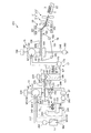
- FIG. 1 is a schematic configuration diagram of a sheet manufacturing apparatus (first embodiment) according to the present invention.
- FIG. 2 is a diagram sequentially illustrating steps performed by the sheet manufacturing apparatus illustrated in FIG. 1.
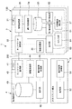
- FIG. 3 is a schematic view of the sheet manufacturing system (first embodiment) of the present invention.
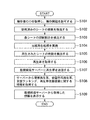
- FIG. 4 is a flowchart showing a control operation of the sheet manufacturing apparatus shown in FIG.
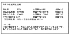
- FIG. 5 is a diagram illustrating an example of information displayed on the display unit illustrated in FIG. 3.
- FIG. 6 is a flowchart showing the control operation of the control unit provided in the second embodiment of the sheet manufacturing apparatus of the present invention.
- FIG. 7 is a diagram illustrating an example of information displayed on the display unit included in the second embodiment of the sheet manufacturing apparatus of the present invention.
- the sheet manufacturing apparatus 100 shown in FIG. 1 and FIG. 3 includes a first detection unit 61 that detects the amount of loaded sheets, a second detection unit 62 that detects the amount of recycled sheets, and a first detection unit 61. And a reproduction rate acquisition unit 34 (acquisition unit) that acquires a reproduction rate based on the detection result of the second detection unit 62.
- the present invention it is possible to grasp how much the sheet S can be regenerated with respect to the amount of the input sheet (raw material M1) by acquiring the regeneration rate. Therefore, it is possible to grasp how much the operator of the sheet manufacturing apparatus 100 contributes to ecology (hereinafter, used as an abbreviation of “ecology”), and the awareness of ecology can be further increased.
- the sheet manufacturing system 1 of the present invention shown in FIG. 3 includes a sheet manufacturing apparatus 100 of the present invention and a monitoring control server 4. That is, a first detection unit 61 that detects the amount of sheets put into the sheet manufacturing apparatus 100, a second detection unit 62 that detects the amount of reproduced sheets, a detection result of the first detection unit 61, A sheet production apparatus 100 including a reproduction rate acquisition unit 34 (acquisition unit) that obtains a reproduction rate based on a detection result of the second detection unit 62, and a monitoring central server 4 that monitors and supervises the sheet production apparatus 100. I have.
- the reproduction rate of the sheet manufacturing apparatus 100 can be grasped from the monitoring control server 4 while enjoying the advantages of the sheet manufacturing apparatus 100 of the present invention.
- FIG. 1 is a schematic configuration diagram of a sheet manufacturing apparatus (first embodiment) according to the present invention.
- FIG. 2 is a diagram sequentially illustrating steps performed by the sheet manufacturing apparatus illustrated in FIG. 1.
- FIG. 3 is a schematic view of the sheet manufacturing system (first embodiment) of the present invention.
- FIG. 4 is a flowchart showing a control operation of the sheet manufacturing apparatus shown in FIG.
- FIG. 5 is a diagram illustrating an example of information displayed on the display unit illustrated in FIG. 3.
- FIG. 1 the upper side of FIG. 1 is referred to as “upper” or “upper”, the lower side is referred to as “lower” or “lower”, the left side is referred to as “left” or “upstream side”, and the right side is referred to as “ Sometimes referred to as “right” or “downstream”.
- the sheet manufacturing system 1 of the present invention includes a sheet manufacturing apparatus 100 of the present invention and a monitoring control server 4. Further, the sheet manufacturing apparatus 100 and the monitoring central server 4 can communicate with each other via the network 300.
- 1 and 3 includes a raw material supply unit 11, a crushing unit 12, a defibrating unit 13, a sorting unit 14, a first web forming unit 15, and a subdividing unit 16. A part 17, a loosening part 18, a second web forming part 19, a sheet forming part 20, a cutting part 21, and a stock part 22 are provided. Further, the sheet manufacturing apparatus 100 includes a humidifying unit 231, a humidifying unit 232, a humidifying unit 233, a humidifying unit 234, a humidifying unit 235, a humidifying unit 236, the control unit 3, the first detecting unit 61, A second detection unit 62, a display unit 63, and an ID input unit 64 are provided. The operation of each unit included in the sheet manufacturing apparatus 100 is controlled by the control unit 3.
- the sheet manufacturing method includes a raw material supply process, a crushing process, a defibrating process, a sorting process, a first web forming process, a dividing process, and a mixing process. And a loosening step, a second web forming step, a sheet forming step, and a cutting step.
- the raw material supply part 11 is a part which performs the raw material supply process (refer FIG. 2) which supplies the raw material M1 to the crushing part 12.
- FIG. 2 As this raw material M1, it consists of the fiber containing material containing a fiber (cellulose fiber), for example, makes a sheet form.
- the raw material M1 is an example of waste paper in the present embodiment, but may be an unused sheet.
- the cellulose fiber is not particularly limited as long as it is mainly composed of cellulose (narrowly defined cellulose) as a compound and has a fibrous form. Good.
- the crushing unit 12 is a part that performs a crushing step (see FIG. 2) for crushing the raw material M1 supplied from the raw material supply unit 11 in the air (in the air).
- the crushing unit 12 has a pair of crushing blades 121 and a chute (hopper) 122.
- the pair of crushing blades 121 can rotate in opposite directions to crush the raw material M1 between them, that is, cut into a crushing piece M2.
- the shape and size of the coarsely crushed pieces M2 are preferably suitable for the defibrating process in the defibrating unit 13, and are preferably small pieces having a side length of 100 mm or less, for example, 10 mm or more and 70 mm or less. It is more preferable that
- the chute 122 is disposed below the pair of crushing blades 121 and has, for example, a funnel shape. Thereby, the chute
- a humidifying portion 231 is disposed adjacent to the pair of crushing blades 121.
- the humidifying unit 231 humidifies the coarse fragments M2 in the chute 122.
- This humidifying unit 231 has a filter (not shown) containing moisture, and a vaporization type (or a warm air vaporization type) that supplies humidified air with increased humidity to the coarse fragments M2 by allowing air to pass through the filter. It consists of a humidifier. By supplying the humidified air to the roughly crushed pieces M2, it is possible to suppress the roughly crushed pieces M2 from adhering to the chute 122 and the like due to static electricity.
- the chute 122 is connected to the defibrating unit 13 via a pipe (flow path) 241.
- the coarsely crushed pieces M2 collected on the chute 122 pass through the pipe 241 and are conveyed to the defibrating unit 13.
- the defibrating unit 13 is a part that performs a defibrating step (see FIG. 2) in which the coarsely crushed pieces M2 (fiber-containing material containing fibers) are defibrated in the air (in the air), that is, dry.
- the defibrated material M3 can be generated from the coarsely crushed pieces M2.
- “defibration” means to loosen the coarsely crushed piece M2 formed by binding a plurality of fibers into one fiber. Then, the unraveled material becomes the defibrated material M3.
- the shape of the defibrated material M3 is linear or strip-shaped. Further, the defibrated material M3 may exist in a state where they are entangled and formed into a lump, that is, in a state of forming a so-called “dama”.
- the defibrating unit 13 is configured by an impeller mill having a rotor that rotates at a high speed and a liner that is positioned on the outer periphery of the rotor.
- the coarsely crushed pieces M2 flowing into the defibrating unit 13 are defibrated by being sandwiched between the rotor and the liner.
- the defibrating unit 13 can generate an air flow (airflow) from the crushing unit 12 toward the sorting unit 14 by rotation of the rotor. Thereby, the coarsely crushed pieces M2 can be sucked into the defibrating unit 13 from the pipe 241.
- the defibrated material M3 can be sent out to the sorting unit 14 through the pipe 242.
- the defibrating unit 13 also has a function of separating the resin particles adhering to the defibrated material M3 (coarse pieces M2), coloring materials such as ink and toner, and materials such as a bleeding inhibitor from the fibers.
- the defibrating unit 13 is connected to the sorting unit 14 through a tube (flow path) 242.
- the defibrated material M3 fiber-containing material after defibration
- a blower 261 is installed in the middle of the pipe 242.
- the blower 261 is an airflow generation device that generates an airflow toward the sorting unit 14. Thereby, sending out of the defibrated material M3 to the sorting unit 14 is promoted.
- the sorting unit 14 is a part that performs a sorting step (see FIG. 2) for sorting the defibrated material M3 based on the length of the fiber.
- the defibrated material M3 is sorted into a first sorted product M4-1 and a second sorted product M4-2 that is larger than the first sorted product M4-1.
- the first selected item M4-1 has a size suitable for the subsequent manufacture of the sheet S (sheet material).
- Examples of the second selection product M4-2 include those in which defibration is insufficient and defibrated fibers are excessively aggregated.
- the sorting unit 14 includes a drum unit 141 and a housing unit 142 that houses the drum unit 141.
- the drum portion 141 is a sieve that is formed of a cylindrical mesh body and rotates around its central axis.
- the defibrated material M3 flows into the drum portion 141.
- the defibrated material M3 smaller than the mesh opening is selected as the first selected material M4-1, and the defibrated material M3 having a size larger than the mesh opening is Sorted as second sort M4-2.
- the first selected item M4-1 falls from the drum unit 141.
- the second selected item M4-2 is sent out to a pipe (flow path) 243 connected to the drum unit 141.
- the tube 243 is connected to the tube 241 on the opposite side (downstream side) of the drum portion 141.
- the second sorted matter M4-2 that has passed through the pipe 243 merges with the coarsely crushed pieces M2 in the pipe 241 and flows into the defibrating unit 13 together with the coarsely crushed pieces M2.
- the second selected matter M4-2 is returned to the defibrating unit 13 and defibrated together with the coarsely crushed pieces M2.
- the first selected matter M4-1 from the drum unit 141 falls while being dispersed in the air, and proceeds to the first web forming unit (separating unit) 15 located below the drum unit 141.
- the first web forming unit 15 is a part that performs a first web forming step (see FIG. 2) for forming the first web M5 from the first selected material M4-1.
- the first web forming unit 15 includes a mesh belt (separation belt) 151, three stretching rollers 152, and a suction unit (suction mechanism) 153.
- the mesh belt 151 is an endless belt, and the first selected matter M4-1 is deposited on the mesh belt 151.
- the mesh belt 151 is wound around three tension rollers 152. Then, by the rotational drive of the stretching roller 152, the first selected item M4-1 on the mesh belt 151 is conveyed downstream.
- the first selection M4-1 is larger than the mesh belt 151. As a result, the first selected matter M4-1 is restricted from passing through the mesh belt 151, and thus can be deposited on the mesh belt 151. Further, since the first selected matter M4-1 is deposited on the mesh belt 151 and conveyed to the downstream side together with the mesh belt 151, it is formed as a layered first web M5.
- the color material CM is mixed in the first selected item M4-1.
- the color material CM is smaller than the mesh belt 151. As a result, the color material CM passes through the mesh belt 151 and falls further downward.
- the suction unit 153 can suck air from below the mesh belt 151. Thereby, the color material CM that has passed through the mesh belt 151 can be sucked together with the air.
- suction unit 153 is connected to the recovery unit 27 via a tube (flow path) 244.
- the color material CM sucked by the suction unit 153 is collected by the collection unit 27.
- a pipe (flow path) 245 is further connected to the collection unit 27.
- a blower 262 is installed in the middle of the pipe 245. By the operation of the blower 262, a suction force can be generated in the suction portion 153. Thereby, formation of the 1st web M5 on the mesh belt 151 is accelerated
- the first web M5 is obtained by removing the color material CM. Further, the color material CM passes through the pipe 244 and reaches the collection unit 27 by the operation of the blower 262.
- the housing part 142 is connected to the humidifying part 232.
- the humidifying unit 232 includes a vaporizing humidifier similar to the humidifying unit 231. Thereby, humidified air is supplied into the housing part 142.
- the humidified air can humidify the first selected item M4-1, and thus it is possible to suppress the first selected item M4-1 from adhering to the inner wall of the housing part 142 due to electrostatic force.
- the humidification part 235 is arrange
- the humidifying unit 235 is composed of an ultrasonic humidifier that sprays water. Thereby, moisture can be supplied (humidified) to the first web M5, and thus the moisture content of the first web M5 is adjusted. By this adjustment, adsorption of the first web M5 to the mesh belt 151 due to electrostatic force can be suppressed. Accordingly, the first web M5 is easily peeled from the mesh belt 151 at a position where the mesh belt 151 is folded back by the stretching roller 152.
- the subdivision part 16 is arrange
- FIG. The subdivision part 16 is a part which performs the division
- FIG. The subdivision portion 16 includes a propeller 161 that is rotatably supported and a housing portion 162 that houses the propeller 161. And the 1st web M5 can be parted by the 1st web M5 being wound in the propeller 161 which rotates. The divided first web M5 becomes a subdivided body M6. Further, the subdivided body M6 descends in the housing portion 162.
- the housing part 162 is connected to the humidifying part 233.
- the humidifying unit 233 is configured by a vaporizing humidifier similar to the humidifying unit 231. Thereby, humidified air is supplied into the housing portion 162.
- the humidified air can also prevent the subdivided body M6 from adhering to the inner walls of the propeller 161 and the housing portion 162 due to electrostatic force.
- a mixing unit 17 is disposed downstream of the subdivision unit 16.
- the mixing part 17 is a part which performs the mixing process (refer FIG. 2) which mixes the subdivision M6 and resin P1.
- the mixing unit 17 includes a resin supply unit 171, a pipe (flow path) 172, and a blower 173.
- the pipe 172 connects the housing part 162 of the subdividing part 16 and the housing part 182 of the loosening part 18, and is a flow path through which the mixture M7 of the subdivided body M6 and the resin P1 passes.
- a resin supply unit 171 is connected in the middle of the pipe 172.
- the resin supply unit 171 has a screw feeder 174. By rotating the screw feeder 174, the resin P1 can be supplied to the pipe 172 as powder or particles.
- the resin P1 supplied to the pipe 172 is mixed with the subdivided body M6 to become a mixture M7.
- the resin P1 binds the fibers in a later step.
- a thermoplastic resin a curable resin, or the like can be used, but a thermoplastic resin is preferably used.
- the thermoplastic resin include AS resin, ABS resin, polyethylene, polypropylene, polyolefin such as ethylene-vinyl acetate copolymer (EVA), modified polyolefin, acrylic resin such as polymethyl methacrylate, polyvinyl chloride, polystyrene, and polyethylene.
- Polyester such as terephthalate, polybutylene terephthalate, nylon 6, nylon 46, nylon 66, nylon 610, nylon 612, nylon 11, nylon 12, nylon 6-12, nylon 6-66, polyamide (nylon), polyphenylene ether, polyacetal , Polyether, polyphenylene oxide, polyether ether ketone, polycarbonate, polyphenylene sulfide, thermoplastic polyimide, polyether imide, aromatic polymer Liquid crystalline polymers such as esters, various thermoplastic elastomers such as styrene, polyolefin, polyvinyl chloride, polyurethane, polyester, polyamide, polybutadiene, trans polyisoprene, fluororubber, chlorinated polyethylene, etc. 1 type selected from these, or 2 or more types can be used in combination.
- the thermoplastic resin polyester or one containing the same is used as the thermoplastic resin.
- what is supplied from the resin supply unit 171 includes, for example, a colorant for coloring the fiber, an aggregation inhibitor for suppressing aggregation of the fiber and the aggregation of the resin P1, fiber, and the like.
- a flame retardant for making it difficult to burn may be included.
- vegetable materials, such as starch, may be sufficient.
- a blower 173 is installed on the downstream side of the resin supply unit 171.
- the blower 173 can generate an air flow toward the loosening unit 18.
- the mixture M7 can flow into the loosening part 18 in a state where the subdivided body M6 and the resin P1 are uniformly dispersed.
- the subdivided body M6 in the mixture M7 is loosened in the process of passing through the tube 172, and becomes finer fibrous.
- the loosening part 18 is a part that performs a loosening step (see FIG. 2) of loosening fibers intertwined in the mixture M7.
- the loosening portion 18 includes a drum portion 181 and a housing portion 182 that houses the drum portion 181.
- the drum portion 181 is a sieve that is formed of a cylindrical net and rotates around its central axis.
- the mixture M7 flows into the drum portion 181.
- fibers or the like smaller than the mesh openings in the mixture M7 can pass through the drum portion 181. At that time, the mixture M7 is loosened.
- the 2nd web formation part 19 is a part which performs the 2nd web formation process (refer FIG. 2) which forms the 2nd web M8 from the mixture M7.
- the second web forming unit 19 includes a mesh belt (separation belt) 191, a tension roller 192, and a suction unit (suction mechanism) 193.
- the mesh belt 191 is an endless belt, and the mixture M7 is deposited thereon.
- the mesh belt 191 is wound around four stretching rollers 192. And the mixture M7 on the mesh belt 191 is conveyed downstream by the rotational drive of the tension roller 192.
- the mixture M7 on the mesh belt 191 is larger than the mesh belt 191.
- the mixture M7 is restricted from passing through the mesh belt 191, and can therefore be deposited on the mesh belt 191.
- the mixture M7 is conveyed on the downstream side with the mesh belt 191 while being deposited on the mesh belt 191, it is formed as a layered second web M8.
- the suction unit 193 can suck air from below the mesh belt 191. As a result, the mixture M7 can be sucked onto the mesh belt 191. Therefore, the deposition of the mixture M7 on the mesh belt 191 is promoted.
- a tube (flow path) 246 is connected to the suction unit 193.
- a blower 263 is installed in the middle of the pipe 246. By the operation of the blower 263, a suction force can be generated at the suction portion 193.
- the housing part 182 is connected to the humidifying part 234.
- the humidifying unit 234 includes a vaporizing humidifier similar to the humidifying unit 231. Thereby, humidified air is supplied into the housing portion 182.
- the inside of the housing part 182 can be humidified by the humidified air, so that the mixture M7 can be prevented from adhering to the inner wall of the housing part 182 by electrostatic force.
- a humidifying unit 236 is disposed on the downstream side of the loosening unit 18.
- the humidifying unit 236 is configured by an ultrasonic humidifier similar to the humidifying unit 235.
- moisture can be supplied to the second web M8, and thus the moisture content of the second web M8 is adjusted.
- adsorption of the second web M8 to the mesh belt 191 due to the electrostatic force can be suppressed.
- the second web M8 is easily peeled from the mesh belt 191 at a position where the mesh belt 191 is folded back by the stretching roller 192.
- the sheet forming unit 20 is disposed on the downstream side of the second web forming unit 19.
- the sheet forming unit 20 is a part that performs a sheet forming step (see FIG. 2) for forming the sheet S from the second web M8.
- the sheet forming unit 20 includes a pressurizing unit 201 and a heating unit 202.
- the pressing unit 201 includes a pair of calendar rollers 203, and can press the second web M8 without heating between them. Thereby, the density of the 2nd web M8 is raised. Then, the second web M8 is conveyed toward the heating unit 202.
- One of the pair of calendar rollers 203 is a main driving roller driven by the operation of a motor (not shown), and the other is a driven roller.
- the heating unit 202 includes a pair of heating rollers 204, and can pressurize the second web M8 while heating the second web M8 therebetween. By this heating and pressing, the resin P1 is melted in the second web M8, and the fibers are bound to each other through the melted resin P1. Thereby, the sheet S is formed. The sheet S is conveyed toward the cutting unit 21.
- One of the pair of heating rollers 204 is a main driving roller driven by the operation of a motor (not shown), and the other is a driven roller.
- a cutting unit 21 is disposed on the downstream side of the sheet forming unit 20.
- the cutting unit 21 is a part that performs a cutting process (see FIG. 2) for cutting the sheet S.
- the cutting unit 21 includes a first cutter 211 and a second cutter 212.
- the first cutter 211 cuts the sheet S in a direction that intersects the conveying direction of the sheet S.
- the second cutter 212 cuts the sheet S in a direction parallel to the conveying direction of the sheet S on the downstream side of the first cutter 211.
- the sheet S having a desired size is obtained by cutting the first cutter 211 and the second cutter 212.
- the sheet S is further conveyed downstream and accumulated in the stock unit 22.
- control unit 3 includes a CPU 31 (Central Processing Unit), a network connection unit 32, a storage unit 33, a playback rate acquisition unit 34, an information transmission unit 35, an information reception unit 36, A print ratio detection unit 37.
- CPU 31 Central Processing Unit
- network connection unit 32 a network connection unit 22
- storage unit 33 a storage unit 33
- playback rate acquisition unit 34 a playback rate acquisition unit 34
- information transmission unit 35 an information reception unit 36
- print ratio detection unit 37 A print ratio detection unit 37.
- the CPU 31 controls the operation of the sheet manufacturing apparatus 100.
- the CPU 31 controls each unit based on various programs stored in the storage unit 33.
- the network connection unit 32 communicates with the monitoring control server 4 via the network 300.
- the network 300 is not particularly limited, and examples thereof include a LAN (Local Area Network), a WAN (Wide Area Network), a MAN (Metropolitan Area Network), and the Internet.
- the storage unit 33 is composed of, for example, a rewritable nonvolatile memory, and information such as a reproduction rate of the sheet manufacturing apparatus 100 and various programs are executed by the CPU 31 in the storage unit 33.
- the storage unit 33 stores the reproduction rate for each operator. That is, the reproduction rate is stored for each piece of identification information input to the ID input unit 64. Thereby, the reproduction rate for each operator can be transmitted to the monitoring control server 4.
- the regeneration rate acquisition unit 34 acquires the regeneration rate based on the amount of the sheet (raw material M1) input to the sheet manufacturing apparatus 100 and the amount of the regenerated sheet S.
- the playback rate acquisition unit 34 may acquire the playback rate by calculation or may acquire the playback rate based on a prestored table, but in the present embodiment, the playback rate is acquired by calculation. Shall. Further, in the sheet manufacturing apparatus 100, information related to the reproduction rate acquired by the reproduction rate acquisition unit 34 can be displayed on the display unit 63.
- the information transmission unit 35 transmits information such as a reproduction rate to the monitoring control server 4 via the network connection unit 32.
- the information receiving unit 36 receives the playback rate tabulation results from the monitoring control server 4 via the network connection unit 32.
- the received counting result is displayed on the display unit 63.
- the network connection unit 32, the information transmission unit 35, and the information reception unit 36 constitute a communication unit that outputs information including a reproduction rate.
- information including the reproduction rate can be transmitted to the monitoring management server 4. Therefore, as will be described later, the monitoring management server 4 can display the analysis result obtained by analyzing the regeneration rate of the sheet manufacturing apparatus 100 on the display unit 63.
- the printing ratio detection unit 37 detects the ratio of the printing area in the raw material M1 (the sheet put into the sheet manufacturing apparatus 100). Thereby, as will be described later, for example, when the printing area exceeds a predetermined ratio, that is, when the amount of the sheet S to be regenerated with respect to the supplied raw material M1 is small and the efficiency is low, that is the case. Is displayed on the display unit 63, so that the reproduction rate can be increased. Therefore, it contributes to the improvement of the reproduction rate.
- the printing ratio detection unit 37 can be configured to realize the above by, for example, imaging the raw material M1 and detecting a printing region in the imaging result.
- the first detection unit 61 detects the amount of the sheet (raw material M1) put into the sheet manufacturing apparatus 100.
- the first detection unit 61 can be configured by, for example, an optical sensor, and can detect the number of raw materials M1 by detecting the light blocking state when the raw material M1 passes. it can.
- the first detector 61 is connected to the controller 3 and its operation is controlled.
- the second detection unit 62 detects the amount of the regenerated sheet S.
- the second detection unit 62 can be configured by, for example, an optical sensor, and can detect the number of sheets S by detecting a light blocking state when the sheet S passes. it can.
- the second detector 62 is connected to the controller 3 and its operation is controlled.
- the first detection unit 61 detects the number of sheets (raw material M1) put into the sheet manufacturing apparatus 100, and the second detection unit 62 detects the number of sheets S that have been regenerated.
- the reproduction rate can be acquired by a simple method of detecting the number of sheets.
- the reproduction rate when the reproduction rate is acquired, it can be acquired by a simple operation of dividing an integer by an integer.
- the first detection unit 61 detects the weight of the sheet (raw material M1) put into the sheet manufacturing apparatus 100, and the second detection unit 62 detects the weight of the regenerated sheet S. May be. Thereby, even if the sizes of the raw material M1 and the sheet S are different, the regeneration rate can be accurately acquired.
- the display unit 63 is composed of a monitor and can display various information such as a playback rate described later. That is, the display unit 63 functions as a notification unit that notifies information such as a playback rate. Thereby, the playback rate can be notified to the operator.
- the display unit 63 is electrically connected to the control unit 3 and its operation is controlled.
- the ID input unit 64 is for inputting identification information of the operator of the sheet manufacturing apparatus 100.
- a known method such as an input unit in which an operator manually inputs his / her ID or a reader for reading a barcode held by the operator can be applied.
- the monitoring central server 4 includes a CPU 41, a network connection unit 42, a storage unit 43, an information receiving unit 44, a totaling unit 45, and a totaling result transmitting unit 46.
- the CPU 41 executes various programs in the same manner as the CPU 31.
- the network connection unit 42 communicates with the network connection unit 32 via the network 300.
- Various programs are stored in the storage unit 43.
- the storage unit 43 stores information such as a reproduction rate transmitted from the sheet manufacturing apparatus 100.
- the information receiving unit 44 receives information such as a reproduction rate from the sheet manufacturing apparatus 100 via the network connection unit 42 and stores the information in the storage unit 43.
- the tabulation unit 45 tabulates information such as the playback rate stored in the storage unit 43.
- the counting result transmission unit 46 transmits the counting result of the counting unit 45 to the counting result receiving unit 51 of the client terminal 5.
- the aggregation result received by the aggregation result receiving unit 51 is displayed on the display unit 52 of the client terminal 5.
- the operator turns on the sheet manufacturing apparatus 100 and inputs an ID to the ID input unit 64.
- the input ID is acquired, and the operation of the sheet manufacturing apparatus 100 is started (step S101).
- step S102 the number of the raw materials M1 input by the operator to the raw material supply unit 11 shown in FIG. 1 is detected by the first detection unit 61 shown in FIG.
- step S103 the printing ratio detection unit 37 shown in FIG. 3 detects the printing ratio for each raw material.
- step S104 the used paper recycling process, that is, the manufacture of the sheet S is started.
- step S105 the number of reproduced sheets S is detected.
- step S106 the reproduction rate is calculated by dividing the number of detected sheets S by the number of raw materials M1 detected in step S102.
- the reproduction rate calculated in step S106 is transmitted to the monitoring control server 4 (step S107).
- the monitoring management server 4 performs analysis based on the reproduction rate received from the sheet manufacturing apparatus 100, and manufactures “ideal reproduction rate”, “national average reproduction rate”, “national ranking”, and “regeneration rate improvement plan” sheet production. Transmit to device 100.
- the “ideal reproduction rate” is an ideal value set in advance, and is stored in the storage unit 43 of the monitoring control server 4.
- the “national average reproduction rate” is a value calculated by the CPU 41 from the average value of the reproduction rates acquired from all the sheet manufacturing apparatuses connected to the monitoring management server 4 via the network 300.
- “Nationwide ranking” is a ranking in which the reproduction rates are ranked in order from the top for all the sheet manufacturing apparatuses connected to the monitoring management server 4 via the network 300.
- the “reproduction rate improvement plan” is stored in advance in the storage unit 43 of the monitoring control server 4 in accordance with the reproduction rate.
- Step S108 the “ideal playback rate”, “national average playback rate”, “national ranking”, and “playback rate improvement plan” are received from the monitoring control server 4.
- step S109 information such as “ideal reproduction rate”, “national average reproduction rate”, “national ranking”, and “reproduction rate improvement plan” is displayed (see FIG. 5).
- FIG. 5 shows an example of “ideal reproduction rate”, “national average reproduction rate”, “national ranking”, and “reproduction rate improvement plan” displayed on the display unit 63. Note that FIG. 5 shows the cumulative total of the sheet manufacturing apparatus 100 for each month.
- the “regeneration rate” of the sheet manufacturing apparatus 100 was 50%.
- “number of used paper sheets” indicates the total number of raw materials M1 supplied to the sheet manufacturing apparatus 100 and is 3000 sheets.
- the “reproduced number of sheets” indicates the total number of manufactured sheets S and is 1500 sheets.
- the national average “regeneration rate” is 65%
- the “average number of used paper” is 2500
- the “average number of recycled” is 1300.
- the “reproduction rate” of the sheet manufacturing apparatus 100 is the 42nd place in the whole country
- the “number of used paper sheets” of the sheet manufacturing apparatus 100 is the 25th place in the whole country
- the “reproduced number” of the sheet manufacturing apparatus 100 is Ranked 35th nationwide.
- the “average printing ratio” shown in FIG. 5 indicates the printing ratio occupied by the printing area in the raw material M1.
- the “average printing ratio” of the sheet manufacturing apparatus 100 is 9.3%, and the “average printing ratio” of the national average is 6.2%. Further, the “average printing ratio” of the sheet manufacturing apparatus 100 is the 12th place nationwide.
- ideal reproduction rate 72% ⁇ ideal printing rate 5%> is displayed below “average printing rate” in FIG. 5.
- the ideal reproduction rate is 72% and the ideal printing rate is 5%. It shows that there is.
- the playback rate of the operator himself the ideal playback rate, the national average playback rate, the national ranking and the playback rate improvement plan are displayed.
- the operator's own playback rate can be compared with other operators. Therefore, the operator's awareness of ecology can be further increased.
- the display of the improvement plan for the reproduction rate shows that what should be specifically done to improve the operator's own reproduction rate. Therefore, it contributes to the improvement of the reproduction rate.
- the sheet manufacturing apparatus 100 how much the sheet S is regenerated with respect to the amount of the sheet (raw material M1) put into the sheet manufacturing apparatus 100 by acquiring the regeneration rate. You can see if it was done. Therefore, it is possible to grasp how much the operator of the sheet manufacturing apparatus 100 contributes to the ecology and to further increase the eco-consciousness.
- the monitoring central server 4 since the monitoring central server 4 has a function of analyzing the reproduction rate of the sheet manufacturing apparatus 100, the reproduction rate of the sheet manufacturing apparatus 100 is analyzed, for example, “ideal reproduction rate”. Analysis results such as “National average regeneration rate”, “National ranking”, and “Regeneration rate improvement plan” can be transmitted to the sheet manufacturing apparatus 100.
- the communication unit (network connection unit 32, information transmission unit 35, and information reception unit 36) can acquire information including the reproduction rate of other sheet manufacturing apparatuses. For this reason, the operator's competitiveness can be enhanced and the eco-consciousness can be enhanced.
- FIG. 6 is a flowchart showing the control operation of the control unit provided in the second embodiment of the sheet manufacturing apparatus of the present invention.
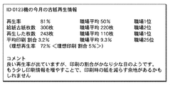
- FIG. 7 is a diagram illustrating an example of information displayed on the display unit included in the second embodiment of the sheet manufacturing apparatus of the present invention.
- This embodiment is the same as the first embodiment except that the control operation of the sheet manufacturing apparatus is different.
- Steps S201 and S202 in the flowchart of FIG. 6 are steps performed after performing steps S101 to S108 described in the first embodiment. That is, step S109 of the first embodiment is omitted, and in this embodiment, S201 and step S202 are performed.
- the storage unit 43 of the monitoring control server 4 stores information regarding the workplace to which the operator belongs.
- step S201 the average workplace replay rate and workplace ranking are received from the monitoring management server 4.
- the average workplace replay rate and workplace ranking are received from the monitoring management server 4.
- step S202 “ideal playback rate”, “national average playback rate”, “national ranking”, “playback rate improvement plan”, “workplace average playback rate”, and “workplace ranking” are displayed (see FIG. 7). ).
- FIG. 7 the analysis results shown in FIG. 7 will be described, but only differences from FIG. 5 will be described.
- FIG. 7 shows an example of “ideal reproduction rate”, “national average reproduction rate”, “national ranking”, and “reproduction rate improvement plan” displayed on the display unit 63.
- FIG. 7 shows cumulative information for each individual month of the operator (ID: 0123).
- the “reproduction rate” of the operator was 81%.
- “number of used paper sheets” indicates the total number of raw materials M1 supplied to the sheet manufacturing apparatus 100 by the operator (ID: 0123), which is 300 sheets.
- the “reproduced number of sheets” indicates the total number of manufactured sheets S and is 243 sheets.
- the “recycle rate” of the workplace average is 50%
- the workplace average of “the number of used paper” is 220
- the workplace average of “the number of recycled paper” is 110.
- the “average printing ratio” shown in FIG. 7 indicates the printing ratio occupied by the printing area in the raw material M1.
- the “average printing ratio” of the sheet manufacturing apparatus 100 is 3.2%, and the “average printing ratio” of the workplace average is 9.3%. Further, the “average printing ratio” of the sheet manufacturing apparatus 100 is the 25th place nationwide.
- the operator's own “regeneration rate”, “ideal regeneration rate”, “workplace average regeneration rate”, “workplace ranking”, and “reproduction rate improvement plan” are displayed.
- “workplace average replay rate” and “workplace ranking” it is possible to compare with the replay rates of other familiar operators. Therefore, the operator's awareness of ecology can be further increased.
- each part which comprises a sheet manufacturing apparatus and a sheet manufacturing system can be substituted with the thing of the arbitrary structures which can exhibit the same function.
- arbitrary components may be added.
- the sheet manufacturing apparatus and the sheet manufacturing system of the present invention may be a combination of any two or more configurations (features) of the above embodiments.
- the first detection unit detects either the number or weight of sheets fed into the sheet manufacturing apparatus 100
- the second detection unit detects the number and weight of reproduced sheets.
- the present invention is not limited to this.
- the first detection unit detects both the number and weight of sheets loaded into the sheet manufacturing apparatus 100
- the second detection unit may detect both the number and weight of the reproduced sheets.
- the present invention is not limited to this, and the control unit of the sheet manufacturing apparatus may have the analysis function.
- control unit In each of the above embodiments, the configuration in which the control unit is built in the sheet manufacturing apparatus has been described. However, the present invention is not limited to this, and the control unit may be externally connected to the sheet manufacturing apparatus.
- the notification unit is a monitor.
- the notification unit may be configured to notify by voice, and a function of notifying by voice may be added.
- DESCRIPTION OF SYMBOLS 100 Sheet manufacturing apparatus, 300 ... Network, 1 ... Sheet manufacturing system, 3 ... Control part, 31 ... CPU, 32 ... Network connection part, 33 ... Memory
- Second cutter, 22 Stock part, 201 ... Pressure part, 202: heating unit, 203: calendar roller, 204: heating roller, 231 ... humidification unit, 232 ... humidification unit, 233 ... humidification unit, 234 ... humidification unit, 235 ... humidification unit, 236 ... humidification unit, 241 ... pipe, 242 Pipe, 243 ... Pipe, 244 ... Pipe, 245 ... Pipe, 246 ... Pipe, 261 ... Blower, 262 ... Blower, 263 ... Blower, 27 ... Collection part, 61 ... DESCRIPTION OF SYMBOLS 1 detection part, 62 ... 2nd detection part, 63 ... Display part, 64 ... ID input part, CM ...
Landscapes
- Engineering & Computer Science (AREA)
- Life Sciences & Earth Sciences (AREA)
- Textile Engineering (AREA)
- Manufacturing & Machinery (AREA)
- Wood Science & Technology (AREA)
- Forests & Forestry (AREA)
- Dry Formation Of Fiberboard And The Like (AREA)
- Nonwoven Fabrics (AREA)
- Paper (AREA)
Abstract
再生率を把握することができるシート製造装置およびシート製造システムを提供することを提供すること。 本発明のシート製造装置は、投入されたシートの量を検出する第1検出部と、再生されたシートの量を検出する第2検出部と、前記第1検出部の検出結果と、前記第2検出部との検出結果とに基づいて再生率を取得する取得部と、を備える。また、シート製造装置は、前記再生率を含む情報を出力する通信部を備える。
Description
本発明は、シート製造装置およびシート製造システムに関する。
近年では、環境への意識が高まり、職場での紙(記録媒体)の使用量の削減だけではなく、職場で紙の再生を行なうことが求められている。
記録媒体を再生する方法としては、古紙を離解処理しパルプ懸濁液を製造するパルプ懸濁液製造部と、パルプ懸濁液を抄紙し、再生紙を製造する抄紙部とを有する古紙再生処理装置が知られている(例えば、特許文献1参照)。
また、特許文献1に記載の古紙再生処理装置では、古紙再生処理、または古紙再生処理後のパルプ懸濁液製造部および抄紙部の洗浄処理における動作情報を含む運転状態情報を、通信回線を通じて接続された端末機器へ送信する機能を有する。
ところで、古紙再生処理装置では、原料として投入した古紙からどのくらい再生紙が製造できているか示す再生率を知ることは容易ではなかった。
本発明のいくつかの態様に係る目的の1つは、再生率を把握することができるシート製造装置およびシート製造システムを提供することにある。
本発明は、上述の課題の少なくとも一部を解決するためになされたものであり、以下の態様として実現することが可能である。
本発明のシート製造装置は、投入されたシートの量を検出する第1検出部と、
再生されたシートの量を検出する第2検出部と、
前記第1検出部の検出結果と、前記第2検出部との検出結果とに基づいて再生率を取得する取得部と、を備える。
再生されたシートの量を検出する第2検出部と、
前記第1検出部の検出結果と、前記第2検出部との検出結果とに基づいて再生率を取得する取得部と、を備える。
本発明によれば、再生率を取得することにより、投入されたシートの量に対して、どの程度シートを再生することができたかを把握することができる。よって、シート製造装置の操作者が、どの程度エコ(以下、「ecology」の略語として使用する)に貢献しているかを把握することができ、エコへの意識をより高めることができる。
本発明のシート製造装置では、前記第1検出部は、前記投入されたシートの重さを検出し、
前記第2検出部は、前記再生されたシートの重さを検出するのが好ましい。
前記第2検出部は、前記再生されたシートの重さを検出するのが好ましい。
これにより、投入されたシートと再生されたシートの大きさが違ったとしても、正確に再生率を取得することができる。
本発明のシート製造装置では、前記第1検出部は、前記投入されたシートの枚数を検出し、
前記第2検出部は、前記再生されたシートの枚数を検出するのが好ましい。
前記第2検出部は、前記再生されたシートの枚数を検出するのが好ましい。
これにより、枚数を検出するという簡単な方法で、再生率を取得することができる。また、再生率を取得する際、整数を整数で除算するという簡単な演算により、取得することができる。
本発明のシート製造装置では、前記投入されたシートは、印刷により印刷領域が形成されたものであり、
前記投入されたシートにおける前記印刷領域の割合を検出する印刷割合検出部を備えるのが好ましい。
前記投入されたシートにおける前記印刷領域の割合を検出する印刷割合検出部を備えるのが好ましい。
これにより、例えば、印刷領域が所定の割合を超えている場合、すなわち、供給した原料M1に対して再生されるシートの量が少なく、効率が悪い場合には、その旨を報知することにより、再生率を高めることができる。よって、再生率の改善に寄与する。
本発明のシート製造装置では、前記再生率を含む情報を出力する通信部を備えるのが好ましい。
これにより、再生率を含む情報を例えば監視統括サーバーに送信することができる。
これにより、再生率を含む情報を例えば監視統括サーバーに送信することができる。
本発明のシート製造装置では、前記通信部は、他のシート製造装置の前記再生率を含む情報を取得可能であるのが好ましい。
これにより、他のシート製造装置の再生率を含む情報を取得することができる。よって、操作者は、自身の再生率と他のシート製造装置の再生率とを比較することができる。
本発明のシート製造装置では、当該シート製造装置の操作者の識別情報を入力するID入力部と、
前記操作者ごとに前記再生率を記憶する記憶部と、を備えるのが好ましい。
これにより、操作者ごとの再生率を監視統括サーバーに送信することができる。
前記操作者ごとに前記再生率を記憶する記憶部と、を備えるのが好ましい。
これにより、操作者ごとの再生率を監視統括サーバーに送信することができる。
本発明のシート製造装置では、前記再生率を報知する報知部を備えるのが好ましい。
これにより、操作者に再生率を報知することができる。
これにより、操作者に再生率を報知することができる。
本発明のシート製造システムは、シートの再生に供される投入されたシートの量を検出する第1検出部と、再生されたシートの量を検出する第2検出部と、前記第1検出部の検出結果と、前記第2検出部との検出結果とに基づいて再生率を取得する取得部とを有するシート製造装置と、
前記シート製造装置を監視統括する監視統括サーバーと、を備えることを特徴とする。
前記シート製造装置を監視統括する監視統括サーバーと、を備えることを特徴とする。
これにより、本発明のシート製造装置の利点を享受しつつ、監視統括サーバーからも、シート製造装置の再生率を把握することができる。
本発明のシート製造システムでは、前記監視統括サーバーは、前記再生率を分析する機能を有するのが好ましい。
これにより、シート製造装置の再生率を分析することができる。
これにより、シート製造装置の再生率を分析することができる。
以下、本発明のシート製造装置およびシート製造システムを添付図面に示す好適な実施形態に基づいて詳細に説明する。
図1および図3に示すシート製造装置100は、投入されたシートの量を検出する第1検出部61と、再生されたシートの量を検出する第2検出部62と、第1検出部61の検出結果と、第2検出部62との検出結果とに基づいて再生率を取得する再生率取得部34(取得部)と、を備える。
本発明によれば、再生率を取得することにより、投入されたシート(原料M1)の量に対して、どの程度シートSを再生することができたかを把握することができる。よって、シート製造装置100の操作者が、どの程度エコ(以下、「ecology」の略語として使用する)に貢献しているかを把握することができ、エコへの意識をより高めることができる。
また、図3に示す本発明のシート製造システム1は、本発明のシート製造装置100と、監視統括サーバー4とを備える。すなわち、シート製造装置100に投入されたシートの量を検出する第1検出部61と、再生されたシートの量を検出する第2検出部62と、第1検出部61の検出結果と、第2検出部62との検出結果とに基づいて再生率を取得する再生率取得部34(取得部)とを備えるシート製造装置100と、シート製造装置100を監視統括する監視統括サーバー4と、を備えている。
これにより、本発明のシート製造装置100の利点を享受しつつ、監視統括サーバー4からも、シート製造装置100の再生率を把握することができる。
<第1実施形態>
図1は、本発明のシート製造装置(第1実施形態)の概略構成図である。図2は、図1に示すシート製造装置が実行する工程を順に示す図である。図3は、本発明のシート製造システム(第1実施形態)の概略図である。図4は、図1に示すシート製造装置の制御動作を示すフローチャートである。図5は、図3に示す表示部に表示される情報の一例を示す図である。
図1は、本発明のシート製造装置(第1実施形態)の概略構成図である。図2は、図1に示すシート製造装置が実行する工程を順に示す図である。図3は、本発明のシート製造システム(第1実施形態)の概略図である。図4は、図1に示すシート製造装置の制御動作を示すフローチャートである。図5は、図3に示す表示部に表示される情報の一例を示す図である。
なお、以下では、説明の都合上、図1の上側を「上」または「上方」、下側を「下」または「下方」と言い、左側を「左」または「上流側」、右側を「右」または「下流側」と言うことがある。
図3に示すように、本発明のシート製造システム1は、本発明のシート製造装置100と、監視統括サーバー4とを備えている。また、シート製造装置100と監視統括サーバー4とはネットワーク300を介して通信可能である。
まず、シート製造装置100について説明する。
図1および図3に示すシート製造装置100は、原料供給部11と、粗砕部12と、解繊部13と、選別部14と、第1ウェブ形成部15と、細分部16と、混合部17と、ほぐし部18と、第2ウェブ形成部19と、シート形成部20と、切断部21と、ストック部22とを備えている。また、シート製造装置100は、加湿部231と、加湿部232と、加湿部233と、加湿部234と、加湿部235と、加湿部236と、制御部3と、第1検出部61と、第2検出部62と、表示部63と、ID入力部64とを備えている。シート製造装置100が備える各部の作動は、制御部3によって制御されている。
図1および図3に示すシート製造装置100は、原料供給部11と、粗砕部12と、解繊部13と、選別部14と、第1ウェブ形成部15と、細分部16と、混合部17と、ほぐし部18と、第2ウェブ形成部19と、シート形成部20と、切断部21と、ストック部22とを備えている。また、シート製造装置100は、加湿部231と、加湿部232と、加湿部233と、加湿部234と、加湿部235と、加湿部236と、制御部3と、第1検出部61と、第2検出部62と、表示部63と、ID入力部64とを備えている。シート製造装置100が備える各部の作動は、制御部3によって制御されている。
図2に示すように、本実施形態では、シートの製造方法は、原料供給工程と、粗砕工程と、解繊工程と、選別工程と、第1ウェブ形成工程と、分断工程と、混合工程と、ほぐし工程と、第2ウェブ形成工程と、シート形成工程と、切断工程とを有する。
以下、シート製造装置100が備える各部の構成について説明する。
原料供給部11は、粗砕部12に原料M1を供給する原料供給工程(図2参照)を行なう部分である。この原料M1としては、繊維(セルロース繊維)を含む繊維含有材料で構成された、例えばシート状をなすものである。また、原料M1は、本実施形態では、古紙を一例としているが、未使用のシートであってもよい。なお、セルロース繊維とは、化合物としてのセルロース(狭義のセルロース)を主成分とし繊維状をなすものであればよく、セルロース(狭義のセルロース)の他に、ヘミセルロース、リグニンを含むものであってもよい。
原料供給部11は、粗砕部12に原料M1を供給する原料供給工程(図2参照)を行なう部分である。この原料M1としては、繊維(セルロース繊維)を含む繊維含有材料で構成された、例えばシート状をなすものである。また、原料M1は、本実施形態では、古紙を一例としているが、未使用のシートであってもよい。なお、セルロース繊維とは、化合物としてのセルロース(狭義のセルロース)を主成分とし繊維状をなすものであればよく、セルロース(狭義のセルロース)の他に、ヘミセルロース、リグニンを含むものであってもよい。
粗砕部12は、原料供給部11から供給された原料M1を気中(空気中)で粗砕する粗砕工程(図2参照)を行なう部分である。粗砕部12は、一対の粗砕刃121と、シュート(ホッパー)122とを有している。
一対の粗砕刃121は、互いに反対方向に回転することにより、これらの間で原料M1を粗砕して、すなわち、裁断して粗砕片M2にすることができる。粗砕片M2の形状や大きさは、解繊部13における解繊処理に適しているのが好ましく、例えば、1辺の長さが100mm以下の小片であるのが好ましく、10mm以上70mm以下の小片であるのがより好ましい。
シュート122は、一対の粗砕刃121の下方に配置され、例えば漏斗状をなすものとなっている。これにより、シュート122は、粗砕刃121によって粗砕されて落下してきた粗砕片M2を受けることができる。
また、シュート122の上方には、加湿部231が一対の粗砕刃121に隣り合って配置されている。加湿部231は、シュート122内の粗砕片M2を加湿するものである。この加湿部231は、水分を含むフィルター(図示せず)を有し、フィルターに空気を通過させることにより、湿度を高めた加湿空気を粗砕片M2に供給する気化式(または温風気化式)の加湿器で構成されている。加湿空気が粗砕片M2に供給されることにより、粗砕片M2が静電気によってシュート122等に付着するのを抑制することができる。
シュート122は、管(流路)241を介して、解繊部13に接続されている。シュート122に集められた粗砕片M2は、管241を通過して、解繊部13に搬送される。
解繊部13は、粗砕片M2(繊維を含む繊維含有材料)を気中(空気中)で、すなわち、乾式で解繊する解繊工程(図2参照)を行なう部分である。この解繊部13での解繊処理により、粗砕片M2から解繊物M3を生成することができる。ここで「解繊する」とは、複数の繊維が結着されてなる粗砕片M2を、繊維1本1本に解きほぐすことをいう。そして、この解きほぐされたものが解繊物M3となる。解繊物M3の形状は、線状や帯状である。また、解繊物M3同士は、絡み合って塊状となった状態、すなわち、いわゆる「ダマ」を形成している状態で存在してもよい。
解繊部13は、例えば本実施形態では、高速回転するローターと、ローターの外周に位置するライナーとを有するインペラーミルで構成されている。解繊部13に流入してきた粗砕片M2は、ローターとライナーとの間に挟まれて解繊される。
また、解繊部13は、ローターの回転により、粗砕部12から選別部14に向かう空気の流れ(気流)を発生させることができる。これにより、粗砕片M2を管241から解繊部13に吸引することができる。また、解繊処理後、解繊物M3を、管242を介して選別部14に送り出すことができる。
解繊部13は、解繊物M3(粗砕片M2)に付着した樹脂粒や、インク、トナー等の色材、にじみ防止剤等の物質を、繊維から分離させる機能も有する。
また、解繊部13は、管(流路)242を介して、選別部14に接続されている。解繊物M3(解繊後の繊維含有材料)は、管242を通過して、選別部14に搬送される。
管242の途中には、ブロアー261が設置されている。ブロアー261は、選別部14に向かう気流を発生させる気流発生装置である。これにより、選別部14への解繊物M3の送り出しが促進される。
選別部14は、解繊物M3を、繊維の長さの大小によって選別する選別工程(図2参照)を行なう部分である。選別部14では、解繊物M3は、第1選別物M4-1と、第1選別物M4-1よりも大きい第2選別物M4-2とに選別される。第1選別物M4-1は、その後のシートS(シート材)の製造に適した大きさのものとなっている。第2選別物M4-2は、例えば、解繊が不十分なものや、解繊された繊維同士が過剰に凝集したもの等が含まれる。
選別部14は、ドラム部141と、ドラム部141を収納するハウジング部142とを有する。
ドラム部141は、円筒状をなす網体で構成され、その中心軸回りに回転する篩である。このドラム部141には、解繊物M3が流入してくる。そして、ドラム部141が回転することにより、網の目開きよりも小さい解繊物M3は、第1選別物M4-1として選別され、網の目開き以上の大きさの解繊物M3は、第2選別物M4-2として選別される。
第1選別物M4-1は、ドラム部141から落下する。
第1選別物M4-1は、ドラム部141から落下する。
一方、第2選別物M4-2は、ドラム部141に接続されている管(流路)243に送り出される。管243は、ドラム部141と反対側(下流側)が管241とに接続されている。この管243を通過した第2選別物M4-2は、管241内で粗砕片M2と合流して、粗砕片M2とともに解繊部13に流入する。これにより、第2選別物M4-2は、解繊部13に戻されて、粗砕片M2とともに解繊処理される。
また、ドラム部141からの第1選別物M4-1は、空気中に分散しつつ落下して、ドラム部141の下方に位置する第1ウェブ形成部(分離部)15に向かう。第1ウェブ形成部15は、第1選別物M4-1から第1ウェブM5を形成する第1ウェブ形成工程(図2参照)を行なう部分である。第1ウェブ形成部15は、メッシュベルト(分離ベルト)151と、3つの張架ローラー152と、吸引部(サクション機構)153とを有している。
メッシュベルト151は、無端ベルトであり、第1選別物M4-1が堆積する。このメッシュベルト151は、3つの張架ローラー152に掛け回されている。そして、張架ローラー152の回転駆動により、メッシュベルト151上の第1選別物M4-1は、下流側に搬送される。
第1選別物M4-1は、メッシュベルト151の目開き以上の大きさとなっている。これにより、第1選別物M4-1は、メッシュベルト151の通過が規制され、よって、メッシュベルト151上に堆積することができる。また、第1選別物M4-1は、メッシュベルト151上に堆積しつつ、メッシュベルト151ごと下流側に搬送されるため、層状の第1ウェブM5として形成される。
また、第1選別物M4-1には、色材CMが混在している。この色材CMは、メッシュベルト151の目開きよりも小さい。これにより、色材CMは、メッシュベルト151を通過して、さらに下方に落下する。
吸引部153は、メッシュベルト151の下方から空気を吸引することができる。これにより、メッシュベルト151を通過した色材CMを空気ごと吸引することができる。
また、吸引部153は、管(流路)244を介して、回収部27に接続されている。吸引部153で吸引された色材CMは、回収部27に回収される。
回収部27には、管(流路)245がさらに接続されている。また、管245の途中には、ブロアー262が設置されている。このブロアー262の作動により、吸引部153で吸引力を生じさせることができる。これにより、メッシュベルト151上における第1ウェブM5の形成が促進される。この第1ウェブM5は、色材CMが除去されたものとなる。また、色材CMは、ブロアー262の作動により、管244を通過して、回収部27まで到達する。
ハウジング部142は、加湿部232と接続されている。加湿部232は、加湿部231と同様の気化式の加湿器で構成されている。これにより、ハウジング部142内には、加湿空気が供給される。この加湿空気により、第1選別物M4-1を加湿することができ、よって、第1選別物M4-1がハウジング部142の内壁に静電力によって付着してしまうのを抑制することもできる。
選別部14の下流側には、加湿部235が配置されている。加湿部235は、水を噴霧する超音波式加湿器で構成されている。これにより、第1ウェブM5に水分を供給(加湿)することができ、よって、第1ウェブM5の水分量が調整される。この調整により、静電力による第1ウェブM5のメッシュベルト151への吸着を抑制することができる。これにより、第1ウェブM5は、メッシュベルト151が張架ローラー152で折り返される位置で、メッシュベルト151から容易に剥離される。
加湿部235の下流側には、細分部16が配置されている。細分部16は、メッシュベルト151から剥離した第1ウェブM5を分断する分断工程(図2参照)を行なう部分である。細分部16は、回転可能に支持されたプロペラ161と、プロペラ161を収納するハウジング部162とを有している。そして、回転するプロペラ161に第1ウェブM5が巻き込まれることにより、第1ウェブM5を分断することができる。分断された第1ウェブM5は、細分体M6となる。また、細分体M6は、ハウジング部162内を下降する。
ハウジング部162は、加湿部233と接続されている。加湿部233は、加湿部231と同様の気化式の加湿器で構成されている。これにより、ハウジング部162内には、加湿空気が供給される。この加湿空気により、細分体M6がプロペラ161やハウジング部162の内壁に静電力によって付着してしまうのを抑制することもできる。
細分部16の下流側には、混合部17が配置されている。混合部17は、細分体M6と樹脂P1とを混合する混合工程(図2参照)を行なう部分である。この混合部17は、樹脂供給部171と、管(流路)172と、ブロアー173とを有している。
管172は、細分部16のハウジング部162と、ほぐし部18のハウジング部182とを接続しており、細分体M6と樹脂P1との混合物M7が通過する流路である。
管172の途中には、樹脂供給部171が接続されている。樹脂供給部171は、スクリューフィーダー174を有している。このスクリューフィーダー174が回転駆動することにより、樹脂P1を粉体または粒子として管172に供給することができる。管172に供給された樹脂P1は、細分体M6と混合されて混合物M7となる。
なお、樹脂P1は、後の工程で繊維同士を結着させるものであり、例えば、熱可塑性樹脂、硬化性樹脂等を用いることができるが、熱可塑性樹脂を用いるのが好ましい。熱可塑性樹脂としては、例えば、AS樹脂、ABS樹脂、ポリエチレン、ポリプロピレン、エチレン-酢酸ビニル共重合体(EVA)等のポリオレフィン、変性ポリオレフィン、ポリメチルメタクリレート等のアクリル樹脂、ポリ塩化ビニル、ポリスチレン、ポリエチレンテレフタレート、ポリブチレンテレフタレート等のポリエステル、ナイロン6、ナイロン46、ナイロン66、ナイロン610、ナイロン612、ナイロン11、ナイロン12、ナイロン6-12、ナイロン6-66等のポリアミド(ナイロン)、ポリフェニレンエーテル、ポリアセタール、ポリエーテル、ポリフェニレンオキシド、ポリエーテルエーテルケトン、ポリカーボネート、ポリフェニレンサルファイド、熱可塑性ポリイミド、ポリエーテルイミド、芳香族ポリエステル等の液晶ポリマー、スチレン系、ポリオレフィン系、ポリ塩化ビニル系、ポリウレタン系、ポリエステル系、ポリアミド系、ポリブタジエン系、トランスポリイソプレン系、フッ素ゴム系、塩素化ポリエチレン系等の各種熱可塑性エラストマー等が挙げられ、これらから選択される1種または2種以上を組み合わせて用いることができる。好ましくは、熱可塑性樹脂としては、ポリエステルまたはこれを含むものを用いる。
なお、樹脂供給部171から供給されるものとしては、樹脂P1の他に、例えば、繊維を着色するための着色剤、繊維の凝集や樹脂P1の凝集を抑制するための凝集抑制剤、繊維等を燃えにくくするための難燃剤等が含まれていてもよい。また、澱粉等の植物性の材料でもよい。
また、管172の途中には、樹脂供給部171よりも下流側にブロアー173が設置されている。ブロアー173は、ほぐし部18に向かう気流を発生させることができる。この気流により、管172内で、細分体M6と樹脂P1とを撹拌することができる。これにより、混合物M7は、細分体M6と樹脂P1とが均一に分散した状態で、ほぐし部18に流入することができる。また、混合物M7中の細分体M6は、管172内を通過する過程でほぐされて、より細かい繊維状となる。
ほぐし部18は、混合物M7における、互いに絡み合った繊維同士をほぐすほぐし工程(図2参照)を行なう部分である。ほぐし部18は、ドラム部181と、ドラム部181を収納するハウジング部182とを有する。
ドラム部181は、円筒状をなす網体で構成され、その中心軸回りに回転する篩である。このドラム部181には、混合物M7が流入してくる。そして、ドラム部181が回転することにより、混合物M7のうち、網の目開きよりも小さい繊維等が、ドラム部181を通過することができる。その際、混合物M7がほぐされることとなる。
また、ドラム部181でほぐされた混合物M7は、空気中に分散しつつ落下して、ドラム部181の下方に位置する第2ウェブ形成部19に向かう。第2ウェブ形成部19は、混合物M7から第2ウェブM8を形成する第2ウェブ形成工程(図2参照)を行なう部分である。第2ウェブ形成部19は、メッシュベルト(分離ベルト)191と、張架ローラー192と、吸引部(サクション機構)193とを有している。
メッシュベルト191は、無端ベルトであり、混合物M7が堆積する。このメッシュベルト191は、4つの張架ローラー192に掛け回されている。そして、張架ローラー192の回転駆動により、メッシュベルト191上の混合物M7は、下流側に搬送される。
また、メッシュベルト191上のほとんどの混合物M7は、メッシュベルト191の目開き以上の大きさである。これにより、混合物M7は、メッシュベルト191を通過してしまうのが規制され、よって、メッシュベルト191上に堆積することができる。また、混合物M7は、メッシュベルト191上に堆積しつつ、メッシュベルト191ごと下流側に搬送されるため、層状の第2ウェブM8として形成される。
吸引部193は、メッシュベルト191の下方から空気を吸引することができる。これにより、メッシュベルト191上に混合物M7を吸引することができ、よって、混合物M7のメッシュベルト191上への堆積が促進される。
吸引部193には、管(流路)246が接続されている。また、この管246の途中には、ブロアー263が設置されている。このブロアー263の作動により、吸引部193で吸引力を生じさせることができる。
ハウジング部182は、加湿部234と接続されている。加湿部234は、加湿部231と同様の気化式の加湿器で構成されている。これにより、ハウジング部182内には、加湿空気が供給される。この加湿空気により、ハウジング部182内を加湿することができ、よって、混合物M7がハウジング部182の内壁に静電力によって付着してしまうのを抑制することもできる。
ほぐし部18の下流側には、加湿部236が配置されている。加湿部236は、加湿部235と同様の超音波式加湿器で構成されている。これにより、第2ウェブM8に水分を供給することができ、よって、第2ウェブM8の水分量が調整される。この調整により、静電力による第2ウェブM8のメッシュベルト191への吸着を抑制することができる。これにより、第2ウェブM8は、メッシュベルト191が張架ローラー192で折り返される位置で、メッシュベルト191から容易に剥離される。
第2ウェブ形成部19の下流側には、シート形成部20が配置されている。シート形成部20は、第2ウェブM8からシートSを形成するシート形成工程(図2参照)を行なう部分である。このシート形成部20は、加圧部201と、加熱部202とを有している。
加圧部201は、一対のカレンダーローラー203を有し、これらの間で第2ウェブM8を加熱せずに加圧することができる。これにより、第2ウェブM8の密度が高められる。そして、この第2ウェブM8は、加熱部202に向けて搬送される。なお、一対のカレンダーローラー203のうちの一方は、モーター(図示せず)の作動により駆動する主動ローラーであり、他方は、従動ローラーである。
加熱部202は、一対の加熱ローラー204を有し、これらの間で第2ウェブM8を加熱しつつ、加圧することができる。この加熱加圧により、第2ウェブM8内では、樹脂P1が溶融して、この溶融した樹脂P1を介して繊維同士が結着する。これにより、シートSが形成される。そして、このシートSは、切断部21に向けて搬送される。なお、一対の加熱ローラー204の一方は、モーター(図示略)の作動により駆動する主動ローラーであり、他方は、従動ローラーである。
シート形成部20の下流側には、切断部21が配置されている。切断部21は、シートSを切断する切断工程(図2参照)を行なう部分である。この切断部21は、第1カッター211と、第2カッター212とを有する。
第1カッター211は、シートSの搬送方向と交差する方向にシートSを切断するものである。
第2カッター212は、第1カッター211の下流側で、シートSの搬送方向に平行な方向にシートSを切断するものである。
このような第1カッター211と第2カッター212との切断により、所望の大きさのシートSが得られる。そして、このシートSは、さらに下流側に搬送されて、ストック部22に蓄積される。
図3に示すように、制御部3は、CPU31(Central Processing Unit)と、ネットワーク接続部32と、記憶部33と、再生率取得部34と、情報送信部35と、情報受信部36と、印刷割合検出部37と、を有している。
CPU31は、シート製造装置100の作動を制御する。また、CPU31は、記憶部33に記憶されている各種プログラムに基づいて各部を制御する。
ネットワーク接続部32は、ネットワーク300を介して、監視統括サーバー4と通信を行う。なお、ネットワーク300としては、特に限定されないが、LAN(Local Area Network)、WAN(Wide Area Network)や、MAN(Metropolitan Area Network)や、インターネット等が挙げられる。
記憶部33は、例えば、書き換え可能な不揮発性メモリーで構成され、記憶部33には、シート製造装置100の再生率等の情報や、各種プログラムは、CPU31によって実行される。
また、記憶部33は、操作者ごとに再生率を記憶するものである。すなわち、ID入力部64に入力された識別情報ごとに再生率を記憶する。これにより、操作者ごとの再生率を監視統括サーバー4に送信することができる。
再生率取得部34(取得部)は、シート製造装置100に投入されたシート(原料M1)の量と、再生されたシートSの量とに基づいて、再生率を取得する。なお、再生率取得部34は、演算により再生率を取得してもよく、予め記憶されたテーブルに基づいて再生率を取得してもよいが、本実施形態では、演算により再生率を取得するものとする。また、シート製造装置100では、再生率取得部34が取得した再生率に関する情報等を表示部63に表示することができる。
情報送信部35は、再生率等の情報を、ネットワーク接続部32を介して監視統括サーバー4に送信する。
情報受信部36は、ネットワーク接続部32を介して監視統括サーバー4から、再生率の集計結果を受信する。受信した集計結果は、表示部63に表示される。
シート製造装置100では、ネットワーク接続部32と、情報送信部35と、情報受信部36とで、再生率を含む情報を出力する通信部が構成されている。これにより、再生率を含む情報を監視統括サーバー4に送信することができる。よって、後述するように、監視統括サーバー4が、シート製造装置100の再生率を分析した分析結果を表示部63に表示することができる。
印刷割合検出部37は、原料M1(シート製造装置100に投入されたシート)における印刷領域の割合を検出する。これにより、後述するように、例えば、印刷領域が所定の割合を超えている場合、すなわち、供給した原料M1に対して再生されるシートSの量が少なく、効率が悪い場合には、その旨を表示部63に表示することにより、再生率を高めることができる。よって、再生率の改善に寄与する。
なお、印刷割合検出部37としては、例えば、原料M1を撮像し、その撮像結果における印刷領域を検出することにより、上記を実現する構成とすることができる。
第1検出部61は、シート製造装置100に投入されたシート(原料M1)の量を検出するものである。第1検出部61は、本実施形態では、例えば、光センサー等で構成することができ、原料M1が通過した際の光の遮断状態を検出することにより、原料M1の枚数を検出することができる。この第1検出部61は、制御部3に接続され、その作動が制御されている。
第2検出部62は、再生されたシートSの量を検出するものである。第2検出部62は、本実施形態では、例えば、光センサー等で構成することができ、シートSが通過した際の光の遮断状態を検出することにより、シートSの枚数を検出することができる。この第2検出部62は、制御部3に接続され、その作動が制御されている。
このように、第1検出部61は、シート製造装置100に投入されたシート(原料M1)の枚数を検出し、第2検出部62は、再生されたシートSの枚数を検出する。これにより、枚数を検出するという簡単な方法で、再生率を取得することができる。また、再生率を取得する際、整数を整数で除算するという簡単な演算により、取得することができる。
なお、第1検出部61は、シート製造装置100に投入されたシート(原料M1)の重さを検出し、第2検出部62は、再生されたシートSの重さを検出する構成であってもよい。これにより、原料M1とシートSの大きさが違ったとしても、正確に再生率を取得することができる。
表示部63は、モニターで構成され、後述する再生率等、各種情報を表示することができる。すなわち、表示部63は、再生率等の情報を報知する報知部として機能する。これにより、操作者に再生率を報知することができる。この表示部63は、制御部3と電気的に接続され、その作動が制御される。
ID入力部64は、シート製造装置100の操作者の識別情報を入力するものである。ID入力部64は、例えば、操作者が自身のIDを手入力する入力部や、操作者が保有するバーコードを読み込むリーダー等、公知の手法を適用することができる。
監視統括サーバー4は、CPU41と、ネットワーク接続部42と、記憶部43と、情報受信部44と、集計部45と、集計結果送信部46と、を有している。
CPU41は、CPU31と同様に、各種プログラムを実行する。ネットワーク接続部42は、ネットワーク300を介して、ネットワーク接続部32と通信を行う。記憶部43には、各種プログラムが記憶されている。また、記憶部43は、シート製造装置100から送信された再生率等の情報が記憶される。
情報受信部44は、ネットワーク接続部42を介してシート製造装置100から再生率等の情報を受信し、記憶部43に記憶する。集計部45は、記憶部43に記憶されている再生率等の情報の集計を行う。
集計結果送信部46は、集計部45の集計結果をクライアント端末5の集計結果受信部51に送信する。集計結果受信部51が受信した集計結果は、クライアント端末5の表示部52に表示される。
ところで、近年では、環境への意識が高まり、職場での紙(記録媒体)の使用量の削減だけではなく、職場で紙の再生を行なうことが求められている。本発明では、環境への意識をさらに高めることができる。以下、このことについて、図5を参照しつつ、図4に示すフローチャートに基づいて説明する。
まず、操作者が、シート製造装置100の電源を入れ、ID入力部64にIDを入力する。この入力されたIDを取得し、シート製造装置100の作動を開始する(ステップS101)。
次いで、ステップS102において、図3に示す第1検出部61により、操作者が図1に示す原料供給部11に投入した原料M1の枚数を検出する。そして、ステップS103において、図3に示す印刷割合検出部37により、原料1枚ごとの印刷割合を検出する。
次いで、ステップS104において、古紙再生処理、すなわち、シートSの製造を開始する。そして、ステップS105において、再生されたシートSの枚数を検出する。
次いで、ステップS106において、検出したシートSの枚数を、ステップS102で検出した原料M1の枚数で除算して、再生率を算出する。
次いで、ステップS106で算出した再生率を監視統括サーバー4に送信する(ステップS107)。監視統括サーバー4は、シート製造装置100から受信した再生率に基づいて分析を行い、「理想の再生率」、「全国平均再生率」、「全国ランキング」および「再生率改善案」をシート製造装置100に送信する。
なお、「理想の再生率」は、予め設定された理想の値であり、監視統括サーバー4の記憶部43に記憶されている。「全国平均再生率」は、監視統括サーバー4にネットワーク300を介して接続されている全てのシート製造装置から取得した再生率の平均値をCPU41が算出した値である。「全国ランキング」は、監視統括サーバー4にネットワーク300を介して接続されている全てのシート製造装置に対して再生率を上位から順にランク付けした順位である。「再生率改善案」は、再生率に応じて、予め監視統括サーバー4の記憶部43に記憶されている。
次いで、ステップS108において、監視統括サーバー4から、「理想の再生率」、「全国平均再生率」、「全国ランキング」および「再生率改善案」を受信する。そして、ステップS109において、「理想の再生率」、「全国平均再生率」、「全国ランキング」および「再生率改善案」等の情報を表示する(図5参照)。
図5には、表示部63に表示された「理想の再生率」、「全国平均再生率」、「全国ランキング」および「再生率改善案」の一例を示している。なお、図5には、シート製造装置100の月ごとの累計が示されている。
図5に示すように、シート製造装置100の「再生率」は、50%であった。また、図中「給紙古紙枚数」は、シート製造装置100に供給された原料M1の総数を示しており、3000枚である。また、「再生した枚数」は、製造されたシートSの総数を示しており、1500枚である。
また、全国平均の「再生率」は、65%であり、「給紙古紙枚数」の全国平均は、2500枚であり、「再生した枚数」の全国平均は、1300枚である。
また、シート製造装置100の「再生率」は、全国42位であり、シート製造装置100の「給紙古紙枚数」は、全国25位であり、シート製造装置100の「再生した枚数」は、全国35位である。
また、図5に示す「平均印刷割合」は、原料M1において印刷領域が占める印刷割合を示している。シート製造装置100の「平均印刷割合」は、9.3%であり、全国平均の「平均印刷割合」は、6.2%である。また、シート製造装置100の「平均印刷割合」は、全国12位である。
また、「平均印刷割合」の図5中下側には、「理想再生率72%<理想印刷割合5%>」と表示されており、理想再生率が72%、理想印刷割合が5%であることを示している。
また、「理想再生率72%<理想印刷割合5%>」の図5中下側には、「コメント」が表示されている。「コメント」は、再生率改善案を示したものであり、「印刷の割合が多く、再生に使える繊維が少なくなっているようです。もう少し白地を残した印刷を心がけると、再生率が向上します」とのアドバイスが表示されている。
このように、シート製造装置100では、操作者自身の再生率、理想の再生率、全国平均再生率、全国ランキングおよび再生率改善案が表示される。
自身の再生率が表示されることにより、シート製造装置100に投入されたシート(原料M1)の量に対して、どの程度シートSを再生することができたかを把握することができる。よって、シート製造装置100の操作者が、どの程度エコに貢献しているかを把握することができ、エコへの意識をより高めることができる。
理想の再生率が表示されることにより、操作者自身の再生率の良し悪しの程度を把握し易くなる。よって、操作者のエコへの意識を高めることができる。
また、全国平均再生率および全国ランキングが表示されることにより、操作者自身の再生率が、その他の操作者と比べることができる。よって、操作者のエコへの意識をさらに高めることができる。
また、再生率改善案が表示されることにより、操作者自身の再生率を改善するには、具体的にどのようなことを対策すればよいかが分かる。よって、再生率の向上に寄与する。
以上説明したように、シート製造装置100によれば、再生率を取得することにより、シート製造装置100に投入されたシート(原料M1)の量に対して、どの程度シートSを再生することができたかを把握することができる。よって、シート製造装置100の操作者が、どの程度エコに貢献しているかを把握することができ、エコへの意識をより高めることができる。
さらに、シート製造システム1によれば、監視統括サーバー4が、シート製造装置100の再生率を分析する機能を有するため、シート製造装置100の再生率を分析し、例えば、「理想の再生率」、「全国平均再生率」、「全国ランキング」および「再生率改善案」等の分析結果をシート製造装置100に送信することができる。
また、通信部(ネットワーク接続部32、情報送信部35および情報受信部36)は、上述したように、他のシート製造装置の再生率を含む情報を取得可能である。このため、操作者の競争心を煽ることができ、エコへの意識を高めることができる。
<第2実施形態>
図6は、本発明のシート製造装置の第2実施形態が備える制御部の制御動作を示すフローチャートである。図7は、本発明のシート製造装置の第2実施形態が備える表示部に表示される情報の一例を示す図である。
図6は、本発明のシート製造装置の第2実施形態が備える制御部の制御動作を示すフローチャートである。図7は、本発明のシート製造装置の第2実施形態が備える表示部に表示される情報の一例を示す図である。
以下、この図を参照して本発明のシート製造装置およびシート製造システムの第2実施形態について説明するが、前述した実施形態との相違点を中心に説明し、同様の事項はその説明を省略する。
本実施形態は、シート製造装置の制御動作が異なること以外は前記第1実施形態と同様である。
図6のフローチャート中のステップS201およびステップS202は、第1実施形態で説明したステップS101~ステップS108を行った後に行われるステップである。すなわち、第1実施形態のステップS109を省略し、本実施形態では、S201およびステップS202を行う。なお、監視統括サーバー4の記憶部43は、操作者が属する職場に関する情報を記憶している。
ステップS201において、監視統括サーバー4から、職場平均再生率、職場ランキングを受信する。本実施形態では、前記実施形態で述べた「理想の再生率」、「全国平均再生率」、「全国ランキング」および「再生率改善案」に加え、「職場平均再生率」および「職場ランキング」を受信する。
そして、ステップS202において、「理想の再生率」、「全国平均再生率」、「全国ランキング」、「再生率改善案」、「職場平均再生率」および「職場ランキング」を表示する(図7参照)。以下、図7に示す分析結果について説明するが、図5との相違点のみを説明する。
図7には、表示部63に表示された「理想の再生率」、「全国平均再生率」、「全国ランキング」および「再生率改善案」の一例を示している。なお、図7には、操作者(ID:0123)の個別の月ごとの累計情報が示されている。
図7に示すように、操作者(ID:0123)の「再生率」は、81%であった。また、図中「給紙古紙枚数」は、操作者(ID:0123)が、シート製造装置100に供給した原料M1の総数を示しており、300枚である。また、「再生した枚数」は、製造されたシートSの総数を示しており、243枚である。
また、職場平均の「再生率」は、50%であり、「給紙古紙枚数」の職場平均は、220枚であり、「再生した枚数」の職場平均は、110枚である。
操作者(ID:0123)の「再生率」は、職場内で1位であり、「給紙古紙枚数」は、職場内で2位であり、「再生した枚数」は、職場内で1位であり、「平均印刷割合」は、職場内で25位である。
また、図7に示す「平均印刷割合」は、原料M1において印刷領域が占める印刷割合を示している。シート製造装置100の「平均印刷割合」は、3.2%であり、職場平均の「平均印刷割合」は、9.3%である。また、シート製造装置100の「平均印刷割合」は、全国25位である。
このように、本実施形態では、操作者自身の「再生率」、「理想の再生率」、「職場平均再生率」、「職場ランキング」および「再生率改善案」が表示される。「職場平均再生率」および「職場ランキング」が表示されることにより、身近な他の操作者の再生率と比較することができる。よって、操作者のエコへの意識をさらに高めることができる。
以上、本発明のシート製造装置およびシート製造システムを図示の実施形態について説明したが、本発明は、これに限定されるものではない。また、シート製造装置およびシート製造システムを構成する各部は、同様の機能を発揮し得る任意の構成のものと置換することができる。また、任意の構成物が付加されていてもよい。
また、本発明のシート製造装置およびシート製造システムは、前記各実施形態のうちの、任意の2以上の構成(特徴)を組み合わせたものであってもよい。
また、前記第1実施形態では、第1検出部は、シート製造装置100に投入されたシートの枚数および重さのいずれかを検出し、第2検出部は、再生されたシートの枚数および重さのいずれかを検出する構成であったが、本発明ではこれに限定されず、例えば、第1検出部は、シート製造装置100に投入されたシートの枚数および重さの双方を検出し、第2検出部は、再生されたシートの枚数および重さの双方を検出してもよい。
また、前記各実施形態では、監視統括サーバーが分析機能を有する場合について説明したが、本発明ではこれに限定されず、シート製造装置の制御部が分析機能を有していてもよい。
また、前記各実施形態では、シート製造装置に制御部が内蔵された構成について説明したが、本発明ではこれに限定されず、シート製造装置に外付けで制御部が接続されていてもよい。
また、前記各実施形態では、報知部は、モニターであったが、音声により報知する構成であってもよく、また、音声により報知する機能を付加してもよい。
100…シート製造装置、300…ネットワーク、1…シート製造システム、3…制御部、31…CPU、32…ネットワーク接続部、33…記憶部、34…再生率取得部、35…情報送信部、36…情報受信部、37…印刷割合検出部、4…監視統括サーバー、41…CPU、42…ネットワーク接続部、43…記憶部、44…情報受信部、45…集計部、46…集計結果送信部、5…クライアント端末、51…集計結果受信部、52…表示部、11…原料供給部、12…粗砕部、121…粗砕刃、122…シュート、13…解繊部、14…選別部、141…ドラム部、142…ハウジング部、15…第1ウェブ形成部、151…メッシュベルト、152…張架ローラー、153…吸引部、16…細分部、161…プロペラ、162…ハウジング部、17…混合部、171…樹脂供給部、172…管、173…ブロアー、174…スクリューフィーダー、18…ほぐし部、181…ドラム部、182…ハウジング部、19…第2ウェブ形成部、191…メッシュベルト、192…張架ローラー、193…吸引部、20…シート形成部、21…切断部、211…第1カッター、212…第2カッター、22…ストック部、201…加圧部、202…加熱部、203…カレンダーローラー、204…加熱ローラー、231…加湿部、232…加湿部、233…加湿部、234…加湿部、235…加湿部、236…加湿部、241…管、242…管、243…管、244…管、245…管、246…管、261…ブロアー、262…ブロアー、263…ブロアー、27…回収部、61…第1検出部、62…第2検出部、63…表示部、64…ID入力部、CM…色材、M1…原料、M2…粗砕片、M3…解繊物、M4-1…第1選別物、M4-2…第2選別物、M5…第1ウェブ、M6…細分体、M7…混合物、M8…第2ウェブ、P1…樹脂、S…シート、S101…ステップ、S102…ステップ、S103…ステップ、S104…ステップ、S105…ステップ、S106…ステップ、S107…ステップ、S108…ステップ、S109…ステップ、S201…ステップ、S202…ステップ
Claims (10)
- 投入されたシートの量を検出する第1検出部と、
再生されたシートの量を検出する第2検出部と、
前記第1検出部の検出結果と、前記第2検出部との検出結果とに基づいて再生率を取得する取得部と、を備えるシート製造装置。 - 前記第1検出部は、前記投入されたシートの重さを検出し、
前記第2検出部は、前記再生されたシートの重さを検出する請求項1に記載のシート製造装置。 - 前記第1検出部は、前記投入されたシートの枚数を検出し、
前記第2検出部は、前記再生されたシートの枚数を検出する請求項1または2に記載のシート製造装置。 - 前記投入されたシートは、印刷により印刷領域が形成されたものであり、
前記投入されたシートにおける前記印刷領域の割合を検出する印刷割合検出部を備える請求項1ないし3のいずれか1項に記載のシート製造装置。 - 前記再生率を含む情報を出力する通信部を備える請求項1ないし4のいずれか1項に記載のシート製造装置。
- 前記通信部は、他のシート製造装置の前記再生率を含む情報を取得可能である請求項5に記載のシート製造装置。
- 当該シート製造装置の操作者の識別情報を入力するID入力部と、
前記操作者ごとに前記再生率を記憶する記憶部と、を備える請求項1ないし6のいずれか1項に記載のシート製造装置。 - 前記再生率を報知する報知部を備える請求項1ないし7のいずれか1項に記載のシート製造装置。
- 投入されたシートの量を検出する第1検出部と、再生されたシートの量を検出する第2検出部と、前記第1検出部の検出結果と、前記第2検出部との検出結果とに基づいて再生率を取得する取得部とを有するシート製造装置と、
前記シート製造装置を監視統括する監視統括サーバーと、を備えることを特徴とするシート製造システム。 - 前記監視統括サーバーは、前記再生率を分析する機能を有する請求項9に記載のシート製造システム。
Applications Claiming Priority (2)
| Application Number | Priority Date | Filing Date | Title |
|---|---|---|---|
| JP2017062403A JP6965542B2 (ja) | 2017-03-28 | 2017-03-28 | シート製造装置およびシート製造システム |
| JP2017-062403 | 2017-03-28 |
Publications (1)
| Publication Number | Publication Date |
|---|---|
| WO2018180273A1 true WO2018180273A1 (ja) | 2018-10-04 |
Family
ID=63675652
Family Applications (1)
| Application Number | Title | Priority Date | Filing Date |
|---|---|---|---|
| PCT/JP2018/008528 Ceased WO2018180273A1 (ja) | 2017-03-28 | 2018-03-06 | シート製造装置およびシート製造システム |
Country Status (2)
| Country | Link |
|---|---|
| JP (1) | JP6965542B2 (ja) |
| WO (1) | WO2018180273A1 (ja) |
Families Citing this family (1)
| Publication number | Priority date | Publication date | Assignee | Title |
|---|---|---|---|---|
| JP7676883B2 (ja) * | 2021-03-31 | 2025-05-15 | セイコーエプソン株式会社 | シート製造方法及びシート製造装置 |
Citations (5)
| Publication number | Priority date | Publication date | Assignee | Title |
|---|---|---|---|---|
| JP2003334530A (ja) * | 2002-05-20 | 2003-11-25 | Ruisu Corporation:Kk | 紙類廃棄物循環型リサイクルシステム及びその方法 |
| JP2015151239A (ja) * | 2014-02-14 | 2015-08-24 | 大日本印刷株式会社 | 古紙再生請負システム |
| JP2016137680A (ja) * | 2015-01-29 | 2016-08-04 | セイコーエプソン株式会社 | シート製造装置およびシート製造方法 |
| JP2016151782A (ja) * | 2015-02-16 | 2016-08-22 | セイコーエプソン株式会社 | シート製造装置の課金料金算出方法、課金料金算出装置、課金システム |
| JP2016150454A (ja) * | 2015-02-16 | 2016-08-22 | セイコーエプソン株式会社 | シート製造装置、シート製造方法、古紙処理装置 |
-
2017
- 2017-03-28 JP JP2017062403A patent/JP6965542B2/ja active Active
-
2018
- 2018-03-06 WO PCT/JP2018/008528 patent/WO2018180273A1/ja not_active Ceased
Patent Citations (5)
| Publication number | Priority date | Publication date | Assignee | Title |
|---|---|---|---|---|
| JP2003334530A (ja) * | 2002-05-20 | 2003-11-25 | Ruisu Corporation:Kk | 紙類廃棄物循環型リサイクルシステム及びその方法 |
| JP2015151239A (ja) * | 2014-02-14 | 2015-08-24 | 大日本印刷株式会社 | 古紙再生請負システム |
| JP2016137680A (ja) * | 2015-01-29 | 2016-08-04 | セイコーエプソン株式会社 | シート製造装置およびシート製造方法 |
| JP2016151782A (ja) * | 2015-02-16 | 2016-08-22 | セイコーエプソン株式会社 | シート製造装置の課金料金算出方法、課金料金算出装置、課金システム |
| JP2016150454A (ja) * | 2015-02-16 | 2016-08-22 | セイコーエプソン株式会社 | シート製造装置、シート製造方法、古紙処理装置 |
Also Published As
| Publication number | Publication date |
|---|---|
| JP2018164996A (ja) | 2018-10-25 |
| JP6965542B2 (ja) | 2021-11-10 |
Similar Documents
| Publication | Publication Date | Title |
|---|---|---|
| TWI703026B (zh) | 網材形成裝置及片材製造裝置 | |
| JP7293676B2 (ja) | 分離装置 | |
| CN110205849B (zh) | 薄片制造装置 | |
| JP7697197B2 (ja) | シート製造装置 | |
| JP7003792B2 (ja) | ウェブ形成装置、ウェブ形成方法およびシート製造装置 | |
| JP7218545B2 (ja) | ウェブ製造装置およびシート製造装置 | |
| JP7211019B2 (ja) | シート製造装置 | |
| US20200307927A1 (en) | Material supply device and fiber body generation apparatus | |
| CN111501140B (zh) | 分离装置以及纤维体堆积装置 | |
| JP2018184670A (ja) | 処理装置、シート製造装置、処理方法およびシートの製造方法 | |
| JP2022041156A (ja) | 繊維体堆積装置および推定方法 | |
| JP2020016004A (ja) | 処理装置およびシート製造装置 | |
| US20220034030A1 (en) | Raw material supply device | |
| WO2018180273A1 (ja) | シート製造装置およびシート製造システム | |
| JP2018184671A (ja) | 処理装置、シート製造装置、処理方法およびシートの製造方法 | |
| US11802377B2 (en) | Fibrous body manufacturing method and fibrous body manufacturing apparatus | |
| JP6878980B2 (ja) | シート製造装置およびシート製造システム | |
| JP2023101356A (ja) | 分離装置 | |
| JP2019066237A (ja) | 剛度測定装置およびシート製造装置 | |
| JP6972857B2 (ja) | シート製造装置 | |
| CN110773290B (zh) | 碎纸机及薄片制造装置 | |
| JP2018156510A (ja) | シート製造装置およびシート製造システム | |
| JP7027957B2 (ja) | 繊維原料再生装置 | |
| JP2022035103A (ja) | 繊維体製造方法、及び繊維体製造装置 | |
| JP2023101358A (ja) | 繊維体製造装置および解繊装置 |
Legal Events
| Date | Code | Title | Description |
|---|---|---|---|
| 121 | Ep: the epo has been informed by wipo that ep was designated in this application |
Ref document number: 18775828 Country of ref document: EP Kind code of ref document: A1 |
|
| NENP | Non-entry into the national phase |
Ref country code: DE |
|
| 122 | Ep: pct application non-entry in european phase |
Ref document number: 18775828 Country of ref document: EP Kind code of ref document: A1 |