WO2018179933A1 - 課金システム - Google Patents
課金システム Download PDFInfo
- Publication number
- WO2018179933A1 WO2018179933A1 PCT/JP2018/004948 JP2018004948W WO2018179933A1 WO 2018179933 A1 WO2018179933 A1 WO 2018179933A1 JP 2018004948 W JP2018004948 W JP 2018004948W WO 2018179933 A1 WO2018179933 A1 WO 2018179933A1
- Authority
- WO
- WIPO (PCT)
- Prior art keywords
- image forming
- unit
- charge
- forming apparatus
- amount
- Prior art date
- Legal status (The legal status is an assumption and is not a legal conclusion. Google has not performed a legal analysis and makes no representation as to the accuracy of the status listed.)
- Ceased
Links
Images





Classifications
-
- B—PERFORMING OPERATIONS; TRANSPORTING
- B41—PRINTING; LINING MACHINES; TYPEWRITERS; STAMPS
- B41J—TYPEWRITERS; SELECTIVE PRINTING MECHANISMS, i.e. MECHANISMS PRINTING OTHERWISE THAN FROM A FORME; CORRECTION OF TYPOGRAPHICAL ERRORS
- B41J29/00—Details of, or accessories for, typewriters or selective printing mechanisms not otherwise provided for
-
- B—PERFORMING OPERATIONS; TRANSPORTING
- B41—PRINTING; LINING MACHINES; TYPEWRITERS; STAMPS
- B41J—TYPEWRITERS; SELECTIVE PRINTING MECHANISMS, i.e. MECHANISMS PRINTING OTHERWISE THAN FROM A FORME; CORRECTION OF TYPOGRAPHICAL ERRORS
- B41J29/00—Details of, or accessories for, typewriters or selective printing mechanisms not otherwise provided for
- B41J29/38—Drives, motors, controls or automatic cut-off devices for the entire printing mechanism
-
- G—PHYSICS
- G03—PHOTOGRAPHY; CINEMATOGRAPHY; ANALOGOUS TECHNIQUES USING WAVES OTHER THAN OPTICAL WAVES; ELECTROGRAPHY; HOLOGRAPHY
- G03G—ELECTROGRAPHY; ELECTROPHOTOGRAPHY; MAGNETOGRAPHY
- G03G21/00—Arrangements not provided for by groups G03G13/00 - G03G19/00, e.g. cleaning, elimination of residual charge
-
- G—PHYSICS
- G06—COMPUTING OR CALCULATING; COUNTING
- G06F—ELECTRIC DIGITAL DATA PROCESSING
- G06F3/00—Input arrangements for transferring data to be processed into a form capable of being handled by the computer; Output arrangements for transferring data from processing unit to output unit, e.g. interface arrangements
- G06F3/12—Digital output to print unit, e.g. line printer, chain printer
-
- G—PHYSICS
- G06—COMPUTING OR CALCULATING; COUNTING
- G06Q—INFORMATION AND COMMUNICATION TECHNOLOGY [ICT] SPECIALLY ADAPTED FOR ADMINISTRATIVE, COMMERCIAL, FINANCIAL, MANAGERIAL OR SUPERVISORY PURPOSES; SYSTEMS OR METHODS SPECIALLY ADAPTED FOR ADMINISTRATIVE, COMMERCIAL, FINANCIAL, MANAGERIAL OR SUPERVISORY PURPOSES, NOT OTHERWISE PROVIDED FOR
- G06Q20/00—Payment architectures, schemes or protocols
- G06Q20/22—Payment schemes or models
- G06Q20/28—Pre-payment schemes, e.g. "pay before"
-
- G—PHYSICS
- G06—COMPUTING OR CALCULATING; COUNTING
- G06Q—INFORMATION AND COMMUNICATION TECHNOLOGY [ICT] SPECIALLY ADAPTED FOR ADMINISTRATIVE, COMMERCIAL, FINANCIAL, MANAGERIAL OR SUPERVISORY PURPOSES; SYSTEMS OR METHODS SPECIALLY ADAPTED FOR ADMINISTRATIVE, COMMERCIAL, FINANCIAL, MANAGERIAL OR SUPERVISORY PURPOSES, NOT OTHERWISE PROVIDED FOR
- G06Q50/00—Information and communication technology [ICT] specially adapted for implementation of business processes of specific business sectors, e.g. utilities or tourism
- G06Q50/10—Services
-
- H—ELECTRICITY
- H04—ELECTRIC COMMUNICATION TECHNIQUE
- H04N—PICTORIAL COMMUNICATION, e.g. TELEVISION
- H04N1/00—Scanning, transmission or reproduction of documents or the like, e.g. facsimile transmission; Details thereof
- H04N1/32—Circuits or arrangements for control or supervision between transmitter and receiver or between image input and image output device, e.g. between a still-image camera and its memory or between a still-image camera and a printer device
- H04N1/34—Circuits or arrangements for control or supervision between transmitter and receiver or between image input and image output device, e.g. between a still-image camera and its memory or between a still-image camera and a printer device for coin-freed systems ; Pay systems
Definitions
- the present invention relates to a charging system in which a plurality of image forming apparatuses and a management server are connected via a network.
- an image forming apparatus is installed in a campus or the like, and professors and students use the image forming apparatus to copy materials and print submissions.
- a money input device such as a coin vendor is installed beside such an image forming apparatus, and a usage fee for the image forming apparatus is collected (for example, see Patent Document 1).
- the present invention has been made in view of the above problems, and an object thereof is to provide a technique capable of installing a plurality of chargeable image forming apparatuses at low cost.
- a charging system includes a plurality of image forming apparatuses each including a charging processing unit that permits execution of a job on condition that a charging amount to be charged based on a job to be executed is paid, a management server, Are connected via a network, and the plurality of image forming apparatuses include a first image forming apparatus provided with a money input device, and a second image forming apparatus not provided with a money input device.
- the first image forming apparatus includes a charge request unit that transmits a charge request to the management server for charging a deposit amount deposited in the money depositing apparatus as a charge amount
- the management server includes the charge request Server storage unit for storing a charge balance charged based on the charge request transmitted from the unit, and the first image forming apparatus Only Not even for the second image forming apparatus, characterized by comprising a balance management unit to allow the payment of the charge amount in the charge balance.
- a large number of chargeable image forming apparatuses can be installed at low cost.
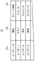
- FIG. 2 is a functional block diagram illustrating a schematic configuration of a first image forming apparatus and a management server illustrated in FIG. 1. It is an example of registration of the account information shown in FIG.
- FIG. 2 is a functional block diagram illustrating a schematic configuration of a second image forming apparatus illustrated in FIG. 1.
- 3 is a flowchart showing a flow of charge processing and refund processing of the first image forming apparatus shown in FIG. 2. It is a display example of the initial screen for users. It is a display example of a deposit / withdrawal screen. It is a display example of a deposit screen. It is a display example of a refund screen.
- FIG. 3 is a flowchart showing a flow of charging processing of the first image forming apparatus and the second image forming apparatus shown in FIG.
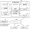
- the charging system 600 includes a first image forming apparatus 100 to which a money input apparatus 101 is attached, a second image forming apparatus 200 to which no money input apparatus 101 is attached, A management server 300 and a user terminal 400 are provided.
- the first image forming apparatus 100, the second image forming apparatus 200, the management server 300, and the user terminal 400 are connected via a network 500.
- the money insertion device 101 includes an insertion port 101 a into which money such as coins and banknotes is inserted, and a refund port 101 b for returning money, and is controlled by the first image forming apparatus 100.
- the first image forming apparatus 100 is connected to the network 500 via the money input apparatus 101.
- One or more of the first image forming apparatus 100, the second image forming apparatus 200, and the user terminal 400 may be connected to the network 500.
- FIG. 2 is a functional block diagram showing a schematic configuration of the first image forming apparatus 100, the money input apparatus 101, and the management server 300.
- the first image forming apparatus 100 is a copying machine or a multifunction machine using an electrophotographic method, and includes an operation unit 11, a document reading unit 12, a storage unit 13, an image processing unit 14, a printing unit 15, A communication unit 16 and a control unit 17 are provided.
- the operation unit 11 includes a touch panel and operation buttons.
- the touch panel is provided with a transparent pressure-sensitive sensor on the surface of a display unit that displays various operation keys and image formation status, and functions as a display unit and an input unit.
- the touch panel detects a touch operation on the display surface and outputs a signal corresponding to the position where the touch operation is detected, thereby accepting an operation on the operation key displayed on the display unit.
- the operation buttons are a numeric keypad for inputting a numerical value such as the number of prints, a reset key for inputting an instruction to initialize setting information, a stop key for stopping a copying operation, and an output instruction for starting a printing operation.
- Various operation keys such as a start key for inputting.
- the document reading unit 12 emits light to a document fed by a document feeder (not shown) or a document placed on a platen glass by a user, and receives reflected light or the like to form a document image. It is a scanner that reads.
- the storage unit 13 is a storage unit such as a semiconductor memory or an HDD (Hard Disk Drive), image data received via the communication unit 16, document data including a character string, and image data read by the document reading unit 12. Are storage means for storing print data. Further, the storage unit 13 stores a fee table 131 in which the usage fee of the own device is set.
- the fee table 131 may be provided separately with a fee table for professors, students and other on-campus personnel, and a fee table for off-campus personnel who log in as a guest, and the respective fee settings may be different.
- the image processing unit 14 is a unit that performs predetermined image processing on the image data.
- image improvement processing such as enlargement / reduction processing, density adjustment, and gradation adjustment is performed.
- the printing unit 15 is a printing unit that prints the print data stored in the storage unit 13 on a recording sheet.
- the printing unit 15 forms a latent image on the surface of the photosensitive drum based on the image data read from the storage unit 13, performs image formation using the latent image as a toner image with toner, and records from the photosensitive drum.
- the toner image is transferred onto the paper, and the toner image is fixed onto the recording paper and discharged.
- the printing unit 15 has a function of forming toner images using toners such as cyan, magenta, yellow, and black, respectively. By superimposing these toner images and fixing them on a recording sheet, full-color printing can be performed. It corresponds.
- the communication unit 16 is connected to the money input device 101 via a LAN (Local Area Network) cable, and has a function of transmitting and receiving various data to and from the money input device 101. Further, the communication unit 16 has a function of transmitting / receiving various data to / from the management server 300, the user terminal 400, and the second image forming apparatus 200 via the money input device 101 and the network 500.
- LAN Local Area Network
- the control unit 17 is connected to the operation unit 11, the document reading unit 12, the storage unit 13, the image processing unit 14, the printing unit 15, and the communication unit 16, respectively.
- the control unit 17 is an information processing unit such as a microcomputer including a CPU (Central Processing Unit), a ROM (Read Only Memory), a RAM (Random Access Memory), and the like.
- the ROM stores a control program for controlling the operation of the first image forming apparatus 100.
- the control program may be recorded on a computer-readable recording medium and provided to the control unit 17.
- the control unit 17 reads the control program stored in the ROM, develops the control program in the RAM, and executes it to control the entire apparatus. Further, the control unit 17 functions as an authentication unit 171, a job processing unit 172, an accounting processing unit 173, a charge request unit 174, and a refund request unit 175.
- the authentication unit 171 performs user authentication by collating user information such as a user ID (account) and a password input via the operation unit 11 with authentication information stored in advance.
- User information may be input using an IC card such as a student ID card possessed by the user.
- the authentication unit 171 places the first image forming apparatus 100 in the login state, and displays an initial user screen (see FIG. 6) G60 associated with the authenticated user on the operation unit 11. To display.
- the authentication information may be stored in each of the first image forming apparatus 100 and the second image forming apparatus 200, or may be stored in the management server 300.
- the authentication unit 171 may perform user authentication to determine whether the user matches the user account of the account information 32 stored in the server storage unit 31.
- the job processing unit 172 has a function of receiving a job to be executed via the operation unit 11 and executing the job only when the charging processing unit 173 permits execution of the job.
- the charging processing unit 173 calculates a charging amount based on the job accepted by the job processing unit 172 with reference to the fee table 131 and displays the calculated amount on the operation unit 11. Then, the charging processing unit 173 permits the execution of the job on condition that the user's charge (payment) balance 32c (see FIG. 3) in the account information 32 is equal to or more than the charging amount. If the user's charge balance 32c is less than the charge amount, the execution of the job is prohibited and a message indicating that the charge balance 32c is insufficient is displayed on the operation unit 11 to prompt the user account to be charged. In addition, the charging processing unit 173 transmits a charging processing request for subtracting the charging amount from the user's charge balance 32c to the management server 300 after the job is executed.
- the charge request unit 174 has a function of controlling the money input device 101 and receiving a charge to the user account. Specifically, the charge request unit 174 receives the deposit by the money input device 101, and transmits a charge request for charging the user account with the deposit amount as a charge amount to the management server 300 by the communication unit 16.
- Refund request unit 175 has a function of controlling money input device 101 to refund money in charge balance 32c. Specifically, the refund request unit 175 causes the communication unit 16 to issue a refund processing request for causing the money input device 101 to refund money in the charge balance 32c of the login user and subtracting the return amount from the charge balance 32c of the login user. To 300.
- the money input device 101 includes a payment detection unit 102, a refund unit 103, a communication unit 104, and a money control unit 105, and is controlled by the first image forming apparatus 100.
- the deposit detection unit 102 has a function of detecting the amount of money inserted into the insertion port 101a.
- the user can insert coins and bills into the insertion slot 101 a provided in the money insertion apparatus 101.
- the refund unit 103 has a function of returning money from the refund port 101b.
- the communication unit 104 is connected to the first image forming apparatus 100 via a LAN cable and has a function of transmitting / receiving various data to / from the first image forming apparatus 100.
- the communication unit 104 has a function of transmitting / receiving various data to / from the user terminal 400, the management server 300, and the second image forming apparatus 200 via the network 500 by wired or wireless communication.
- the communication unit 104 transmits various data transmitted from the first image forming apparatus 100 to the user terminal 400, the management server 300, and the second image forming apparatus 200 via the network 500 under the control of the first image forming apparatus 100.
- it functions as a router that transmits various data received from the user terminal 400, the management server 300, and the second image forming apparatus 200 via the network 500 to the first image forming apparatus 100.
- the communication unit 16 of the first image forming apparatus 100 and the communication unit 104 of the money input apparatus 101 are connected by the LAN cable, and the money input apparatus 101 is connected by USB to the first image forming apparatus 100.
- the first image forming apparatus 100 and the money input apparatus 101 can be managed by one IP (Internet Protocol) address.
- the money control unit 105 is an information processing unit such as a microcomputer including a CPU, a ROM, a RAM, and the like.
- the ROM stores a control program for controlling the operation of the money input device 101.
- the control program may be recorded on a computer-readable recording medium and provided to the money control unit 105.
- the money control unit 105 reads the control program stored in the ROM, develops the control program in the RAM, and executes the control program, thereby controlling the entire apparatus according to the control from the first image forming apparatus 100.
- the management server 300 includes a server storage unit 31, a server communication unit 33, and a server control unit 34.
- the server storage unit 31 is a storage means such as a semiconductor memory or an HDD, and stores account information 32 as shown in FIG.
- the account information 32 registers users who can use the first image forming apparatus 100 and the second image forming apparatus 200, and stores a user ID 32a, an attribute 32b, and a charge balance 32c in association with each other.
- the attribute 32b includes guest, student, and professor. Guests are outside the university and students and professors are inside the university.
- the charge balance 32c is a so-called credit, and indicates a deposit amount deposited in advance. By making a payment in association with the user account, the user can reflect the deposit amount in the charge balance 32c, and can be used for payment of a charge amount when using the first image forming apparatus 100 and the second image forming apparatus 200. can do.
- the server communication unit 33 has a function of transmitting / receiving various data to / from each of the first image forming apparatus 100, the second image forming apparatus 200, and the user terminal 400 via the network 500 by wired or wireless communication.
- the server control unit 34 is an information processing unit such as a microcomputer including a CPU, a ROM, a RAM, and the like.
- the ROM stores a control program for controlling the operation of the management server 300.
- the control program may be recorded on a computer-readable recording medium and provided to the server control unit 34.
- the server control unit 34 reads the control program stored in the ROM, expands the control program in the RAM, and executes it to control the entire server.
- the server control unit 34 functions as a balance management unit 35 that manages the charge balance 32c of each user registered in the account information 32.
- the balance management unit 35 has a function of updating the charge balance 32c of each user in the account information 32 based on the charge request, refund processing request, and billing processing request received by the server communication unit 33.
- FIG. 4 is a functional block diagram showing a schematic configuration of the second image forming apparatus 200.
- the second image forming apparatus 200 is a copying machine, a multifunction machine, or the like, and includes an operation unit 11, a document reading unit 12, a storage unit 13, an image processing unit 14, a printing unit 15, a communication unit 206, and a control. Part 207.
- the second image forming apparatus 200 has the same configuration as that of the first image forming apparatus 100 except that the money input device 101 is not attached. Therefore, here, the communication unit 206 and the control unit 207 in which the second image forming apparatus 200 is different from the first image forming apparatus 100 will be described, and other description will be omitted.
- the communication unit 206 of the second image forming apparatus 200 has a function of transmitting / receiving various data to / from the management server 300, the user terminal 400, and the first image forming apparatus 100 via the network 500 by wired or wireless communication. Have.
- the control unit 207 of the second image forming apparatus 200 is connected to the operation unit 11, the document reading unit 12, the storage unit 13, the image processing unit 14, the printing unit 15, and the communication unit 206, respectively.
- the control unit 207 is an information processing unit such as a microcomputer including a CPU, a ROM, a RAM, and the like.
- a control program for controlling the operation of the second image forming apparatus 200 is stored in the ROM.
- the control program may be recorded on a computer-readable recording medium and provided to the control unit 207.
- the control unit 207 reads the control program stored in the ROM, develops the control program in the RAM, and executes it to control the entire apparatus.
- the control unit 207 functions as an authentication unit 171, a job processing unit 172, and a charging processing unit 173.
- the control unit 207 of the second image forming apparatus 200 is different from the control unit 17 of the image forming apparatus of the first image forming apparatus 100 in that the charge request unit 174 and the refund request unit 175 are not provided. Since they are the same, description thereof is omitted.
- the user terminal 400 is a personal computer, a smartphone, or the like, and is connected to the first image forming apparatus 100, the second image forming apparatus 200, and the management server 300 via the network 500.
- the user terminal 400 can associate user information with image data or document data to be printed and transmit the user information to the first image forming apparatus 100, the second image forming apparatus 200, and the management server 300 via the network 500.
- the control unit 17 of the first image forming apparatus 100 functions as the authentication unit 171 and the input user information is stored in advance. User authentication is performed by checking against the authentication information. If the user authentication is successful, the authentication unit 171 places the first image forming apparatus 100 in a login state (step s11).
- the authentication unit 171 obtains information associated with the user (for example, the charge balance 32c, the print job, etc.) from the management server 300 and the like, and displays the user initial screen G60 shown in FIG. 6 (step s12). ).
- the user initial screen G60 displays a user ID 32a, a user charge balance 32c, and various operation keys B61.
- the operation key B61 includes a plurality of image forming function keys B61a for setting various image forming functions such as a copy function, a scan function, and a print function, a deposit / withdrawal key B61b for instructing deposit / withdrawal for a user account, and the like. Is provided.
- the control unit 17 displays the deposit / withdrawal screen G70 shown in FIG. On the deposit / withdrawal screen G70, a charge key B71 for instructing charging to the user account and a refund key B72 for instructing refund from the user account are displayed.
- the control unit 17 determines that charging has been instructed (Yes in step s13), and functions as the charge requesting unit 174.
- the charge request unit 174 displays the deposit screen G80 shown in FIG. 8 on the operation unit 11, and controls the money input device 101 to accept the deposit (step s14).
- the user's charge balance 32c the total amount of deposits detected by the deposit detection unit 102 of the depositing device 101 (total deposit amount A81), and “Please insert coins. Please press the key. "Message and an OK key B81 for instructing the completion of payment are displayed.
- the charge request unit 174 determines that the deposit is not completed (No in step s15), and subsequently accepts the deposit by the money input device 101. Each time the user inserts money into the money input device 101, the amount of money received is detected by the money receiving detection unit 102, and the charge request unit 174 sequentially acquires the amount of money detected by the money receiving detection unit 102, and the money receiving screen G80 The total deposit amount A81 is updated.
- the charge request unit 174 determines that the payment is completed (Yes in step s15). Subsequently, the charge request unit 174 terminates the receipt of money received by the money input device 101, and sends a charge request for charging the user account with the total amount A81 received by the money input device 101 as a charge amount. It transmits to the balance management part 35 via the communication part 104 and the network 500 (step s16). Subsequently, the credit processing unit waits until a completion notification is received from the balance management unit 35 (No in step s17 and step s17).
- the balance management unit 35 of the management server 300 that has received the charge request adds and updates the charge amount requested by the charge request to the user's charge balance 32c.
- the charge balance 32c is updated from 50.00 euro to 55.00 euro.
- the balance management unit 35 transmits a completion notification indicating that the processing is completed to the first image forming apparatus 100 via the server communication unit 33.
- the charge request unit 174 receives a completion notification from the balance management unit 35 (step s17), the process ends. Thereby, the user can easily charge a user account with a desired amount using the money input device 101.
- the control unit 17 functions as a refund request unit 175, and displays a refund screen G90 shown in FIG.
- the refund screen G90 the user's charge balance 32c, a message “Please press the OK button when paying out credits”, and an OK key B91 are displayed.
- the refund request unit 175 determines that a refund has been instructed (Yes in step s18), and controls the money input device 101 to refund the money in the user's charge balance 32c. (Step s19). Thereby, the money of the user's charge balance 32c is returned from the money input device 101.
- the refund amount may be the amount specified by the user in the charge balance 32c or the same amount as the charge balance 32c.
- the refund request unit 175 transmits a refund processing request for subtracting the refund amount returned from the money input device 101 from the charge balance 32c of the user to the balance management unit 35 via the communication unit 16, the communication unit 104, and the network 500.
- the system waits until a completion notification is received from the balance management unit 35 (No in Step s17 and Step s17).
- the balance management unit 35 that has received the refund processing request updates the refund amount by subtracting it from the user's charge balance 32c, and transmits a completion notification indicating that the processing is completed to the first image forming apparatus 100 by the server communication unit 33. .
- the refund request unit 175 receives a completion notification from the balance management unit 35 (Yes in step s17), the process ends.
- the user can easily receive a refund of the charge balance 32c using the money input device 101. If neither charge nor refund is instructed (No in step s18), the process ends. In addition, before the refund amount is refunded from the money input device 101, the refund request unit 175 transmits a refund processing request to the balance management unit 35, and after the completion notification is received, the money input device 101 returns the return amount. May be.
- step s31 and step s32 is the same as step s11 and step s12 of the flowchart shown in FIG.
- the authentication unit 171 performs user authentication by comparing user information input by the user via the operation unit 11 with authentication information stored in advance. When the user authentication is successful, the authentication unit 171 sets the image forming apparatus to the login state. (Step s31). Subsequently, the authentication unit 171 displays the user initial screen G60 shown in FIG. 6 associated with the user who has been successfully authenticated on the operation unit 11 (step s32). However, the user initial screen G60 displayed when the second image forming apparatus 200 enters the login state does not include the deposit / withdrawal key B61b. This is because the second image forming apparatus 200 is not provided with the money input device 101.
- a function setting screen corresponding to the operated image forming function key B61a is displayed on the operation unit 11, and various settings such as a copy function, a scan function, a facsimile function, and a print function are performed.
- various print settings such as black and white printing, full color printing, the number of printed sheets, duplex printing, and aggregate printing can be performed.
- the job processing unit 172 receives a job to be executed, such as a copy job, a scan job, or a print job, based on the setting contents set via the function setting screen (step s33).
- the billing processing unit 173 refers to the fee table 131 and calculates the billing amount based on the job accepted by the job processing unit 172 (step s34). Subsequently, the charge processing unit 173 compares the calculated charge amount with the user's charge balance 32c, and determines whether or not the charge balance 32c is equal to or greater than the charge amount (step s35). The charge processing unit 173 may acquire and compare the user's charge balance 32c stored in the account information 32 after calculating the charge amount, or may compare with the user's charge balance 32c acquired when the user logs in. May be.
- step s35 If the charge balance 32c is equal to or greater than the charge amount (Yes in step s35), the charge processing unit 173 permits execution of the job (step s36). Subsequently, when the user instructs execution through the operation unit 11 (Yes in step s37), the job processing unit 172 executes the job (step s38). As a result, various image forming operations such as copying, scanning, and printing are executed.
- the billing processing unit 173 transmits a billing processing request for subtracting the billing amount from the charge balance 32c of the user to the balance management unit 35 through the communication unit 16 or the communication unit 206 (step s39), and the balance management unit 35 notifies the completion. Is received by the communication unit 16 or the communication unit 206 (No in step s17 and step s17).
- the balance management unit 35 that has received the charge processing request updates the requested charge amount by subtracting it from the user's charge balance 32c, and transmits a completion notification. That is, the balance management unit 35 permits payment of the charge amount in the charge balance 32c associated with the same user account not only for the first image forming apparatus but also for the second image forming apparatus.
- the completion notification is received (Yes in step s17)
- the billing processing unit 173 ends this process.
- step s35 the charge processing unit 173 prohibits the execution of the job (step s40) and notifies the operation unit 11 that the charge balance 32c is insufficient. This is displayed (step s41), and this process is terminated.
- the charging system 600 includes a plurality of image forming units each including the charging processing unit 173 that permits the execution of a job on condition that the charging amount to be charged is paid based on the job to be executed.
- the charging system 600 includes an apparatus and a management server 300 connected via a network 500.
- the plurality of image forming apparatuses includes a first image forming apparatus 100 provided with a money input apparatus 101, and a money input apparatus 101.
- the first image forming apparatus 100 includes a second image forming apparatus 200 that is not provided with a charge request, and the first image forming apparatus 100 transmits to the management server 300 a charge request for charging the deposit amount received by the money input apparatus 101 as a charge amount.
- the management server 300 includes a unit 174 based on the charge request transmitted from the charge request unit 174.
- the user account to be charged via the money input device 101, the user can be charged individually, and the university side does not have to prepare human resources to perform the charge procedure, etc., reducing labor costs it can.
- the charging processing unit 173 of the first image forming apparatus 100 may receive money by controlling the money input device 101 when the charge balance 32c is insufficient. Then, the billing processing unit 173 cancels the prohibition of job execution and permits the execution when the sum of the deposit amount deposited in the money input device 101 and the charge balance 32c exceeds the billing amount. May be. Thereby, the user can pay the bill amount by using the charge balance 32c and cash together. In addition, when change is generated when the charge amount is paid from the total amount, the charge processing unit 173 may return the change (the difference between the total amount and the charge amount) by the money input device 101, or a charge request The unit 174 may transmit a charge request for charging the user account as a change amount to the management server 300. In addition, the change process may be selected by the user via the operation unit 11.
- the second image forming apparatus 200 may be provided with a notification unit that notifies the user by sending it to a user's e-mail address or the like. According to this, the user can easily know the location of the chargeable first image forming apparatus 100 and can go to charge. In this case, it is assumed that the storage location information of the first image forming apparatus 100 installed on the premises is stored in the storage unit 13 of the second image forming apparatus 200.
- the user's charge balance 32c is confirmed, and the charge balance 32c is equal to or less than the specific balance.
- the user terminal 400 may be notified to use the first image forming apparatus 100. According to this, when the user with a small charge balance 32c uses the second image forming apparatus 200, it is possible to prevent the user from moving to the first image forming apparatus 100 due to the lack of the charge balance 32c.
- the first image forming apparatus 100 has a Web server function, and the charge requesting unit 174, the refund requesting unit 175, and the accounting processing unit 173 of the first image forming apparatus 100 are connected to a money input device via an API (Application Programming Interface). You may perform control with respect to 101.
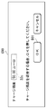
- FIG. The API is provided corresponding to each of the processes that individually divide the general control flow for the money insertion device 101, such as enabling the money insertion device 101, accepting coin insertion, and inquiring the amount of money to be deposited. .
- the charge request unit 174, the refund request unit 175, and the charge processing unit 173 control the money input apparatus 101 using APIs corresponding to the respective processes. In this way, the general control flow for the money input device 101 is divided individually, and the money input device 101 is controlled by using the API corresponding to each of the divided processes.
- the device 101 can be a connection target.
- the server storage unit 31 stores a charge balance 32c to be charged based on the charge request received from the charge request unit 174 in association with the user account, and the first image forming apparatus 100 and the second image forming apparatus 200.
- the billing system 600 according to the present embodiment is installed in a limited area such as a research building, each user can freely make the first image forming apparatus and the second image within the research expenses (budget).
- a forming device may be used.
- the charge balance 32c may be charged in association with a single user account, or may be stored in the server storage unit 31 as the charge balance 32c regardless of the user account.
Landscapes
- Engineering & Computer Science (AREA)
- Business, Economics & Management (AREA)
- Theoretical Computer Science (AREA)
- General Physics & Mathematics (AREA)
- Physics & Mathematics (AREA)
- Strategic Management (AREA)
- Tourism & Hospitality (AREA)
- General Business, Economics & Management (AREA)
- Health & Medical Sciences (AREA)
- Marketing (AREA)
- Primary Health Care (AREA)
- Human Resources & Organizations (AREA)
- General Health & Medical Sciences (AREA)
- Economics (AREA)
- Signal Processing (AREA)
- Multimedia (AREA)
- Accounting & Taxation (AREA)
- Human Computer Interaction (AREA)
- General Engineering & Computer Science (AREA)
- Facsimiles In General (AREA)
- Control Or Security For Electrophotography (AREA)
Abstract
課金可能な画像形成装置を低コストで多数設置する。 複数の画像形成装置は、実行対象とするジョブに基づいて課金する課金額が支払われることを条件にジョブの実行を許可する課金処理部(173)をそれぞれ備え、金銭投入装置(101)が付設された第1画像形成装置(100)と、金銭投入装置(101)が付設されていない第2画像形成装置(200)とを備えている。第1画像形成装置(100)は、金銭投入装置(101)に入金される入金額をチャージ額としてチャージさせるチャージ要求を管理サーバー(300)に送信するチャージ要求部(174)を備え、管理サーバー(300)は、チャージ要求部(174)から送信されたチャージ要求に基づいてチャージされるチャージ残高を記憶するサーバー記憶部(31)と、第1画像形成装置(100)だけでなく第2画像形成装置(200)に対しても、チャージ残高内で課金額の支払いを許可する残高管理部(35)とを備えている。
Description
本発明は、複数の画像形成装置と管理サーバーがネットワークを介して接続された課金システムに関する。
従来、大学等の構内には、画像形成装置が設置されており、教授や学生等が画像形成装置を利用して資料のコピーや提出物の印刷等を行っている。このような画像形成装置の傍らには、コインベンダー等の金銭投入装置が設置されており、画像形成装置の使用料金を徴収している(例えば、特許文献1を参照)。
しかしながら、金銭投入装置は高価であるため、課金可能な画像形成装置を構内に複数設置することができず、順番待ち等が発生して、ユーザーが気軽に画像形成装置を使用することができなかったという問題があった。
本発明は上記課題に鑑みてなされたものであり、課金可能な画像形成装置を低コストで複数設置することができる技術を提供することを目的とする。
本発明の課金システムは、実行対象とするジョブに基づいて課金する課金額が支払われることを条件に前記ジョブの実行を許可する課金処理部をそれぞれ備えた複数の画像形成装置と、管理サーバーとがネットワークを介して接続された課金システムであって、前記複数の画像形成装置は、金銭投入装置が付設された第1画像形成装置と、金銭投入装置が付設されていない第2画像形成装置とを備え、前記第1画像形成装置は、前記金銭投入装置に入金される入金額をチャージ額としてチャージさせるチャージ要求を前記管理サーバーに送信するチャージ要求部を備え、前記管理サーバーは、前記チャージ要求部から送信された前記チャージ要求に基づいてチャージされるチャージ残高を記憶するサーバー記憶部と、前記第1画像形成装置だけでなく前記第2画像形成装置に対しても、前記チャージ残高内で前記課金額の支払いを許可する残高管理部とを備えたことを特徴とする。
本発明によれば、課金可能な画像形成装置を低コストで多数設置することができる。
以下、図を参照して本発明の実施形態を詳細に説明する。なお、以下の実施形態において、同様の機能を示す構成には、同一の符号を付してある。
図1に示すように、本実施の形態の課金システム600は、金銭投入装置101が付設された第1画像形成装置100と、金銭投入装置101が付設されていない第2画像形成装置200と、管理サーバー300と、ユーザー端末400とを備えている。第1画像形成装置100と第2画像形成装置200と管理サーバー300とユーザー端末400とはネットワーク500を介して接続されている。金銭投入装置101は、コインや紙幣等の金銭が投入される投入口101aと、金銭を返却する返金口101bとを備え、第1画像形成装置100によって制御される。なお、第1画像形成装置100は、金銭投入装置101を介してネットワーク500に接続されている。第1画像形成装置100と第2画像形成装置200とユーザー端末400とは、それぞれ1以上がネットワーク500に接続されていれば良い。
図2は、第1画像形成装置100と金銭投入装置101と管理サーバー300の概略構成を示す機能ブロック図である。
第1画像形成装置100は、電子写真方式を利用した複写機や複合機等であり、操作部11と、原稿読取部12と、記憶部13と、画像処理部14と、印刷部15と、通信部16と、制御部17とを備えている。
操作部11は、タッチパネルや操作ボタンを備えている。タッチパネルは、各種操作キーや画像形成状況を表示する表示部の表面に透明の感圧センサーが設けられており、表示手段及び入力手段として機能する。タッチパネルは、表示面へのタッチ操作を検知して、タッチ操作が検知された位置に対応する信号を出力することで、表示部に表示した操作キーへの操作を受け付ける。また、操作ボタンは、印刷枚数等の数値を入力するためのテンキー、設定情報を初期化させる指示を入力するためのリセットキー、複写動作を停止させるためのストップキー、印刷動作を開始させる出力指示を入力するためのスタートキー等の各種操作キーを備えている。
原稿読取部12は、図示しない原稿給紙装置により給紙されてきた原稿や、ユーザーによってプラテンガラスに載置された原稿に対して光を照射し、その反射光等を受光して原稿画像を読み取るスキャナーである。
記憶部13は、半導体メモリーやHDD(Hard Disk Drive)等の記憶手段であり、通信部16を介して受信された画像データや文字列を含む文書データ、原稿読取部12によって読み取られた画像データ等が印刷データとして蓄積される記憶手段である。また、記憶部13には、自装置の使用料金が設定された料金表131が記憶されている。料金表131は、教授や学生等の学内関係者用の料金表と、ゲストとしてログインする学外関係者用の料金表とを別に設け、それぞれの料金設定が異なるようにしてもよい。
画像処理部14は、画像データに対して所定の画像処理を行う手段である。画像処理部14では、例えば、拡大縮小処理や、濃度調整、階調調整等の画像改善処理が行われる。
印刷部15は、記憶部13に記憶された印刷データを記録紙に印刷する印刷手段である。印刷部15は、例えば、記憶部13から読み出した画像データに基づき感光体ドラムの表面に潜像を形成し、トナーによってその潜像をトナー像とする画像形成を行い、その感光体ドラムから記録紙にトナー像を転写させ、そのトナー像を記録紙に定着させて排紙する。また、印刷部15は、シアン、マゼンダ、イエロー、ブラック等のトナーを用いてそれぞれトナー像を形成する機能を有し、これらのトナー像を重ね合わせて記録紙に定着させることで、フルカラー印刷に対応している。
通信部16は、LAN(Local Area Network)ケーブルによって、金銭投入装置101に接続されており、金銭投入装置101と各種データを送受信する機能を有する。また、通信部16は、金銭投入装置101及びネットワーク500を介して、管理サーバー300やユーザー端末400、第2画像形成装置200との間で各種データをそれぞれ送受信する機能を有する。
制御部17は、操作部11、原稿読取部12、記憶部13、画像処理部14、印刷部15及び通信部16にそれぞれ接続されている。制御部17は、CPU(Central Processing Unit)、ROM(Read Only Memory)、RAM(Random Access Memory)等を備えたマイクロコンピューター等の情報処理部である。ROMには第1画像形成装置100の動作制御を行うための制御プログラムが記憶されている。制御プログラムは、コンピューター読み取り可能な記録媒体に記録されて制御部17に提供されてもよい。制御部17は、ROMに記憶されている制御プログラムを読み出し、制御プログラムをRAMに展開させて実行することで、装置全体の制御を行う。また、制御部17は、認証部171、ジョブ処理部172、課金処理部173、チャージ要求部174、返金要求部175として機能する。
認証部171は、操作部11を介して入力されるユーザーID(アカウント)やパスワード等のユーザー情報を、予め記憶された認証情報と照合することで、ユーザー認証を行う。ユーザーが所持する学生証等のICカードを用いてユーザー情報が入力されてもよい。入力されたユーザー情報が認証情報に合致すると、認証部171は、第1画像形成装置100をログイン状態とし、認証したユーザーに関連付けられたユーザー用初期画面(図6を参照)G60を操作部11に表示する。認証情報は、第1画像形成装置100や第2画像形成装置200にそれぞれ記憶されてもよいし、管理サーバー300に記憶されてもよい。例えば、認証部171は、サーバー記憶部31に記憶されたアカウント情報32のユーザーアカウントに合致するユーザーであるかユーザー認証を行ってもよい。
ジョブ処理部172は、操作部11を介して実行対象とするジョブを受け付け、課金処理部173によりこのジョブの実行が許可された場合に限ってジョブを実行する機能を有する。
課金処理部173は、料金表131を参照して、ジョブ処理部172によって受け付けられたジョブに基づいて課金額を算出し、操作部11に表示する。そして、課金処理部173は、アカウント情報32におけるユーザーのチャージ(入金)残高32c(図3を参照)が課金額以上あることを条件に、ジョブの実行を許可する。ユーザーのチャージ残高32cが課金額未満である場合には、ジョブの実行を禁止して、チャージ残高32cが足りない旨のメッセージを操作部11に表示し、ユーザーアカウントへのチャージを促す。また、課金処理部173は、ジョブの実行後に課金額をユーザーのチャージ残高32cから差し引く課金処理要求を管理サーバー300に送信する。
チャージ要求部174は、金銭投入装置101を制御して、ユーザーアカウントへのチャージを受け付ける機能を有する。具体的には、チャージ要求部174は、金銭投入装置101により入金を受け付け、入金額をチャージ額としてユーザーアカウントにチャージさせるチャージ要求を通信部16により管理サーバー300に送信する。
返金要求部175は、金銭投入装置101を制御して、チャージ残高32c内の金銭を返金する機能を有する。具体的には、返金要求部175は、ログインユーザーのチャージ残高32c内の金銭を金銭投入装置101から返金させ、返金額をログインユーザーのチャージ残高32cから差し引く返金処理要求を通信部16により管理サーバー300に送信する。
次に、金銭投入装置101の概略構成を説明する。金銭投入装置101は、入金検知部102と、返金部103と、通信部104と、金銭制御部105とを備えており、第1画像形成装置100によって制御される。
入金検知部102は、投入口101aに投入された金銭の金額を検知する機能を有する。ユーザーは、金銭投入装置101に設けられた投入口101aにコインや紙幣を投入することができる。
返金部103は、返金口101bから金銭を返金する機能を有する。
通信部104は、LANケーブルによって第1画像形成装置100と接続しており、第1画像形成装置100と各種データを送受信する機能を有する。また、通信部104は、有線や無線の通信によってネットワーク500を介してユーザー端末400、管理サーバー300及び第2画像形成装置200のそれぞれと各種データを送受信する機能を有する。
通信部104は、第1画像形成装置100の制御により、第1画像形成装置100から送信される各種データをネットワーク500を介してユーザー端末400や管理サーバー300、第2画像形成装置200に送信すると共に、ネットワーク500を介してユーザー端末400や管理サーバー300、第2画像形成装置200から受信する各種データを第1画像形成装置100に送信するルーターとして機能する。このように、第1画像形成装置100の通信部16と金銭投入装置101の通信部104とをLANケーブルによって接続し、第1画像形成装置100により金銭投入装置101をUSB接続されたデバイスのように制御することで、第1画像形成装置100と金銭投入装置101とを1つのIP(Internet Protocol)アドレスで管理することができる。
金銭制御部105は、CPU、ROM、RAM等を備えたマイクロコンピューター等の情報処理部である。ROMには金銭投入装置101の動作制御を行うための制御プログラムが記憶されている。制御プログラムは、コンピューター読み取り可能な記録媒体に記録されて金銭制御部105に提供されてもよい。金銭制御部105は、ROMに記憶されている制御プログラムを読み出し、制御プログラムをRAMに展開させて実行することで、第1画像形成装置100からの制御に従って装置全体の制御を行う。
次に、管理サーバー300の概略構成を説明する。管理サーバー300は、サーバー記憶部31と、サーバー通信部33と、サーバー制御部34とを備えている。
サーバー記憶部31は、半導体メモリーやHDD等の記憶手段であり、図3に示すようなアカウント情報32を記憶する。アカウント情報32は、第1画像形成装置100及び第2画像形成装置200を使用可能なユーザーを登録したものであり、ユーザーID32aと、属性32bと、チャージ残高32cとが関連付けて記憶されている。属性32bには、ゲスト、学生、教授がある。ゲストが学外関係者であり、学生及び教授が学内関係者である。チャージ残高32cは、いわゆるクレジットと呼ばれるものであり、予め入金された入金額を示す。ユーザーは、ユーザーアカウントに関連付けて入金することで、入金額をチャージ残高32cに反映させることができ、第1画像形成装置100及び第2画像形成装置200を使用する際の課金額の支払いに利用することができる。
サーバー通信部33は、有線や無線の通信によってネットワーク500を介して第1画像形成装置100、第2画像形成装置200及びユーザー端末400のそれぞれとの間で、各種データを送受信する機能を有する。
サーバー制御部34は、CPU、ROM、RAM等を備えたマイクロコンピューター等の情報処理部である。ROMには管理サーバー300の動作制御を行うための制御プログラムが記憶されている。制御プログラムは、コンピューター読み取り可能な記録媒体に記録されてサーバー制御部34に提供されてもよい。サーバー制御部34は、ROMに記憶されている制御プログラムを読み出し、制御プログラムをRAMに展開させて実行することで、サーバー全体の制御を行う。また、サーバー制御部34は、アカウント情報32に登録されている各ユーザーのチャージ残高32cを管理する残高管理部35として機能する。
残高管理部35は、サーバー通信部33により受信するチャージ要求、返金処理要求、課金処理要求に基づいて、アカウント情報32の各ユーザーのチャージ残高32cを更新する機能を有する。
図4は、第2画像形成装置200の概略構成を示す機能ブロック図である。第2画像形成装置200は、複写機や複合機等であり、操作部11と、原稿読取部12と、記憶部13と、画像処理部14と、印刷部15と、通信部206と、制御部207とを備えている。第2画像形成装置200は、金銭投入装置101が付設されていないこと以外は、第1画像形成装置100と同様の構成である。そのため、ここでは第2画像形成装置200が第1画像形成装置100と異なる通信部206と制御部207を説明し、他の説明を省略する。
第2画像形成装置200の通信部206は、有線や無線の通信によってネットワーク500を介して管理サーバー300やユーザー端末400、第1画像形成装置100との間でそれぞれ各種データの送受信を行う機能を有する。
第2画像形成装置200の制御部207は、操作部11、原稿読取部12、記憶部13、画像処理部14、印刷部15及び通信部206にそれぞれ接続されている。制御部207は、CPU、ROM、RAM等を備えたマイクロコンピューター等の情報処理部である。ROMには第2画像形成装置200の動作制御を行うための制御プログラムが記憶されている。制御プログラムは、コンピューター読み取り可能な記録媒体に記録されて制御部207に提供されてもよい。制御部207は、ROMに記憶されている制御プログラムを読み出し、制御プログラムをRAMに展開させて実行することで、装置全体の制御を行う。また、制御部207は、認証部171、ジョブ処理部172、課金処理部173として機能する。第2画像形成装置200の制御部207が第1画像形成装置100の画像形成装置の制御部17と異なる点は、チャージ要求部174及び返金要求部175を備えていない点であり、他の構成は同じであるため、説明を省略する。
次に、ユーザー端末400は、パーソナルコンピューターやスマートフォン等であり、ネットワーク500を介して第1画像形成装置100と第2画像形成装置200と管理サーバー300とにそれぞれ接続している。ユーザー端末400は、印刷対象の画像データや文書データにユーザー情報を関連付けて、ネットワーク500経由で第1画像形成装置100や第2画像形成装置200、管理サーバー300に送信することができる。
次に、図5を参照して、第1画像形成装置100のチャージ処理及び返金処理の流れを説明する。
ユーザーが、操作部11を介してユーザー情報を入力し、ログインの実行を指示すると、第1画像形成装置100の制御部17は、認証部171として機能し、入力されたユーザー情報を予め記憶された認証情報と照合することで、ユーザー認証を行う。ユーザー認証に成功すると、認証部171は、第1画像形成装置100をログイン状態にする(ステップs11)。
つづいて、認証部171は、このユーザーに関連付けられた情報(例えば、チャージ残高32cやプリントジョブ等)を管理サーバー300等から取得し、図6に示すユーザー用初期画面G60を表示する(ステップs12)。
ユーザー用初期画面G60には、ユーザーID32aと、ユーザーのチャージ残高32cと、各種の操作キーB61とが表示される。操作キーB61には、コピー機能、スキャン機能、プリント機能等の各種画像形成機能を設定するための複数の画像形成機能キーB61aと、ユーザーアカウントに対する入出金を指示するための入出金キーB61b等が設けられている。
入出金キーB61bが押されると、制御部17は、図7に示す入出金画面G70を操作部11に表示する。入出金画面G70には、ユーザーアカウントへのチャージを指示するためのチャージキーB71と、ユーザーアカウントからの返金を指示するための返金キーB72とが表示される。
チャージキーB71が押された場合、制御部17は、チャージを指示されたと判断して(ステップs13でYes)、チャージ要求部174として機能する。チャージ要求部174は、図8に示す入金画面G80を操作部11に表示すると共に、金銭投入装置101を制御して入金を受け付ける(ステップs14)。入金画面G80には、ユーザーのチャージ残高32cと、金銭投入装置101の入金検知部102により検知された入金額の合計額(合計入金額A81)と、「コインを投入してください。終わったらOKキーを押してください。」という旨のメッセージと、入金完了を指示するためのOKキーB81とが表示される。
OKキーB81が押されない間、チャージ要求部174は、入金完了していないと判断し(ステップs15でNo)、引き続き、金銭投入装置101により入金を受け付ける。ユーザーが金銭投入装置101に金銭を投入する度に、その入金額が入金検知部102により検知され、チャージ要求部174は、入金検知部102が検知した入金額を逐次取得して、入金画面G80内の合計入金額A81を更新する。
OKキーB81が押されると、チャージ要求部174は、入金完了と判断する(ステップs15でYes)。つづいて、チャージ要求部174は、金銭投入装置101による入金受付を終了して、金銭投入装置101に入金された合計入金額A81をチャージ額として、ユーザーアカウントにチャージさせるチャージ要求を通信部16、通信部104及びネットワーク500経由で残高管理部35に送信する(ステップs16)。つづいて、クレジット処理部は、残高管理部35から完了通知を受信するまで待機する(ステップs17、ステップs17でNo)。
チャージ要求を受信した管理サーバー300の残高管理部35は、チャージ要求により要求されたチャージ額をユーザーのチャージ残高32cに加算して更新する。これにより、例えば図8に示すように、合計入金額A81として5ユーロがチャージされた場合、チャージ残高32cが50.00ユーロから55.00ユーロに更新される。つづいて、残高管理部35は、処理が完了したことを示す完了通知をサーバー通信部33により第1画像形成装置100に送信する。チャージ要求部174は、残高管理部35から完了通知を受信すると(ステップs17)、本処理を終了する。これにより、ユーザーは、金銭投入装置101を利用して簡単に所望の金額をユーザーアカウントにチャージすることができる。
一方、図7に示す返金キーB72が押された場合、制御部17は返金要求部175として機能し、図9に示す返金画面G90を操作部11に表示する。返金画面G90には、ユーザーのチャージ残高32cと、「クレジットを払い出す場合、OKボタンを押してください。」という旨のメッセージと、OKキーB91とが表示される。
OKキーB91が押されると、返金要求部175は、返金を指示されたと判断して(ステップs18でYes)、金銭投入装置101に対してユーザーのチャージ残高32cの金銭を返金するように制御する(ステップs19)。これにより、金銭投入装置101からユーザーのチャージ残高32cの金銭が返金される。なお、返金額は、チャージ残高32c内でユーザーが指定した金額でもよいし、チャージ残高32cと同一額であってもよい。
つづいて、返金要求部175は、金銭投入装置101から返金させた返金額をユーザーのチャージ残高32cから差し引く返金処理要求を通信部16、通信部104及びネットワーク500経由で残高管理部35に送信し(ステップs20)、残高管理部35から完了通知を受信するまで待機する(ステップs17、ステップs17でNo)。返金処理要求を受信した残高管理部35は、返金額をユーザーのチャージ残高32cから差し引いて更新し、処理が完了したことを示す完了通知をサーバー通信部33により第1画像形成装置100に送信する。返金要求部175は、残高管理部35からの完了通知を受信すると(ステップs17でYes)、本処理を終了する。これにより、ユーザーは、金銭投入装置101を利用して手軽にチャージ残高32cの返金を受けることができる。なお、チャージも返金も指示されなかった場合(ステップs18でNo)、本処理は終了する。また、金銭投入装置101から返金額を返金させる前に、返金要求部175により返金額の返金処理要求を残高管理部35に送信し、完了通知の受信後に金銭投入装置101から返金額を返金させてもよい。
次に、図10を参照して、第1画像形成装置100及び第2画像形成装置200における課金処理の流れを説明する。なお、ステップs31及びステップs32の処理は、図5に示すフローチャートのステップs11及びステップs12と同じである。
認証部171は、操作部11を介してユーザーにより入力されたユーザー情報を予め記憶された認証情報と照合することでユーザー認証を行い、ユーザー認証に成功した場合に、画像形成装置をログイン状態とする(ステップs31)。つづいて、認証部171は、認証に成功したユーザーに関連付けられた図6に示すユーザー用初期画面G60を操作部11に表示する(ステップs32)。ただし、第2画像形成装置200がログイン状態となった場合に表示されるユーザー用初期画面G60は、入出金キーB61bが設けられていない。第2画像形成装置200は金銭投入装置101が付設されていないからである。
ユーザーが画像形成機能キーB61aを操作すると、操作した画像形成機能キーB61aに対応する機能設定画面が操作部11に表示され、それぞれコピー機能、スキャン機能、ファクシミリ機能、プリント機能等の各種設定を行うことができる。例えば、プリント機能を設定する機能設定画面では、白黒印刷やフルカラー印刷、印刷枚数、両面印刷、集約印刷等の各種印刷設定を行うことができる。ジョブ処理部172は、機能設定画面を介して設定される設定内容に基づいて、コピージョブ、スキャンジョブ、プリントジョブ等の実行対象とするジョブを受け付ける(ステップs33)。
つづいて、課金処理部173は、料金表131を参照し、ジョブ処理部172が受け付けたジョブに基づいて課金額を算出する(ステップs34)。つづいて、課金処理部173は、算出した課金額とユーザーのチャージ残高32cとを比較して、チャージ残高32cが課金額以上あるか否かを判断する(ステップs35)。課金処理部173は、課金額の算出後にアカウント情報32に記憶されたユーザーのチャージ残高32cを取得して比較してもよいし、ユーザーがログインした際に取得したユーザーのチャージ残高32cと比較してもよい。
チャージ残高32cが課金額以上ある場合(ステップs35でYes)、課金処理部173は、ジョブの実行を許可する(ステップs36)。つづいて、操作部11を介してユーザーが実行を指示すると(ステップs37でYes)、ジョブ処理部172は、ジョブを実行する(ステップs38)。これにより、コピー、スキャン、印刷等の各種画像形成動作が実行される。
つづいて、課金処理部173は、課金額をユーザーのチャージ残高32cから差し引く課金処理要求を通信部16又は通信部206により残高管理部35に送信し(ステップs39)、残高管理部35から完了通知を通信部16又は通信部206により受信するまで待機する(ステップs17、ステップs17でNo)。課金処理要求を受信した残高管理部35は、要求された課金額をユーザーのチャージ残高32cから差し引いて更新し、完了通知を送信する。つまり、残高管理部35は、第1画像形成装置だけでなく第2画像形成装置に対しても、同じユーザーアカウントに関連付けられたチャージ残高32c内で課金額の支払いを許可する。完了通知を受信すると(ステップs17でYes)、課金処理部173は、本処理を終了する。
一方、チャージ残高32cが課金額未満である場合(ステップs35でNo)、課金処理部173は、ジョブの実行を禁止し(ステップs40)、チャージ残高32cが不足している旨を操作部11に表示して(ステップs41)、本処理を終了する。
このように、本実施形態の課金システム600は、実行対象とするジョブに基づいて課金する課金額が支払われることを条件にジョブの実行を許可する課金処理部173をそれぞれ備えた複数の画像形成装置と、管理サーバー300とがネットワーク500を介して接続された課金システム600であって、複数の画像形成装置は、金銭投入装置101が付設された第1画像形成装置100と、金銭投入装置101が付設されていない第2画像形成装置200とを備え、第1画像形成装置100は、金銭投入装置101に入金される入金額をチャージ額としてチャージさせるチャージ要求を管理サーバー300に送信するチャージ要求部174を備え、管理サーバー300は、チャージ要求部174から送信されたチャージ要求に基づいてチャージされるチャージ残高32cを記憶するサーバー記憶部31と、第1画像形成装置100だけでなく第2画像形成装置200に対しても、チャージ残高32c内で課金額の支払いを許可する残高管理部35とを備えたことを特徴とする。これにより、金銭投入装置101を付設した第1画像形成装置100だけでなく、金銭投入装置101を付設していない第2画像形成装置200においても、課金が可能となる。そのため、課金可能な画像形成装置を構内に設置しやすくなり、画像形成装置を使用するユーザーによる順番待ちが発生しにくくなるので、ユーザーの利便性を向上させることができる。また、金銭投入装置101を介してユーザーアカウントにチャージできるようにすることで、ユーザーが個人でチャージ可能となり、大学側等がチャージ等の手続きを行う人材を用意せずに済み、人件費を削減できる。
なお、第1画像形成装置100の課金処理部173は、チャージ残高32cが不足している場合、金銭投入装置101を制御して入金を受け付けてもよい。そして、課金処理部173は、金銭投入装置101に入金された入金額とチャージ残高32cとの合算額が課金額以上となった場合に、ジョブの実行の禁止を解除して、実行を許可してもよい。これにより、ユーザーは、チャージ残高32cと現金とを併用して課金額を支払うことができる。なお、合算額から課金額を支払った際に釣り銭が発生した場合、課金処理部173が金銭投入装置101によって釣り銭(合算額と課金額との差分額)を返金させてもよいし、チャージ要求部174が釣り銭をチャージ額としてユーザーアカウントにチャージさせるチャージ要求を管理サーバー300に送信するようにしてもよい。また、いずれの釣り銭処理にするか操作部11を介してユーザーに選択させてもよい。
また、第2画像形成装置200においてチャージ残高32cが不足した場合に、構内の第1画像形成装置100の設置場所を示す一覧や地図を、操作部11に表示したり、印刷部15により印刷したり、ユーザーのメールアドレス等に送信したりすることで通知する通知部を第2画像形成装置200に設けても良い。これによれば、ユーザーは、チャージ可能な第1画像形成装置100の場所を簡単に知ることができ、チャージに行くことができる。なお、この場合、第2画像形成装置200の記憶部13には、構内に設置されている第1画像形成装置100の設置場所情報が記憶されているものとする。また、第1画像形成装置100、第2画像形成装置200、又は管理サーバー300が、ユーザー端末400から送信されるプリントジョブを受け付けた際に、ユーザーのチャージ残高32cを確認し、特定残高以下である場合に、第1画像形成装置100を利用するようにユーザー端末400に通知してもよい。これによれば、チャージ残高32cの少ないユーザーが第2画像形成装置200を利用した際に、チャージ残高32cの不足のため、第1画像形成装置100に移動し直すことを防止できる。
また、第1画像形成装置100はWebサーバー機能を備え、第1画像形成装置100のチャージ要求部174、返金要求部175及び課金処理部173は、API(Application Programming Interface)を介して金銭投入装置101に対する制御を行ってもよい。APIは、金銭投入装置101を有効にする、コイン投入を受け付ける、入金額を問い合わせる等の金銭投入装置101に対する一般的な制御フローを個々に分割したそれぞれの処理に対応してそれぞれ設けられている。チャージ要求部174、返金要求部175及び課金処理部173は、それぞれの処理に対応するAPIを用いて金銭投入装置101を制御する。このように、金銭投入装置101に対する一般的な制御フローを個別に分割し、分割したそれぞれの処理に対応するAPIを用いて金銭投入装置101を制御するように構成することで、様々な金銭投入装置101を接続対象とすることができる。
また、サーバー記憶部31は、チャージ要求部174から受信するチャージ要求に基づいてチャージされるチャージ残高32cをユーザーアカウントに関連付けて記憶しており、第1画像形成装置100及び第2画像形成装置200は、サーバー記憶部31のアカウント情報32に登録されたユーザーアカウントに合致するユーザーであるかユーザー認証を行う認証部171を備えている。そのため、各ユーザーは、第1画像形成装置100にログインした場合だけでなく第2画像形成装置200にログインした場合でも、それぞれのユーザーアカウントに関連付けられたチャージ残高32cに基づいて課金額を支払うことができる。なお、本実施の形態の課金システム600を研究棟のような限定された領域内に設置する場合には、研究費(予算)の中で各ユーザーが自由に第1画像形成装置及び第2画像形成装置を使えるようにしてもよい。この場合、チャージ残高32cは単一のユーザーアカウントに関連付けられてチャージされるようにしてもよいし、ユーザーアカウントに関係なく単にチャージ残高32cとしてサーバー記憶部31に記憶されてもよい。
本発明は上述した実施の形態に限定されるものではなく、本発明の趣旨を逸脱しない範囲で種々様々に変更が可能であることは言うまでもない。
Claims (6)
- 実行対象とするジョブに基づいて課金する課金額が支払われることを条件に前記ジョブの実行を許可する課金処理部をそれぞれ備えた複数の画像形成装置と、管理サーバーとがネットワークを介して接続された課金システムであって、
前記複数の画像形成装置は、
金銭投入装置が付設された第1画像形成装置と、金銭投入装置が付設されていない第2画像形成装置とを備え、
前記第1画像形成装置は、
前記金銭投入装置に入金される入金額をチャージ額としてチャージさせるチャージ要求を前記管理サーバーに送信するチャージ要求部を備え、
前記管理サーバーは、
前記チャージ要求部から送信された前記チャージ要求に基づいてチャージされるチャージ残高を記憶するサーバー記憶部と、
前記第1画像形成装置だけでなく前記第2画像形成装置に対しても、前記チャージ残高内で前記課金額の支払いを許可する残高管理部とを備えた
ことを特徴とする課金システム。 - 前記第1画像形成装置は、
前記金銭投入装置に対して前記チャージ残高内の金銭を返金させるように制御して、返金額を前記チャージ残高から差し引く返金処理要求を前記管理サーバーに送信する返金要求部を備えた
ことを特徴とする請求項1に記載の課金システム。 - 前記課金処理部は、
前記課金額を前記チャージ残高から差し引く課金処理要求を前記管理サーバーに送信し、
前記残高管理部は、
前記課金処理部から送信された前記課金処理要求に基づいて前記課金額を差し引いた残高に前記チャージ残高を更新する
ことを特徴とする請求項1に記載の課金システム。 - 前記第1画像形成装置の課金処理部は、
前記チャージ残高が前記課金額未満である場合に、前記金銭投入装置に対して入金を受け付けるように制御して、前記金銭投入装置に入金された入金額と前記チャージ残高との合算額が前記課金額以上となる場合に、前記ジョブの実行を許可する
ことを特徴とする請求項1に記載の課金システム。 - 前記チャージ要求部は、
前記合算額と前記課金額との差分額をチャージ額とするチャージ要求を前記管理サーバーに送信する
ことを特徴とする請求項4に記載の課金システム。 - 前記第2画像形成装置は、
前記チャージ残高が前記課金額未満である場合に、前記第1画像形成装置の設置場所を通知する通知部を備えた
ことを特徴とする請求項1に記載の課金システム。
Applications Claiming Priority (2)
| Application Number | Priority Date | Filing Date | Title |
|---|---|---|---|
| JP2017069690 | 2017-03-31 | ||
| JP2017-069690 | 2017-03-31 |
Publications (1)
| Publication Number | Publication Date |
|---|---|
| WO2018179933A1 true WO2018179933A1 (ja) | 2018-10-04 |
Family
ID=63675049
Family Applications (1)
| Application Number | Title | Priority Date | Filing Date |
|---|---|---|---|
| PCT/JP2018/004948 Ceased WO2018179933A1 (ja) | 2017-03-31 | 2018-02-14 | 課金システム |
Country Status (1)
| Country | Link |
|---|---|
| WO (1) | WO2018179933A1 (ja) |
Cited By (2)
| Publication number | Priority date | Publication date | Assignee | Title |
|---|---|---|---|---|
| EP3681139A1 (en) * | 2019-01-10 | 2020-07-15 | KYOCERA Document Solutions Inc. | Image forming system |
| JP2023097677A (ja) * | 2021-12-28 | 2023-07-10 | ブラザー工業株式会社 | サーバ、および、コンピュータプログラム |
Citations (3)
| Publication number | Priority date | Publication date | Assignee | Title |
|---|---|---|---|---|
| JP2010000682A (ja) * | 2008-06-20 | 2010-01-07 | Konica Minolta Business Technologies Inc | 画像形成装置 |
| JP2013025566A (ja) * | 2011-07-21 | 2013-02-04 | Fuji Xerox Co Ltd | 認証装置、サービス提供システム、及びプログラム |
| JP2013029956A (ja) * | 2011-07-28 | 2013-02-07 | Fuji Xerox Co Ltd | サービス提供装置、サービス提供システム、及びプログラム |
-
2018
- 2018-02-14 WO PCT/JP2018/004948 patent/WO2018179933A1/ja not_active Ceased
Patent Citations (3)
| Publication number | Priority date | Publication date | Assignee | Title |
|---|---|---|---|---|
| JP2010000682A (ja) * | 2008-06-20 | 2010-01-07 | Konica Minolta Business Technologies Inc | 画像形成装置 |
| JP2013025566A (ja) * | 2011-07-21 | 2013-02-04 | Fuji Xerox Co Ltd | 認証装置、サービス提供システム、及びプログラム |
| JP2013029956A (ja) * | 2011-07-28 | 2013-02-07 | Fuji Xerox Co Ltd | サービス提供装置、サービス提供システム、及びプログラム |
Cited By (3)
| Publication number | Priority date | Publication date | Assignee | Title |
|---|---|---|---|---|
| EP3681139A1 (en) * | 2019-01-10 | 2020-07-15 | KYOCERA Document Solutions Inc. | Image forming system |
| JP2023097677A (ja) * | 2021-12-28 | 2023-07-10 | ブラザー工業株式会社 | サーバ、および、コンピュータプログラム |
| JP7839447B2 (ja) | 2021-12-28 | 2026-04-02 | ブラザー工業株式会社 | サーバ、および、コンピュータプログラム |
Similar Documents
| Publication | Publication Date | Title |
|---|---|---|
| JP6335507B2 (ja) | 画像形成装置、画像形成装置の制御方法、プログラム | |
| JP2018118406A (ja) | ドキュメント印刷システム、画像形成装置およびドキュメント印刷プログラム | |
| US8982382B2 (en) | Image formation apparatus method, and recording medium with extendable auto clear time | |
| JP5929234B2 (ja) | 画像形成システム、サーバ、課金装置、および、プログラム | |
| JP2025184892A (ja) | 画像処理装置 | |
| JP2015001938A (ja) | 画像処理システム、画像処理方法、画像処理装置及びプログラム | |
| JP6620765B2 (ja) | ドキュメント印刷システム、画像形成装置およびドキュメント印刷プログラム | |
| JP2012159663A (ja) | 画像形成装置 | |
| JP2010097314A (ja) | 課金管理システム | |
| JP2018206409A (ja) | 情報処理装置、精算システム、精算方法およびプログラム | |
| JP2021118493A (ja) | 画像形成装置およびチャージシステム | |
| JP5748815B2 (ja) | 画像形成装置及びその制御方法、並びにプログラム | |
| JP2014059768A (ja) | 情報処理装置、精算システム、精算方法およびプログラム | |
| JP6380616B2 (ja) | 情報処理装置、精算システム、精算方法およびプログラム | |
| CN1761917B (zh) | 图像处理方法、图像处理系统、及图像形成装置 | |
| JP7064384B2 (ja) | 情報処理装置、情報処理装置の制御方法、情報処理装置の制御プログラム、および情報処理装置を備える制御システム | |
| JP2006085633A (ja) | 画像形成装置、画像形成システム、及び中継装置 | |
| JP2013076747A (ja) | 画像形成システム、画像形成装置およびコンピュータープログラム | |
| JP2007047853A (ja) | サービス提供装置及びサービス提供方法、並びにコンピュータ・プログラム | |
| JP5117694B2 (ja) | 画像形成装置用自動販売機 | |
| JP2010049145A (ja) | 課金管理システム | |
| JP2014167680A (ja) | 画像処理システム、処理制御方法及び画像処理装置 | |
| JP2009233940A (ja) | 画像形成装置 | |
| JP2013116570A (ja) | 画像形成装置及び画像形成プログラム | |
| JP4368252B2 (ja) | 画像記録装置 |
Legal Events
| Date | Code | Title | Description |
|---|---|---|---|
| 121 | Ep: the epo has been informed by wipo that ep was designated in this application |
Ref document number: 18777494 Country of ref document: EP Kind code of ref document: A1 |
|
| NENP | Non-entry into the national phase |
Ref country code: DE |
|
| 122 | Ep: pct application non-entry in european phase |
Ref document number: 18777494 Country of ref document: EP Kind code of ref document: A1 |
|
| NENP | Non-entry into the national phase |
Ref country code: JP |