WO2018179530A1 - Dispositif automatique de traitement d'échantillon - Google Patents
Dispositif automatique de traitement d'échantillon Download PDFInfo
- Publication number
- WO2018179530A1 WO2018179530A1 PCT/JP2017/036788 JP2017036788W WO2018179530A1 WO 2018179530 A1 WO2018179530 A1 WO 2018179530A1 JP 2017036788 W JP2017036788 W JP 2017036788W WO 2018179530 A1 WO2018179530 A1 WO 2018179530A1
- Authority
- WO
- WIPO (PCT)
- Prior art keywords
- centrifuge
- pump
- sample
- stage
- pipette tip
- Prior art date
Links
Images


Classifications
-
- G—PHYSICS
- G01—MEASURING; TESTING
- G01N—INVESTIGATING OR ANALYSING MATERIALS BY DETERMINING THEIR CHEMICAL OR PHYSICAL PROPERTIES
- G01N35/00—Automatic analysis not limited to methods or materials provided for in any single one of groups G01N1/00 - G01N33/00; Handling materials therefor
-
- G—PHYSICS
- G01—MEASURING; TESTING
- G01N—INVESTIGATING OR ANALYSING MATERIALS BY DETERMINING THEIR CHEMICAL OR PHYSICAL PROPERTIES
- G01N35/00—Automatic analysis not limited to methods or materials provided for in any single one of groups G01N1/00 - G01N33/00; Handling materials therefor
- G01N35/02—Automatic analysis not limited to methods or materials provided for in any single one of groups G01N1/00 - G01N33/00; Handling materials therefor using a plurality of sample containers moved by a conveyor system past one or more treatment or analysis stations
-
- G—PHYSICS
- G01—MEASURING; TESTING
- G01N—INVESTIGATING OR ANALYSING MATERIALS BY DETERMINING THEIR CHEMICAL OR PHYSICAL PROPERTIES
- G01N35/00—Automatic analysis not limited to methods or materials provided for in any single one of groups G01N1/00 - G01N33/00; Handling materials therefor
- G01N35/10—Devices for transferring samples or any liquids to, in, or from, the analysis apparatus, e.g. suction devices, injection devices
Definitions
- the present invention relates to an automatic sample processing apparatus.
- Sepsis among bacterial infections has a high fatality rate (in-hospital mortality rate of 30 to 60%), and an antibacterial agent effective against the causative bacteria is required at an early stage.
- blood is collected from a patient, and a bacterial identification test (ID: Bacterial identification test) and drug susceptibility test (AST) are performed.
- ID Bacterial identification test
- AST drug susceptibility test
- a sample collected from a patient is first subjected to blood culture.
- the blood culture is determined to be positive and usually takes about 1 to 2 days.
- infectious disease-causing bacteria are identified from the positive blood culture bottle, and separation culture for obtaining a single colony is performed all day and night.
- a bacterial solution having a constant concentration is prepared using the bacteria that have formed a single colony, dispensed into a container in which a drug / antibiotic is placed, and identification culture and drug-sensitive culture are performed overnight. After culturing, the degree of proliferation of the bacteria is determined by turbidity, and the ID and AST results of the infection-causing bacteria are obtained. Patients with symptoms suspected of sepsis are administered antibacterial agents with a broad antibacterial spectrum without waiting for ID / AST results (empirical treatment), necessary after ID / AST results are obtained Change to an appropriate antibacterial agent depending on For this reason, after taking a sample from a patient, appropriate dosing is performed on the 4th day at the earliest.
- the growth rate may be slow, and prolonged culture may be required, so additional days are required for proper dosing. Therefore, in recent years, there has been a method that can quickly obtain drug susceptibility results from the viewpoint of reducing the fatality rate of patients by early optimization of antibacterial agents, shortening hospitalization period by improving prognosis, reducing medical expenses, and suppressing the appearance of drug-resistant bacteria. It has been demanded.
- Patent Document 1 discloses a technique using ATP (adenosine triphosphate) possessed by bacteria.
- ATP adenosine triphosphate
- the firefly-derived enzyme luciferase oxidizes ATP present as an energy source in the bacterium and luciferin as a substrate to emit light. Since the amount of luminescence is proportional to the amount of ATP, the growth of the bacteria can be rapidly evaluated from the change in the amount of luminescence.
- Patent Document 2 discloses a sample processing method for removing only human-derived cells without killing bacteria.
- the sample processing location differs between centrifugation and other processing, so the sample container must be transported many times. There is a problem that the sample processing takes time.
- a sample processing apparatus includes a centrifuge that centrifuges a sample in a sample container, a pump that sucks and discharges a solution, a stage that moves the pump, and a disposable pipette tip that is attached to the tip of the pump.
- a pipette tip rack for containing a reagent bottle, a reagent bottle rack for containing reagent bottles, a centrifuge, a pump, a stage, a pipette tip rack, and a reagent bottle rack inside, and a housing capable of forming a sealed space;
- a temperature controller for adjusting the temperature of the apparatus and a drive control device for driving the centrifuge, the pump, and the stage.
- the pump was stored in the pipette tip rack and the reagent bottle rack by the stage.
- the reagent bottle and the sample container in the centrifuge are selectively moved to a position to access.
- a sample processing apparatus is attached to a centrifuge for centrifuging a sample in a sample container, a pump for sucking and discharging a solution, a stage for moving the pump, and a tip of the pump.
- a pipette tip rack for storing disposable pipette tips
- a reagent bottle rack for storing reagent bottles
- a temperature controller for adjusting the temperature in the centrifuge
- a drive control device for driving the centrifuge, pump and stage
- the stage is selectively moved to a position to access the disposable pipette tips contained in the pipette tip rack, the reagent bottles contained in the reagent bottle rack, and the sample container in the centrifuge.
- An opening / closing mechanism for inserting the attached disposable pipette tip into the inside is provided at the top.
- the sample processing method includes a step of centrifuging a sample contained in a sample container with a centrifuge having a sealed upper portion, a step of opening a part of the upper portion of the centrifuge, and a pump.
- Driving the stage to move the tube inserting the tip of the pipette tip attached to the pump into the sample container in the centrifuge, driving the pump to aspirate the supernatant in the sample container, and driving the stage And removing the pipette tip outside the centrifuge and resealing the upper part of the centrifuge.
- the schematic diagram which shows an example of a sample processing apparatus.
- the flowchart which shows the example of a procedure of centrifugation and supernatant removal.
- the flowchart which shows the example of a procedure of reagent fractionation and dispensing, stirring, and reaction.
- Explanatory drawing which shows the example of a sample processing protocol.
- the schematic diagram which shows the structural example of a sample processing apparatus.
- the schematic diagram which shows the example of the centrifuge of a sample processing apparatus.
- the schematic diagram which looked at the centrifuge which installed the fixed lid and the movable lid from the top.
- Example 1 In the present embodiment, an example of a sample processing apparatus in which a sample container is directly installed in a centrifuge and sample processing is automatically executed will be described.
- FIG. 1 is a schematic diagram showing an example of a sample processing apparatus of the present embodiment.
- the sample processing apparatus of this embodiment includes an XZ automatic stage 110, 111, a pump 120, a centrifuge 130, a pipette tip rack 141, a reagent bottle rack 143, and a disposal box 145 in a housing 105 that can form a sealed space.
- Disposable pipette tips 140 are stored in the pipette tip rack 141.
- the reagent bottle rack 143 contains a reagent bottle 142.
- the disposal box 145 holds the pipette tip 140 after use.
- the pump 120 is moved in the housing 105 by the XZ automatic stages 110 and 111.
- the pump 120 is disposed in the pipette tip rack 141, the disposable pipette tip 140, the reagent bottle 142 contained in the reagent bottle rack 143, and the centrifuge 130 by the XZ automatic stages 110 and 111.
- the sample container 150 is selectively moved to the access position.
- a temperature controller 160 is connected to the housing 105 via a temperature control pipe 161.
- the temperature control pipe 161 is provided with a filter 162 that removes impurities, airborne bacteria, and the like.
- a sample container 150 for storing the sample is installed in the centrifuge 130.
- the XZ automatic stages 110 and 111 are installed orthogonally, and the pump 120 is fixed.
- the pump 120 can perform an operation of sucking the solution and an operation of discharging the sucked solution.
- the XZ automatic stage performs various sample processing (pre-processing) steps by moving the pump 120 in the horizontal direction and the vertical direction to position the pump 120 in a desired location, and performing reagent sampling, dispensing, stirring, and the like.
- the sample processing is executed according to an algorithm stored in the control PC 170, and driving and control of the XZ automatic stages 110 and 111, the pump 120, the centrifuge 130, and the temperature controller 160 are executed by the drive control device 171.
- FIG. 2 is a flowchart showing an example of a procedure for performing centrifugation and supernatant removal as an example of a sample processing method executed using the sample processing apparatus. It is assumed that the sample is placed in a predetermined position in the centrifuge 130 in the sample container 150. First, the set temperature at the time of work is compared with the current temperature in the housing 105 (S11). If the set temperature is reached, the process proceeds to step S13, where the centrifugation conditions are set in advance. Centrifuge at speed and time. If the current temperature is different from the set temperature, the process proceeds to step S12, the temperature controller 160 is operated to wait until the set temperature is reached, and then the process of step S13 is performed.
- the X stage 110 is driven to move the pump 120 to the pipette tip access position on the pipette tip rack 141.
- the Z stage 111 is driven to lower the pump 120, and a predetermined pipette tip 140 is attached to the nozzle tip of the pump 120 (S14).
- the centrifuge 130 is rotated, and among the samples in the centrifuge, the sample container 150 of the sample to be subjected to supernatant removal is moved to the working position, that is, the position in the centrifuge accessed by the pump 120 (S15). ).
- the X stage 110 is driven to move the pump 120 to the working position on the centrifuge 130, that is, the access position for the sample container in the centrifuge (S16), and the Z stage 111 is driven to sample the sample in the sample container 150.
- the pipette tip 140 is soaked in and the set amount of supernatant is aspirated by the pump 120 (S17).
- step S19 it is determined whether or not there is a sample to be processed. If there is, the process returns to step S14 to process the next sample.
- FIG. 3 is a flowchart showing an example of a procedure for performing reagent sorting, dispensing, stirring, and reaction as an example of another sample processing method using the sample processing apparatus.
- the set temperature is compared with the current temperature (S21), and if different, the temperature control device 160 is used to wait until the set temperature is reached (S22). Thereafter, the pump 120 is moved from the machine origin to the access position above the pipette tip rack 141 on the X stage 110, the Z stage 111 is driven, and a predetermined pipette tip 140 is mounted on the tip of the pump 120 (S23). If it is determined in step S21 that the temperature is the set temperature, the process immediately proceeds to step S23, and the pipette tip 140 is attached to the tip of the pump 120.
- the X stage 110 is driven, the pump 120 is moved to the access position for the reagent bottle above the reagent bottle rack 143, and the pipette tip 140 is immersed in the reagent in the predetermined reagent bottle 142 at the Z stage 111.
- An amount of reagent is dispensed by the pump 120 (S24).
- the centrifuge 130 is rotated, and among the sample containers 150 in the centrifuge 130, the container containing the sample to be dispensed with the reagent is moved to the working position (S25).
- the pump 120 is moved to the work position above the centrifuge 130 by the X stage 110 (S26).
- the Z stage 111 is driven to lower the pipette tip 140 into the sample container 150, and a set amount of reagent is dispensed by the pump 120 (S27).
- agitation it is determined whether or not agitation is necessary (S28). If agitation is necessary, the sample is agitated by repeating suction and discharge of the specimen with the pump 120 (S29). At this time, if necessary, the agitation position and the discharge position are changed by the Z stage 111, so that the stirring efficiency can be improved and the scattering of the specimen from the specimen container 150 can be prevented. After the stirring is completed, the Z stage 111 is driven to move the pump 120 upward, then the X stage 110 is driven to move the pump 120 onto the disposal box 145, and the pipette tip 140 is removed (S30).
- step S31 It is determined whether or not the processing for all the samples has been completed (S31), and if completed, the process proceeds to step S32, and if the reagent reaction time is necessary, the set time is waited. When there is an unprocessed sample, the process returns to step S23 to process the next sample.
- centrifugation and supernatant removal are possible without transporting the sample container during sample processing. It is possible to prevent the bacteria from moving to the supernatant side and reducing the bacteria recovery rate.
- FIG. 4 is an explanatory diagram showing an example of the sample processing protocol.
- a specimen container containing 1 mL of plasma as a specimen is set in a centrifuge, centrifuged at 1800 g for 10 minutes, and the supernatant is removed. Thereafter, 1 mL of a surfactant is added, and the mixture is allowed to stand for 15 minutes after stirring. Subsequently, centrifugation is performed at 1800 g for 5 minutes, and the supernatant is removed.
- the medium is cultured at 37 ° C. and subjected to AST.
- a reagent in which sodium dodecyl sulfate 0.15% and saponin 0.2% were mixed as a surfactant was used, and the Mueller Hinton medium was used as the medium.
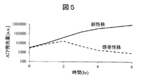
- FIG. 5 is a graph showing changes over time in the amount of ATP emitted from resistant strains and sensitive strains of Staphylococcus aureus with respect to cefoxitin (CFX) 4 ⁇ g / mL as an antibacterial agent.
- the culture was carried out at 37 ° C., and the amount of ATP luminescence was measured every hour.
- resistant strains the amount of ATP luminescence increased after 2 hours of culture compared to 0 hours immediately after sample treatment, so it can be determined that the strains are growing.
- the sensitive strain since it decreases after 2 hours as compared with the amount of ATP luminescence immediately after the sample treatment, it can be determined as blocking.
- Example 2 In the present embodiment, an example of a sample processing apparatus in which a centrifuge is sealed to improve the temperature control efficiency will be described.
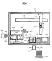
- FIG. 6 is a schematic diagram showing a configuration example of the sample processing apparatus of the present embodiment.
- the overlapping description is abbreviate
- the centrifuge 130 includes a fixed lid 600 and a movable lid 601 at the top.
- the temperature controller 160 is connected to the inside of the centrifuge 130 via a temperature control pipe 161.
- the temperature inside the centrifuge 130 is measured by a temperature sensor 652 provided inside the centrifuge 130.
- the reagent bottle rack 143 is provided with a temperature adjusting device 610 for the reagent bottle that adjusts the temperature of the reagent bottle 142.
- a position sensor 650 that detects whether or not a sample container exists at a work position in the centrifuge 130 is provided.
- an optical sensor or an ultrasonic sensor using reflected light is used for the position sensor 650.
- the position sensor 650 By confirming that the sample container 150 is installed at a position in the centrifuge 130 accessed by the pump 120 by the position sensor 650, if the user forgets to install the sample container 150, such as reagent dispensing. The operation prevents the inside of the centrifuge 130 from being contaminated.
- the fixed lid 600 has a detachable structure, and the fixed lid 600 can be removed when installing or removing the specimen container 150 from the centrifuge 130.
- the fixed lid 600 is fixed to the upper part of the centrifuge 130.
- FIG. 7 is a schematic view showing an example of a centrifuge of the sample processing apparatus, and is a view of the centrifuge 130 in a state where the fixed lid 600 is removed as viewed from above.
- a temperature control pipe 161 is connected inside the centrifuge 130, and the temperature inside the centrifuge 130 is adjusted by the temperature controller 160.
- the temperature control pipe 161 is provided with a filter 162, which can prevent airborne bacteria, impurities, and the like from entering the sample container 150.
- FIG. 8 and 9 are schematic views of the centrifuge 130 provided with the fixed lid 600 and the movable lid 601 as viewed from above.
- the movable lid 601 is slid by an automatic stage 603 and can be opened and closed.
- FIG. 8 shows a state where the movable lid 601 is closed
- FIG. 9 shows a state where the movable lid 601 is opened.
- the fixed lid 600 does not cover the entire upper surface of the centrifuge 130 but has a shape in which a part thereof is cut out so that the sample container 150 placed at the working position in the centrifuge can be accessed from above.
- the movable lid 601 has a shape that can close the notched opening of the fixed lid 600 and seal the upper part of the centrifuge 130 together with the fixed lid 600. Therefore, when the movable lid 601 is closed, the centrifuge is hermetically sealed as shown in FIG. 8, and when the movable lid 601 is opened, the inside of the centrifuge is opened from the notched opening of the fixed lid 600 as shown in FIG. The working position can be accessed.
- FIG. 10 and 11 are schematic views showing a cross section of a centrifuge having a fixed lid and a movable lid.
- FIG. 10 shows a state where the movable lid 601 is opened
- FIG. 11 shows a state where the movable lid 601 is closed.
- the movable lid 601 is opened only when processing using the pump 120 is performed on the sample container 150 in the centrifuge 130, and the movable lid 601 is closed when the processing is completed.
- sample processing such as centrifugation
- the movable lid 601 is closed and the centrifuge 130 is sealed as shown in FIG.
- FIG. 12 is a flowchart showing an example of a procedure when centrifugation and supernatant removal are performed in the sample processing apparatus of this example.
- step S41 If the movable lid 601 is opened after work such as sample exchange, the movable lid 601 is closed and the upper part of the centrifuge 130 is sealed (S41).
- the set temperature at the time of operation is compared with the current temperature (S42). If the set temperature is reached, the process proceeds to step S44. If the set temperature is different from the set temperature, the temperature controller 160 is used to wait until the set temperature is reached. (S43). In step S44, centrifugation is performed at a predetermined number of revolutions / time which is a preset centrifugation condition. After completion of the centrifugation, the pump 120 is moved to the access position on the pipette tip rack 141 by the X stage 110.
- the Z stage 111 is driven to lower the pump 120, and a predetermined pipette tip 140 is attached to the tip of the pump 120 (S45).
- the centrifuge 130 is rotated, and the sample container containing the sample to be subjected to the supernatant removal is moved to the working position among the sample containers 150 in the centrifuge 130 (S46).
- the X stage 110 is moved to the working position on the centrifuge 130, that is, the access position for the sample container in the centrifuge (S47).
- the Z stage 111 is driven to lower the pump 120, and the specimen container is passed through the notched opening of the fixed lid 600.
- the pipette tip 140 is immersed in the specimen in 150, and a set amount of supernatant is aspirated by the pump 120 (S48).
- the Z stage 111 is driven to move the pump 120 upward, the pipette tip 140 is taken out of the centrifuge, the movable lid 601 is closed, and the upper part of the centrifuge is sealed again (S49).
- the X stage 110 is driven to move the pump 120 onto the disposal box 145, and the pipette tip 140 is removed together with the supernatant (S50). It is determined whether or not the processing for all the samples has been completed (S51), and if there remains any unprocessed sample, the process returns to step S45 to process the next sample.
- the opening and closing of the movable lid 601 is limited when the pump 120 performs processing on the sample in the sample container 150, whereby the temperature fluctuation in the centrifuge 130 is reduced and the temperature is stabilized.
- the risk of contamination such as impurities can be reduced.
- the size of the movable lid 601 in other words, the size of the opening of the fixed lid 600, the outer diameter of the pipette tip 140 and the pump 120 so that the pipette tip 140 can be inserted into the sample container 150 as shown in FIG. 10.
- the outer diameter of the nozzle is preferably as small as possible.
- it is desirable that the opening has an area of about 1 to 4 times the area of the opening of the sample container 150.
- the opening / closing mechanism of the movable lid 601 is not limited to the slide type.
- 13 and 14 are schematic cross-sectional views illustrating another example of the opening / closing mechanism of the movable lid of the centrifuge.
- the movable lid may be opened and closed up and down as in the example shown in FIG. Moreover, as shown in FIG. 14, it is good also as a structure where two movable lids on either side open and close up and down.
- the movable lid 601 is driven by the drive unit 605 to open and close the opening of the fixed lid 600.
- Example 3 In this embodiment, an example of a sample processing apparatus capable of measuring the amount of pellets after centrifugation with a centrifuge and improving the efficiency of supernatant removal will be described.
- FIG. 15 is a schematic cross-sectional view showing a configuration example of the sample processing apparatus of the present embodiment.
- FIG. 16 is a partially enlarged view of FIG. About the part which attached
- the sample processing apparatus of this embodiment has a transparent window 1201 on the outer wall facing the working position of the centrifuge 130, and a light source 1202 that illuminates the sample container 150 that has reached the working position is provided in the centrifuge 130. .
- An interface detection sensor 1203 is provided outside the centrifuge 130 so as to face the transparent window 1201. As shown in FIG. 16, the interface detection sensor 1203 passes through the transparent window 1201 and the position of the gas-liquid interface 1205 of the sample in the sample container 150 arranged at the position in the centrifuge 130 accessed by the pump 120 and / or The position of the interface 1207 between the pellet and the supernatant after centrifugation is detected.
- the transparent window 1201 and the interface detection sensor 1203 are installed near the work position in the centrifuge 130.
- the position information of the gas-liquid interface 1205 and the pellet interface 1207 obtained by the interface detection sensor 1203 is converted into a distance from the bottom surface of the sample container 150 and recorded in the control PC 170, and the position information of the pipette tip 140 attached to the pump 120 is recorded. Used to control the tip position. For example, when removing the supernatant after centrifugation, it is necessary to aspirate only the supernatant without winding up the pellet. Therefore, it is desirable to suck up the tip of the pipette tip 140 as far as possible from the pellet.
- the control PC 170 monitors the height of the gas-liquid interface 1205 when removing the supernatant with the interface detection sensor 1203, and the drive control device 171 drives the Z stage 111 based on the information to suck the supernatant.
- the control PC 170 monitors the height of the gas-liquid interface 1205 when removing the supernatant with the interface detection sensor 1203, and the drive control device 171 drives the Z stage 111 based on the information to suck the supernatant.
- the control PC 170 monitors the height of the gas-liquid interface 1205 when removing the supernatant with the interface detection sensor 1203, and the drive control device 171 drives the Z stage 111 based on the information to suck the supernatant.
- the interface detection sensor 1203 images the specimen in the specimen container 150 using an imaging device such as a CCD or CMOS. After each step, the sample processing effect can be visually recognized by imaging the state of the sample.
- the interface detection sensor 1203 may perform interface detection using laser reflected light or transmitted light. Alternatively, a liquid level detection technique using ultrasonic waves or radio waves, or a capacitive liquid level detection technique may be used.
- the interface detection sensor 1203 may be installed inside the centrifuge 130. In that case, there is an advantage that the transparent window 1201 becomes unnecessary. When the interface detection sensor 1203 is installed inside, the volume inside the centrifuge 130 is reduced, so that the effect of improving the temperature control efficiency can be obtained.
- Example 4 In the present embodiment, an example of a sample processing apparatus that includes a luminescence measurement container and can perform a ATP erasing / extraction process by separating a part of a sample for each culture time will be described.
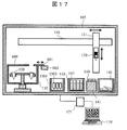
- FIG. 17 is a schematic diagram showing another configuration example of the sample processing apparatus of the present embodiment.
- symbol same as FIG.1 and FIG.6 the overlapping description is abbreviate
- the sample processing apparatus of the present embodiment includes a luminescence measurement container rack 1301 for storing a plurality of luminescence measurement containers 1303 in the housing 105.
- a luminescence measurement container rack 1301 for storing a plurality of luminescence measurement containers 1303 in the housing 105.
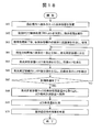
- FIG. 18 is a flowchart showing an example of a procedure for performing a drug sensitivity test using ATP using the sample processing apparatus of the present embodiment.
- a sample container 150 containing the sample is installed in the centrifuge 130 (S61). At this time, necessary reagents and pipette tips are also installed in the sample processing apparatus.
- a sample processing protocol is designated by the control PC 170, and sample processing is executed (S62). After completion of the sample processing, a predetermined antibacterial agent is dispensed into each sample container 150 with the pump 120. The antibacterial agent is stored in the reagent bottle 142 in the reagent bottle rack 143.
- the temperature in the centrifuge 130 is set to 37 ° C. and culture is performed (S63).
- a part of the sample in the sample container 150 is dispensed by the pump 120 into the luminescence measurement container 1303 in the luminescence measurement container rack 1301 (S64). .
- the ATP erasing solution in the reagent bottle 142 is dispensed into the luminescence measurement container 1303, and the floating ATP in the sample is erased (S65).
- the ATP extract is dispensed into the luminescence measurement container 1303 to extract ATP derived from viable bacteria (S66).
- step S67 it is determined whether all measurement preparations are completed.
- step S64 to S66 are repeated over the antibacterial species and concentration for which sensitivity is measured. It is repeated at every measurement time. Thereafter, the luminescence measurement container rack 1301 is taken out from the sample processing apparatus and installed in a known luminescence measurement apparatus (S68). The amount of ATP luminescence is measured by a known method in the luminescence measuring device (S69). Finally, bacterial growth or inhibition is determined from the change in the amount of ATP at each measurement time (S70).
- this invention is not limited to the above-mentioned Example, Various modifications are included.
- the above-described embodiments have been described in detail for easy understanding of the present invention, and are not necessarily limited to those having all the configurations described.
- a part of the configuration of one embodiment can be replaced with the configuration of another embodiment, and the configuration of another embodiment can be added to the configuration of one embodiment.
Abstract
La présente invention élimine le besoin de transport d'échantillon entre traitements et réduit le temps requis pour le traitement d'échantillon. La présente invention comprend : une centrifugeuse (130) destinée à la centrifugation d'un échantillon dans un récipient pour échantillon (150) ; une pompe (120) servant à aspirer et à évacuer des solutions ; un étage (110, 111) permettant de déplacer la pompe ; un support d'embouts de pipettes (141) permettant de recevoir des embouts de pipettes jetables (140) devant être fixés à l'extrémité avant de la pompe ; un support de flacons de réactifs (143) permettant de recevoir des flacons de réactifs (142) ; un boîtier (105) qui contient la centrifugeuse, la pompe, l'étage, le support d'embouts de pipettes et un support de flacons de réactifs, installé en son sein et apte à former un espace étanche ; un dispositif de commande de température (160) permettant de commander la température à l'intérieur du boîtier ; et un dispositif de commande d'entraînement (171) permettant d'entraîner la centrifugeuse, la pompe et l'étage. La pompe peut être sélectivement déplacée par l'étage jusqu'à une position permettant d'accéder à un embout de pipette jetable logé dans le support d'embouts de pipettes, une position permettant d'accéder à un flacon de réactif logé dans le support de flacons de réactifs, ou jusqu'à une position permettant d'accéder au récipient pour échantillon dans la centrifugeuse.
Applications Claiming Priority (2)
| Application Number | Priority Date | Filing Date | Title |
|---|---|---|---|
| JP2017-066889 | 2017-03-30 | ||
| JP2017066889A JP6660910B2 (ja) | 2017-03-30 | 2017-03-30 | 自動検体処理装置 |
Publications (1)
| Publication Number | Publication Date |
|---|---|
| WO2018179530A1 true WO2018179530A1 (fr) | 2018-10-04 |
Family
ID=63675013
Family Applications (1)
| Application Number | Title | Priority Date | Filing Date |
|---|---|---|---|
| PCT/JP2017/036788 WO2018179530A1 (fr) | 2017-03-30 | 2017-10-11 | Dispositif automatique de traitement d'échantillon |
Country Status (2)
| Country | Link |
|---|---|
| JP (1) | JP6660910B2 (fr) |
| WO (1) | WO2018179530A1 (fr) |
Cited By (1)
| Publication number | Priority date | Publication date | Assignee | Title |
|---|---|---|---|---|
| CN111965291A (zh) * | 2020-05-12 | 2020-11-20 | 长治市农产品质量安全检验监测中心 | 一种样品处理方法及自动处理装置 |
Families Citing this family (5)
| Publication number | Priority date | Publication date | Assignee | Title |
|---|---|---|---|---|
| CN113994215A (zh) * | 2019-06-24 | 2022-01-28 | 积水医疗株式会社 | 自动分析装置 |
| CN113906286A (zh) * | 2019-07-02 | 2022-01-07 | 株式会社堀场先进技术 | 生物体样品分析装置及生物体样品分析方法 |
| KR102168826B1 (ko) * | 2019-11-29 | 2020-10-22 | 주식회사 한국바이오 셀프 | 검체 분리 장치 및 방법 |
| KR102332602B1 (ko) * | 2021-03-08 | 2021-12-02 | 주식회사 싸이토딕스 | 유체 처리 시스템 |
| KR20230022564A (ko) * | 2021-08-09 | 2023-02-16 | 주식회사 싸이토딕스 | 유체 처리 시스템 및 이를 이용한 원심 분리 방법 |
Citations (7)
| Publication number | Priority date | Publication date | Assignee | Title |
|---|---|---|---|---|
| JPS6080734A (ja) * | 1983-10-07 | 1985-05-08 | Hitachi Ltd | 液体試料自動分析装置 |
| JPH10260118A (ja) * | 1997-03-19 | 1998-09-29 | Dainippon Seiki:Kk | 液体試料中の成分物質の自動抽出装置および液体試料中の成分物質の自動濃度測定装置 |
| US20020037588A1 (en) * | 2000-04-14 | 2002-03-28 | Rob Neeper | Container and method for high volume treatment of samples on solid supports |
| JP2009058409A (ja) * | 2007-08-31 | 2009-03-19 | Nsk Ltd | 遠心力付与装置及び検体液分析装置 |
| JP2014235076A (ja) * | 2013-06-03 | 2014-12-15 | 株式会社日立ハイテクノロジーズ | 血球破壊試薬及びそれを用いる血球破壊方法 |
| WO2017006969A1 (fr) * | 2015-07-07 | 2017-01-12 | コニカミノルタ株式会社 | Dispositif de détection et procédé de détection |
| JP2017044648A (ja) * | 2015-08-28 | 2017-03-02 | 富士フイルム株式会社 | 検査装置及びその作動方法 |
-
2017
- 2017-03-30 JP JP2017066889A patent/JP6660910B2/ja active Active
- 2017-10-11 WO PCT/JP2017/036788 patent/WO2018179530A1/fr active Application Filing
Patent Citations (7)
| Publication number | Priority date | Publication date | Assignee | Title |
|---|---|---|---|---|
| JPS6080734A (ja) * | 1983-10-07 | 1985-05-08 | Hitachi Ltd | 液体試料自動分析装置 |
| JPH10260118A (ja) * | 1997-03-19 | 1998-09-29 | Dainippon Seiki:Kk | 液体試料中の成分物質の自動抽出装置および液体試料中の成分物質の自動濃度測定装置 |
| US20020037588A1 (en) * | 2000-04-14 | 2002-03-28 | Rob Neeper | Container and method for high volume treatment of samples on solid supports |
| JP2009058409A (ja) * | 2007-08-31 | 2009-03-19 | Nsk Ltd | 遠心力付与装置及び検体液分析装置 |
| JP2014235076A (ja) * | 2013-06-03 | 2014-12-15 | 株式会社日立ハイテクノロジーズ | 血球破壊試薬及びそれを用いる血球破壊方法 |
| WO2017006969A1 (fr) * | 2015-07-07 | 2017-01-12 | コニカミノルタ株式会社 | Dispositif de détection et procédé de détection |
| JP2017044648A (ja) * | 2015-08-28 | 2017-03-02 | 富士フイルム株式会社 | 検査装置及びその作動方法 |
Cited By (2)
| Publication number | Priority date | Publication date | Assignee | Title |
|---|---|---|---|---|
| CN111965291A (zh) * | 2020-05-12 | 2020-11-20 | 长治市农产品质量安全检验监测中心 | 一种样品处理方法及自动处理装置 |
| CN111965291B (zh) * | 2020-05-12 | 2022-06-07 | 长治市农产品质量安全检验监测中心 | 一种农药残留样品处理方法 |
Also Published As
| Publication number | Publication date |
|---|---|
| JP2018169291A (ja) | 2018-11-01 |
| JP6660910B2 (ja) | 2020-03-11 |
Similar Documents
| Publication | Publication Date | Title |
|---|---|---|
| WO2018179530A1 (fr) | Dispositif automatique de traitement d'échantillon | |
| CN208367018U (zh) | 实验室仪器、对分析物进行试验的自动化系统和移动微生物试验板的机电组件 | |
| AU2021277713B2 (en) | Performing antimicrobial susceptibility testing and related systems and methods | |
| CN102460177B (zh) | 用于对培养试样容器进行自动地通风和取样的系统和方法 | |
| US9856503B2 (en) | Combined detection instrument for culture specimen containers and instrument for identification and/or characterization of a microbial agent in a sample | |
| JP5728196B2 (ja) | 試料調製装置および試料調製方法 | |
| US20060002820A1 (en) | Multi-level diagnostic apparatus with a lift system | |
| KR102168826B1 (ko) | 검체 분리 장치 및 방법 | |
| US10481098B2 (en) | Luminometer apparatus | |
| JPWO2018181481A1 (ja) | 測光分注ノズルユニット、測光分注装置、および測光分注処理方法 | |
| JP2019507350A (ja) | 体外診断用自動分析システム | |
| EP1582875A1 (fr) | Analyseur avec ascenseur | |
| WO2016103433A1 (fr) | Procédé, dispositif et système de test de sensibilité aux médicaments | |
| JP2005341813A (ja) | 培養処理装置および自動培養装置 | |
| JP2023508898A (ja) | サンプル調製器具 | |
| JP2019041774A (ja) | 薬剤感受性試験システム | |
| JP2005341877A (ja) | 培養処理装置、自動培養装置、接触検出方法、および液滴検出方法 | |
| JP2005333824A (ja) | 検体導入装置および培養処理装置 | |
| JP2000346834A (ja) | アルミニウム測定方法および測定装置 |
Legal Events
| Date | Code | Title | Description |
|---|---|---|---|
| 121 | Ep: the epo has been informed by wipo that ep was designated in this application |
Ref document number: 17903066 Country of ref document: EP Kind code of ref document: A1 |
|
| NENP | Non-entry into the national phase |
Ref country code: DE |
|
| 122 | Ep: pct application non-entry in european phase |
Ref document number: 17903066 Country of ref document: EP Kind code of ref document: A1 |