WO2018173902A1 - Interchangeable lens and method for controlling same, imaging device, and camera system - Google Patents
Interchangeable lens and method for controlling same, imaging device, and camera system Download PDFInfo
- Publication number
- WO2018173902A1 WO2018173902A1 PCT/JP2018/010123 JP2018010123W WO2018173902A1 WO 2018173902 A1 WO2018173902 A1 WO 2018173902A1 JP 2018010123 W JP2018010123 W JP 2018010123W WO 2018173902 A1 WO2018173902 A1 WO 2018173902A1
- Authority
- WO
- WIPO (PCT)
- Prior art keywords
- diaphragm
- control unit
- driving
- aperture
- lens
- Prior art date
Links
Images


Classifications
-
- H—ELECTRICITY
- H04—ELECTRIC COMMUNICATION TECHNIQUE
- H04N—PICTORIAL COMMUNICATION, e.g. TELEVISION
- H04N23/00—Cameras or camera modules comprising electronic image sensors; Control thereof
- H04N23/70—Circuitry for compensating brightness variation in the scene
- H04N23/75—Circuitry for compensating brightness variation in the scene by influencing optical camera components
-
- G—PHYSICS
- G03—PHOTOGRAPHY; CINEMATOGRAPHY; ANALOGOUS TECHNIQUES USING WAVES OTHER THAN OPTICAL WAVES; ELECTROGRAPHY; HOLOGRAPHY
- G03B—APPARATUS OR ARRANGEMENTS FOR TAKING PHOTOGRAPHS OR FOR PROJECTING OR VIEWING THEM; APPARATUS OR ARRANGEMENTS EMPLOYING ANALOGOUS TECHNIQUES USING WAVES OTHER THAN OPTICAL WAVES; ACCESSORIES THEREFOR
- G03B9/00—Exposure-making shutters; Diaphragms
- G03B9/02—Diaphragms
-
- G—PHYSICS
- G03—PHOTOGRAPHY; CINEMATOGRAPHY; ANALOGOUS TECHNIQUES USING WAVES OTHER THAN OPTICAL WAVES; ELECTROGRAPHY; HOLOGRAPHY
- G03B—APPARATUS OR ARRANGEMENTS FOR TAKING PHOTOGRAPHS OR FOR PROJECTING OR VIEWING THEM; APPARATUS OR ARRANGEMENTS EMPLOYING ANALOGOUS TECHNIQUES USING WAVES OTHER THAN OPTICAL WAVES; ACCESSORIES THEREFOR
- G03B13/00—Viewfinders; Focusing aids for cameras; Means for focusing for cameras; Autofocus systems for cameras
- G03B13/32—Means for focusing
- G03B13/34—Power focusing
- G03B13/36—Autofocus systems
-
- G—PHYSICS
- G03—PHOTOGRAPHY; CINEMATOGRAPHY; ANALOGOUS TECHNIQUES USING WAVES OTHER THAN OPTICAL WAVES; ELECTROGRAPHY; HOLOGRAPHY
- G03B—APPARATUS OR ARRANGEMENTS FOR TAKING PHOTOGRAPHS OR FOR PROJECTING OR VIEWING THEM; APPARATUS OR ARRANGEMENTS EMPLOYING ANALOGOUS TECHNIQUES USING WAVES OTHER THAN OPTICAL WAVES; ACCESSORIES THEREFOR
- G03B17/00—Details of cameras or camera bodies; Accessories therefor
- G03B17/02—Bodies
- G03B17/12—Bodies with means for supporting objectives, supplementary lenses, filters, masks, or turrets
- G03B17/14—Bodies with means for supporting objectives, supplementary lenses, filters, masks, or turrets interchangeably
-
- G—PHYSICS
- G03—PHOTOGRAPHY; CINEMATOGRAPHY; ANALOGOUS TECHNIQUES USING WAVES OTHER THAN OPTICAL WAVES; ELECTROGRAPHY; HOLOGRAPHY
- G03B—APPARATUS OR ARRANGEMENTS FOR TAKING PHOTOGRAPHS OR FOR PROJECTING OR VIEWING THEM; APPARATUS OR ARRANGEMENTS EMPLOYING ANALOGOUS TECHNIQUES USING WAVES OTHER THAN OPTICAL WAVES; ACCESSORIES THEREFOR
- G03B7/00—Control of exposure by setting shutters, diaphragms or filters, separately or conjointly
- G03B7/003—Control of exposure by setting shutters, diaphragms or filters, separately or conjointly setting of both shutter and diaphragm
-
- H—ELECTRICITY
- H04—ELECTRIC COMMUNICATION TECHNIQUE
- H04N—PICTORIAL COMMUNICATION, e.g. TELEVISION
- H04N23/00—Cameras or camera modules comprising electronic image sensors; Control thereof
- H04N23/60—Control of cameras or camera modules
- H04N23/67—Focus control based on electronic image sensor signals
- H04N23/672—Focus control based on electronic image sensor signals based on the phase difference signals
-
- H—ELECTRICITY
- H04—ELECTRIC COMMUNICATION TECHNIQUE
- H04N—PICTORIAL COMMUNICATION, e.g. TELEVISION
- H04N23/00—Cameras or camera modules comprising electronic image sensors; Control thereof
- H04N23/60—Control of cameras or camera modules
- H04N23/68—Control of cameras or camera modules for stable pick-up of the scene, e.g. compensating for camera body vibrations
- H04N23/681—Motion detection
- H04N23/6812—Motion detection based on additional sensors, e.g. acceleration sensors
-
- H—ELECTRICITY
- H04—ELECTRIC COMMUNICATION TECHNIQUE
- H04N—PICTORIAL COMMUNICATION, e.g. TELEVISION
- H04N23/00—Cameras or camera modules comprising electronic image sensors; Control thereof
- H04N23/60—Control of cameras or camera modules
- H04N23/68—Control of cameras or camera modules for stable pick-up of the scene, e.g. compensating for camera body vibrations
- H04N23/682—Vibration or motion blur correction
- H04N23/685—Vibration or motion blur correction performed by mechanical compensation
- H04N23/687—Vibration or motion blur correction performed by mechanical compensation by shifting the lens or sensor position
-
- H—ELECTRICITY
- H04—ELECTRIC COMMUNICATION TECHNIQUE
- H04N—PICTORIAL COMMUNICATION, e.g. TELEVISION
- H04N23/00—Cameras or camera modules comprising electronic image sensors; Control thereof
- H04N23/50—Constructional details
- H04N23/55—Optical parts specially adapted for electronic image sensors; Mounting thereof
Definitions
- the present technology relates to an interchangeable lens and a control method thereof, an imaging apparatus, and a camera system, and in particular, an interchangeable lens and a control method thereof that can start imaging in consideration of mechanical shaking after driving a diaphragm.
- the present invention relates to an imaging device and a camera system.
- the diaphragm of the imaging device is composed of, for example, seven blades and adjusts the amount of light passing through the optical system by increasing or decreasing the aperture diameter.
- the diaphragm blades are generally driven by a motor via a gear or a shaft.
- imaging devices there is known an imaging device that starts imaging after the diaphragm adjustment is completed.
- the aperture size of the aperture can be changed to the target size by overshooting or undershooting the target size even after the motor is driven due to factors such as backlash between gears and twisting of the shaft. Converge. Since it is not possible to know the time until overshoot or undershoot stops, for example, imaging may be started in a state where the mechanical operation of the aperture is not completed.
- the present technology has been made in view of such a situation, and enables imaging to be started in consideration of mechanical shaking after driving the diaphragm.
- the interchangeable lens according to the first aspect of the present technology includes an aperture, an aperture drive unit that drives the aperture, and aperture drive information that includes stationary time information of the aperture when the aperture drive unit drives the aperture
- a lens control unit that transmits the image to the imaging device.
- a method for controlling an interchangeable lens including a diaphragm, a diaphragm drive unit that drives the diaphragm, and a lens control unit.
- Aperture driving information including stationary stop time information when driving the aperture is transmitted to the imaging device.
- diaphragm drive information including stationary time information of the diaphragm when the diaphragm drive unit drives the diaphragm is transmitted to the imaging device.
- the imaging device includes a body control unit that determines exposure start timing based on aperture driving information including aperture stabilization time information acquired from an interchangeable lens.
- the exposure start timing is determined based on aperture drive information including aperture stabilization time information acquired from the interchangeable lens.
- a camera system includes an interchangeable lens and an imaging device on which the interchangeable lens is mounted.
- the interchangeable lens includes a diaphragm, a diaphragm drive unit that drives the diaphragm, and the diaphragm drive.
- a lens control unit that transmits aperture drive information including stationary stop time information to the imaging device when the unit drives the aperture, and the imaging device performs exposure based on the aperture drive information.
- a body control unit for determining the start timing is provided.
- diaphragm drive information including the stationary time information of the diaphragm when the diaphragm drive unit drives the diaphragm is transmitted to the imaging device. Based on the aperture drive information, the exposure start timing is determined.
- FIG. 1 is a block diagram illustrating a configuration example of an embodiment of a camera system to which the present technology is applied.
- 1 is an interchangeable lens digital camera, and includes a detachable interchangeable lens 10 and an imaging device 60 on the body side.
- the interchangeable lens 10 includes a mount portion 21 that is detachably attached to the mount portion 71 of the imaging device 60.
- the mount unit 21 has a plurality of terminals (not shown) that are electrically connected to the mount unit 71 of the imaging device 60.
- the interchangeable lens 10 includes a lens control unit 22, a zoom lens 23, a camera shake correction lens 24, an aperture 25, an objective side focus lens 26, an element side focus lens 27, an operation unit 28, a memory unit 29, a recording unit 30, and power control.
- the unit 31 and the temperature sensor 32 are provided.
- the interchangeable lens 10 has two types of focus lenses, an objective side focus lens 26 and an element side focus lens 27, for autofocus control.
- the objective side focus lens 26 is an objective lens among the two types of focus lenses.
- the focus lens on the side close to a lens (not shown), and the element-side focus lens 27 is a focus lens on the side close to the image pickup element 76 of the image pickup device 60.
- Each focus lens of the objective side focus lens 26 and the element side focus lens 27 includes one or a plurality of optical elements.
- the lens control unit 22 includes, for example, an arithmetic processing unit such as a CPU (Central Processing Unit) or an MPU (Micro Processing Unit) and peripheral circuits, and reads and executes a predetermined control program recorded in the recording unit 30. By doing so, the entire interchangeable lens 10 is controlled.
- an arithmetic processing unit such as a CPU (Central Processing Unit) or an MPU (Micro Processing Unit) and peripheral circuits, and reads and executes a predetermined control program recorded in the recording unit 30. By doing so, the entire interchangeable lens 10 is controlled.
- the lens control unit 22 determines the position of the zoom lens 23 according to an instruction from the imaging device 60 supplied via a predetermined communication terminal of the mount unit 21 or a user operation received by the operation unit 28. Control. More specifically, the lens control unit 22 acquires the current position of the zoom lens 23 from the zoom position detection unit 41, and the driving direction and driving amount for moving the zoom lens 23 to a predetermined position based on the acquisition result. And the determined drive direction and drive amount are output to the zoom drive unit 42 together with the movement command.
- the zoom position detection unit 41 is configured by, for example, a magnetic sensor (MR sensor), and detects the position of the zoom lens 23 and supplies the detected position to the lens control unit 22.
- the zoom driving unit 42 moves the zoom lens 23 in the optical axis direction so as to achieve the instructed driving direction and driving amount based on the movement command supplied from the lens control unit 22.
- the lens control unit 22 controls the camera shake correction lens 24 so as to correct the camera shake. Specifically, the lens control unit 22 determines the drive direction and the drive amount of the camera shake correction lens 24 in the direction to cancel the camera shake amount based on the camera shake amount detected by the camera shake detection unit 43, and determines the determined drive direction. The driving amount is output to the camera shake driving unit 44 together with the movement command.
- the camera shake detection unit 43 includes a gyro sensor, a triaxial acceleration sensor, and the like.
- the gyro sensor is used when detecting a shift (blur) in the direction corresponding to Pitch or Yaw as the correction direction of the camera shake correction lens 24.
- the triaxial acceleration sensor is used when the optical axis direction is the Z axis.
- the camera shake detection unit 43 may be either a gyro sensor or a triaxial acceleration sensor, or may include both. Based on the movement command supplied from the lens control unit 22, the camera shake driving unit 44 moves the camera shake correction lens 24 so that the instructed driving direction and driving amount are obtained.
- the lens control unit 22 controls the aperture diameter of the diaphragm 25 according to an instruction from the imaging device 60 supplied via a predetermined communication terminal of the mount unit 21. Specifically, the lens control unit 22 acquires the aperture diameter of the diaphragm 25 detected by the diaphragm detection unit 45 and adjusts the aperture driving unit 46 so that the F value (aperture value) instructed from the imaging device 60 is obtained. The diaphragm 25 is driven. The aperture driving unit 46 drives the aperture 25 so that the aperture diameter designated by the lens control unit 22 is obtained.
- the lens control unit 22 controls two types of focus lenses, that is, an objective side focus lens 26 and an element side focus lens 27. Specifically, the lens control unit 22 acquires the current position of the objective side focus lens 26 from the objective side lens position detection unit 47, and moves the objective side focus lens 26 to a predetermined position based on the acquisition result. The drive direction and drive amount are determined, and the determined drive direction and drive amount are output to the objective lens drive unit 48 together with the movement command. The objective side lens driving unit 48 moves the objective side focus lens 26 in the optical axis direction so that the instructed driving direction and driving amount are obtained.
- the lens control unit 22 acquires the current position of the element-side focus lens 27 from the element-side lens position detection unit 49, and moves the element-side focus lens 27 to a predetermined position based on the acquisition result. Then, the driving amount is determined, and the determined driving direction and driving amount are output to the element side lens driving unit 50 together with the movement command.
- the element side lens driving unit 50 moves the element side focus lens 27 in the optical axis direction so that the instructed driving direction and driving amount are obtained.
- the objective-side lens position detection unit 47 and the element-side lens position detection unit 49 can be configured by, for example, a magnetic sensor, a photodiode array, a potentiometer, a reflective encoder, and the like.
- an ultrasonic motor for example, an ultrasonic motor, a DC motor, a linear actuator, a stepping motor, or a piezoelectric element (piezoelectric element) can be used for the objective side lens driving unit 48 and the element side lens driving unit 50.
- a DC motor or an ultrasonic motor is suitable.
- the interchangeable lens 10 has two types of focus lenses, that is, the objective-side focus lens 26 and the element-side focus lens 27, generally, the objective-side focus lens 26 is a heavier lens.
- the interchangeable lens 10 does not necessarily have two types of focus lenses, and either the objective side focus lens 26 or the element side focus lens 27 may be omitted. In this case, the lens position detection unit and the lens driving unit that are necessary for the control of the omitted focus lens are also omitted.
- the operation unit 28 corresponds to a zoom ring for manually setting the zoom magnification, a focus ring for manually setting the focus lens, and the like.
- the operation unit 28 receives a user's manual operation and sends an operation signal corresponding to the received operation to the lens control unit 22. Supply.
- the memory unit 29 is a volatile storage medium such as RAM (Random Access Memory), and is used as a storage area for various data during operation.
- RAM Random Access Memory
- the recording unit 30 is a non-volatile storage medium, and the recording unit 30 stores various data such as a predetermined control program executed by the lens control unit 22 and adjustment parameters.
- the power supply control unit 31 detects the amount of power of the power supplied from the imaging device 60, and based on the detected amount of power, power is supplied to each unit (the lens control unit 22 and various drive units) in the interchangeable lens 10. Supply power by optimally allocating the amount.
- the temperature sensor 32 detects the temperature around or inside the interchangeable lens 10 and supplies it to the lens control unit 22. The detection result of the temperature sensor 32 is used to determine a parameter when considering a temperature change.
- the imaging device 60 on the body side includes a mount portion 71 to which the interchangeable lens 10 is detachably attached.
- the mount portion 71 has a plurality of terminals (not shown) that are electrically connected to the mount portion 21 of the interchangeable lens 10.
- the connected terminals include, for example, a terminal for supplying power (power supply terminal), a terminal for transmitting commands and data (communication terminal), a terminal for transmitting a synchronization signal (synchronization signal terminal), and the like. is there.
- the imaging device 60 further includes a body control unit 72, a mechanical shutter 73, a shutter detection unit 74, a shutter drive unit 75, an imaging element 76, an image signal processing unit 77, a recording unit 78, a display unit 79, a power control unit 80, and a power supply unit. 81 and an operation unit 82.
- the body control unit 72 includes, for example, an arithmetic processing device such as a CPU (Central Processing Unit) or an MPU (Micro Processing Unit), a nonvolatile memory, a peripheral circuit, and the like, and is stored in an internal nonvolatile memory.
- an arithmetic processing device such as a CPU (Central Processing Unit) or an MPU (Micro Processing Unit), a nonvolatile memory, a peripheral circuit, and the like, and is stored in an internal nonvolatile memory.
- the entire camera system 1 is controlled by reading and executing a predetermined control program.
- the body control unit 72 causes the image sensor 76 to perform imaging based on an operation signal representing a user's predetermined operation supplied from the operation unit 82, or sends a predetermined command to the interchangeable lens via the mount unit 71. 10 to drive the focus lens (objective side focus lens 26, element side focus lens 27), zoom lens 23, and the like.
- lens position information of the focus lens, zoom position information of the zoom lens 23, and the like are supplied from the interchangeable lens 10 to the body control unit 72 via the mount unit 71, and the body control unit 72 performs the optimum based on the information.
- the image sensor 76 is caused to capture an image to be recorded in the recording unit 78 and an image for transmission to an external device at a proper timing.
- the image (data) obtained by the image sensor 76 is recorded (stored) in the recording unit 78 or displayed on the display unit 79 according to the control of the body control unit 72.
- the mechanical shutter 73 is disposed in front of the image sensor 76 and opens and closes according to the control of the shutter drive unit 75.
- the shutter detection unit 74 detects the open / close state of the mechanical shutter 73 and supplies it to the body control unit 72.
- the shutter drive unit 75 drives the mechanical shutter 73 to an open state or a closed state based on the control of the body control unit 72.
- the image sensor 76 is composed of, for example, a CCD (Charge Coupled Device) or a CMOS (Complementary Metal Oxide Semiconductor) sensor, captures a subject, generates image data, and outputs the image data.
- CCD Charge Coupled Device
- CMOS Complementary Metal Oxide Semiconductor
- the imaging element 76 includes a pixel array unit in which pixels (imaging pixels) that generate an image generation signal are arranged in a matrix.
- some of the pixels in the pixel array section include phase difference pixels that generate a focus detection signal.
- the phase difference pixel a part of the light receiving region is shielded by the light shielding film, and the light shielding region shielded by the light shielding film is focused from the pixel signal output from the two phase difference pixels that are symmetric with respect to the optical axis. Can be detected.
- the image pickup element 76 is configured by a CCD sensor or a CMOS sensor
- an electronic shutter can be used, and thus the mechanical shutter 73 can be omitted.
- the mechanical shutter 73 is omitted, the shutter detection unit 74 and the shutter driving unit 75 used for the control are also omitted.
- the image signal processing unit 77 performs predetermined image signal processing on the image supplied from the image sensor 76. For example, the image signal processing unit 77 converts a RAW image supplied from the image sensor 76 into image data in a predetermined file format and causes the recording unit 78 to record the image data. In addition, the image signal processing unit 77 performs demosaic processing on the RAW image, further converts the image data into a predetermined file format by lossless compression or lossy compression, and causes the recording unit 78 to record the image data. For example, the image signal processing unit 77 converts the image data supplied from the imaging element 76 into an image signal of a predetermined display format, and supplies the image signal to the display unit 79 to display the captured image.
- the recording unit 78 is composed of, for example, a nonvolatile memory, and records (stores) data of an image captured by the image sensor 76.
- a recording medium as the recording unit 78 may be detachable.
- the display unit 79 is configured by a panel type display device such as a liquid crystal panel or an organic EL (Electro Luminescence) panel, and displays an image (moving image or still image) supplied from the image signal processing unit 77.
- the display unit 79 is mounted on the rear surface opposite to the front surface on which the mount unit 71 is disposed, and can display a live view image, a preview image, and the like.
- the power control unit 80 supplies the power supplied from the power supply unit 81 to each unit of the imaging device 60.
- the power control unit 80 calculates the amount of power that can be supplied to the interchangeable lens 10 in consideration of the operating state of the imaging device 60, and supplies power to the interchangeable lens 10 via the mount unit 71.
- the power supply unit 81 includes, for example, a secondary battery such as a NiCd battery, a NiMH battery, or a Li battery, an AC adapter, or the like.
- the operation unit 82 includes hardware keys such as a release button, a mode dial, and a zoom button, and software keys using a touch panel stacked on the display unit 79.
- the operation unit 82 receives a predetermined operation performed by the user and sends the operation signal to the body control unit. 72.
- the user can set, for example, a shooting mode and camera parameters.
- the interchangeable lens 10 and the imaging device 60 constituting the camera system 1 have the above configuration.
- the imaging device 60 on the camera body side will be referred to as a body 60.
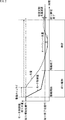
- FIG. 2 is a diagram for explaining the operation of the diaphragm 25 when the aperture diameter of the diaphragm 25 is changed.
- the horizontal axis represents time
- the vertical axis represents the control value of a motor (for example, a stepping motor) that changes the aperture diameter of the diaphragm 25 or the amount of light that passes through the diaphragm 25.
- a motor for example, a stepping motor
- the lens control unit 22 drives the diaphragm so as to obtain a light quantity (target light quantity value) corresponding to the designated F value.
- the diaphragm drive unit 46 drives the diaphragm 25 so that the amount of light is instructed from the lens control unit 22.
- the diaphragm drive unit 46 drives the motor to change the aperture diameter of the diaphragm 25 from the current start position P1 of the diaphragm 25 to the end position P2 of the diaphragm 25 corresponding to the designated F value. .
- the control value of the motor is changed at a predetermined speed gradient from the start position P1 to the end position P2.
- the aperture 25 is composed of, for example, seven blades, Since it is driven by a motor via a shaft or the like, the opening diameter of the diaphragm 25 and the amount of light passing through the opening region change with a predetermined delay (drive time lag) due to mechanical backlash or the like. Further, even after the motor control value reaches the end position P2 and the driving of the motor is finished, the opening diameter of the diaphragm 25 changes due to elastic strain or the like. Therefore, the amount of light passing through the opening area of the diaphragm 25 is overshoot or undershoot as shown by the broken line in FIG. 2, and the target amount of light corresponding to the end position P2 after a predetermined time has elapsed since the end of driving of the motor. Converges to a value.
- the aperture diameter of the aperture 25 is changed, the amount of light passing through the aperture area of the aperture 25 is terminated after the aperture driving operation for changing the motor control value to a value corresponding to the end position P2.
- a predetermined time is required until convergence is made within an error range in which it can be determined that the target light amount value corresponding to the position P2 has been reached.
- the operation during the period from the end of driving of the diaphragm 25 to the convergence to the target light amount value is referred to as a static operation, and the state during this period is referred to as a static state.
- the static operation is caused by, for example, a mechanical structure such as backlash between gears or twisting of the shaft. The causes of overshoot and undershoot in various mechanical structures of the diaphragm 25 will be described later with reference to FIGS.
- the time required for the stabilization operation varies depending on the type of the interchangeable lens 10 and the like, until now, for example, a uniform margin was secured on the body 60 side. However, if the time until the settling time is longer than the time secured on the body 60 side, imaging is performed in a state where the light amount of the diaphragm 25 is unstable (inaccurate). Alternatively, if the time until stabilization is shorter than the time secured on the body 60 side, an unnecessary time lag until the start of imaging occurs.
- an aperture 25 including a settling time indicating a time in a settling state is included.
- the drive end time is returned.
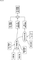
- Image processing time chart> With reference to the time chart of FIG. 3, the exposure of the recording image is started after the release button is fully pressed, which is an operation for starting the recording of the recording image that is to be recorded on the recording unit 78. The process up to this will be described.
- FIG. 3 the operation described in FIG. 3 is an AF mode suitable for a case where the subject is moving.
- the continuous AF mode in which the auto focus is activated and the focus is continuously maintained even while the release button is pressed halfway. Is the action.
- the horizontal axis direction in FIG. 3 represents time, and one period divided by a broken line corresponds to one period (for example, 1/60 sec) defined by a synchronization signal or a signal obtained by multiplying or dividing the synchronization signal.
- the body control unit 72 on the body 60 side maintains the focus position at the focus position at the timing when the full-press operation is performed in step S1 (focus). Lock).
- the diaphragm 25 is controlled to be smaller than a predetermined F value (for example, “11”). In this example, it is assumed that the F value is set to “8” in the focus lock state.
- the body control unit 72 sends a command to change the F value of the diaphragm 25 to a target F value (hereinafter referred to as a target F value) determined by user settings or the like, for example. 22 to send.
- a target F value a target F value
- step S3 When the lens control unit 22 on the interchangeable lens 10 side receives the command of the target F value transmitted from the body control unit 72, in step S3, from the current F value (hereinafter referred to as the current F value) to the target F value.
- the drive end time of the diaphragm 25 (hereinafter referred to as the “throttle drive end time”) including the stabilization time for changing the F value is calculated and transmitted to the body control unit 72.
- the lens control unit 22 calculates the time until time T1 in FIG.
- the stop driving end time transmitted from the lens control unit 22 to the body control unit 72 may be a time (required time) until the driving of the stop 25 ends, or may be a time at which the driving of the stop 25 ends. Any information indicating the drive end timing of 25 may be used. Further, the information indicating the drive end timing of the diaphragm 25 may be information corresponding to one point of time when the drive of the diaphragm 25 ends, or a predetermined width (period) including at least the time when the drive of the diaphragm 25 ends. It may be information.
- step S4 the lens control unit 22 supplies a drive command to the aperture drive unit 46 to start driving the aperture 25 to the target F value.
- steps S3 and S4 may be started first or may be executed simultaneously. That is, the timing at which the driving of the diaphragm 25 is started and the timing at which the lens control unit 22 transmits the diaphragm driving end time to the body control unit 72 are not limited.
- the body control unit 72 calculates an exposure start timing which is a timing at which the image sensor 76 starts exposure of the recording image in step S5.
- the exposure start timing in step S5 is calculated as follows, for example. First, the body control unit 72 predicts (calculates) the focus position when the aperture driving end time has elapsed from the movement of the subject detected when the subject is focused when the release button is half-pressed. . Next, the body control unit 72 predicts (calculates) a focus driving time when the focus control unit is moved to the predicted focus position from the difference between the predicted focus position and the current focus position. Then, the body control unit 72 calculates an exposure start timing at which exposure of the recording image can be started from the calculated focus drive time and the aperture drive end time transmitted from the lens control unit 22. The exposure start timing corresponds to the longer of the focus drive time or the aperture drive end time.
- step S6 the body control unit 72 calculates the focus lens (the objective-side focus lens 26 or the element-side focus lens 27 of the objective-side focus lens 27) at the focus target position that is the focus position when the diaphragm drive end time has elapsed, which is calculated in the process of step S5. Send a move command to move at least one).
- the body control unit 72 controls the focus lens (focusing control) and determines the exposure start timing.
- step S7 the lens control unit 22 performs focus drive processing for driving the focus lens to the focus target position in accordance with the focus lens movement command transmitted from the body control unit 72.
- step S8 the lens control unit 22 transmits a drive end of the focus lens to the body control unit 72.
- the body control unit 72 starts exposure (capture) for capturing an image for recording on the image sensor 76 in step S9, which is time T1 when the aperture driving end time has elapsed after receiving the driving end of the focus lens.
- the time T1 is a time at which the driving of the diaphragm 25 is completed including the settling time, it is possible to start imaging in consideration of mechanical shaking after driving the diaphragm. In other words, it is possible to start capturing a recording image at a timing that is not affected by the overshoot or undershoot of the diaphragm 25.
- the drive plan of the diaphragm 25 is calculated based on the current F value, target F value, diaphragm drive mode, individual adjustment data, and the like.
- the drive plan of the diaphragm 25 is information indicating the change (gradient) of the motor control value with the passage of time, which is indicated by the solid line during the diaphragm drive operation in the graph of FIG. It shows how to change the motor control value up to the target F value.
- the time taken for the subsequent static operation also varies.
- the lens controller 22 indicates that the first 3/4 of the moving distance from the start position P1 to the end position P2 is the first as indicated by the solid line during the aperture driving operation.
- the driving plan is calculated such that the driving is performed at the driving speed, and the last quarter is moved to the end position P2 at the second driving speed that is slower than the first driving speed. Note that the drive plan need not be linear control.
- the aperture drive mode has, for example, a high-speed drive mode and a low-speed drive mode, and is a drive speed mode that can be changed by user settings.
- the individual adjustment data is a parameter for adjusting individual differences of the interchangeable lens 10.
- the lens control unit 22 determines the motor drive. Calculate the drive time.
- the lens control unit 22 is a time from the end of motor driving to the convergence to the target light amount value based on a convergence waveform in which the light amount passing through the diaphragm 25 converges to the target light amount value as time elapses.
- the settling time of the diaphragm 25 is calculated.
- a function indicating the convergence characteristic is stored in the recording unit 30 as a convergence waveform, and the lens control unit 22 calculates the stabilization time of the diaphragm 25 based on the function indicating the convergence characteristic stored in the recording unit 30.
- the function indicating the convergence characteristic is, for example, using the environmental temperature detected by the temperature sensor 32, the posture (tilt state) of the interchangeable lens 10 detected by the gyro sensor, the value indicating the aging state of the interchangeable lens 10, and the like as parameters. It can be a function with
- the lens control unit 22 records table data obtained by measuring in advance a convergence time (a settling time) in which the amount of light passing through the diaphragm 25 converges to the target light amount value as time elapses after the motor driving is stopped. 30, and the table 25 may be used to calculate the settling time of the diaphragm 25.
- a convergence time (a settling time) until convergence to the target light amount value is stored in association with the combination of the current F value and the target F value.
- the table data is stored in the recording unit 30, and the lens control unit 22 calculates the settling time of the diaphragm 25 using the table data.
- Such table data can be created using, for example, the convergence time actually measured by the interchangeable lens 10.
- the table data can be created for each external environmental condition and usage condition. For example, as external environmental conditions, a plurality of table data is provided for each environmental temperature, and the lens control unit 22 switches and uses table data to be used according to the current temperature detected by the temperature sensor 32, and is statically determined. Calculate time. Further, for example, as usage conditions, table data is provided for each posture (tilt state) of the interchangeable lens 10, and the lens control unit 22 switches and uses the table data according to the posture detected by the gyro sensor or the like. Calculate the fixed time. Further, for example, as the use condition, the table data may be switched and calculated according to the aged state of the interchangeable lens 10.
- the lens control unit 22 switches and uses table data prepared for each predetermined range of the integrated value. And the settling time is calculated.
- FIG. 6 shows still another example of table data.
- the current F value is not taken into consideration, and the current temperature detected by the temperature sensor 32 is less than 40 ° C., when the target F value is less than F8 and when the target F value is F8 or more.
- the convergence time until convergence to the target light amount value is stored in accordance with two combinations of the case where the temperature is 40 ° C. or higher.
- the lens control unit 22 calculates the aperture driving end time including the stabilization time by adding the driving time of the motor calculated as described above and the stabilization time of the aperture 25.
- the lens control unit 22 If the lens control unit 22 has not yet started driving the diaphragm 25 to the target F value at the timing when the lens drive unit 22 transmits the diaphragm drive end time to the body control unit 72, the lens control unit 22 will start driving the diaphragm 25. Is also included in the calculation of the stop driving end time.
- the aperture start waiting time is not included in the aperture drive end time.
- the process of step S4 start of aperture drive
- the aperture drive unit 46 starts driving the aperture 25.
- the diaphragm drive end time is calculated except for the time from transmission to transmission to the body control unit 72.
- step S21 the body control unit 72 maintains the focus position at the focus position at which the full-press operation is performed (focus lock).
- step S22 the body control unit 72 transmits a command for changing the F value (aperture value) of the aperture 25 to the target F value.
- the lens control unit 22 on the interchangeable lens 10 side receives the command for changing the F value to the target F value transmitted from the body control unit 72 in step S41.
- step S42 the lens control unit 22 calculates an aperture driving end time including a settling time when the F value is changed from the current F value to the target F value.
- step S43 the lens control unit 22 supplies a drive command to the aperture drive unit 46 to start driving the aperture 25 to the target F value.
- step S44 the lens control unit 22 transmits to the body control unit 72 the stop driving end time including the stabilization time calculated in the process of step S42.
- step S44 may be performed before the process of step S43, and step S43 and S44 may be performed simultaneously.
- the aperture drive end time does not include the waiting time until the aperture 25 starts to be driven (aperture start waiting time).
- the aperture start waiting time is also included in the aperture driving end time.
- step S23 the body control unit 72 receives the aperture drive end time transmitted from the body control unit 72, and in step S24, the body control unit 72 sets an exposure start timing that is a timing for causing the image sensor 76 to start exposure of the recording image. calculate. As described above, the exposure start timing is determined on the basis of the focus drive time and the aperture drive end time until moving to the focus target position.
- step S25 the body control unit 72 transmits, to the lens control unit 22, a movement command for moving the focus lens to the focus target position, with the predicted focus position when the stop driving end time has elapsed as the focus target position.
- step S45 the lens control unit 22 on the interchangeable lens 10 side receives the focus lens movement command transmitted from the body control unit 72 and starts driving the focus lens.
- step S46 the lens control unit 22 determines whether the driving of the focus lens to the designated focus target position has been completed, and waits until it is determined that the driving of the focus lens has been completed.
- step S46 If it is determined in step S46 that the driving of the focus lens has ended, the process proceeds to step S47, and the lens control unit 22 transmits the driving end of the focus lens to the body control unit 72.
- step S25 the process proceeds to step S26, and the body control unit 72 determines whether the drive of the focus lens is completed, that is, the focus lens. It is determined whether the end of driving has been transmitted from the lens control unit 22.
- step S26 the process waits until it is determined that the driving of the focus lens is finished.
- step S26 If it is determined in step S26 that the driving of the focus lens has been completed, the process proceeds to step S27, and the body controller 72 determines whether the driving of the diaphragm 25 has been completed, that is, the diaphragm driving received in step S23. It is determined whether it is time to finish driving the diaphragm 25 corresponding to the end time.
- step S27 the process waits until it is determined that the driving of the diaphragm 25 is finished.
- step S27 If it is determined in step S27 that the driving of the diaphragm 25 has been completed, the process proceeds to step S28, and the body control unit 72 performs exposure (capture) for capturing an image for recording on the image sensor 76. Let it begin.
- the image signal of the recording image output from the image sensor 76 is recorded in the recording unit 30.
- the aperture driving unit 46 controls the aperture 25 in response to a command that causes the lens control unit 22 of the interchangeable lens 10 to drive the aperture 25 from the body control unit 72. Is calculated, and is transmitted to the body control unit 72 as aperture drive information.
- the body control unit 72 can accurately grasp the stop timing of the diaphragm drive including the settling time, for example, it can be dealt with by securing a certain margin for the settling time unknown on the body 60 side. Compared to the case where the image is taken, the time until the start of photographing can be shortened (photographing can be speeded up), which contributes to the improvement of focusing accuracy.
- the detection accuracy of the phase difference is affected.
- the detection accuracy of the phase difference can be improved.
- the example in which the lens control unit 22 on the interchangeable lens 10 side calculates the aperture driving end time and transmits the aperture driving information to the body control unit 72 has been described.
- An example of calculating the end time will be described.
- the body control unit 72 acquires parameters necessary for calculating the aperture drive end time (hereinafter referred to as aperture drive parameters) from the lens control unit 22 as aperture drive information, and calculates the aperture drive end time. To do.
- a process in which the body control unit 72 acquires the aperture drive parameter from the lens control unit 22 will be described with reference to the flowchart of FIG. This process is executed as part of the initialization process when the interchangeable lens 10 is mounted on the body 60, for example.
- the body control unit 72 transmits a diaphragm drive parameter request for requesting the diaphragm drive parameter to the interchangeable lens 10 to the interchangeable lens 10 in step S141.
- the lens control unit 22 on the interchangeable lens 10 side receives the aperture drive parameter request transmitted from the body control unit 72 in step S161.
- the lens control unit 22 transmits the aperture drive parameter to the body control unit 72.
- the aperture drive parameters include parameters for calculating the drive time of the aperture 25 including information related to the stabilization time (stabilization time information).
- stabilization time information information related to the stabilization time
- information for calculating the driving locus of the diaphragm such as the acceleration / deceleration rate of the motor, the maximum speed limit value, the relationship between the position of the diaphragm 25 and the F value, the convergence waveform and the convergence time
- There is information for calculating the settling time such as stored table data.
- step S142 the body control unit 72 receives the aperture driving parameter transmitted from the lens control unit 22, and stores it in an internal memory or the like.
- the process for obtaining the aperture drive parameter is completed.
- the process for obtaining the aperture driving parameter may be executed as part of a series of initialization processes when the interchangeable lens 10 is mounted on the body 60, or at other timing, for example, the aperture 25 is first set. You may perform just before moving. In other words, it can be performed at an arbitrary timing before the body control unit 72 moves the diaphragm 25 for the first time.
- step S201 the body control unit 72 maintains the focus position at the focus position at the timing when the release button is fully pressed (focus lock).
- the diaphragm 25 is controlled to be smaller than a predetermined F value (for example, “11”).
- a predetermined F value for example, “11”.
- the F value is set to “8” in the focus lock state.
- step S202 the body controller 72 uses the diaphragm drive parameter acquired in advance from the lens controller 22 of the interchangeable lens 10 to drive the diaphragm 25 for changing the F value of the diaphragm 25 from the current F value to the target F value. Calculate end time.
- step S203 the body control unit 72 calculates the focus drive time. Specifically, the body control unit 72 predicts the focus position when the aperture driving end time has elapsed from the movement of the subject detected when the subject is focused when the release button is half-pressed. Next, the body control unit 72 predicts a focus drive time when the focus control unit 72 moves to the predicted focus position from the difference between the predicted focus position and the current focus position.
- step S204 the body control unit 72 determines the exposure start timing.
- the exposure start timing corresponds to the longer of the focus drive time or the aperture drive end time.
- step S205 the body control unit 72 transmits, to the lens control unit 22, a movement command for moving the focus lens to the focus target position, with the focus predicted position when the aperture driving end time has elapsed as the focus target position.
- step S221 the lens control unit 22 on the interchangeable lens 10 side receives the focus lens movement command transmitted from the body control unit 72 and starts driving the focus lens.
- step S205 On the body 60 side, after transmitting a movement command for moving the focus lens to the focus target position in step S205, the process proceeds to step S206, and the body control unit 72 changes the F value of the diaphragm 25 to the target F value. The command is transmitted to the lens control unit 22.
- step S222 the lens control unit 22 on the interchangeable lens 10 side receives a command transmitted from the body control unit 72 to change the F value to the target F value, and supplies a drive command to the aperture driving unit 46. Then, the drive of the diaphragm 25 to the target F value is started.
- step S206 On the body 60 side, after transmitting a command to change the F value of the aperture 25 to the target F value in step S206, the process proceeds to step S207, and the body control unit 72 determines whether it is the exposure start timing.
- step S207 the process waits until it is determined that the exposure start timing has come.
- step S207 If it is determined in step S207 that the exposure start timing has come, the process proceeds to step S208, and the body control unit 72 causes the image sensor 76 to start exposure (capture) for capturing an image for recording. .
- the image signal of the recording image output from the image sensor 76 is recorded in the recording unit 30.
- the body control unit 72 on the body 60 side may calculate the aperture drive end time based on the aperture drive parameter acquired in advance from the interchangeable lens 10 as aperture drive information.
- the body control unit 72 can acquire each parameter for calculating the stop driving end timing including the stabilization time of the stop 25 described with reference to FIG. 4 from the interchangeable lens 10 as the stop drive parameter. .
- the body control unit 72 can accurately grasp the stop timing of the diaphragm drive including the settling time. For example, a certain margin is provided for the settling time unknown on the body 60 side. Compared to the case where it is ensured, it is possible to shorten the time until the start of photographing (speeding up photographing), which contributes to the improvement of focusing accuracy.
- the detection accuracy of the phase difference is affected.
- the detection accuracy of the phase difference can be improved.
- FIG. 10 is an exploded view of a first light amount adjustment device that can be used as the diaphragm 25.
- the first light amount adjusting device shown in FIG. 10 is the light amount adjusting device 100 described in Japanese Patent Laid-Open No. 2014-164106.
- the light amount adjusting device 100 includes a main motor 101 that is a first motor, an auxiliary motor 102 that is a second motor, a main rotating member 103 that is a first rotating member, an auxiliary rotating member 104 that is a second rotating member, It has the upper cover 105 which is a 1st cover, the lower cover 106 which is a 2nd cover, and the aperture blade 107 which is a light quantity adjustment member.
- a stepping motor is employed for positioning control of the main rotating member 103.
- the main motor 101 is fixed to the upper cover 105 and is driven and controlled by a control unit provided in a camera body (not shown).
- An output gear 101 a attached to the main motor 101 meshes with a gear portion 103 a provided on the main rotating member 103, and transmits the output of the main motor 101 to the main rotating member 103.
- the main rotating member 103 is guided to the fitting portion of the upper cover 105 and is driven to rotate around the optical axis.
- the main rotating member 103 has a hole 103b, and the lower cover 106 has a cam groove 106a.
- the aperture blade 107 is provided with dowels 107a and 107b.
- the dowel 107a is fitted in a hole 103b provided in the main rotating member 103, and the dowel 107b is fitted in a cam groove 106a provided in the lower cover 106.
- the six diaphragm blades 107 are configured. Therefore, FIG. 10 shows a configuration in which the hole 103 b, the cam groove 106 a, and the dowels 107 a and 107 b are respectively provided at six locations.
- the main rotating member 103, the upper cover 105, and the lower cover 106 each have a ring shape, and a through hole including an optical axis serves as an optical path.
- the dowel 107a of the diaphragm blade 107 fitted in the hole 103b rotates around the optical axis together with the main rotating member 103, whereby the dowel 107b enters the cam groove 106a. Will be guided along.
- the aperture blade 107 approaches the optical axis, and the amount of light passing through the optical path is adjusted.
- the aperture blade 107 can be returned to the open aperture by drivingly controlling the main motor 101 so that the main rotating member 103 rotates in the opening direction.
- FIG. 11 is an exploded view of a second light amount adjustment device that can be used as the diaphragm 25.
- the exposure control mechanism 120 includes first and second diaphragm blades 122 and 123, an ND filter 124 attached to the first diaphragm blade 122, and the first and second diaphragms. It comprises a driving means 125 for driving the blades 122 and 123 and a casing 126 to which the driving means 125 is fixed.
- the first and second diaphragm blades 122 and 123 are formed of, for example, a relatively strong resin film.
- the first diaphragm blade 122 is the object side, and the second The diaphragm blades 123 are arranged on the image side.
- the first aperture blade 122 has an aperture opening forming notch 127 formed at the upper edge, and guided slits 128 and 128 extending in the vertical direction and guided at positions near the right edge and the left edge. Each slit 129 is formed. In addition, a connecting long hole 130 extending in the left and right direction is formed at a position near the lower edge.
- the aperture 127 for forming the aperture opening of the first aperture blade 122 is opened at the upper edge, and the shape is narrower as the upper half 127a has the same width on the left and right from the substantially vertical center and the lower half 127b goes downward.
- the lower edge (hereinafter referred to as “triangular portion”) 127c is formed in a flat triangular shape.
- the ND filter 124 is formed so as to have a difference in density so that the upper part 124a and the lower part 124b have different transmittances, the transmittance of the upper part 124a is about 33%, and the transmittance of the lower part 124b is About 10%.
- the upper portion 124 a of the ND filter 124 is the upper half 127 a of the aperture opening forming notch 127 of the first aperture blade 122
- the lower portion 124 b is the lower half 127 b of the aperture opening forming notch 127 of the first aperture blade 122. It is attached to cover.
- the second diaphragm blade 123 has a shape in which a portion near the lower part of the left half is cut away, that is, a shape in which the lower edge of the right half extends below the left half.
- a diaphragm opening forming opening 131 is formed at a position closer to it, and guided slits 132 and 132 and a guided slit 133 extending in the vertical direction are formed at positions closer to the right edge and closer to the left edge, respectively. Yes.
- a connecting elongated hole 134 that extends to the left and right is formed near the lower edge of the right half that extends downward, that is, directly below the lower right guided slit 132.
- the aperture 131 for forming the aperture opening 131 has a substantially circular shape 131a (hereinafter referred to as “circular portion”) and an upper end edge (hereinafter referred to as “triangular portion”) 11b formed in a flat triangular shape.
- the casing 126 is formed with a light passage hole 135 at an upper position, an arc-shaped long hole 136 in a vertically long position at a lower left position, and an arc-shaped long hole 137 in a vertically long position at a lower right position. . Further, a guide pin that engages with the guided slits 128, 128, 129, 132, 132, and 133 of the first and second diaphragm blades 122 and 123, respectively, as will be described later. 138, 138 and 138 are formed so as to protrude forward (object side), one on the left side and two on the right side.
- the driving means 125 includes a driving motor 139 fixed to the casing 126 from the rear side by an appropriate method, and an operation arm 140 fixed to the rotating shaft 139a of the driving motor 139.
- the operation arm 140 has a central portion fixed to the rotation shaft 139a of the drive motor 139.
- the operation arm 140 has arm portions 141a and 141b extending in opposite directions, and a connection pin 142a is provided at the front end portion of the left arm portion 141a, and a connection pin 142b is provided at the front end portion of the right arm portion 141b.
- the left arm portion 141a is longer than the right arm portion 141b.
- the connecting pin 142a located at the left end is slidably engaged with the connecting long hole 130 of the first diaphragm blade 122, and the connecting pin 142b at the right end is slidably engaged with the connecting long hole 134 of the second diaphragm blade 123. Is done.
- the connecting pins 142a and 142b move in the opposite directions, so that the first diaphragm blade 122 and the second diaphragm blade 123 are opposite to each other. Moved in the direction. Further, since the distance of the connecting pin 142a from the rotation shaft 139a is farther than the connecting pin 142b, the first aperture blade 122 is moved faster than the second aperture blade 123.
- the first aperture blade 122 and the second aperture blade 123 move in the opposite directions to each other, so that the aperture aperture forming notches 127 and aperture aperture forming apertures 131 overlap each other, That is, the size of the aperture opening changes.
- connection pin 142a and 142b are slidable from the stop holding force of the drive motor 139 and the connection pins 142a and 142b of the operation arm 140 fixed to the rotation shaft 139a of the drive motor 139.
- Shaking due to the inertial force and pulling of all the driving members up to the coupling long hole 130 of the first diaphragm blade 122 and the coupling long hole 134 of the second diaphragm blade 123 engaged, play between the driving members, and driving Shaking due to twisting or deflection between members can cause overshoot and undershoot.
- FIG. 12 is a cross-sectional view illustrating a configuration of a third light amount adjusting device that can be employed as the diaphragm 25.
- the third light quantity adjusting device shown in FIG. 12 is an electromagnetic levitation linear drive light quantity control device 160 described in Japanese Patent Laid-Open No. 2-226130.
- the cover 171 of the light quantity control device 160 has an opening 171a, and movement control of the pair of light quantity control member magnets 172a and 172b and the light quantity control member 176 is sandwiched between the opening 171a.
- a drive coil 173, a speed detection coil 174, and a back yoke 175 are mounted.
- the base plate 182 serving as a base has an opening 182a, and a drive for controlling movement of the pair of light quantity control member supporting magnets 181a and 181b and the light quantity control member 177 across the opening 182a on the inner surface side.
- a coil 178, a speed detection coil 179, and a back yoke 180 are mounted.
- the light quantity control members 176 and 177 are disposed between the cover 171 and the ground plane 182 and have openings 176a and 177a, respectively, and are magnetized so as to repel each other.
- the support magnets 172a, 172b and 181a, 181b are also magnetized so as to repel each other.
- the light quantity control members 176 and 177 are in a state of floating due to the repulsion of the magnetic forces of the light quantity control member support magnets 172a and 172b and 181a and 181b and the magnetic forces of the light quantity control members 176 and 177, respectively. It has become.
- the stop holding force of the drive coils 173 and 178, the inertial force of the light quantity control members 176 and 177, and the shaking caused by the tension can cause overshoot and undershoot.
- Synchronous and asynchronous commands In the camera system 1 of FIG. 1, one or more commands transmitted at the same timing are packetized into one packet and transmitted by packet communication.
- One packet includes a header, a command, and a footer. The header is added before the command, and the footer is added after the command.
- the footer includes a checksum for confirming the presence or absence of a command communication error on the receiving side.
- the command exchanged between the lens control unit 22 and the body control unit 72 includes a synchronization command for performing communication in synchronization with the synchronization signal, and an asynchronous for performing communication at an arbitrary timing regardless of the timing of the synchronization signal.
- commands There are two types of commands: commands.
- the synchronization signal used for the synchronization command includes not only the synchronization signal itself transmitted via the synchronization signal terminal but also a signal obtained by dividing or multiplying the synchronization signal. That is, the lens control unit 22 communicates with the body control unit 72 using a synchronization command based on the synchronization signal or a signal obtained by dividing or multiplying the synchronization signal.
- the lens control unit 22 When performing communication based on a signal obtained by dividing or multiplying the synchronization signal, the lens control unit 22 also performs processing for generating a signal obtained by dividing or multiplying the synchronization signal transmitted via the synchronization signal terminal.
- the timing of transmitting the second synchronization command after transmitting the first synchronization command is the synchronization after the synchronization signal that transmitted the first synchronization command. Signal timing.
- the synchronization command is used, for example, as a command for the lens control unit 22 to notify the body control unit 72 of the lens state of the interchangeable lens 10.
- the synchronization command is used when the lens control unit 22 transmits position information of the zoom lens 23, the diaphragm 25, the objective side focus lens 26, and the element side focus lens 27.
- the synchronization command is also used when a predetermined operation is instructed from the body control unit 72 to the lens control unit 22.
- the asynchronous command is used, for example, when a command communication error occurs in the interchangeable lens 10 and immediately notifies the body control unit 72 that a communication error has occurred. That is, the lens control unit 22 detects the presence / absence of a communication error in the command transmitted from the body control unit 72 by determining a checksum. When the communication error is detected, the lens control unit 22 asynchronously indicates that the communication error has occurred. It transmits to the body control part 72 by a command. Accordingly, the body control unit 72 that has received the asynchronous command indicating that a communication error has occurred can immediately perform a recovery process for recovering the communication error.
- a command for changing the F value to the target F value a command for transmitting the aperture driving end time, and a movement for moving the focus lens, which are transmitted between the lens control unit 22 and the body control unit 72 in the imaging process described above.
- Asynchronous commands are also used for commands (including data).
- control unit 22 or body control unit 72 When the control unit (lens control unit 22 or body control unit 72) on the receiving side normally receives the command via the communication terminal, it returns a response indicating that the command has been received depending on the type of the received command. There are cases of not replying.
- a command transmission control process that is a control process in which the lens control unit 22 transmits a command to the body control unit 72 will be described with reference to the flowchart of FIG.
- the command transmission control process of FIG. 13 is repeatedly executed, for example, at a cycle obtained by multiplying the synchronization signal or at a cycle shorter than the multiplied cycle.
- step S101 the lens control unit 22 determines whether it is the transmission timing of the synchronization command.
- step S102 the lens control unit 22 determines whether there is a synchronization command to be transmitted to the body control unit 72.
- the lens control unit 22 When the lens control unit 22 generates a synchronization command to be transmitted to the body control unit 72 in accordance with the control of the interchangeable lens 10 such as position information of the focus lens, for example, the lens control unit 22 stores the synchronization command in the queue buffer for the synchronization command in the lens control unit 22 Keep it. In step S102, the lens control unit 22 determines whether or not a synchronization command to be transmitted to the body control unit 72 exists in the synchronization command queue buffer.
- step S102 If it is determined in step S102 that there is a synchronous command to be transmitted to the body control unit 72, the process proceeds to step S103, and the lens control unit 22 has an asynchronous command to be transmitted to the body control unit 72. It is determined whether or not.
- the lens control unit 22 When the lens control unit 22 generates an asynchronous command to be transmitted to the body control unit 72 in accordance with the control of the interchangeable lens 10 such as the driving amount information of the focus lens, for example, the lens control unit 22 stores the asynchronous command in the queue buffer for asynchronous commands Store it. In step S103, the lens control unit 22 determines whether or not there is an asynchronous command to be transmitted to the body control unit 72 in the queue buffer for asynchronous command.
- step S103 If it is determined in step S103 that an asynchronous command exists, the process proceeds to step S104, and the lens control unit 22 uses the same packet for the synchronous command and the asynchronous command existing in the cue buffer. 72, and the process ends.
- FIG. 14 is a time chart showing an example of packet communication executed as step S104.
- the period of the synchronization signal is 1/60 sec
- the minimum transmission interval of the synchronization command is 1/60 sec.
- the synchronous command and the asynchronous command are multiplexed and transmitted in one packet.
- the state where the synchronous command and the asynchronous command are in contact indicates that the synchronous command and the asynchronous command are transmitted in one packet.
- step S103 determines whether there is no asynchronous command. If it is determined in step S103 that there is no asynchronous command, the process proceeds to step S105, and the lens control unit 22 transmits only the synchronization command to the body control unit 72 in a packet, and the process ends. .
- FIG. 15 is a time chart showing an example of packet communication executed as step S105.
- step S101 determines whether an asynchronous command to be transmitted to the body control unit 72 exists in the queue buffer for the asynchronous command.
- step S106 If it is determined in step S106 that an asynchronous command exists, the process proceeds to step S107, and the lens control unit 22 transmits only the asynchronous command to the body control unit 72 in a packet, and the process ends.
- FIG. 16 is a time chart showing an example of packet communication executed as step S107.
- the packet is transmitted using only the asynchronous command. If there are a plurality of asynchronous commands, the plurality of asynchronous commands are multiplexed and transmitted in one packet. In FIG. 16, the state where two asynchronous commands are in contact indicates that the two asynchronous commands are transmitted in one packet.
- the asynchronous command can be transmitted even at a timing that does not correspond to the period of the synchronization signal or the period obtained by multiplying the synchronization signal.
- step S106 if it is determined in step S106 that the asynchronous command does not exist, the lens control unit 22 ends the process as it is. That is, if it is determined in step S106 that there is no asynchronous command, the process is terminated without transmitting either the synchronous command or the asynchronous command.
- the command transmission control process described above is a process when the lens control unit 22 transmits a command to the body control unit 72. Similarly, when the command is transmitted from the body control unit 72 to the lens control unit 22, this command is also transmitted. Transmission control processing is executed.
- the body control unit 72 and the lens control unit 22 can transmit the asynchronous command and the synchronous command in the same packet. .
- an asynchronous command indicating the speed information of the focus lens and a synchronous command indicating the position information of the focus lens are multiplexed and stored in the command portion of the packet.
- a checksum for confirming the presence or absence of a communication error is calculated for each packet and stored in the footer. Since the checksum determination process is performed for each packet, the asynchronous command and the synchronous command are multiplexed and transmitted in one packet, thereby reducing the checksum determination process and reducing the calculation processing amount and processing time on the receiving side. Can contribute.
- the amount of data communication can be reduced and data can be transmitted and received efficiently. It also contributes to lower power consumption.
- asynchronous commands are used for the command for changing the F value to the target F value, the command for transmitting the aperture drive end time, and the movement command (including data) for moving the focus lens.
- the body control unit 72 can acquire the accurate aperture drive end time without delay, which can contribute to speeding up of imaging.
- Embodiments of the present technology are not limited to the above-described embodiments, and various modifications can be made without departing from the gist of the present technology.
- this technique can also take the following structures.
- Aperture An aperture driver for driving the aperture;
- An interchangeable lens comprising: a lens control unit that transmits diaphragm drive information including stationary time information of the diaphragm when the diaphragm drive unit drives the diaphragm.
- the lens control unit transmits, as the aperture drive information, aperture drive parameters including information on the stabilization time of the aperture to the imaging device.
- the lens control unit uses the imaging device to indicate information indicating a driving end timing of the diaphragm as the diaphragm driving information before the driving of the diaphragm is completed.
- the interchangeable lens according to (1).
- the lens control unit is information indicating the driving end timing of the diaphragm as the diaphragm driving information before or after starting the driving of the diaphragm according to a command for driving the diaphragm from the imaging device. Is transmitted to the imaging device.
- the interchangeable lens according to (1) The interchangeable lens according to (1).
- a waiting time until the diaphragm driving unit starts driving the diaphragm is also set.
- the interchangeable lens according to (4), wherein the stop driving timing of the diaphragm is calculated.
- the imaging apparatus starts after the diaphragm driving unit starts driving the diaphragm.
- the interchangeable lens according to (4), wherein the driving end timing of the diaphragm is calculated except for the time until transmission to the lens.
- the command is a command for changing the F value to a predetermined target F value
- the interchangeable lens according to any one of (3) to (7), wherein the diaphragm driving unit drives the diaphragm so as to change a current F value to the predetermined target F value.
- a recording unit that stores a convergence waveform in which the amount of light passing through the diaphragm converges to a target light amount value as time elapses;
- the interchangeable lens according to (3), wherein the lens control unit calculates driving stop timing of the diaphragm including a stabilization time of the diaphragm using the convergence waveform.
- the recording unit stores the table data for each predetermined condition.
- the recording unit stores the table data for each aging state of the interchangeable lens, The interchangeable lens according to any one of (12) to (14), wherein the lens control unit calculates the driving end timing of the diaphragm including the settling time using the table data corresponding to the aged state.
- the lens control unit of the interchangeable lens comprising an aperture, an aperture drive unit that drives the aperture, and a lens control unit, A method for controlling an interchangeable lens, comprising: transmitting aperture drive information including stationary aperture time information to the imaging apparatus when the aperture drive unit drives the aperture.
- An imaging apparatus including a body control unit that determines exposure start timing based on aperture drive information including aperture stabilization time information acquired from an interchangeable lens.
Abstract
The present art pertains to an interchangeable lens and a method for manufacturing the interchangeable lens, an imaging device, and a camera system with which it is possible to begin imaging while taking mechanical shaking after the driving of the diaphragm into account. The interchangeable lens is provided with: a diaphragm; a diaphragm driving unit for driving the diaphragm; and a lens control unit for transmitting, to the imaging device, diaphragm driving information including static time information for the diaphragm for when the diaphragm driving unit drives the diaphragm. The present art can be applied, e.g., to a lens-exchangeable digital camera, etc.
Description
本技術は、交換レンズ及びその制御方法、撮像装置、並びに、カメラシステムに関し、特に、絞り駆動後のメカニカルな揺れを考慮して撮像を開始することができるようにした交換レンズ及びその制御方法、撮像装置、並びに、カメラシステムに関する。
The present technology relates to an interchangeable lens and a control method thereof, an imaging apparatus, and a camera system, and in particular, an interchangeable lens and a control method thereof that can start imaging in consideration of mechanical shaking after driving a diaphragm. The present invention relates to an imaging device and a camera system.
撮像装置の絞りは、例えば7枚羽根などで構成され、開口径を大きくしたり、小さくしたりすることで、光学系を通過する光の量を調整する。この絞りの羽根は、一般的には、ギアやシャフトなどを介して、モータで駆動される。このような撮像装置において、絞りの調整が終了した後に撮像を開始するものが知られている。
The diaphragm of the imaging device is composed of, for example, seven blades and adjusts the amount of light passing through the optical system by increasing or decreasing the aperture diameter. The diaphragm blades are generally driven by a motor via a gear or a shaft. Among such imaging devices, there is known an imaging device that starts imaging after the diaphragm adjustment is completed.
絞りの開口径の変更は、ギア間のガタやシャフトの捻じれなどの要因により、モータの駆動終了後も、目標の大きさに対してオーバーシュートやアンダーシュートなどをおこしながら目標の大きさに収束する。オーバーシュートやアンダーシュートが収まるまでの時間を知ることができないため、例えば、絞りのメカニカルな動作が終了していない状態で撮像を開始してしまうことがあった。
The aperture size of the aperture can be changed to the target size by overshooting or undershooting the target size even after the motor is driven due to factors such as backlash between gears and twisting of the shaft. Converge. Since it is not possible to know the time until overshoot or undershoot stops, for example, imaging may be started in a state where the mechanical operation of the aperture is not completed.
本技術は、このような状況に鑑みてなされたものであり、絞り駆動後のメカニカルな揺れを考慮して撮像を開始することができるようにするものである。
The present technology has been made in view of such a situation, and enables imaging to be started in consideration of mechanical shaking after driving the diaphragm.
本技術の第1の側面の交換レンズは、絞りと、前記絞りを駆動する絞り駆動部と、前記絞り駆動部が前記絞りを駆動する際の、前記絞りの静定時間情報を含む絞り駆動情報を前記撮像装置へ送信するレンズ制御部とを備える。
The interchangeable lens according to the first aspect of the present technology includes an aperture, an aperture drive unit that drives the aperture, and aperture drive information that includes stationary time information of the aperture when the aperture drive unit drives the aperture A lens control unit that transmits the image to the imaging device.
本技術の第1の側面の交換レンズの制御方法は、絞りと、前記絞りを駆動する絞り駆動部と、レンズ制御部とを備える交換レンズの前記レンズ制御部が、前記絞り駆動部が前記絞りを駆動する際の、前記絞りの静定時間情報を含む絞り駆動情報を前記撮像装置へ送信する。
According to a first aspect of the present technology, there is provided a method for controlling an interchangeable lens, the lens control unit of an interchangeable lens including a diaphragm, a diaphragm drive unit that drives the diaphragm, and a lens control unit. Aperture driving information including stationary stop time information when driving the aperture is transmitted to the imaging device.
本技術の第1の側面においては、絞り駆動部が絞りを駆動する際の、前記絞りの静定時間情報を含む絞り駆動情報が前記撮像装置へ送信される。
In the first aspect of the present technology, diaphragm drive information including stationary time information of the diaphragm when the diaphragm drive unit drives the diaphragm is transmitted to the imaging device.
本技術の第2の側面の撮像装置は、交換レンズから取得した絞りの静定時間情報を含む絞り駆動情報に基づいて、露光開始タイミングの決定を行うボディ制御部を備える。
The imaging device according to the second aspect of the present technology includes a body control unit that determines exposure start timing based on aperture driving information including aperture stabilization time information acquired from an interchangeable lens.
本技術の第2の側面においては、交換レンズから取得した絞りの静定時間情報を含む絞り駆動情報に基づいて、露光開始タイミングの決定が行われる。
In the second aspect of the present technology, the exposure start timing is determined based on aperture drive information including aperture stabilization time information acquired from the interchangeable lens.
本技術の第3の側面のカメラシステムは、交換レンズと、前記交換レンズが装着される撮像装置とからなり、前記交換レンズは、絞りと、前記絞りを駆動する絞り駆動部と、前記絞り駆動部が前記絞りを駆動する際の、前記絞りの静定時間情報を含む絞り駆動情報を前記撮像装置へ送信するレンズ制御部とを備え、前記撮像装置は、前記絞り駆動情報に基づいて、露光開始タイミングの決定を行うボディ制御部を備える。
A camera system according to a third aspect of the present technology includes an interchangeable lens and an imaging device on which the interchangeable lens is mounted. The interchangeable lens includes a diaphragm, a diaphragm drive unit that drives the diaphragm, and the diaphragm drive. A lens control unit that transmits aperture drive information including stationary stop time information to the imaging device when the unit drives the aperture, and the imaging device performs exposure based on the aperture drive information. A body control unit for determining the start timing is provided.
本技術の第3の側面においては、交換レンズにおいて、絞り駆動部が絞りを駆動する際の、前記絞りの静定時間情報を含む絞り駆動情報が撮像装置へ送信され、前記撮像装置において、前記絞り駆動情報に基づいて、露光開始タイミングの決定が行われる。
In the third aspect of the present technology, in the interchangeable lens, diaphragm drive information including the stationary time information of the diaphragm when the diaphragm drive unit drives the diaphragm is transmitted to the imaging device. Based on the aperture drive information, the exposure start timing is determined.
本技術の第1乃至第3の側面によれば、絞り駆動後のメカニカルな揺れを考慮して撮像を開始することができる。
According to the first to third aspects of the present technology, it is possible to start imaging in consideration of mechanical shaking after driving the diaphragm.
なお、ここに記載された効果は必ずしも限定されるものではなく、本開示中に記載されたいずれかの効果であってもよい。
It should be noted that the effects described here are not necessarily limited, and may be any of the effects described in the present disclosure.
以下、本技術を実施するための形態(以下、実施の形態という)について説明する。なお、説明は以下の順序で行う。
1.カメラシステムのブロック図
2.絞りの動作について
3.撮像処理のタイムチャート
4.絞り駆動終了時間の算出
5.フローチャート
6.ボディ側で絞り駆動終了時間を計算する場合の処理例
7.オーバーシュートがあり得る駆動系の例
8.同期コマンドと非同期コマンド Hereinafter, modes for carrying out the present technology (hereinafter referred to as embodiments) will be described. The description will be given in the following order.
1. Block diagram of camera system2. 2. Aperture operation 3. Time chart ofimaging process 4. Calculation of diaphragm drive end time Flow chart 6. Processing example when calculating the diaphragm drive end time on the body side 7. 7. Examples of drive systems that may have overshoot Synchronous and asynchronous commands
1.カメラシステムのブロック図
2.絞りの動作について
3.撮像処理のタイムチャート
4.絞り駆動終了時間の算出
5.フローチャート
6.ボディ側で絞り駆動終了時間を計算する場合の処理例
7.オーバーシュートがあり得る駆動系の例
8.同期コマンドと非同期コマンド Hereinafter, modes for carrying out the present technology (hereinafter referred to as embodiments) will be described. The description will be given in the following order.
1. Block diagram of camera system2. 2. Aperture operation 3. Time chart of
<1.カメラシステムのブロック図>
図1は、本技術を適用したカメラシステムの一実施の形態の構成例を示すブロック図である。 <1. Block diagram of camera system>
FIG. 1 is a block diagram illustrating a configuration example of an embodiment of a camera system to which the present technology is applied.
図1は、本技術を適用したカメラシステムの一実施の形態の構成例を示すブロック図である。 <1. Block diagram of camera system>
FIG. 1 is a block diagram illustrating a configuration example of an embodiment of a camera system to which the present technology is applied.
図1のカメラシステム1は、レンズ交換式のデジタルカメラであり、着脱可能な交換レンズ10と、ボディ側となる撮像装置60とを備える。
1 is an interchangeable lens digital camera, and includes a detachable interchangeable lens 10 and an imaging device 60 on the body side.
交換レンズ10は、撮像装置60のマウント部71に対して着脱可能に取り付けられるマウント部21を備える。マウント部21は、撮像装置60のマウント部71と電気的に接続する複数の端子(図示せず)を有する。
The interchangeable lens 10 includes a mount portion 21 that is detachably attached to the mount portion 71 of the imaging device 60. The mount unit 21 has a plurality of terminals (not shown) that are electrically connected to the mount unit 71 of the imaging device 60.
また、交換レンズ10は、レンズ制御部22、ズームレンズ23、手振れ補正レンズ24、絞り25、対物側フォーカスレンズ26、素子側フォーカスレンズ27、操作部28、メモリ部29、記録部30、電源制御部31、及び、温度センサ32を備える。
The interchangeable lens 10 includes a lens control unit 22, a zoom lens 23, a camera shake correction lens 24, an aperture 25, an objective side focus lens 26, an element side focus lens 27, an operation unit 28, a memory unit 29, a recording unit 30, and power control. The unit 31 and the temperature sensor 32 are provided.
交換レンズ10は、オートフォーカス制御用に、対物側フォーカスレンズ26と素子側フォーカスレンズ27の2種類のフォーカスレンズを有しており、対物側フォーカスレンズ26は、2種類のフォーカスレンズのうち、対物レンズ(不図示)に近い側のフォーカスレンズであり、素子側フォーカスレンズ27は、撮像装置60の撮像素子76に近い側のフォーカスレンズである。なお、対物側フォーカスレンズ26及び素子側フォーカスレンズ27の各フォーカスレンズには、1または複数の光学要素を含む。
The interchangeable lens 10 has two types of focus lenses, an objective side focus lens 26 and an element side focus lens 27, for autofocus control. The objective side focus lens 26 is an objective lens among the two types of focus lenses. The focus lens on the side close to a lens (not shown), and the element-side focus lens 27 is a focus lens on the side close to the image pickup element 76 of the image pickup device 60. Each focus lens of the objective side focus lens 26 and the element side focus lens 27 includes one or a plurality of optical elements.
レンズ制御部22は、例えば、CPU(Central Processing Unit)やMPU(Micro Processing Unit)などの演算処理装置と周辺回路などで構成され、記録部30に記録されている所定の制御プログラムを読み出して実行することにより、交換レンズ10全体を制御する。
The lens control unit 22 includes, for example, an arithmetic processing unit such as a CPU (Central Processing Unit) or an MPU (Micro Processing Unit) and peripheral circuits, and reads and executes a predetermined control program recorded in the recording unit 30. By doing so, the entire interchangeable lens 10 is controlled.
例えば、レンズ制御部22は、マウント部21の所定の通信端子を介して供給された撮像装置60からの指示、または、操作部28が受け付けたユーザの操作に応じて、ズームレンズ23の位置を制御する。より具体的には、レンズ制御部22は、ズーム位置検出部41からズームレンズ23の現在位置を取得し、取得結果に基づいてズームレンズ23を所定の位置に移動させるための駆動方向及び駆動量を決定して、決定した駆動方向及び駆動量を移動命令とともにズーム駆動部42に出力する。ズーム位置検出部41は、例えば磁気センサ(MRセンサ)等で構成され、ズームレンズ23の位置を検出して、レンズ制御部22に供給する。ズーム駆動部42は、レンズ制御部22から供給された移動命令に基づいて、指示された駆動方向及び駆動量となるようにズームレンズ23を光軸方向に移動させる。
For example, the lens control unit 22 determines the position of the zoom lens 23 according to an instruction from the imaging device 60 supplied via a predetermined communication terminal of the mount unit 21 or a user operation received by the operation unit 28. Control. More specifically, the lens control unit 22 acquires the current position of the zoom lens 23 from the zoom position detection unit 41, and the driving direction and driving amount for moving the zoom lens 23 to a predetermined position based on the acquisition result. And the determined drive direction and drive amount are output to the zoom drive unit 42 together with the movement command. The zoom position detection unit 41 is configured by, for example, a magnetic sensor (MR sensor), and detects the position of the zoom lens 23 and supplies the detected position to the lens control unit 22. The zoom driving unit 42 moves the zoom lens 23 in the optical axis direction so as to achieve the instructed driving direction and driving amount based on the movement command supplied from the lens control unit 22.
また、レンズ制御部22は、手振れを補正するように手振れ補正レンズ24を制御する。具体的には、レンズ制御部22は、手振れ検出部43によって検出された手振れ量に基づいて、手振れ量を打ち消す方向の手振れ補正レンズ24の駆動方向及び駆動量を決定して、決定した駆動方向及び駆動量を移動命令とともに手振れ駆動部44に出力する。手振れ検出部43は、ジャイロセンサ、3軸加速度センサなどで構成される。ジャイロセンサは、手振れ補正レンズ24の補正方向として、PitchまたはYawに対応する方向のずれ(ブレ)を検出する場合に用いられ、3軸加速度センサは、光軸方向をZ軸としたときに、X軸とY軸の方向のずれ(ブレ)を検出する場合に用いられる。手振れ検出部43は、ジャイロセンサと3軸加速度センサのいずれか一方でもよいし、両方を備えてもよい。手振れ駆動部44は、レンズ制御部22から供給された移動命令に基づいて、指示された駆動方向及び駆動量となるように手振れ補正レンズ24を移動させる。
Further, the lens control unit 22 controls the camera shake correction lens 24 so as to correct the camera shake. Specifically, the lens control unit 22 determines the drive direction and the drive amount of the camera shake correction lens 24 in the direction to cancel the camera shake amount based on the camera shake amount detected by the camera shake detection unit 43, and determines the determined drive direction. The driving amount is output to the camera shake driving unit 44 together with the movement command. The camera shake detection unit 43 includes a gyro sensor, a triaxial acceleration sensor, and the like. The gyro sensor is used when detecting a shift (blur) in the direction corresponding to Pitch or Yaw as the correction direction of the camera shake correction lens 24. The triaxial acceleration sensor is used when the optical axis direction is the Z axis. This is used when detecting a shift (blur) in the X-axis and Y-axis directions. The camera shake detection unit 43 may be either a gyro sensor or a triaxial acceleration sensor, or may include both. Based on the movement command supplied from the lens control unit 22, the camera shake driving unit 44 moves the camera shake correction lens 24 so that the instructed driving direction and driving amount are obtained.
レンズ制御部22は、マウント部21の所定の通信端子を介して供給された撮像装置60からの指示などに応じて、絞り25の開口径を制御する。具体的には、レンズ制御部22は、絞り検出部45によって検出された絞り25の開口径を取得して、撮像装置60から指示されたF値(絞り値)になるように絞り駆動部46に指令し、絞り25を駆動させる。絞り駆動部46は、レンズ制御部22から指示された開口径となるように絞り25を駆動させる。
The lens control unit 22 controls the aperture diameter of the diaphragm 25 according to an instruction from the imaging device 60 supplied via a predetermined communication terminal of the mount unit 21. Specifically, the lens control unit 22 acquires the aperture diameter of the diaphragm 25 detected by the diaphragm detection unit 45 and adjusts the aperture driving unit 46 so that the F value (aperture value) instructed from the imaging device 60 is obtained. The diaphragm 25 is driven. The aperture driving unit 46 drives the aperture 25 so that the aperture diameter designated by the lens control unit 22 is obtained.
さらに、レンズ制御部22は、対物側フォーカスレンズ26と素子側フォーカスレンズ27の2種類のフォーカスレンズを制御する。具体的には、レンズ制御部22は、対物側レンズ位置検出部47から対物側フォーカスレンズ26の現在位置を取得し、取得結果に基づいて対物側フォーカスレンズ26を所定の位置に移動させるための駆動方向及び駆動量を決定して、決定した駆動方向及び駆動量を移動命令とともに対物側レンズ駆動部48に出力する。対物側レンズ駆動部48は、指示された駆動方向及び駆動量となるように対物側フォーカスレンズ26を光軸方向に移動させる。同様に、レンズ制御部22は、素子側レンズ位置検出部49から素子側フォーカスレンズ27の現在位置を取得し、取得結果に基づいて素子側フォーカスレンズ27を所定の位置に移動させるための駆動方向及び駆動量を決定して、決定した駆動方向及び駆動量を移動命令とともに素子側レンズ駆動部50に出力する。素子側レンズ駆動部50は、指示された駆動方向及び駆動量となるように素子側フォーカスレンズ27を光軸方向に移動させる。
Further, the lens control unit 22 controls two types of focus lenses, that is, an objective side focus lens 26 and an element side focus lens 27. Specifically, the lens control unit 22 acquires the current position of the objective side focus lens 26 from the objective side lens position detection unit 47, and moves the objective side focus lens 26 to a predetermined position based on the acquisition result. The drive direction and drive amount are determined, and the determined drive direction and drive amount are output to the objective lens drive unit 48 together with the movement command. The objective side lens driving unit 48 moves the objective side focus lens 26 in the optical axis direction so that the instructed driving direction and driving amount are obtained. Similarly, the lens control unit 22 acquires the current position of the element-side focus lens 27 from the element-side lens position detection unit 49, and moves the element-side focus lens 27 to a predetermined position based on the acquisition result. Then, the driving amount is determined, and the determined driving direction and driving amount are output to the element side lens driving unit 50 together with the movement command. The element side lens driving unit 50 moves the element side focus lens 27 in the optical axis direction so that the instructed driving direction and driving amount are obtained.
対物側レンズ位置検出部47及び素子側レンズ位置検出部49は、例えば、磁気センサ、フォトダイオードアレイ、ポテンショメータ、反射式エンコーダなどで構成することができる。
The objective-side lens position detection unit 47 and the element-side lens position detection unit 49 can be configured by, for example, a magnetic sensor, a photodiode array, a potentiometer, a reflective encoder, and the like.
対物側レンズ駆動部48及び素子側レンズ駆動部50には、例えば、超音波モータ、DCモータ、リニアアクチュエータ、ステッピングモータ、ピエゾ素子(圧電素子)など用いることができるが、レンズ径やレンズ厚が大きく、重量が重いフォーカスレンズを駆動させる場合には、DCモータや超音波モータが好適である。交換レンズ10が対物側フォーカスレンズ26と素子側フォーカスレンズ27の2種類のフォーカスレンズを有する場合、一般的には、対物側フォーカスレンズ26の方が、重量が重いレンズとなる。
For example, an ultrasonic motor, a DC motor, a linear actuator, a stepping motor, or a piezoelectric element (piezoelectric element) can be used for the objective side lens driving unit 48 and the element side lens driving unit 50. When driving a large and heavy focus lens, a DC motor or an ultrasonic motor is suitable. When the interchangeable lens 10 has two types of focus lenses, that is, the objective-side focus lens 26 and the element-side focus lens 27, generally, the objective-side focus lens 26 is a heavier lens.
なお、交換レンズ10は、必ずしも2種類のフォーカスレンズを有する必要はなく、対物側フォーカスレンズ26と素子側フォーカスレンズ27のいずれか一方は省略されてもよい。この場合、省略されたフォーカスレンズの制御に必要とされていたレンズ位置検出部とレンズ駆動部も省略される。
The interchangeable lens 10 does not necessarily have two types of focus lenses, and either the objective side focus lens 26 or the element side focus lens 27 may be omitted. In this case, the lens position detection unit and the lens driving unit that are necessary for the control of the omitted focus lens are also omitted.
操作部28は、ズーム倍率を手動で設定するズームリング、フォーカスレンズを手動で設定するフォーカスリングなどに対応し、ユーザの手動操作を受け付け、受け付けた操作に対応する操作信号をレンズ制御部22に供給する。
The operation unit 28 corresponds to a zoom ring for manually setting the zoom magnification, a focus ring for manually setting the focus lens, and the like. The operation unit 28 receives a user's manual operation and sends an operation signal corresponding to the received operation to the lens control unit 22. Supply.
メモリ部29は、例えば、RAM(Random Access Memory)等の揮発性の記憶媒体であり、動作中の各種データの記憶領域として用いられる。
The memory unit 29 is a volatile storage medium such as RAM (Random Access Memory), and is used as a storage area for various data during operation.
記録部30は、不揮発性の記憶媒体であり、記録部30には、レンズ制御部22が実行する所定の制御プログラムや調整用パラメータなどの各種データが記憶されている。
The recording unit 30 is a non-volatile storage medium, and the recording unit 30 stores various data such as a predetermined control program executed by the lens control unit 22 and adjustment parameters.
電源制御部31は、撮像装置60から供給された電源の電力量を検出し、検出した電力量に基づいて、交換レンズ10内の各部(レンズ制御部22や各種の駆動部)に対して電力量を最適に配分して電源を供給する。
The power supply control unit 31 detects the amount of power of the power supplied from the imaging device 60, and based on the detected amount of power, power is supplied to each unit (the lens control unit 22 and various drive units) in the interchangeable lens 10. Supply power by optimally allocating the amount.
温度センサ32は、交換レンズ10周辺または内部の温度を検出し、レンズ制御部22に供給する。温度センサ32の検出結果は、温度変化を考慮する際のパラメータの決定に用いられる。
The temperature sensor 32 detects the temperature around or inside the interchangeable lens 10 and supplies it to the lens control unit 22. The detection result of the temperature sensor 32 is used to determine a parameter when considering a temperature change.
一方、ボディ側となる撮像装置60は、交換レンズ10が着脱可能に取り付けられるマウント部71を備える。マウント部71は、交換レンズ10のマウント部21と電気的に接続する複数の端子(図示せず)を有する。
On the other hand, the imaging device 60 on the body side includes a mount portion 71 to which the interchangeable lens 10 is detachably attached. The mount portion 71 has a plurality of terminals (not shown) that are electrically connected to the mount portion 21 of the interchangeable lens 10.
撮像装置60のマウント部71に交換レンズ10が装着されると、マウント部71の各端子と、交換レンズ10のマウント部21の各端子の、対応する端子どうしが、電気的かつ物理的に接続される。接続される端子には、例えば、電源供給のための端子(電源供給端子)、コマンドやデータを伝送するための端子(通信端子)、同期信号を伝送するための端子(同期信号端子)などがある。
When the interchangeable lens 10 is mounted on the mount unit 71 of the imaging device 60, the corresponding terminals of the terminals of the mount unit 71 and the terminals of the mount unit 21 of the interchangeable lens 10 are electrically and physically connected. Is done. The connected terminals include, for example, a terminal for supplying power (power supply terminal), a terminal for transmitting commands and data (communication terminal), a terminal for transmitting a synchronization signal (synchronization signal terminal), and the like. is there.
撮像装置60は、さらに、ボディ制御部72、メカシャッタ73、シャッタ検出部74、シャッタ駆動部75、撮像素子76、画像信号処理部77、記録部78、表示部79、電源制御部80、電源部81、及び、操作部82を備える。
The imaging device 60 further includes a body control unit 72, a mechanical shutter 73, a shutter detection unit 74, a shutter drive unit 75, an imaging element 76, an image signal processing unit 77, a recording unit 78, a display unit 79, a power control unit 80, and a power supply unit. 81 and an operation unit 82.
ボディ制御部72は、例えば、CPU(Central Processing Unit)やMPU(Micro Processing Unit)などの演算処理装置と、不揮発性メモリ、及び、周辺回路などで構成され、内部の不揮発性メモリに記憶されている所定の制御プログラムを読み出して実行することにより、カメラシステム1全体を制御する。
The body control unit 72 includes, for example, an arithmetic processing device such as a CPU (Central Processing Unit) or an MPU (Micro Processing Unit), a nonvolatile memory, a peripheral circuit, and the like, and is stored in an internal nonvolatile memory. The entire camera system 1 is controlled by reading and executing a predetermined control program.
例えば、ボディ制御部72は、操作部82から供給されたユーザの所定の操作を表す操作信号に基づいて、撮像素子76に撮像を行わせたり、所定のコマンドをマウント部71を介して交換レンズ10に送信し、フォーカスレンズ(対物側フォーカスレンズ26、素子側フォーカスレンズ27)や、ズームレンズ23などを駆動させる。
For example, the body control unit 72 causes the image sensor 76 to perform imaging based on an operation signal representing a user's predetermined operation supplied from the operation unit 82, or sends a predetermined command to the interchangeable lens via the mount unit 71. 10 to drive the focus lens (objective side focus lens 26, element side focus lens 27), zoom lens 23, and the like.
また例えば、フォーカスレンズのレンズ位置情報やズームレンズ23のズーム位置情報などが、交換レンズ10からマウント部71を介してボディ制御部72に供給され、ボディ制御部72は、それらの情報に基づく最適なタイミングで、記録部78へ記録させる画像の撮像や外部機器への伝送用の画像の撮像を撮像素子76に行わせる。撮像素子76により得られた画像(のデータ)は、ボディ制御部72の制御に従って、記録部78に記録(記憶)されたり、表示部79に表示される。
Further, for example, lens position information of the focus lens, zoom position information of the zoom lens 23, and the like are supplied from the interchangeable lens 10 to the body control unit 72 via the mount unit 71, and the body control unit 72 performs the optimum based on the information. The image sensor 76 is caused to capture an image to be recorded in the recording unit 78 and an image for transmission to an external device at a proper timing. The image (data) obtained by the image sensor 76 is recorded (stored) in the recording unit 78 or displayed on the display unit 79 according to the control of the body control unit 72.
メカシャッタ73は、撮像素子76の前面に配置されており、シャッタ駆動部75の制御に従って開閉する。メカシャッタ73が閉状態であるとき、交換レンズ10の光学系を通過してきた被写体の光が遮断される。シャッタ検出部74は、メカシャッタ73の開閉状態を検出し、ボディ制御部72に供給する。シャッタ駆動部75は、ボディ制御部72の制御に基づいてメカシャッタ73を開状態または閉状態に駆動する。
The mechanical shutter 73 is disposed in front of the image sensor 76 and opens and closes according to the control of the shutter drive unit 75. When the mechanical shutter 73 is in the closed state, the light of the subject that has passed through the optical system of the interchangeable lens 10 is blocked. The shutter detection unit 74 detects the open / close state of the mechanical shutter 73 and supplies it to the body control unit 72. The shutter drive unit 75 drives the mechanical shutter 73 to an open state or a closed state based on the control of the body control unit 72.
撮像素子76は、例えば、CCD(Charge Coupled Device)またはCMOS(Complementary Metal Oxide Semiconductor)センサなどで構成され、被写体を撮像し、画像データを生成して出力する。
The image sensor 76 is composed of, for example, a CCD (Charge Coupled Device) or a CMOS (Complementary Metal Oxide Semiconductor) sensor, captures a subject, generates image data, and outputs the image data.
撮像素子76は、画像生成用の信号を生成する画素(撮像画素)が行列状に配列された画素アレイ部を含む。また、画素アレイ部の一部の画素には、焦点検出用の信号を生成する位相差画素が含まれる。位相差画素では、受光領域の一部が遮光膜で遮光されており、遮光膜で遮光された遮光領域が光軸に対して対称となる2つの位相差画素から出力される画素信号から、フォーカスのズレを検出することができる。
The imaging element 76 includes a pixel array unit in which pixels (imaging pixels) that generate an image generation signal are arranged in a matrix. In addition, some of the pixels in the pixel array section include phase difference pixels that generate a focus detection signal. In the phase difference pixel, a part of the light receiving region is shielded by the light shielding film, and the light shielding region shielded by the light shielding film is focused from the pixel signal output from the two phase difference pixels that are symmetric with respect to the optical axis. Can be detected.
なお、撮像素子76がCCDセンサやCMOSセンサで構成される場合には、電子シャッタを用いることができるため、メカシャッタ73は省略することができる。メカシャッタ73が省略された場合、その制御に用いられるシャッタ検出部74とシャッタ駆動部75も省略される。
Note that when the image pickup element 76 is configured by a CCD sensor or a CMOS sensor, an electronic shutter can be used, and thus the mechanical shutter 73 can be omitted. When the mechanical shutter 73 is omitted, the shutter detection unit 74 and the shutter driving unit 75 used for the control are also omitted.
画像信号処理部77は、撮像素子76から供給される画像に対して所定の画像信号処理を実行する。例えば、画像信号処理部77は、撮像素子76から供給されるRAW画像を、所定のファイル形式の画像データに変換し、記録部78に記録させる。また、画像信号処理部77は、RAW画像に対してデモザイク処理を実行し、さらに、可逆圧縮または非可逆圧縮して所定のファイル形式の画像データに変換し、記録部78に記録させる。また例えば、画像信号処理部77は、撮像素子76から供給される画像データを、所定の表示フォーマットの画像信号に変換して、表示部79に供給し、撮像された画像を表示させる。
The image signal processing unit 77 performs predetermined image signal processing on the image supplied from the image sensor 76. For example, the image signal processing unit 77 converts a RAW image supplied from the image sensor 76 into image data in a predetermined file format and causes the recording unit 78 to record the image data. In addition, the image signal processing unit 77 performs demosaic processing on the RAW image, further converts the image data into a predetermined file format by lossless compression or lossy compression, and causes the recording unit 78 to record the image data. For example, the image signal processing unit 77 converts the image data supplied from the imaging element 76 into an image signal of a predetermined display format, and supplies the image signal to the display unit 79 to display the captured image.
記録部78は、例えば不揮発性メモリで構成され、撮像素子76で撮像された画像のデータなどを記録(記憶)する。記録部78としての記録媒体は、着脱可能とされてもよい。
The recording unit 78 is composed of, for example, a nonvolatile memory, and records (stores) data of an image captured by the image sensor 76. A recording medium as the recording unit 78 may be detachable.
表示部79は、液晶パネルや有機EL(Electro Luminescence)パネル等のパネル型表示装置で構成され、画像信号処理部77から供給された画像(動画または静止画)を表示する。表示部79は、マウント部71が配置された正面と反対側の背面に実装され、ライブビュー画像の表示や、プレビュー画像の表示などを行うことができる。
The display unit 79 is configured by a panel type display device such as a liquid crystal panel or an organic EL (Electro Luminescence) panel, and displays an image (moving image or still image) supplied from the image signal processing unit 77. The display unit 79 is mounted on the rear surface opposite to the front surface on which the mount unit 71 is disposed, and can display a live view image, a preview image, and the like.
電源制御部80は、電源部81から供給される電源を、撮像装置60の各部へ供給する。また、電源制御部80は、撮像装置60の動作状態を考慮して、交換レンズ10に供給可能な電源の電力量を算出し、マウント部71を介して交換レンズ10に電源を供給する。電源部81は、例えば、NiCd電池やNiMH電池、Li電池等の二次電池、ACアダプタ等で構成される。
The power control unit 80 supplies the power supplied from the power supply unit 81 to each unit of the imaging device 60. In addition, the power control unit 80 calculates the amount of power that can be supplied to the interchangeable lens 10 in consideration of the operating state of the imaging device 60, and supplies power to the interchangeable lens 10 via the mount unit 71. The power supply unit 81 includes, for example, a secondary battery such as a NiCd battery, a NiMH battery, or a Li battery, an AC adapter, or the like.
操作部82は、レリーズボタン、モードダイヤル、ズームボタン等のハードウエアキー、表示部79に積層されたタッチパネルによるソフトウェアキーを含み、ユーザが行う所定の操作を受け付けて、その操作信号をボディ制御部72に供給する。ユーザは、操作部82を操作することにより、例えば、撮影モードの設定や、カメラパラメータの設定などを行うことができる。
The operation unit 82 includes hardware keys such as a release button, a mode dial, and a zoom button, and software keys using a touch panel stacked on the display unit 79. The operation unit 82 receives a predetermined operation performed by the user and sends the operation signal to the body control unit. 72. By operating the operation unit 82, the user can set, for example, a shooting mode and camera parameters.
カメラシステム1を構成する交換レンズ10と撮像装置60は、以上の構成を有している。なお、以下では、カメラ本体側の撮像装置60を、ボディ60と称して説明を行う。
The interchangeable lens 10 and the imaging device 60 constituting the camera system 1 have the above configuration. In the following description, the imaging device 60 on the camera body side will be referred to as a body 60.
<2.絞りの動作について>
図2は、絞り25の開口径を変更した際の絞り25の動作を説明する図である。 <2. About diaphragm operation>
FIG. 2 is a diagram for explaining the operation of thediaphragm 25 when the aperture diameter of the diaphragm 25 is changed.
図2は、絞り25の開口径を変更した際の絞り25の動作を説明する図である。 <2. About diaphragm operation>
FIG. 2 is a diagram for explaining the operation of the
図2のグラフの横軸は、時間を示し、縦軸は、絞り25の開口径を変更するモータ(例えば、ステッピングモータ)の制御値または絞り25を通過する光量を示している。
2, the horizontal axis represents time, and the vertical axis represents the control value of a motor (for example, a stepping motor) that changes the aperture diameter of the diaphragm 25 or the amount of light that passes through the diaphragm 25.
例えば、ボディ制御部72からレンズ制御部22に対して所定のF値が指定された場合、レンズ制御部22は、指定されたF値に相当する光量(目標光量値)となるように絞り駆動部46に指令し、絞り駆動部46は、レンズ制御部22から指示された光量となるように絞り25を駆動させる。具体的には、絞り駆動部46は、現在の絞り25の開始位置P1から、指定されたF値に対応する絞り25の終了位置P2へ、絞り25の開口径を変更するためモータを駆動する。
For example, when a predetermined F value is designated from the body control unit 72 to the lens control unit 22, the lens control unit 22 drives the diaphragm so as to obtain a light quantity (target light quantity value) corresponding to the designated F value. The diaphragm drive unit 46 drives the diaphragm 25 so that the amount of light is instructed from the lens control unit 22. Specifically, the diaphragm drive unit 46 drives the motor to change the aperture diameter of the diaphragm 25 from the current start position P1 of the diaphragm 25 to the end position P2 of the diaphragm 25 corresponding to the designated F value. .
モータの制御値は、図2に示されるように、開始位置P1から終了位置P2へ向かって所定の速度勾配で変更されるが、絞り25は、例えば、7枚羽根などで構成され、ギアやシャフトなどを介してモータによって駆動されるため、絞り25の開口径および開口領域を通過する光量は、メカニカルなガタ等によって、所定の遅れ(駆動タイムラグ)を持って変化する。また、モータの制御値が終了位置P2へ到達して、モータの駆動が終了した後も、絞り25の開口径は、弾性ひずみ等により変化する。そのため、絞り25の開口領域を通過する光量は、図2において破線で示されるように、オーバーシュートやアンダーシュートが発生し、モータの駆動終了から所定時間経過後に、終了位置P2に対応する目標光量値に収束する。
As shown in FIG. 2, the control value of the motor is changed at a predetermined speed gradient from the start position P1 to the end position P2. The aperture 25 is composed of, for example, seven blades, Since it is driven by a motor via a shaft or the like, the opening diameter of the diaphragm 25 and the amount of light passing through the opening region change with a predetermined delay (drive time lag) due to mechanical backlash or the like. Further, even after the motor control value reaches the end position P2 and the driving of the motor is finished, the opening diameter of the diaphragm 25 changes due to elastic strain or the like. Therefore, the amount of light passing through the opening area of the diaphragm 25 is overshoot or undershoot as shown by the broken line in FIG. 2, and the target amount of light corresponding to the end position P2 after a predetermined time has elapsed since the end of driving of the motor. Converges to a value.
このように、絞り25の開口径を変更した場合には、モータの制御値を、終了位置P2に対応する値まで変更する絞り駆動動作の後に、絞り25の開口領域を通過する光量が、終了位置P2に対応する目標光量値に到達したと判定できる誤差範囲内に収束するまで、所定の時間が必要である。この絞り25の駆動終了から、目標光量値に収束するまでの期間の動作を静定動作、この期間の状態を静定状態ということとする。静定動作は、例えば、ギア間のガタやシャフトの捻じれなどのメカニカル構造に起因する。なお、絞り25の様々なメカニカル構造におけるオーバーシュートやアンダーシュートの発生要因については、図10乃至図12を参照して後述する。
As described above, when the aperture diameter of the aperture 25 is changed, the amount of light passing through the aperture area of the aperture 25 is terminated after the aperture driving operation for changing the motor control value to a value corresponding to the end position P2. A predetermined time is required until convergence is made within an error range in which it can be determined that the target light amount value corresponding to the position P2 has been reached. The operation during the period from the end of driving of the diaphragm 25 to the convergence to the target light amount value is referred to as a static operation, and the state during this period is referred to as a static state. The static operation is caused by, for example, a mechanical structure such as backlash between gears or twisting of the shaft. The causes of overshoot and undershoot in various mechanical structures of the diaphragm 25 will be described later with reference to FIGS.
静定動作にかかる時間は交換レンズ10の種類等によって異なるが、これまでは、例えば、ボディ60側で一律のマージンを確保することで対応していた。しかしながら、仮に、ボディ60側が確保した時間よりも静定するまでの時間が長い場合には、絞り25の光量が不安定(不正確)な状態で撮像することになっていた。あるいはまた、ボディ60側が確保した時間よりも静定するまでの時間が短い場合には、撮像開始までの不要なタイムラグが発生することになっていた。
Although the time required for the stabilization operation varies depending on the type of the interchangeable lens 10 and the like, until now, for example, a uniform margin was secured on the body 60 side. However, if the time until the settling time is longer than the time secured on the body 60 side, imaging is performed in a state where the light amount of the diaphragm 25 is unstable (inaccurate). Alternatively, if the time until stabilization is shorter than the time secured on the body 60 side, an unnecessary time lag until the start of imaging occurs.
そこで、図1のカメラシステム1では、レンズ制御部22が、ボディ制御部72から所定のF値の指定を受信したときに、静定状態にある時間を示す静定時間を含めた、絞り25の駆動終了時間を返信するように構成されている。
Therefore, in the camera system 1 of FIG. 1, when the lens control unit 22 receives designation of a predetermined F value from the body control unit 72, an aperture 25 including a settling time indicating a time in a settling state is included. The drive end time is returned.
<3.撮像処理のタイムチャート>
図3のタイムチャートを参照して、記録部78へ記録させるための画像である記録用画像の撮像を開始させる操作であるレリーズボタンの全押し操作がされてから、記録用画像の露光を開始するまでの処理を説明する。 <3. Image processing time chart>
With reference to the time chart of FIG. 3, the exposure of the recording image is started after the release button is fully pressed, which is an operation for starting the recording of the recording image that is to be recorded on therecording unit 78. The process up to this will be described.
図3のタイムチャートを参照して、記録部78へ記録させるための画像である記録用画像の撮像を開始させる操作であるレリーズボタンの全押し操作がされてから、記録用画像の露光を開始するまでの処理を説明する。 <3. Image processing time chart>
With reference to the time chart of FIG. 3, the exposure of the recording image is started after the release button is fully pressed, which is an operation for starting the recording of the recording image that is to be recorded on the
なお、図3で説明する動作は、被写体が動いている場合に適したAFモードであり、レリーズボタンを半押ししている期間中もオートフォーカスが働き、フォーカスを合わせ続けるコンティニュアスAFモードの動作である。
Note that the operation described in FIG. 3 is an AF mode suitable for a case where the subject is moving. In the continuous AF mode in which the auto focus is activated and the focus is continuously maintained even while the release button is pressed halfway. Is the action.
図3の横軸方向は時間を表し、破線で区切られた1期間が、同期信号またはそれを逓倍若しくは分周した信号で規定される1周期(例えば、1/60sec)に相当する。
The horizontal axis direction in FIG. 3 represents time, and one period divided by a broken line corresponds to one period (for example, 1/60 sec) defined by a synchronization signal or a signal obtained by multiplying or dividing the synchronization signal.
ユーザがレリーズボタンを半押しした状態から全押し操作を行うと、ボディ60側のボディ制御部72は、ステップS1において、全押し操作がなされたタイミングのフォーカス位置で、フォーカス位置を維持する(フォーカスロックする)。この状態では、絞り25は、所定のF値(例えば、“11”)より小さい状態に制御されている。本例では、フォーカスロック状態では、F値が“8”に設定されているものとする。
When the user performs a full-press operation from a state where the release button is half-pressed, the body control unit 72 on the body 60 side maintains the focus position at the focus position at the timing when the full-press operation is performed in step S1 (focus). Lock). In this state, the diaphragm 25 is controlled to be smaller than a predetermined F value (for example, “11”). In this example, it is assumed that the F value is set to “8” in the focus lock state.
次のステップS2において、ボディ制御部72は、絞り25のF値を、例えば、ユーザ設定などにより決定された目標のF値(以下、目標F値という。)に変更するコマンドを、レンズ制御部22に送信する。
In the next step S2, the body control unit 72 sends a command to change the F value of the diaphragm 25 to a target F value (hereinafter referred to as a target F value) determined by user settings or the like, for example. 22 to send.
交換レンズ10側のレンズ制御部22は、ボディ制御部72から送信されてきた目標F値のコマンドを受信すると、ステップS3において、現在のF値(以下、現在F値という。)から目標F値へF値を変更するための、静定時間を含めた絞り25の駆動終了時間(以下、絞り駆動終了時間という。)を計算し、ボディ制御部72に送信する。ここで、レンズ制御部22は、絞り駆動終了時間として、図3の時刻T1までの時間を算出してボディ制御部72に送信したものとする。
When the lens control unit 22 on the interchangeable lens 10 side receives the command of the target F value transmitted from the body control unit 72, in step S3, from the current F value (hereinafter referred to as the current F value) to the target F value. The drive end time of the diaphragm 25 (hereinafter referred to as the “throttle drive end time”) including the stabilization time for changing the F value is calculated and transmitted to the body control unit 72. Here, it is assumed that the lens control unit 22 calculates the time until time T1 in FIG.
なお、レンズ制御部22がボディ制御部72に送信する絞り駆動終了時間は、絞り25の駆動が終了するまでの時間(所要時間)でもよいし、絞り25の駆動が終了する時刻でもよく、絞り25の駆動終了タイミングを示す情報であればよい。また、絞り25の駆動終了タイミングを示す情報は、絞り25の駆動が終了する1点の時刻に相当する情報でもよいし、絞り25の駆動が終了する時刻を少なくとも含む所定の幅(期間)をもった情報でもよい。
The stop driving end time transmitted from the lens control unit 22 to the body control unit 72 may be a time (required time) until the driving of the stop 25 ends, or may be a time at which the driving of the stop 25 ends. Any information indicating the drive end timing of 25 may be used. Further, the information indicating the drive end timing of the diaphragm 25 may be information corresponding to one point of time when the drive of the diaphragm 25 ends, or a predetermined width (period) including at least the time when the drive of the diaphragm 25 ends. It may be information.
続いて、ステップS4において、レンズ制御部22は、絞り駆動部46に駆動命令を供給し、目標F値への絞り25の駆動を開始させる。
Subsequently, in step S4, the lens control unit 22 supplies a drive command to the aperture drive unit 46 to start driving the aperture 25 to the target F value.
なお、ステップS3とS4の処理は、どちらを先に開始してもよいし、同時に実行してもよい。即ち、絞り25の駆動が開始されるタイミングと、レンズ制御部22が絞り駆動終了時間をボディ制御部72に送信するタイミングの前後は問わない。
Note that either of the processes of steps S3 and S4 may be started first or may be executed simultaneously. That is, the timing at which the driving of the diaphragm 25 is started and the timing at which the lens control unit 22 transmits the diaphragm driving end time to the body control unit 72 are not limited.
ボディ制御部72は、レンズ制御部22から送信されてきた絞り駆動終了時間を受信すると、ステップS5において、記録用画像の露光を撮像素子76に開始させるタイミングである露光開始タイミングを計算する。
When the body control unit 72 receives the stop driving end time transmitted from the lens control unit 22, the body control unit 72 calculates an exposure start timing which is a timing at which the image sensor 76 starts exposure of the recording image in step S5.
ステップS5の露光開始タイミングは、例えば、次のように計算される。初めに、ボディ制御部72は、レリーズボタンの半押し状態において被写体にピントを合わせていたときに検出された被写体の動きから、絞り駆動終了時間が経過したときのフォーカス位置を予測(算出)する。次に、ボディ制御部72は、予測したフォーカス位置と、現在のフォーカス位置との差分から、予測したフォーカス位置まで移動させた場合のフォーカス駆動時間を予測(算出)する。そして、ボディ制御部72は、算出したフォーカス駆動時間と、レンズ制御部22から送信されてきた絞り駆動終了時間とから、記録用画像の露光を開始できる露光開始タイミングを計算する。露光開始タイミングは、フォーカス駆動時間または絞り駆動終了時間のいずれか長い方の時間に対応する。
The exposure start timing in step S5 is calculated as follows, for example. First, the body control unit 72 predicts (calculates) the focus position when the aperture driving end time has elapsed from the movement of the subject detected when the subject is focused when the release button is half-pressed. . Next, the body control unit 72 predicts (calculates) a focus driving time when the focus control unit is moved to the predicted focus position from the difference between the predicted focus position and the current focus position. Then, the body control unit 72 calculates an exposure start timing at which exposure of the recording image can be started from the calculated focus drive time and the aperture drive end time transmitted from the lens control unit 22. The exposure start timing corresponds to the longer of the focus drive time or the aperture drive end time.
ステップS6において、ボディ制御部72は、ステップS5の処理で算出した、絞り駆動終了時間が経過したときのフォーカス位置となるフォーカス目標位置にフォーカスレンズ(対物側フォーカスレンズ26または素子側フォーカスレンズ27の少なくとも一方)を移動させる移動コマンドを送信する。
In step S6, the body control unit 72 calculates the focus lens (the objective-side focus lens 26 or the element-side focus lens 27 of the objective-side focus lens 27) at the focus target position that is the focus position when the diaphragm drive end time has elapsed, which is calculated in the process of step S5. Send a move command to move at least one).
したがって、ボディ制御部72は、レンズ制御部22から送信されてきた絞り駆動終了時間を受信すると、フォーカスレンズの制御(合焦制御)と、露光開始タイミングの決定を行う。
Therefore, when receiving the stop driving end time transmitted from the lens control unit 22, the body control unit 72 controls the focus lens (focusing control) and determines the exposure start timing.
レンズ制御部22は、ステップS7において、ボディ制御部72から送信されてきたフォーカスレンズの移動コマンドに応じて、フォーカスレンズをフォーカス目標位置に駆動させるフォーカス駆動処理を行う。
In step S7, the lens control unit 22 performs focus drive processing for driving the focus lens to the focus target position in accordance with the focus lens movement command transmitted from the body control unit 72.
そして、フォーカスレンズのフォーカス目標位置への移動が完了すると、ステップS8において、レンズ制御部22は、フォーカスレンズの駆動終了をボディ制御部72に送信する。
Then, when the movement of the focus lens to the focus target position is completed, in step S8, the lens control unit 22 transmits a drive end of the focus lens to the body control unit 72.
ボディ制御部72は、フォーカスレンズの駆動終了を受信した後、絞り駆動終了時間が経過した時刻T1となるステップS9において、撮像素子76に、記録用画像を撮像するための露光(キャプチャ)を開始させる。
The body control unit 72 starts exposure (capture) for capturing an image for recording on the image sensor 76 in step S9, which is time T1 when the aperture driving end time has elapsed after receiving the driving end of the focus lens. Let
時刻T1は、静定時間を含めて、絞り25の駆動が終了する時刻であるので、絞り駆動後のメカニカルな揺れを考慮して撮像を開始することができる。言い換えれば、絞り25のオーバーシュートやアンダーシュートの影響を受けないタイミングで、記録用画像の撮像を開始することができる。
Since the time T1 is a time at which the driving of the diaphragm 25 is completed including the settling time, it is possible to start imaging in consideration of mechanical shaking after driving the diaphragm. In other words, it is possible to start capturing a recording image at a timing that is not affected by the overshoot or undershoot of the diaphragm 25.
<4.絞り駆動終了時間の算出>
次に、図4を参照して、レンズ制御部22によって実行される絞り駆動終了時間の算出について説明する。 <4. Calculation of aperture drive end time>
Next, the calculation of the stop driving end time executed by thelens control unit 22 will be described with reference to FIG.
次に、図4を参照して、レンズ制御部22によって実行される絞り駆動終了時間の算出について説明する。 <4. Calculation of aperture drive end time>
Next, the calculation of the stop driving end time executed by the
初めに、現在F値、目標F値、絞り駆動モード、個体調整データなどに基づいて、絞り25の駆動計画が算出される。
First, the drive plan of the diaphragm 25 is calculated based on the current F value, target F value, diaphragm drive mode, individual adjustment data, and the like.
ここで、絞り25の駆動計画とは、図2のグラフにおいて、絞り駆動動作中の実線で示される、時間経過に応じたモータ制御値の変化(勾配)を示す情報であり、現在F値から目標F値まで、どのようにモータ制御値を変化させるかを示す。モータ制御値の勾配によって、その後の静定動作にかかる時間も変わってくる。
Here, the drive plan of the diaphragm 25 is information indicating the change (gradient) of the motor control value with the passage of time, which is indicated by the solid line during the diaphragm drive operation in the graph of FIG. It shows how to change the motor control value up to the target F value. Depending on the gradient of the motor control value, the time taken for the subsequent static operation also varies.
例えば、レンズ制御部22は、図2のグラフにおいて、絞り駆動動作中の実線で示されるように、開始位置P1から終了位置P2までの移動距離のうち、最初の3/4は、第1の駆動速度で駆動し、最後の1/4は、第1の駆動速度よりも遅い第2の駆動速度で、終了位置P2まで移動させるような駆動計画を算出する。なお、駆動計画は線形制御である必要はない。
For example, in the graph of FIG. 2, the lens controller 22 indicates that the first 3/4 of the moving distance from the start position P1 to the end position P2 is the first as indicated by the solid line during the aperture driving operation. The driving plan is calculated such that the driving is performed at the driving speed, and the last quarter is moved to the end position P2 at the second driving speed that is slower than the first driving speed. Note that the drive plan need not be linear control.
絞り駆動モードは、例えば、高速駆動モード、低速駆動モードなどを有し、ユーザ設定によって変更できる駆動速度のモードである。個体調整データは、交換レンズ10の個体差を調整するためのパラメータである。
The aperture drive mode has, for example, a high-speed drive mode and a low-speed drive mode, and is a drive speed mode that can be changed by user settings. The individual adjustment data is a parameter for adjusting individual differences of the interchangeable lens 10.
レンズ制御部22は、現在F値と、ボディ制御部72から指定された目標F値、現在の絞り駆動モード設定、個体調整データなどに基づいて算出した絞り25の駆動計画に基づいて、モータの駆動時間を算出する。
Based on the current F value, the target F value specified by the body control unit 72, the current aperture drive mode setting, the individual adjustment data, and the like, the lens control unit 22 determines the motor drive. Calculate the drive time.
次に、レンズ制御部22は、絞り25を通過する光量が時間経過に応じて目標光量値に収束する収束波形に基づいて、モータ駆動終了後から目標光量値に収束するまでの時間である、絞り25の静定時間を算出する。
Next, the lens control unit 22 is a time from the end of motor driving to the convergence to the target light amount value based on a convergence waveform in which the light amount passing through the diaphragm 25 converges to the target light amount value as time elapses. The settling time of the diaphragm 25 is calculated.
例えば、収束特性を示す関数が収束波形として記録部30に記憶され、レンズ制御部22は、記録部30に記憶された収束特性を示す関数に基づいて、絞り25の静定時間を算出する。収束特性を示す関数は、例えば、温度センサ32で検出される環境温度、ジャイロセンサ等で検出される交換レンズ10の姿勢(傾き状態)、交換レンズ10の経年状態を示す値、などをパラメータとして持つ関数とすることができる。
For example, a function indicating the convergence characteristic is stored in the recording unit 30 as a convergence waveform, and the lens control unit 22 calculates the stabilization time of the diaphragm 25 based on the function indicating the convergence characteristic stored in the recording unit 30. The function indicating the convergence characteristic is, for example, using the environmental temperature detected by the temperature sensor 32, the posture (tilt state) of the interchangeable lens 10 detected by the gyro sensor, the value indicating the aging state of the interchangeable lens 10, and the like as parameters. It can be a function with
また、レンズ制御部22は、モータ駆動を停止してから、絞り25を通過する光量が時間経過に応じて目標光量値に収束する収束時間(静定時間)を予め計測したテーブルデータを記録部30に記憶しておき、そのテーブルデータを用いて、絞り25の静定時間を算出してもよい。
Further, the lens control unit 22 records table data obtained by measuring in advance a convergence time (a settling time) in which the amount of light passing through the diaphragm 25 converges to the target light amount value as time elapses after the motor driving is stopped. 30, and the table 25 may be used to calculate the settling time of the diaphragm 25.
より具体的には、例えば図5に示されるように、現在F値と目標F値の組み合わせに対して、目標光量値に収束するまでの収束時間(静定時間)を対応付けて記憶させたテーブルデータを記録部30に記憶しておき、レンズ制御部22は、そのテーブルデータを用いて、絞り25の静定時間を算出する。
More specifically, for example, as shown in FIG. 5, a convergence time (a settling time) until convergence to the target light amount value is stored in association with the combination of the current F value and the target F value. The table data is stored in the recording unit 30, and the lens control unit 22 calculates the settling time of the diaphragm 25 using the table data.
このようなテーブルデータは、例えば、交換レンズ10で実際に測定した収束時間を用いて作成することができる。また、テーブルデータは、外部環境条件や使用条件ごとに作成することができる。例えば、外部環境条件として、環境温度ごとにテーブルデータを分けて複数持ち、レンズ制御部22が、温度センサ32で検出された現在温度に応じて、使用するテーブルデータを切り替えて使用し、静定時間を算出する。また例えば、使用条件として、交換レンズ10の姿勢(傾き状態)ごとにテーブルデータを持たせ、レンズ制御部22は、ジャイロセンサ等で検出された姿勢に応じてテーブルデータを切り替えて使用し、静定時間を算出する。また例えば、使用条件として、交換レンズ10の経年状態に応じて、テーブルデータを切り替えて算出してもよい。例えば、交換レンズ10の経年状態として、絞り25を駆動した際の駆動量の積算値を記憶しておき、レンズ制御部22は、積算値の所定範囲ごとに用意されたテーブルデータを切り替えて使用し、静定時間を算出する。
Such table data can be created using, for example, the convergence time actually measured by the interchangeable lens 10. The table data can be created for each external environmental condition and usage condition. For example, as external environmental conditions, a plurality of table data is provided for each environmental temperature, and the lens control unit 22 switches and uses table data to be used according to the current temperature detected by the temperature sensor 32, and is statically determined. Calculate time. Further, for example, as usage conditions, table data is provided for each posture (tilt state) of the interchangeable lens 10, and the lens control unit 22 switches and uses the table data according to the posture detected by the gyro sensor or the like. Calculate the fixed time. Further, for example, as the use condition, the table data may be switched and calculated according to the aged state of the interchangeable lens 10. For example, as the aging state of the interchangeable lens 10, an integrated value of the driving amount when the diaphragm 25 is driven is stored, and the lens control unit 22 switches and uses table data prepared for each predetermined range of the integrated value. And the settling time is calculated.
図6は、テーブルデータのさらにその他の例を示している。
FIG. 6 shows still another example of table data.
図6のテーブルデータでは、現在F値については考慮せず、目標F値が、F8未満である場合とF8以上である場合の2通りと、温度センサ32で検出された現在温度が40℃未満である場合と40℃以上である場合の2通りの組合せに応じて、目標光量値に収束するまでの収束時間が記憶されている。
In the table data of FIG. 6, the current F value is not taken into consideration, and the current temperature detected by the temperature sensor 32 is less than 40 ° C., when the target F value is less than F8 and when the target F value is F8 or more. The convergence time until convergence to the target light amount value is stored in accordance with two combinations of the case where the temperature is 40 ° C. or higher.
レンズ制御部22は、以上のように算出したモータの駆動時間と、絞り25の静定時間を加算することで、静定時間を含めた絞り駆動終了時間を算出する。
The lens control unit 22 calculates the aperture driving end time including the stabilization time by adding the driving time of the motor calculated as described above and the stabilization time of the aperture 25.
また、レンズ制御部22が、絞り駆動終了時間をボディ制御部72に送信するタイミングにおいて、目標F値への絞り25の駆動をまだ開始していない場合には、絞り25の駆動を開始するまでの待ち時間(絞り開始待ち時間)も、絞り駆動終了時間の計算に含められる。図3のステップS3とS4の処理が同時、または、ステップS4の処理がステップS3の処理よりも早く開始された場合には、絞り開始待ち時間は絞り駆動終了時間に含まれない。反対に、ステップS4の処理(絞り駆動の開始)がステップS3の処理(絞り駆動終了時間の送信)よりも先に実行された場合には、絞り駆動部46が絞り25の駆動を開始してからボディ制御部72へ送信するまでの時間を除いて、絞り駆動終了時間が算出される。
If the lens control unit 22 has not yet started driving the diaphragm 25 to the target F value at the timing when the lens drive unit 22 transmits the diaphragm drive end time to the body control unit 72, the lens control unit 22 will start driving the diaphragm 25. Is also included in the calculation of the stop driving end time. When the processes of steps S3 and S4 in FIG. 3 are performed simultaneously or when the process of step S4 is started earlier than the process of step S3, the aperture start waiting time is not included in the aperture drive end time. On the other hand, when the process of step S4 (start of aperture drive) is executed before the process of step S3 (transmission of aperture drive end time), the aperture drive unit 46 starts driving the aperture 25. The diaphragm drive end time is calculated except for the time from transmission to transmission to the body control unit 72.
<5.フローチャート>
次に、図7のフローチャートを参照して、レリーズボタンの全押し操作がされてから、記録用画像の露光を開始するまでの処理について説明する。 <5. Flow chart>
Next, processing from when the release button is fully pressed to when exposure of the recording image is started will be described with reference to the flowchart of FIG.
次に、図7のフローチャートを参照して、レリーズボタンの全押し操作がされてから、記録用画像の露光を開始するまでの処理について説明する。 <5. Flow chart>
Next, processing from when the release button is fully pressed to when exposure of the recording image is started will be described with reference to the flowchart of FIG.
ユーザによってレリーズボタンの全押し操作がなされると、ステップS21において、ボディ制御部72は、全押し操作がなされたタイミングのフォーカス位置で、フォーカス位置を維持する(フォーカスロックする)。
When the release button is fully pressed by the user, in step S21, the body control unit 72 maintains the focus position at the focus position at which the full-press operation is performed (focus lock).
ステップS22において、ボディ制御部72は、絞り25のF値(絞り値)を、目標F値に変更するコマンドを送信する。
In step S22, the body control unit 72 transmits a command for changing the F value (aperture value) of the aperture 25 to the target F value.
交換レンズ10側のレンズ制御部22は、ステップS41において、ボディ制御部72から送信されてきた、F値を目標F値に変更するコマンドを受信する。
The lens control unit 22 on the interchangeable lens 10 side receives the command for changing the F value to the target F value transmitted from the body control unit 72 in step S41.
そして、ステップS42において、レンズ制御部22は、F値を、現在F値から目標F値へ変更する際の、静定時間を含む絞り駆動終了時間を計算する。
In step S42, the lens control unit 22 calculates an aperture driving end time including a settling time when the F value is changed from the current F value to the target F value.
ステップS43において、レンズ制御部22は、絞り駆動部46に駆動命令を供給し、絞り25の目標F値への駆動を開始させる。
In step S43, the lens control unit 22 supplies a drive command to the aperture drive unit 46 to start driving the aperture 25 to the target F value.
ステップS44において、レンズ制御部22は、ステップS42の処理で計算した、静定時間を含む絞り駆動終了時間を、ボディ制御部72に送信する。
In step S44, the lens control unit 22 transmits to the body control unit 72 the stop driving end time including the stabilization time calculated in the process of step S42.
なお、ステップS43の処理より前に、ステップS44の処理を行ってもよいし、ステップS43とS44を同時に行ってもよい。
In addition, the process of step S44 may be performed before the process of step S43, and step S43 and S44 may be performed simultaneously.
目標F値への駆動開始を先に実行した場合には、絞り駆動終了時間には、絞り25の駆動を開始するまでの待ち時間(絞り開始待ち時間)は含まれない。一方、絞り駆動終了時間の送信を先に実行し、駆動を開始するまでに所定の待ち時間が発生する場合には、その絞り開始待ち時間も絞り駆動終了時間に含められる。
When the drive start to the target F value is executed first, the aperture drive end time does not include the waiting time until the aperture 25 starts to be driven (aperture start waiting time). On the other hand, when a predetermined waiting time is generated before transmission of the aperture driving end time is performed first and driving is started, the aperture start waiting time is also included in the aperture driving end time.
ボディ制御部72は、ステップS23において、ボディ制御部72から送信されてきた絞り駆動終了時間を受信し、ステップS24において、記録用画像の露光を撮像素子76に開始させるタイミングである露光開始タイミングを計算する。露光開始タイミングは、上述したように、フォーカス目標位置に移動するまでのフォーカス駆動時間と絞り駆動終了時間とに基づいて決定される。
In step S23, the body control unit 72 receives the aperture drive end time transmitted from the body control unit 72, and in step S24, the body control unit 72 sets an exposure start timing that is a timing for causing the image sensor 76 to start exposure of the recording image. calculate. As described above, the exposure start timing is determined on the basis of the focus drive time and the aperture drive end time until moving to the focus target position.
そして、ステップS25において、ボディ制御部72は、絞り駆動終了時間が経過したときのフォーカス予測位置をフォーカス目標位置として、フォーカス目標位置にフォーカスレンズを移動させる移動コマンドをレンズ制御部22に送信する。
In step S25, the body control unit 72 transmits, to the lens control unit 22, a movement command for moving the focus lens to the focus target position, with the predicted focus position when the stop driving end time has elapsed as the focus target position.
交換レンズ10側のレンズ制御部22は、ステップS45において、ボディ制御部72から送信されてきたフォーカスレンズの移動コマンドを受信し、フォーカスレンズの駆動を開始させる。
In step S45, the lens control unit 22 on the interchangeable lens 10 side receives the focus lens movement command transmitted from the body control unit 72 and starts driving the focus lens.
そして、ステップS46において、レンズ制御部22は、指定されたフォーカス目標位置へのフォーカスレンズの駆動が終了したかを判定し、フォーカスレンズの駆動が終了したと判定されるまで待機する。
In step S46, the lens control unit 22 determines whether the driving of the focus lens to the designated focus target position has been completed, and waits until it is determined that the driving of the focus lens has been completed.
そして、ステップS46で、フォーカスレンズの駆動が終了したと判定された場合、処理はステップS47に進み、レンズ制御部22は、フォーカスレンズの駆動終了をボディ制御部72に送信する。
If it is determined in step S46 that the driving of the focus lens has ended, the process proceeds to step S47, and the lens control unit 22 transmits the driving end of the focus lens to the body control unit 72.
ボディ60側では、ステップS25でフォーカスレンズをフォーカス目標位置に移動させる移動コマンドを送信した後、処理はステップS26に進み、ボディ制御部72は、フォーカスレンズの駆動が終了したか、即ち、フォーカスレンズの駆動終了がレンズ制御部22から送信されてきたかを判定する。
On the body 60 side, after transmitting a movement command for moving the focus lens to the focus target position in step S25, the process proceeds to step S26, and the body control unit 72 determines whether the drive of the focus lens is completed, that is, the focus lens. It is determined whether the end of driving has been transmitted from the lens control unit 22.
ステップS26では、フォーカスレンズの駆動が終了したと判定されるまで、処理が待機される。
In step S26, the process waits until it is determined that the driving of the focus lens is finished.
そして、ステップS26で、フォーカスレンズの駆動が終了したと判定された場合、処理はステップS27に進み、ボディ制御部72は、絞り25の駆動が終了したか、即ち、ステップS23で受信した絞り駆動終了時間に対応した、絞り25の駆動が終了する時刻となったかを判定する。
If it is determined in step S26 that the driving of the focus lens has been completed, the process proceeds to step S27, and the body controller 72 determines whether the driving of the diaphragm 25 has been completed, that is, the diaphragm driving received in step S23. It is determined whether it is time to finish driving the diaphragm 25 corresponding to the end time.
ステップS27では、絞り25の駆動が終了したと判定されるまで処理が待機される。
In step S27, the process waits until it is determined that the driving of the diaphragm 25 is finished.
そして、ステップS27で、絞り25の駆動が終了したと判定された場合、処理はステップS28に進み、ボディ制御部72は、撮像素子76に、記録用画像を撮像するための露光(キャプチャ)を開始させる。
If it is determined in step S27 that the driving of the diaphragm 25 has been completed, the process proceeds to step S28, and the body control unit 72 performs exposure (capture) for capturing an image for recording on the image sensor 76. Let it begin.
露光終了後には、撮像素子76から出力される記録用画像の画像信号が記録部30に記録される。
After the exposure, the image signal of the recording image output from the image sensor 76 is recorded in the recording unit 30.
以上のように、本開示の技術を適用したカメラシステム1では、交換レンズ10のレンズ制御部22が、ボディ制御部72からの絞り25を駆動させるコマンドに応じて、絞り駆動部46が絞り25を駆動する際の、静定時間を含む絞り駆動終了タイミングを計算して、絞り駆動情報として、ボディ制御部72に送信する。
As described above, in the camera system 1 to which the technology of the present disclosure is applied, the aperture driving unit 46 controls the aperture 25 in response to a command that causes the lens control unit 22 of the interchangeable lens 10 to drive the aperture 25 from the body control unit 72. Is calculated, and is transmitted to the body control unit 72 as aperture drive information.
ボディ制御部72は、静定時間を含めた絞り駆動終了タイミングを正確に把握することができるので、例えば、ボディ60側で不明な静定時間に対して一定程度のマージンを確保することで対応していた場合と比較して、撮影開始までの時間を短縮(撮影を高速化)することができ、フォーカスの合焦精度の向上にも寄与する。
Since the body control unit 72 can accurately grasp the stop timing of the diaphragm drive including the settling time, for example, it can be dealt with by securing a certain margin for the settling time unknown on the body 60 side. Compared to the case where the image is taken, the time until the start of photographing can be shortened (photographing can be speeded up), which contributes to the improvement of focusing accuracy.
また、絞り25のオーバーシュートなどの影響を受けないタイミングで、記録用画像を撮像するための露光を開始することができるので、撮像画像の露出精度を向上させることができる。
Further, since exposure for capturing a recording image can be started at a timing that is not affected by the overshoot of the diaphragm 25, the exposure accuracy of the captured image can be improved.
さらに、位相差の検出を行う場合には、絞りが不安定であると、位相差の検出精度に影響を及ぼす。静定時間を含む絞り駆動終了タイミングで位相差の検出を行うことで、位相差の検出精度を向上させることができる。
Furthermore, when detecting the phase difference, if the diaphragm is unstable, the detection accuracy of the phase difference is affected. By detecting the phase difference at the stop driving end timing including the stabilization time, the detection accuracy of the phase difference can be improved.
また、絞り25の駆動のオーバーシュートが終わって、静定されたところの絞り25の駆動終了タイミングを駆動終了前にボディ60側に通知し、次の撮像開始タイミングの計算に用いることで、連写撮像のように連続して撮像する際の撮像間隔を短くすることができ、さらにフォーカスの精度も向上させることができる。
In addition, when the overshoot of the driving of the diaphragm 25 is finished and the driving end timing of the diaphragm 25 which has been settled is notified to the body 60 side before the driving is finished, and used for calculation of the next imaging start timing, It is possible to shorten the imaging interval when continuously capturing images as in the case of a captured image, and it is possible to further improve the focus accuracy.
<6.ボディ側で絞り駆動終了時間を計算する場合の処理例>
上述した例では、交換レンズ10側のレンズ制御部22が、絞り駆動終了時間を計算し、絞り駆動情報としてボディ制御部72に送信する例について説明したが、以下では、ボディ60側で絞り駆動終了時間を計算する例について説明する。この場合、ボディ制御部72は、レンズ制御部22から、絞り駆動終了時間の計算に必要なパラメータ(以下、絞り駆動パラメータと称する。)を、絞り駆動情報として取得し、絞り駆動終了時間を計算する。 <6. Example of processing when calculating the diaphragm drive end time on the body>
In the above-described example, the example in which thelens control unit 22 on the interchangeable lens 10 side calculates the aperture driving end time and transmits the aperture driving information to the body control unit 72 has been described. An example of calculating the end time will be described. In this case, the body control unit 72 acquires parameters necessary for calculating the aperture drive end time (hereinafter referred to as aperture drive parameters) from the lens control unit 22 as aperture drive information, and calculates the aperture drive end time. To do.
上述した例では、交換レンズ10側のレンズ制御部22が、絞り駆動終了時間を計算し、絞り駆動情報としてボディ制御部72に送信する例について説明したが、以下では、ボディ60側で絞り駆動終了時間を計算する例について説明する。この場合、ボディ制御部72は、レンズ制御部22から、絞り駆動終了時間の計算に必要なパラメータ(以下、絞り駆動パラメータと称する。)を、絞り駆動情報として取得し、絞り駆動終了時間を計算する。 <6. Example of processing when calculating the diaphragm drive end time on the body>
In the above-described example, the example in which the
図8のフローチャートを参照して、ボディ制御部72が、レンズ制御部22から、絞り駆動パラメータを取得する処理について説明する。この処理は、例えば、交換レンズ10がボディ60に装着された際の初期化処理の一部として実行される。
A process in which the body control unit 72 acquires the aperture drive parameter from the lens control unit 22 will be described with reference to the flowchart of FIG. This process is executed as part of the initialization process when the interchangeable lens 10 is mounted on the body 60, for example.
ユーザによって、交換レンズ10がボディ60に装着されると、ステップS141において、ボディ制御部72は、絞り駆動パラメータを交換レンズ10に要求する絞り駆動パラメータ要求を、交換レンズ10に送信する。
When the interchangeable lens 10 is mounted on the body 60 by the user, the body control unit 72 transmits a diaphragm drive parameter request for requesting the diaphragm drive parameter to the interchangeable lens 10 to the interchangeable lens 10 in step S141.
交換レンズ10側のレンズ制御部22は、ステップS161において、ボディ制御部72から送信されてきた、絞り駆動パラメータ要求を受信する。
The lens control unit 22 on the interchangeable lens 10 side receives the aperture drive parameter request transmitted from the body control unit 72 in step S161.
そして、ステップS162において、レンズ制御部22は、絞り駆動パラメータを、ボディ制御部72に送信する。絞り駆動パラメータには、静定時間に関する情報(静定時間情報)を含めた絞り25の駆動時間を演算するためのパラメータが含まれる。このパラメータの一例としては、例えば、モータの加減速レート、最高速制限値などの、絞りの駆動軌跡を計算するための情報、絞り25の位置とF値との関係、収束波形や収束時間を記憶したテーブルデータなどの、静定時間を計算するための情報などがある。
In step S162, the lens control unit 22 transmits the aperture drive parameter to the body control unit 72. The aperture drive parameters include parameters for calculating the drive time of the aperture 25 including information related to the stabilization time (stabilization time information). As an example of this parameter, for example, information for calculating the driving locus of the diaphragm, such as the acceleration / deceleration rate of the motor, the maximum speed limit value, the relationship between the position of the diaphragm 25 and the F value, the convergence waveform and the convergence time There is information for calculating the settling time, such as stored table data.
ボディ制御部72は、ステップS142において、レンズ制御部22から送信されてきた絞り駆動パラメータを受信し、内部のメモリ等に記憶する。
In step S142, the body control unit 72 receives the aperture driving parameter transmitted from the lens control unit 22, and stores it in an internal memory or the like.
以上で、絞り駆動パラメータを取得する処理は終了する。なお、絞り駆動パラメータを取得する処理は、交換レンズ10がボディ60に装着された際の一連の初期化処理の一部として実行してもよいし、その他のタイミング、例えば、最初に絞り25を移動させる直前、などに実行してもよい。換言すれば、ボディ制御部72が、最初に絞り25を移動させる前であれば、任意のタイミングで行うことができる。
Thus, the process for obtaining the aperture drive parameter is completed. The process for obtaining the aperture driving parameter may be executed as part of a series of initialization processes when the interchangeable lens 10 is mounted on the body 60, or at other timing, for example, the aperture 25 is first set. You may perform just before moving. In other words, it can be performed at an arbitrary timing before the body control unit 72 moves the diaphragm 25 for the first time.
次に、図9のフローチャートを参照して、ボディ60側で、絞り駆動終了時間を計算する場合の、レリーズボタンの全押し操作がされてから、記録用画像の露光を開始するまでの処理について説明する。
Next, referring to the flowchart of FIG. 9, the process from when the release button is fully pressed until the exposure of the recording image is started when the aperture driving end time is calculated on the body 60 side. explain.
ユーザによってレリーズボタンの全押し操作がなされると、ステップS201において、ボディ制御部72は、全押し操作がなされたタイミングのフォーカス位置で、フォーカス位置を維持する(フォーカスロックする)。この状態では、絞り25は、所定のF値(例えば、“11”)より小さい状態に制御されている。本例では、フォーカスロック状態では、F値が“8”に設定されているものとする。
When the release button is fully pressed by the user, in step S201, the body control unit 72 maintains the focus position at the focus position at the timing when the release button is fully pressed (focus lock). In this state, the diaphragm 25 is controlled to be smaller than a predetermined F value (for example, “11”). In this example, it is assumed that the F value is set to “8” in the focus lock state.
ステップS202において、ボディ制御部72は、交換レンズ10のレンズ制御部22から予め取得した絞り駆動パラメータを用いて、絞り25のF値を、現在F値から目標F値へ変更するための絞り駆動終了時間を計算する。
In step S202, the body controller 72 uses the diaphragm drive parameter acquired in advance from the lens controller 22 of the interchangeable lens 10 to drive the diaphragm 25 for changing the F value of the diaphragm 25 from the current F value to the target F value. Calculate end time.
ステップS203において、ボディ制御部72は、フォーカス駆動時間を計算する。具体的には、ボディ制御部72は、レリーズボタンの半押し状態において被写体にピントを合わせていたときに検出された被写体の動きから、絞り駆動終了時間が経過したときのフォーカス位置を予測する。次に、ボディ制御部72は、予測したフォーカス位置と、現在のフォーカス位置との差分から、予測したフォーカス位置まで移動させた場合のフォーカス駆動時間を予測する。
In step S203, the body control unit 72 calculates the focus drive time. Specifically, the body control unit 72 predicts the focus position when the aperture driving end time has elapsed from the movement of the subject detected when the subject is focused when the release button is half-pressed. Next, the body control unit 72 predicts a focus drive time when the focus control unit 72 moves to the predicted focus position from the difference between the predicted focus position and the current focus position.
ステップS204において、ボディ制御部72は、露光開始タイミングを決定する。露光開始タイミングは、フォーカス駆動時間または絞り駆動終了時間のいずれか長い方の時間に対応する。
In step S204, the body control unit 72 determines the exposure start timing. The exposure start timing corresponds to the longer of the focus drive time or the aperture drive end time.
ステップS205において、ボディ制御部72は、絞り駆動終了時間が経過したときのフォーカス予測位置をフォーカス目標位置として、フォーカス目標位置にフォーカスレンズを移動させる移動コマンドをレンズ制御部22に送信する。
In step S205, the body control unit 72 transmits, to the lens control unit 22, a movement command for moving the focus lens to the focus target position, with the focus predicted position when the aperture driving end time has elapsed as the focus target position.
交換レンズ10側のレンズ制御部22は、ステップS221において、ボディ制御部72から送信されてきたフォーカスレンズの移動コマンドを受信し、フォーカスレンズの駆動を開始させる。
In step S221, the lens control unit 22 on the interchangeable lens 10 side receives the focus lens movement command transmitted from the body control unit 72 and starts driving the focus lens.
ボディ60側では、ステップS205でフォーカスレンズをフォーカス目標位置に移動させる移動コマンドを送信した後、処理はステップS206に進み、ボディ制御部72は、絞り25のF値を、目標F値に変更するコマンドをレンズ制御部22に送信する。
On the body 60 side, after transmitting a movement command for moving the focus lens to the focus target position in step S205, the process proceeds to step S206, and the body control unit 72 changes the F value of the diaphragm 25 to the target F value. The command is transmitted to the lens control unit 22.
交換レンズ10側のレンズ制御部22は、ステップS222において、ボディ制御部72から送信されてきた、F値を目標F値に変更するコマンドを受信し、絞り駆動部46に駆動命令を供給して、絞り25の目標F値への駆動を開始させる。
In step S222, the lens control unit 22 on the interchangeable lens 10 side receives a command transmitted from the body control unit 72 to change the F value to the target F value, and supplies a drive command to the aperture driving unit 46. Then, the drive of the diaphragm 25 to the target F value is started.
交換レンズ10側では、フォーカスレンズのフォーカス目標位置への移動と、絞り25の目標F値への移動が終了した時点で、処理が終了する。
On the interchangeable lens 10 side, when the movement of the focus lens to the focus target position and the movement of the diaphragm 25 to the target F value are completed, the processing is completed.
ボディ60側では、ステップS206で、絞り25のF値を目標F値に変更するコマンドを送信した後、処理はステップS207に進み、ボディ制御部72は、露光開始タイミングとなったかを判定する。
On the body 60 side, after transmitting a command to change the F value of the aperture 25 to the target F value in step S206, the process proceeds to step S207, and the body control unit 72 determines whether it is the exposure start timing.
ステップS207では、露光開始タイミングとなったと判定されるまで、処理が待機される。
In step S207, the process waits until it is determined that the exposure start timing has come.
そして、ステップS207で、露光開始タイミングとなったと判定された場合、処理はステップS208に進み、ボディ制御部72は、撮像素子76に、記録用画像を撮像するための露光(キャプチャ)を開始させる。
If it is determined in step S207 that the exposure start timing has come, the process proceeds to step S208, and the body control unit 72 causes the image sensor 76 to start exposure (capture) for capturing an image for recording. .
露光終了後には、撮像素子76から出力される記録用画像の画像信号が記録部30に記録される。
After the exposure, the image signal of the recording image output from the image sensor 76 is recorded in the recording unit 30.
以上のように、ボディ60側のボディ制御部72が、絞り駆動情報として交換レンズ10から予め取得した絞り駆動パラメータに基づいて絞り駆動終了時間を計算するようにしてもよい。ボディ制御部72は、図4を参照して説明した、絞り25の静定時間を含めた絞り駆動終了タイミングを計算するための各パラメータを、絞り駆動パラメータとして交換レンズ10から取得することができる。この場合にも、ボディ制御部72は、静定時間を含めた絞り駆動終了タイミングを正確に把握することができるので、例えば、ボディ60側で不明な静定時間に対して一定程度のマージンを確保することで対応していた場合と比較して、撮影開始までの時間を短縮(撮影を高速化)することができ、フォーカスの合焦精度の向上にも寄与する。
As described above, the body control unit 72 on the body 60 side may calculate the aperture drive end time based on the aperture drive parameter acquired in advance from the interchangeable lens 10 as aperture drive information. The body control unit 72 can acquire each parameter for calculating the stop driving end timing including the stabilization time of the stop 25 described with reference to FIG. 4 from the interchangeable lens 10 as the stop drive parameter. . Also in this case, the body control unit 72 can accurately grasp the stop timing of the diaphragm drive including the settling time. For example, a certain margin is provided for the settling time unknown on the body 60 side. Compared to the case where it is ensured, it is possible to shorten the time until the start of photographing (speeding up photographing), which contributes to the improvement of focusing accuracy.
また、絞り25のオーバーシュートなどの影響を受けないタイミングで、記録用画像を撮像するための露光を開始することができるので、撮像画像の露出精度を向上させることができる。
Further, since exposure for capturing a recording image can be started at a timing that is not affected by the overshoot of the diaphragm 25, the exposure accuracy of the captured image can be improved.
さらに、位相差の検出を行う場合には、絞りが不安定であると、位相差の検出精度に影響を及ぼす。静定時間を含む絞り駆動終了タイミングで位相差の検出を行うことで、位相差の検出精度を向上させることができる。
Furthermore, when detecting the phase difference, if the diaphragm is unstable, the detection accuracy of the phase difference is affected. By detecting the phase difference at the stop driving end timing including the stabilization time, the detection accuracy of the phase difference can be improved.
<7.オーバーシュートがあり得る駆動系の例>
以下、絞り25として採用可能な様々な光量調整機構において、オーバーシュートやアンダーシュートの発生要因となりうる部分について説明する。 <7. Examples of drive systems that can overshoot>
Hereinafter, portions that may cause overshoot and undershoot in various light amount adjustment mechanisms that can be employed as thediaphragm 25 will be described.
以下、絞り25として採用可能な様々な光量調整機構において、オーバーシュートやアンダーシュートの発生要因となりうる部分について説明する。 <7. Examples of drive systems that can overshoot>
Hereinafter, portions that may cause overshoot and undershoot in various light amount adjustment mechanisms that can be employed as the
(第1の光量調整装置)
図10は、絞り25として採用可能な第1の光量調整装置の分解図を示している。 (First light amount adjusting device)
FIG. 10 is an exploded view of a first light amount adjustment device that can be used as thediaphragm 25.
図10は、絞り25として採用可能な第1の光量調整装置の分解図を示している。 (First light amount adjusting device)
FIG. 10 is an exploded view of a first light amount adjustment device that can be used as the
図10に示される第1の光量調整装置は、特開2014-164106号公報に記載の光量調節装置100である。
The first light amount adjusting device shown in FIG. 10 is the light amount adjusting device 100 described in Japanese Patent Laid-Open No. 2014-164106.
光量調節装置100は、第1のモータである主モータ101、第2のモータである補助モータ102、第1の回転部材である主回転部材103、第2の回転部材である補助回転部材104、第1のカバーである上側カバー105、第2のカバーである下側カバー106、及び、光量調節部材である絞り羽根107を有する。
The light amount adjusting device 100 includes a main motor 101 that is a first motor, an auxiliary motor 102 that is a second motor, a main rotating member 103 that is a first rotating member, an auxiliary rotating member 104 that is a second rotating member, It has the upper cover 105 which is a 1st cover, the lower cover 106 which is a 2nd cover, and the aperture blade 107 which is a light quantity adjustment member.
主モータ101には、主回転部材103を位置決め制御するために、ステッピングモータが採用される。主モータ101は、上側カバー105に固定されており、不図示のカメラ本体が備える制御部により駆動制御される。主モータ101に取り付けられた出力ギア101aは、主回転部材103に設けられたギア部103aと噛み合い、主モータ101の出力を主回転部材103へ伝達する。これにより、主回転部材103は、上側カバー105が有する嵌合部に案内されて、光軸回りに回転駆動される。
As the main motor 101, a stepping motor is employed for positioning control of the main rotating member 103. The main motor 101 is fixed to the upper cover 105 and is driven and controlled by a control unit provided in a camera body (not shown). An output gear 101 a attached to the main motor 101 meshes with a gear portion 103 a provided on the main rotating member 103, and transmits the output of the main motor 101 to the main rotating member 103. Thereby, the main rotating member 103 is guided to the fitting portion of the upper cover 105 and is driven to rotate around the optical axis.
主回転部材103は穴部103bを有し、下側カバー106はカム溝106aを有する。絞り羽根107にはダボ107a,107bが設けられており、ダボ107aは主回転部材103に設けられた穴部103bと嵌合し、ダボ107bは下側カバー106に設けられたカム溝106aと嵌合する。図10では、絞り羽根107を6枚構成としており、そのため図10には、穴部103b、カム溝106a及びダボ107a,107bがそれぞれ6カ所に設けられた構成が示されている。
The main rotating member 103 has a hole 103b, and the lower cover 106 has a cam groove 106a. The aperture blade 107 is provided with dowels 107a and 107b. The dowel 107a is fitted in a hole 103b provided in the main rotating member 103, and the dowel 107b is fitted in a cam groove 106a provided in the lower cover 106. Match. In FIG. 10, the six diaphragm blades 107 are configured. Therefore, FIG. 10 shows a configuration in which the hole 103 b, the cam groove 106 a, and the dowels 107 a and 107 b are respectively provided at six locations.
主回転部材103、上側カバー105及び下側カバー106はそれぞれ、リング状の形状を有しており、光軸を含む貫通穴が光路となっている。主モータ101により主回転部材103が回転駆動されると、穴部103bに嵌合した絞り羽根107のダボ107aが主回転部材103と共に光軸回りに回転し、これによりダボ107bがカム溝106aに沿って案内される。主回転部材103が絞り方向に回転するように主モータ101を駆動制御すると、絞り羽根107が光軸に近付き、光路を通る光量が絞り調節される。一方、主回転部材103が開放方向に回転するように主モータ101を駆動制御することによって、絞り羽根107を開放口径に戻すことができる。
The main rotating member 103, the upper cover 105, and the lower cover 106 each have a ring shape, and a through hole including an optical axis serves as an optical path. When the main rotating member 103 is driven to rotate by the main motor 101, the dowel 107a of the diaphragm blade 107 fitted in the hole 103b rotates around the optical axis together with the main rotating member 103, whereby the dowel 107b enters the cam groove 106a. Will be guided along. When the main motor 101 is driven and controlled so that the main rotating member 103 rotates in the aperture direction, the aperture blade 107 approaches the optical axis, and the amount of light passing through the optical path is adjusted. On the other hand, the aperture blade 107 can be returned to the open aperture by drivingly controlling the main motor 101 so that the main rotating member 103 rotates in the opening direction.
このような光量調節装置100では、主モータ101の停止保持力と、主モータ101に取り付けられた出力ギア101aから、ギア部103a、穴部103b、ダボ107a、ダボ107b、カム溝106aまでの全ての駆動部材の慣性力と引っ張り合いによる揺れ、駆動部材間の遊びや、駆動部材間のねじれやたわみによる揺れ、絞り羽根107のたわみによる揺れなどが、オーバーシュートやアンダーシュートの発生要因となりうる。
In such a light quantity adjusting device 100, all of the stop holding force of the main motor 101 and the output gear 101a attached to the main motor 101 to the gear portion 103a, the hole portion 103b, the dowel 107a, the dowel 107b, and the cam groove 106a. Shaking due to inertia force and pulling of the driving member, play between the driving members, shaking due to twisting or deflection between the driving members, shaking due to deflection of the diaphragm blade 107, and the like can cause overshoot and undershoot.
(第2の光量調整装置)
図11は、絞り25として採用可能な第2の光量調整装置の分解図を示している。 (Second light amount adjusting device)
FIG. 11 is an exploded view of a second light amount adjustment device that can be used as thediaphragm 25.
図11は、絞り25として採用可能な第2の光量調整装置の分解図を示している。 (Second light amount adjusting device)
FIG. 11 is an exploded view of a second light amount adjustment device that can be used as the
図11に示される第2の光量調整装置は、特開2001-272709号公報に記載の露出制御機構120である。
11 is an exposure control mechanism 120 described in Japanese Patent Laid-Open No. 2001-272709.
露出制御機構120は、図11に示されるように、第1及び第2の絞り羽根122及び123と、第1の絞り羽根122に取着されたNDフィルタ124と、第1及び第2の絞り羽根122及び123を駆動するための駆動手段125及び該駆動手段125が固定される筐体126等から成るものである。
As shown in FIG. 11, the exposure control mechanism 120 includes first and second diaphragm blades 122 and 123, an ND filter 124 attached to the first diaphragm blade 122, and the first and second diaphragms. It comprises a driving means 125 for driving the blades 122 and 123 and a casing 126 to which the driving means 125 is fixed.
第1及び第2の絞り羽根122及び123は、例えば、比較的腰の強い樹脂フィルムによって形成されており、撮像装置の図示しない撮像レンズ系において、第1の絞り羽根122が物体側、第2の絞り羽根123が像側になるように配置されている。
The first and second diaphragm blades 122 and 123 are formed of, for example, a relatively strong resin film. In the imaging lens system (not shown) of the imaging apparatus, the first diaphragm blade 122 is the object side, and the second The diaphragm blades 123 are arranged on the image side.
第1の絞り羽根122は、上縁に絞り開口形成用切欠127が形成されると共に、右側縁寄りの位置及び左側縁寄りの位置には、上下方向に延びる被案内スリット128、128及び被案内スリット129がそれぞれ形成されている。また、下縁寄りの位置には、左右に長く延びた連結長孔130が形成されている。
The first aperture blade 122 has an aperture opening forming notch 127 formed at the upper edge, and guided slits 128 and 128 extending in the vertical direction and guided at positions near the right edge and the left edge. Each slit 129 is formed. In addition, a connecting long hole 130 extending in the left and right direction is formed at a position near the lower edge.
第1の絞り羽根122の絞り開口形成用切欠127は上縁に開口され、その形状は上下方向のほぼ中央から上半分127aが左右の幅が同じで、下半分127bが下方へ行くに従い幅狭になり下端縁(以下、「三角状部分」という。)127cが扁平な三角状に形成されている。
The aperture 127 for forming the aperture opening of the first aperture blade 122 is opened at the upper edge, and the shape is narrower as the upper half 127a has the same width on the left and right from the substantially vertical center and the lower half 127b goes downward. The lower edge (hereinafter referred to as “triangular portion”) 127c is formed in a flat triangular shape.
NDフィルタ124は、上部124a及び下部124bでそれぞれ異なる透過率を有するように濃度差を持つように形成されたものであり、上部124aの透過率は約33%であり、下部124bの透過率は約10%である。そして、NDフィルタ124はその上部124aが第1の絞り羽根122の絞り開口形成用切欠127の上半分127aを、その下部124bが第1の絞り羽根122の絞り開口形成用切欠127の下半分127bを覆うように取着されている。
The ND filter 124 is formed so as to have a difference in density so that the upper part 124a and the lower part 124b have different transmittances, the transmittance of the upper part 124a is about 33%, and the transmittance of the lower part 124b is About 10%. The upper portion 124 a of the ND filter 124 is the upper half 127 a of the aperture opening forming notch 127 of the first aperture blade 122, and the lower portion 124 b is the lower half 127 b of the aperture opening forming notch 127 of the first aperture blade 122. It is attached to cover.
第2の絞り羽根123は、略左半分の下方寄りの部分が切り欠かれたような形状、即ち、右半分の下縁部が左半分よりも下方に延びた形状を有するものであり、上方寄りの位置に絞り開口形成用開口131が形成されると共に、右側縁寄りの位置及び左側縁寄りの位置には、上下方向に延びる被案内スリット132、132及び被案内スリット133がそれぞれ形成されている。また、下方に延びた右半分の下側縁寄り、即ち、右下の被案内スリット132の直下位置には、左右に長く延びた連結長孔134が形成されている。
The second diaphragm blade 123 has a shape in which a portion near the lower part of the left half is cut away, that is, a shape in which the lower edge of the right half extends below the left half. A diaphragm opening forming opening 131 is formed at a position closer to it, and guided slits 132 and 132 and a guided slit 133 extending in the vertical direction are formed at positions closer to the right edge and closer to the left edge, respectively. Yes. Further, a connecting elongated hole 134 that extends to the left and right is formed near the lower edge of the right half that extends downward, that is, directly below the lower right guided slit 132.
絞り開口形成用開口131は全体131a(以下、「円形部分」という。)がほぼ円形でその上端縁(以下、「三角状部分」という。)11bが扁平な三角状に形成されている。
The aperture 131 for forming the aperture opening 131 has a substantially circular shape 131a (hereinafter referred to as “circular portion”) and an upper end edge (hereinafter referred to as “triangular portion”) 11b formed in a flat triangular shape.
筐体126は、上方寄りの位置に光通過孔135、下方左寄りの位置に縦長の向きで円弧状長孔136及び下方右よりの位置に縦長の向きで円弧状長孔137が形成されている。また、筐体136の略中央部分には、第1及び第2の絞り羽根122及び123の被案内スリット128、128、129、132、132及び133と後述するように各別に係合する案内ピン138、138及び138が左側に1つ、右側に2つそれぞれ前方(物体側)に突出するように形成されている。
The casing 126 is formed with a light passage hole 135 at an upper position, an arc-shaped long hole 136 in a vertically long position at a lower left position, and an arc-shaped long hole 137 in a vertically long position at a lower right position. . Further, a guide pin that engages with the guided slits 128, 128, 129, 132, 132, and 133 of the first and second diaphragm blades 122 and 123, respectively, as will be described later. 138, 138 and 138 are formed so as to protrude forward (object side), one on the left side and two on the right side.
駆動手段125は、筐体126に後方側から適宜な方法で固定された駆動モータ139と、駆動モータ139の回転軸139aに固定される操作アーム140から成るものである。
The driving means 125 includes a driving motor 139 fixed to the casing 126 from the rear side by an appropriate method, and an operation arm 140 fixed to the rotating shaft 139a of the driving motor 139.
操作アーム140は、その中央部が上記駆動モータ139の回転軸139aに固定されている。そして、該操作アーム140は互いに反対方向に延びる腕部141a、141bを有し、左側の腕部141aの先端部に連結ピン142aが、右側の腕部141bの先端部に連結ピン142bがそれぞれ前方に向かって突設されており、左側の腕部141aの方が右側の腕部141bよりも長く形成されている。
The operation arm 140 has a central portion fixed to the rotation shaft 139a of the drive motor 139. The operation arm 140 has arm portions 141a and 141b extending in opposite directions, and a connection pin 142a is provided at the front end portion of the left arm portion 141a, and a connection pin 142b is provided at the front end portion of the right arm portion 141b. The left arm portion 141a is longer than the right arm portion 141b.
そして、左端に位置した連結ピン142aが上記第1の絞り羽根122の連結長孔130に、右端の連結ピン142bが第2の絞り羽根123の連結長孔134に、それぞれ摺動自在に係合される。
The connecting pin 142a located at the left end is slidably engaged with the connecting long hole 130 of the first diaphragm blade 122, and the connecting pin 142b at the right end is slidably engaged with the connecting long hole 134 of the second diaphragm blade 123. Is done.
従って、操作アーム140が回動すると、その連結ピン142aと142bとは互いに上下反対の方向へ移動するので、それにより、第1の絞り羽根122と第2の絞り羽根123とが互いに上下反対の方向へ移動される。また、連結ピン142aの回転軸139aからの距離の方が連結ピン142bよりも遠いので、第1の絞り羽根122の方が第2の絞り羽根123よりも速く移動される。
Therefore, when the operation arm 140 rotates, the connecting pins 142a and 142b move in the opposite directions, so that the first diaphragm blade 122 and the second diaphragm blade 123 are opposite to each other. Moved in the direction. Further, since the distance of the connecting pin 142a from the rotation shaft 139a is farther than the connecting pin 142b, the first aperture blade 122 is moved faster than the second aperture blade 123.
そして、第1の絞り羽根122と第2の絞り羽根123とが互いに上下反対の方向へ移動することにより、それぞれの絞り開口形成用切欠127と絞り開口形成用開口131とが重なり合ってできる開口、すなわち、絞り開口の大きさが変化する。
Then, the first aperture blade 122 and the second aperture blade 123 move in the opposite directions to each other, so that the aperture aperture forming notches 127 and aperture aperture forming apertures 131 overlap each other, That is, the size of the aperture opening changes.
このような露出制御機構120では、駆動モータ139の停止保持力と、駆動モータ139の回転軸139aに固定される操作アーム140の連結ピン142a及び142bから、連結ピン142a及び142bと摺動自在に係合される第1の絞り羽根122の連結長孔130及び第2の絞り羽根123の連結長孔134までの全ての駆動部材の慣性力と引っ張り合いによる揺れ、駆動部材間の遊びや、駆動部材間のねじれやたわみによる揺れなどが、オーバーシュートやアンダーシュートの発生要因となりうる。
In such an exposure control mechanism 120, the connection pin 142a and 142b are slidable from the stop holding force of the drive motor 139 and the connection pins 142a and 142b of the operation arm 140 fixed to the rotation shaft 139a of the drive motor 139. Shaking due to the inertial force and pulling of all the driving members up to the coupling long hole 130 of the first diaphragm blade 122 and the coupling long hole 134 of the second diaphragm blade 123 engaged, play between the driving members, and driving Shaking due to twisting or deflection between members can cause overshoot and undershoot.
(第3の光量調整装置)
図12は、絞り25として採用可能な第3の光量調整装置の構成を示す断面図である。 (Third light amount adjusting device)
FIG. 12 is a cross-sectional view illustrating a configuration of a third light amount adjusting device that can be employed as thediaphragm 25.
図12は、絞り25として採用可能な第3の光量調整装置の構成を示す断面図である。 (Third light amount adjusting device)
FIG. 12 is a cross-sectional view illustrating a configuration of a third light amount adjusting device that can be employed as the
図12に示される第3の光量調整装置は、特開平2-226130号公報に記載の電磁浮上式リニア駆動の光量制御装置160である。
The third light quantity adjusting device shown in FIG. 12 is an electromagnetic levitation linear drive light quantity control device 160 described in Japanese Patent Laid-Open No. 2-226130.
図12において、光量制御装置160のカバー171には開口部171aを有し、その内周側に該開口部171aをはさんで一対の光量制御部材マグネット172a,172bと光量制御部材176を移動制御するための駆動コイル173、速度検出コイル174及びバックヨーク175が装着されている。
In FIG. 12, the cover 171 of the light quantity control device 160 has an opening 171a, and movement control of the pair of light quantity control member magnets 172a and 172b and the light quantity control member 176 is sandwiched between the opening 171a. A drive coil 173, a speed detection coil 174, and a back yoke 175 are mounted.
一方、基盤となる地板182には開口部182aを有し、その内面側に該開口部182aをはさんで一対の光量制御部材支持マグネット181a,181bと光量制御部材177を移動制御するための駆動コイル178、速度検出コイル179及びバックヨーク180が装着されている。
On the other hand, the base plate 182 serving as a base has an opening 182a, and a drive for controlling movement of the pair of light quantity control member supporting magnets 181a and 181b and the light quantity control member 177 across the opening 182a on the inner surface side. A coil 178, a speed detection coil 179, and a back yoke 180 are mounted.
そして、該光量制御部材176,177は、該カバー171と地板182の間に配設され、それぞれ開口部176a,177aを有するとともに互いに相反発するように着磁されており、また、該光量制御部材支持マグネット172a,172b及び181a,181bも互いに相反発するように着磁されている。
The light quantity control members 176 and 177 are disposed between the cover 171 and the ground plane 182 and have openings 176a and 177a, respectively, and are magnetized so as to repel each other. The support magnets 172a, 172b and 181a, 181b are also magnetized so as to repel each other.
以上の構成において、光量制御部材176,177は、それぞれ光量制御部材支持マグネット172a,172b及び181a,181bの磁力と光量制御部材176,177のもつ磁力の反発により浮上した状態にあり、非接触となっている。
In the above configuration, the light quantity control members 176 and 177 are in a state of floating due to the repulsion of the magnetic forces of the light quantity control member support magnets 172a and 172b and 181a and 181b and the magnetic forces of the light quantity control members 176 and 177, respectively. It has become.
そこで、駆動コイル173,178に電流が流れると、光量制御部材176,177のもつ磁力とから駆動力が発生し、光量制御部材176,177が互いに反対方向にスライドする。
Therefore, when a current flows through the drive coils 173 and 178, a driving force is generated from the magnetic force of the light quantity control members 176 and 177, and the light quantity control members 176 and 177 slide in opposite directions.
このような光量制御装置160では、駆動コイル173,178の停止保持力と、光量制御部材176,177の慣性力と引っ張り合いによる揺れなどが、オーバーシュートやアンダーシュートの発生要因となりうる。
In such a light quantity control device 160, the stop holding force of the drive coils 173 and 178, the inertial force of the light quantity control members 176 and 177, and the shaking caused by the tension can cause overshoot and undershoot.
<8.同期コマンドと非同期コマンド>
図1のカメラシステム1において、コマンドは、同一のタイミングで送信する1以上のコマンドが1つのパケットにパケット化されて、パケット通信により送信される。1つのパケットは、ヘッダ、コマンド、及びフッタで構成され、ヘッダはコマンドの前に付加され、フッタはコマンドの後ろに付加される。フッタには、受信側においてコマンドの通信エラーの有無を確認するためのチェックサムが含まれる。 <8. Synchronous and asynchronous commands>
In the camera system 1 of FIG. 1, one or more commands transmitted at the same timing are packetized into one packet and transmitted by packet communication. One packet includes a header, a command, and a footer. The header is added before the command, and the footer is added after the command. The footer includes a checksum for confirming the presence or absence of a command communication error on the receiving side.
レンズ制御部22とボディ制御部72との間でやり取りされるコマンドには、同期信号に同期して通信を行う同期コマンドと、同期信号のタイミングに依存せず、任意のタイミングで通信を行う非同期コマンドの、2種類のコマンドがある。ここで、同期コマンドに利用される同期信号には、同期信号端子を介して伝送されてくる同期信号そのものの他、その同期信号を分周または逓倍した信号も含まれる。即ち、レンズ制御部22は、同期信号か、または、その同期信号を分周または逓倍した信号に基づいて、ボディ制御部72と同期コマンドによる通信を行う。同期信号を分周または逓倍した信号に基づく通信を行う場合、レンズ制御部22は、同期信号端子を介して伝送されてくる同期信号を分周または逓倍した信号を生成する処理も行う。
The command exchanged between the lens control unit 22 and the body control unit 72 includes a synchronization command for performing communication in synchronization with the synchronization signal, and an asynchronous for performing communication at an arbitrary timing regardless of the timing of the synchronization signal. There are two types of commands: commands. Here, the synchronization signal used for the synchronization command includes not only the synchronization signal itself transmitted via the synchronization signal terminal but also a signal obtained by dividing or multiplying the synchronization signal. That is, the lens control unit 22 communicates with the body control unit 72 using a synchronization command based on the synchronization signal or a signal obtained by dividing or multiplying the synchronization signal. When performing communication based on a signal obtained by dividing or multiplying the synchronization signal, the lens control unit 22 also performs processing for generating a signal obtained by dividing or multiplying the synchronization signal transmitted via the synchronization signal terminal.
同期コマンドは同期信号に同期して通信されるので、第1の同期コマンドを送信した後、次の第2の同期コマンドを送信するタイミングは、第1の同期コマンドを送信した同期信号以降の同期信号のタイミングとなる。
Since the synchronization command is communicated in synchronization with the synchronization signal, the timing of transmitting the second synchronization command after transmitting the first synchronization command is the synchronization after the synchronization signal that transmitted the first synchronization command. Signal timing.
同期コマンドは、例えば、レンズ制御部22が、交換レンズ10のレンズの状態をボディ制御部72に通知するコマンドに用いられる。具体的には、レンズ制御部22が、ズームレンズ23、絞り25、対物側フォーカスレンズ26、及び、素子側フォーカスレンズ27の位置情報を送信する際に、同期コマンドが用いられる。また、ボディ制御部72からレンズ制御部22へ所定の動作を指示する場合にも、同期コマンドが用いられる。
The synchronization command is used, for example, as a command for the lens control unit 22 to notify the body control unit 72 of the lens state of the interchangeable lens 10. Specifically, the synchronization command is used when the lens control unit 22 transmits position information of the zoom lens 23, the diaphragm 25, the objective side focus lens 26, and the element side focus lens 27. The synchronization command is also used when a predetermined operation is instructed from the body control unit 72 to the lens control unit 22.
これに対して、非同期コマンドは、例えば、交換レンズ10においてコマンドの通信エラーが発生した場合に、即座に、通信エラーが発生したことをボディ制御部72に通知する場合に用いられる。即ち、レンズ制御部22は、ボディ制御部72から送信されてきたコマンドの通信エラーの有無を、チェックサムを判定することによって検出し、通信エラーを検出した場合、通信エラーが発生したことを非同期コマンドでボディ制御部72に送信する。これにより、通信エラーが発生した旨の非同期コマンドを受信したボディ制御部72は、通信エラーをリカバリするためのリカバリ処理を即座に行うことができる。
On the other hand, the asynchronous command is used, for example, when a command communication error occurs in the interchangeable lens 10 and immediately notifies the body control unit 72 that a communication error has occurred. That is, the lens control unit 22 detects the presence / absence of a communication error in the command transmitted from the body control unit 72 by determining a checksum. When the communication error is detected, the lens control unit 22 asynchronously indicates that the communication error has occurred. It transmits to the body control part 72 by a command. Accordingly, the body control unit 72 that has received the asynchronous command indicating that a communication error has occurred can immediately perform a recovery process for recovering the communication error.
また、上述した撮像処理においてレンズ制御部22とボディ制御部72との間で伝送される、F値を目標F値に変更するコマンド、絞り駆動終了時間を送信するコマンド、フォーカスレンズを移動させる移動コマンド(データを含む)にも、非同期コマンドが用いられる。
In addition, a command for changing the F value to the target F value, a command for transmitting the aperture driving end time, and a movement for moving the focus lens, which are transmitted between the lens control unit 22 and the body control unit 72 in the imaging process described above. Asynchronous commands are also used for commands (including data).
なお、受信側の制御部(レンズ制御部22またはボディ制御部72)は、通信端子を介してコマンドを正常に受信した場合、受信したコマンドの種類によって、コマンドを受信した旨の応答を返信する場合と、返信しない場合とがある。
When the control unit (lens control unit 22 or body control unit 72) on the receiving side normally receives the command via the communication terminal, it returns a response indicating that the command has been received depending on the type of the received command. There are cases of not replying.
図13のフローチャートを参照して、レンズ制御部22がボディ制御部72へコマンドを送信する制御処理である、コマンド送信制御処理について説明する。図13のコマンド送信制御処理は、例えば、同期信号を逓倍した周期、または、その逓倍周期より短い周期で繰り返し実行される。
A command transmission control process that is a control process in which the lens control unit 22 transmits a command to the body control unit 72 will be described with reference to the flowchart of FIG. The command transmission control process of FIG. 13 is repeatedly executed, for example, at a cycle obtained by multiplying the synchronization signal or at a cycle shorter than the multiplied cycle.
初めに、ステップS101において、レンズ制御部22は、同期コマンドの送信タイミングであるかを判定する。
First, in step S101, the lens control unit 22 determines whether it is the transmission timing of the synchronization command.
ステップS101で、同期コマンドの送信タイミングであると判定された場合、ステップS102において、レンズ制御部22は、ボディ制御部72へ送信する同期コマンドが存在しているかを判定する。
If it is determined in step S101 that it is the transmission timing of the synchronization command, in step S102, the lens control unit 22 determines whether there is a synchronization command to be transmitted to the body control unit 72.
レンズ制御部22は、例えばフォーカスレンズの位置情報など、交換レンズ10の制御に伴いボディ制御部72へ送信すべき同期コマンドを生成した場合、レンズ制御部22内部の同期コマンド用のキューバッファに格納しておく。ステップS102では、レンズ制御部22は、同期コマンド用のキューバッファにボディ制御部72へ送信する同期コマンドが存在しているか否かを判定する。
When the lens control unit 22 generates a synchronization command to be transmitted to the body control unit 72 in accordance with the control of the interchangeable lens 10 such as position information of the focus lens, for example, the lens control unit 22 stores the synchronization command in the queue buffer for the synchronization command in the lens control unit 22 Keep it. In step S102, the lens control unit 22 determines whether or not a synchronization command to be transmitted to the body control unit 72 exists in the synchronization command queue buffer.
ステップS102で、ボディ制御部72へ送信する同期コマンドが存在していると判定された場合、処理はステップS103に進み、レンズ制御部22は、ボディ制御部72へ送信する非同期コマンドが存在しているかを判定する。
If it is determined in step S102 that there is a synchronous command to be transmitted to the body control unit 72, the process proceeds to step S103, and the lens control unit 22 has an asynchronous command to be transmitted to the body control unit 72. It is determined whether or not.
レンズ制御部22は、例えばフォーカスレンズの駆動量情報など、交換レンズ10の制御に伴いボディ制御部72へ送信すべき非同期コマンドを生成した場合、レンズ制御部22内部の非同期コマンド用のキューバッファに格納しておく。ステップS103では、レンズ制御部22は、非同期コマンド用のキューバッファにボディ制御部72へ送信する非同期コマンドが存在しているか否かを判定する。
When the lens control unit 22 generates an asynchronous command to be transmitted to the body control unit 72 in accordance with the control of the interchangeable lens 10 such as the driving amount information of the focus lens, for example, the lens control unit 22 stores the asynchronous command in the queue buffer for asynchronous commands Store it. In step S103, the lens control unit 22 determines whether or not there is an asynchronous command to be transmitted to the body control unit 72 in the queue buffer for asynchronous command.
ステップS103で、非同期コマンドが存在していると判定された場合、処理はステップS104に進み、レンズ制御部22は、キューバッファに存在している同期コマンドと非同期コマンドを同一のパケットでボディ制御部72へ送信し、処理を終了する。
If it is determined in step S103 that an asynchronous command exists, the process proceeds to step S104, and the lens control unit 22 uses the same packet for the synchronous command and the asynchronous command existing in the cue buffer. 72, and the process ends.
図14は、ステップS104として実行されるパケット通信の例を示すタイムチャートである。
FIG. 14 is a time chart showing an example of packet communication executed as step S104.
図14では、同期信号の周期が1/60secであり、同期コマンドの最小送信間隔が1/60secである。
In FIG. 14, the period of the synchronization signal is 1/60 sec, and the minimum transmission interval of the synchronization command is 1/60 sec.
同期コマンドの送信タイミングにおいて非同期コマンドが存在した場合、図14に示されるように、同期コマンドと非同期コマンドが多重化され、1つのパケットで送信される。図14において同期コマンドと非同期コマンドが接している状態は、その同期コマンドと非同期コマンドが1つのパケットで送信されることを表している。
When there is an asynchronous command at the transmission timing of the synchronous command, as shown in FIG. 14, the synchronous command and the asynchronous command are multiplexed and transmitted in one packet. In FIG. 14, the state where the synchronous command and the asynchronous command are in contact indicates that the synchronous command and the asynchronous command are transmitted in one packet.
一方、ステップS103で、非同期コマンドが存在していないと判定された場合、処理はステップS105に進み、レンズ制御部22は、同期コマンドのみをパケットでボディ制御部72へ送信し、処理を終了する。
On the other hand, if it is determined in step S103 that there is no asynchronous command, the process proceeds to step S105, and the lens control unit 22 transmits only the synchronization command to the body control unit 72 in a packet, and the process ends. .
図15は、ステップS105として実行されるパケット通信の例を示すタイムチャートである。
FIG. 15 is a time chart showing an example of packet communication executed as step S105.
同期コマンドの送信タイミングにおいて非同期コマンドが存在しない場合、図15に示されるように、同期コマンドのみが1つのパケットで送信される。
When there is no asynchronous command at the transmission timing of the synchronous command, only the synchronous command is transmitted in one packet as shown in FIG.
一方、ステップS101で、同期コマンドの送信タイミングではないと判定された場合、または、ステップS102で、ボディ制御部72へ送信する同期コマンドが存在していないと判定された場合、処理はステップS106に進み、レンズ制御部22は、ボディ制御部72へ送信する非同期コマンドが非同期コマンド用のキューバッファに存在しているかを判定する。
On the other hand, if it is determined in step S101 that it is not the transmission timing of the synchronization command, or if it is determined in step S102 that there is no synchronization command to be transmitted to the body control unit 72, the process proceeds to step S106. Proceeding, the lens control unit 22 determines whether an asynchronous command to be transmitted to the body control unit 72 exists in the queue buffer for the asynchronous command.
ステップS106で、非同期コマンドが存在していると判定された場合、処理はステップS107に進み、レンズ制御部22は、非同期コマンドのみをパケットでボディ制御部72へ送信し、処理を終了する。
If it is determined in step S106 that an asynchronous command exists, the process proceeds to step S107, and the lens control unit 22 transmits only the asynchronous command to the body control unit 72 in a packet, and the process ends.
図16は、ステップS107として実行されるパケット通信の例を示すタイムチャートである。
FIG. 16 is a time chart showing an example of packet communication executed as step S107.
同期コマンドの送信タイミング以外において非同期コマンドが存在した場合、図16に示されるように、非同期コマンドのみでパケットの送信が行われる。複数の非同期コマンドが存在している場合には、その複数の非同期コマンドが多重化され、1つのパケットで送信される。図16において2つの非同期コマンドが接している状態は、その2つの非同期コマンドが1つのパケットで送信されることを表している。非同期コマンドは、同期信号の周期や、同期信号を逓倍した周期に該当しないタイミングであっても、送信することができる。
When an asynchronous command exists at a timing other than the transmission timing of the synchronous command, as shown in FIG. 16, the packet is transmitted using only the asynchronous command. If there are a plurality of asynchronous commands, the plurality of asynchronous commands are multiplexed and transmitted in one packet. In FIG. 16, the state where two asynchronous commands are in contact indicates that the two asynchronous commands are transmitted in one packet. The asynchronous command can be transmitted even at a timing that does not correspond to the period of the synchronization signal or the period obtained by multiplying the synchronization signal.
一方、ステップS106で、非同期コマンドが存在していないと判定された場合、レンズ制御部22は、そのまま処理を終了する。即ち、ステップS106で、非同期コマンドが存在していないと判定された場合には、同期コマンド及び非同期コマンドのどちらも送信せずに、処理が終了される。
On the other hand, if it is determined in step S106 that the asynchronous command does not exist, the lens control unit 22 ends the process as it is. That is, if it is determined in step S106 that there is no asynchronous command, the process is terminated without transmitting either the synchronous command or the asynchronous command.
上述のコマンド送信制御処理は、レンズ制御部22がボディ制御部72へコマンドを送信する場合の処理であるが、ボディ制御部72からレンズ制御部22へコマンドを送信する場合も同様に、このコマンド送信制御処理が実行される。
The command transmission control process described above is a process when the lens control unit 22 transmits a command to the body control unit 72. Similarly, when the command is transmitted from the body control unit 72 to the lens control unit 22, this command is also transmitted. Transmission control processing is executed.
以上のように、ボディ制御部72及びレンズ制御部22は、非同期コマンドを送信するタイミングが、同期コマンドを送信するタイミングと一致した場合、非同期コマンドと同期コマンドを同一のパケットで送信することができる。
As described above, when the timing for transmitting the asynchronous command matches the timing for transmitting the synchronous command, the body control unit 72 and the lens control unit 22 can transmit the asynchronous command and the synchronous command in the same packet. .
例えば、フォーカスレンズの速度情報を示す非同期コマンドと、フォーカスレンズの位置情報を示す同期コマンドが、パケットのコマンド部分に多重化されて格納される。通信エラーの有無を確認するためのチェックサムは、パケット単位で計算され、フッタに格納される。チェックサムの判定処理はパケットごとに行われるので、1パケットに非同期コマンドと同期コマンドを多重化して送信することにより、チェックサムの判定処理を削減し、受信側の演算処理量及び処理時間の削減に貢献することができる。
For example, an asynchronous command indicating the speed information of the focus lens and a synchronous command indicating the position information of the focus lens are multiplexed and stored in the command portion of the packet. A checksum for confirming the presence or absence of a communication error is calculated for each packet and stored in the footer. Since the checksum determination process is performed for each packet, the asynchronous command and the synchronous command are multiplexed and transmitted in one packet, thereby reducing the checksum determination process and reducing the calculation processing amount and processing time on the receiving side. Can contribute.
また、非同期コマンドと同期コマンドを同一のパケットで送信することで、データ通信量を削減し、データを効率良く送受信することができる。また、低消費電力化にも貢献する。
Also, by sending asynchronous commands and synchronous commands in the same packet, the amount of data communication can be reduced and data can be transmitted and received efficiently. It also contributes to lower power consumption.
上述したように、F値を目標F値に変更するコマンド、絞り駆動終了時間を送信するコマンド、フォーカスレンズを移動させる移動コマンド(データを含む)には、非同期コマンドが用いられる。絞り駆動終了時間を送信するコマンドを非同期コマンドで送信することで、ボディ制御部72は正確な絞り駆動終了時間を遅滞なく取得することができ、撮影の高速化に寄与できる。
As described above, asynchronous commands are used for the command for changing the F value to the target F value, the command for transmitting the aperture drive end time, and the movement command (including data) for moving the focus lens. By transmitting the command for transmitting the aperture drive end time as an asynchronous command, the body control unit 72 can acquire the accurate aperture drive end time without delay, which can contribute to speeding up of imaging.
本明細書において、フローチャートに記述されたステップは、記載された順序に沿って時系列的に行われる場合はもちろん、必ずしも時系列的に処理されなくとも、並列に、あるいは呼び出しが行われたとき等の必要なタイミングで実行されてもよい。
In this specification, the steps described in the flowchart are not necessarily processed in chronological order, but are performed in parallel or when they are called in chronological order according to the described order. It may be executed at a necessary timing.
本技術の実施の形態は、上述した実施の形態に限定されるものではなく、本技術の要旨を逸脱しない範囲において種々の変更が可能である。
Embodiments of the present technology are not limited to the above-described embodiments, and various modifications can be made without departing from the gist of the present technology.
例えば、上述した実施の形態の全てまたは一部を組み合わせた構成を採用することができる。
For example, a configuration in which all or part of the above-described embodiments are combined can be employed.
なお、本明細書に記載された効果はあくまで例示であって限定されるものではなく、本明細書に記載されたもの以外の効果があってもよい。
It should be noted that the effects described in this specification are merely examples and are not limited, and there may be effects other than those described in this specification.
なお、本技術は以下のような構成も取ることができる。
(1)
絞りと、
前記絞りを駆動する絞り駆動部と、
前記絞り駆動部が前記絞りを駆動する際の、前記絞りの静定時間情報を含む絞り駆動情報を撮像装置へ送信するレンズ制御部と
を備える交換レンズ。
(2)
前記レンズ制御部は、前記絞り駆動情報として、前記絞りの静定時間情報を含む絞り駆動パラメータを前記撮像装置へ送信する
前記(1)に記載の交換レンズ。
(3)
前記レンズ制御部は、前記撮像装置からの前記絞りを駆動させるコマンドに応じて、前記絞りの駆動が終了する前に、前記絞り駆動情報として、前記絞りの駆動終了タイミングを示す情報を前記撮像装置へ送信する
前記(1)に記載の交換レンズ。
(4)
前記レンズ制御部は、前記撮像装置からの前記絞りを駆動させるコマンドに応じて、前記絞りの駆動を開始させる前または開始させた後に、前記絞り駆動情報として、前記絞りの駆動終了タイミングを示す情報を前記撮像装置へ送信する
前記(1)に記載の交換レンズ。
(5)
前記レンズ制御部は、前記絞り駆動部の駆動時間と静定時間とを含む時間により、前記絞りの駆動終了タイミングを計算する
前記(3)または(4)に記載の交換レンズ。
(6)
前記レンズ制御部は、前記絞りの駆動を開始させる前に前記絞りの駆動終了タイミングを示す情報を前記撮像装置へ送信する場合、前記絞り駆動部が前記絞りの駆動を開始するまでの待ち時間も含めて、前記絞りの駆動終了タイミングを計算する
前記(4)に記載の交換レンズ。
(7)
前記レンズ制御部は、前記絞りの駆動を開始させた後に前記絞りの駆動終了タイミングを示す情報を前記撮像装置へ送信する場合、前記絞り駆動部が前記絞りの駆動を開始してから前記撮像装置へ送信するまでの時間を除いて、前記絞りの駆動終了タイミングを計算する
前記(4)に記載の交換レンズ。
(8)
前記コマンドは、F値を所定の目標F値に変更させるコマンドであり、
前記絞り駆動部は、現在のF値を前記所定の目標F値に変更するように前記絞りを駆動する
前記(3)乃至(7)のいずれかに記載の交換レンズ。
(9)
前記絞りを通過する光量が時間経過に応じて目標光量値に収束する収束波形を記憶する記録部をさらに備え、
前記レンズ制御部は、前記収束波形を用いて、前記絞りの静定時間を含む前記絞りの駆動終了タイミングを計算する
前記(3)に記載の交換レンズ。
(10)
前記現在のF値と前記目標F値とに応じた前記絞りの静定時間を含むテーブルデータを記憶する記録部をさらに備え、
前記レンズ制御部は、前記テーブルデータを用いて、前記静定時間を含む前記絞りの駆動終了タイミングを計算する
前記(8)に記載の交換レンズ。
(11)
前記記録部は、前記交換レンズを用いて測定された前記静定時間を含む前記テーブルデータを記憶する
前記(10)に記載の交換レンズ。
(12)
前記記録部は、所定の条件ごとに前記テーブルデータを記憶する
前記(10)または(11)に記載の交換レンズ。
(13)
温度を検出する温度センサをさらに備え、
前記記録部は、前記テーブルデータを、温度ごとに記憶し、
前記レンズ制御部は、検出された温度に応じた前記テーブルデータを用いて、前記静定時間を含む絞りの駆動終了タイミングを計算する
前記(12)に記載の交換レンズ。
(14)
前記交換レンズの姿勢を検出する姿勢検出センサをさらに備え、
前記記録部は、前記テーブルデータを、姿勢ごとに記憶し、
前記レンズ制御部は、検出された姿勢に応じた前記テーブルデータを用いて、前記静定時間を含む絞りの駆動終了タイミングを計算する
前記(12)または(13)に記載の交換レンズ。
(15)
前記記録部は、前記テーブルデータを、前記交換レンズの経年状態ごとに記憶し、
前記レンズ制御部は、前記経年状態に応じた前記テーブルデータを用いて、前記静定時間を含む絞りの駆動終了タイミングを計算する
前記(12)乃至(14)のいずれかに記載の交換レンズ。
(16)
前記レンズ制御部は、前記駆動終了タイミングを示す情報を、非同期通信で前記撮像装置へ送信する
前記(3)乃至(15)のいずれかに記載の交換レンズ。
(17)
絞りと、前記絞りを駆動する絞り駆動部と、レンズ制御部とを備える交換レンズの前記レンズ制御部が、
前記絞り駆動部が前記絞りを駆動する際の、前記絞りの静定時間情報を含む絞り駆動情報を撮像装置へ送信する
交換レンズの制御方法。
(18)
交換レンズから取得した絞りの静定時間情報を含む絞り駆動情報に基づいて、露光開始タイミングの決定を行うボディ制御部を備える
撮像装置。
(19)
交換レンズと、前記交換レンズが装着される撮像装置とからなり、
前記交換レンズは、
絞りと、
前記絞りを駆動する絞り駆動部と、
前記絞り駆動部が前記絞りを駆動する際の、前記絞りの静定時間情報を含む絞り駆動情報を前記撮像装置へ送信するレンズ制御部と
を備え、
前記撮像装置は、
前記絞り駆動情報に基づいて、露光開始タイミングの決定を行うボディ制御部を備える
カメラシステム。
(20)
前記ボディ制御部は、前記絞り駆動情報として前記交換レンズから取得した、前記絞りの静定時間情報を含む絞り駆動パラメータに基づいて、露光開始タイミングの決定を行う
前記(19)に記載のカメラシステム。 In addition, this technique can also take the following structures.
(1)
Aperture,
An aperture driver for driving the aperture;
An interchangeable lens comprising: a lens control unit that transmits diaphragm drive information including stationary time information of the diaphragm when the diaphragm drive unit drives the diaphragm.
(2)
The interchangeable lens according to (1), wherein the lens control unit transmits, as the aperture drive information, aperture drive parameters including information on the stabilization time of the aperture to the imaging device.
(3)
In response to a command for driving the diaphragm from the imaging device, the lens control unit uses the imaging device to indicate information indicating a driving end timing of the diaphragm as the diaphragm driving information before the driving of the diaphragm is completed. The interchangeable lens according to (1).
(4)
The lens control unit is information indicating the driving end timing of the diaphragm as the diaphragm driving information before or after starting the driving of the diaphragm according to a command for driving the diaphragm from the imaging device. Is transmitted to the imaging device. The interchangeable lens according to (1).
(5)
The interchangeable lens according to (3) or (4), wherein the lens control unit calculates a driving end timing of the diaphragm based on a time including a driving time and a settling time of the diaphragm driving unit.
(6)
When the lens control unit transmits information indicating the driving end timing of the diaphragm to the imaging device before starting the driving of the diaphragm, a waiting time until the diaphragm driving unit starts driving the diaphragm is also set. The interchangeable lens according to (4), wherein the stop driving timing of the diaphragm is calculated.
(7)
When the lens control unit transmits information indicating the driving end timing of the diaphragm to the imaging apparatus after starting the driving of the diaphragm, the imaging apparatus starts after the diaphragm driving unit starts driving the diaphragm. The interchangeable lens according to (4), wherein the driving end timing of the diaphragm is calculated except for the time until transmission to the lens.
(8)
The command is a command for changing the F value to a predetermined target F value,
The interchangeable lens according to any one of (3) to (7), wherein the diaphragm driving unit drives the diaphragm so as to change a current F value to the predetermined target F value.
(9)
A recording unit that stores a convergence waveform in which the amount of light passing through the diaphragm converges to a target light amount value as time elapses;
The interchangeable lens according to (3), wherein the lens control unit calculates driving stop timing of the diaphragm including a stabilization time of the diaphragm using the convergence waveform.
(10)
A recording unit for storing table data including a settling time of the diaphragm according to the current F value and the target F value;
The interchangeable lens according to (8), wherein the lens control unit calculates drive stop timing of the diaphragm including the stabilization time using the table data.
(11)
The interchangeable lens according to (10), wherein the recording unit stores the table data including the settling time measured using the interchangeable lens.
(12)
The recording unit stores the table data for each predetermined condition. The interchangeable lens according to (10) or (11).
(13)
A temperature sensor for detecting the temperature;
The recording unit stores the table data for each temperature,
The interchangeable lens according to (12), wherein the lens control unit calculates a driving end timing of the diaphragm including the settling time using the table data corresponding to the detected temperature.
(14)
A posture detection sensor for detecting the posture of the interchangeable lens;
The recording unit stores the table data for each posture,
The interchangeable lens according to (12) or (13), wherein the lens control unit calculates the driving end timing of the diaphragm including the stabilization time using the table data corresponding to the detected posture.
(15)
The recording unit stores the table data for each aging state of the interchangeable lens,
The interchangeable lens according to any one of (12) to (14), wherein the lens control unit calculates the driving end timing of the diaphragm including the settling time using the table data corresponding to the aged state.
(16)
The interchangeable lens according to any one of (3) to (15), wherein the lens control unit transmits information indicating the drive end timing to the imaging device by asynchronous communication.
(17)
The lens control unit of the interchangeable lens comprising an aperture, an aperture drive unit that drives the aperture, and a lens control unit,
A method for controlling an interchangeable lens, comprising: transmitting aperture drive information including stationary aperture time information to the imaging apparatus when the aperture drive unit drives the aperture.
(18)
An imaging apparatus including a body control unit that determines exposure start timing based on aperture drive information including aperture stabilization time information acquired from an interchangeable lens.
(19)
An interchangeable lens and an imaging device to which the interchangeable lens is mounted;
The interchangeable lens is
Aperture,
An aperture driver for driving the aperture;
A lens control unit that transmits diaphragm drive information including stationary time information of the diaphragm when the diaphragm drive unit drives the diaphragm; and
The imaging device
A camera system comprising a body control unit that determines exposure start timing based on the aperture drive information.
(20)
The camera system according to (19), wherein the body control unit determines an exposure start timing based on an aperture driving parameter acquired from the interchangeable lens as the aperture driving information and including the stop stabilization time information of the aperture. .
(1)
絞りと、
前記絞りを駆動する絞り駆動部と、
前記絞り駆動部が前記絞りを駆動する際の、前記絞りの静定時間情報を含む絞り駆動情報を撮像装置へ送信するレンズ制御部と
を備える交換レンズ。
(2)
前記レンズ制御部は、前記絞り駆動情報として、前記絞りの静定時間情報を含む絞り駆動パラメータを前記撮像装置へ送信する
前記(1)に記載の交換レンズ。
(3)
前記レンズ制御部は、前記撮像装置からの前記絞りを駆動させるコマンドに応じて、前記絞りの駆動が終了する前に、前記絞り駆動情報として、前記絞りの駆動終了タイミングを示す情報を前記撮像装置へ送信する
前記(1)に記載の交換レンズ。
(4)
前記レンズ制御部は、前記撮像装置からの前記絞りを駆動させるコマンドに応じて、前記絞りの駆動を開始させる前または開始させた後に、前記絞り駆動情報として、前記絞りの駆動終了タイミングを示す情報を前記撮像装置へ送信する
前記(1)に記載の交換レンズ。
(5)
前記レンズ制御部は、前記絞り駆動部の駆動時間と静定時間とを含む時間により、前記絞りの駆動終了タイミングを計算する
前記(3)または(4)に記載の交換レンズ。
(6)
前記レンズ制御部は、前記絞りの駆動を開始させる前に前記絞りの駆動終了タイミングを示す情報を前記撮像装置へ送信する場合、前記絞り駆動部が前記絞りの駆動を開始するまでの待ち時間も含めて、前記絞りの駆動終了タイミングを計算する
前記(4)に記載の交換レンズ。
(7)
前記レンズ制御部は、前記絞りの駆動を開始させた後に前記絞りの駆動終了タイミングを示す情報を前記撮像装置へ送信する場合、前記絞り駆動部が前記絞りの駆動を開始してから前記撮像装置へ送信するまでの時間を除いて、前記絞りの駆動終了タイミングを計算する
前記(4)に記載の交換レンズ。
(8)
前記コマンドは、F値を所定の目標F値に変更させるコマンドであり、
前記絞り駆動部は、現在のF値を前記所定の目標F値に変更するように前記絞りを駆動する
前記(3)乃至(7)のいずれかに記載の交換レンズ。
(9)
前記絞りを通過する光量が時間経過に応じて目標光量値に収束する収束波形を記憶する記録部をさらに備え、
前記レンズ制御部は、前記収束波形を用いて、前記絞りの静定時間を含む前記絞りの駆動終了タイミングを計算する
前記(3)に記載の交換レンズ。
(10)
前記現在のF値と前記目標F値とに応じた前記絞りの静定時間を含むテーブルデータを記憶する記録部をさらに備え、
前記レンズ制御部は、前記テーブルデータを用いて、前記静定時間を含む前記絞りの駆動終了タイミングを計算する
前記(8)に記載の交換レンズ。
(11)
前記記録部は、前記交換レンズを用いて測定された前記静定時間を含む前記テーブルデータを記憶する
前記(10)に記載の交換レンズ。
(12)
前記記録部は、所定の条件ごとに前記テーブルデータを記憶する
前記(10)または(11)に記載の交換レンズ。
(13)
温度を検出する温度センサをさらに備え、
前記記録部は、前記テーブルデータを、温度ごとに記憶し、
前記レンズ制御部は、検出された温度に応じた前記テーブルデータを用いて、前記静定時間を含む絞りの駆動終了タイミングを計算する
前記(12)に記載の交換レンズ。
(14)
前記交換レンズの姿勢を検出する姿勢検出センサをさらに備え、
前記記録部は、前記テーブルデータを、姿勢ごとに記憶し、
前記レンズ制御部は、検出された姿勢に応じた前記テーブルデータを用いて、前記静定時間を含む絞りの駆動終了タイミングを計算する
前記(12)または(13)に記載の交換レンズ。
(15)
前記記録部は、前記テーブルデータを、前記交換レンズの経年状態ごとに記憶し、
前記レンズ制御部は、前記経年状態に応じた前記テーブルデータを用いて、前記静定時間を含む絞りの駆動終了タイミングを計算する
前記(12)乃至(14)のいずれかに記載の交換レンズ。
(16)
前記レンズ制御部は、前記駆動終了タイミングを示す情報を、非同期通信で前記撮像装置へ送信する
前記(3)乃至(15)のいずれかに記載の交換レンズ。
(17)
絞りと、前記絞りを駆動する絞り駆動部と、レンズ制御部とを備える交換レンズの前記レンズ制御部が、
前記絞り駆動部が前記絞りを駆動する際の、前記絞りの静定時間情報を含む絞り駆動情報を撮像装置へ送信する
交換レンズの制御方法。
(18)
交換レンズから取得した絞りの静定時間情報を含む絞り駆動情報に基づいて、露光開始タイミングの決定を行うボディ制御部を備える
撮像装置。
(19)
交換レンズと、前記交換レンズが装着される撮像装置とからなり、
前記交換レンズは、
絞りと、
前記絞りを駆動する絞り駆動部と、
前記絞り駆動部が前記絞りを駆動する際の、前記絞りの静定時間情報を含む絞り駆動情報を前記撮像装置へ送信するレンズ制御部と
を備え、
前記撮像装置は、
前記絞り駆動情報に基づいて、露光開始タイミングの決定を行うボディ制御部を備える
カメラシステム。
(20)
前記ボディ制御部は、前記絞り駆動情報として前記交換レンズから取得した、前記絞りの静定時間情報を含む絞り駆動パラメータに基づいて、露光開始タイミングの決定を行う
前記(19)に記載のカメラシステム。 In addition, this technique can also take the following structures.
(1)
Aperture,
An aperture driver for driving the aperture;
An interchangeable lens comprising: a lens control unit that transmits diaphragm drive information including stationary time information of the diaphragm when the diaphragm drive unit drives the diaphragm.
(2)
The interchangeable lens according to (1), wherein the lens control unit transmits, as the aperture drive information, aperture drive parameters including information on the stabilization time of the aperture to the imaging device.
(3)
In response to a command for driving the diaphragm from the imaging device, the lens control unit uses the imaging device to indicate information indicating a driving end timing of the diaphragm as the diaphragm driving information before the driving of the diaphragm is completed. The interchangeable lens according to (1).
(4)
The lens control unit is information indicating the driving end timing of the diaphragm as the diaphragm driving information before or after starting the driving of the diaphragm according to a command for driving the diaphragm from the imaging device. Is transmitted to the imaging device. The interchangeable lens according to (1).
(5)
The interchangeable lens according to (3) or (4), wherein the lens control unit calculates a driving end timing of the diaphragm based on a time including a driving time and a settling time of the diaphragm driving unit.
(6)
When the lens control unit transmits information indicating the driving end timing of the diaphragm to the imaging device before starting the driving of the diaphragm, a waiting time until the diaphragm driving unit starts driving the diaphragm is also set. The interchangeable lens according to (4), wherein the stop driving timing of the diaphragm is calculated.
(7)
When the lens control unit transmits information indicating the driving end timing of the diaphragm to the imaging apparatus after starting the driving of the diaphragm, the imaging apparatus starts after the diaphragm driving unit starts driving the diaphragm. The interchangeable lens according to (4), wherein the driving end timing of the diaphragm is calculated except for the time until transmission to the lens.
(8)
The command is a command for changing the F value to a predetermined target F value,
The interchangeable lens according to any one of (3) to (7), wherein the diaphragm driving unit drives the diaphragm so as to change a current F value to the predetermined target F value.
(9)
A recording unit that stores a convergence waveform in which the amount of light passing through the diaphragm converges to a target light amount value as time elapses;
The interchangeable lens according to (3), wherein the lens control unit calculates driving stop timing of the diaphragm including a stabilization time of the diaphragm using the convergence waveform.
(10)
A recording unit for storing table data including a settling time of the diaphragm according to the current F value and the target F value;
The interchangeable lens according to (8), wherein the lens control unit calculates drive stop timing of the diaphragm including the stabilization time using the table data.
(11)
The interchangeable lens according to (10), wherein the recording unit stores the table data including the settling time measured using the interchangeable lens.
(12)
The recording unit stores the table data for each predetermined condition. The interchangeable lens according to (10) or (11).
(13)
A temperature sensor for detecting the temperature;
The recording unit stores the table data for each temperature,
The interchangeable lens according to (12), wherein the lens control unit calculates a driving end timing of the diaphragm including the settling time using the table data corresponding to the detected temperature.
(14)
A posture detection sensor for detecting the posture of the interchangeable lens;
The recording unit stores the table data for each posture,
The interchangeable lens according to (12) or (13), wherein the lens control unit calculates the driving end timing of the diaphragm including the stabilization time using the table data corresponding to the detected posture.
(15)
The recording unit stores the table data for each aging state of the interchangeable lens,
The interchangeable lens according to any one of (12) to (14), wherein the lens control unit calculates the driving end timing of the diaphragm including the settling time using the table data corresponding to the aged state.
(16)
The interchangeable lens according to any one of (3) to (15), wherein the lens control unit transmits information indicating the drive end timing to the imaging device by asynchronous communication.
(17)
The lens control unit of the interchangeable lens comprising an aperture, an aperture drive unit that drives the aperture, and a lens control unit,
A method for controlling an interchangeable lens, comprising: transmitting aperture drive information including stationary aperture time information to the imaging apparatus when the aperture drive unit drives the aperture.
(18)
An imaging apparatus including a body control unit that determines exposure start timing based on aperture drive information including aperture stabilization time information acquired from an interchangeable lens.
(19)
An interchangeable lens and an imaging device to which the interchangeable lens is mounted;
The interchangeable lens is
Aperture,
An aperture driver for driving the aperture;
A lens control unit that transmits diaphragm drive information including stationary time information of the diaphragm when the diaphragm drive unit drives the diaphragm; and
The imaging device
A camera system comprising a body control unit that determines exposure start timing based on the aperture drive information.
(20)
The camera system according to (19), wherein the body control unit determines an exposure start timing based on an aperture driving parameter acquired from the interchangeable lens as the aperture driving information and including the stop stabilization time information of the aperture. .
1 カメラシステム, 10 交換レンズ, 22 レンズ制御部, 25 絞り, 30 記録部, 32 温度センサ, 46 絞り駆動部, 60 撮像装置(ボディ), 72 ボディ制御部, 76 撮像素子
1 camera system, 10 interchangeable lenses, 22 lens control unit, 25 aperture, 30 recording unit, 32 temperature sensor, 46 aperture drive unit, 60 imaging device (body), 72 body control unit, 76 imaging device
Claims (20)
- 絞りと、
前記絞りを駆動する絞り駆動部と、
前記絞り駆動部が前記絞りを駆動する際の、前記絞りの静定時間情報を含む絞り駆動情報を撮像装置へ送信するレンズ制御部と
を備える交換レンズ。 Aperture,
An aperture driver for driving the aperture;
An interchangeable lens comprising: a lens control unit that transmits diaphragm drive information including stationary time information of the diaphragm when the diaphragm drive unit drives the diaphragm. - 前記レンズ制御部は、前記絞り駆動情報として、前記絞りの静定時間情報を含む絞り駆動パラメータを前記撮像装置へ送信する
請求項1に記載の交換レンズ。 2. The interchangeable lens according to claim 1, wherein the lens control unit transmits, as the aperture drive information, aperture drive parameters including stationary time information of the aperture to the imaging device. - 前記レンズ制御部は、前記撮像装置からの前記絞りを駆動させるコマンドに応じて、前記絞りの駆動が終了する前に、前記絞り駆動情報として、前記絞りの駆動終了タイミングを示す情報を前記撮像装置へ送信する
請求項1に記載の交換レンズ。 In response to a command for driving the diaphragm from the imaging device, the lens control unit uses the imaging device to indicate information indicating a driving end timing of the diaphragm as the diaphragm driving information before the driving of the diaphragm is completed. The interchangeable lens according to claim 1. - 前記レンズ制御部は、前記撮像装置からの前記絞りを駆動させるコマンドに応じて、前記絞りの駆動を開始させる前または開始させた後に、前記絞り駆動情報として、前記絞りの駆動終了タイミングを示す情報を前記撮像装置へ送信する
請求項1に記載の交換レンズ。 The lens control unit is information indicating the driving end timing of the diaphragm as the diaphragm driving information before or after starting the driving of the diaphragm according to a command for driving the diaphragm from the imaging device. The interchangeable lens according to claim 1, wherein: is transmitted to the imaging device. - 前記レンズ制御部は、前記絞り駆動部の駆動時間と静定時間とを含む時間により、前記絞りの駆動終了タイミングを計算する
請求項3に記載の交換レンズ。 The interchangeable lens according to claim 3, wherein the lens control unit calculates a driving end timing of the diaphragm based on a time including a driving time and a settling time of the diaphragm driving unit. - 前記レンズ制御部は、前記絞りの駆動を開始させる前に前記絞りの駆動終了タイミングを示す情報を前記撮像装置へ送信する場合、前記絞り駆動部が前記絞りの駆動を開始するまでの待ち時間も含めて、前記絞りの駆動終了タイミングを計算する
請求項4に記載の交換レンズ。 When the lens control unit transmits information indicating the driving end timing of the diaphragm to the imaging device before starting the driving of the diaphragm, a waiting time until the diaphragm driving unit starts driving the diaphragm is also set. The interchangeable lens according to claim 4, wherein the driving end timing of the diaphragm is calculated. - 前記レンズ制御部は、前記絞りの駆動を開始させた後に前記絞りの駆動終了タイミングを示す情報を前記撮像装置へ送信する場合、前記絞り駆動部が前記絞りの駆動を開始してから前記撮像装置へ送信するまでの時間を除いて、前記絞りの駆動終了タイミングを計算する
請求項4に記載の交換レンズ。 When the lens control unit transmits information indicating the driving end timing of the diaphragm to the imaging apparatus after starting the driving of the diaphragm, the imaging apparatus starts after the diaphragm driving unit starts driving the diaphragm. The interchangeable lens according to claim 4, wherein the driving end timing of the diaphragm is calculated excluding the time until transmission to the lens. - 前記コマンドは、F値を所定の目標F値に変更させるコマンドであり、
前記絞り駆動部は、現在のF値を前記所定の目標F値に変更するように前記絞りを駆動する
請求項3に記載の交換レンズ。 The command is a command for changing the F value to a predetermined target F value,
The interchangeable lens according to claim 3, wherein the diaphragm driving unit drives the diaphragm so as to change a current F value to the predetermined target F value. - 前記絞りを通過する光量が時間経過に応じて目標光量値に収束する収束波形を記憶する記録部をさらに備え、
前記レンズ制御部は、前記収束波形を用いて、前記絞りの静定時間を含む前記絞りの駆動終了タイミングを計算する
請求項3に記載の交換レンズ。 A recording unit that stores a convergence waveform in which the amount of light passing through the diaphragm converges to a target light amount value as time elapses;
4. The interchangeable lens according to claim 3, wherein the lens control unit calculates a driving end timing of the diaphragm including a stabilization time of the diaphragm using the convergence waveform. 5. - 前記現在のF値と前記目標F値とに応じた前記絞りの静定時間を含むテーブルデータを記憶する記録部をさらに備え、
前記レンズ制御部は、前記テーブルデータを用いて、前記静定時間を含む前記絞りの駆動終了タイミングを計算する
請求項8に記載の交換レンズ。 A recording unit for storing table data including a settling time of the diaphragm according to the current F value and the target F value;
The interchangeable lens according to claim 8, wherein the lens control unit calculates drive stop timing of the diaphragm including the stabilization time using the table data. - 前記記録部は、前記交換レンズを用いて測定された前記静定時間を含む前記テーブルデータを記憶する
請求項10に記載の交換レンズ。 The interchangeable lens according to claim 10, wherein the recording unit stores the table data including the settling time measured using the interchangeable lens. - 前記記録部は、所定の条件ごとに前記テーブルデータを記憶する
請求項10に記載の交換レンズ。 The interchangeable lens according to claim 10, wherein the recording unit stores the table data for each predetermined condition. - 温度を検出する温度センサをさらに備え、
前記記録部は、前記テーブルデータを、温度ごとに記憶し、
前記レンズ制御部は、検出された温度に応じた前記テーブルデータを用いて、前記静定時間を含む絞りの駆動終了タイミングを計算する
請求項12に記載の交換レンズ。 A temperature sensor for detecting the temperature;
The recording unit stores the table data for each temperature,
The interchangeable lens according to claim 12, wherein the lens control unit calculates the driving end timing of the diaphragm including the stabilization time, using the table data corresponding to the detected temperature. - 前記交換レンズの姿勢を検出する姿勢検出センサをさらに備え、
前記記録部は、前記テーブルデータを、姿勢ごとに記憶し、
前記レンズ制御部は、検出された姿勢に応じた前記テーブルデータを用いて、前記静定時間を含む絞りの駆動終了タイミングを計算する
請求項12に記載の交換レンズ。 A posture detection sensor for detecting the posture of the interchangeable lens;
The recording unit stores the table data for each posture,
The interchangeable lens according to claim 12, wherein the lens control unit calculates a driving end timing of the diaphragm including the stabilization time, using the table data corresponding to the detected posture. - 前記記録部は、前記テーブルデータを、前記交換レンズの経年状態ごとに記憶し、
前記レンズ制御部は、前記経年状態に応じた前記テーブルデータを用いて、前記静定時間を含む絞りの駆動終了タイミングを計算する
請求項12に記載の交換レンズ。 The recording unit stores the table data for each aging state of the interchangeable lens,
The interchangeable lens according to claim 12, wherein the lens control unit calculates a driving end timing of the diaphragm including the settling time, using the table data corresponding to the aged state. - 前記レンズ制御部は、前記駆動終了タイミングを示す情報を、非同期通信で前記撮像装置へ送信する
請求項3に記載の交換レンズ。 The interchangeable lens according to claim 3, wherein the lens control unit transmits information indicating the drive end timing to the imaging device by asynchronous communication. - 絞りと、前記絞りを駆動する絞り駆動部と、レンズ制御部とを備える交換レンズの前記レンズ制御部が、
前記絞り駆動部が前記絞りを駆動する際の、前記絞りの静定時間情報を含む絞り駆動情報を撮像装置へ送信する
交換レンズの制御方法。 The lens control unit of the interchangeable lens comprising an aperture, an aperture drive unit that drives the aperture, and a lens control unit,
A method for controlling an interchangeable lens, comprising: transmitting aperture drive information including stationary aperture time information to the imaging apparatus when the aperture drive unit drives the aperture. - 交換レンズから取得した絞りの静定時間情報を含む絞り駆動情報に基づいて、露光開始タイミングの決定を行うボディ制御部を備える
撮像装置。 An imaging apparatus including a body control unit that determines exposure start timing based on aperture drive information including aperture stabilization time information acquired from an interchangeable lens. - 交換レンズと、前記交換レンズが装着される撮像装置とからなり、
前記交換レンズは、
絞りと、
前記絞りを駆動する絞り駆動部と、
前記絞り駆動部が前記絞りを駆動する際の、前記絞りの静定時間情報を含む絞り駆動情報を前記撮像装置へ送信するレンズ制御部と
を備え、
前記撮像装置は、
前記絞り駆動情報に基づいて、露光開始タイミングの決定を行うボディ制御部を備える
カメラシステム。 An interchangeable lens and an imaging device to which the interchangeable lens is mounted;
The interchangeable lens is
Aperture,
An aperture driver for driving the aperture;
A lens control unit that transmits diaphragm drive information including stationary time information of the diaphragm when the diaphragm drive unit drives the diaphragm; and
The imaging device
A camera system comprising a body control unit that determines exposure start timing based on the aperture drive information. - 前記ボディ制御部は、前記絞り駆動情報として前記交換レンズから取得した、前記絞りの静定時間情報を含む絞り駆動パラメータに基づいて、露光開始タイミングの決定を行う
請求項19に記載のカメラシステム。 The camera system according to claim 19, wherein the body control unit determines an exposure start timing based on an aperture driving parameter acquired from the interchangeable lens as the aperture driving information and including the stop stabilization time information of the aperture.
Priority Applications (3)
| Application Number | Priority Date | Filing Date | Title |
|---|---|---|---|
| US16/329,585 US11032487B2 (en) | 2017-03-23 | 2018-03-15 | Interchangeable lens and method for controlling the same, shooting apparatus, and camera system |
| JP2018540077A JP6888629B2 (en) | 2017-03-23 | 2018-03-15 | Interchangeable lens and its control method, imaging device, and camera system |
| US17/327,407 US11800241B2 (en) | 2017-03-23 | 2021-05-21 | Interchangeable lens capable of transmitting diaphragm driving information to shooting apparatus, shooting apparatus, and camera system |
Applications Claiming Priority (2)
| Application Number | Priority Date | Filing Date | Title |
|---|---|---|---|
| JP2017-056879 | 2017-03-23 | ||
| JP2017056879 | 2017-03-23 |
Related Child Applications (2)
| Application Number | Title | Priority Date | Filing Date |
|---|---|---|---|
| US16/329,585 A-371-Of-International US11032487B2 (en) | 2017-03-23 | 2018-03-15 | Interchangeable lens and method for controlling the same, shooting apparatus, and camera system |
| US17/327,407 Continuation US11800241B2 (en) | 2017-03-23 | 2021-05-21 | Interchangeable lens capable of transmitting diaphragm driving information to shooting apparatus, shooting apparatus, and camera system |
Publications (1)
| Publication Number | Publication Date |
|---|---|
| WO2018173902A1 true WO2018173902A1 (en) | 2018-09-27 |
Family
ID=63584430
Family Applications (1)
| Application Number | Title | Priority Date | Filing Date |
|---|---|---|---|
| PCT/JP2018/010123 WO2018173902A1 (en) | 2017-03-23 | 2018-03-15 | Interchangeable lens and method for controlling same, imaging device, and camera system |
Country Status (3)
| Country | Link |
|---|---|
| US (2) | US11032487B2 (en) |
| JP (2) | JP6888629B2 (en) |
| WO (1) | WO2018173902A1 (en) |
Families Citing this family (6)
| Publication number | Priority date | Publication date | Assignee | Title |
|---|---|---|---|---|
| JP6888629B2 (en) * | 2017-03-23 | 2021-06-16 | ソニーグループ株式会社 | Interchangeable lens and its control method, imaging device, and camera system |
| KR102194708B1 (en) * | 2018-07-20 | 2020-12-23 | 삼성전기주식회사 | Aperture module and camera module including the same |
| US11143933B2 (en) * | 2019-01-08 | 2021-10-12 | Funder Electronic Global Co., Ltd. | Camera assembly |
| US11076077B2 (en) * | 2019-01-08 | 2021-07-27 | Funder Electronic Global Co., Ltd. | Filter switch device |
| CN113824872B (en) * | 2021-08-03 | 2022-08-12 | 荣耀终端有限公司 | Focusing method, electronic equipment and computer readable storage medium |
| US11803100B2 (en) * | 2021-11-03 | 2023-10-31 | Shenzhen Dongzheng Optical Technology Co., Ltd | Method and system for acquiring operating parameters of photographic lens |
Citations (3)
| Publication number | Priority date | Publication date | Assignee | Title |
|---|---|---|---|---|
| JP2006270862A (en) * | 2005-03-25 | 2006-10-05 | Nikon Corp | Imaging apparatus provided with shutter device |
| JP2010074313A (en) * | 2008-09-16 | 2010-04-02 | Canon Inc | Imaging apparatus and method for controlling the same |
| JP2017054135A (en) * | 2012-08-31 | 2017-03-16 | 株式会社ニコン | Interchangeable lens and camera body |
Family Cites Families (15)
| Publication number | Priority date | Publication date | Assignee | Title |
|---|---|---|---|---|
| JPS5926010B2 (en) * | 1975-11-27 | 1984-06-23 | アサヒコウガクコウギヨウ カブシキガイシヤ | Preset automatic aperture rebound prevention device for single-lens reflex cameras |
| JPS5882230A (en) * | 1982-09-03 | 1983-05-17 | Asahi Optical Co Ltd | Preventing device for bound of preset automatic diaphragm of single-lens reflex camera |
| JPH05344415A (en) * | 1992-06-09 | 1993-12-24 | Canon Inc | Automatic exposure controller for optical equipment |
| JP5058479B2 (en) * | 2005-11-07 | 2012-10-24 | キヤノン株式会社 | Aperture control device of imaging device |
| US7853138B2 (en) * | 2007-02-19 | 2010-12-14 | Canon Kabushiki Kaisha | Camera and photographic lens and diaphragm for starting a defocus detection without waiting for completion of an aperture opening operation |
| JP4854581B2 (en) | 2007-04-24 | 2012-01-18 | キヤノン株式会社 | Imaging apparatus and control method thereof |
| US7978967B2 (en) * | 2008-05-16 | 2011-07-12 | Panasonic Corporation | Camera body, interchangeable lens, and imaging apparatus |
| US8032019B2 (en) | 2008-05-21 | 2011-10-04 | Panasonic Corporation | Camera body and imaging apparatus |
| US8081874B2 (en) * | 2009-03-13 | 2011-12-20 | Panasonic Corporation | Interchangeable lens and camera body |
| JP5243666B2 (en) * | 2011-02-15 | 2013-07-24 | 富士フイルム株式会社 | Imaging apparatus, imaging apparatus main body, and shading correction method |
| EP2658243B1 (en) * | 2012-04-26 | 2019-08-14 | Canon Kabushiki Kaisha | Image capture apparatus, lens unit, communication controlling method, and diaphragm controlling method |
| JP5709802B2 (en) * | 2012-06-07 | 2015-04-30 | キヤノン株式会社 | IMAGING DEVICE, LENS DEVICE, AND IMAGING DEVICE CONTROL METHOD |
| JP5516710B2 (en) | 2012-08-31 | 2014-06-11 | 株式会社ニコン | Camera body and camera system |
| JP6320219B2 (en) * | 2014-07-29 | 2018-05-09 | キヤノン株式会社 | LENS DEVICE, IMAGING DEVICE, AND IMAGING SYSTEM |
| JP6888629B2 (en) * | 2017-03-23 | 2021-06-16 | ソニーグループ株式会社 | Interchangeable lens and its control method, imaging device, and camera system |
-
2018
- 2018-03-15 JP JP2018540077A patent/JP6888629B2/en active Active
- 2018-03-15 WO PCT/JP2018/010123 patent/WO2018173902A1/en active Application Filing
- 2018-03-15 US US16/329,585 patent/US11032487B2/en active Active
-
2021
- 2021-05-20 JP JP2021085251A patent/JP7306422B2/en active Active
- 2021-05-21 US US17/327,407 patent/US11800241B2/en active Active
Patent Citations (3)
| Publication number | Priority date | Publication date | Assignee | Title |
|---|---|---|---|---|
| JP2006270862A (en) * | 2005-03-25 | 2006-10-05 | Nikon Corp | Imaging apparatus provided with shutter device |
| JP2010074313A (en) * | 2008-09-16 | 2010-04-02 | Canon Inc | Imaging apparatus and method for controlling the same |
| JP2017054135A (en) * | 2012-08-31 | 2017-03-16 | 株式会社ニコン | Interchangeable lens and camera body |
Also Published As
| Publication number | Publication date |
|---|---|
| JP7306422B2 (en) | 2023-07-11 |
| JP6888629B2 (en) | 2021-06-16 |
| JPWO2018173902A1 (en) | 2019-06-27 |
| US11032487B2 (en) | 2021-06-08 |
| US20200007730A1 (en) | 2020-01-02 |
| US20210274080A1 (en) | 2021-09-02 |
| US11800241B2 (en) | 2023-10-24 |
| JP2021121874A (en) | 2021-08-26 |
Similar Documents
| Publication | Publication Date | Title |
|---|---|---|
| WO2018173902A1 (en) | Interchangeable lens and method for controlling same, imaging device, and camera system | |
| JP5808124B2 (en) | FOCUS DETECTION DEVICE, ITS CONTROL METHOD, AND IMAGING DEVICE HAVING FOCUS DETECTION DEVICE | |
| US9148570B2 (en) | Image pickup apparatus that allows for short-distance photographing | |
| JP5013078B2 (en) | Lens barrel and imaging device | |
| JP4829380B2 (en) | Imaging device | |
| JP5406830B2 (en) | Camera system | |
| JP5480515B2 (en) | Camera system | |
| EP2051127B1 (en) | Optical apparatus including image blur correction device | |
| JP6899630B2 (en) | Interchangeable lenses and drive methods, as well as electronic devices | |
| KR20060049600A (en) | Optical apparatus | |
| JP2010271696A (en) | Interchangeable lens, camera body, and camera system | |
| WO2012077257A1 (en) | Lens barrel, imaging device and camera | |
| JP2011182441A (en) | Digital camera | |
| JPWO2012081142A1 (en) | Lens barrel, imaging device, and camera | |
| JP4733075B2 (en) | Digital camera | |
| JP2010014814A (en) | Diaphragm device and imaging apparatus | |
| US8086096B2 (en) | Shake correction device and imaging apparatus | |
| JP2008139640A (en) | Imaging apparatus | |
| JP2019020669A (en) | Control device, lens device, imaging device and control method | |
| JP2013122565A (en) | Lens device and imaging apparatus | |
| JP2013031327A (en) | Optical instrument | |
| JP2000098438A (en) | Camera provided with shake correction function | |
| JP2017102332A (en) | Lens device and imaging device | |
| JP6429485B2 (en) | Imaging apparatus, communication control method, and imaging system | |
| JP2014134691A (en) | Imaging device, lens device, and photographing system |
Legal Events
| Date | Code | Title | Description |
|---|---|---|---|
| ENP | Entry into the national phase |
Ref document number: 2018540077 Country of ref document: JP Kind code of ref document: A |
|
| 121 | Ep: the epo has been informed by wipo that ep was designated in this application |
Ref document number: 18771906 Country of ref document: EP Kind code of ref document: A1 |
|
| NENP | Non-entry into the national phase |
Ref country code: DE |
|
| 122 | Ep: pct application non-entry in european phase |
Ref document number: 18771906 Country of ref document: EP Kind code of ref document: A1 |