US11076077B2 - Filter switch device - Google Patents
Filter switch device Download PDFInfo
- Publication number
- US11076077B2 US11076077B2 US16/780,908 US202016780908A US11076077B2 US 11076077 B2 US11076077 B2 US 11076077B2 US 202016780908 A US202016780908 A US 202016780908A US 11076077 B2 US11076077 B2 US 11076077B2
- Authority
- US
- United States
- Prior art keywords
- chamber
- swing arm
- iron core
- switch device
- blocks
- Prior art date
- Legal status (The legal status is an assumption and is not a legal conclusion. Google has not performed a legal analysis and makes no representation as to the accuracy of the status listed.)
- Expired - Fee Related, expires
Links
Images


Classifications
-
- H04N5/2254—
-
- G—PHYSICS
- G03—PHOTOGRAPHY; CINEMATOGRAPHY; ANALOGOUS TECHNIQUES USING WAVES OTHER THAN OPTICAL WAVES; ELECTROGRAPHY; HOLOGRAPHY
- G03B—APPARATUS OR ARRANGEMENTS FOR TAKING PHOTOGRAPHS OR FOR PROJECTING OR VIEWING THEM; APPARATUS OR ARRANGEMENTS EMPLOYING ANALOGOUS TECHNIQUES USING WAVES OTHER THAN OPTICAL WAVES; ACCESSORIES THEREFOR
- G03B11/00—Filters or other obturators specially adapted for photographic purposes
-
- H—ELECTRICITY
- H04—ELECTRIC COMMUNICATION TECHNIQUE
- H04N—PICTORIAL COMMUNICATION, e.g. TELEVISION
- H04N23/00—Cameras or camera modules comprising electronic image sensors; Control thereof
- H04N23/50—Constructional details
- H04N23/55—Optical parts specially adapted for electronic image sensors; Mounting thereof
-
- G—PHYSICS
- G02—OPTICS
- G02B—OPTICAL ELEMENTS, SYSTEMS OR APPARATUS
- G02B5/00—Optical elements other than lenses
- G02B5/20—Filters
-
- G—PHYSICS
- G02—OPTICS
- G02B—OPTICAL ELEMENTS, SYSTEMS OR APPARATUS
- G02B7/00—Mountings, adjusting means, or light-tight connections, for optical elements
- G02B7/006—Filter holders
-
- G—PHYSICS
- G03—PHOTOGRAPHY; CINEMATOGRAPHY; ANALOGOUS TECHNIQUES USING WAVES OTHER THAN OPTICAL WAVES; ELECTROGRAPHY; HOLOGRAPHY
- G03B—APPARATUS OR ARRANGEMENTS FOR TAKING PHOTOGRAPHS OR FOR PROJECTING OR VIEWING THEM; APPARATUS OR ARRANGEMENTS EMPLOYING ANALOGOUS TECHNIQUES USING WAVES OTHER THAN OPTICAL WAVES; ACCESSORIES THEREFOR
- G03B17/00—Details of cameras or camera bodies; Accessories therefor
- G03B17/02—Bodies
- G03B17/12—Bodies with means for supporting objectives, supplementary lenses, filters, masks, or turrets
-
- H—ELECTRICITY
- H04—ELECTRIC COMMUNICATION TECHNIQUE
- H04N—PICTORIAL COMMUNICATION, e.g. TELEVISION
- H04N23/00—Cameras or camera modules comprising electronic image sensors; Control thereof
- H04N23/60—Control of cameras or camera modules
-
- H04N5/232—
-
- G—PHYSICS
- G02—OPTICS
- G02B—OPTICAL ELEMENTS, SYSTEMS OR APPARATUS
- G02B5/00—Optical elements other than lenses
- G02B5/20—Filters
- G02B5/208—Filters for use with infrared or ultraviolet radiation, e.g. for separating visible light from infrared and/or ultraviolet radiation
-
- G—PHYSICS
- G03—PHOTOGRAPHY; CINEMATOGRAPHY; ANALOGOUS TECHNIQUES USING WAVES OTHER THAN OPTICAL WAVES; ELECTROGRAPHY; HOLOGRAPHY
- G03B—APPARATUS OR ARRANGEMENTS FOR TAKING PHOTOGRAPHS OR FOR PROJECTING OR VIEWING THEM; APPARATUS OR ARRANGEMENTS EMPLOYING ANALOGOUS TECHNIQUES USING WAVES OTHER THAN OPTICAL WAVES; ACCESSORIES THEREFOR
- G03B2205/00—Adjustment of optical system relative to image or object surface other than for focusing
- G03B2205/0053—Driving means for the movement of one or more optical element
- G03B2205/0069—Driving means for the movement of one or more optical element using electromagnetic actuators, e.g. voice coils
Definitions
- the present invention is generally related to optical devices, and more particular to a filter switch device.
- a filter switch device is usually included in a camera assembly and is placed between the image sensor and the lens.
- the filter switch device such as an infrared-cut filter removable (ICR) device, allows a filter to be placed or removed from the front of the sensor by motor or electromagnet mechanism, depending on the illumination condition.
- ICR infrared-cut filter removable
- a filter switch device including a casing comprising a first chamber and a second chamber inside, where the first chamber and the second chamber are connected, the first chamber has a greater depth than that of the second chamber, a bottom side of the first chamber is configured with an axle, a plurality of first blocks, second blocks, and a pad, the first chamber has a left notch and a right notch respectively along two opposing inner walls of the first chamber, and the second chamber has a first opening on a bottom side and two troughs respectively along two opposing inner walls of the second chamber; an electromagnetic assembly housed in the first chamber comprises a magnetic element, a swing arm, an iron core, a winding seat accommodating the iron core, and a plurality of windings on the winding seat, where the axle threads through the magnetic element, a back end of the swing arm is mounted to a top end of the axle and coupled to the magnetic element, a front end of the swing arm has an engaging element, the iron
- the iron core's two arms respectively have a concaved section facing each other, and the concaved sections respectively face the magnetic element's positive side and negative side.
- the casing further includes a cover sealing the first chamber and the second chamber, and the cover has second opening corresponding to the first opening.
- FIG. 1 is a perspective diagram showing a filter switch device according to an embodiment of the present invention.
- FIG. 2 is a perspective break-down diagram showing the filter switch device of FIG. 1 .
- FIG. 3 is a top-view diagram showing the filter switch device of FIG. 1 .
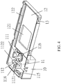
- FIG. 4 is another perspective diagram showing the filter switch device of FIG. 1 .
- FIG. 5 is another perspective diagram showing interior of the filter switch device of FIG. 1 .
- a filter switch device includes the following components.
- a casing 10 provides a first chamber 11 and a second chamber 12 inside.
- the first chamber 11 and the second chamber 12 are connected, and the first chamber 11 has a greater depth than that of the second chamber 12 .
- a bottom side of the first chamber 11 is configured with an axle 111 , a number of first blocks 112 , a number of second blocks 113 , and a pad 114 .
- the first chamber 11 has a left notch 115 and a right notch 116 respectively along two opposing inner walls of the first chamber 11 .
- the first chamber 11 further has a first cushion element 117 and a second cushion element 118 inside.
- the second chamber 12 has a first opening 121 on a bottom side and two troughs 122 respectively along two opposing inner walls of the second chamber 12 .
- an electromagnetic assembly 20 includes a magnetic element 21 , a swing arm 22 , an iron core 23 , a winding seat 24 accommodating the iron core 23 , and a number of windings 25 on the winding seat 24 .
- the iron core 23 , winding seat 24 , and windings 25 are modularized structures.
- the axle 111 threads through the magnetic element 21 .
- Aback end of the swing arm 22 is mounted to a top end of the axle 111 and coupled to the magnetic element 21 .
- a front end of the swing arm 22 has an engaging element 221 .
- the swing arm 22 has two slant sides from the front end to the back end, each configured with an outward protruding bulge 222 .
- the magnetic element 21 is ring-shaped whose inner wall is configured with a number of locking recesses 211 at intervals.
- the back end of the swing arm 22 has an opening 223 .
- the swing arm 22 has a column 224 extended downward from a bottom side opposite to the opening 22 .
- a number of locking elements 2241 are configured at intervals around the column 224 for engaging the locking recesses 211 .
- the engagement between the locking elements 2241 and the locking recesses 211 provides a convenient locking better than adhesive.
- the iron core 23 has a U-like shape with two parallel and opposing arms.
- the windings seat 24 includes two tubes 241 , and the two arms of the iron core 23 respectively thread through the tubes 241 .
- the windings 25 are respectively wound around the tubes 241 .
- the tubes 241 have a first end joined to a first flange 242 , and each tube 241 has a second end joined to a respective second flange 243 .
- the windings 25 are thereby confined between the first flange 242 and the second flanges 243 .
- a positioning block 244 is extended from each second flange 243 opposite to the tubes 241 .
- the iron core 23 is housed in the first chamber 11 .
- the magnetic element 21 is held between the two arms of the iron core 23 , which are in turn are fixed by the first blocks 112 .
- a body of the iron core 23 is disposed on the pad 114 and fixed by the second blocks 113 .
- Each first block 112 and second block 113 respectively has a first hook 1121 and a second hook 1131 for fixing the iron core 23 .
- the first blocks 112 and the second blocks 113 respectively have slant first guiding slopes 1122 and second guiding slopes 1132 . With the first guiding slopes 1122 and second guiding slopes 1132 , the iron core 23 may be embedded inside the first chamber 11 , and fixed by the first blocks 112 and the second blocks 113 .
- the circumference of the winding seat 24 contacts with the inner wall of the first chamber 11 , the first cushion element 117 , the second cushion element 118 , and the second block 113 .
- the positioning blocks 244 also contact with the inner wall of the first chamber 11 . As such, the installation of the iron core 23 may be conducted in an automated manufacturing process for enhanced performance.
- the magnetic element 21 's two sides are respective a positive side and a negative side.
- the iron core 23 's two arms respectively have a concaved section 231 facing each other.
- the concaved sections 231 respectively face the magnetic element 21 's positive side and negative side.
- a first welding pin 251 and a second welding pin 252 are respectively configured on the positioning blocks 244 .
- the windings 25 are respectively connected to the first welding pin 251 and the second welding pin 252 .
- the first welding pin 251 and the second welding pin 252 are connected to a plug 253 .
- the plug 253 is electrically connected to an external power source.
- the windings seat 24 has a modular design.
- the windings 25 are mounted on the windings seat 24 , and the two arms of the iron core 23 are plugged into the winding seat 24 so as to produce electromagnetic force.
- the windings 25 are respectively connected to the first welding pin 251 and the second welding pin 252 , which in turn are connected to the plug 253 .
- a plate 30 has its two opposing edges respectively received by the troughs 122 of the second chamber 12 .
- a filter 31 is disposed on the plate 30 .
- a piece 32 is extended from a lateral edge of the plate 30 . The piece 32 is located above the right notch 116 , and the piece 32 has a limiting hole 321 .
- the swing arm 22 's engaging element 221 runs through the limiting hole 321 .
- the casing 10 further includes a cover 40 sealing the first chamber 11 and the second chamber 12 .
- the cover 40 has second opening 41 corresponding to the first opening 121 .
- the cover 40 has a number of protruding positioning elements 42 arranged in parallel on a bottom side to two opposing sides of the second opening 41 .
- the plate 30 is positioned between the positioning elements 42 .
- a number of first fasteners 43 are arranged at intervals around the cover 40 's circumference.
- a number of second fasteners 13 are arrange at intervals along a circumferential wall of the casing 10 .
- Each first fastener 43 is coupled to a corresponding second fastener 13 so as to withstand external impact.
- the filter switch device of the present embodiment the electromagnetic field produced by the windings 25 after electricity is introduced is expelled by the magnetism from the positive side and the negative side of the magnetic element 21 .
- the magnetic element 21 is turned as well as the swing arm 22 .
- the engaging element 221 moves the plate 30 , and the filter 31 and the first opening 121 are aligned, thereby achieving the filter switch.
- a bulge 222 is against the first cushion element 117 and, when the swing arm 22 is turned, another bulge 222 is against the second cushion element 118 .
- An operation life of the switch arm 22 is extended as its impact is buffered by the second cushion element 118 .
- the filter switch device has a reduced form factor and weight, and therefore it may be employed in various applications.
Landscapes
- Physics & Mathematics (AREA)
- General Physics & Mathematics (AREA)
- Optics & Photonics (AREA)
- Engineering & Computer Science (AREA)
- Multimedia (AREA)
- Signal Processing (AREA)
- Filters And Equalizers (AREA)
- Housings And Mounting Of Transformers (AREA)
Abstract
Description
Claims (10)
Priority Applications (1)
| Application Number | Priority Date | Filing Date | Title |
|---|---|---|---|
| US16/780,908 US11076077B2 (en) | 2019-01-08 | 2020-02-04 | Filter switch device |
Applications Claiming Priority (4)
| Application Number | Priority Date | Filing Date | Title |
|---|---|---|---|
| US16/243,053 US20200218131A1 (en) | 2019-01-08 | 2019-01-08 | Lens screening device |
| TW108212095U TWM588262U (en) | 2019-09-11 | 2019-09-11 | Automatically manufactured infrared filter switcher |
| TW108212095 | 2019-09-11 | ||
| US16/780,908 US11076077B2 (en) | 2019-01-08 | 2020-02-04 | Filter switch device |
Related Parent Applications (1)
| Application Number | Title | Priority Date | Filing Date |
|---|---|---|---|
| US16/243,053 Continuation-In-Part US20200218131A1 (en) | 2019-01-08 | 2019-01-08 | Lens screening device |
Publications (2)
| Publication Number | Publication Date |
|---|---|
| US20200220999A1 US20200220999A1 (en) | 2020-07-09 |
| US11076077B2 true US11076077B2 (en) | 2021-07-27 |
Family
ID=71403570
Family Applications (1)
| Application Number | Title | Priority Date | Filing Date |
|---|---|---|---|
| US16/780,908 Expired - Fee Related US11076077B2 (en) | 2019-01-08 | 2020-02-04 | Filter switch device |
Country Status (1)
| Country | Link |
|---|---|
| US (1) | US11076077B2 (en) |
Families Citing this family (1)
| Publication number | Priority date | Publication date | Assignee | Title |
|---|---|---|---|---|
| CN113339392A (en) * | 2021-07-16 | 2021-09-03 | 北京盈想东方科技股份有限公司 | Fixed T target support arm |
Citations (4)
| Publication number | Priority date | Publication date | Assignee | Title |
|---|---|---|---|---|
| US20050073604A1 (en) * | 2002-10-21 | 2005-04-07 | Takuji Umezu | Light-quantity adjusting apparatus, optical apparatus, and camera |
| US20070291157A1 (en) * | 2006-06-15 | 2007-12-20 | Beijing Ding | Camera with automatic daytime/nighttime feature |
| US20180356283A1 (en) * | 2015-12-03 | 2018-12-13 | Nidec Copal Corporation | Blade drive module, imaging unit provided with blade drive module, and imaging device |
| US20200007730A1 (en) * | 2017-03-23 | 2020-01-02 | Sony Corporation | Interchangeable lens and method for controlling the same, shooting apparatus, and camera system |
-
2020
- 2020-02-04 US US16/780,908 patent/US11076077B2/en not_active Expired - Fee Related
Patent Citations (4)
| Publication number | Priority date | Publication date | Assignee | Title |
|---|---|---|---|---|
| US20050073604A1 (en) * | 2002-10-21 | 2005-04-07 | Takuji Umezu | Light-quantity adjusting apparatus, optical apparatus, and camera |
| US20070291157A1 (en) * | 2006-06-15 | 2007-12-20 | Beijing Ding | Camera with automatic daytime/nighttime feature |
| US20180356283A1 (en) * | 2015-12-03 | 2018-12-13 | Nidec Copal Corporation | Blade drive module, imaging unit provided with blade drive module, and imaging device |
| US20200007730A1 (en) * | 2017-03-23 | 2020-01-02 | Sony Corporation | Interchangeable lens and method for controlling the same, shooting apparatus, and camera system |
Also Published As
| Publication number | Publication date |
|---|---|
| US20200220999A1 (en) | 2020-07-09 |
Similar Documents
| Publication | Publication Date | Title |
|---|---|---|
| US8537226B2 (en) | Voice coil motor and camera module having same | |
| US9793079B2 (en) | Electromagnetic relay | |
| US10184530B2 (en) | Electromagnetic connection device | |
| US7576455B2 (en) | High performance focusing actuator of a voice coil motor | |
| US11530535B2 (en) | Dividing screen structure | |
| US11076077B2 (en) | Filter switch device | |
| CN101872056A (en) | Voice coil motor assembly | |
| CN109031690A (en) | Photographing module | |
| KR20130065594A (en) | Magnetic valve | |
| CN102810968A (en) | Voice coil motor actuator and imaging device | |
| CN101752977A (en) | Voice coil motor | |
| TWI514719B (en) | Voice coil motor and camera module using same | |
| KR101806888B1 (en) | Dual camera module | |
| JP2008026431A (en) | Lens drive device | |
| CN206618891U (en) | Lens driver and the photographic means and electronic equipment for possessing it | |
| TW201328129A (en) | Voice coil motor | |
| CN110970266A (en) | Electromagnetic relay | |
| CN120010085B (en) | Locking mechanism and driving motor thereof | |
| TW201308838A (en) | Voice coil motor | |
| CN100388037C (en) | Lens driving device | |
| KR102500365B1 (en) | Camera module | |
| CN114326003B (en) | Focus moving frame locking mechanism, lens driving device and camera equipment | |
| TWI439016B (en) | Voice coil motor | |
| CN103296854B (en) | Voice coil motor | |
| CN219740509U (en) | Camera module and intelligent wearable device |
Legal Events
| Date | Code | Title | Description |
|---|---|---|---|
| AS | Assignment |
Owner name: FUNDER ELECTRONIC GLOBAL CO., LTD., TAIWAN Free format text: ASSIGNMENT OF ASSIGNORS INTEREST;ASSIGNOR:WENG, WAI-HOW;REEL/FRAME:051706/0085 Effective date: 20191206 |
|
| FEPP | Fee payment procedure |
Free format text: ENTITY STATUS SET TO UNDISCOUNTED (ORIGINAL EVENT CODE: BIG.); ENTITY STATUS OF PATENT OWNER: SMALL ENTITY |
|
| FEPP | Fee payment procedure |
Free format text: ENTITY STATUS SET TO SMALL (ORIGINAL EVENT CODE: SMAL); ENTITY STATUS OF PATENT OWNER: SMALL ENTITY |
|
| STPP | Information on status: patent application and granting procedure in general |
Free format text: DOCKETED NEW CASE - READY FOR EXAMINATION |
|
| STPP | Information on status: patent application and granting procedure in general |
Free format text: NOTICE OF ALLOWANCE MAILED -- APPLICATION RECEIVED IN OFFICE OF PUBLICATIONS |
|
| STPP | Information on status: patent application and granting procedure in general |
Free format text: PUBLICATIONS -- ISSUE FEE PAYMENT RECEIVED |
|
| STPP | Information on status: patent application and granting procedure in general |
Free format text: PUBLICATIONS -- ISSUE FEE PAYMENT VERIFIED |
|
| STCF | Information on status: patent grant |
Free format text: PATENTED CASE |
|
| FEPP | Fee payment procedure |
Free format text: MAINTENANCE FEE REMINDER MAILED (ORIGINAL EVENT CODE: REM.); ENTITY STATUS OF PATENT OWNER: SMALL ENTITY |
|
| LAPS | Lapse for failure to pay maintenance fees |
Free format text: PATENT EXPIRED FOR FAILURE TO PAY MAINTENANCE FEES (ORIGINAL EVENT CODE: EXP.); ENTITY STATUS OF PATENT OWNER: SMALL ENTITY |
|
| STCH | Information on status: patent discontinuation |
Free format text: PATENT EXPIRED DUE TO NONPAYMENT OF MAINTENANCE FEES UNDER 37 CFR 1.362 |
|
| FP | Lapsed due to failure to pay maintenance fee |
Effective date: 20250727 |