JP4854581B2 - Imaging apparatus and control method thereof - Google Patents
Imaging apparatus and control method thereof Download PDFInfo
- Publication number
- JP4854581B2 JP4854581B2 JP2007114505A JP2007114505A JP4854581B2 JP 4854581 B2 JP4854581 B2 JP 4854581B2 JP 2007114505 A JP2007114505 A JP 2007114505A JP 2007114505 A JP2007114505 A JP 2007114505A JP 4854581 B2 JP4854581 B2 JP 4854581B2
- Authority
- JP
- Japan
- Prior art keywords
- period
- diaphragm
- driving
- charge accumulation
- accumulation period
- Prior art date
- Legal status (The legal status is an assumption and is not a legal conclusion. Google has not performed a legal analysis and makes no representation as to the accuracy of the status listed.)
- Expired - Fee Related
Links
Images


Classifications
-
- G—PHYSICS
- G03—PHOTOGRAPHY; CINEMATOGRAPHY; ANALOGOUS TECHNIQUES USING WAVES OTHER THAN OPTICAL WAVES; ELECTROGRAPHY; HOLOGRAPHY
- G03B—APPARATUS OR ARRANGEMENTS FOR TAKING PHOTOGRAPHS OR FOR PROJECTING OR VIEWING THEM; APPARATUS OR ARRANGEMENTS EMPLOYING ANALOGOUS TECHNIQUES USING WAVES OTHER THAN OPTICAL WAVES; ACCESSORIES THEREFOR
- G03B7/00—Control of exposure by setting shutters, diaphragms or filters, separately or conjointly
- G03B7/08—Control effected solely on the basis of the response, to the intensity of the light received by the camera, of a built-in light-sensitive device
- G03B7/091—Digital circuits
- G03B7/097—Digital circuits for control of both exposure time and aperture
-
- H—ELECTRICITY
- H04—ELECTRIC COMMUNICATION TECHNIQUE
- H04N—PICTORIAL COMMUNICATION, e.g. TELEVISION
- H04N23/00—Cameras or camera modules comprising electronic image sensors; Control thereof
- H04N23/60—Control of cameras or camera modules
- H04N23/63—Control of cameras or camera modules by using electronic viewfinders
- H04N23/633—Control of cameras or camera modules by using electronic viewfinders for displaying additional information relating to control or operation of the camera
-
- H—ELECTRICITY
- H04—ELECTRIC COMMUNICATION TECHNIQUE
- H04N—PICTORIAL COMMUNICATION, e.g. TELEVISION
- H04N23/00—Cameras or camera modules comprising electronic image sensors; Control thereof
- H04N23/60—Control of cameras or camera modules
- H04N23/665—Control of cameras or camera modules involving internal camera communication with the image sensor, e.g. synchronising or multiplexing SSIS control signals
-
- H—ELECTRICITY
- H04—ELECTRIC COMMUNICATION TECHNIQUE
- H04N—PICTORIAL COMMUNICATION, e.g. TELEVISION
- H04N23/00—Cameras or camera modules comprising electronic image sensors; Control thereof
- H04N23/60—Control of cameras or camera modules
- H04N23/67—Focus control based on electronic image sensor signals
- H04N23/673—Focus control based on electronic image sensor signals based on contrast or high frequency components of image signals, e.g. hill climbing method
-
- H—ELECTRICITY
- H04—ELECTRIC COMMUNICATION TECHNIQUE
- H04N—PICTORIAL COMMUNICATION, e.g. TELEVISION
- H04N23/00—Cameras or camera modules comprising electronic image sensors; Control thereof
- H04N23/70—Circuitry for compensating brightness variation in the scene
- H04N23/73—Circuitry for compensating brightness variation in the scene by influencing the exposure time
-
- H—ELECTRICITY
- H04—ELECTRIC COMMUNICATION TECHNIQUE
- H04N—PICTORIAL COMMUNICATION, e.g. TELEVISION
- H04N23/00—Cameras or camera modules comprising electronic image sensors; Control thereof
- H04N23/70—Circuitry for compensating brightness variation in the scene
- H04N23/75—Circuitry for compensating brightness variation in the scene by influencing optical camera components
Description
本発明は、デジタルカメラ等の撮像装置における露出制御技術に関するものである。 The present invention relates to an exposure control technique in an imaging apparatus such as a digital camera.
カメラは、撮影時に被写体を捕らえるためのファインダーを備えている。ファインダーには大きく分けて光学的なものと電子式のものがある。 The camera is equipped with a viewfinder for capturing a subject during shooting. There are two types of viewfinders: optical and electronic.
光学ファインダーには、一眼レフカメラのように撮影時に使用する光学レンズを通過した光をミラーで屈曲させるものや、撮影用の光学レンズを通さずにファインダー窓から被写体を覗き見るものがある。 Some optical viewfinders, such as single-lens reflex cameras, use a mirror to bend light that has passed through an optical lens that is used during shooting, and others can look through a viewfinder window without passing through an optical lens for shooting.
電子式ビューファインダーは、近年のコンパクトデジタルスチルカメラに多く採用されている方式である。具体的には、撮影用レンズを通過した光を、撮影時に使用するCCDなどの撮像素子にて受光し、光電変換した画像信号をLCDなどの画像表示装置に逐次表示する構成となっている。この構成では、ファインダー時と撮影時で同じ撮像素子を使用することができるため、ファインダー視野率100%を実現することが容易となり、視野率の点では光学ファインダーに比べてメリットが大きいとされている。 The electronic viewfinder is a method that is widely used in recent compact digital still cameras. Specifically, the light passing through the photographing lens is received by an image pickup device such as a CCD used for photographing, and the photoelectrically converted image signal is sequentially displayed on an image display device such as an LCD. In this configuration, since the same image sensor can be used for the viewfinder and for shooting, it is easy to achieve 100% viewfinder field of view, and it is said that there is a greater merit than the optical viewfinder in terms of field of view. Yes.
撮像素子は、静止画撮影用途、ファインダー用途に留まらない。即ち、被写体へのピント合わせを自動で行うAF(Auto Focus Control)用途、被写体の明るさを適正に制御するAE(Auto Exposure Control)用途にも使用される。AF時、AE時にはそれぞれ、撮像素子を測距センサー、測光センサーとして使用することとなる。このように撮像素子は、ファインダーとしてユーザーに被写体像をモニタリングさせるとともに、AF、AEといった撮影準備作業も両立させて行う場合がある。 The image sensor is not limited to still image shooting and viewfinder applications. That is, it is also used for AF (Auto Focus Control) for automatically focusing on a subject and for AE (Auto Exposure Control) for appropriately controlling the brightness of a subject. During AF and AE, the image sensor is used as a distance measuring sensor and a photometric sensor, respectively. As described above, the image sensor may allow the user to monitor the subject image as a finder and may also perform shooting preparation work such as AF and AE.
カメラには露出を決める要素として、入射光量を調節する絞り、露光する時間を調節するシャッターが備えられている。デジタルカメラの場合、撮像素子で受光した後に撮像素子から読み出した信号レベルを増幅/減衰させるゲイン制御もある。特に、絞り機構は露出を変更するだけでなく、絞り径により被写界深度が変わることを考慮しなければならない。絞りは、絞り径が大きいほど被写界深度が浅くなり、絞り径が小さいほど被写界深度が深くなる。この光学的な現象を考慮し、AF時には絞りを開放寄りにして静止画撮影時よりも深度が浅い状態でピント合わせをしておくことで、深度による静止画撮影時のピントずれを防止できることが知られている。 The camera is provided with an aperture for adjusting the amount of incident light and a shutter for adjusting the exposure time as factors that determine the exposure. In the case of a digital camera, there is also gain control for amplifying / attenuating a signal level read from the image sensor after receiving light by the image sensor. In particular, the aperture mechanism must not only change the exposure but also consider that the depth of field changes depending on the aperture diameter. As the aperture diameter increases, the depth of field decreases, and as the aperture diameter decreases, the depth of field increases. Taking this optical phenomenon into consideration, focusing can be performed with the aperture close to the open position during AF and with a shallower depth than when shooting still images. Are known.
AF、AE機能を備えたカメラでは、ユーザーが撮影を指示するレリーズボタンが2段階となっているのが一般的となっている。即ち、ボタンを浅く押下することでAF、AEが行われて静止画撮影のためのピント合わせと露出合わせが行われ、ボタンを深く押下することで撮影が開始される仕組みとなっているものが一般的である。以後、レリーズボタンを浅く押下することをSW1動作、深く押下することをSW2動作と呼ぶ。 In cameras equipped with AF and AE functions, the release button for the user to instruct photographing is generally in two stages. That is, AF and AE are performed by pressing the button shallowly to perform focusing and exposure adjustment for still image shooting, and shooting is started by pressing the button deeply. It is common. Hereinafter, pressing the release button shallowly is referred to as SW1 operation, and pressing deeply is referred to as SW2 operation.
SW1動作においてAFする際、前述のようにAF時には絞りを開放寄りに制御する。AF完了後は、静止画撮影で使用する絞り径にあらかじめ制御しておくことで、SW2押下後に絞り駆動する必要がなくなり、レリーズタイムラグの短縮に効果がある。このように、絞りはメカ機構であるため駆動にはある程度の時間がかかることを前提とし、それを考慮した提案がなされている(特許文献1参照)。 When performing AF in the SW1 operation, as described above, the aperture is controlled to close to the open position during AF. After the AF is completed, the aperture diameter used for still image shooting is controlled in advance, so that it is not necessary to drive the aperture after the SW2 is pressed, which is effective in shortening the release time lag. As described above, since the diaphragm is a mechanical mechanism, it is premised that driving takes a certain amount of time, and a proposal has been made in consideration thereof (see Patent Document 1).
さらに、絞り制御にはある程度の時間がかかることから、前述のようにファインダー用途としてユーザーが被写体像をモニタリングしている最中に絞りを駆動すると、絞りが動く途中の劣化画像が画像表示装置に出力されてしまうという問題があった。これを防ぐために絞り駆動中には画像表示装置の画像更新は行わず、絞り駆動前の画像を表示するとした提案がなされている(特許文献2参照)。しかしこの提案では画像更新が一旦停止したように見えるため、被写体の動きをとらえるファインダーとしての用途には適していない解決策である。 Furthermore, since the aperture control takes a certain amount of time, as described above, when the user drives the aperture while the subject image is being monitored as a finder application, a deteriorated image in the middle of moving the aperture is displayed on the image display device. There was a problem of being output. In order to prevent this, an image display apparatus is not updated during aperture driving, and an image before aperture driving is displayed (see Patent Document 2). However, in this proposal, since the image update seems to be temporarily stopped, it is a solution that is not suitable for use as a finder for capturing the movement of the subject.
また、絞りを制御する際の画質劣化をファインダーに見せない、あるいは動画に記録されないように、条件によっては絞りを動かさなくするという提案もなされている(特許文献3参照)。しかしこの提案では、絞りを動かさないようにすることで被写体輝度への追従範囲が狭くなり、AE性能が低下してしまうという問題があった。
上記のように、静止画撮影用の撮像素子を、ファインダー、AF、AE、動画撮影など様々な用途で単独あるいは同時に使用し、かつ、それぞれの要件に応じて絞りを駆動していくことで、レスポンス良く良好な撮影画像が得られる。しかしカメラ使用者が、ファインダー用途として被写体像を捕らえている最中に、絞り駆動による画質劣化が発生してしまう場合があり、その場合、電子ファインダー性能を大きく損なってしまうという問題があった。 As mentioned above, by using the image sensor for still image shooting alone or simultaneously for various applications such as viewfinder, AF, AE, movie shooting, etc., and driving the diaphragm according to each requirement, A good captured image with good response can be obtained. However, while the camera user is capturing a subject image for use in a viewfinder, image quality deterioration may occur due to aperture driving. In this case, there is a problem that the electronic viewfinder performance is greatly impaired.
従って、本発明は上述した課題に鑑みてなされたものであり、その目的は、ファインダー性能やAE性能を低下させることなく、絞りを駆動する際に発生する画質劣化を抑制することである。 Therefore, the present invention has been made in view of the above-described problems, and an object of the present invention is to suppress image quality degradation that occurs when driving a diaphragm without degrading the finder performance or the AE performance.
上述した課題を解決し、目的を達成するために、本発明に係わる撮像装置は、被写体像を光電変換して電荷の蓄積を行う撮像素子を備える撮像手段と、前記撮像素子に入射する光量を調節する絞りの絞り値を設定する設定手段と、前記撮像素子の駆動タイミングを調節することにより前記撮像素子の電荷蓄積期間の長さを調整する調整手段と、前記設定手段により設定された絞り値に基づいて前記絞りを駆動させる際に、前記絞りの駆動期間の少なくとも一部と前記撮像素子の電荷蓄積期間とが重なるか否かを判断する判断手段と、を有し、前記調整手段は、前記判断手段により前記絞りの駆動期間の少なくとも一部と前記撮像素子の電荷蓄積期間とが重なると判断された場合、前記絞りを駆動させる直前の電荷蓄積期間である第1の電荷蓄積期間における露光量と、前記絞りの駆動期間と少なくとも一部が重なる電荷蓄積期間である第2の電荷蓄積期間における露光量とが略一致するように、前記第2の電荷蓄積期間の長さを絞り駆動後の絞り値に対応した電荷蓄積期間の長さと異ならせることを特徴とする。 In order to solve the above-described problems and achieve the object, an imaging apparatus according to the present invention includes an imaging unit including an imaging element that photoelectrically converts a subject image and accumulates charges, and an amount of light incident on the imaging element. Setting means for setting the aperture value of the aperture to be adjusted; adjusting means for adjusting the length of the charge accumulation period of the image sensor by adjusting the drive timing of the image sensor; and the aperture value set by the setting means And determining means for determining whether at least a part of the driving period of the diaphragm overlaps with the charge accumulation period of the image sensor when driving the diaphragm based on If a charge storage period of at least a portion and the imaging device driving period of the diaphragm the is determined to overlap by said determination means, the first charge蓄a charge accumulation period immediately before driving the diaphragm The exposure amount in the period, so that the exposure amount and substantially coincide in the second charge accumulation period is a charge accumulation period of the drive period and at least partially overlap said aperture, the length of the second charge accumulation period The length is different from the length of the charge accumulation period corresponding to the aperture value after aperture driving .
また、本発明に係わる撮像装置は、被写体像を光電変換して電荷の蓄積を行う撮像素子を備える撮像手段と、前記撮像素子に入射する光量を調節する絞りの絞り値を設定する設定手段と、前記撮像手段から出力される画像信号に対するゲインを制御するゲイン制御手段と、前記設定手段により設定された絞り値に基づいて前記絞りを駆動させる際に、前記絞りの駆動期間の少なくとも一部と前記撮像素子の電荷蓄積期間とが重なるか否かを判断する判断手段と、を有し、前記ゲイン制御手段は、前記判断手段により前記絞りの駆動期間の少なくとも一部と前記撮像素子の電荷蓄積期間とが重なると判断された場合、前記絞りを駆動させる直前の電荷蓄積期間である第1の電荷蓄積期間における露光量と、前記絞りの駆動期間と少なくとも一部が重なる電荷蓄積期間である第2の電荷蓄積期間における露光量との差分を補償するように、前記第2の電荷蓄積期間に電荷蓄積された画像信号に対するゲインを制御することを特徴とする。 The image pickup apparatus according to the present invention includes an image pickup unit including an image pickup device that photoelectrically converts a subject image and accumulates charges, and a setting unit that sets an aperture value of a stop that adjusts the amount of light incident on the image pickup device. A gain control unit that controls a gain for an image signal output from the imaging unit , and at least a part of a driving period of the aperture when driving the aperture based on the aperture value set by the setting unit; Determining means for determining whether or not the charge accumulation period of the image sensor overlaps, and the gain control means determines whether the gain control means stores at least a part of the driving period of the diaphragm and the charge accumulation of the image sensor. If where the period is determined to overlap, and the exposure amount in the first charge accumulation period is a charge accumulation period immediately before driving the diaphragm, and the diaphragm driving period at least a portion To compensate for the difference between the exposure amount in the second charge accumulation period is a charge accumulation period which overlaps, and controlling the gain for the second charge accumulation period in the charge stored image signal.
また、本発明に係わる撮像装置は、被写体像を光電変換して電荷の蓄積を行う撮像素子を備える撮像手段と、前記撮像素子に入射する光量を調節する絞りの絞り値を設定する設定手段と、前記撮像素子の駆動タイミングを調節することにより前記撮像素子の電荷蓄積期間の長さを調整する調整手段と、前記撮像手段から出力される画像信号に対するゲインを制御するゲイン制御手段と、前記設定手段により設定された絞り値に基づいて前記絞りを駆動させる際に、前記絞りの駆動期間の少なくとも一部と前記撮像素子の電荷蓄積期間とが重なるか否かを判断する判断手段と、を有し、前記判断手段により前記絞りの駆動期間の少なくとも一部と前記撮像素子の電荷蓄積期間とが重なると判断された場合、前記絞りを駆動させる直前の電荷蓄積期間である第1の電荷蓄積期間に電荷蓄積された画像信号のレベルと、前記絞りの駆動期間と少なくとも一部が重なる電荷蓄積期間である第2の電荷蓄積期間に電荷蓄積された画像信号のレベルとが略一致するように、前記調整手段により前記第2の電荷蓄積期間の長さを絞り駆動後の絞り値に対応した電荷蓄積期間の長さと異ならせるとともに、前記ゲイン制御手段により前記第2の電荷蓄積期間に電荷蓄積された画像信号に対するゲインを制御することを特徴とする。 The image pickup apparatus according to the present invention includes an image pickup unit including an image pickup device that photoelectrically converts a subject image and accumulates charges, and a setting unit that sets an aperture value of a stop that adjusts the amount of light incident on the image pickup device. Adjusting means for adjusting the length of the charge accumulation period of the image sensor by adjusting the drive timing of the image sensor, gain control means for controlling the gain for the image signal output from the image sensor, and the setting Determining means for determining whether or not at least a part of the driving period of the diaphragm overlaps the charge accumulation period of the image sensor when the diaphragm is driven based on the aperture value set by the means. and, if a charge storage period of at least a portion and the imaging device driving period of the diaphragm the is determined to overlap by said determination means, charge storage immediately before driving the diaphragm Between the level of the image signal accumulated in the first charge accumulation period that is between and the second charge accumulation period that is a charge accumulation period that overlaps at least partly with the driving period of the diaphragm. The length of the second charge accumulation period is made different from the length of the charge accumulation period corresponding to the aperture value after driving the diaphragm so that the level substantially matches the level, and the gain control means makes the first charge accumulation period different from the length of the charge accumulation period . It is characterized in that the gain with respect to the image signal in which charge is accumulated during the charge accumulation period of 2 is controlled.
本発明によれば、ファインダー性能やAE性能を低下させることなく、絞りを駆動する際に発生する画質劣化を抑制することが可能となる。 According to the present invention, it is possible to suppress deterioration in image quality that occurs when driving the aperture without degrading the viewfinder performance or AE performance.
以下、本発明の好適な一実施形態について、添付図面を参照して詳細に説明する。 Hereinafter, a preferred embodiment of the present invention will be described in detail with reference to the accompanying drawings.
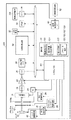
図1は、本発明の撮像装置の一実施形態であるデジタルカメラのシステム構成を示すブロック図である。 FIG. 1 is a block diagram showing a system configuration of a digital camera which is an embodiment of an imaging apparatus of the present invention.
デジタルカメラ100は、被写体像を結像させるためのレンズ10を備えている。図1ではレンズ10は1枚として表現しているが、複数枚のレンズから構成されたレンズユニットを搭載することも可能である。また、レンズ駆動回路42によりレンズ位置を撮影光軸に沿って前後に動かすことで焦点を調節したり、画角を調節することも可能である。さらに、手ブレ補正回路40によりレンズ10を駆動し、手ブレをキャンセルする方向に光軸を移動させることで光学的な手ブレ補正を行う構成とすることも可能である。図1ではレンズを駆動することで手ブレ補正を実現しているが、撮像素子16(本実施形態ではCCD)を移動させることで同様に手ブレを補正することも可能である。レンズ10を含む鏡筒部を繰り出し及び繰り込みさせる方式とし、カメラ未使用時の本体体積を小さくして携帯性を向上させることが可能である。レンズ10を通過した光は絞り14により、その光量を調節することができる。
The
システム制御回路60は、絞り制御情報を絞り駆動回路26に伝達することで、絞り14の開き量を制御することが可能である。システム制御回路60から絞り駆動回路26への制御情報伝達は、シリアル通信やパルス信号などがあり、絞り駆動回路26の仕様に合わせて適した手段をとる。絞り14は、複数枚の羽根から構成された虹彩絞りや、あらかじめ、板に様々な径で穴を打ち抜いた丸絞りがある。システム制御回路60はこれらの絞り14と絞り駆動回路26を用い、被写体輝度が高い場合は絞りを絞って光量を落とすように制御し、被写体輝度が低い場合は絞りを開放にして光を多く取り込むように制御することが可能である。
The
システム制御回路60は、メカニカルシャッターの制御情報をメカニカルシャッター駆動回路28に伝達することで、メカニカルシャッター12を制御することが可能である。静止画撮影時の露光時間は、メカニカルシャッター12の開閉時間により決定され、この時間はシステム制御回路60が時間を判断し、メカニカルシャッター駆動回路28に指示を出す。
The
レンズ10、メカニカルシャッター12、絞り14を通過した光は撮像素子16で受光される。システム制御回路60は、撮像素子制御信号をTG(Timing Generator)24に伝達することで、撮像素子16を制御することができる。システム制御回路60からTG24への制御情報伝達は、シリアル通信やパラレルバス通信などがあり、TG24の仕様に合わせて適した手段をとる。TG24は、システム制御回路60から受信した制御情報をもとに撮像素子16を駆動する。撮像素子16は素子への露光と、露光した信号の読み出し作業を周期的に行っており、この作業はTG24からの駆動信号を基準に行われる。撮像素子16で露光した信号のうち、特定のラインや特定の領域のみを読み出してくることが可能である。これは、TG24から出力される読み出し制御パルスにより読み出し方を変更することで実現できる。システム制御回路60は状況に応じて最適な読み出し方式を決定し、TG24に指示する。例えば、静止画撮影時は高解像度が要求されるため撮像素子16の全画素の信号を読み出し、電子ファインダー時や動画撮影時は30fps/60fpsなどの高いフレームレートが要求されるため特定のラインだけ間引いて読み出す、といった使い分けを行う。
Light that has passed through the
またTG24は、撮像素子16の露光時間を制御することが可能である。任意のタイミングで、素子がチャージした電荷を開放するように、TG24から撮像素子16へ駆動信号を出すことでこれを可能としている。
The
撮像素子16から読み出された画像信号は、CDS回路(Correlated Double Sampler)18を通過する。CDS回路18は相関二重サンプリング方式により画像信号のノイズ成分を除去することを主な役割とする。
The image signal read from the
その後、画像信号はPGA回路(Programmable Gain Amplifier)20により、画像信号レベルを減衰/増幅することができる。システム制御回路60は、増幅レベルをPGA20に伝達することで、増幅量を制御することができる。システム制御回路60からPGA20への制御情報伝達は、シリアル通信やパラレルバス通信などがあり、PGA20の仕様に合わせて適した手段をとる。通常、撮像素子16の露出を適正にするには、絞り14で撮像素子16への露光量を適切に設定すると共に、シャッターにより露光時間を適切に設定することで実現される。しかし、PGA20で画像信号を減衰/増幅することで、擬似的に画像信号の露出を変える役割を担うことができる。これは、絞りやシャッター速度と並ぶ撮影時の露出条件の一つとして、感度という概念でユーザーに機能提供することが可能である。
Thereafter, the image signal level can be attenuated / amplified by a PGA circuit (Programmable Gain Amplifier) 20. The
画像信号はA/D変換回路(Analog/Digital Converter)22にてアナログ信号からデジタル信号へ変換される。デバイスにより、デジタル信号のビット幅は10ビット、12ビット、14ビットなどがあり、後段の画像処理回路50は、複数種類のビット幅に対応可能である。図1では、CDS回路18、PGA回路20、A/D変換回路22をそれぞれ別のブロックとして表現しているが、一つのICパッケージにこれらの機能を搭載したものを採用することも可能である。
The image signal is converted from an analog signal to a digital signal by an A / D conversion circuit (Analog / Digital Converter) 22. Depending on the device, the bit width of the digital signal may be 10 bits, 12 bits, 14 bits, etc., and the
A/D変換回路22でデジタル化された画像データは画像処理回路50へ入力される。画像処理回路50は複数のブロックから構成され、さまざまな機能を実現している。
The image data digitized by the A /
撮像素子16はカラーフィルターを通して各画素ごとに特定の色成分を抽出するのが一般的である。A/D変換回路22からの画像データは撮像素子16の画素及びカラーフィルター配置に対応したデータ形式になっている。そのため、輝度成分のみを評価して露出制御を行う自動露出制御(AE:Auto Exposure Control)で使用するには適さない形式である。画像処理回路50は、画像信号から色情報を排除し、輝度情報のみを抜き出す機能を備えている。さらに、画像処理回路50は、撮像素子16から読み出された信号の周波数成分のみを抜き出す機能を備え、自動ピント合わせ制御(AF:Auto Focus)時に使用することができる。また、画像処理回路50は、A/D変換回路22によりデジタル化された画像データのレベルの増減、画像の色効果などを操作する機能を備え、撮影画像の画質を調節するという役割も担っている。
The
A/D変換回路22でデジタル化された画像データは画像処理回路50へ入力されると同時に、一時記憶メモリ30に記憶することができる。一旦、一時記憶メモリ30に記憶した画像データは再度読み出すことができ、システム制御回路60から画像データを参照したり、読み出した画像データを画像処理回路50に入力することが可能である。さらに、画像処理回路50で画像処理した画像データを一時記憶メモリ30に書き戻したり、システム制御回路60から任意のデータを書き込むことも可能である。
The image data digitized by the A /
LCDなどの画像表示装置108に画像データを出力する場合、画像処理回路50で画像処理を行った画像データをVRAM34上に展開しておき、それをD/A変換回路36にてアナログ信号に変換して画像表示装置108に表示する。電子ファインダーを実現する場合は、撮像素子16から読み出される連続した画像を順次画像表示装置108に表示更新していくことで可能となる。ここで、VRAM34の画像を1コマあるいは複数コマのみ更新しないようにすることが可能である。絞り駆動中(絞りが動いている途中)の画質劣化を画像表示装置108に出力しないようにするには、この手段を用いることとなる。VRAM34上に画像データを展開する際、1つの画像データを画像表示装置108に最も大きくなるように、または複数の画像をマルチ画面表示するように、など、様々な表示形態に対応するようにVRAM34上に展開することができる。
When outputting image data to the
画像表示装置108には、画像だけでなく任意の情報を単独、もしくは画像と共に表示することが可能である。カメラの状態表示や、ユーザーが選択あるいはカメラが決定したシャッター速度や絞り値、感度情報などの文字情報や、画像処理回路50で測定した輝度分布のようなグラフも表示可能である。情報の表示位置、表示色も任意に選択可能である。これら様々な情報を表示することで、ユーザーインターフェースを実現することが可能となる。また、画像表示装置108には、画像記憶媒体82に記憶されている画像データを表示することも可能である。画像データが圧縮されている場合、圧縮伸張回路32で伸張し、VRAM34にデータを展開する。このデータをD/A変換回路34でアナログ信号に変換して出力する。
The
図2は、デジタルカメラ100の外観を示す図である。カメラ前面にはレンズ10が配置され、被写体像をとらえることができる。レンズ10の同一面にストロボユニット90が配置されている。主被写体が暗い場合にストロボユニット90を発光させることで十分な光量を得ることができ、暗い中でも速いシャッター速度を保ち、好適な画像を得ることができる。図2では、レンズ10とストロボユニット90が同一面に配置されているが、これに限定されるものではなく、ストロボ光が主被写体に直接当たることを避けるために、ストロボがカメラ上方に向くように配置することも可能である。
FIG. 2 is a diagram illustrating an appearance of the
カメラ背面には、画像表示装置108が配置されている。前述したように、画像表示装置108には画像のみならず、文字情報やグラフなどを表示することができ、ユーザーとインターフェースをとる重要な部材となっている。近年、デジタルカメラでは電子ビューファインダー(EVF:Electrical ViewFinder)が主流となっており、画像表示装置108に出力される連続画像を参照することで被写体を捕らえ、ファインダーとして使用している。また、従来からの光学ファインダー106を併設する構成とすることも可能である。電子ビューファインダーは、高い視野率を実現し易い、画像表示装置108の大きさによっては被写体を大きく見易い、撮影画像とファインダー画像の画角差(パララックス)が無い、などのメリットがある。その反面、撮像素子16や画像表示装置108を動作させるための電力が必要となり、電池の消耗が懸念される。このため、電池の消耗を避けて多くの撮影枚数が望まれる場合には、電子ビューファインダー機能をOFFし、光学ファインダー106を使用するという使い方も可能である。
An
モード切替スイッチ110は、静止画撮影モード、動画撮影モード、再生モードなどのカメラ動作モードを切り替えることができる。図2では、数モードを切り替え可能な部材として表現しているが、撮影する特定のシーンに最適化した、風景撮影モードや人物撮影モードなどの多くの静止画モードを備えることも可能である。
The
パラメータ選択スイッチ151,153,157,159により、撮影時の撮影条件の選択や、撮影画像再生時のページ送り、カメラの動作設定全般などをユーザーが選択することができる。さらに前述の電子ファインダーのON/OFFを選択することもできる。また、画像表示装置108は画像を表示すると共に、タッチパネルとして入力装置となる構成とすることもできる。
The parameter selection switches 151, 153, 157, and 159 allow the user to select shooting conditions at the time of shooting, page turning at the time of playing back a shot image, general camera operation settings, and the like. Furthermore, ON / OFF of the above-described electronic viewfinder can be selected. Further, the
カメラ上部にレリーズボタン104が配置されている。レリーズボタン104は一つの操作部材であるが、ボタンを浅く押下する場合(SW1動作)と深く押下する場合(SW2動作)の2段階の押下操作を実現可能である。自動露出制御や自動ピント制御を行うカメラの場合、レリーズボタン104を浅く押すことで撮影準備として自動露出制御とピント制御が行われ、深く押すことで静止画撮影を行う操作が実現可能である。
A
自動露出制御は、モード切替スイッチ110で選択されている撮影モードで好適な露出を得るように動作する。撮影モードには、ポートレートモードや風景モード、夜景モード、といった特定の被写体に特化したものや、オートモードといった汎用的なモードがある。また、シャッター速度優先モードや絞り優先モードなど、撮影時のシャッター速度や絞り値をあらかじめユーザーが指定しておくモードもある。これらのモードでは、PGA20で設定する撮影感度を自動で好適に選択設定することや、あらかじめユーザーが感度を指定することが可能である。ユーザーがあらかじめ感度を指定する際、撮影感度を上げるほど画像信号のS/Nが低下するため、画質を優先したいユーザーは低感度を選択することが想定される。
The automatic exposure control operates so as to obtain a suitable exposure in the shooting mode selected by the
図3は、レリーズボタン104が押下された際のシーケンスを示す図である。ここでは、カメラの動作と、そのときの絞り径の変化を主に示す。また、各カメラの動作時に使用するプログラム線図のうちEVF線図を図4に、AF線図を図5に、静止画線図を図6に示す。プログラム線図とは、そのカメラ動作時に取り得る絞り、シャッター、ゲインの組み合わせを定義した一種のテーブル情報であり、被写体輝度に応じてこのプログラム線図を用いて露出決定を行う。ただし、ここで示したプログラム線図の内容はあくまで一例であり、プログラム線図の内容は機器ごとに任意に変更可能である。
FIG. 3 is a diagram showing a sequence when the
カメラ動作状態のうちEVF状態(Electrical ViewFinder)212は、画像表示装置108に被写体像を連続出力して電子ビューファインダーを実現している状態であり、撮影前の待機状態と位置づけられる。このEVF状態212では、図4に示すEVF用のプログラム線図を使用して絞り、シャッターなどの露出制御値を求め、その値に制御している。撮像素子16にCCDを使用する場合、CCD特有のスミア現象を軽減させるために、早めに、絞り径を閉方向に制御するプログラム線図にしている。また、図4では、絞りをF2.8、F4.0、F5.6、F8.0の四値しか取りえないように離散的な絞り制御を行う線図としている。その理由は次のようなものである。高い絞り精度を実現する際にはある程度の絞り駆動速度が必要となる場合があるが、その駆動速度で絞りを駆動すると駆動音が鳴る場合がある。このため、被写体輝度の変化に対してAEが追従する際に駆動音が鳴る回数を限定するために、図4のように逆Z型を積み上げたようなプログラム線図を設計する場合がある。ただし、これはそのメカ絞り機構の精度に依存する内容であり、低速駆動で駆動音が抑えられ、さらに高い精度も実現できるメカ絞りの場合、図4のようなプログラム線図とする必要は無い。即ち、F2.8〜F8.0まで縦方向にリニアな線図を設計することも可能である。
An EVF state (Electrical ViewFinder) 212 in the camera operation state is a state in which an electronic viewfinder is realized by continuously outputting subject images to the
EVF状態(ライブビュー動作)212からユーザーによりレリーズボタン104が浅く押されてSW1がONになると、カメラ動作がAF(Auto Focus)状態214に切り替わる。CCDなどの撮像素子16をAFの測距センサーとして使用する場合、次のようなAF方式が知られている。即ち、レンズ10を撮影光軸に沿って動かしながらそれぞれのレンズ位置で、撮像素子16から読み出された画像信号を元に画像処理回路50にて画像の周波数成分を抽出し、周波数の高いレンズ位置を探していくスキャンAF方式である。このAFスキャン時に使用するプログラム線図は、図5のように絞り径は開放位置を多用する線図が設計される。これは、絞り径により被写界深度が変化するという光学的な現象を考慮したもので、絞り開放の深度が浅い状態でピント位置を合わせておけば、AF後にどの絞り径で撮影しようとも、深度の変化がピント位置に悪影響を及ぼすことが少なくなるからである。仮に、AFスキャン時に深度が深い状態でピント合わせをし、その後絞り径を開いて静止画撮影する場合、絞り径を開くことで深度が浅くなり、ピントずれが発生する懸念がある。逆に、静止画撮影で使用する絞り径が既に決定している場合は、AF時に図5のプログラム線図を使用せず、静止画用の絞り径を使用してスキャンAFするシーケンスとすることも可能である。
When the user presses the
AFが終了すると、SW1保持状態216となる。この状態は、静止画撮影用のピントおよび露出を決定し、レリーズボタン104が深く押されてSW2がONされればすぐに撮影可能な状態である。図3のシーケンスでは、SW2押下後の撮影タイムラグを短くすることを目的に、AF後に、静止画撮影で使用する絞り径にあらかじめ絞り制御しておくシーケンスを示している。このようにすることでSW2押下後に絞りが駆動することがなく、撮りたい瞬間にすぐ撮影できるようになる。
When AF ends, the
このようなカメラ動作状態が遷移していく撮影シーケンスが実現された場合、絞り駆動が発生する箇所が複数出てくる。一つは、EVF状態からAF状態に遷移する際にプログラム線図が図4から図5に変更され、絞り駆動が発生する場合である。もう一つは、AF状態からSW1保持状態に遷移する場合である。例として、露出値Ev=12の場合の絞り値及びシャッター速度の変化は次のようになる。ただしこの例では、図4のEVF線図、図5のAF線図、図6の静止画線図において、感度Svは同一と仮定する。 When such a shooting sequence in which the camera operation state transitions is realized, a plurality of locations where aperture driving occurs. One is a case where the program diagram is changed from FIG. 4 to FIG. 5 when the EVF state transitions to the AF state, and diaphragm driving occurs. The other case is a transition from the AF state to the SW1 holding state. As an example, changes in aperture value and shutter speed when the exposure value Ev = 12 are as follows. However, in this example, it is assumed that the sensitivity Sv is the same in the EVF diagram of FIG. 4, the AF diagram of FIG. 5, and the still image diagram of FIG.
EVF線図 : F8.0、1/60秒 (302)
AF線図 : F2.8、1/500秒 (304)
静止画線図 : F4.0、1/250秒 (306)
このように、カメラ動作状態に応じて露出値Ev=12を保ったまま絞りとシャッター速度が変化するが、その際、絞りはメカ機構であるためその駆動にはある程度の時間がかかってしまう。この絞り駆動中の様子が撮像素子16にて露光されてしまい、結果的にファインダーとして使用している画像表示装置108に絞りによる画質劣化の様子が出力されてしまう。レリーズボタン104の押下時はユーザーに撮影する意思があり、撮影に集中したいところであるが、このような絞り駆動による露出変動と言う画質劣化がファインダーに見えてしまうため、集中力が削がれたり、最悪、被写体を撮り逃してしまう場合がある。
EVF diagram: F8.0, 1/60 second (302)
AF diagram: F2.8, 1/500 second (304)
Still image diagram: F4.0, 1/250 seconds (306)
As described above, the aperture and the shutter speed change while maintaining the exposure value Ev = 12 according to the camera operation state. However, since the aperture is a mechanical mechanism, it takes a certain amount of time to drive the aperture. The state during driving of the aperture is exposed by the
図7は、絞り駆動時に発生する露出変動による画質劣化を説明するための詳しいタイミング図である。ここでは例として、Av3(F2.8)、Tv6(1/60秒)から、Av4(F4.0)、Tv5(1/30秒)に露出を変化させる場合を示す。この変化は、次のような式で示される。 FIG. 7 is a detailed timing chart for explaining image quality deterioration due to exposure fluctuations that occur during aperture driving. Here, as an example, the case where the exposure is changed from Av3 (F2.8) and Tv6 (1/60 seconds) to Av4 (F4.0) and Tv5 (1/30 seconds) is shown. This change is expressed by the following equation.
制御前の露出 : Av3+Tv6=Ev9 (422)
制御後の露出 : Av4+Tv5=Ev9 (424)
即ち、Ev=9を保ったまま、絞りとシャッター速度を変化させることとなる。
Exposure before control: Av3 + Tv6 = Ev9 (422)
Exposure after control: Av4 + Tv5 = Ev9 (424)
That is, the aperture and the shutter speed are changed while Ev = 9 is maintained.
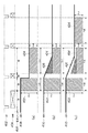
VD402は撮像素子16の垂直同期信号である。この垂直同期信号内で、SUBパルス404の出力量を調節することで、撮像素子16の駆動タイミングが制御され、電子シャッター406の開閉(電荷蓄積の時間の制御、即ち電子シャッター制御)が実現される。SUBパルス404は撮像素子に蓄積された電荷を捨てる役割を果たしており、電荷を捨てることで露光を行わない、すなわちシャッターを閉じていると考えることができる。SUBパルスを出力しないようにすることで電荷が蓄積され続け、これをシャッターが開いている(電子シャッター開時間)と考えることができる。このようにSUBパルス404にて電子シャッターの開閉が実現される。
図7(a)は、Av3、Tv6からAv4、Tv5へ変化する際に、絞り駆動時間がゼロだった場合のタイミング図である。SUBパルス404はVD402に同期して出力量を制御可能であるため、あるVDとあるVDで、電子シャッター速度を瞬時に変えることが可能である。絞りもVD単位で瞬時に変化することが可能な場合、絞り駆動408のように、Av3からAv4までタイムラグなく移動できる。この場合、Av3、Tv6での露光量422、Av4、Tv5での露光量424は、露光量(斜線部の面積であり電荷蓄積量でもある)としては同一となり、露出値Ev=9を保ったまま、絞りとシャッターを制御することができている。
FIG. 7A is a timing chart when the aperture driving time is zero when changing from Av3, Tv6 to Av4, Tv5. Since the output amount of the
しかし、実際には絞り駆動にはある程度の時間がかかってしまうため、現実的には図7(b)のように絞り駆動410にタイムラグが生じてしまう。このとき、絞り駆動により露光オーバー分426が生じてしまい、この分が、露出変動としてビューファインダーに表示されてしまう。
However, since the diaphragm drive actually takes a certain amount of time, in reality, a time lag occurs in the
そこで本実施形態では、図7(c)のように、絞り駆動中であっても露出値Evが保たれ露光量(斜線部の面積)に変化がないようにする。具体的には、露光量の変動を抑制するため、シャッター速度412を本来の目標値であるTv=5から若干速めのシャッター速度に補正し、露光オーバー分が相殺されるようにする。こののち、絞り駆動が完了後、シャッター速度を本来の目標値であるTv=5に設定する。このように制御することで、絞り駆動時の露出変動による画質劣化がビューファインダーに表示されるのを防ぐことができる。
Therefore, in the present embodiment, as shown in FIG. 7C, the exposure value Ev is maintained even during the aperture driving so that the exposure amount (area of the hatched portion) does not change. Specifically, in order to suppress fluctuations in the exposure amount, the
このように、絞り駆動による露光量の変動をシャッターで補正する以外に、ゲインを用いて補正する方式を取ることも可能である。図8(c)に、絞り駆動による露光変動量を抑制するためにゲインで相殺する場合を示す。ゲインによる画像信号の増幅/減衰は、撮像素子16から読み出される信号全体に作用させることができる。そのため、図8(c)のように、露光量426、424のレベルを462、464で示すように全体的に下げ、撮像素子16から読み出された撮像信号レベルで露光量に変化がないように制御する。これにより、電子シャッターで補正したのと同様な効果を得ることができ、絞り駆動時の露出変動による画質劣化がビューファインダーに表示されるのを防ぐことができる。
In this way, in addition to correcting fluctuations in exposure amount due to aperture driving with a shutter, it is possible to adopt a method of correcting using gain. FIG. 8C shows a case where the gain is canceled out in order to suppress the exposure fluctuation amount due to the aperture driving. Amplification / attenuation of the image signal by the gain can be applied to the entire signal read from the
図9は、デジタルカメラ100を起動してからの動作を示すフローチャートである。
FIG. 9 is a flowchart showing operations after the
カメラの電源投入スイッチ102 が押下された後、撮影に必要な各種デバイスの初期化を行う(ステップS101)。レンズ10を含む鏡筒が繰り出し方式の場合は鏡筒繰り出し処理を行い、画像処理回路50などカメラ内部のLSIやCPUの初期化、起動も行う。
After the power-on
画像表示装置108をカメラファインダーとして使用するために被写体のライブ画像を出力する場合、ライブ画像の露出を適正に制御するためにライブビュー用のコンティニュアスAE動作を開始する(ステップS103)。コンティニュアスAE開始後は、被写体の輝度変化に応じて露出が適正に制御され続ける。ピント制御は、常に主被写体にピントを合わせつづけるコンティニュアスモードや、撮影準備時にのみピントを合わせるワンショットモードを備える場合がある。そのため、ライブ画像を出力する際に常にピントを合わせるわけではなく、所定位置にフォーカスレンズを駆動するのみとする場合もあり、図9では記載を省いている。
When a live image of a subject is output in order to use the
ライブ画像を出力する準備が整った後、画像表示装置108 にライブ画像出力を開始する(ステップS105)。ユーザーは画像表示装置108に表示されたライブ画像を見て被写体のフレーミングを行い、電子ビューファインダーとして使用することができる。画像表示装置108にライブ画像を出力しないようにユーザーが指示することも可能で、その場合は光学ファインダー106をカメラファインダーとして使用することになる。
After the preparation for outputting the live image is completed, live image output is started on the image display device 108 (step S105). The user looks at the live image displayed on the
ユーザーにファインダー機能を提供した後、レリーズボタン104の押下の受付を許可する。まず、露出とピントを合わせるためのSW1押下があるかどうかを検出する(ステップS107)。SW1押下を検出した場合、図10で示したSW1処理(ステップS109)が実行され、被写体に応じて露出とピントが決定される。SW1処理の完了後、SW2ボタンがONされるか(ステップS113)、SW1ボタンがOFFされて撮影を中断するか(ステップS111)を検出する。SW2押下を検出した場合は静止画撮影を行い(ステップS115)、SW1がOFFされた場合は、元の撮影待機状態に戻る。
After providing the user with the finder function, the user is permitted to press the
図10は、SW1押下後の処理を示すフローチャートである。 FIG. 10 is a flowchart showing processing after SW1 is pressed.
SW1押下直前まではライブビュー用のコンティニュアスAEが動作しており(ステップS103)、図4のEVF用プログラム線図から求めた絞り、シャッター、ゲイン値に露出が設定されている。このSW1押下時点で設定されている絞り値AvEVF、シャッター速度TvEVF、ゲインGainEVFと、そのときの撮像素子16の駆動により決定される感度SvEVFを用い、被写体輝度Bvを計測する(ステップS131)。
The live view continuous AE operates until immediately before SW1 is pressed (step S103), and the aperture, shutter, and gain values obtained from the EVF program diagram of FIG. 4 are set to exposure. The subject brightness Bv is measured using the aperture value AvEVF, the shutter speed TvEVF, the gain GainEVF, and the sensitivity SvEVF determined by the driving of the
Bv=AvEVF+TvEVF−GainEVF−SvEVF
次に、AF動作用の露出を図5のAF用プログラム線図から求めるが、まずはプログラム線図を引くための露出値EvAFを求める。先ほど求めた被写体輝度Bvと、AF時の撮像素子16の駆動により決定される感度SvAFを使用する。
Bv = AvEVF + TvEVF−GainEVF−SvEVF
Next, the exposure for AF operation is obtained from the AF program diagram of FIG. 5. First, an exposure value EvAF for drawing the program diagram is obtained. The previously determined subject brightness Bv and the sensitivity SvAF determined by driving the
EvAF=Bv+SvAF
このように求めたEvAFを用い、プログラム線図からAF用の絞り値、シャッター速度、ゲイン値を求める(ステップS133)。
EvAF = Bv + SvAF
Using the EvAF obtained in this way, the aperture value, shutter speed, and gain value for AF are obtained from the program diagram (step S133).
EvAF=AvAF+TvAF−GainAF
このあとAF用の露出に制御し(ステップS135)、この露出にて被写体に応じてピント合わせ処理が行われる(ステップS137)。
EvAF = AvAF + TvAF-GainAF
Thereafter, the exposure for AF is controlled (step S135), and the focusing process is performed according to the subject at this exposure (step S137).
AF終了後、静止画撮影用露出と(ステップS139)、SW1保持用露出(ステップS141)の2つの露出を決定する。静止画撮影用露出は、図6の静止画撮影用プログラム線図から絞り、シャッター、ゲインの組み合わせを求める。まずはプログラム線図を引くための露出値EvCapを求める。先ほど求めた被写体輝度Bvと、静止画撮影時の感度SvCapを使用する。 After the AF is completed, two exposures are determined: a still image shooting exposure (step S139) and a SW1 holding exposure (step S141). The exposure for still image shooting calculates | requires the combination of an aperture, a shutter, and a gain from the program diagram for still image shooting of FIG. First, an exposure value EvCap for drawing a program diagram is obtained. The subject luminance Bv obtained earlier and the sensitivity SvCap at the time of still image shooting are used.
EvCap=Bv+SvCap
このように求めたEvCapを用い、プログラム線図を引く。
EvCap = Bv + SvCap
A program diagram is drawn using the EvCap thus obtained.
EvCap=AvCap+TvCap−GainCap
続いて、SW1保持用露出を決定する場合も、まずは先ほど求めた被写体輝度Bvと、SW1保持時の撮像素子16の駆動により決定される感度SvLockを使用し、露出値EvLockを求める。
EvCap = AvCap + TvCap−GainCap
Subsequently, when determining the exposure for holding SW1, the exposure value EvLock is first obtained by using the subject brightness Bv obtained earlier and the sensitivity SvLock determined by driving the
EvLock=Bv+SvLock
EvLockから絞り値、シャッター速度、ゲイン値を求める際、プログラム線図を用いずに次の手順で決定していく。まず絞り値は、SW2押下後のタイムラグ短縮を目的に、絞り値をAvCapに決定する。次に、EvLockを実現できるようなシャッター速度TvLockを選択する。被写体輝度が明るい、もしくは暗いために、選択したシャッター速度TvLockではEvLockが実現できない場合、ゲインによりEvLockが実現できるようにGainLockを決定する。
EvLock = Bv + SvLock
When obtaining the aperture value, shutter speed, and gain value from EvLock, they are determined by the following procedure without using the program diagram. First, the aperture value is determined to be AvCap for the purpose of shortening the time lag after pressing SW2. Next, a shutter speed TvLock that can realize EvLock is selected. If EvLock cannot be realized at the selected shutter speed TvLock because the subject brightness is bright or dark, GainLock is determined so that EvLock can be realized by gain.
決定したSW1保持用の露出に制御する前に、レリーズボタン104が深く押されてSW2がONされているかを検出する(ステップS143)。ユーザーにより既にSW2がONされて撮影開始が指示されている場合、SW1保持用の露出に制御して画像表示装置にライブ画像を出力する必要がないため、SW1保持用の露出制御を行わずにSW1完了とする。SW2が押下されていない場合は、SW1保持状態でファインダー機能を実現するために、SW1保持用の露出に制御する(ステップS145)。
Before controlling to the determined exposure for holding SW1, it is detected whether the
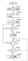
図11は、露出制御時の動作を示すフローチャートである。このフロー実行時には、現在設定されている絞り値Av1、シャッター速度Tv1、ゲイン値Gain1と、次に設定する目標となる絞り値Av2、シャッター速度Tv2、ゲイン値Gain2が明確になっているものとする。また、フロー中で用いている変数は、図12のタイミング図に記載した各値を意味している。 FIG. 11 is a flowchart showing an operation during exposure control. When this flow is executed, it is assumed that the currently set aperture value Av1, shutter speed Tv1, gain value Gain1, and target aperture value Av2, shutter speed Tv2, and gain value Gain2 to be set next are clear. . Moreover, the variable used in the flow means each value described in the timing chart of FIG.
本実施形態は、電子ファインダーに出力される画像に対し、絞りによる画質劣化を改善するものであるため、まずは電子ファインダー出力しているかどうかを判定する(ステップS151)。電子ファインダーがOFFされている場合、光学ファインダー106を使用していると判断し、絞り駆動による露光変動補正を行わないようにする。また、電子ファインダーがONされている場合であっても、絞り駆動が露光期間に重なっていないと判断された場合は補正する必要がないため、補正しない(ステップS153)。補正しない場合は目標絞り値Av2、シャッター速度Tv2、ゲイン値Gain2にそのまま露出制御する(ステップS155)。
In this embodiment, since the image quality deterioration due to the diaphragm is improved with respect to the image output to the electronic viewfinder, it is first determined whether or not the electronic viewfinder is output (step S151). When the electronic viewfinder is turned off, it is determined that the
絞り駆動が露光期間に重なるかどうかの判定は、絞り駆動時間IrisMoveTimeと、シャッター閉時間ShutterCloseTimeの差であるIrisNoiseTimeで行う。IrisNoiseTimeが正の値を持っている時は、絞り駆動が露光期間に重なっていると判断できる。絞り駆動時間IrisMoveTimeは絞り駆動量(Av2−Av1) と絞り駆動速度IrisSpeedから算出し、シャッター閉時間は目標シャッター速度での露光時間ExpTime2と垂直同期信号周期VDTimeから算出することができる。 Whether or not the aperture driving overlaps the exposure period is determined by IrisNoiseTime which is the difference between the aperture driving time IrisMoveTime and the shutter closing time ShutterCloseTime. When IrisNoiseTime has a positive value, it can be determined that the aperture drive overlaps the exposure period. The aperture drive time IrisMoveTime can be calculated from the aperture drive amount (Av2-Av1) and the aperture drive speed IrisSpeed, and the shutter close time can be calculated from the exposure time ExpTime2 at the target shutter speed and the vertical synchronization signal cycle VDTime.
IrisMoveTime=(Av2−Av1)÷IrisSpeed
ShutterCloseTime=VDTime−ExpTime2
次に、露出制御前後と、絞り駆動時の露出変動分の露光量(図12における斜線部の面積)を算出する(ステップS157、159、161)。
IrisMoveTime = (Av2-Av1) ÷ IrisSpeed
ShutterCloseTime = VDTime-ExpTime2
Next, the exposure amount (area of the hatched portion in FIG. 12) before and after the exposure control and the exposure fluctuation at the time of aperture driving is calculated (steps S157, 159, 161).
露出制御前の露光量は、
Area1=Value1×ExpTime1
となる(ステップS157)。Av値、Tv値は、log圧縮した単位系で表現されているため、log解凍するために2のべき乗したものをValue*、ExpTime* として計算する。また、Valueは、露出制御後のValue2を基準としてValue1を表現している。
The exposure before exposure control is
Area1 = Value1 × ExpTime1
(Step S157). Since the Av value and the Tv value are expressed in a log-compressed unit system, in order to decompress the log, a power of 2 is calculated as Value * and ExpTime *. Value expresses Value1 with reference to Value2 after exposure control.
露出制御後の露光量は、
Area2=Value2×ExpTime2
となる(ステップS159)。絞り駆動による露光変動がない場合には、露出制御前後の露光量Area1とArea2の面積が等しいはずである。
The amount of exposure after exposure control is
Area2 = Value2 × ExpTime2
(Step S159). When there is no exposure fluctuation due to aperture driving, the areas of exposure amounts Area1 and Area2 before and after exposure control should be equal.
絞り駆動による露光変動分は、
IrisNoiseArea=IrisNoiseValue×IrisNoiseTime÷2
となる(ステップS161)。IrisNoiseValueは、目標シャッター速度Tv2に制御した際の、露光開始時点での絞り変動値を示している。また、ここでは絞り駆動が目標絞り値までリニアに制御できるものとしている。さらに、絞り駆動がシャッター閉タイミングと同期して制御可能なものとしている。しかし絞りによってはこの限りではなく、その場合、IrisNoiseAreaの算出方法を絞り駆動特性や、駆動開始遅れ時間に応じて変更することが可能である。
The exposure fluctuation due to aperture drive is
IrisNoiseArea = IrisNoiseValue × IrisNoiseTime ÷ 2
(Step S161). IrisNoiseValue indicates the aperture variation value at the start of exposure when the target shutter speed Tv2 is controlled. Here, it is assumed that the aperture drive can be linearly controlled to the target aperture value. Further, the aperture driving can be controlled in synchronization with the shutter closing timing. However, this is not limited to this depending on the diaphragm. In this case, the calculation method of IrisNoiseArea can be changed according to the diaphragm drive characteristics and the drive start delay time.
各露光量の算出後、それぞれの面積の関係から、絞りによる露光変動分が補正できているかチェックする(ステップS163)。 After the calculation of each exposure amount, it is checked whether the exposure fluctuation due to the aperture can be corrected from the relationship of the respective areas (step S163).
RefArea1とRefArea2+IrisNoiseAreaを比較し、RefArea2+IrisNoiseAreaのほうが大きい場合、絞りによる露光変動分が補正できていないと判断する。そして、シャッター速度を一定量だけ補正方向に変化させる(ステップS171)。その後、再度RefArea2 とIrisNoiseValue を再計算し(ステップS159、161)、RefAreaとの比較を行う(ステップS163)。このように、RefArea2+IrisNoiseAreaの値が、RefArea1と同等の露光量になるまでシャッター速度を補正していく。 RefArea1 and RefArea2 + IrisNoiseArea are compared. If RefArea2 + IrisNoiseArea is larger, it is determined that the exposure fluctuation due to the aperture cannot be corrected. Then, the shutter speed is changed in the correction direction by a certain amount (step S171). Thereafter, RefArea2 and IrisNoiseValue are recalculated again (steps S159 and 161) and compared with RefArea (step S163). In this way, the shutter speed is corrected until the value of RefArea2 + IrisNoiseArea reaches an exposure amount equivalent to RefArea1.
補正用のShutterCloseTimeが決定されたなら、垂直同期信号VDTimeとの差から補正用露光時間ExpTime2’を算出し、さらにTv2’を補正用シャッター速度とする(ステップS165)。 If the correction ShutterCloseTime is determined, the correction exposure time ExpTime2 'is calculated from the difference from the vertical synchronization signal VDTime, and Tv2' is set as the correction shutter speed (step S165).
ExpTime2’=VDTime−ShutterCloseTime
Tv2’=−log2(ExpTime2’)
決定した補正用シャッター速度Tv2’を用い、目標絞り値Av2、目標ゲイン値Gain2と共に、露出制御を行う(ステップS167)。この露出制御時に、Tv2’により絞り駆動による露光変動分がキャンセルされ、ファインダーへ劣化画像が出力されることを防ぐことができる。その後絞り駆動が完了した後、シャッター速度を本来の目標値であるTv2に制御し、一連の補正処理が完了する(ステップS169)。
ExpTime2 '= VDTime-ShutterCloseTime
Tv2 '=-log 2 (ExpTime2')
Using the determined correction shutter speed Tv2 ′, exposure control is performed together with the target aperture value Av2 and the target gain value Gain2 (step S167). At the time of this exposure control, exposure variation due to aperture driving is canceled by Tv2 ′, and it is possible to prevent a deteriorated image from being output to the viewfinder. Thereafter, after the aperture driving is completed, the shutter speed is controlled to Tv2 which is the original target value, and a series of correction processing is completed (step S169).
図11のフローチャートでは、ステップS165の処理でシャッター速度を補正して絞り駆動による露光変動分をキャンセルしようとしている。しかし、別の形態として、ゲイン値を使用して露光変動分をキャンセルする場合もある。その場合は、露光面積IrisNoiseAreaの縦方向のValue値を補正するものとしてフロー演算を行い、求めたValue値をゲイン値に置き換えることで、ゲイン値による補正が可能となる。 In the flowchart of FIG. 11, the shutter speed is corrected by the process of step S165 to cancel the exposure fluctuation due to aperture driving. However, as another form, there is a case where the exposure fluctuation is canceled using the gain value. In that case, correction by the gain value can be performed by performing a flow calculation on the assumption that the vertical value of the exposure area IrisNoiseArea is corrected and replacing the obtained value with a gain value.
このような実施形態にて、絞り駆動による露光変動分を補正し、質の高い電子ファインダーを提供することが可能となる。 In such an embodiment, it is possible to provide a high-quality electronic viewfinder by correcting the exposure fluctuation due to aperture driving.
(他の実施形態)
また、各実施形態の目的は、次のような方法によっても達成される。すなわち、前述した実施形態の機能を実現するソフトウェアのプログラムコードを記録した記憶媒体(または記録媒体)を、システムあるいは装置に供給する。そして、そのシステムあるいは装置のコンピュータ(またはCPUやMPU)が記憶媒体に格納されたプログラムコードを読み出し実行する。この場合、記憶媒体から読み出されたプログラムコード自体が前述した実施形態の機能を実現することになり、そのプログラムコードを記憶した記憶媒体は本発明を構成することになる。また、コンピュータが読み出したプログラムコードを実行することにより、前述した実施形態の機能が実現されるだけでなく、本発明には次のような場合も含まれる。すなわち、プログラムコードの指示に基づき、コンピュータ上で稼働しているオペレーティングシステム(OS)などが実際の処理の一部または全部を行い、その処理によって前述した実施形態の機能が実現される。
(Other embodiments)
The object of each embodiment is also achieved by the following method. That is, a storage medium (or recording medium) in which a program code of software that realizes the functions of the above-described embodiments is recorded is supplied to the system or apparatus. Then, the computer (or CPU or MPU) of the system or apparatus reads and executes the program code stored in the storage medium. In this case, the program code itself read from the storage medium realizes the functions of the above-described embodiments, and the storage medium storing the program code constitutes the present invention. Further, by executing the program code read by the computer, not only the functions of the above-described embodiments are realized, but the present invention includes the following cases. That is, based on the instruction of the program code, an operating system (OS) running on the computer performs part or all of the actual processing, and the functions of the above-described embodiments are realized by the processing.
さらに、次のような場合も本発明に含まれる。すなわち、記憶媒体から読み出されたプログラムコードが、コンピュータに挿入された機能拡張カードやコンピュータに接続された機能拡張ユニットに備わるメモリに書き込まれる。その後、そのプログラムコードの指示に基づき、その機能拡張カードや機能拡張ユニットに備わるCPUなどが実際の処理の一部または全部を行い、その処理によって前述した実施形態の機能が実現される。 Furthermore, the following cases are also included in the present invention. That is, the program code read from the storage medium is written in a memory provided in a function expansion card inserted into the computer or a function expansion unit connected to the computer. Thereafter, based on the instruction of the program code, the CPU or the like provided in the function expansion card or function expansion unit performs part or all of the actual processing, and the functions of the above-described embodiments are realized by the processing.
本発明を上記記憶媒体に適用する場合、その記憶媒体には、先に説明した手順に対応するプログラムコードが格納されることになる。 When the present invention is applied to the above storage medium, the storage medium stores program codes corresponding to the procedure described above.
10 レンズ
12 メカニカルシャッター
14 絞り
16 撮像素子
18 CDS回路
20 PGA
22 A/D変換回路
24 TG
26 絞り駆動回路
28 メカニカルシャッター駆動回路
50 画像処理回路
34 VRAM
32 圧縮伸張回路
36 D/A変換回路
60 システム制御回路
70 カメラ操作部
108 画像表示装置
DESCRIPTION OF
22 A /
26
32 Compression / Expansion Circuit 36 D /
Claims (16)
前記撮像素子に入射する光量を調節する絞りの絞り値を設定する設定手段と、
前記撮像素子の駆動タイミングを調節することにより前記撮像素子の電荷蓄積期間の長さを調整する調整手段と、
前記設定手段により設定された絞り値に基づいて前記絞りを駆動させる際に、前記絞りの駆動期間の少なくとも一部と前記撮像素子の電荷蓄積期間とが重なるか否かを判断する判断手段と、を有し、
前記調整手段は、前記判断手段により前記絞りの駆動期間の少なくとも一部と前記撮像素子の電荷蓄積期間とが重なると判断された場合、前記絞りを駆動させる直前の電荷蓄積期間である第1の電荷蓄積期間における露光量と、前記絞りの駆動期間と少なくとも一部が重なる電荷蓄積期間である第2の電荷蓄積期間における露光量とが略一致するように、前記第2の電荷蓄積期間の長さを絞り駆動後の絞り値に対応した電荷蓄積期間の長さと異ならせることを特徴とする撮像装置。 An image pickup means including an image pickup device that photoelectrically converts a subject image and accumulates charges;
Setting means for setting an aperture value of an aperture for adjusting the amount of light incident on the image sensor;
Adjusting means for adjusting the length of the charge accumulation period of the image sensor by adjusting the drive timing of the image sensor;
Determining means for determining whether or not at least a part of the driving period of the diaphragm and a charge accumulation period of the imaging element overlap when driving the diaphragm based on the aperture value set by the setting means; Have
The adjusting means is a first charge accumulation period immediately before driving the diaphragm when it is determined by the determining means that at least a part of the drive period of the diaphragm overlaps with the charge accumulation period of the imaging element . The length of the second charge accumulation period is such that the exposure amount in the charge accumulation period and the exposure amount in the second charge accumulation period, which is a charge accumulation period at least partially overlapping with the driving period of the diaphragm, substantially coincide. An image pickup apparatus, wherein the length is different from a length of a charge accumulation period corresponding to an aperture value after aperture driving .
前記撮像素子に入射する光量を調節する絞りの絞り値を設定する設定手段と、
前記撮像手段から出力される画像信号に対するゲインを制御するゲイン制御手段と、
前記設定手段により設定された絞り値に基づいて前記絞りを駆動させる際に、前記絞りの駆動期間の少なくとも一部と前記撮像素子の電荷蓄積期間とが重なるか否かを判断する判断手段と、を有し、
前記ゲイン制御手段は、前記判断手段により前記絞りの駆動期間の少なくとも一部と前記撮像素子の電荷蓄積期間とが重なると判断された場合、前記絞りを駆動させる直前の電荷蓄積期間である第1の電荷蓄積期間における露光量と、前記絞りの駆動期間と少なくとも一部が重なる電荷蓄積期間である第2の電荷蓄積期間における露光量との差分を補償するように、前記第2の電荷蓄積期間に電荷蓄積された画像信号に対するゲインを制御することを特徴とする撮像装置。 An image pickup means including an image pickup device that photoelectrically converts a subject image and accumulates charges;
Setting means for setting an aperture value of an aperture for adjusting the amount of light incident on the image sensor;
Gain control means for controlling the gain for the image signal output from the imaging means;
Determining means for determining whether or not at least a part of the driving period of the diaphragm and a charge accumulation period of the imaging element overlap when driving the diaphragm based on the aperture value set by the setting means; Have
The gain control means is a first charge accumulation period immediately before driving the diaphragm when it is determined by the determination means that at least a part of the drive period of the diaphragm overlaps with the charge accumulation period of the imaging element . The second charge accumulation period so as to compensate for the difference between the exposure amount in the charge accumulation period and the exposure amount in the second charge accumulation period, which is a charge accumulation period that overlaps at least partly with the driving period of the diaphragm. An image pickup apparatus that controls a gain for an image signal in which electric charges are accumulated.
前記撮像素子に入射する光量を調節する絞りの絞り値を設定する設定手段と、
前記撮像素子の駆動タイミングを調節することにより前記撮像素子の電荷蓄積期間の長さを調整する調整手段と、
前記撮像手段から出力される画像信号に対するゲインを制御するゲイン制御手段と、
前記設定手段により設定された絞り値に基づいて前記絞りを駆動させる際に、前記絞りの駆動期間の少なくとも一部と前記撮像素子の電荷蓄積期間とが重なるか否かを判断する判断手段と、を有し、
前記判断手段により前記絞りの駆動期間の少なくとも一部と前記撮像素子の電荷蓄積期間とが重なると判断された場合、前記絞りを駆動させる直前の電荷蓄積期間である第1の電荷蓄積期間に電荷蓄積された画像信号のレベルと、前記絞りの駆動期間と少なくとも一部が重なる電荷蓄積期間である第2の電荷蓄積期間に電荷蓄積された画像信号のレベルとが略一致するように、前記調整手段により前記第2の電荷蓄積期間の長さを絞り駆動後の絞り値に対応した電荷蓄積期間の長さと異ならせるとともに、前記ゲイン制御手段により前記第2の電荷蓄積期間に電荷蓄積された画像信号に対するゲインを制御することを特徴とする撮像装置。 An image pickup means including an image pickup device that photoelectrically converts a subject image and accumulates charges;
Setting means for setting an aperture value of an aperture for adjusting the amount of light incident on the image sensor;
Adjusting means for adjusting the length of the charge accumulation period of the image sensor by adjusting the drive timing of the image sensor;
Gain control means for controlling the gain for the image signal output from the imaging means;
Determining means for determining whether or not at least a part of the driving period of the diaphragm and a charge accumulation period of the imaging element overlap when driving the diaphragm based on the aperture value set by the setting means; Have
If it is determined by the determination means that at least a part of the driving period of the diaphragm overlaps with the charge storage period of the image sensor, the charge is charged in a first charge storage period that is a charge storage period immediately before driving the diaphragm. The adjustment is performed so that the level of the accumulated image signal substantially coincides with the level of the image signal accumulated during the second charge accumulation period which is a charge accumulation period at least partially overlapping with the driving period of the diaphragm. The length of the second charge accumulation period is made different from the length of the charge accumulation period corresponding to the aperture value after the diaphragm drive by means, and the charge is accumulated in the second charge accumulation period by the gain control means. An imaging apparatus that controls a gain for a signal.
前記撮像素子に入射する光量を調節する絞りの絞り値を設定する設定ステップと、
前記撮像素子の駆動タイミングを調節することにより前記撮像素子の電荷蓄積期間の長さを調整する調整ステップと、
前記設定ステップで設定された絞り値に基づいて前記絞りを駆動させる際に、前記絞りの駆動期間の少なくとも一部と前記撮像素子の電荷蓄積期間とが重なるか否かを判断する判断ステップと、を有し、
前記調整ステップでは、前記判断ステップで前記絞りの駆動期間の少なくとも一部と前記撮像素子の電荷蓄積期間とが重なると判断された場合、前記絞りを駆動させる直前の電荷蓄積期間である第1の電荷蓄積期間における露光量と、前記絞りの駆動期間と少なくとも一部が重なる電荷蓄積期間である第2の電荷蓄積期間における露光量とが略一致するように、前記第2の電荷蓄積期間の長さを絞り駆動後の絞り値に対応した電荷蓄積期間の長さと異ならせることを特徴とする撮像装置の制御方法。 A method for controlling an image pickup apparatus having an image pickup unit including an image pickup element that photoelectrically converts a subject image and accumulates charges,
A setting step of setting the aperture value of the aperture to adjust the amount of light incident before Symbol imaging device,
An adjusting step of adjusting the length of the charge accumulation period of the image pickup device by adjusting the drive timing of the previous SL imaging device,
A determination step of determining whether or not at least a part of a drive period of the diaphragm overlaps a charge accumulation period of the image sensor when driving the diaphragm based on the aperture value set in the setting step; Have
In the adjustment step, if it is determined in the determination step that at least a part of the driving period of the diaphragm overlaps with the charge storage period of the imaging device, the first charge storage period immediately before driving the diaphragm The length of the second charge accumulation period is such that the exposure amount in the charge accumulation period and the exposure amount in the second charge accumulation period, which is a charge accumulation period at least partially overlapping with the driving period of the diaphragm, substantially coincide. control method for an imaging apparatus according to claim Rukoto be different from the length of the charge storage period corresponding to the aperture value after driving squeezing of.
前記撮像素子に入射する光量を調節する絞りの絞り値を設定する設定ステップと、
前記撮像手段から出力される画像信号に対するゲインを制御するゲイン制御ステップと、
前記設定ステップで設定された絞り値に基づいて前記絞りを駆動させる際に、前記絞りの駆動期間の少なくとも一部と前記撮像素子の電荷蓄積期間とが重なるか否かを判断する判断ステップと、を有し、
前記ゲイン制御ステップでは、前記判断ステップで前記絞りの駆動期間の少なくとも一部と前記撮像素子の電荷蓄積期間とが重なると判断された場合、前記絞りを駆動させる直前の電荷蓄積期間である第1の電荷蓄積期間における露光量と、前記絞りの駆動期間と少なくとも一部が重なる電荷蓄積期間である第2の電荷蓄積期間における露光量との差分を補償するように、前記第2の電荷蓄積期間に電荷蓄積された画像信号に対するゲインを制御することを特徴とする撮像装置の制御方法。 A method for controlling an image pickup apparatus having an image pickup unit including an image pickup element that photoelectrically converts a subject image and accumulates charges,
A setting step of setting the aperture value of the aperture to adjust the amount of light incident before Symbol imaging device,
A gain control step of controlling the gain for the image signal output from the pre-Symbol imaging means,
A determination step of determining whether or not at least a part of a drive period of the diaphragm overlaps a charge accumulation period of the image sensor when driving the diaphragm based on the aperture value set in the setting step; Have
In the gain control step, when it is determined in the determination step that at least a part of the drive period of the diaphragm overlaps with the charge storage period of the imaging device, the first charge storage period immediately before driving the diaphragm. The second charge accumulation period so as to compensate for the difference between the exposure amount in the charge accumulation period and the exposure amount in the second charge accumulation period, which is a charge accumulation period that overlaps at least partly with the driving period of the diaphragm. A method for controlling an imaging apparatus, comprising: controlling a gain with respect to an image signal in which electric charges are accumulated.
前記撮像素子に入射する光量を調節する絞りの絞り値を設定する設定ステップと、
前記撮像素子の駆動タイミングを調節することにより前記撮像素子の電荷蓄積期間の長さを調整する調整ステップと、
前記撮像手段から出力される画像信号に対するゲインを制御するゲイン制御ステップと、
前記設定ステップで設定された絞り値に基づいて前記絞りを駆動させる際に、前記絞りの駆動期間の少なくとも一部と前記撮像素子の電荷蓄積期間とが重なるか否かを判断する判断ステップと、を有し、
前記判断ステップで前記絞りの駆動期間の少なくとも一部と前記撮像素子の電荷蓄積期間とが重なると判断された場合、前記絞りを駆動させる直前の電荷蓄積期間である第1の電荷蓄積期間に電荷蓄積された画像信号のレベルと、前記絞りの駆動期間と少なくとも一部が重なる電荷蓄積期間である第2の電荷蓄積期間に電荷蓄積された画像信号のレベルとが略一致するように、前記調整ステップで前記第2の電荷蓄積期間の長さを絞り駆動後の絞り値に対応した電荷蓄積期間の長さと異ならせるとともに、前記ゲイン制御ステップで前記第2の電荷蓄積期間に電荷蓄積された画像信号に対するゲインを制御することを特徴とする撮像装置の制御方法。 A method for controlling an image pickup apparatus having an image pickup unit including an image pickup element that photoelectrically converts a subject image and accumulates charges,
A setting step of setting the aperture value of the aperture to adjust the amount of light incident before Symbol imaging device,
An adjusting step of adjusting the length of the charge accumulation period of the image pickup device by adjusting the drive timing of the previous SL imaging device,
A gain control step of controlling the gain for the image signal output from the pre-Symbol imaging means,
A determination step of determining whether or not at least a part of a drive period of the diaphragm overlaps a charge accumulation period of the image sensor when driving the diaphragm based on the aperture value set in the setting step; Have
If it is determined in the determination step that at least a part of the drive period of the diaphragm overlaps with the charge storage period of the image sensor, the charge is charged in a first charge storage period that is a charge storage period immediately before driving the stop. The adjustment is performed so that the level of the accumulated image signal substantially coincides with the level of the image signal accumulated during the second charge accumulation period which is a charge accumulation period at least partially overlapping with the driving period of the diaphragm. In the step, the length of the second charge accumulation period is made different from the length of the charge accumulation period corresponding to the aperture value after the diaphragm drive, and the charge is accumulated in the second charge accumulation period in the gain control step. A control method for an imaging apparatus, characterized by controlling a gain for a signal.
Priority Applications (3)
| Application Number | Priority Date | Filing Date | Title |
|---|---|---|---|
| JP2007114505A JP4854581B2 (en) | 2007-04-24 | 2007-04-24 | Imaging apparatus and control method thereof |
| US12/105,579 US7783189B2 (en) | 2007-04-24 | 2008-04-18 | Imaging apparatus and control method thereof |
| US12/836,475 US7925153B2 (en) | 2007-04-24 | 2010-07-14 | Imaging apparatus and control method thereof |
Applications Claiming Priority (1)
| Application Number | Priority Date | Filing Date | Title |
|---|---|---|---|
| JP2007114505A JP4854581B2 (en) | 2007-04-24 | 2007-04-24 | Imaging apparatus and control method thereof |
Publications (3)
| Publication Number | Publication Date |
|---|---|
| JP2008271412A JP2008271412A (en) | 2008-11-06 |
| JP2008271412A5 JP2008271412A5 (en) | 2010-06-17 |
| JP4854581B2 true JP4854581B2 (en) | 2012-01-18 |
Family
ID=39887099
Family Applications (1)
| Application Number | Title | Priority Date | Filing Date |
|---|---|---|---|
| JP2007114505A Expired - Fee Related JP4854581B2 (en) | 2007-04-24 | 2007-04-24 | Imaging apparatus and control method thereof |
Country Status (2)
| Country | Link |
|---|---|
| US (2) | US7783189B2 (en) |
| JP (1) | JP4854581B2 (en) |
Families Citing this family (34)
| Publication number | Priority date | Publication date | Assignee | Title |
|---|---|---|---|---|
| JP4854581B2 (en) * | 2007-04-24 | 2012-01-18 | キヤノン株式会社 | Imaging apparatus and control method thereof |
| US8032019B2 (en) * | 2008-05-21 | 2011-10-04 | Panasonic Corporation | Camera body and imaging apparatus |
| JP2010063088A (en) * | 2008-08-08 | 2010-03-18 | Sanyo Electric Co Ltd | Imaging apparatus |
| JP5132497B2 (en) * | 2008-09-16 | 2013-01-30 | キヤノン株式会社 | IMAGING DEVICE AND IMAGING DEVICE CONTROL METHOD |
| CN101819369B (en) * | 2009-02-27 | 2014-03-26 | 松下电器产业株式会社 | Camera body and imaging apparatus |
| KR101589013B1 (en) * | 2009-03-16 | 2016-01-27 | 삼성전자주식회사 | Method and apparatus for controlling flash emission |
| JP5371539B2 (en) * | 2009-05-13 | 2013-12-18 | オリンパスイメージング株式会社 | Imaging device |
| US8279308B1 (en) * | 2009-07-30 | 2012-10-02 | Adobe Systems Incorporated | Optimized log encoding of image data |
| JP5287598B2 (en) * | 2009-08-20 | 2013-09-11 | カシオ計算機株式会社 | Imaging apparatus, exposure adjustment method, and program |
| TW201112745A (en) * | 2009-09-29 | 2011-04-01 | Asia Optical Co Inc | Anti-shake image capturing device and Method |
| KR20110043833A (en) * | 2009-10-22 | 2011-04-28 | 삼성전자주식회사 | Dynamic range extended mode of digital camera decision method using fuzzy rule and apparatus for performing the method |
| JP5499637B2 (en) * | 2009-10-29 | 2014-05-21 | 株式会社リコー | Imaging apparatus and imaging method |
| JP5676988B2 (en) * | 2010-09-14 | 2015-02-25 | キヤノン株式会社 | Focus adjustment device |
| JP5759190B2 (en) * | 2011-01-26 | 2015-08-05 | キヤノン株式会社 | Imaging apparatus and control method thereof |
| JP5967865B2 (en) * | 2011-04-01 | 2016-08-10 | キヤノン株式会社 | IMAGING DEVICE, IMAGING DEVICE CONTROL METHOD, AND PROGRAM |
| JP6089390B2 (en) * | 2011-10-26 | 2017-03-08 | 株式会社リコー | Imaging apparatus and signal readout method |
| JP6051516B2 (en) * | 2011-12-07 | 2016-12-27 | セイコーエプソン株式会社 | Imaging apparatus and imaging method |
| JP6222904B2 (en) * | 2012-08-17 | 2017-11-01 | キヤノン株式会社 | Imaging apparatus and control method thereof |
| JP6095298B2 (en) * | 2012-08-27 | 2017-03-15 | キヤノン株式会社 | LENS DEVICE AND IMAGING DEVICE WITH detachable lens device |
| JP6036660B2 (en) * | 2012-08-31 | 2016-11-30 | 株式会社ニコン | Interchangeable lens and camera body |
| JP5896181B2 (en) * | 2014-01-23 | 2016-03-30 | カシオ計算機株式会社 | Imaging apparatus, imaging control method, and program |
| JP5704476B1 (en) * | 2014-06-24 | 2015-04-22 | 株式会社ビジョナリスト | Digital photo analysis apparatus and digital photo analysis program |
| JP6333095B2 (en) * | 2014-07-09 | 2018-05-30 | キヤノン株式会社 | Imaging apparatus, control method therefor, and program |
| JP6166848B2 (en) * | 2014-08-29 | 2017-07-19 | 富士フイルム株式会社 | Imaging device, imaging device body, and lens barrel |
| WO2016158247A1 (en) * | 2015-03-27 | 2016-10-06 | 富士フイルム株式会社 | Imaging device, imaging device body, and method for controlling imaging device |
| JP6466786B2 (en) * | 2015-06-12 | 2019-02-06 | オリンパス株式会社 | Imaging apparatus, imaging method, and program |
| JP6672006B2 (en) * | 2016-02-18 | 2020-03-25 | オリンパス株式会社 | Imaging device |
| JP2017191269A (en) * | 2016-04-15 | 2017-10-19 | キヤノン株式会社 | Drive control device for lens device, lens device including the same, and imaging apparatus |
| JP6812258B2 (en) * | 2016-06-27 | 2021-01-13 | キヤノン株式会社 | Imaging device, its control method and program |
| US10230899B2 (en) | 2016-06-27 | 2019-03-12 | Canon Kabushiki Kaisha | Image capturing apparatus capable of intermittently capturing images, method for controlling the same, and storage medium |
| JP6824664B2 (en) * | 2016-08-25 | 2021-02-03 | キヤノン株式会社 | Imaging device and its control method, program |
| WO2018173902A1 (en) | 2017-03-23 | 2018-09-27 | ソニー株式会社 | Interchangeable lens and method for controlling same, imaging device, and camera system |
| JP2019128362A (en) * | 2018-01-19 | 2019-08-01 | パナソニックIpマネジメント株式会社 | Imaging apparatus |
| US11523065B2 (en) * | 2018-06-06 | 2022-12-06 | Sony Corporation | Imaging device and gain setting method |
Family Cites Families (12)
| Publication number | Priority date | Publication date | Assignee | Title |
|---|---|---|---|---|
| US3846814A (en) * | 1971-03-06 | 1974-11-05 | Minolta Camera Kk | Electrical exposure control device for photographic cameras |
| DE69128591T2 (en) * | 1990-10-04 | 1998-05-20 | Canon Kk | Image scanner |
| JPH0865570A (en) * | 1994-08-17 | 1996-03-08 | Hitachi Ltd | Method for controlling exposure of image pickup device |
| US6085048A (en) * | 1997-06-11 | 2000-07-04 | Konica Corporation | Silver halide camera equipped with electronic viewfinder |
| JP4412746B2 (en) | 1997-09-30 | 2010-02-10 | 富士フイルム株式会社 | Electronic still camera |
| JP4503741B2 (en) * | 1999-10-14 | 2010-07-14 | オリンパス株式会社 | Electronic camera device |
| JP3817563B2 (en) | 2004-10-18 | 2006-09-06 | キヤノン株式会社 | Imaging device |
| JP4507855B2 (en) * | 2004-11-25 | 2010-07-21 | ソニー株式会社 | Image capturing apparatus control method, control apparatus, and control program |
| JP4695541B2 (en) * | 2006-04-28 | 2011-06-08 | 三星電子株式会社 | Imaging device |
| JP4659701B2 (en) * | 2006-07-28 | 2011-03-30 | キヤノン株式会社 | Imaging apparatus and control method thereof |
| JP4164522B2 (en) | 2006-08-04 | 2008-10-15 | キヤノン株式会社 | Imaging device |
| JP4854581B2 (en) * | 2007-04-24 | 2012-01-18 | キヤノン株式会社 | Imaging apparatus and control method thereof |
-
2007
- 2007-04-24 JP JP2007114505A patent/JP4854581B2/en not_active Expired - Fee Related
-
2008
- 2008-04-18 US US12/105,579 patent/US7783189B2/en not_active Expired - Fee Related
-
2010
- 2010-07-14 US US12/836,475 patent/US7925153B2/en not_active Expired - Fee Related
Also Published As
| Publication number | Publication date |
|---|---|
| US20100284678A1 (en) | 2010-11-11 |
| US20080267608A1 (en) | 2008-10-30 |
| JP2008271412A (en) | 2008-11-06 |
| US7783189B2 (en) | 2010-08-24 |
| US7925153B2 (en) | 2011-04-12 |
Similar Documents
| Publication | Publication Date | Title |
|---|---|---|
| JP4854581B2 (en) | Imaging apparatus and control method thereof | |
| JP3904560B2 (en) | Digital camera | |
| JP5759190B2 (en) | Imaging apparatus and control method thereof | |
| JP5064926B2 (en) | Imaging apparatus and control method thereof | |
| JP2010074313A (en) | Imaging apparatus and method for controlling the same | |
| JP2004153497A (en) | Automatic exposure control system of digital camera | |
| JP2006243372A (en) | Camera | |
| US7945155B2 (en) | Apparatus for capturing images, method of controlling exposure in the apparatus, and computer readable recording medium storing program | |
| JP4761048B2 (en) | Imaging apparatus and program thereof | |
| JP2006148392A (en) | Imaging apparatus | |
| JP2010287919A (en) | Imaging device | |
| JP2011044872A (en) | Imaging apparatus, method of adjusting exposure, and program | |
| JP5592720B2 (en) | Imaging apparatus and imaging method | |
| JP5105298B2 (en) | Imaging apparatus and program thereof | |
| JP4597887B2 (en) | Imaging device | |
| JP2022170553A (en) | Imaging apparatus, method for controlling the same, and program | |
| JP4684057B2 (en) | Electronic camera | |
| JP2006166341A (en) | Imaging device and method of controlling the same | |
| JP2002171442A (en) | Electronic camera and luminous quantity control method | |
| JP2002252804A (en) | Electronic camera | |
| JP6222904B2 (en) | Imaging apparatus and control method thereof | |
| JP5006665B2 (en) | Imaging apparatus, control method thereof, and program | |
| JP6727975B2 (en) | Imaging device, control method thereof, and program | |
| JP2022170552A (en) | Imaging apparatus, method for controlling the same, and program | |
| JP2010141650A (en) | Camera and photographing method of camera |
Legal Events
| Date | Code | Title | Description |
|---|---|---|---|
| A521 | Request for written amendment filed |
Free format text: JAPANESE INTERMEDIATE CODE: A523 Effective date: 20100422 |
|
| A621 | Written request for application examination |
Free format text: JAPANESE INTERMEDIATE CODE: A621 Effective date: 20100422 |
|
| A131 | Notification of reasons for refusal |
Free format text: JAPANESE INTERMEDIATE CODE: A131 Effective date: 20110610 |
|
| A521 | Request for written amendment filed |
Free format text: JAPANESE INTERMEDIATE CODE: A523 Effective date: 20110725 |
|
| TRDD | Decision of grant or rejection written | ||
| A01 | Written decision to grant a patent or to grant a registration (utility model) |
Free format text: JAPANESE INTERMEDIATE CODE: A01 Effective date: 20110926 |
|
| A01 | Written decision to grant a patent or to grant a registration (utility model) |
Free format text: JAPANESE INTERMEDIATE CODE: A01 |
|
| A61 | First payment of annual fees (during grant procedure) |
Free format text: JAPANESE INTERMEDIATE CODE: A61 Effective date: 20111025 |
|
| FPAY | Renewal fee payment (event date is renewal date of database) |
Free format text: PAYMENT UNTIL: 20141104 Year of fee payment: 3 |
|
| FPAY | Renewal fee payment (event date is renewal date of database) |
Free format text: PAYMENT UNTIL: 20141104 Year of fee payment: 3 |
|
| LAPS | Cancellation because of no payment of annual fees |