JP5406830B2 - Camera system - Google Patents
Camera system Download PDFInfo
- Publication number
- JP5406830B2 JP5406830B2 JP2010511898A JP2010511898A JP5406830B2 JP 5406830 B2 JP5406830 B2 JP 5406830B2 JP 2010511898 A JP2010511898 A JP 2010511898A JP 2010511898 A JP2010511898 A JP 2010511898A JP 5406830 B2 JP5406830 B2 JP 5406830B2
- Authority
- JP
- Japan
- Prior art keywords
- lens
- driving
- camera
- command
- synchronization signal
- Prior art date
- Legal status (The legal status is an assumption and is not a legal conclusion. Google has not performed a legal analysis and makes no representation as to the accuracy of the status listed.)
- Active
Links
- 230000005540 biological transmission Effects 0.000 claims description 8
- 230000003287 optical effect Effects 0.000 description 23
- 238000012545 processing Methods 0.000 description 12
- 238000003384 imaging method Methods 0.000 description 10
- 238000001514 detection method Methods 0.000 description 8
- 238000000034 method Methods 0.000 description 6
- 238000012937 correction Methods 0.000 description 5
- 230000001360 synchronised effect Effects 0.000 description 5
- 238000012546 transfer Methods 0.000 description 5
- 239000004973 liquid crystal related substance Substances 0.000 description 4
- 238000010586 diagram Methods 0.000 description 3
- 230000003111 delayed effect Effects 0.000 description 2
- 230000006870 function Effects 0.000 description 2
- 230000007246 mechanism Effects 0.000 description 2
- 230000004044 response Effects 0.000 description 2
- 230000007704 transition Effects 0.000 description 2
- 230000008901 benefit Effects 0.000 description 1
- 238000006243 chemical reaction Methods 0.000 description 1
- 230000006835 compression Effects 0.000 description 1
- 238000007906 compression Methods 0.000 description 1
- 238000011161 development Methods 0.000 description 1
- 238000012986 modification Methods 0.000 description 1
- 230000004048 modification Effects 0.000 description 1
- 230000008569 process Effects 0.000 description 1
- 230000008054 signal transmission Effects 0.000 description 1
Images
Classifications
-
- G—PHYSICS
- G03—PHOTOGRAPHY; CINEMATOGRAPHY; ANALOGOUS TECHNIQUES USING WAVES OTHER THAN OPTICAL WAVES; ELECTROGRAPHY; HOLOGRAPHY
- G03B—APPARATUS OR ARRANGEMENTS FOR TAKING PHOTOGRAPHS OR FOR PROJECTING OR VIEWING THEM; APPARATUS OR ARRANGEMENTS EMPLOYING ANALOGOUS TECHNIQUES USING WAVES OTHER THAN OPTICAL WAVES; ACCESSORIES THEREFOR
- G03B17/00—Details of cameras or camera bodies; Accessories therefor
- G03B17/02—Bodies
- G03B17/12—Bodies with means for supporting objectives, supplementary lenses, filters, masks, or turrets
- G03B17/14—Bodies with means for supporting objectives, supplementary lenses, filters, masks, or turrets interchangeably
-
- H—ELECTRICITY
- H04—ELECTRIC COMMUNICATION TECHNIQUE
- H04N—PICTORIAL COMMUNICATION, e.g. TELEVISION
- H04N23/00—Cameras or camera modules comprising electronic image sensors; Control thereof
- H04N23/60—Control of cameras or camera modules
- H04N23/66—Remote control of cameras or camera parts, e.g. by remote control devices
- H04N23/663—Remote control of cameras or camera parts, e.g. by remote control devices for controlling interchangeable camera parts based on electronic image sensor signals
-
- H—ELECTRICITY
- H04—ELECTRIC COMMUNICATION TECHNIQUE
- H04N—PICTORIAL COMMUNICATION, e.g. TELEVISION
- H04N23/00—Cameras or camera modules comprising electronic image sensors; Control thereof
- H04N23/70—Circuitry for compensating brightness variation in the scene
- H04N23/75—Circuitry for compensating brightness variation in the scene by influencing optical camera components
-
- H—ELECTRICITY
- H04—ELECTRIC COMMUNICATION TECHNIQUE
- H04N—PICTORIAL COMMUNICATION, e.g. TELEVISION
- H04N25/00—Circuitry of solid-state image sensors [SSIS]; Control thereof
- H04N25/70—SSIS architectures; Circuits associated therewith
- H04N25/76—Addressed sensors, e.g. MOS or CMOS sensors
- H04N25/7795—Circuitry for generating timing or clock signals
-
- G—PHYSICS
- G02—OPTICS
- G02B—OPTICAL ELEMENTS, SYSTEMS OR APPARATUS
- G02B7/00—Mountings, adjusting means, or light-tight connections, for optical elements
- G02B7/02—Mountings, adjusting means, or light-tight connections, for optical elements for lenses
- G02B7/04—Mountings, adjusting means, or light-tight connections, for optical elements for lenses with mechanism for focusing or varying magnification
- G02B7/10—Mountings, adjusting means, or light-tight connections, for optical elements for lenses with mechanism for focusing or varying magnification by relative axial movement of several lenses, e.g. of varifocal objective lens
- G02B7/102—Mountings, adjusting means, or light-tight connections, for optical elements for lenses with mechanism for focusing or varying magnification by relative axial movement of several lenses, e.g. of varifocal objective lens controlled by a microcomputer
Landscapes
- Engineering & Computer Science (AREA)
- Multimedia (AREA)
- Signal Processing (AREA)
- Physics & Mathematics (AREA)
- General Physics & Mathematics (AREA)
- Structure And Mechanism Of Cameras (AREA)
- Studio Devices (AREA)
- Focusing (AREA)
- Automatic Focus Adjustment (AREA)
Description
本発明は、カメラシステムに関し、特に交換レンズとカメラボディとからなるカメラシステムに関する。 The present invention relates to a camera system, and more particularly to a camera system including an interchangeable lens and a camera body.
特許文献1は、カメラボディと交換レンズとから構成されるカメラシステムを開示する。このカメラシステムは、カメラボディから交換レンズに対して交換レンズの駆動を制御する命令を送信することにより、オートフォーカス制御を行っている。 Patent Document 1 discloses a camera system including a camera body and an interchangeable lens. This camera system performs autofocus control by transmitting a command for controlling driving of the interchangeable lens from the camera body to the interchangeable lens.
交換レンズにおいては、オートフォーカス制御以外にも種々の制御をカメラボディから行う必要があり、オートフォーカス制御から他の制御に移行するための技術の開発が要望される。 In an interchangeable lens, it is necessary to perform various controls other than autofocus control from the camera body, and development of a technique for shifting from autofocus control to another control is desired.
特許文献1は、オートフォーカス制御から他の制御に移行する際の技術については何ら開示していない。 Patent Document 1 does not disclose any technology for shifting from autofocus control to another control.
本発明は、交換レンズにおける可動部材の駆動制御からカメラシステムにおける他の制御への移行をスムーズに行うことができるカメラシステムを提供することを目的とする。 An object of the present invention is to provide a camera system capable of smoothly shifting from drive control of a movable member in an interchangeable lens to other control in a camera system.
第1の態様において、交換レンズとカメラボディとを有するカメラシステムが提供される。カメラボディは、同期信号とコマンドを生成するボディ制御手段と、生成した同期信号とコマンドを交換レンズに送信する送信手段とを備える。交換レンズは、可動部材と、可動部材を駆動する駆動手段と、カメラボディから、同期信号とコマンドを受信する受信手段と、受信した同期信号に基づいて、受信したコマンドに従い駆動手段を制御するレンズ制御手段と、受信したコマンドに従い駆動手段が可動部材を駆動中に、受信したコマンドに応じた交換レンズの駆動手段の動作が所定期間内に完了するか否かを予測する予測手段と、予測手段による予測結果を前記カメラボディに送信する送信手段と、を備える。 In a first aspect, a camera system having an interchangeable lens and a camera body is provided. The camera body includes body control means for generating a synchronization signal and a command, and transmission means for transmitting the generated synchronization signal and command to the interchangeable lens. The interchangeable lens includes a movable member, a driving unit that drives the movable member, a receiving unit that receives a synchronization signal and a command from the camera body, and a lens that controls the driving unit according to the received command based on the received synchronization signal. and control means, while driving the driving means movable member in accordance with the received command, a prediction means for operating the drive means of the interchangeable lens in accordance with the received command to predict whether completed within a predetermined period, predicting means Transmitting means for transmitting the prediction result of the above to the camera body.
第2の態様において、カメラボディに装着可能な交換レンズが提供される。交換レンズは、可動部材と、可動部材を駆動する駆動手段と、カメラボディから同期信号とコマンドを受信する受信手段と、受信した同期信号に基づいて、受信したコマンドにしたがい駆動手段を制御するレンズ制御手段と、受信したコマンドに従い前記駆動手段が可動部材を駆動中に、受信したコマンドに応じた駆動手段の動作が所定期間内に完了するか否かを予測する予測手段と、予測した結果を前記カメラボディに送信する送信手段とを備える。 In a second aspect, an interchangeable lens that can be attached to a camera body is provided. The interchangeable lens includes a movable member, a driving unit that drives the movable member, a receiving unit that receives a synchronization signal and a command from the camera body, and a lens that controls the driving unit according to the received command based on the received synchronization signal. A control means; a prediction means for predicting whether or not the operation of the drive means according to the received command is completed within a predetermined period while the drive means is driving the movable member according to the received command; and Transmitting means for transmitting to the camera body.
第3の態様において、交換レンズとカメラボディとを有するカメラシステムが提供される。カメラボディは、同期信号とコマンドを生成するボディ制御手段と、生成した同期信号とコマンドを前記交換レンズに送信する送信手段とを備える。交換レンズは、可動部材と、可動部材を駆動する駆動手段と、カメラボディから、同期信号とコマンドを受信する受信手段と、受信した同期信号に基づいて、受信したコマンドに従い駆動手段を制御するレンズ制御手段と、受信したコマンドに従い駆動手段が可動部材を駆動中に、受信したコマンドに応じた駆動手段の動作が所定期間内に完了するか否かを予測する予測手段とを備える。レンズ制御手段は、予測手段による予測結果をカメラボディに送信する。その予測結果は、受信したコマンドに応じた駆動手段の動作が完了するまでに要する、同期信号の周期の数を示す情報である。
In a third aspect, a camera system having an interchangeable lens and a camera body is provided. The camera body includes body control means for generating a synchronization signal and a command, and transmission means for transmitting the generated synchronization signal and command to the interchangeable lens. The interchangeable lens includes a movable member, a driving unit that drives the movable member, a receiving unit that receives a synchronization signal and a command from the camera body, and a lens that controls the driving unit according to the received command based on the received synchronization signal. The control means and a prediction means for predicting whether or not the operation of the drive means according to the received command is completed within a predetermined period while the drive means is driving the movable member according to the received command. The lens control means transmits the prediction result by the prediction means to the camera body. The prediction result is information indicating the number of cycles of the synchronization signal required until the operation of the driving unit according to the received command is completed.
本発明によれば、交換レンズにおける可動部材の駆動制御からカメラシステムにおける他の制御への移行をスムーズに行うことができるカメラシステムを提供することができる。 ADVANTAGE OF THE INVENTION According to this invention, the camera system which can perform smoothly transfer from the drive control of the movable member in an interchangeable lens to the other control in a camera system can be provided.
1.実施の形態1
以下、本発明をレンズ交換式のカメラシステムに適用した場合の実施の形態1について図面を用いて説明する。
1. Embodiment 1
Hereinafter, a first embodiment when the present invention is applied to an interchangeable lens camera system will be described with reference to the drawings.
1−1.構成
1−1−1.概要
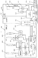
図1は、本発明の実施の形態1に係るカメラシステム1の構成を示すブロック図である。カメラシステム1は、カメラボディ100とそれに着脱可能な交換レンズ200とから構成される。カメラシステム1は、フォーカスレンズ230を駆動することにより、オートフォーカス制御を行うことができる。また、カメラシステム1は、絞り260を駆動することにより、絞り制御を行うことができる。本実施の形態では、レンズ交換式のカメラシステムにおいて、オートフォーカス制御や絞り制御といった可動部材を駆動する制御から、他の制御への移行をスムーズに行うための構成を説明する。
1-1. Configuration 1-1-1. Overview FIG. 1 is a block diagram showing a configuration of a camera system 1 according to Embodiment 1 of the present invention. The camera system 1 includes a
1−1−2.カメラボディの構成
カメラボディ100は、CCDイメージセンサ110と液晶モニタ120とカメラコントローラ140とボディマウント150と電源160とカードスロット170とを備える。
1-1-2. Configuration of Camera Body The
カメラコントローラ140は、レリーズ釦130等の操作部材からの指示に応じて、CCDイメージセンサ110等の構成要素を制御することでカメラシステム1全体を制御する。カメラコントローラ140は、垂直同期信号をタイミング発生器112に送信する。これと並行して、カメラコントローラ140は、垂直同期信号に基づいて露光同期信号を生成する。カメラコントローラ140は、生成した露光同期信号を、ボディマウント150及びレンズマウント250を介して、レンズコントローラ240に周期的に送信する。カメラコントローラ140は、制御動作や画像処理動作の際に、DRAM141をワークメモリとして使用する。
The
CCDイメージセンサ110は、交換レンズ200を介して入射される被写体像を撮像して画像データを生成する。生成された画像データは、ADコンバーター111でデジタル化される。ADコンバーター111でデジタル化された画像データは、カメラコントローラ140により所定の画像処理が施される。所定の画像処理とは、例えば、ガンマ補正処理、ホワイトバランス補正処理、キズ補正処理、YC変換処理、電子ズーム処理、JPEG圧縮処理である。
The
CCDイメージセンサ110は、タイミング発生器112により制御されるタイミングで動作する。CCDイメージセンサ110の動作としては、静止画像の撮像動作、スルー画像の撮像動作等である。スルー画像は、主に動画像であり、使用者が静止画像の撮像のための構図を決めるために液晶モニタ120に表示される。
The
液晶モニタ120は、カメラコントローラ140で画像処理された表示用画像データが示す画像を表示する。液晶モニタ120は、動画像も静止画像も選択的に表示可能である。
The
カードスロット170は、メモリーカード171を装着可能であり、カメラコントローラ140からの制御に基づいて、メモリーカード171を制御する。メモリーカード171は、カメラコントローラ140の画像処理により生成された画像データを格納可能である。例えば、メモリーカード171はJPEG画像ファイルを格納できる。また、メモリーカード171に格納された画像データ又は画像ファイルは読み出し可能であり、メモリーカード171から読み出された画像データ又は画像ファイルは、カメラコントローラ140により画像処理される。例えば、カメラコントローラ140は、メモリーカード171から取得した画像データ又は画像ファイルを伸張して表示用画像データを生成する。
The
電源160は、カメラシステム1で消費するための電力を供給する。電源160は、例えば、乾電池であってもよいし、充電池であってもよい。また、電源160は、電源コードを介して外部からカメラシステム1に電力を供給してもよい。
The
ボディマウント150は、交換レンズ200のレンズマウント250と機械的及び電気的に接続可能である。ボディマウント150は、レンズマウント250を介して、交換レンズ200との間で、データを送受信可能である。ボディマウント150は、カメラコントローラ140から受信した露光同期信号を、レンズマウント250を介してレンズコントローラ240に送信する。また、カメラコントローラ140から受信したその他の制御信号を、レンズマウント250を介してレンズコントローラ240に送信する。例えば、カメラコントローラ140から受信したフォーカスレンズ230の駆動に関する情報を、レンズマウント250を介してレンズコントローラ240に送信する。また、ボディマウント150は、レンズマウント250を介してレンズコントローラ240から受信した信号をカメラコントローラ140に送信する。例えば、ボディマウント150は、レンズマウント250を介してレンズコントローラ240から受信したフォーカスレンズ230の移動の完了を予告する完了予告信号を、カメラコントローラ140に送信する。また、ボディマウント150は、電源160から受けた電力を、レンズマウント250を介して交換レンズ200全体に供給する。
The
1−1−3.交換レンズの構成
交換レンズ200は、光学系とレンズコントローラ240とレンズマウント250とを備える。光学系はズームレンズ210、OISレンズ220、絞り260、フォーカスレンズ230を含む。
1-1-3. Configuration of Interchangeable Lens The
ズームレンズ210は、光学系で形成される被写体像の倍率を変化させるためのレンズである。ズームレンズ210は、1枚又は複数枚のレンズで構成される。駆動機構211は、使用者が操作可能なズームリング等を含み、使用者による操作をズームレンズ210に伝え、ズームレンズ210を光学系の光軸方向に沿って移動させる。検出器212は、駆動機構211における駆動量を検出する。レンズコントローラ240は、この検出器212における検出結果を取得することにより、光学系におけるズーム倍率を把握することができる。
The
OISレンズ220は、交換レンズ200の光学系で形成される被写体像のぶれを補正するためのレンズである。OISレンズ220は、カメラシステム1のぶれを相殺する方向に移動することにより、CCDイメージセンサ110上の被写体像のぶれを小さくする。OISレンズ220は、1枚又は複数枚のレンズで構成される。アクチュエータ221は、OIS用IC223からの制御を受けて、光学系の光軸に垂直な面内でOISレンズ220を駆動する。アクチュエータ221は、例えば、マグネットと平板コイルとで実現可能である。位置検出センサ222は、光学系の光軸に垂直な面内におけるOISレンズ220の位置を検出するセンサである。位置検出センサ222は、例えば、マグネットとホール素子で実現可能である。OIS用IC223は、位置検出センサ222の検出結果及びジャイロセンサ等のぶれ検出器の検出結果に基づいて、アクチュエータ221を制御する。OIS用IC223は、レンズコントローラ240から、ぶれ検出器の検出結果を得る。また、OIS用IC223は、レンズコントローラ240に対して、光学的像ぶれ補正処理の状態を示す信号を送信する。
The
絞り260は、光学系を通過する光の量を調整するための部材である。絞り260は、例えば、複数の絞り羽根からなり、羽根で構成する開口部を開閉することにより、光量を調整可能である。絞りモータ261は、絞り260の開口部を開閉するための駆動手段である。
The
フォーカスレンズ230は、光学系でCCDイメージセンサ110上に形成される被写体像のフォーカス状態を変化させるためのレンズである。フォーカスレンズ230は、1枚又は複数枚のレンズで構成される。
The
フォーカスモータ233は、レンズコントローラ240の制御に基づいて、フォーカスレンズ230が光学系の光軸に沿って進退するよう駆動する。これにより、光学系でCCDイメージセンサ110上に形成される被写体像のフォーカス状態を変化させることができる。本実施の形態1では、フォーカスモータ233として、ステッピングモータを用いる。但し、本発明は、これに限定されない。要するに所定の時間内に所定量フォーカスレンズ230を移動可能なレンズ駆動装置であればよい。このように、フォーカスモータ233はステッピングモータで構成されるため、レンズコントローラ240は、自らが送信するパルス信号の数をカウンタ243でカウントすることによりフォーカスレンズ230の駆動量を検知することができる。
The
レンズコントローラ240は、カメラコントローラ140からの制御信号に基づいて、OIS用IC223やフォーカスモータ233などの交換レンズ200全体を制御する。例えば、レンズコントローラ240は、カメラコントローラ140からの制御信号に基づいて、フォーカスレンズ230を光軸に沿って所定の駆動方法で進退させるようにフォーカスモータ233を制御する。また、検出器212、OIS用IC223などから信号を受信して、カメラコントローラ140に送信する。レンズコントローラ240は、カメラコントローラ140との送受信の際には、レンズマウント250及びボディマウント150を介して行う。
The
レンズコントローラ240は、制御の際、DRAM241をワークメモリとして使用する。また、フラッシュメモリ242は、レンズコントローラ240の制御の際に使用するプログラムやパラメータを保存する。
The
1−1−4.用語の対応
カメラコントローラ140はボディ制御手段の一例である。ボディマウント150は、送信手段及び受信手段の一例である。フォーカスレンズ230と絞り260とは、それぞれ可動部材の一例である。フォーカスモータ233と絞りモータ261とは、それぞれ駆動手段の一例である。レンズマウント250は、受信手段及び送信手段の一例である。レンズコントローラ240はレンズ制御手段の一例である。カメラコントローラ140及びレンズコントローラ240は予測手段の一例である。
1-1-4. Term Correspondence The
1−2.動作
1−2−1.撮像準備動作
まず、撮像準備のためのカメラシステム1の動作を説明する。図2は、カメラシステム1における撮像準備動作を説明するための信号送受信を示した図である。
1-2. Operation 1-2-1. Imaging Preparation Operation First, the operation of the camera system 1 for imaging preparation will be described. FIG. 2 is a diagram illustrating signal transmission / reception for explaining the imaging preparation operation in the camera system 1.
カメラボディ100に交換レンズ200を装着した状態で、使用者が、カメラボディ100の電源をONすると、電源160は、ボディマウント150及びレンズマウント250を介して、交換レンズ200に電力を供給する(S11)。次に、カメラコントローラ140は、レンズコントローラ240に対して、交換レンズ200の認証情報を要求する(S12)。ここで、交換レンズ200の認証情報には、交換レンズ200が装着されているか否かに関する情報及びアクセサリーが装着されているか否かに関する情報が含まれる。レンズコントローラ240は、カメラコントローラ140からのレンズ認証要求に応答する(S13)。
When the user turns on the power supply of the
次に、カメラコントローラ140は、レンズコントローラ240に対して、初期化動作をするよう要求する(S14)。これを受けて、レンズコントローラ240は、絞りのリセット、OISレンズ220のリセット等の初期化動作を行う。そして、レンズコントローラ240は、カメラコントローラ140に対して、レンズ初期化動作が完了した旨を返信する(S15)。
Next, the
次に、カメラコントローラ140は、レンズコントローラ240に対して、レンズデータを要求する(S16)。レンズデータは、フラッシュメモリ242に格納されている。そこで、レンズコントローラ240は、フラッシュメモリ242からレンズデータを読み出して、カメラコントローラ140に返信する(S17)。ここで、レンズデータは、レンズ名称、Fナンバー、焦点距離等の交換レンズ200特有の特性値を含む。
Next, the
カメラコントローラ140が、カメラボディ100に装着されている交換レンズ200のレンズデータを把握すると、撮像可能な状態になる。この状態では、カメラコントローラ140は、レンズコントローラ240に対して、交換レンズ200の状態を示すレンズ状態データを定期的に要求する(S18)。レンズ状態データは、例えば、ズームレンズ210によるズーム倍率情報、フォーカスレンズ230の位置情報、絞り値情報などが含まれる。この要求に応えて、レンズコントローラ240は、カメラコントローラ140に対して、要求されたレンズ状態データを返信する(S19)。
When the
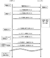
1−2−2.オートフォーカス制御と絞り制御
以上のようにして撮像準備が完了したカメラシステム1におけるオートフォーカス制御と絞り制御について図3〜図5を用いて説明する。本実施形態では、まずオートフォーカス制御が実行され、それに続いて絞り制御が行われるとする。
1-2-2. Autofocus Control and Aperture Control Autofocus control and aperture control in the camera system 1 that has been prepared for imaging as described above will be described with reference to FIGS. In the present embodiment, it is assumed that autofocus control is first performed and then aperture control is performed.
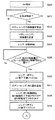
1−2−2−1.オートフォーカス制御
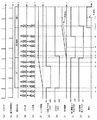
図3のフロー及び図5を参照しながら、カメラシステム1のオートフォーカス制御について説明する。なお、カメラシステム1は、コントラスト方式(いわゆる山登り方式)のオートフォーカス制御を採用している。コントラスト方式のオートフォーカス制御において、カメラボディ100がフォーカスレンズ230の合焦位置を検出後、フォーカスレンズ230を合焦位置に移動する場合について説明する。なお、レンズ交換式のカメラシステムにおいてコントラスト方式のオートフォーカス制御を行う際に、フォーカスレンズの合焦位置を検出する方法は一般に知られているため(例えば、特開2007−322922号公報参照)、ここでの説明を省略する。
1-2-2-1. Auto Focus Control The auto focus control of the camera system 1 will be described with reference to the flow of FIG. 3 and FIG. The camera system 1 employs a contrast method (so-called hill-climbing method) autofocus control. A case where the
図3のフローチャートにおいて、使用者によりオートフォーカス操作がなされると(S20)、カメラシステム1は、フォーカスレンズ230を駆動して合焦点の検出を開始する(S21)。
In the flowchart of FIG. 3, when the user performs an autofocus operation (S20), the camera system 1 drives the
合焦点が検出されると、カメラコントローラ140は、レンズコントローラ240からフォーカスレンズ230の現在の位置情報を取得し、フォーカスレンズ230を移動させるべき移動量を算出する(S22)。移動量を算出すると、カメラコントローラ140は、ボディマウント150とレンズマウント250とを介して、レンズコントローラ240に、フォーカスレンズ230の移動量に関するコマンドを送信する(S23、時刻t1)。なお、必ずしもカメラコントローラ140が移動量をレンズコントローラ240に送信する構成である必要はなく、例えば、フォーカスレンズ230を移動すべき光軸上の位置情報をレンズコントローラ240に送信するような構成であってもよい。
When the in-focus point is detected, the
移動量に関するコマンドを受信すると、レンズコントローラ240は、取得したコマンドに基づいて、フォーカスレンズ230を移動させるようにフォーカスモータ233を制御する(S24、時刻t2)。なお、この制御は、移動量に関するコマンドが送信された際の露光同期信号の次に送信される露光同期信号に同期して行われる。これにより、コマンド取得時点から、フォーカスモータ233の制御への移行がスムーズに行われる。また、レンズコントローラ240は、フォーカスレンズ230の移動の開始と同時に、オートフォーカス駆動完了予測フラグ(以下「AF完了予測フラグ」という。)及びオートフォーカス駆動完了フラグ(以下「AF完了フラグ」という。)を立ち下げる(OFFに設定する)(図5の時刻t2)。なお、必ずしもレンズコントローラ240がフォーカスレンズ230の移動の開始と同時に、AF完了予測フラグ及びAF完了フラグを立ち下げる構成である必要はなく、例えば、コマンド取得と同時に、AF完了予測フラグ及びAF完了フラグを立ち下げる構成であってもよい。
When receiving the command related to the movement amount, the
ここで、AF完了予測フラグとは、オートフォーカス動作が現時点から所定時間内に完了するであろうことを予告するフラグである。ここで、所定時間は、CCDイメージセンサ110が1フレームの画像を撮像するために要する期間(1フレーム期間)と同等の期間に設定する。1フレーム期間は例えばCCDイメージセンサ110の垂直転送期間に相当する。AF完了フラグは、実際にオートフォーカス動作が完了していることを示すフラグである。
Here, the AF completion prediction flag is a flag for notifying that the autofocus operation will be completed within a predetermined time from the present time. Here, the predetermined time is set to a period equivalent to a period (one frame period) required for the
フォーカスレンズ230の移動開始後もカメラコントローラ140とレンズコントローラ240とは、フォーカスレンズ230の駆動などに関するコマンドのやり取りを行う。このコマンドのやり取りは、カメラコントローラ140がレンズコントローラ240に送信する露光同期信号に同期したタイミングで行われる。例えば、交換レンズ200は、カメラボディ100に対して、フォーカスレンズ230の現在位置や、ズームレンズ210の現在位置や、絞り260の絞り状態、各種フラグの状態に関する情報を含むコマンドなどを送信する。
Even after the
また、カメラボディ100は、交換レンズ200対して、フォーカスレンズ230の目標位置に関する情報を含むコマンドや、フォーカスレンズ230の駆動速度に関する情報を含むコマンドなどを送信する。なお、レンズコントローラ240は、フォーカスレンズ230の移動を開始した後、フォーカスモータ233に対して送信したパルス信号の数をカウンタ243でカウントする。これにより、フォーカスレンズ230の現在位置や駆動速度などの駆動状態を検知することができる。
In addition, the
フォーカスレンズ230の移動が開始すると、レンズコントローラ240は、フォーカスレンズ230の移動が、現時点から所定時間内に完了するか否かを判断(予測)する(S25)。すなわち、現時点での残りの移動量が所定時間内に移動可能な量か否かを判断する(S25)。ここで、所定時間は1フレーム期間に設定する。要するに、レンズコントローラ240は、フォーカスレンズ230の動作が次の露光同期信号の周期において完了するか否かを判断する。なお、所定時間内にフォーカスレンズ230の移動が完了するか否かは、フォーカスレンズ230の駆動速度及びカウンタ243のカウント状況を把握することにより判断できる。
When the movement of the
フォーカスレンズ230の移動が所定時間内に終了するであろうと判断(予測)すると、レンズコントローラ240は、オートフォーカス動作が所定時間内に完了することを予告するAF完了予測フラグを立ち上げる(S26、図5の時刻t3)。カメラコントローラ140はレンズコントローラ240からAF完了予測フラグを受信し、AF完了予測フラグに基づき、所定時間内にオートフォーカス動作が完了するであろうことを検知できる。なお、この判断時点では、フォーカスレンズ230の移動の完了を予測するだけであるため、実際のフォーカスレンズ230の移動は完了していない。
If it is determined (predicted) that the movement of the
本実施の形態において、フォーカスモータ233はステッピングモータで構成されているため、レンズコントローラ240は、フォーカスレンズ230の移動が現時点から所定時間内に完了するか否かを判断することができる。しかし、フォーカスモータとして、現時点から所定時間内にフォーカスレンズの駆動が完了するか否かを判断できないモータ(例えば、DCモータ)を備えた交換レンズを、本実施の形態のカメラボディ100に装着する場合も考えられる。このような構成の場合、AFが完全に完了する前には、レンズコントローラ240はAF完了予測フラグを立ち上げない。
In the present embodiment, since the
レンズコントローラ240からAF完了予測フラグを受信すると、カメラコントローラ140は、ボディマウント150とレンズマウント250とを介して、レンズコントローラ240に対して、オートフォーカス制御に続いて実行する絞り制御における目標絞り値に関する情報を含むコマンドを送信する(S27、図5の時刻t4)。
When the AF completion prediction flag is received from the
レンズコントローラ240は、目標絞り値に関する情報を含むコマンドを受信すると、次の同期駆動タイミングで、絞り260の駆動を開始するよう絞りモータ261を制御する(S28、図5の時刻t5)。
When the
レンズコントローラ240は、絞り260の駆動開始と同時に、絞り駆動完了予測フラグと絞り駆動完了フラグを立ち下げる(OFFに設定する)。ここで、絞り駆動完了予測フラグとは、絞り駆動が現時点から所定時間内に完了するであろうことを予告するフラグである。ここで、所定時間とは、CCDイメージセンサ110が1フレームの画像を撮像するために要する期間(1フレーム期間)と同等の期間であり、例えばCCDイメージセンサ110の垂直転送期間に相当する。絞り駆動完了フラグは、実際に絞り駆動が完了していることを示すフラグである。本実施形態では、絞り駆動が行われる度に絞り駆動完了予測フラグと絞り駆動完了フラグを立ち下げる(OFFに設定する)。これにより、絞り駆動の終了前にそれぞれのフラグは常に立ち下がっている(OFFに設定される)こととなる。なお、必ずしもレンズコントローラ240が絞り260の駆動開始と同時に、絞り駆動完了予測フラグ及び絞り駆動完了フラグを立ち下げる構成である必要はなく、例えば、コマンド取得と同時に、絞り駆動完了予測フラグ及び絞り駆動完了フラグを立ち下げる構成であってもよい。
The
絞りモータ261の制御開始後の最初のコマンド送信タイミングにおいて、レンズコントローラ240は、フォーカスレンズ230の移動が完了したことを示すAF完了フラグを立ち上げる(ONに設定する)(S29,図5の時刻t6)。カメラコントローラ140は、レンズマウント250とボディマウント150を介してAF完了フラグを受信し、AF完了フラグを参照することで、フォーカスレンズ230の移動が完了したことを検知することができる。
At the first command transmission timing after starting the control of the
なお、本実施の形態にかかるカメラボディ100に、フォーカスモータとして、現時点から所定時間内にフォーカスレンズの駆動が完了するか否かを判断できないモータ(例えば、DCモータ)を備えた交換レンズを装着した場合は、時刻t6において、AF完了予測フラグとAF完了フラグを同時に立ち上げる(ONに設定する)。この制御により、カメラボディ100は、オートフォーカス動作の完了を事前に予測可能な交換レンズと、オートフォーカス動作の完了を事前に予測不可能な交換レンズとの両方に対応することができる。
Note that an interchangeable lens having a motor (for example, a DC motor) that cannot determine whether or not driving of the focus lens is completed within a predetermined time from the current time is attached to the
このように、本実施の形態においては、オートフォーカス動作が所定時間内に完了することを予測して検出する。そして、検出したときにAF完了予測フラグを立ち上げる。これにより、交換レンズ200は、カメラボディ100に対して現時点から所定時間内にオートフォーカス動作が完了することを通知することができる。その結果、カメラボディ100は、オートフォーカス動作が完了する前に他の制御を指示することができる。
Thus, in the present embodiment, it is detected and predicted that the autofocus operation is completed within a predetermined time. When detected, an AF completion prediction flag is raised. Thereby, the
そして、本実施の形態において、カメラボディ100は、AF完了予測フラグを取得した後の次のコマンド送信タイミングにおいて、目標絞り値に関する情報を含むコマンドを交換レンズ200に対して通知する。これにより、交換レンズ200は、オートフォーカス動作の完了後すぐに絞り260の駆動動作に移行することができる。その結果、本実施の形態にかかるカメラシステムは、オートフォーカス制御から次の制御への移行をスムーズに行うことができる。
In this embodiment, the
例えば、本実施形態のようなAF完了予測フラグを設けなかった場合、カメラコントローラ140は、実際にオートフォーカス動作の完了を検知するまで次の制御に移行することができない。よって、カメラコントローラ140は、実際にオートフォーカス動作の完了を検知した時刻t6の後、すなわち時刻t7において、絞り制御における目標絞り値に関する情報を含むコマンドをレンズコントローラ240に対して送信しなければならない。その場合、レンズコントローラ240は、絞り制御における目標絞り値に関する情報を含むコマンドを受信した時刻t7を含む露光同期周期(制御周期)の次の周期において、すなわち時刻t8において、絞りモータ261の制御を開始する。よって、AF完了予測フラグを設けた場合に比して、(t8−t5)だけ、絞り駆動の開始が遅れてしまう。本実施の形態のようにAF完了予測フラグを設け、AF完了予測フラグを参照してオートフォーカス動作の完了を予測することで、フォーカスレンズ230の移動が実際に完了する前に次の制御を開始でき、カメラコントローラ140によるカメラシステム1の制御の移行が早い段階で可能となる。
For example, when the AF completion prediction flag is not provided as in the present embodiment, the
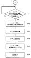
1−2−2−2.絞り制御
上記のオートフォーカス動作の完了後に続けて行われる絞り制御について図4のフローチャート及び図5を参照しながら説明する。
1-2-2-2. Aperture Control A diaphragm control performed after the completion of the autofocus operation will be described with reference to the flowchart of FIG. 4 and FIG.
図4において、レンズコントローラ240は、AF完了フラグの立ち上げを検知すると、目標絞り値への絞り260の駆動が所定期間内に完了するか否かを判断する(S31)。ここで、所定時間は1フレーム期間と同等の期間である。
In FIG. 4, when detecting the rise of the AF completion flag, the
絞り260の駆動が所定時間内に完了するであろうと判断すると、レンズコントローラ240は、絞り駆動完了予測フラグを立ち上げる(ONに設定する)(S33、時刻t9)。これにより、カメラコントローラ140は、絞り駆動完了予測フラグを参照することで絞り駆動が所定期間内に完了するであろうことを検知することができる。
If it is determined that the driving of the
絞り駆動完了予測フラグの立ち上がり後に、カメラコントローラ140は、CCDイメージセンサ110による露光動作の準備を行う(S33)。露光動作の準備が完了すると、カメラコントローラ140は、次の動作タイミングにおいて、CCDイメージセンサ110に対して露光動作を開始させる(S34、時刻t10)。
After the diaphragm drive completion prediction flag rises, the
その後、レンズコントローラ240は、次のコマンド送信タイミングにおいて、絞り駆動完了フラグを立ち上げる(ONに設定する)(S35、時刻t11)。これにより、カメラコントローラ140は、レンズマウント250とボディマウント150とを介して、絞り駆動が完了したことを検知することができる。
Thereafter, the
その後、カメラコントローラ140は、CCDイメージセンサ110に対して継続して露光動作を行う(S36)。
Thereafter, the
このように、本実施の形態においては、絞り駆動が所定時間内に完了することを予測し、絞り駆動完了予測フラグを設定する。交換レンズ200は、絞り駆動完了予測フラグによって、現時点から所定時間内に絞り駆動が完了することをカメラボディ100に通知することができる。その結果、カメラボディ100は、実際に絞り駆動が完了する前に、他の制御の準備を開始することができ、他の制御への移行をスムーズに行える。
Thus, in the present embodiment, it is predicted that the aperture driving will be completed within a predetermined time, and the aperture drive completion prediction flag is set. The
例えば、カメラボディ100は、絞り駆動が完了するであろうと予測される場合、絞り駆動の実際の完了を待たずに、CCDイメージセンサ110に対して露光動作の準備を開始できる。これにより、カメラボディ100は、実際の絞り駆動の完了後すぐに、CCDイメージセンサ110による露光動作に移行することができ、その結果、絞り駆動制御から次の制御への移行をスムーズに行うことができる。
For example, when it is predicted that the aperture drive will be completed, the
例えば、絞り駆動完了予測フラグを設けなかった場合、カメラコントローラ140は、実際の絞り駆動の完了を検知した後でなければ次の制御に移行することができない。従って、図5の例の場合、カメラコントローラ140は、絞り260の駆動が実際に完了したことを検知できる時刻t11以後において露光動作の準備を開始し、露光動作の開始タイミングも時刻t11以後のタイミング(例えば時刻t12)となる。これに対して、絞り駆動完了予測フラグを設けた場合は、前述のとおり時刻t9の後に露光動作の準備を開始でき、早期(時刻t10)に露光動作を開始できる。よって、絞り駆動完了予測フラグを設けなかった場合、絞り駆動完了予測フラグを設けた場合に比して、(t12−t10)だけ露光動作の開始が遅れてしまう。このように、絞り駆動完了予測フラグを設け、これを参照して絞り駆動の完了を予測することで、絞り駆動が実際に完了する前に次の制御を開始でき、カメラコントローラ140によるカメラシステム1の制御の移行が早い段階で可能となる。
For example, when the aperture drive completion prediction flag is not provided, the
本実施形態では、AF完了予測フラグと絞り駆動完了予測フラグのような、光学部材の駆動の完了の予測結果を示すフラグ(完了予測フラグ)とともに、AF完了フラグと絞り駆動完了フラグのような、光学部材の駆動が実際に完了したことを示すフラグ(完了フラグ)を設定している。このような完了フラグにより光学部材の状態を正確に把握できる。このため、完了フラグは、カメラボディ100と交換レンズ200間の同期制御から非同期制御への切り替えや、カメラボディ100と交換レンズ200間の非同期処理を行う際に有用である。例えば、カメラボディ100と交換レンズ200間の同期制御から非同期制御に切り替える際に、完了フラグを参照することにより光学部材の静止状態を正確に把握でき、静止を確認後、同期制御から非同期制御に切り替えることが可能となる。
In the present embodiment, together with a flag (completion prediction flag) indicating a prediction result of the completion of driving of the optical member, such as an AF completion prediction flag and an aperture drive completion prediction flag, an AF completion flag and an aperture drive completion flag, A flag (completion flag) indicating that the driving of the optical member is actually completed is set. Such a completion flag makes it possible to accurately grasp the state of the optical member. Therefore, the completion flag is useful when switching from synchronous control to asynchronous control between the
2.他の実施の形態
実施の形態1では、交換レンズ200からカメラボディ100に対して、フォーカスレンズ230や絞り260の駆動が完了することを通知するためにAF完了予測フラグや絞り駆動完了予測フラグを用いたが、必ずしもこのような情報に限定されるものではない。すなわち、フォーカスレンズ230の駆動が完了することを交換レンズ200がカメラボディ100に通知できれば、どのような種類の情報であってもよい。例えば、フォーカスレンズ230や絞り260の駆動が完了することを通知する情報として、駆動完了までに要する経過時間を示す情報(秒)や、駆動完了までに要するフレームの数を示す情報や、予測した駆動完了のタイミングを示す情報を用いてもよい。
2. Other Embodiments In the first embodiment, an AF completion prediction flag and an aperture drive completion prediction flag are set to notify the
実施の形態1では、交換レンズ200において予測フラグを設定したが、カメラボディ100において予測フラグを設定してもよい。この場合、カメラコントローラ140は、以下のように動作すればよい。カメラコントローラ140は、撮像準備動作において、レンズコントローラ240から、レンズデータに含まれるフォーカスレンズ230及び絞り260それぞれに対する駆動速度に関する情報を取得する。カメラコントローラ140は、オートフォーカス制御及び絞り制御を行う前に、レンズコントローラ240から、現時点のフォーカスレンズ230の位置及び絞り260の開度に関する情報を取得する。そして、カメラコントローラ140は、撮像準備動作において取得したフォーカスレンズ230の駆動速度と、現時点のフォーカスレンズ230の位置とに基づき、フォーカスレンズ230の移動が、現時点から所定時間内に完了するか否かを判断(予測)し、AF完了予測フラグを設定する。同様に、カメラコントローラ140は、撮像準備動作において取得した絞り260の駆動速度と、現時点の開度とに基づき、絞り駆動完了フラグを設定する。
In Embodiment 1, the prediction flag is set in the
実施の形態1では、AF完了予測フラグ及び絞り駆動完了予測フラグの設定において、駆動の完了の予測に用いた所定時間を1フレーム期間としたが、これに限られない。所定時間は、CCDイメージセンサ110がnフレーム(n=2,3,4,…)の画像を撮像するために要する期間としてもよい。また、所定時間は、フレーム単位で示しても良いし、時間(例えば、秒)単位で表しても良い。
In the first embodiment, in the setting of the AF completion prediction flag and the aperture driving completion prediction flag, the predetermined time used for the prediction of the completion of driving is set as one frame period. The predetermined time may be a period required for the
実施の形態1では、オートフォーカス制御に続けて絞り制御を行う構成としたが、必ずしもこのような構成である必要はない。オートフォーカス制御に続けて、再びオートフォーカス制御を行ってもよいし、露光動作を行ってもよい。 In the first embodiment, the aperture control is performed after the autofocus control. However, such a configuration is not necessarily required. Following the autofocus control, the autofocus control may be performed again or the exposure operation may be performed.
実施の形態1では、駆動の完了を予測する対象として、フォーカスレンズ230と絞り260を例示したが、必ずしもこのような構成である必要はない。駆動可能な任意の可動部材に対して実施の形態1の思想は適用できる。
In the first embodiment, the
実施の形態1では、可動部材の駆動完了後に、AF完了フラグや絞り駆動完了フラグをONに設定する構成としたが、必ずしもこのような構成を取る必要はない。AF完了予測フラグや絞り駆動完了予測フラグをONに設定すれば、AF完了フラグや絞り駆動完了フラグは必ずしもONに設定しなくてもよい。 In the first embodiment, the AF completion flag and the aperture drive completion flag are set to ON after the driving of the movable member is completed. However, such a configuration is not necessarily required. If the AF completion prediction flag and the aperture drive completion prediction flag are set to ON, the AF completion flag and the aperture drive completion flag do not necessarily have to be set to ON.
実施の形態1では、ズームレンズ210及びOISレンズ220を有する構成を例示したが、これらは必須の要素ではない。すなわち、ズーム機能を有することのない単焦点レンズを装着したカメラシステムにも実施の形態1の思想は適用可能である。また、手振れ補正機能を有しない交換レンズを装着したカメラシステムにも実施の形態1の思想は適用可能である。
In Embodiment 1, although the structure which has the
実施の形態1では、可動ミラーを備えないカメラボディを例示したが、カメラボディの構成はこれには限定されない。例えば、カメラボディ内に可動ミラーを備えてもよいし、被写体像を分けるためのプリズムを備えてもよい。また、カメラボディ内ではなく、アダプター内に可動ミラーを備える構成でもよい。 In the first embodiment, the camera body that does not include the movable mirror is illustrated, but the configuration of the camera body is not limited to this. For example, a movable mirror may be provided in the camera body, or a prism for separating the subject image may be provided. Moreover, the structure provided with a movable mirror not in a camera body but in an adapter may be sufficient.
実施の形態1では、撮像素子として、CCDイメージセンサ110を例示したが、撮像素子はこれに限定されない。例えば、撮像素子は、CMOSイメージセンサやNMOSイメージセンサで構成してもよい。
In the first embodiment, the
以上、特定の実施形態について説明されてきたが、当業者にとっては他の多くの変形例、修正、他の利用が明らかである。それゆえ、本発明は、ここでの特定の開示に限定されず、添付の請求の範囲によってのみ限定され得る。なお、本出願は日本国特許出願、特願2008−128010号(2008年5月15日提出)に関連し、それらの内容は参照することにより本文中に組み入れられる。 While specific embodiments have been described above, many other variations, modifications, and other uses will be apparent to those skilled in the art. Accordingly, the invention is not limited to the specific disclosure herein, but can be limited only by the scope of the appended claims. This application relates to a Japanese patent application, Japanese Patent Application No. 2008-128010 (submitted on May 15, 2008), the contents of which are incorporated herein by reference.
本発明は、レンズ交換式のカメラシステムに適用できる。具体的には、デジタルスチルカメラやムービーなどに適用可能である。 The present invention can be applied to an interchangeable lens camera system. Specifically, it can be applied to a digital still camera or a movie.
1 カメラシステム
100 カメラボディ
110 CCDイメージセンサ
112 タイミング発生器
130 レリーズ釦
140 カメラコントローラ
200 交換レンズ
230 フォーカスレンズ
233 フォーカスモータ
240 レンズコントローラ
260 絞り
1
Claims (9)
前記カメラボディは、
同期信号とコマンドを生成するボディ制御手段と、
前記生成した同期信号とコマンドを前記交換レンズに送信する送信手段とを備え、
前記交換レンズは、
可動部材と、
前記可動部材を駆動する駆動手段と、
前記カメラボディから、同期信号とコマンドを受信する受信手段と、
前記受信した同期信号に基づいて、前記受信したコマンドに従い前記駆動手段を制御するレンズ制御手段と、
前記受信したコマンドに従い前記駆動手段が前記可動部材を駆動中に、前記受信したコマンドに応じた前記交換レンズの駆動手段の動作が所定期間内に完了するか否かを予測する予測手段と、
前記予測手段による予測結果を前記カメラボディに送信する送信手段と、を備えた、
カメラシステム。 A camera system having an interchangeable lens and a camera body,
The camera body is
Body control means for generating a synchronization signal and a command;
Transmitting means for transmitting the generated synchronization signal and command to the interchangeable lens,
The interchangeable lens is
A movable member;
Drive means for driving the movable member;
Receiving means for receiving a synchronization signal and a command from the camera body;
Lens control means for controlling the driving means in accordance with the received command based on the received synchronization signal ;
Predicting means for predicting whether the operation of the driving means of the interchangeable lens according to the received command is completed within a predetermined period while the driving means is driving the movable member according to the received command ;
Transmission means for transmitting the prediction result by the prediction means to the camera body,
Camera system.
請求項1に記載のカメラシステム。 The prediction result is flag information indicating whether or not the operation of the driving unit of the interchangeable lens according to the received command is completed within a predetermined period.
The camera system according to claim 1 .
可動部材と、
前記可動部材を駆動する駆動手段と、
前記カメラボディから同期信号とコマンドを受信する受信手段と、
前記受信した同期信号に基づいて、前記受信したコマンドに従い前記駆動手段を制御するレンズ制御手段と、
前記受信したコマンドに従い前記駆動手段が前記可動部材を駆動中に、前記受信したコマンドに応じた駆動手段の動作が所定期間内に完了するか否かを予測する予測手段と、
前記予測した結果を前記カメラボディに送信する送信手段と、
を備えた交換レンズ。 An interchangeable lens that can be attached to the camera body,
A movable member;
Drive means for driving the movable member;
Receiving means for receiving a synchronization signal and a command from the camera body;
Lens control means for controlling the driving means in accordance with the received command based on the received synchronization signal;
Predicting means for predicting whether the operation of the driving means according to the received command is completed within a predetermined period while the driving means is driving the movable member according to the received command;
Transmitting means for transmitting the predicted result to the camera body;
Interchangeable lens with
前記カメラボディは、
同期信号とコマンドを生成するボディ制御手段と、
前記生成した同期信号とコマンドを前記交換レンズに送信する送信手段とを備え、
前記交換レンズは、
可動部材と、
前記可動部材を駆動する駆動手段と、
前記カメラボディから、同期信号とコマンドを受信する受信手段と、
前記受信した同期信号に基づいて、前記受信したコマンドに従い前記駆動手段を制御するレンズ制御手段と、
前記受信したコマンドに従い前記駆動手段が前記可動部材を駆動中に、前記受信したコマンドに応じた前記駆動手段の動作が所定期間内に完了するか否かを予測する予測手段と、を備え、
前記レンズ制御手段は、前記予測手段による予測結果を前記カメラボディに送信し、
前記予測結果は、前記受信したコマンドに応じた駆動手段の動作が完了するまでに要する、同期信号の周期の数を示す情報である、
カメラシステム。 A camera system having an interchangeable lens and a camera body,
The camera body is
Body control means for generating a synchronization signal and a command;
Transmitting means for transmitting the generated synchronization signal and command to the interchangeable lens,
The interchangeable lens is
A movable member;
Drive means for driving the movable member;
Receiving means for receiving a synchronization signal and a command from the camera body;
Lens control means for controlling the driving means in accordance with the received command based on the received synchronization signal;
Predicting means for predicting whether or not the operation of the driving means according to the received command is completed within a predetermined period while the driving means is driving the movable member in accordance with the received command,
The lens control means transmits a prediction result by the prediction means to the camera body,
The prediction result is information indicating the number of cycles of the synchronization signal required until the operation of the driving unit according to the received command is completed.
Camera system.
Priority Applications (1)
| Application Number | Priority Date | Filing Date | Title |
|---|---|---|---|
| JP2010511898A JP5406830B2 (en) | 2008-05-15 | 2009-05-15 | Camera system |
Applications Claiming Priority (4)
| Application Number | Priority Date | Filing Date | Title |
|---|---|---|---|
| JP2008128010 | 2008-05-15 | ||
| JP2008128010 | 2008-05-15 | ||
| JP2010511898A JP5406830B2 (en) | 2008-05-15 | 2009-05-15 | Camera system |
| PCT/JP2009/002162 WO2009139192A1 (en) | 2008-05-15 | 2009-05-15 | Camera system |
Publications (2)
| Publication Number | Publication Date |
|---|---|
| JPWO2009139192A1 JPWO2009139192A1 (en) | 2011-09-15 |
| JP5406830B2 true JP5406830B2 (en) | 2014-02-05 |
Family
ID=41318566
Family Applications (1)
| Application Number | Title | Priority Date | Filing Date |
|---|---|---|---|
| JP2010511898A Active JP5406830B2 (en) | 2008-05-15 | 2009-05-15 | Camera system |
Country Status (5)
| Country | Link |
|---|---|
| US (1) | US8542989B2 (en) |
| EP (1) | EP2280306B1 (en) |
| JP (1) | JP5406830B2 (en) |
| CN (1) | CN102027409B (en) |
| WO (1) | WO2009139192A1 (en) |
Families Citing this family (22)
| Publication number | Priority date | Publication date | Assignee | Title |
|---|---|---|---|---|
| WO2011064850A1 (en) * | 2009-11-25 | 2011-06-03 | キヤノン株式会社 | Image pickup device and interchangeable lens |
| JP5605030B2 (en) * | 2010-07-06 | 2014-10-15 | 株式会社ニコン | Camera body and interchangeable lens |
| JP5165099B2 (en) * | 2010-12-10 | 2013-03-21 | キヤノン株式会社 | Imaging device and lens unit |
| JP5573770B2 (en) | 2011-05-13 | 2014-08-20 | 株式会社ニコン | Interchangeable lens and camera body |
| JP6127975B2 (en) * | 2011-09-12 | 2017-05-17 | 株式会社ニコン | interchangeable lens |
| CN104040404B (en) * | 2012-01-13 | 2016-11-09 | 佳能株式会社 | Lens unit and control method thereof and picture pick-up device and control method thereof |
| JP6141001B2 (en) * | 2012-01-13 | 2017-06-07 | キヤノン株式会社 | Imaging apparatus, lens unit, and control method thereof |
| JP5414831B2 (en) | 2012-04-23 | 2014-02-12 | キヤノン株式会社 | Interchangeable lens device and control method thereof, imaging device and control method thereof, and imaging system |
| EP2658243B1 (en) | 2012-04-26 | 2019-08-14 | Canon Kabushiki Kaisha | Image capture apparatus, lens unit, communication controlling method, and diaphragm controlling method |
| JP6157058B2 (en) * | 2012-04-26 | 2017-07-05 | キヤノン株式会社 | Imaging apparatus and communication control method |
| JP5645875B2 (en) * | 2012-05-14 | 2014-12-24 | キヤノン株式会社 | Imaging device, lens device, and imaging system |
| JP5832373B2 (en) * | 2012-05-16 | 2015-12-16 | キヤノン株式会社 | Interchangeable lens device and camera device |
| JP5917288B2 (en) * | 2012-05-18 | 2016-05-11 | キヤノン株式会社 | Imaging device, lens device, and imaging system |
| JP5984517B2 (en) * | 2012-06-05 | 2016-09-06 | キヤノン株式会社 | IMAGING DEVICE, LENS UNIT, IMAGING DEVICE CONTROL METHOD, LENS UNIT CONTROL METHOD, AND IMAGING SYSTEM |
| JP6153419B2 (en) * | 2013-08-09 | 2017-06-28 | キヤノン株式会社 | Automatic focus adjustment device, lens device, automatic focus adjustment method and program |
| JP5708737B2 (en) * | 2013-09-02 | 2015-04-30 | 株式会社ニコン | Interchangeable lens and camera body |
| JP5965553B2 (en) * | 2013-11-08 | 2016-08-10 | 富士フイルム株式会社 | Camera system, camera body, interchangeable lens, and communication method |
| US10187561B2 (en) * | 2016-03-31 | 2019-01-22 | Canon Kabushiki Kaisha | Accessory apparatus, image-capturing apparatus, control apparatus, lens apparatus, control method, computer program and storage medium storing computer program |
| JP2017181830A (en) * | 2016-03-31 | 2017-10-05 | キヤノン株式会社 | Accessory device, imaging device, and communication control device |
| JP6272382B2 (en) | 2016-03-31 | 2018-01-31 | キヤノン株式会社 | Accessory device, imaging device, and communication control program |
| JP6214709B2 (en) * | 2016-03-31 | 2017-10-18 | キヤノン株式会社 | Accessory device, imaging device, and communication control program |
| JP6911304B2 (en) * | 2016-09-07 | 2021-07-28 | ソニーグループ株式会社 | Imaging control device and imaging control method |
Citations (3)
| Publication number | Priority date | Publication date | Assignee | Title |
|---|---|---|---|---|
| JPH0850229A (en) * | 1994-05-31 | 1996-02-20 | Nikon Corp | Image pickup device system, interchangeable lens and image pickup device |
| JPH0875991A (en) * | 1994-09-07 | 1996-03-22 | Nikon Corp | Autofocusing camera |
| JP2008276131A (en) * | 2007-05-07 | 2008-11-13 | Matsushita Electric Ind Co Ltd | Camera system |
Family Cites Families (26)
| Publication number | Priority date | Publication date | Assignee | Title |
|---|---|---|---|---|
| JPS61270882A (en) | 1985-05-25 | 1986-12-01 | Nippon Kogaku Kk <Nikon> | Laser processing equipment |
| US5463442A (en) * | 1988-08-31 | 1995-10-31 | Canon Kabushiki Kaisha | Interchangeable lens unit for use in camera system |
| JP2714039B2 (en) * | 1988-09-26 | 1998-02-16 | キヤノン株式会社 | Camera device |
| JP2790249B2 (en) * | 1988-11-17 | 1998-08-27 | オリンパス光学工業株式会社 | Camera system |
| EP0424678B1 (en) * | 1989-09-27 | 1996-09-04 | Canon Kabushiki Kaisha | Camera system controlling interchangeable lenses |
| GB2250829B (en) * | 1990-11-29 | 1994-08-17 | Asahi Optical Co Ltd | Automatic focusing device |
| JPH06183109A (en) | 1992-12-18 | 1994-07-05 | Fuji Xerox Co Ltd | Printer system |
| US6128443A (en) * | 1996-12-11 | 2000-10-03 | Canon Kabushiki Kaisha | Camera and interchangeable lens |
| JP3992286B2 (en) * | 2005-01-28 | 2007-10-17 | キヤノン株式会社 | Camera system and interchangeable lens |
| JP4137106B2 (en) * | 2005-09-09 | 2008-08-20 | キヤノン株式会社 | Imaging device, lens device, and imaging system |
| JP2007310009A (en) * | 2006-05-16 | 2007-11-29 | Olympus Imaging Corp | Digital camera and camera system |
| JP4963569B2 (en) | 2006-06-02 | 2012-06-27 | オリンパスイメージング株式会社 | Imaging system and lens unit |
| JP2008015274A (en) * | 2006-07-06 | 2008-01-24 | Olympus Imaging Corp | Digital camera |
| JP5037886B2 (en) * | 2006-09-21 | 2012-10-03 | キヤノン株式会社 | Imaging system, imaging apparatus, and lens apparatus |
| JP4963406B2 (en) | 2006-11-16 | 2012-06-27 | 一般財団法人電力中央研究所 | Gas turbine combustor and operation method thereof |
| US7853138B2 (en) * | 2007-02-19 | 2010-12-14 | Canon Kabushiki Kaisha | Camera and photographic lens and diaphragm for starting a defocus detection without waiting for completion of an aperture opening operation |
| US7773872B2 (en) * | 2007-02-19 | 2010-08-10 | Canon Kabushiki Kaisha | Camera having a function of predicting a future image plane position from a change in a plurality of past image plane positions and of time detection, a photographic lens to be mounted on the same, and a camera system |
| JP2008275890A (en) * | 2007-04-27 | 2008-11-13 | Olympus Imaging Corp | Digital camera with interchangeable lens |
| US20110141340A1 (en) * | 2007-05-07 | 2011-06-16 | Naoto Yumiki | Interchangeable lens and camera system using the same |
| WO2009016836A1 (en) * | 2007-07-31 | 2009-02-05 | Panasonic Corporation | Camera system and camera body |
| JP5157377B2 (en) * | 2007-11-12 | 2013-03-06 | 株式会社ニコン | Focus detection apparatus and imaging apparatus |
| US8208057B2 (en) * | 2008-03-27 | 2012-06-26 | Panasonic Corporation | Imaging system, camera body and interchangeable lens |
| US8493498B2 (en) * | 2008-05-16 | 2013-07-23 | Panasonic Corporation | Image apparatus system, camera body and interchangeable lens |
| JP5335468B2 (en) * | 2009-02-17 | 2013-11-06 | キヤノン株式会社 | Camera system |
| KR101590872B1 (en) * | 2009-11-09 | 2016-02-02 | 삼성전자주식회사 | Camera system and image forming apparatus |
| KR101720192B1 (en) * | 2011-01-19 | 2017-03-27 | 삼성전자주식회사 | Auto focusing apparatus |
-
2009
- 2009-05-15 WO PCT/JP2009/002162 patent/WO2009139192A1/en active Application Filing
- 2009-05-15 EP EP09746399.6A patent/EP2280306B1/en active Active
- 2009-05-15 CN CN200980117275.0A patent/CN102027409B/en active Active
- 2009-05-15 US US12/992,323 patent/US8542989B2/en active Active
- 2009-05-15 JP JP2010511898A patent/JP5406830B2/en active Active
Patent Citations (3)
| Publication number | Priority date | Publication date | Assignee | Title |
|---|---|---|---|---|
| JPH0850229A (en) * | 1994-05-31 | 1996-02-20 | Nikon Corp | Image pickup device system, interchangeable lens and image pickup device |
| JPH0875991A (en) * | 1994-09-07 | 1996-03-22 | Nikon Corp | Autofocusing camera |
| JP2008276131A (en) * | 2007-05-07 | 2008-11-13 | Matsushita Electric Ind Co Ltd | Camera system |
Also Published As
| Publication number | Publication date |
|---|---|
| EP2280306B1 (en) | 2013-10-23 |
| CN102027409B (en) | 2014-10-29 |
| EP2280306A4 (en) | 2012-07-04 |
| US20110064397A1 (en) | 2011-03-17 |
| CN102027409A (en) | 2011-04-20 |
| WO2009139192A1 (en) | 2009-11-19 |
| EP2280306A1 (en) | 2011-02-02 |
| JPWO2009139192A1 (en) | 2011-09-15 |
| US8542989B2 (en) | 2013-09-24 |
Similar Documents
| Publication | Publication Date | Title |
|---|---|---|
| JP5406830B2 (en) | Camera system | |
| US8724012B2 (en) | Camera body and camera system using driving method information indicating capability of controlling focus lens | |
| JP5903608B2 (en) | Camera system | |
| JP5535080B2 (en) | Camera system | |
| JP5604293B2 (en) | Camera system | |
| JP4594450B2 (en) | Interchangeable lens, camera body, camera system | |
| JP5853197B2 (en) | Interchangeable lens, camera body and camera system | |
| WO2009139118A1 (en) | Camera system | |
| JP2017147720A (en) | Imaging device having zoom mechanism and interchangeable lens | |
| EP2290948A1 (en) | Camera system | |
| JP5520214B2 (en) | Camera system | |
| JP2010061162A (en) | Imaging apparatus system and camera system | |
| JP2010107711A (en) | Focal point control device and imaging apparatus | |
| JP2011175128A (en) | Camera system and camera body | |
| JP2010107714A (en) | Camera system | |
| JP2024092437A (en) | Interchangeable lens, imaging device, and program | |
| JP6429485B2 (en) | Imaging apparatus, communication control method, and imaging system |
Legal Events
| Date | Code | Title | Description |
|---|---|---|---|
| A521 | Request for written amendment filed |
Free format text: JAPANESE INTERMEDIATE CODE: A523 Effective date: 20120502 |
|
| A621 | Written request for application examination |
Free format text: JAPANESE INTERMEDIATE CODE: A621 Effective date: 20120502 |
|
| A131 | Notification of reasons for refusal |
Free format text: JAPANESE INTERMEDIATE CODE: A131 Effective date: 20130618 |
|
| A521 | Request for written amendment filed |
Free format text: JAPANESE INTERMEDIATE CODE: A523 Effective date: 20130729 |
|
| TRDD | Decision of grant or rejection written | ||
| A01 | Written decision to grant a patent or to grant a registration (utility model) |
Free format text: JAPANESE INTERMEDIATE CODE: A01 Effective date: 20131008 |
|
| A61 | First payment of annual fees (during grant procedure) |
Free format text: JAPANESE INTERMEDIATE CODE: A61 Effective date: 20131101 |
|
| R150 | Certificate of patent or registration of utility model |
Ref document number: 5406830 Country of ref document: JP Free format text: JAPANESE INTERMEDIATE CODE: R150 |