JP6153419B2 - Automatic focus adjustment device, lens device, automatic focus adjustment method and program - Google Patents
Automatic focus adjustment device, lens device, automatic focus adjustment method and program Download PDFInfo
- Publication number
- JP6153419B2 JP6153419B2 JP2013167167A JP2013167167A JP6153419B2 JP 6153419 B2 JP6153419 B2 JP 6153419B2 JP 2013167167 A JP2013167167 A JP 2013167167A JP 2013167167 A JP2013167167 A JP 2013167167A JP 6153419 B2 JP6153419 B2 JP 6153419B2
- Authority
- JP
- Japan
- Prior art keywords
- drive
- focus
- lens
- operation member
- control
- Prior art date
- Legal status (The legal status is an assumption and is not a legal conclusion. Google has not performed a legal analysis and makes no representation as to the accuracy of the status listed.)
- Active
Links
Images


Classifications
-
- G—PHYSICS
- G03—PHOTOGRAPHY; CINEMATOGRAPHY; ANALOGOUS TECHNIQUES USING WAVES OTHER THAN OPTICAL WAVES; ELECTROGRAPHY; HOLOGRAPHY
- G03B—APPARATUS OR ARRANGEMENTS FOR TAKING PHOTOGRAPHS OR FOR PROJECTING OR VIEWING THEM; APPARATUS OR ARRANGEMENTS EMPLOYING ANALOGOUS TECHNIQUES USING WAVES OTHER THAN OPTICAL WAVES; ACCESSORIES THEREFOR
- G03B13/00—Viewfinders; Focusing aids for cameras; Means for focusing for cameras; Autofocus systems for cameras
- G03B13/32—Means for focusing
- G03B13/34—Power focusing
- G03B13/36—Autofocus systems
-
- G—PHYSICS
- G02—OPTICS
- G02B—OPTICAL ELEMENTS, SYSTEMS OR APPARATUS
- G02B7/00—Mountings, adjusting means, or light-tight connections, for optical elements
- G02B7/28—Systems for automatic generation of focusing signals
-
- G—PHYSICS
- G03—PHOTOGRAPHY; CINEMATOGRAPHY; ANALOGOUS TECHNIQUES USING WAVES OTHER THAN OPTICAL WAVES; ELECTROGRAPHY; HOLOGRAPHY
- G03B—APPARATUS OR ARRANGEMENTS FOR TAKING PHOTOGRAPHS OR FOR PROJECTING OR VIEWING THEM; APPARATUS OR ARRANGEMENTS EMPLOYING ANALOGOUS TECHNIQUES USING WAVES OTHER THAN OPTICAL WAVES; ACCESSORIES THEREFOR
- G03B3/00—Focusing arrangements of general interest for cameras, projectors or printers
- G03B3/10—Power-operated focusing
-
- H—ELECTRICITY
- H04—ELECTRIC COMMUNICATION TECHNIQUE
- H04N—PICTORIAL COMMUNICATION, e.g. TELEVISION
- H04N23/00—Cameras or camera modules comprising electronic image sensors; Control thereof
- H04N23/60—Control of cameras or camera modules
- H04N23/667—Camera operation mode switching, e.g. between still and video, sport and normal or high- and low-resolution modes
-
- H—ELECTRICITY
- H04—ELECTRIC COMMUNICATION TECHNIQUE
- H04N—PICTORIAL COMMUNICATION, e.g. TELEVISION
- H04N23/00—Cameras or camera modules comprising electronic image sensors; Control thereof
- H04N23/60—Control of cameras or camera modules
- H04N23/67—Focus control based on electronic image sensor signals
Landscapes
- Physics & Mathematics (AREA)
- General Physics & Mathematics (AREA)
- Engineering & Computer Science (AREA)
- Multimedia (AREA)
- Signal Processing (AREA)
- Optics & Photonics (AREA)
- Studio Devices (AREA)
- Focusing (AREA)
- Automatic Focus Adjustment (AREA)
Description
本発明は、カメラシステムなどにおける自動焦点調節装置、自動焦点調節方法などに関し、特にレンズの駆動方法の技術に関するものである。 The present invention relates to an automatic focus adjustment device, an automatic focus adjustment method, and the like in a camera system and the like, and more particularly to a technique for driving a lens.
自動焦点調節の制御方式は、大きく分けて2種類ある。1つは、ワンショット(すなわちシングルAF)方式で、静止している被写体の撮影用で、シャッターボタンの半押しなどでオートフォーカス(AF)が作動し始め、合焦後はフォーカスロックするものである。もう1つは、AIサーボ(すなわちコンティニュアスAFなどのAF)方式で、移動している被写体の撮影用で、シャッターを完全にオフしない限り周期的に焦点検出およびレンズ駆動を続ける。 There are roughly two types of control methods for automatic focusing. One is a one-shot (that is, single AF) method for shooting a stationary subject. Autofocus (AF) starts to operate when the shutter button is pressed halfway, and the focus is locked after focusing. is there. The other is an AI servo (ie, AF such as continuous AF) system for photographing a moving subject, and continues focus detection and lens driving periodically unless the shutter is completely turned off.
従来、レンズの距離環(すなわちピントズレを無くするようにレンズを駆動操作するピント操作部材)の駆動は、停止精度を優先すると時間がかかり、駆動時間を優先すると停止精度が落ちるという駆動時間と停止精度間にトレードオフの関係がある。しかしながら、現状、カメラで設定できるのは、距離環駆動量と駆動速度のみである。ワンショットの場合は、撮影者が合焦を確認してからシャッターを押すため、シャッターが押されていない限り、停止精度を優先すべきである。AIサーボの場合は、動体へ追従中に所定時間内に距離環駆動が間に合わないならば、停止精度より駆動時間を優先すべきである。 Conventionally, driving of a lens distance ring (that is, a focus operation member that drives a lens so as to eliminate a focus shift) takes time when priority is given to stop accuracy, and drive time and stop when stop time is given priority and drive accuracy decreases. There is a trade-off between accuracy. However, at present, only the distance ring driving amount and the driving speed can be set by the camera. In the case of one shot, since the photographer confirms the in-focus state and presses the shutter, the stop accuracy should be given priority unless the shutter is pressed. In the case of the AI servo, if the distance ring driving is not in time within a predetermined time while following the moving object, the driving time should be given priority over the stopping accuracy.
こうした技術に関して、特許文献1は次のようなカメラを開示している。すなわち、動体予測制御を行うカメラにおいて、焦点調節レンズ位置が駆動目標位置に達せず、レンズ駆動初期期間内にレンズ駆動が停止しない場合は、レンズ駆動期間延長手段と再動体予測演算手段により所定の延長期間を設定する。そして、レンズ制御手段は、駆動期間延長時は再動体予測演算手段により算出された目標位置で焦点調節レンズの駆動制御を行う。 With regard to such technology, Patent Document 1 discloses the following camera. That is, in a camera that performs moving object prediction control, when the focus adjustment lens position does not reach the drive target position and the lens driving does not stop within the initial lens driving period, the lens driving period extending unit and the moving object prediction calculating unit Set the extension period. The lens control means performs drive control of the focus adjustment lens at the target position calculated by the moving object prediction calculation means when the drive period is extended.
しかし、カメラで設定できるのが距離環駆動量と駆動速度のみでは、カメラはいつ駆動完了するのか分からず、ワンショットモードとAIサーボモードの要求に応えることができない。図9に、従来例のこうした事情を図式化したものを示す。また、上述の特許文献1に開示された従来技術では、次第に単位時間あたりの駒数(コマ速)が落ちて、限界性能も落ちるだけということになりやすい。本発明の目的は、レンズの加減速制御や駆動時間をカメラで制御することを可能にし、ワンショットやAIサーボのモードごとに最適なピント操作部材の駆動制御が実現できる自動焦点調節装置、自動焦点調節方法などを提供することである。 However, if only the distance ring driving amount and the driving speed can be set by the camera, the camera does not know when the driving is completed, and cannot meet the requirements of the one-shot mode and the AI servo mode. FIG. 9 shows a schematic diagram of this situation in the conventional example. In the prior art disclosed in Patent Document 1 described above, the number of frames per unit time (frame speed) gradually decreases, and the limit performance tends to decrease. An object of the present invention is to provide an automatic focus adjustment device capable of controlling lens acceleration / deceleration control and drive time with a camera, and capable of realizing optimum focus operation member drive control for each mode of one-shot and AI servo. It is to provide a focus adjustment method.
上記目的を達成するために、本発明の撮像装置における自動焦点調節装置は、被写体像を撮像素子に形成する撮影光学系と、前記撮影光学系に含まれるレンズを駆動するピント操作部材を含むレンズ駆動ユニットと、前記ピント操作部材の駆動制御態様を制御する第2の制御手段と、を備えるレンズ装置が着脱可能に装着される撮像装置の焦点調節装置であって、被写体像のピントズレを検出する検出手段と、前記検出手段の検出結果から前記ピント操作部材の駆動量を取得し、設定された自動焦点調節の制御方式に応じて前記ピント操作部材の駆動許容時間を取得する第1の制御手段と、を備え、前記第2の制御手段は、前記第1の制御手段からの前記ピント操作部材の駆動量と駆動許容時間に基づき、駆動許容時間を満たすように前記ピント操作部材の駆動制御態様を制御することを特徴とする。また、カメラ本体側からレンズ側へ、レンズを駆動するピント操作部材の駆動量を通信するカメラシステムにおける自動焦点調節方法であって、カメラ本体側で、設定された自動焦点調節の制御方式に応じたピント操作部材の駆動許容時間を取得する工程と、カメラ本体側からレンズ側へ、被写体像のピントズレに応じた前記ピント操作部材の駆動量と、前記ピント操作部材の前記駆動許容時間とを送信する工程と、レンズ側で、前記駆動許容時間を満たすようにピント操作部材の駆動制御態様を切り替える工程と、を有する。 In order to achieve the above object, an automatic focusing apparatus in an imaging apparatus of the present invention includes a photographing optical system that forms a subject image on an imaging element, and a lens that includes a focus operation member that drives a lens included in the photographing optical system. A focus adjustment device for an imaging apparatus to which a lens apparatus including a drive unit and a second control unit that controls a drive control mode of the focus operation member is detachably mounted, and detects a focus shift of a subject image. A first control unit that obtains a drive amount of the focus operation member from a detection result of the detection unit and a detection result of the detection unit, and obtains an allowable drive time of the focus operation member according to a set control method of automatic focus adjustment; When, wherein the second control means, based on the driving amount of the focus operation member and the drive allowable time from the first control means, said pin so as to satisfy the drive allowable time And controlling the drive control mode of the preparative operation member. Also, an auto focus adjustment method in a camera system that communicates the driving amount of a focus operation member that drives a lens from the camera body side to the lens side, and according to the control method of auto focus adjustment set on the camera body side transmission and obtaining a driving time allowed for focusing operating member, from the camera body to the lens side, a driving amount of the focus operation member corresponding to the focus deviation of the object image, and the drive allowable time of the focus operating member And a step of switching the drive control mode of the focus operation member so as to satisfy the allowable drive time on the lens side.
本発明によれば、自動焦点調節の制御方式に応じて、すなわちワンショットやAIサーボのモードごとに好適なピント操作部材の駆動制御が実現できる。 According to the present invention, it is possible to realize suitable focus control member drive control in accordance with the control method of automatic focus adjustment, that is, for each mode of one-shot or AI servo.
本発明では、被写体像を撮像素子に形成するためのレンズを駆動するピント操作部材を含むレンズ駆動ユニットと、被写体像のピントズレを検出する検出手段と、を含む構成において、次の如き制御を行う。すなわち、検出手段の検出結果からピント操作部材の駆動量を取得すると共に、設定された自動焦点調節の制御方式に応じてピント操作部材の駆動許容時間を取得する。そして、これらの駆動量と駆動許容時間に基づき、駆動許容時間を満たすようにピント操作部材すなわちレンズの駆動制御態様を制御する。駆動許容時間を満たすとは、その駆動許容時間の内でピント操作部材すなわちレンズの駆動が行われることである。 In the present invention, the following control is performed in a configuration including a lens driving unit including a focus operation member that drives a lens for forming a subject image on an image sensor and a detection unit that detects a focus shift of the subject image. . In other words, the drive amount of the focus operation member is acquired from the detection result of the detection means, and the allowable drive time of the focus operation member is acquired according to the set automatic focus adjustment control method. Based on these drive amounts and drive allowable time, the focus control member, that is, the lens drive control mode is controlled so as to satisfy the drive allowable time. Satisfying the allowable drive time means that the focus operation member, that is, the lens is driven within the allowable drive time.
以下に、本発明の好ましい実施の形態を、添付の図面に基づいて詳細に説明する。図1〜図8を参照して、本実施形態に係る自動焦点調節装置ないし方法を採用するカメラシステムを説明する。 Hereinafter, preferred embodiments of the present invention will be described in detail with reference to the accompanying drawings. With reference to FIGS. 1-8, the camera system which employ | adopts the automatic focus adjustment apparatus thru | or method which concerns on this embodiment is demonstrated.
図1は、本実施形態におけるカメラシステムの構成図である。1は、第2の制御手段であるレンズMPUで、レンズの制御を行う。MPU1には、メモリが内蔵されておりレンズを制御するためのプログラムが格納されている。2は、ピント操作部材を含むレンズ駆動ユニットで、レンズMPU1の指示でレンズの駆動制御を行う。3は絞り駆動ユニットで、レンズMPU1の指示で絞りの駆動制御を行う。 FIG. 1 is a configuration diagram of a camera system in the present embodiment. Reference numeral 1 denotes a lens MPU which is a second control unit, which controls the lens. The MPU 1 has a built-in memory and stores a program for controlling the lens. Reference numeral 2 denotes a lens driving unit including a focus operation member, which performs lens driving control in response to an instruction from the lens MPU1. Reference numeral 3 denotes an aperture driving unit, which controls aperture driving in response to an instruction from the lens MPU1.
4は、第1の制御手段であるカメラMPUで、カメラ全体の制御を行う。MPU4には、メモリが内蔵されておりカメラを制御するためのプログラムが格納されている。5はミラー駆動ユニットで、カメラのカメラMPU4の指示でメインミラーの駆動を行う。6はデフォーカス量検出ユニットで、ピントのズレ量を検出する。7は撮影ユニットで、カメラMPU1の指示で撮影全体を制御する。レンズを通して被写体の像が撮像素子に形成され、撮影ユニット7は撮像素子からの信号を処理し、この処理信号を用いて、例えば、画像がカメラMPU1の指示で表示パネルに表示される。8は測光ユニットで、明るさを検出する。9はEEPROMで、カメラの制御に必要な各種パラメータが格納されている。
10は記録ユニットで、カメラMPU1の指示で、撮影された画像の記録を行う。11はダイヤル/SWユニットで、操作者がカメラに指示を与える操作部材である。12は表示ユニットで、撮影した画像とその画像情報、カメラの各種情報、カメラの設定情報などを、表示パネル上に表示する。カメラとレンズは、マウントを通して結合され、レンズMPU1とカメラMPU4の間で各種情報が通信可能となっている。
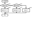
本実施形態のカメラ本体側の駆動制御方法ないし態様を図1のカメラシステム構成図と図2のフローチャートと図3の距離環駆動許容時間の算出テーブルを使用して説明する。S21において、ダイヤル/SWユニット11からAFモードを選択する。S22において、ダイヤル/SWユニット11からコマ速を設定する。S23において、カスタムファンクションのコマ速優先か被写体追随優先を選択する。カメラの操作者がS21〜S23を省略した場合は、カメラの電源投入時に予め決められたAFモード、コマ速、カスタムファンクション設定で動作する。S24において、AIサーボモードかどうかを判定し、AIサーボモードならばS25に進み、AIサーボモードでないならば、すなわちワンショットモードならばS26に進む。以上のように、AIサーボモードの時に、AIサーボモードのコマ速優先か被写体追随優先かの選択に係るカスタムファンクションの設定に応じた駆動許容時間を通信することができる。 A drive control method or mode on the camera body side of the present embodiment will be described using the camera system configuration diagram of FIG. 1, the flowchart of FIG. 2, and the distance ring drive allowable time calculation table of FIG. In S21, the AF mode is selected from the dial / SW unit 11. In S22, the frame speed is set from the dial / SW unit 11. In S23, the custom function frame speed priority or subject tracking priority is selected. When the camera operator omits S21 to S23, the camera operates in the AF mode, the frame speed, and the custom function setting determined in advance when the camera is turned on. In S24, it is determined whether the AI servo mode is selected. If the AI servo mode is selected, the process proceeds to S25. If the AI servo mode is not selected, that is, if the one-shot mode is selected, the process proceeds to S26. As described above, in the AI servo mode, it is possible to communicate the allowable drive time according to the setting of the custom function relating to the selection of the frame speed priority or the subject tracking priority in the AI servo mode.
S25において、図3の距離環駆動許容時間テーブルからAIサーボモード用の短い距離環駆動許容時間を算出する。図3のテーブルには、コマ速、コマ速優先設定、被写体追随優先設定の組合せにおける最適な駆動許容時間が記載され、EEPROM9に格納されている。テーブル記載の駆動許容時間は、シミュレーションや実測等で決定したそれぞれの設定状態における最適値である。S25におけるAIサーボモード用の短い距離環駆動許容時間の別の算出方法としては次の如き方法も可能である。すなわち、シャッター半押し中はAFの測距周期(例えば100msec)、シャッターが全押しされたらシャッターが押されてから露光を開始するまでの時間(例えば55msec)を、距離環駆動許容時間として算出する。また、連写中は次の露光タイミングまでの時間(コマ速で異なる)を、距離環駆動許容時間として算出する。以上のように、自動焦点調節の制御方式がAIサーボモードの時に、AIサーボモードの設定コマ速に応じた駆動許容時間を通信することができる。 In S25, the short distance ring drive allowable time for the AI servo mode is calculated from the distance ring drive allowable time table of FIG. In the table of FIG. 3, the optimum drive allowable time in the combination of the frame speed, the frame speed priority setting, and the subject tracking priority setting is described and stored in the EEPROM 9. The allowable drive time described in the table is an optimum value in each setting state determined by simulation, actual measurement, or the like. As another method of calculating the short distance ring drive allowable time for the AI servo mode in S25, the following method is also possible. That is, the AF distance measurement cycle (for example, 100 msec) while the shutter is half-pressed, and the time from when the shutter is fully pressed until the exposure is started (for example, 55 msec) are calculated as the distance ring drive allowable time. . Further, during continuous shooting, the time until the next exposure timing (which varies depending on the frame speed) is calculated as the distance ring drive allowable time. As described above, when the automatic focus adjustment control method is the AI servo mode, the allowable drive time according to the set frame speed in the AI servo mode can be communicated.
ワンショットの場合は、静止している被写体撮影用なので、停止精度優先のレンズ駆動とするため、駆動許容時間を無制限とする。したがって、S26において、ワンショットモード用の長い距離環駆動許容時間を算出する。つまり、ワンショットモードの時は、AIサーボモードの時より長い駆動許容時間を通信し、AIサーボモードの時は、ワンショットモードの時より短い駆動許容時間を通信する。S27において、カメラMPU4からレンズMPU1へ距離環許容時間を送信する。S28において、カメラMPU4からレンズMPU1へ駆動量を送信する。この駆動量は、ピントズレを検出する検出手段であるデフォーカス量検出ユニット6により検出されたピントのズレ量(検出結果)に基づいてカメラMPU1で算出される。
In the case of one shot, since it is for photographing a stationary subject, lens driving is given priority to stop accuracy, so that the drive allowable time is unlimited. Therefore, in S26, the long distance ring driving allowable time for the one-shot mode is calculated. That is, in the one-shot mode, a longer allowable drive time is communicated than in the AI servo mode, and in the AI servo mode, a shorter allowable drive time is communicated than in the one-shot mode. In S27, the distance ring allowable time is transmitted from the camera MPU4 to the lens MPU1. In S28, the drive amount is transmitted from the camera MPU4 to the lens MPU1. This drive amount is calculated by the camera MPU 1 based on the focus shift amount (detection result) detected by the defocus
本実施形態のレンズ側の駆動制御方法を図1のカメラシステム構成図と図4〜図6のフローチャートで説明する。図4のS41において、レンズMPU1はカメラMPU4から送信された駆動許容時間と駆動量を受信する。S42において、受信した駆動許容時間と駆動量からレンズの加速制御を行う。S42のフローを図5のフローチャートに示す。S51において、距離環駆動許容時間を十分満たせるか判断し、満たせる場合はS52に進み、満たせない場合はS53に進む。S52においては、レンズ駆動を穏やかに加速する。駆動許容時間が十分満たせない場合であるS53においては、S52の加速度より大きい加速度でレンズ駆動を急激に加速する。加速制御が終了したならば、S43において、レンズ駆動を等速制御に切り替える。 The lens-side drive control method of this embodiment will be described with reference to the camera system configuration diagram of FIG. 1 and the flowcharts of FIGS. In S41 of FIG. 4, the lens MPU1 receives the allowable driving time and the driving amount transmitted from the camera MPU4. In S42, lens acceleration control is performed from the received allowable drive time and drive amount. The flow of S42 is shown in the flowchart of FIG. In S51, it is determined whether the distance ring drive allowable time can be sufficiently satisfied. If it can be satisfied, the process proceeds to S52, and if it cannot be satisfied, the process proceeds to S53. In S52, the lens drive is gently accelerated. In S53, which is a case where the allowable drive time cannot be sufficiently satisfied, the lens drive is rapidly accelerated at an acceleration larger than the acceleration of S52. If the acceleration control is completed, the lens drive is switched to constant speed control in S43.
次にS44において、受信した駆動許容時間と駆動量からレンズの減速制御を行う。S44のフローを図6のフローチャートに示す。S61において、レンズ駆動ユニット2の特性(アクチュエータの性能等)から距離環駆動許容時間を十分満たせるか判断し、十分満たせる場合はS62に進み、十分満たせない場合はS63に進む。S62において、レンズ駆動を穏やかに減速する。S63において、レンズ駆動ユニット2の特性(アクチュエータの性能等)から駆動許容時間をぎりぎり満たせるか判断し、ぎりぎり満たせる場合はS64に進み、満たせない場合はS65に進む。S64においては、S62の減速度より大きい減速度でレンズ駆動を急激に減速する。S65においては、レンズ駆動は減速させない。以上のように、レンズ側が受信した駆動量に対して駆動許容時間が十分満たせる場合は、ピント操作部材の減速を穏やかにし、駆動許容時間がぎりぎり満たせる場合は、前記十分満たせる場合と比べてピント操作部材の減速を急激にする。また、自動焦点調節の制御方式がAIサーボモードである際、レンズ側が受信した駆動量に対して駆動許容時間が間に合わないとき、カメラ本体側からピント操作部材の駆動量が更新されることを期して目標位置に到達するまでピント操作部材を減速しない。つまり、駆動時間が間に合わないとき、カメラから駆動量が更新されることを期待した加減速制御を行う。具体的には目標位置に到達するまでピント操作部材を減速しない。カメラが距離環駆動量を更新しないときには、ピント操作部材及びレンズは大きくオーバランすることになる。 Next, in S44, lens deceleration control is performed from the received allowable drive time and drive amount. The flow of S44 is shown in the flowchart of FIG. In S61, it is determined from the characteristics of the lens drive unit 2 (actuator performance, etc.) whether the distance ring drive allowable time can be sufficiently satisfied. If sufficient, the process proceeds to S62, and if not sufficient, the process proceeds to S63. In S62, the lens drive is gently decelerated. In S63, it is determined from the characteristics of the lens drive unit 2 (actuator performance, etc.) whether the allowable drive time can be fully satisfied. If it can be satisfied, the process proceeds to S64, and if not, the process proceeds to S65. In S64, the lens drive is rapidly decelerated at a deceleration larger than the deceleration in S62. In S65, the lens drive is not decelerated. As described above, when the drive allowance time can be sufficiently satisfied with respect to the drive amount received by the lens side, the deceleration of the focus operation member is moderated. Make the member decelerate abruptly. In addition, when the automatic focus adjustment control method is the AI servo mode, the drive amount of the focus operating member is updated from the camera body side when the allowable drive time is not in time for the drive amount received by the lens side. The focus operating member is not decelerated until the target position is reached. In other words, when the drive time is not in time, acceleration / deceleration control is performed with the expectation that the drive amount is updated from the camera. Specifically, the focus operating member is not decelerated until the target position is reached. When the camera does not update the distance ring driving amount, the focus operating member and the lens will greatly overrun.
図7は、ワンショットモード時のレンズの駆動状態ないし態様を説明したものである。これは、図5の加速制御のフローチャートでS51→S52のフローが実行されと共に図6の減速制御のフローチャートでS61→S62のフローが実行された時のレンズの駆動状態を図式化したものである。図8は、AIサーボモード時のレンズの駆動状態を説明したものである。これは、図5の加速制御のフローチャートでS51→S53のフローが実行されると共に図6の減速制御のフローチャートでS61→S63→S65のフローが実行された時のレンズの駆動状態を図式化したものである。AIサーボモードの時は、カメラから駆動命令が次々と来るので、レンズ駆動を減速させなくてもレンズが目標停止位置から大きくかけ離れることはない。図5の加速制御のフローチャートでS51→S53のフローが実行されと共に図6の減速制御のフローチャートでS61→S63→S64のフローが実行された時は、図7の加速制御でより急激に加速され、減速制御でより急激に減速されるレンズの駆動態様となる。 FIG. 7 illustrates the driving state or mode of the lens in the one-shot mode. This is a schematic diagram of the lens driving state when the flow of S51 → S52 is executed in the flowchart of acceleration control of FIG. 5 and the flow of S61 → S62 is executed in the flowchart of deceleration control of FIG. . FIG. 8 illustrates the driving state of the lens in the AI servo mode. This is a schematic diagram of the lens driving state when the flow of S51 → S53 is executed in the flow chart of acceleration control of FIG. 5 and the flow of S61 → S63 → S65 is executed in the flow chart of deceleration control of FIG. Is. In the AI servo mode, drive commands come from the camera one after another, so that the lens does not move far from the target stop position without decelerating the lens drive. When the flow of S51 → S53 is executed in the flowchart of the acceleration control of FIG. 5 and the flow of S61 → S63 → S64 is executed in the flowchart of the deceleration control of FIG. 6, the acceleration control of FIG. Thus, the lens is driven more rapidly by deceleration control.
(他の実施形態)
本発明の目的は、自動焦点調節方法及びこの方法をコンピュータに実行させるプログラムに係る以下の実施形態によって達成することもできる。即ち、前述した実施形態の機能(カメラMPU、レンズMPUなどの機能)を実現するソフトウェアのプログラムコードを格納した記憶媒体を、カメラシステムに供給する。そして、そのシステムのコンピュータ(またはCPU、MPUなど)が記憶媒体に格納されたプログラムコードを読み出し上記機能を実行する。この場合、記憶媒体から読み出されたプログラムコード自体が上記実施形態の機能を実現することになり、自動焦点調節を行うためのプログラム、これを格納した記憶媒体は本発明を構成することになる。もちろん、プログラムは通信回線を介してカメラシステムに供給されてもよい。詳細には、自動焦点調節方法は次のステップを有する。カメラ本体側で、設定された自動焦点調節の制御方式に応じたピント操作部材の駆動許容時間を取得する工程。カメラ本体側からレンズ側へ、被写体像のピントズレに応じたピント操作部材の駆動量を通信する際に、カメラ本体側から、自動焦点調節の制御方式に応じた前記ピント操作部材の駆動許容時間をも通知する工程。レンズ側で、前記駆動許容時間を満たすようにピント操作部材の駆動制御態様を切り替える工程。
(Other embodiments)
The object of the present invention can also be achieved by the following embodiments relating to an automatic focusing method and a program for causing a computer to execute the method. That is, a storage medium storing a program code of software for realizing the functions of the above-described embodiments (functions of the camera MPU, the lens MPU, etc.) is supplied to the camera system. Then, the computer (or CPU, MPU, etc.) of the system reads the program code stored in the storage medium and executes the above function. In this case, the program code read from the storage medium itself realizes the functions of the above-described embodiment, and the program for performing automatic focus adjustment and the storage medium storing the program constitute the present invention. . Of course, the program may be supplied to the camera system via a communication line. Specifically, the autofocus method has the following steps. A step of acquiring a permissible drive time of the focus operation member in accordance with the set control method of automatic focus adjustment on the camera body side. When communicating the drive amount of the focus operation member according to the focus shift of the subject image from the camera body side to the lens side, the drive operation time of the focus operation member according to the automatic focus adjustment control method is set from the camera body side. The process of notifying. A step of switching the drive control mode of the focus operation member on the lens side so as to satisfy the allowable drive time.
本発明の好ましい実施形態について説明したが、本発明はこれらの実施形態に限定されず、その要旨の範囲内で種々の変形及び変更が可能である。 Although preferable embodiment of this invention was described, this invention is not limited to these embodiment, A various deformation | transformation and change are possible within the range of the summary.
1…レンズMPU(第2の制御手段)、2…レンズ駆動ユニット(ピント操作部材)、4…カメラMPU(第1の制御手段)、5…ミラー駆動ユニット、6…デフォーカス量検出ユニット(検出手段)、7…撮影ユニット DESCRIPTION OF SYMBOLS 1 ... Lens MPU (2nd control means), 2 ... Lens drive unit (focus operation member), 4 ... Camera MPU (1st control means), 5 ... Mirror drive unit, 6 ... Defocus amount detection unit (detection) Means), 7 ... Shooting unit
Claims (14)
前記撮影光学系に含まれるレンズを駆動するピント操作部材を含むレンズ駆動ユニットと、
前記ピント操作部材の駆動制御態様を制御する第2の制御手段と、を備えるレンズ装置が着脱可能に装着される撮像装置の焦点調節装置であって、
被写体像のピントズレを検出する検出手段と、
前記検出手段の検出結果から前記ピント操作部材の駆動量を取得し、設定された自動焦点調節の制御方式に応じて前記ピント操作部材の駆動許容時間を取得する第1の制御手段と、を備え、
前記第2の制御手段は、
前記第1の制御手段からの前記ピント操作部材の駆動量と駆動許容時間に基づき、駆動許容時間を満たすように前記ピント操作部材の駆動制御態様を制御することを特徴とする自動焦点調節装置。 An imaging optical system for forming an object Utsushitai image on the imaging element,
A lens driving unit including a focus operating member for driving a lens included in the photographing optical system ;
And a second control unit that controls a drive control mode of the focus operation member, and a focus adjustment device for an imaging device to which a lens device is detachably mounted,
Detecting means for detecting a focus shift of the subject image;
Get the driving amount of the focus operation member from the detection result of said detecting means, and a first control means for obtaining a driving time allowed for the focus operating member in accordance with the control method of the automatic focusing which is set ,
The second control means includes
Based on said driving amount and the driving time allowed focus operation member, automatic focusing, wherein the benzalkonium controls the drive control mode of the focus operating member so as to satisfy the drive allowable time from the first control means apparatus.
前記第1の制御手段は、
前記ワンショットモードの時に、前記AIサーボモードの時より長い駆動許容時間を取得し、
前記AIサーボモードの時は、前記ワンショットモードの時より短い駆動許容時間を取得することを特徴とする請求項1又は2に記載の自動焦点調節装置。 The control method of automatic focus adjustment is one shot mode and AI servo mode,
The first control means includes
In the one-shot mode, a longer drive allowable time is obtained than in the AI servo mode,
3. The automatic focus adjustment apparatus according to claim 1, wherein, in the AI servo mode, an allowable drive time shorter than that in the one-shot mode is acquired.
前記第1の制御手段は、
前記AIサーボモードの時に、前記AIサーボモードの設定コマ速に応じた駆動許容時間を取得することを特徴とする請求項1から3の何れか1項に記載の自動焦点調節装置。 The control method of automatic focus adjustment is one shot mode and AI servo mode,
The first control means includes
The AI when the servo mode, the automatic focusing device according to any one of claims 1 to 3, characterized in that to obtain the AI servo mode drive permissible time corresponding to the set frame speed of.
前記第1の制御手段は、
前記AIサーボモードの時に、コマ速優先か被写体追随優先かの選択に係るカスタムファンクションの設定に応じた駆動許容時間を取得することを特徴とする請求項1から3の何れか1項に記載の自動焦点調節装置。 The control method of automatic focus adjustment is one shot mode and AI servo mode,
The first control means includes
When the AI servo mode, according to any one of claims 1, characterized in that to obtain the drive allowable time according to the setting of the custom function according to the frame speed priority or subject tracking priority of selection 3 Automatic focusing device.
前記検出手段の検出結果から前記ピント操作部材の駆動量を取得し、設定された自動焦点調節の制御方式に応じて前記ピント操作部材の駆動許容時間を取得する第1の制御手段と、を備える撮像装置に着脱可能なレンズ装置であって、First control means for obtaining a drive amount of the focus operation member from a detection result of the detection means, and obtaining a drive allowable time of the focus operation member according to a set control method of automatic focus adjustment. A lens device detachable from an imaging device,
前記被写体像を撮像素子に形成する撮影光学系と、A photographing optical system for forming the subject image on an image sensor;
前記撮影光学系に含まれるレンズを駆動するピント操作部材を含むレンズ駆動ユニットと、A lens driving unit including a focus operating member for driving a lens included in the photographing optical system;
前記ピント操作部材の駆動制御態様を制御する第2の制御手段と、を備え、Second control means for controlling the drive control mode of the focus operating member,
前記第2の制御手段は、前記第1の制御手段からの前記ピント操作部材の駆動量と駆動許容時間に基づき、駆動許容時間を満たすように前記ピント操作部材の駆動制御態様を制御することを特徴とするレンズ装置。The second control means controls the drive control mode of the focus operation member so as to satisfy the drive allowable time based on the drive amount and drive allowable time of the focus operation member from the first control means. A lens device.
前記駆動量に対して前記駆動許容時間が十分満たせない場合は、前記駆動許容時間が十分満たせる場合と比べて前記ピント操作部材の加速を急激にすることを特徴とする請求項6から9の何れか1項に記載のレンズ装置。 Said second control means,
If the drive allowable time for the previous SL drive amount can not fulfill sufficiently claims 6 9, characterized in that the drive allowable time is rapidly accelerating the focus operating member as compared with the case where the meet sufficiently The lens device according to any one of the above.
前記駆動量に対して前記駆動許容時間がぎりぎり満たせる場合は、前記駆動許容時間が十分満たせる場合と比べて前記ピント操作部材の減速を急激にすることを特徴とする請求項6から10の何れか1項に記載のレンズ装置。 It said second control means,
If the previous SL the drive allowable time causes barely reach to the drive quantity, any claims 6 10, characterized in that the drive allowable time is rapidly decelerating said focusing operating member, as compared with the case where the meet sufficiently The lens device according to claim 1.
カメラ本体側で、設定された自動焦点調節の制御方式に応じたピント操作部材の駆動許容時間を取得する工程と、
カメラ本体側からレンズ側へ、被写体像のピントズレに応じた前記ピント操作部材の駆動量と、前記ピント操作部材の前記駆動許容時間とを送信する工程と、
レンズ側で、前記駆動許容時間を満たすようにピント操作部材の駆動制御態様を切り替える工程と、
を有することを特徴とする自動焦点調節方法。 An automatic focus adjustment method in a camera system for communicating a driving amount of a focus operation member for driving a lens from a camera body side to a lens side,
On the camera body side, a step of acquiring a drive allowable time of the focus operation member according to the set automatic focus adjustment control method;
From the camera body side to the lens side, and transmitting the driving amount of the focus operation member corresponding to the focus deviation of the object image, and the drive allowable time of the focus operation member,
On the lens side, the step of switching the drive control mode of the focus operation member so as to satisfy the drive allowable time;
An automatic focusing method characterized by comprising:
請求項13に記載の自動焦点調節方法をコンピュータに実行させることを特徴とするプログラム。 A program for automatic focusing,
A program characterized by executing the automatic focusing method according to the computer to claim 1 3.
Priority Applications (2)
| Application Number | Priority Date | Filing Date | Title |
|---|---|---|---|
| JP2013167167A JP6153419B2 (en) | 2013-08-09 | 2013-08-09 | Automatic focus adjustment device, lens device, automatic focus adjustment method and program |
| US14/450,022 US9618826B2 (en) | 2013-08-09 | 2014-08-01 | Automatic focus adjustment apparatus and method for driving a camera lens |
Applications Claiming Priority (1)
| Application Number | Priority Date | Filing Date | Title |
|---|---|---|---|
| JP2013167167A JP6153419B2 (en) | 2013-08-09 | 2013-08-09 | Automatic focus adjustment device, lens device, automatic focus adjustment method and program |
Publications (3)
| Publication Number | Publication Date |
|---|---|
| JP2015036692A JP2015036692A (en) | 2015-02-23 |
| JP2015036692A5 JP2015036692A5 (en) | 2016-12-15 |
| JP6153419B2 true JP6153419B2 (en) | 2017-06-28 |
Family
ID=52448347
Family Applications (1)
| Application Number | Title | Priority Date | Filing Date |
|---|---|---|---|
| JP2013167167A Active JP6153419B2 (en) | 2013-08-09 | 2013-08-09 | Automatic focus adjustment device, lens device, automatic focus adjustment method and program |
Country Status (2)
| Country | Link |
|---|---|
| US (1) | US9618826B2 (en) |
| JP (1) | JP6153419B2 (en) |
Families Citing this family (6)
| Publication number | Priority date | Publication date | Assignee | Title |
|---|---|---|---|---|
| JP5516710B2 (en) * | 2012-08-31 | 2014-06-11 | 株式会社ニコン | Camera body and camera system |
| JP6363855B2 (en) * | 2014-03-18 | 2018-07-25 | キヤノン株式会社 | LENS DEVICE, IMAGING DEVICE, IMAGING SYSTEM CONTROL METHOD, PROGRAM, AND STORAGE MEDIUM |
| JP6432150B2 (en) * | 2014-04-08 | 2018-12-05 | 株式会社ニコン | Lens barrel and camera body |
| JP2019049744A (en) * | 2018-11-07 | 2019-03-28 | 株式会社ニコン | Lens barrel, imaging device and camera |
| EP3783415B1 (en) | 2019-08-23 | 2023-10-11 | Canon Kabushiki Kaisha | Lens control apparatus, control method, and storage medium |
| JP7353868B2 (en) * | 2019-08-23 | 2023-10-02 | キヤノン株式会社 | Lens control device and its control method |
Family Cites Families (22)
| Publication number | Priority date | Publication date | Assignee | Title |
|---|---|---|---|---|
| JP2000180705A (en) * | 1998-12-15 | 2000-06-30 | Canon Inc | Camera and camera system |
| JP2001133861A (en) * | 1999-11-10 | 2001-05-18 | Canon Inc | Camera system and accessory for camera |
| JP2001264623A (en) * | 2000-03-17 | 2001-09-26 | Canon Inc | Focusing device and camera equipped therewith |
| JP2006146067A (en) * | 2004-11-24 | 2006-06-08 | Canon Inc | Camera, lens device and camera system |
| JP2009128611A (en) * | 2007-11-22 | 2009-06-11 | Olympus Imaging Corp | Camera and automatic focusing device for camera |
| US8208057B2 (en) * | 2008-03-27 | 2012-06-26 | Panasonic Corporation | Imaging system, camera body and interchangeable lens |
| JP5480515B2 (en) * | 2008-03-28 | 2014-04-23 | パナソニック株式会社 | Camera system |
| WO2009139192A1 (en) * | 2008-05-15 | 2009-11-19 | パナソニック株式会社 | Camera system |
| US8629933B2 (en) * | 2008-10-30 | 2014-01-14 | Panasonic Corporation | Camera system |
| JP5483953B2 (en) * | 2009-08-18 | 2014-05-07 | キヤノン株式会社 | Focus adjustment device, focus adjustment method and program |
| KR101643610B1 (en) * | 2010-01-18 | 2016-07-29 | 삼성전자주식회사 | Method and Apparatus for digital imaging process |
| JP5653636B2 (en) * | 2010-02-26 | 2015-01-14 | オリンパスイメージング株式会社 | Focus control device |
| JP5604160B2 (en) * | 2010-04-09 | 2014-10-08 | パナソニック株式会社 | Imaging device |
| JP5904930B2 (en) * | 2010-12-10 | 2016-04-20 | キヤノン株式会社 | Lens unit and control method thereof |
| KR101720192B1 (en) * | 2011-01-19 | 2017-03-27 | 삼성전자주식회사 | Auto focusing apparatus |
| KR101710633B1 (en) * | 2011-08-05 | 2017-02-27 | 삼성전자주식회사 | Auto focus adjusting method, auto focus adjusting apparatus, and digital photographing apparatus including the same |
| JP5868109B2 (en) * | 2011-10-12 | 2016-02-24 | キヤノン株式会社 | Optical apparatus, lens barrel, and automatic focusing method |
| WO2013058275A1 (en) * | 2011-10-17 | 2013-04-25 | キヤノン株式会社 | Image capture device and control method thereof |
| JP2013125159A (en) * | 2011-12-15 | 2013-06-24 | Canon Inc | Lens device and imaging apparatus |
| JP6141001B2 (en) * | 2012-01-13 | 2017-06-07 | キヤノン株式会社 | Imaging apparatus, lens unit, and control method thereof |
| JP6063634B2 (en) * | 2012-03-29 | 2017-01-18 | オリンパス株式会社 | Focus adjustment device |
| JP5627652B2 (en) * | 2012-06-06 | 2014-11-19 | キヤノン株式会社 | Imaging apparatus and control method thereof, and lens apparatus and control method thereof |
-
2013
- 2013-08-09 JP JP2013167167A patent/JP6153419B2/en active Active
-
2014
- 2014-08-01 US US14/450,022 patent/US9618826B2/en active Active
Also Published As
| Publication number | Publication date |
|---|---|
| US9618826B2 (en) | 2017-04-11 |
| JP2015036692A (en) | 2015-02-23 |
| US20150042868A1 (en) | 2015-02-12 |
Similar Documents
| Publication | Publication Date | Title |
|---|---|---|
| JP6153419B2 (en) | Automatic focus adjustment device, lens device, automatic focus adjustment method and program | |
| US8259182B2 (en) | Optical apparatus and camera system having a function of moving a focus lens in an optical axis direction to reduce focus shake generated in the optical axis direction | |
| JP5645875B2 (en) | Imaging device, lens device, and imaging system | |
| US10599015B2 (en) | Image-capturing apparatus, accessory apparatus and communication control method therefor | |
| JP6516032B2 (en) | Lens barrel and camera system | |
| JP2015036692A5 (en) | Automatic focus adjustment device, lens device, automatic focus adjustment method and program | |
| JP5979837B2 (en) | Interchangeable lens and camera system having the same | |
| JP2019105863A (en) | Lens barrel | |
| JP2010145887A (en) | Camera system | |
| JP2013024900A (en) | Lens control device of optical apparatus | |
| JP2015049251A (en) | Imaging device and control program | |
| CN105323471A (en) | Lens apparatus, image pickup apparatus, and image pickup system | |
| JP6363855B2 (en) | LENS DEVICE, IMAGING DEVICE, IMAGING SYSTEM CONTROL METHOD, PROGRAM, AND STORAGE MEDIUM | |
| US8086096B2 (en) | Shake correction device and imaging apparatus | |
| US11924549B2 (en) | Imaging apparatus | |
| JP2014016513A (en) | Lens control device and imaging device | |
| JP2017200131A (en) | Field angle control device and field angle control method | |
| JP2013122565A (en) | Lens device and imaging apparatus | |
| JP6155811B2 (en) | Lens barrel and camera | |
| JP2013125159A (en) | Lens device and imaging apparatus | |
| US20240048837A1 (en) | Image pickup apparatus | |
| JP2016051044A (en) | Tremor correction device, lens barrel and camera | |
| JP2017146318A (en) | Imaging device having mirror drive device | |
| JP5870536B2 (en) | Lens barrel, camera body and camera system | |
| JP2013178302A (en) | Optical instrument |
Legal Events
| Date | Code | Title | Description |
|---|---|---|---|
| A521 | Request for written amendment filed |
Free format text: JAPANESE INTERMEDIATE CODE: A523 Effective date: 20160808 |
|
| A621 | Written request for application examination |
Free format text: JAPANESE INTERMEDIATE CODE: A621 Effective date: 20160808 |
|
| A521 | Request for written amendment filed |
Free format text: JAPANESE INTERMEDIATE CODE: A523 Effective date: 20161031 |
|
| A977 | Report on retrieval |
Free format text: JAPANESE INTERMEDIATE CODE: A971007 Effective date: 20170418 |
|
| TRDD | Decision of grant or rejection written | ||
| A01 | Written decision to grant a patent or to grant a registration (utility model) |
Free format text: JAPANESE INTERMEDIATE CODE: A01 Effective date: 20170501 |
|
| A61 | First payment of annual fees (during grant procedure) |
Free format text: JAPANESE INTERMEDIATE CODE: A61 Effective date: 20170530 |
|
| R151 | Written notification of patent or utility model registration |
Ref document number: 6153419 Country of ref document: JP Free format text: JAPANESE INTERMEDIATE CODE: R151 |
|
| RD03 | Notification of appointment of power of attorney |
Free format text: JAPANESE INTERMEDIATE CODE: R3D03 |