US11143933B2 - Camera assembly - Google Patents
Camera assembly Download PDFInfo
- Publication number
- US11143933B2 US11143933B2 US16/790,756 US202016790756A US11143933B2 US 11143933 B2 US11143933 B2 US 11143933B2 US 202016790756 A US202016790756 A US 202016790756A US 11143933 B2 US11143933 B2 US 11143933B2
- Authority
- US
- United States
- Prior art keywords
- swing arm
- carrier plate
- magnetic element
- channel
- camera assembly
- Prior art date
- Legal status (The legal status is an assumption and is not a legal conclusion. Google has not performed a legal analysis and makes no representation as to the accuracy of the status listed.)
- Active, expires
Links
Images


Classifications
-
- G—PHYSICS
- G03—PHOTOGRAPHY; CINEMATOGRAPHY; ANALOGOUS TECHNIQUES USING WAVES OTHER THAN OPTICAL WAVES; ELECTROGRAPHY; HOLOGRAPHY
- G03B—APPARATUS OR ARRANGEMENTS FOR TAKING PHOTOGRAPHS OR FOR PROJECTING OR VIEWING THEM; APPARATUS OR ARRANGEMENTS EMPLOYING ANALOGOUS TECHNIQUES USING WAVES OTHER THAN OPTICAL WAVES; ACCESSORIES THEREFOR
- G03B5/00—Adjustment of optical system relative to image or object surface other than for focusing
-
- G—PHYSICS
- G03—PHOTOGRAPHY; CINEMATOGRAPHY; ANALOGOUS TECHNIQUES USING WAVES OTHER THAN OPTICAL WAVES; ELECTROGRAPHY; HOLOGRAPHY
- G03B—APPARATUS OR ARRANGEMENTS FOR TAKING PHOTOGRAPHS OR FOR PROJECTING OR VIEWING THEM; APPARATUS OR ARRANGEMENTS EMPLOYING ANALOGOUS TECHNIQUES USING WAVES OTHER THAN OPTICAL WAVES; ACCESSORIES THEREFOR
- G03B17/00—Details of cameras or camera bodies; Accessories therefor
- G03B17/02—Bodies
- G03B17/12—Bodies with means for supporting objectives, supplementary lenses, filters, masks, or turrets
-
- H—ELECTRICITY
- H04—ELECTRIC COMMUNICATION TECHNIQUE
- H04N—PICTORIAL COMMUNICATION, e.g. TELEVISION
- H04N23/00—Cameras or camera modules comprising electronic image sensors; Control thereof
- H04N23/50—Constructional details
- H04N23/54—Mounting of pick-up tubes, electronic image sensors, deviation or focusing coils
-
- H—ELECTRICITY
- H04—ELECTRIC COMMUNICATION TECHNIQUE
- H04N—PICTORIAL COMMUNICATION, e.g. TELEVISION
- H04N23/00—Cameras or camera modules comprising electronic image sensors; Control thereof
- H04N23/50—Constructional details
- H04N23/55—Optical parts specially adapted for electronic image sensors; Mounting thereof
-
- H04N5/2254—
-
- G—PHYSICS
- G03—PHOTOGRAPHY; CINEMATOGRAPHY; ANALOGOUS TECHNIQUES USING WAVES OTHER THAN OPTICAL WAVES; ELECTROGRAPHY; HOLOGRAPHY
- G03B—APPARATUS OR ARRANGEMENTS FOR TAKING PHOTOGRAPHS OR FOR PROJECTING OR VIEWING THEM; APPARATUS OR ARRANGEMENTS EMPLOYING ANALOGOUS TECHNIQUES USING WAVES OTHER THAN OPTICAL WAVES; ACCESSORIES THEREFOR
- G03B11/00—Filters or other obturators specially adapted for photographic purposes
-
- G—PHYSICS
- G03—PHOTOGRAPHY; CINEMATOGRAPHY; ANALOGOUS TECHNIQUES USING WAVES OTHER THAN OPTICAL WAVES; ELECTROGRAPHY; HOLOGRAPHY
- G03B—APPARATUS OR ARRANGEMENTS FOR TAKING PHOTOGRAPHS OR FOR PROJECTING OR VIEWING THEM; APPARATUS OR ARRANGEMENTS EMPLOYING ANALOGOUS TECHNIQUES USING WAVES OTHER THAN OPTICAL WAVES; ACCESSORIES THEREFOR
- G03B2205/00—Adjustment of optical system relative to image or object surface other than for focusing
- G03B2205/0053—Driving means for the movement of one or more optical element
- G03B2205/0069—Driving means for the movement of one or more optical element using electromagnetic actuators, e.g. voice coils
Definitions
- the present invention is generally related to camera modules, and more particular to a camera assembly for camera modules.
- a camera assembly used on electronic appliances such as digital cameras, mobile phones, computers, etc., often involves a lens barrel, filters, and an image sensor chip to sense and capture images, and to convert the image into data.
- a conventional camera assembly has the above mentioned lens barrel 6 a , image sensor chip 7 a , and filter 31 a integrated to an enclosure 1 a .
- the lens in the lens barrel 6 a is aligned with a filter 31 a and the image sensor chip 7 a in the enclosure 1 a .
- the image sensor chip 7 a therefore senses and captures images through the filter 31 a and the lens of the lens barrel 6 a .
- the conventional filters 31 a and driver 4 a are usually pre-assembled in an independent filter package 8 a , and the filter package 8 a is then disposed in the enclosure 1 a between the lens barrel 6 a and the image sensor chip 7 a .
- the enclosure 1 a as such requires a chamber 16 a for accommodating the filter package 8 a .
- the conventional enclosure 1 a therefore has a complex structure, leading to higher production cost and difficulty in the miniaturization of the camera assembly.
- a major objective of the present invention is to provide a camera assembly, including an enclosure, a carrier plate, filters, and a driver.
- the enclosure has a lens barrel socket on a front side, a chamber along a back side, a channel connecting the lens barrel socket and the chamber, and a cover piece sealing the chamber.
- the carrier plate is disposed in the space.
- a number of filters are disposed on the carrier plate.
- the driver engages the carrier plate to move laterally and reciprocally so that a filter on the carrier plate is aligned with the channel.
- the chamber has a space and the carrier plate is guided from an upper wall and a lower wall of the space and is moveable laterally and reciprocally in the space.
- the driver is disposed to a side of the space.
- the carrier plate has a slot and the driver has a swing arm with an end extended into the slot so as to engage the carrier plate.
- a first end of the swing arm has an extension running through the slot to be located to a side of the carrier plate opposite to the swing arm during the carrier plate's lateral reciprocal movement when it is engaged by the swing arm.
- the extension is connected to pin on the first end of the swing arm and the pin is slidably positioned in the slot.
- the extension therefore functions as a hook engaging the slot.
- the driver includes a first electromagnetic arm, a second electromagnetic arm, and a magnetic element.
- the first electromagnetic arm and the second electromagnetic arm have an end connected together and respectively have curved sections on another ends.
- the curved sections face each other.
- the first electromagnetic arm and the second electromagnetic arm are respectively wound in windings.
- the magnetic element is held between curved sections, and the swing arm has a second end coupled to an axle of the magnetic element.
- the swing arm has a protrusion on a top side of a second end.
- the magnetic element has a notch on a bottom side.
- the swing arm and magnetic element are coupled by embedding the protrusion in the notch.
- the magnetic element has an axle channel connected to a square indentation on a top side of the magnetic element.
- a top end of an axle on the second end of the swing arm has a square block. As the swing arm's axle is plugged in the magnetic element's axle channel, the square block is received by the square indentation.
- the camera assembly further include a cover piece sealing the chamber.
- the cover piece has an opening corresponding to the channel surrounded by a circumferential flange on a back side of the cover piece surrounding a chip space.
- the camera assembly further includes an image sensor chip disposed in the chip space so that the filter is between the channel and image sensor chip.
- the camera assembly further includes a lens barrel plugged in the lens barrel socket.
- the camera assembly therefore has a simplified structure, a reduced cost, and may be more effectively miniaturized.
- FIG. 1 is a sectional diagram showing a conventional camera assembly.
- FIG. 2 is a perspective diagram showing a camera assembly according to an embodiment of the present invention.
- FIG. 3 is a perspective break-down diagram showing the camera assembly of FIG. 2 .
- FIG. 4 is a perspective diagram showing a bolt of the camera assembly of FIG. 3 .
- FIG. 5 is a perspective diagram showing a scenario of an enclosure of the camera assembly of FIG. 3 .
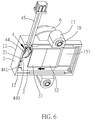
- FIG. 6 is a perspective diagram showing another scenario of the enclosure of FIG. 5 .
- FIG. 7 is a perspective diagram showing a magnetic element and a swing arm of the camera assembly of FIG. 3 .
- FIG. 8 is a perspective diagram showing the magnetic element and the swing arm of FIG. 7 .
- FIG. 9 shows another embodiment of the magnetic element and the swing arm of FIG. 3 .
- FIG. 10 is a perspective diagram showing the magnetic element and the swing arm of FIG. 9 .
- FIG. 11 is a sectional diagram showing the magnetic element and the swing arm of FIG. 9 .
- a camera assembly includes an enclosure 1 , a carrier plate 2 , a driver 4 , a cover piece 5 , and a lens barrel 6 .
- the enclosure 1 has a front side 11 and a back side 12 , and the enclosure 1 has a channel 13 inside.
- the channel 13 has a front end connecting the enclosure 1 's front side 11 , and, as such, provides a lens barrel socket 14 (as shown in FIG. 3 ) on the enclosure 1 's front side 11 .
- the lens barrel 6 is plugged into the lens barrel socket 14 .
- a back end of the channel 13 connects a chamber 15 of the enclosure 1 .
- the carrier plate 2 and the driver 4 are disposed in a space 151 of the chamber 15 .
- a number of filters 31 , 32 are disposed on the carrier plate 2 .
- the carrier plate 2 is guided from an upper wall and a lower wall of the space 151 and is moveable laterally and reciprocally in the space 151 .
- the driver 4 is disposed to a left side or right side of the space 151 .
- the carrier plate 2 provides a slot 21 adjacent to the driver 4 .
- the driver 4 has a swing arm 44 whose free end is embedded in the slot 21 of the carrier plate 2 . As shown in FIG. 5 , the driver 4 's swing arm 44 as such may engage the carrier plate 2 through the slot 21 to move reciprocally and laterally in the space 151 so that a filter 31 or 32 of the carrier plate 2 is aligned with the channel 13 .
- the cover piece 5 seals the chamber 15 and the cover piece 5 has an opening 51 corresponding to the channel 13 surrounded by a circumferential flange 52 on a back side of the cover piece 5 opposite to the filters 31 , 32 .
- the flange 52 forms and surrounds a chip space 53 where an image sensor chip 7 is installed.
- the filters 31 , 32 are therefore disposed between the channel 13 and the image sensor chip 7 .
- the image sensor chip 7 senses and captures images through the lens barrel 6 , the channel 13 , one of the filters filter 31 and 32 , and the opening 51 of the cover piece 5 .
- the chamber 15 inside the enclosure 1 to directly house the carrier plate 2 , filters 31 , 32 , driver 4 , image sensor chip 7 , there is no need for a chamber to house the filter package as taught by the prior art.
- the camera assembly therefore has a simplified structure, a reduced cost, and may be more effectively miniaturized.
- each protrusion 17 is embedded with a metallic bolt 18 whose circumference is axially configured with a number of gears 181 at intervals.
- Each gear 181 is configured with teeth 1811 .
- Each bolt 18 is locked to a protrusion 17 by the gears 181 for enhanced reliability.
- the bolts 18 have an end extended outside the protrusions 17 , where fasteners may be applied to fix the enclosure 1 to an external device.
- the free end of the swing arm 44 has a pin 440 for embedment in the slot 21
- the pin 440 has an extension 441 .
- the extension 441 may run through the slot 21 to be located to another side of the carrier plate 2 opposite to the swing arm 44 .
- the extension 441 therefore functions as a hook engaging the slot 21 .
- the swing arm 44 drives the carrier plate 2 into a lateral reciprocal movement by the pin 440 and the slot 21
- the extension 441 at the free end of the swing arm 44 prevents the swing arm 44 from breaking away from the slot 21 , thereby enhancing the reliability of the swing arm 44 's engagement to the carrier plate 2 .
- the driver 4 includes a first electromagnetic arm 41 , a second electromagnetic arm 42 , and a magnetic element 43 .
- the first electromagnetic arm 41 and second electromagnetic arm 42 are connected at one end and the other ends of the first electromagnetic arm 41 and second electromagnetic arm 42 respectively provide corresponding curved sections 411 , 421 so that the first electromagnetic arm 41 's curved sections 411 faces the second electromagnetic arm 42 's curved sections 421 .
- the first electromagnetic arm 41 and second electromagnetic arm 42 are respectively wound with windings 412 , 422 .
- the magnetic element 43 may be a magnet, and is rotatably held between the curved sections 411 , 421 .
- the swing arm 44 is fixedly joined to an axle of the magnetic element 43 .
- the windings 412 , 422 are connected to an external power source through a power cable 45 .
- the first electromagnetic arm 41 and the second electromagnetic arm 42 produce magnetic force to drive the magnetic element 43 , along with the swing arm 44 , to swing via the curved sections 411 , 421 .
- the carrier plate 2 is thereby moved.
- windings 412 , 422 of greater length may be applied and, as such, a steady magnetic drive is provided to the magnetic element 43 and swing arm 44 .
- the swing arm 44 has the extension 441 on a first end and an axle 442 at a second end. At least a protrusion 445 is radially extended from the axle 442 .
- the magnetic element 43 has an end-to-end axle channel 431 and at least a radial notch 432 .
- the magnetic element 43 is mounted on the second end of the swing arm 44 by plugging the axle 442 into the axle channel 431 and the protrusion 445 into the notch 432 .
- the axle channel 431 is connected to a square indentation 433 on a top side of the magnetic element 43 .
- a top end of the axle 442 has a square block 443 .
- the square block 443 is received by the square indentation 433 . As such, the swing arm 44 and the magnetic element 43 may be quickly coupled together.
Abstract
Description
Claims (6)
Priority Applications (1)
| Application Number | Priority Date | Filing Date | Title |
|---|---|---|---|
| US16/790,756 US11143933B2 (en) | 2019-01-08 | 2020-02-14 | Camera assembly |
Applications Claiming Priority (2)
| Application Number | Priority Date | Filing Date | Title |
|---|---|---|---|
| US16/243,053 US20200218131A1 (en) | 2019-01-08 | 2019-01-08 | Lens screening device |
| US16/790,756 US11143933B2 (en) | 2019-01-08 | 2020-02-14 | Camera assembly |
Related Parent Applications (1)
| Application Number | Title | Priority Date | Filing Date |
|---|---|---|---|
| US16/243,053 Continuation-In-Part US20200218131A1 (en) | 2019-01-08 | 2019-01-08 | Lens screening device |
Publications (2)
| Publication Number | Publication Date |
|---|---|
| US20200218129A1 US20200218129A1 (en) | 2020-07-09 |
| US11143933B2 true US11143933B2 (en) | 2021-10-12 |
Family
ID=71403482
Family Applications (1)
| Application Number | Title | Priority Date | Filing Date |
|---|---|---|---|
| US16/790,756 Active 2039-03-21 US11143933B2 (en) | 2019-01-08 | 2020-02-14 | Camera assembly |
Country Status (1)
| Country | Link |
|---|---|
| US (1) | US11143933B2 (en) |
Citations (8)
| Publication number | Priority date | Publication date | Assignee | Title |
|---|---|---|---|---|
| US20030161049A1 (en) * | 2002-02-22 | 2003-08-28 | Tadanori Okada | Optical apparatus |
| US20050083431A1 (en) * | 2003-09-18 | 2005-04-21 | Sony Corporation | Image taking apparatus |
| US20070211162A1 (en) * | 2006-03-09 | 2007-09-13 | Shoji Kaihara | Image capturing apparatus, control method therefor, and program |
| US20080106805A1 (en) * | 2006-11-06 | 2008-05-08 | Daigo Aiba | Lens device |
| US20120008930A1 (en) * | 2010-07-09 | 2012-01-12 | Barley Christopher B | Action camera with capability of capturing images in daylight and infrared |
| US20150042818A1 (en) * | 2013-08-06 | 2015-02-12 | Panasonic Corporation | Camera apparatus and filter unit |
| US20190163242A1 (en) * | 2017-11-30 | 2019-05-30 | Guangdong Oppo Mobile Telecommunications Corp., Ltd. | Camera assembly, electronic apparatus, and mobile terminal |
| US20200007730A1 (en) * | 2017-03-23 | 2020-01-02 | Sony Corporation | Interchangeable lens and method for controlling the same, shooting apparatus, and camera system |
-
2020
- 2020-02-14 US US16/790,756 patent/US11143933B2/en active Active
Patent Citations (8)
| Publication number | Priority date | Publication date | Assignee | Title |
|---|---|---|---|---|
| US20030161049A1 (en) * | 2002-02-22 | 2003-08-28 | Tadanori Okada | Optical apparatus |
| US20050083431A1 (en) * | 2003-09-18 | 2005-04-21 | Sony Corporation | Image taking apparatus |
| US20070211162A1 (en) * | 2006-03-09 | 2007-09-13 | Shoji Kaihara | Image capturing apparatus, control method therefor, and program |
| US20080106805A1 (en) * | 2006-11-06 | 2008-05-08 | Daigo Aiba | Lens device |
| US20120008930A1 (en) * | 2010-07-09 | 2012-01-12 | Barley Christopher B | Action camera with capability of capturing images in daylight and infrared |
| US20150042818A1 (en) * | 2013-08-06 | 2015-02-12 | Panasonic Corporation | Camera apparatus and filter unit |
| US20200007730A1 (en) * | 2017-03-23 | 2020-01-02 | Sony Corporation | Interchangeable lens and method for controlling the same, shooting apparatus, and camera system |
| US20190163242A1 (en) * | 2017-11-30 | 2019-05-30 | Guangdong Oppo Mobile Telecommunications Corp., Ltd. | Camera assembly, electronic apparatus, and mobile terminal |
Also Published As
| Publication number | Publication date |
|---|---|
| US20200218129A1 (en) | 2020-07-09 |
Similar Documents
| Publication | Publication Date | Title |
|---|---|---|
| US20190253533A1 (en) | Mobile terminal | |
| US20190253540A1 (en) | Mobile terminal | |
| US11258934B2 (en) | Image capturing assembly and electronic device | |
| EP3633447B1 (en) | Lens driving device, camera module and optical device | |
| US7973284B2 (en) | Image sensing module | |
| CN1637582A (en) | Lens holder apparatus of camera lens module | |
| US20110019072A1 (en) | Image capturing device and electronic device using same | |
| EP2785044A2 (en) | Camera module | |
| CN104584528A (en) | Camera module | |
| US11143933B2 (en) | Camera assembly | |
| KR20130008769A (en) | Camera module | |
| US10574875B2 (en) | Camera module | |
| KR102160773B1 (en) | Motor for actuating lens and camera module | |
| CN104918433A (en) | Protection shell and electronic device to which protection shell is applied | |
| CN109981936B (en) | Functional module, electronic device and control method of electronic device | |
| US9432558B2 (en) | Image capturing module having a built-in dustproof structure | |
| KR20230014816A (en) | Motor for actuating lens | |
| CN108923689B (en) | Electronic equipment and transmission assembly | |
| KR102490563B1 (en) | Motor for actuating lens | |
| KR100956211B1 (en) | Camera module | |
| KR100832635B1 (en) | multi camera module | |
| KR102187735B1 (en) | Camera module | |
| US8885098B2 (en) | Cameral module with sealing structure for portable electronic devices | |
| CN109951589B (en) | Functional module, electronic device and control method of electronic device | |
| CN109981935B (en) | Functional module, electronic device and control method of electronic device |
Legal Events
| Date | Code | Title | Description |
|---|---|---|---|
| FEPP | Fee payment procedure |
Free format text: ENTITY STATUS SET TO UNDISCOUNTED (ORIGINAL EVENT CODE: BIG.); ENTITY STATUS OF PATENT OWNER: SMALL ENTITY |
|
| AS | Assignment |
Owner name: FUNDER ELECTRONIC GLOBAL CO., LTD., TAIWAN Free format text: ASSIGNMENT OF ASSIGNORS INTEREST;ASSIGNOR:WENG, WAI-HOW;REEL/FRAME:051828/0241 Effective date: 20200205 |
|
| FEPP | Fee payment procedure |
Free format text: ENTITY STATUS SET TO SMALL (ORIGINAL EVENT CODE: SMAL); ENTITY STATUS OF PATENT OWNER: SMALL ENTITY |
|
| STPP | Information on status: patent application and granting procedure in general |
Free format text: DOCKETED NEW CASE - READY FOR EXAMINATION |
|
| STPP | Information on status: patent application and granting procedure in general |
Free format text: EX PARTE QUAYLE ACTION MAILED |
|
| STPP | Information on status: patent application and granting procedure in general |
Free format text: RESPONSE TO EX PARTE QUAYLE ACTION ENTERED AND FORWARDED TO EXAMINER |
|
| STPP | Information on status: patent application and granting procedure in general |
Free format text: NOTICE OF ALLOWANCE MAILED -- APPLICATION RECEIVED IN OFFICE OF PUBLICATIONS |
|
| STPP | Information on status: patent application and granting procedure in general |
Free format text: PUBLICATIONS -- ISSUE FEE PAYMENT VERIFIED |
|
| STCF | Information on status: patent grant |
Free format text: PATENTED CASE |